Embed Size (px)
Citation preview
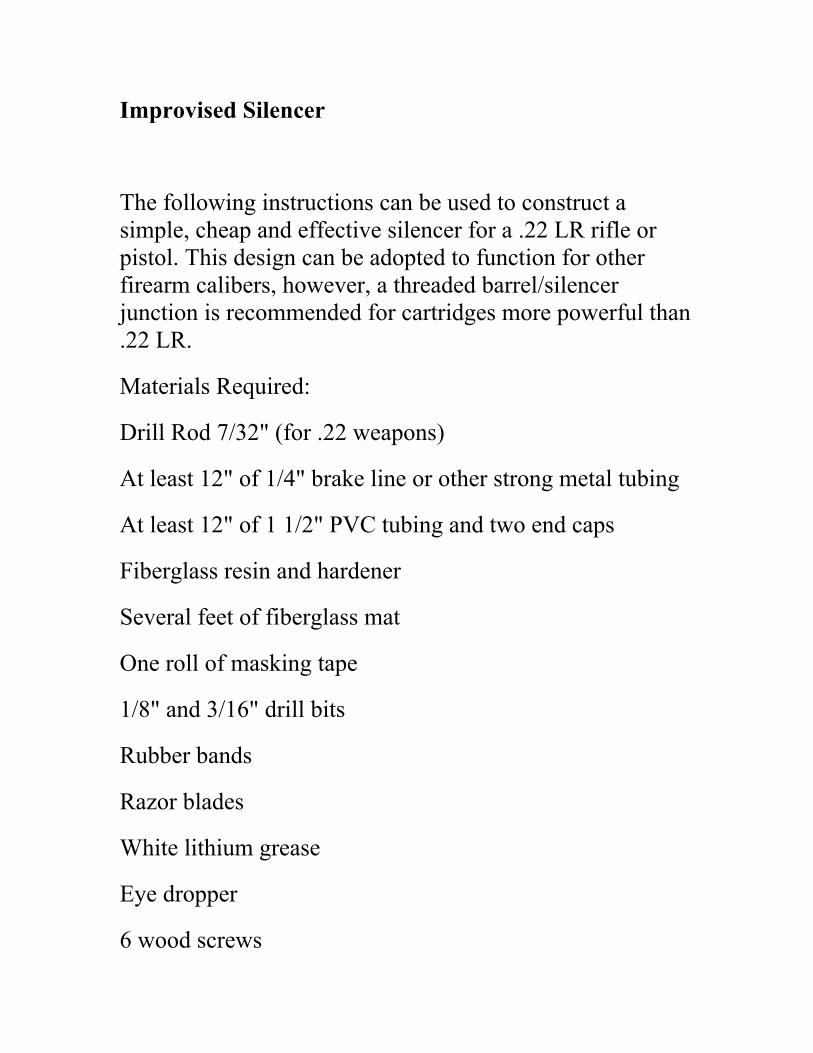
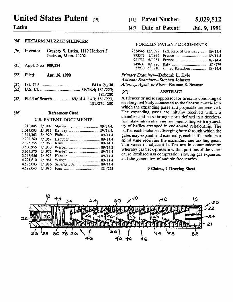
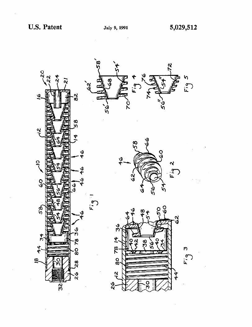
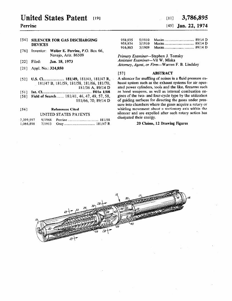
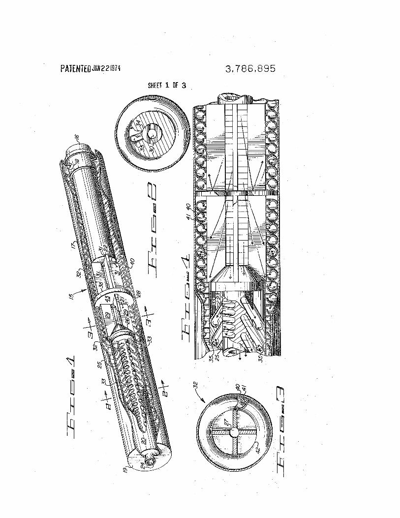
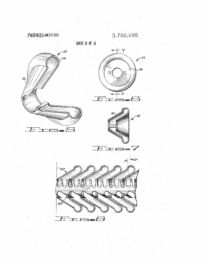
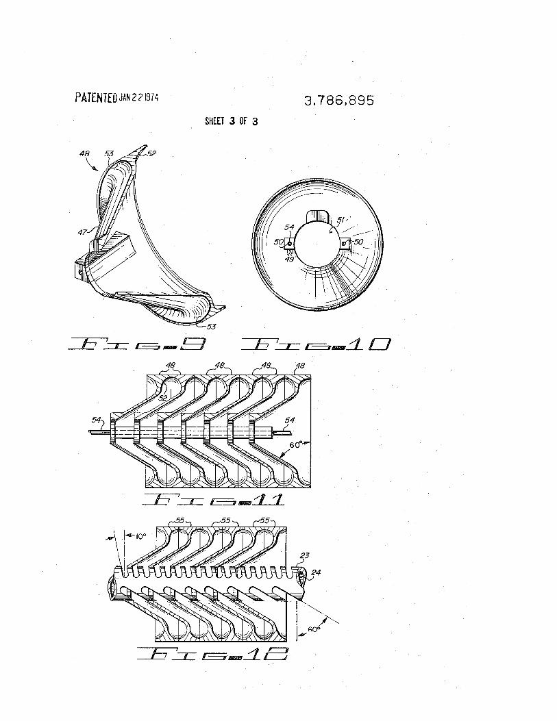
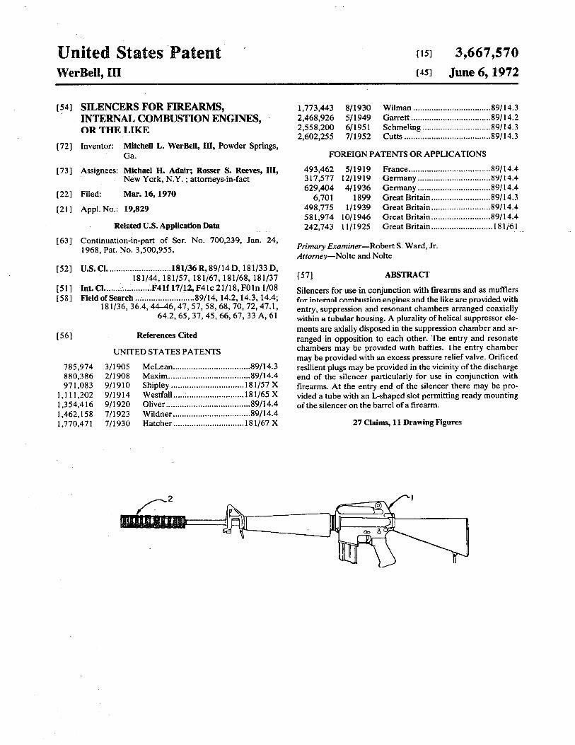
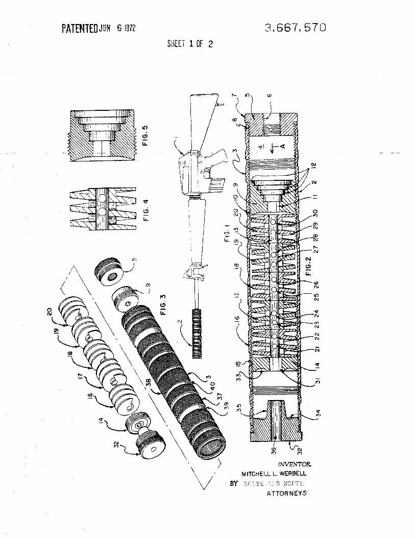
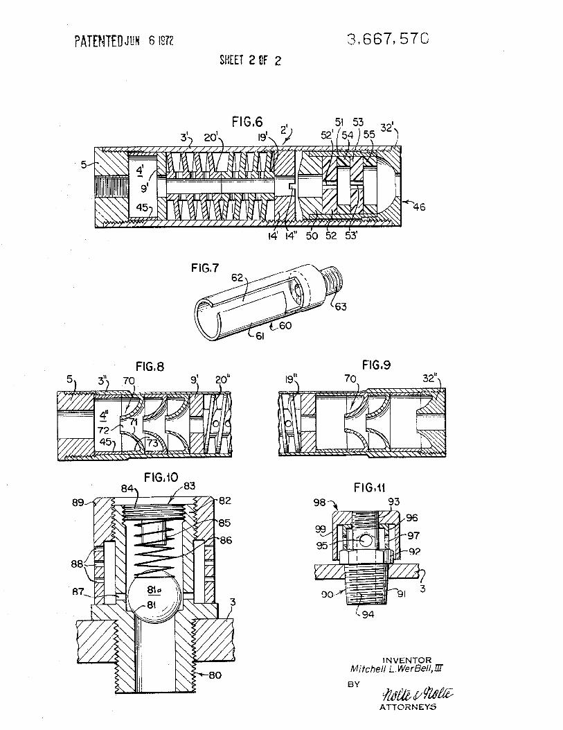
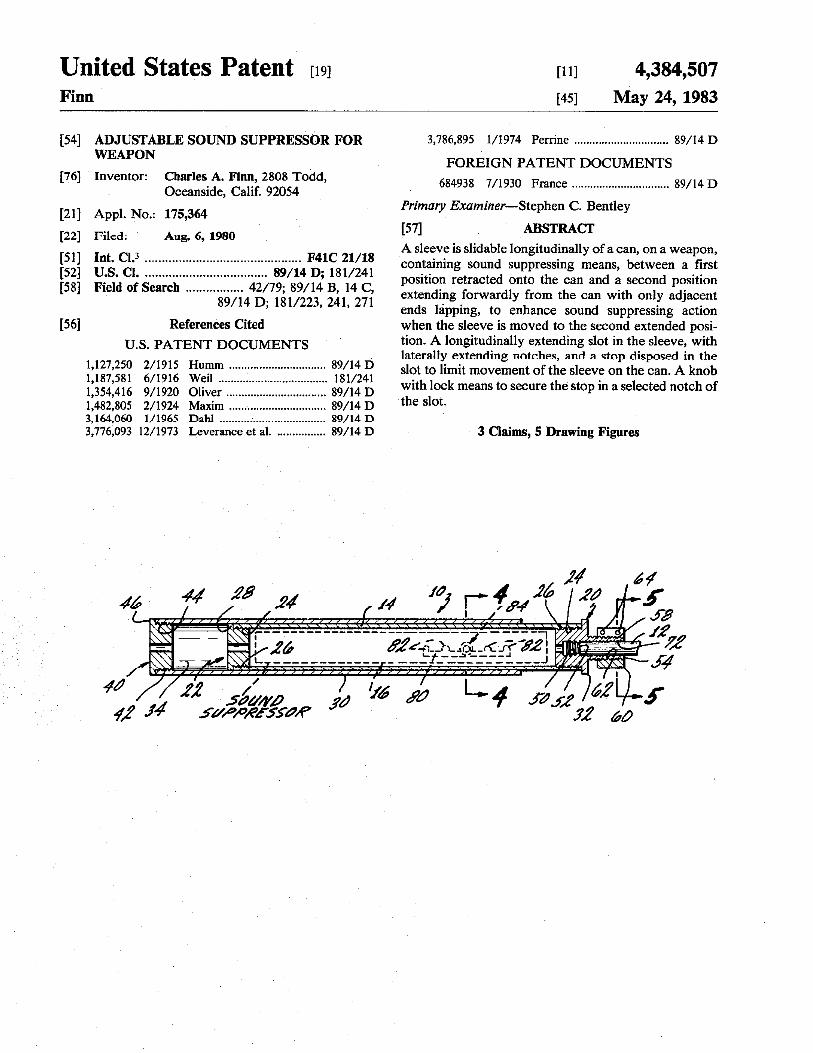
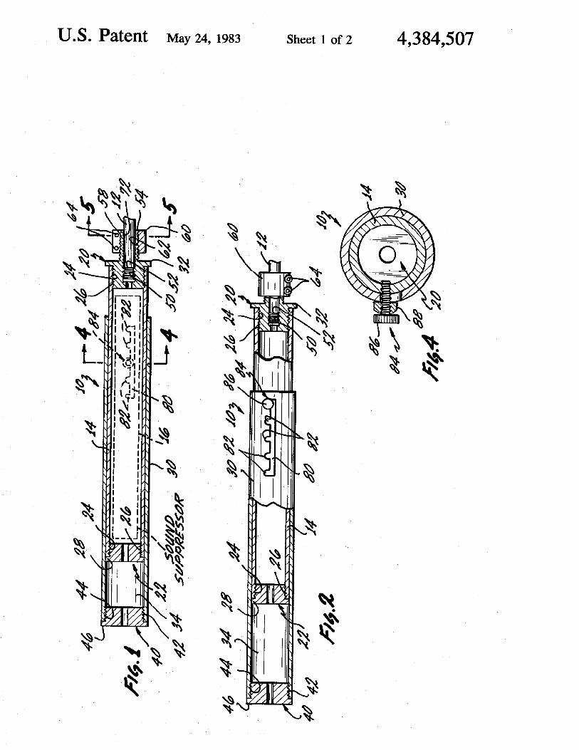
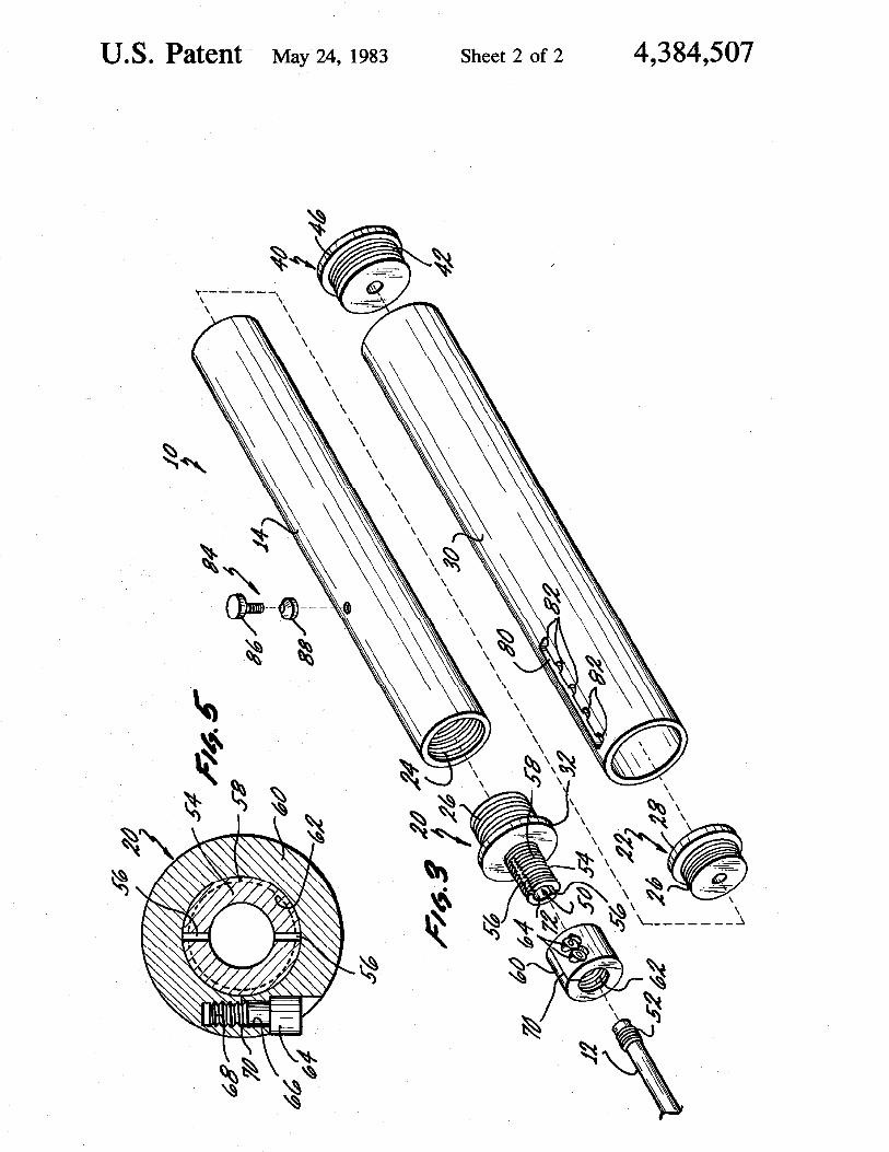
Improvised Silencer
The following instructions can be used to construct a simple, cheap and effective silencer for a .22 LR rifle or pistol. This design can be adopted to function for other firearm calibers, however, a threaded barrel/silencer junction is recommended for cartridges more powerful than .22 LR.
Materials Required:
Drill Rod 7/32" (for .22 weapons)
At least 12" of 1/4" brake line or other strong metal tubing
At least 12" of 1 1/2" PVC tubing and two end caps
Fiberglass resin and hardener
Several feet of fiberglass mat
One roll of masking tape
1/8" and 3/16" drill bits
Rubber bands
Razor blades
White lithium grease
Eye dropper
6 wood screws
Steel wool
80x sand paper
Construction:
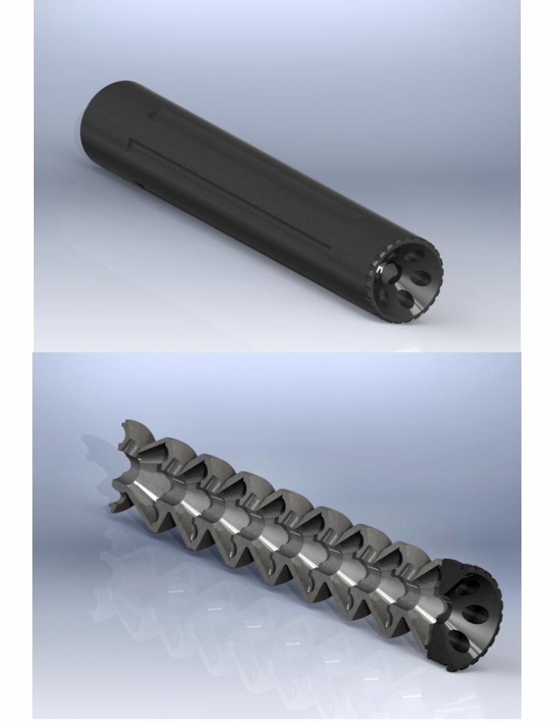
Cut a 10" section from the brake line and drill a series of 1/8" holes along its length beginning 1 1/2" from the end.
Next, enlarge the holes using a 3/16" drill bit.
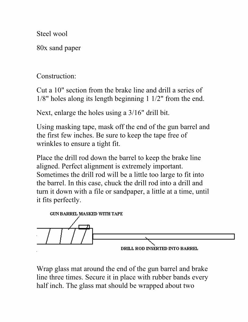
Using masking tape, mask off the end of the gun barrel and the first few inches. Be sure to keep the tape free of wrinkles to ensure a tight fit.
Place the drill rod down the barrel to keep the brake line aligned. Perfect alignment is extremely important. Sometimes the drill rod will be a little too large to fit into the barrel. In this case, chuck the drill rod into a drill and turn it down with a file or sandpaper, a little at a time, until it fits perfectly.
Wrap glass mat around the end of the gun barrel and brake line three times. Secure it in place with rubber bands every half inch. The glass mat should be wrapped about two
inches behind the sight and up to the first holes on the brake line.
Now mix the resin. A few spoonfuls will do. Mix it two or three times hotter than the package directions.
Brace the weapon in an upright position and dab the resin onto the glass mat with a brush. Keep applying resin until the mat is no longer white but becomes transparent from absorption of the resin.
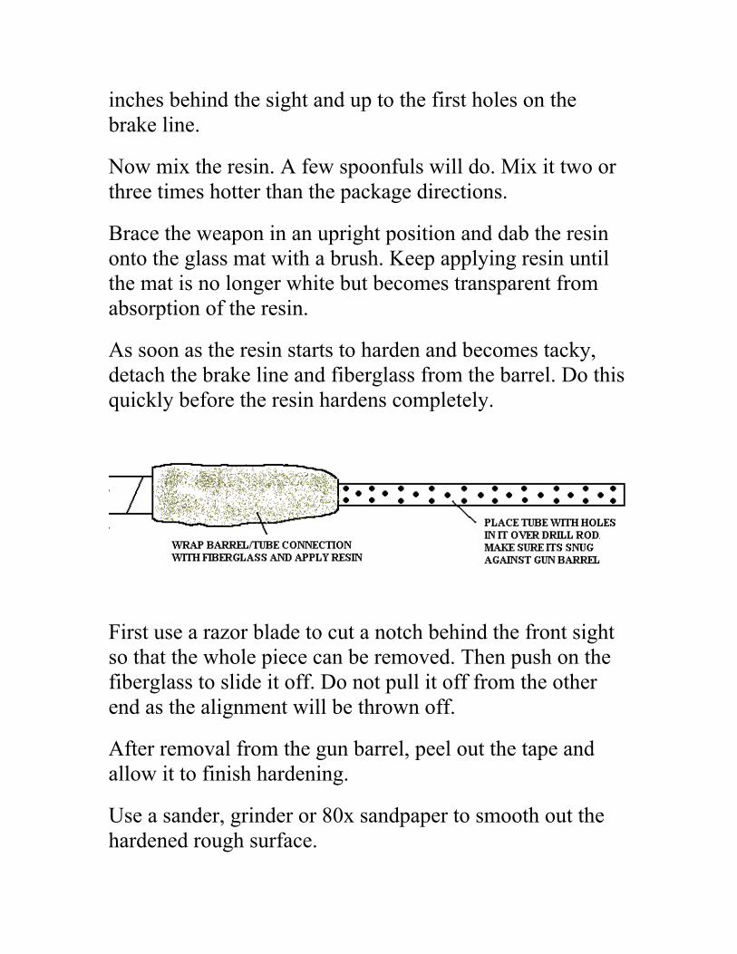
As soon as the resin starts to harden and becomes tacky, detach the brake line and fiberglass from the barrel. Do this quickly before the resin hardens completely.
First use a razor blade to cut a notch behind the front sight so that the whole piece can be removed. Then push on the fiberglass to slide it off. Do not pull it off from the other end as the alignment will be thrown off.
After removal from the gun barrel, peel out the tape and allow it to finish hardening.
Use a sander, grinder or 80x sandpaper to smooth out the hardened rough surface.
Next, grind the sides down about halfway, but do not grind past the point where the front sight makes contact. Cut it down until the barrel fits snuggly and easily.
Stand the glassed brake line upright in a vise.
Mix a small amount of resin and use an eyedropper to fill in any interior holes or air bubbles until the solid fiberglass is level with the steel tube end. This will give the junction between the brake line and fiberglass coupling added strength. Acetone can be used to clean the eyedropper.
Cut the PVC tubing to the desired length. A longer silencer will be necessary for more powerful cartridges.
Drill a large hole in the center of one end cap, making it large enough to fit on the fiberglass end to the point where the front sight makes contact.
Drill a series of 3/16" holes in the bottom of the end cap.
Wrap masking tape around the end cap to cover the holes.
Stand the cap with the inside tube inserted into a vise. Get the cap level and straight with the brake line.
Cut two dozen or so 1/2" squares of fiberglass mat and fill the end cap with it up past the level of the row of holes.
Mix resin and pour it over the cut matting to a point about 1/4" above the holes and allow it to dry before removing the cap from the vise. Don't worry about any resin that leaks out around the base hole. Resin fills the small holes,
making the tube strong enough to withstand the muzzle blast.
When the inside is hardened, turn the assembly over and fiberglass around the backside of the end cap for added strength. Avoid getting resin in the opening where the barrel fits.
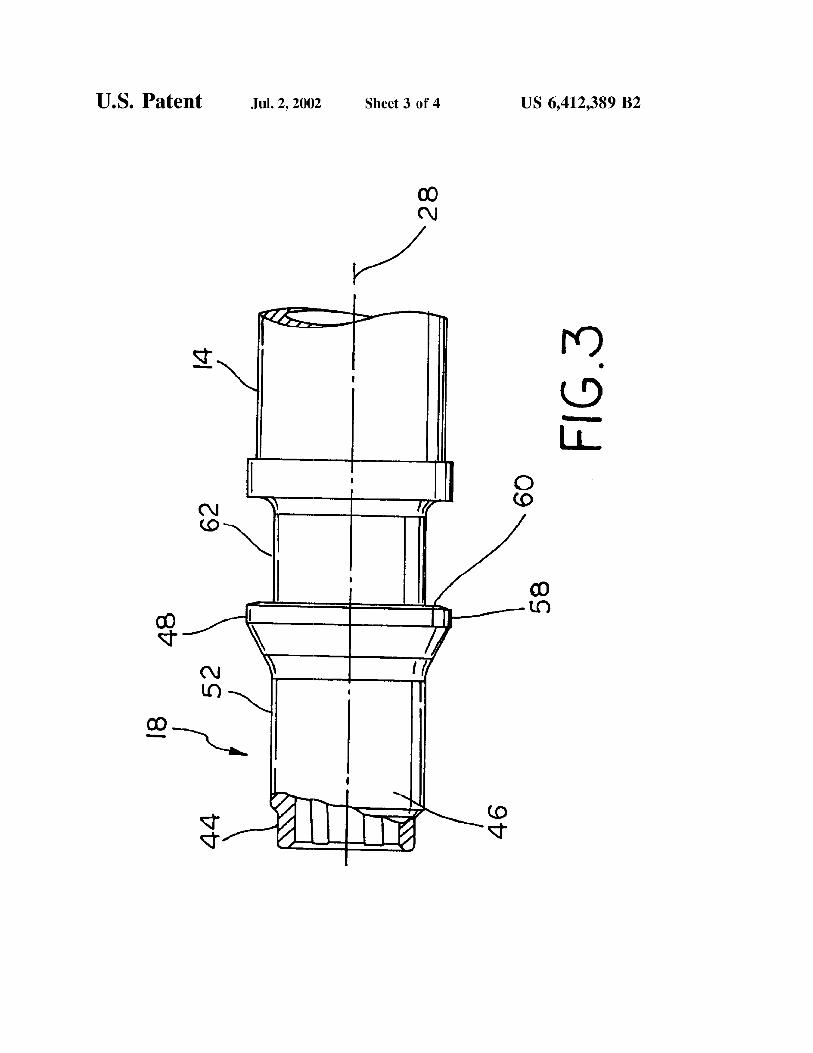
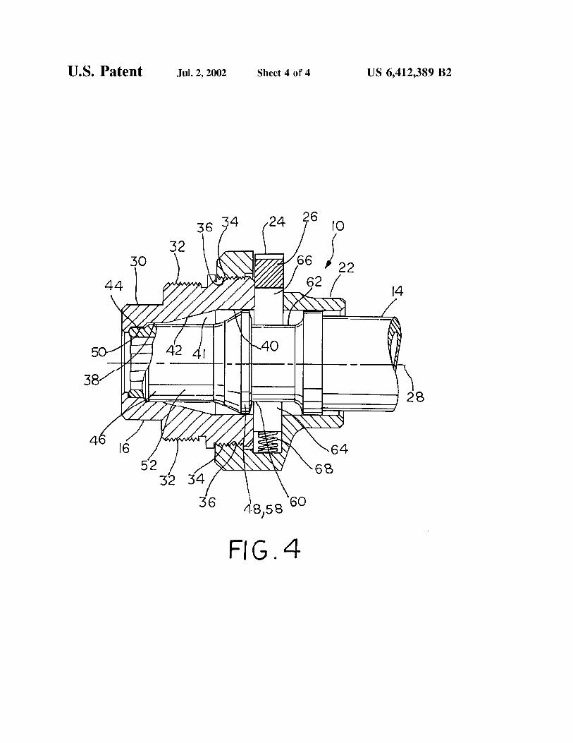
Place the finished cap and inner tube on one end of the PVC tubing that has already been cut to size. Center the brake line as you look in the open end of the PVC.
Now drill a 1/8" hole in three places around the tube about 1/4" from the lip of the cap.
Take the brake line out and enlarge the holes in the cap to 3/16"
Replace the brake line and tighten it down with three small wood screws.
Trim the brake line down until it extends about 1/2" beyond the PVC tube.
Sharpen one end of the drill rod to a point and use it as a center-punch. Stand the assembly up with the solid end cap down. Drop the drill rod down the brake line to get a true center mark.
Using a drill bit slightly larger than the outside diameter of the brake line, remove the end cap and drill the hole.
Cut a circle of 1/4" thick rubber which fits snuggly into the end cap. This rubber swipe will help prevent any hot gasses
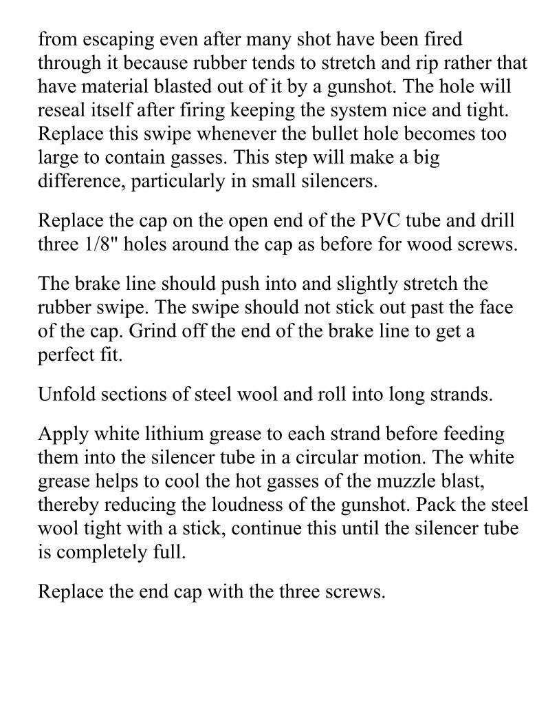
from escaping even after many shot have been fired through it because rubber tends to stretch and rip rather that have material blasted out of it by a gunshot. The hole will reseal itself after firing keeping the system nice and tight. Replace this swipe whenever the bullet hole becomes too large to contain gasses. This step will make a big difference, particularly in small silencers.
Replace the cap on the open end of the PVC tube and drill three 1/8" holes around the cap as before for wood screws.
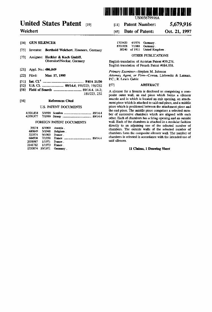
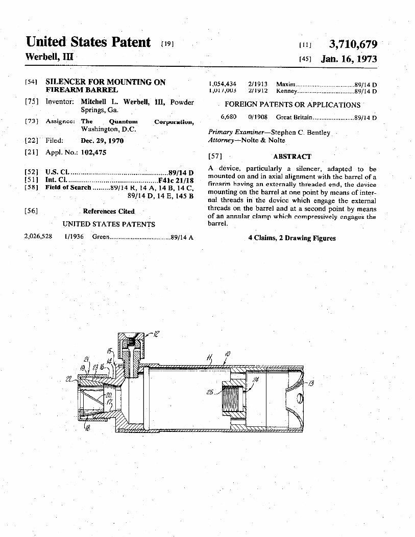
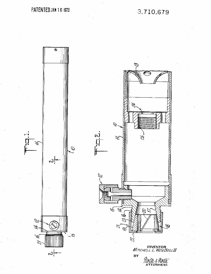
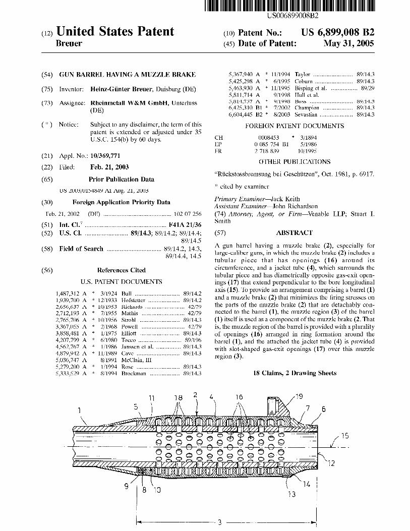
The brake line should push into and slightly stretch the rubber swipe. The swipe should not stick out past the face of the cap. Grind off the end of the brake line to get a perfect fit.
Unfold sections of steel wool and roll into long strands.
Apply white lithium grease to each strand before feeding them into the silencer tube in a circular motion. The white grease helps to cool the hot gasses of the muzzle blast, thereby reducing the loudness of the gunshot. Pack the steel wool tight with a stick, continue this until the silencer tube is completely full.
Replace the end cap with the three screws.
Paint the finished silencer flat black and attach it to your weapon. Proper alignment can be ensured by using a hose clamp around the barrel extension behind the front sight. Test as described in the Silenced .22 LR Weapons.
This silencer can be counted on to function for over 300 rounds before it will be necessary to open it up and repack it with new steel wool and lithium grease.
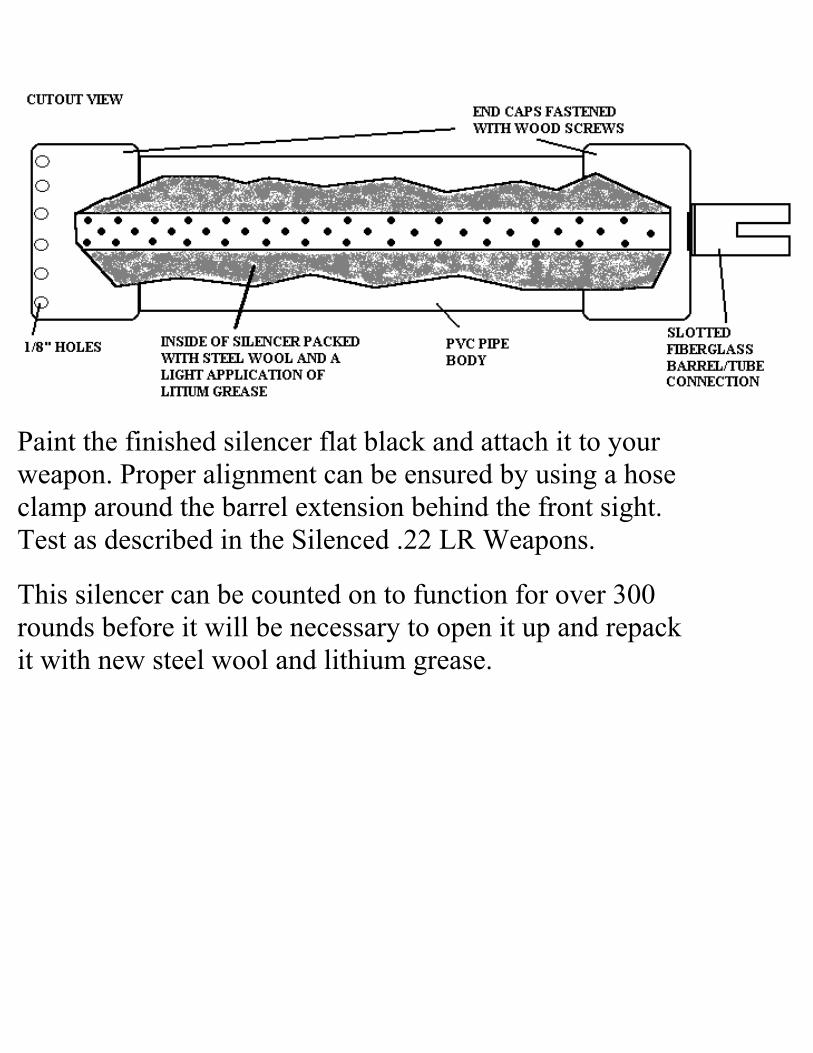
• "Tornado Tube" Plastic Water bottle(11.2 fl. oz/330ml) • Medium coarse steel wool pads (2) • Section of 1/2" PVC pipe
This silencer takes its name from the adapter fashioned from an educational toy sold in teacher supply stores. The Tornado Tube is a short plastic cylinder threaded in both ends and used to connect two large plastic soft drink bottles mouth to mouth. By filling one of the bottles with water and inverting it over the other bottle according to instructions, a tornado-like whirlpool vortex can be created as the water drains from the upper bottle, through the Tornado Tube, and into the lower bottle.
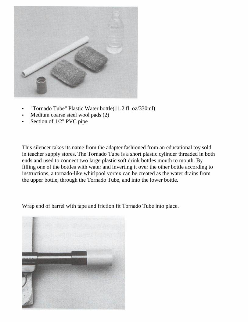
Wrap end of barrel with tape and friction fit Tornado Tube into place.
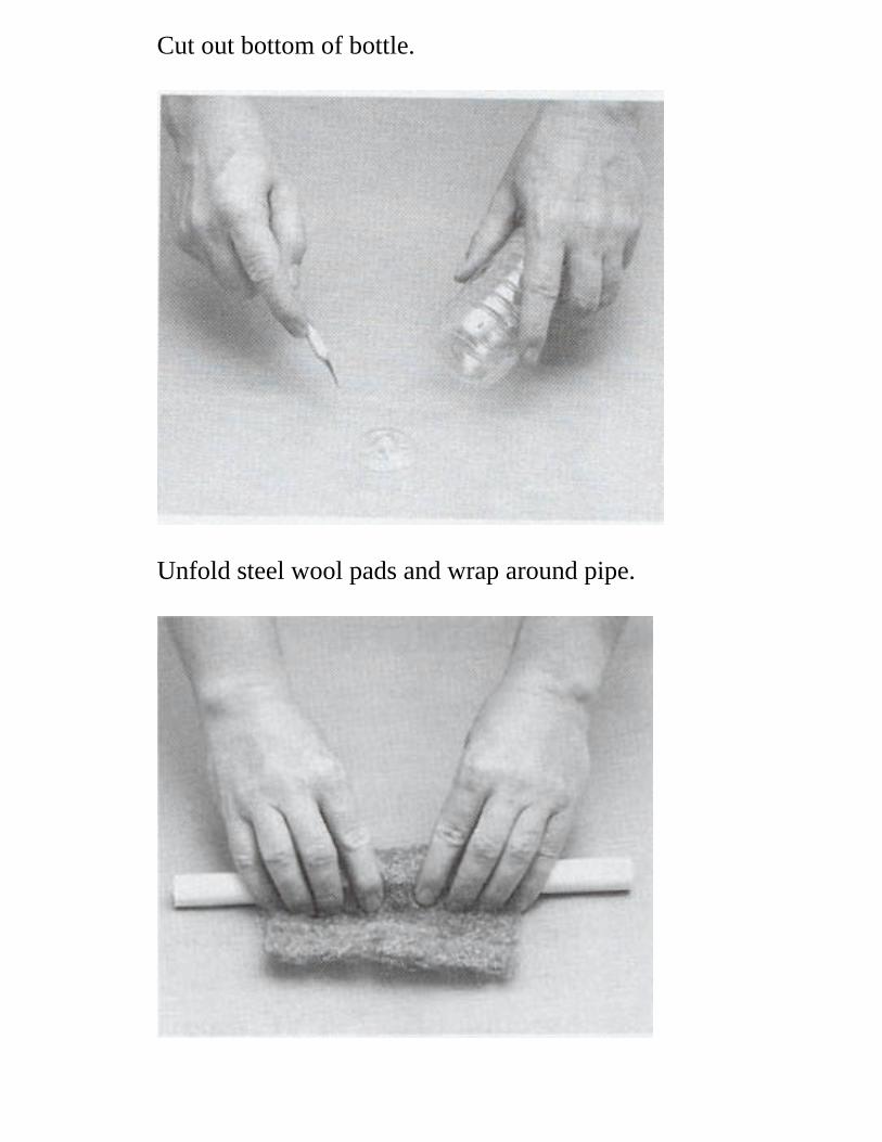
Cut out bottom of bottle.
Unfold steel wool pads and wrap around pipe.
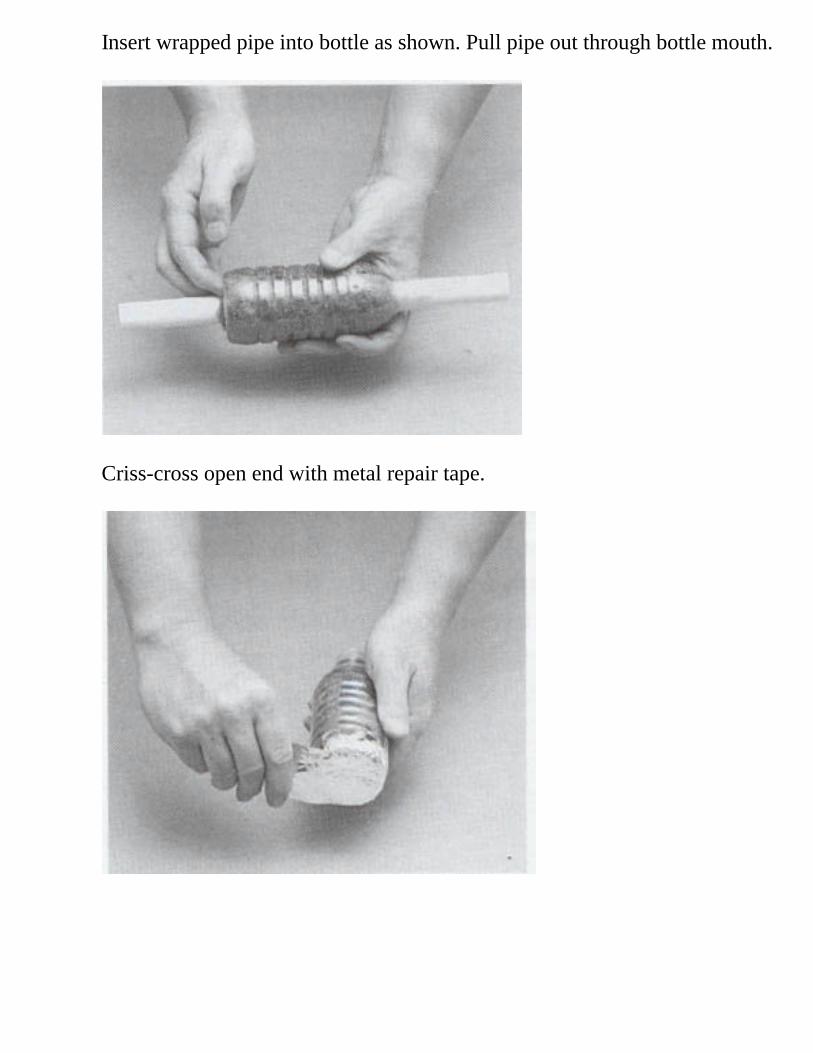
Insert wrapped pipe into bottle as shown. Pull pipe out through bottle mouth.
Criss-cross open end with metal repair tape.
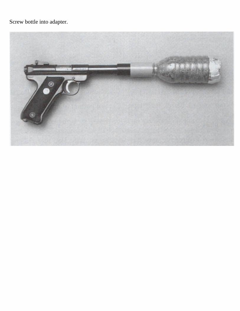
Screw bottle into adapter.

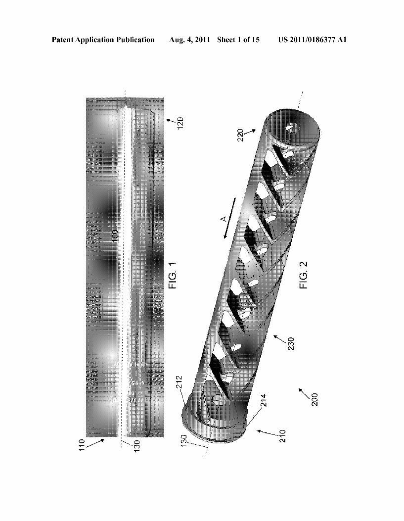
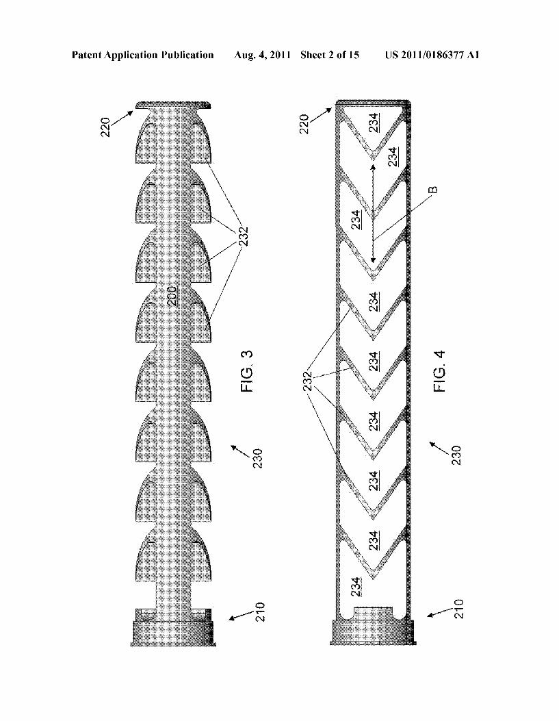


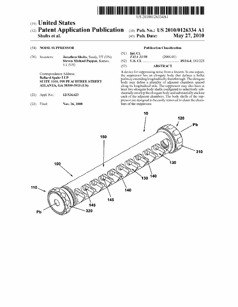
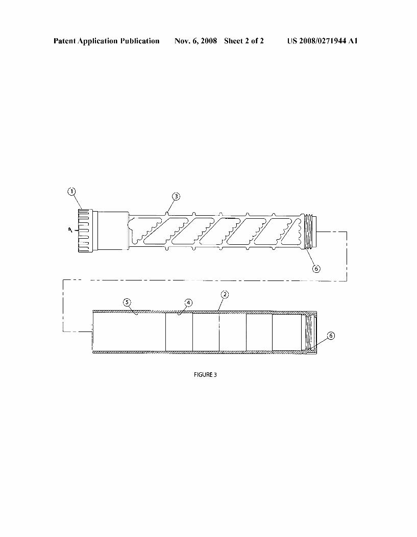
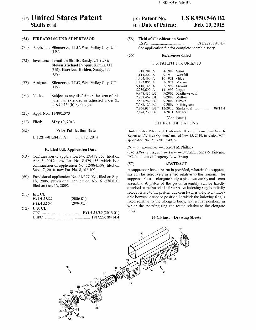
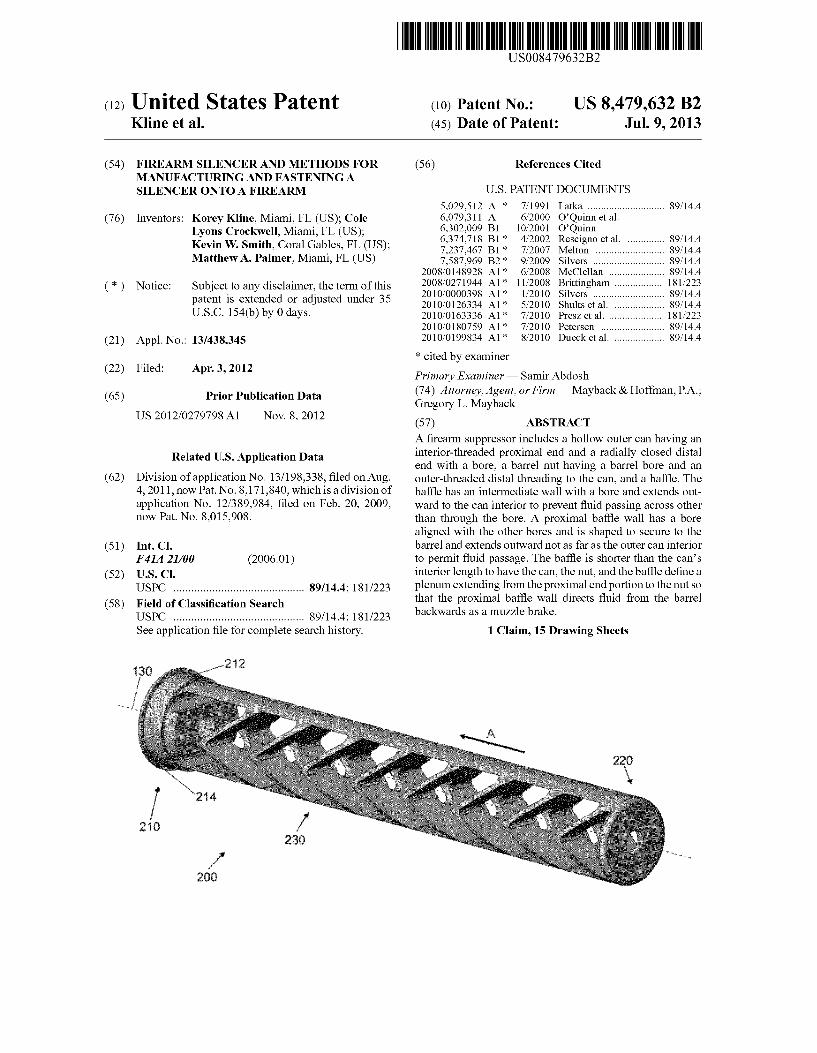
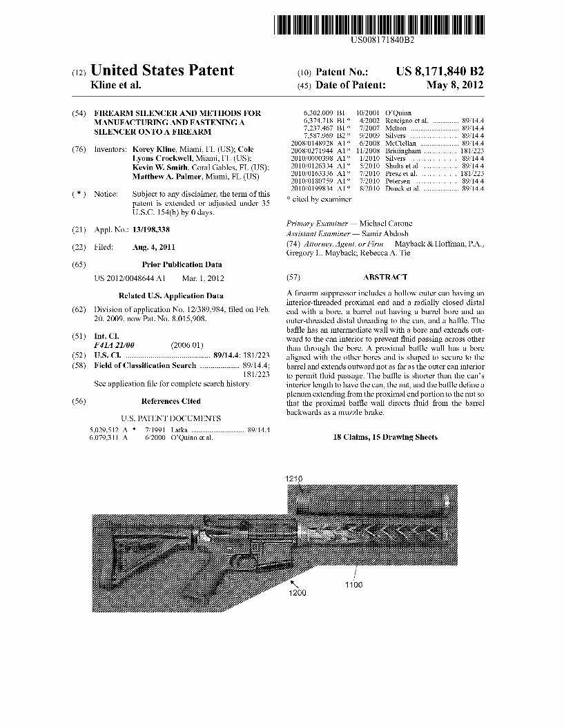
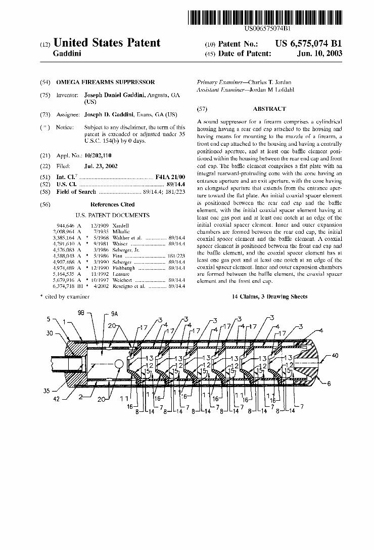
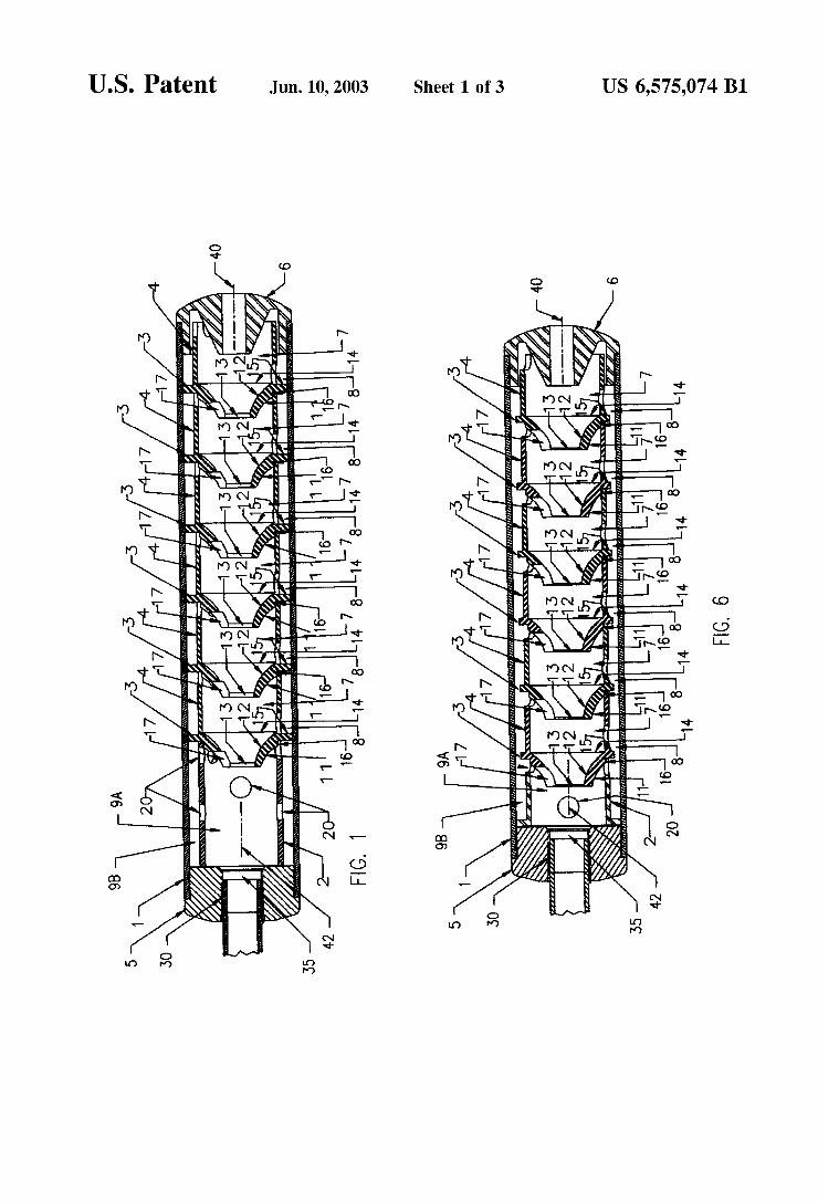
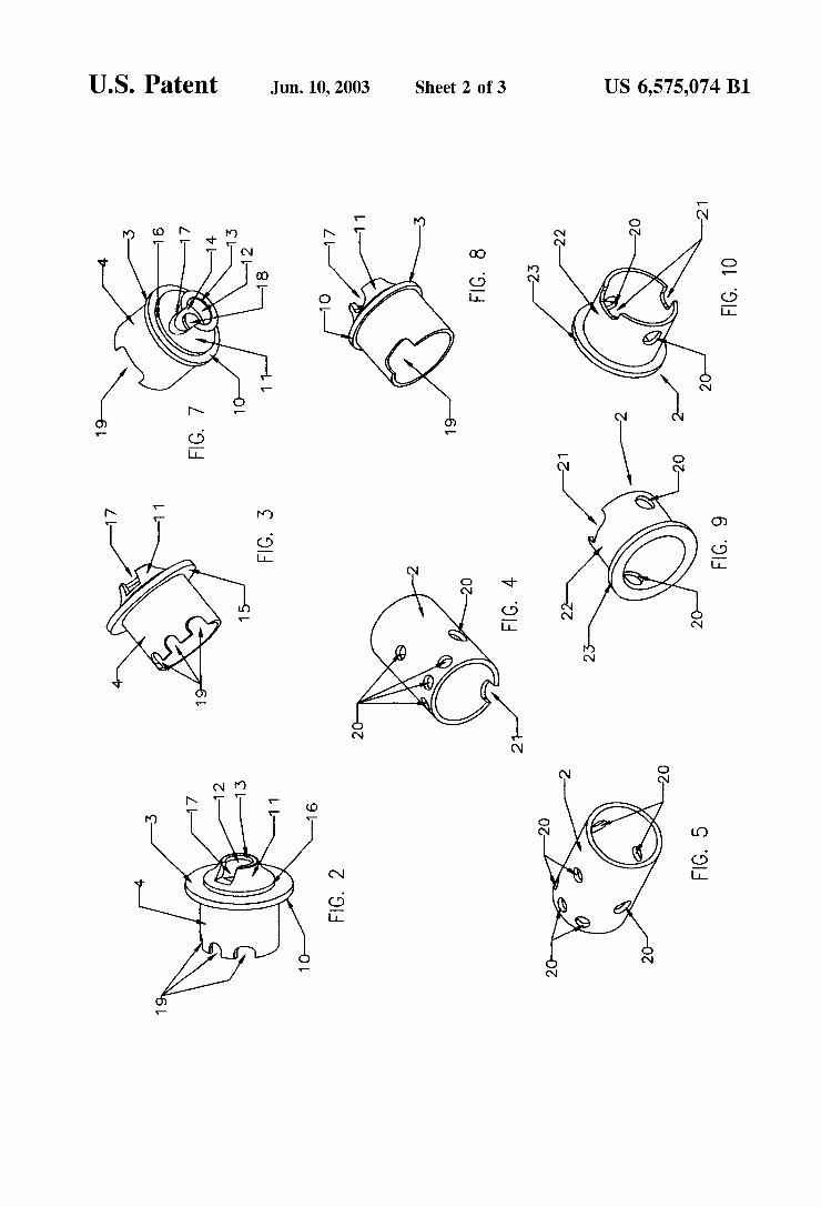
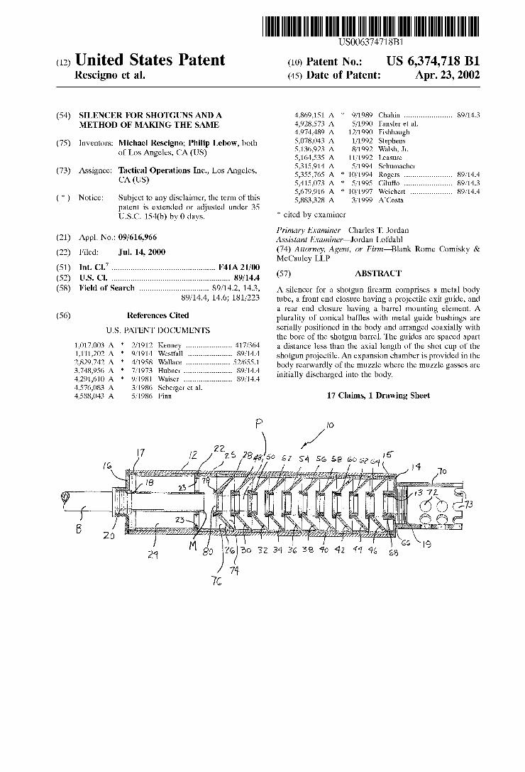
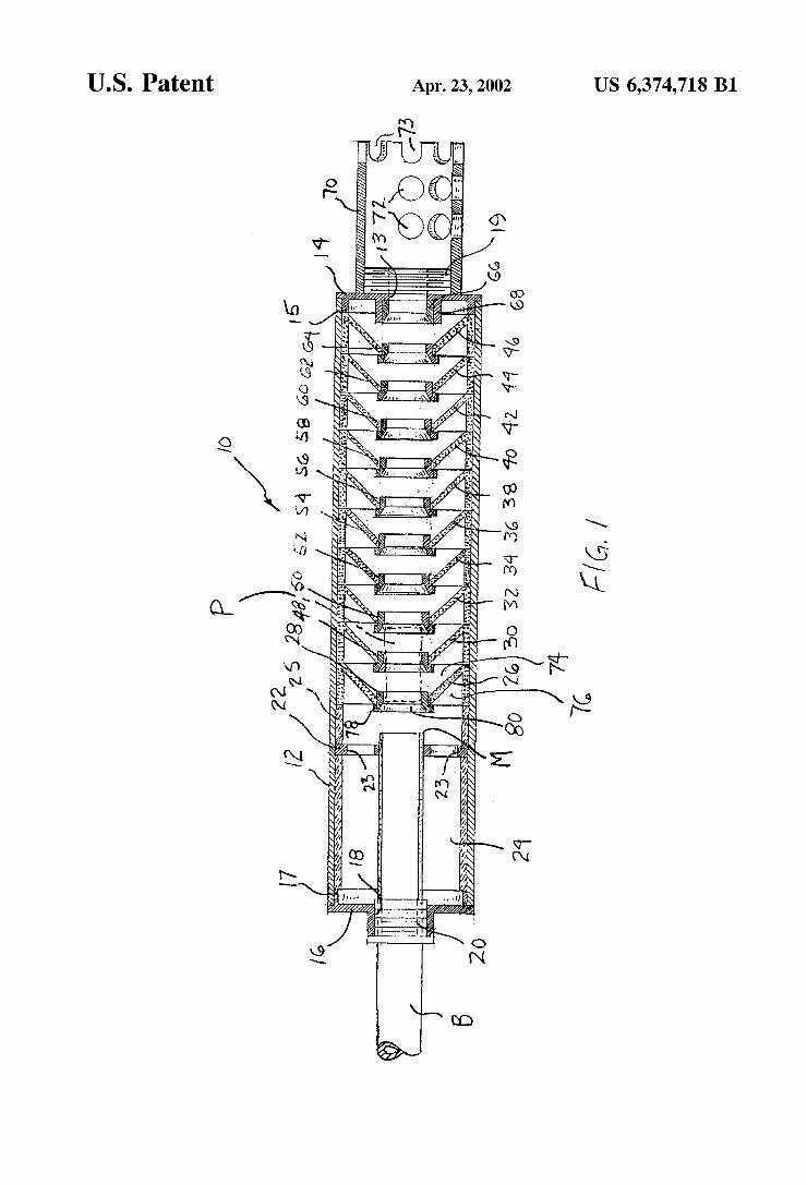
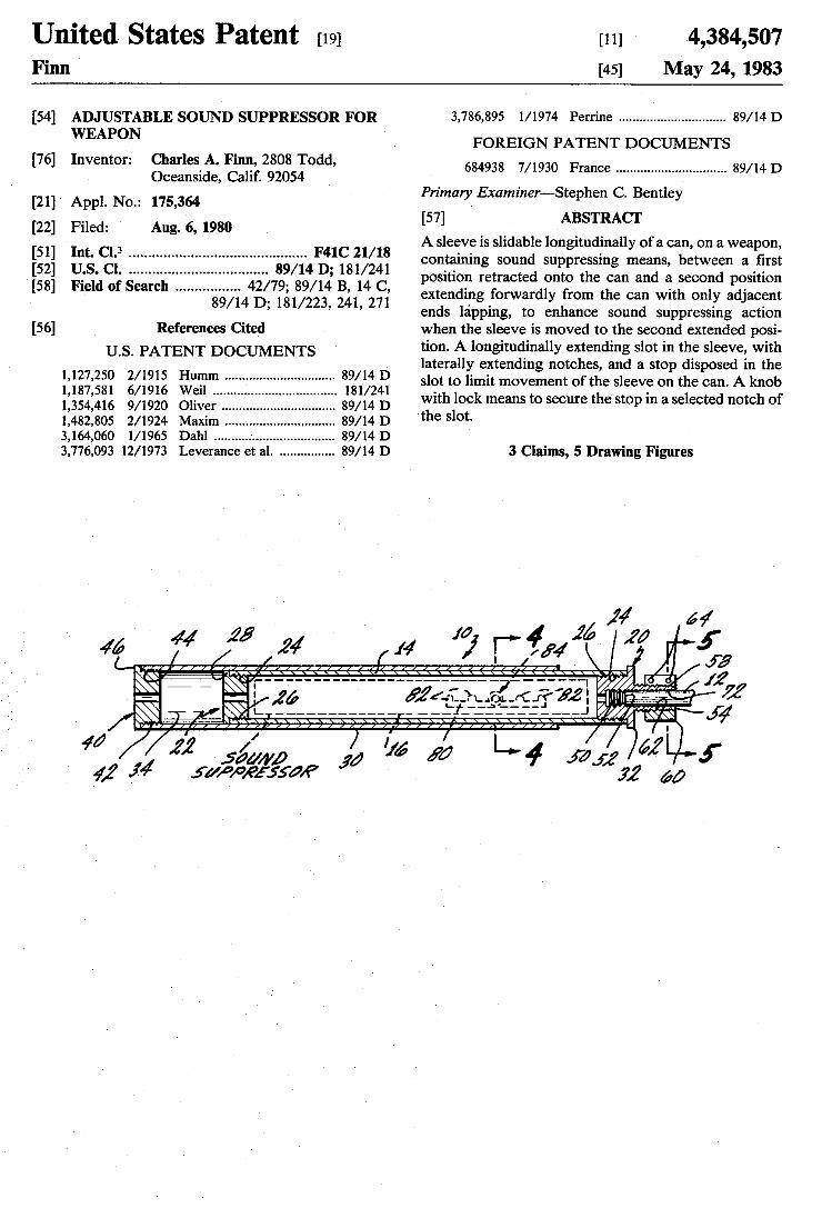
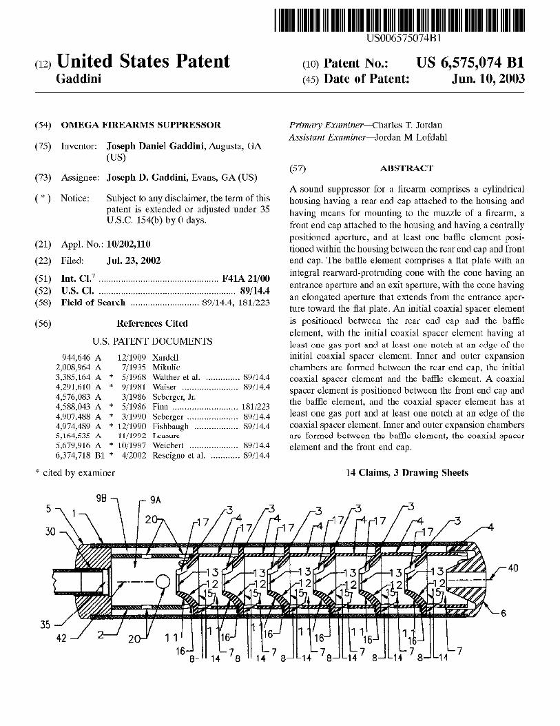
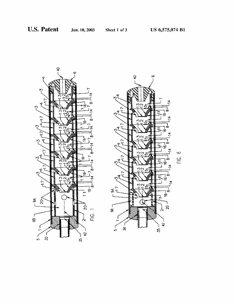
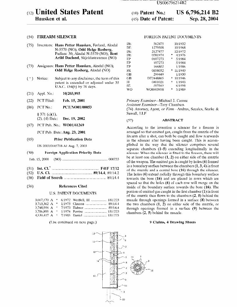
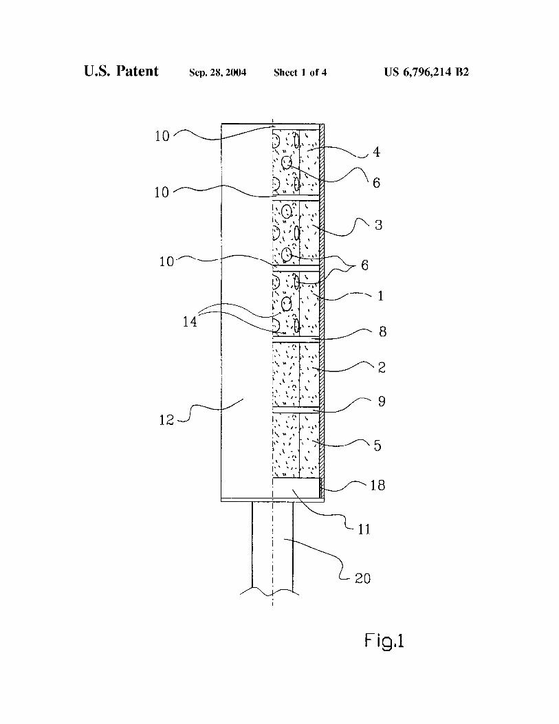
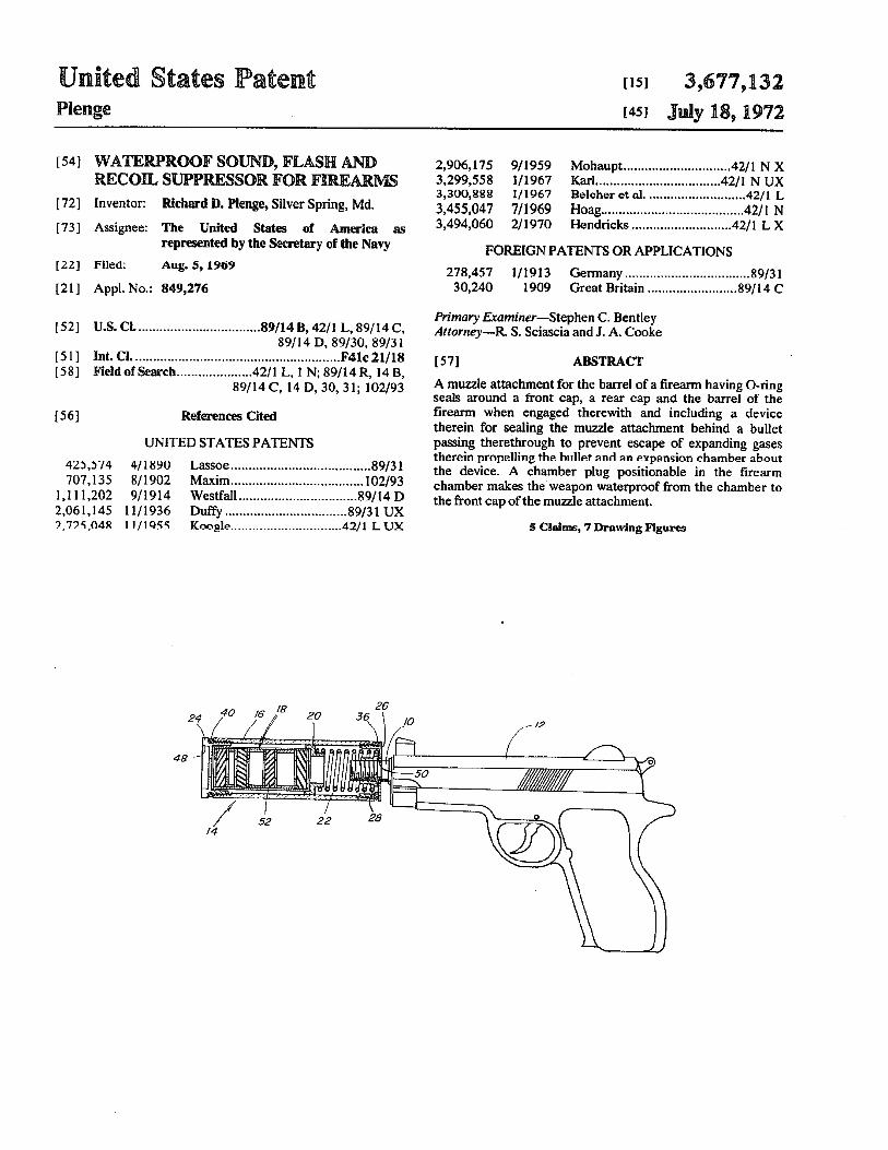
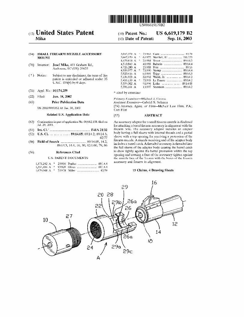
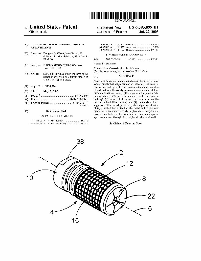
(12) United States Patent Shults et a].
USOO8950546B2
US 8,950,546 B2 Feb. 10, 2015
(10) Patent N0.: (45) Date of Patent:
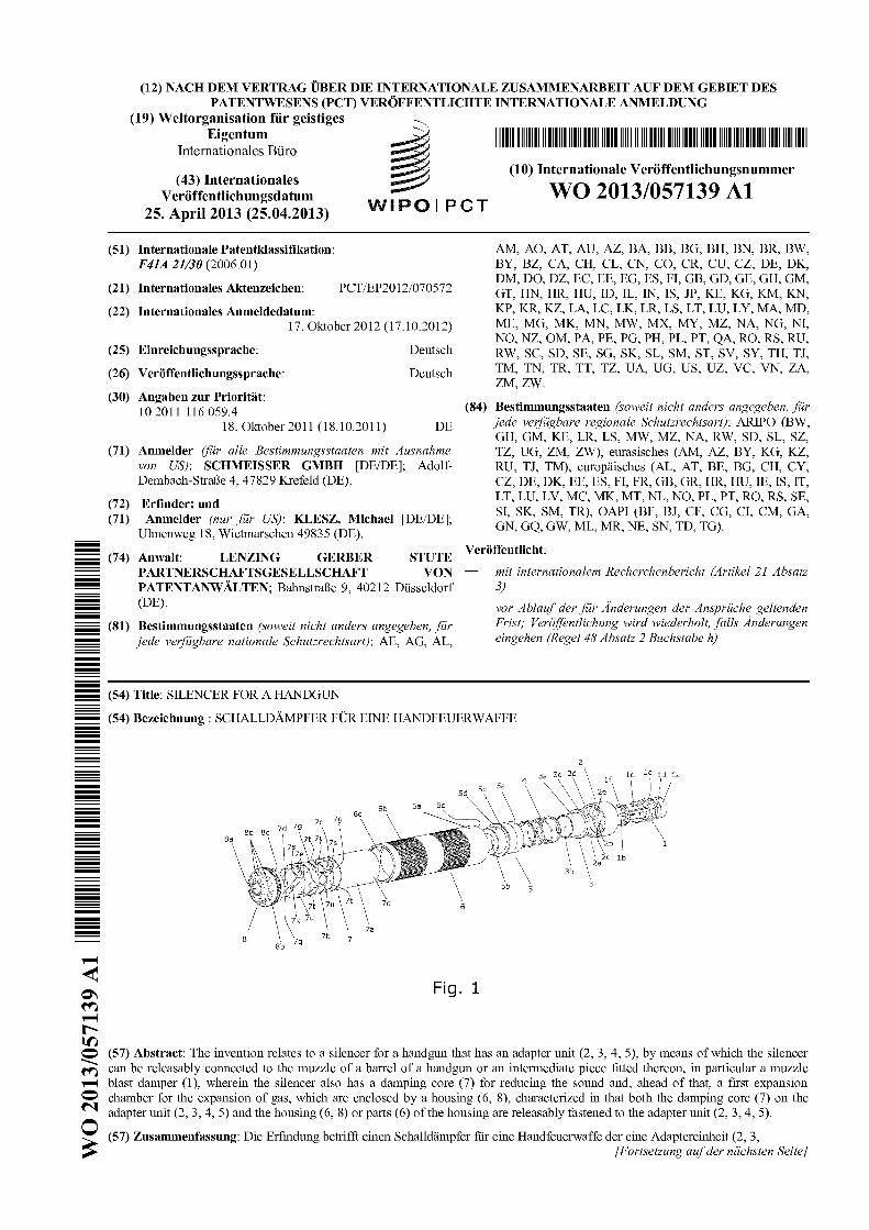
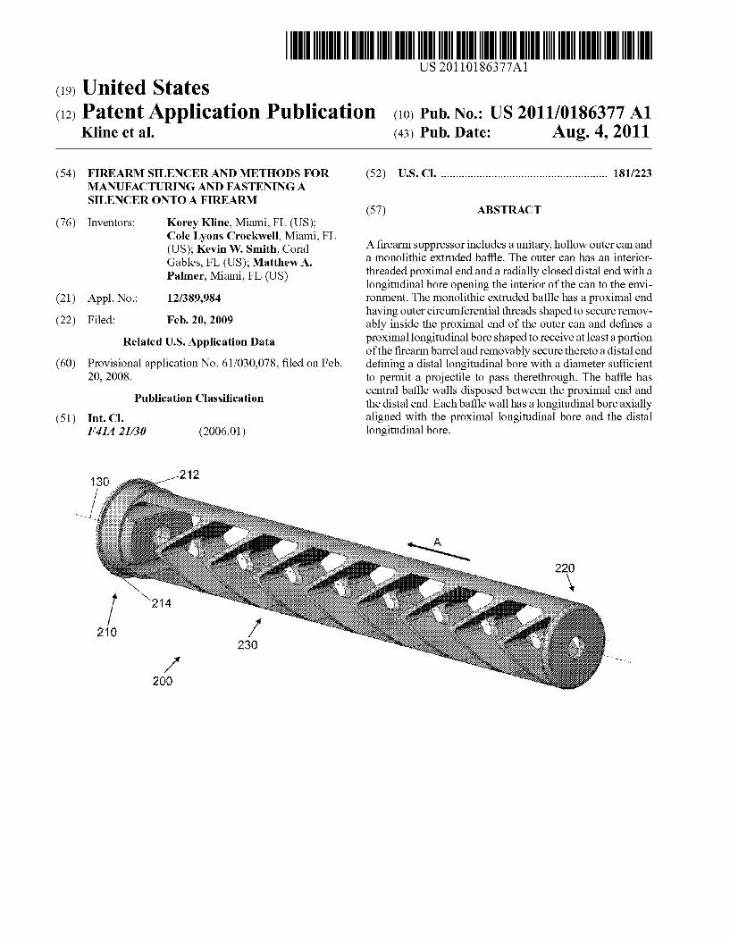
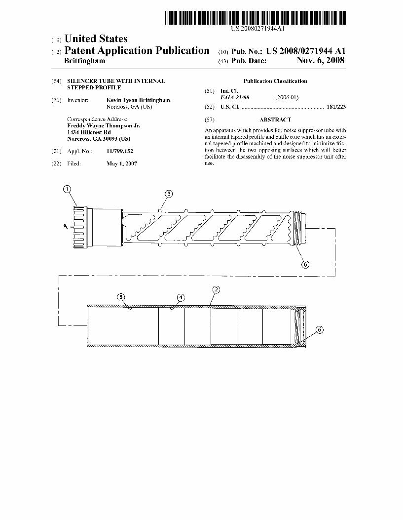
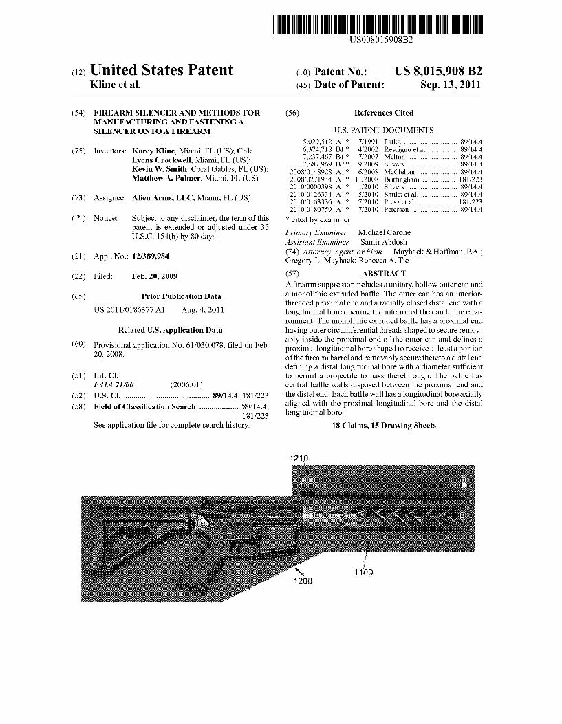
(54) FIREARM SOUND SUPPRESSOR
(71) Applicant: Silencerco, LLC, West Valley City, UT (Us)
(72) Inventors: Jonathon Shults, Sandy, UT (U S); Steven Michael Pappas, Kamas, UT (US); Harrison Holden, Sandy, UT (Us)
73 Assi nee: Silencerco, LLC, West Valle Cit ,UT 8 y y (Us)
* Notice: Sub'ect to an disclaimer, the term of this J y patent is extended or adjusted under 35 U.S.C. 154(b) by 0 days.
(21) Appl.No.: 13/891,373
(22) Filed: May 10, 2013
(65) Prior Publication Data
US 2014/0158459 A1 Jun. 12, 2014
Related US. Application Data
(63) Continuation of application No. 13/438,668, ?led on Apr. 3, 2012, noW Pat. No. 8,439,155, Which is a continuation of application No. 12/884,598, ?led on Sep. 17, 2010, noW Pat. No. 8,162,100.
(60) Provisional application No. 61/277,024, ?led on Sep. 18, 2009, provisional application No. 61/278,810, ?led on Oct. 13, 2009.
(51) 1111.0. F41A 21/00 (2006.01) F41A 21/30 (2006.01)
(52) vs. C]. CPC .................................... .. F41A 21/30 (2013.01)
USPC .......................................... .. 181/223; 89/144
(58) Field of Classi?cation Search USPC .......................................... .. 181/223; 89/144
See application ?le for complete search history.
(56) References Cited
U.S. PATENT DOCUMENTS
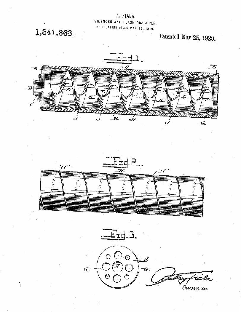
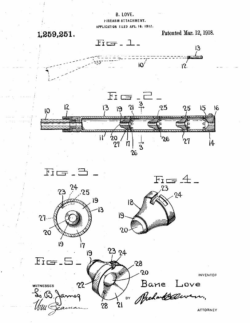
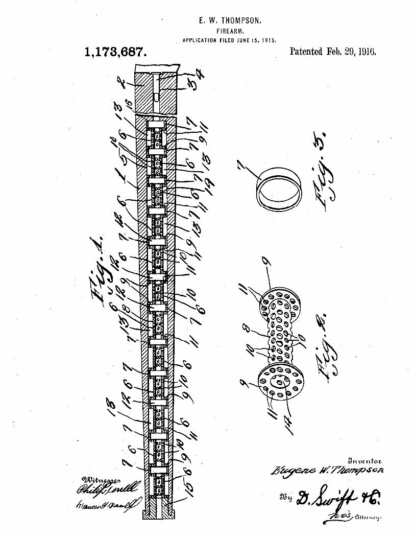
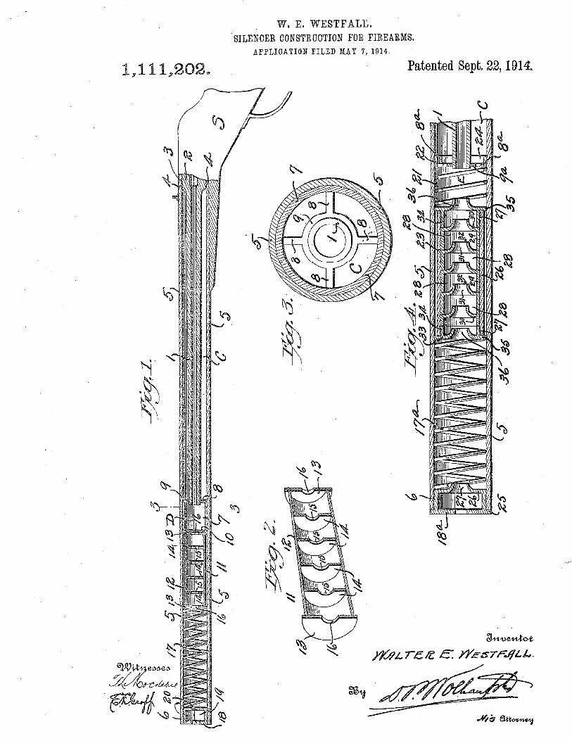
918,784 A 4/1909 Snow 1,111,202 A 9/1914 Westfall 1,394,490 A 10/1921 Giles 1,482,805 A 2/1924 Maxim 5,110,145 A 5/1992 Stewart 5,259,690 A 11/1993 Legge 6,948,415 B2 9/2005 Matthews et al. 7,237,467 B1 7/2007 Melton 7,587,969 B2 9/2009 Silvers 7,588,122 B2 9/2009 Brittingham 7,856,914 B2* 12/2010 Shults et al. ................. .. 89/144 7,874,238 B2 1/2011 Silvers
(Continued) OTHER PUBLICATIONS
United States Patent and Trademark Of?ce, “International Search Report and Written Opinion,” mailed Nov. 15, 2010, in related PCT application No. PCT/2010/049262.
Primary Examiner * Forrest M Phillips
(74) Attorney, Agent, or Firm * Durham Jones & Pinegar, P.C. Intellectual Property LaW Group
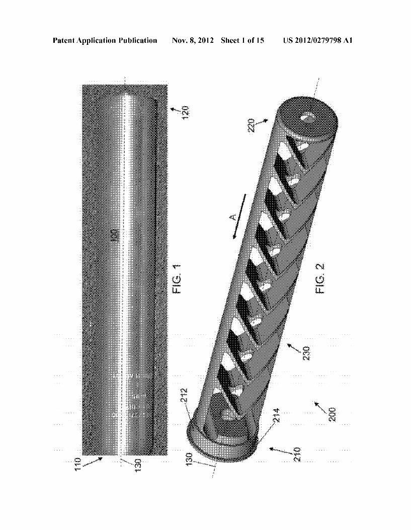
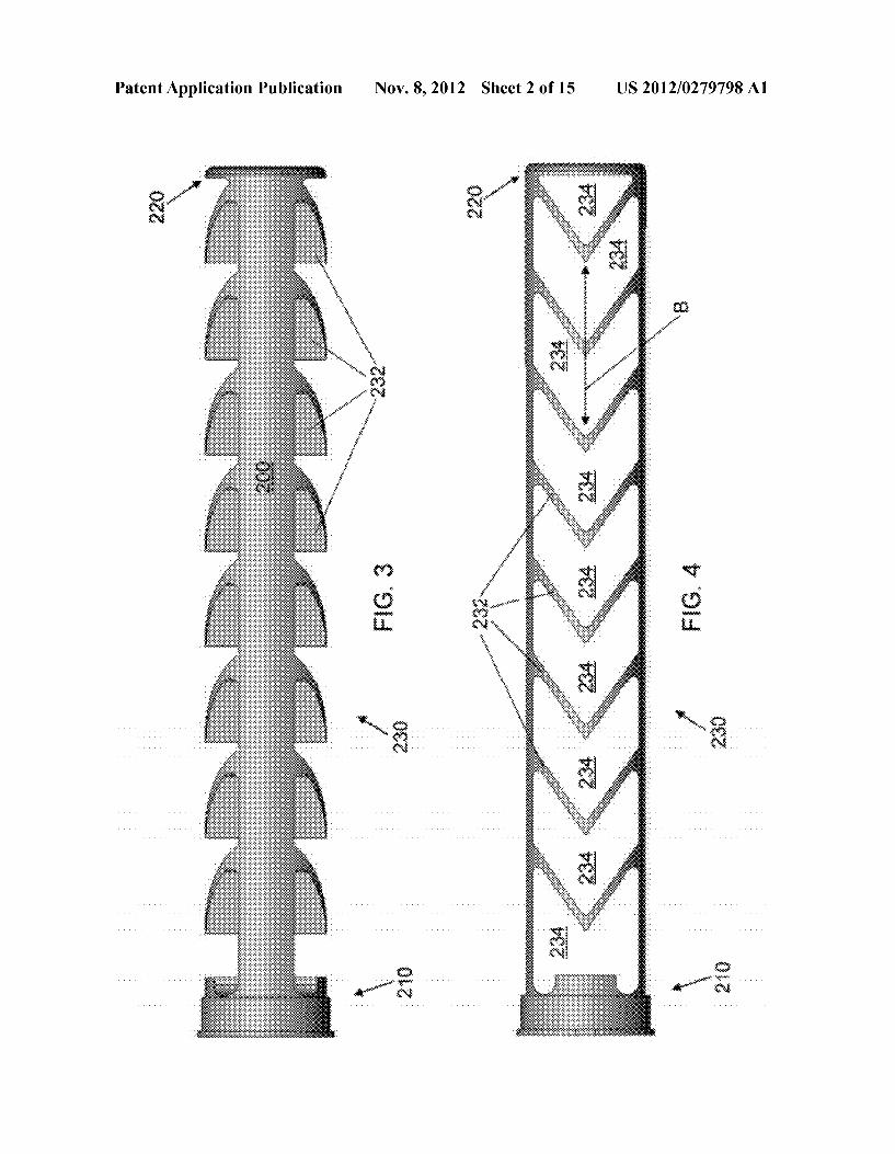
(57) ABSTRACT A suppressor for a ?rearm is provided, wherein the suppres sor can be selectively oriented relative to the ?rearm. The suppressor has an elongate body, a piston assembly and a cam assembly. A piston of the piston assembly can be ?xedly attached to the barrel of a ?rearm. An indexing ring is radially ?xed relative to the piston. The cam lever is selectively mov able between a second position, in Which the indexing ring is ?xed relative to the elongate body, and a ?rst position, in Which the indexing ring can rotate relative to the elongate body.
25 Claims, 4 Drawing Sheets
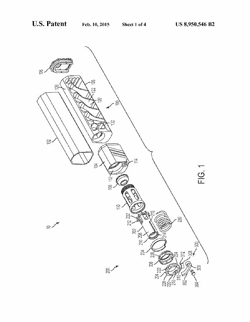
US. Patent Feb. 10, 2015 Sheet 1 0f4 US 8,950,546 B2
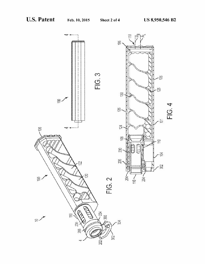
US. Patent Feb. 10, 2015 Sheet 2 0f4 US 8,950,546 B2
F26. 4
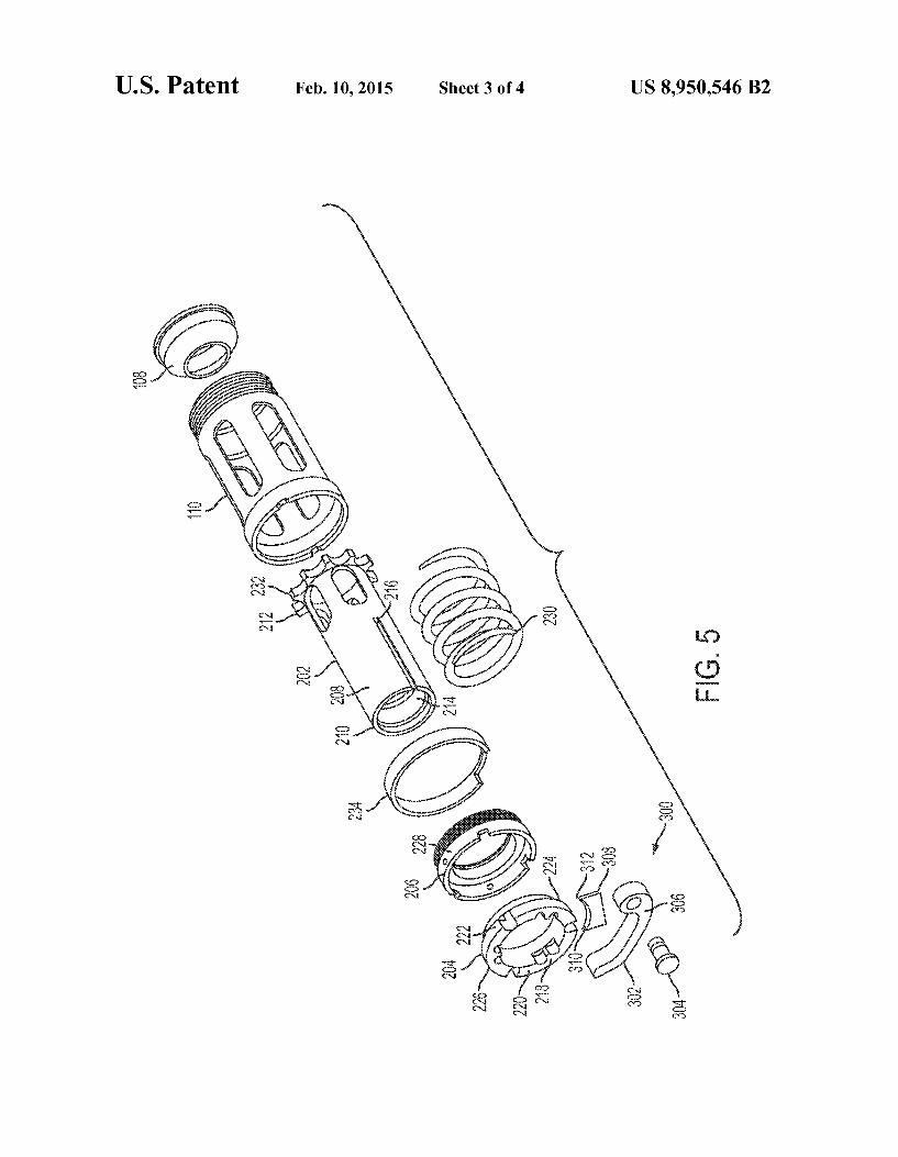
US. Patent Feb. 10, 2015 Sheet 3 0f4 US 8,950,546 B2
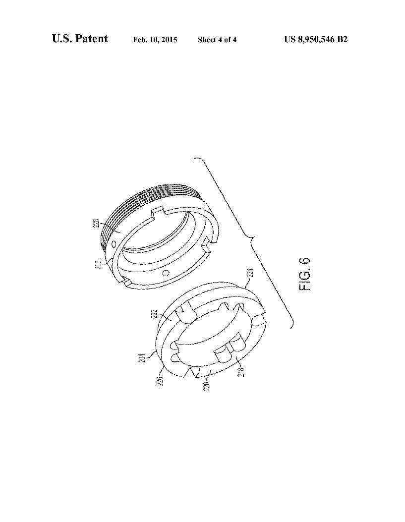
US. Patent Feb. 10, 2015 Sheet 4 0f4 US 8,950,546 B2
PEG, 6

US008424441B2
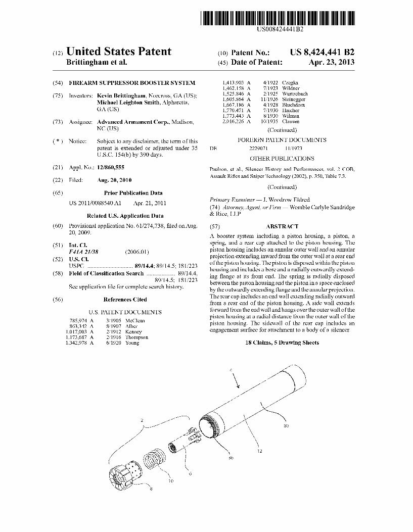
(12) United States Patent (10) Patent No.: US 8,424,441 B2 Brittingham et al. (45) Date of Patent: Apr. 23, 2013
(54) FIREARM SUPPRESSOR BOOSTER SYSTEM 1,413,903 A 4/1922 CZegka 1,462,158 A 7/1923 Wildner
(75) Inventors: Kevin Brittingham, Norcross, GA (US); 2 $225222? Michael Leighton Smith, Alpharetta, 136673186 A 4/1928 Bluehdom GA (Us) 1,770,471 A 7/1930 Hatcher
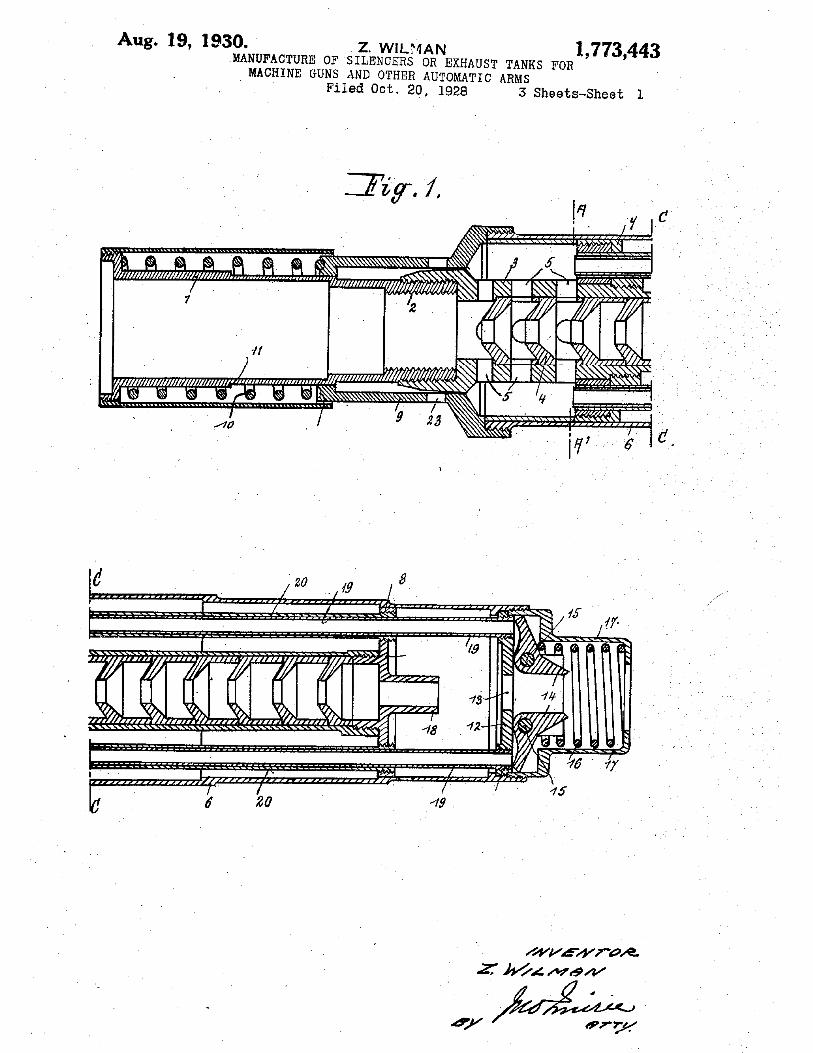
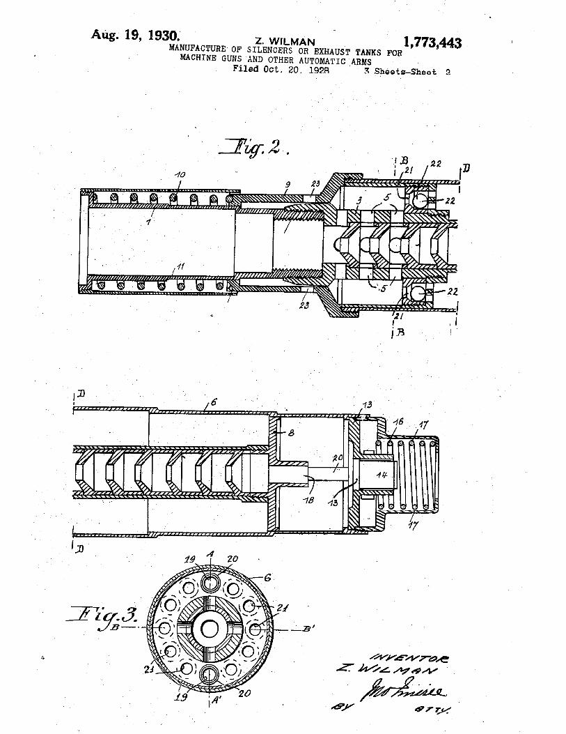
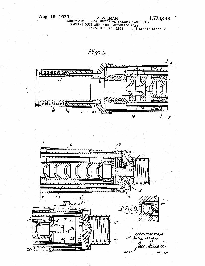
1,773,443 A 8/1930 Wilman (73) Assignee: Advanced Armament Corp., Madison, 2,016,226 A 10/ 1935 Clausen
NC (Us) (Continued)
( * ) Notice: Subject to any disclaimer, the term of this FOREIGN PATENT DOCUMENTS patent is extended or adjusted under 35 DE 2229071 11/1973
U.S.C. 154(b) by 390 days. OTHER PUBLICATIONS
(21) APP1-NO-3 12/860,555 Paulson, et al., Silencer History and Performances, vol. 2 COB, (22) F1 d A 20 2010 Assault Ri?es and Sniper Technology (2002), p. 350, Table 7.3.
1 e : ug. ,
(Continued) (65) Prior Publication Data
Us 2011/0088540 A1 A r 21 2011 Primary Examiner * J. WoodroW Eldred p ' ’ (74) Attorney, Agent, or Firm * Womble Carlyle Sandridge
Related US. Application Data & Rlce’ LLP
(60) Provisional application No. 61/274,738, ?led on Aug. (57) ABSTRACT
20’ 2009' A booster system including a piston housing, a piston, a s r1n , an a rear ca attac e to t e 1ston ous1n . e (51) Int.Cl. P'g ‘1 P hd hP' h 'gTh
F41A 21/38 (2006 01) piston housing includes an annular outer Wall and an annular (52) U 5 Cl ' projection extending inWard from the outer Wall at a rear end
U'SI',C ' 89/14-4 89/14 5_ 181/223 ofthe piston housing. The piston is disposed Within the piston 58 F, 1d "" h ’ ' ’ 89/14 4 housing and includes a bore and aradially outWardly extend
( ) 1e 0 assl ca Ion earc "" 18 1/2'23’ ing ?ange at its front end. The spring is radially disposed S 1. . ?l f 1 h h‘. ’ betWeen the piston housing and the piston in a space enclosed ee app lcanon e or Comp ete Seam lstory' by the outWardly extending ?ange and the annular projection.
(56) References Cited The rear cap includes an end Wall extending radially outWard
U.S. PATENT DOCUMENTS
785,974 A 3/1905 McClean 863,342 A 8/1907 Alber
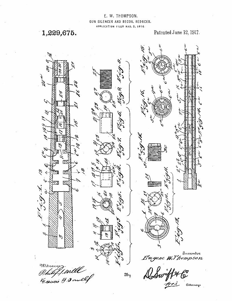
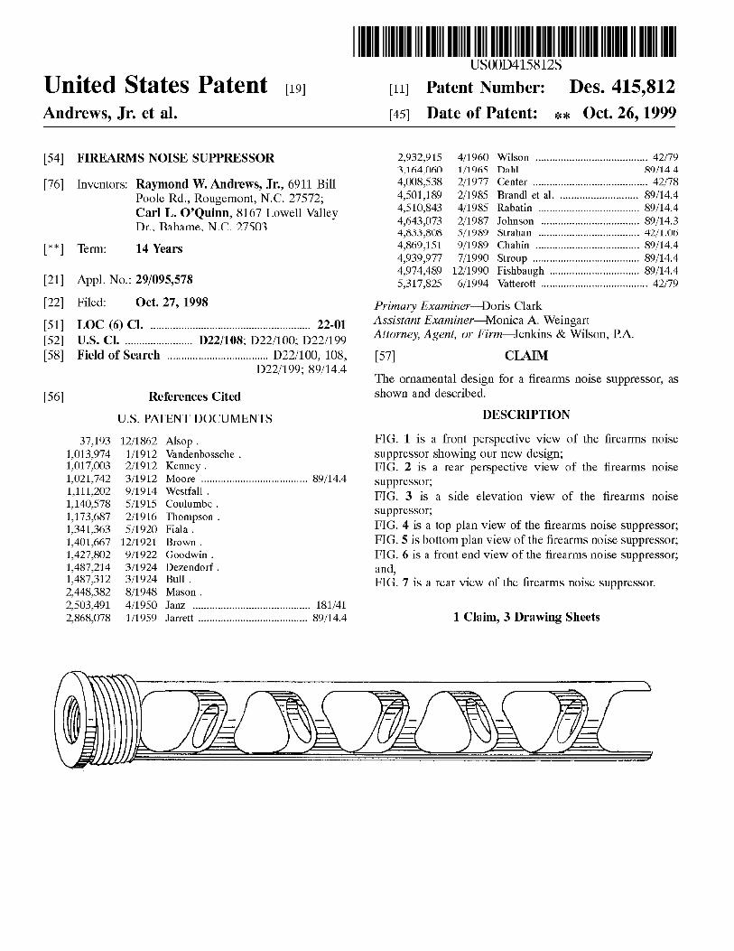
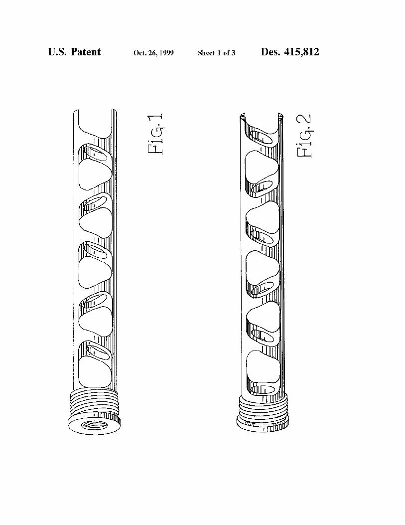
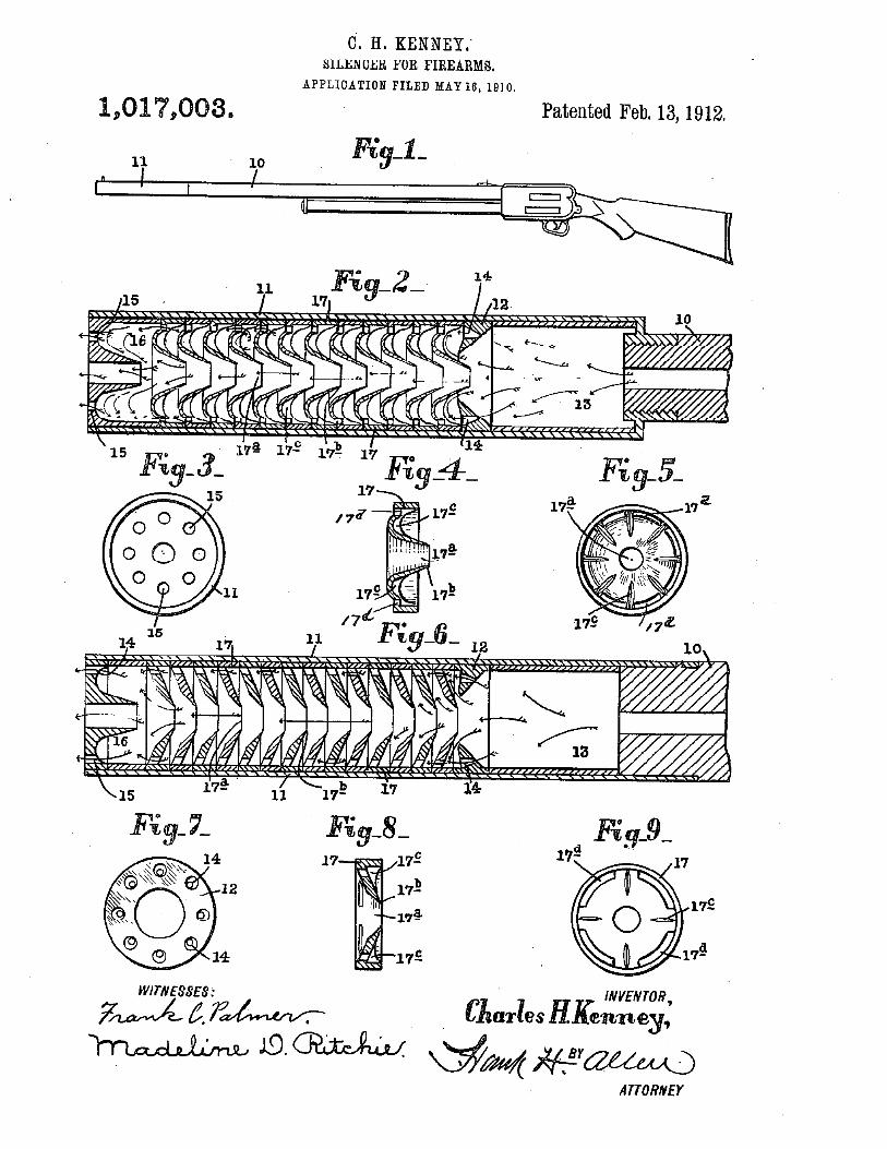
1,017,003 A 2/1912 Kenney 1,173,687 A 2/1916 Thompson 1,342,978 A 6/1920 Young
from a rear end of the piston housing. A side Wall extends forWard from the end Wall and hangs over the outer Wall of the piston housing at a radial distance from the outer Wall of the piston housing. The sideWall of the rear cap includes an engagement surface for attachment to a body of a silencer.
18 Claims, 5 Drawing Sheets
\. //3)
US 8,424,441 B2 Page 3
2006/ 0060076 A1 3/2006 Dueck et a1. OTHER PUBLICATIONS 2006/0243125 A1 11/2006 La France 2007/0095198 A1 5/2007 Dater et a1, Paulson; AAC’s Evolution-9, Suppressing hard-to-silence 9mm pis 2007/0107590 A1 5/2007 Silvers tols including Beretta 92F; Special Weapons for Military and Police;
511K331; et 31' cover and pp. 24-27; Fall 2002 issue; Harris Publications. Zoos/0083321 Al 4/2008 D?gzk et a1 Paulson; “.223 Silencers: Where We’ve been, Where We are, Where Zoos/0098880 Al 5/2008 Brugger ' We’re going!”; Special Weapons; pp. 68-75; Aug. 2004. Zoos/0121096 A1 5/2008 Haj-jar et a1 Paulson; AAC Glock 9mm Suppressors, for GLOCK 17, 19, and 26 Zoos/0148928 A1 6/2008 McClellan ' With AAC Evolution-9, Spider-2, Scorpionl; Combat Handguns; Zoos/0156183 A1 7/2008 Brittingham cover and pp. 34-39; Jun. 2006 issue; Harris Publications. Zoos/0271944 A1 11/2008 Brittingham AAC Evolution-0 .9MM Shootout and Pistol Trials, Oct. 12, 2007 2009/0050403 A1 2/2009 Brittingham http://WWW.silencerresearch.com/9mmishootoutiandipistolitri 2010/02g1747 A1 11/2010 Anderson als.htm and http://Web.archive.org/Web/~/http://WWW.silencer-re 2010/02941 18 A 1 1 1/201() Honobagyi search.com/9mmishootoutiandipistolitrials.htrn and http//Web. 2010/0313743 A1 12/2010 Dueck et a1, archiveorg/web/200710121508481http://silencerresearchcon? 201 1/ 0036233 A1 2/201 1 Degroat 9misho0t0utiandipistolit. 201 1/00 561 11 A1 3/201 1 Brittingham Multimount System. (2008) Retrieved from hup://WWW.gem-tech. 201 1/ 0056364 A1 3/2011 Kennedy et al. com/MultiMounthtml. 2011/0061966 A1 3/2011 Brittingham 2012/0145478 A1 6/2012 Brittingham * cited by examiner
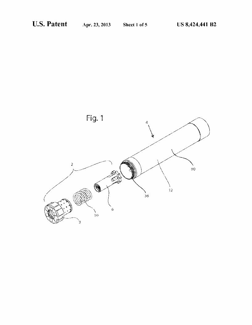
US. Patent Apr. 23, 2013 Sheet 1 of5 US 8,424,441 B2
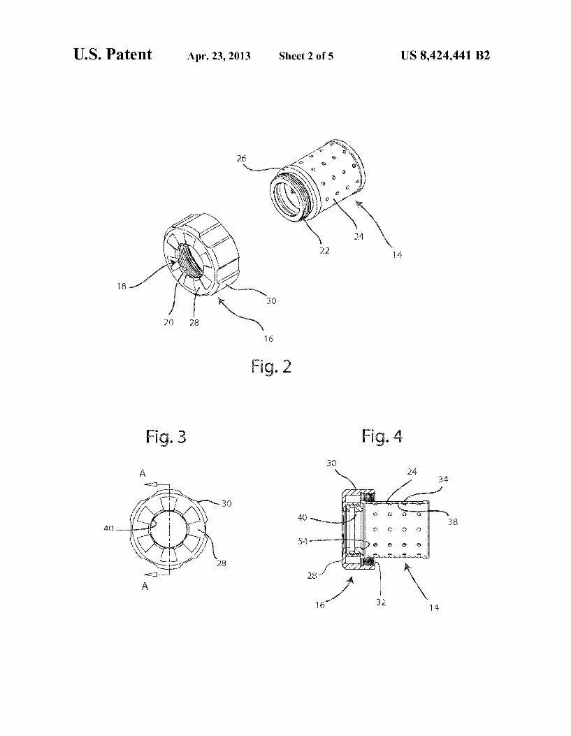
US. Patent Apr. 23, 2013 Sheet 2 of5 US 8,424,441 B2
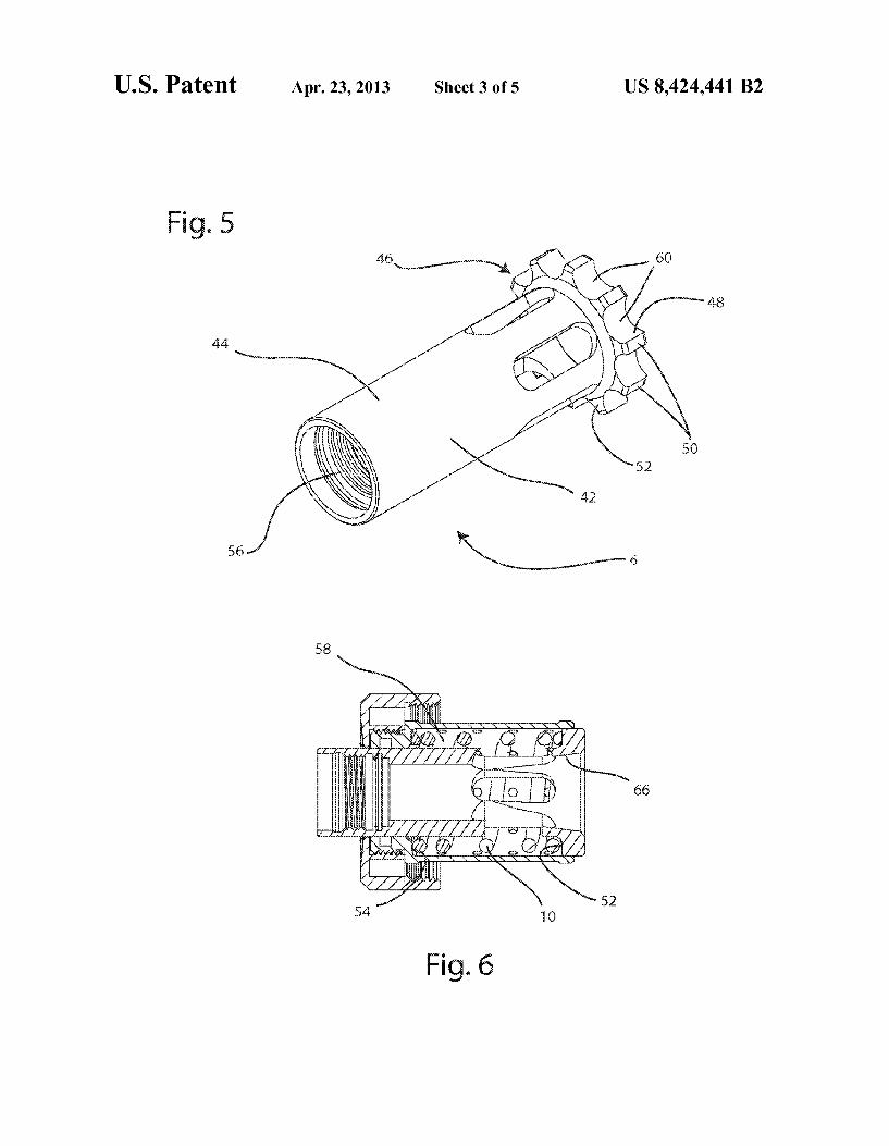
US. Patent Apr. 23, 2013 Sheet 3 of5 US 8,424,441 B2
58
a ‘ 2 2 ,
I-IQT/ 66
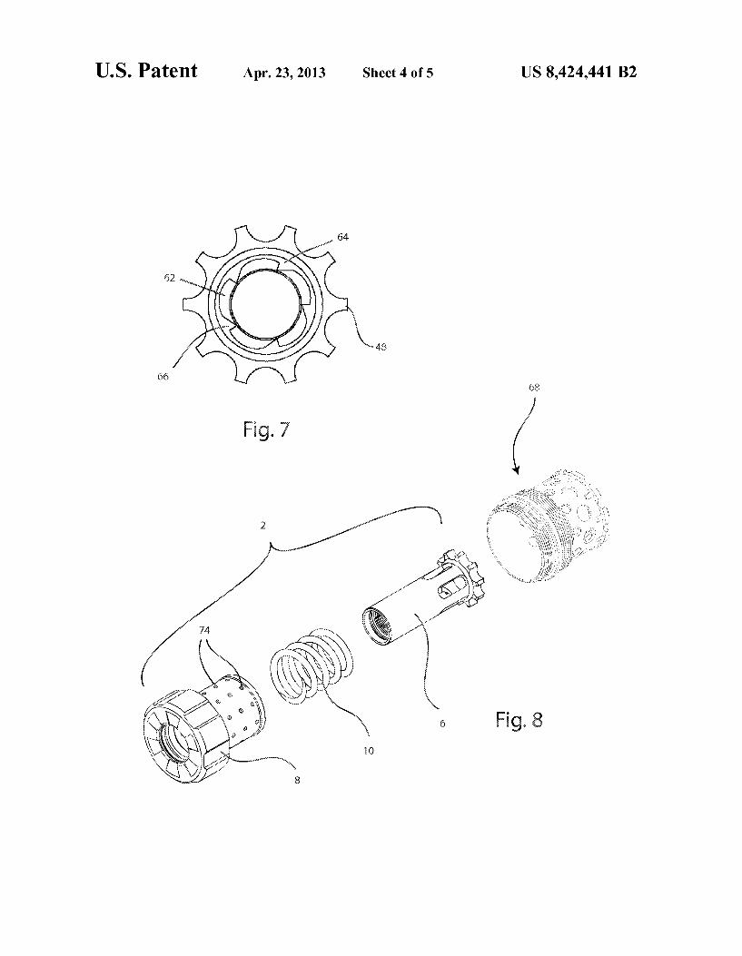
US. Patent Apr. 23, 2013 Sheet 4 of5 US 8,424,441 B2
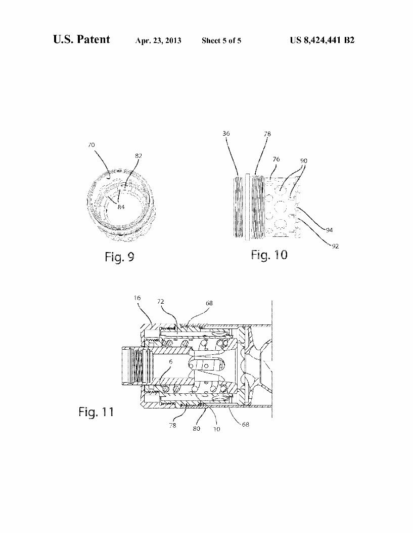
US. Patent Apr. 23, 2013 Sheet 5 of5 US 8,424,441 B2


![US00543417OA United States Patent [19] [11] Patent … · US00543417OA United States Patent [19] [11] Patent Number: 5 a 434 ... N0 Drawings . 5,434, 170 1 ... These have included](https://img.pdfslide.us/doc/110x75/5b0a37917f8b9ac7678c08c1/-us00543417oa-united-states-patent-19-11-patent-united-states-patent-19-11.jpg)