Embed Size (px)
Citation preview
Session One: The role antennas play in a MIMO link
Africa Radio Comms Conference Johannesburg 2014 www.poynting.co.za
1
Session One
The role antennas play in a MIMO link
Dr Andre Fourie CEO, Poynting Antennas
Abstract (All headings - Arial 14, BOLD)
MIMO, in conjunction with SDMA, is a technology that is used in 4G networks to increase the data throughput of a wireless network. The antennas used in the link have a direct correlation with the performance of a MIMO link. The antenna attributes that play the dominant performance enhancing role in MIMO links are the radiation pattern and the polarization.
The nature of the indoor and outdoor channels is discussed and it is shown that a MIMO link performs far better in outdoor channels; hence the use of outdoor antenna installations is emphasized.
Introduction
One of the primary drives for contemporary wireless communication systems is to increase the rate of throughput. MIMO, which is used in Wi-Fi (IEEE 802.11), WiMAX (IEEE 802.16e) and 3GPP LTE, is one of the techniques used to achieve this aim. This tutorial describes how MIMO (in conjunction with SDMA, spacial division multiplexing) works and the importance antennas play in enabling the technology. The attributes of an antenna that contribute directly to the performance of a MIMO channel include the radiation pattern and its polarization properties. These antenna parameters are introduced and discussed. The properties of the channel determine the efficacy of the MIMO link. Various possible MIMO channels are identified such as cluttered outdoor channels and channels that terminate indoors. It is shown that channels that terminate outdoors are far more data-throughput friendly than indoor channels and hence the use of outdoor antennas (where possible) is stressed.
Antennas and channels
Antennas play a pivotal role in a MIMO link. The two most important characteristics of an antenna (as far as MIMO is concerned) are the radiation patterns and its polarization. These characteristics will be discussed in the following sections.
Radiation patterns
From a transmission point of view, the radiation pattern of an antenna is a graphical representation of how energy that is fed into the antenna is radiated into space.
An example of a radiation pattern is given in Figure 1.
Session One: The role antennas play in a MIMO link
Africa Radio Comms Conference Johannesburg 2014 www.poynting.co.za
2
Figure 1: Example of a radiation pattern
The radiation pattern of antenna is the same for both reception and transmission. When an antenna is used for reception, the radiation pattern can be interpreted as the antennas ability to receive a radio signal from various directions.
Polarisation
The polarisation of an antenna is defined in terms of the orientation that an antenna radiates or receives an electric field (as opposed to the magnetic field). This orientation is often referred to with respect to the earth.
For example, an antenna that is susceptible to electric fields that are vertically oriented with respect to the earth is considered to be vertically polarised. Rotate that antenna by 90° about the axis that it radiates and that same antenna will then be horizontally polarised. In such an orientation it will no longer receive vertically polarised electric fields. Typically, an antenna that is mounted perpendicular to the orientation of the electric field will have a gain about 20dB below that when the antenna is in the same orientation as the electric field.
This property of an antenna is exploited by the MIMO technology to separate two streams of data that are modulated onto radio waves at the same frequency.
An electromagnetic wave can also be circularly polarised. In this case, the electric field rotates about the axis of propagation. So, rather than being in a fixed orientation with respect to the earth, the orientation of a circularly polarised electric field is continuously changing. If a linearly polarised antenna is used to receive a circularly polarised signal, the effective gain of the antenna will be half that compared to when it is receiving a linearly polarised signal. Expressed in decibels, the effective gain would be 3dB lower than the linear gain.
Channels
In the communication literature, reference is often made of the concept of a channel. A channel can be considered to be the path between a transmitter and a receiver for a given frequency range on which data is modulated (including the antennas at either end of the link).
Session One: The role antennas play in a MIMO link
Africa Radio Comms Conference Johannesburg 2014 www.poynting.co.za
3
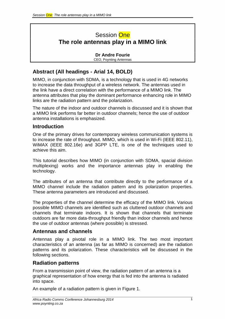
An example of a channel is the free space (unobstructed channel) shown in Figure 2.
Figure 2: The free space channel
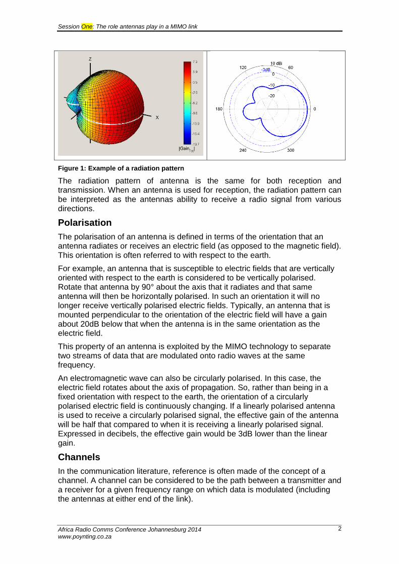
An electromagnetic wave is generated at the transmitter and propagates unimpeded through space to the receiver. A more complicated channel could involve an object from which there is a reflection.
Figure 3: A channel with a single reflection
An urban channel has multiple objects and hence many possible reflections.
Session One: The role antennas play in a MIMO link
Africa Radio Comms Conference Johannesburg 2014 www.poynting.co.za
4
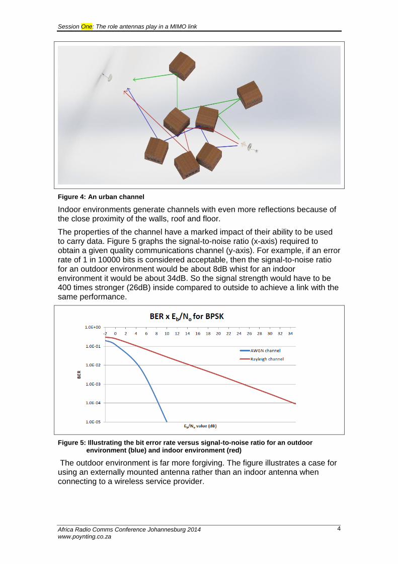
Figure 4: An urban channel
Indoor environments generate channels with even more reflections because of the close proximity of the walls, roof and floor.
The properties of the channel have a marked impact of their ability to be used to carry data. Figure 5 graphs the signal-to-noise ratio (x-axis) required to obtain a given quality communications channel (y-axis). For example, if an error rate of 1 in 10000 bits is considered acceptable, then the signal-to-noise ratio for an outdoor environment would be about 8dB whist for an indoor environment it would be about 34dB. So the signal strength would have to be 400 times stronger (26dB) inside compared to outside to achieve a link with the same performance.
Figure 5: Illustrating the bit error rate versus signal-to-noise ratio for an outdoor environment (blue) and indoor environment (red)
The outdoor environment is far more forgiving. The figure illustrates a case for using an externally mounted antenna rather than an indoor antenna when connecting to a wireless service provider.
Session One: The role antennas play in a MIMO link
Africa Radio Comms Conference Johannesburg 2014 www.poynting.co.za
5
MIMO (multiple input – multiple output)
MIMO is an acronym that stands for multiple input – multiple output. It is a term used to describe communications links where multiple transmitters and multiple receivers are used at each end of a link.
The multiple transmitters and receivers can be used in a number of ways to either improve the reliability of the link or to increase the data rate through the link, or both.
This tutorial is going to concentrate on increasing the data rate through a channel using a technique called SDMA (spacial division multiplexing). Often SDMA is defined as spacial division multiple access; however multiplexing is, in my opinion, a better description of the process.
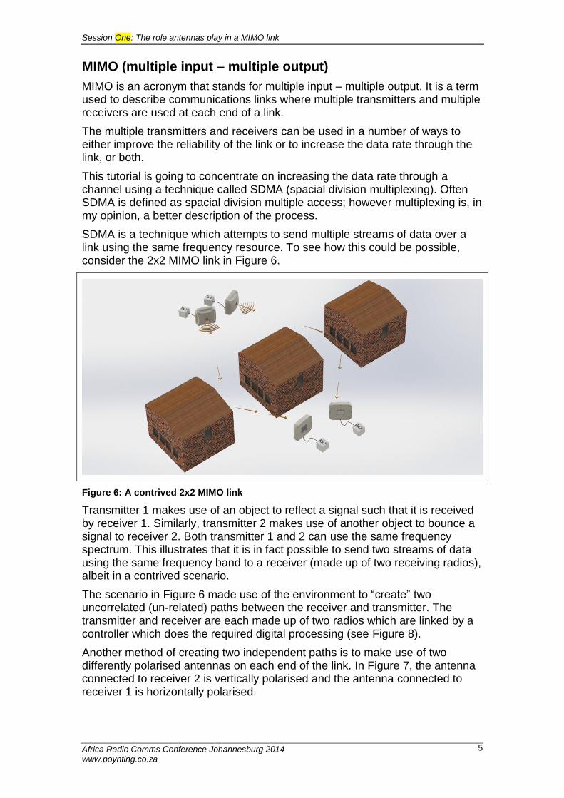
SDMA is a technique which attempts to send multiple streams of data over a link using the same frequency resource. To see how this could be possible, consider the 2x2 MIMO link in Figure 6.
Figure 6: A contrived 2x2 MIMO link
Transmitter 1 makes use of an object to reflect a signal such that it is received by receiver 1. Similarly, transmitter 2 makes use of another object to bounce a signal to receiver 2. Both transmitter 1 and 2 can use the same frequency spectrum. This illustrates that it is in fact possible to send two streams of data using the same frequency band to a receiver (made up of two receiving radios), albeit in a contrived scenario.
The scenario in Figure 6 made use of the environment to “create” two uncorrelated (un-related) paths between the receiver and transmitter. The transmitter and receiver are each made up of two radios which are linked by a controller which does the required digital processing (see Figure 8).
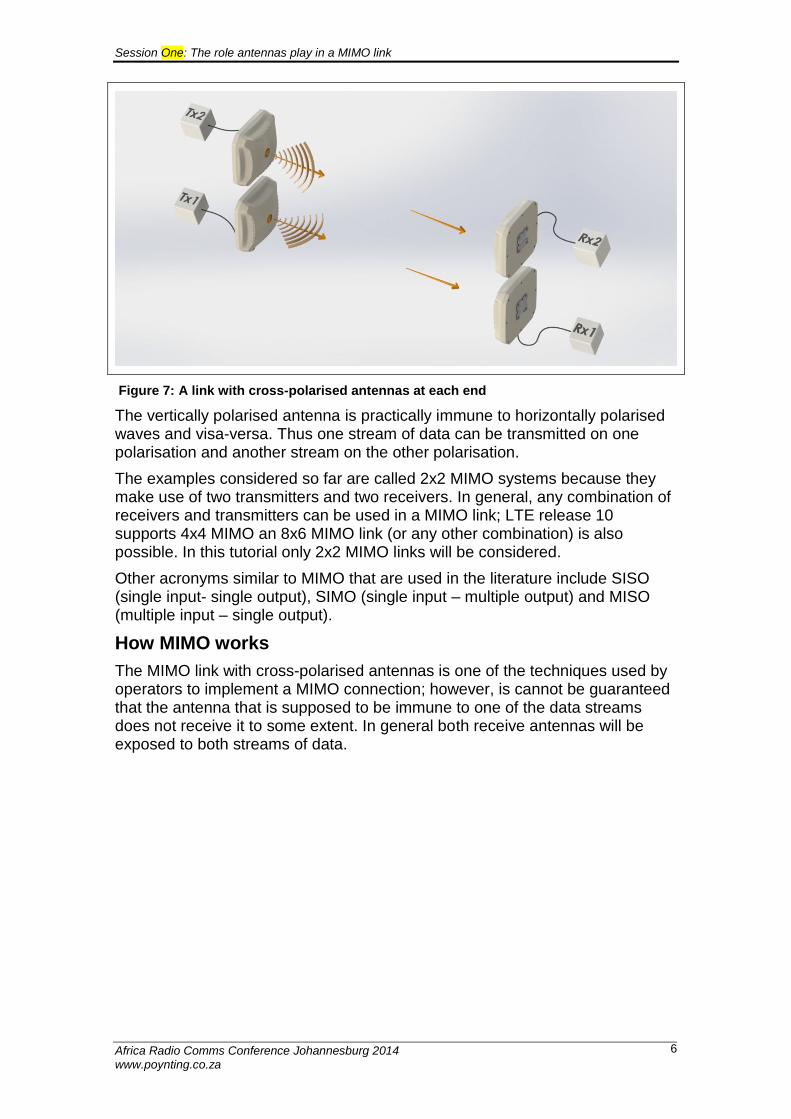
Another method of creating two independent paths is to make use of two differently polarised antennas on each end of the link. In Figure 7, the antenna connected to receiver 2 is vertically polarised and the antenna connected to receiver 1 is horizontally polarised.
Session One: The role antennas play in a MIMO link
Africa Radio Comms Conference Johannesburg 2014 www.poynting.co.za
6
Figure 7: A link with cross-polarised antennas at each end
The vertically polarised antenna is practically immune to horizontally polarised waves and visa-versa. Thus one stream of data can be transmitted on one polarisation and another stream on the other polarisation.
The examples considered so far are called 2x2 MIMO systems because they make use of two transmitters and two receivers. In general, any combination of receivers and transmitters can be used in a MIMO link; LTE release 10 supports 4x4 MIMO an 8x6 MIMO link (or any other combination) is also possible. In this tutorial only 2x2 MIMO links will be considered.
Other acronyms similar to MIMO that are used in the literature include SISO (single input- single output), SIMO (single input – multiple output) and MISO (multiple input – single output).
How MIMO works
The MIMO link with cross-polarised antennas is one of the techniques used by operators to implement a MIMO connection; however, is cannot be guaranteed that the antenna that is supposed to be immune to one of the data streams does not receive it to some extent. In general both receive antennas will be exposed to both streams of data.
Session One: The role antennas play in a MIMO link
Africa Radio Comms Conference Johannesburg 2014 www.poynting.co.za
7
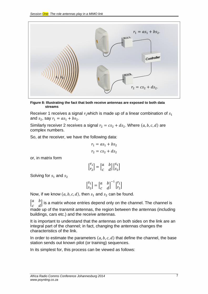
Figure 8: Illustrating the fact that both receive antennas are exposed to both data streams
Receiver 1 receives a signal 𝑟1which is made up of a linear combination of 𝑠1 and 𝑠2, say 𝑟1 = 𝑎𝑠1 + 𝑏𝑠2.
Similarly receiver 2 receives a signal 𝑟2 = 𝑐𝑠2 + 𝑑𝑠2. Where (𝑎, 𝑏, 𝑐, 𝑑) are complex numbers.
So, at the receiver, we have the following data:
𝑟1 = 𝑎𝑠1 + 𝑏𝑠2
𝑟2 = 𝑐𝑠2 + 𝑑𝑠2
or, in matrix form
[𝑟1
𝑟2] = [
𝑎 𝑏𝑐 𝑑
] [𝑠1
𝑠2]
Solving for 𝑠1 and 𝑠2
[𝑠1
𝑠2] = [
𝑎 𝑏𝑐 𝑑
]−1
[𝑟1
𝑟2]
Now, if we know (𝑎, 𝑏, 𝑐, 𝑑), then 𝑠1 and 𝑠2 can be found.
[𝑎 𝑏𝑐 𝑑
] is a matrix whose entries depend only on the channel. The channel is
made up of the transmit antennas, the region between the antennas (including buildings, cars etc.) and the receive antennas.
It is important to understand that the antennas on both sides on the link are an integral part of the channel; in fact, changing the antennas changes the characteristics of the link.
In order to estimate the parameters (𝑎, 𝑏, 𝑐, 𝑑) that define the channel, the base station sends out known pilot (or training) sequences.
In its simplest for, this process can be viewed as follows:
𝑟1 = 𝑎𝑠1 + 𝑏𝑠2.
𝑟2 = 𝑐𝑠2 + 𝑑𝑠2.
𝑠1 𝑠2
Session One: The role antennas play in a MIMO link
Africa Radio Comms Conference Johannesburg 2014 www.poynting.co.za
8
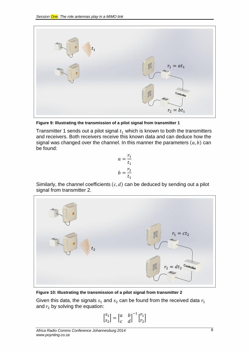
Figure 9: Illustrating the transmission of a pilot signal from transmitter 1
Transmitter 1 sends out a pilot signal 𝑡1 which is known to both the transmitters and receivers. Both receivers receive this known data and can deduce how the
signal was changed over the channel. In this manner the parameters (𝑎, 𝑏) can be found:
𝑎 =𝑟1
𝑡1
𝑏 =𝑟2
𝑡1
Similarly, the channel coefficients (𝑐, 𝑑) can be deduced by sending out a pilot signal from transmitter 2.
Figure 10: Illustrating the transmission of a pilot signal from transmitter 2
Given this data, the signals 𝑠1 and 𝑠2 can be found from the received data 𝑟1
and 𝑟2 by solving the equation:
[𝑠1
𝑠2] = [
𝑎 𝑏𝑐 𝑑
]−1
[𝑟1
𝑟2]
𝑡1
𝑟1 = 𝑎𝑡1
𝑟2 = 𝑏𝑡1
𝑡2
𝑟1 = 𝑐𝑡2
𝑟2 = 𝑑𝑡2
Session One: The role antennas play in a MIMO link
Africa Radio Comms Conference Johannesburg 2014 www.poynting.co.za
9
These coefficients can be used to determine the transmitted signals as long as the channel does not change too much between the event of measuring the channel and sending the data.
Earlier it was mentioned that the outdoor environment was far more data-throughput friendly that the indoor environment. One of the reasons is that the indoor environment changes very rapidly with time whereas the outdoor environment is more stable. This is another motivating factor for using outdoor antennas for wireless links.
The above procedure roughly describes the manner in which the MIMO technology is able to send multiple streams of data over a given frequency band at the same time.
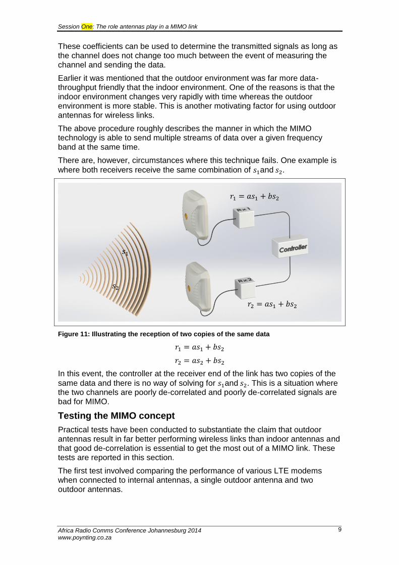
There are, however, circumstances where this technique fails. One example is
where both receivers receive the same combination of 𝑠1and 𝑠2.
Figure 11: Illustrating the reception of two copies of the same data
𝑟1 = 𝑎𝑠1 + 𝑏𝑠2
𝑟2 = 𝑎𝑠2 + 𝑏𝑠2
In this event, the controller at the receiver end of the link has two copies of the
same data and there is no way of solving for 𝑠1and 𝑠2. This is a situation where the two channels are poorly de-correlated and poorly de-correlated signals are bad for MIMO.
Testing the MIMO concept
Practical tests have been conducted to substantiate the claim that outdoor antennas result in far better performing wireless links than indoor antennas and that good de-correlation is essential to get the most out of a MIMO link. These tests are reported in this section.
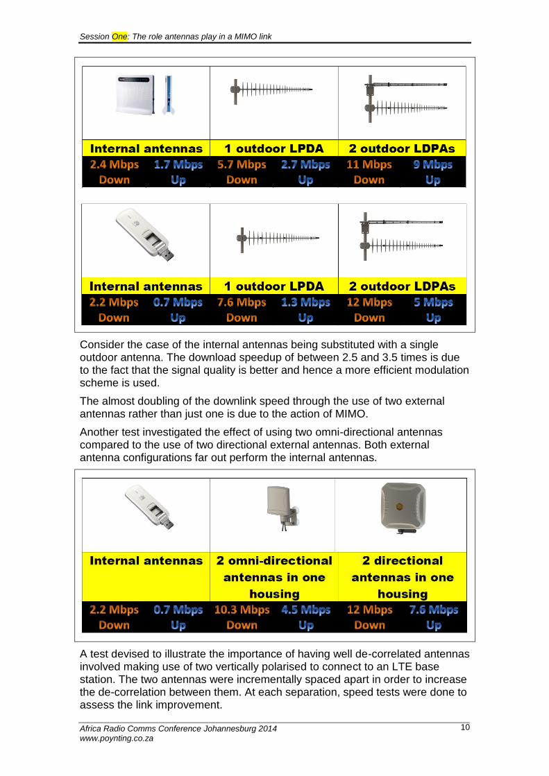
The first test involved comparing the performance of various LTE modems when connected to internal antennas, a single outdoor antenna and two outdoor antennas.
𝑟1 = 𝑎𝑠1 + 𝑏𝑠2
𝑟2 = 𝑎𝑠1 + 𝑏𝑠2
𝑠1
𝑠2
Session One: The role antennas play in a MIMO link
Africa Radio Comms Conference Johannesburg 2014 www.poynting.co.za
10
Consider the case of the internal antennas being substituted with a single outdoor antenna. The download speedup of between 2.5 and 3.5 times is due to the fact that the signal quality is better and hence a more efficient modulation scheme is used.
The almost doubling of the downlink speed through the use of two external antennas rather than just one is due to the action of MIMO.
Another test investigated the effect of using two omni-directional antennas compared to the use of two directional external antennas. Both external antenna configurations far out perform the internal antennas.
A test devised to illustrate the importance of having well de-correlated antennas involved making use of two vertically polarised to connect to an LTE base station. The two antennas were incrementally spaced apart in order to increase the de-correlation between them. At each separation, speed tests were done to assess the link improvement.
Session One: The role antennas play in a MIMO link
Africa Radio Comms Conference Johannesburg 2014 www.poynting.co.za
11
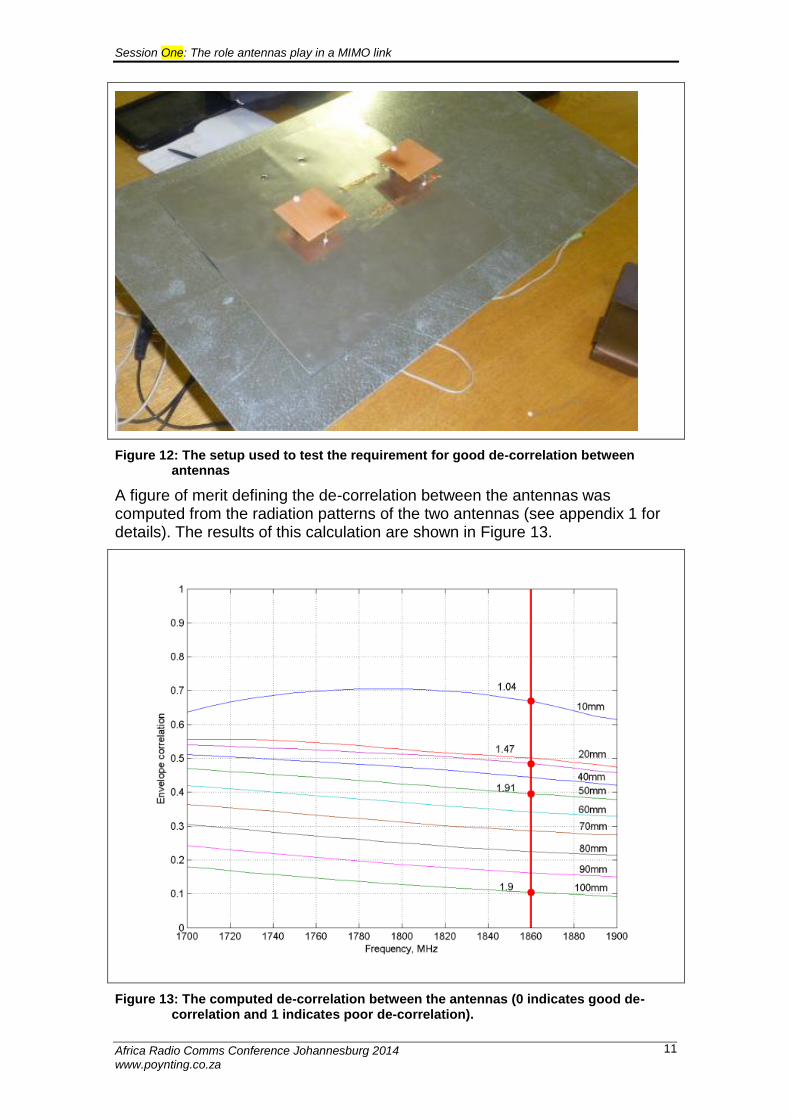
Figure 12: The setup used to test the requirement for good de-correlation between antennas
A figure of merit defining the de-correlation between the antennas was computed from the radiation patterns of the two antennas (see appendix 1 for details). The results of this calculation are shown in Figure 13.
Figure 13: The computed de-correlation between the antennas (0 indicates good de-correlation and 1 indicates poor de-correlation).
Session One: The role antennas play in a MIMO link
Africa Radio Comms Conference Johannesburg 2014 www.poynting.co.za
12
Each line in the graph indicates the de-correlation between antennas for a given antenna separation (varying from 10mm to 100mm). The red vertical line indicates the frequency of the LTE signal and the red dots on this line show the MIMO speedup. The MIMO speedup shows the speed improvement when using two antennas compared to using a single antenna (in other words, a measure of the effect of using MIMO).
So, when the antennas were spaced 10mm apart, it made little difference whether one or two antennas were used – using two antennas resulted in download speeds that were 1.04 times faster than using a single antenna.
As the antennas were spaced further apart, so the de-correlation improved and also the speedup.
It is seen that no improvement was made once the de-correlation of 0.5 was reached.
Conclusion
MIMO incorporating SDMA is a technology that is used in LTE, WiMax and Wi-Fi. A brief description of how SDMA with works with MIMO was given.
It was emphasised that making use of external antennas, even in a non-MIMO technology (such as 3G), makes a massive difference to the data throughput. If MIMO is used and the two antennas are well de-correlated then the data throughput can be doubled (when compared to using a single external antenna).
Session One: The role antennas play in a MIMO link
Africa Radio Comms Conference Johannesburg 2014 www.poynting.co.za
13
Appendix 1: PREDICTING THE LTE PERFORMANCE OF AN ANTENNA BY
MEANS OF RADIATION PATTERN ANALYSIS
Introduction
The performance of a MIMO system is dependent on the propagation characteristics of the environment and the characteristics of the antennas. The environment could vary between an indoor scenario where the angular spread of scattered field is large, to an outdoor uncluttered environment where the angular spread is more confined. In both cases the ideal antenna (for good diversity performance) should have radiation patterns with low correlation over the possible angles of arrival of multipath components.
The envelope correlation between two radiation patterns 𝐹1(𝐸𝜃, 𝐸𝜙) and
𝐹2(𝐸𝜃, 𝐸𝜙) is given by:
𝜌𝑒 =[∫ (
𝑋1 + 𝑋
𝐸1𝜃𝐸2𝜃∗ 𝑃𝜃 +
11 + 𝑋
𝐸1𝜙𝐸2𝜙∗ 𝑃𝜙) 𝑑Ω
Ω]
2
∫ (𝑋
1 + 𝑋𝐸1𝜃𝐸1𝜃
∗ 𝑃𝜃 +1
1 + 𝑋𝐸1𝜙𝐸1𝜙
∗ 𝑃𝜙) 𝑑ΩΩ
× ∫ (𝑋
1 + 𝑋𝐸2𝜃𝐸2𝜃
∗ 𝑃𝜃 +1
1 + 𝑋𝐸2𝜙𝐸2𝜙
∗ 𝑃𝜙) 𝑑ΩΩ
Where:
Ω(𝜃, 𝜙) represents the spatial angle
E1θ, E2θ, E1ϕ, E2ϕare the complex envelopes of the components of the
field patterns for each port of the antenna
𝑃𝜃, 𝑃𝜙 are the probability distributions of the power incident on the
antenna in the two polarisations.
𝑋 is the cross polarisation power ratio, which is defined as the mean received power in the vertical to the horizontal polarisation.
In an indoor environment there are many objects from which the signal may scatter; hence the signals impinge upon the antenna isotropically. In such a
scenario, Pθ and Pϕ are equal to 1 4𝜋⁄ indicating that there is an equal probability
of a signal arriving from any angle (when compared to any other angle).
In an outdoor environment the range of angles from which a signal is likely to come is limited to the antenna azimuth plane over a smallish range of elevation angles. In this case suitable functions for Pθ and Pϕ have to be chosen to
represent such a distribution. Knudsen [2] found that an elliptical distribution function for Pθ and Pϕ fits experimental data reasonably well.
Vaughan [ 1] has derived a rule-of-thumb that states that good diversity operation is possible when the envelope correlation of the patterns of an antenna is less than 0.5.
Computing the envelope correlation for a prospective LTE antenna will enable a figure of merit to be assigned to the antenna indicating its efficacy in an LTE link.
Canonical case studies
Matlab code was written to evaluate the expression for the radiation pattern envelope correlation. In order to ensure that the function was correctly coded canonical studies taken from the literature were repeated.
Session One: The role antennas play in a MIMO link
Africa Radio Comms Conference Johannesburg 2014 www.poynting.co.za
14
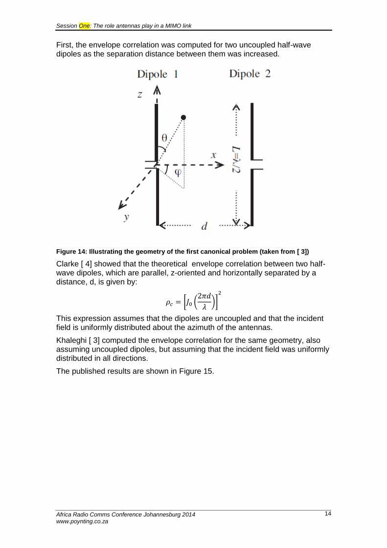
First, the envelope correlation was computed for two uncoupled half-wave dipoles as the separation distance between them was increased.
Figure 14: Illustrating the geometry of the first canonical problem (taken from [ 3])
Clarke [ 4] showed that the theoretical envelope correlation between two half-wave dipoles, which are parallel, z-oriented and horizontally separated by a distance, d, is given by:
𝜌𝑐 = [𝐽0 (2𝜋𝑑
𝜆)]
2
This expression assumes that the dipoles are uncoupled and that the incident field is uniformly distributed about the azimuth of the antennas.
Khaleghi [ 3] computed the envelope correlation for the same geometry, also assuming uncoupled dipoles, but assuming that the incident field was uniformly distributed in all directions.
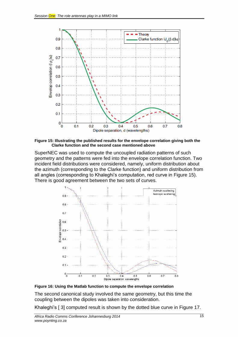
The published results are shown in Figure 15.
Session One: The role antennas play in a MIMO link
Africa Radio Comms Conference Johannesburg 2014 www.poynting.co.za
15
Figure 15: Illustrating the published results for the envelope correlation giving both the Clarke function and the second case mentioned above
SuperNEC was used to compute the uncoupled radiation patterns of such geometry and the patterns were fed into the envelope correlation function. Two incident field distributions were considered, namely, uniform distribution about the azimuth (corresponding to the Clarke function) and uniform distribution from all angles (corresponding to Khaleghi’s computation, red curve in Figure 15). There is good agreement between the two sets of curves.
Figure 16: Using the Matlab function to compute the envelope correlation
The second canonical study involved the same geometry, but this time the coupling between the dipoles was taken into consideration.
Khaleghi’s [ 3] computed result is shown by the dotted blue curve in Figure 17.
Session One: The role antennas play in a MIMO link
Africa Radio Comms Conference Johannesburg 2014 www.poynting.co.za
16
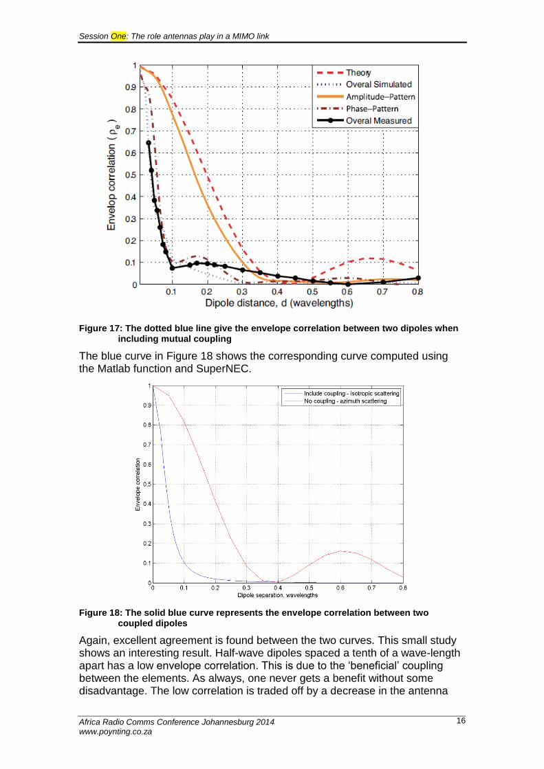
Figure 17: The dotted blue line give the envelope correlation between two dipoles when including mutual coupling
The blue curve in Figure 18 shows the corresponding curve computed using the Matlab function and SuperNEC.
Figure 18: The solid blue curve represents the envelope correlation between two coupled dipoles
Again, excellent agreement is found between the two curves. This small study shows an interesting result. Half-wave dipoles spaced a tenth of a wave-length apart has a low envelope correlation. This is due to the ‘beneficial’ coupling between the elements. As always, one never gets a benefit without some disadvantage. The low correlation is traded off by a decrease in the antenna
Session One: The role antennas play in a MIMO link
Africa Radio Comms Conference Johannesburg 2014 www.poynting.co.za
17
radiation efficiency as power transmitted from one antenna is absorbed by the other!
Illustrating the importance of low envelope correlation
It was mentioned in the introduction that Vaughan [ 1] derived a rule-of-thumb that states that good diversity operation (and hence good LTE performance) is possible when the envelope correlation of the patterns of an antenna is less than 0.5. In order to investigate this statement an experiment was conducted using an adjustable antenna and Vodacom’s LTE service.
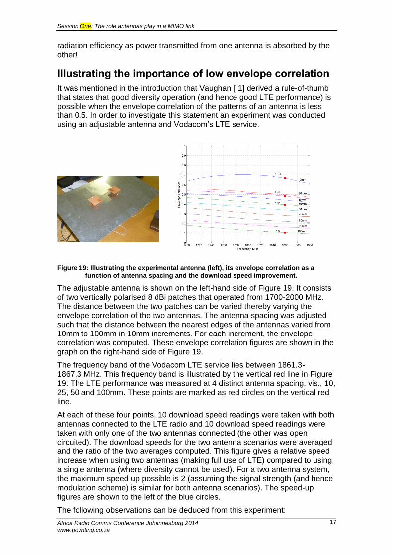
Figure 19: Illustrating the experimental antenna (left), its envelope correlation as a function of antenna spacing and the download speed improvement.
The adjustable antenna is shown on the left-hand side of Figure 19. It consists of two vertically polarised 8 dBi patches that operated from 1700-2000 MHz. The distance between the two patches can be varied thereby varying the envelope correlation of the two antennas. The antenna spacing was adjusted such that the distance between the nearest edges of the antennas varied from 10mm to 100mm in 10mm increments. For each increment, the envelope correlation was computed. These envelope correlation figures are shown in the graph on the right-hand side of Figure 19.
The frequency band of the Vodacom LTE service lies between 1861.3-1867.3 MHz. This frequency band is illustrated by the vertical red line in Figure 19. The LTE performance was measured at 4 distinct antenna spacing, vis., 10, 25, 50 and 100mm. These points are marked as red circles on the vertical red line.
At each of these four points, 10 download speed readings were taken with both antennas connected to the LTE radio and 10 download speed readings were taken with only one of the two antennas connected (the other was open circuited). The download speeds for the two antenna scenarios were averaged and the ratio of the two averages computed. This figure gives a relative speed increase when using two antennas (making full use of LTE) compared to using a single antenna (where diversity cannot be used). For a two antenna system, the maximum speed up possible is 2 (assuming the signal strength (and hence modulation scheme) is similar for both antenna scenarios). The speed-up figures are shown to the left of the blue circles.
The following observations can be deduced from this experiment:
Session One: The role antennas play in a MIMO link
Africa Radio Comms Conference Johannesburg 2014 www.poynting.co.za
18
Envelope correlation
Speed-up
Comment
0.67 1.04 The patterns of the two antennas are so well correlated that LTE hardly gives any improvement in performance
0.48 1.47 The patterns have some de-correlation and a 50% improvement in performance is recorded.
0.40 1.91 Here the LTE performance is close to the theoretical maximum performance that one can expect. This performance corresponds to an envelope correlation of 0.4 which agrees reasonably with rule-of-thumb given by Vaughan.
0.11 1.9 No additional improvement in LTE performance was achieved with an envelope correlation of 0.11.
Table 1: Summarising the results of the adjustable antenna experiment
Envelope correlation of the Poynting products
The envelope correlation function was computed for various cross-polarised MIMO antennas manufactured by Poynting; namely the, XPOL-A0001, XPOL-A0002 and XPOL-A0004 antennas. In addition, two LPDA-A0092 antennas were combined to form a dual polarised highly directional antenna. In each graph the ‘rule-of-thumb’ line for good diversity performance is depicted (if the correlation is below this line, then good diversity performance can be expected).
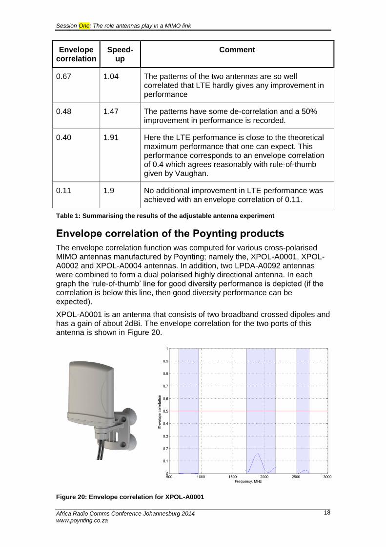
XPOL-A0001 is an antenna that consists of two broadband crossed dipoles and has a gain of about 2dBi. The envelope correlation for the two ports of this antenna is shown in Figure 20.
Figure 20: Envelope correlation for XPOL-A0001
Session One: The role antennas play in a MIMO link
Africa Radio Comms Conference Johannesburg 2014 www.poynting.co.za
19
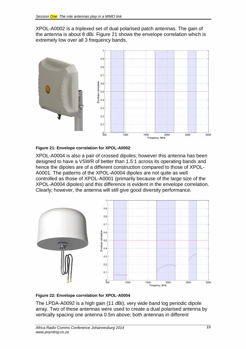
XPOL-A0002 is a triplexed set of dual polarised patch antennas. The gain of the antenna is about 8 dBi. Figure 21 shows the envelope correlation which is extremely low over all 3 frequency bands.
Figure 21: Envelope correlation for XPOL-A0002
XPOL-A0004 is also a pair of crossed dipoles; however this antenna has been designed to have a VSWR of better than 1.5:1 across its operating bands and hence the dipoles are of a different construction compared to those of XPOL-A0001. The patterns of the XPOL-A0004 dipoles are not quite as well controlled as those of XPOL-A0001 (primarily because of the large size of the XPOL-A0004 dipoles) and this difference is evident in the envelope correlation. Clearly; however, the antenna will still give good diversity performance.
Figure 22: Envelope correlation for XPOL-A0004
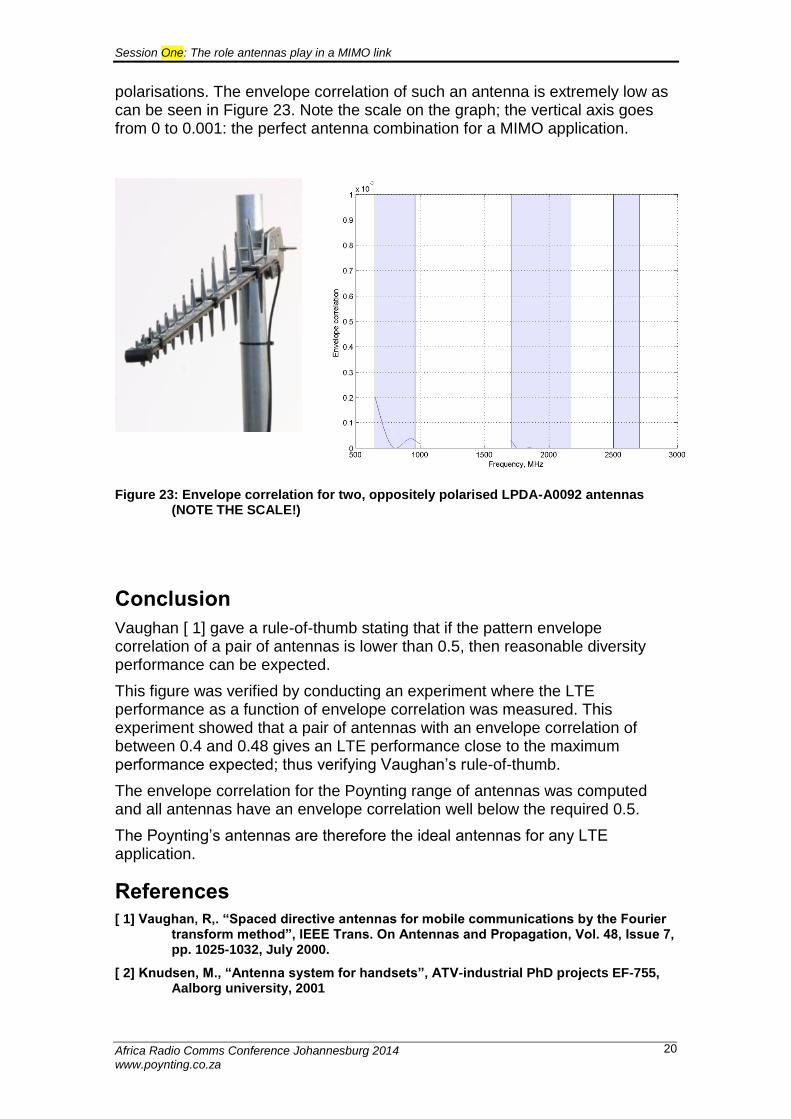
The LPDA-A0092 is a high gain (11 dBi), very wide band log periodic dipole array. Two of these antennas were used to create a dual polarised antenna by vertically spacing one antenna 0.5m above; both antennas in different
Session One: The role antennas play in a MIMO link
Africa Radio Comms Conference Johannesburg 2014 www.poynting.co.za
20
polarisations. The envelope correlation of such an antenna is extremely low as can be seen in Figure 23. Note the scale on the graph; the vertical axis goes from 0 to 0.001: the perfect antenna combination for a MIMO application.
Figure 23: Envelope correlation for two, oppositely polarised LPDA-A0092 antennas (NOTE THE SCALE!)
Conclusion
Vaughan [ 1] gave a rule-of-thumb stating that if the pattern envelope correlation of a pair of antennas is lower than 0.5, then reasonable diversity performance can be expected.
This figure was verified by conducting an experiment where the LTE performance as a function of envelope correlation was measured. This experiment showed that a pair of antennas with an envelope correlation of between 0.4 and 0.48 gives an LTE performance close to the maximum performance expected; thus verifying Vaughan’s rule-of-thumb.
The envelope correlation for the Poynting range of antennas was computed and all antennas have an envelope correlation well below the required 0.5.
The Poynting’s antennas are therefore the ideal antennas for any LTE application.
References
[ 1] Vaughan, R,. “Spaced directive antennas for mobile communications by the Fourier transform method”, IEEE Trans. On Antennas and Propagation, Vol. 48, Issue 7, pp. 1025-1032, July 2000.
[ 2] Knudsen, M., “Antenna system for handsets”, ATV-industrial PhD projects EF-755, Aalborg university, 2001
Session One: The role antennas play in a MIMO link
Africa Radio Comms Conference Johannesburg 2014 www.poynting.co.za
21
[ 3] Khaleghi, A., “Diversity techniques with parallel dipole antennas: radiation pattern analysis”, Progress in electromagnetic research, PIER 64, 23-42, 2006
[ 4] Clarke, R., “A statistical theory of mobile radio reception”, Bell Syst. Tech. J., Vol., 47, pp., 957-1000, 1969