Embed Size (px)
Citation preview
Orthogonal MIMO Antennas for Compact Cellular
Handsets
M. Bank, K. Slupenko, M Haridim, V. Tsingouz
Abstract- we propose a novel compact MIMO antenna system
for small handsets, based on two different types of antennas –a
small loop and the MB antenna. The MB antenna is an enhanced
dipole antenna, which can be implemented as internal antenna in a
compact cellular handset. Similar to conventional dipole, MB is an
electrical antenna; and the small loop is a magnetic antenna. It is
shown that using these antenna one can create a compact MIMO
system, with small mutual coupling between the antennas, even
when the distance between them is smaller than λ/3. We also
present a new method for increasing the radiation efficiency of
small loop antennas at frequencies higher than 470MHz.
Simulations results show that the mutual coupling between MB
and small loop antennas is low.
Keywords—MIMO, LTE, cellular handset, MB antenna, small
loop antenna.
I. INTRODUCTION
HIS cellular phone systems have evolved rapidly over
the past several decades, during which the size and
weight of the phone handsets have continuously
decreased[1] .Next generation wireless devices must
incorporate the MIMO technology with multiple antennas
implemented in a small area .
Multiple Input and Multiple Output (MIMO) technology is
the most promising, if not the last frontier, in the evolution
of wireless broadband access networks. In MIMO systems,
signals from multiple antennas are combined to mitigate
multipath effects, to improve channel capacity, to improve
network coverage, and to increase link reliability [2]. In
order to explore the diversity and multiplexing gains
offered by the MIMO technology, the antennas spacing
must be typically half wavelength [2]
LTE is the next generation cellular phone technology that
aims to achieve a high peak data rate, low latency, and high
radio efficiency in addition to low cost and sufficiently high
mobility characteristics [1, 2]. One important characteristic
of the LTE standard is the requirement for implementing
MIMO architecture.
Manuscript received May 18, 2012M. Bank is with Jerusalem college
ofTechnology, E-Mail: [email protected] ,
K. Slupenko, M Haridim, V. Tsingouz are with HIT-Holon Institute of
Technology, E-Mail; [email protected]
The LTE standard refers to various frequency bands. In this
paper we consider the lowest band of 698-798MHz. At
these low frequencies, implementing multiple antennas in a
handheld device poses significant challenge in terms of
high antenna radiation efficiency,high isolation, and low
mutual coupling between the antennas. Mutual coupling
between the antennas is determined by separation between
the antennas, measured in terms of fractions of the
wavelength used. Actually, it is attributed to the constraints
on the dimensions of the handset (typically around
50x100mm) and the existence of the PCB which acts as a
ground plane.
This paper presents a study of an innovative MIMO antenna
system for compact mobile handsets, in which the distance
between the antennas is less than λ/3 and the operating
frequency is about 730MHz. In order to reduce the mutual
coupling between the antennas we propose to use antennas
of different types – electrical and magnetic, where the
former is MB antenna [3], and the latter is a small loop
antenna.
MB antenna is an enhanced dipole whose radiating element
is the PCB (Printed Circuit Board) of the handset. In
contrast to the conventional dipole and/or monopole the
MB antenna can be implemented as an internal antenna in a
compact cellular handset [3].
Small loops form another antenna type. The frequency
range of this antenna is generally 285 to 470MHz [4]. Due
to its extremely low radiation efficiency (only 1-20%),
small loops are used predominantly as receiving antennas,
where signal-to-noise ratio, and not antenna efficiency, is
the most important factor [5].
Besides the proposed MIMO antenna system, we present a
new method for increasing the low radiation efficiency of
loop antennas at frequencies beyond 470MHz.
Simulation results show that it is possible to obtain low
mutual coupling between the antennas of the investigated
MIMO system, even when the distance between them is
much smaller than λ/3.
II. THE MB ANTENNA
The MB antenna (MBA) is a modified version of a
linear antenna that allows for the radiating element
T
INTERNATIONAL JOURNAL OF COMMUNICATIONS Issue 3, Volume 6, 2012
89
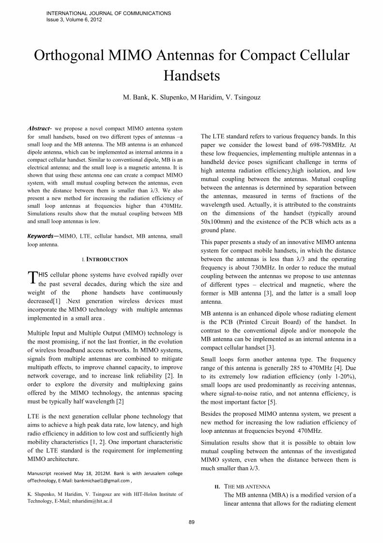
to be implemented by the handset's PCB which
acts as a ground plane at cellular frequencies. Fig.
1 illustrates the directions of the currents when the
radiating trace of a monopole antenna is
implemented in parallel to a ground plane. As seen
in this Figure, the currents in the conducting trace
and in the ground plane are anti-parallel, resulting
in very low radiation efficiency because of the
destructive superposition of the fields produced by
these currents.
Fig. 1Monopole in parallel to ground plane.
The main idea behind the MBA is to introduce a phase shift
of 180˚ in the feed path of the radiating trace (relative to the
ground) so that the two currents become in-phase and flow
in the same direction. In this way, the fields emanating
from the trace and the ground plane will be in-phase and
hence add up, resulting in high radiation efficiency similar
to that of conventional monopole antennas. The phase
shifter can be implemented in various ways, provided the
following two requirements are fulfilled: 1) it must be
realized in a non-radiating shape, 2) its electric length
(corresponding to the center frequency) must be designed
such that the currents in the radiating element and the
ground plane are in-phase and flow in the same direction.
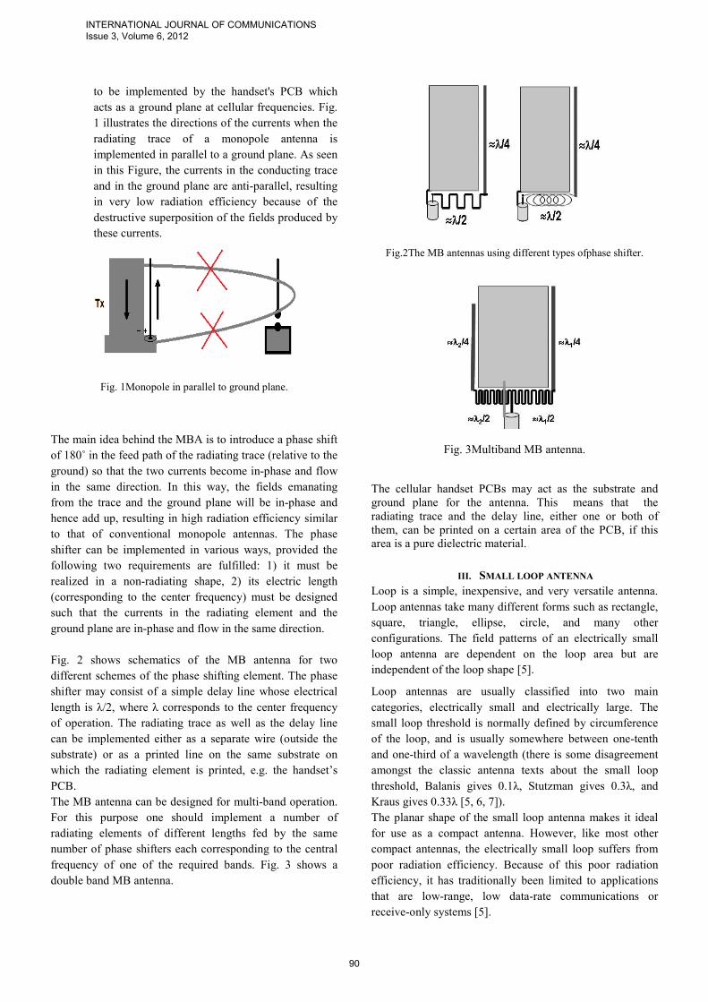
Fig. 2 shows schematics of the MB antenna for two
different schemes of the phase shifting element. The phase
shifter may consist of a simple delay line whose electrical
length is λ/2, where λ corresponds to the center frequency
of operation. The radiating trace as well as the delay line
can be implemented either as a separate wire (outside the
substrate) or as a printed line on the same substrate on
which the radiating element is printed, e.g. the handset’s
PCB.
The MB antenna can be designed for multi-band operation.
For this purpose one should implement a number of
radiating elements of different lengths fed by the same
number of phase shifters each corresponding to the central
frequency of one of the required bands. Fig. 3 shows a
double band MB antenna.
Fig.2The MB antennas using different types ofphase shifter.
Fig. 3Multiband MB antenna.
The cellular handset PCBs may act as the substrate and
ground plane for the antenna. This means that the
radiating trace and the delay line, either one or both of
them, can be printed on a certain area of the PCB, if this
area is a pure dielectric material.
III. SMALL LOOP ANTENNA
Loop is a simple, inexpensive, and very versatile antenna.
Loop antennas take many different forms such as rectangle,
square, triangle, ellipse, circle, and many other
configurations. The field patterns of an electrically small
loop antenna are dependent on the loop area but are
independent of the loop shape [5].
Loop antennas are usually classified into two main
categories, electrically small and electrically large. The
small loop threshold is normally defined by circumference
of the loop, and is usually somewhere between one-tenth
and one-third of a wavelength (there is some disagreement
amongst the classic antenna texts about the small loop
threshold, Balanis gives 0.1λ, Stutzman gives 0.3λ, and
Kraus gives 0.33λ [5, 6, 7]).
The planar shape of the small loop antenna makes it ideal
for use as a compact antenna. However, like most other
compact antennas, the electrically small loop suffers from
poor radiation efficiency. Because of this poor radiation
efficiency, it has traditionally been limited to applications
that are low-range, low data-rate communications or
receive-only systems [5].
INTERNATIONAL JOURNAL OF COMMUNICATIONS Issue 3, Volume 6, 2012
90
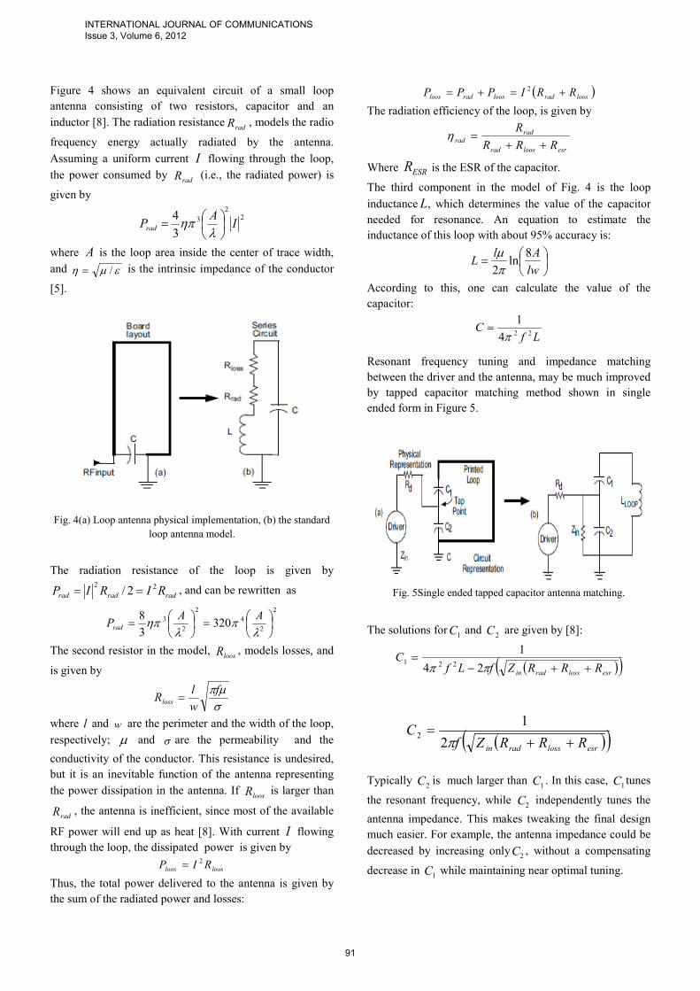
Figure 4 shows an equivalent circuit of a small loop
antenna consisting of two resistors, capacitor and an
inductor [8]. The radiation resistanceradR , models the radio
frequency energy actually radiated by the antenna.
Assuming a uniform current I flowing through the loop,
the power consumed by radR (i.e., the radiated power) is
given by
22
3
3
4I
APrad
=λ
ηπ
where A is the loop area inside the center of trace width,
and εµη /= is the intrinsic impedance of the conductor
[5].
Fig. 4(a) Loop antenna physical implementation, (b) the standard
loop antenna model.
The radiation resistance of the loop is given by
radradrad RIRIP 222/ == , and can be rewritten as
2
2
4
2
2
3 3203
8
=
=λ
πλ
ηπAA
Prad
The second resistor in the model, loosR , models losses, and
is given by
σµπf
w
lRloss =
where l and w are the perimeter and the width of the loop,
respectively; µ and σ are the permeability and the
conductivity of the conductor. This resistance is undesired,
but it is an inevitable function of the antenna representing
the power dissipation in the antenna. If loosR is larger than
radR , the antenna is inefficient, since most of the available
RF power will end up as heat [8]. With current I flowing
through the loop, the dissipated power is given by
loosloos RIP 2=
Thus, the total power delivered to the antenna is given by
the sum of the radiated power and losses:
( )loosradloosradloos RRIPPP +=+= 2
The radiation efficiency of the loop, is given by
esrloosrad
rad
radRRR
R
++=η
Where ESRR is the ESR of the capacitor.
The third component in the model of Fig. 4 is the loop
inductanceL, which determines the value of the capacitor
needed for resonance. An equation to estimate the
inductance of this loop with about 95% accuracy is:
=lw
AlL
8ln
2πµ
According to this, one can calculate the value of the
capacitor:
LfC
224
1
π=
Resonant frequency tuning and impedance matching
between the driver and the antenna, may be much improved
by tapped capacitor matching method shown in single
ended form in Figure 5.
Fig. 5Single ended tapped capacitor antenna matching.
The solutions for1C and
2C are given by [8]:
( )( )esrlossradin RRRZfLfC
++−=
ππ 24
1221
( )( )esrlossradin RRRZfC
++=
π2
12
Typically 2C is much larger than
1C . In this case, 1C tunes
the resonant frequency, while 2C independently tunes the
antenna impedance. This makes tweaking the final design
much easier. For example, the antenna impedance could be
decreased by increasing only2C , without a compensating
decrease in 1C while maintaining near optimal tuning.
INTERNATIONAL JOURNAL OF COMMUNICATIONS Issue 3, Volume 6, 2012
91
IV. SOLUTION FOR LOW RADIATION EFFICIENCY OF
THE SMALL LOOP ANTENNA
According to the formula of 1C one can see that increasing
the antenna resonant frequency cause lowering of the
capacitor. In practice, it is difficult to realize an antenna
with capacitance smaller than 2-3pF, due the parasitic
capacitance, which begins to affect the performance of the
antenna. The capacitance can be increased by reducing the
antenna inductance, but in this case, in the formula of L , it
can be seen that this directly affects the antenna's effective
area. As a result, the antenna will have a very poor radiation
efficiency, and cannot be used as a transmit antenna.
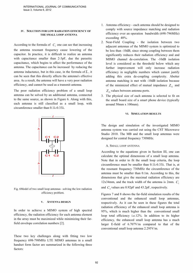
The poor radiation efficiency problem of a small loop
antenna can be solved by an additional antenna, connected
to the same source, as shown in Figure 6. Along with this,
each antenna is still classified as a small loop, with
circumference smaller than 0.1λ-0.33λ.
Fig. 6Model of two small loop antennas –solving the low radiation
efficiency problem.
V. ANTENNA DESIGN
In order to achieve a MIMO system of high spectral
efficiency, the radiation efficiency for each antenna element
in the array must be maximized while minimizing their far-
field envelope correlation numbers [2].
These two key challenges along with fitting two low
frequency 698-798MHz LTE MIMO antennas in a small
handset form factor are summarized in the following three
factors:
1. Antenna efficiency - each antenna should be designed to
comply with source impedance matching and radiation
efficiency over an operation bandwidth (698-796MHz)
exceeding 40%.
2. Near-Field Coupling - the isolation between two
adjacent antennas of the MIMO system is optimized to
be less than -10dB, since strong coupling between them
significantly reduces their radiation efficiency and and
MIMO channel de-correlation. The -10dB isolation
level is considered as the threshold below which any
further improvement will only increase radiation
efficiency in negligible numbers which cannot justify
adding this extra de-coupling complexity. Abetter
antenna matching is met with -10dB isolation because
of the minimized effect of mutual impedance 12Z and
21Z values between antenna ports.
3. The physical size of each antenna is selected to fit on
the small board size of a smart phone device (typically
around 50mm x 100mm).
VI. SIMULATION RESULTS
The design and simulation of the investigated MIMO
antenna system was carried out using the CST Microwave
Studio 2010. The MB and the small loop antennas were
designed for central frequency 730MHz.
A. SMALL LOOP ANTENNA
According to the equations given in Section III, one can
calculate the optimal dimensions of a small loop antenna.
Note that in order to fit the small loop criteria, the loop
circumference must be smaller than 0.1λ-0.33λ. That is, at
the resonant frequency 730MHz the circumference of the
antenna must be smaller than 0.1m. According to this, the
dimensions that give the maximal radiation efficiency are
12x34mm, and the track width of the antenna is 2mm. 1C
and 2C values are 0.92pF and 43.2pF, respectively.
Figures 7 and 8 shows the far-field simulation results of the
conventional and the enhanced small loop antennas,
respectively. As it can be seen in these figures the total
radiation efficiency of the enhanced small loop antenna is
95%, which is much higher than the conventional small
loop total efficiency i.e.12%. In addition to its higher
efficiency, the enhanced small loop antenna has a much
larger E-field of 6.707V/m compared to that of the
conventional small loop antenna 2.295V/m.
INTERNATIONAL JOURNAL OF COMMUNICATIONS Issue 3, Volume 6, 2012
92

Fig. 7Conventional small loop antenna.
Fig. 8 – Enhanced small loop antenna.
Figure 9 shows the simulation results of the S11
characteristics of the enhanced small loop antenna. These
results show a S11 of -21.58dB at the resonance frequency
(730MHz).
Fig. 9 – S11 simulation results of the enhanced small loop
antenna.
In order to simulate the handset's PCB impact on the
antenna performance, a dielectric substrate was attached to
the enhanced small loop antenna, as shown in Figure 10.
Table 1 shows that there is no performance degradation
caused by the adjacent dielectric substrate.
Fig. 10 Enhanced small loop antenna with adjacent dielectric
substrate.
Table 1-The impactof PCB presence on the small loop antenna
performance
.Antenna type S11
[dB]
Rad.
Effic.
Tot.
Effic.
Emax
[V/m]
Enhanced small
loop
-
21.58 0.9656 0.9589 6.707
Enhanced small
loop with adjacent
dielectric substrate
-
20.11 0.9891 0.9795 6.788
From simulation results shown in Figures 11, 12 and Table
2 it can be seen that it is possible to create a compact
multiband small loop antenna system, which operates as a
transmitter at frequencies higher than 470MHz. The
dimensions of the four-antenna array system are
2x57x104mm, so it can be implemented in compact
systems, such as a mobile handset or smart phone. In
addition, in order to obtain an omnidirectional radiation
pattern, this configuration of small loop antennas allows a
90˚ rotation of the antenna relative to another antenna.
Fig. 11 – System of 4 small loop antennas.
INTERNATIONAL JOURNAL OF COMMUNICATIONS Issue 3, Volume 6, 2012
93
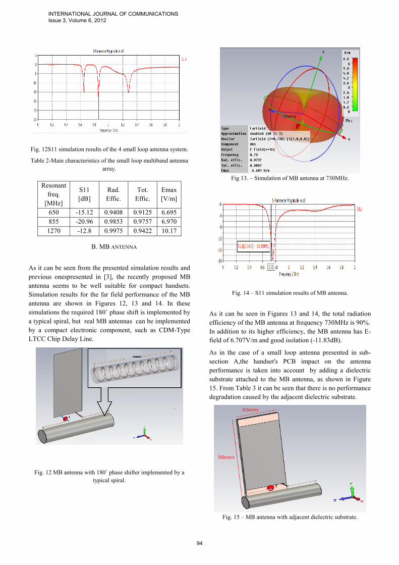
Fig. 12S11 simulation results of the 4 small loop antenna system.
Table 2-Main characteristics of the small loop multiband antenna
array.
Resonant
freq.
[MHz]
S11
[dB]
Rad.
Effic.
Tot.
Effic.
Emax
[V/m]
650 -15.12 0.9408 0.9125 6.695
855 -20.96 0.9853 0.9757 6.970
1270 -12.8 0.9975 0.9422 10.17
B. MB ANTENNA
As it can be seen from the presented simulation results and
previous onespresented in [3], the recently proposed MB
antenna seems to be well suitable for compact handsets.
Simulation results for the far field performance of the MB
antenna are shown in Figures 12, 13 and 14. In these
simulations the required 180˚ phase shift is implemented by
a typical spiral, but real MB antennas can be implemented
by a compact electronic component, such as CDM-Type
LTCC Chip Delay Line.
Fig. 12 MB antenna with 180˚ phase shifter implemented by a
typical spiral.
Fig 13. – Simulation of MB antenna at 730MHz.
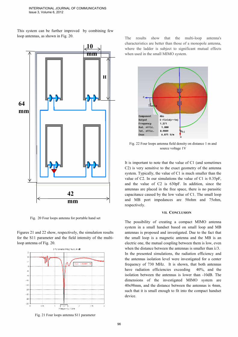
Fig. 14 – S11 simulation results of MB antenna.
As it can be seen in Figures 13 and 14, the total radiation
efficiency of the MB antenna at frequency 730MHz is 90%.
In addition to its higher efficiency, the MB antenna has E-
field of 6.707V/m and good isolation (-11.83dB).
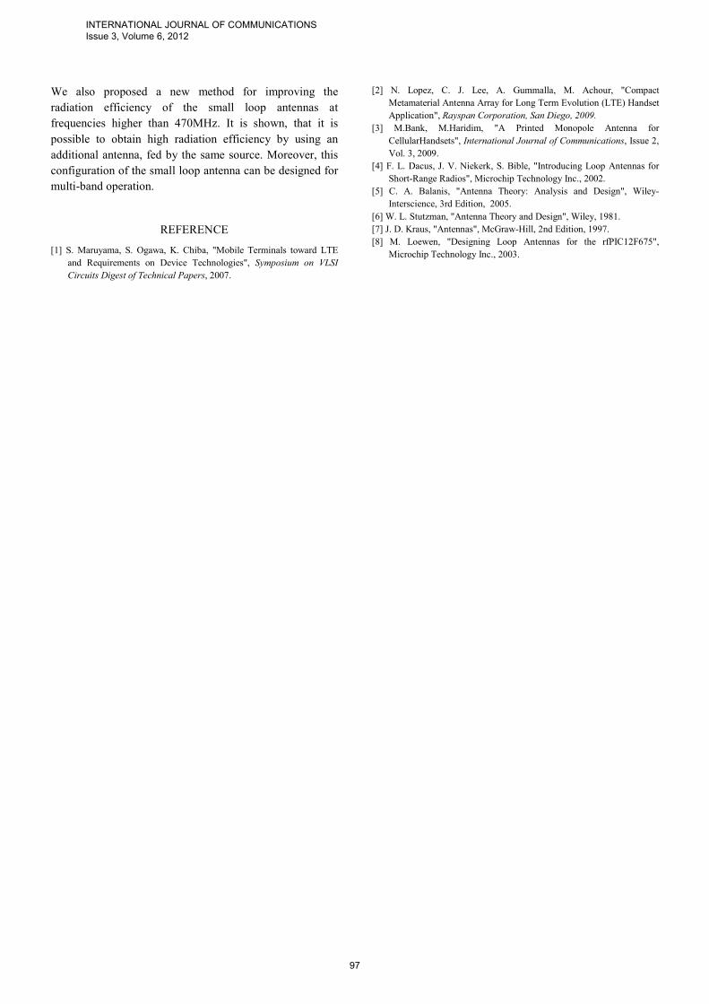
As in the case of a small loop antenna presented in sub-
section A,the handset's PCB impact on the antenna
performance is taken into account by adding a dielectric
substrate attached to the MB antenna, as shown in Figure
15. From Table 3 it can be seen that there is no performance
degradation caused by the adjacent dielectric substrate.
Fig. 15 – MB antenna with adjacent dielectric substrate.
INTERNATIONAL JOURNAL OF COMMUNICATIONS Issue 3, Volume 6, 2012
94
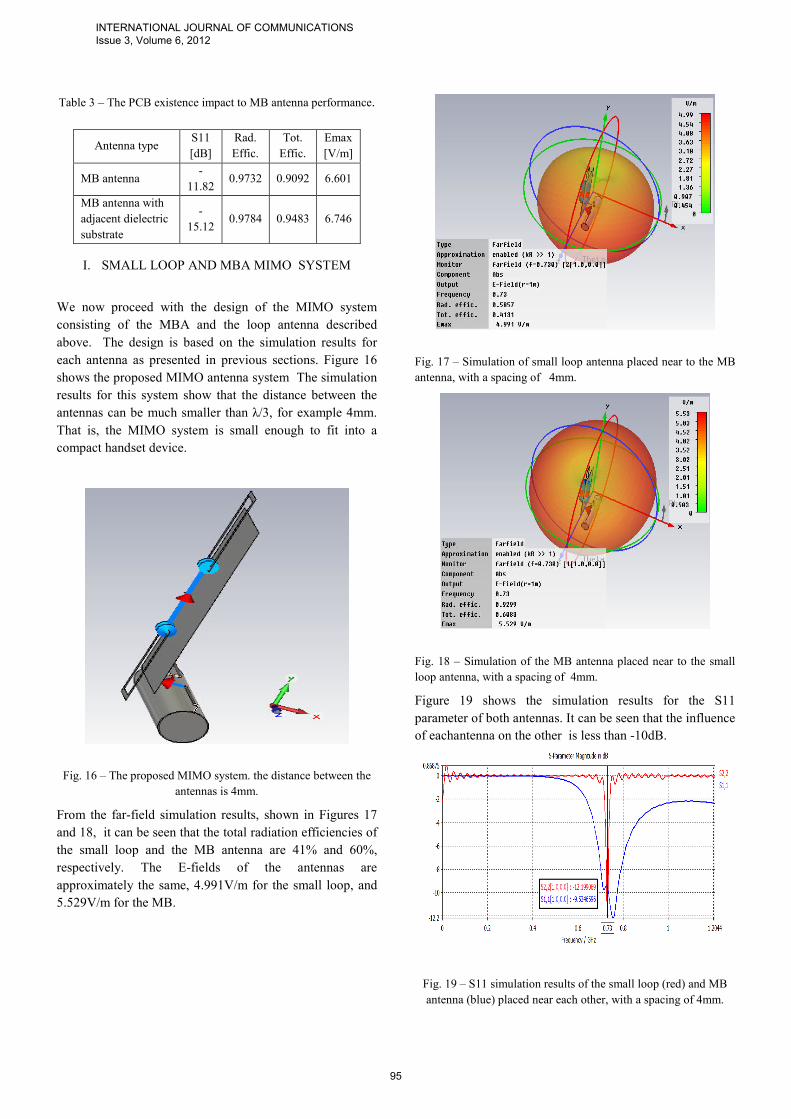
Table 3 – The PCB existence impact to MB antenna performance.
Antenna type S11
[dB]
Rad.
Effic.
Tot.
Effic.
Emax
[V/m]
MB antenna -
11.82 0.9732 0.9092 6.601
MB antenna with
adjacent dielectric
substrate
-
15.12 0.9784 0.9483 6.746
I. SMALL LOOP AND MBA MIMO SYSTEM
We now proceed with the design of the MIMO system
consisting of the MBA and the loop antenna described
above. The design is based on the simulation results for
each antenna as presented in previous sections. Figure 16
shows the proposed MIMO antenna system The simulation
results for this system show that the distance between the
antennas can be much smaller than λ/3, for example 4mm.
That is, the MIMO system is small enough to fit into a
compact handset device.
Fig. 16 – The proposed MIMO system. the distance between the
antennas is 4mm.
From the far-field simulation results, shown in Figures 17
and 18, it can be seen that the total radiation efficiencies of
the small loop and the MB antenna are 41% and 60%,
respectively. The E-fields of the antennas are
approximately the same, 4.991V/m for the small loop, and
5.529V/m for the MB.
Fig. 17 – Simulation of small loop antenna placed near to the MB
antenna, with a spacing of 4mm.
Fig. 18 – Simulation of the MB antenna placed near to the small
loop antenna, with a spacing of 4mm.
Figure 19 shows the simulation results for the S11
parameter of both antennas. It can be seen that the influence
of eachantenna on the other is less than -10dB.
Fig. 19 – S11 simulation results of the small loop (red) and MB
antenna (blue) placed near each other, with a spacing of 4mm.
INTERNATIONAL JOURNAL OF COMMUNICATIONS Issue 3, Volume 6, 2012
95
This system can be further improved by combining few
loop antennas, as shown in Fig. 20.
Fig. 20 Four loops antenna for portable hand set
Figures 21 and 22 show, respectively, the simulation results
for the S11 parameter and the field intensity of the multi-
loop antenna of Fig. 20.
Fig. 21 Four loops antenna S11 parameter
The results show that the multi-loop antenna's
characteristics are better than those of a monopole antenna,
where the ladder is subject to significant mutual effects
when used in the small MIMO system.
Fig. 22 Four loops antenna field density on distance 1 m and
source voltage 1V
It is important to note that the value of C1 (and sometimes
C2) is very sensitive to the exact geometry of the antenna
system. Typically, the value of C1 is much smaller than the
value of C2. In our simulations the value of C1 is 0.35pF,
and the value of C2 is 630pF. In addition, since the
antennas are placed in the free space, there is no parasitic
capacitance caused by the low value of C1. The small loop
and MB port impedances are 50ohm and 75ohm,
respectively.
VII. CONCLUSION
The possibility of creating a compact MIMO antenna
system in a small handset based on small loop and MB
antennas is proposed and investigated. Due to the fact that
the small loop is a magnetic antenna and the MB is an
electric one, the mutual coupling between them is low, even
when the distance between the antennas is smaller than λ/3.
In the presented simulations, the radiation efficiency and
the antennas isolation level were investigated for a center
frequency of 730 MHz. It is shown, that both antennas
have radiation efficiencies exceeding 40%, and the
isolation between the antennas is lower than -10dB. The
dimensions of the investigated MIMO system are
40x98mm, and the distance between the antennas is 4mm,
such that it is small enough to fit into the compact handset
device.
H
10
mm
64
mm
42
mm
INTERNATIONAL JOURNAL OF COMMUNICATIONS Issue 3, Volume 6, 2012
96
We also proposed a new method for improving the
radiation efficiency of the small loop antennas at
frequencies higher than 470MHz. It is shown, that it is
possible to obtain high radiation efficiency by using an
additional antenna, fed by the same source. Moreover, this
configuration of the small loop antenna can be designed for
multi-band operation.
REFERENCE
[1] S. Maruyama, S. Ogawa, K. Chiba, "Mobile Terminals toward LTE
and Requirements on Device Technologies", Symposium on VLSI
Circuits Digest of Technical Papers, 2007.
[2] N. Lopez, C. J. Lee, A. Gummalla, M. Achour, "Compact
Metamaterial Antenna Array for Long Term Evolution (LTE) Handset
Application", Rayspan Corporation, San Diego, 2009.
[3] M.Bank, M.Haridim, "A Printed Monopole Antenna for
CellularHandsets", International Journal of Communications, Issue 2,
Vol. 3, 2009.
[4] F. L. Dacus, J. V. Niekerk, S. Bible, "Introducing Loop Antennas for
Short-Range Radios", Microchip Technology Inc., 2002.
[5] C. A. Balanis, "Antenna Theory: Analysis and Design", Wiley-
Interscience, 3rd Edition, 2005.
[6] W. L. Stutzman, "Antenna Theory and Design", Wiley, 1981.
[7] J. D. Kraus, "Antennas", McGraw-Hill, 2nd Edition, 1997.
[8] M. Loewen, "Designing Loop Antennas for the rfPIC12F675",
Microchip Technology Inc., 2003.
INTERNATIONAL JOURNAL OF COMMUNICATIONS Issue 3, Volume 6, 2012
97