Embed Size (px)
Citation preview
ArIns
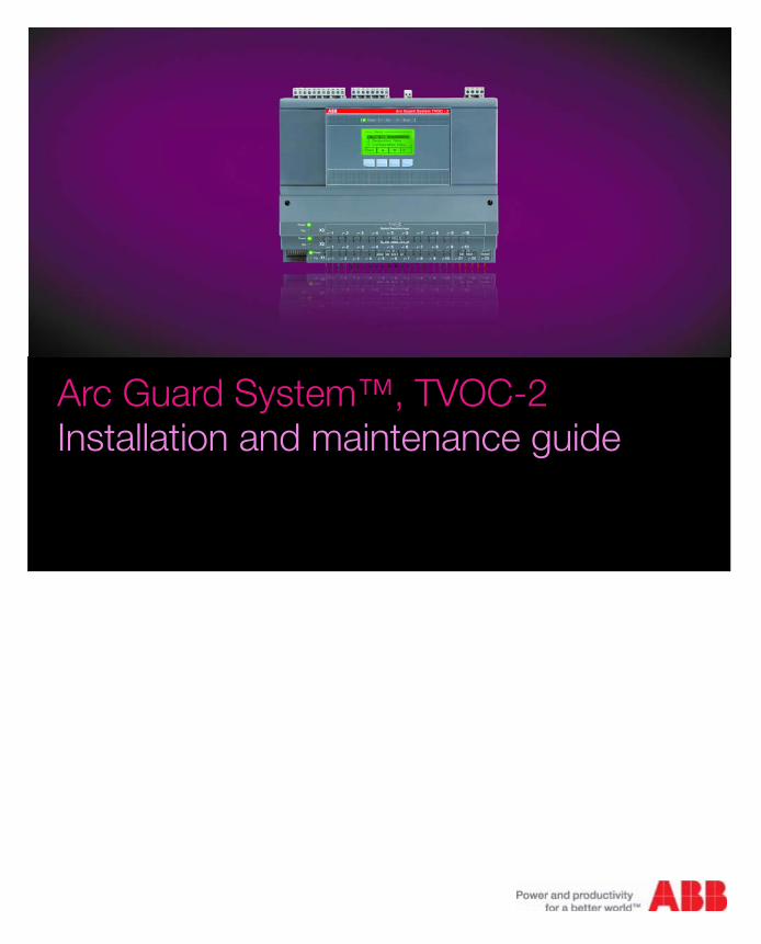
c Guard System™, TVOC-2tallation and maintenance guide

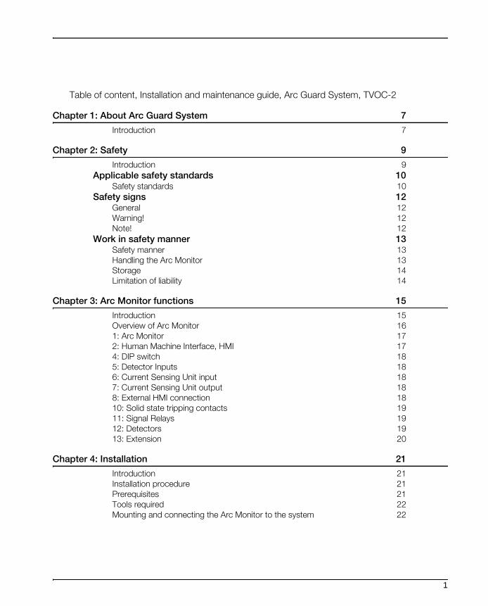
Table of content, Installation and maintenance guide, Arc Guard System, TVOC-2
Chapter 1: About Arc Guard System 7
Introduction 7
Chapter 2: Safety 9
Introduction 9
Applicable safety standards 10Safety standards 10
Safety signs 12General 12Warning! 12Note! 12
Work in safety manner 13Safety manner 13Handling the Arc Monitor 13Storage 14Limitation of liability 14
Chapter 3: Arc Monitor functions 15
Introduction 15Overview of Arc Monitor 161: Arc Monitor 172: Human Machine Interface, HMI 174: DIP switch 185: Detector Inputs 186: Current Sensing Unit input 187: Current Sensing Unit output 188: External HMI connection 1810: Solid state tripping contacts 1911: Signal Relays 1912: Detectors 1913: Extension 20
Chapter 4: Installation 21
Introduction 21Installation procedure 21Prerequisites 21Tools required 22Mounting and connecting the Arc Monitor to the system 22
1

Getting started 23Introduction 23Receiving and checking 23List of contents 23Intermediate storage 23
Mounting 24Introduction 24Placing Arc Monitor 24Mounting Arc Monitor 24Mounting on wall 25Mounting on a DIN rail 25Mounting the HMI 26Mounting the HMI on door 26Mounting the Optical detector 27Example 1, positioning Optical detector in a switch gear 28Example 2, Mounting Optical detector in an apertures cubicle 29Example 3, Mounting in a cir- cuit breaker cubicle 30Connecting optical detectors 32Connecting extension module (option) 33Connecting CSU cable 34
Electrical connections 35Introduction 35Connecting HMI 35Connecting optical detector 35Connecting extension module (option) 35Connecting Current Sensing Unit (option) 35Electrical connections 36Connecting the Arc Monitor 37
Configurations 39Introduction 39DIP switches 39Breaker trip 40DIP switches 3 and 4 to position 0 40DIP switch 3 in position 0, DIP switch 4 to postiotion ON 40DIP switch 3 to position ON and DIP switch 4 to position 0. 41DIP switches 1, 2, 3 and 4 to position ON 41Manual/Auto reset configuration 42Current Sensing Unit(option) 43No CSU connected 43One (1) CSU connected 44Two (2) CSU connected 44Power on to the Arc Monitor 45Checking power on Arc Monitor 45Add/Remove module from the Arc Monitor or changing configuration 46
2

Settings 47Introduction 47Start-Up Sequence 47Step 1: Setting menu language 47Available languages 48Step 2: Setting time 48Step 3: Confirming connected modules 48Step 4: Checking DIP Switches 49Step 5: Final confirmation 50
Controlling 51Introduction 51Testing the installation 51
Chapter 5: Maintenance 53
Introduction 53Maintenance 53
Chapter 6: Trouble shooting 55
Introduction 55Requirements 55Troubleshooting 55Handling Error log 55Diagnostics 55Error event 55Error Log 56Error indication 56Attending errors 56Viewing error log 57List of error codes 57
ABB support 60Introduction 60Contact information 60Providing information 60
3
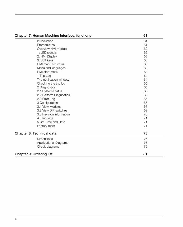
Chapter 7: Human Machine Interface, functions 61
Introduction 61Prerequisites 61Overview HMI module 621: LED signals 622: HMI Display 633: Soft keys 63HMI menu structure 63Menu and languages 63HMI start menu 631 Trip Log 64Trip notification window 64Checking the trip log 652 Diagnostics 652.1 System Status 662.2 Perform Diagnostics 662.3 Error Log 673 Configuration 673.1 View Modules 683.2 View DIP switches 693.3 Revision information 704 Language 715 Set Time and Date 71Factory reset 71
Chapter 8: Technical data 73
Dimensions 76Applications, Diagrams 76Circuit diagrams 79
Chapter 9: Ordering list 81
4
Installation and maintenance guide, Arc Guard System, TVOC-2
This is the installation and maintenance guide for Arc Guard System,
TVOC-2.
Documentnumber: 1SFC1700011M0201
Edition: 01
Revision: 01
Issue date: 2010-05
Data subject to change without notice.
We reserve all rights to this document, even in the event that a patent is
issued and a different commercial proprietary right is registered. Improper
use, in particular reproduction and dissemination to third parties, is not per-
mitted.
This document has been carefully checked. If the user neverthelass detects
any errors, he or she is kindly asked to notify us as soon as possible.
The data contained in this manual is intended solely for the product descrip-
tion and is not to be deemed to be a statement of guaranteed properties. In
the interests of our customers, we constantly seek to ensure that our prod-
ucts are developed to the latest technological standards.
As a result, there may be some differences between the Arc Monitor and the
information in this manual.
Author’s adress
ABB AB, Cewe-Control
S-721 61 Västerås
Sweden
Tel:+ 46 (0) 21 32 07 00
Fax: + 46 (0) 21 12 60 01
http://wwww.abb.com/lowvoltage
© ABB AB, Division Low Voltage Products, Cewe control
5

6

About Arc Guard System
Chapter 1: About Arc Guard System
Introduction Arc Guard System™ TVOC-2 quickly detects an arc and trips the incoming
circuit-breaker. Using light as the main condition, Arc Guard System™ trips
instantaneously. Thanks to this key functional advantage, it overrides all other
protections and delays, which is crucial when reaction times need to be
mesured in milliseconds. The Arc Guard System consists of the Arc Monitor
and optical sensor used for detection of the arc. For some special applica-
tions, an additional current sensing unit can be added. This a measure to
prevent unintentional tripping from strong light, for example, the sun.
The basic function acts in three phases:
• Detection is light passing through an optical sensor.
• Recognition is the Arc Monitor determining the intensity of light.
• Action is the trip contact closing.
7

About Arc Guard System
8
Safety
Chapter 2: Safety
Introduction This chapter describes the safety principles and procedures to be used when
working with the Arc Guard System or the Arc Monitor.
It does not cover how to design for safety nor how to install safety related
equipment.
The chapter first presents applicable safety standards.
Finally the chapter finishes with information about how to work in safety man-
ner.
9
Safety
Applicable safety standards
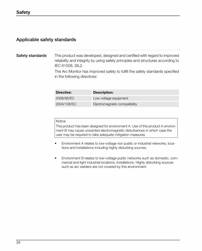
Safety standards This product was developed, designed and certified with regard to improved
reliability and integrity by using safety principles and structures according to
IEC 61508, SIL2.
The Arc Monitor has improved safety to fulfill the safety standards specified
in the following directives:
• Environment A relates to low-voltage non public or industrial networks, loca-tions and installations including highly disturbing sources.
• Environment B relates to low-voltage public networks such as domestic, com-mercial and light industrial locations, installations. Highly disturbing sources such as arc welders are not covered by this environment.
Directive: Description:
2006/95/EC Low voltage equipment
2004/108/EC Electromagnetic compatibility
Notice
This product has been designed for environment A. Use of this product in environ-ment B may cause unwanted electromagnetic disturbances in which case the user may be required to take adequate mitigation measures.
10
Safety
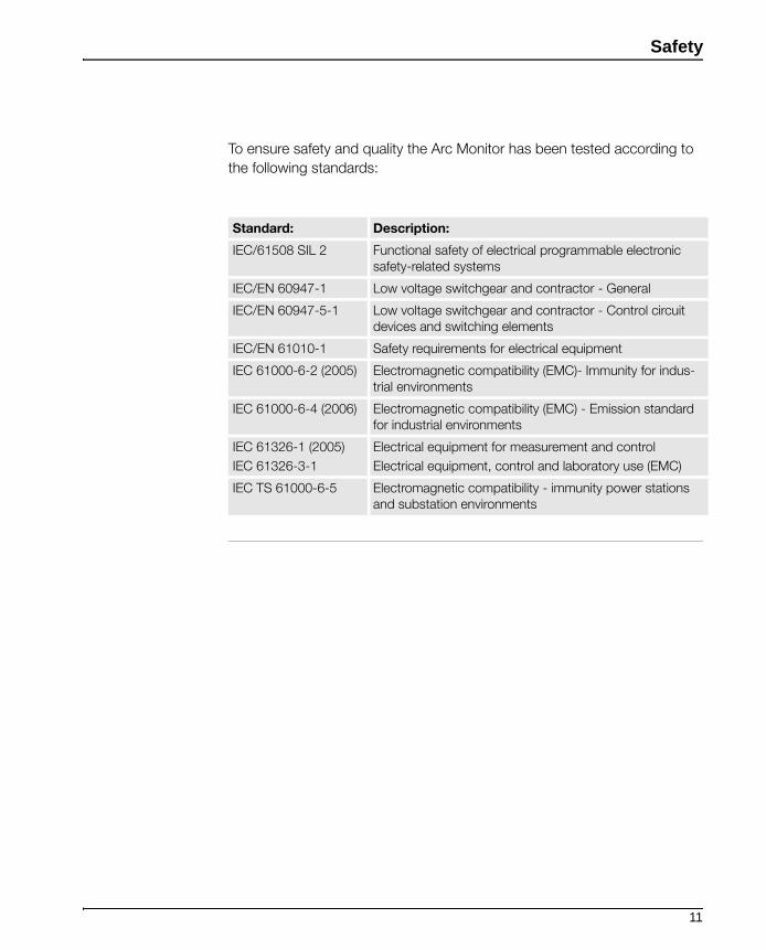
To ensure safety and quality the Arc Monitor has been tested according to
the following standards:
Standard: Description:
IEC/61508 SIL 2 Functional safety of electrical programmable electronic safety-related systems
IEC/EN 60947-1 Low voltage switchgear and contractor - General
IEC/EN 60947-5-1 Low voltage switchgear and contractor - Control circuit devices and switching elements
IEC/EN 61010-1 Safety requirements for electrical equipment
IEC 61000-6-2 (2005) Electromagnetic compatibility (EMC)- Immunity for indus-trial environments
IEC 61000-6-4 (2006) Electromagnetic compatibility (EMC) - Emission standard for industrial environments
IEC 61326-1 (2005)
IEC 61326-3-1
Electrical equipment for measurement and control
Electrical equipment, control and laboratory use (EMC)
IEC TS 61000-6-5 Electromagnetic compatibility - immunity power stationsand substation environments
11

Safety
Safety signs
General This section specifies all dangers that may arise from performing the work
detailed in the manual.
Warning! The Warning symbol warns that an accident will or may occur if the instruc-
tions are not followed.
Warning!
Make sure that the supply voltage has been switched off before connecting!
Working with high voltage is potentially lethal. Persons subjected to high volt-
age may suffer cardiac arrest, burn injuries, or other severe injuries. To avoid
these hazards, do not proceed working before removing the power to the Arc
Guard System.
Arc Guard System and Arc Monitor are designed to protect people and
installation equipment. Install your system components and Arc Monitor
before supplying power.
DIP switches are used to activate Current Sensing Unit (CSU), auto reset and
assigning trip contacts. Changing DIP switch can cause consequences with
the Arc Guard System.
Make sure you understand the consequences of changing DIP switches.
See more information regarding DIP switches the chapter “DIP switches” on page - 39
Note! The note symbol alerts to important facts and conditions.
12
Safety
Work in safety manner
Safety manner Safe working methods must be used to prevent injuries. The safety equip-
ment must not be disengaged, bypassed or in any other way modified so
that the safety effect ceases.
Handling the Arc
Monitor
The Arc Monitor may only be used for the purposes mentioned in this man-
ual. The Arc Monitor was developed, manufactured, tested and documented
in accordance with applicable safety standards. If you follow the instructions
regarding safety and use as described in this manual, the product will, in the
normal case, neither cause personal injury nor damage to machinery and
equipment.
To avoid malfunctions or damage through improper handling, follow these
instructions during transportation, installation and maintenance:
• Transport with care. Do not drop, throw, or give the Arc Monitor a strong shock. It can cause breakage or failure.
• Handle with care. Do not drop, throw, or give the Arc Monitor a strong shock. It can cause breakage or failure.
• The Arc Monitor is installed by authorized personnel only.
• This manual is a part of the Arc Monitor and should always be accessible to personnel working with this product.
• Read and understand the manual throughly before performing any installation or commissioning.
• Excessive amounts of dust on the optical detectors can lead to a degradation of detection. When regular inspections are made, it is recommended also to inspect the detectors. Clean with dry cloth if needed.
• CSU is constantly sending light to the CSU input at the Arc Monitor during normal conditions (for safety and reliability reasons). The light might decrease over time and should be checked every year by a manual diagnostic test. See more information in chapter Maintenance and in HMI functions.
• A log is kept that indicates if the light level had decreased below a certain level. If so, the CSU should be replaced within the next 6 months.
• The safety of the system will not be affected if the CSU is not replaced. How-ever, when the light level becomes too low then the Arc Monitor will recognize this as a high current situation. And then the system functions as if there was a no current condition, that is, trip on light at optical detectors only.
• Configuration is done with DIP switches, settings of parameters and control-ling of configuration is done in the HMI.
13

Safety
Storage Storage in original package requires a temperature range of between, -25C°
to +70C° (-13F to + 158F) and a humidity maximum 95%.
Limitation of
liability
The safety information in this manual must not be considered as a guarantee
from ABB that the equipment cannot cause accidents or injury, even if all the
safety instructions have been observed.
14

Arc Monitor functions
Chapter 3: Arc Monitor functions
Introduction This chapter describes the functions available in the Arc Monitor.
The chapter is divided in two parts:
• Overview of the Arc Monitor.
• Functions of the Arc Monitor.
15
Arc Monitor functions
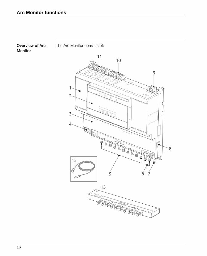
Overview of Arc
Monitor
The Arc Monitor consists of:
7
8
11
12
13
9
10
65
4
3
2
1
16
Arc Monitor functions
1: Arc Monitor The Arc Monitor is the heart in the system and handles signalling and detec-
tion. The HMI handles conditions, errors, and more. The system can be con-
figured to trip selected breakers, depending on which sensor detects light.
The DIP-switches that take care of this function also handle settings like
auto-reset and Current Sensing Units. Energy is stored in the Arc Monitor for
operation up to 0.2 s if the supply voltage fails. This is sufficient to close the
tripping contacts even during a short time of power loss.
2: Human Machine
Interface, HMI
The Human Machine Interface is used for all communication with the user
and also to confirm any changes. It can be mounted both on the product and
on the cabinet door. This is preferred to be able to get information about trips
without opening the cabinet after a trip.The HMI has a non-erasable memory
which holds trip logs and error logs even after power loss including a time
stamp.
The Arc Monitor can handle a second HMI module.
1, Arc Monitor 8 HMI external connection
2 Human Machine Interface, HMI 9 Power supply
3 Extension module plug in area 10 Solid state tripping contacts
4 DIP switch 11 Signal relays
5 Detector inputs 12 Detector (not included with the Arc Monitor)
6 Current Sensing Unit, CSU, inputs
13 Extension (option)
7 Current Sensing Unit, CSU, output
17

Arc Monitor functions
4: DIP switch The DIP switch is a physical switch on the Arc Monitors front.
DIP switches are used to activate the CSU, auto reset and assigning trip
contacts.
5: Detector Inputs Detector inputs are used to connect the detectors to the Arc Monitor.
6: Current Sensing
Unit input
The Current Sensing Unit (CSU) is an accessory needed only in those few
specific applications where strong light is expected on a regular basis. Cur-
rent Sensing Units are connected with an optical fibre using light as signal for
normal current. If the connection is removed by accident, the system ignores
the CSU and will react only on an arc flash.
Note!
DIP Switch 1 or/and 2 must be configured if the CSU is in use.
To read more about the CSU configuration; See the chapter “One (1) CSU connected” on page - 44
7: Current Sensing
Unit output
This output is used to pass the CSU signal forward to another Arc Monitor.
8: External HMI
connection
HMI can be mounted separately or a second module can be connected
(option).
Note!
Only use the included three meter (118 inch) cable for communication.
To learn more about the HMI functions; See the chapter “Human Machine Interface, functions” on page - 61.
18

Arc Monitor functions
10: Solid state
tripping contacts
The three solid state trip contacts, K4, K5 and K6 are used to trip the circuit
breakers.This will stop the energy from feeding the arc.
At normal condition:
• K4 Open, no arc detected
• K5 Open, no arc detected
• K6 Open, no arc detected
11: Signal Relays The Internal Relay Fault (IRF), K1 indicates the system status. At normal con-
dition the K1 is energized and signals that no diagnostics error is detected
on the Arc Guard System.
The two trip signal relays, K2 and K3 are used to signal when a trip occurs.
The relays can be used to activate an alarm or to pass the trip information to
a supervised system.
The signal relays are called K2 and K3.
• K2 de-energized, no arc detected
• K3 de-energized, no arc detected
If the system is configured for manual reset, K2 and K3 are energized until
the user is resets them on the Human Machine Interface (HMI) in the trip
notification window. If the system is configured for auto reset, K2 and K3 are
energized until the arc disappears.
12: Detectors The detectors are used to detect the intensive light from an arc and transfer
it to the Arc Guard System. The detectors are using fibre-optics and are
guaranteed that they will react on the correct light intensity. For this reason,
the cables are not to be modified in any way.
19
Arc Monitor functions
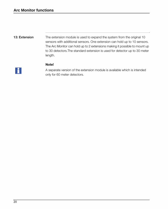
13: Extension The extension module is used to expand the system from the original 10
sensors with additional sensors. One extension can hold up to 10 sensors.
The Arc Monitor can hold up to 2 extensions making it possible to mount up
to 30 detectors.The standard extension is used for detector up to 30 meter
length.
Note!
A separate version of the extension module is available which is intended
only for 60 meter detectors.
20
Installation
Chapter 4: Installation
Introduction This chapter describes how to install the Arc Monitor and set up the system.
Also in this chapter are examples in placing detectors and general informa-
tion concerning the products.
Installation of Arc Monitor is performed in steps. After finishing one step you
proceed to the next one. The sequence is mandatory.
Note!
The Arc Monitor has 10 detector inputs. If your system needs more inputs
then you will need to use additional extension modules.
Installation
procedure
Installation procedure consists of the following five steps:
1. Getting started
2. Mounting
3. Connecting electrical connections
4. Configuration
5. Controlling
Prerequisites
Warning!
The reader should have knowledge and follow the applicable safety laws and
standards as well as local safety instructions.
21

Installation
Tools required To mount the Arc Monitor the following tools are required:
• Screwdriver, 2.5 x 0.6 mm (0.98 x 0.23 inch)
• Phillips screwdriver 4.3/2
• Drill 5 mm (0.196 inch), in case of wall mounting.
Mounting and
connecting the
Arc Monitor to the
system
This is a summarize of the complete procedure in mounting and connecting
the Arc Monitor.
Warning!
Make sure that supply voltage is switched off before mounting and connect-
ing the Arc Monitor!
To mount and connect the Arc Monitor do the following steps:
1. Mount the Arc Monitor
2. Mount and connect external HMI (option). See page 26
3. Connect extensions X2, X3 (option). See page 33
4. Place and mount the optical detectors. This installation guide contains exam-ples for placing the detectors and information how to mount. See page 27
5. Connect optical detectors to the Arc Monitor and extensions (option).
6. Connect optical cables (option) from current sensing units, CSU to lower right hand side of base unit (X1:21-22). See page 34
7. Connect optical cable (option) to output for additional Arc Monitor (X1:23)
8. Connect electrical connections. See page 36
9. Configure the system by setting the DIP switches. See page 39
10. Supply the system with power.
11. Go through Start-Up sequence in Human Machine Interface, HMI. See page 47
12. Controlling the detectors and the system. See page 51
22
Installation
Getting started
Introduction This chapter describes instructions how to receive and check the Arc Moni-
tor. Do the following steps:
Receiving and
checking
1. Turn the package with the correct side up.
2. Remove the transport casing.
3. Visually inspect the Arc Monitor.
4. Check that all items are included, according to the delivery document.
List of contents Check the contents in this package as follow:
• Arc Monitor
• Connection cable 3 meter (118 inch) for external Human Machine Interface, HMI
• Plastic nut for mounting external HMI
• Sealing for mounting external HMI
• Label for covering HMI contact on Arc Monitor, (only if external HMI is used)
• User manual on CD
• Quick installation guide
Note!
This package is a basic start kit. If you need more according for your system
needs then contact your local supplier.
Intermediate stor-
age
Until the Arc Monitor is mounted it should be stored in its original package.
23
Installation
Mounting
Introduction This chapter describes the procedure to mount and connect the Arc Monitor.
The procedure is divided into following components:
• Arc Monitor
• Human Machine Interface, HMI
• Detectors
• Extension
• Current Sensing Unit, CSU
Placing Arc Moni-
tor
The Arc Monitor can be mounted anywhere in the switchgear, for example in
the breaker cubicle or in a separate control cabinet.
Mounting Arc
Monitor
This section describes how to mount the Arc Monitor at its location.
The Arc Monitor can be mounted on:
• A wall
• DIN Rail
24

Installation
Mounting on wall Follow the steps below to mount the Arc Monitor on the wall:
1. Predrill holes in wall to fit screws 5M. See figure above for dimensions.
2. Place the Arc Monitor on the wall.
3. Screw in each corner of the monitor.
4. Use a torque wrench and torque the screws to 0,9 Nm.
Mounting on a DIN
rail
Follow this procedure to mount the Arc Monitor on a DIN rail:
1. Hook the Arc Monitor to the DIN rail.
2. Pull the barrier down, between detector 5 and 6.
3. Snap the Arc Monitor on to the rail then release the barrier.
0,9 Nm
217
187,5
M5
3
1
2
35
7,5 / 15
25
Installation
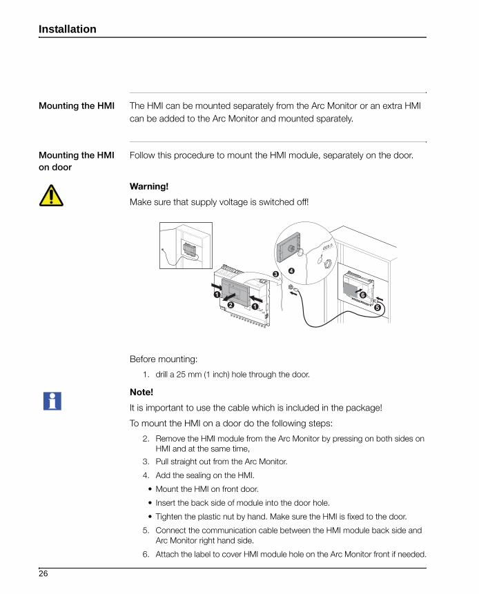
Mounting the HMI The HMI can be mounted separately from the Arc Monitor or an extra HMI
can be added to the Arc Monitor and mounted sparately.
Mounting the HMI
on door
Follow this procedure to mount the HMI module, separately on the door.
Warning!
Make sure that supply voltage is switched off!
Before mounting:
1. drill a 25 mm (1 inch) hole through the door.
Note!
It is important to use the cable which is included in the package!
To mount the HMI on a door do the following steps:
2. Remove the HMI module from the Arc Monitor by pressing on both sides on HMI and at the same time,
3. Pull straight out from the Arc Monitor.
4. Add the sealing on the HMI.
• Mount the HMI on front door.
• Insert the back side of module into the door hole.
• Tighten the plastic nut by hand. Make sure the HMI is fixed to the door.
5. Connect the communication cable between the HMI module back side and Arc Monitor right hand side.
6. Attach the label to cover HMI module hole on the Arc Monitor front if needed.
1
12
6
5
43
Ø25,5
26

Installation
Mounting the
Optical detector
This section is about optical detectors and the mounting is described using
examples:
• Where to positioning the detectors.
• How the detectors are mounted on busbars system.
This section also describes how to connect the detectors to the Arc Monitor.
Decide where to position the detectors on the basis of knowledge of your
own system. The main issue is to cover all components that might suffer from
an arc.
Warning!
Make sure that supply voltage is switched off!
Note!
Excess plastic fibre cable should be wound up and kept as a ring with a
diameter of at least 100 mm (4 inches).
The plastic fibre cables are not to be bent in a loop with a radius of less than
10 mm (0.4 inches) occasionally and 45 mm (1.8 inches) for a long period of
time.
Min 100mm
27
Installation
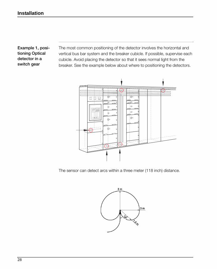
Example 1, posi-
tioning Optical
detector in a
switch gear
The most common positioning of the detector involves the horizontal and
vertical bus bar system and the breaker cubicle. If possible, supervise each
cubicle. Avoid placing the detector so that it sees normal light from the
breaker. See the example below about where to positioning the detectors.
The sensor can detect arcs within a three meter (118 inch) distance.
28

Installation
Example 2,
Mounting Optical
detector in an
apertures cubicle
A single detector is able to monitor the busbars in both the apparatus cubicle
and the respective cable.
This is an example about how to mount optical detectors with the mounting
kit.
Do the following steps to mount the detector on a busbar.
1. Attach the detector to the mounting bracket (1SFA663 006 R100x) before it is attached to the cubicle.
2. The bend of mounting bracket should point downwards.
3. Attach the detector to the upper side of the bracket. See figure below.
4. Use a 2.5 mm (0.1 inch) wide cable strap.
5. Place the strap on the rear groove of the detector head and around the notches in the mounting bracket.
6. Attach the detector bracket onto the cubicle frame. See the figure below.
7. The hole in the mounting bracket is for M5 thread rolling screws or 5.5 self tapping screws.
29

Installation
Example 3,
Mounting in a cir-
cuit breaker cubi-
cle
In a circuit-breaker cubicle there is a risk of detecting breaking arcs uninten-
tionally, if the detector is placed above the busbars. In such a cubicle it is
better to place the detector at the bottom, see the figure below.
• Use the same mounting bracket as for top mounting but the bend is turned upwards and the detector placed on the upper side.
• Drill a hole 20 mm (0.79 inches) in front of the busbars, where the detector can be located.
30
Installation
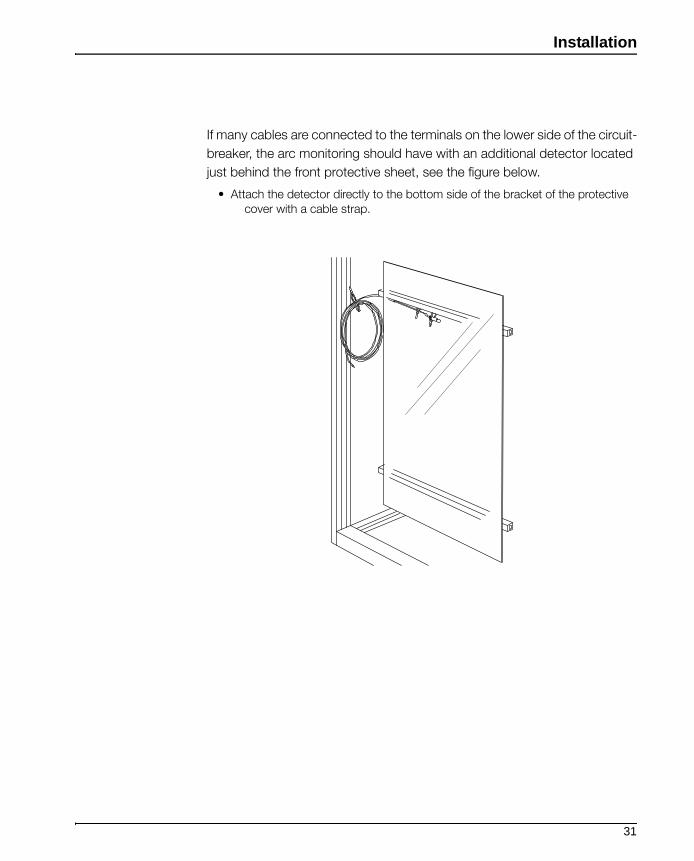
If many cables are connected to the terminals on the lower side of the circuit-
breaker, the arc monitoring should have with an additional detector located
just behind the front protective sheet, see the figure below.
• Attach the detector directly to the bottom side of the bracket of the protective cover with a cable strap.
31
Installation
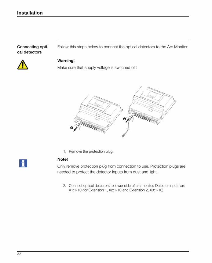
Connecting opti-
cal detectors
Follow this steps below to connect the optical detectors to the Arc Monitor.
Warning!
Make sure that supply voltage is switched off!
1. Remove the protection plug.
Note!
Only remove protection plug from connection to use. Protection plugs are
needed to protect the detector inputs from dust and light.
2. Connect optical detectors to lower side of arc monitor. Detector inputs are X1:1-10 (for Extension 1, X2:1-10 and Extension 2, X3:1-10)
2
1
32

Installation
Connecting exten-
sion module
(option)
Follow this steps to connect extension module to the Arc Monitor:
Warning!
Make sure that supply voltage is switched off!
1. Remove the protection part.
2. Mount the extension module into the contact of the Arc Monitor.
3. Secure the extension module using screwdriver torque 0.6 NM.
To connect second extension module:
1. Remove the protection part from the second extension module.
2. Mount the extension module into the contact of the Arc Monitor.
3. Secure the extension module using screwdriver torque 0.6 NM.
4. Cover the X2 text with label X3 which comes with the addtional extension module.
30.6 Nm
2x
1
2
0.6 Nm2x
X2X3
X1
33

Installation
Connecting CSU
cable
Follow this steps to connect CSU cable to the Arc Monitor:
Warning!
Make sure that supply voltage is switched off!
Follow this steps to connect CSU cable:
1. Remove the protection plug.
2. Connect current sensing cable to lower side right side of Arc Monitor by pressing.
Current sensing units (CSU) inputs are X1: 21, 22.
Current sensing units (CSU) outputs are X1: 23.
Note!
Before the system is ready to use, a DIP switch configurations are needed.
For more information, see the chapter “Configurations” on page - 39.
2
1
34
Installation
Electrical connections
Introduction This chapter describes how to connect the electrical connections to the Arc
Monitor and to the Arc Guard System.
Warning!
Make sure that supply voltage is switched off!
Connecting HMI To read about connecting HMI; See the chapter “Mounting the HMI on door” on page - 26.
Connecting opti-
cal detector
To read about connecting optical detector ; See the chapter “Connecting optical detectors” on page - 32.
Connecting exten-
sion module
(option)
To read about connecting extension modules; See the chapter “Connecting extension module (option)” on page - 33.
Connecting Cur-
rent Sensing Unit
(option)
To read about connecting Current Sensing Unit ; See the chapter “Connect-ing CSU cable” on page - 34.
35
Installation
Electrical connec-
tions
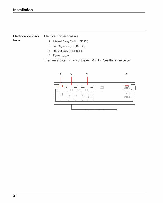
Electrical connections are:
1. Internal Relay Fault, ( IRF, K1)
2 Trip Signal relays, ( K2, K3)
3 Trip contact, (K4, K5, K6)
4 Power supply
They are situated on top of the Arc Monitor. See the figure below.
1 2 3 4
36
Installation
Connecting the
Arc Monitor
Warning!
Make sure that supply voltage has been switched off!
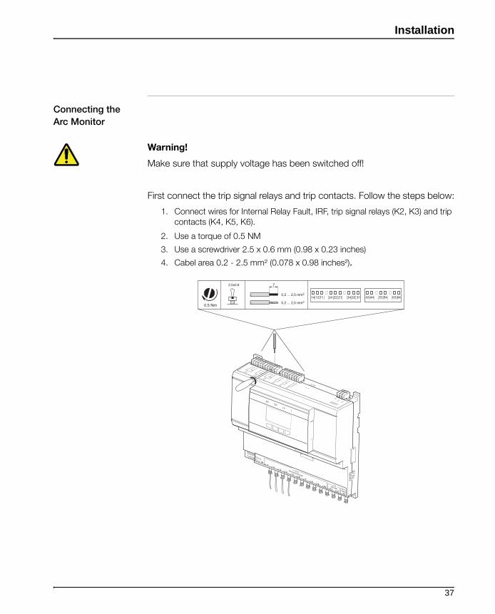
First connect the trip signal relays and trip contacts. Follow the steps below:
1. Connect wires for Internal Relay Fault, IRF, trip signal relays (K2, K3) and trip contacts (K4, K5, K6).
2. Use a torque of 0.5 NM
3. Use a screwdriver 2.5 x 0.6 mm (0.98 x 0.23 inches)
4. Cabel area 0.2 - 2.5 mm² (0.078 x 0.98 inches²).
0,5 Nm
2,5x0,6 7
0,2 ... 2,5 mm2
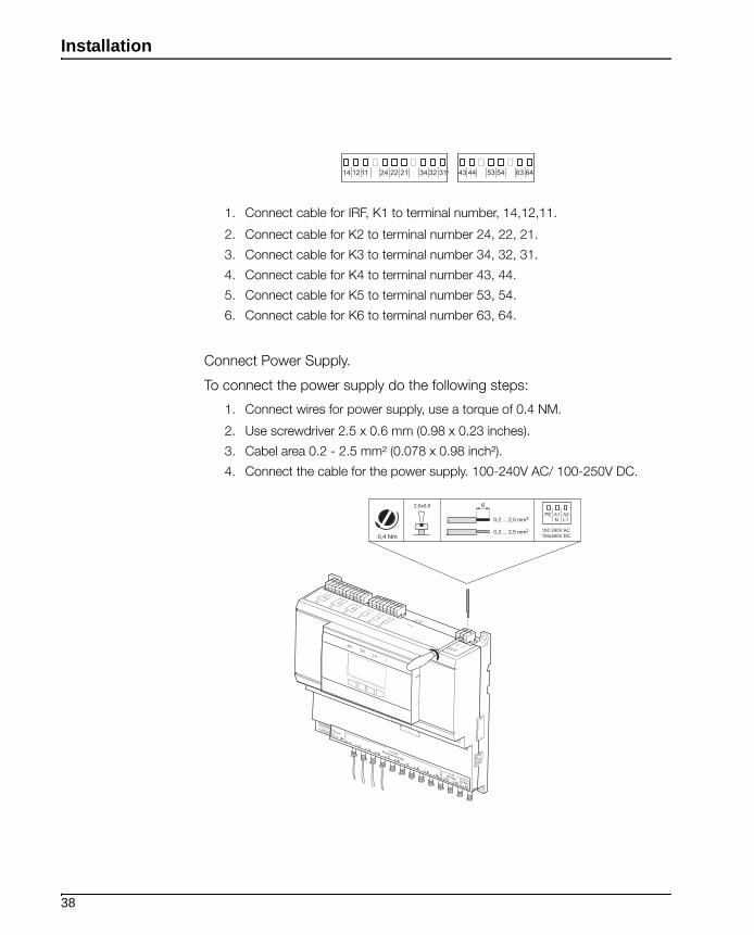
0,2 ... 2,5 mm214 12 11 24 22 21 34 32 31 43 44 53 54 63 64
37
Installation
1. Connect cable for IRF, K1 to terminal number, 14,12,11.
2. Connect cable for K2 to terminal number 24, 22, 21.
3. Connect cable for K3 to terminal number 34, 32, 31.
4. Connect cable for K4 to terminal number 43, 44.
5. Connect cable for K5 to terminal number 53, 54.
6. Connect cable for K6 to terminal number 63, 64.
Connect Power Supply.
To connect the power supply do the following steps:
1. Connect wires for power supply, use a torque of 0.4 NM.
2. Use screwdriver 2.5 x 0.6 mm (0.98 x 0.23 inches).
3. Cabel area 0.2 - 2.5 mm² (0.078 x 0.98 inch²).
4. Connect the cable for the power supply. 100-240V AC/ 100-250V DC.
14 12 11 24 22 21 34 32 31 43 44 53 54 63 64
PE A1 A2N L1
0,4 Nm
2,5x0,6
0,2 ... 2,5 mm2
0,2 ... 2,5 mm2
6
38
Installation
Configurations
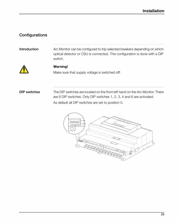
Introduction Arc Monitor can be configured to trip selected breakers depending on which
optical detector or CSU is connected. This configuration is done with a DIP
switch.
Warning!
Make sure that supply voltage is switched off!
DIP switches The DIP switches are located on the front left hand on the Arc Monitor. There
are 8 DIP switches. Only DIP switches 1, 2, 3, 4 and 6 are activated.
As default all DIP switches are set to position 0.
1 2 3 4 5 6 7 8
39
Installation
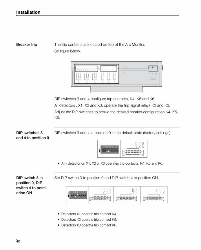
Breaker trip The trip contacts are located on top of the Arc Monitor.
Se figure below.
DIP switches 3 and 4 configure trip contacts, K4, K5 and K6.
All detectors , X1, X2 and X3, operate the trip signal relays K2 and K3.
Adjust the DIP switches to achive the desired breaker configuration K4, K5,
K6.
DIP switches 3
and 4 to position 0
DIP switches 3 and 4 in position 0 is the default state (factory settings).
• Any detector on X1, X2 or X3 operates trip contacts, K4, K5 and K6.
DIP switch 3 in
position 0, DIP
switch 4 to posti-
otion ON
Set DIP switch 3 to position 0 and DIP switch 4 to position ON.
• Detectors X1 operate trip contact K4.
• Detectors X2 operate trip contact K5.
• Detectors X3 operate trip contact K6.
ON
1 2 3 4 5 6 7 8
X1
X2X3
43
K4Trip
44 53
K5Trip
54 63
K6Trip
64
ON
1 2 3 4 5 6 7 8
X1
X2X3
X1
X2X3
X1
X2X3
43
K4Trip
44 53
K5Trip
54 63
K6Trip
64 43
K4Trip
44 53
K5Trip
54 63
K6Trip
64 43
K4Trip
44 53
K5Trip
54 63
K6Trip
64
40
Installation
DIP switch 3 to
position ON and
DIP switch 4 to
position 0.
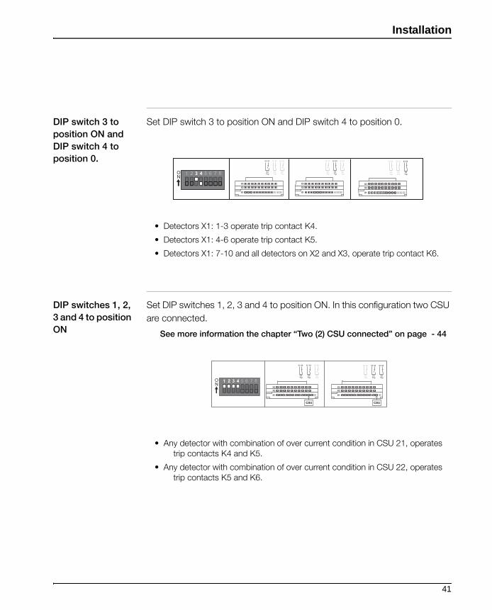
Set DIP switch 3 to position ON and DIP switch 4 to position 0.
• Detectors X1: 1-3 operate trip contact K4.
• Detectors X1: 4-6 operate trip contact K5.
• Detectors X1: 7-10 and all detectors on X2 and X3, operate trip contact K6.
DIP switches 1, 2,
3 and 4 to position
ON
Set DIP switches 1, 2, 3 and 4 to position ON. In this configuration two CSU
are connected.
See more information the chapter “Two (2) CSU connected” on page - 44
• Any detector with combination of over current condition in CSU 21, operates trip contacts K4 and K5.
• Any detector with combination of over current condition in CSU 22, operates trip contacts K5 and K6.
ON
1 2 3 4 5 6 7 8
X2X3
X2X3
X2X3
X1 X1 X1
43
K4Trip
44 53
K5Trip
54 63
K6Trip
64 43
K4Trip
44 53
K5Trip
54 63
K6Trip
64 43
K4Trip
44 53
K5Trip
54 63
K6Trip
64
ON
1 2 3 4 5 6 7 8K4Trip
K5Trip
K6Trip
43 44 53 54 63 64
K4Trip
K5Trip
K6Trip
43 44 53 54 63 64
CSU CSU
X1
X2X3
X1
X2X3
41
Installation
Manual/Auto reset
configuration
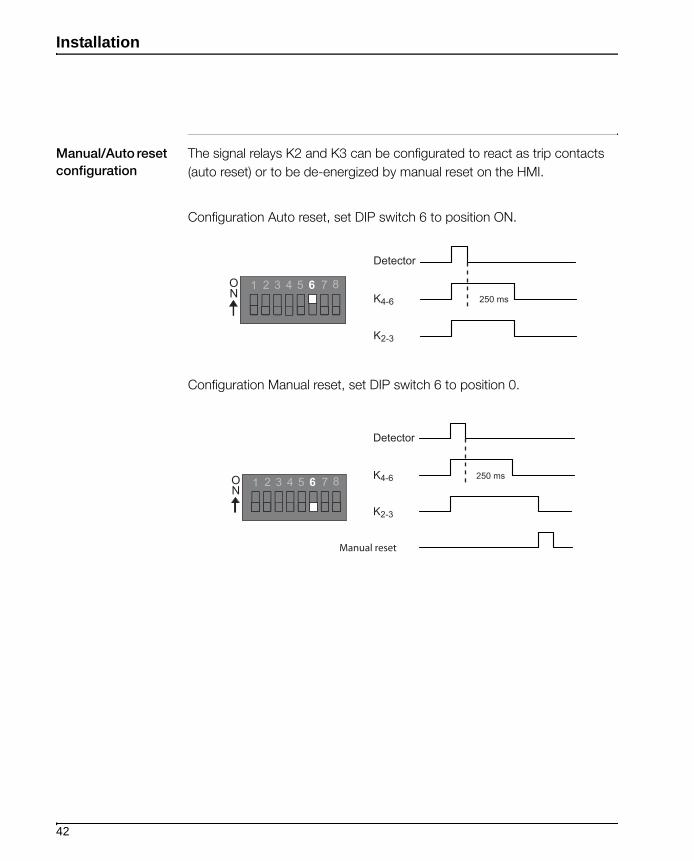
The signal relays K2 and K3 can be configurated to react as trip contacts
(auto reset) or to be de-energized by manual reset on the HMI.
Configuration Auto reset, set DIP switch 6 to position ON.
Configuration Manual reset, set DIP switch 6 to position 0.
Detector
K4-6
K2-3
250 ms
ON
1 2 3 4 5 6 7 8
Detector
K4-6
K2-3
250 msON
1 2 3 4 5 6 7 8
Manual reset
42
Installation
Current Sensing
Unit(option)
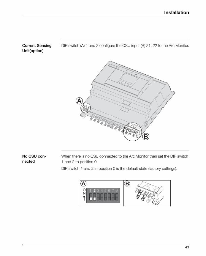
DIP switch (A) 1 and 2 configure the CSU input (B) 21, 22 to the Arc Monitor.
No CSU con-
nected
When there is no CSU connected to the Arc Monitor then set the DIP switch
1 and 2 to position 0.
DIP switch 1 and 2 in position 0 is the default state (factory settings).
B
A
ON
1 2 3 4 5 6 7 8
BA
43

Installation
One (1) CSU con-
nected
If there is one (1) CSU connected to the CSU input X1, 21 then set the DIP
switch 1 to position ON.
Two (2) CSU con-
nected
If there are two (2) CSUs connected to the CSU input 21 and 22 then set the
DIP switch 1 and 2 to position ON.
Note!
The CSU cable is connected before configuration is made.
For more information how to connect CSU cables, see the chapter “Con-necting CSU cable” on page - 34.
ON
1 2 3 4 5 6 7 8
ON 1 2 3 4 5 6 7 8
44

Installation
Power on to the
Arc Monitor
Warning!
Working with high voltage is potentially lethal.
Before switching the power supply on follow the steps below:
1. Check your installation.
2. Check that electrical connections are orderly connected.
3. Check that the configuration is set for your system.
4. Make sure the supply voltage is suitable (100-240V AC/DC 50/60Hz).
5. Make sure you do not leave any working tools in the switching gear.
When the Arc Monitor is connected to supply voltage, then it is on.
Checking power
on Arc Monitor
When the Arc Monitor is on check the following :
• Green LEDs "Power" on left side of detector inputs is lit.
• Green LED "Power" on HMI is lit.
• HMI is showing text.
45
Installation
Add/Remove
module from the
Arc Monitor or
changing configu-
ration
Warning!
Make sure that supply voltage is switched off!
To add/remove a module to the system do the steps below:
1. Remove power to the Arc Monitor.
2. Physically add/remove a module to the Arc Monitor.
3. Ensure DIP Switches are set correctly.
4. Power on.
5. Follow Start-Up sequence.
The Arc Monitor requires configuration of the system and its modules to
work.
The Human Machine Interface, HMI automatically guide the user through a
Start-Up Sequence.
Note!
For more information concerning Start-Up Sequence, See the chapter “Set-tings” on page - 47.
46

Installation
Settings
Introduction This chapter describes the five mandatory steps to succeed in setting the
system. All settings are done in the Human Machine Interface, HMI.
Settings are made only with the power on.
Start-Up
Sequence
Installation of the Arc Monitor requires configuration of the system and its
modules to work. This start-up is mandatory. The same start-up occurs
when operating the Arc Monitor for the first time and when adding/removing
modules for the Arc Monitor. The Human Machine Interface (HMI) automati-
cally go through the different configuration steps. To do the Start-Up
sequence follow the steps below:
1. Set language of the system menu
2. Set time and date
3. Confirm connected modules
4. Check DIP Switches
5. Final confirmation
Note!
The system will not require the Start-Up sequence in the event of a power
loss.
Step 1: Setting
menu
language
This is the first step to make the system work after installing the Arc Monitor.
Use this procedure to choose the language of the system menu during start-
up.
In the Start-Up menu do the following:
1. Mark the language to use and press OK.
2. Confirm by pressing YES.
47

Installation
Available
languages
Languages available in the system are:
• english (us/uk)
Step 2: Setting
time
This is the second step to make the system work after installing the Arc
Monitor. Use this procedure to set the time and date in the system.
In window, 3.4 Set Time do the following:
1. Scroll to correct hour, press OK.
2. Scroll to correct minutes, press OK.
3. Scroll to correct day, press OK.
4. Scroll to correct month, press OK.
5. Scroll to correct year, press OK.
Step 3: Confirming
connected
modules
This is the third step to make the system work after installing the Arc Monitor.
Use this procedure to confirm connected modules during start up.
In window, 3.1.1 View connected do the following:
1. Check the list of modules and if all modules are included, press Yes.
2. If all modules not are included, press No. See next step 3, below.
Warning!
Make sure that supply voltage is switched off!
3. Remove the power and check the connections to the modules.
4. Power on.
5. Start-Up sequence will start again with step 1, page 47, Setting menu lan-guage.
48
Installation
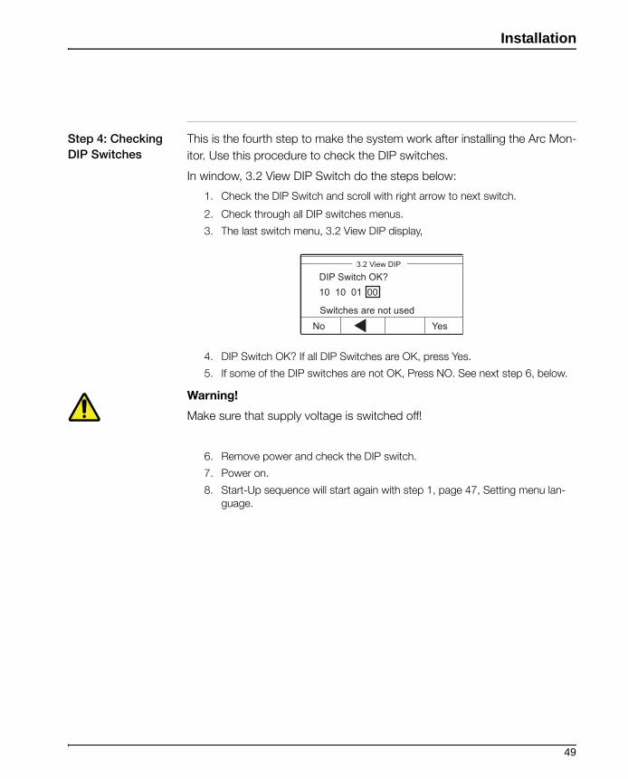
Step 4: Checking
DIP Switches
This is the fourth step to make the system work after installing the Arc Mon-
itor. Use this procedure to check the DIP switches.
In window, 3.2 View DIP Switch do the steps below:
1. Check the DIP Switch and scroll with right arrow to next switch.
2. Check through all DIP switches menus.
3. The last switch menu, 3.2 View DIP display,
4. DIP Switch OK? If all DIP Switches are OK, press Yes.
5. If some of the DIP switches are not OK, Press NO. See next step 6, below.
Warning!
Make sure that supply voltage is switched off!
6. Remove power and check the DIP switch.
7. Power on.
8. Start-Up sequence will start again with step 1, page 47, Setting menu lan-guage.
3.2 View DIP
No YesSwitches are not used
DIP Switch OK?10 10 01 00
49
Installation
Step 5: Final con-
firmation
This is the fifth step to make the system work after installing the Arc monitor.
Use this procedure to confirm that all Start-Up settings are done.
In the Start-up menu do the steps below:
1. Press OK. All settings done. The system is now ready to run accordingly and will return to Start window.
2. Check that the green LEDs "Power" on left side of extension modules on Arc Monitor is lit.
3. Check that the Green LED "Power" on HMI is lit.
4. Check that HMI is showing text.
Note!
After completed Start-Up Sequence at the first time installation the complete
sytem needs checking.
This includes checking that the detectors and HMI works as intended.
For more information how to check the detectors and HMI, See the chapter “Controlling” on page - 51.
50

Installation
Controlling
IntroductionNote!
Do the test after installation and before the Arc Monitor is used!
This test is done for each installed detector and the Arc Monitor.The test will
check that the detectors react to a simulated arc and the HMI will display a
notification window showing which detector and which circuit breaker is
tripped. The breaker that is connected to the Arc Monitor should trip.
Use a camera flash to simulate an arc. At normally sensitivity the Arc Monitor
will react to the flash.
Note!
Flash specifications to simulate an arc, 16 (m) guide no. 21 DIN/100 ASA.
Testing the instal-
lation
Repeat the following steps to check all installed detectors separately:
1. Simulate an arc by using a camera flash.
2. Set the camera flash to approximately 0.5 ms.
3. Place the camera flash at a distance between 1.5 -2 meters (60-80 inches) from the detector.
4. Make sure no object is standing in the way.
5. Point the camera flash towards the detector.
6. Press the flash test button.
Do the following steps to check the Arc Monitor:
1. Check the HMI display.
2. If the detector reacts correctly and causes a trip then it should show on the HMI display as a notification window.
3. The notification window shows, Trip has Occurred, which detector, which trip contact, at what time and date.
4. The breaker that is connected to the Arc Monitor should trip, depending on the configuration.
5. At the notification window, If manual reset is configured, press Reset. If auto reset is configured, press Menu
51

Installation
52

Maintenance
Chapter 5: Maintenance
Introduction The Arc Guard System requires maintenance once every year.
The yearly maintenance includes checking detectors, The Arc Monitor and
the light from CSU (option).
Maintenance To check the detectors and the Arc Monitor repeat the following steps:
1. Simulate an arc by using a camera flash.
2. Set the camera flash to approximately 0.5 ms.
3. Place the camera flash at a distance between 1.5 -2 meters (60-80 inches) from the detector.
4. Make sure no object is standing in the way.
5. Point the camera flash towards the detector.
6. Press the flash test button.
Do the following steps to check the Arc Monitor:
1. Check the HMI display.
2. If the detector reacts correctly and causes a trip then it should show on the HMI display as a notification window.
3. The notification window shows, Trip has Occurred, which detector, which trip contact, at what time and date.
4. The breaker that is connected to the Arc Monitor should trip, depending on the configuration.
5. At the notification window, If manual reset is configured, press Reset. If auto reset is configured, press Menu.
53

Maintenance
Note!
In order to prevent a shut-down of the whole switchgear during the mainte-
nance process, replace the breakers which are connected to the Arc Monitor
with test breakers. This can be done by replacing the terminal to K4, K5, K6
with the test breakers.
Do remember to replace the test breakers with terminal breaker K4, K5, K6
after testing!
The maintenance procedure to check the detectors and Arc Monitor is the
same as for a Start-Up of the system for the first time.
Note!
See in chapter Installation, “Controlling” on page - 51
To check the light from Current Sensing Unit, CSU.
Perform a manual diagnostic via the HMI to check if the light from CSU is
degenerating. This will show as a notification window in HMI with an Error
code.
Note!
See “2.2 Perform Diagnostics” on page - 68, about how to perform a man-ual diagnostics.
See “List of error codes” on page - 57, about error codes.
54
Trouble shooting
Chapter 6: Trouble shooting
Introduction This chapter describes how to handle errors in the system and what mea-
sures to take. That includes the handling error log, list of error codes and how
to contact ABB.
Requirements Trouble shooting should be done by authorized personnel who are familiar
with the Arc Guard System, the setup as well as the environment where it is
located.
Troubleshooting Trouble shooting should take into consideration:
• History, including events just before an arc
• Situation, circumstances when an arc occurred
• Environment, temperature, vibrations, power supply, electrical/magnetic distur-bances
• How an arc is indicated and nature of its occurrence
• The different Arc Guard System modules and all connections
Handling Error log This section presents diagnostics and describes how to handle the error log.
It includes view logs and error codes.
Diagnostics The Arc Guard Systems is often operated without any personnel present.
The error logging function is a way to store information about past events for
future reference in order to facilitate trouble shooting. Performing diagnostics
is a check on the system status and its error events.
Error event An error event indicates an error in the system. Example of error events is:
• Overcurrent for a long time period.
• Optical detectors that detect light for a long time period.
• DIP switch is changed physically while Arc Monitor is powered.
55
Trouble shooting
• HMI display has lost contact and can not communicate with Arc Monitor.
Error Log During diagnostics the error events are logged in the Error Log. In the Error
Log the error events are represented by error messages. Each message
includes a code that gives information about the specific occurred event and
the time stamp it occurred.
The log is a circular buffer. It stores nine error events. The oldest will be over-
written.
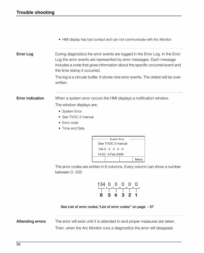
Error indication When a system error occurs the HMI displays a notification window.
The window displays are:
• System Error
• See TVOC-2 manual
• Error code
• Time and Date
The error codes are written in 6 columns. Every column can show a number
between 0 -255
See List of error codes,“List of error codes” on page - 57
Attending errors The error will exist until it is attended to and proper measures are taken.
Then, when the Arc Monitor runs a diagnostics the error will disappear.
System Error
Menu
See TVOC-2 manual
134 0 0 0 0 014:02 3-Feb-2009
56
Trouble shooting
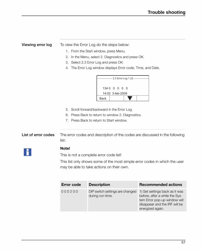
Viewing error log To view the Error Log do the steps below:
1. From the Start window, press Menu.
2. In the Menu, select 2. Diagnostics and press OK.
3. Select 2.3 Error Log and press OK.
4. The Error Log window displays Error code, Time, and Date.
5. Scroll forward/backward in the Error Log.
6. Press Back to return to window 2. Diagnostics.
7. Press Back to return to Start window.
List of error codes The error codes and description of the codes are discussed in the following
list:
Note!
This is not a complete error code list!
This list only shows some of the most simple error codes in which the user
may be able to take actions on their own.
2.3 Error Log 1 (3)
Back
134 0 0 0 0 014:02 3-feb-2009
Error code Description Recommended actions
0 0 0 2 0 0 DIP switch settings are changed during run-time.
1) Set settings back as it was before, after a while the Sys-tem Error pop-up window will disappear and the IRF will be energized again.
57

Trouble shooting
0 72 0 0 0 0 CSU21:
1)Optional cable is damaged.
2)Overcurrent longer than 10s.
3) Detector input damage at Arc Monitor.
4) LED at CSU is damaged.
Check that optional cable from CSU is not damaged or crushed.
Check current level setting if setting is too low, then CSU is indicating overcurrent too long time period. Increase level and see that you get light from CSU, if no light from CSU then LED at CSU is damaged. If none of this then detector input at Arc Monitor is corrupt.
0 80 0 0 0 0 CSU22:
1)Optional cable is damaged
2)Overcurrent longer than 10s
3) Detector input damage at Arc Monitor
4) CSU LED damage
See Error code 0 8 0 0 0 0.
2 0 0 0 0 0 CSU21:
Degenerated LED at CSU. The CSU LED degeneration will only be tested by a manual Diagnos-tic Test (2.2 Perform Diagnostics) made from HMI.
CSU LED degeneration will not be tested by periodically diag-nostics.
CSU should be replaced due to degenerated LED at CSU.
4 0 0 0 0 0 CSU22:
Degenerated LED at CSU. Diag-nostic test will only be triggered by a manual Diagnostic Test made from HMI.
8 0 0 0 0 0 Lost contact with HMI.
32 0 0 0 0 0 Long light detection. A light detector has detected light during more than 10s. Can the light detector have been damaged or is there con-stantly light leaking into the cabinet.
Error code Description Recommended actions
58

Trouble shooting
0 1 0 0 0 0 X3 present, is not the correct module.
Extension module can have been switched. Wrong ID of Extension module, X2 and X3 can have been switched.
Check if the Extension module can have switched places.
0 2 0 0 0 0 No contact with X3, module can have dropped off.
Check the Extension module.
0 0 2 0 0 0 X2 present, not correct module. Extension modules can be switched.
Check if the Extension module can have switched places.
0 0 4 0 0 0 No contact with X2, module can have dropped off.
Check the extension module, X2
Error code Description Recommended actions
59

Trouble shooting
ABB support
Introduction If you have problem with your Arc Guard System, contact ABB for support.
Contact informa-
tion
ABB AB
Cewe Control
SE-721 61 VÄSTERÅS, Sweden
Telephone +46 21 32 07 00
Telefax +46 21 12 60 00
www. abb.com/lowvoltage
Providing informa-
tion
To get faster support when contacting ABB support it is beneficial to be pre-
pared to answer the following questions:
• Description of how the error occured.
• Which Arc Guard System modules are used, setup and configuration.
• Readings on LEDs and display.
• Output signals.
• What is the general situation.
• Application, location, ambient conditions.
• What has happened, situation before error, any event that happened in connec-tion with error.
• Have you done trouble shooting? What did you check?
• Which are your findings?
Note!
It is also important to know the serial number.
See label on Arc Monitor.
To get the Arc Monitors Revision Information, see chapter HMI functions, “2 Diagnostics” on page - 65
60
Human Machine Interface, functions
Chapter 7: Human Machine Interface, functions
Introduction The Human Machine Interface, HMI is used for all communication with the
user and also to confirm any changes.
If power is lost (max 48 hours) the Time and Date will be restored. After very
long power interruptions the Time and Date are set to a default value and
needed to be set by the user.
This chapter consists of the following sections:
• Overview HMI
• HMI functions
• HMI Menus
Prerequisites
Note!
The reader should have knowledge and act according to applicable safety
laws and standards as well as local safety instructions.
61
Human Machine Interface, functions
Overview HMI
module
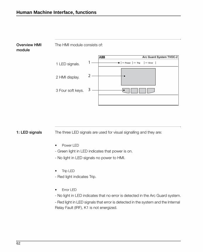
The HMI module consists of:
1: LED signals The three LED signals are used for visual signalling and they are:
• Power LED
- Green light in LED indicates that power is on.
- No light in LED signals no power to HMI.
• Trip LED
- Red light indicates Trip.
• Error LED
- No light in LED indicates that no error is detected in the Arc Guard system.
- Red light in LED signals that error is detected in the system and the Internal
Relay Fault (IRF), K1 is not energized.
Arc Guard System TVOC-2
Power ErrorTrip1
2
3
1 LED signals.
2 HMI display.
3 Four soft keys.
62
Human Machine Interface, functions
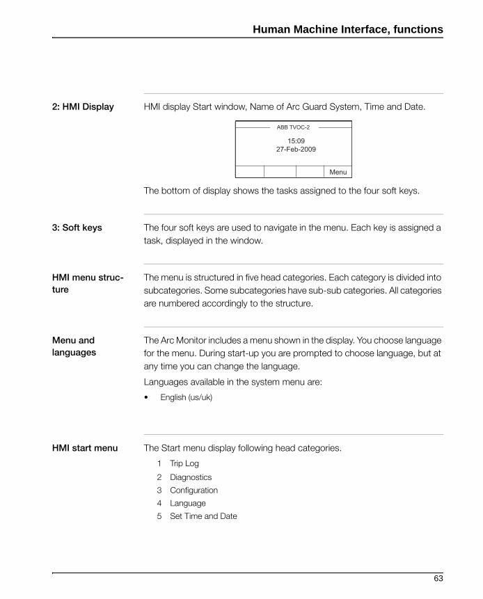
2: HMI Display HMI display Start window, Name of Arc Guard System, Time and Date.
The bottom of display shows the tasks assigned to the four soft keys.
3: Soft keys The four soft keys are used to navigate in the menu. Each key is assigned a
task, displayed in the window.
HMI menu struc-
ture
The menu is structured in five head categories. Each category is divided into
subcategories. Some subcategories have sub-sub categories. All categories
are numbered accordingly to the structure.
Menu and
languages
The Arc Monitor includes a menu shown in the display. You choose language
for the menu. During start-up you are prompted to choose language, but at
any time you can change the language.
Languages available in the system menu are:
• English (us/uk)
HMI start menu The Start menu display following head categories.
1 Trip Log
2 Diagnostics
3 Configuration
4 Language
5 Set Time and Date
ABB TVOC-2
Menu
15:0927-Feb-2009
63

Human Machine Interface, functions
1 Trip Log When the optical detectors detect arcs, the Arc Monitor reacts. The system
will trip the trip contacts according to the configuration on the DIP switches.
Arc Monitor is designed to save information about an arc in the Trip Log.
The Trip Log can store seven trips in a circular buffer, the oldest will be over-
written.
This section describes how to handle the Trip Log.
Trip notification
window
When a trip occurs a notification window will be displayed on the display.
The notification window display the following:
• Which detector reacted.
• Which trip contact tripped.
• Time and Date the arc occurred.
To reset the Trip Signal Relays, K2 and K3 do the following steps:
1 In the notification window press Reset.
2 The notification window disappears and the system returns to Start window.
3 The trip is stored in the Trip Log.
Note!
If Auto reset of K2 and K3 is configured at the DIP switches, the notification
window will appear at a trip but there is no need to reset. Then press Menu
to return to Start window.
Trip has occured
Reset
Detector X1 : 10
Breaker K4 K5
14:02 3-feb-2009
64
Human Machine Interface, functions
Checking the trip
log
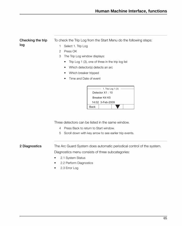
To check the Trip Log from the Start Menu do the following steps:
1 Select 1. Trip Log
2 Press OK
3 The Trip Log window displays:
• Trip Log 1 (3), one of three in the trip log list
• Which detector(s) detects an arc
• Which breaker tripped
• Time and Date of event
Three detectors can be listed in the same window.
4 Press Back to return to Start window.
5 Scroll down with key arrow to see earlier trip events.
2 Diagnostics The Arc Guard System does automatic periodical control of the system.
Diagnostics menu consists of three subcategories:
• 2.1 System Status
• 2.2 Perform Diagnostics
• 2.3 Error Log
1. Trip Log 1 (3)
Back
Detector X1 : 10
Breaker K4 K5
14:02 3-Feb-2009
65

Human Machine Interface, functions
2.1 System Status The system status displays the status of the system after a diagnos is made.
The window displays the following:
• System OK
• Diagnostics performed
• Time and Date
2.2 Perform Diag-
nostics
In addition to the systems automatic diagnostic, it is the possible to do a
manual one. To perform a manual diagnostic do the following steps:
1 From Start window, press Menu
2 Select 2. Diagnostics and press OK
3 In the 2. Diagnostics menu, select 2.2 Perform Diagnostics
4 Press OK for diagnostic test now
5 The window displays Performing diagnostics tests...
2.1 System status
OK
Diagnostics performed15:09 28-Feb-2009
System OK
2.2 Perform Diagnostic
Back OK
Press OK fordiagnostic test now.
66

Human Machine Interface, functions
If the system is OK, the window will display:
• 2.1 System status.
• System OK.
• Diagnostics performed.
• Time and Date.
6 Press OK to return to Start window.
If the system is not OK, a notification window appears displaying following:
• System Error
• See TVOC-2 manual.
• Error code.
• Time and Date.
1 Press Menu to return to Start window.
2 The error is stored in the Error Log.
Note!
See chapter Troubleshooting, “Error Log” on page - 56 for information regarding Error Log.
2.1 System status
OK
Diagnostics performed15:09 28-Feb-2009
System OK
System Error
Menu
See TVOC-2 manual
134 0 0 0 0 014:02 3-Feb-2009
67
Human Machine Interface, functions
2.3 Error Log In the Error Log are the nine latest system error events stored, the oldest will
be overwritten.
Note!
See chapter Troubleshooting“Error Log” on page - 56 for more information about system errors.
3 Configuration Configuration consists of three subcategories as follows:
3.1 View Modules.
3.2 View DIP switches.
3.3 Revision Information.
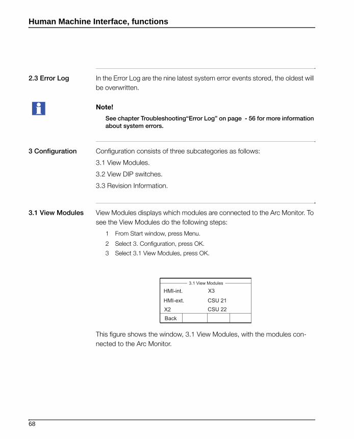
3.1 View Modules View Modules displays which modules are connected to the Arc Monitor. To
see the View Modules do the following steps:
1 From Start window, press Menu.
2 Select 3. Configuration, press OK.
3 Select 3.1 View Modules, press OK.
This figure shows the window, 3.1 View Modules, with the modules con-
nected to the Arc Monitor.
3.1 View Modules
Back
HMI-ext. CSU 21CSU 22X2
X3HMI-int.
68
Human Machine Interface, functions
3.2 View DIP
switches
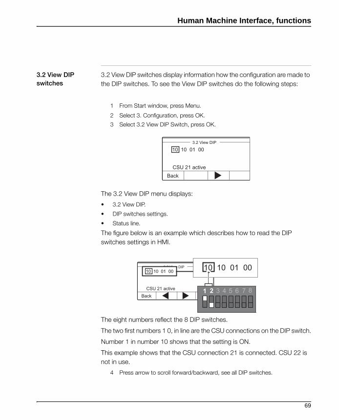
3.2 View DIP switches display information how the configuration are made to
the DIP switches. To see the View DIP switches do the following steps:
1 From Start window, press Menu.
2 Select 3. Configuration, press OK.
3 Select 3.2 View DIP Switch, press OK.
The 3.2 View DIP menu displays:
• 3.2 View DIP.
• DIP switches settings.
• Status line.
The figure below is an example which describes how to read the DIP
switches settings in HMI.
The eight numbers reflect the 8 DIP switches.
The two first numbers 1 0, in line are the CSU connections on the DIP switch.
Number 1 in number 10 shows that the setting is ON.
This example shows that the CSU connection 21 is connected. CSU 22 is
not in use.
4 Press arrow to scroll forward/backward, see all DIP switches.
3.2 View DIP
BackCSU 21 active
10 10 01 00
3.2 View DIP
BackCSU 21 active
10 10 01 00 10 10 01 00
1 2 3 4 5 6 7 8
69
Human Machine Interface, functions
5 Press Back to return to 3. Configuration.
6 Press Back to return to Start window.
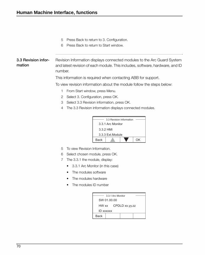
3.3 Revision infor-
mation
Revision Information displays connected modules to the Arc Guard System
and latest revision of each module. This includes, software, hardware, and ID
number.
This information is required when contacting ABB for support.
To view revision information about the module follow the steps below:
1 From Start window, press Menu.
2 Select 3. Configuration, press OK.
3 Select 3.3 Revision information, press OK.
4 The 3.3 Revision information displays connected modules.
5 To view Revision Information.
6 Select chosen module, press OK.
7 The 3.3.1 the module, display:
• 3.3.1 Arc Monitor (in this case)
• The modules software
• The modules hardware
• The modules ID number
3.3 Revision Information
OKBack
3.3.2 HMI3.3.3 Ext.Module
3.3.1 Arc Monitor
3.3.1 Arc Monitor
Back
HW xx CPDLD xx.yy.zzID xxxxxx
SW 01.00.00
70

Human Machine Interface, functions
4 Language If you understand the current menu language, follow the steps to set the
language of the system menu:
In the Main menu:
1 Select 4 Language, press OK.
2 Select the language to use, press OK.Confirm with Yes.
Note!
If you do not understand the menu language, use factory reset.
5 Set Time and
Date
Use this procedure to set the time and date in the system.
In the Set Time menu do the steps below:
1 Scroll to correct hour, press OK.
2 Scroll to correct minutes, press OK.
3 Scroll to correct day, press OK.
4 Scroll to correct month, press OK.
5 Scroll to correct year, press OK to return to Start window.
Factory reset Making the factory reset will force the HMI to start the Start-Up sequence.
Press and hold the 2 soft keys in the middle for more then 10 s.
This will force the HMI to start the Start-Up sequence.
Arc Guard System TVOC-2
Power ErrorTrip
71

Human Machine Interface, functions
72

Technical data
Chapter 8: Technical data
Common technical data
Overvoltage category III
pollution degreee 3
Power supply
Rated operation voltage Ue 100 -250 V DC100-240 V AC 50-60 HZ
Rared insulation voltage Ui 250 V with reinforced insulation
Rated impulse withstand voltage Uimp 4 kV
Output contacts
Contact rated voltage with reinforced insulation between different contacts
Terminals Description Ui Ue Uimp
11, 12, 13 IRF signal 250 V 250 V AC 50-60 HZ, 250 V DC 4 kV
21, 22, 23 Signal relay 250 V 250 V AC 50-60 HZ, 250 V DC 4 kV
31, 32, 34 Signal relay 250 V 250 V AC 50-60 HZ, 250 V DC 4 kV
43, 44 Trip contact 250 V 250 V AC 50-60 HZ, 250 V DC 4 kV
53, 54 Trip contact 250 V 250 V AC 50-60 HZ, 250 V DC 4 kV
63, 64 Trip contact 250 V 250 V AC 50-60 HZ, 250 V DC 4 kV
73, 74 50 V 50 V DC 0.5 kV
Environmental specifications
Permissible ambient temperature in operation - 25 to + 55 °C
Permissible ambient temperature in transportation and storage
- 25 to + 70°C
Humidity Maximum 95%
Altitude 2000 meter above sea level
Degree of protection IP20 Arc MonitorIP54 HMI front side
Safety parameters for application according to IEC61508
Life time 10 years
PFD 3.49 x 10-03
73
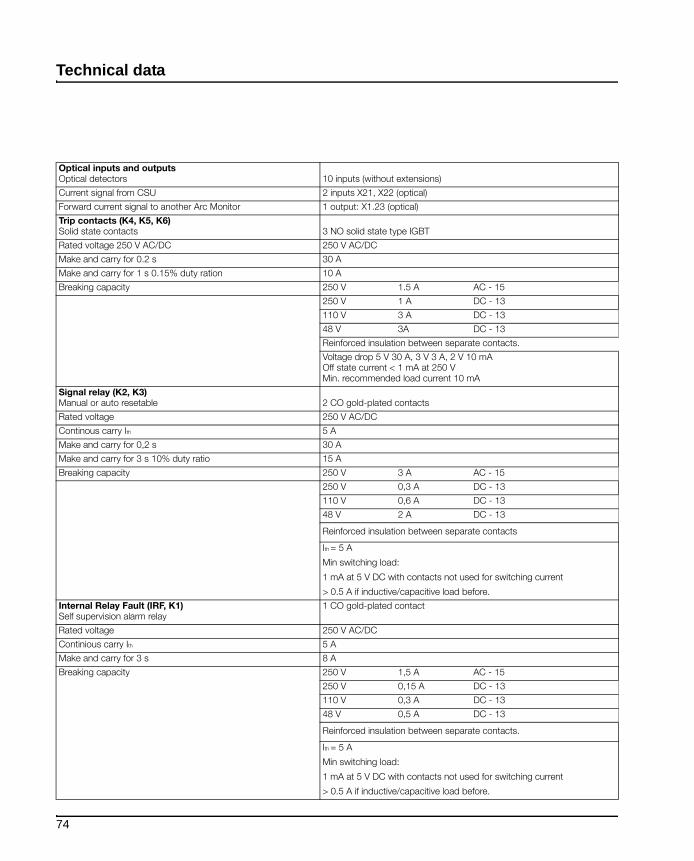
Technical data
Optical inputs and outputsOptical detectors 10 inputs (without extensions)
Current signal from CSU 2 inputs X21, X22 (optical)
Forward current signal to another Arc Monitor 1 output: X1.23 (optical)
Trip contacts (K4, K5, K6)Solid state contacts 3 NO solid state type IGBT
Rated voltage 250 V AC/DC 250 V AC/DC
Make and carry for 0.2 s 30 A
Make and carry for 1 s 0.15% duty ration 10 A
Breaking capacity 250 V 1.5 A AC - 15
250 V 1 A DC - 13
110 V 3 A DC - 13
48 V 3A DC - 13
Reinforced insulation between separate contacts.
Voltage drop 5 V 30 A, 3 V 3 A, 2 V 10 mAOff state current < 1 mA at 250 V Min. recommended load current 10 mA
Signal relay (K2, K3)Manual or auto resetable 2 CO gold-plated contacts
Rated voltage 250 V AC/DC
Continous carry Ith 5 A
Make and carry for 0,2 s 30 A
Make and carry for 3 s 10% duty ratio 15 A
Breaking capacity 250 V 3 A AC - 15
250 V 0,3 A DC - 13
110 V 0,6 A DC - 13
48 V 2 A DC - 13
Reinforced insulation between separate contacts
Ith = 5 A
Min switching load:
1 mA at 5 V DC with contacts not used for switching current
> 0.5 A if inductive/capacitive load before.
Internal Relay Fault (IRF, K1)Self supervision alarm relay
1 CO gold-plated contact
Rated voltage 250 V AC/DC
Continious carry Ith 5 A
Make and carry for 3 s 8 A
Breaking capacity 250 V 1,5 A AC - 15
250 V 0,15 A DC - 13
110 V 0,3 A DC - 13
48 V 0,5 A DC - 13
Reinforced insulation between separate contacts.
Ith = 5 A
Min switching load:
1 mA at 5 V DC with contacts not used for switching current
> 0.5 A if inductive/capacitive load before.
74
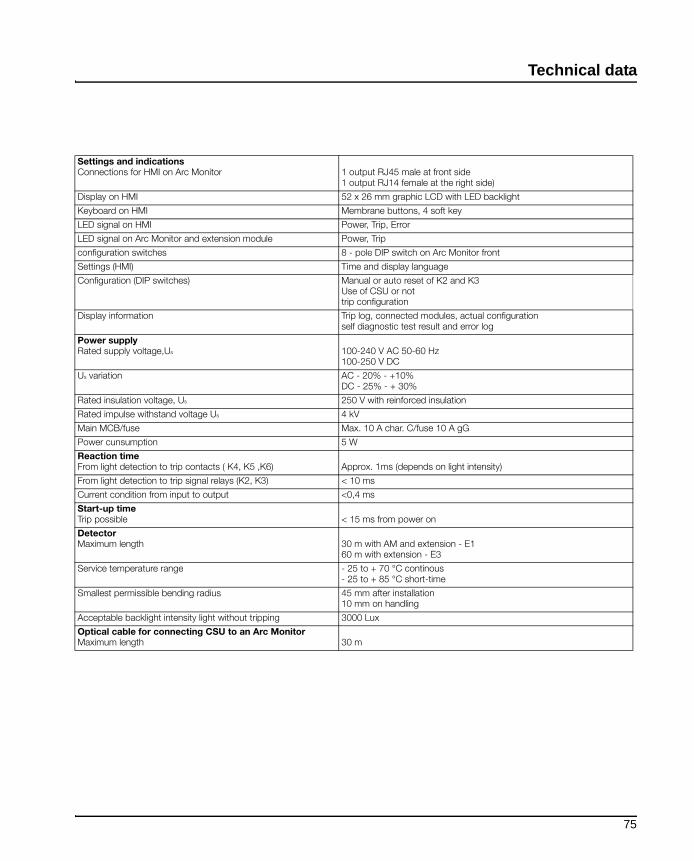
Technical data
Settings and indicationsConnections for HMI on Arc Monitor 1 output RJ45 male at front side
1 output RJ14 female at the right side)
Display on HMI 52 x 26 mm graphic LCD with LED backlight
Keyboard on HMI Membrane buttons, 4 soft key
LED signal on HMI Power, Trip, Error
LED signal on Arc Monitor and extension module Power, Trip
configuration switches 8 - pole DIP switch on Arc Monitor front
Settings (HMI) Time and display language
Configuration (DIP switches) Manual or auto reset of K2 and K3Use of CSU or nottrip configuration
Display information Trip log, connected modules, actual configuration self diagnostic test result and error log
Power supplyRated supply voltage,Us 100-240 V AC 50-60 Hz
100-250 V DC
Us variation AC - 20% - +10%DC - 25% - + 30%
Rated insulation voltage, Us 250 V with reinforced insulation
Rated impulse withstand voltage Us 4 kV
Main MCB/fuse Max. 10 A char. C/fuse 10 A gG
Power cunsumption 5 W
Reaction timeFrom light detection to trip contacts ( K4, K5 ,K6) Approx. 1ms (depends on light intensity)
From light detection to trip signal relays (K2, K3) < 10 ms
Current condition from input to output <0,4 ms
Start-up timeTrip possible < 15 ms from power on
Detector Maximum length 30 m with AM and extension - E1
60 m with extension - E3
Service temperature range - 25 to + 70 °C continous- 25 to + 85 °C short-time
Smallest permissible bending radius 45 mm after installation10 mm on handling
Acceptable backlight intensity light without tripping 3000 Lux
Optical cable for connecting CSU to an Arc MonitorMaximum length 30 m
75

Technical data
Dimensions
Ø5,5
187,5
217
Drilling plan
For M5
230 77
14,749,5 12 x 13,9
38,5
198 177
16,515130
82 M25
Ø25,5
Drilling plan
12
20
Ø10
Ø3
5,8
Ø8
Ø2,2
30,5
Arc Monitor
HMI
Detector with optical cable
76

Technical data
Applications, Diagrams
Example 1: Arc Guard System™ configured to trip all contacts in case of an arc.
SA.1
(K5)
(K4)
Q2
E2N1600A
AVCosWh
3
1
A A400/400 A 400/400 A
6A 250/250 A
10A 250/250 A A 250/250 A
14A 250/160 A A 250/160 A
18A 250/160 A A 250/160 A
22A 250/160 A A 250/160 A
26A 250/160 A A 250/160 A
SA.2
D1
D3
D2
D4
1175/1078
1
6A 250/250 A
10
14
18
22
26
SA.3
1175/1078
Q1
ON
1 2 3 4 5 6 7 8
K4 K5 SA...SA3 Switchgear
K4, K5 Solid state tripping contacts
Q1, Q2, Q3 Circuit-breaker
D1...D4 Detectors
77

Technical data
Example 2: Arc Guard system™ configuredto trip different trip contacts depending on where the arc occurs.
SA.1
Q2E2N1600A Q3
E2N1600A
AVCosWh
3
1
A 400/400 A
6A 250/250 A
10
A 250/250 A
14A 250/160 A
18A 250/160 A
22A 250/160 A
26A 250/160 A
SA.2
1175/1078
A 400/400 A
A 250/250 A
A 250/160 A
A 250/160 A
A 250/160 A
A 250/160 A
1
6A 250/250 A
10
14
18
22
26
SA.3 SA.4
1175/1078
D1
D4
D5 D8
D9
(K4)
(K5) (K6)
Q1
ON
1 2 3 4 5 6 7 8
K4 K6K5 SA...SA4 Switchgear
K4, K5, K6 Solid state tripping contacts
Q1, Q2 Circuit breaker
Q3 Bus couplar
D1...D9 Detectors
78
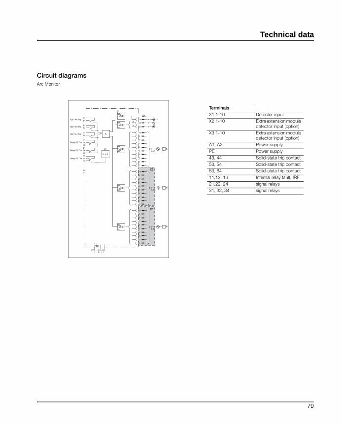
Technical data
Circuit diagramsArc Monitor
236364
5354
4344
31
3234
21
2224
11
1214
7374
B
&
U > 0
A
X1.
X2.
22
21
10
9
8
1-10
IGBT K6 Trip
IGBT K5 Trip
IGBT K4 Trip
Relay K3 Trip
Relay K2 Trip
Relay K1 Trip
7
6
5
4
3
2
1
10
9
8
7
6
5
4
3
2
1
X3.10
9
8
7
6
5
A1PE A2N L1
4
3
2
1
1-10
1-10
Trip
I >
IRF
Terminals
X1 1-10 Detector input
X2 1-10 Extra extension module detector input (option)
X3 1-10 Extra extension module detector input (option)
A1, A2 Power supply
PE Power supply
43, 44 Solid-state trip contact
53, 54 Solid-state trip contact
63, 64 Solid-state trip contact
11,12, 13 Internal relay fault, IRF
21,22, 24 signal relays
31, 32, 34 signal relays
79

Technical data
80

Ordering list
Chapter 9: Ordering list
Description Type Order code
Arc MonitorIncluding one HMI and door mounting accessories
TVOC-2-240 1SFA664001R1001
Extension10 optical inputs
TVOC- 2-E1 1SFA664002R1001
Extension10 optical inputs for 60 meterdetector cable
TVOC- 2- E3 1SFA664002R3001
HMI (Human Machine Interface)additional
TVOC-2-H1 1SFA664002R1005
Detectors
Cable length 1 m TVOC-2-DP1 1SFA664003R1010
Cable length 2 m TVOC-2-DP2 1SFA664003R1020
Cable length 4 m TVOC-2-DP4 1SFA664003R1040
Cable length 6 m TVOC-2-DP6 1SFA664003R1060
Cable length 8 m TVOC-2-DP8 1SFA664003R1080
Cable length 10 m TVOC-2-DP10 1SFA664003R1100
Cable length 15 m TVOC-2-DP15 1SFA664003R1150
Cable length 20 m TVOC-2-DP20 1SFA664003R1200
Cable length 25 m TVOC-2-DP25 1SFA664003R1250
Cable length 30 m TVOC-2-DP30 1SFA664003R1300
Cable length 60 m TVOC-2-DP60 1SFA664003R3600 '(3)
Remarks:(3) Only to be used with TVOC-2-E3
Arc Monitor
Extension
HMI
Detector
81
Ordering list
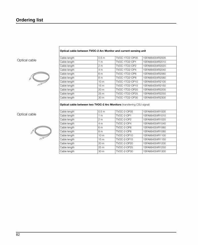
Optical cable between TVOC-2 Arc Monitor and current sensing unit
Cable length 0.5 m TVOC-1TO2-OP05 1SFA664004R2005
Cable length 1 m TVOC-1TO2-OP1 1SFA664004R2010
Cable length 2 m TVOC-1TO2-OP2 1SFA664004R2020
Cable length 4 m TVOC-1TO2-OP4 1SFA664004R2040
Cable length 6 m TVOC-1TO2-OP6 1SFA664004R2060
Cable length 8 m TVOC-1TO2-OP8 1SFA664004R2080
Cable length 10 m TVOC-1TO2-OP10 1SFA664004R2100
Cable length 15 m TVOC-1TO2-OP15 1SFA664004R2150
Cable length 20 m TVOC-1TO2-OP20 1SFA664004R2200
Cable length 25 m TVOC-1TO2-OP25 1SFA664004R2250
Cable length 30 m TVOC-1TO2-OP30 1SFA664004R2300
Optical cable between two TVOC-2 Arc Monitors (transferring CSU signal)
Cable length 0.5 m TVOC-2-OP05 1SFA664004R1005
Cable length 1 m TVOC-2-OP1 1SFA664004R1010
Cable length 2 m TVOC-2-OP2 1SFA664004R1020
Cable length 4 m TVOC-2-OP4 1SFA664004R1040
Cable length 6 m TVOC-2-OP6 1SFA664004R1060
Cable length 8 m TVOC-2-OP8 1SFA664004R1080
Cable length 10 m TVOC-2-OP10 1SFA664004R1100
Cable length 15 m TVOC-2-OP15 1SFA664004R1150
Cable length 20 m TVOC-2-OP20 1SFA664004R1200
Cable length 25 m TVOC-2-OP25 1SFA664004R1250
Cable length 30 m TVOC-2-OP30 1SFA664004R1300
Optical cable
Optical cable
82
Index
AAdd/Remove module from the Arc Monitor 46Applicable safety standards 10Arc Monitor 17Arc Monitor functions 15Available languages 48
BBreaker trip 40
CChecking DIP Switches 49Checking power on Arc Monitor 45Checking the trip log 65Circuit diagrams 79Configuration 68Configurations 39Connecting CSU cable 34Connecting optical detectors 32Controlling 51Current Sensing Unit input 18Current Sensing Unit output 18Current Sensing Unit(option) 43Current Sensing Unit, CSU inputs 17Current Sensing Unit, CSU, output 17
DDetector (option) 17Detector Inputs 18Detector inputs 17Detectors 19Diagnostics 55, 65Diagrams 77Dimensions 76DIP switch 17, 18DIP switches 39
EError event 55
Extension 20Extension (option) 17Extension unit plug in area 17External HMI connection 18
FFactory reset 71Final confirmation 50
GGetting started 23
HHandling Error log 55Handling the Arc Monitor 13HMI Display 63HMI external connection 17HMI menu structure 63HMI start menu 63Human Machine Interface, HMI 17
IInstallation 21Installation procedure 21Intermediate storage 23IRF 19
KK2 and K3 19
LLanguage 71LED signals 62Limitation of liability 14List of contents 23
MMaintenance 53Manual/Auto reset configuration 42Menu and languages 65Mount the Arc Monitor on a DIN rail 25Mount the Arc Monitor on the wall 25Mounting 24Mounting and connecting the Arc Monitor to the system 22Mounting Arc Monitor 24Mounting on a DIN rail 25Mounting on wall 25Mounting the HMI 26Mounting the Optical detector 27
NNo CSU connected 43
OOne (1) CSU connected 44Ordering list 81Overview of Arc Monitor 16
PPerform Diagnostics 66Placing Arc Monitor 24Power on to the Arc Monitor 45Power supply 17
RReceiving and checking 23Revision information 70
SSafety 9Safety signs 12Set Time ans date 71Signal Relays 19Soft keys 63Solid state tripping contacts 17, 19Storage 14System Status 66

TTesting the installation 51Tools required 22Trip Log 64Trip notification window 64Trouble shooting 55Troubleshooting 55Two (2) CSU connected 44
VView DIP switches 69View Modules 68
WWork in safety manner 13


Contact us
ABB AB
Cewe-Control
SE-721 61 VÄSTERÅS, Sweden
Telephone +46 21 32 07 00
Telefax +46 21 12 60 01
www.abb.com/lowvoltage
©C
op
yrig
ht
20
10, A
ll rig
ht
rese
rved
. S
pecifi
catio
n s
ub
changew
ithoutn
Inst
ruct1
SFC
170
011M
0201
, M
arc
h 2
01
0 P
rod
AB
B A
B,
Cew
e-C
ontr
ol/X
M