Embed Size (px)
Citation preview
This document is the property of Disseny Electrònic Integral S.L. Its reproduction in part or in full is prohibited.
Page 1-1
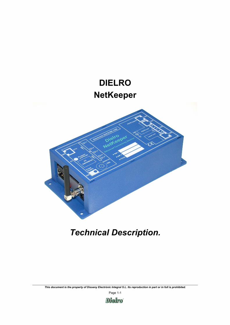
DIELRO NetKeeper
Technical Description.

This document is the property of Disseny Electrònic Integral S.L. Its reproduction in part or in full is prohibited.
Page 2-2
TABLE OF CONTENTS 1. Introduction................................................................................................................................................................. 3 2. WHAT NetKeeper CAN OFFER: ................................................................................................................................. 3 3. Description.................................................................................................................................................................. 4 4. FEATURES................................................................................................................................................................. 4
4.1 GSM...................................................................................................................................................................... 4 4.2 Landlines............................................................................................................................................................... 4 4.3 SMS ...................................................................................................................................................................... 4 4.4 Serial port.............................................................................................................................................................. 4 4.5 Ethernet................................................................................................................................................................. 4 4.6 Internal line............................................................................................................................................................ 5
5. POWER SUPPLY SYSTEMS ..................................................................................................................................... 5 6. OPERATION............................................................................................................................................................... 6
6.1 Voice call operation mode ..................................................................................................................................... 6 6.2 Settings assessed to estimate available and stand-alone operation....................................................................... 6
6.2.1 Concerning each GSM network (each SIM):.................................................................................................... 6 6.2.2 Concerning hardware: ..................................................................................................................................... 7
6.3 Events log ............................................................................................................................................................. 7 6.3.1 Concerning the GSM module: ......................................................................................................................... 7 6.3.2 Concerning Ethernet: ...................................................................................................................................... 7 6.3.3 Concerning the PSTN: .................................................................................................................................... 7 6.3.4 Concerning device power supply:.................................................................................................................... 8 6.3.5 Concerning the serial port: .............................................................................................................................. 9
6.4 Programming and control ...................................................................................................................................... 9 6.5 Remote analyser ................................................................................................................................................... 9
7. CONNECTION.......................................................................................................................................................... 10 8. NETKEEPER Technical Specifications ..................................................................................................................... 11
8.1 GENERAL........................................................................................................................................................... 11 8.2 GSM INTERFACE............................................................................................................................................... 11 8.3 OTHER IMPORTANT FEATURES ...................................................................................................................... 11 8.4 TELEPHONE INTERFACES ............................................................................................................................... 12 8.5 ETHERNET INTERFACE.................................................................................................................................... 12 8.6 POWER SUPPLY................................................................................................................................................ 12 8.7 ENVIRONMENTAL CONDITIONS....................................................................................................................... 12 8.8 DIMENSIONS AND PRESENTATION................................................................................................................. 12

This document is the property of Disseny Electrònic Integral S.L. Its reproduction in part or in full is prohibited.
Page 3-3
1. INTRODUCTION
Dielro NetKeeper is a product specifically designed for security and fire-fighting installations.
All technical aspects have been meticulously analysed during development, with the aim of creating a system with the utmost quality and reliability regarding secure data transmission and concerning emergency power supply.
Its superb performance, combined with its compact form and the fact that it is easy to install and program, along with a highly-efficient after-sales service, make NetKeeper one of the most secure and reliable devices on the market.
The use of a set of copper wires, in other words, a basic (PSTN) telephone line together with (x)DSL, is likely in many cases to result in false alarms, due to the cable being disconnected from the switchboard. Even using 2 different lines.
On the other hand, where transmitters are used which incorporate GSM/GPRS and a landline (PSTN), isolating the alarm system is relatively straightforward. For instance, an inhibitor may cut off radio coverage to the system, and cut off the line, making it impossible for any calls to be made.
NetKeeper is a technologically advanced system incorporating 3 networks (TCP/IP, PSTN and GSM/GPRS) simultaneously, such that a fault in any of them is checked in a matter of seconds, and at no time does the system become ineffective.
2. WHAT NETKEEPER CAN OFFER: NetKeeper combines an innovative design with compact dimensions (194 x 93.6 x 54.3mm.), as well as high performance, thereby complying with all telecommunications, electro-magnetic compatibility and electrical safety standards: Our device features:
Up to 2 GSM/GPRS operators at the same time.
(x)DSL - TCP/IP Connection.
PSTN Connection.
Smart back-up supply management.
Analysis of a large number of settings.
NetKeeper may be used by security companies as an interface for transmitting warnings given by the installation alarm switchboard to the receiver exchange via the TCP/IP protocol, or as a transmitter. All the while, with the guarantee that it will perform monitoring of the 3 networks.
NetKeeper can also meet the needs of the client and can be used in tandem with any device specified by the receiver exchange without affecting its operation. Dielro NetKeeper can transmit the information from any installation to the software at the security company premises, in order for it to be processed on an independent computer managing incidents and logging all events that arise.

This document is the property of Disseny Electrònic Integral S.L. Its reproduction in part or in full is prohibited.
Page 4-4
3. DESCRIPTION NetKeeper is a technologically advanced system which incorporates and monitors 3 networks (TCP/IP, PSTN and GSM/GPRS) at the same time, such that a fault in any of them is checked in a matter of seconds.
One or two of the networks could fail, but it is practically impossible for the 3 networks to simultaneously fail. Also, it should be borne in mind that the system can incorporate up to 2 different GSM operators, meaning that loss of coverage by both, together with breakage of the copper wires would only be likely where tampering were involved.
The control algorithm implemented by the Dielro NetKeeper system is distinguished by its high level of security. For this reason, in the event of all the networks going down, we can be sure that a break-in is taking place.
In addition, it provides a redundant telephone connection via the public switched telephone network (PSTN), with the possibility of automatically selecting the GSM and PSTN networks. It also provides a POTS (internal line) interface compatible with the full range of Dielro devices and with any DTMF telephone.
The device uses TRP (Transmitted Relay Process) technology, which makes it possible to connect multiple devices on its internal line using a single telephone line, without the need for additional buses and power supplies, just the set of telephones itself, covering distances of several hundred metres between devices with a simple yet secure connection.
It can be configured locally or remotely
It also enables two-way voice communication, initiated from the actual device or remotely from any telephone.
Remote operating is assisted by a voice interface, which simplifies operation with the device. In manual mode, the telephone’s own DTMF keypad is used to communicate with it, although it is possible to use a PC running Dielro software for more extensive control.
It can also act as a traditional GSM link with most telephones and private telephone exchanges.
4. FEATURES
4.1 GSM Dielro NetKeeper is compatible with GSM networks: EGSM900 and EGSM1800
The system allows the dynamic use of up to 2 SIM cards from the same or different providers. The card(s) is/are accessed from the outside, without the need to open the device.
It has a dual-band external aerial attached. The AE200-SM accessory, an external aerial with 2m of cable, can be used where coverage is low.
4.2 Landlines Interface with analogue PSTN network (external line: compatible with TBR-21 and most European providers.
POTS internal line) interface, compatible with Dielro devices D-103, D-102, etc., and with DTMF tone telephones
4.3 SMS It is capable of sending and receiving SMS messages, by means of which it regularly receives information regarding available balance, battery status, level of coverage, activation/deactivation of Outputs and checking the status of Inputs and Outputs, etc.
It acknowledges received messages and attempts to re-send messages not received by the intended recipient and which consequently have timed out.
4.4 Serial port It has a dedicated serial port for device add-ons: input and/or output process, generating of internal buses (Wifi, RS485, EIB, CAN, USB ...), domotics, etc. By way of this NetKeeper interface, it is possible to cater for most available alarm systems.
4.5 Ethernet It has an Ethernet connection with a built-in web server:
TCP, UDP, DHCP, SNMP, SSL/TSL, Telnet, Rlogin, RFC2217, LPD, http/HTTPS, SMTP, ICMP, IGMP, ARP
This document is the property of Disseny Electrònic Integral S.L. Its reproduction in part or in full is prohibited.
Page 5-5
IP addresses are assigned universally (static, DHCP, Auto-IP).
Encryption of data via SSL V3.0/TSL V1.0 (DES, 3DES, AES).
Warning of certain events via email.
4.6 Internal line. Routing of calls by number dialled. It enables different operations to be carried out depending on the number dialled:
• Calling via PSTN.
• Calling via GSM (SIM1).
• Calling via GSM (SIM2).
• Calling via any GSM.
• Sending an SMS. (device tracking,....)
• Routing of data by Ethernet.
• Sending an email.
• Carrying out a specific operation via the serial port.
• Registering the operation as an event.
• Blocking the call.
• Programming the device (once authorised having entered an access code).
• Call diverting.
• Identification of incoming calls in accordance with specific telephony standards.
• Identification of incoming calls by voice.
One or more of the specified options can be carried out at the same time.
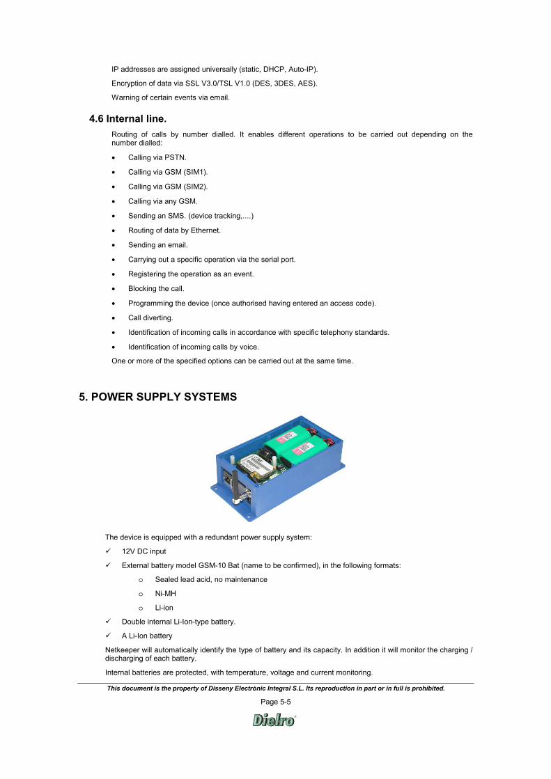
5. POWER SUPPLY SYSTEMS
The device is equipped with a redundant power supply system:
12V DC input
External battery model GSM-10 Bat (name to be confirmed), in the following formats:
o Sealed lead acid, no maintenance
o Ni-MH
o Li-ion
Double internal Li-Ion-type battery.
A Li-Ion battery
Netkeeper will automatically identify the type of battery and its capacity. In addition it will monitor the charging / discharging of each battery.
Internal batteries are protected, with temperature, voltage and current monitoring.
This document is the property of Disseny Electrònic Integral S.L. Its reproduction in part or in full is prohibited.
Page 6-6
It is fitted with an additional temperature probe for monitoring available capacity in the event of a power failure. They are also fitted with a thermostat-regulated heater to extend their operating range.
Important: Only use batteries supplied by Dielro,
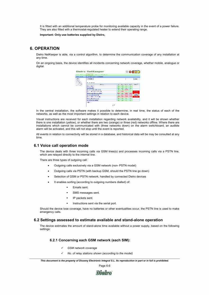
6. OPERATION Dielro NetKeeper is able, via a control algorithm, to determine the communication coverage of any installation at any time.
On an ongoing basis, the device identifies all incidents concerning network coverage, whether mobile, analogue or digital.
In the central installation, the software makes it possible to determine, in real time, the status of each of the networks, as well as the most important settings in relation to each device.
Visual instructions are received for each installation regarding network availability, and it will be shown whether there is one installation (yellow), or whether there are two (orange) or three (red) networks offline. Where there are installations which cannot be communicated with (three networks down) on the alarm switchboard, an audible alarm will be activated, and this will not stop until the event is reported.
All events in relation to connectivity will be stored in a database, and historical data will be may be consulted at any time.
6.1 Voice call operation mode The device deals with three incoming calls via GSM lines(s) and processes incoming calls via a PSTN line, which are relayed directly to the internal line.
There are three types of outgoing call:
• Outgoing calls exclusively via a GSM network (non- PSTN model)
• Outgoing calls via PSTN (with backup GSM, should the PSTN line go down)
• Selection of GSM or PSTN network, handled by connected Dielro devices
• It enables sorting (according to outgoing numbers dialled) of:
Emails sent.
SMS messages sent.
IP packets sent.
Instructions sent via the serial port.
Should the device lose coverage, have no batteries or other eventualities occur, the PSTN line is used to make emergency calls.
6.2 Settings assessed to estimate available and stand-alone operation The device estimates the amount of stand-alone time available without a power supply, based on the following settings:
6.2.1 Concerning each GSM network (each SIM):
GSM network coverage
No. of relay stations shown (according to the model)
This document is the property of Disseny Electrònic Integral S.L. Its reproduction in part or in full is prohibited.
Page 7-7
No. of providers available
Balance on the SIM card(s) in the case of pay as you go.
Level of coverage
Coverage statistics
6.2.2 Concerning hardware:
Initial battery capacity and charge status
No. of charge / discharge cycles accumulated
The battery’s capacity history.
Battery temperature
Average power used (dependent on coverage)
6.3 Events log NetKeeper enables the following events to be logged:
6.3.1 Concerning the GSM module:
Balance low (less than an hour’s talk time) for each of the SIMs where pay as you go.
No balance remaining on either of the SIM cards.
Recovery of the balance on each of the SIM cards.
Critical coverage on each of the SIM cards.
No coverage on either of the SIM cards.
Sufficient coverage on each of the SIM cards.
Tracking and logging of the progress of coverage.
Consecutive faults in the logging of each of the SIM cards.
No SIM activated.
Recovery of activated SIM.
GSM module out of service.
GSM module operational.
External events to be defined received via SMS.
External events to be defined received via modem.
External events to be defined received via GSM (voice mode).
Others.
6.3.2 Concerning Ethernet:
Ethernet network outage.
Recovery of the Ethernet network.
Uninterrupted communication reception failure (Watchdog).
Recovery of uninterrupted communication.
Ethernet module out of service.
Ethernet module operational.
External events to be defined received via Ethernet.
6.3.3 Concerning the PSTN:
No PSTN line found.
This document is the property of Disseny Electrònic Integral S.L. Its reproduction in part or in full is prohibited.
Page 8-8
Recovery of the PSTN line.
No internal line found.
Recovery of the internal line.
Specific incoming call.
Specific outgoing call.
Incoming call log.
Outgoing call log.
6.3.4 Concerning device power supply:
Maximum charge temperature exceeded.
Minimum charge temperature exceeded.
Maximum discharge temperature exceeded.
Minimum discharge temperature exceeded.
Start of overload battery 1.
End of overload battery 1.
Start of overload battery 2.
End of overload battery 2.
Network failure.
Recovery of the network.
Start battery 1 discharged.
End battery 1 discharged.
Start battery 2 discharged.
End battery 2 discharged.
Start battery 1 low.
End battery 2 low.
Start battery 1 not detected.
Start battery 1 detected.
Start battery 2 not detected.
Start battery 2 detected.
Logging and tracking of the temperature progress of the batteries.
Start charge battery 1.
Start charge battery 2.
End charge battery 1.
End charge battery 2.
Start discharge battery 1.
Start discharge battery 2.
End discharge battery 1.
End discharge battery 2.
Start heating with electricity network.
End heating with electricity network.
Start heating without electricity network.
End heating without electricity network.

This document is the property of Disseny Electrònic Integral S.L. Its reproduction in part or in full is prohibited.
Page 9-9
6.3.5 Concerning the serial port:
Information on devices connected to the serial port.
External events, to be defined, received from the serial port.
Serial port out of service.
Serial port operational.
Optionally, it is possible to give instructions for a call to be made to a target telephone when a certain event occurs. The device checks the date and time of each event occurring. Communication may be made via a GSM call (conventional or modem) or an acknowledgement SMS message.
The events table may be consulted at any time via conventional GSM, GPRS modem, PSTN or Ethernet.
6.4 Programming and control The device may be programmed and controlled locally or remotely, via a range of methods:
Remotely: via Ethernet, SMS, GPRS modem, DTMF tones (calling GSM) or Dielro IT application.
Locally: Directly from the internal line connector via a tone-dial telephone. If it is an installation with other devices Dielro, from the programming connector of any of them.
There is also a voice message facility, with standard or user-customised messages for monitoring and manually programming the device. Messages can be customised via: GPRS modem, GSM line or internal line.
Programming and monitoring of the equipment are password-protected.
NOTE. Dielro has a customer support service for responding to any query regarding use or programming of our products.
6.5 Remote analyser The device makes it possible to consult the main settings of the PSTN line and GSM network in real time:
• PSTN:
⋅ Line analysis ⋅ Ring analysis ⋅ Monitoring of the audio signal (call progress, line busy, talk tones).
• GSM:
⋅ Level of signal received ⋅ Coverage statistics ⋅ No. of relay stations shown (according to GSM model) ⋅ Available providers (according to GSM model), ⋅ SIM card balance.
Measurements made with the aforementioned analyser are transmitted to a remote receiver connected to a PC application which shows the data gathered in real time.
This document is the property of Disseny Electrònic Integral S.L. Its reproduction in part or in full is prohibited.
Page 10-10
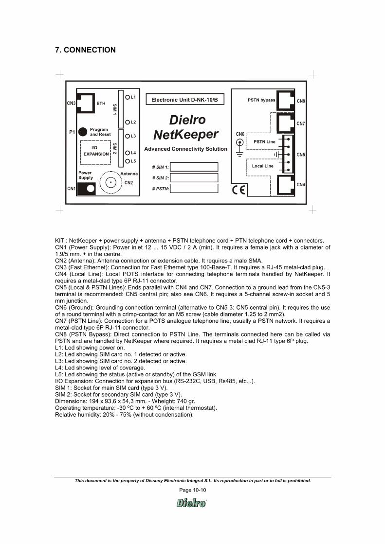
7. CONNECTION
Dielro NetKeeper
PSTN Line
Electronic Unit D-NK-10/B
Advanced Connectivity Solution
P1
SIM 1
SIM 2
Programand Reset
Antenna
Local Line
# SIM 2:
# PSTN:
# SIM 1:PowerSupply
ETHL1
L5
L4
L3
L2
I/O
PSTN bypass
EXPANSION
KIT : NetKeeper + power supply + antenna + PSTN telephone cord + PTN telephone cord + connectors. CN1 (Power Supply): Power inlet 12 ... 15 VDC / 2 A (min). It requires a female jack with a diameter of 1.9/5 mm. + in the centre. CN2 (Antenna): Antenna connection or extension cable. It requires a male SMA. CN3 (Fast Ethernet): Connection for Fast Ethernet type 100-Base-T. It requires a RJ-45 metal-clad plug. CN4 (Local Line): Local POTS interface for connecting telephone terminals handled by NetKeeper. It requires a metal-clad type 6P RJ-11 connector. CN5 (Local & PSTN Lines): Ends parallel with CN4 and CN7. Connection to a ground lead from the CN5-3 terminal is recommended: CN5 central pin; also see CN6. It requires a 5-channel screw-in socket and 5 mm junction. CN6 (Ground): Grounding connection terminal (alternative to CN5-3: CN5 central pin). It requires the use of a round terminal with a crimp-contact for an M5 screw (cable diameter 1.25 to 2 mm2). CN7 (PSTN Line): Connection for a POTS analogue telephone line, usually a PSTN network. It requires a metal-clad type 6P RJ-11 connector. CN8 (PSTN Bypass): Direct connection to PSTN Line. The terminals connected here can be called via PSTN and are handled by NetKeeper where required. It requires a metal clad RJ-11 type 6P plug. L1: Led showing power on. L2: Led showing SIM card no. 1 detected or active. L3: Led showing SIM card no. 2 detected or active. L4: Led showing level of coverage. L5: Led showing the status (active or standby) of the GSM link. I/O Expansion: Connection for expansion bus (RS-232C, USB, Rs485, etc...). SIM 1: Socket for main SIM card (type 3 V). SIM 2: Socket for secondary SIM card (type 3 V). Dimensions: 194 x 93,6 x 54,3 mm. - Wheight: 740 gr. Operating temperature: -30 ºC to + 60 ºC (internal thermostat). Relative humidity: 20% - 75% (without condensation).
This document is the property of Disseny Electrònic Integral S.L. Its reproduction in part or in full is prohibited.
Page 11-11
8. NETKEEPER TECHNICAL SPECIFICATIONS
8.1 GENERAL Redundant Conectivity: Quadruple redundancy: TCP/IP, GSM, PSTN, Serial Port I/O Man- machine Interface: Voice assisted and hearing aid Very High Reliability: Permanent supervision of batteries, TCP/IP, PSTN, PTN and Serial Port Redundant batteries: 2 x 1,5 hour each1 Compact System: Case includes batteries, antenna, I/O and TCP/IP WEB server Rugged design: Shielded case, with protected telephone interfaces & ground connection CE marked: True fulfilment of current Directives that apply on European market
8.2 GSM INTERFACE Frequency bands: Dual-Band GSM 900 & E-GSM 900, and GSM 1800 Automatic hand-over between GSM 900 and GSM 1800 bands E-GSM 900 & GSM 900 Frequencies: TX 880-890 MHz, RX 925-935 MHz @ E-GSM 900 TX 880-915 MHz, RX 935-960 MHz @ GSM 900 RF power: Maximum 2W (33 dBm), Power Class 4 GSM 1800 Frequencies: TX 1710-1785 MHz, RX 1805-1880 MHz RF power: Maximum 1W (30 dBm), Power Class 1 Receiver sensitivity: -102 dBm GSM antenna: SMA plug-female 50 Ω (dual band omnidirect. 0 dB antenna, incl.) Voice calls: Cellular Terminal able to use with standard telephone terminals Improved echo cancellation for hands-free Speech codecs: FR (Full Rate), EFR2 (Enhanced Full Rate) and HR (Half Rate) Data spcecs: GPRS Class B (4+1 down/up link) CSD at 9600 bps HSCSD (2+1 down/up link) SMS (MO, MT and CBM) for remote management and supervision SIM Cards: Small plug-in card 3V type, with external push & push sockets Two SIM sockets (able to manage different network providers)
8.3 OTHER IMPORTANT FEATURES Security and reliability: Permanent supervision of: TCP/IP, GSM coverage, physical integrity of PTN cabling, PSTN availability and Serial Port I/O GSM RF field strength and coverage history and statistics SIM credit information in prepaid mode Advanced Batteries supervision and management by means µP Redundant Li-ion battery & extended speech time: > 2 hour Operation: Expansion bus for data communication and I/O EMI protection with shielded case (able to work with near antennas) Several remote/local programming ways (SMS, DTMF, modem,…) with voice aid
1 Typical value speaking. 2 Provided that EFR is available in the network

This document is the property of Disseny Electrònic Integral S.L. Its reproduction in part or in full is prohibited.
Page 12-12
8.4 TELEPHONE INTERFACES General: High quality telephone line interfaces Voice and Data Digital Signal Processing Intelligent PSTN bypassing for rest of equipments Line impedance: selectable among several complex values CLI (Calling Line Identification). ETSI DTMF, V.23 and Bellcore PTN (Local Line): POTS interface (compatible with TBR-21 terminals) Especially designed for Dielro equipments and TRP technology Off-hook loop current: 25 mA On-hook voltage: 25 V Loop resistance: < 600 Ω Ring voltage: 50 Vrms (>25 Vrms @ 6 TE’s LF=100 acc. EG 201 188) Ring load: REN>10 (more than 10 telephone devices acc. EN 300 001) Call control signalling: polarity reversal and flashing PSTN line: Backup line for redundant connexion Rugged line with common & differential mode protections Compatible w/ TBR-21 and most of European landline telephone providers
8.5 ETHERNET INTERFACE
Fast Ethernet: 8-wire RJ-45: 10/100 Base-T (ISO 8877) Web Server with secured protocols Protocols: TCP/IP, DHCP, SNMP, SSL/TSL, HTTP, HTTPS, SMTP, UDP, SMTP optional) IP addresses: Static, Auto-IP, DHCP Encryption (Security Features): SSL V 3.0 / TSL V1.0 DES, 3DES, AES (128-, 192-, or 256-bits key depth)
8.6 POWER SUPPLY External Power Supply: 12 V DC / 2 A Internal Batteries: 2 x Li-Ion Battery Pack 7,4 V / 2200 mAh
8.7 ENVIRONMENTAL CONDITIONS Operating Temperature: -10 ºC to +60 ºC Extended Temper. Range: -30 ºC to +60 ºC (w/ mains)(internally thermostated) Operating Humidity: 20 – 75 % Storage Temperature: - 40ºC to +60 ºC (-40 ºC to +85 ºC w/o battery cells) Storage Humidity: 5 – 95 % (w/o condensation)
8.8 DIMENSIONS AND PRESENTATION Kit: NetKeeper (w/ batteries), power supply, internal antenna, telephone cable, telephone lines and ground connector Size: 194,0(W)x93,6(D)x54,3(H) w/o antenna