Embed Size (px)
Citation preview
Technical Short Description
IEC 61491, EN 61491 SERCOS interfaceThe internationally-standardized digitalinterface for communication between
controllers and drives in numerically-controlled machines

2
3
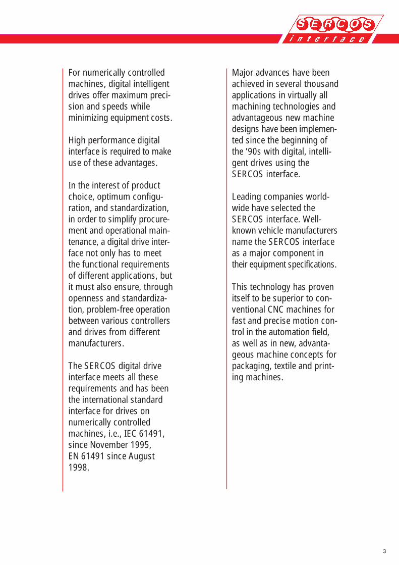
For numerically controlledmachines, digital intelligentdrives offer maximum preci-sion and speeds whileminimizing equipment costs.
High performance digitalinterface is required to makeuse of these advantages.
In the interest of productchoice, optimum configu-ration, and standardization,in order to simplify procure-ment and operational main-tenance, a digital drive inter-face not only has to meetthe functional requirementsof different applications, butit must also ensure, throughopenness and standardiza-tion, problem-free operationbetween various controllersand drives from differentmanufacturers.
The SERCOS digital driveinterface meets all theserequirements and has beenthe international standardinterface for drives onnumerically controlledmachines, i.e., IEC 61491,since November 1995,EN 61491 since August1998.
Major advances have beenachieved in several thousandapplications in virtually allmachining technologies andadvantageous new machinedesigns have been implemen-ted since the beginning ofthe ’90s with digital, intelli-gent drives using theSERCOS interface.
Leading companies world-wide have selected theSERCOS interface. Well-known vehicle manufacturersname the SERCOS interfaceas a major component intheir equipment specifications.
This technology has provenitself to be superior to con-ventional CNC machines forfast and precise motion con-trol in the automation field,as well as in new, advanta-geous machine concepts forpackaging, textile and print-ing machines.
4
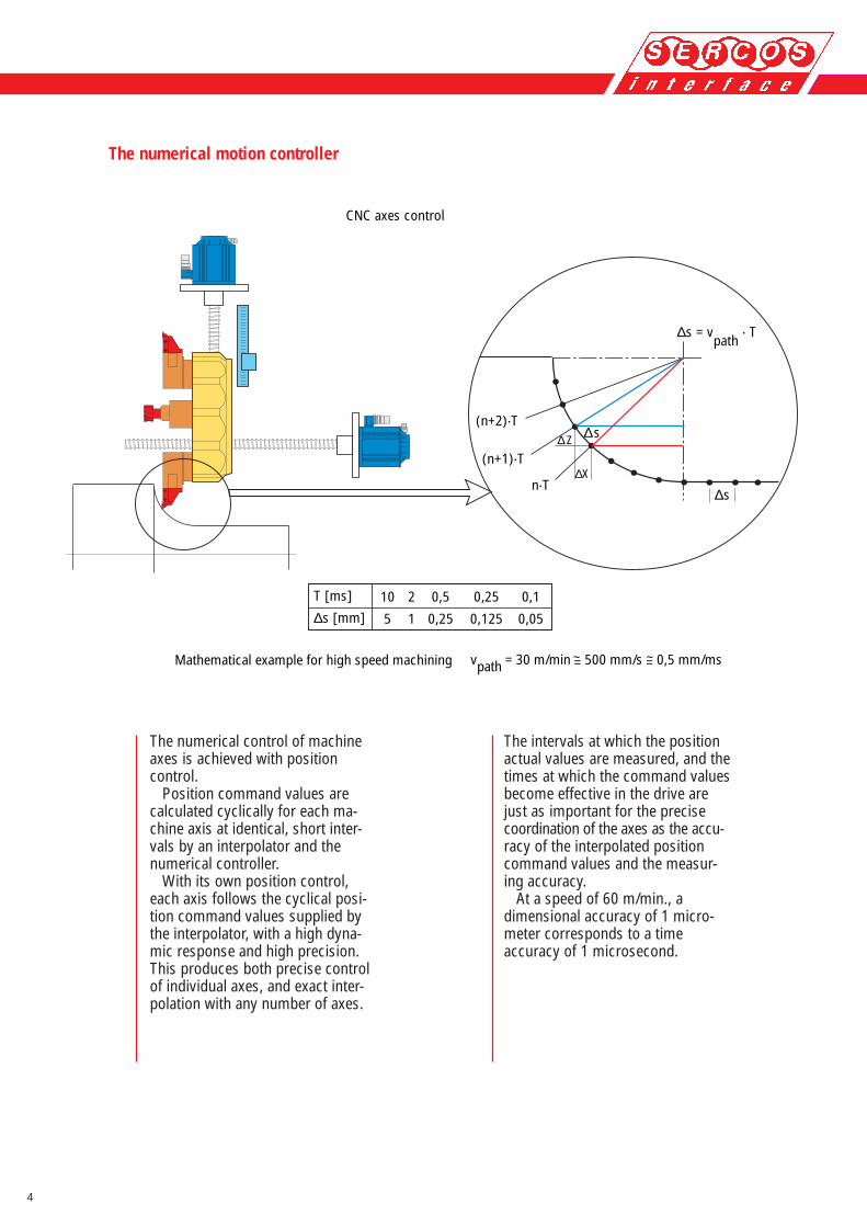
The intervals at which the positionactual values are measured, and thetimes at which the command valuesbecome effective in the drive arejust as important for the precisecoordination of the axes as the accu-racy of the interpolated positioncommand values and the measur-ing accuracy.
At a speed of 60 m/min., adimensional accuracy of 1 micro-meter corresponds to a timeaccuracy of 1 microsecond.
The numerical motion controller
The numerical control of machineaxes is achieved with positioncontrol.
Position command values arecalculated cyclically for each ma-chine axis at identical, short inter-vals by an interpolator and thenumerical controller.
With its own position control,each axis follows the cyclical posi-tion command values supplied bythe interpolator, with a high dyna-mic response and high precision.This produces both precise controlof individual axes, and exact inter-polation with any number of axes.
Mathematical example for high speed machining
CNC axes control
∆s = vpath
. T
~vpath = 30 m/min = 500 mm/s = 0,5 mm/ms
∆s
∆s∆Z
∆X
(n+2).T
(n+1).T
n.T
T [ms]
∆s [mm]10
5
2
1
0,5
0,25
0,25
0,125
0,1
0,05
~
5
X–
+ W
IKv
AD
U
X
M3~
X
Numerical control unit(position control)
AC servo drive controller(velocity control)
AC servomotor
Velocitycontroller
PWMtorque control
Torque feedback
Monitoring
Velocitycommand
value
Position feedback value
Velocity feedback value
Torquecommand value
Feedback
Positionencoder
Commutation
Rotor position
analogue± 10 V
Positioninterface
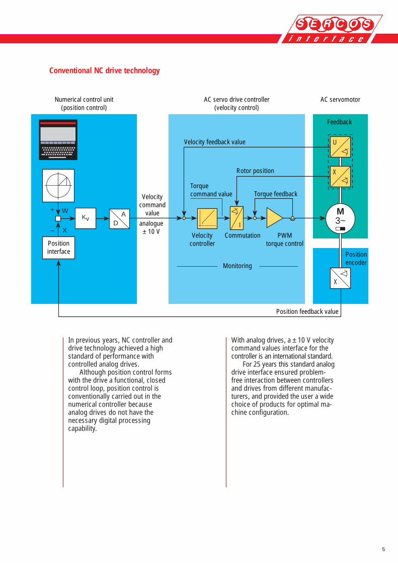
In previous years, NC controller anddrive technology achieved a highstandard of performance withcontrolled analog drives.
Although position control formswith the drive a functional, closedcontrol loop, position control isconventionally carried out in thenumerical controller becauseanalog drives do not have thenecessary digital processingcapability.
With analog drives, a ± 10 V velocitycommand values interface for thecontroller is an international standard.
For 25 years this standard analogdrive interface ensured problem-free interaction between controllersand drives from different manufac-turers, and provided the user a widechoice of products for optimal ma-chine configuration.
Conventional NC drive technology
6
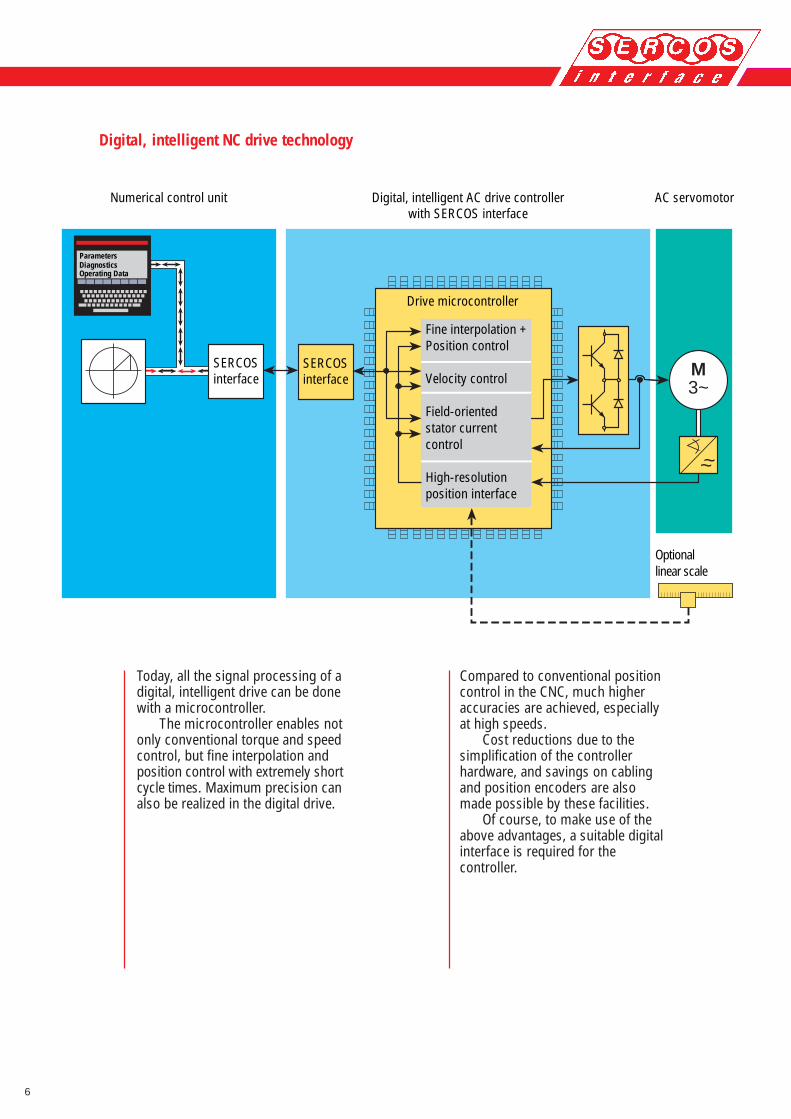
Today, all the signal processing of adigital, intelligent drive can be donewith a microcontroller.
The microcontroller enables notonly conventional torque and speedcontrol, but fine interpolation andposition control with extremely shortcycle times. Maximum precision canalso be realized in the digital drive.
M3~
~~
Digital, intelligent AC drive controllerwith SERCOS interface
AC servomotorNumerical control unit
Drive microcontroller
Fine interpolation +Position control
Velocity control
Field-orientedstator currentcontrol
High-resolutionposition interface
SERCOSinterface
SERCOSinterface
DiagnosticsOperating Data
Parameters
Optionallinear scale
Compared to conventional positioncontrol in the CNC, much higheraccuracies are achieved, especiallyat high speeds.
Cost reductions due to thesimplification of the controllerhardware, and savings on cablingand position encoders are alsomade possible by these facilities.
Of course, to make use of theabove advantages, a suitable digitalinterface is required for thecontroller.
Digital, intelligent NC drive technology
7
Parameterization and diagnostics viacontroller terminals
Digital drives are matched to dif-ferent applications and controllersby parameters.
Digital drives permit the drive’sinternal data and diagnostic signalsto be output and displayed.
Suitable display and input facil-ities on the digital controller areabsolutely necessary since simplechecks and adjustments, as withanalog drives, are virtually impossible.
The SERCOS interface enablesinternal drive data, parameters anddiagnostics to be displayed, input,and saved via NC controller termi-nals, a service channel and astandardized service data routine.
Transmission rates
SERCOS interface offers followingtransmission rates: 2, 4, 8 and16 MBit/s.
Real-time requirements of a digitaldrive interface
With conventional NC drive techno-logy using the ± 10 V interface,there were no real-time problemsbetween the controller and thedrives. The analog command valuesare always processed immediatelyby the continually operating analogdrives.
Digital transmission of commandvalues and actual values
Digital drives operate cyclically. Ineach interpolation cycle of thecontroller, all command values andactual-values have to be updated inall drives.
The SERCOS interface offerscyclical exchange of commandvalues and actual values for alldrives with a selectable cycle timeof 62 µs, 125 µs, 250 µs and everywhole multiple of 250 µs up to 65 ms.
Synchronization
The digital drive interface mustprovide synchronization betweenthe cyclic controller and the equallycyclic digital drives. The synchroni-zation must have microsecondaccuracy since precise coordinationof the drives is only guaranteed ifthe actual values are measured atexactly the same time in all digitaldrives and all command valuesbecome effective simultaneously.
The SERCOS interface offerssynchronization with microsecondaccuracy for any number of digitaldrives.
8
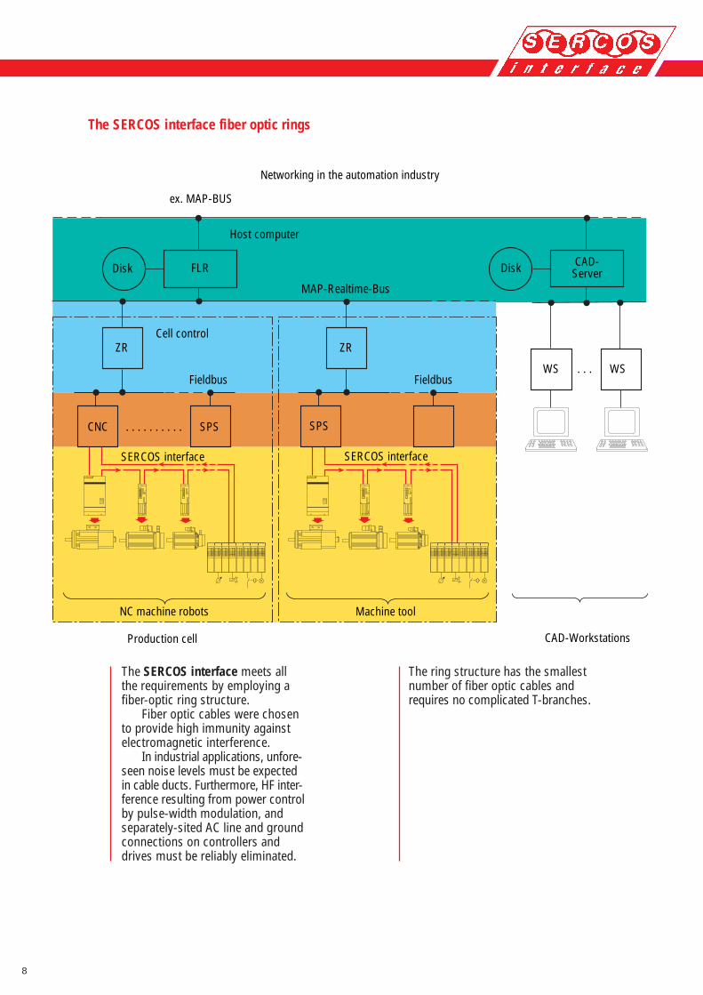
The ring structure has the smallestnumber of fiber optic cables andrequires no complicated T-branches.
The SERCOS interface meets allthe requirements by employing afiber-optic ring structure.
Fiber optic cables were chosento provide high immunity againstelectromagnetic interference.
In industrial applications, unfore-seen noise levels must be expectedin cable ducts. Furthermore, HF inter-ference resulting from power controlby pulse-width modulation, andseparately-sited AC line and groundconnections on controllers anddrives must be reliably eliminated.
Networking in the automation industry
Host computer
MAP-Realtime-Bus
Cell control
Production cell
NC machine robots
Fieldbus Fieldbus
Machine tool
CAD-Workstations
SERCOS interface SERCOS interface
CAD-Server
ex. MAP-BUS
ZR
Disk DiskFLR
ZR
SPS CNC . . . . . . . . . . SPS
WS . . . WS
The SERCOS interface fiber optic rings
9
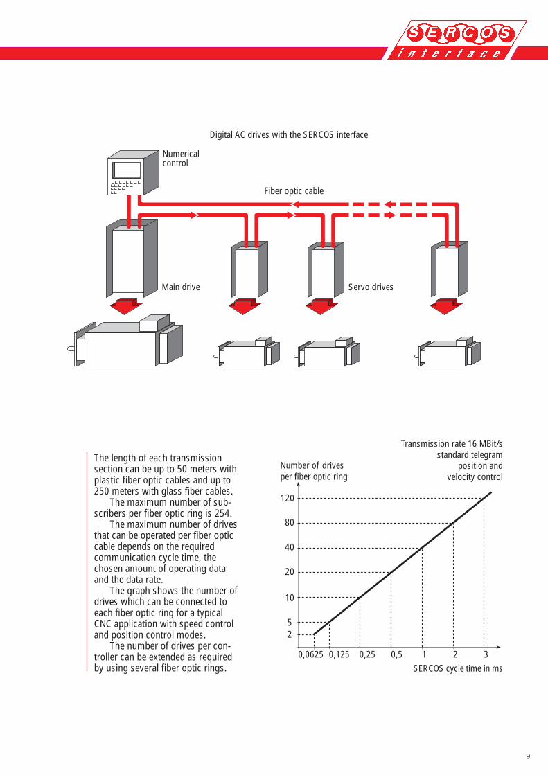
The length of each transmissionsection can be up to 50 meters withplastic fiber optic cables and up to250 meters with glass fiber cables.
The maximum number of sub-scribers per fiber optic ring is 254.
The maximum number of drivesthat can be operated per fiber opticcable depends on the requiredcommunication cycle time, thechosen amount of operating dataand the data rate.
The graph shows the number ofdrives which can be connected toeach fiber optic ring for a typicalCNC application with speed controland position control modes.
The number of drives per con-troller can be extended as requiredby using several fiber optic rings.
310,250,1250,0625
25
10
40
120
80
20,5
20
Numericalcontrol
Main drive Servo drives
Fiber optic cable
Digital AC drives with the SERCOS interface
Number of drivesper fiber optic ring
SERCOS cycle time in ms
Transmission rate 16 MBit/sstandard telegram
position andvelocity control
10
#1 #2 #5
#1 #2 #5
#1 #2 #5
#1 #2 #5
0 0
00
1000710 960
500/60050/150
a )
b )
c )
d )Master´sData
Master´sData
Master´sData
M a s t e r d a t a F r a m e
Data#5
S y n c - F r a m e
F i r s t D r i v e ´ s D a t a F r a m e
Data#1
MasterDrives
MasterDrives
MasterDrives
MasterDrives
L a s t D r i v e ´ s D a t a F r a m e
MASTER
MASTER
MASTER
Sync! Sync! Sync!
MASTER
30 µs t/µs t/µs
t/µst/µs
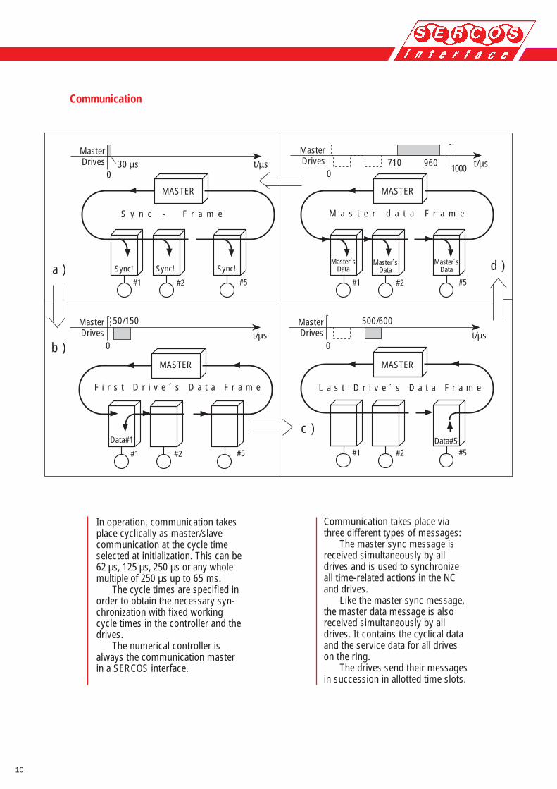
Communication takes place viathree different types of messages:
The master sync message isreceived simultaneously by alldrives and is used to synchronizeall time-related actions in the NCand drives.
Like the master sync message,the master data message is alsoreceived simultaneously by alldrives. It contains the cyclical dataand the service data for all driveson the ring.
The drives send their messagesin succession in allotted time slots.
Communication
In operation, communication takesplace cyclically as master/slavecommunication at the cycle timeselected at initialization. This can be62 µs, 125 µs, 250 µs or any wholemultiple of 250 µs up to 65 ms.
The cycle times are specified inorder to obtain the necessary syn-chronization with fixed workingcycle times in the controller and thedrives.
The numerical controller isalways the communication masterin a SERCOS interface.

11
a)
b)
c)
d)
...
Telegr.delimiter
Addr. Data fieldFramechecksequence
Telegr.delimiter
Master Data telegr. Drive Telegr.
Data recordDrive.u Ma.
Data recordMa. Drive.z
Data recordMa. Drive.x
Master Sync.-Telegr.
Ringstatus1 byte
fixed structure configurable structure
Control/status2-byte
Serviceinfo
2, 4, 6 or 8-byte
configurable data fieldinitialized by the selected preconfigurated telegram
Data recordMa. Drive.y
The configurability of the real-timedata allows any other operatingmodes to be used independently.
Service data is exchanged only atthe request of the master. Servicedata is transmitted with ahandshaking procedure in 2, 4, 6 or8-byte portions in the service infofield and then reassembled at thereceiver.
NRZI-coded HDLC protocols areused for communication.
In each communication cycle, thereal-time data is transmitted inthe so-called configurable datafield.
At initialization, the identifi-cation number system specifieswhich real-time data is trans-mitted. Apart from numerical datasuch as command values and actual-values, these can also be bit listswith I/O instructions.
Priority messages with specificreal-time data have been specifiedfor the three basic operating modes- torque control,velocity control andposition control - as well ascombined velocity/position control.
Message structure

12
Standardized data
1
6
1
11
01
2 3
45
6
78
90
1
2 3
45
6
78
9
IDN S-0-0122
IDN S-0-0165
IDN S-0-0121IDN S-0-0118
IDN S-0-0115
IDN S-0-0166
IDN S-0-0116 IDN S-0-0123
IDN S-0-0049 IDN S-0-0050
IDN S-0-0041IDN S-0-0042IDN S-0-0054IDN S-0-0147IDN S-0-0151
Slide
Position control Velocity control Torque control
Feedback type Motor feedback Motor feedback Motor shaft
Following error with without
ScalingtypeUnit(linear)
Command/actual value(data length)
Linear feedback
with without
Explanation
preferredparameter
Drive operation modes
fiber
opt
ic ri
ng
------- -------
0,000 1 mm ; 0,000 001 inchyes
0,001 mm/min ; 0,000 01 inch/minyes
1,0 N ; 0,1lbfyes
mm ; inch mm/s ; mm/mininch/s ; inch/min
N (Newton)lbf (pound-force)
32 Bit 32 Bit 16 Bit
CNC
SERCOSinterface
Standardization of communicationmethods is not enough. Controllerand drive interoperability can onlybe guaranteed if the type of databeing exchanged is also standardized.
Over 400 data blocks and the effectof commands were specified in theSERCOS interface to ensure thatproducts from different manufac-turers work with each other.
13
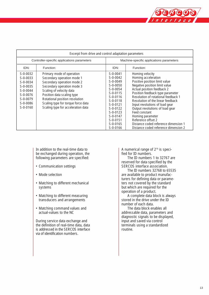
In addition to the real-time data tobe exchanged during operation, thefollowing parameters are specified:
• Communication settings
• Mode selection
• Matching to different mechanicalsystems
• Matching to different measuringtransducers and arrangements
• Matching command values andactual-values to the NC
During service data exchange andthe definition of real-time data, datais addressed in the SERCOS interfacevia of identification numbers.
A numerical range of 216 is speci-fied for ID numbers.
The ID numbers 1 to 32767 arereserved for data specified by theSERCOS interface association.
The ID numbers 32768 to 65535are available to product manufac-turers for defining data or parame-ters not covered by the standardbut which are required for theoperation of a product.
A complete data block is alwaysstored in the drive under the IDnumber of each data.
The data block enables alladdressable data, parameters anddiagnostic signals to be displayed,input and saved via controlterminals using a standardizedroutine.
Excerpt from drive and control adaptation parameters
IDN:
Homing velocityHoming accelerationPositive position limit valueNegative position limit valueActual position feedback 2Position feedback type parameterResolution of rotational feedback 1Resolution of the linear feedbackInput revolutions of load gearOutput revolutions of load gearFeed constantHoming parameterReference offset 2Distance coded reference dimension 1Distance coded reference dimension 2
S-0-0041S-0-0042S-0-0049S-0-0050S-0-0054S-0-0115S-0-0116S-0-0118S-0-0121S-0-0122S-0-0123S-0-0147S-0-0151S-0-0165S-0-0166
Function:
Controller-specific applications parameters Machine-specific applications parameters
IDN: Function:
Primary mode of operationSecondary operation mode 1Secondary operation mode 2Secondary operation mode 3Scaling of velocity dataPosition data scaling typeRotational position resolutionScaling type for torque force dataScaling type for acceleration data
S-0-0032S-0-0033S-0-0034S-0-0035S-0-0044S-0-0076S-0-0079S-0-0086S-0-0160
14
System safety with the SERCOSinterface
Digital, intelligent drives with theSERCOS interface provideoutstanding protection againstuncontrolled drive movements andexcessive velocities.
The drives’ internal intelligenceprovides perfect self-monitoring withthe aid of the position values,command values, actual values anddrive parameters, combined withforced shutdown in the event of amal-function or failure of the driveprocessor.
Furthermore, excessive axisvelocities or run-away due to faultyor incorrectly transmitted positioncommand values can be completelyeliminated by logical monitoring inthe drive processor of the commandvalues received by the controller.
Safety redundancy is achievedby monitoring the actual value datafed back to the controller via theSERCOS interface.
Even in the event of a commu-nication failure, safe shutdown ofthe drives is ensured by the drive’sinternal monitoring and also bymonitoring at the controller inconjunction with a higher-orderemergency-stop circuit.
Block-by-block operation
The SERCOS specification alsoincludes block-by-block operationfor operating digital, intelligentdrives with PLC controllers and asauxiliary axes.
I/O functions
The SERCOS interface is designednot only as a digital drive interface,but also as a fast I/O bus with abuilt-in service channel. An additio-nal specification - "SERCOS I/Ofunctions" - is available for thisapplication.
Detection and handling ofcommunication errors
In the SERCOS interface,communication errors are detectedwith high reliability by the HDLCprotocol and additional monitoringof the known message lengths andthe known transmission times. TheHamming distance is greater than 4.
Errors in the transmission ofservice data (parameters and diag-nostic signals) are corrected via ahandshaking procedure. Erroneousdata is retransmitted.
Real-time data (command valuesand actual values) is corrected auto-matically by updating in each com-munication cycle. In the case ofcommunication errors, the last validcommand values are used until thenext cycle.
The drives are stopped in theevent of two successive erroneoustransmissions.
15
Available services and products
The SERCOS Interface Association(IGS) was founded in 1990 with theaim of launching the SERCOSinterface worldwide and supportingpotential users.
SERCOS N.A. with its head office inBloomingdale, Illinois, is a usergroup of American companies,started in 1993.
SERCOS Japan with a head officein Tokyo, Japan, is a user group ofJapanese companies, started in1998.
The right to carry the SERCOSinterface marking on products isgranted by the IGS after testing thecharacteristics laid down in theSERCOS specification.
Conformity checks on SERCOSinterface products are carried outby ISW, University of Stuttgart(Germany) under authorizationof IGS.
User support and tools for thedevelopment, testing andinstallation of SERCOS interfaceproducts are offered by severalsuppliers and the IGS.
An overview of the services andproducts currently available isobtainable from the IGS under thetitle "A brief overview of productsequipped with the SERCOSinterface".
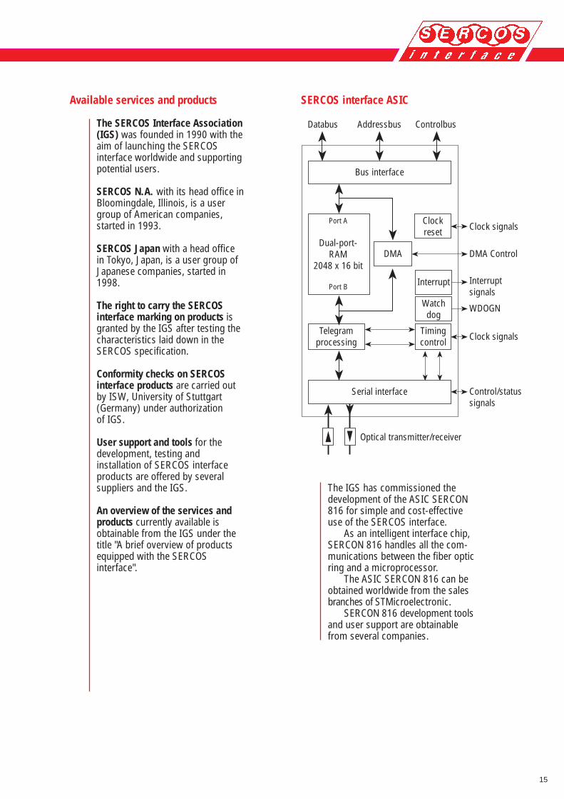
SERCOS interface ASIC
The IGS has commissioned thedevelopment of the ASIC SERCON816 for simple and cost-effectiveuse of the SERCOS interface.
As an intelligent interface chip,SERCON 816 handles all the com-munications between the fiber opticring and a microprocessor.
The ASIC SERCON 816 can beobtained worldwide from the salesbranches of STMicroelectronic.
SERCON 816 development toolsand user support are obtainablefrom several companies.
Databus Addressbus Controlbus
Bus interface
Clockreset
Interrupt
Port A
Dual-port-RAM
2048 x 16 bit
Port B
DMA
Telegramprocessing
Timingcontrol
Clock signals
DMA Control
Interruptsignals
Control/statussignals
Clock signals
Optical transmitter/receiver
Serial interface
Watchdog
WDOGN

16
SERCOS interface for controllers
SERCANS and DRIVETOP providesimple and high-performance useof the SERCOS interface withcontrollers.
SERCANS is a complete, opera-tional add-on module which enablesdigital, intelligent drives with SERCOSinterface to be used with CNCs, PCsand VME bus controllers.
SERCANS automatically handles allcommunication, synchronizationand error recovery between thecontroller and the digital, intelligentdrives.
NC-Programexecution
Diagnostics
Interpolation
Synchro-nization Synchronization
Diagnostics channel
MMI Service channel
User interfaceDRIVETOP
SERCANS
Actual value channel
Command value channel
Command channel
NC Service channel
Control unitor PC
Inte
rfac
e fo
r mic
ropr
oces
sor,
PC o
r VM
E-bu
s
SERCOS fiber optic ring
ParametersDiagnosticsOperating Data
for each axis
17
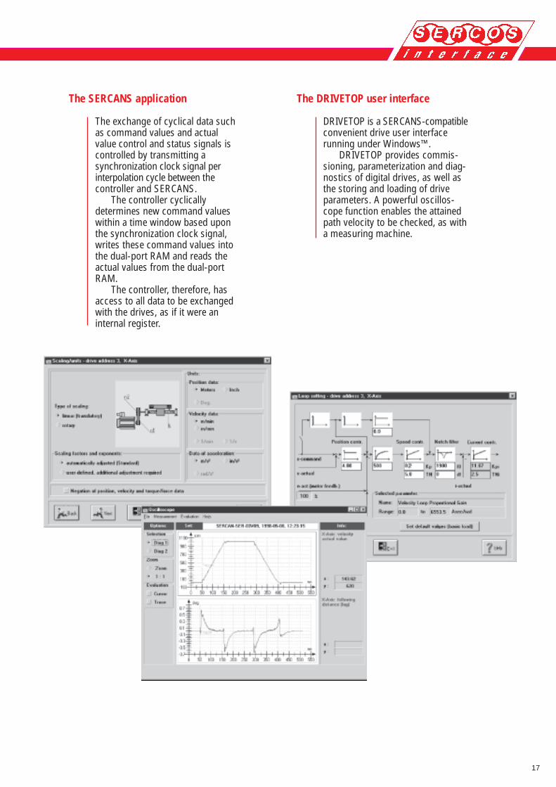
The DRIVETOP user interface
DRIVETOP is a SERCANS-compatibleconvenient drive user interfacerunning under Windows™.
DRIVETOP provides commis-sioning, parameterization and diag-nostics of digital drives, as well asthe storing and loading of driveparameters. A powerful oscillos-cope function enables the attainedpath velocity to be checked, as witha measuring machine.
The SERCANS application
The exchange of cyclical data suchas command values and actualvalue control and status signals iscontrolled by transmitting asynchronization clock signal perinterpolation cycle between thecontroller and SERCANS.
The controller cyclicallydetermines new command valueswithin a time window based uponthe synchronization clock signal,writes these command values intothe dual-port RAM and reads theactual values from the dual-portRAM.
The controller, therefore, hasaccess to all data to be exchangedwith the drives, as if it were aninternal register.

18
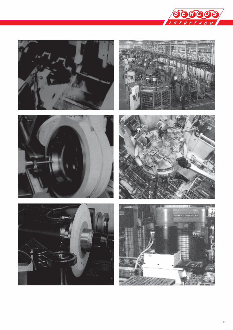
SERCOS interface applications
Advances have been achieved inseveral thousand applications invirtually all machining technologiesand advantageous new machinedesigns have been implementedsince the start of the ’90s withdigital, intelligent drives using theSERCOS interface.
The range of applications includes:
• Turning and complete machining
• Free-form milling, including HSC
• Machining centres, including HSC
• Crankshaft orbital grinding
• Cam profile grinding
• Tool grinding machines
• Precision gear cutting
• Transfer lines
• Rotary transfer tables
• Assembly lines
• Assembly robots
19
20
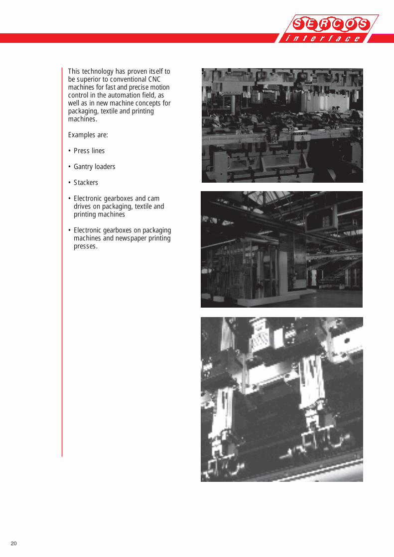
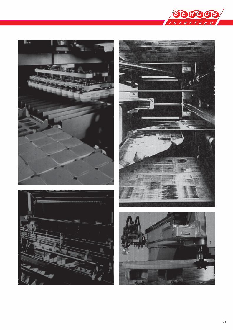
This technology has proven itself tobe superior to conventional CNCmachines for fast and precise motioncontrol in the automation field, aswell as in new machine concepts forpackaging, textile and printingmachines.
Examples are:
• Press lines
• Gantry loaders
• Stackers
• Electronic gearboxes and camdrives on packaging, textile andprinting machines
• Electronic gearboxes on packagingmachines and newspaper printingpresses.
21

Interest GroupSERCOS interface e. V.
Landhausstrasse 20D-70190 Stuttgart
Tel. +49 (0)711/28457-50Fax +49 (0)711/28457-55
E-Mail: [email protected]://www.sercos.de
2.002 E/02.02 - A4 - © IGS - Reprint not allowed! All rights reserved! Printed in Federal Republic of Germany
USA:SERCOS N. A.
attn. Mr. Ronald M. Larsen2871 Brisbane Drive
USA - Lake in the Hills, IL 60156 Tel. 0001 / 847/961-6858
Fax 001 / 847/ 961 - 6638E-Mail: [email protected]
http://www.sercos.com
Japan:SERCOS Japan
Nikkei Digital Engineeringattn. Mr. Hideki Haraguchi
2-7-6 Hirakawa-cho, Chiyoda-kuTokyo, 102-0093 Japan
Tel. +81-3-5210-4457Fax +81-3-5210-4458
E-Mail: [email protected]://www.sercos.or.jp