Embed Size (px)
Citation preview
1
Design Verification at D2Audio Design Verification at D2Audio March 8, 2006Mayur Mehta
2
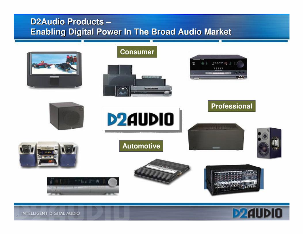
D2Audio ProductsD2Audio Products
• D2Audio builds all Digital Class D amplifier controller ICs which use sophisticated digital Pulse Width Modulation (PWM) Techniques. � All-digital signal path� On-Chip DSP provides amplifier controls and
comprehensive audio signal processing.� 25-600 watts per channel� 93% power efficient
3
D2Audio Products –Enabling Digital Power In The Broad Audio MarketD2Audio Products –Enabling Digital Power In The Broad Audio Market
Consumer
Automotive
Professional
4
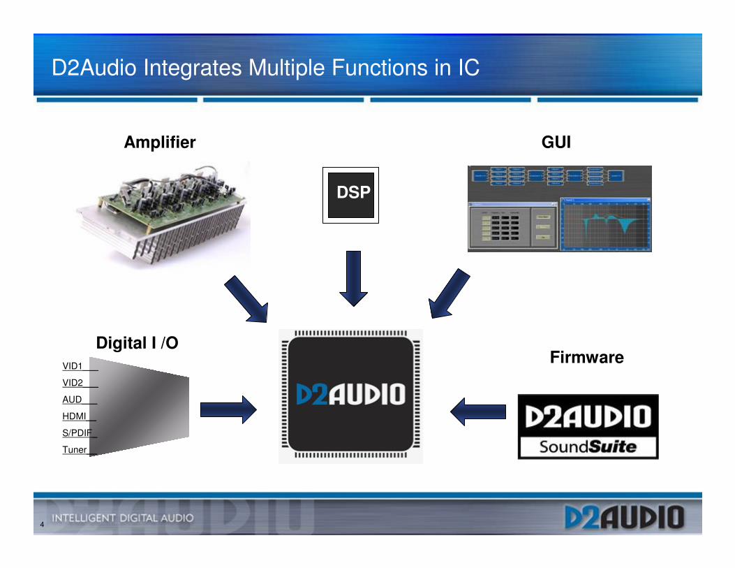
GUI
D2Audio Integrates Multiple Functions in IC
Digital I /OVID1___
VID2___
AUD___
HDMI__
S/PDIF_
Tuner__
Firmware
DSP
Amplifier
5
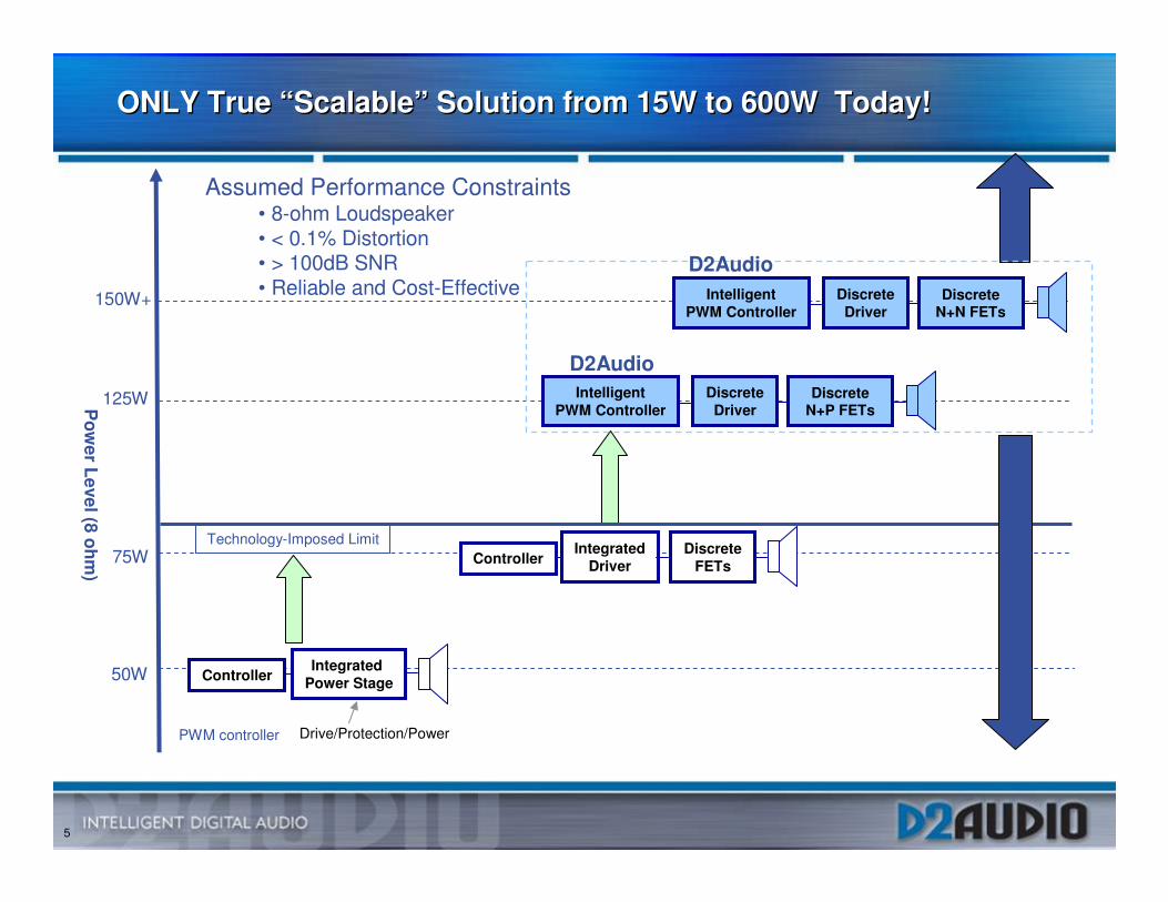
ONLY True “Scalable” Solution from 15W to 600W Today!ONLY True “Scalable” Solution from 15W to 600W Today!
50W
75W
PWM controller Drive/Protection/Power
ControllerIntegrated
DriverDiscrete
FETs
Pow
er Level (8 ohm)
DiscreteDriver
IntelligentPWM Controller
Discrete N+P FETs
ControllerIntegrated
Power Stage
125W
DiscreteDriver
IntelligentPWM Controller
Discrete N+N FETs
150W+
Technology-Imposed Limit
Assumed Performance Constraints• 8-ohm Loudspeaker• < 0.1% Distortion• > 100dB SNR• Reliable and Cost-Effective
D2Audio
D2Audio
• 40V Process Limit • Protection• Control• Drive
6
Verification OverviewVerification Overview
7
Chips DevelopedChips Developed
• 1st Gen Digital Audio Engine IC (DAE-1)� PWM Controller with SRC (Sample Rate Converter), DSP, Output
Protection � In production for > 1year
• Demonstrated full audio performance and features on first silicon.
• 2nd Gen Digital Audio Engine IC (DAE-2)� First to develop Class D amplifier with all-digital feedback
• Power supply feed-forward and closed-loop feedback technology correct for power supply variations, non-linearity and other distortion-inducing mechanisms
• As much as 60dB performance improvement• Most analog PWM Solutions use analog closed-loop feedback
� In Production Now• Demonstrated full audio performance with feed forward and feedback on first
silicon• 4 channel and 7 channel reference design solutions
8
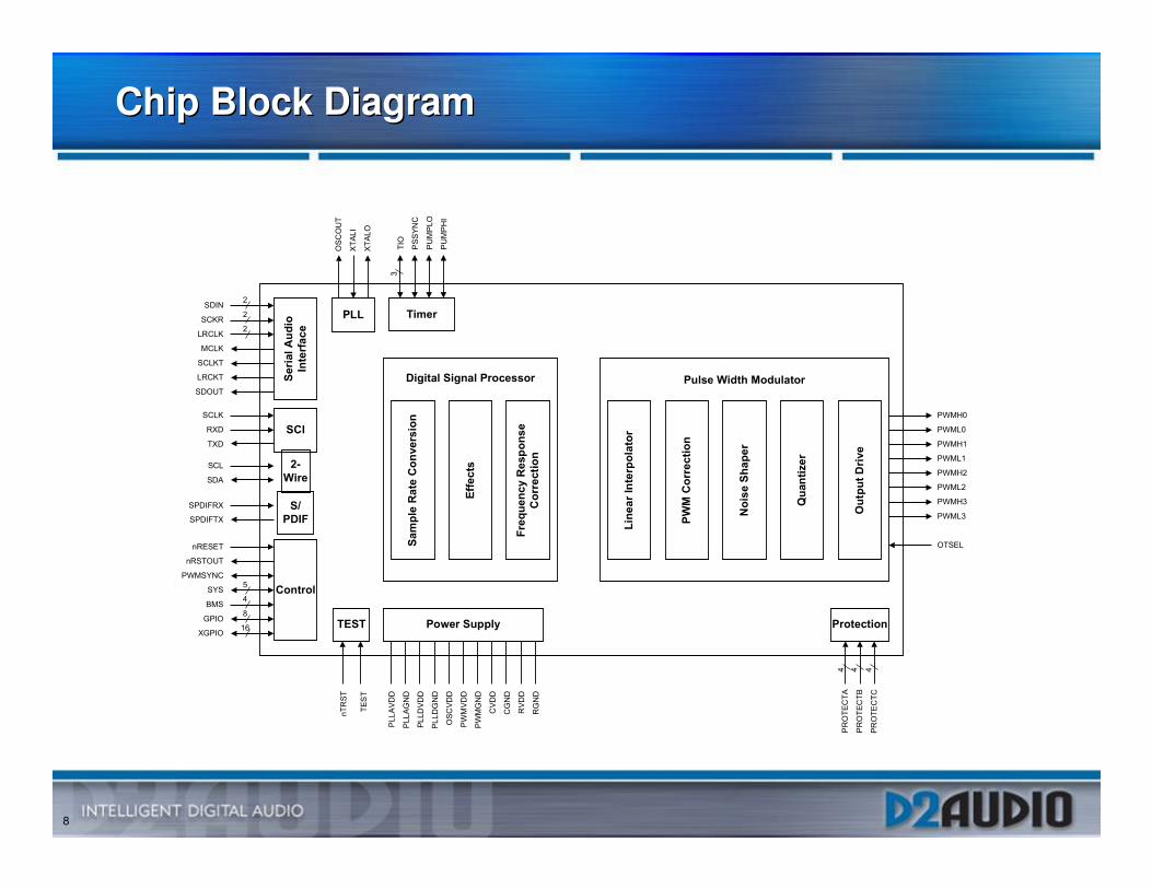
Chip Block DiagramChip Block Diagram
���������
����
���� ������
������ ��
����
���
��
���
����
���
��� �
�
�
�
������
�����
���� �
�������
���
���
����
�����
��
����
��
���
��
����
������
�������
����
�
�
��
�
���
���� �
����
����
�����
���
������
� ���
� ����
������
�����
�����
�����
������
������
������
����
����
���
���
�� �� ��� � ������!!��
� ���" ������#��!���
������!
���$������"�!��!�
����������
����������
�������
�������
�������
��
����
���
�����
����
�����
����
�����
����
����
����
���� �������� ���
��%�����������
&��!���' ��
(� ���)��
*��������#�
��!������'�%��� ���
�
���
���
��
���
9
Verification TechniquesVerification Techniques
• C++ Model• Verilog simulations
� Block-level and chip-level verification� NC-Verilog, Verdi and SureCov� CVS, Bugzilla and nLint� Verilog level transactors interacting with embedded C Program to
synchronize DSP and I/O functions� Assembly level and C code to perform DSP functions
• FPGA emulation� Full chip implementation synthesized to Xilinx FPGA� Custom I/O boards developed for “rest of system”� Connectivity to real world audio streams� Back-end power electronics for amplifier system testing
10
Development and Verification Flow for Signal Processing BlocksDevelopment and Verification Flow for Signal Processing Blocks
• Matlab – Numerical Analysis tool to aid in developing algorithms
• C++ based simulator
• Matlab script generates a setup file and input data files� Executes the C++ simulator and dumps output into files.
� On termination of simulator, Matlab script performs analysis of the data produced by simulator.
• C++ model to implement algorithms on a fairly high level � Verify the functionality using the above C++ simulator
� Determine gross computational complexity
• Refine the algorithms to a cycle accurate level
11
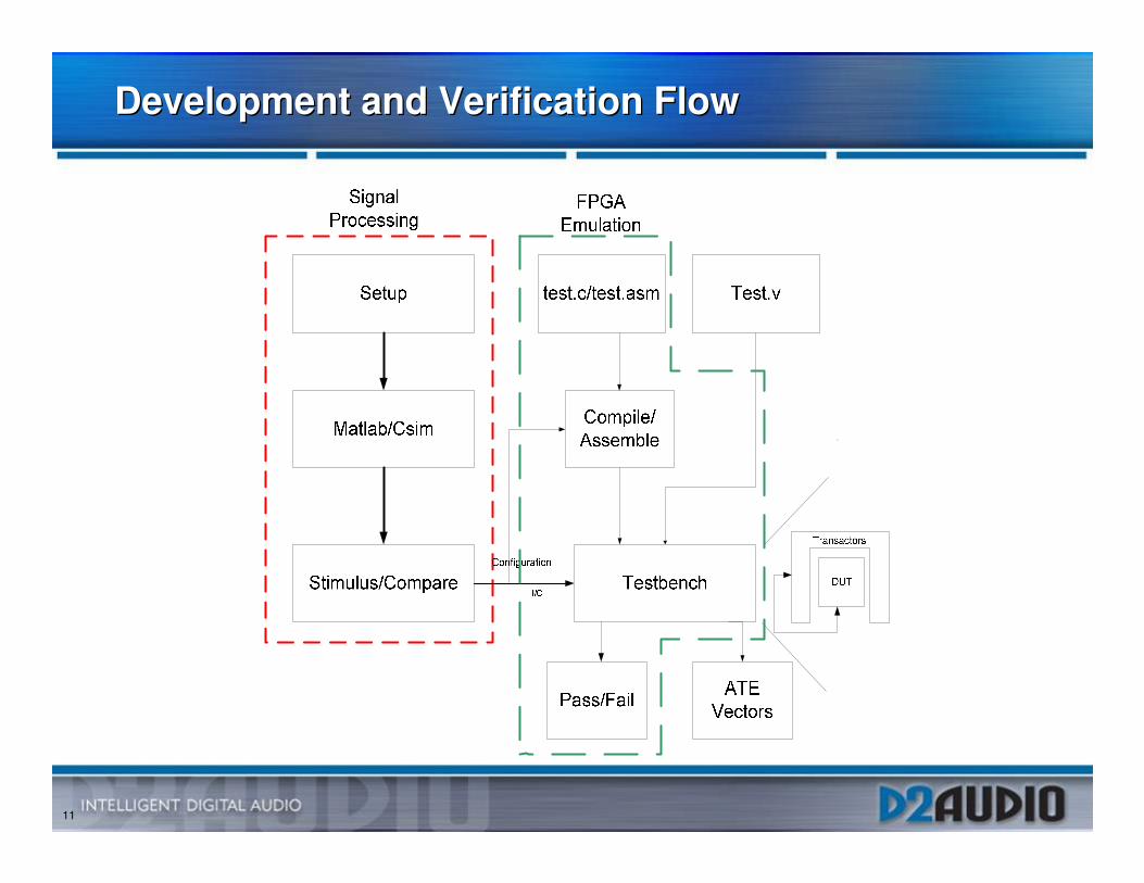
Development and Verification FlowDevelopment and Verification Flow
12
Development and Verification Flow (Contd.)Development and Verification Flow (Contd.)
• Verification environment � Generate setup files, input and expected output data for the RTL
Simulator. � Verilog based transactor performs RTL initialization, initializes the
computational engine and runs the simulation with input data while it compares output data to the expected data read from files.
� Run Verilog simulations with the cycle accurate model in parallel to verify that the RTL implementation has same functionality and identicalperformance to the original model.
• Run extensive simulations to exercise typical setups as well as the boundaries of the design.
• Typically the output files from Matlab become part of the design data base� Test Suites for regression testing
• Maintain C++ model to match architectural and design changes
13
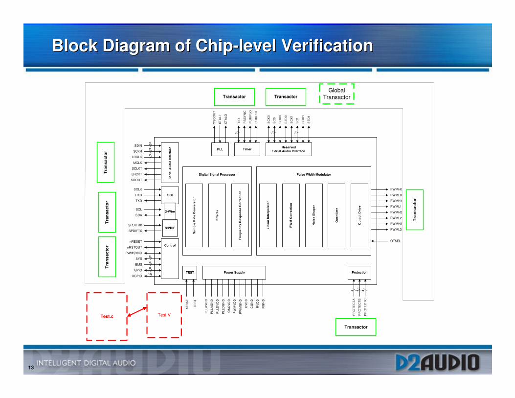
Block Diagram of Chip-level Verification Block Diagram of Chip-level Verification
Power Supply
TE
ST
Ser
ial A
ud
io In
terf
aceSDIN
SCKR
LRCLK
MCLK
SCLKT
LRCKT
SDOUT
2
2
2
ControlnRESET
nRSTOUT
PWMSYNC
SYS
BMS
GPIO
XGPIO
2-WireSCL
SDA
S/PDIFSPDIFRX
SPDIFTX
TEST
5
4
16
8
PLL
OS
CO
UT
XT
ALI
XT
ALO
Timer
TIO
PS
SY
NC
PU
MP
LO
PU
MP
HI
3
PLL
AV
DD
PLL
AG
ND
PLL
DV
DD
PLL
DG
ND
OS
CV
DD
PW
MV
DD
PW
MG
ND
CV
DD
CG
ND
RV
DD
RG
ND
Digital Signal Processor
Sam
ple
Rat
e C
on
vers
ion
Eff
ects
Fre
qu
ency
Res
po
nse
Co
rrec
tio
n
Protection
PR
OT
EC
TA
PR
OT
EC
TB
PR
OT
EC
TC
44
PWMH0
PWML0
PWMH1
PWML1
PWMH2
PWML2
PWMH3
PWML3
OTSEL
nTR
ST
Lin
ear
Inte
rpo
lato
r
PW
M C
orr
ecti
on
No
ise
Sh
aper
Qu
anti
zer
Ou
tpu
t D
rive
ReservedSerial Audio Interface
SC
K0
SC
0
SR
D0
ST
D0
SC
K1
SC
1
SR
D1
ST
D1
3 3
Pulse Width Modulator
4
SCI
SCLK
RXD
TXD
Transactor Transactor
Tra
nsa
cto
rT
ran
sact
or
Tra
nsa
cto
r
Transactor
Tra
nsa
cto
r
GlobalTransactor
Test.c Test.V
14
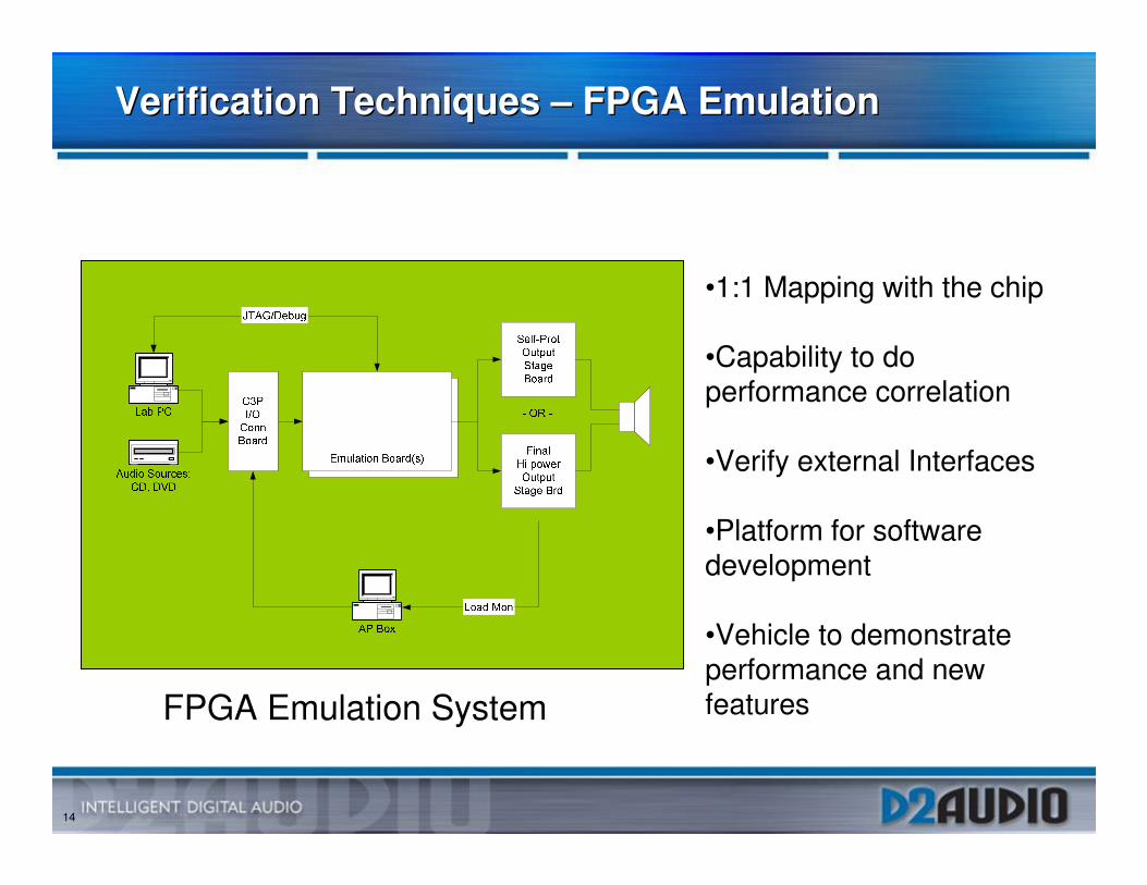
Verification Techniques – FPGA EmulationVerification Techniques – FPGA Emulation
FPGA Emulation System
•1:1 Mapping with the chip
•Capability to do performance correlation
•Verify external Interfaces
•Platform for software development
•Vehicle to demonstrate performance and new features
15
Lessons LearnedLessons Learned
• Always Emulate� Bug count found in FPGA emulation easily justifies effort and
resources expended� Confidence of working with real world interfaces without surprises� Great tool to develop software which allows us to accelerate
firmware development � Emulation system should be scalable, repeatable and
transportable
• Top-level environment where tests can be interchangeably simulated and emulated is very valuable.� Needed to debug emulation system during bring up stages� FPGA was always correlated with RTL� FPGA emulation is used as a hardware accelerator
16
Lessons Learned (Contd.)Lessons Learned (Contd.)
• Code Coverage was useful in finding holes in our test cases
• Project Management � Comprehensive Microsoft Project scheduling with detailed
dependencies between RTL Development, Block-level verification,Chip verification, FPGA and Physical design completion
17
Why the current methodology works for D2AudioWhy the current methodology works for D2Audio
• Comprehensive block-level and system-level specifications
• Easy to use test environment allowed us to generate comprehensive tests
• Everything under CVS control
• Production firmware was run on FPGA emulation before tape-out
• Comprehensive verification in simulation environment before starting FPGA Verification
• FPGA emulation confirmed performance before tape-out� Confirms that the high-level model represents reality
� Plug tests
• Simple verification environment allowed us to scale verificationresources
• Mature engineering team
18
ImprovementsImprovements
• Plan to use assertion tools for debugging, verification and Code/functional coverage
• Add regression suite for FPGA builds
• Evaluate System C/System Verilog � Improve inefficiencies in the current verification environment
• Test Development
• CPU intensive
• Verify external IP for complete functionality and clear specifications
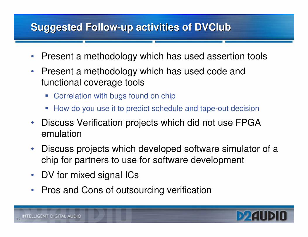
19
Suggested Follow-up activities of DVClubSuggested Follow-up activities of DVClub
• Present a methodology which has used assertion tools
• Present a methodology which has used code and functional coverage tools� Correlation with bugs found on chip
� How do you use it to predict schedule and tape-out decision
• Discuss Verification projects which did not use FPGA emulation
• Discuss projects which developed software simulator of a chip for partners to use for software development
• DV for mixed signal ICs
• Pros and Cons of outsourcing verification