Embed Size (px)
DESCRIPTION
Citation preview
APPLICATION NOTE
Copyright © 2009, Juniper Networks, Inc. 1
CONFIGURING THE 3G EXPRESSCARD ON THE SRX210 SERVICES GATEWAY
2 Copyright © 2009, Juniper Networks, Inc.
APPLICATION NOTE - Configuring the 3G ExpressCard on the SRX210 Services Gateway
Table of Contents
Introduction . . . . . . . . . . . . . . . . . . . . . . . . . . . . . . . . . . . . . . . . . . . . . . . . . . . . . . . . . . . . . . . . . . . . . . . . . . . . . . . . . . . . . . . . . . . . . . . . . . . . . .3
Scope . . . . . . . . . . . . . . . . . . . . . . . . . . . . . . . . . . . . . . . . . . . . . . . . . . . . . . . . . . . . . . . . . . . . . . . . . . . . . . . . . . . . . . . . . . . . . . . . . . . . . . . . . . .3
Design Considerations . . . . . . . . . . . . . . . . . . . . . . . . . . . . . . . . . . . . . . . . . . . . . . . . . . . . . . . . . . . . . . . . . . . . . . . . . . . . . . . . . . . . . . . . . . . .3
Hardware Requirements . . . . . . . . . . . . . . . . . . . . . . . . . . . . . . . . . . . . . . . . . . . . . . . . . . . . . . . . . . . . . . . . . . . . . . . . . . . . . . . . . . . . . . . .3
Software Requirements . . . . . . . . . . . . . . . . . . . . . . . . . . . . . . . . . . . . . . . . . . . . . . . . . . . . . . . . . . . . . . . . . . . . . . . . . . . . . . . . . . . . . . . .3
Compatibility . . . . . . . . . . . . . . . . . . . . . . . . . . . . . . . . . . . . . . . . . . . . . . . . . . . . . . . . . . . . . . . . . . . . . . . . . . . . . . . . . . . . . . . . . . . . . . . . . .3
Card Activation . . . . . . . . . . . . . . . . . . . . . . . . . . . . . . . . . . . . . . . . . . . . . . . . . . . . . . . . . . . . . . . . . . . . . . . . . . . . . . . . . . . . . . . . . . . . . . . .3
Manual Activation . . . . . . . . . . . . . . . . . . . . . . . . . . . . . . . . . . . . . . . . . . . . . . . . . . . . . . . . . . . . . . . . . . . . . . . . . . . . . . . . . . . . . . . . . . . . . .3
Over-The-Air Activation. . . . . . . . . . . . . . . . . . . . . . . . . . . . . . . . . . . . . . . . . . . . . . . . . . . . . . . . . . . . . . . . . . . . . . . . . . . . . . . . . . . . . . . . 4
Over-The-Air-Service Provisioning . . . . . . . . . . . . . . . . . . . . . . . . . . . . . . . . . . . . . . . . . . . . . . . . . . . . . . . . . . . . . . . . . . . . . . . . . . . . . . 4
Configuration . . . . . . . . . . . . . . . . . . . . . . . . . . . . . . . . . . . . . . . . . . . . . . . . . . . . . . . . . . . . . . . . . . . . . . . . . . . . . . . . . . . . . . . . . . . . . . . . . 4
Description and Deployment Scenario . . . . . . . . . . . . . . . . . . . . . . . . . . . . . . . . . . . . . . . . . . . . . . . . . . . . . . . . . . . . . . . . . . . . . . . . . . . . .7
3G Card Used as a Primary Link . . . . . . . . . . . . . . . . . . . . . . . . . . . . . . . . . . . . . . . . . . . . . . . . . . . . . . . . . . . . . . . . . . . . . . . . . . . . . . . . .7
3G Card Used as a Primary Link Configuration . . . . . . . . . . . . . . . . . . . . . . . . . . . . . . . . . . . . . . . . . . . . . . . . . . . . . . . . . . . . . . . . 8
3G Interface Used as a Backup Interface . . . . . . . . . . . . . . . . . . . . . . . . . . . . . . . . . . . . . . . . . . . . . . . . . . . . . . . . . . . . . . . . . . . . . . . .10
Activating the Backup Interface by Monitoring Routes . . . . . . . . . . . . . . . . . . . . . . . . . . . . . . . . . . . . . . . . . . . . . . . . . . . . . . . . . 11
Monitoring . . . . . . . . . . . . . . . . . . . . . . . . . . . . . . . . . . . . . . . . . . . . . . . . . . . . . . . . . . . . . . . . . . . . . . . . . . . . . . . . . . . . . . . . . . . . . . . . . . . . 12
Summary . . . . . . . . . . . . . . . . . . . . . . . . . . . . . . . . . . . . . . . . . . . . . . . . . . . . . . . . . . . . . . . . . . . . . . . . . . . . . . . . . . . . . . . . . . . . . . . . . . . . . . . 14
About Juniper Network . . . . . . . . . . . . . . . . . . . . . . . . . . . . . . . . . . . . . . . . . . . . . . . . . . . . . . . . . . . . . . . . . . . . . . . . . . . . . . . . . . . . . . . . . . . 14
Table of Figures
Figure 1: 3G card as the primary link, using a dial filter . . . . . . . . . . . . . . . . . . . . . . . . . . . . . . . . . . . . . . . . . . . . . . . . . . . . . . . . . . . . . .7
Figure 2: Interface backup . . . . . . . . . . . . . . . . . . . . . . . . . . . . . . . . . . . . . . . . . . . . . . . . . . . . . . . . . . . . . . . . . . . . . . . . . . . . . . . . . . . . . . .10
Figure 3: Prefix watch-list . . . . . . . . . . . . . . . . . . . . . . . . . . . . . . . . . . . . . . . . . . . . . . . . . . . . . . . . . . . . . . . . . . . . . . . . . . . . . . . . . . . . . . . . 11
List of Tables
Table 1: SRX210 Wireless Express Card Support . . . . . . . . . . . . . . . . . . . . . . . . . . . . . . . . . . . . . . . . . . . . . . . . . . . . . . . . . . . . . . . . . . .3
Copyright © 2009, Juniper Networks, Inc. 3
APPLICATION NOTE - Configuring the 3G ExpressCard on the SRX210 Services Gateway
Introduction
With the introduction of Juniper Networks® SRX210 Services Gateway, Juniper has added the capability to use third-
generation (3G) wireless express as a WAN interface. The 3G ExpressCcard can either be used as a backup or a primary
WAN link supporting Evolution-Data Optimized (EVDO), Code Division Multiple Access (CDMA), universal mobile
telecommunications system (UMTS), High Speed Packet Access (HSPA), or Global System for Mobile Communications
(GSM) standards.
Scope
The purpose of this application note is to provide an overview of how to configure and deploy the Wireless 3G ExpressCard
on SRX210 Services Gateways. Depending on the use case scenario, several backup options are being presented.
Design Considerations
This document assumes that the network service has been negotiated with a certified carrier, and that coverage is
available in the area where the SRX210 is deployed.
Hardware Requirements
• Juniper Networks SRX210 Services Gateway
Software Requirements
• Juniper Networks Junos® operating system release 9.5 or later
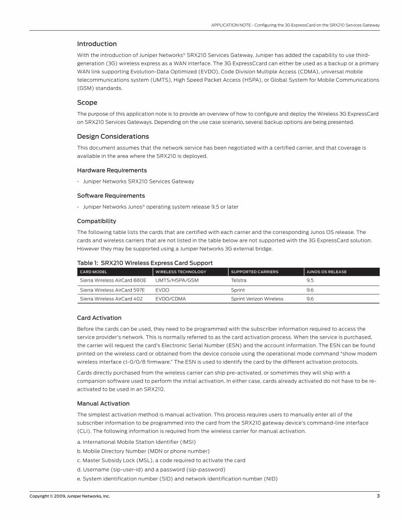
Compatibility
The following table lists the cards that are certified with each carrier and the corresponding Junos OS release. The
cards and wireless carriers that are not listed in the table below are not supported with the 3G ExpressCard solution.
However they may be supported using a Juniper Networks 3G external bridge.
Table 1: SRX210 Wireless Express Card SupportCARD MODEL WIRELESS TECHNOLOGY SUPPORTED CARRIERS JUNOS OS RELEASE
Sierra Wireless AirCard 880E UMTS/HSPA/GSM Telstra 9.5
Sierra Wireless AirCard 597E EVDO Sprint 9.6
Sierra Wireless AirCard 402 EVDO/CDMA Sprint Verizon Wireless 9.6
Card Activation
Before the cards can be used, they need to be programmed with the subscriber information required to access the
service provider’s network. This is normally referred to as the card activation process. When the service is purchased,
the carrier will request the card’s Electronic Serial Number (ESN) and the account information. The ESN can be found
printed on the wireless card or obtained from the device console using the operational mode command “show modem
wireless interface cl-0/0/8 firmware.” The ESN is used to identify the card by the different activation protocols.
Cards directly purchased from the wireless carrier can ship pre-activated, or sometimes they will ship with a
companion software used to perform the initial activation. In either case, cards already activated do not have to be re-
activated to be used in an SRX210.
Manual Activation
The simplest activation method is manual activation. This process requires users to manually enter all of the
subscriber information to be programmed into the card from the SRX210 gateway device’s command-line interface
(CLI). The following information is required from the wireless carrier for manual activation.
a. International Mobile Station Identifier (IMSI)
b. Mobile Directory Number (MDN or phone number)
c. Master Subsidy Lock (MSL), a code required to activate the card
d. Username (sip-user-id) and a password (sip-password)
e. System identification number (SID) and network identification number (NID)
4 Copyright © 2009, Juniper Networks, Inc.
APPLICATION NOTE - Configuring the 3G ExpressCard on the SRX210 Services Gateway
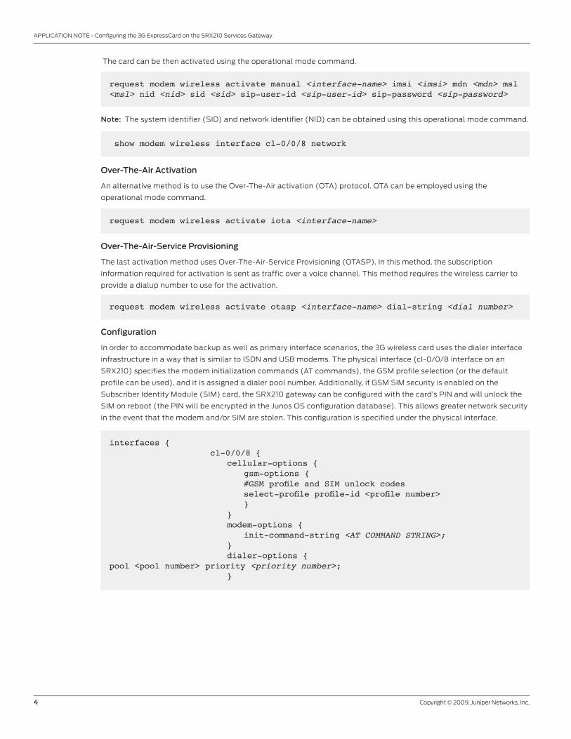
The card can be then activated using the operational mode command.
request modem wireless activate manual <interface-name> imsi <imsi> mdn <mdn> msl <msl> nid <nid> sid <sid> sip-user-id <sip-user-id> sip-password <sip-password>
Note: The system identifier (SID) and network identifier (NID) can be obtained using this operational mode command.
show modem wireless interface cl-0/0/8 network
Over-The-Air Activation
An alternative method is to use the Over-The-Air activation (OTA) protocol. OTA can be employed using the
operational mode command.
request modem wireless activate iota <interface-name>
Over-The-Air-Service Provisioning
The last activation method uses Over-The-Air-Service Provisioning (OTASP). In this method, the subscription
information required for activation is sent as traffic over a voice channel. This method requires the wireless carrier to
provide a dialup number to use for the activation.
request modem wireless activate otasp <interface-name> dial-string <dial number>
Configuration
In order to accommodate backup as well as primary interface scenarios, the 3G wireless card uses the dialer interface
infrastructure in a way that is similar to ISDN and USB modems. The physical interface (cl-0/0/8 interface on an
SRX210) specifies the modem initialization commands (AT commands), the GSM profile selection (or the default
profile can be used), and it is assigned a dialer pool number. Additionally, if GSM SIM security is enabled on the
Subscriber Identity Module (SIM) card, the SRX210 gateway can be configured with the card’s PIN and will unlock the
SIM on reboot (the PIN will be encrypted in the Junos OS configuration database). This allows greater network security
in the event that the modem and/or SIM are stolen. This configuration is specified under the physical interface.
interfaces { cl-0/0/8 { cellular-options { gsm-options { #GSM profile and SIM unlock codes select-profile profile-id <profile number> } } modem-options { init-command-string <AT COMMAND STRING>; } dialer-options {pool <pool number> priority <priority number>; }

Copyright © 2009, Juniper Networks, Inc. 5
APPLICATION NOTE - Configuring the 3G ExpressCard on the SRX210 Services Gateway
If desired, SIM security can be used to prevent unauthorized use of the 3G card. In such cases, the following command
will store the card’s PIN in the configuration (this is an interactive configuration command).
A logical interface, the dialer interface (dl0), is used to trigger calls. When traffic is sent to the dl0 interface, this
interface enables the physical interfaces in the dialer pool and places calls through them. In the particular case of the
3G wireless interface, since a single card is supported, the dialer interface will always refer to a dialer pool with only one
3G card in it.
The dialer interface is used to terminate PPP and IP, so it holds all of the point-to-point protocol (PPP) and
IP-related configurations.
interfaces { dl0 { unit <unit number> { family inet { negotiate-address | <address>; filter { dialer <dialer filter name>; input|output <packet filter name(s)>; } dialer-options { pool <dialer pool number>; idle-timeout <idle timeout value>; dial-string <dial number>; watch-list { <prefix> }; } } }
set interfaces cl-0/0/8 cellular-options gsm-options sim-unlock-code
It is also possible to unlock the SIM card using the operational command.
request modem wireless gsm sim-unlock cl-0/0/8 pin <pin>
The “show modem wireless” command can be used to verify the SIM’s security status.
show modem wireless interface cl-0/0/8Wireless modem firmware details… Modem PIN security status: Enabled SIM status: SIM Okay SIM lock: Unlocked SIM user operation needed: No Op Retries remaining: 3
If a GSM 3G modem is being used to access a secure resource such as an L3VPN, the modem and the router must
be configured to use Password Authentication Protocol (PAP) or Challenge Handshake Authentication Protocol
(CHAP) authentication. The Junos OS CLI provides the means to create multiple profiles on the 3G Express Card. The
authentication information needs to match those provided by the service provider.
request modem wireless gsm create-profile profile-id 2 access-point-name l3vpn.corp authentication-method chap sip-user-id [email protected] sip-password password
6 Copyright © 2009, Juniper Networks, Inc.
APPLICATION NOTE - Configuring the 3G ExpressCard on the SRX210 Services Gateway
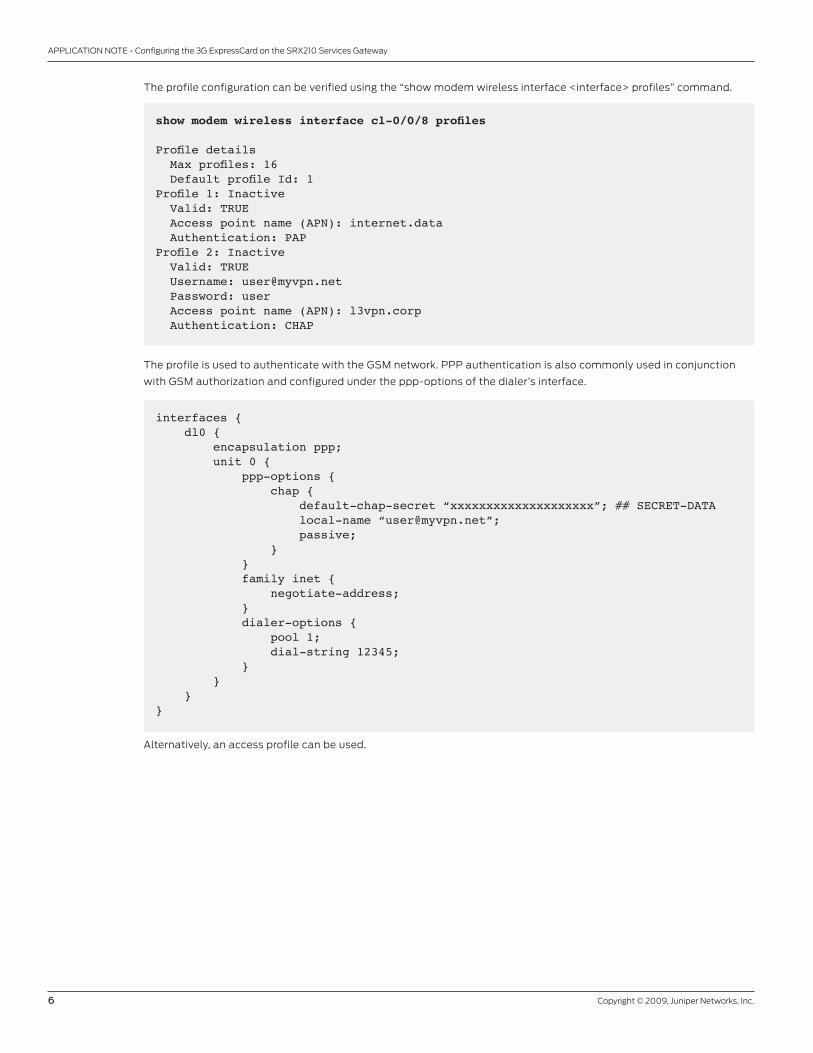
The profile configuration can be verified using the “show modem wireless interface <interface> profiles” command.
show modem wireless interface cl-0/0/8 profiles
Profile details Max profiles: 16 Default profile Id: 1 Profile 1: Inactive Valid: TRUE Access point name (APN): internet.data Authentication: PAPProfile 2: Inactive Valid: TRUE Username: [email protected] Password: user Access point name (APN): l3vpn.corp Authentication: CHAP
The profile is used to authenticate with the GSM network. PPP authentication is also commonly used in conjunction
with GSM authorization and configured under the ppp-options of the dialer’s interface.
interfaces { dl0 { encapsulation ppp; unit 0 { ppp-options { chap { default-chap-secret “xxxxxxxxxxxxxxxxxxxx”; ## SECRET-DATA local-name “[email protected]”; passive; } } family inet { negotiate-address; } dialer-options { pool 1; dial-string 12345; } } }}
Alternatively, an access profile can be used.

Copyright © 2009, Juniper Networks, Inc. 7
APPLICATION NOTE - Configuring the 3G ExpressCard on the SRX210 Services Gateway
Note: The 880E uses UMTS_CHAP_SRVR as the responder ID, and the access profile needs to match on that.
interfaces { dl0 { encapsulation ppp; unit 0 { ppp-options { chap { access-profile 3g; local-name “[email protected]”; passive; } } family inet { negotiate-address; } dialer-options { pool 1; dial-string 12345; } } }}
access { profile 3g { client UMTS_CHAP_SRVR chap-secret “xxxxxxxxxxxxxxxxxxxxxxxx”; ## SECRET-DATA }}
Description and Deployment Scenario
In the following section, we will discuss several common deployment scenarios and provide the associated configurations
for these. For the sake of simplicity, the configuration shown is the one required for an EVDO/CDMA-based network. The
configuration for a GSM network will only differ on the GSM options as previously shown.
3G Card Used as a Primary Link
This first scenario shows the configuration of the 3G card and dialer interface to be used as the primary WAN interface.
Figure 1: 3G card as the primary link, using a dial filter
10.0.1.0/24Trust Zone
INTERNETSRX210
OFFICE
3G card as a primary WAN link
8 Copyright © 2009, Juniper Networks, Inc.
APPLICATION NOTE - Configuring the 3G ExpressCard on the SRX210 Services Gateway
In this mode, the dialer interface is normally up, even when the underlying interface (the cl-0/0/8 interface) might
be down. A static default route is configured pointing to the dl0.0 interface and, while no interesting traffic is being
received on this interface, the underlying wireless interface will be disabled.
A dialer filter is used to mark traffic as “interesting.” When the dl0 interface receives interesting traffic, it will trigger a
connection enabling the wireless WAN interface, and a PPP session will be established through the 3G WAN network. If
no interesting traffic is received after a configurable “idle-timeout” time, the PPP session will be disconnected and the
cl-0/0/8 interface will be disabled.
For completeness, this example includes the security zone, security policies, and basic Network Address Translation
(NAT) configuration.
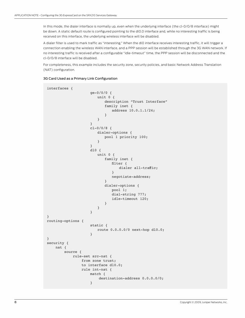
3G Card Used as a Primary Link Configuration
interfaces { ge-0/0/0 { unit 0 { description “Trust Interface” family inet { address 10.0.1.1/24; } } } cl-0/0/8 { dialer-options { pool 1 priority 100; } } dl0 { unit 0 { family inet { filter { dialer all-traffic; } negotiate-address; } dialer-options { pool 1; dial-string 777; idle-timeout 120; } } }}routing-options { static { route 0.0.0.0/0 next-hop dl0.0; }}security { nat { source { rule-set src-nat { from zone trust; to interface dl0.0; rule int-nat { match { destination-address 0.0.0.0/0; }
Copyright © 2009, Juniper Networks, Inc. 9
APPLICATION NOTE - Configuring the 3G ExpressCard on the SRX210 Services Gateway
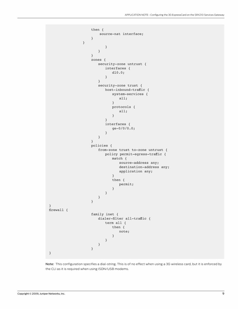
then { source-nat interface; } } } } } zones { security-zone untrust { interfaces { dl0.0; } } security-zone trust { host-inbound-traffic { system-services { all; } protocols { all; } } interfaces { ge-0/0/0.0; } } } policies { from-zone trust to-zone untrust { policy permit-egress-traffic { match { source-address any; destination-address any; application any; } then { permit; } } } }}firewall { family inet { dialer-filter all-traffic { term all { then { note; } } } }}
Note: This configuration specifies a dial-string. This is of no effect when using a 3G wireless card, but it is enforced by
the CLI as it is required when using ISDN/USB modems.
10 Copyright © 2009, Juniper Networks, Inc.
APPLICATION NOTE - Configuring the 3G ExpressCard on the SRX210 Services Gateway
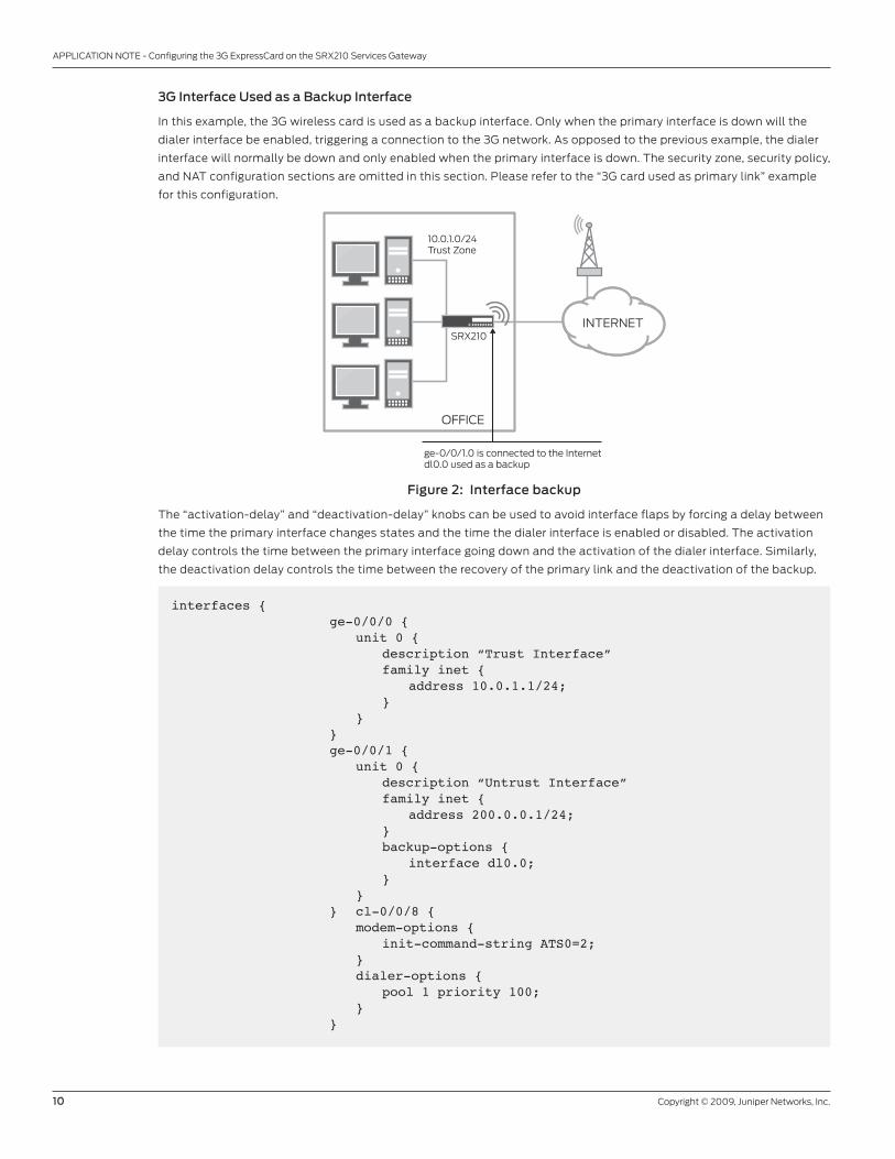
3G Interface Used as a Backup Interface
In this example, the 3G wireless card is used as a backup interface. Only when the primary interface is down will the
dialer interface be enabled, triggering a connection to the 3G network. As opposed to the previous example, the dialer
interface will normally be down and only enabled when the primary interface is down. The security zone, security policy,
and NAT configuration sections are omitted in this section. Please refer to the “3G card used as primary link” example
for this configuration.
Figure 2: Interface backup
The “activation-delay” and “deactivation-delay” knobs can be used to avoid interface flaps by forcing a delay between
the time the primary interface changes states and the time the dialer interface is enabled or disabled. The activation
delay controls the time between the primary interface going down and the activation of the dialer interface. Similarly,
the deactivation delay controls the time between the recovery of the primary link and the deactivation of the backup.
SRX210
OFFICE
10.0.1.0/24Trust Zone
ge-0/0/1.0 is connected to the Internetdl0.0 used as a backup
INTERNET
interfaces { ge-0/0/0 { unit 0 { description “Trust Interface” family inet { address 10.0.1.1/24; } } } ge-0/0/1 { unit 0 { description “Untrust Interface” family inet { address 200.0.0.1/24; } backup-options { interface dl0.0; } } } cl-0/0/8 { modem-options { init-command-string ATS0=2; } dialer-options { pool 1 priority 100; } }

Copyright © 2009, Juniper Networks, Inc. 11
APPLICATION NOTE - Configuring the 3G ExpressCard on the SRX210 Services Gateway
dl0 { unit 0 { family inet { negotiate-address; } dialer-options { pool 1; dial-string 777; activation-delay 60; deactivation-delay 60; } } }}routing-options { static { route 0.0.0.0/0 next-hop [ dl0.0 200.0.0.2 ]; }}
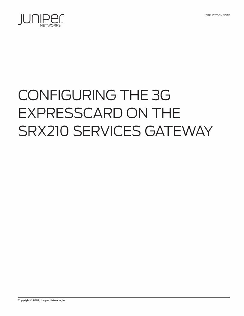
Activating the Backup Interface by Monitoring Routes
Although quite simple, our previous example presents a major drawback—the primary interface’s status is not always
a good indicator of the network’s connectivity. In some instances, when the layer 2 protocols are not able to detect
end-to-end failures, or when multiple network hops separate the SRX210 from the remote resources, other means to
trigger a failover are desired. This example shows how to configure a set of prefix watch-lists which, when they are not
present in the routing table, will enable the dialer interface. Static routes with Bidirectional Forwarding Detection (BFD)
monitoring or routing protocols can be used to dynamically change the status of the routes in the routing table. The
security zone, security policy, and NAT configuration sections are omitted in this section. Please refer to the “3G card
used as primary link” example for this configuration.
Figure 3: Prefix watch-list
SRX210
SRX Series Cluster
OFFICE DATA CENTER
10.0.1.0/24Trust Zone
ge-0/0/1.0 is connected to the Internetdl0.0 used as a backup 10/8 prefix advertised through OSPF
Video
Apps
Data
Finance
WAN
INTERNET

12 Copyright © 2009, Juniper Networks, Inc.
APPLICATION NOTE - Configuring the 3G ExpressCard on the SRX210 Services Gateway
interfaces { ge-0/0/0 { unit 0 { family inet { address 10.0.1.1/24; } } } ge-0/0/1 { unit 0 { family inet { address 200.0.0.2/24; } } } cl-0/0/8 { dialer-options { pool 1 priority 100; } } dl0 { unit 0 { family inet { negotiate-address; } dialer-options { pool 1; dial-string 777; watch-list { 10.0.0.0/8; } } } }}
Monitoring
The show interface command is useful to detect the dialer interface’s status.
show interface dl0Physical interface: dl0, Enabled, Physical link is Up Interface index: 128, SNMP ifIndex: 147 Type: 27, Link-level type: PPP, MTU: 1504 Device flags : Present Running Interface flags: SNMP-Traps Link type : Full-Duplex Link flags : Keepalives Last flapped : Never Input rate : 168 bps (1 pps) Output rate : 0 bps (0 pps)
Logical interface dl0.0 (Index 68) (SNMP ifIndex 148) Flags: Point-To-Point SNMP-Traps 0x0 LinkAddress 23-0 Encapsulation: PPP Dialer: State: Active, Dial pool: 1 Dial strings: 777 Subordinate interfaces: cl-0/0/8 (Index 140)
Copyright © 2009, Juniper Networks, Inc. 13
APPLICATION NOTE - Configuring the 3G ExpressCard on the SRX210 Services Gateway
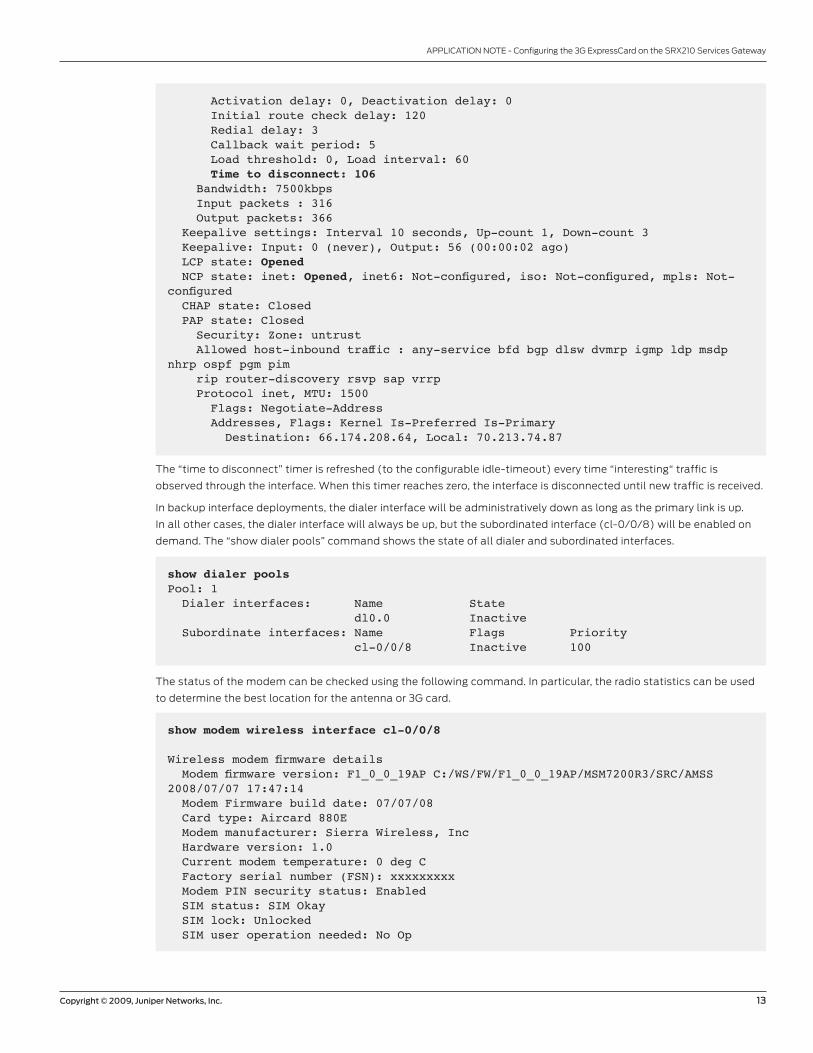
Activation delay: 0, Deactivation delay: 0 Initial route check delay: 120 Redial delay: 3 Callback wait period: 5 Load threshold: 0, Load interval: 60 Time to disconnect: 106 Bandwidth: 7500kbps Input packets : 316 Output packets: 366 Keepalive settings: Interval 10 seconds, Up-count 1, Down-count 3 Keepalive: Input: 0 (never), Output: 56 (00:00:02 ago) LCP state: Opened NCP state: inet: Opened, inet6: Not-configured, iso: Not-configured, mpls: Not-configured CHAP state: Closed PAP state: Closed Security: Zone: untrust Allowed host-inbound traffic : any-service bfd bgp dlsw dvmrp igmp ldp msdp nhrp ospf pgm pim rip router-discovery rsvp sap vrrp Protocol inet, MTU: 1500 Flags: Negotiate-Address Addresses, Flags: Kernel Is-Preferred Is-Primary Destination: 66.174.208.64, Local: 70.213.74.87
The “time to disconnect” timer is refreshed (to the configurable idle-timeout) every time “interesting“ traffic is
observed through the interface. When this timer reaches zero, the interface is disconnected until new traffic is received.
In backup interface deployments, the dialer interface will be administratively down as long as the primary link is up.
In all other cases, the dialer interface will always be up, but the subordinated interface (cl-0/0/8) will be enabled on
demand. The “show dialer pools” command shows the state of all dialer and subordinated interfaces.
show dialer pools Pool: 1 Dialer interfaces: Name State dl0.0 Inactive Subordinate interfaces: Name Flags Priority cl-0/0/8 Inactive 100
The status of the modem can be checked using the following command. In particular, the radio statistics can be used
to determine the best location for the antenna or 3G card.
show modem wireless interface cl-0/0/8
Wireless modem firmware details Modem firmware version: F1_0_0_19AP C:/WS/FW/F1_0_0_19AP/MSM7200R3/SRC/AMSS 2008/07/07 17:47:14 Modem Firmware build date: 07/07/08 Card type: Aircard 880E Modem manufacturer: Sierra Wireless, Inc Hardware version: 1.0 Current modem temperature: 0 deg C Factory serial number (FSN): xxxxxxxxx Modem PIN security status: Enabled SIM status: SIM Okay SIM lock: Unlocked SIM user operation needed: No Op

14 Copyright © 2009, Juniper Networks, Inc.
APPLICATION NOTE - Configuring the 3G ExpressCard on the SRX210 Services Gateway
3500172-001-EN Nov 2009
Copyright 2009 Juniper Networks, Inc. All rights reserved. Juniper Networks, the Juniper Networks logo, Junos, NetScreen, and ScreenOS are registered trademarks of Juniper Networks, Inc. in the United States and other countries. All other trademarks, service marks, registered marks, or registered service marks are the property of their respective owners. Juniper Networks assumes no responsibility for any inaccuracies in this document. Juniper Networks reserves the right to change, modify, transfer, or otherwise revise this publication without notice.
EMEA Headquarters
Juniper Networks Ireland
Airside Business Park
Swords, County Dublin, Ireland
Phone: 35.31.8903.600
EMEA Sales: 00800.4586.4737
Fax: 35.31.8903.601
APAC Headquarters
Juniper Networks (Hong Kong)
26/F, Cityplaza One
1111 King’s Road
Taikoo Shing, Hong Kong
Phone: 852.2332.3636
Fax: 852.2574.7803
Corporate and Sales Headquarters
Juniper Networks, Inc.
1194 North Mathilda Avenue
Sunnyvale, CA 94089 USA
Phone: 888.JUNIPER (888.586.4737)
or 408.745.2000
Fax: 408.745.2100
www.juniper.net
To purchase Juniper Networks solutions,
please contact your Juniper Networks
representative at 1-866-298-6428 or
authorized reseller.
Printed on recycled paper
Retries remaining: 3Wireless Modem Network Info Current Modem Status: Online Current Service Status: Offline Current Service Type: Combo(CS,PS) Current Service Mode: HSDPA Current Band: 259 Roaming Status: No Network Selection Mode: Automatic Network: AUS Mobile Country Code (MCC): 505 Mobile Network Code (MNC): 1 Location Area Code (LAC): 8784 Routing Area Code (RAC): 1 Cell Identification: 3461 Scrambling Code: 264Radio statistics Current radio signal strength: -74 dB
Summary
With the almost ubiquitous presence of mobile networks, the 3G ExpressCard on Juniper Networks SRX210 Services
Gateway offers a cost-effective way to provide primary links and backup wireless connections that are easy to install.
Alternatively, when the bandwidth requirements are not large, the wireless network can be used to provide connectivity
to small branch offices in a way that is very simple to use and deploy.
About Juniper Network
Juniper Networks, Inc. is the leader in high-performance networking. Juniper offers a high-performance network
infrastructure that creates a responsive and trusted environment for accelerating the deployment of services and
applications over a single network. This fuels high-performance businesses. Additional information can be found at
www.juniper.net.