Embed Size (px)
Citation preview

Junos®OS
SRX100, SRX210, SRX220, SRX240, and SRX650Services Gateways MIB Reference
Release
10.4
Published: 2010-11-11
Revision 01
Copyright © 2010, Juniper Networks, Inc.

Juniper Networks, Inc.1194 North Mathilda AvenueSunnyvale, California 94089USA408-745-2000www.juniper.net
This product includes the Envoy SNMP Engine, developed by Epilogue Technology, an Integrated Systems Company. Copyright © 1986-1997,Epilogue Technology Corporation. All rights reserved. This program and its documentation were developed at private expense, and no partof them is in the public domain.
This product includes memory allocation software developed by Mark Moraes, copyright © 1988, 1989, 1993, University of Toronto.
This product includes FreeBSD software developed by the University of California, Berkeley, and its contributors. All of the documentationand software included in the 4.4BSD and 4.4BSD-Lite Releases is copyrighted by the Regents of the University of California. Copyright ©1979, 1980, 1983, 1986, 1988, 1989, 1991, 1992, 1993, 1994. The Regents of the University of California. All rights reserved.
GateD software copyright © 1995, the Regents of the University. All rights reserved. Gate Daemon was originated and developed throughrelease 3.0 by Cornell University and its collaborators. Gated is based on Kirton’s EGP, UC Berkeley’s routing daemon (routed), and DCN’sHELLO routing protocol. Development of Gated has been supported in part by the National Science Foundation. Portions of the GateDsoftware copyright © 1988, Regents of the University of California. All rights reserved. Portions of the GateD software copyright © 1991, D.L. S. Associates.
This product includes software developed by Maker Communications, Inc., copyright © 1996, 1997, Maker Communications, Inc.
Juniper Networks, Junos, Steel-Belted Radius, NetScreen, and ScreenOS are registered trademarks of Juniper Networks, Inc. in the UnitedStates and other countries. The Juniper Networks Logo, the Junos logo, and JunosE are trademarks of Juniper Networks, Inc. All othertrademarks, service marks, registered trademarks, or registered service marks are the property of their respective owners.
Juniper Networks assumes no responsibility for any inaccuracies in this document. Juniper Networks reserves the right to change, modify,transfer, or otherwise revise this publication without notice.
Products made or sold by Juniper Networks or components thereof might be covered by one or more of the following patents that areowned by or licensed to Juniper Networks: U.S. Patent Nos. 5,473,599, 5,905,725, 5,909,440, 6,192,051, 6,333,650, 6,359,479, 6,406,312,6,429,706, 6,459,579, 6,493,347, 6,538,518, 6,538,899, 6,552,918, 6,567,902, 6,578,186, and 6,590,785.
SRX100, SRX210, SRX220, SRX240, and SRX650 Services Gateways MIB ReferenceRelease 10.4Copyright © 2010, Juniper Networks, Inc.All rights reserved. Printed in USA.
Revision HistoryOctober 2010—Revision 01
The information in this document is current as of the date listed in the revision history.
YEAR 2000 NOTICE
Juniper Networks hardware and software products are Year 2000 compliant. The Junos OS has no known time-related limitations throughthe year 2038. However, the NTP application is known to have some difficulty in the year 2036.
Copyright © 2010, Juniper Networks, Inc.ii

ENDUSER LICENSE AGREEMENT
READ THIS ENDUSER LICENSE AGREEMENT (“AGREEMENT”) BEFORE DOWNLOADING, INSTALLING, ORUSING THE SOFTWARE.BY DOWNLOADING, INSTALLING, OR USING THE SOFTWARE OR OTHERWISE EXPRESSING YOUR AGREEMENT TO THE TERMSCONTAINED HEREIN, YOU (AS CUSTOMER OR IF YOU ARE NOT THE CUSTOMER, AS A REPRESENTATIVE/AGENT AUTHORIZED TOBIND THE CUSTOMER) CONSENT TO BE BOUND BY THIS AGREEMENT. IF YOU DO NOT OR CANNOT AGREE TO THE TERMS CONTAINEDHEREIN, THEN (A) DO NOT DOWNLOAD, INSTALL, OR USE THE SOFTWARE, AND (B) YOU MAY CONTACT JUNIPER NETWORKSREGARDING LICENSE TERMS.
1. The Parties. The parties to this Agreement are (i) Juniper Networks, Inc. (if the Customer’s principal office is located in the Americas) orJuniper Networks (Cayman) Limited (if the Customer’s principal office is located outside the Americas) (such applicable entity being referredto herein as “Juniper”), and (ii) the person or organization that originally purchased from Juniper or an authorized Juniper reseller the applicablelicense(s) for use of the Software (“Customer”) (collectively, the “Parties”).
2. The Software. In this Agreement, “Software” means the program modules and features of the Juniper or Juniper-supplied software, forwhich Customer has paid the applicable license or support fees to Juniper or an authorized Juniper reseller, or which was embedded byJuniper in equipment which Customer purchased from Juniper or an authorized Juniper reseller. “Software” also includes updates, upgradesand new releases of such software. “Embedded Software” means Software which Juniper has embedded in or loaded onto the Juniperequipment and any updates, upgrades, additions or replacements which are subsequently embedded in or loaded onto the equipment.
3. LicenseGrant.Subject to payment of the applicable fees and the limitations and restrictions set forth herein, Juniper grants to Customera non-exclusive and non-transferable license, without right to sublicense, to use the Software, in executable form only, subject to thefollowing use restrictions:
a. Customer shall use Embedded Software solely as embedded in, and for execution on, Juniper equipment originally purchased byCustomer from Juniper or an authorized Juniper reseller.
b. Customer shall use the Software on a single hardware chassis having a single processing unit, or as many chassis or processing unitsfor which Customer has paid the applicable license fees; provided, however, with respect to the Steel-Belted Radius or Odyssey AccessClient software only, Customer shall use such Software on a single computer containing a single physical random access memory spaceand containing any number of processors. Use of the Steel-Belted Radius or IMS AAA software on multiple computers or virtual machines(e.g., Solaris zones) requires multiple licenses, regardless of whether such computers or virtualizations are physically contained on a singlechassis.
c. Product purchase documents, paper or electronic user documentation, and/or the particular licenses purchased by Customer mayspecify limits to Customer’s use of the Software. Such limits may restrict use to a maximum number of seats, registered endpoints, concurrentusers, sessions, calls, connections, subscribers, clusters, nodes, realms, devices, links, ports or transactions, or require the purchase ofseparate licenses to use particular features, functionalities, services, applications, operations, or capabilities, or provide throughput,performance, configuration, bandwidth, interface, processing, temporal, or geographical limits. In addition, such limits may restrict the useof the Software to managing certain kinds of networks or require the Software to be used only in conjunction with other specific Software.Customer’s use of the Software shall be subject to all such limitations and purchase of all applicable licenses.
d. For any trial copy of the Software, Customer’s right to use the Software expires 30 days after download, installation or use of theSoftware. Customer may operate the Software after the 30-day trial period only if Customer pays for a license to do so. Customer may notextend or create an additional trial period by re-installing the Software after the 30-day trial period.
e. The Global Enterprise Edition of the Steel-Belted Radius software may be used by Customer only to manage access to Customer’senterprise network. Specifically, service provider customers are expressly prohibited from using the Global Enterprise Edition of theSteel-Belted Radius software to support any commercial network access services.
The foregoing license is not transferable or assignable by Customer. No license is granted herein to any user who did not originally purchasethe applicable license(s) for the Software from Juniper or an authorized Juniper reseller.
4. Use Prohibitions. Notwithstanding the foregoing, the license provided herein does not permit the Customer to, and Customer agreesnot to and shall not: (a) modify, unbundle, reverse engineer, or create derivative works based on the Software; (b) make unauthorizedcopies of the Software (except as necessary for backup purposes); (c) rent, sell, transfer, or grant any rights in and to any copy of theSoftware, in any form, to any third party; (d) remove any proprietary notices, labels, or marks on or in any copy of the Software or any productin which the Software is embedded; (e) distribute any copy of the Software to any third party, including as may be embedded in Juniperequipment sold in the secondhand market; (f) use any ‘locked’ or key-restricted feature, function, service, application, operation, or capabilitywithout first purchasing the applicable license(s) and obtaining a valid key from Juniper, even if such feature, function, service, application,operation, or capability is enabled without a key; (g) distribute any key for the Software provided by Juniper to any third party; (h) use the
iiiCopyright © 2010, Juniper Networks, Inc.
Software in any manner that extends or is broader than the uses purchased by Customer from Juniper or an authorized Juniper reseller; (i)use Embedded Software on non-Juniper equipment; (j) use Embedded Software (or make it available for use) on Juniper equipment thatthe Customer did not originally purchase from Juniper or an authorized Juniper reseller; (k) disclose the results of testing or benchmarkingof the Software to any third party without the prior written consent of Juniper; or (l) use the Software in any manner other than as expresslyprovided herein.
5. Audit. Customer shall maintain accurate records as necessary to verify compliance with this Agreement. Upon request by Juniper,Customer shall furnish such records to Juniper and certify its compliance with this Agreement.
6. Confidentiality. The Parties agree that aspects of the Software and associated documentation are the confidential property of Juniper.As such, Customer shall exercise all reasonable commercial efforts to maintain the Software and associated documentation in confidence,which at a minimum includes restricting access to the Software to Customer employees and contractors having a need to use the Softwarefor Customer’s internal business purposes.
7. Ownership. Juniper and Juniper’s licensors, respectively, retain ownership of all right, title, and interest (including copyright) in and tothe Software, associated documentation, and all copies of the Software. Nothing in this Agreement constitutes a transfer or conveyanceof any right, title, or interest in the Software or associated documentation, or a sale of the Software, associated documentation, or copiesof the Software.
8. Warranty, Limitation of Liability, Disclaimer ofWarranty. The warranty applicable to the Software shall be as set forth in the warrantystatement that accompanies the Software (the “Warranty Statement”). Nothing in this Agreement shall give rise to any obligation to supportthe Software. Support services may be purchased separately. Any such support shall be governed by a separate, written support servicesagreement. TO THE MAXIMUM EXTENT PERMITTED BY LAW, JUNIPER SHALL NOT BE LIABLE FOR ANY LOST PROFITS, LOSS OF DATA,OR COSTS OR PROCUREMENT OF SUBSTITUTE GOODS OR SERVICES, OR FOR ANY SPECIAL, INDIRECT, OR CONSEQUENTIAL DAMAGESARISING OUT OF THIS AGREEMENT, THE SOFTWARE, OR ANY JUNIPER OR JUNIPER-SUPPLIED SOFTWARE. IN NO EVENT SHALL JUNIPERBE LIABLE FOR DAMAGES ARISING FROM UNAUTHORIZED OR IMPROPER USE OF ANY JUNIPER OR JUNIPER-SUPPLIED SOFTWARE.EXCEPT AS EXPRESSLY PROVIDED IN THE WARRANTY STATEMENT TO THE EXTENT PERMITTED BY LAW, JUNIPER DISCLAIMS ANYAND ALL WARRANTIES IN AND TO THE SOFTWARE (WHETHER EXPRESS, IMPLIED, STATUTORY, OR OTHERWISE), INCLUDING ANYIMPLIED WARRANTY OF MERCHANTABILITY, FITNESS FOR A PARTICULAR PURPOSE, OR NONINFRINGEMENT. IN NO EVENT DOESJUNIPER WARRANT THAT THE SOFTWARE, OR ANY EQUIPMENT OR NETWORK RUNNING THE SOFTWARE, WILL OPERATE WITHOUTERROR OR INTERRUPTION, OR WILL BE FREE OF VULNERABILITY TO INTRUSION OR ATTACK. In no event shall Juniper’s or its suppliers’or licensors’ liability to Customer, whether in contract, tort (including negligence), breach of warranty, or otherwise, exceed the price paidby Customer for the Software that gave rise to the claim, or if the Software is embedded in another Juniper product, the price paid byCustomer for such other product. Customer acknowledges and agrees that Juniper has set its prices and entered into this Agreement inreliance upon the disclaimers of warranty and the limitations of liability set forth herein, that the same reflect an allocation of risk betweenthe Parties (including the risk that a contract remedy may fail of its essential purpose and cause consequential loss), and that the sameform an essential basis of the bargain between the Parties.
9. Termination. Any breach of this Agreement or failure by Customer to pay any applicable fees due shall result in automatic terminationof the license granted herein. Upon such termination, Customer shall destroy or return to Juniper all copies of the Software and relateddocumentation in Customer’s possession or control.
10. Taxes. All license fees payable under this agreement are exclusive of tax. Customer shall be responsible for paying Taxes arising fromthe purchase of the license, or importation or use of the Software. If applicable, valid exemption documentation for each taxing jurisdictionshall be provided to Juniper prior to invoicing, and Customer shall promptly notify Juniper if their exemption is revoked or modified. Allpayments made by Customer shall be net of any applicable withholding tax. Customer will provide reasonable assistance to Juniper inconnection with such withholding taxes by promptly: providing Juniper with valid tax receipts and other required documentation showingCustomer’s payment of any withholding taxes; completing appropriate applications that would reduce the amount of withholding tax tobe paid; and notifying and assisting Juniper in any audit or tax proceeding related to transactions hereunder. Customer shall comply withall applicable tax laws and regulations, and Customer will promptly pay or reimburse Juniper for all costs and damages related to anyliability incurred by Juniper as a result of Customer’s non-compliance or delay with its responsibilities herein. Customer’s obligations underthis Section shall survive termination or expiration of this Agreement.
11. Export. Customer agrees to comply with all applicable export laws and restrictions and regulations of any United States and anyapplicable foreign agency or authority, and not to export or re-export the Software or any direct product thereof in violation of any suchrestrictions, laws or regulations, or without all necessary approvals. Customer shall be liable for any such violations. The version of theSoftware supplied to Customer may contain encryption or other capabilities restricting Customer’s ability to export the Software withoutan export license.
Copyright © 2010, Juniper Networks, Inc.iv
12. Commercial Computer Software. The Software is “commercial computer software” and is provided with restricted rights. Use,duplication, or disclosure by the United States government is subject to restrictions set forth in this Agreement and as provided in DFARS227.7201 through 227.7202-4, FAR 12.212, FAR 27.405(b)(2), FAR 52.227-19, or FAR 52.227-14(ALT III) as applicable.
13. Interface Information. To the extent required by applicable law, and at Customer's written request, Juniper shall provide Customerwith the interface information needed to achieve interoperability between the Software and another independently created program, onpayment of applicable fee, if any. Customer shall observe strict obligations of confidentiality with respect to such information and shall usesuch information in compliance with any applicable terms and conditions upon which Juniper makes such information available.
14. Third Party Software.Any licensor of Juniper whose software is embedded in the Software and any supplier of Juniper whose productsor technology are embedded in (or services are accessed by) the Software shall be a third party beneficiary with respect to this Agreement,and such licensor or vendor shall have the right to enforce this Agreement in its own name as if it were Juniper. In addition, certain third partysoftware may be provided with the Software and is subject to the accompanying license(s), if any, of its respective owner(s). To the extentportions of the Software are distributed under and subject to open source licenses obligating Juniper to make the source code for suchportions publicly available (such as the GNU General Public License (“GPL”) or the GNU Library General Public License (“LGPL”)), Juniperwill make such source code portions (including Juniper modifications, as appropriate) available upon request for a period of up to threeyears from the date of distribution. Such request can be made in writing to Juniper Networks, Inc., 1194 N. Mathilda Ave., Sunnyvale, CA
94089, ATTN: General Counsel. You may obtain a copy of the GPL at http://www.gnu.org/licenses/gpl.html, and a copy of the LGPL
at http://www.gnu.org/licenses/lgpl.html .
15. Miscellaneous. This Agreement shall be governed by the laws of the State of California without reference to its conflicts of lawsprinciples. The provisions of the U.N. Convention for the International Sale of Goods shall not apply to this Agreement. For any disputesarising under this Agreement, the Parties hereby consent to the personal and exclusive jurisdiction of, and venue in, the state and federalcourts within Santa Clara County, California. This Agreement constitutes the entire and sole agreement between Juniper and the Customerwith respect to the Software, and supersedes all prior and contemporaneous agreements relating to the Software, whether oral or written(including any inconsistent terms contained in a purchase order), except that the terms of a separate written agreement executed by anauthorized Juniper representative and Customer shall govern to the extent such terms are inconsistent or conflict with terms containedherein. No modification to this Agreement nor any waiver of any rights hereunder shall be effective unless expressly assented to in writingby the party to be charged. If any portion of this Agreement is held invalid, the Parties agree that such invalidity shall not affect the validityof the remainder of this Agreement. This Agreement and associated documentation has been written in the English language, and theParties agree that the English version will govern. (For Canada: Les parties aux présentés confirment leur volonté que cette convention demême que tous les documents y compris tout avis qui s'y rattaché, soient redigés en langue anglaise. (Translation: The parties confirm thatthis Agreement and all related documentation is and will be in the English language)).
vCopyright © 2010, Juniper Networks, Inc.

Copyright © 2010, Juniper Networks, Inc.vi
Abbreviated Table of Contents
About This Guide . . . . . . . . . . . . . . . . . . . . . . . . . . . . . . . . . . . . . . . . . . . . . . . . . xix
Part 1 Network Management Introduction
Chapter 1 Network Management Overview . . . . . . . . . . . . . . . . . . . . . . . . . . . . . . . . . . . . . 3
Part 2 Simple Network Management Protocol (SNMP)
Chapter 2 SNMPOverview . . . . . . . . . . . . . . . . . . . . . . . . . . . . . . . . . . . . . . . . . . . . . . . . . . . . 9
Chapter 3 Configuring SNMP . . . . . . . . . . . . . . . . . . . . . . . . . . . . . . . . . . . . . . . . . . . . . . . . . 37
Chapter 4 Standard SNMP Traps . . . . . . . . . . . . . . . . . . . . . . . . . . . . . . . . . . . . . . . . . . . . . 59
Chapter 5 Juniper Networks Enterprise-Specific SNMP Traps . . . . . . . . . . . . . . . . . . . . 73
Chapter 6 Summary of SNMP Configuration Statements . . . . . . . . . . . . . . . . . . . . . . . . 93
Chapter 7 SNMP Remote Operations . . . . . . . . . . . . . . . . . . . . . . . . . . . . . . . . . . . . . . . . . 115
Chapter 8 SNMP Support for Routing Instances . . . . . . . . . . . . . . . . . . . . . . . . . . . . . . . 127
Chapter 9 SRX100, SRX210, SRX220, SRX240, and SRX650 Services GatewaysSupported Enterprise-Specific MIBs . . . . . . . . . . . . . . . . . . . . . . . . . . . . . . . . 145
Part 3 SRX100, SRX210, SRX220, SRX240, and SRX650 ServicesGateways MIBs
Chapter 10 Interpreting the Structure of Management Information MIB . . . . . . . . . . . 153
Chapter 11 Interpreting the Enterprise-Specific Access Authentication ObjectsMIB . . . . . . . . . . . . . . . . . . . . . . . . . . . . . . . . . . . . . . . . . . . . . . . . . . . . . . . . . . . . . 161
Chapter 12 Interpreting the Enterprise-Specific AlarmMIB . . . . . . . . . . . . . . . . . . . . . . . 165
Chapter 13 Interpreting the Enterprise-Specific BGP4 V2 MIB . . . . . . . . . . . . . . . . . . . . 169
Chapter 14 Interpreting the Enterprise-Specific Bidirectional Forwarding Detection(BFD)MIB . . . . . . . . . . . . . . . . . . . . . . . . . . . . . . . . . . . . . . . . . . . . . . . . . . . . . . . . 171
Chapter 15 Interpreting the Enterprise-Specific Chassis MIBs . . . . . . . . . . . . . . . . . . . . 173
Chapter 16 Interpreting the Enterprise-Specific Configuration Management MIB . . . 269
Chapter 17 Interpreting the Enterprise-Specific Ethernet MAC MIB . . . . . . . . . . . . . . . 275
Chapter 18 Interpreting the Enterprise-Specific Event MIB . . . . . . . . . . . . . . . . . . . . . . . 277
Chapter 19 Interpreting the Enterprise-Specific Firewall MIB . . . . . . . . . . . . . . . . . . . . . 279
Chapter 20 Interpreting the Enterprise-Specific Host Resources MIB . . . . . . . . . . . . . . 283
Chapter 21 Interpreting the Enterprise-Specific InterfaceMIB . . . . . . . . . . . . . . . . . . . . 285
Chapter 22 Interpreting the Enterprise-Specific IP Forward MIB . . . . . . . . . . . . . . . . . . 291
viiCopyright © 2010, Juniper Networks, Inc.

Chapter 23 Interpreting theEnterprise-Specific IPsecGenericFlowMonitoringObjectMIB . . . . . . . . . . . . . . . . . . . . . . . . . . . . . . . . . . . . . . . . . . . . . . . . . . . . . . . . . . . . 293
Chapter 24 Interpreting the Enterprise-Specific IPsec Monitoring MIB . . . . . . . . . . . . 309
Chapter 25 Interpreting the Enterprise-Specific IPv4 MIB . . . . . . . . . . . . . . . . . . . . . . . . 317
Chapter 26 Interpreting the Enterprise-Specific IPv6 MIB . . . . . . . . . . . . . . . . . . . . . . . . 319
Chapter 27 Interpreting theEnterprise-SpecificNetworkAddressTranslationObjectsMIB . . . . . . . . . . . . . . . . . . . . . . . . . . . . . . . . . . . . . . . . . . . . . . . . . . . . . . . . . . . . . 327
Chapter 28 Interpreting the Enterprise-Specific Packet Forwarding Engine MIB . . . . 335
Chapter 29 Interpreting the Enterprise-Specific Ping MIB . . . . . . . . . . . . . . . . . . . . . . . . 339
Chapter 30 Interpreting the Enterprise-Specific Policy Objects MIB . . . . . . . . . . . . . . . 355
Chapter 31 Interpreting the Enterprise-Specific Real-TimeMedia MIB . . . . . . . . . . . . . 361
Chapter 32 Interpreting the Enterprise-Specific Reverse-Path-Forwarding MIB . . . . . 371
Chapter 33 Interpreting the Enterprise-Specific RMON Events and AlarmsMIB . . . . . 373
Chapter 34 Interpreting the Enterprise-Specific Security Interface ExtensionObjectsMIB . . . . . . . . . . . . . . . . . . . . . . . . . . . . . . . . . . . . . . . . . . . . . . . . . . . . . . . . . . . . . 377
Chapter 35 Interpreting the Enterprise-Specific SIP Common MIB . . . . . . . . . . . . . . . . 381
Chapter 36 Interpreting the Enterprise-Specific SNMP IDP MIB . . . . . . . . . . . . . . . . . . 387
Chapter 37 Interpreting the Enterprise-Specific System Log MIB . . . . . . . . . . . . . . . . . 389
Chapter 38 Interpreting the Enterprise-Specific Traceroute MIB . . . . . . . . . . . . . . . . . . 393
Chapter 39 Interpreting the Enterprise-Specific Utility MIB . . . . . . . . . . . . . . . . . . . . . . 395
Chapter 40 Interpreting the Enterprise-Specific VPN Certificate Objects MIB . . . . . . 399
Part 4 Accounting Options
Chapter 41 Accounting Options Overview . . . . . . . . . . . . . . . . . . . . . . . . . . . . . . . . . . . . . 405
Chapter 42 Configuring Accounting Options . . . . . . . . . . . . . . . . . . . . . . . . . . . . . . . . . . . 407
Part 5 Index
Index . . . . . . . . . . . . . . . . . . . . . . . . . . . . . . . . . . . . . . . . . . . . . . . . . . . . . . . . . . . 433
Copyright © 2010, Juniper Networks, Inc.viii
SRX100, SRX210, SRX220, SRX240, and SRX650 Services Gateways MIB Reference
Table of Contents
About This Guide . . . . . . . . . . . . . . . . . . . . . . . . . . . . . . . . . . . . . . . . . . . . . . . . . xix
SRX Series Documentation and Release Notes . . . . . . . . . . . . . . . . . . . . . . . . . . . xix
Objectives . . . . . . . . . . . . . . . . . . . . . . . . . . . . . . . . . . . . . . . . . . . . . . . . . . . . . . . . . xix
Audience . . . . . . . . . . . . . . . . . . . . . . . . . . . . . . . . . . . . . . . . . . . . . . . . . . . . . . . . . . xx
Documentation Conventions . . . . . . . . . . . . . . . . . . . . . . . . . . . . . . . . . . . . . . . . . . xx
Requesting Technical Support . . . . . . . . . . . . . . . . . . . . . . . . . . . . . . . . . . . . . . . . xxii
Self-Help Online Tools and Resources . . . . . . . . . . . . . . . . . . . . . . . . . . . . . . xxiii
Opening a Case with JTAC . . . . . . . . . . . . . . . . . . . . . . . . . . . . . . . . . . . . . . . xxiii
Part 1 Network Management Introduction
Chapter 1 Network Management Overview . . . . . . . . . . . . . . . . . . . . . . . . . . . . . . . . . . . . . 3
Understanding Device Management Functions in Junos OS . . . . . . . . . . . . . . . . . . 3
Part 2 Simple Network Management Protocol (SNMP)
Chapter 2 SNMPOverview . . . . . . . . . . . . . . . . . . . . . . . . . . . . . . . . . . . . . . . . . . . . . . . . . . . . 9
Understanding the SNMP Implementation in Junos OS . . . . . . . . . . . . . . . . . . . . . 9
SNMP Architecture . . . . . . . . . . . . . . . . . . . . . . . . . . . . . . . . . . . . . . . . . . . . . . . 9
Management Information Base (MIB) . . . . . . . . . . . . . . . . . . . . . . . . . . . 10
SNMP Traps and Informs . . . . . . . . . . . . . . . . . . . . . . . . . . . . . . . . . . . . . . 10
Junos SNMP Agent Features . . . . . . . . . . . . . . . . . . . . . . . . . . . . . . . . . . . . . . . 12
Standard SNMP MIBs Supported by Junos OS . . . . . . . . . . . . . . . . . . . . . . . . . . . . 12
Juniper Networks Enterprise-Specific MIBs . . . . . . . . . . . . . . . . . . . . . . . . . . . . . . . 23
Loading MIB Files to a Network Management System . . . . . . . . . . . . . . . . . . . . . . 35
Chapter 3 Configuring SNMP . . . . . . . . . . . . . . . . . . . . . . . . . . . . . . . . . . . . . . . . . . . . . . . . . 37
Configuring SNMP on a Device Running Junos OS . . . . . . . . . . . . . . . . . . . . . . . . . 38
Configuring the System Contact on a Device Running Junos OS . . . . . . . . . . . . . . 40
Configuring the System Location for a Device Running Junos OS . . . . . . . . . . . . . 40
Configuring the System Description on a Device Running Junos OS . . . . . . . . . . . 41
Filtering Duplicate SNMP Requests . . . . . . . . . . . . . . . . . . . . . . . . . . . . . . . . . . . . . 41
Configuring the Commit Delay Timer . . . . . . . . . . . . . . . . . . . . . . . . . . . . . . . . . . . 42
Configuring the System Name . . . . . . . . . . . . . . . . . . . . . . . . . . . . . . . . . . . . . . . . . 42
Configuring the SNMP Community String . . . . . . . . . . . . . . . . . . . . . . . . . . . . . . . . 43
Adding a Group of Clients to an SNMP Community . . . . . . . . . . . . . . . . . . . . . . . . 44
Configuring SNMP Trap Options and Groups on a Device Running Junos OS . . . . 45
Configuring SNMP Trap Options . . . . . . . . . . . . . . . . . . . . . . . . . . . . . . . . . . . . . . . 46
Configuring the Source Address for SNMP Traps . . . . . . . . . . . . . . . . . . . . . . 46
Configuring the Agent Address for SNMP Traps . . . . . . . . . . . . . . . . . . . . . . . 48
Adding snmpTrapEnterprise Object Identifier to Standard SNMP Traps . . . . 49
ixCopyright © 2010, Juniper Networks, Inc.
Configuring SNMP Trap Groups . . . . . . . . . . . . . . . . . . . . . . . . . . . . . . . . . . . . . . . 49
Spoofing Enterprise-Specific SNMP Traps . . . . . . . . . . . . . . . . . . . . . . . . . . . . . . . 51
Configuring the Interfaces on Which SNMP Requests Can Be Accepted . . . . . . . 52
Filtering Interface Information Out of SNMP Get and GetNext Output . . . . . . . . . 52
Configuring MIB Views . . . . . . . . . . . . . . . . . . . . . . . . . . . . . . . . . . . . . . . . . . . . . . . 53
Tracing SNMP Activity on a Device Running Junos OS . . . . . . . . . . . . . . . . . . . . . . 54
Configuring the Number and Size of SNMP Log Files . . . . . . . . . . . . . . . . . . . 55
Configuring Access to the Log File . . . . . . . . . . . . . . . . . . . . . . . . . . . . . . . . . . 55
Configuring a Regular Expression for Lines to Be Logged . . . . . . . . . . . . . . . . 55
Configuring the Trace Operations . . . . . . . . . . . . . . . . . . . . . . . . . . . . . . . . . . 56
Configuring the Local Engine ID . . . . . . . . . . . . . . . . . . . . . . . . . . . . . . . . . . . . . . . . 57
Chapter 4 Standard SNMP Traps . . . . . . . . . . . . . . . . . . . . . . . . . . . . . . . . . . . . . . . . . . . . . 59
Standard SNMP Traps Supported on Devices Running Junos OS . . . . . . . . . . . . . 59
Standard SNMP Version 1 Traps . . . . . . . . . . . . . . . . . . . . . . . . . . . . . . . . . . . . . . . 59
Standard SNMP Version 2 Traps . . . . . . . . . . . . . . . . . . . . . . . . . . . . . . . . . . . . . . . 63
SNMP Version 2 MPLS Traps . . . . . . . . . . . . . . . . . . . . . . . . . . . . . . . . . . . . . . 66
Unsupported Standard SNMP Traps . . . . . . . . . . . . . . . . . . . . . . . . . . . . . . . . . . . . 67
Chapter 5 Juniper Networks Enterprise-Specific SNMP Traps . . . . . . . . . . . . . . . . . . . . 73
Juniper Networks Enterprise-Specific SNMP Traps . . . . . . . . . . . . . . . . . . . . . . . . 73
Juniper Networks Enterprise-Specific SNMP Version 1 Traps . . . . . . . . . . . . . . . . . 74
Juniper Networks Enterprise-Specific SNMP Version 2 Traps . . . . . . . . . . . . . . . . . 81
Juniper Networks Enterprise-Specific BGP Traps . . . . . . . . . . . . . . . . . . . . . . . . . . 87
Juniper Networks Enterprise-Specific LDP Traps . . . . . . . . . . . . . . . . . . . . . . . . . . 88
Disabling LDP Traps . . . . . . . . . . . . . . . . . . . . . . . . . . . . . . . . . . . . . . . . . . . . . 88
Juniper Networks Enterprise-Specific MIMSTP Traps . . . . . . . . . . . . . . . . . . . . . . 88
Enterprise-Specific MPLS Traps . . . . . . . . . . . . . . . . . . . . . . . . . . . . . . . . . . . . . . . 89
Configuring SNMP Informs . . . . . . . . . . . . . . . . . . . . . . . . . . . . . . . . . . . . . . . . . . . 90
Configuring SNMPv3 Traps on a Device Running Junos OS . . . . . . . . . . . . . . . . . . 91
Chapter 6 Summary of SNMP Configuration Statements . . . . . . . . . . . . . . . . . . . . . . . . 93
access-list . . . . . . . . . . . . . . . . . . . . . . . . . . . . . . . . . . . . . . . . . . . . . . . . . . . . . . . . 93
agent-address . . . . . . . . . . . . . . . . . . . . . . . . . . . . . . . . . . . . . . . . . . . . . . . . . . . . . 94
authorization . . . . . . . . . . . . . . . . . . . . . . . . . . . . . . . . . . . . . . . . . . . . . . . . . . . . . . 94
categories . . . . . . . . . . . . . . . . . . . . . . . . . . . . . . . . . . . . . . . . . . . . . . . . . . . . . . . . . 95
client-list . . . . . . . . . . . . . . . . . . . . . . . . . . . . . . . . . . . . . . . . . . . . . . . . . . . . . . . . . 95
client-list-name . . . . . . . . . . . . . . . . . . . . . . . . . . . . . . . . . . . . . . . . . . . . . . . . . . . . 96
clients . . . . . . . . . . . . . . . . . . . . . . . . . . . . . . . . . . . . . . . . . . . . . . . . . . . . . . . . . . . . 96
commit-delay . . . . . . . . . . . . . . . . . . . . . . . . . . . . . . . . . . . . . . . . . . . . . . . . . . . . . . 97
community . . . . . . . . . . . . . . . . . . . . . . . . . . . . . . . . . . . . . . . . . . . . . . . . . . . . . . . . 98
contact . . . . . . . . . . . . . . . . . . . . . . . . . . . . . . . . . . . . . . . . . . . . . . . . . . . . . . . . . . . 99
description . . . . . . . . . . . . . . . . . . . . . . . . . . . . . . . . . . . . . . . . . . . . . . . . . . . . . . . . 99
destination-port . . . . . . . . . . . . . . . . . . . . . . . . . . . . . . . . . . . . . . . . . . . . . . . . . . . 100
engine-id . . . . . . . . . . . . . . . . . . . . . . . . . . . . . . . . . . . . . . . . . . . . . . . . . . . . . . . . . 100
filter-duplicates . . . . . . . . . . . . . . . . . . . . . . . . . . . . . . . . . . . . . . . . . . . . . . . . . . . 100
filter-interfaces . . . . . . . . . . . . . . . . . . . . . . . . . . . . . . . . . . . . . . . . . . . . . . . . . . . . 101
interface . . . . . . . . . . . . . . . . . . . . . . . . . . . . . . . . . . . . . . . . . . . . . . . . . . . . . . . . . 102
location . . . . . . . . . . . . . . . . . . . . . . . . . . . . . . . . . . . . . . . . . . . . . . . . . . . . . . . . . . 102
logical-system . . . . . . . . . . . . . . . . . . . . . . . . . . . . . . . . . . . . . . . . . . . . . . . . . . . . 103
Copyright © 2010, Juniper Networks, Inc.x
SRX100, SRX210, SRX220, SRX240, and SRX650 Services Gateways MIB Reference
logical-system-trap-filter . . . . . . . . . . . . . . . . . . . . . . . . . . . . . . . . . . . . . . . . . . . . 104
name . . . . . . . . . . . . . . . . . . . . . . . . . . . . . . . . . . . . . . . . . . . . . . . . . . . . . . . . . . . . 104
nonvolatile . . . . . . . . . . . . . . . . . . . . . . . . . . . . . . . . . . . . . . . . . . . . . . . . . . . . . . . 105
oid . . . . . . . . . . . . . . . . . . . . . . . . . . . . . . . . . . . . . . . . . . . . . . . . . . . . . . . . . . . . . . 105
routing-instance . . . . . . . . . . . . . . . . . . . . . . . . . . . . . . . . . . . . . . . . . . . . . . . . . . . 106
routing-instance-access . . . . . . . . . . . . . . . . . . . . . . . . . . . . . . . . . . . . . . . . . . . . . 107
snmp . . . . . . . . . . . . . . . . . . . . . . . . . . . . . . . . . . . . . . . . . . . . . . . . . . . . . . . . . . . . 107
source-address . . . . . . . . . . . . . . . . . . . . . . . . . . . . . . . . . . . . . . . . . . . . . . . . . . . . 108
targets . . . . . . . . . . . . . . . . . . . . . . . . . . . . . . . . . . . . . . . . . . . . . . . . . . . . . . . . . . . 108
traceoptions . . . . . . . . . . . . . . . . . . . . . . . . . . . . . . . . . . . . . . . . . . . . . . . . . . . . . . 109
trap-group . . . . . . . . . . . . . . . . . . . . . . . . . . . . . . . . . . . . . . . . . . . . . . . . . . . . . . . . . 111
trap-options . . . . . . . . . . . . . . . . . . . . . . . . . . . . . . . . . . . . . . . . . . . . . . . . . . . . . . . 112
version . . . . . . . . . . . . . . . . . . . . . . . . . . . . . . . . . . . . . . . . . . . . . . . . . . . . . . . . . . . 112
view . . . . . . . . . . . . . . . . . . . . . . . . . . . . . . . . . . . . . . . . . . . . . . . . . . . . . . . . . . . . . 113
view (Associating a MIB View with a Community) . . . . . . . . . . . . . . . . . . . . . 113
view (Configuring a MIB View) . . . . . . . . . . . . . . . . . . . . . . . . . . . . . . . . . . . . . 114
Chapter 7 SNMP Remote Operations . . . . . . . . . . . . . . . . . . . . . . . . . . . . . . . . . . . . . . . . . 115
SNMP Remote Operations Overview . . . . . . . . . . . . . . . . . . . . . . . . . . . . . . . . . . . 115
SNMP Remote Operation Requirements . . . . . . . . . . . . . . . . . . . . . . . . . . . . 116
Setting SNMP Views . . . . . . . . . . . . . . . . . . . . . . . . . . . . . . . . . . . . . . . . . . . . 116
Example: Setting SNMP Views . . . . . . . . . . . . . . . . . . . . . . . . . . . . . . . . . 116
Setting Trap Notification for Remote Operations . . . . . . . . . . . . . . . . . . . . . . 116
Example: Setting Trap Notification for Remote Operations . . . . . . . . . . 117
Using Variable-Length String Indexes . . . . . . . . . . . . . . . . . . . . . . . . . . . . . . . 117
Example: Set Variable-Length String Indexes . . . . . . . . . . . . . . . . . . . . . 117
Enabling Logging . . . . . . . . . . . . . . . . . . . . . . . . . . . . . . . . . . . . . . . . . . . . . . . . 117
Using the Ping MIB for Remote Monitoring Devices Running Junos OS . . . . . . . . 118
Starting a Ping Test . . . . . . . . . . . . . . . . . . . . . . . . . . . . . . . . . . . . . . . . . . . . . . . . . 118
Using Multiple Set Protocol Data Units (PDUs) . . . . . . . . . . . . . . . . . . . . . . . 119
Using a Single Set PDU . . . . . . . . . . . . . . . . . . . . . . . . . . . . . . . . . . . . . . . . . . 119
Monitoring a Running Ping Test . . . . . . . . . . . . . . . . . . . . . . . . . . . . . . . . . . . . . . . 119
pingResultsTable . . . . . . . . . . . . . . . . . . . . . . . . . . . . . . . . . . . . . . . . . . . . . . . 120
pingProbeHistoryTable . . . . . . . . . . . . . . . . . . . . . . . . . . . . . . . . . . . . . . . . . . . 121
Generating Traps . . . . . . . . . . . . . . . . . . . . . . . . . . . . . . . . . . . . . . . . . . . . . . . 122
Gathering Ping Test Results . . . . . . . . . . . . . . . . . . . . . . . . . . . . . . . . . . . . . . . . . . 122
Stopping a Ping Test . . . . . . . . . . . . . . . . . . . . . . . . . . . . . . . . . . . . . . . . . . . . . . . . 124
Interpreting Ping Variables . . . . . . . . . . . . . . . . . . . . . . . . . . . . . . . . . . . . . . . . . . . 124
Using the Traceroute MIB for Remote Monitoring Devices Running Junos OS . . . 125
Chapter 8 SNMP Support for Routing Instances . . . . . . . . . . . . . . . . . . . . . . . . . . . . . . . 127
Understanding SNMP Support for Routing Instances . . . . . . . . . . . . . . . . . . . . . . 127
Support Classes for MIB Objects . . . . . . . . . . . . . . . . . . . . . . . . . . . . . . . . . . . . . . 128
Identifying a Routing Instance . . . . . . . . . . . . . . . . . . . . . . . . . . . . . . . . . . . . . . . . 129
Enabling SNMP Access over Routing Instances . . . . . . . . . . . . . . . . . . . . . . . . . . 130
Specifying a Routing Instance in an SNMPv1 or SNMPv2c Community . . . . . . . . 131
Example: Configuring Interface Settings for a Routing Instance . . . . . . . . . . . . . . 132
Configuring Access Lists for SNMP Access over Routing Instances . . . . . . . . . . . 133
Trap Support for Routing Instances . . . . . . . . . . . . . . . . . . . . . . . . . . . . . . . . . . . . 134
MIB Support Details . . . . . . . . . . . . . . . . . . . . . . . . . . . . . . . . . . . . . . . . . . . . . . . . 134
xiCopyright © 2010, Juniper Networks, Inc.
Table of Contents

Chapter 9 SRX100, SRX210, SRX220, SRX240, and SRX650 Services GatewaysSupported Enterprise-Specific MIBs . . . . . . . . . . . . . . . . . . . . . . . . . . . . . . . . 145
List of SRX100, SRX210, SRX220, SRX240, and SRX650 Services Gateways
Supported Enterprise-Specific MIBs . . . . . . . . . . . . . . . . . . . . . . . . . . . . . . . 145
Part 3 SRX100, SRX210, SRX220, SRX240, and SRX650 ServicesGateways MIBs
Chapter 10 Interpreting the Structure of Management Information MIB . . . . . . . . . . . 153
Structure of Management Information MIB . . . . . . . . . . . . . . . . . . . . . . . . . . . . . . 153
jnxProducts . . . . . . . . . . . . . . . . . . . . . . . . . . . . . . . . . . . . . . . . . . . . . . . . . . . . . . . 154
jnxServices . . . . . . . . . . . . . . . . . . . . . . . . . . . . . . . . . . . . . . . . . . . . . . . . . . . . . . . 154
jnxMibs . . . . . . . . . . . . . . . . . . . . . . . . . . . . . . . . . . . . . . . . . . . . . . . . . . . . . . . . . . 155
jnxTraps . . . . . . . . . . . . . . . . . . . . . . . . . . . . . . . . . . . . . . . . . . . . . . . . . . . . . . . . . . 157
jnxExperiment . . . . . . . . . . . . . . . . . . . . . . . . . . . . . . . . . . . . . . . . . . . . . . . . . . . . . 158
Chapter 11 Interpreting the Enterprise-Specific Access Authentication ObjectsMIB . . . . . . . . . . . . . . . . . . . . . . . . . . . . . . . . . . . . . . . . . . . . . . . . . . . . . . . . . . . . . 161
Access Authentication Objects MIB . . . . . . . . . . . . . . . . . . . . . . . . . . . . . . . . . . . . 161
jnxJsFwAuthStats . . . . . . . . . . . . . . . . . . . . . . . . . . . . . . . . . . . . . . . . . . . . . . . . . . 161
jnxJsAuthTrapVars . . . . . . . . . . . . . . . . . . . . . . . . . . . . . . . . . . . . . . . . . . . . . . . . . 162
jnxJsAuthNotifications . . . . . . . . . . . . . . . . . . . . . . . . . . . . . . . . . . . . . . . . . . . . . . 163
Chapter 12 Interpreting the Enterprise-Specific AlarmMIB . . . . . . . . . . . . . . . . . . . . . . . 165
Alarm MIB . . . . . . . . . . . . . . . . . . . . . . . . . . . . . . . . . . . . . . . . . . . . . . . . . . . . . . . . 165
jnxAlarmRelayMode . . . . . . . . . . . . . . . . . . . . . . . . . . . . . . . . . . . . . . . . . . . . . . . . 165
jnxYellowAlarms . . . . . . . . . . . . . . . . . . . . . . . . . . . . . . . . . . . . . . . . . . . . . . . . . . . 166
jnxRedAlarms . . . . . . . . . . . . . . . . . . . . . . . . . . . . . . . . . . . . . . . . . . . . . . . . . . . . . 167
Chapter 13 Interpreting the Enterprise-Specific BGP4 V2 MIB . . . . . . . . . . . . . . . . . . . . 169
BGP4 V2 MIB . . . . . . . . . . . . . . . . . . . . . . . . . . . . . . . . . . . . . . . . . . . . . . . . . . . . . 169
jnxBgpM2PrefixCountersTable . . . . . . . . . . . . . . . . . . . . . . . . . . . . . . . . . . . . . . . . 170
JnxBgpM2PrefixCountersEntry . . . . . . . . . . . . . . . . . . . . . . . . . . . . . . . . . . . . 170
Chapter 14 Interpreting the Enterprise-Specific Bidirectional Forwarding Detection(BFD)MIB . . . . . . . . . . . . . . . . . . . . . . . . . . . . . . . . . . . . . . . . . . . . . . . . . . . . . . . . 171
Bidirectional Forwarding Detection (BFD) MIB . . . . . . . . . . . . . . . . . . . . . . . . . . . . 171
jnxBfdSessTable . . . . . . . . . . . . . . . . . . . . . . . . . . . . . . . . . . . . . . . . . . . . . . . . . . . . 171
Notifications for the BFD MIB . . . . . . . . . . . . . . . . . . . . . . . . . . . . . . . . . . . . . . . . . 172
Chapter 15 Interpreting the Enterprise-Specific Chassis MIBs . . . . . . . . . . . . . . . . . . . . 173
Chassis MIBs . . . . . . . . . . . . . . . . . . . . . . . . . . . . . . . . . . . . . . . . . . . . . . . . . . . . . . 173
Textual Convention for Chassis MIB . . . . . . . . . . . . . . . . . . . . . . . . . . . . . . . . . . . . 174
jnxBoxAnatomy . . . . . . . . . . . . . . . . . . . . . . . . . . . . . . . . . . . . . . . . . . . . . . . . . . . . 175
Top-Level Objects . . . . . . . . . . . . . . . . . . . . . . . . . . . . . . . . . . . . . . . . . . . . . . 175
jnxContainersTable . . . . . . . . . . . . . . . . . . . . . . . . . . . . . . . . . . . . . . . . . . . . . 176
jnxContentsLastChange . . . . . . . . . . . . . . . . . . . . . . . . . . . . . . . . . . . . . . . . . 183
jnxContentsTable . . . . . . . . . . . . . . . . . . . . . . . . . . . . . . . . . . . . . . . . . . . . . . 183
jnxLEDLastChange . . . . . . . . . . . . . . . . . . . . . . . . . . . . . . . . . . . . . . . . . . . . . 195
jnxLEDTable . . . . . . . . . . . . . . . . . . . . . . . . . . . . . . . . . . . . . . . . . . . . . . . . . . . 195
jnxFilledLastChange . . . . . . . . . . . . . . . . . . . . . . . . . . . . . . . . . . . . . . . . . . . . 198
Copyright © 2010, Juniper Networks, Inc.xii
SRX100, SRX210, SRX220, SRX240, and SRX650 Services Gateways MIB Reference

jnxFilledTable . . . . . . . . . . . . . . . . . . . . . . . . . . . . . . . . . . . . . . . . . . . . . . . . . 198
jnxOperatingTable . . . . . . . . . . . . . . . . . . . . . . . . . . . . . . . . . . . . . . . . . . . . . 209
jnxRedundancyTable . . . . . . . . . . . . . . . . . . . . . . . . . . . . . . . . . . . . . . . . . . . . 218
jnxFruTable . . . . . . . . . . . . . . . . . . . . . . . . . . . . . . . . . . . . . . . . . . . . . . . . . . . 223
jnxBoxKernelMemoryUsedPercent . . . . . . . . . . . . . . . . . . . . . . . . . . . . . . . . 260
jnxBoxSystemDomainType . . . . . . . . . . . . . . . . . . . . . . . . . . . . . . . . . . . . . . 260
Chassis Traps . . . . . . . . . . . . . . . . . . . . . . . . . . . . . . . . . . . . . . . . . . . . . . . . . . . . . 260
SNMPv1 Trap Format . . . . . . . . . . . . . . . . . . . . . . . . . . . . . . . . . . . . . . . . . . . 262
SNMPv2 Trap Format . . . . . . . . . . . . . . . . . . . . . . . . . . . . . . . . . . . . . . . . . . . 263
Chassis Definitions for Router Model MIB . . . . . . . . . . . . . . . . . . . . . . . . . . . . . . . 265
MIB Objects for the SRX100 Services Gateway . . . . . . . . . . . . . . . . . . . . . . . . . . 265
MIB Objects for the SRX210 Services Gateway . . . . . . . . . . . . . . . . . . . . . . . . . . 266
MIB Objects for the SRX220 Services Gateway . . . . . . . . . . . . . . . . . . . . . . . . . . 267
MIB Objects for the SRX240 Services Gateway . . . . . . . . . . . . . . . . . . . . . . . . . . 267
MIB Objects for the SRX650 Services Gateway . . . . . . . . . . . . . . . . . . . . . . . . . . 268
Chapter 16 Interpreting the Enterprise-Specific Configuration Management MIB . . . 269
Configuration Management MIB . . . . . . . . . . . . . . . . . . . . . . . . . . . . . . . . . . . . . . 269
Text Conventions in Enterprise-Specific Configuration Management MIB . . . . . 269
Configuration Change Management Objects and jnxCmCfgChgEventTable . . . 270
jnxCmCfgChgEventTable . . . . . . . . . . . . . . . . . . . . . . . . . . . . . . . . . . . . . . . . . 271
Rescue Configuration Change Management Objects . . . . . . . . . . . . . . . . . . . . . . 272
Configuration Management Notifications . . . . . . . . . . . . . . . . . . . . . . . . . . . . . . . 273
Chapter 17 Interpreting the Enterprise-Specific Ethernet MAC MIB . . . . . . . . . . . . . . . 275
Ethernet MAC MIB . . . . . . . . . . . . . . . . . . . . . . . . . . . . . . . . . . . . . . . . . . . . . . . . . 275
jnxMacStatsTable . . . . . . . . . . . . . . . . . . . . . . . . . . . . . . . . . . . . . . . . . . . . . . . . . . 275
Chapter 18 Interpreting the Enterprise-Specific Event MIB . . . . . . . . . . . . . . . . . . . . . . . 277
Event MIB . . . . . . . . . . . . . . . . . . . . . . . . . . . . . . . . . . . . . . . . . . . . . . . . . . . . . . . . 277
jnxEventAvTable . . . . . . . . . . . . . . . . . . . . . . . . . . . . . . . . . . . . . . . . . . . . . . . . . . . 277
Notifications for the Event MIB . . . . . . . . . . . . . . . . . . . . . . . . . . . . . . . . . . . . . . . 278
Chapter 19 Interpreting the Enterprise-Specific Firewall MIB . . . . . . . . . . . . . . . . . . . . . 279
Firewall MIB . . . . . . . . . . . . . . . . . . . . . . . . . . . . . . . . . . . . . . . . . . . . . . . . . . . . . . 279
jnxFirewallsTable . . . . . . . . . . . . . . . . . . . . . . . . . . . . . . . . . . . . . . . . . . . . . . . . . . 280
jnxFirewallCounterTable . . . . . . . . . . . . . . . . . . . . . . . . . . . . . . . . . . . . . . . . . . . . 280
Chapter 20 Interpreting the Enterprise-Specific Host Resources MIB . . . . . . . . . . . . . . 283
Host Resources MIB . . . . . . . . . . . . . . . . . . . . . . . . . . . . . . . . . . . . . . . . . . . . . . . . 283
jnxHrStorageTable . . . . . . . . . . . . . . . . . . . . . . . . . . . . . . . . . . . . . . . . . . . . . . . . . 283
Chapter 21 Interpreting the Enterprise-Specific InterfaceMIB . . . . . . . . . . . . . . . . . . . . 285
Interface MIB . . . . . . . . . . . . . . . . . . . . . . . . . . . . . . . . . . . . . . . . . . . . . . . . . . . . . 285
jnxIfTable . . . . . . . . . . . . . . . . . . . . . . . . . . . . . . . . . . . . . . . . . . . . . . . . . . . . . . . . 285
ifChassisTable . . . . . . . . . . . . . . . . . . . . . . . . . . . . . . . . . . . . . . . . . . . . . . . . . . . . 288
Chapter 22 Interpreting the Enterprise-Specific IP Forward MIB . . . . . . . . . . . . . . . . . . 291
IP Forward MIB . . . . . . . . . . . . . . . . . . . . . . . . . . . . . . . . . . . . . . . . . . . . . . . . . . . . 291
jnxIpCidrRouteTable . . . . . . . . . . . . . . . . . . . . . . . . . . . . . . . . . . . . . . . . . . . . . . . . 292
xiiiCopyright © 2010, Juniper Networks, Inc.
Table of Contents

Chapter 23 Interpreting theEnterprise-Specific IPsecGenericFlowMonitoringObjectMIB . . . . . . . . . . . . . . . . . . . . . . . . . . . . . . . . . . . . . . . . . . . . . . . . . . . . . . . . . . . . 293
IPsec Generic Flow Monitoring Object MIB . . . . . . . . . . . . . . . . . . . . . . . . . . . . . . 293
Branch Tree Objects . . . . . . . . . . . . . . . . . . . . . . . . . . . . . . . . . . . . . . . . . . . . . . . 294
Text Conventions . . . . . . . . . . . . . . . . . . . . . . . . . . . . . . . . . . . . . . . . . . . . . . . . . . 294
Number of IKE Tunnels Currently Active . . . . . . . . . . . . . . . . . . . . . . . . . . . . . . . . 298
IPsec Phase 1 IKE Tunnel Table . . . . . . . . . . . . . . . . . . . . . . . . . . . . . . . . . . . . . . . 298
IPsec Phase 2 IKE Tunnel Table . . . . . . . . . . . . . . . . . . . . . . . . . . . . . . . . . . . . . . . 302
IPsec Phase 2 Security Association Table . . . . . . . . . . . . . . . . . . . . . . . . . . . . . . . 305
Chapter 24 Interpreting the Enterprise-Specific IPsec Monitoring MIB . . . . . . . . . . . . 309
IPSec Monitoring MIB . . . . . . . . . . . . . . . . . . . . . . . . . . . . . . . . . . . . . . . . . . . . . . 309
jnxIkeTunnelTable . . . . . . . . . . . . . . . . . . . . . . . . . . . . . . . . . . . . . . . . . . . . . . . . . 309
jnxIPSecTunnelTable . . . . . . . . . . . . . . . . . . . . . . . . . . . . . . . . . . . . . . . . . . . . . . . . 312
jnxIPSecSaTable . . . . . . . . . . . . . . . . . . . . . . . . . . . . . . . . . . . . . . . . . . . . . . . . . . . 315
Chapter 25 Interpreting the Enterprise-Specific IPv4 MIB . . . . . . . . . . . . . . . . . . . . . . . . 317
IPv4 MIB . . . . . . . . . . . . . . . . . . . . . . . . . . . . . . . . . . . . . . . . . . . . . . . . . . . . . . . . . . 317
jnxIpv4AddrTable . . . . . . . . . . . . . . . . . . . . . . . . . . . . . . . . . . . . . . . . . . . . . . . . . . 317
Chapter 26 Interpreting the Enterprise-Specific IPv6 MIB . . . . . . . . . . . . . . . . . . . . . . . . 319
IPv6 MIB Overview . . . . . . . . . . . . . . . . . . . . . . . . . . . . . . . . . . . . . . . . . . . . . . . . . 319
jnxIpv6GlobalStats . . . . . . . . . . . . . . . . . . . . . . . . . . . . . . . . . . . . . . . . . . . . . . . . . 319
jnxIcmpv6GlobalStats . . . . . . . . . . . . . . . . . . . . . . . . . . . . . . . . . . . . . . . . . . . . . . 322
Chapter 27 Interpreting theEnterprise-SpecificNetworkAddressTranslationObjectsMIB . . . . . . . . . . . . . . . . . . . . . . . . . . . . . . . . . . . . . . . . . . . . . . . . . . . . . . . . . . . . . 327
Network Address Translation Objects MIB . . . . . . . . . . . . . . . . . . . . . . . . . . . . . . 327
Source NAT Table . . . . . . . . . . . . . . . . . . . . . . . . . . . . . . . . . . . . . . . . . . . . . . . . . . 328
New Source NAT Table . . . . . . . . . . . . . . . . . . . . . . . . . . . . . . . . . . . . . . . . . . . . . 329
jnxJsNatIfSrcPoolPortTable . . . . . . . . . . . . . . . . . . . . . . . . . . . . . . . . . . . . . . . . . . 331
NAT Rule Hit Table . . . . . . . . . . . . . . . . . . . . . . . . . . . . . . . . . . . . . . . . . . . . . . . . . 332
NAT Pool Hit Table . . . . . . . . . . . . . . . . . . . . . . . . . . . . . . . . . . . . . . . . . . . . . . . . . 332
NAT Trap Definitions . . . . . . . . . . . . . . . . . . . . . . . . . . . . . . . . . . . . . . . . . . . . . . . 333
Chapter 28 Interpreting the Enterprise-Specific Packet Forwarding Engine MIB . . . . 335
Packet Forwarding Engine MIB . . . . . . . . . . . . . . . . . . . . . . . . . . . . . . . . . . . . . . . 335
jnxPfeNotifyGlTable . . . . . . . . . . . . . . . . . . . . . . . . . . . . . . . . . . . . . . . . . . . . . . . . 335
jnxPfeNotifyTypeTable . . . . . . . . . . . . . . . . . . . . . . . . . . . . . . . . . . . . . . . . . . . . . . 337
jnxPfeNotifyTypeEntry . . . . . . . . . . . . . . . . . . . . . . . . . . . . . . . . . . . . . . . . . . 338
Chapter 29 Interpreting the Enterprise-Specific Ping MIB . . . . . . . . . . . . . . . . . . . . . . . . 339
PING MIB . . . . . . . . . . . . . . . . . . . . . . . . . . . . . . . . . . . . . . . . . . . . . . . . . . . . . . . . 339
jnxPingCtlTable . . . . . . . . . . . . . . . . . . . . . . . . . . . . . . . . . . . . . . . . . . . . . . . . . . . 340
jnxPingCtlEntry . . . . . . . . . . . . . . . . . . . . . . . . . . . . . . . . . . . . . . . . . . . . . . . . 340
jnxPingResultsTable . . . . . . . . . . . . . . . . . . . . . . . . . . . . . . . . . . . . . . . . . . . . . . . 344
jnxPingProbeHistoryTable . . . . . . . . . . . . . . . . . . . . . . . . . . . . . . . . . . . . . . . . . . . 348
jnxPingLastTestResultTable . . . . . . . . . . . . . . . . . . . . . . . . . . . . . . . . . . . . . . . . . 350
Copyright © 2010, Juniper Networks, Inc.xiv
SRX100, SRX210, SRX220, SRX240, and SRX650 Services Gateways MIB Reference

Chapter 30 Interpreting the Enterprise-Specific Policy Objects MIB . . . . . . . . . . . . . . . 355
Policy Objects MIB . . . . . . . . . . . . . . . . . . . . . . . . . . . . . . . . . . . . . . . . . . . . . . . . . 355
Security Policy Table . . . . . . . . . . . . . . . . . . . . . . . . . . . . . . . . . . . . . . . . . . . . . . . 356
jnxJsPolicyStatsTable . . . . . . . . . . . . . . . . . . . . . . . . . . . . . . . . . . . . . . . . . . . . . . 358
Chapter 31 Interpreting the Enterprise-Specific Real-TimeMedia MIB . . . . . . . . . . . . . 361
Real-Time Media MIB Overview . . . . . . . . . . . . . . . . . . . . . . . . . . . . . . . . . . . . . . . 361
SIP Template . . . . . . . . . . . . . . . . . . . . . . . . . . . . . . . . . . . . . . . . . . . . . . . . . . . . . 362
Analog Template . . . . . . . . . . . . . . . . . . . . . . . . . . . . . . . . . . . . . . . . . . . . . . . . . . 363
Peer Call Server . . . . . . . . . . . . . . . . . . . . . . . . . . . . . . . . . . . . . . . . . . . . . . . . . . . 363
Survivable Call Service . . . . . . . . . . . . . . . . . . . . . . . . . . . . . . . . . . . . . . . . . . . . . 364
Trunk Configuration . . . . . . . . . . . . . . . . . . . . . . . . . . . . . . . . . . . . . . . . . . . . . . . . 365
Digit Manipulation . . . . . . . . . . . . . . . . . . . . . . . . . . . . . . . . . . . . . . . . . . . . . . . . . 366
Attendant Features . . . . . . . . . . . . . . . . . . . . . . . . . . . . . . . . . . . . . . . . . . . . . . . . 366
Station Configuration . . . . . . . . . . . . . . . . . . . . . . . . . . . . . . . . . . . . . . . . . . . . . . . 367
Dial Plan Configuration . . . . . . . . . . . . . . . . . . . . . . . . . . . . . . . . . . . . . . . . . . . . . 367
Class of Restriction . . . . . . . . . . . . . . . . . . . . . . . . . . . . . . . . . . . . . . . . . . . . . . . . 368
Media Gateway Configuration . . . . . . . . . . . . . . . . . . . . . . . . . . . . . . . . . . . . . . . . 368
Trunk Group Configuration . . . . . . . . . . . . . . . . . . . . . . . . . . . . . . . . . . . . . . . . . . 369
Survivable Call Service Statistics . . . . . . . . . . . . . . . . . . . . . . . . . . . . . . . . . . . . . 369
Chapter 32 Interpreting the Enterprise-Specific Reverse-Path-Forwarding MIB . . . . . 371
Reverse Path Forwarding MIB . . . . . . . . . . . . . . . . . . . . . . . . . . . . . . . . . . . . . . . . . 371
jnxRpfStatsTable . . . . . . . . . . . . . . . . . . . . . . . . . . . . . . . . . . . . . . . . . . . . . . . . . . . 371
Chapter 33 Interpreting the Enterprise-Specific RMON Events and AlarmsMIB . . . . . 373
RMON Events and Alarms MIB . . . . . . . . . . . . . . . . . . . . . . . . . . . . . . . . . . . . . . . 373
jnxRmonAlarmTable . . . . . . . . . . . . . . . . . . . . . . . . . . . . . . . . . . . . . . . . . . . . . . . 374
RMON Event and Alarm Traps . . . . . . . . . . . . . . . . . . . . . . . . . . . . . . . . . . . . . . . . 375
Chapter 34 Interpreting the Enterprise-Specific Security Interface ExtensionObjectsMIB . . . . . . . . . . . . . . . . . . . . . . . . . . . . . . . . . . . . . . . . . . . . . . . . . . . . . . . . . . . . . 377
Security Interface Extension Objects MIB . . . . . . . . . . . . . . . . . . . . . . . . . . . . . . . 377
jnxJsIfMonTable . . . . . . . . . . . . . . . . . . . . . . . . . . . . . . . . . . . . . . . . . . . . . . . . . . . 377
Chapter 35 Interpreting the Enterprise-Specific SIP Common MIB . . . . . . . . . . . . . . . . 381
SIP Common MIB Overview . . . . . . . . . . . . . . . . . . . . . . . . . . . . . . . . . . . . . . . . . . 381
Common Configuration Objects . . . . . . . . . . . . . . . . . . . . . . . . . . . . . . . . . . . . . . 382
Support for Multiple Ports . . . . . . . . . . . . . . . . . . . . . . . . . . . . . . . . . . . . . . . . . . . 382
Support for SIP Option Tags . . . . . . . . . . . . . . . . . . . . . . . . . . . . . . . . . . . . . . . . . 383
Supported SIP Methods . . . . . . . . . . . . . . . . . . . . . . . . . . . . . . . . . . . . . . . . . . . . 383
SIP Timer Configuration . . . . . . . . . . . . . . . . . . . . . . . . . . . . . . . . . . . . . . . . . . . . 384
Chapter 36 Interpreting the Enterprise-Specific SNMP IDP MIB . . . . . . . . . . . . . . . . . . 387
IDP MIB . . . . . . . . . . . . . . . . . . . . . . . . . . . . . . . . . . . . . . . . . . . . . . . . . . . . . . . . . . 387
jnxJsIdpAttackTable . . . . . . . . . . . . . . . . . . . . . . . . . . . . . . . . . . . . . . . . . . . . . . . . 387
IDP Signature Update and Attack Traps . . . . . . . . . . . . . . . . . . . . . . . . . . . . . . . . 388
xvCopyright © 2010, Juniper Networks, Inc.
Table of Contents
Chapter 37 Interpreting the Enterprise-Specific System Log MIB . . . . . . . . . . . . . . . . . 389
System Log MIB . . . . . . . . . . . . . . . . . . . . . . . . . . . . . . . . . . . . . . . . . . . . . . . . . . . 389
jnxSyslogTable . . . . . . . . . . . . . . . . . . . . . . . . . . . . . . . . . . . . . . . . . . . . . . . . . . . . 390
jnxSyslogAvTable . . . . . . . . . . . . . . . . . . . . . . . . . . . . . . . . . . . . . . . . . . . . . . . . . . 392
Chapter 38 Interpreting the Enterprise-Specific Traceroute MIB . . . . . . . . . . . . . . . . . . 393
Traceroute MIB . . . . . . . . . . . . . . . . . . . . . . . . . . . . . . . . . . . . . . . . . . . . . . . . . . . . 393
jnxTraceRouteCtlTable . . . . . . . . . . . . . . . . . . . . . . . . . . . . . . . . . . . . . . . . . . . . . 393
Chapter 39 Interpreting the Enterprise-Specific Utility MIB . . . . . . . . . . . . . . . . . . . . . . 395
Utility MIB . . . . . . . . . . . . . . . . . . . . . . . . . . . . . . . . . . . . . . . . . . . . . . . . . . . . . . . . 395
jnxUtilCounter32Table . . . . . . . . . . . . . . . . . . . . . . . . . . . . . . . . . . . . . . . . . . . . . . 396
jnxUtilCounter64Table . . . . . . . . . . . . . . . . . . . . . . . . . . . . . . . . . . . . . . . . . . . . . 396
jnxUtilIntegerTable . . . . . . . . . . . . . . . . . . . . . . . . . . . . . . . . . . . . . . . . . . . . . . . . . 397
jnxUtilUintTable . . . . . . . . . . . . . . . . . . . . . . . . . . . . . . . . . . . . . . . . . . . . . . . . . . . 397
jnxUtilStringTable . . . . . . . . . . . . . . . . . . . . . . . . . . . . . . . . . . . . . . . . . . . . . . . . . 398
Chapter 40 Interpreting the Enterprise-Specific VPN Certificate Objects MIB . . . . . . 399
VPN Certificate Objects MIB . . . . . . . . . . . . . . . . . . . . . . . . . . . . . . . . . . . . . . . . . 399
jnxJsLoadedCaCertTable . . . . . . . . . . . . . . . . . . . . . . . . . . . . . . . . . . . . . . . . . . . . 399
jnxJsLoadedLocalCertTable . . . . . . . . . . . . . . . . . . . . . . . . . . . . . . . . . . . . . . . . . 400
Part 4 Accounting Options
Chapter 41 Accounting Options Overview . . . . . . . . . . . . . . . . . . . . . . . . . . . . . . . . . . . . . 405
Accounting Options Overview . . . . . . . . . . . . . . . . . . . . . . . . . . . . . . . . . . . . . . . . 405
Chapter 42 Configuring Accounting Options . . . . . . . . . . . . . . . . . . . . . . . . . . . . . . . . . . . 407
Accounting Options Configuration . . . . . . . . . . . . . . . . . . . . . . . . . . . . . . . . . . . . 407
Accounting Options—Full Configuration . . . . . . . . . . . . . . . . . . . . . . . . . . . . 407
Minimum Accounting Options Configuration . . . . . . . . . . . . . . . . . . . . . . . . 408
Configuring Accounting-Data Log Files . . . . . . . . . . . . . . . . . . . . . . . . . . . . . . . . . 410
Configuring the Storage Location of the File . . . . . . . . . . . . . . . . . . . . . . . . . . 411
Configuring the Maximum Size of the File . . . . . . . . . . . . . . . . . . . . . . . . . . . . 411
Configuring the Maximum Number of Files . . . . . . . . . . . . . . . . . . . . . . . . . . 412
Configuring the Start Time for File Transfer . . . . . . . . . . . . . . . . . . . . . . . . . . 412
Configuring the Transfer Interval of the File . . . . . . . . . . . . . . . . . . . . . . . . . . 412
Configuring Archive Sites . . . . . . . . . . . . . . . . . . . . . . . . . . . . . . . . . . . . . . . . . 413
Configuring the Interface Profile . . . . . . . . . . . . . . . . . . . . . . . . . . . . . . . . . . . . . . . 413
Configuring Fields . . . . . . . . . . . . . . . . . . . . . . . . . . . . . . . . . . . . . . . . . . . . . . 414
Configuring the File Information . . . . . . . . . . . . . . . . . . . . . . . . . . . . . . . . . . . 414
Configuring the Interval . . . . . . . . . . . . . . . . . . . . . . . . . . . . . . . . . . . . . . . . . . 414
Example: Configuring the Interface Profile . . . . . . . . . . . . . . . . . . . . . . . . . . . 414
Configuring the Filter Profile . . . . . . . . . . . . . . . . . . . . . . . . . . . . . . . . . . . . . . . . . . 416
Configuring the Counters . . . . . . . . . . . . . . . . . . . . . . . . . . . . . . . . . . . . . . . . 416
Configuring the File Information . . . . . . . . . . . . . . . . . . . . . . . . . . . . . . . . . . . 416
Configuring the Interval . . . . . . . . . . . . . . . . . . . . . . . . . . . . . . . . . . . . . . . . . . 417
Example: Configuring a Filter Profile . . . . . . . . . . . . . . . . . . . . . . . . . . . . . . . . . . . 417
Example: Configuring Interface-Specific Firewall Counters and Filter Profiles . . 418
Understanding Source Class Usage and Destination Class Usage Options . . . . 420
Copyright © 2010, Juniper Networks, Inc.xvi
SRX100, SRX210, SRX220, SRX240, and SRX650 Services Gateways MIB Reference
Configuring SCU or DCU . . . . . . . . . . . . . . . . . . . . . . . . . . . . . . . . . . . . . . . . . . . . 420
Creating Prefix Route Filters in a Policy Statement . . . . . . . . . . . . . . . . . . . . 421
Applying the Policy to the Forwarding Table . . . . . . . . . . . . . . . . . . . . . . . . . 421
Enabling Accounting on Inbound and Outbound Interfaces . . . . . . . . . . . . . 421
Configuring SCU on a Virtual Loopback Tunnel Interface . . . . . . . . . . . . . . . . . . 423
Example: Configuring a Virtual Loopback Tunnel Interface on a Provider
Edge Router Equipped with a Tunnel PIC . . . . . . . . . . . . . . . . . . . . . . . . 423
Example: Mapping the VRF Instance Type to the Virtual Loopback Tunnel
Interface . . . . . . . . . . . . . . . . . . . . . . . . . . . . . . . . . . . . . . . . . . . . . . . . . . 423
Example: Sending Traffic Received from the Virtual Loopback Interface Out
the Source Class Output Interface . . . . . . . . . . . . . . . . . . . . . . . . . . . . . 424
Configuring Class Usage Profiles . . . . . . . . . . . . . . . . . . . . . . . . . . . . . . . . . . . . . . 424
Configuring a Class Usage Profile . . . . . . . . . . . . . . . . . . . . . . . . . . . . . . . . . 424
Configuring the File Information . . . . . . . . . . . . . . . . . . . . . . . . . . . . . . . . . . . 425
Configuring the Interval . . . . . . . . . . . . . . . . . . . . . . . . . . . . . . . . . . . . . . . . . 425
Creating a Class Usage Profile to Collect Source Class Usage Statistics . . . 425
Creating a Class Usage Profile to Collect Destination Class Usage
Statistics . . . . . . . . . . . . . . . . . . . . . . . . . . . . . . . . . . . . . . . . . . . . . . . . . 426
Configuring the MIB Profile . . . . . . . . . . . . . . . . . . . . . . . . . . . . . . . . . . . . . . . . . . 426
Configuring the File Information . . . . . . . . . . . . . . . . . . . . . . . . . . . . . . . . . . . 427
Configuring the Interval . . . . . . . . . . . . . . . . . . . . . . . . . . . . . . . . . . . . . . . . . . 427
Configuring the MIB Operation . . . . . . . . . . . . . . . . . . . . . . . . . . . . . . . . . . . . 427
Configuring MIB Object Names . . . . . . . . . . . . . . . . . . . . . . . . . . . . . . . . . . . 428
Example: Configuring a MIB Profile . . . . . . . . . . . . . . . . . . . . . . . . . . . . . . . . 428
Configuring the Routing Engine Profile . . . . . . . . . . . . . . . . . . . . . . . . . . . . . . . . . 428
Configuring Fields . . . . . . . . . . . . . . . . . . . . . . . . . . . . . . . . . . . . . . . . . . . . . . 429
Configuring the File Information . . . . . . . . . . . . . . . . . . . . . . . . . . . . . . . . . . . 429
Configuring the Interval . . . . . . . . . . . . . . . . . . . . . . . . . . . . . . . . . . . . . . . . . 429
Example: Configuring a Routing Engine Profile . . . . . . . . . . . . . . . . . . . . . . . 429
Part 5 Index
Index . . . . . . . . . . . . . . . . . . . . . . . . . . . . . . . . . . . . . . . . . . . . . . . . . . . . . . . . . . . . 433
xviiCopyright © 2010, Juniper Networks, Inc.
Table of Contents

Copyright © 2010, Juniper Networks, Inc.xviii
SRX100, SRX210, SRX220, SRX240, and SRX650 Services Gateways MIB Reference
About This Guide
This preface provides the following guidelines for using the JunosOSJ-WebHelpReference:
• SRX Series Documentation and Release Notes on page xix
• Objectives on page xix
• Audience on page xx
• Documentation Conventions on page xx
• Requesting Technical Support on page xxii
SRX Series Documentation and Release Notes
For a list of related SRX Series documentation, see
http://www.juniper.net/techpubs/hardware/srx-series-main.html.
If the information in the latest release notes differs from the information in the
documentation, follow the Junos OS Release Notes.
To obtain the most current version of all Juniper Networks®
technical documentation,
see the product documentation page on the Juniper Networks website at
http://www.juniper.net/techpubs/.
Juniper Networks supports a technical book program to publish books by Juniper Networks
engineers and subject matter experts with book publishers around the world. These
books go beyond the technical documentation to explore the nuances of network
architecture, deployment, and administration using the Junos operating system (Junos
OS) and Juniper Networks devices. In addition, the Juniper Networks Technical Library,
published in conjunction with O'Reilly Media, explores improving network security,
reliability, and availability using Junos OS configuration techniques. All the books are for
sale at technical bookstores and book outlets around the world. The current list can be
viewed at http://www.juniper.net/books.
Objectives
This guide provides an overview of the SRX100, SRX210, SRX220, SRX240, and SRX650
Services Gateways MIB specifications of the simple network management protocol
(SNMP). The SRX100, SRX210, SRX220, SRX240, and SRX650 Services Gateways
information is stored in the form of a virtual storage area called a management information
base (MIB). Each MIB contains several MIB objects that describe the services gateway
components.
xixCopyright © 2010, Juniper Networks, Inc.
NOTE: For additional information about Junos OS—either corrections to orinformation thatmight have been omitted from this guide—see the softwarerelease notes at http://www.juniper.net/. For information about managing
networks with Junos OS, see theNetwork Management Configuration Guide.Also, for information about the SNMPMIBs and Traps supported by JunosOS, see theSNMPMIBs and Traps Reference.
Audience
This guide is designed for network administrators to configure and monitor the SRX100,
SRX210, SRX220, SRX240, and SRX650 Services Gateways. This guide may also be
useful for application developers who are developing management applications for
SRX100, SRX210, SRX220, SRX240, and SRX650 Services Gateways.
To use this guide, you need a broad understanding of networks in general, the Internet
in particular, networking principles, and network configuration. You must also be familiar
with one or more of the following Internet routing protocols:
• Border Gateway Protocol (BGP)
• Internet Control Message Protocol (ICMP) router discovery
• Internet Group Management Protocol (IGMP)
• Multiprotocol Label Switching (MPLS)
• Open Shortest Path First (OSPF)
• Protocol-Independent Multicast (PIM)
• Simple Network Management Protocol (SNMP)
Personnel operating the equipment must be trained and competent; must not conduct
themselves in a careless, willfully negligent, or hostile manner; and must abide by the
instructions provided by the documentation.
Documentation Conventions
Table 1 on page xxi defines notice icons used in this guide.
Copyright © 2010, Juniper Networks, Inc.xx
SRX100, SRX210, SRX220, SRX240, and SRX650 Services Gateways MIB Reference

Table 1: Notice Icons
DescriptionMeaningIcon
Indicates important features or instructions.Informational note
Indicates a situation that might result in loss of data or hardware damage.Caution
Alerts you to the risk of personal injury or death.Warning
Alerts you to the risk of personal injury from a laser.Laser warning
Table 2 on page xxi defines the text and syntax conventions used in this guide.
Table 2: Text and Syntax Conventions
ExamplesDescriptionConvention
To enter configuration mode, type theconfigure command:
user@host> configure
Represents text that you type.Bold text like this
user@host> show chassis alarms
No alarms currently active
Represents output that appears on theterminal screen.
Fixed-width text like this
• A policy term is a named structurethat defines match conditions andactions.
• JunosOSSystemBasicsConfigurationGuide
• RFC 1997,BGPCommunities Attribute
• Introduces important new terms.
• Identifies book names.
• Identifies RFC and Internet draft titles.
Italic text like this
Configure the machine’s domain name:
[edit]root@# set system domain-namedomain-name
Represents variables (options for whichyou substitute a value) in commands orconfiguration statements.
Italic text like this
• To configure a stub area, include thestub statement at the [edit protocolsospf area area-id] hierarchy level.
• The console port is labeledCONSOLE.
Represents names of configurationstatements, commands, files, anddirectories; IP addresses; configurationhierarchy levels; or labels on routingplatform components.
Text like this
stub <default-metricmetric>;Enclose optional keywords or variables.< > (angle brackets)
xxiCopyright © 2010, Juniper Networks, Inc.
About This Guide
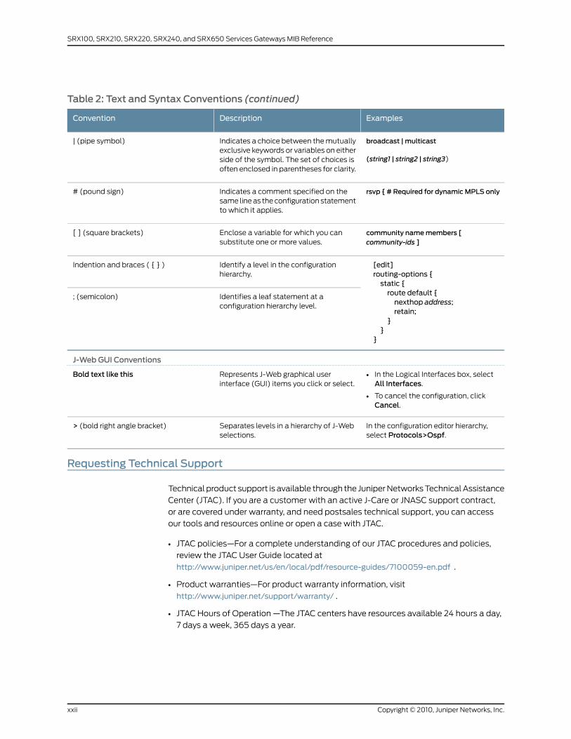
Table 2: Text and Syntax Conventions (continued)
ExamplesDescriptionConvention
broadcast | multicast
(string1 | string2 | string3)
Indicates a choice between the mutuallyexclusive keywords or variables on eitherside of the symbol. The set of choices isoften enclosed in parentheses for clarity.
| (pipe symbol)
rsvp { # Required for dynamicMPLS onlyIndicates a comment specified on thesame line as the configuration statementto which it applies.
# (pound sign)
community namemembers [community-ids ]
Enclose a variable for which you cansubstitute one or more values.
[ ] (square brackets)
[edit]routing-options {static {route default {nexthop address;retain;
}}
}
Identify a level in the configurationhierarchy.
Indention and braces ( { } )
Identifies a leaf statement at aconfiguration hierarchy level.
; (semicolon)
J-Web GUI Conventions
• In the Logical Interfaces box, selectAll Interfaces.
• To cancel the configuration, clickCancel.
Represents J-Web graphical userinterface (GUI) items you click or select.
Bold text like this
In the configuration editor hierarchy,select Protocols>Ospf.
Separates levels in a hierarchy of J-Webselections.
> (bold right angle bracket)
Requesting Technical Support
Technical product support is available through the Juniper Networks Technical Assistance
Center (JTAC). If you are a customer with an active J-Care or JNASC support contract,
or are covered under warranty, and need postsales technical support, you can access
our tools and resources online or open a case with JTAC.
• JTAC policies—For a complete understanding of our JTAC procedures and policies,
review the JTAC User Guide located at
http://www.juniper.net/us/en/local/pdf/resource-guides/7100059-en.pdf .
• Product warranties—For product warranty information, visit
http://www.juniper.net/support/warranty/ .
• JTAC Hours of Operation —The JTAC centers have resources available 24 hours a day,
7 days a week, 365 days a year.
Copyright © 2010, Juniper Networks, Inc.xxii
SRX100, SRX210, SRX220, SRX240, and SRX650 Services Gateways MIB Reference

Self-Help Online Tools and Resources
For quick and easy problem resolution, Juniper Networks has designed an online
self-service portal called the Customer Support Center (CSC) that provides you with the
following features:
• Find CSC offerings: http://www.juniper.net/customers/support/
• Find product documentation: http://www.juniper.net/techpubs/
• Find solutions and answer questions using our Knowledge Base: http://kb.juniper.net/
• Download the latest versions of software and review release notes:
http://www.juniper.net/customers/csc/software/
• Search technical bulletins for relevant hardware and software notifications:
https://www.juniper.net/alerts/
• Join and participate in the Juniper Networks Community Forum:
http://www.juniper.net/company/communities/
• Open a case online in the CSC Case Management tool: http://www.juniper.net/cm/
To verify service entitlement by product serial number, use our Serial Number Entitlement
(SNE) Tool: https://tools.juniper.net/SerialNumberEntitlementSearch/
Opening a Casewith JTAC
You can open a case with JTAC on the Web or by telephone.
• Use the Case Management tool in the CSC at http://www.juniper.net/cm/ .
• Call 1-888-314-JTAC (1-888-314-5822 toll-free in the USA, Canada, and Mexico).
For international or direct-dial options in countries without toll-free numbers, visit us at
http://www.juniper.net/support/requesting-support.html
xxiiiCopyright © 2010, Juniper Networks, Inc.
About This Guide

Copyright © 2010, Juniper Networks, Inc.xxiv
SRX100, SRX210, SRX220, SRX240, and SRX650 Services Gateways MIB Reference

PART 1
Network Management Introduction
• Network Management Overview on page 3
1Copyright © 2010, Juniper Networks, Inc.

Copyright © 2010, Juniper Networks, Inc.2
SRX100, SRX210, SRX220, SRX240, and SRX650 Services Gateways MIB Reference
CHAPTER 1
Network Management Overview
This chapter contains the following topic:
• Understanding Device Management Functions in Junos OS on page 3
Understanding DeviceManagement Functions in Junos OS
After you have installed a device into your network, you need to manage the device within
your network. Device management can be divided into five tasks:
• Fault management—Monitor the device; detect and fix faults.
• Configuration management—Configure device attributes.
• Accounting management—Collect statistics for accounting purposes.
• Performance management—Monitor and adjust device performance.
• Security management—Control device access and authenticate users.
The Junos OS network management features work in conjunction with an operations
support system (OSS) to manage the devices within the network. Junos OS can assist
you in performing these management tasks, as described in Table 3 on page 4.
3Copyright © 2010, Juniper Networks, Inc.
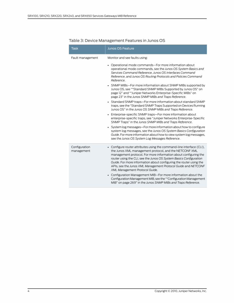
Table 3: Device Management Features in Junos OS
Junos OS FeatureTask
Monitor and see faults using:
• Operational mode commands—For more information aboutoperational mode commands, see the Junos OS System Basics andServices Command Reference, Junos OS Interfaces CommandReference, and Junos OS Routing Protocols and Policies CommandReference.
• SNMP MIBs—For more information about SNMP MIBs supported byJunos OS, see ““Standard SNMP MIBs Supported by Junos OS” onpage 12” and ““Juniper Networks Enterprise-Specific MIBs” onpage 23” in the Junos SNMPMIBs and Traps Reference.
• Standard SNMP traps—For more information about standard SNMPtraps, see the “Standard SNMP Traps Supported on Devices RunningJunos OS” in the Junos OS SNMPMIBs and Traps Reference.
• Enterprise-specific SNMP traps—For more information aboutenterprise-specific traps, see “Juniper Networks Enterprise-SpecificSNMP Traps” in the Junos SNMPMIBs and Traps Reference.
• System log messages—For more information about how to configuresystem log messages, see the Junos OS System Basics ConfigurationGuide. For more information about how to view system log messages,see the Junos OS System Log Messages Reference.
Fault management
• Configure router attributes using the command-line interface (CLI),the Junos XML management protocol, and the NETCONF XMLmanagement protocol. For more information about configuring therouter using the CLI, see the Junos OS System Basics ConfigurationGuide. For more information about configuring the router using theAPIs, see the Junos XML Management Protocol Guide and NETCONFXMLManagement Protocol Guide.
• Configuration Management MIB—For more information about theConfiguration Management MIB, see the ““Configuration ManagementMIB” on page 269” in the Junos SNMPMIBs and Traps Reference.
Configurationmanagement
Copyright © 2010, Juniper Networks, Inc.4
SRX100, SRX210, SRX220, SRX240, and SRX650 Services Gateways MIB Reference
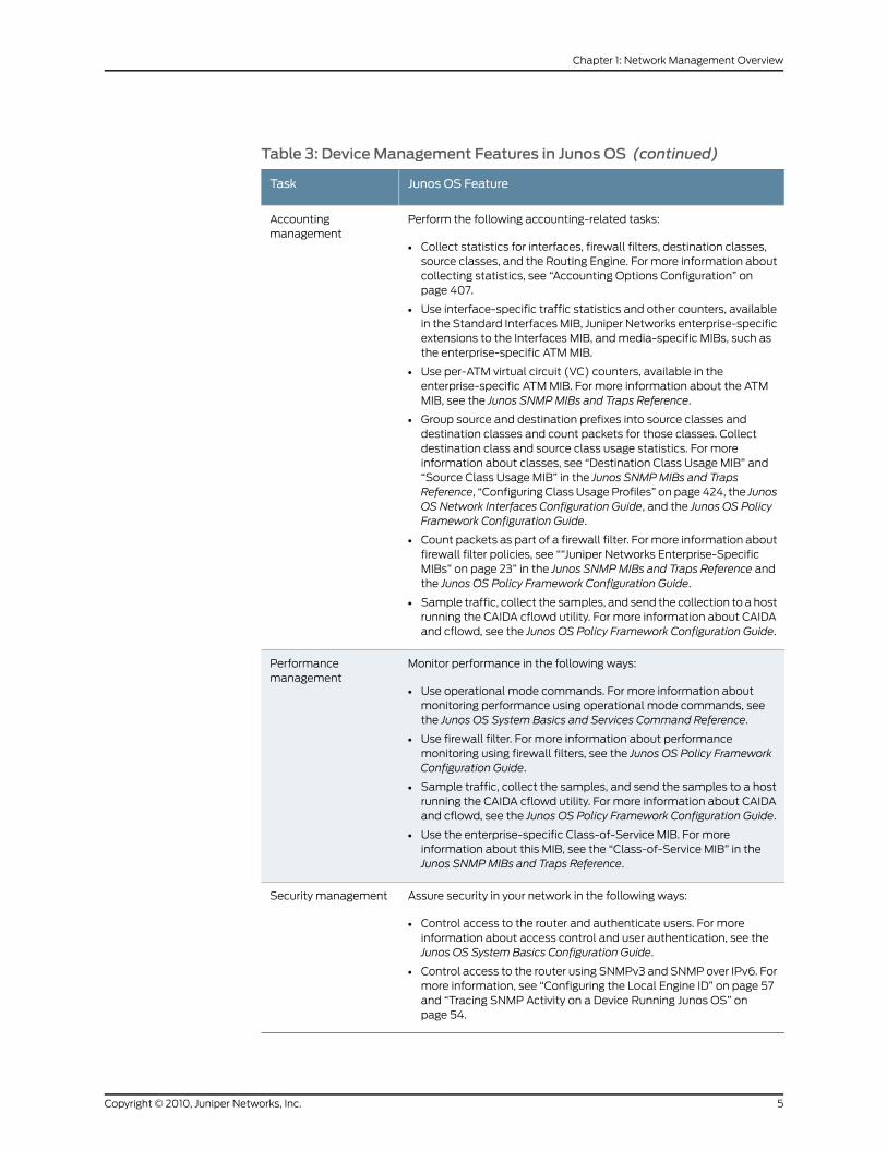
Table 3: Device Management Features in Junos OS (continued)
Junos OS FeatureTask
Perform the following accounting-related tasks:
• Collect statistics for interfaces, firewall filters, destination classes,source classes, and the Routing Engine. For more information aboutcollecting statistics, see “Accounting Options Configuration” onpage 407.
• Use interface-specific traffic statistics and other counters, availablein the Standard Interfaces MIB, Juniper Networks enterprise-specificextensions to the Interfaces MIB, and media-specific MIBs, such asthe enterprise-specific ATM MIB.
• Use per-ATM virtual circuit (VC) counters, available in theenterprise-specific ATM MIB. For more information about the ATMMIB, see the Junos SNMPMIBs and Traps Reference.
• Group source and destination prefixes into source classes anddestination classes and count packets for those classes. Collectdestination class and source class usage statistics. For moreinformation about classes, see “Destination Class Usage MIB” and“Source Class Usage MIB” in the Junos SNMPMIBs and TrapsReference, “Configuring Class Usage Profiles” on page 424, the JunosOS Network Interfaces Configuration Guide, and the Junos OS PolicyFramework Configuration Guide.
• Count packets as part of a firewall filter. For more information aboutfirewall filter policies, see ““Juniper Networks Enterprise-SpecificMIBs” on page 23” in the Junos SNMPMIBs and Traps Reference andthe Junos OS Policy Framework Configuration Guide.
• Sample traffic, collect the samples, and send the collection to a hostrunning the CAIDA cflowd utility. For more information about CAIDAand cflowd, see the Junos OS Policy Framework Configuration Guide.
Accountingmanagement
Monitor performance in the following ways:
• Use operational mode commands. For more information aboutmonitoring performance using operational mode commands, seethe Junos OS System Basics and Services Command Reference.
• Use firewall filter. For more information about performancemonitoring using firewall filters, see the Junos OS Policy FrameworkConfiguration Guide.
• Sample traffic, collect the samples, and send the samples to a hostrunning the CAIDA cflowd utility. For more information about CAIDAand cflowd, see the Junos OS Policy Framework Configuration Guide.
• Use the enterprise-specific Class-of-Service MIB. For moreinformation about this MIB, see the “Class-of-Service MIB” in theJunos SNMPMIBs and Traps Reference.
Performancemanagement
Assure security in your network in the following ways:
• Control access to the router and authenticate users. For moreinformation about access control and user authentication, see theJunos OS System Basics Configuration Guide.
• Control access to the router using SNMPv3 and SNMP over IPv6. Formore information, see “Configuring the Local Engine ID” on page 57and “Tracing SNMP Activity on a Device Running Junos OS” onpage 54.
Security management
5Copyright © 2010, Juniper Networks, Inc.
Chapter 1: Network Management Overview

RelatedDocumentation
• Understanding the Integrated Local Management Interface
• Understanding the SNMP Implementation in Junos OS on page 9
• Understanding Measurement Points, Key Performance Indicators, and Baseline Values
• Accounting Options Overview on page 405
Copyright © 2010, Juniper Networks, Inc.6
SRX100, SRX210, SRX220, SRX240, and SRX650 Services Gateways MIB Reference

PART 2
Simple Network Management Protocol(SNMP)
• SNMP Overview on page 9
• Configuring SNMP on page 37
• Standard SNMP Traps on page 59
• Juniper Networks Enterprise-Specific SNMP Traps on page 73
• Summary of SNMP Configuration Statements on page 93
• SNMP Remote Operations on page 115
• SNMP Support for Routing Instances on page 127
• SRX100, SRX210, SRX220, SRX240, and SRX650 Services Gateways Supported
Enterprise-Specific MIBs on page 145
7Copyright © 2010, Juniper Networks, Inc.

Copyright © 2010, Juniper Networks, Inc.8
SRX100, SRX210, SRX220, SRX240, and SRX650 Services Gateways MIB Reference

CHAPTER 2
SNMP Overview
This chapter contains the following topics:
• Understanding the SNMP Implementation in Junos OS on page 9
• Standard SNMP MIBs Supported by Junos OS on page 12
• Juniper Networks Enterprise-Specific MIBs on page 23
• Loading MIB Files to a Network Management System on page 35
Understanding the SNMP Implementation in Junos OS
SNMP enables the monitoring of network devices from a central location. This topic
provides an overview of SNMP and describes how SNMP is implemented in Junos OS.
This topic includes the following sections:
• SNMP Architecture on page 9
• Junos SNMP Agent Features on page 12
SNMPArchitecture
The SNMP agent exchanges network management information with SNMP manager
software running on a network management system (NMS), or host. The agent responds
to requests for information and actions from the manager. The agent also controls access
to the agent’s MIB, the collection of objects that can be viewed or changed by the SNMP
manager.
The SNMP manager collects information about network connectivity, activity, and events
by polling managed devices.
Communication between the agent and the manager occurs in one of the following
forms:
• Get,GetBulk, andGetNext requests—The manager requests information from the agent;
the agent returns the information in a Get response message.
• Set requests—The manager changes the value of a MIB object controlled by the agent;
the agent indicates status in a Set response message.
• Traps notification—The agent sends traps to notify the manager of significant events
that occur on the network device.
9Copyright © 2010, Juniper Networks, Inc.

This topic contains the following sections:
• Management Information Base (MIB) on page 10
• SNMP Traps and Informs on page 10
Management Information Base (MIB)
A MIB is a hierarchy of information used to define managed objects in a network device.
The MIB structure is based on a tree structure, which defines a grouping of objects into
related sets. Each object in the MIB is associated with an object identifier (OID), which
names the object. The “leaf” in the tree structure is the actual managed object instance,
which represents a resource, event, or activity that occurs in your network device.
MIBs are either standard or enterprise-specific. Standard MIBs are created by the Internet
Engineering Task Force (IETF) and documented in various RFCs. Depending on the vendor,
many standard MIBs are delivered with the NMS software. You can also download the
standard MIBs from the IETF website, www.ietf.org, and compile them into your NMS, if
necessary.
For a list of standard supported MIBs, see ““Standard SNMP MIBs Supported by Junos
OS” on page 12” in the Junos SNMPMIBs and Traps Reference.
Enterprise-specific MIBs are developed and supported by a specific equipment
manufacturer. If your network contains devices that have enterprise-specific MIBs, you
must obtain them from the manufacturer and compile them into your network
management software.
For a list of Juniper Networks enterprise-specific supported MIBs, see ““Juniper Networks
Enterprise-Specific MIBs” on page 23” in the Junos SNMPMIBs and Traps Reference.
SNMP Traps and Informs
Routers can send notifications to SNMP managers when significant events occur on a
network device, most often errors or failures. SNMP notifications can be sent as traps or
inform requests. SNMP traps are unconfirmed notifications. SNMP informs are confirmed
notifications.
SNMP traps are defined in either standard or enterprise-specific MIBs. Standard traps
are created by the IETF and documented in various RFCs. The standard traps are compiled
into the network management software. You can also download the standard traps from
the IETF website, www.ietf.org.
For more information about standard traps supported by Junos OS, see “Standard SNMP
Traps Supported on Devices Running Junos OS” in Junos OS SNMPMIBs and Traps
Reference.
Enterprise-specific traps are developed and supported by a specific equipment
manufacturer. If your network contains devices that have enterprise-specific traps, you
must obtain them from the manufacturer and compile them into your network
management software.
For more information about enterprise-specific traps supported by Junos OS, see “Juniper
Networks Enterprise-Specific SNMP Traps” in the Junos SNMPMIBs and Traps Reference.
Copyright © 2010, Juniper Networks, Inc.10
SRX100, SRX210, SRX220, SRX240, and SRX650 Services Gateways MIB Reference
For information about system logging severity levels for SNMP traps, see “System Logging
Severity Levels for SNMP Traps” on page 11.
With traps, the receiver does not send any acknowledgment when it receives a trap and
the sender cannot determine if the trap was received. To increase reliability, SNMP informs
are supported in SNMPv3. An SNMP manager that receives an inform acknowledges the
message with a response. For information about SNMP informs, see “Configuring SNMP
Informs” on page 90.
SNMP Trap Queuing
Junos OS supports trap queuing to ensure that traps are not lost because of temporary
unavailability of routes. Two types of queues, destination queues and a throttle queue,
are formed to ensure delivery of traps and control the trap traffic.
Junos OS forms a destination queue when a trap to a particular destination is returned
because the host is not reachable, and adds the subsequent traps to the same destination
to the queue. Junos OS checks for availability of routes every 30 seconds, and sends the
traps from the destination queue in a round-robin fashion. If the trap delivery fails, the
trap is added back to the queue, and the delivery attempt counter and the next delivery
attempt timer for the queue are reset. Subsequent attempts occur at progressive intervals
of 1 minute, 2 minutes, 4 minutes, and 8 minutes. The maximum delay between the
attempts is 8 minutes, and the maximum number of attempts is ten. After ten
unsuccessful attempts, the destination queue and all the traps in the queue are deleted.
Junos OS also has a throttle mechanism to control the number of traps (throttle threshold;
default value of 500 traps) sent during a particular time period (throttle interval; default
of 5 seconds) and to ensure consistency in trap traffic, especially when large number of
traps are generated because of interface status changes. The throttle interval period
begins when the first trap arrives at the throttle. All traps within the trap threshold are
processed, and the traps beyond the threshold limit are queued. The maximum size of
trap queues (that is, the throttle queue and the destination queue combined) is 40,000
traps; however, on EX Series switches, the maximum size of trap queue is 1000 traps
The maximum size of any one queue is 20,000 traps for devices other than EX Series
switches. On EX Series switches, the maximum size of one queue is 500 traps. If a trap
is sent from a destination queue when the throttle queue has exceeded the maximum
size, the trap is added back to the top of the destination queue, and all subsequent
attempts from the destination queue are stopped for a 30-second period, after which
the destination queue restarts sending the traps.
NOTE: Users cannot configure JunosOS for trap queuing. Users cannot viewany information about trap queues except what is available in the syslog.
System Logging Severity Levels for SNMP Traps
For some traps, when a trap condition occurs, regardless of whether the SNMP agent
sends a trap to an NMS, the trap is logged if the system logging is configured to log an
event with that system logging severity level. For more information about system logging
severity levels, see the Junos OS System Basics Configuration Guide.
11Copyright © 2010, Juniper Networks, Inc.
Chapter 2: SNMP Overview
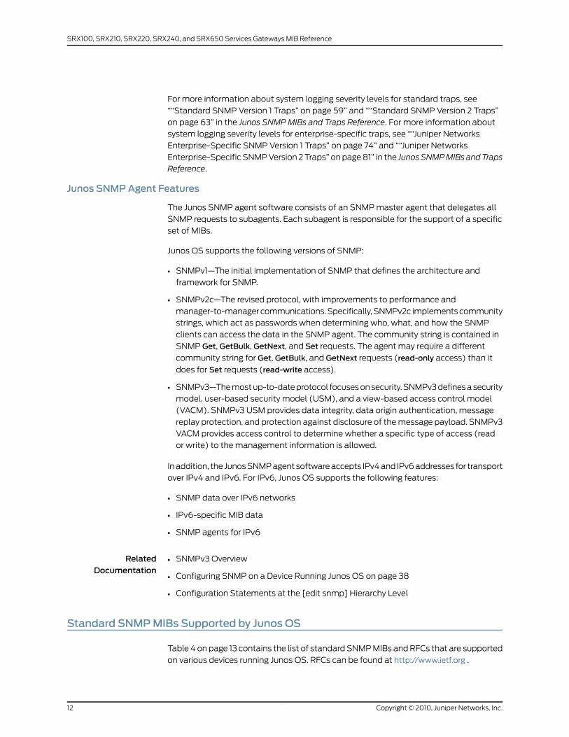
For more information about system logging severity levels for standard traps, see
““Standard SNMP Version 1 Traps” on page 59” and ““Standard SNMP Version 2 Traps”
on page 63” in the Junos SNMPMIBs and Traps Reference. For more information about
system logging severity levels for enterprise-specific traps, see ““Juniper Networks
Enterprise-Specific SNMP Version 1 Traps” on page 74” and ““Juniper Networks
Enterprise-Specific SNMP Version 2 Traps” on page 81” in the JunosSNMPMIBs andTraps
Reference.
Junos SNMPAgent Features
The Junos SNMP agent software consists of an SNMP master agent that delegates all
SNMP requests to subagents. Each subagent is responsible for the support of a specific
set of MIBs.
Junos OS supports the following versions of SNMP:
• SNMPv1—The initial implementation of SNMP that defines the architecture and
framework for SNMP.
• SNMPv2c—The revised protocol, with improvements to performance and
manager-to-manager communications. Specifically, SNMPv2c implements community
strings, which act as passwords when determining who, what, and how the SNMP
clients can access the data in the SNMP agent. The community string is contained in
SNMP Get, GetBulk, GetNext, and Set requests. The agent may require a different
community string for Get, GetBulk, and GetNext requests (read-only access) than it
does for Set requests (read-write access).
• SNMPv3—The most up-to-date protocol focuses on security. SNMPv3 defines a security
model, user-based security model (USM), and a view-based access control model
(VACM). SNMPv3 USM provides data integrity, data origin authentication, message
replay protection, and protection against disclosure of the message payload. SNMPv3
VACM provides access control to determine whether a specific type of access (read
or write) to the management information is allowed.
In addition, the Junos SNMP agent software accepts IPv4 and IPv6 addresses for transport
over IPv4 and IPv6. For IPv6, Junos OS supports the following features:
• SNMP data over IPv6 networks
• IPv6-specific MIB data
• SNMP agents for IPv6
RelatedDocumentation
SNMPv3 Overview•
• Configuring SNMP on a Device Running Junos OS on page 38
• Configuration Statements at the [edit snmp] Hierarchy Level
Standard SNMPMIBs Supported by Junos OS
Table 4 on page 13 contains the list of standard SNMP MIBs and RFCs that are supported
on various devices running Junos OS. RFCs can be found at http://www.ietf.org .
Copyright © 2010, Juniper Networks, Inc.12
SRX100, SRX210, SRX220, SRX240, and SRX650 Services Gateways MIB Reference
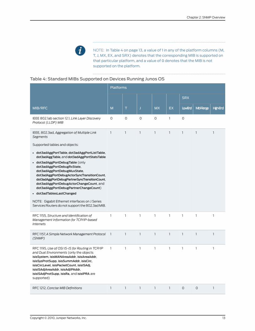
NOTE: In Table 4 on page 13, a value of 1 in any of the platform columns (M,
T, J, MX, EX, and SRX) denotes that the corresponding MIB is supported onthat particular platform, and a value of 0 denotes that the MIB is not
supported on the platform.
Table 4: StandardMIBs Supported on Devices Running Junos OS
Platforms
MIB/RFC
SRX
EXMXJTM High-EndMid-RangeLow-End
010000IEEE 802.1ab section 12.1, Link Layer DiscoveryProtocol (LLDP) MIB
11111111IEEE, 802.3ad, Aggregation of Multiple LinkSegments
Supported tables and objects:
• dot3adAggPortTable,dot3adAggPortListTable,dot3adAggTable, anddot3adAggPortStatsTable
• dot3adAggPortDebugTable (onlydot3adAggPortDebugRxState,dot3adAggPortDebugMuxState,dot3adAggPortDebugActorSyncTransitionCount,dot3adAggPortDebugPartnerSyncTransitionCount,dot3adAggPortDebugActorChangeCount, anddot3adAggPortDebugPartnerChangeCount)
• dot3adTablesLastChanged
NOTE: Gigabit Ethernet interfaces on J SeriesServices Routers do not support the 802.3ad MIB.
11111111RFC 1155, Structure and Identification ofManagement Information for TCP/IP-basedInternets
11111111RFC 1157,ASimpleNetworkManagementProtocol(SNMP)
11111111RFC 1195, Use of OSI IS-IS for Routing in TCP/IPand Dual Environments (only the objectsisisSystem, isisMANAreaAddr, isisAreaAddr,isisSysProtSupp, isisSummAddr, isisCirc,isisCircLevel, isisPacketCount, isisISAdj,isisISAdjAreaAddr, isisAdjIPAddr,isisISAdjProtSupp, isisRa, and isisIPRA aresupported)
10011111RFC 1212, Concise MIB Definitions
13Copyright © 2010, Juniper Networks, Inc.
Chapter 2: SNMP Overview
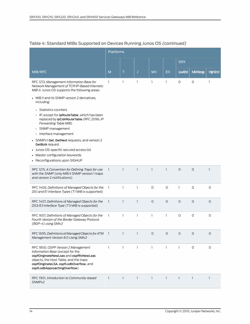
Table 4: StandardMIBs Supported on Devices Running Junos OS (continued)
Platforms
MIB/RFC
SRX
EXMXJTM High-EndMid-RangeLow-End
10011111RFC 1213, Management Information Base forNetworkManagement of TCP/IP-Based Internets:MIB-II. Junos OS supports the following areas:
• MIB II and its SNMP version 2 derivatives,including:
• Statistics counters
• IP, except for ipRouteTable, which has beenreplaced by ipCidrRouteTable (RFC 2096, IPForwarding Table MIB)
• SNMP management
• Interface management
• SNMPv1 Get, GetNext requests, and version 2GetBulk request
• Junos OS-specific secured access list
• Master configuration keywords
• Reconfigurations upon SIGHUP
10011111RFC 1215, A Convention for Defining Traps for usewith the SNMP (only MIB II SNMP version 1 trapsand version 2 notifications)
00100111RFC 1406, Definitions of Managed Objects for theDS1 and E1 Interface Types (T1 MIB is supported)
00000111RFC 1407, Definitions of Managed Objects for theDS3/E3 Interface Type (T3 MIB is supported)
00011111RFC 1657, Definitions of Managed Objects for theFourth Version of the Border Gateway Protocol(BGP-4) using SMIv2
00000111RFC 1695,DefinitionsofManagedObjects forATMManagement Version 8.0 Using SMIv2
00111111RFC 1850, OSPF Version 2 ManagementInformation Base (except for theospfOriginateNewLsas and ospfRxNewLsasobjects, the Host Table, and the trapsospfOriginateLSA, ospfLsdbOverflow, andospfLsdbApproachingOverflow)
11111111RFC 1901, Introduction to Community-basedSNMPv2
Copyright © 2010, Juniper Networks, Inc.14
SRX100, SRX210, SRX220, SRX240, and SRX650 Services Gateways MIB Reference
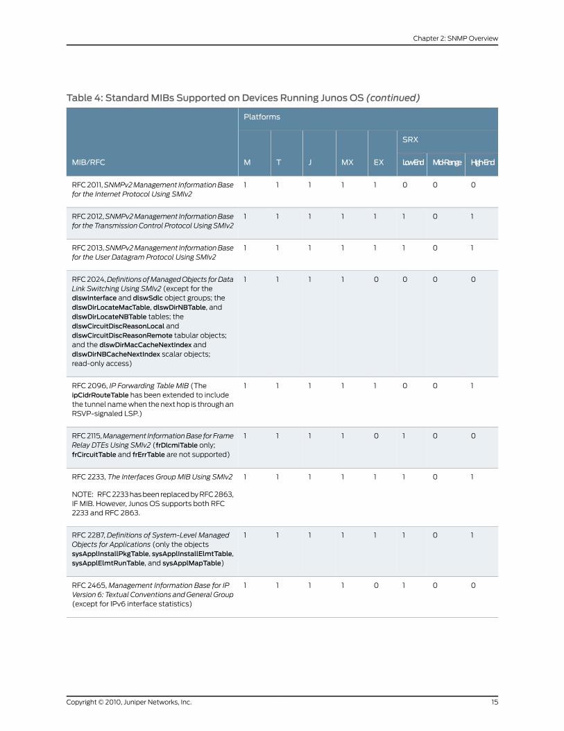
Table 4: StandardMIBs Supported on Devices Running Junos OS (continued)
Platforms
MIB/RFC
SRX
EXMXJTM High-EndMid-RangeLow-End
00011111RFC 2011,SNMPv2Management InformationBasefor the Internet Protocol Using SMIv2
10111111RFC 2012,SNMPv2Management InformationBasefor the TransmissionControl Protocol Using SMIv2
10111111RFC 2013,SNMPv2Management InformationBasefor the User Datagram Protocol Using SMIv2
00001111RFC 2024,DefinitionsofManagedObjects forDataLink Switching Using SMIv2 (except for thedlswInterface and dlswSdlc object groups; thedlswDirLocateMacTable, dlswDirNBTable, anddlswDirLocateNBTable tables; thedlswCircuitDiscReasonLocal anddlswCircuitDiscReasonRemote tabular objects;and the dlswDirMacCacheNextIndex anddlswDirNBCacheNextIndex scalar objects;read-only access)
10011111RFC 2096, IP Forwarding Table MIB (TheipCidrRouteTable has been extended to includethe tunnel name when the next hop is through anRSVP-signaled LSP.)
00101111RFC 2115,Management InformationBase forFrameRelay DTEs Using SMIv2 (frDlcmiTable only;frCircuitTable and frErrTable are not supported)
10111111RFC 2233, The Interfaces Group MIB Using SMIv2
NOTE: RFC 2233 has been replaced by RFC 2863,IF MIB. However, Junos OS supports both RFC2233 and RFC 2863.
10111111RFC 2287, Definitions of System-Level ManagedObjects for Applications (only the objectssysApplInstallPkgTable, sysApplInstallElmtTable,sysApplElmtRunTable, and sysApplMapTable)
00101111RFC 2465, Management Information Base for IPVersion6: Textual Conventions andGeneral Group(except for IPv6 interface statistics)
15Copyright © 2010, Juniper Networks, Inc.
Chapter 2: SNMP Overview
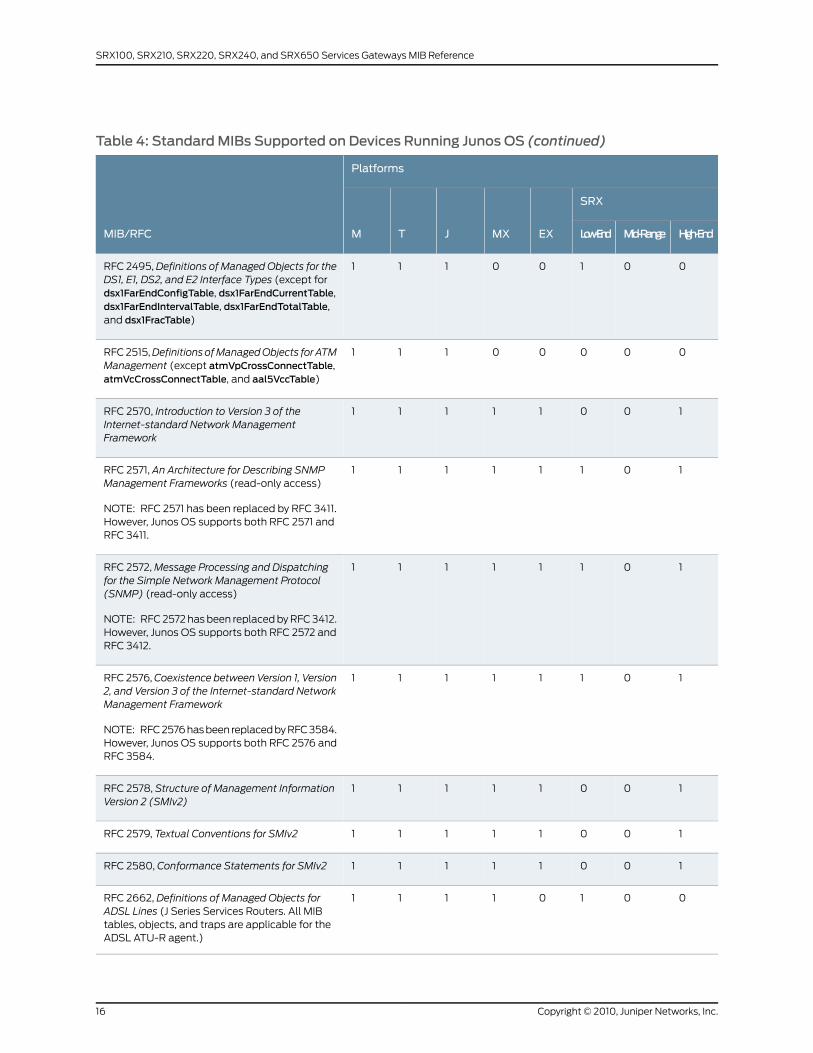
Table 4: StandardMIBs Supported on Devices Running Junos OS (continued)
Platforms
MIB/RFC
SRX
EXMXJTM High-EndMid-RangeLow-End
00100111RFC 2495, Definitions of Managed Objects for theDS1, E1, DS2, and E2 Interface Types (except fordsx1FarEndConfigTable, dsx1FarEndCurrentTable,dsx1FarEndIntervalTable, dsx1FarEndTotalTable,and dsx1FracTable)
00000111RFC 2515,Definitions ofManagedObjects for ATMManagement (except atmVpCrossConnectTable,atmVcCrossConnectTable, and aal5VccTable)
10011111RFC 2570, Introduction to Version 3 of theInternet-standard Network ManagementFramework
10111111RFC 2571, An Architecture for Describing SNMPManagement Frameworks (read-only access)
NOTE: RFC 2571 has been replaced by RFC 3411.However, Junos OS supports both RFC 2571 andRFC 3411.
10111111RFC 2572, Message Processing and Dispatchingfor the Simple Network Management Protocol(SNMP) (read-only access)
NOTE: RFC 2572 has been replaced by RFC 3412.However, Junos OS supports both RFC 2572 andRFC 3412.
10111111RFC 2576, Coexistence between Version 1, Version2, and Version 3 of the Internet-standard NetworkManagement Framework
NOTE: RFC 2576 has been replaced by RFC 3584.However, Junos OS supports both RFC 2576 andRFC 3584.
10011111RFC 2578, Structure of Management InformationVersion 2 (SMIv2)
10011111RFC 2579, Textual Conventions for SMIv2
10011111RFC 2580, Conformance Statements for SMIv2
00101111RFC 2662, Definitions of Managed Objects forADSL Lines (J Series Services Routers. All MIBtables, objects, and traps are applicable for theADSL ATU-R agent.)
Copyright © 2010, Juniper Networks, Inc.16
SRX100, SRX210, SRX220, SRX240, and SRX650 Services Gateways MIB Reference
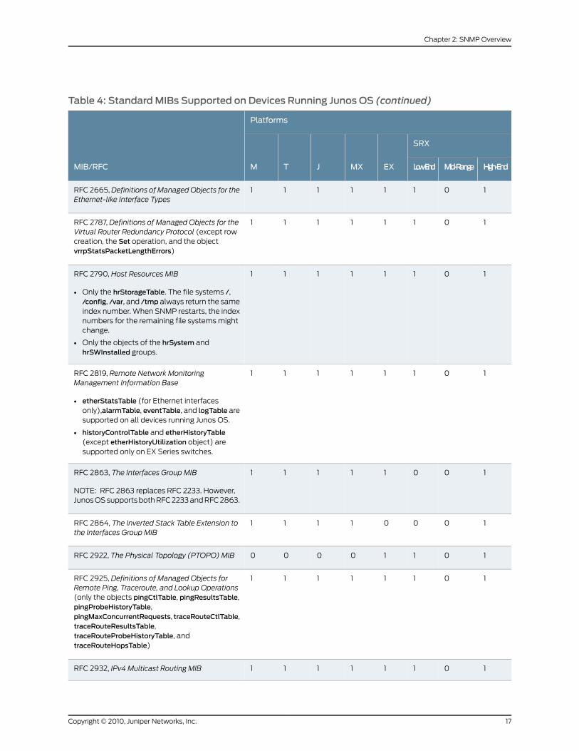
Table 4: StandardMIBs Supported on Devices Running Junos OS (continued)
Platforms
MIB/RFC
SRX
EXMXJTM High-EndMid-RangeLow-End
10111111RFC 2665, Definitions of ManagedObjects for theEthernet-like Interface Types
10111111RFC 2787, Definitions of Managed Objects for theVirtual Router Redundancy Protocol (except rowcreation, the Set operation, and the objectvrrpStatsPacketLengthErrors)
10111111RFC 2790, Host Resources MIB
• Only the hrStorageTable. The file systems /,/config, /var, and /tmp always return the sameindex number. When SNMP restarts, the indexnumbers for the remaining file systems mightchange.
• Only the objects of the hrSystem andhrSWInstalled groups.
10111111RFC 2819, Remote Network MonitoringManagement Information Base
• etherStatsTable (for Ethernet interfacesonly),alarmTable, eventTable, and logTable aresupported on all devices running Junos OS.
• historyControlTable and etherHistoryTable(except etherHistoryUtilization object) aresupported only on EX Series switches.
10011111RFC 2863, The Interfaces Group MIB
NOTE: RFC 2863 replaces RFC 2233. However,Junos OS supports both RFC 2233 and RFC 2863.
10001111RFC 2864, The Inverted Stack Table Extension tothe Interfaces Group MIB
10110000RFC 2922, The Physical Topology (PTOPO) MIB
10111111RFC 2925, Definitions of Managed Objects forRemote Ping, Traceroute, and Lookup Operations(only the objects pingCtlTable, pingResultsTable,pingProbeHistoryTable,pingMaxConcurrentRequests, traceRouteCtlTable,traceRouteResultsTable,traceRouteProbeHistoryTable, andtraceRouteHopsTable)
10111111RFC 2932, IPv4 Multicast Routing MIB
17Copyright © 2010, Juniper Networks, Inc.
Chapter 2: SNMP Overview
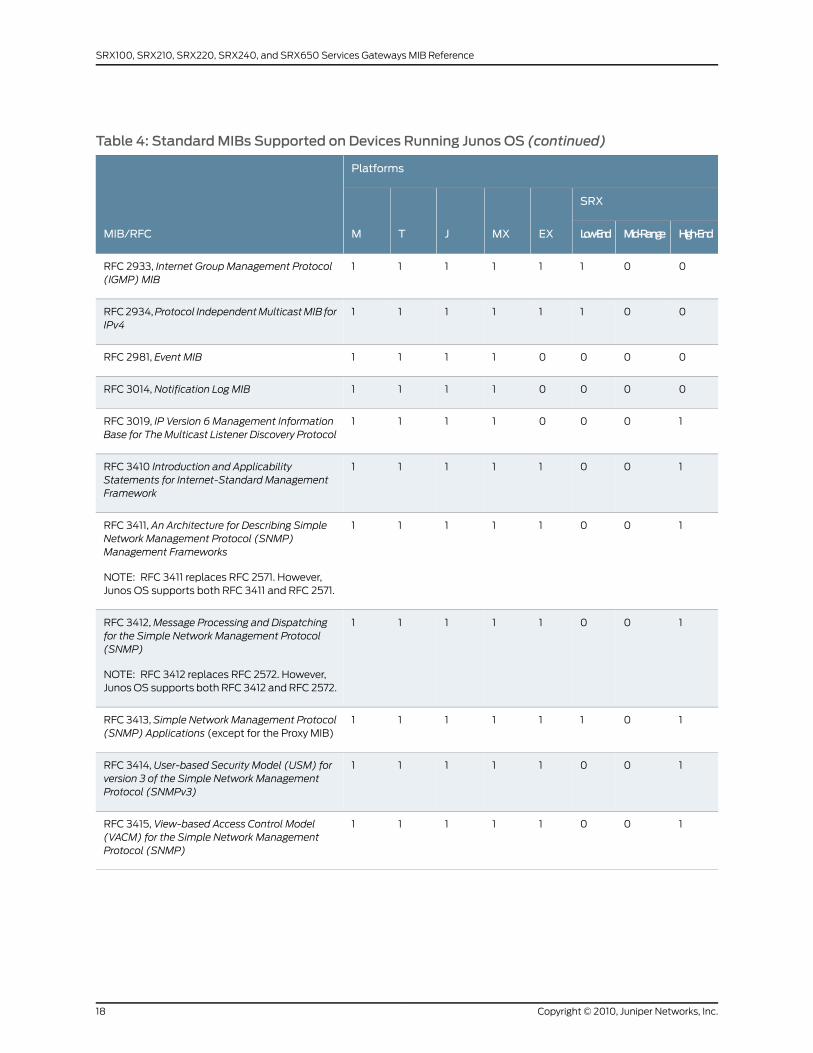
Table 4: StandardMIBs Supported on Devices Running Junos OS (continued)
Platforms
MIB/RFC
SRX
EXMXJTM High-EndMid-RangeLow-End
00111111RFC 2933, Internet Group Management Protocol(IGMP) MIB
00111111RFC 2934,Protocol IndependentMulticastMIB forIPv4
00001111RFC 2981, Event MIB
00001111RFC 3014, Notification Log MIB
10001111RFC 3019, IP Version 6 Management InformationBase for TheMulticast Listener Discovery Protocol
10011111RFC 3410 Introduction and ApplicabilityStatements for Internet-Standard ManagementFramework
10011111RFC 3411, An Architecture for Describing SimpleNetwork Management Protocol (SNMP)Management Frameworks
NOTE: RFC 3411 replaces RFC 2571. However,Junos OS supports both RFC 3411 and RFC 2571.
10011111RFC 3412, Message Processing and Dispatchingfor the Simple Network Management Protocol(SNMP)
NOTE: RFC 3412 replaces RFC 2572. However,Junos OS supports both RFC 3412 and RFC 2572.
10111111RFC 3413, Simple Network Management Protocol(SNMP) Applications (except for the Proxy MIB)
10011111RFC 3414, User-based Security Model (USM) forversion 3 of the Simple Network ManagementProtocol (SNMPv3)
10011111RFC 3415, View-based Access Control Model(VACM) for the Simple Network ManagementProtocol (SNMP)
Copyright © 2010, Juniper Networks, Inc.18
SRX100, SRX210, SRX220, SRX240, and SRX650 Services Gateways MIB Reference
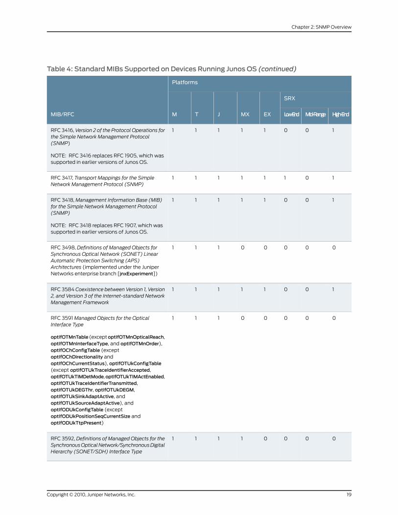
Table 4: StandardMIBs Supported on Devices Running Junos OS (continued)
Platforms
MIB/RFC
SRX
EXMXJTM High-EndMid-RangeLow-End
10011111RFC 3416, Version 2 of the Protocol Operations forthe Simple Network Management Protocol(SNMP)
NOTE: RFC 3416 replaces RFC 1905, which wassupported in earlier versions of Junos OS.
10111111RFC 3417, Transport Mappings for the SimpleNetwork Management Protocol (SNMP)
10011111RFC 3418, Management Information Base (MIB)for the Simple Network Management Protocol(SNMP)
NOTE: RFC 3418 replaces RFC 1907, which wassupported in earlier versions of Junos OS.
00000111RFC 3498, Definitions of Managed Objects forSynchronous Optical Network (SONET) LinearAutomatic Protection Switching (APS)Architectures (implemented under the JuniperNetworks enterprise branch [jnxExperiment])
10011111RFC 3584 Coexistence between Version 1, Version2, and Version 3 of the Internet-standard NetworkManagement Framework
00000111RFC 3591 Managed Objects for the OpticalInterface Type
optIfOTMnTable (exceptoptIfOTMnOpticalReach,optIfOTMnInterfaceType, and optIfOTMnOrder),optIfOChConfigTable (exceptoptIfOChDirectionality andoptIfOChCurrentStatus), optIfOTUkConfigTable(except optIfOTUkTraceIdentifierAccepted,optIfOTUkTIMDetMode,optIfOTUkTIMActEnabled,optIfOTUkTraceIdentifierTransmitted,optIfOTUkDEGThr, optIfOTUkDEGM,optIfOTUkSinkAdaptActive, andoptIfOTUkSourceAdaptActive), andoptIfODUkConfigTable (exceptoptIfODUkPositionSeqCurrentSize andoptIfODUkTtpPresent)
00001111RFC 3592, Definitions of Managed Objects for theSynchronousOpticalNetwork/SynchronousDigitalHierarchy (SONET/SDH) Interface Type
19Copyright © 2010, Juniper Networks, Inc.
Chapter 2: SNMP Overview

Table 4: StandardMIBs Supported on Devices Running Junos OS (continued)
Platforms
MIB/RFC
SRX
EXMXJTM High-EndMid-RangeLow-End
00010000RFC 3621, Power Ethernet MIB
00001111RFC 3637, Definitions of Managed Objects for theEthernet WAN Interface Sublayer (exceptetherWisDeviceTable,etherWisSectionCurrentTable, andetherWisFarEndPathCurrentTable)
00101111RFC 3811,DefinitionsofTextualConventions (TCs)for Multiprotocol Label Switching (MPLS)Management
00001111RFC 3812, Multiprotocol Label Switching (MPLS)Traffic Engineering (TE)Management InformationBase (MIB) (read only access)
• MPLS tunnels as interfaces are not supported.
• The following objects in the TunnelResourcetable are not supported:mplsTunnelResourceMeanRate,mplsTunnelResourceMaxBurstSize,mplsTunnelResourceMeanBurstSize,mplsTunnelResourceExBurstSize,mplsTunnelResourceWeight.
• mplsTunnelPerfTable andmplsTunnelCRLDPResTableare not supported.
• mplsTunnelCHopTable supported on ingressrouters only.
NOTE: The branch used by the proprietary LDPMIB (ldpmib.mib) conflicts with RFC 3812.ldpmib.mib has been deprecated and replacedby jnx-mpls-ldp.mib.
00101111RFC 3813, Multiprotocol Label Switching (MPLS)Label Switching Router (LSR) ManagementInformation Base (MIB) (read-only access)mplsInterfacePerfTable,mplsInSegmentPerfTable,mplsOutSegmentPerfTable,mplsInSegmentMapTable, mplsXCUp, andmplsXCDown are not supported.
00001111RFC 3815, Definitions of Managed Objects for theMultiprotocol Label Switching (MPLS), LabelDistribution Protocol (LDP) (only mplsLdpLsrIDand mplsLdpSesPeerAddrTable)
Copyright © 2010, Juniper Networks, Inc.20
SRX100, SRX210, SRX220, SRX240, and SRX650 Services Gateways MIB Reference
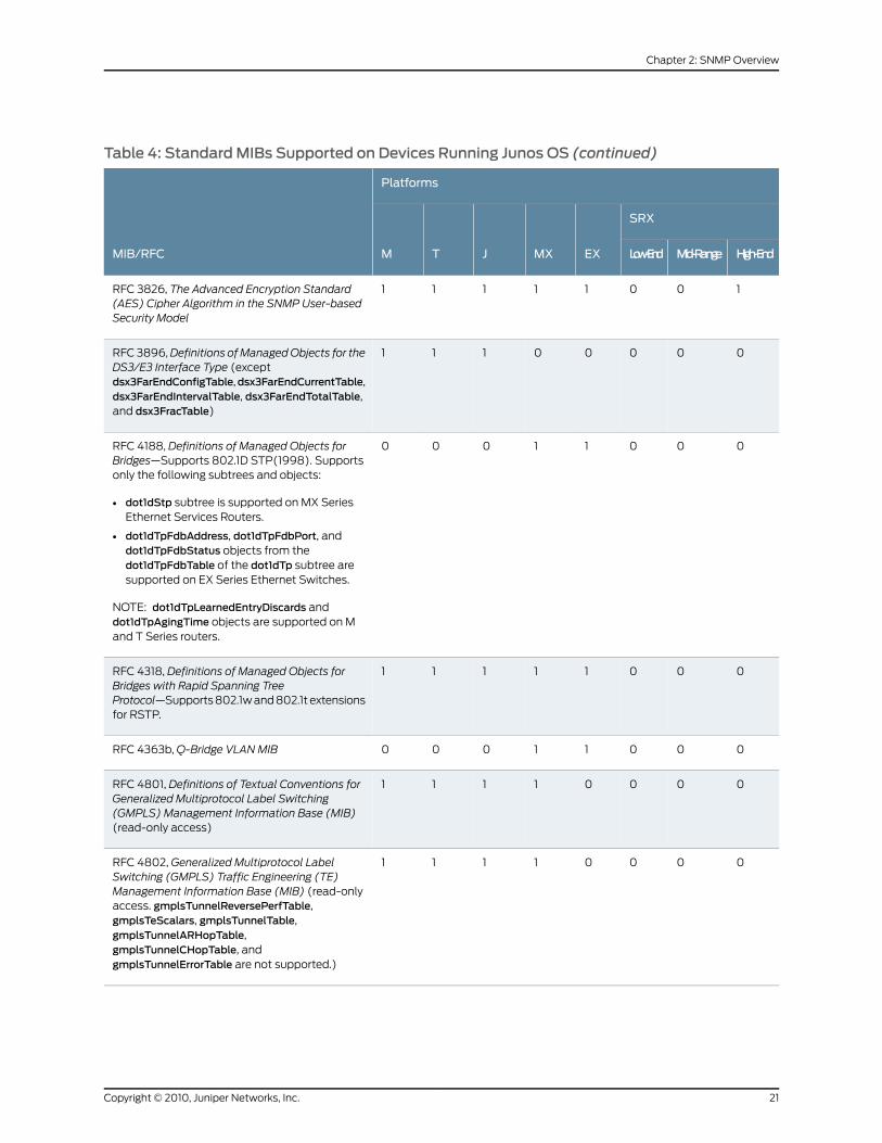
Table 4: StandardMIBs Supported on Devices Running Junos OS (continued)
Platforms
MIB/RFC
SRX
EXMXJTM High-EndMid-RangeLow-End
10011111RFC 3826, The Advanced Encryption Standard(AES) Cipher Algorithm in the SNMP User-basedSecurity Model
00000111RFC 3896,Definitions ofManagedObjects for theDS3/E3 Interface Type (exceptdsx3FarEndConfigTable,dsx3FarEndCurrentTable,dsx3FarEndIntervalTable, dsx3FarEndTotalTable,and dsx3FracTable)
00011000RFC 4188, Definitions of Managed Objects forBridges—Supports 802.1D STP(1998). Supportsonly the following subtrees and objects:
• dot1dStp subtree is supported on MX SeriesEthernet Services Routers.
• dot1dTpFdbAddress, dot1dTpFdbPort, anddot1dTpFdbStatus objects from thedot1dTpFdbTable of the dot1dTp subtree aresupported on EX Series Ethernet Switches.
NOTE: dot1dTpLearnedEntryDiscards anddot1dTpAgingTime objects are supported on Mand T Series routers.
00011111RFC 4318, Definitions of Managed Objects forBridges with Rapid Spanning TreeProtocol—Supports 802.1w and 802.1t extensionsfor RSTP.
00011000RFC 4363b, Q-Bridge VLANMIB
00001111RFC 4801, Definitions of Textual Conventions forGeneralized Multiprotocol Label Switching(GMPLS) Management Information Base (MIB)(read-only access)
00001111RFC 4802, Generalized Multiprotocol LabelSwitching (GMPLS) Traffic Engineering (TE)Management Information Base (MIB) (read-onlyaccess. gmplsTunnelReversePerfTable,gmplsTeScalars, gmplsTunnelTable,gmplsTunnelARHopTable,gmplsTunnelCHopTable, andgmplsTunnelErrorTable are not supported.)
21Copyright © 2010, Juniper Networks, Inc.
Chapter 2: SNMP Overview
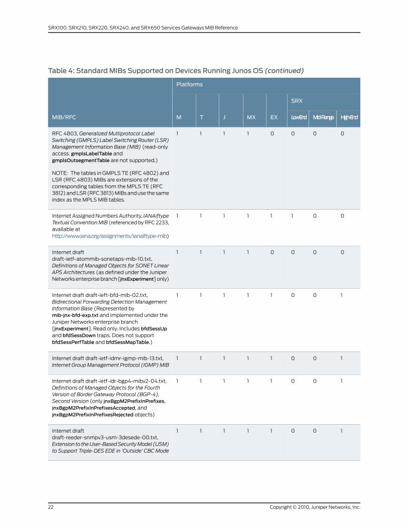
Table 4: StandardMIBs Supported on Devices Running Junos OS (continued)
Platforms
MIB/RFC
SRX
EXMXJTM High-EndMid-RangeLow-End
00001111RFC 4803, Generalized Multiprotocol LabelSwitching (GMPLS)LabelSwitchingRouter (LSR)Management Information Base (MIB) (read-onlyaccess. gmplsLabelTable andgmplsOutsegmentTable are not supported.)
NOTE: The tables in GMPLS TE (RFC 4802) andLSR (RFC 4803) MIBs are extensions of thecorresponding tables from the MPLS TE (RFC3812) and LSR (RFC 3813) MIBs and use the sameindex as the MPLS MIB tables.
00111111Internet Assigned Numbers Authority, IANAiftypeTextual ConventionMIB (referenced by RFC 2233,available athttp://www.iana.org/assignments/ianaiftype-mib)
00001111Internet draftdraft-ietf-atommib-sonetaps-mib-10.txt,Definitions of Managed Objects for SONET LinearAPS Architectures (as defined under the JuniperNetworks enterprise branch [jnxExperiment] only)
10011111Internet draft draft-ieft-bfd-mib-02.txt,Bidirectional Forwarding Detection ManagementInformation Base (Represented bymib-jnx-bfd-exp.txt and implemented under theJuniper Networks enterprise branch[jnxExperiment]. Read only. Includes bfdSessUpand bfdSessDown traps. Does not supportbfdSessPerfTable and bfdSessMapTable.)
10011111Internet draft draft-ietf-idmr-igmp-mib-13.txt,Internet GroupManagement Protocol (IGMP)MIB
10011111Internet draft draft-ietf-idr-bgp4-mibv2-04.txt,Definitions of Managed Objects for the FourthVersion of Border Gateway Protocol (BGP-4),Second Version (only jnxBgpM2PrefixInPrefixes,jnxBgpM2PrefixInPrefixesAccepted, andjnxBgpM2PrefixInPrefixesRejected objects)
10011111Internet draftdraft-reeder-snmpv3-usm-3desede-00.txt,Extension to theUser-BasedSecurityModel (USM)to Support Triple-DES EDE in ‘Outside’ CBCMode
Copyright © 2010, Juniper Networks, Inc.22
SRX100, SRX210, SRX220, SRX240, and SRX650 Services Gateways MIB Reference
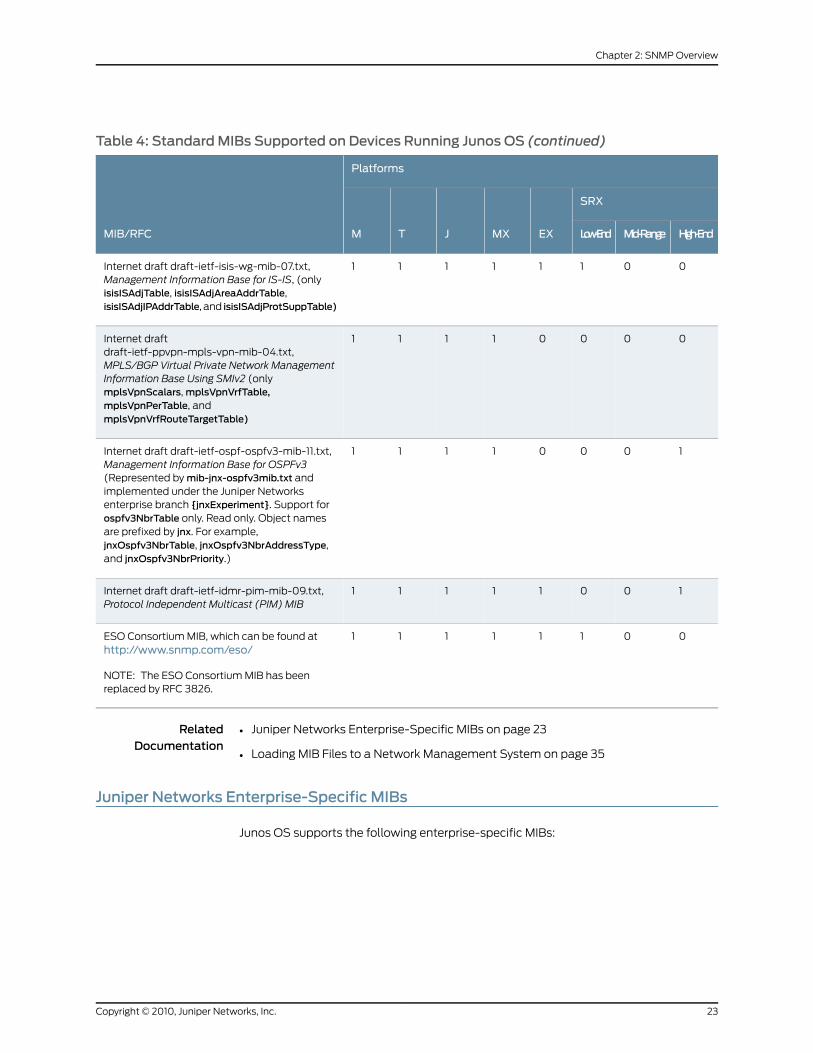
Table 4: StandardMIBs Supported on Devices Running Junos OS (continued)
Platforms
MIB/RFC
SRX
EXMXJTM High-EndMid-RangeLow-End
00111111Internet draft draft-ietf-isis-wg-mib-07.txt,Management Information Base for IS-IS, (onlyisisISAdjTable, isisISAdjAreaAddrTable,isisISAdjIPAddrTable, and isisISAdjProtSuppTable)
00001111Internet draftdraft-ietf-ppvpn-mpls-vpn-mib-04.txt,MPLS/BGP Virtual Private Network ManagementInformation Base Using SMIv2 (onlymplsVpnScalars, mplsVpnVrfTable,mplsVpnPerTable, andmplsVpnVrfRouteTargetTable)
10001111Internet draft draft-ietf-ospf-ospfv3-mib-11.txt,Management Information Base for OSPFv3(Represented by mib-jnx-ospfv3mib.txt andimplemented under the Juniper Networksenterprise branch {jnxExperiment}. Support forospfv3NbrTable only. Read only. Object namesare prefixed by jnx. For example,jnxOspfv3NbrTable, jnxOspfv3NbrAddressType,and jnxOspfv3NbrPriority.)
10011111Internet draft draft-ietf-idmr-pim-mib-09.txt,Protocol Independent Multicast (PIM) MIB
00111111ESO Consortium MIB, which can be found athttp://www.snmp.com/eso/
NOTE: The ESO Consortium MIB has beenreplaced by RFC 3826.
RelatedDocumentation
Juniper Networks Enterprise-Specific MIBs on page 23•
• Loading MIB Files to a Network Management System on page 35
Juniper Networks Enterprise-Specific MIBs
Junos OS supports the following enterprise-specific MIBs:
23Copyright © 2010, Juniper Networks, Inc.
Chapter 2: SNMP Overview

• AAA Objects MIB—Provides support for monitoring user authentication, authorization,
and accounting through the RADIUS, LDAP, SecurID, and local authentication servers.
This MIB is currently supported by Junos OS for J Series and SRX Series devices only.
For a downloadable version of this MIB, see
http://www.juniper.net/techpubs/en_US/junos10.4/topics/reference/mibs/mib-jnx-user-aaa.txt
.
For more information, see AAA Objects MIB.
• Access Authentication Objects MIB—Provides support for monitoring firewall
authentication, including data about the users trying to access firewall-protected
resources and the firewall authentication service itself. This MIB is currently supported
by Junos OS for J Series and SRX Series devices only. For a downloadable version of
this MIB, see
http://www.juniper.net/techpubs/en_US/junos10.4/topics/reference/mibs/mib-jnx-js-auth.txt
.
For more information, see “Access Authentication Objects MIB” on page 161.
• Alarm MIB—Provides support for alarms from the router. For a downloadable version
of this MIB, see
http://www.juniper.net/techpubs/en_US/junos10.4/topics/reference/mibs/mib-jnx-chassis-alarm.txt
.
For more information, see “Alarm MIB” on page 165.
• Analyzer MIB—Contains analyzer and remote analyzer data related to port mirroring
on the EX Series Ethernet Switches. For a downloadable version of this MIB, see
http://www.juniper.net/techpubs/en_US/junos10.4/topics/reference/mibs/mib-jnx-analyzer.txt
.
For more information, see Analyzer MIB.
• Antivirus Objects MIB—Provides information about the antivirus engine, antivirus scans,
and antivirus scan-related traps. For a downloadable version of this MIB, see
http://www.juniper.net/techpubs/en_US/junos10.4/topics/reference/mibs/mib-jnx-js-utm-av.txt
.
For more information, see Antivirus Objects MIB.
• ATM CoS MIB—Provides support for monitoring Asynchronous Transfer Mode, version
2 (ATM2) virtual circuit (VC) class-of-service (CoS) configurations. It also provides
CoS queue statistics for all VCs that have CoS configured. For a downloadable version
of this MIB, see
http://www.juniper.net/techpubs/en_US/junos10.4/topics/reference/mibs/mib-jnx-atm-cos.txt
.
For more information, see ATM Class-of-Service MIB.
• ATM MIB—Provides support for ATM interfaces and virtual connections. For a
downloadable version of this MIB, see
http://www.juniper.net/techpubs/en_US/junos10.4/topics/reference/mibs/mib-jnx-atm.txt
.
For more information, see ATM MIB.
Copyright © 2010, Juniper Networks, Inc.24
SRX100, SRX210, SRX220, SRX240, and SRX650 Services Gateways MIB Reference

• BFD MIB—Provides support for monitoring Bidirectional Forwarding Detection (BFD)
sessions. For a downloadable version of this MIB, see
http://www.juniper.net/techpubs/en_US/junos10.4/topics/reference/mibs/mib-jnx-bfd.txt
.
For more information, see “Bidirectional Forwarding Detection (BFD) MIB” on page 171.
• BGP4 V2 MIB—Contains objects used to monitor BGP peer-received prefix counters.
It is based upon similar objects in the MIB documented in Internet draft
draft-ietf-idr-bgp4-mibv2-03.txt,Definitions ofManagedObjects for the Fourth Version
of BGP (BGP-4), Second Version. For a downloadable version of this MIB, see
http://www.juniper.net/techpubs/en_US/junos10.4/topics/reference/mibs/mib-jnx-bgpmib2.txt
.
For more information, see “BGP4 V2 MIB” on page 169.
• Chassis MIB—Provides support for environmental monitoring (power supply state,
board voltages, fans, temperatures, and air flow) and inventory support for the chassis,
System Control Board (SCB), System and Switch Board (SSB), Switching and
Forwarding Module (SFM), Flexible PIC Concentrators (FPCs), and PICs. For a
downloadable version of this MIB, see
http://www.juniper.net/techpubs/en_US/junos10.4/topics/reference/mibs/mib-jnx-chassis.txt
.
For more information, see Chassis MIBs.
• Chassis Definitions for Router Model MIB—Contains the object identifiers (OIDs) that
are used by the Chassis MIB to identify platform and chassis components. The Chassis
MIB provides information that changes often, whereas the Chassis Definitions for Router
Model MIB provides information that changes less often. For a downloadable version
of this MIB, see
http://www.juniper.net/techpubs/en_US/junos10.4/topics/reference/mibs/mib-jnx-chas-defines.txt
.
For more information, see “BGP4 V2 MIB” on page 169.
• Chassis Forwarding MIB—Enables J Series Services Routers to fully support the Junos
OS health monitor. This MIB extends the scope of health monitoring to include Junos
forwarding process (fwdd) components. For a downloadable version of this MIB, see
http://www.juniper.net/techpubs/en_US/junos10.4/topics/reference/mibs/mib-jnx-chassis-fwdd.txt
.
For more information, see Chassis Forwarding MIB.
• Class-of-Service MIB—Provides support for monitoring interface output queue statistics
per interface and per forwarding class. For a downloadable version of this MIB, see
http://www.juniper.net/techpubs/en_US/junos10.4/topics/reference/mibs/mib-jnx-cos.txt
.
For more information, see Class-of-Service MIB.
• Configuration Management MIB—Provides notification for configuration changes as
SNMP traps. Each trap contains the time at which the configuration change was
committed, the name of the user who made the change, and the method by which the
change was made. A history of the last 32 configuration changes is kept in
25Copyright © 2010, Juniper Networks, Inc.
Chapter 2: SNMP Overview

jnxCmChgEventTable. For a downloadable version of this MIB, see
http://www.juniper.net/techpubs/en_US/junos10.4/topics/reference/mibs/mib-jnx-cfgmgmt.txt
.
For more information, see “Configuration Management MIB” on page 269.
• Digital Optical Monitoring MIB—Provides support for theSNMPGet request for statistics
and SNMP Trap notifications for alarms. For a downloadable version of this MIB, see
http://www.juniper.net/techpubs/en_US/junos10.4/topics/reference/mibs/mib-jnx-dom.txt
.
For more information, see Digital Optical Monitoring MIB.
• Destination Class Usage MIB—Provides support for monitoring packet counts based
on the ingress and egress points for traffic transiting your networks. Ingress points are
identified by input interface. Egress points are identified by destination prefixes grouped
into one or more sets, known as destination classes. One counter is managed per
interface per destination class, up to a maximum of 16 counters per interface. For a
downloadable version of this MIB, see
http://www.juniper.net/techpubs/en_US/junos10.4/topics/reference/mibs/mib-jnx-dcu.txt
.
For more information, see Destination Class Usage MIB.
• DNS Objects MIB—Provides support for monitoring DNS proxy queries, requests,
responses, and failures. This MIB is currently supported by Junos OS for J Series and
SRX Series devices only. For a downloadable version of this MIB, see
http://www.juniper.net/techpubs/en_US/junos10.4/topics/reference/mibs/mib-jnx-js-dns.txt
.
For more information, see DNS Objects MIB.
• Dynamic Flow Capture MIB—Provides support for monitoring the operational status
of dynamic flow capture PICs. For a downloadable version of this MIB, see
http://www.juniper.net/techpubs/en_US/junos10.4/topics/reference/mibs/mib-jnx-dfc.txt
.
For more information, see Dynamic Flow Capture MIB.
• Ethernet MAC MIB—Monitors media access control (MAC) statistics on Gigabit Ethernet
intelligent queuing (IQ) interfaces. It collects MAC statistics; for example, inoctets,
inframes,outoctets, andoutframeson each source MAC address and virtual LAN (VLAN)
ID for each Ethernet port. For a downloadable version of this MIB, see
http://www.juniper.net/techpubs/en_US/junos10.4/topics/reference/mibs/jnx-mac.txt
.
For more information, see “Ethernet MAC MIB” on page 275.
• Event MIB—Defines a generic trap that can be generated using an op script or event
policy. This MIB provides the ability to specify a system log string and raise a trap if
that system log string is found. For a downloadable version of this MIB, see
http://www.juniper.net/techpubs/en_US/junos10.4/topics/reference/mibs/mib-jnx-event.txt
.
For more information, see “Event MIB” on page 277.
Copyright © 2010, Juniper Networks, Inc.26
SRX100, SRX210, SRX220, SRX240, and SRX650 Services Gateways MIB Reference

• Experimental MIB—Contains object identifiers for experimental MIBs. For a
downloadable version of this MIB, see
http://www.juniper.net/techpubs/en_US/junos10.4/topics/reference/mibs/mib-jnx-exp.txt
.
For more information, see “jnxExperiment” on page 158.
• Firewall MIB—Provides support for monitoring firewall filter counters. Routers must
have the Internet Processor II ASIC to perform firewall monitoring. For a downloadable
version of this MIB, see
http://www.juniper.net/techpubs/en_US/junos10.4/topics/reference/mibs/mib-jnx-firewall.txt
.
For more information, see “Firewall MIB” on page 279.
• Flow Collection Services MIB—Provides statistics on files, records, memory, FTP, and
error states of a monitoring services interface. It also provides SNMP traps for
unavailable destinations, unsuccessful file transfers, flow overloading, and memory
overloading. For a downloadable version of this MIB, see
http://www.juniper.net/techpubs/en_US/junos10.4/topics/reference/mibs/mib-jnx-coll.txt
.
For more information, see Flow Collection Services MIB.
• Host Resources MIB—Extends the hrStorageTable object, providing a measure of the
usage of each file system on the router in percentage. Previously, the objects in the
hrStorageTable measured the usage in allocation units—hrStorageUsed and
hrStorageAllocationUnits—only. Using the percentage measurement, you can more
easily monitor and apply thresholds on usage. For a downloadable version of this MIB,
see
http://www.juniper.net/techpubs/en_US/junos10.4/topics/reference/mibs/mib-jnx-hostresources.txt
.
For more information, see “Host Resources MIB” on page 283.
• SNMP IDP Objects MIB—Provides support for monitoring SNMP IDP queries, requests,
responses, and failures. This MIB defines the key monitoring and threshold crossing
trap support, IDP database update status and trap support, attack-related monitoring
and trap support for SRX100, SRX210, SRX220, SRX240, and SRX650 Services
Gateways. This MIB models IDP attributes specific to the appropriate Juniper Networks
implementation. For a downloadable version of this MIB, see
http://www.juniper.net/techpubs/en_US/junos10.4/topics/reference/mibs/mib-jnx-js-idp.txt.
For more information, see “IDP MIB” on page 387.
• Interface MIB—Extends the standard ifTable (RFC 2863) with additional statistics and
Juniper Networks enterprise-specific chassis information. For a downloadable version
of this MIB, see
http://www.juniper.net/techpubs/en_US/junos10.4/topics/reference/mibs/mib-jnx-if-extensions.txt
.
For more information, see “Interface MIB” on page 285.
• IP Forward MIB—Extends the standard IP Forwarding Table MIB (RFC 2096) to include
CIDR forwarding information. For a downloadable version of this MIB, see
27Copyright © 2010, Juniper Networks, Inc.
Chapter 2: SNMP Overview

http://www.juniper.net/techpubs/en_US/junos10.4/topics/reference/mibs/mib-jnx-ipforward.txt
.
For more information, see “IP Forward MIB” on page 291.
• IPsec Monitoring MIB—Provides operational and statistical information related to the
IPsec and IKE tunnels on Juniper Networks routers. For a downloadable version of this
MIB, see
http://www.juniper.net/techpubs/en_US/junos10.4/topics/reference/mibs/mib-jnx-ipsec-monitor.txt
.
For more information, see “IPSec Monitoring MIB” on page 309.
• IPsec Generic Flow Monitoring Object MIB—Based on jnx-ipsec-monitor-mib, this MIB
provides support for monitoring IPsec and IPsec VPN management objects. This MIB
is currently supported by Junos OS for J Series and SRX Series devices only. For a
downloadable version of this MIB, see
http://www.juniper.net/techpubs/en_US/junos10.4/topics/reference/mibs/mib-jnx-ipsec-flow-mon.txt
.
For more information, see “IPsec Generic Flow Monitoring Object MIB” on page 293.
• IPsec VPN Objects MIB—Provides support for monitoring IPsec and IPsec VPN
management objects for Juniper security product lines. This MIB is an extension of
jnx-ipsec-flow-mon.mib. This MIB is currently supported by Junos OS for J Series and
SRX Series devices only. For a downloadable version of this MIB, see
http://www.juniper.net/techpubs/en_US/junos10.4/topics/reference/mibs/mib-jnx-js-ipsec-vpn.txt
.
For more information, see IPsec VPN Objects MIB.
• IPv4 MIB—Provides additional Internet Protocol version 4 (IPv4) address information,
supporting the assignment of identical IPv4 addresses to separate interfaces. For a
downloadable version of this MIB, see
http://www.juniper.net/techpubs/en_US/junos10.4/topics/reference/mibs/mib-jnx-ipv4.txt
.
For more information, see “IPv4 MIB” on page 317.
• IPv6 and ICMPv6 MIB—Provides IPv6 and Internet Control Message Protocol version
6 (ICMPv6) statistics. For a downloadable version of this MIB, see
http://www.juniper.net/techpubs/en_US/junos10.4/topics/reference/mibs/mib-jnx-ipv6.txt
. For more information, see “IPv6 MIB Overview” on page 319.
• L2ALD MIB—Contains information about Layer 2 Address Learning Daemon and related
traps, such as the routing instance MAC limit trap and the interface MAC limit trap. For
a downloadable version of this MIB, see
http://www.juniper.net/techpubs/en_US/junos10.4/topics/reference/mibs/mib-jnx-l2ald.txt
.
For more information, see L2ALD MIB.
• L2CP Features MIB—Provides information about Layer 2 Control Protocols-based
features on MX Series Ethernet Services Routers. Currently, Junos OS supports only
the jnxDot1dStpPortRootProtectEnabled, jnxDot1dStpPortRootProtectState, and
jnxPortRootProtectStateChangeTrap objects. For a downloadable version of this MIB,
Copyright © 2010, Juniper Networks, Inc.28
SRX100, SRX210, SRX220, SRX240, and SRX650 Services Gateways MIB Reference
see
http://www.juniper.net/techpubs/en_US/junos10.4/topics/reference/mibs/mib-jnx-l2cp-features.txt
.
For more information, see Layer 2 Control Protocol (L2CP) MIB.
• L2TP MIB—Provides information about Layer 2 Transport Protocol (L2TP) tunnels and
sessions. For a downloadable version of this MIB, see
http://www.juniper.net/techpubs/en_US/junos10.4/topics/reference/mibs/mib-jnx-l2tp.txt
.
For more information, see Layer 2 Transport Protocol (L2TP) MIB.
• LDP MIB—Provides LDP statistics and defines LDP label-switched path (LSP)
notifications. LDP traps support only IPv4 standards. For a downloadable version of
this MIB, see
http://www.juniper.net/techpubs/en_US/junos10.4/topics/reference/mibs/mib-jnx-ldp.txt
.
For more information, see LDP MIB.
• Multiple Instance Multiple Spanning Tree Protocol (MIMSTP) MIB—Provides information
about MSTP instances (that is, routing instances of type Virtual Switch/Layer 2 control,
also known as virtual contexts), MSTIs within the MSTP instance, and VLANs associated
with the MSTI. For a downloadable version of this MIB, see
http://www.juniper.net/techpubs/en_US/junos10.4/topics/reference/mibs/mib-jnx-mimstp.txt
.
For more information, see MIMSTP MIB.
• MPLS MIB—Provides MPLS information and defines MPLS notifications. For a
downloadable version of this MIB, see
http://www.juniper.net/techpubs/en_US/junos10.4/topics/reference/mibs/mib-jnx-mpls.txt
.
NOTE: To collect information aboutMPLS statistics on transit routers, usethe enterprise-specific RSVPMIB (mib-jnx-rsvp.txt) instead of the
enterprise-specific MPLSMIB (mib-jnx-mpls.txt).
For more information, see MPLSMIB.
• MPLS LDP MIB—Contains object definitions as described in RFC 3815, Definitions of
Managed Objects for the Multiprotocol Label Switching (MPLS), Label Distribution
Protocol (LDP). For a downloadable version of this MIB, see
http://www.juniper.net/techpubs/en_US/junos10.4/topics/reference/mibs/mib-jnx-mpls-ldp.txt
.
29Copyright © 2010, Juniper Networks, Inc.
Chapter 2: SNMP Overview
NOTE: Objects in the MPLS LDPMIB were supported in earlier releases ofJunos OS as a proprietary LDPMIB (mib-ldpmib.txt). Because the branch
used by the proprietary LDP (mib-ldpmib.txt) conflicts with RFC 3812, the
proprietary LDPMIB (mib-ldpmib.txt) has been deprecated and replaced
by the enterprise-specific MPLS LDPMIB (mib-jnx-mpls-ldp.txt).
For more information, see MPLS LDPMIB.
• Network Address Translation (NAT) Objects MIB—Provides support for monitoring
network address translation (NAT). This MIB is currently supported by Junos OS for J
Series and SRX Series devices only. For a downloadable version of this MIB, see
http://www.juniper.net/techpubs/en_US/junos10.4/topics/reference/mibs/mib-jnx-js-nat.txt
.
For more information, see “Network Address Translation Objects MIB” on page 327.
• Optical Transport Network (OTN) MIB—Defines objects for managing OTN interfaces
on devices running Junos OS. For a downloadable version of the MIB, see
http://www.juniper.net/techpubs/en_US/junos10.4/topics/reference/mibs/mib-jnx-otn.txt
.
For more information, see OTN Interface Management MIB.
• Packet Forwarding Engine MIB—Provides notification statistics for Packet Forwarding
Engines. For a downloadable version of this MIB, see
http://www.juniper.net/techpubs/en_US/junos10.4/topics/reference/mibs/mib-jnx-pfe.txt
.
For more information, see “Packet Forwarding Engine MIB” on page 335.
• PAE Extension MIB—Extends the standard IEEE802.1x PAE Extension MIB, and contains
information for Static MAC Authentication. The enterprise-specific PAE Extension MIB
is supported only on EX Series Ethernet Switches. For a downloadable version of this
MIB, see
http://www.juniper.net/techpubs/en_US/junos10.4/topics/reference/mibs/mib-jnx-pae-extension.txt
.
For more information, see PAE Extension MIB.
• Passive Monitoring MIB—Performs traffic flow monitoring and lawful interception of
packets transiting between two routers. For a downloadable version of this MIB, see
http://www.juniper.net/techpubs/en_US/junos10.4/topics/reference/mibs/mib-jnx-pmon.txt
.
For more information, see Passive Monitoring MIB.
• Ping MIB—Extends the standard Ping MIB control table (RFC 2925). Items in this MIB
are created when entries are created in pingCtlTable of the Ping MIB. Each item is
indexed exactly as it is in the Ping MIB. For a downloadable version of this MIB, see
http://www.juniper.net/techpubs/en_US/junos10.4/topics/reference/mibs/mib-jnx-ping.txt
.
For more information, see “PING MIB” on page 339.
Copyright © 2010, Juniper Networks, Inc.30
SRX100, SRX210, SRX220, SRX240, and SRX650 Services Gateways MIB Reference

• Policy Objects MIB—Provides support for monitoring the security policies that control
the flow of traffic from one zone to another. This MIB is currently supported by Junos
OS for J Series and SRX Series devices only. For a downloadable version of this MIB,
see
http://www.juniper.net/techpubs/en_US/junos10.4/topics/reference/mibs/mib-jnx-js-policy.txt
.
For more information, see “Policy Objects MIB” on page 355.
• Power Supply Unit MIB—Enables monitoring and managing of power supply on a device
running Junos OS. This MIB is currently supported only on EX Series Ethernet Switches.
For a downloadable version of this MIB, see For a downloadable version of this MIB,
see
http://www.juniper.net/techpubs/en_US/junos10.4/topics/reference/mibs/mib-jnx-power-supply-unit.txt
.
For more information, see Power Supply Unit MIB.
• Pseudowire TDM MIB—Extends the standard Pseudowire MIB, and contains information
about configuration and statistics for specific pseudowire types. The enterprise-specific
Pseudowire TDM MIB is the Juniper Networks implementation of the standard Managed
Objects for TDM over Packet Switched Network MIB (draft-ietf-pwe3-tdm-mib-08.txt).
For a downloadable version of this MIB, see
http://www.juniper.net/techpubs/en_US/junos10.4/topics/reference/mibs/mib-jnx-pwtdm.txt
.
• Real-Time Media MIB—Defines a Real-Time Media configuration. For a downloadable
version of this MIB, see
http://www.juniper.net/techpubs/en_US/junos10.4/information-products/
topic-collections/reference-mibs-and-traps/jnx-rtm.txt .
For more information, see “Real-Time Media MIB Overview” on page 361.
• Real-time Performance Monitoring Protocol (RPM) MIB—Provides real-time
performance-related data and enables you to access jitter measurements and
calculations using SNMP. For a downloadable version of this MIB, see
http://www.juniper.net/techpubs/en_US/junos10.4/topics/reference/mibs/mib-jnx-rpm.txt
.
For more information, see Real-Time Performance Monitoring (RPM) MIB.
• Reverse-Path-Forwarding MIB—Monitors statistics for traffic that is rejected because
of reverse-path-forwarding (RPF) processing. For a downloadable version of this MIB,
see
http://www.juniper.net/techpubs/en_US/junos10.4/topics/reference/mibs/mib-jnx-rpf.txt
.
NOTE: The enterprise-specific RPFMIB is not supported on EX SeriesEthernet Switches.
For more information, see “Reverse Path Forwarding MIB” on page 371.
31Copyright © 2010, Juniper Networks, Inc.
Chapter 2: SNMP Overview
• RSVP traffic engineering (TE) MIB—Provides information about RSVP-traffic engineering
sessions that correspond to MPLS LSPs on transit routers in the service provider core
network. For a downloadable version of this MIB, see
http://www.juniper.net/techpubs/en_US/junos10.4/topics/reference/mibs/mib-jnx-rsvp.txt
.
NOTE: To collect information aboutMPLS statistics on transit routers, usethe enterprise-specific RSVPMIB (mib-jnx-rsvp.txt) instead of the
enterprise-specific MPLSMIB (mib-jnx-mpls.txt).
For more information, see RSVPMIB.
• RMON Events and Alarms MIB—Supports the Junos extensions to the standard Remote
Monitoring (RMON) Events and Alarms MIB (RFC 2819). The extension augments
alarmTable with additional information about each alarm. Two new traps are also
defined to indicate when problems are encountered with an alarm. For a downloadable
version of this MIB, see
http://www.juniper.net/techpubs/en_US/junos10.4/topics/reference/mibs/mib-jnx-rmon.txt
.
For more information, see “RMON Events and Alarms MIB” on page 373.
• Security Interface Extension Objects MIB—Provides support for the security
management of interfaces. This MIB is currently supported by Junos OS for J Series
and SRX Series devices only. For a downloadable version of this MIB, see
http://www.juniper.net/techpubs/en_US/junos10.4/topics/reference/mibs/mib-jnx-js-if-ext.txt
.
For more information, see “Security Interface Extension Objects MIB” on page 377.
• Security Screening Objects MIB—Defines the MIB for the Juniper Networks Enterprise
Firewall screen functionality. This MIB is currently supported by Junos OS for J Series
and SRX Series devices only. For a downloadable version of this MIB, see
http://www.juniper.net/techpubs/en_US/junos10.4/topics/reference/mibs/mib-jnx-js-screening.txt
.
For more information, see Security Screening Objects MIB.
• Services PIC MIB—Provides statistics for Adaptive Services (AS) PICs and defines
notifications for AS PICs. For a downloadable version of this MIB, see
http://www.juniper.net/techpubs/en_US/junos10.4/topics/reference/mibs/mib-jnx-sp.txt
.
For more information, see Services PIC MIB.
• SIP Common MIB—Defines objects that are common to all SIP entities. For a
downloadable version of this MIB, see
http://www.juniper.net/techpubs/en_US/junos10.4/information-products/
topic-collections/reference-mibs-and-traps/jnx-sipcommon.txt.
For more information, see “SIP Common MIB Overview” on page 381.
Copyright © 2010, Juniper Networks, Inc.32
SRX100, SRX210, SRX220, SRX240, and SRX650 Services Gateways MIB Reference

• SONET/SDH Interface Management MIB—Monitors the current alarm for each
SONET/SDH interface. For a downloadable version of this MIB, see
http://www.juniper.net/techpubs/en_US/junos10.4/topics/reference/mibs/mib-jnx-sonet.txt
.
For more information, see SONET/SDH Interface Management MIB.
• SONET Automatic Protection Switching MIB—Monitors any SONET interface that
participates in Automatic Protection Switching (APS). For a downloadable version of
this MIB, see
http://www.juniper.net/techpubs/en_US/junos10.4/topics/reference/mibs/mib-jnx-sonetaps.txt
.
For more information, see SONET APS MIB.
• Source Class Usage MIB—Counts packets sent to customers by performing a lookup
on the IP source address and the IP destination address. The Source Class Usage (SCU)
MIB makes it possible to track traffic originating from specific prefixes on the provider
core and destined for specific prefixes on the customer edge. For a downloadable
version of this MIB, see
http://www.juniper.net/techpubs/en_US/junos10.4/topics/reference/mibs/mib-jnx-scu.txt
.
For more information, see Source Class Usage MIB.
• SPU Monitoring MIB—Provides support for monitoring SPUs on SRX5600 and SRX5800
devices. For a downloadable version of this MIB, see
http://www.juniper.net/techpubs/en_US/junos10.4/topics/reference/mibs/mib-jnx-js-spu-monitoring.txt
.
For more information, see SPU Monitoring MIB.
• Structure of Management Information MIB—Explains how the Juniper Networks
enterprise-specific MIBs are structured. For a downloadable version of this MIB, see
http://www.juniper.net/techpubs/en_US/junos10.4/topics/reference/mibs/mib-jnx-smi.txt
.
For more information, see “Structure of Management Information MIB” on page 153.
• Structure of Management Information MIB for EX Series Ethernet Switches—Defines
a MIB branch for switching-related MIB definitions for the EX Series Ethernet switches.
For a downloadable version of this MIB, see
http://www.juniper.net/techpubs/en_US/junos10.4/topics/reference/mibs/mib-jnx-ex-smi.txt
.
For more information, see EX Series SMI MIB.
• Structure of Management Information MIB—Contains object identifiers (OIDs) for the
security branch of the MIBs used in Junos OS for J Series and SRX Series devices,
services and traps. This MIB is currently supported by Junos OS for J Series and SRX
Series devices only. For a downloadable version of this MIB, see
http://www.juniper.net/techpubs/en_US/junos10.4/topics/reference/mibs/mib-jnx-js-smi.txt
• System Log MIB—Enables notification of an SNMP trap-based application when an
important system log message occurs. For a downloadable version of this MIB, see
33Copyright © 2010, Juniper Networks, Inc.
Chapter 2: SNMP Overview

http://www.juniper.net/techpubs/en_US/junos10.4/topics/reference/mibs/mib-jnx-syslog.txt
.
For more information, see “System Log MIB” on page 389.
• Traceroute MIB—Supports the Junos extensions of traceroute and remote operations.
Items in this MIB are created when entries are created in the traceRouteCtlTable of
the Traceroute MIB. Each item is indexed exactly the same way as it is in the Traceroute
MIB. For a downloadable version of this MIB, see
http://www.juniper.net/techpubs/en_US/junos10.4/topics/reference/mibs/mib-jnx-traceroute.txt
.
For more information, see “Traceroute MIB” on page 393.
• Utility MIB—Provides SNMP support for exposing Junos data and has tables that contain
information about each type of data, such as integer and string. For a downloadable
version of this MIB, see
http://www.juniper.net/techpubs/en_US/junos10.4/topics/reference/mibs/mib-jnx-util.txt
.
For more information, see “Utility MIB” on page 395.
• Virtual Chassis MIB—Contains information about virtual chassis on EX Series Ethernet
Switches. For a downloadable version of this MIB, see
http://www.juniper.net/techpubs/en_US/junos10.4/topics/reference/mibs/mib-jnx-virtualchassis.txt
.
For more information, see Virtual Chassis MIB.
• VLAN MIB—Contains information about prestandard IEEE 802.10 VLANs and their
association with LAN emulation clients. The enterprise-specific VLAN MIB is supported
only on EX Series Ethernet Switches. For a downloadable version of this MIB, see
http://www.juniper.net/techpubs/en_US/junos10.4/topics/reference/mibs/mib-jnx-vlan.txt
.
For more information, see VLAN MIB.
• VPN MIB—Provides monitoring for Layer 3 VPNs, Layer 2 VPNs, and virtual private LAN
service (VPLS) (read access only). For a downloadable version of the MIB, see
http://www.juniper.net/techpubs/en_US/junos10.4/topics/reference/mibs/mib-jnx-vpn.txt
.
For more information, see VPN MIB.
• VPN Certificate Objects MIB—Provides support for monitoring the local and CA
certificates loaded on the router. This MIB is currently supported by Junos OS for J
Series and SRX Series devices only. For a downloadable version of this MIB, see
http://www.juniper.net/techpubs/en_US/junos10.4/topics/reference/mibs/mib-jnx-js-cert.txt
.
For more information, see “VPN Certificate Objects MIB” on page 399.
RelatedDocumentation
Standard SNMP MIBs Supported by Junos OS on page 12•
• Loading MIB Files to a Network Management System on page 35
Copyright © 2010, Juniper Networks, Inc.34
SRX100, SRX210, SRX220, SRX240, and SRX650 Services Gateways MIB Reference

LoadingMIB Files to a Network Management System
For your network management system (NMS) to identify and understand the MIB objects
used by Junos OS, you must first load the MIB files to your NMS using a MIB compiler. A
MIB compiler is a utility that parses the MIB information such as MIB object name, IDs,
and data type for the NMS.
You can download the Junos MIB package from the Enterprise-Specific MIBs and Traps
section of the Junos OS Technical Publications index page at
http://www.juniper.net/techpubs/software/junos/index.html. The Junos MIB package is
available in .zip and .tar packages; you can download the appropriate format based on
your requirements.
The Junos MIB package contains two folders, namelyStandardMibsand JuniperMibs. The
StandardMibs folder contains the standard MIBs and RFCs that are supported on devices
running Junos OS, whereas the JuniperMibs folder contains the Juniper Networks
enterprise-specific MIBs.
To load MIB files that are required for managing and monitoring devices running Junos
OS:
1. Go to the Junos OS Technical Publications index page
(http://www.juniper.net/techpubs/software/junos/index.html).
2. Click the tab that corresponds to the Junos OS Release for which you want to download
the MIB files.
3. On the selected tab, click the+ (plus) sign that corresponds to the Enterprise-Specific
MIBs and Traps section to expand the section.
4. Click the TAR or ZIP link that corresponds to the Enterprise MIBs link under the
Enterprise-Specific MIBs and Traps section to download the Junos MIB package.
5. Decompress the file (.tar or .zip) using an appropriate utility.
6. Load the standard MIB files (from the StandardMibs folder) in the following order:
NOTE: Some of the MIB compilers that are commonly used have thestandardMIBspreloadedon them. If thestandardMIBsarealready loadedon the MIB compiler that you are using, skip this step and the next, andproceed to Step 7.
a. mib-SNMPv2-SMI.txt
b. mib-SNMPv2-TC.txt
c. mib-IANAifType-MIB.txt
d. mib-IANA-RTPROTO-MIB.txt
e. mib-rfc1907.txt
35Copyright © 2010, Juniper Networks, Inc.
Chapter 2: SNMP Overview
f. mib-rfc2011a.txt
g. mib-rfc2012a.txt
h. mib-rfc2013a.txt
i. mib-rfc2863a.txt
7. Load the remaining standard MIB files.
NOTE: Youmust follow the order specified in this procedure, and ensurethat all standard MIBs are loaded before you load the enterprise-specificMIBs. Theremay be dependencies that require a particular MIB to bepresent on the compiler before loading someotherMIB. You can find suchdependencies listed in the IMPORT section of the MIB file.
8. After loading the standard MIBs, load the Juniper Networks enterprise-specific SMI
MIB,mib-jnx-smi.txtand the following optional SMI MIBs based on your requirements.
• mib-jnx-js-smi.txt—(Optional) For Juniper Security MIB tree objects
• mib-jnx-ex-smi.txt—(Optional) For EX Series Ethernet Switches
• mib-jnx-exp.txt—(Recommended) For Juniper Networks experimental MIB objects
9. Load the remaining enterprise-specific MIBs from the JuniperMibs folder.
TIP: While loading aMIB file, if the compiler returns an errormessage sayingthat any of the objects is undefined, open theMIB file using a text editor andensure that all the MIB files listed in the IMPORT section are loaded on the
compiler. If any of the MIB files listed in the IMPORT section is not loaded on
the compiler, load that MIB file, and then try to load the MIB file that failedto load.
For example, the enterprise-specific PINGMIB,mib-jnx-ping.txt, has
dependencies on RFC 2925, DiSMAN-PING-MIB,mib-rfc2925a.txt. If you try
to loadmib-jnx-ping.txtbefore loadingmib-rfc2925a.txt, the compiler returns
anerrormessagesaying that certainobjects inmib-jnx-ping.txtareundefined.
Loadmib-rfc2925a.txt, and then try to loadmib-jnx-ping.txt. The
enterprise-specific PINGMIB,mib-jnx-ping.txt, then loads without any issue.
RelatedDocumentation
• Standard SNMP MIBs Supported by Junos OS on page 12
• Juniper Networks Enterprise-Specific MIBs on page 23
Copyright © 2010, Juniper Networks, Inc.36
SRX100, SRX210, SRX220, SRX240, and SRX650 Services Gateways MIB Reference

CHAPTER 3
Configuring SNMP
This chapter contains the following topics:
• Configuring SNMP on a Device Running Junos OS on page 38
• Configuring the System Contact on a Device Running Junos OS on page 40
• Configuring the System Location for a Device Running Junos OS on page 40
• Configuring the System Description on a Device Running Junos OS on page 41
• Filtering Duplicate SNMP Requests on page 41
• Configuring the Commit Delay Timer on page 42
• Configuring the System Name on page 42
• Configuring the SNMP Community String on page 43
• Adding a Group of Clients to an SNMP Community on page 44
• Configuring SNMP Trap Options and Groups on a Device Running Junos OS on page 45
• Configuring SNMP Trap Options on page 46
• Configuring SNMP Trap Groups on page 49
• Spoofing Enterprise-Specific SNMP Traps on page 51
• Configuring the Interfaces on Which SNMP Requests Can Be Accepted on page 52
• Filtering Interface Information Out of SNMP Get and GetNext Output on page 52
• Configuring MIB Views on page 53
• Tracing SNMP Activity on a Device Running Junos OS on page 54
• Configuring the Local Engine ID on page 57
37Copyright © 2010, Juniper Networks, Inc.
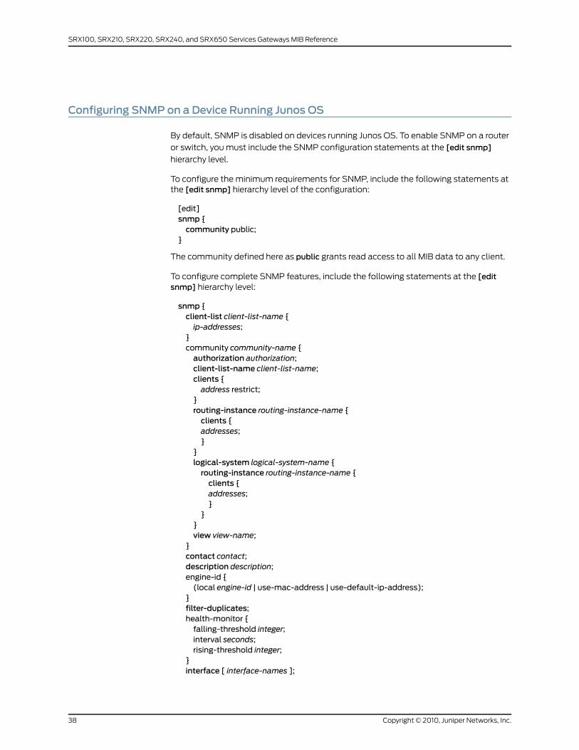
Configuring SNMP on a Device Running Junos OS
By default, SNMP is disabled on devices running Junos OS. To enable SNMP on a router
or switch, you must include the SNMP configuration statements at the [edit snmp]
hierarchy level.
To configure the minimum requirements for SNMP, include the following statements atthe [edit snmp] hierarchy level of the configuration:
[edit]snmp {community public;
}
The community defined here as public grants read access to all MIB data to any client.
To configure complete SNMP features, include the following statements at the [editsnmp] hierarchy level:
snmp {client-list client-list-name {ip-addresses;
}community community-name {authorization authorization;client-list-name client-list-name;clients {address restrict;
}routing-instance routing-instance-name {clients {addresses;}
}logical-system logical-system-name {routing-instance routing-instance-name {clients {addresses;}
}}view view-name;
}contact contact;description description;engine-id {(local engine-id | use-mac-address | use-default-ip-address);
}filter-duplicates;health-monitor {falling-threshold integer;interval seconds;rising-threshold integer;
}interface [ interface-names ];
Copyright © 2010, Juniper Networks, Inc.38
SRX100, SRX210, SRX220, SRX240, and SRX650 Services Gateways MIB Reference
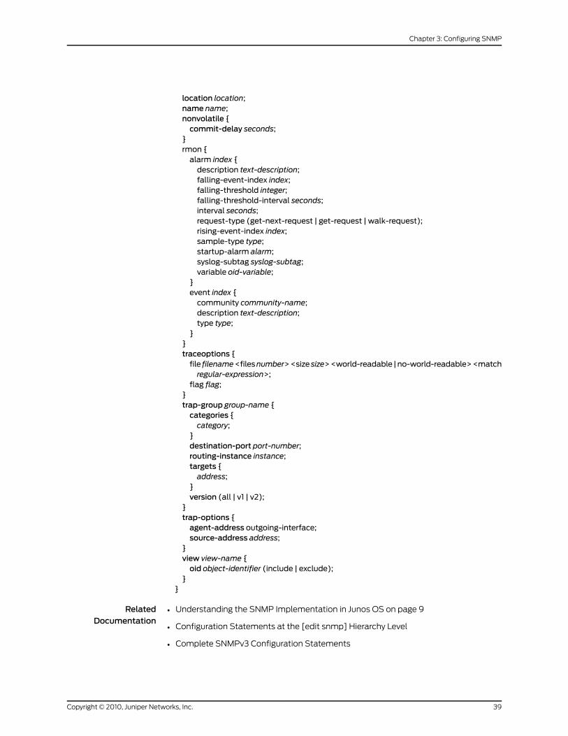
location location;name name;nonvolatile {commit-delay seconds;
}rmon {alarm index {description text-description;falling-event-index index;falling-threshold integer;falling-threshold-interval seconds;interval seconds;request-type (get-next-request | get-request | walk-request);rising-event-index index;sample-type type;startup-alarm alarm;syslog-subtag syslog-subtag;variable oid-variable;
}event index {community community-name;description text-description;type type;
}}traceoptions {file filename<filesnumber><size size><world-readable |no-world-readable><matchregular-expression>;
flag flag;}trap-group group-name {categories {category;
}destination-port port-number;routing-instance instance;targets {address;
}version (all | v1 | v2);
}trap-options {agent-address outgoing-interface;source-address address;
}view view-name {oid object-identifier (include | exclude);
}}
RelatedDocumentation
Understanding the SNMP Implementation in Junos OS on page 9•
• Configuration Statements at the [edit snmp] Hierarchy Level
• Complete SNMPv3 Configuration Statements
39Copyright © 2010, Juniper Networks, Inc.
Chapter 3: Configuring SNMP
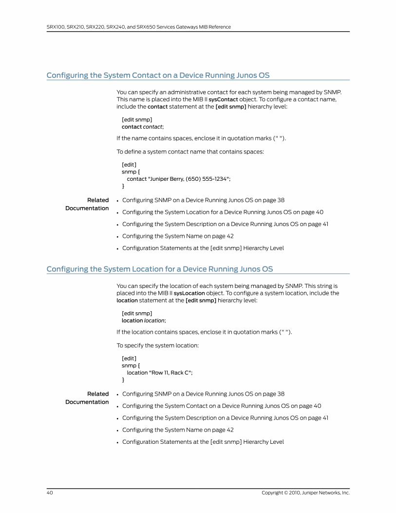
Configuring the SystemContact on a Device Running Junos OS
You can specify an administrative contact for each system being managed by SNMP.This name is placed into the MIB II sysContact object. To configure a contact name,include the contact statement at the [edit snmp] hierarchy level:
[edit snmp]contact contact;
If the name contains spaces, enclose it in quotation marks (" ").
To define a system contact name that contains spaces:
[edit]snmp {contact "Juniper Berry, (650) 555-1234";
}
RelatedDocumentation
Configuring SNMP on a Device Running Junos OS on page 38•
• Configuring the System Location for a Device Running Junos OS on page 40
• Configuring the System Description on a Device Running Junos OS on page 41
• Configuring the System Name on page 42
• Configuration Statements at the [edit snmp] Hierarchy Level
Configuring the System Location for a Device Running Junos OS
You can specify the location of each system being managed by SNMP. This string isplaced into the MIB II sysLocation object. To configure a system location, include thelocation statement at the [edit snmp] hierarchy level:
[edit snmp]location location;
If the location contains spaces, enclose it in quotation marks (" ").
To specify the system location:
[edit]snmp {location "Row 11, Rack C";
}
RelatedDocumentation
Configuring SNMP on a Device Running Junos OS on page 38•
• Configuring the System Contact on a Device Running Junos OS on page 40
• Configuring the System Description on a Device Running Junos OS on page 41
• Configuring the System Name on page 42
• Configuration Statements at the [edit snmp] Hierarchy Level
Copyright © 2010, Juniper Networks, Inc.40
SRX100, SRX210, SRX220, SRX240, and SRX650 Services Gateways MIB Reference
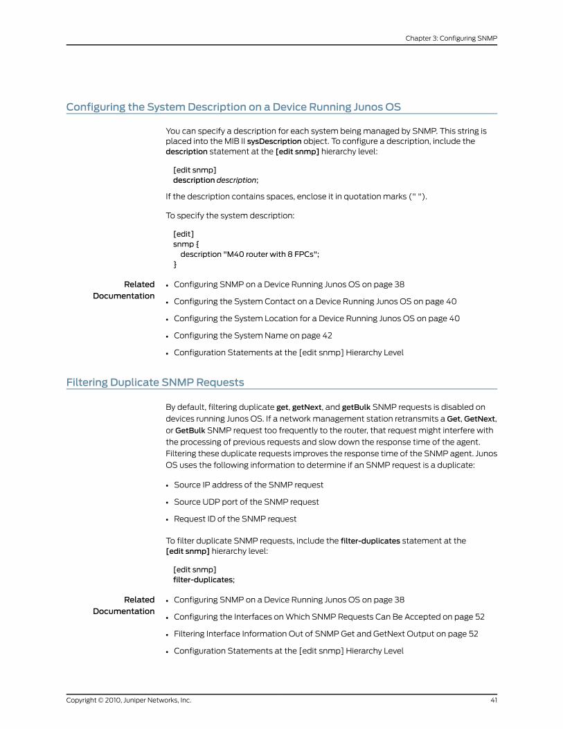
Configuring the SystemDescription on a Device Running Junos OS
You can specify a description for each system being managed by SNMP. This string isplaced into the MIB II sysDescription object. To configure a description, include thedescription statement at the [edit snmp] hierarchy level:
[edit snmp]description description;
If the description contains spaces, enclose it in quotation marks (" ").
To specify the system description:
[edit]snmp {description "M40 router with 8 FPCs";
}
RelatedDocumentation
Configuring SNMP on a Device Running Junos OS on page 38•
• Configuring the System Contact on a Device Running Junos OS on page 40
• Configuring the System Location for a Device Running Junos OS on page 40
• Configuring the System Name on page 42
• Configuration Statements at the [edit snmp] Hierarchy Level
Filtering Duplicate SNMPRequests
By default, filtering duplicate get, getNext, and getBulk SNMP requests is disabled on
devices running Junos OS. If a network management station retransmits a Get, GetNext,
or GetBulk SNMP request too frequently to the router, that request might interfere with
the processing of previous requests and slow down the response time of the agent.
Filtering these duplicate requests improves the response time of the SNMP agent. Junos
OS uses the following information to determine if an SNMP request is a duplicate:
• Source IP address of the SNMP request
• Source UDP port of the SNMP request
• Request ID of the SNMP request
To filter duplicate SNMP requests, include the filter-duplicates statement at the[edit snmp] hierarchy level:
[edit snmp]filter-duplicates;
RelatedDocumentation
Configuring SNMP on a Device Running Junos OS on page 38•
• Configuring the Interfaces on Which SNMP Requests Can Be Accepted on page 52
• Filtering Interface Information Out of SNMP Get and GetNext Output on page 52
• Configuration Statements at the [edit snmp] Hierarchy Level
41Copyright © 2010, Juniper Networks, Inc.
Chapter 3: Configuring SNMP
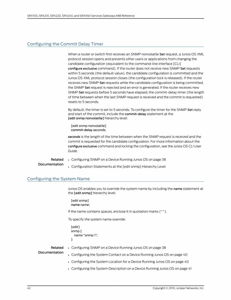
Configuring the Commit Delay Timer
When a router or switch first receives an SNMP nonvolatile Set request, a Junos OS XML
protocol session opens and prevents other users or applications from changing the
candidate configuration (equivalent to the command-line interface [CLI]
configure exclusive command). If the router does not receive new SNMP Set requests
within 5 seconds (the default value), the candidate configuration is committed and the
Junos OS XML protocol session closes (the configuration lock is released). If the router
receives new SNMP Set requests while the candidate configuration is being committed,
the SNMP Set request is rejected and an error is generated. If the router receives new
SNMP Set requests before 5 seconds have elapsed, the commit-delay timer (the length
of time between when the last SNMP request is received and the commit is requested)
resets to 5 seconds.
By default, the timer is set to 5 seconds. To configure the timer for the SNMP Set replyand start of the commit, include the commit-delay statement at the[edit snmp nonvolatile] hierarchy level:
[edit snmp nonvolatile]commit-delay seconds;
seconds is the length of the time between when the SNMP request is received and the
commit is requested for the candidate configuration. For more information about the
configure exclusive command and locking the configuration, see the Junos OS CLI User
Guide.
RelatedDocumentation
Configuring SNMP on a Device Running Junos OS on page 38•
• Configuration Statements at the [edit snmp] Hierarchy Level
Configuring the SystemName
Junos OS enables you to override the system name by including the name statement atthe [edit snmp] hierarchy level:
[edit snmp]name name;
If the name contains spaces, enclose it in quotation marks (" ").
To specify the system name override:
[edit]snmp {name "snmp 1";
}
RelatedDocumentation
Configuring SNMP on a Device Running Junos OS on page 38•
• Configuring the System Contact on a Device Running Junos OS on page 40
• Configuring the System Location for a Device Running Junos OS on page 40
• Configuring the System Description on a Device Running Junos OS on page 41
Copyright © 2010, Juniper Networks, Inc.42
SRX100, SRX210, SRX220, SRX240, and SRX650 Services Gateways MIB Reference
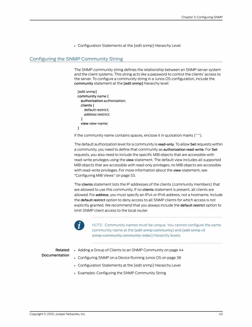
• Configuration Statements at the [edit snmp] Hierarchy Level
Configuring the SNMPCommunity String
The SNMP community string defines the relationship between an SNMP server systemand the client systems. This string acts like a password to control the clients’ access tothe server. To configure a community string in a Junos OS configuration, include thecommunity statement at the [edit snmp] hierarchy level:
[edit snmp]community name {authorization authorization;clients {default restrict;address restrict;
}view view-name;
}
If the community name contains spaces, enclose it in quotation marks (" ").
The default authorization level for a community is read-only. To allowSet requests within
a community, you need to define that community as authorization read-write. For Set
requests, you also need to include the specific MIB objects that are accessible with
read-write privileges using the view statement. The default view includes all supported
MIB objects that are accessible with read-only privileges; no MIB objects are accessible
with read-write privileges. For more information about the view statement, see
“Configuring MIB Views” on page 53.
The clients statement lists the IP addresses of the clients (community members) that
are allowed to use this community. If no clients statement is present, all clients are
allowed. For address, you must specify an IPv4 or IPv6 address, not a hostname. Include
the default restrict option to deny access to all SNMP clients for which access is not
explicitly granted. We recommend that you always include the default restrict option to
limit SNMP client access to the local router.
NOTE: Community namesmust be unique. You cannot configure the samecommunity name at the [edit snmp community] and [edit snmp v3
snmp-community community-index] hierarchy levels.
RelatedDocumentation
Adding a Group of Clients to an SNMP Community on page 44•
• Configuring SNMP on a Device Running Junos OS on page 38
• Configuration Statements at the [edit snmp] Hierarchy Level
• Examples: Configuring the SNMP Community String
43Copyright © 2010, Juniper Networks, Inc.
Chapter 3: Configuring SNMP

Adding a Group of Clients to an SNMPCommunity
Junos OS enables you to add one or more groups of clients to an SNMP community. You
can include the client-list-name name statement at the [edit snmp community
community-name] hierarchy level to add all the members of the client list or prefix list to
an SNMP community.
To define a list of clients, include the client-list statement followed by the IP addressesof the clients at the [edit snmp] hierarchy level:
[edit snmp]client-list client-list-name {ip-addresses;
}
You can configure a prefix list at the [edit policy options] hierarchy level. Support for
prefix lists in the SNMP community configuration enables you to use a single list to
configure the SNMP and routing policies. For more information about the prefix-list
statement, see the Junos OS Policy Framework Configuration Guide.
To add a client list or prefix list to an SNMP community, include the client-list-namestatement at the [edit snmp community community-name] hierarchy level:
[edit snmp community community-name]client-list-name client-list-name;
NOTE: The client list and prefix list must not have the same name.
The following example shows how to define a client list:
[edit]snmp {client-list clentlist1 {10.1.1.1/32;10.2.2.2/32;
}}
The following example shows how to add a client list to an SNMP community:
[edit]snmp {community community1 {authorization read-only;client-list-name clientlist1;
}}
The following example shows how to add a prefix list to an SNMP community:
[edit]policy-options {prefix-list prefixlist {10.3.3.3/32;
Copyright © 2010, Juniper Networks, Inc.44
SRX100, SRX210, SRX220, SRX240, and SRX650 Services Gateways MIB Reference
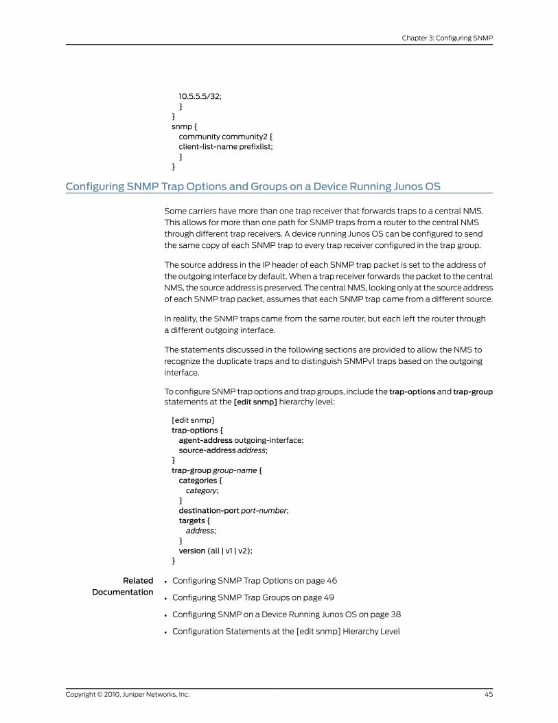
10.5.5.5/32;}
}snmp {community community2 {client-list-name prefixlist;}
}
Configuring SNMP Trap Options and Groups on a Device Running Junos OS
Some carriers have more than one trap receiver that forwards traps to a central NMS.
This allows for more than one path for SNMP traps from a router to the central NMS
through different trap receivers. A device running Junos OS can be configured to send
the same copy of each SNMP trap to every trap receiver configured in the trap group.
The source address in the IP header of each SNMP trap packet is set to the address of
the outgoing interface by default. When a trap receiver forwards the packet to the central
NMS, the source address is preserved. The central NMS, looking only at the source address
of each SNMP trap packet, assumes that each SNMP trap came from a different source.
In reality, the SNMP traps came from the same router, but each left the router through
a different outgoing interface.
The statements discussed in the following sections are provided to allow the NMS to
recognize the duplicate traps and to distinguish SNMPv1 traps based on the outgoing
interface.
To configure SNMP trap options and trap groups, include the trap-optionsand trap-groupstatements at the [edit snmp] hierarchy level:
[edit snmp]trap-options {agent-address outgoing-interface;source-address address;
}trap-group group-name {categories {category;
}destination-port port-number;targets {address;
}version (all | v1 | v2);
}
RelatedDocumentation
Configuring SNMP Trap Options on page 46•
• Configuring SNMP Trap Groups on page 49
• Configuring SNMP on a Device Running Junos OS on page 38
• Configuration Statements at the [edit snmp] Hierarchy Level
45Copyright © 2010, Juniper Networks, Inc.
Chapter 3: Configuring SNMP
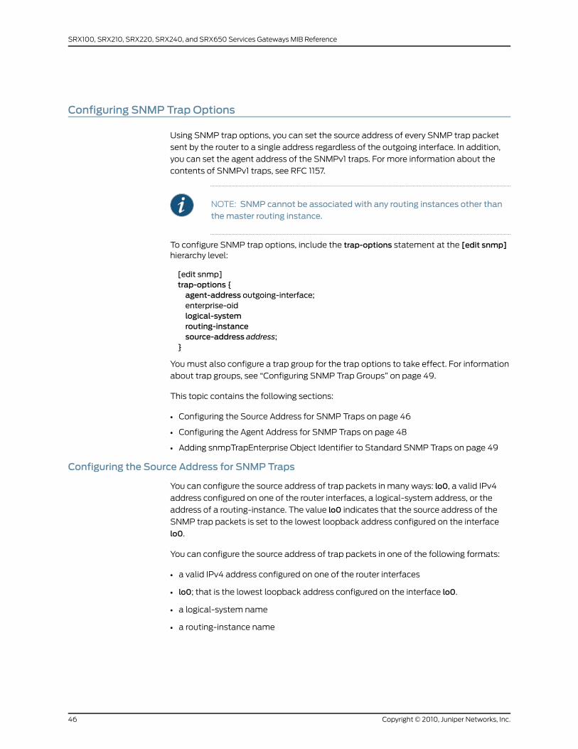
Configuring SNMP Trap Options
Using SNMP trap options, you can set the source address of every SNMP trap packet
sent by the router to a single address regardless of the outgoing interface. In addition,
you can set the agent address of the SNMPv1 traps. For more information about the
contents of SNMPv1 traps, see RFC 1157.
NOTE: SNMP cannot be associated with any routing instances other thanthemaster routing instance.
To configure SNMP trap options, include the trap-options statement at the [edit snmp]hierarchy level:
[edit snmp]trap-options {agent-address outgoing-interface;enterprise-oidlogical-systemrouting-instancesource-address address;
}
You must also configure a trap group for the trap options to take effect. For information
about trap groups, see “Configuring SNMP Trap Groups” on page 49.
This topic contains the following sections:
• Configuring the Source Address for SNMP Traps on page 46
• Configuring the Agent Address for SNMP Traps on page 48
• Adding snmpTrapEnterprise Object Identifier to Standard SNMP Traps on page 49
Configuring the Source Address for SNMP Traps
You can configure the source address of trap packets in many ways: lo0, a valid IPv4
address configured on one of the router interfaces, a logical-system address, or the
address of a routing-instance. The value lo0 indicates that the source address of the
SNMP trap packets is set to the lowest loopback address configured on the interface
lo0.
You can configure the source address of trap packets in one of the following formats:
• a valid IPv4 address configured on one of the router interfaces
• lo0; that is the lowest loopback address configured on the interface lo0.
• a logical-system name
• a routing-instance name
Copyright © 2010, Juniper Networks, Inc.46
SRX100, SRX210, SRX220, SRX240, and SRX650 Services Gateways MIB Reference
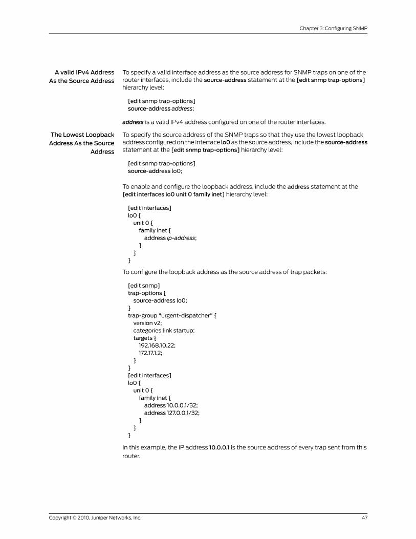
A valid IPv4 AddressAs the Source Address
To specify a valid interface address as the source address for SNMP traps on one of therouter interfaces, include the source-address statement at the [edit snmp trap-options]hierarchy level:
[edit snmp trap-options]source-address address;
address is a valid IPv4 address configured on one of the router interfaces.
The Lowest LoopbackAddress As the Source
Address
To specify the source address of the SNMP traps so that they use the lowest loopbackaddress configured on the interface lo0as the source address, include the source-addressstatement at the [edit snmp trap-options] hierarchy level:
[edit snmp trap-options]source-address lo0;
To enable and configure the loopback address, include the address statement at the[edit interfaces lo0 unit 0 family inet] hierarchy level:
[edit interfaces]lo0 {unit 0 {family inet {address ip-address;
}}
}
To configure the loopback address as the source address of trap packets:
[edit snmp]trap-options {source-address lo0;
}trap-group "urgent-dispatcher" {version v2;categories link startup;targets {192.168.10.22;172.17.1.2;
}}[edit interfaces]lo0 {unit 0 {family inet {address 10.0.0.1/32;address 127.0.0.1/32;
}}
}
In this example, the IP address 10.0.0.1 is the source address of every trap sent from this
router.
47Copyright © 2010, Juniper Networks, Inc.
Chapter 3: Configuring SNMP
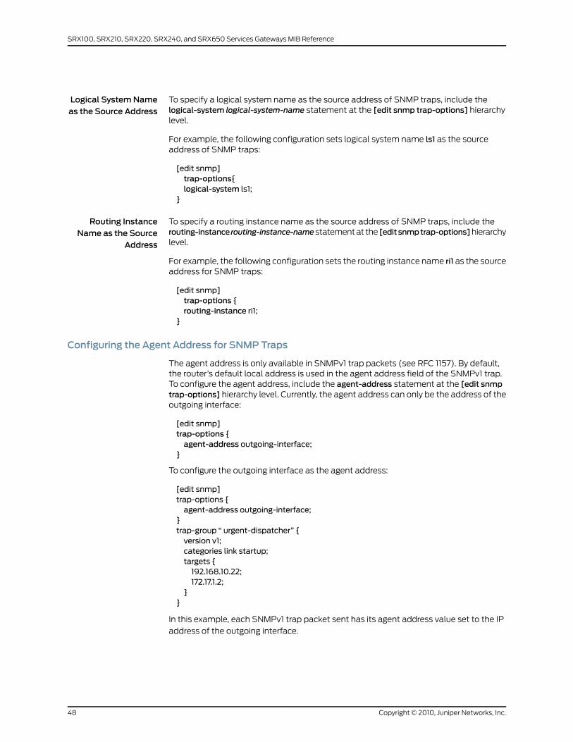
Logical SystemNameas the Source Address
To specify a logical system name as the source address of SNMP traps, include thelogical-system logical-system-name statement at the [edit snmp trap-options] hierarchylevel.
For example, the following configuration sets logical system name ls1 as the sourceaddress of SNMP traps:
[edit snmp]trap-options{logical-system ls1;
}
Routing InstanceName as the Source
Address
To specify a routing instance name as the source address of SNMP traps, include therouting-instance routing-instance-namestatement at the [editsnmptrap-options]hierarchylevel.
For example, the following configuration sets the routing instance name ri1 as the sourceaddress for SNMP traps:
[edit snmp]trap-options {routing-instance ri1;
}
Configuring the Agent Address for SNMP Traps
The agent address is only available in SNMPv1 trap packets (see RFC 1157). By default,the router’s default local address is used in the agent address field of the SNMPv1 trap.To configure the agent address, include the agent-address statement at the [edit snmptrap-options] hierarchy level. Currently, the agent address can only be the address of theoutgoing interface:
[edit snmp]trap-options {agent-address outgoing-interface;
}
To configure the outgoing interface as the agent address:
[edit snmp]trap-options {agent-address outgoing-interface;
}trap-group “ urgent-dispatcher” {version v1;categories link startup;targets {192.168.10.22;172.17.1.2;
}}
In this example, each SNMPv1 trap packet sent has its agent address value set to the IP
address of the outgoing interface.
Copyright © 2010, Juniper Networks, Inc.48
SRX100, SRX210, SRX220, SRX240, and SRX650 Services Gateways MIB Reference

Adding snmpTrapEnterprise Object Identifier to Standard SNMP Traps
The snmpTrapEnterprise object helps you identify the enterprise that has defined the
trap. Typically, the snmpTrapEnterprise object appears as the last varbind in
enterprise-specific SNMP version 2 traps. However, starting Release 10.0, Junos OS
enables you to add the snmpTrapEnterprise object identifier to standard SNMP traps as
well.
To add snmpTrapEnterprise to standard traps, include the enterprise-oid statement at
the [edit snmptrap-options]hierarchy level. If theenterprise-oid statement is not included
in the configuration, snmpTrapEnterprise is added only for enterprise-specific traps.
[edit snmp]trap-options {enterprise-oid;
}
RelatedDocumentation
Configuring SNMP Trap Options and Groups on a Device Running Junos OS on page 45•
• Configuring SNMP Trap Groups on page 49
• Configuring SNMP on a Device Running Junos OS on page 38
• Configuration Statements at the [edit snmp] Hierarchy Level
Configuring SNMP Trap Groups
You can create and name a group of one or more types of SNMP traps and then definewhich systems receive the group of SNMP traps. The trap group must be configured forSNMP traps to be sent. To create an SNMP trap group, include the trap-group statementat the [edit snmp] hierarchy level:
[edit snmp]trap-group group-name {categories {category;
}destination-port port-number;routing-instance instance;targets {address;
}version (all | v1 | v2);
}
The trap group name can be any string and is embedded in the community name field
of the trap. To configure your own trap group port, include thedestination-port statement.
The default destination port is port 162.
For each trap group that you define, you must include the target statement to define at
least one system as the recipient of the SNMP traps in the trap group. Specify the IPv4
or IPv6 address of each recipient, not its hostname.
49Copyright © 2010, Juniper Networks, Inc.
Chapter 3: Configuring SNMP
Specify the types of traps the trap group can receive in the categories statement. For
information about the category to which the traps belong, see the “Standard SNMP Traps
Supported on Devices Running Junos OS” and “Juniper Networks Enterprise-Specific
SNMP Traps” topics in the Junos OS SNMPMIBs and Traps Reference.
Specify the routing instance used by the trap group in the routing-instance statement.
All targets configured in the trap group use this routing instance.
A trap group can receive the following categories:
• authentication—Authentication failures
• chassis—Chassis or environment notifications
• configuration—Configuration notifications
• link—Link-related notifications (up-down transitions, DS-3 and DS-1 line status change,
IPv6 interface state change, and Passive Monitoring PIC overload)
NOTE: To send PassiveMonitoring PIC overload interface traps, select thelink trap category.
• remote-operations—Remote operation notifications
• rmon-alarm—Alarm for RMON events
• routing—Routing protocol notifications
• sonet-alarms—SONET/SDH alarms
NOTE: If you omit the SONET/SDH subcategories, all SONET/SDH trapalarm types are included in trap notifications.
• loss-of-light—Loss of light alarm notification
• pll-lock—PLL lock alarm notification
• loss-of-frame—Loss of frame alarm notification
• loss-of-signal—Loss of signal alarm notification
• severely-errored-frame—Severely errored frame alarm notification
• line-ais—Line alarm indication signal (AIS) alarm notification
• path-ais—Path AIS alarm notification
• loss-of-pointer—Loss of pointer alarm notification
• ber-defect—SONET/SDH bit error rate alarm defect notification
• ber-fault—SONET/SDH error rate alarm fault notification
Copyright © 2010, Juniper Networks, Inc.50
SRX100, SRX210, SRX220, SRX240, and SRX650 Services Gateways MIB Reference
• line-remote-defect-indication—Line remote defect indication alarm notification
• path-remote-defect-indication—Path remote defect indication alarm notification
• remote-error-indication—Remote error indication alarm notification
• unequipped—Unequipped alarm notification
• path-mismatch—Path mismatch alarm notification
• loss-of-cell—Loss of cell delineation alarm notification
• vt-ais—Virtual tributary (VT) AIS alarm notification
• vt-loss-of-pointer—VT loss of pointer alarm notification
• vt-remote-defect-indication—VT remote defect indication alarm notification
• vt-unequipped—VT unequipped alarm notification
• vt-label-mismatch—VT label mismatch error notification
• vt-loss-of-cell—VT loss of cell delineation notification
• startup—System warm and cold starts
• vrrp-events—Virtual Router Redundancy Protocol (VRRP) events such as new-master
or authentication failures
If you include SONET/SDH subcategories, only those SONET/SDH trap alarm types are
included in trap notifications.
The version statement allows you to specify the SNMP version of the traps sent to targets
of the trap group. If you specify v1 only, SNMPv1 traps are sent. If you specify v2 only,
SNMPv2 traps are sent. If you specify all, both an SNMPv1 and an SNMPv2 trap are sent
for every trap condition. For more information about the version statement, see version.
RelatedDocumentation
Configuring SNMP Trap Options and Groups on a Device Running Junos OS on page 45•
• Configuring SNMP Trap Options on page 46
• Configuring SNMP on a Device Running Junos OS on page 38
• Configuration Statements at the [edit snmp] Hierarchy Level
• Example: Configuring SNMP Trap Groups
Spoofing Enterprise-Specific SNMP Traps
You can use the request snmp spoof-trap operational mode command to mimic SNMP
trap behavior. The contents of the traps (the values and instances of the objects carried
in the trap) can be specified on the command line or they can be spoofed automatically.
This feature is useful if you want to trigger SNMP traps from routers and ensure they are
processed correctly within your existing network management infrastructure, but find it
51Copyright © 2010, Juniper Networks, Inc.
Chapter 3: Configuring SNMP
difficult to simulate the error conditions that trigger many of the traps on the router. For
more information, see the Junos OS System Basics and Services Command Reference.
RelatedDocumentation
Juniper Networks Enterprise-Specific SNMP Traps•
• Standard SNMP Traps Supported on Devices Running Junos OS
• Juniper Networks Enterprise-Specific MIBs on page 23
• Standard SNMP MIBs Supported by Junos OS on page 12
Configuring the Interfaces onWhich SNMPRequests Can Be Accepted
By default, all router interfaces have SNMP access privileges. To limit the access throughcertain interfaces only, include the interface statement at the [edit snmp] hierarchy level:
[edit snmp]interface [ interface-names ];
Specify the names of any logical or physical interfaces that should have SNMP access
privileges. Any SNMP requests entering the router from interfaces not listed are discarded.
RelatedDocumentation
Configuring SNMP on a Device Running Junos OS on page 38•
• Configuration Statements at the [edit snmp] Hierarchy Level
• Example: Configuring Secured Access List Checking
Filtering Interface Information Out of SNMPGet and GetNext Output
Junos OS enables you to filter out information related to specific interfaces from the
output of SNMP Get and GetNext requests performed on interface-related MIBs such as
IF MIB, ATM MIB, RMON MIB, and the Juniper Networks enterprise-specific IF MIB.
You can use the following options of the filter-interfaces statement at the [edit snmp]
hierarchy level to specify the interfaces that you want to exclude from SNMP Get and
GetNext queries:
• interfaces—Interfaces that match the specified regular expressions.
• all-internal-interfaces—Internal interfaces.
[edit]snmp {filter-interfaces {interfaces {interface1;interface2;
}all-internal-interfaces;
}}
Copyright © 2010, Juniper Networks, Inc.52
SRX100, SRX210, SRX220, SRX240, and SRX650 Services Gateways MIB Reference
However, note that these settings are limited to SNMP operations, and the users can
continue to access information related to the interfaces (including those hidden using
the filter-interfaces options) using the appropriate Junos OS command-line interface
(CLI) commands.
RelatedDocumentation
Configuring the Interfaces on Which SNMP Requests Can Be Accepted on page 52•
• Configuring SNMP on a Device Running Junos OS on page 38
• Configuration Statements at the [edit snmp] Hierarchy Level
ConfiguringMIB Views
By default, an SNMP community grants read access and denies write access to all
supported MIB objects (even communities configured as authorization read-write). To
restrict or grant read or write access to a set of MIB objects, you must configure a MIB
view and associate the view with a community.
To configure MIB views, include the view statement at the [edit snmp] hierarchy level:
[edit snmp]view view-name {oid object-identifier (include | exclude);
}
The view statement defines a MIB view and identifies a group of MIB objects to which
access is granted or denied; the include option grants access to the specified objects,
whereas the exclude option denies access to the specified objects. Each MIB object of a
view has a common object identifier (OID) prefix. Each object identifier represents a
subtree of the MIB object hierarchy. The subtree can be represented either by a sequence
of dotted integers (such as 1.3.6.1.2.1.2) or by its subtree name (such as interfaces). A
configuration statement uses a view to specify a group of MIB objects on which to define
access. You can also use wildcard character asterisk (*) to include OIDs that match a
particular pattern in the SNMP view. To enable a view, you must associate the view with
a community.
NOTE: To remove an OID completely, use the delete view all oid oid-number
command but omit the include parameter.
To associate MIB views with a community, include the view statement at the [edit snmpcommunity community-name] hierarchy level:
[edit snmp community community-name]view view-name;
For more information about the Ping MIB, see RFC 2925 and the “PING MIB” on page 339
topic in the Junos SNMPMIBs and Traps Reference.
RelatedDocumentation
Configuring SNMP on a Device Running Junos OS on page 38•
• Configuration Statements at the [edit snmp] Hierarchy Level
53Copyright © 2010, Juniper Networks, Inc.
Chapter 3: Configuring SNMP

• Example: Ping Proxy MIB
Tracing SNMPActivity on a Device Running Junos OS
SNMP tracing operations track activity for SNMP agents and record the information in
log files. The logged error descriptions provide detailed information to help you solve
problems faster.
By default, Junos OS does not trace any SNMP activity. If you include the traceoptions
statement at the [edit snmp] hierarchy level, the default tracing behavior is the following:
• Important activities are logged in files located in the /var/log directory. Each log is
named after the SNMP agent that generates it. Currently, the following log files are
created in the /var/log directory when the traceoptions statement is used:
• chassisd
• craftd
• ilmid
• mib2d
• rmopd
• serviced
• snmpd
• When a trace file named filename reaches its maximum size, it is renamed filename.0,
then filename.1, and so on, until the maximum number of trace files is reached. Then
the oldest trace file is overwritten. (For more information about how log files are created,
see the Junos OS System Log Messages Reference.)
• Log files can be accessed only by the user who configures the tracing operation.
You cannot change the directory (/var/log) in which trace files are located. However,you can customize the other trace file settings by including the following statements atthe [edit snmp] hierarchy level:
[edit snmp]traceoptions {file <files number> <match regular-expression> <size size> <world-readable |no-world-readable>;
flag flag;no-remote-trace;
}
These statements are described in the following sections:
• Configuring the Number and Size of SNMP Log Files on page 55
• Configuring Access to the Log File on page 55
Copyright © 2010, Juniper Networks, Inc.54
SRX100, SRX210, SRX220, SRX240, and SRX650 Services Gateways MIB Reference

• Configuring a Regular Expression for Lines to Be Logged on page 55
• Configuring the Trace Operations on page 56
Configuring the Number and Size of SNMP Log Files
By default, when the trace file reaches 128 kilobytes (KB) in size, it is renamed filename.0,
then filename.1, and so on, until there are three trace files. Then the oldest trace file
(filename.2) is overwritten.
You can configure the limits on the number and size of trace files by including the followingstatements at the [edit snmp traceoptions] hierarchy level:
[edit snmp traceoptions]file files number size size;
For example, set the maximum file size to 2 MB, and the maximum number of files to 20.
When the file that receives the output of the tracing operation (filename) reaches 2 MB,
filename is renamed filename.0, and a new file called filename is created. When the new
filename reaches 2 MB, filename.0 is renamed filename.1 and filename is renamed
filename.0. This process repeats until there are 20 trace files. Then the oldest file
(filename.19) is overwritten by the newest file (filename.0).
The number of files can be from 2 through 1000 files. The file size of each file can be from
10 KB through 1 gigabyte (GB).
Configuring Access to the Log File
By default, log files can be accessed only by the user who configures the tracing operation.
To specify that any user can read all log files, include the file world-readable statementat the [edit snmp traceoptions] hierarchy level:
[edit snmp traceoptions]file world-readable;
To explicitly set the default behavior, include the file no-world-readable statement at the[edit snmp traceoptions] hierarchy level:
[edit snmp traceoptions]file no-world-readable;
Configuring a Regular Expression for Lines to Be Logged
By default, the trace operation output includes all lines relevant to the logged activities.
You can refine the output by including thematch statement at the [edit snmptraceoptionsfile filename] hierarchy level and specifying a regular expression (regex) to be matched:
[edit snmp traceoptions]file filenamematch regular-expression;
55Copyright © 2010, Juniper Networks, Inc.
Chapter 3: Configuring SNMP
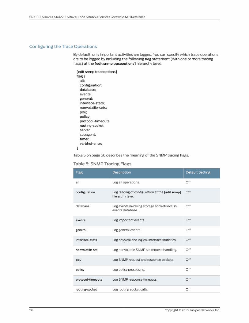
Configuring the Trace Operations
By default, only important activities are logged. You can specify which trace operationsare to be logged by including the following flag statement (with one or more tracingflags) at the [edit snmp traceoptions] hierarchy level:
[edit snmp traceoptions]flag {all;configuration;database;events;general;interface-stats;nonvolatile-sets;pdu;policy:protocol-timeouts;routing-socket;server;subagent;timer;varbind-error;
}
Table 5 on page 56 describes the meaning of the SNMP tracing flags.
Table 5: SNMP Tracing Flags
Default SettingDescriptionFlag
OffLog all operations.all
OffLog reading of configuration at the [edit snmp]hierarchy level.
configuration
OffLog events involving storage and retrieval inevents database.
database
OffLog important events.events
OffLog general events.general
OffLog physical and logical interface statistics.interface-stats
OffLog nonvolatile SNMP set request handling.nonvolatile-set
OffLog SNMP request and response packets.pdu
OffLog policy processing.policy
OffLog SNMP response timeouts.protocol-timeouts
OffLog routing socket calls.routing-socket
Copyright © 2010, Juniper Networks, Inc.56
SRX100, SRX210, SRX220, SRX240, and SRX650 Services Gateways MIB Reference
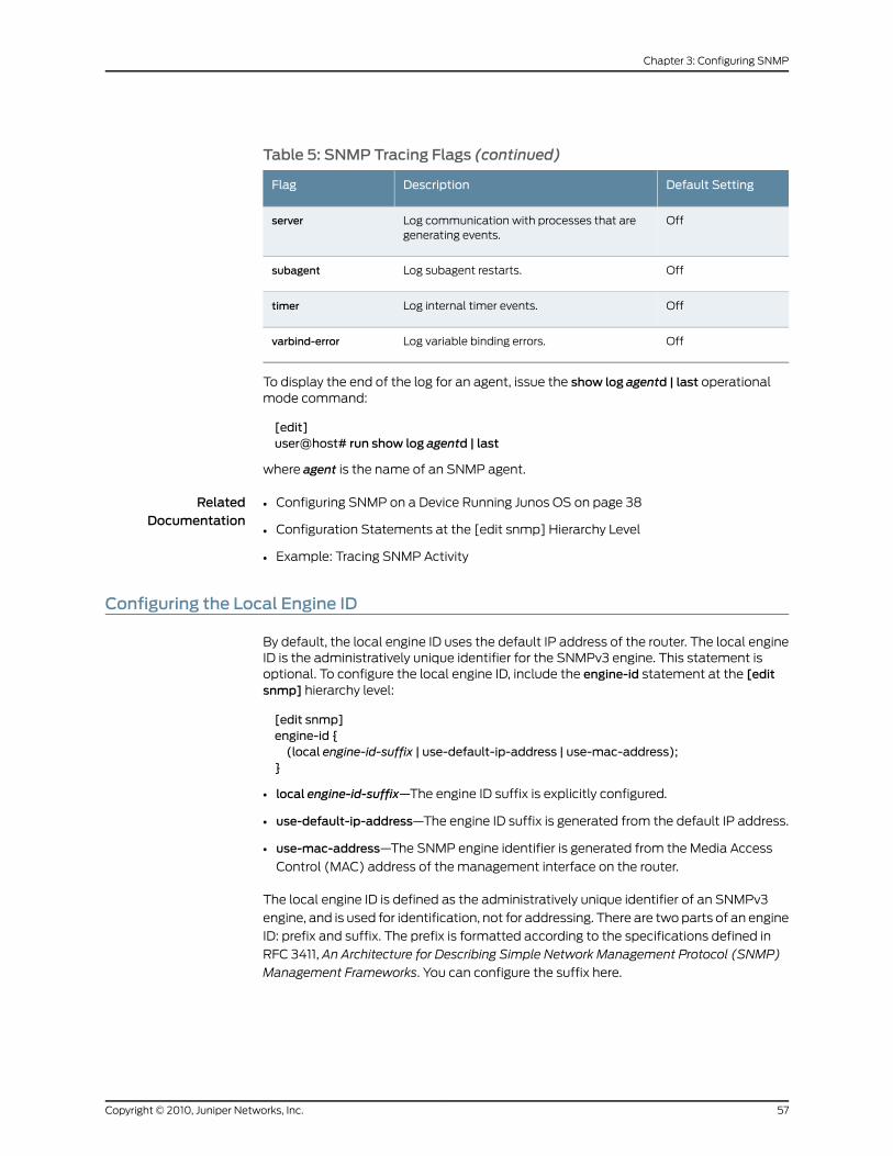
Table 5: SNMP Tracing Flags (continued)
Default SettingDescriptionFlag
OffLog communication with processes that aregenerating events.
server
OffLog subagent restarts.subagent
OffLog internal timer events.timer
OffLog variable binding errors.varbind-error
To display the end of the log for an agent, issue the show log agentd | last operationalmode command:
[edit]user@host# run show log agentd | last
where agent is the name of an SNMP agent.
RelatedDocumentation
Configuring SNMP on a Device Running Junos OS on page 38•
• Configuration Statements at the [edit snmp] Hierarchy Level
• Example: Tracing SNMP Activity
Configuring the Local Engine ID
By default, the local engine ID uses the default IP address of the router. The local engineID is the administratively unique identifier for the SNMPv3 engine. This statement isoptional. To configure the local engine ID, include the engine-id statement at the [editsnmp] hierarchy level:
[edit snmp]engine-id {(local engine-id-suffix | use-default-ip-address | use-mac-address);
}
• local engine-id-suffix—The engine ID suffix is explicitly configured.
• use-default-ip-address—The engine ID suffix is generated from the default IP address.
• use-mac-address—The SNMP engine identifier is generated from the Media Access
Control (MAC) address of the management interface on the router.
The local engine ID is defined as the administratively unique identifier of an SNMPv3
engine, and is used for identification, not for addressing. There are two parts of an engine
ID: prefix and suffix. The prefix is formatted according to the specifications defined in
RFC 3411, An Architecture for Describing Simple Network Management Protocol (SNMP)
Management Frameworks. You can configure the suffix here.
57Copyright © 2010, Juniper Networks, Inc.
Chapter 3: Configuring SNMP
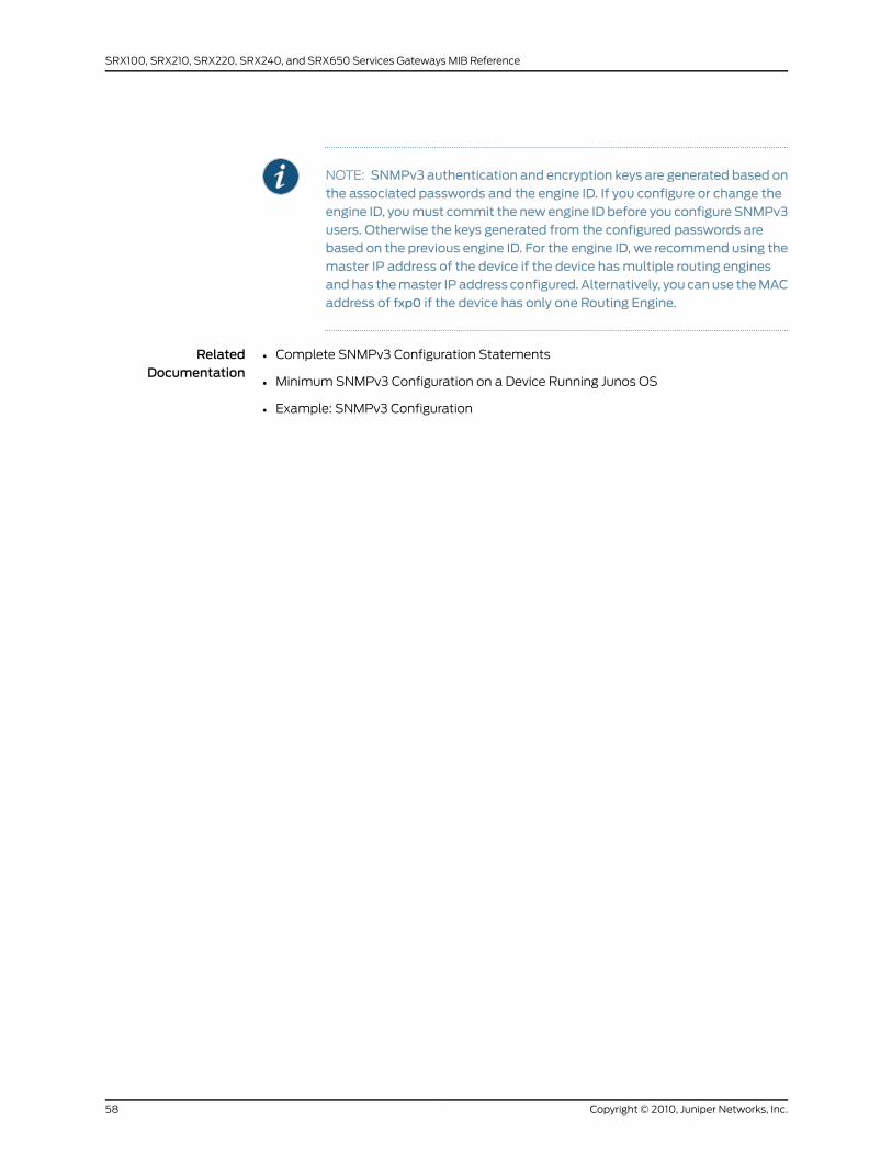
NOTE: SNMPv3 authentication and encryption keys are generated based onthe associated passwords and the engine ID. If you configure or change theengine ID, youmust commit the newengine ID before you configure SNMPv3users. Otherwise the keys generated from the configured passwords arebased on the previous engine ID. For the engine ID, we recommend using themaster IP address of the device if the device hasmultiple routing enginesandhas themaster IPaddress configured. Alternatively, you canuse theMACaddress of fxp0 if the device has only one Routing Engine.
RelatedDocumentation
• Complete SNMPv3 Configuration Statements
• Minimum SNMPv3 Configuration on a Device Running Junos OS
• Example: SNMPv3 Configuration
Copyright © 2010, Juniper Networks, Inc.58
SRX100, SRX210, SRX220, SRX240, and SRX650 Services Gateways MIB Reference
CHAPTER 4
Standard SNMP Traps
This chapter contains the following topics:
• Standard SNMP Traps Supported on Devices Running Junos OS on page 59
• Standard SNMP Version 1 Traps on page 59
• Standard SNMP Version 2 Traps on page 63
• Unsupported Standard SNMP Traps on page 67
Standard SNMP Traps Supported on Devices Running Junos OS
This topic gives you pointers to the standard SNMP traps supported by Junos OS.
NOTE: For scalability reasons, the MPLS traps are generated by the ingressrouter only. For information about disabling the generation of MPLS traps,see the Junos MPLS Applications Configuration Guide.
• Standard SNMP Version 1 Traps on page 59
• Standard SNMP Version 2 Traps on page 63
• Unsupported Standard SNMP Traps on page 67
RelatedDocumentation
Juniper Networks Enterprise-Specific SNMP Traps•
• Juniper Networks Enterprise-Specific MIBs on page 23
• Standard SNMP MIBs Supported by Junos OS on page 12
Standard SNMPVersion 1 Traps
Table 6 on page 60 provides an overview of the standard traps for SNMPv1. The traps
are organized first by trap category and then by trap name, and include their enterprise
ID, generic trap number, and specific trap number. The system logging severity levels are
listed for those traps that have them with their corresponding system log tag. Traps that
do not have corresponding system logging severity levels are marked with an en dash
(–) in the table.
59Copyright © 2010, Juniper Networks, Inc.

For more information about system log messages, see the JunosOSSystemLogMessages
Reference. For more information about configuring system logging, see the Junos OS
System Basics Configuration Guide.
Table 6: Standard Supported SNMPVersion 1 Traps
Supported onSyslog Tag
SystemLoggingSeverityLevel
SpecificTrapNumber
GenericTrapNumberEnterprise IDTrap NameDefined in
Startup Notifications
All devices runningJunos OS.
SNMPD_ TRAP_GEN_FAILURE
Notice041.3.6.1.4.1.2636authenticationFailureRFC 1215,Conventionsfor Defining
All devices runningJunos OS.
SNMPD_TRAP_COLD_START
Critical001.3.6.1.4.1.2636coldStartTraps forUse withthe SNMP
All devices runningJunos OS.
SNMPD_TRAP_WARM_START
Error011.3.6.1.4.1.2636warmStart
Link Notifications
All devices runningJunos OS.
SNMP_ TRAP_LINK_DOWN
Warning021.3.6.1.4.1.2636linkDownRFC 1215,Conventionsfor Defining
All devices runningJunos OS.
SNMP_TRAP_LINK_UP
Info031.3.6.1.4.1.2636linkUpTraps forUse withthe SNMP
Remote Operations Notifications
All devices runningJunos OS.
SNMP_TRAP _PING_PROBE_ FAILED
Info161.3.6.1.2.1.80.0pingProbeFailedRFC 2925,Definitionsof Managed
All devices runningJunos OS.
SNMP_TRAP_PING_TEST _FAILED
Info261.3.6.1.2.1.80.0pingTestFailedObjects forRemotePing,Traceroute,
All devices runningJunos OS.
SNMP_TRAP_PING_TEST_COMPLETED
Info361.3.6.1.2.1.80.0pingTestCompletedand LookupOperations
All devices runningJunos OS.
SNMP_TRAP_TRACE_ROUTE_PATH_CHANGE
Info161.3.6.1.2.1.81.0traceRoutePathChange
All devices runningJunos OS.
SNMP_TRAP_TRACE_ROUTE_TEST_FAILED
Info261.3.6.1.2.1.81.0traceRouteTestFailed
All devices runningJunos OS.
SNMP_TRAP_TRACE_ROUTE_TEST_COMPLETED
Info361.3.6.1.2.1.81.0traceRouteTestCompleted
Copyright © 2010, Juniper Networks, Inc.60
SRX100, SRX210, SRX220, SRX240, and SRX650 Services Gateways MIB Reference
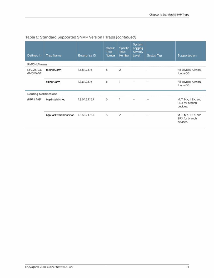
Table 6: Standard Supported SNMPVersion 1 Traps (continued)
Supported onSyslog Tag
SystemLoggingSeverityLevel
SpecificTrapNumber
GenericTrapNumberEnterprise IDTrap NameDefined in
RMONAlarms
All devices runningJunos OS.
––261.3.6.1.2.1.16fallingAlarmRFC 2819a,RMONMIB
All devices runningJunos OS.
––161.3.6.1.2.1.16risingAlarm
Routing Notifications
M, T, MX, J, EX, andSRX for branchdevices.
––161.3.6.1.2.1.15.7bgpEstablishedBGP 4MIB
M, T, MX, J, EX, andSRX for branchdevices.
––261.3.6.1.2.1.15.7bgpBackwardTransition
61Copyright © 2010, Juniper Networks, Inc.
Chapter 4: Standard SNMP Traps
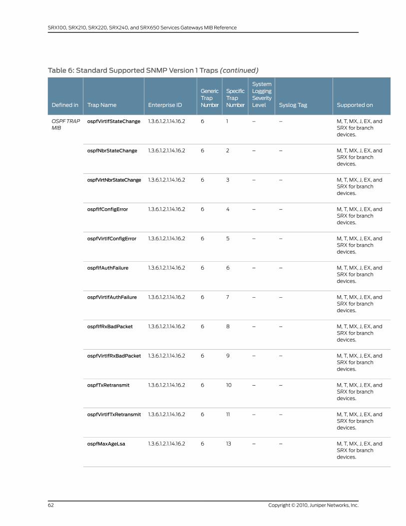
Table 6: Standard Supported SNMPVersion 1 Traps (continued)
Supported onSyslog Tag
SystemLoggingSeverityLevel
SpecificTrapNumber
GenericTrapNumberEnterprise IDTrap NameDefined in
M, T, MX, J, EX, andSRX for branchdevices.
––161.3.6.1.2.1.14.16.2ospfVirtIfStateChangeOSPFTRAPMIB
M, T, MX, J, EX, andSRX for branchdevices.
––261.3.6.1.2.1.14.16.2ospfNbrStateChange
M, T, MX, J, EX, andSRX for branchdevices.
––361.3.6.1.2.1.14.16.2ospfVirtNbrStateChange
M, T, MX, J, EX, andSRX for branchdevices.
––461.3.6.1.2.1.14.16.2ospfIfConfigError
M, T, MX, J, EX, andSRX for branchdevices.
––561.3.6.1.2.1.14.16.2ospfVirtIfConfigError
M, T, MX, J, EX, andSRX for branchdevices.
––661.3.6.1.2.1.14.16.2ospfIfAuthFailure
M, T, MX, J, EX, andSRX for branchdevices.
––761.3.6.1.2.1.14.16.2ospfVirtIfAuthFailure
M, T, MX, J, EX, andSRX for branchdevices.
––861.3.6.1.2.1.14.16.2ospfIfRxBadPacket
M, T, MX, J, EX, andSRX for branchdevices.
––961.3.6.1.2.1.14.16.2ospfVirtIfRxBadPacket
M, T, MX, J, EX, andSRX for branchdevices.
––1061.3.6.1.2.1.14.16.2ospfTxRetransmit
M, T, MX, J, EX, andSRX for branchdevices.
––1161.3.6.1.2.1.14.16.2ospfVirtIfTxRetransmit
M, T, MX, J, EX, andSRX for branchdevices.
––1361.3.6.1.2.1.14.16.2ospfMaxAgeLsa
Copyright © 2010, Juniper Networks, Inc.62
SRX100, SRX210, SRX220, SRX240, and SRX650 Services Gateways MIB Reference
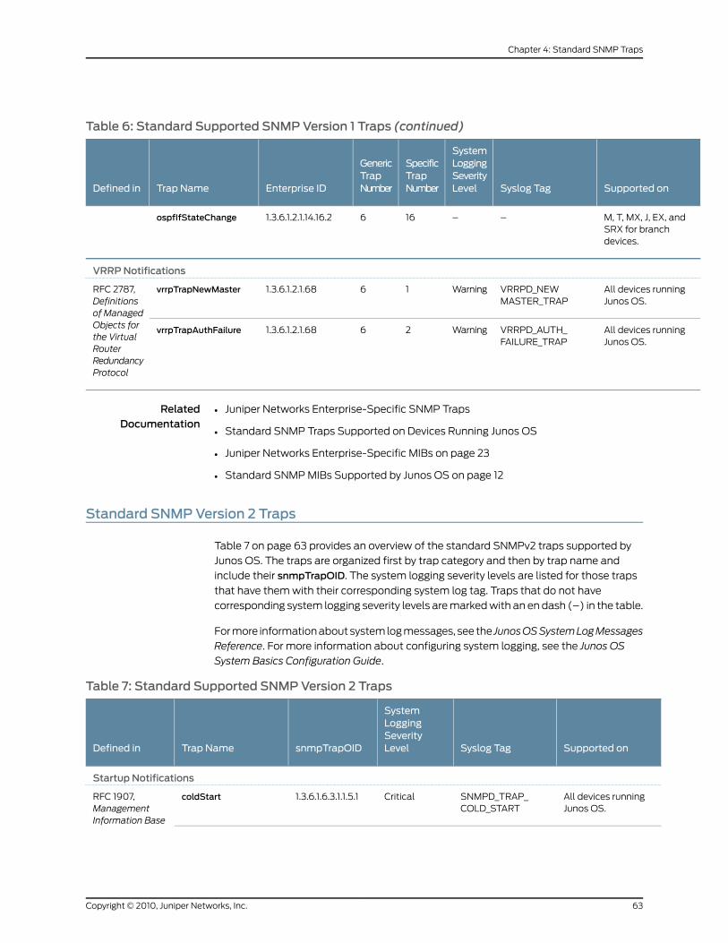
Table 6: Standard Supported SNMPVersion 1 Traps (continued)
Supported onSyslog Tag
SystemLoggingSeverityLevel
SpecificTrapNumber
GenericTrapNumberEnterprise IDTrap NameDefined in
M, T, MX, J, EX, andSRX for branchdevices.
––1661.3.6.1.2.1.14.16.2ospfIfStateChange
VRRPNotifications
All devices runningJunos OS.
VRRPD_NEWMASTER_TRAP
Warning161.3.6.1.2.1.68vrrpTrapNewMasterRFC 2787,Definitionsof Managed
All devices runningJunos OS.
VRRPD_AUTH_FAILURE_TRAP
Warning261.3.6.1.2.1.68vrrpTrapAuthFailureObjects forthe VirtualRouterRedundancyProtocol
RelatedDocumentation
Juniper Networks Enterprise-Specific SNMP Traps•
• Standard SNMP Traps Supported on Devices Running Junos OS
• Juniper Networks Enterprise-Specific MIBs on page 23
• Standard SNMP MIBs Supported by Junos OS on page 12
Standard SNMPVersion 2 Traps
Table 7 on page 63 provides an overview of the standard SNMPv2 traps supported by
Junos OS. The traps are organized first by trap category and then by trap name and
include their snmpTrapOID. The system logging severity levels are listed for those traps
that have them with their corresponding system log tag. Traps that do not have
corresponding system logging severity levels are marked with an en dash (–) in the table.
For more information about system log messages, see the JunosOSSystemLogMessages
Reference. For more information about configuring system logging, see the Junos OS
System Basics Configuration Guide.
Table 7: Standard Supported SNMPVersion 2 Traps
Supported onSyslog Tag
SystemLoggingSeverityLevelsnmpTrapOIDTrap NameDefined in
Startup Notifications
All devices runningJunos OS.
SNMPD_TRAP_COLD_START
Critical1.3.6.1.6.3.1.1.5.1coldStartRFC 1907,ManagementInformation Base
63Copyright © 2010, Juniper Networks, Inc.
Chapter 4: Standard SNMP Traps
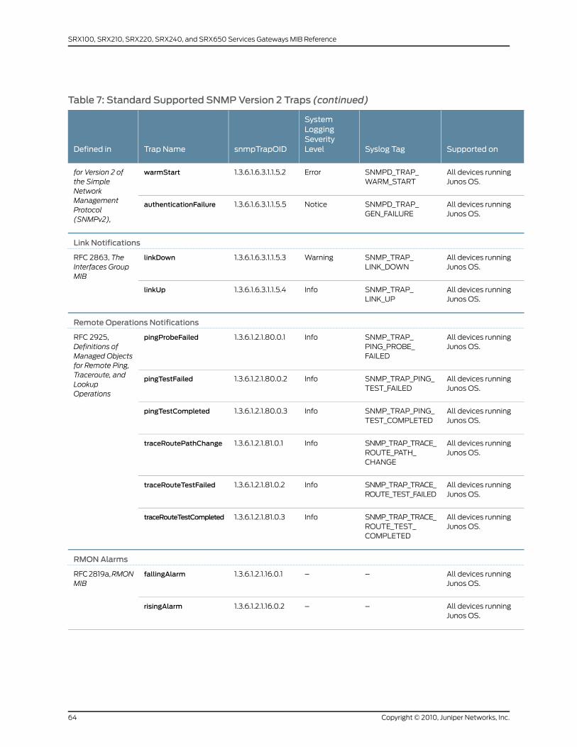
Table 7: Standard Supported SNMPVersion 2 Traps (continued)
Supported onSyslog Tag
SystemLoggingSeverityLevelsnmpTrapOIDTrap NameDefined in
All devices runningJunos OS.
SNMPD_TRAP_WARM_START
Error1.3.6.1.6.3.1.1.5.2warmStartfor Version 2 ofthe SimpleNetwork
All devices runningJunos OS.
SNMPD_TRAP_GEN_FAILURE
Notice1.3.6.1.6.3.1.1.5.5authenticationFailureManagementProtocol(SNMPv2),
Link Notifications
All devices runningJunos OS.
SNMP_TRAP_LINK_DOWN
Warning1.3.6.1.6.3.1.1.5.3linkDownRFC 2863, TheInterfaces GroupMIB
All devices runningJunos OS.
SNMP_TRAP_LINK_UP
Info1.3.6.1.6.3.1.1.5.4linkUp
Remote Operations Notifications
All devices runningJunos OS.
SNMP_TRAP_PING_PROBE_FAILED
Info1.3.6.1.2.1.80.0.1pingProbeFailedRFC 2925,Definitions ofManaged Objectsfor Remote Ping,
All devices runningJunos OS.
SNMP_TRAP_PING_TEST_FAILED
Info1.3.6.1.2.1.80.0.2pingTestFailedTraceroute, andLookupOperations
All devices runningJunos OS.
SNMP_TRAP_PING_TEST_COMPLETED
Info1.3.6.1.2.1.80.0.3pingTestCompleted
All devices runningJunos OS.
SNMP_TRAP_TRACE_ROUTE_PATH_CHANGE
Info1.3.6.1.2.1.81.0.1traceRoutePathChange
All devices runningJunos OS.
SNMP_TRAP_TRACE_ROUTE_TEST_FAILED
Info1.3.6.1.2.1.81.0.2traceRouteTestFailed
All devices runningJunos OS.
SNMP_TRAP_TRACE_ROUTE_TEST_COMPLETED
Info1.3.6.1.2.1.81.0.3traceRouteTestCompleted
RMONAlarms
All devices runningJunos OS.
––1.3.6.1.2.1.16.0.1fallingAlarmRFC 2819a,RMONMIB
All devices runningJunos OS.
––1.3.6.1.2.1.16.0.2risingAlarm
Copyright © 2010, Juniper Networks, Inc.64
SRX100, SRX210, SRX220, SRX240, and SRX650 Services Gateways MIB Reference
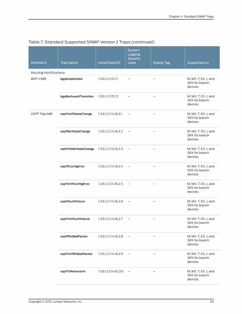
Table 7: Standard Supported SNMPVersion 2 Traps (continued)
Supported onSyslog Tag
SystemLoggingSeverityLevelsnmpTrapOIDTrap NameDefined in
Routing Notifications
M, MX, T, EX, J, andSRX for branchdevices.
––1.3.6.1.2.1.15.7.1bgpEstablishedBGP 4MIB
M, MX, T, EX, J, andSRX for branchdevices.
––1.3.6.1.2.1.15.7.2bgpBackwardTransition
M, MX, T, EX, J, andSRX for branchdevices.
––1.3.6.1.2.1.14.16.2.1ospfVirtIfStateChangeOSPF Trap MIB
M, MX, T, EX, J, andSRX for branchdevices.
––1.3.6.1.2.1.14.16.2.2ospfNbrStateChange
M, MX, T, EX, J, andSRX for branchdevices.
––1.3.6.1.2.1.14.16.2.3ospfVirtNbrStateChange
M, MX, T, EX, J, andSRX for branchdevices.
––1.3.6.1.2.1.14.16.2.4ospfIfConfigError
M, MX, T, EX, J, andSRX for branchdevices.
––1.3.6.1.2.1.14.16.2.5ospfVirtIfConfigError
M, MX, T, EX, J, andSRX for branchdevices.
––1.3.6.1.2.1.14.16.2.6ospfIfAuthFailure
M, MX, T, EX, J, andSRX for branchdevices.
––1.3.6.1.2.1.14.16.2.7ospfVirtIfAuthFailure
M, MX, T, EX, J, andSRX for branchdevices.
––1.3.6.1.2.1.14.16.2.8ospfIfRxBadPacket
M, MX, T, EX, J, andSRX for branchdevices.
––1.3.6.1.2.1.14.16.2.9ospfVirtIfRxBadPacket
M, MX, T, EX, J, andSRX for branchdevices.
––1.3.6.1.2.1.14.16.2.10ospfTxRetransmit
65Copyright © 2010, Juniper Networks, Inc.
Chapter 4: Standard SNMP Traps
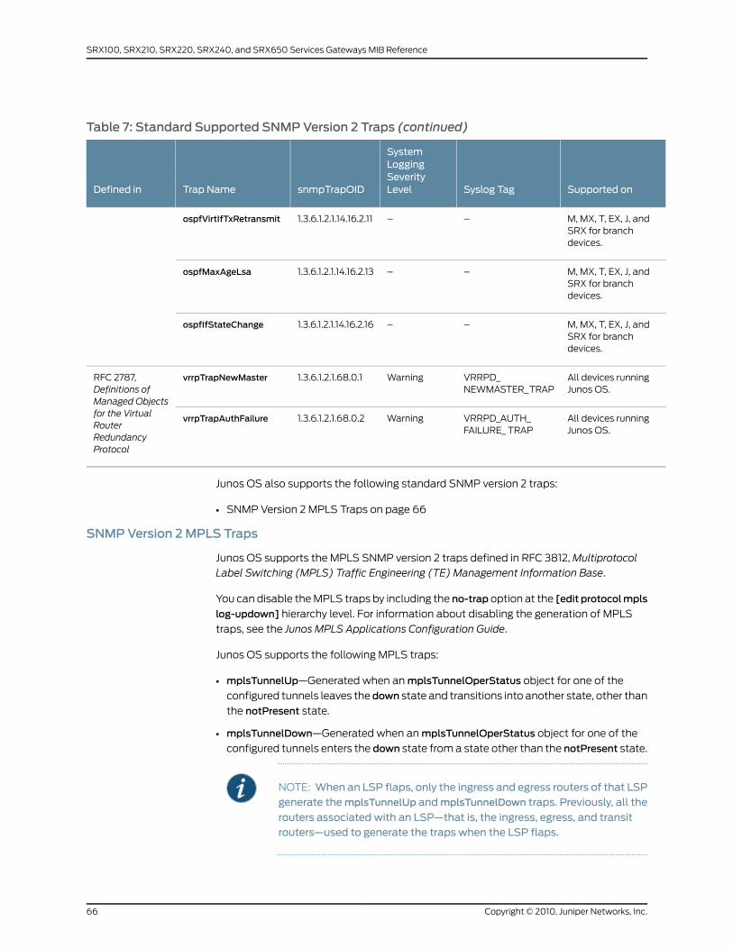
Table 7: Standard Supported SNMPVersion 2 Traps (continued)
Supported onSyslog Tag
SystemLoggingSeverityLevelsnmpTrapOIDTrap NameDefined in
M, MX, T, EX, J, andSRX for branchdevices.
––1.3.6.1.2.1.14.16.2.11ospfVirtIfTxRetransmit
M, MX, T, EX, J, andSRX for branchdevices.
––1.3.6.1.2.1.14.16.2.13ospfMaxAgeLsa
M, MX, T, EX, J, andSRX for branchdevices.
––1.3.6.1.2.1.14.16.2.16ospfIfStateChange
All devices runningJunos OS.
VRRPD_NEWMASTER_ TRAP
Warning1.3.6.1.2.1.68.0.1vrrpTrapNewMasterRFC 2787,Definitions ofManaged Objectsfor the VirtualRouterRedundancyProtocol
All devices runningJunos OS.
VRRPD_AUTH_FAILURE_ TRAP
Warning1.3.6.1.2.1.68.0.2vrrpTrapAuthFailure
Junos OS also supports the following standard SNMP version 2 traps:
• SNMP Version 2 MPLS Traps on page 66
SNMPVersion 2MPLS Traps
Junos OS supports the MPLS SNMP version 2 traps defined in RFC 3812, Multiprotocol
Label Switching (MPLS) Traffic Engineering (TE) Management Information Base.
You can disable the MPLS traps by including the no-trap option at the [edit protocolmpls
log-updown] hierarchy level. For information about disabling the generation of MPLS
traps, see the Junos MPLS Applications Configuration Guide.
Junos OS supports the following MPLS traps:
• mplsTunnelUp—Generated when an mplsTunnelOperStatus object for one of the
configured tunnels leaves thedown state and transitions into another state, other than
the notPresent state.
• mplsTunnelDown—Generated when an mplsTunnelOperStatus object for one of the
configured tunnels enters the down state from a state other than the notPresent state.
NOTE: When an LSP flaps, only the ingress and egress routers of that LSPgenerate themplsTunnelUp andmplsTunnelDown traps. Previously, all the
routers associated with an LSP—that is, the ingress, egress, and transitrouters—used to generate the traps when the LSP flaps.
Copyright © 2010, Juniper Networks, Inc.66
SRX100, SRX210, SRX220, SRX240, and SRX650 Services Gateways MIB Reference
• mplsTunnelRerouted—Generated when a tunnel is rerouted.
• mplsTunnelReoptimized—Generated when a tunnel is reoptimized.
NOTE: In Junos OS Release 8.3 and earlier,mplsTunnelReoptimizedwas
generated every time the optimization timer expired; that is, when theoptimization timerexceededthevalueset for theoptimize-timerstatement
at the [edit protocolsmpls label-switched-path path-name] hierarchy level.
However, in Release8.4 and later, this trap is generatedonlywhen thepathis reoptimized, and not when the optimization timer expires.
RelatedDocumentation
Juniper Networks Enterprise-Specific SNMP Traps•
• Standard SNMP Traps Supported on Devices Running Junos OS
• Juniper Networks Enterprise-Specific MIBs on page 23
• Standard SNMP MIBs Supported by Junos OS on page 12
Unsupported Standard SNMP Traps
Standard SNMP traps that are defined in Junos OS but are not generated are shown in
Table 8 on page 68.
67Copyright © 2010, Juniper Networks, Inc.
Chapter 4: Standard SNMP Traps
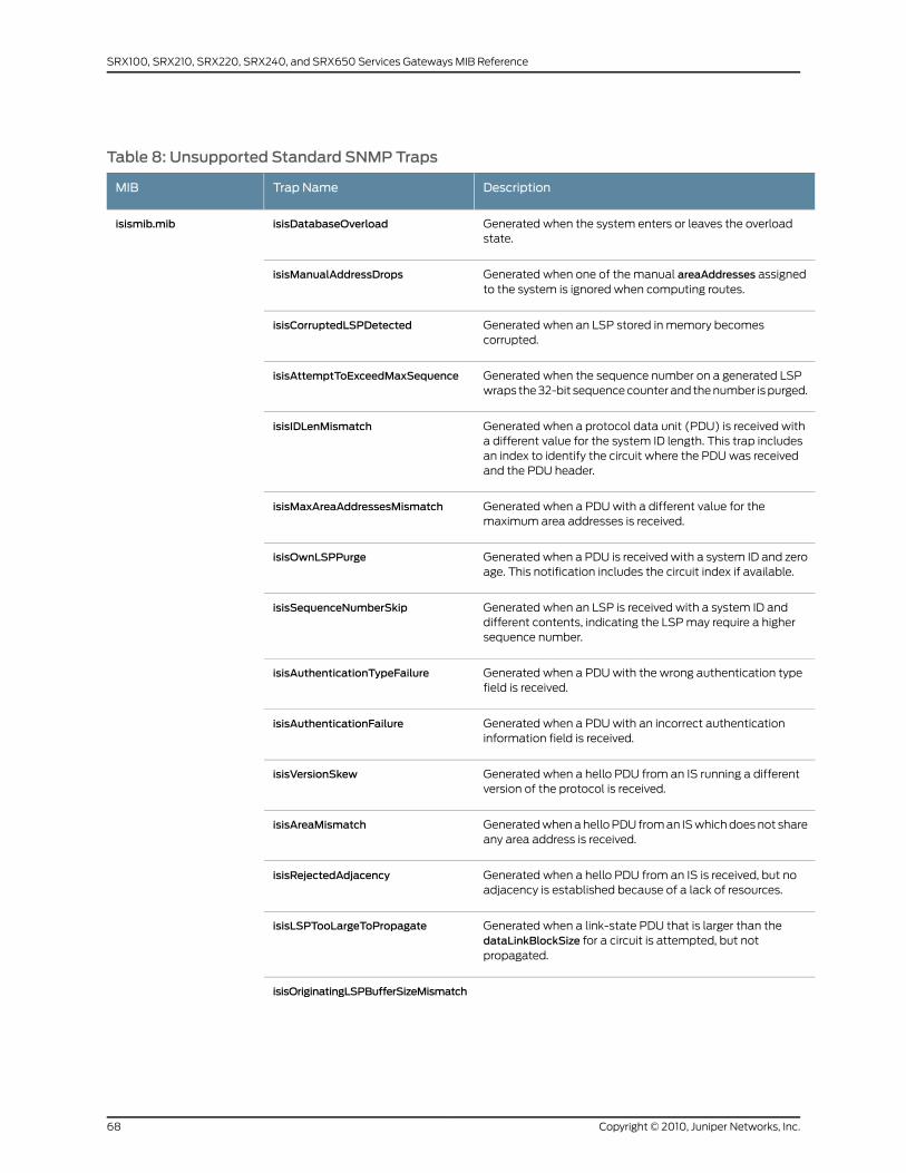
Table 8: Unsupported Standard SNMP Traps
DescriptionTrap NameMIB
Generated when the system enters or leaves the overloadstate.
isisDatabaseOverloadisismib.mib
Generated when one of the manual areaAddresses assignedto the system is ignored when computing routes.
isisManualAddressDrops
Generated when an LSP stored in memory becomescorrupted.
isisCorruptedLSPDetected
Generated when the sequence number on a generated LSPwraps the 32-bit sequence counter and the number is purged.
isisAttemptToExceedMaxSequence
Generated when a protocol data unit (PDU) is received witha different value for the system ID length. This trap includesan index to identify the circuit where the PDU was receivedand the PDU header.
isisIDLenMismatch
Generated when a PDU with a different value for themaximum area addresses is received.
isisMaxAreaAddressesMismatch
Generated when a PDU is received with a system ID and zeroage. This notification includes the circuit index if available.
isisOwnLSPPurge
Generated when an LSP is received with a system ID anddifferent contents, indicating the LSP may require a highersequence number.
isisSequenceNumberSkip
Generated when a PDU with the wrong authentication typefield is received.
isisAuthenticationTypeFailure
Generated when a PDU with an incorrect authenticationinformation field is received.
isisAuthenticationFailure
Generated when a hello PDU from an IS running a differentversion of the protocol is received.
isisVersionSkew
Generated when a hello PDU from an IS which does not shareany area address is received.
isisAreaMismatch
Generated when a hello PDU from an IS is received, but noadjacency is established because of a lack of resources.
isisRejectedAdjacency
Generated when a link-state PDU that is larger than thedataLinkBlockSize for a circuit is attempted, but notpropagated.
isisLSPTooLargeToPropagate
isisOriginatingLSPBufferSizeMismatch
Copyright © 2010, Juniper Networks, Inc.68
SRX100, SRX210, SRX220, SRX240, and SRX650 Services Gateways MIB Reference
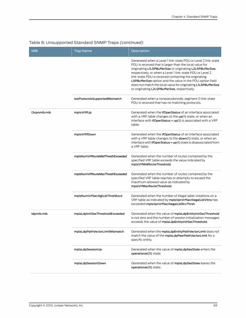
Table 8: Unsupported Standard SNMP Traps (continued)
DescriptionTrap NameMIB
Generated when a Level 1 link-state PDU or Level 2 link-statePDU is received that is larger than the local value fororiginating L1LSPBufferSize or originating L2LSPBufferSize,respectively, or when a Level 1 link-state PDU or Level 2link-state PDU is received containing the originatingLSPBufferSize option and the value in the PDU option fielddoes not match the local value for originatingL1LSPBufferSizeor originating L2LSPBufferSize, respectively.
Generated when a nonpseudonode, segment 0 link-statePDU is received that has no matching protocols.
isisProtocolsSupportedMismatch
Generated when the ifOperStatus of an interface associatedwith a VRF table changes to the up(1) state, or when aninterface with ifOperStatus = up(1) is associated with a VRFtable.
mplsVrfIfUpl3vpnmib.mib
Generated when the ifOperStatus of an interface associatedwith a VRF table changes to the down(1) state, or when aninterface with ifOperStatus=up(1) state is disassociated froma VRF table.
mplsVrfIfDown
Generated when the number of routes contained by thespecified VRF table exceeds the value indicated bymplsVrfMidRouteThreshold.
mplsNumVrfRouteMidThreshExceeded
Generated when the number of routes contained by thespecified VRF table reaches or attempts to exceed themaximum allowed value as indicated bymplsVrfMaxRouteThreshold.
mplsNumVrfRouteMaxThreshExceeded
Generated when the number of illegal label violations on aVRF table as indicated by mplsVpnVrfSecIllegalLblVltns hasexceeded mplsVpnVrfSecIllegalLblRcvThrsh.
mplsNumVrfSecIllglLblThrshExcd
Generated when the value of mplsLdpEntityInitSesThresholdis not zero and the number of session initialization messagesexceeds the value of mplsLdpEntityInitSesThreshold.
mplsLdpInitSesThresholdExceededldpmib.mib
Generated when themplsLdpEntityPathVectorLimit does notmatch the value of the mplsLdpPeerPathVectorLimit for aspecific entity.
mplsLdpPathVectorLimitMismatch
Generated when the value of mplsLdpSesState enters theoperational(5) state.
mplsLdpSessionUp
Generated when the value of mplsLdpSesState leaves theoperational(5) state.
mplsLdpSessionDown
69Copyright © 2010, Juniper Networks, Inc.
Chapter 4: Standard SNMP Traps

Table 8: Unsupported Standard SNMP Traps (continued)
DescriptionTrap NameMIB
Generated when the Multicast Source Discovery Protocol(MSDP) finite state machine (FSM) enters the Establishedstate.
msdpEstablishedmsdpmib.mib
Generated when the MSDP FSM moves from a highernumbered state to a lower numbered state.
msdpBackwardTransition
Generated when a new LSA is originated by the router becauseof a topology change.
ospfOriginateLsaospf2trap.mib
Generated when the number of LSAs in the router's link-statedatabase exceeds the value of ospfExtLsdbLimit.
ospfLsdbOverflow
Generated when the number of LSAs in the router's link-statedatabase exceeds 90 percent of the value ofospfExtLsdbLimit.
ospfLsdbApproachingOverflow
Generated when the state of an SDLC port transitions toactive or inactive.
sdlcPortStatusChangerfc1747.mib
Generated when the state of an SDLC link station transitionsto contacted or disconnected.
sdlcLSStatusChange
Generated when a virtual circuit changes state (has beencreated or invalidated, or has toggled between the active andinactive states).
frDLCIStatusChangerfc2115a.mib
Generated when the ATUCs transmit rate has changed(RADSL mode only).
adslAtucRateChangeTraprfc2662.mib
Generated when the loss of framing 15-minute intervalthreshold is reached.
adslAtucPerfLofsThreshTrap
Generated when ATUC initialization fails.adslAtucInitFailureTrap
Generated when the loss of power 15-minute intervalthreshold is reached.
adslAturPerfLprsThreshTrap
Generated when the ATURs transmit rate changes (RADSLmode only).
adslAturRateChangeTrap
Generated when a bundle link mismatch is detected.mfrMibTrapBundleLinkMismatchrfc3020.mib
Generated when mplsXCOperStatus for one or morecontiguous entries inmplsXCTableenters theup(1) state fromsome other state.
mplsXCUprfc3813.mib
Generated when mplsXCOperStatus for one or morecontiguous entries in mplsXCTable enters the down(2) statefrom some other state.
mplsXCDown
Copyright © 2010, Juniper Networks, Inc.70
SRX100, SRX210, SRX220, SRX240, and SRX650 Services Gateways MIB Reference

RelatedDocumentation
• Juniper Networks Enterprise-Specific SNMP Traps
• Standard SNMP Traps Supported on Devices Running Junos OS
• Juniper Networks Enterprise-Specific MIBs on page 23
• Standard SNMP MIBs Supported by Junos OS on page 12
71Copyright © 2010, Juniper Networks, Inc.
Chapter 4: Standard SNMP Traps

Copyright © 2010, Juniper Networks, Inc.72
SRX100, SRX210, SRX220, SRX240, and SRX650 Services Gateways MIB Reference
CHAPTER 5
Juniper Networks Enterprise-SpecificSNMP Traps
This chapter contains the following topics:
• Juniper Networks Enterprise-Specific SNMP Traps on page 73
• Juniper Networks Enterprise-Specific SNMP Version 1 Traps on page 74
• Juniper Networks Enterprise-Specific SNMP Version 2 Traps on page 81
• Juniper Networks Enterprise-Specific BGP Traps on page 87
• Juniper Networks Enterprise-Specific LDP Traps on page 88
• Juniper Networks Enterprise-Specific MIMSTP Traps on page 88
• Enterprise-Specific MPLS Traps on page 89
• Configuring SNMP Informs on page 90
• Configuring SNMPv3 Traps on a Device Running Junos OS on page 91
Juniper Networks Enterprise-Specific SNMP Traps
This topic gives you pointers to the enterprise-specific SNMP traps supported by Junos
OS.
NOTE: All enterprise-specific SNMP traps supported by Junos OS can besent in version 1, 2, and 3 formats.
• Juniper Networks Enterprise-Specific SNMP Version 1 Traps on page 74
• Juniper Networks Enterprise-Specific SNMP Version 2 Traps on page 81
• Juniper Networks Enterprise-Specific BGP Traps on page 87
• Juniper Networks Enterprise-Specific LDP Traps on page 88
• Juniper Networks Enterprise-Specific MIMSTP Traps on page 88
• Enterprise-Specific MPLS Traps on page 89
73Copyright © 2010, Juniper Networks, Inc.
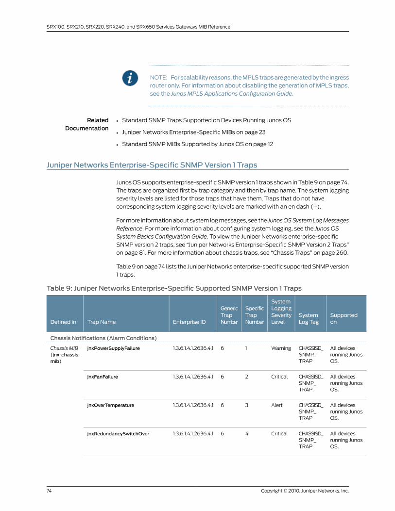
NOTE: Forscalability reasons, theMPLStrapsaregeneratedbythe ingressrouter only. For information about disabling the generation of MPLS traps,see the Junos MPLS Applications Configuration Guide.
RelatedDocumentation
Standard SNMP Traps Supported on Devices Running Junos OS•
• Juniper Networks Enterprise-Specific MIBs on page 23
• Standard SNMP MIBs Supported by Junos OS on page 12
Juniper Networks Enterprise-Specific SNMPVersion 1 Traps
Junos OS supports enterprise-specific SNMP version 1 traps shown in Table 9 on page 74.
The traps are organized first by trap category and then by trap name. The system logging
severity levels are listed for those traps that have them. Traps that do not have
corresponding system logging severity levels are marked with an en dash (–).
For more information about system log messages, see the JunosOSSystemLogMessages
Reference. For more information about configuring system logging, see the Junos OS
System Basics Configuration Guide. To view the Juniper Networks enterprise-specific
SNMP version 2 traps, see “Juniper Networks Enterprise-Specific SNMP Version 2 Traps”
on page 81. For more information about chassis traps, see “Chassis Traps” on page 260.
Table 9 on page 74 lists the Juniper Networks enterprise-specific supported SNMP version
1 traps.
Table 9: Juniper Networks Enterprise-Specific Supported SNMPVersion 1 Traps
Supportedon
SystemLog Tag
SystemLoggingSeverityLevel
SpecificTrapNumber
GenericTrapNumberEnterprise IDTrap NameDefined in
Chassis Notifications (Alarm Conditions)
All devicesrunning JunosOS.
CHASSISD_SNMP_TRAP
Warning161.3.6.1.4.1.2636.4.1jnxPowerSupplyFailureChassis MIB(jnx-chassis.mib)
All devicesrunning JunosOS.
CHASSISD_SNMP_TRAP
Critical261.3.6.1.4.1.2636.4.1jnxFanFailure
All devicesrunning JunosOS.
CHASSISD_SNMP_TRAP
Alert361.3.6.1.4.1.2636.4.1jnxOverTemperature
All devicesrunning JunosOS.
CHASSISD_SNMP_TRAP
Critical461.3.6.1.4.1.2636.4.1jnxRedundancySwitchOver
Copyright © 2010, Juniper Networks, Inc.74
SRX100, SRX210, SRX220, SRX240, and SRX650 Services Gateways MIB Reference
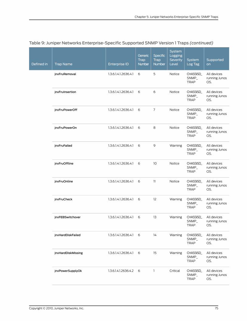
Table 9: Juniper Networks Enterprise-Specific Supported SNMPVersion 1 Traps (continued)
Supportedon
SystemLog Tag
SystemLoggingSeverityLevel
SpecificTrapNumber
GenericTrapNumberEnterprise IDTrap NameDefined in
All devicesrunning JunosOS.
CHASSISD_SNMP_TRAP
Notice561.3.6.1.4.1.2636.4.1jnxFruRemoval
All devicesrunning JunosOS.
CHASSISD_SNMP_TRAP
Notice661.3.6.1.4.1.2636.4.1jnxFruInsertion
All devicesrunning JunosOS.
CHASSISD_SNMP_TRAP
Notice761.3.6.1.4.1.2636.4.1jnxFruPowerOff
All devicesrunning JunosOS.
CHASSISD_SNMP_TRAP
Notice861.3.6.1.4.1.2636.4.1jnxFruPowerOn
All devicesrunning JunosOS.
CHASSISD_SNMP_TRAP
Warning961.3.6.1.4.1.2636.4.1jnxFruFailed
All devicesrunning JunosOS.
CHASSISD_SNMP_TRAP
Notice1061.3.6.1.4.1.2636.4.1jnxFruOffline
All devicesrunning JunosOS.
CHASSISD_SNMP_TRAP
Notice1161.3.6.1.4.1.2636.4.1jnxFruOnline
All devicesrunning JunosOS.
CHASSISD_SNMP_TRAP
Warning1261.3.6.1.4.1.2636.4.1jnxFruCheck
All devicesrunning JunosOS.
CHASSISD_SNMP_TRAP
Warning1361.3.6.1.4.1.2636.4.1jnxFEBSwitchover
All devicesrunning JunosOS.
CHASSISD_SNMP_TRAP
Warning1461.3.6.1.4.1.2636.4.1jnxHardDiskFailed
All devicesrunning JunosOS.
CHASSISD_SNMP_TRAP
Warning1561.3.6.1.4.1.2636.4.1jnxHardDiskMissing
All devicesrunning JunosOS.
CHASSISD_SNMP_TRAP
Critical161.3.6.1.4.1.2636.4.2jnxPowerSupplyOk
75Copyright © 2010, Juniper Networks, Inc.
Chapter 5: Juniper Networks Enterprise-Specific SNMP Traps
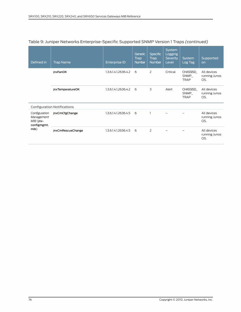
Table 9: Juniper Networks Enterprise-Specific Supported SNMPVersion 1 Traps (continued)
Supportedon
SystemLog Tag
SystemLoggingSeverityLevel
SpecificTrapNumber
GenericTrapNumberEnterprise IDTrap NameDefined in
All devicesrunning JunosOS.
CHASSISD_SNMP_TRAP
Critical261.3.6.1.4.1.2636.4.2jnxFanOK
All devicesrunning JunosOS.
CHASSISD_SNMP_TRAP
Alert361.3.6.1.4.1.2636.4.2jnxTemperatureOK
Configuration Notifications
All devicesrunning JunosOS.
––161.3.6.1.4.1.2636.4.5jnxCmCfgChangeConfigurationManagementMIB (jnx-configmgmt.mib) All devices
running JunosOS.
––261.3.6.1.4.1.2636.4.5jnxCmRescueChange
Copyright © 2010, Juniper Networks, Inc.76
SRX100, SRX210, SRX220, SRX240, and SRX650 Services Gateways MIB Reference

Table 9: Juniper Networks Enterprise-Specific Supported SNMPVersion 1 Traps (continued)
Supportedon
SystemLog Tag
SystemLoggingSeverityLevel
SpecificTrapNumber
GenericTrapNumberEnterprise IDTrap NameDefined in
Link Notifications
Devices thatrun Junos OSand havecollector PICsinstalled.
––161.3.6.1.4.1.2636.4.8jnxCollUnavailableDestFlowCollectionServices MIB(jnx-coll.mib)
Devices thatrun Junos OSand havecollector PICsinstalled.
––261.3.6.1.4.1.2636.4.8jnxCollUnavailableDestCleared
Devices thatrun Junos OSand havecollector PICsinstalled.
––361.3.6.1.4.1.2636.4.8jnxCollUnsuccessfulTransfer
Devices thatrun Junos OSand havecollector PICsinstalled.
––461.3.6.1.4.1.2636.4.8jnxCollFlowOverload
Devices thatrun Junos OSand havecollector PICsinstalled.
––561.3.6.1.4.1.2636.4.8jnxCollFlowOverloadCleared
Devices thatrun Junos OSand havecollector PICsinstalled.
––661.3.6.1.4.1.2636.4.8jnxCollMemoryUnavailable
Devices thatrun Junos OSand havecollector PICsinstalled.
––761.3.6.1.4.1.2636.4.8jnxCollMemoryAvailable
Devices thatrun Junos OSand havecollector PICsinstalled.
––861.3.6.1.4.1.2636.4.8jnxCollFtpSwitchover
77Copyright © 2010, Juniper Networks, Inc.
Chapter 5: Juniper Networks Enterprise-Specific SNMP Traps
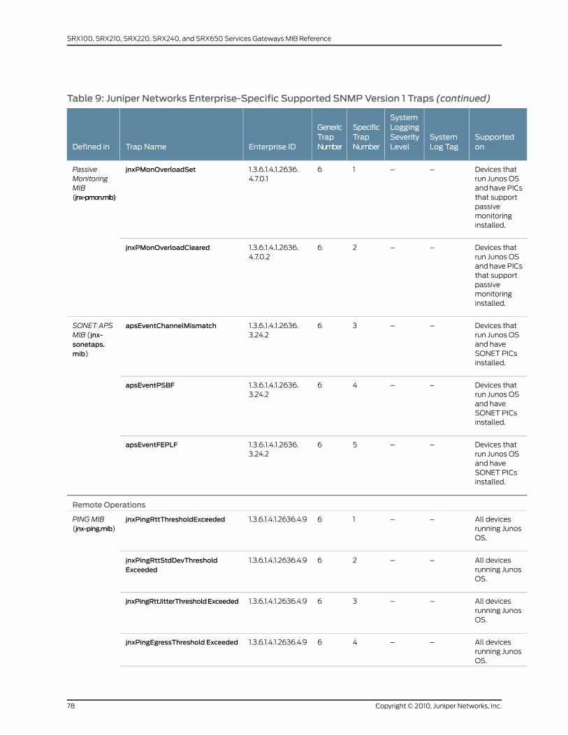
Table 9: Juniper Networks Enterprise-Specific Supported SNMPVersion 1 Traps (continued)
Supportedon
SystemLog Tag
SystemLoggingSeverityLevel
SpecificTrapNumber
GenericTrapNumberEnterprise IDTrap NameDefined in
Devices thatrun Junos OSand have PICsthat supportpassivemonitoringinstalled.
––161.3.6.1.4.1.2636.4.7.0.1
jnxPMonOverloadSetPassiveMonitoringMIB(jnx-pmon.mib)
Devices thatrun Junos OSand have PICsthat supportpassivemonitoringinstalled.
––261.3.6.1.4.1.2636.4.7.0.2
jnxPMonOverloadCleared
Devices thatrun Junos OSand haveSONET PICsinstalled.
––361.3.6.1.4.1.2636.3.24.2
apsEventChannelMismatchSONET APSMIB (jnx-sonetaps.mib)
Devices thatrun Junos OSand haveSONET PICsinstalled.
––461.3.6.1.4.1.2636.3.24.2
apsEventPSBF
Devices thatrun Junos OSand haveSONET PICsinstalled.
––561.3.6.1.4.1.2636.3.24.2
apsEventFEPLF
Remote Operations
All devicesrunning JunosOS.
––161.3.6.1.4.1.2636.4.9jnxPingRttThresholdExceededPINGMIB(jnx-ping.mib)
All devicesrunning JunosOS.
––261.3.6.1.4.1.2636.4.9jnxPingRttStdDevThresholdExceeded
All devicesrunning JunosOS.
––361.3.6.1.4.1.2636.4.9jnxPingRttJitterThresholdExceeded
All devicesrunning JunosOS.
––461.3.6.1.4.1.2636.4.9jnxPingEgressThreshold Exceeded
Copyright © 2010, Juniper Networks, Inc.78
SRX100, SRX210, SRX220, SRX240, and SRX650 Services Gateways MIB Reference
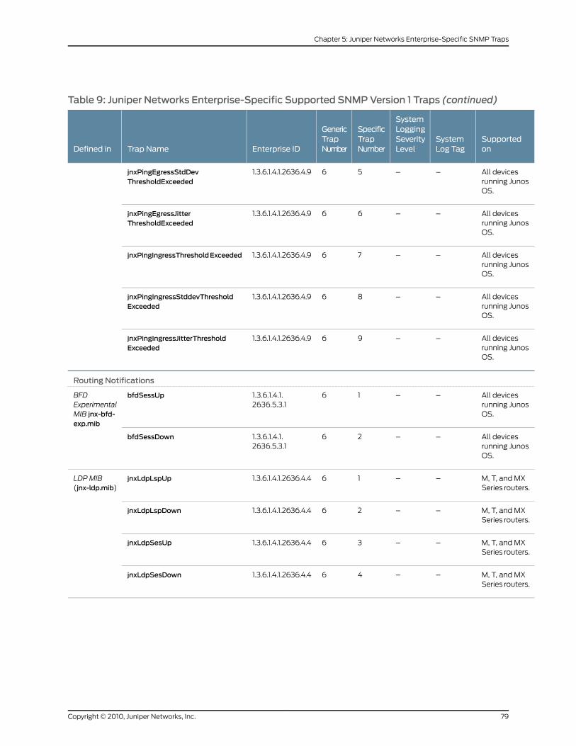
Table 9: Juniper Networks Enterprise-Specific Supported SNMPVersion 1 Traps (continued)
Supportedon
SystemLog Tag
SystemLoggingSeverityLevel
SpecificTrapNumber
GenericTrapNumberEnterprise IDTrap NameDefined in
All devicesrunning JunosOS.
––561.3.6.1.4.1.2636.4.9jnxPingEgressStdDevThresholdExceeded
All devicesrunning JunosOS.
––661.3.6.1.4.1.2636.4.9jnxPingEgressJitterThresholdExceeded
All devicesrunning JunosOS.
––761.3.6.1.4.1.2636.4.9jnxPingIngressThresholdExceeded
All devicesrunning JunosOS.
––861.3.6.1.4.1.2636.4.9jnxPingIngressStddevThresholdExceeded
All devicesrunning JunosOS.
––961.3.6.1.4.1.2636.4.9jnxPingIngressJitterThresholdExceeded
Routing Notifications
All devicesrunning JunosOS.
––161.3.6.1.4.1.2636.5.3.1
bfdSessUpBFDExperimentalMIB jnx-bfd-exp.mib
All devicesrunning JunosOS.
––261.3.6.1.4.1.2636.5.3.1
bfdSessDown
M, T, and MXSeries routers.
––161.3.6.1.4.1.2636.4.4jnxLdpLspUpLDP MIB(jnx-ldp.mib)
M, T, and MXSeries routers.
––261.3.6.1.4.1.2636.4.4jnxLdpLspDown
M, T, and MXSeries routers.
––361.3.6.1.4.1.2636.4.4jnxLdpSesUp
M, T, and MXSeries routers.
––461.3.6.1.4.1.2636.4.4jnxLdpSesDown
79Copyright © 2010, Juniper Networks, Inc.
Chapter 5: Juniper Networks Enterprise-Specific SNMP Traps
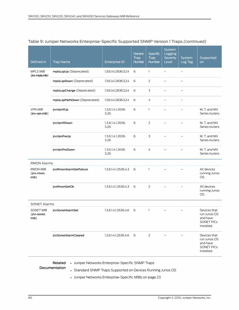
Table 9: Juniper Networks Enterprise-Specific Supported SNMPVersion 1 Traps (continued)
Supportedon
SystemLog Tag
SystemLoggingSeverityLevel
SpecificTrapNumber
GenericTrapNumberEnterprise IDTrap NameDefined in
––161.3.6.1.4.1.2636.3.2.4mplsLspUp (Deprecated)MPLSMIB(jnx-mpls.mib)
––261.3.6.1.4.1.2636.3.2.4mplsLspDown (Deprecated)
––361.3.6.1.4.1.2636.3.2.4mplsLspChange (Deprecated)
––461.3.6.1.4.1.2636.3.2.4mplsLspPathDown (Deprecated)
M, T, and MXSeries routers.
––161.3.6.1.4.1.2636.3.26
jnxVpnIfUpVPNMIB(jnx-vpn.mib)
M, T, and MXSeries routers.
––261.3.6.1.4.1.2636.3.26
jnxVpnIfDown
M, T, and MXSeries routers.
––361.3.6.1.4.1.2636.3.26
jnxVpnPwUp
M, T, and MXSeries routers.
––461.3.6.1.4.1.2636.3.26
jnxVpnPwDown
RMONAlarms
All devicesrunning JunosOS.
––161.3.6.1.4.1.2636.4.3jnxRmonAlarmGetFailureRMONMIB(jnx-rmon.mib)
All devicesrunning JunosOS.
––261.3.6.1.4.1.2636.4.3jnxRmonGetOk
SONET Alarms
Devices thatrun Junos OSand haveSONET PICsinstalled.
––161.3.6.1.4.1.2636.4.6jnxSonetAlarmSetSONETMIB(jnx-sonet.mib)
Devices thatrun Junos OSand haveSONET PICsinstalled.
––261.3.6.1.4.1.2636.4.6jnxSonetAlarmCleared
RelatedDocumentation
Juniper Networks Enterprise-Specific SNMP Traps•
• Standard SNMP Traps Supported on Devices Running Junos OS
• Juniper Networks Enterprise-Specific MIBs on page 23
Copyright © 2010, Juniper Networks, Inc.80
SRX100, SRX210, SRX220, SRX240, and SRX650 Services Gateways MIB Reference
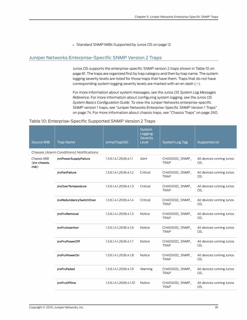
• Standard SNMP MIBs Supported by Junos OS on page 12
Juniper Networks Enterprise-Specific SNMPVersion 2 Traps
Junos OS supports the enterprise-specific SNMP version 2 traps shown in Table 10 on
page 81. The traps are organized first by trap category and then by trap name. The system
logging severity levels are listed for those traps that have them. Traps that do not have
corresponding system logging severity levels are marked with an en dash (–).
For more information about system messages, see the Junos OS System Log Messages
Reference. For more information about configuring system logging, see the Junos OS
System Basics Configuration Guide. To view the Juniper Networks enterprise-specific
SNMP version 1 traps, see “Juniper Networks Enterprise-Specific SNMP Version 1 Traps”
on page 74. For more information about chassis traps, see “Chassis Traps” on page 260.
Table 10: Enterprise-Specific Supported SNMPVersion 2 Traps
Supported onSystem Log Tag
SystemLoggingSeverityLevelsnmpTrapOIDTrap NameSource MIB
Chassis (Alarm Conditions) Notifications
All devices running JunosOS.
CHASSISD_ SNMP_TRAP
Alert1.3.6.1.4.1.2636.4.1.1jnxPowerSupplyFailureChassis MIB(jnx-chassis.mib)
All devices running JunosOS.
CHASSISD_ SNMP_TRAP
Critical1.3.6.1.4.1.2636.4.1.2jnxFanFailure
All devices running JunosOS.
CHASSISD_ SNMP_TRAP
Critical1.3.6.1.4.1.2636.4.1.3jnxOverTemperature
All devices running JunosOS.
CHASSISD_ SNMP_TRAP
Critical1.3.6.1.4.1.2636.4.1.4jnxRedundancySwitchOver
All devices running JunosOS.
CHASSISD_ SNMP_TRAP
Notice1.3.6.1.4.1.2636.4.1.5jnxFruRemoval
All devices running JunosOS.
CHASSISD_ SNMP_TRAP
Notice1.3.6.1.4.1.2636.4.1.6jnxFruInsertion
All devices running JunosOS.
CHASSISD_ SNMP_TRAP
Notice1.3.6.1.4.1.2636.4.1.7jnxFruPowerOff
All devices running JunosOS.
CHASSISD_ SNMP_TRAP
Notice1.3.6.1.4.1.2636.4.1.8jnxFruPowerOn
All devices running JunosOS.
CHASSISD_ SNMP_TRAP
Warning1.3.6.1.4.1.2636.4.1.9jnxFruFailed
All devices running JunosOS.
CHASSISD_ SNMP_TRAP
Notice1.3.6.1.4.1.2636.4.1.10jnxFruOffline
81Copyright © 2010, Juniper Networks, Inc.
Chapter 5: Juniper Networks Enterprise-Specific SNMP Traps
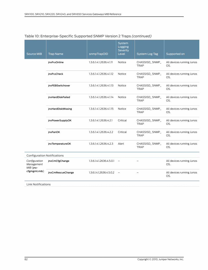
Table 10: Enterprise-Specific Supported SNMPVersion 2 Traps (continued)
Supported onSystem Log Tag
SystemLoggingSeverityLevelsnmpTrapOIDTrap NameSource MIB
All devices running JunosOS.
CHASSISD_ SNMP_TRAP
Notice1.3.6.1.4.1.2636.4.1.11jnxFruOnline
All devices running JunosOS.
CHASSISD_ SNMP_TRAP
Notice1.3.6.1.4.1.2636.4.1.12jnxFruCheck
All devices running JunosOS.
CHASSISD_ SNMP_TRAP
Notice1.3.6.1.4.1.2636.4.1.13jnxFEBSwitchover
All devices running JunosOS.
CHASSISD_ SNMP_TRAP
Notice1.3.6.1.4.1.2636.4.1.14jnxHardDiskFailed
All devices running JunosOS.
CHASSISD_ SNMP_TRAP
Notice1.3.6.1.4.1.2636.4.1.15jnxHardDiskMissing
All devices running JunosOS.
CHASSISD_ SNMP_TRAP
Critical1.3.6.1.4.1.2636.4.2.1jnxPowerSupplyOK
All devices running JunosOS.
CHASSISD_ SNMP_TRAP
Critical1.3.6.1.4.1.2636.4.2.2jnxFanOK
All devices running JunosOS.
CHASSISD_ SNMP_TRAP
Alert1.3.6.1.4.1.2636.4.2.3jnxTemperatureOK
Configuration Notifications
All devices running JunosOS.
––1.3.6.1.4.1.2636.4.5.0.1jnxCmCfgChangeConfigurationManagementMIB (jnx-cfgmgmt.mib) All devices running Junos
OS.––1.3.6.1.4.1.2636.4.5.0.2jnxCmRescueChange
Link Notifications
Copyright © 2010, Juniper Networks, Inc.82
SRX100, SRX210, SRX220, SRX240, and SRX650 Services Gateways MIB Reference
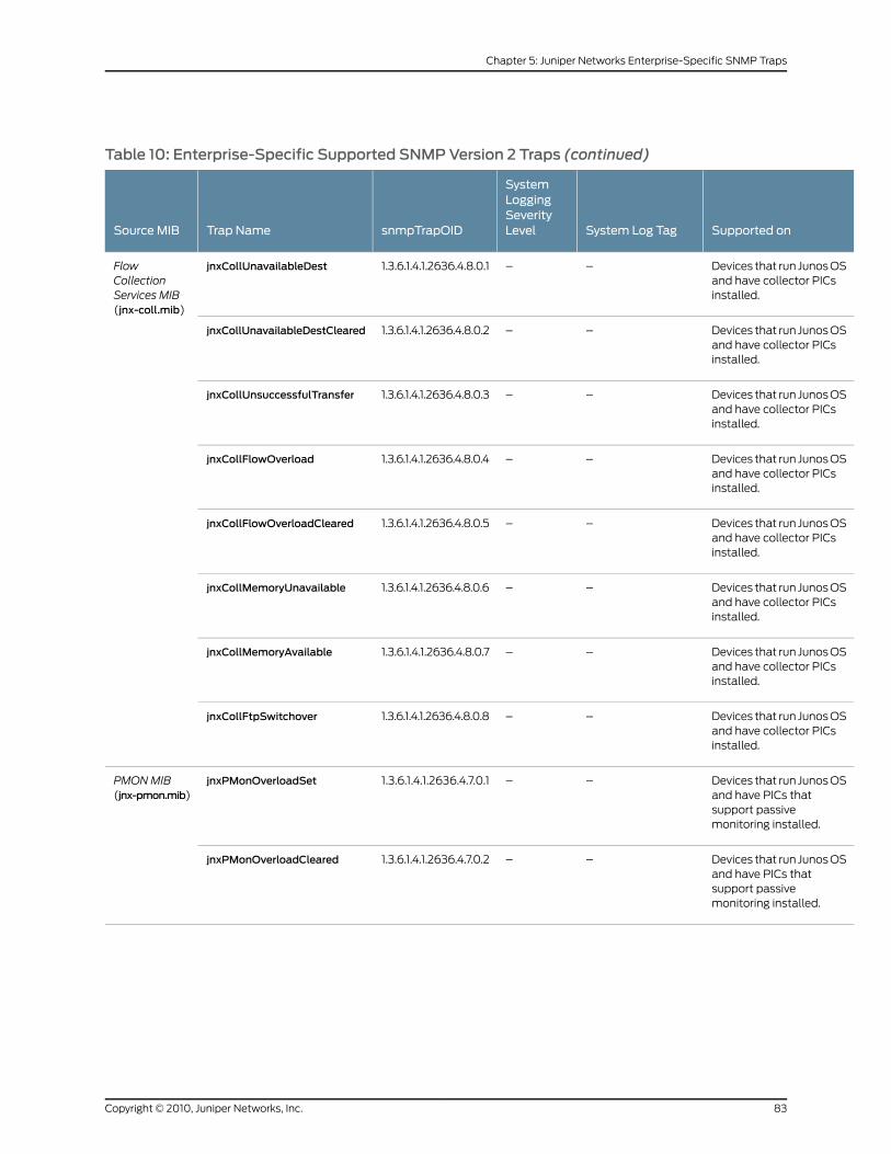
Table 10: Enterprise-Specific Supported SNMPVersion 2 Traps (continued)
Supported onSystem Log Tag
SystemLoggingSeverityLevelsnmpTrapOIDTrap NameSource MIB
Devices that run Junos OSand have collector PICsinstalled.
––1.3.6.1.4.1.2636.4.8.0.1jnxCollUnavailableDestFlowCollectionServices MIB(jnx-coll.mib)
Devices that run Junos OSand have collector PICsinstalled.
––1.3.6.1.4.1.2636.4.8.0.2jnxCollUnavailableDestCleared
Devices that run Junos OSand have collector PICsinstalled.
––1.3.6.1.4.1.2636.4.8.0.3jnxCollUnsuccessfulTransfer
Devices that run Junos OSand have collector PICsinstalled.
––1.3.6.1.4.1.2636.4.8.0.4jnxCollFlowOverload
Devices that run Junos OSand have collector PICsinstalled.
––1.3.6.1.4.1.2636.4.8.0.5jnxCollFlowOverloadCleared
Devices that run Junos OSand have collector PICsinstalled.
––1.3.6.1.4.1.2636.4.8.0.6jnxCollMemoryUnavailable
Devices that run Junos OSand have collector PICsinstalled.
––1.3.6.1.4.1.2636.4.8.0.7jnxCollMemoryAvailable
Devices that run Junos OSand have collector PICsinstalled.
––1.3.6.1.4.1.2636.4.8.0.8jnxCollFtpSwitchover
Devices that run Junos OSand have PICs thatsupport passivemonitoring installed.
––1.3.6.1.4.1.2636.4.7.0.1jnxPMonOverloadSetPMONMIB(jnx-pmon.mib)
Devices that run Junos OSand have PICs thatsupport passivemonitoring installed.
––1.3.6.1.4.1.2636.4.7.0.2jnxPMonOverloadCleared
83Copyright © 2010, Juniper Networks, Inc.
Chapter 5: Juniper Networks Enterprise-Specific SNMP Traps
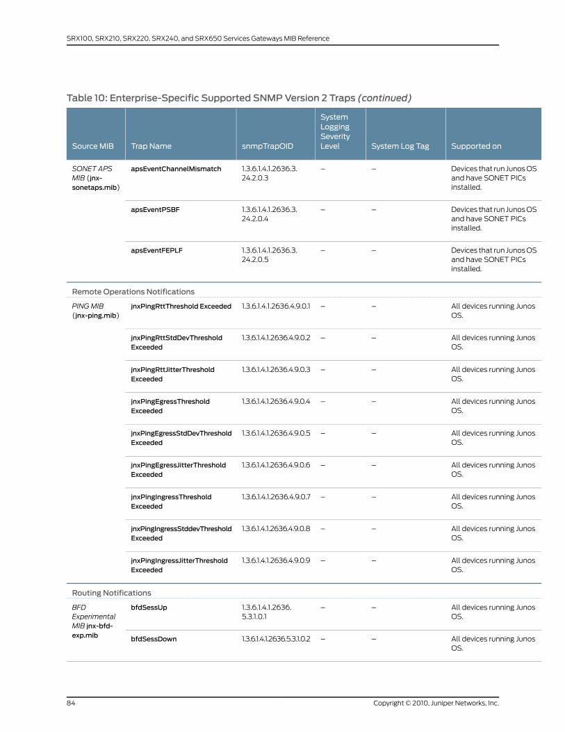
Table 10: Enterprise-Specific Supported SNMPVersion 2 Traps (continued)
Supported onSystem Log Tag
SystemLoggingSeverityLevelsnmpTrapOIDTrap NameSource MIB
Devices that run Junos OSand have SONET PICsinstalled.
––1.3.6.1.4.1.2636.3.24.2.0.3
apsEventChannelMismatchSONET APSMIB (jnx-sonetaps.mib)
Devices that run Junos OSand have SONET PICsinstalled.
––1.3.6.1.4.1.2636.3.24.2.0.4
apsEventPSBF
Devices that run Junos OSand have SONET PICsinstalled.
––1.3.6.1.4.1.2636.3.24.2.0.5
apsEventFEPLF
Remote Operations Notifications
All devices running JunosOS.
––1.3.6.1.4.1.2636.4.9.0.1jnxPingRttThreshold ExceededPINGMIB(jnx-ping.mib)
All devices running JunosOS.
––1.3.6.1.4.1.2636.4.9.0.2jnxPingRttStdDevThresholdExceeded
All devices running JunosOS.
––1.3.6.1.4.1.2636.4.9.0.3jnxPingRttJitterThresholdExceeded
All devices running JunosOS.
––1.3.6.1.4.1.2636.4.9.0.4jnxPingEgressThresholdExceeded
All devices running JunosOS.
––1.3.6.1.4.1.2636.4.9.0.5jnxPingEgressStdDevThresholdExceeded
All devices running JunosOS.
––1.3.6.1.4.1.2636.4.9.0.6jnxPingEgressJitterThresholdExceeded
All devices running JunosOS.
––1.3.6.1.4.1.2636.4.9.0.7jnxPingIngressThresholdExceeded
All devices running JunosOS.
––1.3.6.1.4.1.2636.4.9.0.8jnxPingIngressStddevThresholdExceeded
All devices running JunosOS.
––1.3.6.1.4.1.2636.4.9.0.9jnxPingIngressJitterThresholdExceeded
Routing Notifications
All devices running JunosOS.
––1.3.6.1.4.1.2636.5.3.1.0.1
bfdSessUpBFDExperimentalMIB jnx-bfd-exp.mib All devices running Junos
OS.––1.3.6.1.4.1.2636.5.3.1.0.2bfdSessDown
Copyright © 2010, Juniper Networks, Inc.84
SRX100, SRX210, SRX220, SRX240, and SRX650 Services Gateways MIB Reference
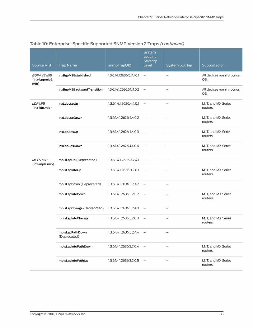
Table 10: Enterprise-Specific Supported SNMPVersion 2 Traps (continued)
Supported onSystem Log Tag
SystemLoggingSeverityLevelsnmpTrapOIDTrap NameSource MIB
All devices running JunosOS.
––1.3.6.1.4.1.2636.5.1.1.1.0.1jnxBgpM2EstablishedBGP4 V2 MIB(jnx-bgpmib2.mib)
All devices running JunosOS.
––1.3.6.1.4.1.2636.5.1.1.1.0.2jnxBgpM2BackwardTransition
M, T, and MX Seriesrouters.
––1.3.6.1.4.1.2626.4.4.0.1jnxLdpLspUpLDP MIB(jnx-ldp.mib)
M, T, and MX Seriesrouters.
––1.3.6.1.4.1.2626.4.4.0.2jnxLdpLspDown
M, T, and MX Seriesrouters.
––1.3.6.1.4.1.2626.4.4.0.3jnxLdpSesUp
M, T, and MX Seriesrouters.
––1.3.6.1.4.1.2626.4.4.0.4jnxLdpSesDown
––1.3.6.1.4.1.2636.3.2.4.1mplsLspUp (Deprecated)MPLSMIB(jnx-mpls.mib)
M, T, and MX Seriesrouters.
––1.3.6.1.4.1.2636.3.2.0.1mplsLspInfoUp
––1.3.6.1.4.1.2636.3.2.4.2mplsLspDown (Deprecated)
M, T, and MX Seriesrouters.
––1.3.6.1.4.1.2636.3.2.0.2mplsLspInfoDown
––1.3.6.1.4.1.2636.3.2.4.3mplsLspChange (Deprecated)
M, T, and MX Seriesrouters.
––1.3.6.1.4.1.2636.3.2.0.3mplsLspInfoChange
––1.3.6.1.4.1.2636.3.2.4.4mplsLspPathDown(Deprecated)
M, T, and MX Seriesrouters.
––1.3.6.1.4.1.2636.3.2.0.4mplsLspInfoPathDown
M, T, and MX Seriesrouters.
––1.3.6.1.4.1.2636.3.2.0.5mplsLspInfoPathUp
85Copyright © 2010, Juniper Networks, Inc.
Chapter 5: Juniper Networks Enterprise-Specific SNMP Traps
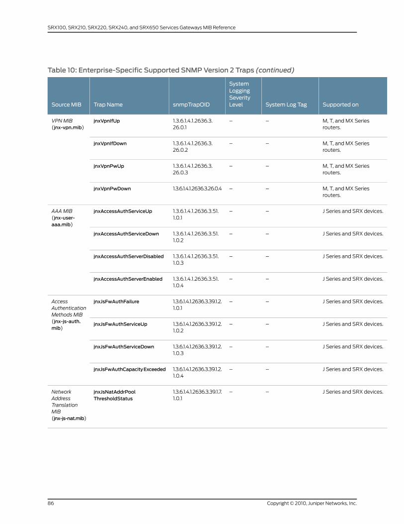
Table 10: Enterprise-Specific Supported SNMPVersion 2 Traps (continued)
Supported onSystem Log Tag
SystemLoggingSeverityLevelsnmpTrapOIDTrap NameSource MIB
M, T, and MX Seriesrouters.
––1.3.6.1.4.1.2636.3.26.0.1
jnxVpnIfUpVPNMIB(jnx-vpn.mib)
M, T, and MX Seriesrouters.
––1.3.6.1.4.1.2636.3.26.0.2
jnxVpnIfDown
M, T, and MX Seriesrouters.
––1.3.6.1.4.1.2636.3.26.0.3
jnxVpnPwUp
M, T, and MX Seriesrouters.
––1.3.6.1.4.1.2636.3.26.0.4jnxVpnPwDown
J Series and SRX devices.––1.3.6.1.4.1.2636.3.51.1.0.1
jnxAccessAuthServiceUpAAAMIB(jnx-user-aaa.mib)
J Series and SRX devices.––1.3.6.1.4.1.2636.3.51.1.0.2
jnxAccessAuthServiceDown
J Series and SRX devices.––1.3.6.1.4.1.2636.3.51.1.0.3
jnxAccessAuthServerDisabled
J Series and SRX devices.––1.3.6.1.4.1.2636.3.51.1.0.4
jnxAccessAuthServerEnabled
J Series and SRX devices.––1.3.6.1.4.1.2636.3.39.1.2.1.0.1
jnxJsFwAuthFailureAccessAuthenticationMethods MIB(jnx-js-auth.mib)
J Series and SRX devices.––1.3.6.1.4.1.2636.3.39.1.2.1.0.2
jnxJsFwAuthServiceUp
J Series and SRX devices.––1.3.6.1.4.1.2636.3.39.1.2.1.0.3
jnxJsFwAuthServiceDown
J Series and SRX devices.––1.3.6.1.4.1.2636.3.39.1.2.1.0.4
jnxJsFwAuthCapacityExceeded
J Series and SRX devices.––1.3.6.1.4.1.2636.3.39.1.7.1.0.1
jnxJsNatAddrPoolThresholdStatus
NetworkAddressTranslationMIB(jnx-js-nat.mib)
Copyright © 2010, Juniper Networks, Inc.86
SRX100, SRX210, SRX220, SRX240, and SRX650 Services Gateways MIB Reference
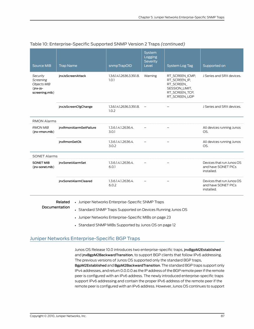
Table 10: Enterprise-Specific Supported SNMPVersion 2 Traps (continued)
Supported onSystem Log Tag
SystemLoggingSeverityLevelsnmpTrapOIDTrap NameSource MIB
J Series and SRX devices.RT_SCREEN_ICMP,RT_SCREEN_IP,RT_SCREEN_SESSION_LIMIT,RT_SCREEN_TCP,RT_SCREEN_UDP
Warning1.3.6.1.4.1.2636.3.39.1.8.1.0.1
jnxJsScreenAttackSecurityScreeningObjects MIB(jnx-js-screening.mib)
J Series and SRX devices.––1.3.6.1.4.1.2636.3.39.1.8.1.0.2
jnxJsScreenCfgChange
RMONAlarms
All devices running JunosOS.
––1.3.6.1.4.1.2636.4.3.0.1
jnxRmonAlarmGetFailureRMONMIB(jnx-rmon.mib)
All devices running JunosOS.
––1.3.6.1.4.1.2636.4.3.0.2
jnxRmonGetOk
SONET Alarms
Devices that run Junos OSand have SONET PICsinstalled.
––1.3.6.1.4.1.2636.4.6.0.1
jnxSonetAlarmSetSONETMIB(jnx-sonet.mib)
Devices that run Junos OSand have SONET PICsinstalled.
––1.3.6.1.4.1.2636.4.6.0.2
jnxSonetAlarmCleared
RelatedDocumentation
Juniper Networks Enterprise-Specific SNMP Traps•
• Standard SNMP Traps Supported on Devices Running Junos OS
• Juniper Networks Enterprise-Specific MIBs on page 23
• Standard SNMP MIBs Supported by Junos OS on page 12
Juniper Networks Enterprise-Specific BGP Traps
Junos OS Release 10.0 introduces two enterprise-specific traps, jnxBgpM2Established
and jnxBgpM2BackwardTransition, to support BGP clients that follow IPv6 addressing.
The previous versions of Junos OS supported only the standard BGP traps,
BgpM2Established andBgpM2BackwardTransition. The standard BGP traps support only
IPv4 addresses, and return 0.0.0.0 as the IP address of the BGP remote peer if the remote
peer is configured with an IPv6 address. The newly introduced enterprise-specific traps
support IPv6 addressing and contain the proper IPv6 address of the remote peer if the
remote peer is configured with an IPv6 address. However, Junos OS continues to support
87Copyright © 2010, Juniper Networks, Inc.
Chapter 5: Juniper Networks Enterprise-Specific SNMP Traps
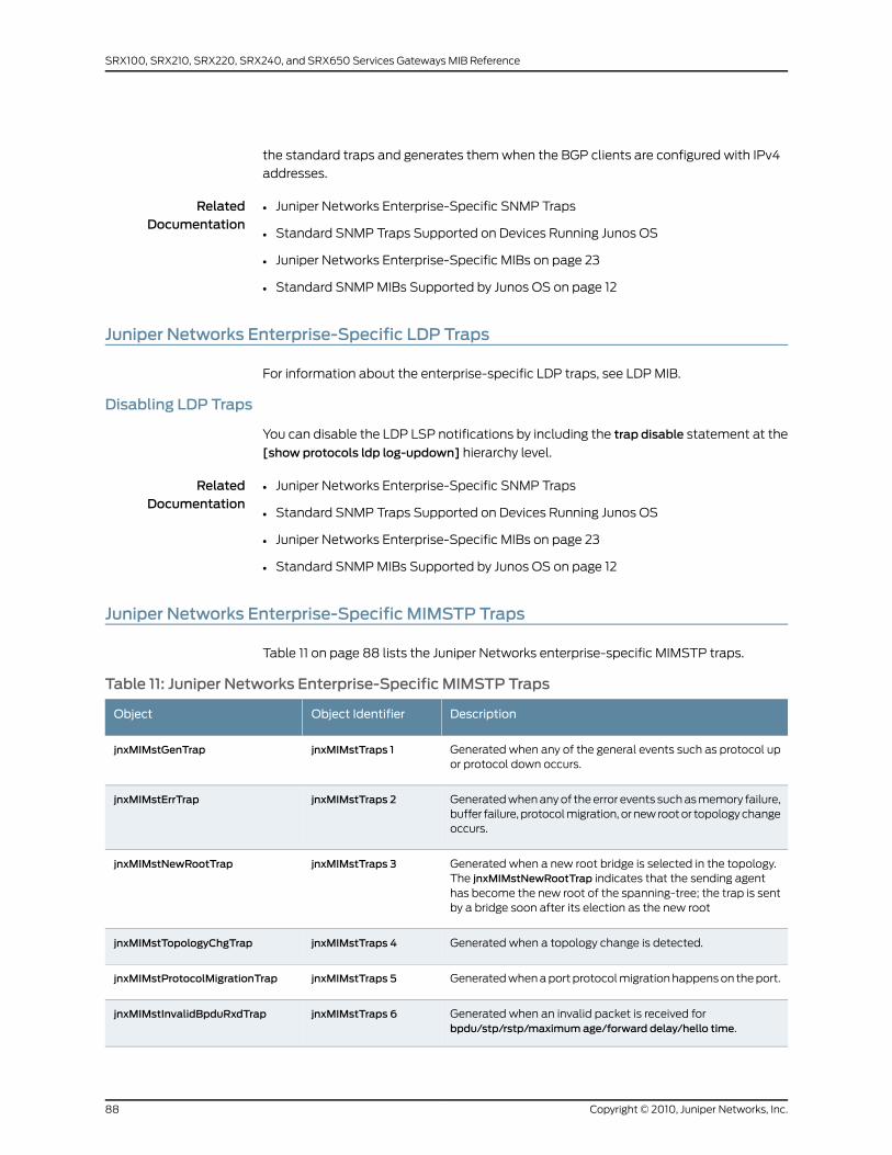
the standard traps and generates them when the BGP clients are configured with IPv4
addresses.
RelatedDocumentation
Juniper Networks Enterprise-Specific SNMP Traps•
• Standard SNMP Traps Supported on Devices Running Junos OS
• Juniper Networks Enterprise-Specific MIBs on page 23
• Standard SNMP MIBs Supported by Junos OS on page 12
Juniper Networks Enterprise-Specific LDP Traps
For information about the enterprise-specific LDP traps, see LDP MIB.
Disabling LDP Traps
You can disable the LDP LSP notifications by including the trap disable statement at the
[show protocols ldp log-updown] hierarchy level.
RelatedDocumentation
Juniper Networks Enterprise-Specific SNMP Traps•
• Standard SNMP Traps Supported on Devices Running Junos OS
• Juniper Networks Enterprise-Specific MIBs on page 23
• Standard SNMP MIBs Supported by Junos OS on page 12
Juniper Networks Enterprise-Specific MIMSTP Traps
Table 11 on page 88 lists the Juniper Networks enterprise-specific MIMSTP traps.
Table 11: Juniper Networks Enterprise-Specific MIMSTP Traps
DescriptionObject IdentifierObject
Generated when any of the general events such as protocol upor protocol down occurs.
jnxMIMstTraps 1jnxMIMstGenTrap
Generated when any of the error events such as memory failure,buffer failure, protocol migration, or new root or topology changeoccurs.
jnxMIMstTraps 2jnxMIMstErrTrap
Generated when a new root bridge is selected in the topology.The jnxMIMstNewRootTrap indicates that the sending agenthas become the new root of the spanning-tree; the trap is sentby a bridge soon after its election as the new root
jnxMIMstTraps 3jnxMIMstNewRootTrap
Generated when a topology change is detected.jnxMIMstTraps 4jnxMIMstTopologyChgTrap
Generated when a port protocol migration happens on the port.jnxMIMstTraps 5jnxMIMstProtocolMigrationTrap
Generated when an invalid packet is received forbpdu/stp/rstp/maximum age/forward delay/hello time.
jnxMIMstTraps 6jnxMIMstInvalidBpduRxdTrap
Copyright © 2010, Juniper Networks, Inc.88
SRX100, SRX210, SRX220, SRX240, and SRX650 Services Gateways MIB Reference
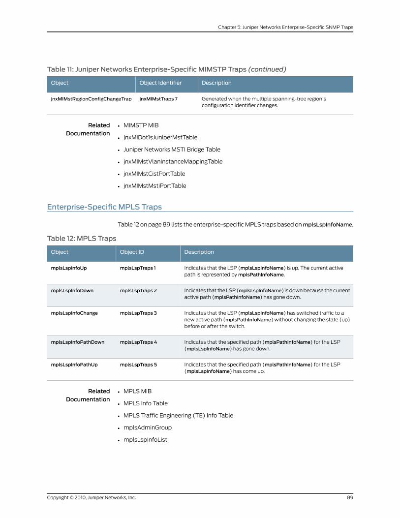
Table 11: Juniper Networks Enterprise-Specific MIMSTP Traps (continued)
DescriptionObject IdentifierObject
Generated when the multiple spanning-tree region'sconfiguration identifier changes.
jnxMIMstTraps 7jnxMIMstRegionConfigChangeTrap
RelatedDocumentation
MIMSTP MIB•
• jnxMIDot1sJuniperMstTable
• Juniper Networks MSTI Bridge Table
• jnxMIMstVlanInstanceMappingTable
• jnxMIMstCistPortTable
• jnxMIMstMstiPortTable
Enterprise-Specific MPLS Traps
Table 12 on page 89 lists the enterprise-specific MPLS traps based onmplsLspInfoName.
Table 12: MPLS Traps
DescriptionObject IDObject
Indicates that the LSP (mplsLspInfoName) is up. The current activepath is represented by mplsPathInfoName.
mplsLspTraps 1mplsLspInfoUp
Indicates that the LSP (mplsLspInfoName) is down because the currentactive path (mplsPathInfoName) has gone down.
mplsLspTraps 2mplsLspInfoDown
Indicates that the LSP (mplsLspInfoName) has switched traffic to anew active path (mplsPathInfoName) without changing the state (up)before or after the switch.
mplsLspTraps 3mplsLspInfoChange
Indicates that the specified path (mplsPathInfoName) for the LSP(mplsLspInfoName) has gone down.
mplsLspTraps 4mplsLspInfoPathDown
Indicates that the specified path (mplsPathInfoName) for the LSP(mplsLspInfoName) has come up.
mplsLspTraps 5mplsLspInfoPathUp
RelatedDocumentation
MPLS MIB•
• MPLS Info Table
• MPLS Traffic Engineering (TE) Info Table
• mplsAdminGroup
• mplsLspInfoList
89Copyright © 2010, Juniper Networks, Inc.
Chapter 5: Juniper Networks Enterprise-Specific SNMP Traps
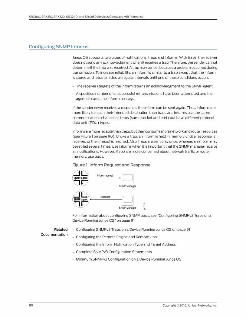
Configuring SNMP Informs
Junos OS supports two types of notifications: traps and informs. With traps, the receiver
does not send any acknowledgment when it receives a trap. Therefore, the sender cannot
determine if the trap was received. A trap may be lost because a problem occurred during
transmission. To increase reliability, an inform is similar to a trap except that the inform
is stored and retransmitted at regular intervals until one of these conditions occurs:
• The receiver (target) of the inform returns an acknowledgment to the SNMP agent.
• A specified number of unsuccessful retransmissions have been attempted and the
agent discards the inform message.
If the sender never receives a response, the inform can be sent again. Thus, informs are
more likely to reach their intended destination than traps are. Informs use the same
communications channel as traps (same socket and port) but have different protocol
data unit (PDU) types.
Informs are more reliable than traps, but they consume more network and router resources
(see Figure 1 on page 90). Unlike a trap, an inform is held in memory until a response is
received or the timeout is reached. Also, traps are sent only once, whereas an inform may
be retried several times. Use informs when it is important that the SNMP manager receive
all notifications. However, if you are more concerned about network traffic or router
memory, use traps.
Figure 1: Inform Request and Response
For information about configuring SNMP traps, see “Configuring SNMPv3 Traps on a
Device Running Junos OS” on page 91.
RelatedDocumentation
Configuring SNMPv3 Traps on a Device Running Junos OS on page 91•
• Configuring the Remote Engine and Remote User
• Configuring the Inform Notification Type and Target Address
• Complete SNMPv3 Configuration Statements
• Minimum SNMPv3 Configuration on a Device Running Junos OS
Copyright © 2010, Juniper Networks, Inc.90
SRX100, SRX210, SRX220, SRX240, and SRX650 Services Gateways MIB Reference
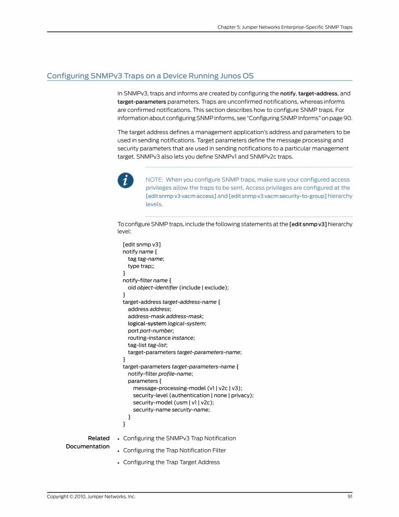
Configuring SNMPv3 Traps on a Device Running Junos OS
In SNMPv3, traps and informs are created by configuring the notify, target-address, and
target-parameters parameters. Traps are unconfirmed notifications, whereas informs
are confirmed notifications. This section describes how to configure SNMP traps. For
information about configuring SNMP informs, see “Configuring SNMP Informs” on page 90.
The target address defines a management application’s address and parameters to be
used in sending notifications. Target parameters define the message processing and
security parameters that are used in sending notifications to a particular management
target. SNMPv3 also lets you define SNMPv1 and SNMPv2c traps.
NOTE: When you configure SNMP traps, make sure your configured accessprivileges allow the traps to be sent. Access privileges are configured at the[editsnmpv3vacmaccess]and [editsnmpv3vacmsecurity-to-group]hierarchy
levels.
To configure SNMP traps, include the following statements at the [edit snmpv3]hierarchylevel:
[edit snmp v3]notify name {tag tag-name;type trap;;
}notify-filter name {oid object-identifier (include | exclude);
}target-address target-address-name {address address;address-mask address-mask;logical-system logical-system;port port-number;routing-instance instance;tag-list tag-list;target-parameters target-parameters-name;
}target-parameters target-parameters-name {notify-filter profile-name;parameters {message-processing-model (v1 | v2c | v3);security-level (authentication | none | privacy);security-model (usm | v1 | v2c);security-name security-name;
}}
RelatedDocumentation
• Configuring the SNMPv3 Trap Notification
• Configuring the Trap Notification Filter
• Configuring the Trap Target Address
91Copyright © 2010, Juniper Networks, Inc.
Chapter 5: Juniper Networks Enterprise-Specific SNMP Traps

• Defining and Configuring the Trap Target Parameters
• Configuring SNMP Informs on page 90
• Configuring the Remote Engine and Remote User
• Configuring the Inform Notification Type and Target Address
• Complete SNMPv3 Configuration Statements
• Minimum SNMPv3 Configuration on a Device Running Junos OS
Copyright © 2010, Juniper Networks, Inc.92
SRX100, SRX210, SRX220, SRX240, and SRX650 Services Gateways MIB Reference
CHAPTER 6
Summary of SNMP ConfigurationStatements
The following sections explain each of the SNMP configuration statements. The
statements are organized alphabetically.
access-list
Syntax [edit snmp]routing-instance-access {access-list {routing-instance;routing-instance restrict;
}}
Hierarchy Level [edit snmp routing-instance-access]
Release Information Statement introduced in Junos OS Release 8.4.
Description Create access lists to control SNMP agents in routing instances from accessing SNMP
information. To enable the SNMP agent on a routing instance to access SNMP information,
specify the routing instance name. To disable the SNMP agent on a routing instance from
accessing SNMP information, include the routing-instance name followed by the restrict
keyword.
Required PrivilegeLevel
snmp—To view this statement in the configuration.
snmp-control—To add this statement to the configuration.
RelatedDocumentation
• routing-instance-access on page 107
93Copyright © 2010, Juniper Networks, Inc.
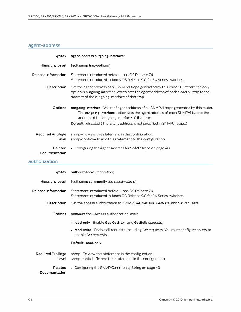
agent-address
Syntax agent-address outgoing-interface;
Hierarchy Level [edit snmp trap-options]
Release Information Statement introduced before Junos OS Release 7.4.
Statement introduced in Junos OS Release 9.0 for EX Series switches.
Description Set the agent address of all SNMPv1 traps generated by this router. Currently, the only
option is outgoing-interface, which sets the agent address of each SNMPv1 trap to the
address of the outgoing interface of that trap.
Options outgoing-interface—Value of agent address of all SNMPv1 traps generated by this router.
The outgoing-interface option sets the agent address of each SNMPv1 trap to the
address of the outgoing interface of that trap.
Default: disabled (The agent address is not specified in SNMPv1 traps.)
Required PrivilegeLevel
snmp—To view this statement in the configuration.
snmp-control—To add this statement to the configuration.
RelatedDocumentation
• Configuring the Agent Address for SNMP Traps on page 48
authorization
Syntax authorization authorization;
Hierarchy Level [edit snmp community community-name]
Release Information Statement introduced before Junos OS Release 7.4.
Statement introduced in Junos OS Release 9.0 for EX Series switches.
Description Set the access authorization for SNMP Get, GetBulk, GetNext, and Set requests.
Options authorization—Access authorization level:
• read-only—Enable Get, GetNext, and GetBulk requests.
• read-write—Enable all requests, including Set requests. You must configure a view to
enable Set requests.
Default: read-only
Required PrivilegeLevel
snmp—To view this statement in the configuration.
snmp-control—To add this statement to the configuration.
RelatedDocumentation
• Configuring the SNMP Community String on page 43
Copyright © 2010, Juniper Networks, Inc.94
SRX100, SRX210, SRX220, SRX240, and SRX650 Services Gateways MIB Reference
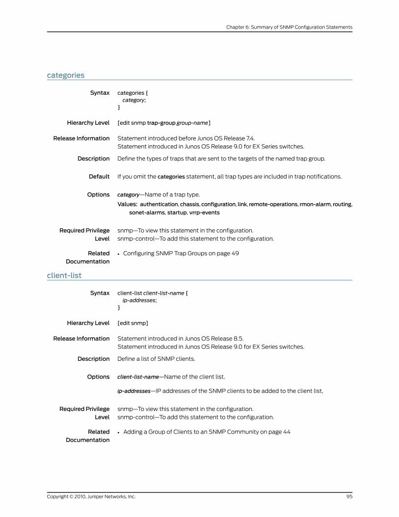
categories
Syntax categories {category;
}
Hierarchy Level [edit snmp trap-group group-name]
Release Information Statement introduced before Junos OS Release 7.4.
Statement introduced in Junos OS Release 9.0 for EX Series switches.
Description Define the types of traps that are sent to the targets of the named trap group.
Default If you omit the categories statement, all trap types are included in trap notifications.
Options category—Name of a trap type.
Values: authentication,chassis,configuration, link, remote-operations, rmon-alarm, routing,
sonet-alarms, startup, vrrp-events
Required PrivilegeLevel
snmp—To view this statement in the configuration.
snmp-control—To add this statement to the configuration.
RelatedDocumentation
• Configuring SNMP Trap Groups on page 49
client-list
Syntax client-list client-list-name {ip-addresses;
}
Hierarchy Level [edit snmp]
Release Information Statement introduced in Junos OS Release 8.5.
Statement introduced in Junos OS Release 9.0 for EX Series switches.
Description Define a list of SNMP clients.
Options client-list-name—Name of the client list.
ip-addresses—IP addresses of the SNMP clients to be added to the client list,
Required PrivilegeLevel
snmp—To view this statement in the configuration.
snmp-control—To add this statement to the configuration.
RelatedDocumentation
• Adding a Group of Clients to an SNMP Community on page 44
95Copyright © 2010, Juniper Networks, Inc.
Chapter 6: Summary of SNMP Configuration Statements
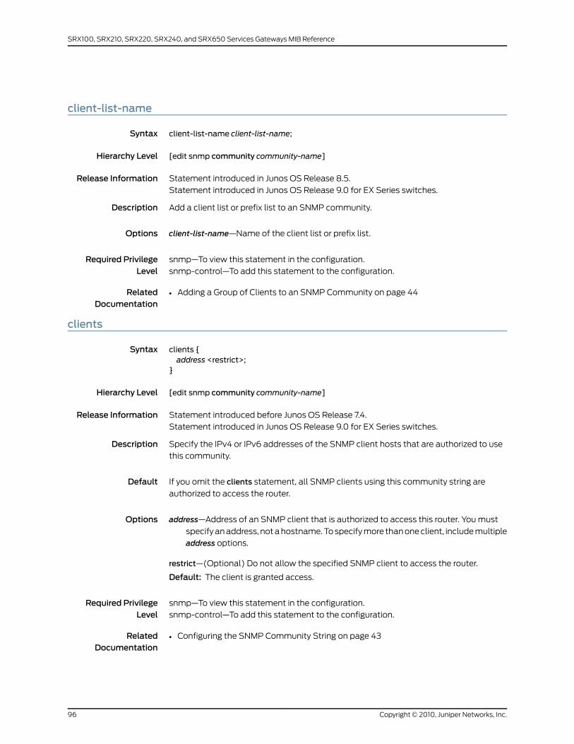
client-list-name
Syntax client-list-name client-list-name;
Hierarchy Level [edit snmp community community-name]
Release Information Statement introduced in Junos OS Release 8.5.
Statement introduced in Junos OS Release 9.0 for EX Series switches.
Description Add a client list or prefix list to an SNMP community.
Options client-list-name—Name of the client list or prefix list.
Required PrivilegeLevel
snmp—To view this statement in the configuration.
snmp-control—To add this statement to the configuration.
RelatedDocumentation
• Adding a Group of Clients to an SNMP Community on page 44
clients
Syntax clients {address <restrict>;
}
Hierarchy Level [edit snmp community community-name]
Release Information Statement introduced before Junos OS Release 7.4.
Statement introduced in Junos OS Release 9.0 for EX Series switches.
Description Specify the IPv4 or IPv6 addresses of the SNMP client hosts that are authorized to use
this community.
Default If you omit the clients statement, all SNMP clients using this community string are
authorized to access the router.
Options address—Address of an SNMP client that is authorized to access this router. You must
specify an address, not a hostname. To specify more than one client, include multiple
address options.
restrict—(Optional) Do not allow the specified SNMP client to access the router.
Default: The client is granted access.
Required PrivilegeLevel
snmp—To view this statement in the configuration.
snmp-control—To add this statement to the configuration.
RelatedDocumentation
• Configuring the SNMP Community String on page 43
Copyright © 2010, Juniper Networks, Inc.96
SRX100, SRX210, SRX220, SRX240, and SRX650 Services Gateways MIB Reference
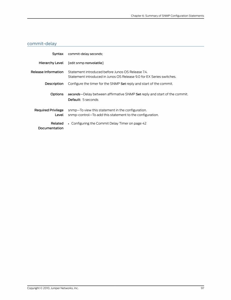
commit-delay
Syntax commit-delay seconds;
Hierarchy Level [edit snmp nonvolatile]
Release Information Statement introduced before Junos OS Release 7.4.
Statement introduced in Junos OS Release 9.0 for EX Series switches.
Description Configure the timer for the SNMP Set reply and start of the commit.
Options seconds—Delay between affirmative SNMP Set reply and start of the commit.
Default: 5 seconds
Required PrivilegeLevel
snmp—To view this statement in the configuration.
snmp-control—To add this statement to the configuration.
RelatedDocumentation
• Configuring the Commit Delay Timer on page 42
97Copyright © 2010, Juniper Networks, Inc.
Chapter 6: Summary of SNMP Configuration Statements
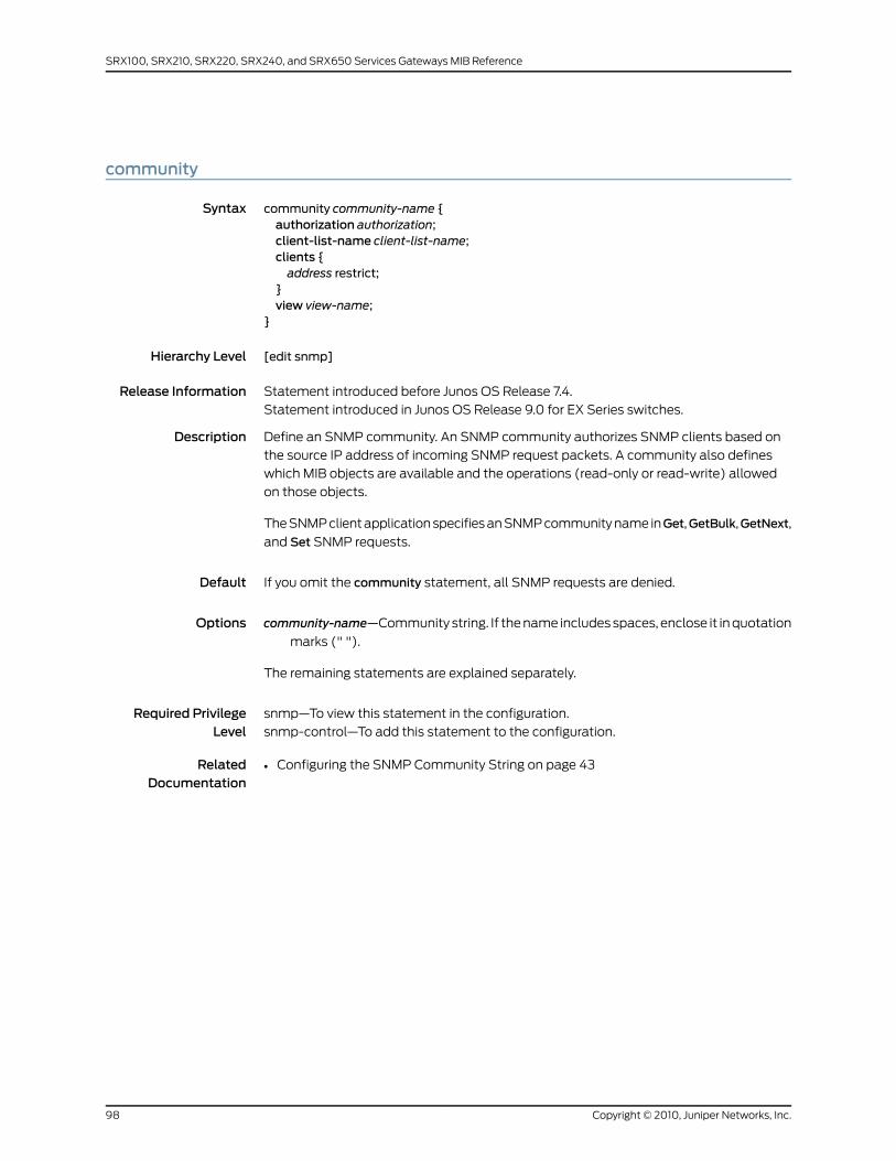
community
Syntax community community-name {authorization authorization;client-list-name client-list-name;clients {address restrict;
}view view-name;
}
Hierarchy Level [edit snmp]
Release Information Statement introduced before Junos OS Release 7.4.
Statement introduced in Junos OS Release 9.0 for EX Series switches.
Description Define an SNMP community. An SNMP community authorizes SNMP clients based on
the source IP address of incoming SNMP request packets. A community also defines
which MIB objects are available and the operations (read-only or read-write) allowed
on those objects.
The SNMP client application specifies an SNMP community name inGet,GetBulk,GetNext,
and Set SNMP requests.
Default If you omit the community statement, all SNMP requests are denied.
Options community-name—Community string. If the name includes spaces, enclose it in quotation
marks (" ").
The remaining statements are explained separately.
Required PrivilegeLevel
snmp—To view this statement in the configuration.
snmp-control—To add this statement to the configuration.
RelatedDocumentation
• Configuring the SNMP Community String on page 43
Copyright © 2010, Juniper Networks, Inc.98
SRX100, SRX210, SRX220, SRX240, and SRX650 Services Gateways MIB Reference
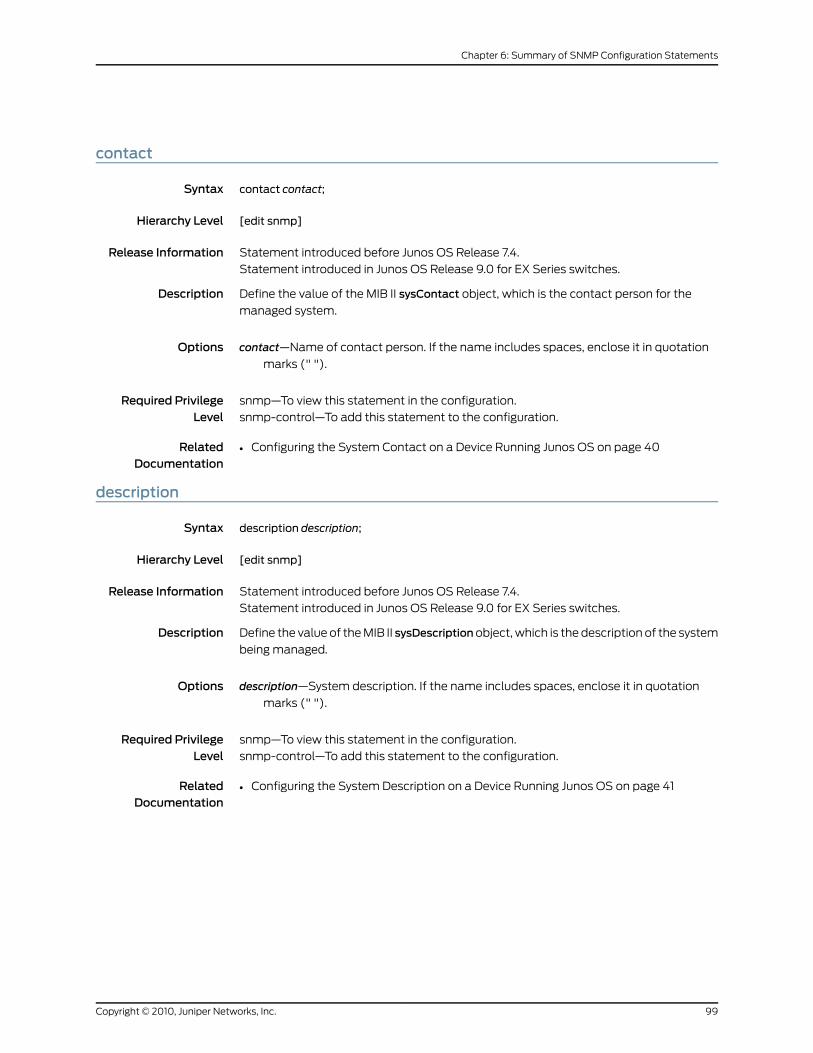
contact
Syntax contact contact;
Hierarchy Level [edit snmp]
Release Information Statement introduced before Junos OS Release 7.4.
Statement introduced in Junos OS Release 9.0 for EX Series switches.
Description Define the value of the MIB II sysContact object, which is the contact person for the
managed system.
Options contact—Name of contact person. If the name includes spaces, enclose it in quotation
marks (" ").
Required PrivilegeLevel
snmp—To view this statement in the configuration.
snmp-control—To add this statement to the configuration.
RelatedDocumentation
• Configuring the System Contact on a Device Running Junos OS on page 40
description
Syntax description description;
Hierarchy Level [edit snmp]
Release Information Statement introduced before Junos OS Release 7.4.
Statement introduced in Junos OS Release 9.0 for EX Series switches.
Description Define the value of the MIB II sysDescriptionobject, which is the description of the system
being managed.
Options description—System description. If the name includes spaces, enclose it in quotation
marks (" ").
Required PrivilegeLevel
snmp—To view this statement in the configuration.
snmp-control—To add this statement to the configuration.
RelatedDocumentation
• Configuring the System Description on a Device Running Junos OS on page 41
99Copyright © 2010, Juniper Networks, Inc.
Chapter 6: Summary of SNMP Configuration Statements
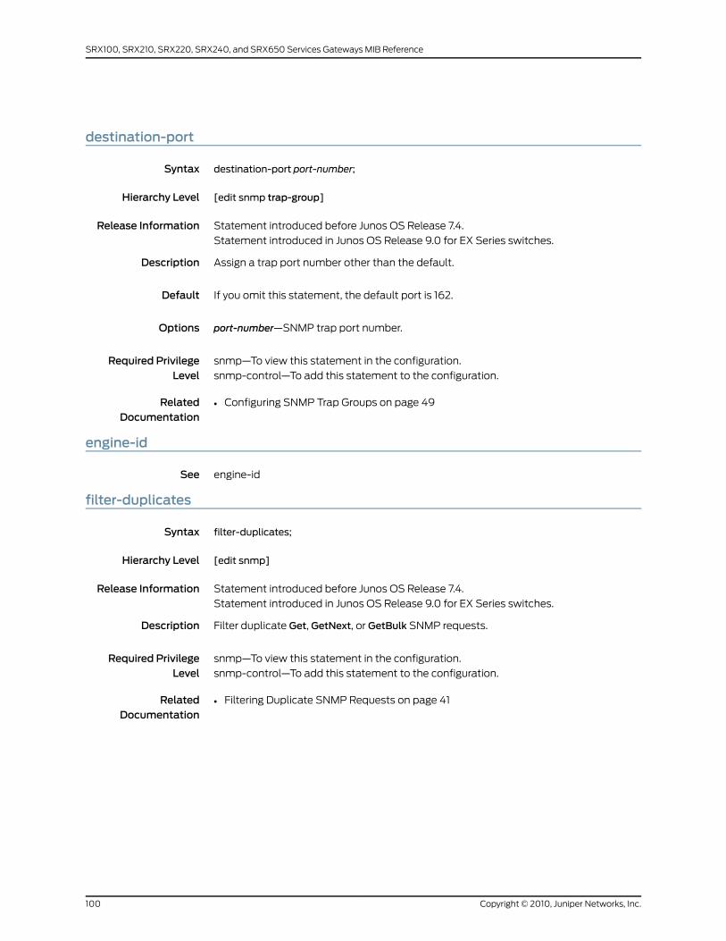
destination-port
Syntax destination-port port-number;
Hierarchy Level [edit snmp trap-group]
Release Information Statement introduced before Junos OS Release 7.4.
Statement introduced in Junos OS Release 9.0 for EX Series switches.
Description Assign a trap port number other than the default.
Default If you omit this statement, the default port is 162.
Options port-number—SNMP trap port number.
Required PrivilegeLevel
snmp—To view this statement in the configuration.
snmp-control—To add this statement to the configuration.
RelatedDocumentation
• Configuring SNMP Trap Groups on page 49
engine-id
See engine-id
filter-duplicates
Syntax filter-duplicates;
Hierarchy Level [edit snmp]
Release Information Statement introduced before Junos OS Release 7.4.
Statement introduced in Junos OS Release 9.0 for EX Series switches.
Description Filter duplicate Get, GetNext, or GetBulk SNMP requests.
Required PrivilegeLevel
snmp—To view this statement in the configuration.
snmp-control—To add this statement to the configuration.
RelatedDocumentation
• Filtering Duplicate SNMP Requests on page 41
Copyright © 2010, Juniper Networks, Inc.100
SRX100, SRX210, SRX220, SRX240, and SRX650 Services Gateways MIB Reference
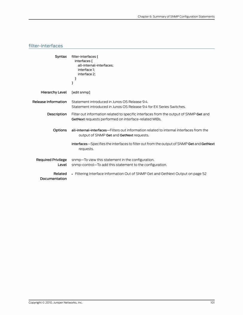
filter-interfaces
Syntax filter-interfaces {interfaces {all-internal-interfaces;interface 1;interface 2;
}}
Hierarchy Level [edit snmp]
Release Information Statement introduced in Junos OS Release 9.4.
Statement introduced in Junos OS Release 9.4 for EX Series Switches.
Description Filter out information related to specific interfaces from the output of SNMP Get and
GetNext requests performed on interface-related MIBs.
Options all-internal-interfaces—Filters out information related to internal interfaces from the
output of SNMP Get and GetNext requests.
interfaces—Specifies the interfaces to filter out from the output of SNMPGetandGetNext
requests.
Required PrivilegeLevel
snmp—To view this statement in the configuration.
snmp-control—To add this statement to the configuration.
RelatedDocumentation
• Filtering Interface Information Out of SNMP Get and GetNext Output on page 52
101Copyright © 2010, Juniper Networks, Inc.
Chapter 6: Summary of SNMP Configuration Statements

interface
Syntax interface [ interface-names ];
Hierarchy Level [edit snmp]
Release Information Statement introduced before Junos OS Release 7.4.
Statement introduced in Junos OS Release 9.0 for EX Series switches.
Description Configure the interfaces on which SNMP requests can be accepted.
Default If you omit this statement, SNMP requests entering the router through any interface are
accepted.
Options interface-names—Names of one or more logical interfaces.
Required PrivilegeLevel
snmp—To view this statement in the configuration.
snmp-control—To add this statement to the configuration.
RelatedDocumentation
• Configuring the Interfaces on Which SNMP Requests Can Be Accepted on page 52
location
Syntax location location;
Hierarchy Level [edit snmp]
Release Information Statement introduced before Junos OS Release 7.4.
Statement introduced in Junos OS Release 9.0 for EX Series switches.
Description Define the value of the MIB II sysLocation object, which is the physical location of the
managed system.
Options location—Location of the local system. You must enclose the name within quotation
marks (" ").
Required PrivilegeLevel
snmp—To view this statement in the configuration.
snmp-control—To add this statement to the configuration.
RelatedDocumentation
• Configuring the System Location for a Device Running Junos OS on page 40
Copyright © 2010, Juniper Networks, Inc.102
SRX100, SRX210, SRX220, SRX240, and SRX650 Services Gateways MIB Reference
logical-system
Syntax logical-system logical-system-name {routing-instance routing-instance-name;
}
Hierarchy Level [edit snmp community community-name],[edit snmp trap-group],[edit snmp trap-options][edit snmp v3target-address target-address-name]
Release Information Statement introduced in Junos OS Release 9.3
Statement introduced in Junos OS Release 9.0 for EX Series switches.
NOTE: The logical-system statement replaces the logical-router statement,
and is backward-compatible with Junos OS Release 8.3 and later.
Description Specify a logical system name for SNMP v1 and v2c clients.
Include at the [editsnmptrap-options]hierarchy level to specify a logical-system address
as the source address of an SNMP trap.
Include at the [edit snmp v3 target-address] hierarchy level to specify a logical-system
name as the destination address for an SNMPv3 trap or inform.
Options logical-system-name–Name of the logical system.
routing-instance routing-instance-name–Statement to specify a routing instance associated
with the logical system.
Required PrivilegeLevel
snmp—To view this statement in the configuration.
snmp-control—To add this statement to the configuration.
RelatedDocumentation
• Specifying a Routing Instance in an SNMPv1 or SNMPv2c Community on page 131
• Configuring the Trap Target Address
103Copyright © 2010, Juniper Networks, Inc.
Chapter 6: Summary of SNMP Configuration Statements
logical-system-trap-filter
Syntax logical-system-trap-filter;
Hierarchy Level [edit snmp]
Release Information Statement introduced in Junos OS Release 8.4.
Description Restrict the routing instances from receiving traps that are not related to the logical
system networks to which they belong.
Required PrivilegeLevel
snmp—To view this statement in the configuration.
snmp-control—To add this statement to the configuration.
RelatedDocumentation
• Trap Support for Routing Instances on page 134
name
Syntax name name;
Hierarchy Level [edit snmp]
Release Information Statement introduced before Junos OS Release 7.4.
Statement introduced in Junos OS Release 9.0 for EX Series switches.
Description Set the system name from the command-line interface.
Options name—System name override.
Required PrivilegeLevel
snmp—To view this statement in the configuration.
snmp-control—To add this statement to the configuration.
RelatedDocumentation
• Configuring the System Name on page 42
Copyright © 2010, Juniper Networks, Inc.104
SRX100, SRX210, SRX220, SRX240, and SRX650 Services Gateways MIB Reference
nonvolatile
Syntax nonvolatile {commit-delay seconds;
}
Hierarchy Level [edit snmp]
Release Information Statement introduced before Junos OS Release 7.4.
The commit-delay statement introduced in Junos OS Release 9.0 for EX Series switches.
Description Configure options for SNMP Set requests.
The statement is explained separately.
Required PrivilegeLevel
snmp—To view this statement in the configuration.
snmp-control—To add this statement to the configuration.
RelatedDocumentation
• Configuring the Commit Delay Timer on page 42
• commit-delay on page 97
oid
Syntax oid object-identifier ( exclude| include );
Hierarchy Level [edit snmp view view-name]
Release Information Statement introduced before Junos OS Release 7.4.
Statement introduced in Junos OS Release 9.0 for EX Series switches.
Description Specify an object identifier (OID) used to represent a subtree of MIB objects.
Options exclude—Exclude the subtree of MIB objects represented by the specified OID.
include—Include the subtree of MIB objects represented by the specified OID.
object-identifier—OID used to represent a subtree of MIB objects. All MIB objects
represented by this statement have the specified OID as a prefix. You can specify
the OID using either a sequence of dotted integers or a subtree name.
Required PrivilegeLevel
snmp—To view this statement in the configuration.
snmp-control—To add this statement to the configuration.
RelatedDocumentation
• Configuring MIB Views on page 53
105Copyright © 2010, Juniper Networks, Inc.
Chapter 6: Summary of SNMP Configuration Statements
routing-instance
Syntax routing-instance routing-instance-name;
Hierarchy Level [edit snmp community community-name],[edit snmp community community-name logical-system logical-system-name],[edit snmp trap-group group]
Release Information Statement introduced in Junos OS Release 8.3.
Added to the [edit snmp community community-name] hierarchy level in Junos OS
Release 8.4.
Added to the [editsnmpcommunitycommunity-name logical-system logical-system-name]
hierarchy level in Junos OS Release 9.1.
Statement introduced in Junos OS Release 9.1 for EX Series switches.
Description Specify a routing instance for SNMPv1 and SNMPv2 trap targets. All targets configured
in the trap group use this routing instance.
If the routing instance is defined within a logical system, include the logical-system
logical-system-name statement at the [editsnmpcommunitycommunity-name]hierarchy
level and specify the routing-instance statement under the [edit snmp community
community-name logical-system logical system-name] hierarchy level.
Options routing-instance-name—Name of the routing instance.
Required PrivilegeLevel
snmp—To view this statement in the configuration.
snmp-control—To add this statement to the configuration.
RelatedDocumentation
• Configuring SNMP Trap Groups on page 49
• Configuring the Source Address for SNMP Traps on page 46
• Specifying a Routing Instance in an SNMPv1 or SNMPv2c Community on page 131
Copyright © 2010, Juniper Networks, Inc.106
SRX100, SRX210, SRX220, SRX240, and SRX650 Services Gateways MIB Reference

routing-instance-access
Syntax [edit snmp]routing-instance-access {access-list {routing-instance;routing-instance restrict;
}}
Hierarchy Level [edit snmp]
Release Information Statement introduced in Junos OS Release 8.4.
Description Enable SNMP managers in routing instances other than the default routing instance to
access SNMP information. For information about the access-list option, see access-list.
Required PrivilegeLevel
snmp—To view this statement in the configuration.
snmp-control—To add this statement to the configuration.
RelatedDocumentation
• Enabling SNMP Access over Routing Instances on page 130
snmp
Syntax snmp { ... }
Hierarchy Level [edit]
Release Information Statement introduced before Junos OS Release 7.4.
Statement introduced in Junos OS Release 9.0 for EX Series switches.
Description Configure SNMP.
Required PrivilegeLevel
snmp—To view this statement in the configuration.
snmp-control—To add this statement to the configuration.
RelatedDocumentation
• Configuring SNMP on a Device Running Junos OS on page 38
107Copyright © 2010, Juniper Networks, Inc.
Chapter 6: Summary of SNMP Configuration Statements

source-address
Syntax source-address address;
Hierarchy Level [edit snmp trap-options]
Release Information Statement introduced before Junos OS Release 7.4.
Statement introduced in Junos OS Release 9.0 for EX Series switches.
Description Set the source address of every SNMP trap packet sent by this router to a single address
regardless of the outgoing interface. If the source address is not specified, the default is
to use the address of the outgoing interface as the source address.
Options address—Source address of SNMP traps. You can configure the source address of trap
packets two ways: lo0 or a valid IPv4 address configured on one of the router
interfaces. The value lo0 indicates that the source address of all SNMP trap packets
is set to the lowest loopback address configured at interface lo0.
Default: disabled (The source address is the address of the outgoing interface.)
Required PrivilegeLevel
snmp—To view this statement in the configuration.
snmp-control—To add this statement to the configuration.
RelatedDocumentation
• Configuring the Source Address for SNMP Traps on page 46
targets
Syntax targets {address;
}
Hierarchy Level [edit snmp trap-group group-name]
Release Information Statement introduced before Junos OS Release 7.4.
Statement introduced in Junos OS Release 9.0 for EX Series switches.
Description Configure one or more systems to receive SNMP traps.
Options address—IPv4 or IPv6 address of the system to receive traps. You must specify an address,
not a hostname.
Required PrivilegeLevel
snmp—To view this statement in the configuration.
snmp-control—To add this statement to the configuration.
RelatedDocumentation
• Configuring SNMP Trap Groups on page 49
Copyright © 2010, Juniper Networks, Inc.108
SRX100, SRX210, SRX220, SRX240, and SRX650 Services Gateways MIB Reference
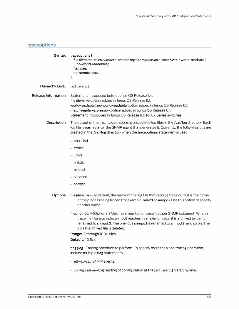
traceoptions
Syntax traceoptions {file filename <files number> <match regular-expression> <size size> <world-readable |no-world-readable>;
flag flag;no-remote-trace;
}
Hierarchy Level [edit snmp]
Release Information Statement introduced before Junos OS Release 7.4.
file filename option added in Junos OS Release 8.1.
world-readable | no-world-readable option added in Junos OS Release 8.1.
match regular-expression option added in Junos OS Release 8.1.
Statement introduced in Junos OS Release 9.0 for EX Series switches.
Description The output of the tracing operations is placed into log files in the /var/log directory. Each
log file is named after the SNMP agent that generates it. Currently, the following logs are
created in the /var/log directory when the traceoptions statement is used:
• chassisd
• craftd
• ilmid
• mib2d
• rmopd
• serviced
• snmpd
Options file filename—By default, the name of the log file that records trace output is the name
of the process being traced (for example,mib2dor snmpd). Use this option to specify
another name.
files number—(Optional) Maximum number of trace files per SNMP subagent. When a
trace file (for example, snmpd) reaches its maximum size, it is archived by being
renamed to snmpd.0. The previous snmpd.1 is renamed to snmpd.2, and so on. The
oldest archived file is deleted.
Range: 2 through 1000 files
Default: 10 files
flag flag—Tracing operation to perform. To specify more than one tracing operation,
include multiple flag statements:
• all—Log all SNMP events.
• configuration—Log reading of configuration at the [edit snmp] hierarchy level.
109Copyright © 2010, Juniper Networks, Inc.
Chapter 6: Summary of SNMP Configuration Statements
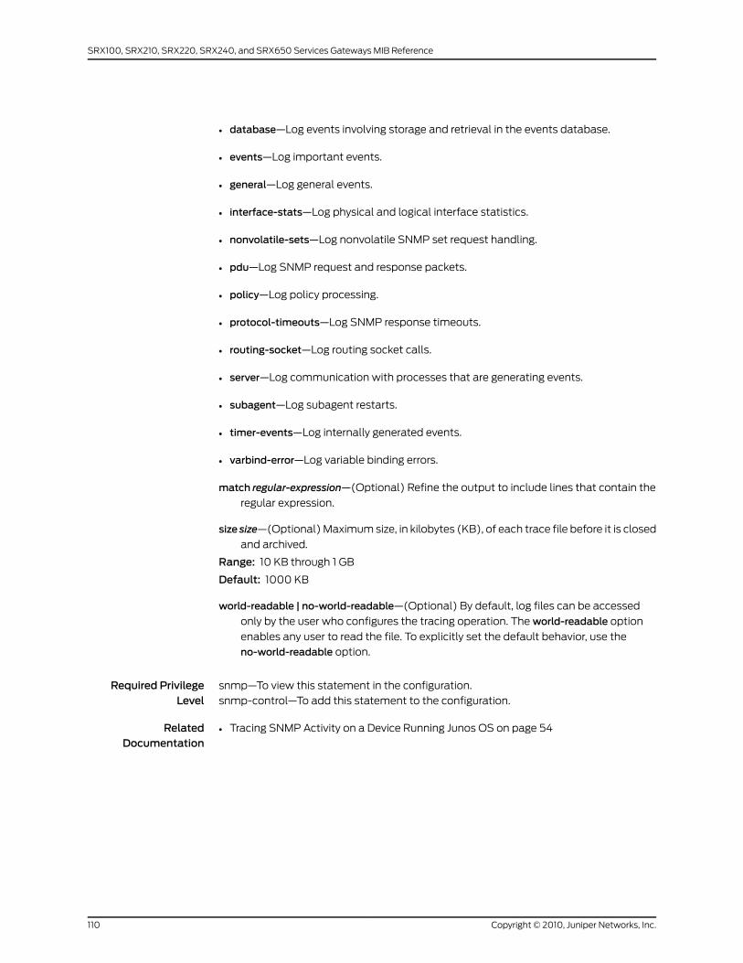
• database—Log events involving storage and retrieval in the events database.
• events—Log important events.
• general—Log general events.
• interface-stats—Log physical and logical interface statistics.
• nonvolatile-sets—Log nonvolatile SNMP set request handling.
• pdu—Log SNMP request and response packets.
• policy—Log policy processing.
• protocol-timeouts—Log SNMP response timeouts.
• routing-socket—Log routing socket calls.
• server—Log communication with processes that are generating events.
• subagent—Log subagent restarts.
• timer-events—Log internally generated events.
• varbind-error—Log variable binding errors.
match regular-expression—(Optional) Refine the output to include lines that contain the
regular expression.
size size—(Optional) Maximum size, in kilobytes (KB), of each trace file before it is closed
and archived.
Range: 10 KB through 1 GB
Default: 1000 KB
world-readable | no-world-readable—(Optional) By default, log files can be accessed
only by the user who configures the tracing operation. The world-readable option
enables any user to read the file. To explicitly set the default behavior, use the
no-world-readable option.
Required PrivilegeLevel
snmp—To view this statement in the configuration.
snmp-control—To add this statement to the configuration.
RelatedDocumentation
• Tracing SNMP Activity on a Device Running Junos OS on page 54
Copyright © 2010, Juniper Networks, Inc.110
SRX100, SRX210, SRX220, SRX240, and SRX650 Services Gateways MIB Reference
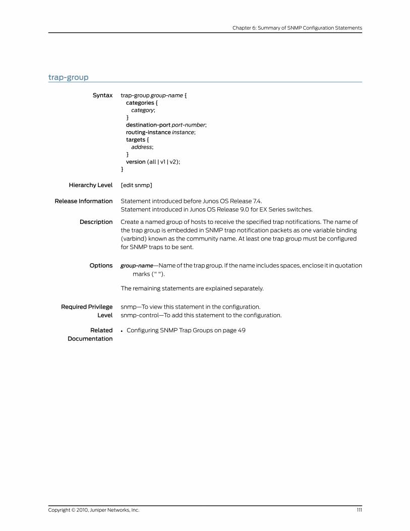
trap-group
Syntax trap-group group-name {categories {category;
}destination-port port-number;routing-instance instance;targets {address;
}version (all | v1 | v2);
}
Hierarchy Level [edit snmp]
Release Information Statement introduced before Junos OS Release 7.4.
Statement introduced in Junos OS Release 9.0 for EX Series switches.
Description Create a named group of hosts to receive the specified trap notifications. The name of
the trap group is embedded in SNMP trap notification packets as one variable binding
(varbind) known as the community name. At least one trap group must be configured
for SNMP traps to be sent.
Options group-name—Name of the trap group. If the name includes spaces, enclose it in quotation
marks (" ").
The remaining statements are explained separately.
Required PrivilegeLevel
snmp—To view this statement in the configuration.
snmp-control—To add this statement to the configuration.
RelatedDocumentation
• Configuring SNMP Trap Groups on page 49
111Copyright © 2010, Juniper Networks, Inc.
Chapter 6: Summary of SNMP Configuration Statements

trap-options
Syntax trap-options {agent-address outgoing-interface;source-address address;
}
Hierarchy Level [edit snmp]
Release Information Statement introduced before Junos OS Release 7.4.
Statement introduced in Junos OS Release 9.0 for EX Series switches.
Description Using SNMP trap options, you can set the source address of every SNMP trap packet
sent by the router to a single address, regardless of the outgoing interface. In addition,
you can set the agent address of each SNMPv1 trap. For more information about the
contents of SNMPv1 traps, see RFC 1157.
The remaining statements are explained separately.
Default Disabled
Required PrivilegeLevel
snmp—To view this statement in the configuration.
snmp-control—To add this statement to the configuration.
RelatedDocumentation
• Configuring SNMP Trap Options on page 46
version
Syntax version (all | v1 | v2);
Hierarchy Level [edit snmp trap-group group-name]
Release Information Statement introduced before Junos OS Release 7.4.
Statement introduced in Junos OS Release 9.0 for EX Series switches.
Description Specify the version number of SNMP traps.
Options all—Send an SNMPv1 and SNMPv2 trap for every trap condition.
v1—Send SNMPv1 traps only.
v2—Send SNMPv2 traps only.
Default: all
Required PrivilegeLevel
snmp—To view this statement in the configuration.
snmp-control—To add this statement to the configuration.
RelatedDocumentation
• Configuring SNMP Trap Groups on page 49
Copyright © 2010, Juniper Networks, Inc.112
SRX100, SRX210, SRX220, SRX240, and SRX650 Services Gateways MIB Reference
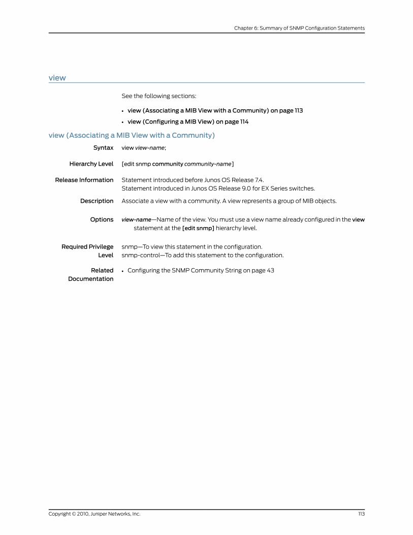
view
See the following sections:
• view (Associating aMIB Viewwith a Community) on page 113
• view (Configuring aMIB View) on page 114
view (Associating aMIB Viewwith a Community)
Syntax view view-name;
Hierarchy Level [edit snmp community community-name]
Release Information Statement introduced before Junos OS Release 7.4.
Statement introduced in Junos OS Release 9.0 for EX Series switches.
Description Associate a view with a community. A view represents a group of MIB objects.
Options view-name—Name of the view. You must use a view name already configured in the view
statement at the [edit snmp] hierarchy level.
Required PrivilegeLevel
snmp—To view this statement in the configuration.
snmp-control—To add this statement to the configuration.
RelatedDocumentation
• Configuring the SNMP Community String on page 43
113Copyright © 2010, Juniper Networks, Inc.
Chapter 6: Summary of SNMP Configuration Statements

view (Configuring aMIB View)
Syntax view view-name {oid object-identifier (include | exclude);
}
Hierarchy Level [edit snmp]
Release Information Statement introduced before Junos OS Release 7.4.
Statement introduced in Junos OS Release 9.0 for EX Series switches.
Description Define a MIB view. A MIB view identifies a group of MIB objects. Each MIB object in a view
has a common OID prefix. Each object identifier represents a subtree of the MIB object
hierarchy. The view statement uses a view to specify a group of MIB objects on which to
define access. To enable a view, you must associate the view with a community by
including the view statement at the [edit snmp community community-name] hierarchy
level.
NOTE: To remove an OID completely, use the delete view all oid oid-number
command but omit the include parameter.
Options view-name—Name of the view
The remaining statement is explained separately.
Required PrivilegeLevel
snmp—To view this statement in the configuration.
snmp-control—To add this statement to the configuration.
RelatedDocumentation
• Configuring MIB Views on page 53
• Associating MIB Views with an SNMP User Group
• community on page 98
Copyright © 2010, Juniper Networks, Inc.114
SRX100, SRX210, SRX220, SRX240, and SRX650 Services Gateways MIB Reference

CHAPTER 7
SNMP Remote Operations
This chapter contains the following topics:
• SNMP Remote Operations Overview on page 115
• Using the Ping MIB for Remote Monitoring Devices Running Junos OS on page 118
• Starting a Ping Test on page 118
• Monitoring a Running Ping Test on page 119
• Gathering Ping Test Results on page 122
• Stopping a Ping Test on page 124
• Interpreting Ping Variables on page 124
• Using the Traceroute MIB for Remote Monitoring Devices Running Junos OS on page 125
SNMPRemote Operations Overview
A SNMP remote operation is any process on the router that can be controlled remotely
using SNMP. Junos OS currently provides support for two SNMP remote operations: the
Ping MIB and Traceroute MIB, defined in RFC 2925. Using these MIBs, an SNMP client in
the network management system (NMS) can:
• Start a series of operations on a router
• Receive notification when the operations are complete
• Gather the results of each operation
Junos OS also provides extended functionality to these MIBs in the Juniper Networks
enterprise-specific extensions jnxPingMIB and jnxTraceRouteMIB. For more information
about jnxPingMIBand jnxTraceRouteMIB, see the “PING MIB” on page 339 and “Traceroute
MIB” on page 393 topics in the Junos SNMPMIBs and Traps Reference.
This topic covers the following sections:
• SNMP Remote Operation Requirements on page 116
• Setting SNMP Views on page 116
• Setting Trap Notification for Remote Operations on page 116
• Using Variable-Length String Indexes on page 117
• Enabling Logging on page 117
115Copyright © 2010, Juniper Networks, Inc.
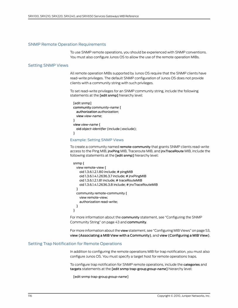
SNMPRemote Operation Requirements
To use SNMP remote operations, you should be experienced with SNMP conventions.
You must also configure Junos OS to allow the use of the remote operation MIBs.
Setting SNMPViews
All remote operation MIBs supported by Junos OS require that the SNMP clients have
read-write privileges. The default SNMP configuration of Junos OS does not provide
clients with a community string with such privileges.
To set read-write privileges for an SNMP community string, include the followingstatements at the [edit snmp] hierarchy level:
[edit snmp]community community-name {authorization authorization;view view-name;
}view view-name {oid object-identifier (include | exclude);
}
Example: Setting SNMPViews
To create a community named remote-community that grants SNMP clients read-writeaccess to the Ping MIB, jnxPing MIB, Traceroute MIB, and jnxTraceRoute MIB, include thefollowing statements at the [edit snmp] hierarchy level:
snmp {view remote-view {oid 1.3.6.1.2.1.80 include; # pingMIBoid 1.3.6.1.4.1.2636.3.7 include; # jnxPingMIBoid 1.3.6.1.2.1.81 include; # traceRouteMIBoid 1.3.6.1.4.1.2636.3.8 include; # jnxTraceRouteMIB
}community remote-community {view remote-view;authorization read-write;
}}
For more information about the community statement, see “Configuring the SNMP
Community String” on page 43 and community.
For more information about the view statement, see “Configuring MIB Views” on page 53,
view (Associating aMIBViewwith a Community), and view (Configuring aMIBView).
Setting Trap Notification for Remote Operations
In addition to configuring the remote operations MIB for trap notification, you must also
configure Junos OS. You must specify a target host for remote operations traps.
To configure trap notification for SNMP remote operations, include the categories andtargets statements at the [edit snmp trap-group group-name] hierarchy level:
[edit snmp trap-group group-name]
Copyright © 2010, Juniper Networks, Inc.116
SRX100, SRX210, SRX220, SRX240, and SRX650 Services Gateways MIB Reference
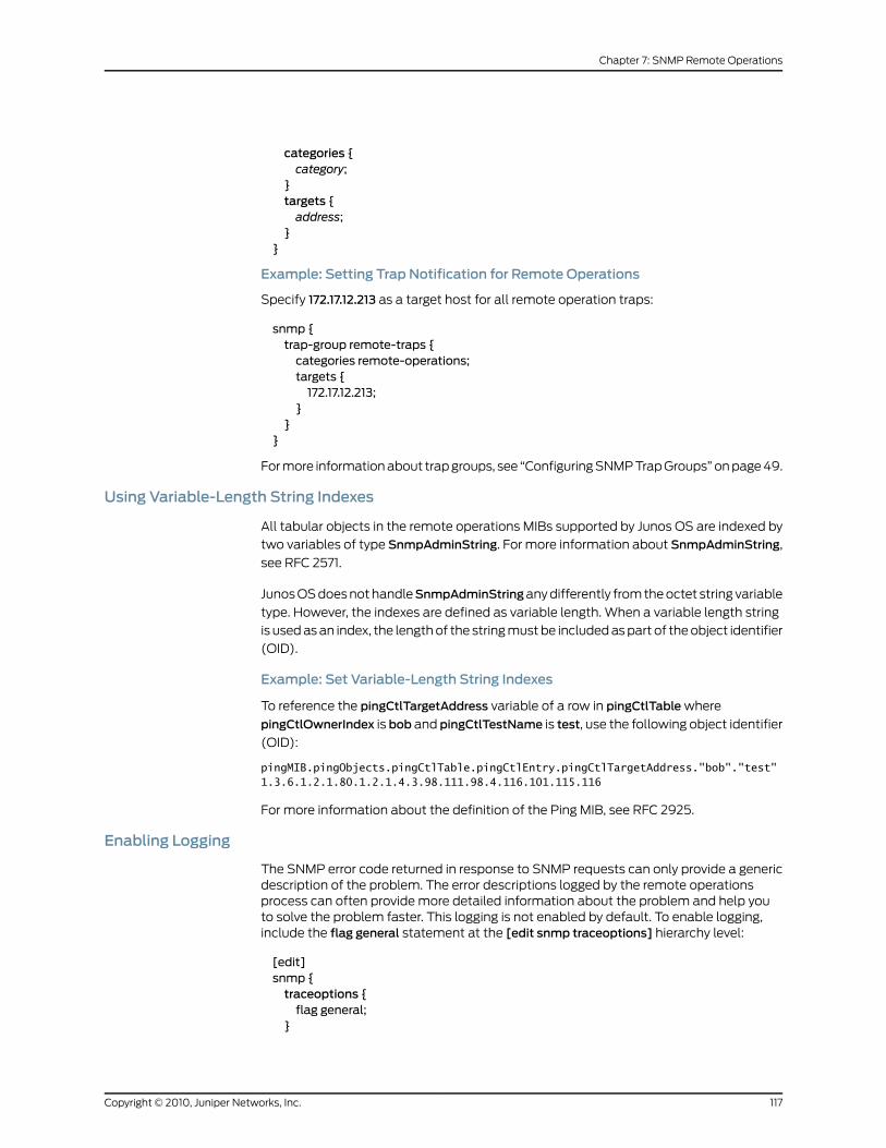
categories {category;
}targets {address;
}}
Example: Setting Trap Notification for Remote Operations
Specify 172.17.12.213 as a target host for all remote operation traps:
snmp {trap-group remote-traps {categories remote-operations;targets {172.17.12.213;
}}
}
For more information about trap groups, see “Configuring SNMP Trap Groups” on page 49.
Using Variable-Length String Indexes
All tabular objects in the remote operations MIBs supported by Junos OS are indexed by
two variables of type SnmpAdminString. For more information about SnmpAdminString,
see RFC 2571.
Junos OS does not handleSnmpAdminStringany differently from the octet string variable
type. However, the indexes are defined as variable length. When a variable length string
is used as an index, the length of the string must be included as part of the object identifier
(OID).
Example: Set Variable-Length String Indexes
To reference the pingCtlTargetAddress variable of a row in pingCtlTable where
pingCtlOwnerIndex is bob and pingCtlTestName is test, use the following object identifier
(OID):
pingMIB.pingObjects.pingCtlTable.pingCtlEntry.pingCtlTargetAddress."bob"."test" 1.3.6.1.2.1.80.1.2.1.4.3.98.111.98.4.116.101.115.116
For more information about the definition of the Ping MIB, see RFC 2925.
Enabling Logging
The SNMP error code returned in response to SNMP requests can only provide a genericdescription of the problem. The error descriptions logged by the remote operationsprocess can often provide more detailed information about the problem and help youto solve the problem faster. This logging is not enabled by default. To enable logging,include the flag general statement at the [edit snmp traceoptions] hierarchy level:
[edit]snmp {traceoptions {flag general;
}
117Copyright © 2010, Juniper Networks, Inc.
Chapter 7: SNMP Remote Operations
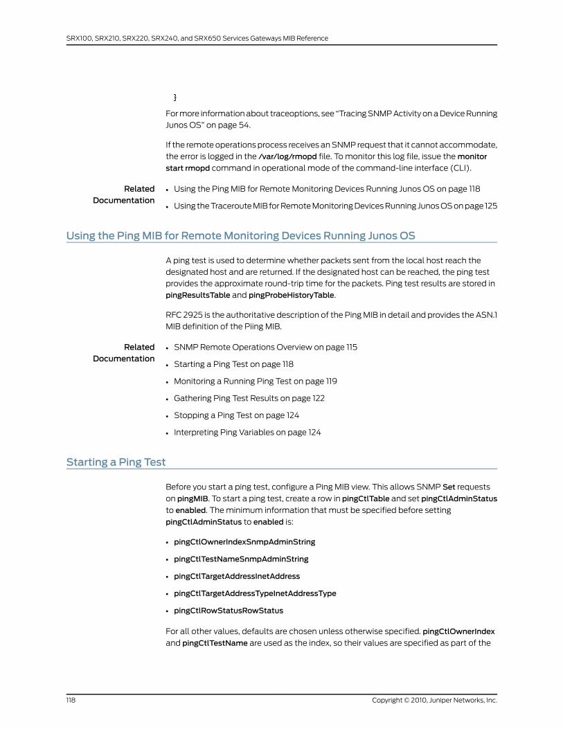
}
For more information about traceoptions, see “Tracing SNMP Activity on a Device Running
Junos OS” on page 54.
If the remote operations process receives an SNMP request that it cannot accommodate,
the error is logged in the /var/log/rmopd file. To monitor this log file, issue the monitor
start rmopd command in operational mode of the command-line interface (CLI).
RelatedDocumentation
Using the Ping MIB for Remote Monitoring Devices Running Junos OS on page 118•
• Using the Traceroute MIB for Remote Monitoring Devices Running Junos OS on page 125
Using the PingMIB for RemoteMonitoring Devices Running Junos OS
A ping test is used to determine whether packets sent from the local host reach the
designated host and are returned. If the designated host can be reached, the ping test
provides the approximate round-trip time for the packets. Ping test results are stored in
pingResultsTable and pingProbeHistoryTable.
RFC 2925 is the authoritative description of the Ping MIB in detail and provides the ASN.1
MIB definition of the Piing MIB.
RelatedDocumentation
SNMP Remote Operations Overview on page 115•
• Starting a Ping Test on page 118
• Monitoring a Running Ping Test on page 119
• Gathering Ping Test Results on page 122
• Stopping a Ping Test on page 124
• Interpreting Ping Variables on page 124
Starting a Ping Test
Before you start a ping test, configure a Ping MIB view. This allows SNMP Set requests
on pingMIB. To start a ping test, create a row in pingCtlTable and set pingCtlAdminStatus
to enabled. The minimum information that must be specified before setting
pingCtlAdminStatus to enabled is:
• pingCtlOwnerIndexSnmpAdminString
• pingCtlTestNameSnmpAdminString
• pingCtlTargetAddressInetAddress
• pingCtlTargetAddressTypeInetAddressType
• pingCtlRowStatusRowStatus
For all other values, defaults are chosen unless otherwise specified. pingCtlOwnerIndex
and pingCtlTestName are used as the index, so their values are specified as part of the
Copyright © 2010, Juniper Networks, Inc.118
SRX100, SRX210, SRX220, SRX240, and SRX650 Services Gateways MIB Reference
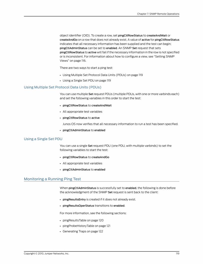
object identifier (OID). To create a row, set pingCtlRowStatus to createAndWait or
createAndGo on a row that does not already exist. A value of active for pingCtlRowStatus
indicates that all necessary information has been supplied and the test can begin;
pingCtlAdminStatus can be set to enabled. An SNMP Set request that sets
pingCtlRowStatus to activewill fail if the necessary information in the row is not specified
or is inconsistent. For information about how to configure a view, see “Setting SNMP
Views” on page 116.
There are two ways to start a ping test:
• Using Multiple Set Protocol Data Units (PDUs) on page 119
• Using a Single Set PDU on page 119
UsingMultiple Set Protocol Data Units (PDUs)
You can use multipleSet request PDUs (multiple PDUs, with one or more varbinds each)
and set the following variables in this order to start the test:
• pingCtlRowStatus to createAndWait
• All appropriate test variables
• pingCtlRowStatus to active
Junos OS now verifies that all necessary information to run a test has been specified.
• pingCtlAdminStatus to enabled
Using a Single Set PDU
You can use a single Set request PDU (one PDU, with multiple varbinds) to set the
following variables to start the test:
• pingCtlRowStatus to createAndGo
• All appropriate test variables
• pingCtlAdminStatus to enabled
Monitoring a Running Ping Test
When pingCtlAdminStatus is successfully set to enabled, the following is done before
the acknowledgment of the SNMP Set request is sent back to the client:
• pingResultsEntry is created if it does not already exist.
• pingResultsOperStatus transitions to enabled.
For more information, see the following sections:
• pingResultsTable on page 120
• pingProbeHistoryTable on page 121
• Generating Traps on page 122
119Copyright © 2010, Juniper Networks, Inc.
Chapter 7: SNMP Remote Operations

pingResultsTable
While the test is running, pingResultsEntry keeps track of the status of the test. The value
of pingResultsOperStatus is enabled while the test is running and disabled when it has
stopped.
The value of pingCtlAdminStatus remains enabled until you set it to disabled. Thus, to
get the status of the test, you must examine pingResultsOperStatus.
The pingCtlFrequency variable can be used to schedule many tests for one pingCtlEntry.
After a test ends normally (you did not stop the test) and the pingCtlFrequency number
of seconds has elapsed, the test is started again just as if you had setpingCtlAdminStatus
to enabled. If you intervene at any time between repeated tests (you set
pingCtlAdminStatus to disabled or pingCtlRowStatus to notInService), the repeat feature
is disabled until another test is started and ends normally. A value of 0 for
pingCtlFrequency indicates this repeat feature is not active.
pingResultsIpTgtAddr and pingResultsIpTgtAddrType are set to the value of the resolved
destination address when the value of pingCtlTargetAddressType is dns. When a test
starts successfully and pingResultsOperStatus transitions to enabled:
• pingResultsIpTgtAddr is set to null-string.
• pingResultsIpTgtAddrType is set to unknown.
pingResultsIpTgtAddr and pingResultsIpTgtAddrType are not set until
pingCtlTargetAddress can be resolved to a numeric address. To retrieve these values,
pollpingResultsIpTgtAddrType for any value other thanunknownafter successfully setting
pingCtlAdminStatus to enabled.
At the start of a test, pingResultsSentProbes is initialized to 1 and the first probe is sent.
pingResultsSentProbes increases by 1 each time a probe is sent.
As the test runs, every pingCtlTimeOut seconds, the following occur:
• pingProbeHistoryStatus for the corresponding pingProbeHistoryEntry in
pingProbeHistoryTable is set to requestTimedOut.
• A pingProbeFailed trap is generated, if necessary.
• An attempt is made to send the next probe.
NOTE: Nomore than one outstanding probe exists for each test.
For every probe, you can receive one of the following results:
• The target host acknowledges the probe with a response.
• The probe times out; there is no response from the target host acknowledging the
probe.
• The probe could not be sent.
Copyright © 2010, Juniper Networks, Inc.120
SRX100, SRX210, SRX220, SRX240, and SRX650 Services Gateways MIB Reference
Each probe result is recorded in pingProbeHistoryTable. For more information about
pingProbeHistoryTable, see “pingProbeHistoryTable” on page 121.
When a response is received from the target host acknowledging the current probe:
• pingResultsProbeResponses increases by 1.
• The following variables are updated:
• pingResultsMinRtt—Minimum round-trip time
• pingResultsMaxRtt—Maximum round-trip time
• pingResultsAverageRtt—Average round-trip time
• pingResultsRttSumOfSquares—Sum of squares of round-trip times
• pingResultsLastGoodProbe—Timestamp of the last response
NOTE: Only probes that result in a response from the target hostcontribute to the calculation of the round-trip time (RTT) variables.
When a response to the last probe is received or the last probe has timed out, the test is
complete.
pingProbeHistoryTable
An entry in pingProbeHistoryTable (pingProbeHistoryEntry) represents a probe result and
is indexed by three variables:
• The first two variables, pingCtlOwnerIndex and pingCtlTestName, are the same ones
used for pingCtlTable, which identifies the test.
• The third variable, pingProbeHistoryIndex, is a counter to uniquely identify each probe
result.
The maximum number ofpingProbeHistoryTable entries created for a given test is limited
by pingCtlMaxRows. If pingCtlMaxRows is set to 0, no pingProbeHistoryTable entries are
created for that test.
Each time a probe result is determined, a pingProbeHistoryEntry is created and added to
pingProbeHistoryTable. pingProbeHistoryIndex of the new pingProbeHistoryEntry is 1
greater than the lastpingProbeHistoryEntry added topingProbeHistoryTable for that test.
pingProbeHistoryIndex is set to 1 if this is the first entry in the table. The same test can be
run multiple times, so this index keeps growing.
IfpingProbeHistoryIndexof the lastpingProbeHistoryEntryadded is 0xFFFFFFFF, the next
pingProbeHistoryEntry added has pingProbeHistoryIndex set to 1.
The following is recorded for each probe result:
121Copyright © 2010, Juniper Networks, Inc.
Chapter 7: SNMP Remote Operations
• pingProbeHistoryResponse—Time to live (TTL)
• pingProbeHistoryStatus—What happened and why
• pingProbeHistoryLastRC—Return code (RC) value of ICMP packet
• pingProbeHistoryTime—Timestamp when probe result was determined
When a probe cannot be sent,pingProbeHistoryResponse is set to 0. When a probe times
out, pingProbeHistoryResponse is set to the difference between the time when the probe
was discovered to be timed out and the time when the probe was sent.
Generating Traps
For any trap to be generated, the appropriate bit of pingCtlTrapGeneration must be set.
You must also configure a trap group to receive remote operations. A trap is generated
under the following conditions:
• A pingProbeFailed trap is generated every time pingCtlTrapProbeFailureFilter number
of consecutive probes fail during the test.
• A pingTestFailed trap is generated when the test completes and at least
pingCtlTrapTestFailureFilter number of probes fail.
• A pingTestCompleted trap is generated when the test completes and fewer than
pingCtlTrapTestFailureFilter probes fail.
NOTE: A probe is considered a failure when pingProbeHistoryStatus of the
probe result is anything besides responseReceived.
For information about how to configure a trap group to receive remote operations, see
“Configuring SNMP Trap Groups” on page 49 and “Example: Setting Trap Notification
for Remote Operations” on page 117.
Gathering Ping Test Results
You can either pollpingResultsOperStatus to find out when the test is complete or request
that a trap be sent when the test is complete. For more information about
pingResultsOperStatus, see “pingResultsTable” on page 120. For more information about
Ping MIB traps, see “Generating Traps” on page 122.
The statistics calculated and then stored in pingResultsTable include:
• pingResultsMinRtt—Minimum round-trip time
• pingResultsMaxRtt—Maximum round-trip time
• pingResultsAverageRtt—Average round-trip time
• pingResultsProbeResponses—Number of responses received
• pingResultsSentProbes—Number of attempts to send probes
Copyright © 2010, Juniper Networks, Inc.122
SRX100, SRX210, SRX220, SRX240, and SRX650 Services Gateways MIB Reference
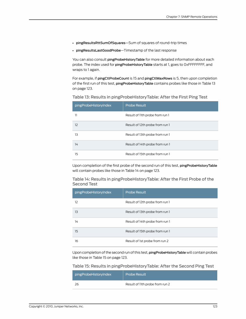
• pingResultsRttSumOfSquares—Sum of squares of round-trip times
• pingResultsLastGoodProbe—Timestamp of the last response
You can also consult pingProbeHistoryTable for more detailed information about each
probe. The index used for pingProbeHistoryTable starts at 1, goes to 0xFFFFFFFF, and
wraps to 1 again.
For example, if pingCtlProbeCount is 15 and pingCtlMaxRows is 5, then upon completion
of the first run of this test, pingProbeHistoryTable contains probes like those in Table 13
on page 123.
Table 13: Results in pingProbeHistoryTable: After the First Ping Test
Probe ResultpingProbeHistoryIndex
Result of 11th probe from run 111
Result of 12th probe from run 112
Result of 13th probe from run 113
Result of 14th probe from run 114
Result of 15th probe from run 115
Upon completion of the first probe of the second run of this test, pingProbeHistoryTable
will contain probes like those in Table 14 on page 123.
Table 14: Results in pingProbeHistoryTable: After the First Probe of theSecond Test
Probe ResultpingProbeHistoryIndex
Result of 12th probe from run 112
Result of 13th probe from run 113
Result of 14th probe from run 114
Result of 15th probe from run 115
Result of 1st probe from run 216
Upon completion of the second run of this test,pingProbeHistoryTablewill contain probes
like those in Table 15 on page 123.
Table 15: Results in pingProbeHistoryTable: After the Second Ping Test
Probe ResultpingProbeHistoryIndex
Result of 11th probe from run 226
123Copyright © 2010, Juniper Networks, Inc.
Chapter 7: SNMP Remote Operations
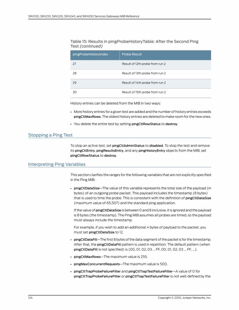
Table 15: Results in pingProbeHistoryTable: After the Second PingTest (continued)
Probe ResultpingProbeHistoryIndex
Result of 12th probe from run 227
Result of 13th probe from run 228
Result of 14th probe from run 229
Result of 15th probe from run 230
History entries can be deleted from the MIB in two ways:
• More history entries for a given test are added and the number of history entries exceeds
pingCtlMaxRows. The oldest history entries are deleted to make room for the new ones.
• You delete the entire test by setting pingCtlRowStatus to destroy.
Stopping a Ping Test
To stop an active test, set pingCtlAdminStatus to disabled. To stop the test and remove
its pingCtlEntry, pingResultsEntry, and any pingHistoryEntry objects from the MIB, set
pingCtlRowStatus to destroy.
Interpreting Ping Variables
This section clarifies the ranges for the following variables that are not explicitly specified
in the Ping MIB:
• pingCtlDataSize—The value of this variable represents the total size of the payload (in
bytes) of an outgoing probe packet. This payload includes the timestamp (8 bytes)
that is used to time the probe. This is consistent with the definition of pingCtlDataSize
(maximum value of 65,507) and the standard ping application.
If the value ofpingCtlDataSize is between 0 and 8 inclusive, it is ignored and the payload
is 8 bytes (the timestamp). The Ping MIB assumes all probes are timed, so the payload
must always include the timestamp.
For example, if you wish to add an additional 4 bytes of payload to the packet, you
must set pingCtlDataSize to 12.
• pingCtlDataFill—The first 8 bytes of the data segment of the packet is for the timestamp.
After that, the pingCtlDataFill pattern is used in repetition. The default pattern (when
pingCtlDataFill is not specified) is (00, 01, 02, 03 ... FF, 00, 01, 02, 03 ... FF, ...).
• pingCtlMaxRows—The maximum value is 255.
• pingMaxConcurrentRequests—The maximum value is 500.
• pingCtlTrapProbeFailureFilter and pingCtlTrapTestFailureFilter—A value of 0 for
pingCtlTrapProbeFailureFilter or pingCtlTrapTestFailureFilter is not well defined by the
Copyright © 2010, Juniper Networks, Inc.124
SRX100, SRX210, SRX220, SRX240, and SRX650 Services Gateways MIB Reference

Ping MIB. If pingCtlTrapProbeFailureFilter is 0, pingProbeFailed traps will not be
generated for the test under any circumstances. If pingCtlTrapTestFailureFilter is 0,
pingTestFailed traps will not be generated for the test under any circumstances.
Using the TracerouteMIB for RemoteMonitoring Devices Running Junos OS
A traceroute test approximates the path packets take from the local host to the remote
host.
RFC 2925 is the authoritative description of the Traceroute MIB in detail and provides
the ASN.1 MIB definition of the Traceroute MIB.
RelatedDocumentation
• SNMP Remote Operations Overview on page 115
• Starting a Traceroute Test
• Monitoring a Running Traceroute Test
• Monitoring Traceroute Test Completion
• Gathering Traceroute Test Results
• Stopping a Traceroute Test
• Interpreting Traceroute Variables
125Copyright © 2010, Juniper Networks, Inc.
Chapter 7: SNMP Remote Operations

Copyright © 2010, Juniper Networks, Inc.126
SRX100, SRX210, SRX220, SRX240, and SRX650 Services Gateways MIB Reference
CHAPTER 8
SNMP Support for Routing Instances
This chapter contains the following topics:
• Understanding SNMP Support for Routing Instances on page 127
• Support Classes for MIB Objects on page 128
• Identifying a Routing Instance on page 129
• Enabling SNMP Access over Routing Instances on page 130
• Specifying a Routing Instance in an SNMPv1 or SNMPv2c Community on page 131
• Example: Configuring Interface Settings for a Routing Instance on page 132
• Configuring Access Lists for SNMP Access over Routing Instances on page 133
• Trap Support for Routing Instances on page 134
• MIB Support Details on page 134
Understanding SNMPSupport for Routing Instances
Junos OS enables SNMP managers for all routing instances to request and manage SNMP
data related to the corresponding routing instances and logical system networks.
In Junos OS:
• Clients from routing instances other than the default can access MIB objects and
perform SNMP operations only on the logical system networks to which they belong.
• Clients from the default routing instance can access information related to all routing
instances and logical system networks.
Before Junos OS Release 8.4, only the SNMP manager in the default routing instance
(inet.0) had access to the MIB objects
With the increase in virtual private network (VPN) service offerings, this feature is useful
particularly for service providers who need to obtain SNMP data for specific routing
instances (see Figure 2 on page 128). Service providers can use this information for their
own management needs or export the data for use by their customers.
127Copyright © 2010, Juniper Networks, Inc.
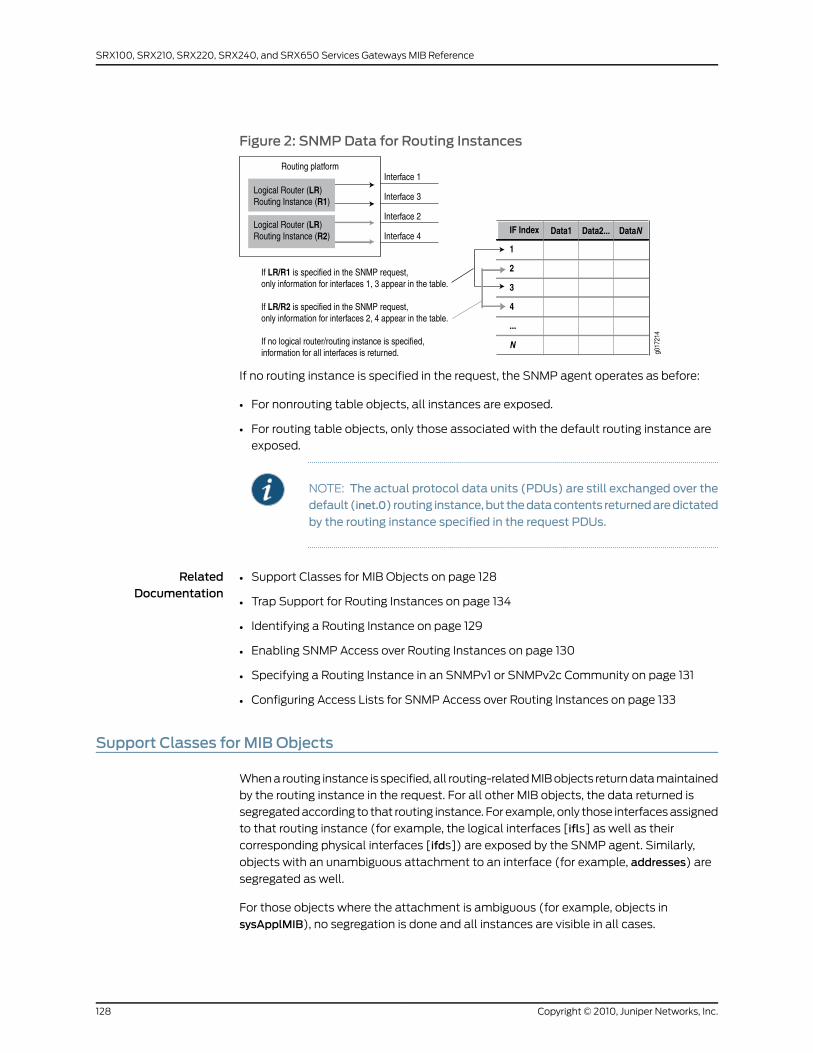
Figure 2: SNMPData for Routing Instances
If no routing instance is specified in the request, the SNMP agent operates as before:
• For nonrouting table objects, all instances are exposed.
• For routing table objects, only those associated with the default routing instance are
exposed.
NOTE: The actual protocol data units (PDUs) are still exchanged over thedefault (inet.0) routing instance,but thedatacontents returnedaredictated
by the routing instance specified in the request PDUs.
RelatedDocumentation
Support Classes for MIB Objects on page 128•
• Trap Support for Routing Instances on page 134
• Identifying a Routing Instance on page 129
• Enabling SNMP Access over Routing Instances on page 130
• Specifying a Routing Instance in an SNMPv1 or SNMPv2c Community on page 131
• Configuring Access Lists for SNMP Access over Routing Instances on page 133
Support Classes for MIB Objects
When a routing instance is specified, all routing-related MIB objects return data maintained
by the routing instance in the request. For all other MIB objects, the data returned is
segregated according to that routing instance. For example, only those interfaces assigned
to that routing instance (for example, the logical interfaces [ifls] as well as their
corresponding physical interfaces [ifds]) are exposed by the SNMP agent. Similarly,
objects with an unambiguous attachment to an interface (for example, addresses) are
segregated as well.
For those objects where the attachment is ambiguous (for example, objects in
sysApplMIB), no segregation is done and all instances are visible in all cases.
Copyright © 2010, Juniper Networks, Inc.128
SRX100, SRX210, SRX220, SRX240, and SRX650 Services Gateways MIB Reference
Another category of objects is visible only when no logical system is specified (only within
the default logical system) regardless of the routing instance within the default logical
system. Objects in this category are Chassis MIB objects, objects in the SNMP group,
RMON alarm, event and log groups, Ping MIB objects, configuration management objects,
and V3 objects.
In summary, to support routing instances, MIB objects fall into one of the following
categories:
• Class 1—Data is segregated according to the routing instance in the request. This is the
most granular of the segregation classes.
• Class 2—Data is segregated according to the logical system specified in the request.
The same data is returned for all routing instances that belong to a particular logical
system. Typically, this applies to routing table objects where it is difficult to extract
routing instance information or where routing instances do not apply.
• Class 3—Data is exposed only for the default logical system. The same set of data is
returned for all routing instances that belong to the default logical system. If you specify
another logical system (not the default), no data is returned. Typically this class applies
to objects implemented in subagents that do not monitor logical system changes and
register their objects using only the default context (for example, Chassis MIB objects).
• Class 4—Data is not segregated by routing instance. The same data is returned for all
routing instances. Typically, this applies to objects implemented in subagents that
monitor logical system changes and register or deregister all their objects for each
logical system change. Objects whose values cannot be segregated by routing instance
fall into this class.
See “MIB Support Details” on page 134 for a list of the objects associated with each class.
RelatedDocumentation
Understanding SNMP Support for Routing Instances on page 127•
• Trap Support for Routing Instances on page 134
Identifying a Routing Instance
With this feature, routing instances are identified by either the context field in v3 requests
or encoded in the community string in v1 or v2c requests.
When encoded in a community string, the routing instance name appears first and is
separated from the actual community string by the @ character.
To avoid conflicts with valid community strings that contain the @ character, the
community is parsed only if typical community string processing fails. For example, if a
routing instance named RI is configured, an SNMP request with RI@public is processed
within the context of the RI routing instance. Access control (views, source address
restrictions, access privileges, and so on) is applied according to the actual community
string (the set of data after the @ character—in this case public). However, if the
community string RI@public is configured, the protocol data unit (PDU) is processed
according to that community and the embedded routing instance name is ignored.
129Copyright © 2010, Juniper Networks, Inc.
Chapter 8: SNMP Support for Routing Instances

Logical systems perform a subset of the actions of a physical router and have their own
unique routing tables, interfaces, policies, and routing instances. When a routing instance
is defined within a logical system, the logical system name must be encoded along with
the routing instance using a slash ( / ) to separate the two. For example, if the routing
instance RI is configured within the logical system LS, that routing instance must be
encoded within a community string asLS/RI@public. When a routing instance is configured
outside a logical system (within the default logical system), no logical system name (or
/ character) is needed.
Also, when a logical system is created, a default routing instance (named default) is
always created within the logical system. This name should be used when querying data
for that routing instance (for example, LS/default@public). For v3 requests, the name
logical system/routing instance should be identified directly in the context field.
NOTE: To identify a virtual LAN (VLAN) spanning-tree instance (VSTP onMX Series Ethernet Services Routers), specify the routing instance namefollowed by a double colon (::) and the VLAN ID. For example, to identify
VSTP instance for VLAN 10 in the global default routing instance, includedefault::10@public in the context (SNMPv3) or community (SNMPv1 or v2)
string.
RelatedDocumentation
Understanding SNMP Support for Routing Instances on page 127•
• Enabling SNMP Access over Routing Instances on page 130
• Specifying a Routing Instance in an SNMPv1 or SNMPv2c Community on page 131
Enabling SNMPAccess over Routing Instances
To enable SNMP managers in routing instances other than the default routing instanceto access SNMP information, include the routing-instance-access statement at the [editsnmp] hierarchy level:
[edit snmp]routing-instance-access;
If this statement is not included in the SNMP configuration, SNMP managers from routing
instances other than the default routing instance cannot access SNMP information.
RelatedDocumentation
Understanding SNMP Support for Routing Instances on page 127•
• Identifying a Routing Instance on page 129
• Specifying a Routing Instance in an SNMPv1 or SNMPv2c Community on page 131
• Configuring Access Lists for SNMP Access over Routing Instances on page 133
Copyright © 2010, Juniper Networks, Inc.130
SRX100, SRX210, SRX220, SRX240, and SRX650 Services Gateways MIB Reference
Specifying a Routing Instance in an SNMPv1 or SNMPv2c Community
You can specify the routing instance along with the client information when you add a
client to an SNMP community. To specify the routing instance to which a client belongs,
include the routing-instance statement followed by the routing instance name and client
information in the SNMP configuration.
The following example shows the configuration statement to add routing instance test-ri
to SNMP community community1.
NOTE: Routing instances specified at the [edit snmp community
community-name] hierarchy level are added to the default logical system in
the community.
[edit snmp]community community1 {clients {10.209.152.33/32;
}routing-instance test-ri {clients {10.19.19.1/32;
}}
}
If the routing instance is defined within a logical system, include the routing-instancestatement at the [edit snmp community community-name logical-systemlogical-system-name] hierarchy level, as in the following example:
[edit snmp]community community1 {clients {10.209.152.33/32;
}logical-system test-LS {routing-instance test-ri {clients {10.19.19.1/32;
}}
}}
RelatedDocumentation
Understanding SNMP Support for Routing Instances on page 127•
• Identifying a Routing Instance on page 129
• Enabling SNMP Access over Routing Instances on page 130
• Configuring Access Lists for SNMP Access over Routing Instances on page 133
• Example: Configuring Interface Settings for a Routing Instance on page 132
131Copyright © 2010, Juniper Networks, Inc.
Chapter 8: SNMP Support for Routing Instances
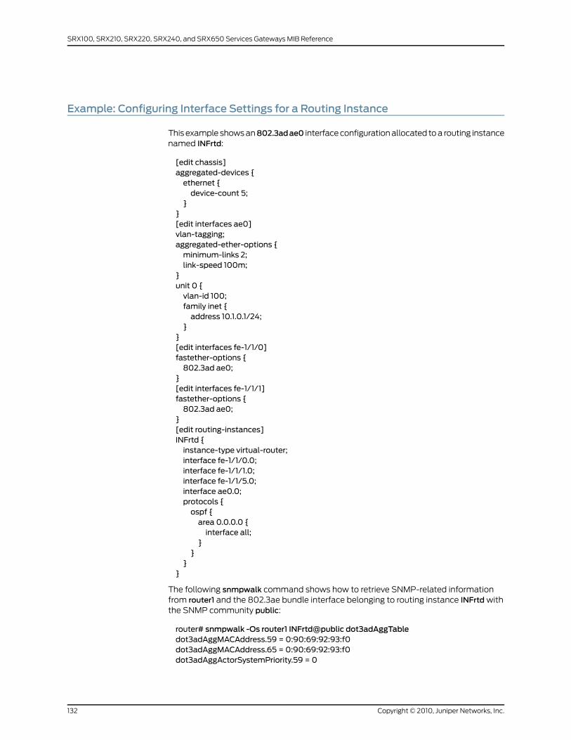
Example: Configuring Interface Settings for a Routing Instance
This example shows an802.3adae0 interface configuration allocated to a routing instancenamed INFrtd:
[edit chassis]aggregated-devices {ethernet {device-count 5;
}}[edit interfaces ae0]vlan-tagging;aggregated-ether-options {minimum-links 2;link-speed 100m;
}unit 0 {vlan-id 100;family inet {address 10.1.0.1/24;
}}[edit interfaces fe-1/1/0]fastether-options {802.3ad ae0;
}[edit interfaces fe-1/1/1]fastether-options {802.3ad ae0;
}[edit routing-instances]INFrtd {instance-type virtual-router;interface fe-1/1/0.0;interface fe-1/1/1.0;interface fe-1/1/5.0;interface ae0.0;protocols {ospf {area 0.0.0.0 {interface all;
}}
}}
The following snmpwalk command shows how to retrieve SNMP-related informationfrom router1 and the 802.3ae bundle interface belonging to routing instance INFrtd withthe SNMP community public:
router# snmpwalk -Os router1 INFrtd@public dot3adAggTabledot3adAggMACAddress.59 = 0:90:69:92:93:f0dot3adAggMACAddress.65 = 0:90:69:92:93:f0dot3adAggActorSystemPriority.59 = 0
Copyright © 2010, Juniper Networks, Inc.132
SRX100, SRX210, SRX220, SRX240, and SRX650 Services Gateways MIB Reference

dot3adAggActorSystemPriority.65 = 0dot3adAggActorSystemID.59 = 0:0:0:0:0:0dot3adAggActorSystemID.65 = 0:0:0:0:0:0dot3adAggAggregateOrIndividual.59 = true(1)dot3adAggAggregateOrIndividual.65 = true(1)dot3adAggActorAdminKey.59 = 0dot3adAggActorAdminKey.65 = 0dot3adAggActorOperKey.59 = 0dot3adAggActorOperKey.65 = 0dot3adAggPartnerSystemID.59 = 0:0:0:0:0:0dot3adAggPartnerSystemID.65 = 0:0:0:0:0:0dot3adAggPartnerSystemPriority.59 = 0dot3adAggPartnerSystemPriority.65 = 0dot3adAggPartnerOperKey.59 = 0dot3adAggPartnerOperKey.65 = 0dot3adAggCollectorMaxDelay.59 = 0dot3adAggCollectorMaxDelay.65 = 0
RelatedDocumentation
Understanding SNMP Support for Routing Instances on page 127•
• Specifying a Routing Instance in an SNMPv1 or SNMPv2c Community on page 131
Configuring Access Lists for SNMPAccess over Routing Instances
You can create and maintain access lists to manage access to SNMP information. Access
list configuration enables you to allow or deny SNMP access to clients of a specific routing
instance.
The following example shows how to create an access list:
[edit snmp]routing-instance-access {access-list {ri1 restrict;ls1/default;ls1/ri2;ls1*;
}}
The configuration given in the example:
• Restricts clients in ri1 from accessing SNMP information.
• Allows clients in ls1/default, ls1/ri2, and all other routing instances with names starting
with ls1 to access SNMP information.
You can use the wildcard character (*) to represent a string in the routing instance name.
NOTE: Youcannot restrict theSNMPmanagerof thedefault routing instancefrom accessing SNMP information.
133Copyright © 2010, Juniper Networks, Inc.
Chapter 8: SNMP Support for Routing Instances
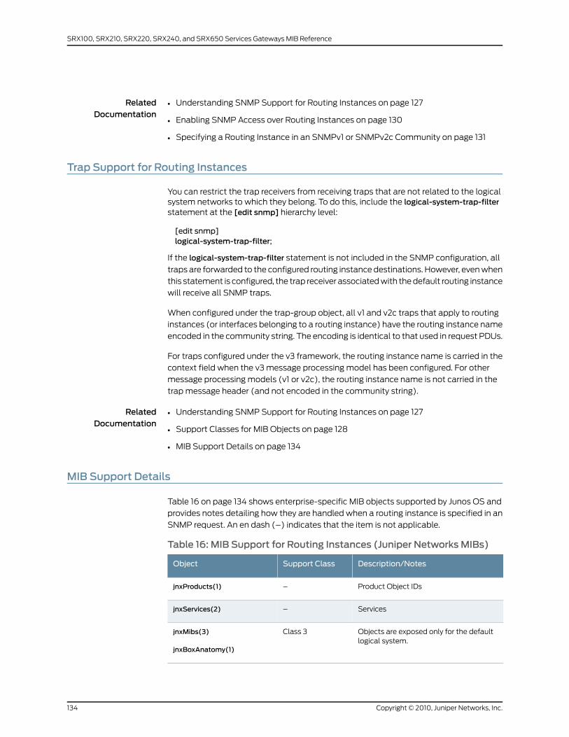
RelatedDocumentation
Understanding SNMP Support for Routing Instances on page 127•
• Enabling SNMP Access over Routing Instances on page 130
• Specifying a Routing Instance in an SNMPv1 or SNMPv2c Community on page 131
Trap Support for Routing Instances
You can restrict the trap receivers from receiving traps that are not related to the logicalsystem networks to which they belong. To do this, include the logical-system-trap-filterstatement at the [edit snmp] hierarchy level:
[edit snmp]logical-system-trap-filter;
If the logical-system-trap-filter statement is not included in the SNMP configuration, all
traps are forwarded to the configured routing instance destinations. However, even when
this statement is configured, the trap receiver associated with the default routing instance
will receive all SNMP traps.
When configured under the trap-group object, all v1 and v2c traps that apply to routing
instances (or interfaces belonging to a routing instance) have the routing instance name
encoded in the community string. The encoding is identical to that used in request PDUs.
For traps configured under the v3 framework, the routing instance name is carried in the
context field when the v3 message processing model has been configured. For other
message processing models (v1 or v2c), the routing instance name is not carried in the
trap message header (and not encoded in the community string).
RelatedDocumentation
Understanding SNMP Support for Routing Instances on page 127•
• Support Classes for MIB Objects on page 128
• MIB Support Details on page 134
MIB Support Details
Table 16 on page 134 shows enterprise-specific MIB objects supported by Junos OS and
provides notes detailing how they are handled when a routing instance is specified in an
SNMP request. An en dash (–) indicates that the item is not applicable.
Table 16: MIB Support for Routing Instances (Juniper Networks MIBs)
Description/NotesSupport ClassObject
Product Object IDs–jnxProducts(1)
Services–jnxServices(2)
Objects are exposed only for the defaultlogical system.
Class 3jnxMibs(3)
jnxBoxAnatomy(1)
Copyright © 2010, Juniper Networks, Inc.134
SRX100, SRX210, SRX220, SRX240, and SRX650 Services Gateways MIB Reference

Table 16: MIB Support for Routing Instances (Juniper NetworksMIBs) (continued)
Description/NotesSupport ClassObject
All instances within a logical system areexposed. Data will not be segregated downto the routing instance level.
Class 2mpls(2)
Only those logical interfaces (and theirparent physical interfaces) that belong toa specific routing instance are exposed.
Class 1ifJnx(3)
Objects are exposed only for the defaultlogical system.
Class 3jnxAlarms(4)
Data is not segregated by routing instance.All instances are exposed.
Class 4jnxFirewalls(5)
Only those logical interfaces (and theirparent physical interfaces) that belong toa specific routing instance are exposed.
Class 1jnxDCUs(6)
Objects are exposed only for the defaultlogical system.
Class 3jnxPingMIB(7)
Objects are exposed only for the defaultlogical system.
Class 3jnxTraceRouteMIB(8)
Only those logical interfaces (and theirparent physical interfaces) that belong toa specific routing instance are exposed.
Class 1jnxATM(10)
Data is not segregated by routing instance.All instances are exposed.
Class 4jnxIpv6(11)
jnxIpv4AddrTable(1). Only those logicalinterfaces (and their parent physicalinterfaces) that belong to a specific routinginstance are exposed.
Class 1jnxIpv4(12)
jnxRmonAlarmTable(1). Objects areexposed only for the default logicalsystem.
Class 3jnxRmon(13)
jnxLdpTrapVars(1). All instances within alogical system are exposed. Data will notbe segregated down to the routinginstance level.
Class 2jnxLdp(14)
135Copyright © 2010, Juniper Networks, Inc.
Chapter 8: SNMP Support for Routing Instances

Table 16: MIB Support for Routing Instances (Juniper NetworksMIBs) (continued)
Description/NotesSupport ClassObject
Objects are exposed only for the defaultlogical system.
Class 3jnxCos(15)
jnxCosIfqStatsTable(1)jnxCosFcTable(2)jnxCosFcIdTable(3)jnxCosQstatTable(4)
Only those logical interfaces (and theirparent physical interfaces) that belong toa specific routing instance are exposed.
Class 1jnxScu(16)
jnxScuStatsTable(1)
Only those logical interfaces (and theirparent physical interfaces) that belong toa specific routing instance are exposed.
Class 1jnxRpf(17)
jnxRpfStatsTable(1)
Objects are exposed only for the defaultlogical system.
Class 3jnxCfgMgmt(18)
Only those logical interfaces (and theirparent physical interfaces) that belong toa specific routing instance are exposed.
Class 1jnxPMon(19)
jnxPMonFlowTable(1)
jnxPMonErrorTable(2)
jnxPMonMemoryTable(3)
Only those logical interfaces (and theirparent physical interfaces) that belong toa specific routing instance are exposed.
Class 1jnxSonet(20)
jnxSonetAlarmTable(1)
Only those logical interfaces (and theirparent physical interfaces) that belong toa specific routing instance are exposed.
Class 1jnxAtmCos(21)
jnxCosAtmVcTable(1)
jnxCosAtmScTable(2)
jnxCosAtmVcQstatsTable(3)
jnxCosAtmTrunkTable(4)
––ipSecFlowMonitorMIB(22)
Only those logical interfaces (and theirparent physical interfaces) that belong toa specific routing instance are exposed.
Class 1jnxMac(23)
jnxMacStats(1)
Objects are exposed only for the defaultlogical system.
Class 3apsMIB(24)
Objects are exposed only for the defaultlogical system.
Class 3jnxChassisDefines(25)
Copyright © 2010, Juniper Networks, Inc.136
SRX100, SRX210, SRX220, SRX240, and SRX650 Services Gateways MIB Reference
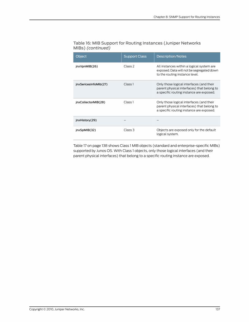
Table 16: MIB Support for Routing Instances (Juniper NetworksMIBs) (continued)
Description/NotesSupport ClassObject
All instances within a logical system areexposed. Data will not be segregated downto the routing instance level.
Class 2jnxVpnMIB(26)
Only those logical interfaces (and theirparent physical interfaces) that belong toa specific routing instance are exposed.
Class 1jnxSericesInfoMib(27)
Only those logical interfaces (and theirparent physical interfaces) that belong toa specific routing instance are exposed.
Class 1jnxCollectorMIB(28)
––jnxHistory(29)
Objects are exposed only for the defaultlogical system.
Class 3jnxSpMIB(32)
Table 17 on page 138 shows Class 1 MIB objects (standard and enterprise-specific MIBs)
supported by Junos OS. With Class 1 objects, only those logical interfaces (and their
parent physical interfaces) that belong to a specific routing instance are exposed.
137Copyright © 2010, Juniper Networks, Inc.
Chapter 8: SNMP Support for Routing Instances
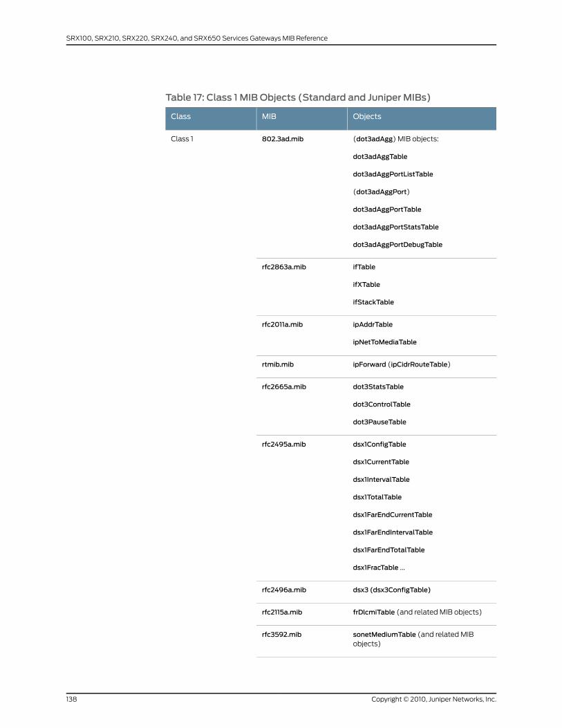
Table 17: Class 1 MIB Objects (Standard and Juniper MIBs)
ObjectsMIBClass
(dot3adAgg) MIB objects:
dot3adAggTable
dot3adAggPortListTable
(dot3adAggPort)
dot3adAggPortTable
dot3adAggPortStatsTable
dot3adAggPortDebugTable
802.3ad.mibClass 1
ifTable
ifXTable
ifStackTable
rfc2863a.mib
ipAddrTable
ipNetToMediaTable
rfc2011a.mib
ipForward (ipCidrRouteTable)rtmib.mib
dot3StatsTable
dot3ControlTable
dot3PauseTable
rfc2665a.mib
dsx1ConfigTable
dsx1CurrentTable
dsx1IntervalTable
dsx1TotalTable
dsx1FarEndCurrentTable
dsx1FarEndIntervalTable
dsx1FarEndTotalTable
dsx1FracTable ...
rfc2495a.mib
dsx3 (dsx3ConfigTable)rfc2496a.mib
frDlcmiTable (and related MIB objects)rfc2115a.mib
sonetMediumTable (and related MIBobjects)
rfc3592.mib
Copyright © 2010, Juniper Networks, Inc.138
SRX100, SRX210, SRX220, SRX240, and SRX650 Services Gateways MIB Reference

Table 17: Class 1 MIB Objects (Standard and Juniper MIBs) (continued)
ObjectsMIBClass
rfc3020.mib mfrMIB
mfrBundleTable
mfrMibBundleLinkObjects
mfrBundleIfIndexMappingTable
(and related MIB objects)
All objectsospf2mib.mib
All objectsospf2trap.mib
All objectsbgpmib.mib
Example: etherStatsTablerfc2819a.mib
139Copyright © 2010, Juniper Networks, Inc.
Chapter 8: SNMP Support for Routing Instances

Table 17: Class 1 MIB Objects (Standard and Juniper MIBs) (continued)
ObjectsMIBClass
Examples:
ifXtable
ifStackTable
rfc2863a.mibClass 1
etherMIBrfc2665a.mib
atmMIB objects
Examples:
atmInterfaceConfTable
atmVplTable
atmVclTable
rfc2515a.mib
ip-v6mib
Examples:
ipv6IfTable
ipv6AddrPrefixTable
ipv6NetToMediaTable
ipv6RouteTable
rfc2465.mib
vrrpmibrfc2787a.mib
ipMRouteMIB
ipMRouteStdMIB
rfc2932.mib
ipMRoute1MIBObjectsmroutemib.mib
isisMIBisismib.mib
pimMIBpimmib.mib
msdpmibmsdpmib.mib
Examples:
ifJnxTable
ifChassisTable
jnx-if-extensions.mib
jnxDCUsjnx-dcu.mib
jnx-atm.mib
Copyright © 2010, Juniper Networks, Inc.140
SRX100, SRX210, SRX220, SRX240, and SRX650 Services Gateways MIB Reference
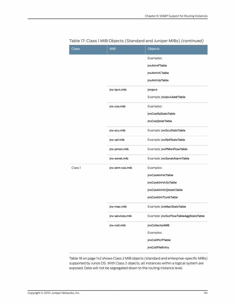
Table 17: Class 1 MIB Objects (Standard and Juniper MIBs) (continued)
ObjectsMIBClass
Examples:
jnxAtmIfTable
jnxAtmVCTable
jnxAtmVpTable
jnxipv4
Example: jnxIpv4AddrTable
jnx-ipv4.mib
Examples:
jnxCosIfqStatsTable
jnxCosQstatTable
jnx-cos.mib
Example: jnxScuStatsTablejnx-scu.mib
Example: jnxRpfStatsTablejnx-rpf.mib
Example: jnxPMonFlowTablejnx-pmon.mib
Example: jnxSonetAlarmTablejnx-sonet.mib
Examples:
jnxCosAtmVcTable
jnxCosAtmVcScTable
jnxCosAtmVcQstatsTable
jnxCosAtmTrunkTable
jnx-atm-cos.mibClass 1
Example: jnxMacStatsTablejnx-mac.mib
Example: jnxSvcFlowTableAggStatsTablejnx-services.mib
jnxCollectorMIB
Examples:
jnxCollPicIfTable
jnxCollFileEntry
jnx-coll.mib
Table 18 on page 142 shows Class 2 MIB objects (standard and enterprise-specific MIBs)
supported by Junos OS. With Class 2 objects, all instances within a logical system are
exposed. Data will not be segregated down to the routing instance level.
141Copyright © 2010, Juniper Networks, Inc.
Chapter 8: SNMP Support for Routing Instances
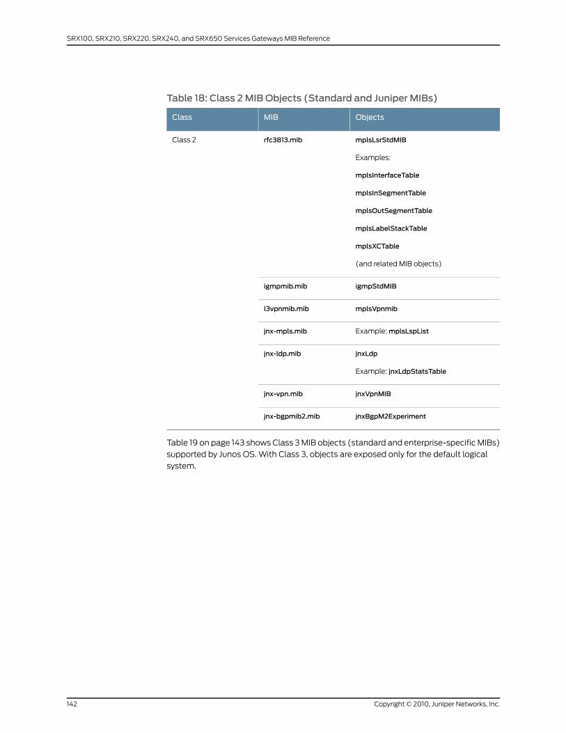
Table 18: Class 2MIB Objects (Standard and Juniper MIBs)
ObjectsMIBClass
mplsLsrStdMIB
Examples:
mplsInterfaceTable
mplsInSegmentTable
mplsOutSegmentTable
mplsLabelStackTable
mplsXCTable
(and related MIB objects)
rfc3813.mibClass 2
igmpStdMIBigmpmib.mib
mplsVpnmibl3vpnmib.mib
Example: mplsLspListjnx-mpls.mib
jnxLdp
Example: jnxLdpStatsTable
jnx-ldp.mib
jnxVpnMIBjnx-vpn.mib
jnxBgpM2Experimentjnx-bgpmib2.mib
Table 19 on page 143 shows Class 3 MIB objects (standard and enterprise-specific MIBs)
supported by Junos OS. With Class 3, objects are exposed only for the default logical
system.
Copyright © 2010, Juniper Networks, Inc.142
SRX100, SRX210, SRX220, SRX240, and SRX650 Services Gateways MIB Reference

Table 19: Class 3MIB Objects (Standard and Juniper MIBs)
ObjectsMIBClass
rmonEvents
alarmTable
logTable
eventTable
agentxMIB
rfc2819a.mibClass 3
pingmibrfc2925a.mib
tracerouteMIBrfc2925b.mib
jnxBoxAnatomyjnxchassis.mib
jnxAlarmsjnx-chassis-alarm.mib
jnxPingMIBjnx-ping.mib
jnxTraceRouteMIBjnx-traceroute.mib
jnxRmonAlarmTablejnx-rmon.mib
Example: jnxCosFcTablejnx-cos.mib
Example: jnxCfgMgmtjnx-cfgmgmt.mib
apsMIBObjectsjnx-sonetaps.mib
jnxSpMIBjnx-sp.mib
ejnmobileipABmibggsn.mib
snmpModulesrfc1907.mib
Examples:
snmpMIB snmpFrameworkMIB
snmpModules
Table 20 on page 144 shows Class 4 MIB objects (standard and enterprise-specific MIBs)
supported by Junos OS. With Class 4 objects, data is not segregated by routing instance.
All instances are exposed.
143Copyright © 2010, Juniper Networks, Inc.
Chapter 8: SNMP Support for Routing Instances
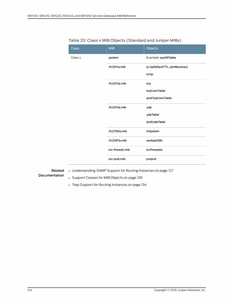
Table 20: Class 4MIB Objects (Standard and Juniper MIBs)
ObjectsMIBClass
Example: sysORTablesystemClass 4
ip (ipDefaultTTL, ipInReceives)
icmp
rfc2011a.mib
tcp
tcpConnTable
ipv6TcpConnTable
rfc2012a.mib
udp
udpTable
ipv6UdpTable
rfc2013a.mib
hrSystemrfc2790a.mib
sysApplOBJrfc2287a.mib
jnxFirewallsjnx-firewall.mib
jnxIpv6jnx-ipv6.mib
RelatedDocumentation
• Understanding SNMP Support for Routing Instances on page 127
• Support Classes for MIB Objects on page 128
• Trap Support for Routing Instances on page 134
Copyright © 2010, Juniper Networks, Inc.144
SRX100, SRX210, SRX220, SRX240, and SRX650 Services Gateways MIB Reference
CHAPTER 9
SRX100, SRX210, SRX220, SRX240, andSRX650 Services Gateways SupportedEnterprise-Specific MIBs
This chapter contains the following topic:
• List of SRX100, SRX210, SRX220, SRX240, and SRX650 Services Gateways Supported
Enterprise-Specific MIBs on page 145
ListofSRX100,SRX210,SRX220,SRX240,andSRX650ServicesGatewaysSupportedEnterprise-Specific MIBs
Junos OS supports the following enterprise-specific MIBs:
• Structure of Management Information MIB—Contains object identifiers (OIDs) for the
security branch of the MIBs used in Junos OS for J Series and SRX Series devices product,
services and traps. This MIB is currently supported only by Junos OS for J Series and
SRX Series devices. It also explains how the Juniper Networks enterprise-specific MIBs
are structured. For a downloadable version of this MIB, see
http://www.juniper.net/techpubs/en_US/junos10.4/information-products/
topic-collections/reference-mibs-and-traps/mib-jnx-js-smi.txt. For more information,
see “Structure of Management Information MIB” on page 153.
• Access Authentication Objects MIB—Provides support for monitoring firewall
authentication, including data about the users trying to access firewall-protected
resources and the firewall authentication service itself. This MIB is currently supported
only by Junos OS for J Series and SRX Series devices. For a downloadable version of
this MIB, see http://www.juniper.net/techpubs/en_US/junos10.4/information-products/
topic-collections/reference-mibs-and-traps/mib-jnx-js-auth.txt .
For more information, see “Access Authentication Objects MIB” on page 161.
• Alarm MIB—Provides support for alarms from the router. For a downloadable version
of this MIB, seehttp://www.juniper.net/techpubs/en_US/junos10.4/information-products/
topic-collections/reference-mibs-and-traps/mib-jnx-chassis-alarm.txt .
For more information, see “Alarm MIB” on page 165.
• BGP4 V2 MIB—Contains objects used to monitor BGP peer-received prefix counters.
It is based upon similar objects in the MIB documented in Internet draft
145Copyright © 2010, Juniper Networks, Inc.
draft-ietf-idr-bgp4-mibv2-03.txt, Definitions of Managed Objects for the Fourth Version
of BGP (BGP-4), Second Version. For a downloadable version of this MIB, see
http://www.juniper.net/techpubs/en_US/junos10.4/information-products/
topic-collections/reference-mibs-and-traps/mib-jnx-bgpmib2.txt .
For more information, see “BGP4 V2 MIB” on page 169.
• BFD MIB—Provides support for monitoring Bidirectional Forwarding Detection (BFD)
sessions. For a downloadable version of this MIB, see
http://www.juniper.net/techpubs/en_US/junos10.4/information-products/
topic-collections/reference-mibs-and-traps/mib-jnx-bfd.txt .
For more information, see “Bidirectional Forwarding Detection (BFD) MIB” on page 171.
• Chassis MIB—Provides support for environmental monitoring (power supply state,
board voltages, fans, temperatures, and air flow) and inventory support for the chassis,
System Control Board (SCB), System and Switching Board (SSB), Switching and
Forwarding Model (SFM), Flexible PIC Concentrators (FPCs), and PICs. For a
downloadable version of this MIB, see
http://www.juniper.net/techpubs/en_US/junos10.4/information-products/
topic-collections/reference-mibs-and-traps/mib-jnx-chassis.txt .
For more information, see “Chassis MIBs” on page 173.
• Configuration Management MIB—Provides notification for configuration changes as
SNMP traps. Each trap contains the time at which the configuration change was
committed, the name of the user who made the change, and the method by which the
change was made. A history of the last 32 configuration changes is kept in
jnxCmChgEventTable. For a downloadable version of this MIB, see
http://www.juniper.net/techpubs/en_US/junos10.4/information-products/
topic-collections/reference-mibs-and-traps/mib-jnx-cfgmgmt.txt .
For more information, see “Configuration Management MIB” on page 269.
• Ethernet MAC MIB—Monitors media access control (MAC) statistics on Gigabit Ethernet
intelligent queuing (IQ) interfaces. It collects MAC statistics; for example, inoctets,
inframes,outoctets, andoutframeson each source MAC address and virtual LAN (VLAN)
ID for each Ethernet port. For a downloadable version of this MIB, see
http://www.juniper.net/techpubs/en_US/junos10.4/information-products/
topic-collections/reference-mibs-and-traps/mib-jnx-mac.txt .
For more information, see “Ethernet MAC MIB” on page 275.
• Event MIB—Defines a generic trap that can be generated using an op script or event
policy. This MIB provides the ability to specify a system log string and raise a trap if
that system log string is found. For a downloadable version of this MIB, see
http://www.juniper.net/techpubs/en_US/junos10.4/information-products/
topic-collections/reference-mibs-and-traps/mib-jnx-event.txt .
For more information, see “Event MIB” on page 277.
• Firewall MIB—Provides support for monitoring firewall filter counters. Routers must
have the Internet Processor II ASIC to perform firewall monitoring. For a downloadable
version of this MIB, see
http://www.juniper.net/techpubs/en_US/junos10.4/information-products/
Copyright © 2010, Juniper Networks, Inc.146
SRX100, SRX210, SRX220, SRX240, and SRX650 Services Gateways MIB Reference

topic-collections/reference-mibs-and-traps/mib-jnx-firewall.txt .
For more information, see “Firewall MIB” on page 279.
• Host Resources MIB—Extends the hrStorageTable object, providing a measure of the
usage of each file system on the router in percentage. Previously, the objects in the
hrStorageTable measured the usage in allocation units—hrStorageUsed and
hrStorageAllocationUnits—only. Using the percentage measurement, you can more
easily monitor and apply thresholds on usage. For a downloadable version of this MIB,
see http://www.juniper.net/techpubs/en_US/junos10.4/information-products/
topic-collections/reference-mibs-and-traps/mib-jnx-hostresources.txt .
For more information, see “Host Resources MIB” on page 283.
• Interface MIB—Extends the standard ifTable (RFC 2863) with additional statistics and
Juniper Networks enterprise-specific chassis information. For a downloadable version
of this MIB, seehttp://www.juniper.net/techpubs/en_US/junos10.4/information-products/
topic-collections/reference-mibs-and-traps/mib-jnx-if-extensions.txt .
For more information, see “Interface MIB” on page 285.
• IP Forward MIB—Extends the standard IP Forwarding Table MIB (RFC 2096) to include
CIDR forwarding information. For a downloadable version of this MIB, see
http://www.juniper.net/techpubs/en_US/junos10.4/information-products/
topic-collections/reference-mibs-and-traps/mib-jnx-ipforward.txt .
For more information, see “IP Forward MIB” on page 291.
• IPsec Monitoring MIB—Provides operational and statistical information related to the
IPsec and IKE tunnels on Juniper Networks routers. For a downloadable version of this
MIB, see http://www.juniper.net/techpubs/en_US/junos10.4/information-products/
topic-collections/reference-mibs-and-traps/mib-jnx-ipsec-monitor-asp.txt .
For more information, see “IPSec Monitoring MIB” on page 309.
• IPsec Generic Flow Monitoring Object MIB—Based on jnx-ipsec-monitor-mib, this MIB
provides support for monitoring IPsec and IPsec VPN management objects. This MIB
is currently supported only by Junos OS for J Series and SRX Series devices. For a
downloadable version of this MIB, see
http://www.juniper.net/techpubs/en_US/junos10.4/information-products/
topic-collections/reference-mibs-and-traps/mib-jnx-ipsec-flow-mon.txt .
For more information, see “IPsec Generic Flow Monitoring Object MIB” on page 293.
• IPv4 MIB—Provides additional Internet Protocol version 4 (IPv4) address information,
supporting the assignment of identical IPv4 addresses to separate interfaces. For a
downloadable version of this MIB, see
http://www.juniper.net/techpubs/en_US/junos10.4/information-products/
topic-collections/reference-mibs-and-traps/mib-jnx-ipv4.txt .
For more information, see “IPv4 MIB” on page 317.
• Network Address Translation (NAT) Objects MIB—Provides support for monitoring
network address translation (NAT). This MIB is currently supported only by Junos OS
for J Series and SRX Series devices. For a downloadable version of this MIB, see
http://www.juniper.net/techpubs/en_US/junos10.4/information-products/
147Copyright © 2010, Juniper Networks, Inc.
Chapter 9: SRX100, SRX210, SRX220, SRX240, and SRX650 Services Gateways Supported Enterprise-Specific MIBs

topic-collections/reference-mibs-and-traps/mib-jnx-js-nat.txt .
For more information, see “Network Address Translation Objects MIB” on page 327.
• Packet Forwarding Engine MIB—Provides notification statistics for Packet Forwarding
Engines. For a downloadable version of this MIB, see
http://www.juniper.net/techpubs/en_US/junos10.4/information-products/
topic-collections/reference-mibs-and-traps/mib-jnx-pfe.txt .
For more information, see “Packet Forwarding Engine MIB” on page 335.
• Ping MIB—Extends the standard Ping MIB control table (RFC 2925). Items in this MIB
are created when entries are created in pingCtlTable of the Ping MIB. Each item is
indexed exactly as it is in the Ping MIB. For a downloadable version of this MIB, see
http://www.juniper.net/techpubs/en_US/junos10.4/information-products/
topic-collections/reference-mibs-and-traps/mib-jnx-ping.txt .
For more information, see “PING MIB” on page 339.
• Policy Objects MIB—Provides support for monitoring the security policies that control
the flow of traffic from one zone to another. This MIB is currently supported only by
Junos OS for J Series and SRX Series devices. For a downloadable version of this MIB,
see http://www.juniper.net/techpubs/en_US/junos10.4/information-products/
topic-collections/reference-mibs-and-traps/mib-jnx-js-policy.txt .
For more information, see “Policy Objects MIB” on page 355.
• Real-Time Media MIB—Defines a Real-Time Media configuration. For a downloadable
version of this MIB, see
http://www.juniper.net/techpubs/en_US/junos10.4/information-products/
topic-collections/reference-mibs-and-traps/mibjnx-rtm.txt .
For more information, see “Real-Time Media MIB Overview” on page 361.
• Reverse-Path-Forwarding MIB—Monitors statistics for traffic that is rejected because
of reverse-path-forwarding (RPF) processing. For a downloadable version of this MIB,
see http://www.juniper.net/techpubs/en_US/junos10.4/information-products/
topic-collections/reference-mibs-and-traps/mib-jnx-rpf.txt .
NOTE: The enterprise-specific RPFMIB is not supported on EX SeriesEthernet Switches.
For more information, see “Reverse Path Forwarding MIB” on page 371.
• RMON Events and Alarms MIB—Supports the Junos extensions to the standard Remote
Monitoring (RMON) Events and Alarms MIB (RFC 2819). The extension augments
alarmTable with additional information about each alarm. Two new traps are also
defined to indicate when problems are encountered with an alarm. For a downloadable
version of this MIB, see
http://www.juniper.net/techpubs/en_US/junos10.4/information-products/
topic-collections/reference-mibs-and-traps/mib-jnx-rmon.txt .
For more information, see “RMON Events and Alarms MIB” on page 373.
Copyright © 2010, Juniper Networks, Inc.148
SRX100, SRX210, SRX220, SRX240, and SRX650 Services Gateways MIB Reference
• Security Interface Extension Objects MIB—Provides support for the security
management of interfaces. This MIB is currently supported only by Junos OS for J Series
and SRX Series devices. For a downloadable version of this MIB, see
http://www.juniper.net/techpubs/en_US/junos10.4/information-products/
topic-collections/reference-mibs-and-traps/mib-jnx-js-if-ext.txt .
For more information, see “Security Interface Extension Objects MIB” on page 377.
• SIP Common MIB—Defines objects that are common to all SIP entities. For a
downloadable version of this MIB, see
http://www.juniper.net/techpubs/en_US/junos10.4/information-products/
topic-collections/reference-mibs-and-traps/mib-jnx-sipcommon.txt.
For more information, see “SIP Common MIB Overview” on page 381.
• SNMP IDP Objects MIB—Provides support for monitoring SNMP IDP queries, requests,
responses, and failures. This MIB defines the key monitoring and threshold crossing
trap support, IDP database update status and trap support, attack-related monitoring
and trap support for SRX100, SRX210, SRX220, SRX240, and SRX650 Services
Gateways. This MIB models IDP attributes specific to the appropriate Juniper Networks
implementation. For a downloadable version of this MIB, see
http://www.juniper.net/techpubs/en_US/junos10.4/information-products/
topic-collections/reference-mibs-and-traps/jnx-js-idp.mib.txt .
For more information, see “IDP MIB” on page 387.
• SPU Monitoring MIB—Provides support for monitoring SPUs on SRX5600 and SRX5800
devices. For a downloadable version of this MIB, see
http://www.juniper.net/techpubs/en_US/junos10.4/information-products/
topic-collections/reference-mibs-and-traps/mib-jnx-js-spu-monitoring.txt .
For more information, see SPU Monitoring MIB.
• System Log MIB—Enables notification of an SNMP trap-based application when an
important system log message occurs. For a downloadable version of this MIB, see
http://www.juniper.net/techpubs/en_US/junos10.4/information-products/
topic-collections/reference-mibs-and-traps/mib-jnx-syslog.txt .
For more information, see “System Log MIB” on page 389.
• Traceroute MIB—Supports the Junos extensions of traceroute and remote operations.
Items in this MIB are created when entries are created in the traceRouteCtlTable of
the Traceroute MIB. Each item is indexed exactly the same way as it is in the Traceroute
MIB. For a downloadable version of this MIB, see
http://www.juniper.net/techpubs/en_US/junos10.4/information-products/
topic-collections/reference-mibs-and-traps/mib-jnx-traceroute.txt .
For more information, see “Traceroute MIB” on page 393.
• Utility MIB—Provides SNMP support for exposing Junos data and has tables that contain
information on each type of data, such as integer and string. For a downloadable version
of this MIB, seehttp://www.juniper.net/techpubs/en_US/junos10.4/information-products/
topic-collections/reference-mibs-and-traps/mib-jnx-util.txt .
149Copyright © 2010, Juniper Networks, Inc.
Chapter 9: SRX100, SRX210, SRX220, SRX240, and SRX650 Services Gateways Supported Enterprise-Specific MIBs

For more information, see “Utility MIB” on page 395.
• VPN Certificate Objects MIB—Provides support for monitoring the local and CA
certificates loaded on the router. This MIB is currently supported only by Junos OS for
J Series and SRX Series devices. For a downloadable version of this MIB, see
http://www.juniper.net/techpubs/en_US/junos10.4/information-products/
topic-collections/reference-mibs-and-traps/mib-jnx-js-cert.txt .
For more information, see “VPN Certificate Objects MIB” on page 399.
Copyright © 2010, Juniper Networks, Inc.150
SRX100, SRX210, SRX220, SRX240, and SRX650 Services Gateways MIB Reference
PART 3
SRX100, SRX210, SRX220, SRX240, andSRX650 Services Gateways MIBs
• Interpreting the Structure of Management Information MIB on page 153
• Interpreting the Enterprise-Specific Access Authentication Objects MIB on page 161
• Interpreting the Enterprise-Specific Alarm MIB on page 165
• Interpreting the Enterprise-Specific BGP4 V2 MIB on page 169
• Interpreting the Enterprise-Specific Bidirectional Forwarding Detection
(BFD) MIB on page 171
• Interpreting the Enterprise-Specific Chassis MIBs on page 173
• Interpreting the Enterprise-Specific Configuration Management MIB on page 269
• Interpreting the Enterprise-Specific Ethernet MAC MIB on page 275
• Interpreting the Enterprise-Specific Event MIB on page 277
• Interpreting the Enterprise-Specific Firewall MIB on page 279
• Interpreting the Enterprise-Specific Host Resources MIB on page 283
• Interpreting the Enterprise-Specific Interface MIB on page 285
• Interpreting the Enterprise-Specific IP Forward MIB on page 291
• Interpreting the Enterprise-Specific IPsec Generic Flow Monitoring Object
MIB on page 293
• Interpreting the Enterprise-Specific IPsec Monitoring MIB on page 309
• Interpreting the Enterprise-Specific IPv4 MIB on page 317
• Interpreting the Enterprise-Specific IPv6 MIB on page 319
• Interpreting the Enterprise-Specific Network Address Translation Objects
MIB on page 327
• Interpreting the Enterprise-Specific Packet Forwarding Engine MIB on page 335
• Interpreting the Enterprise-Specific Ping MIB on page 339
• Interpreting the Enterprise-Specific Policy Objects MIB on page 355
• Interpreting the Enterprise-Specific Real-Time Media MIB on page 361
• Interpreting the Enterprise-Specific Reverse-Path-Forwarding MIB on page 371
• Interpreting the Enterprise-Specific RMON Events and Alarms MIB on page 373
• Interpreting the Enterprise-Specific Security Interface Extension Objects MIB on page 377
151Copyright © 2010, Juniper Networks, Inc.

• Interpreting the Enterprise-Specific SIP Common MIB on page 381
• Interpreting the Enterprise-Specific SNMP IDP MIB on page 387
• Interpreting the Enterprise-Specific System Log MIB on page 389
• Interpreting the Enterprise-Specific Traceroute MIB on page 393
• Interpreting the Enterprise-Specific Utility MIB on page 395
• Interpreting the Enterprise-Specific VPN Certificate Objects MIB on page 399
Copyright © 2010, Juniper Networks, Inc.152
SRX100, SRX210, SRX220, SRX240, and SRX650 Services Gateways MIB Reference
CHAPTER 10
Interpreting theStructure ofManagementInformation MIB
This chapter contains the following topics:
• Structure of Management Information MIB on page 153
• jnxProducts on page 154
• jnxServices on page 154
• jnxMibs on page 155
• jnxTraps on page 157
• jnxExperiment on page 158
Structure of Management InformationMIB
The Juniper Networks enterprise-specific Structure of Management Information MIB
defines the top-level structure of the Juniper Networks enterprise-specific MIB space.
For a downloadable version of this MIB, see
http://www.juniper.net/techpubs/en_US/junos10.4/topics/reference/mibs/mib-jnx-smi.txt
.
The Structure of Management Information MIB space has five root branches:
• jnxProducts on page 154
• jnxServices on page 154
• jnxMibs on page 155
• jnxTraps on page 157
• jnxExperiment on page 158
RelatedDocumentation
Juniper Networks Enterprise-Specific SNMP Traps•
• Standard SNMP Traps Supported on Devices Running Junos OS
• Juniper Networks Enterprise-Specific MIBs on page 23
• Standard SNMP MIBs Supported by Junos OS on page 12
153Copyright © 2010, Juniper Networks, Inc.
jnxProducts
The object identifier for the jnxProducts root branch of the Structure of Management
Information MIB is {juniperMIB 1}. This branch of the MIB describes the Juniper Networks
routers and their components, such as product line, product name, model, number of
slots, and media space for holding PICs. It also provides information about the system’s
power supply state, board voltages, fans, temperatures, and air flow. In general, this
branch of the Structure of Management Information MIB is rarely polled for information
because it is descriptive. However, you can poll this branch of the Structure of
Management Information MIB to determine the sysObjectId of a router as defined by
MIB-II.
jnxProducts 1 is reserved for Junos OS-based products.
RelatedDocumentation
Structure of Management Information MIB on page 153•
• jnxServices on page 154
• jnxMibs on page 155
• jnxTraps on page 157
• jnxExperiment on page 158
jnxServices
The object identifier for the jnxServices root branch is {juniperMIB 2}. This MIB file added
the nodes to create the Juniper Networks security tree structure under the object node
jnxJsObjects. In general, the prefix jnxJs is used to name the object identifiers and to
designate them. This branch of the network describes the Juniper Networks services
objects that provide enhanced network security. This MIB is currently supported by Junos
OS for J Series and SRX Series devices only.
The jnxJsSecurity node is designed to provide a branch for the security-related MIB
defintions specific to the Juniper Networks security products. The next level object
identifiers under jnxJsSecurity are:
• jnxJsIf—Whose object identifier is {jnxJsSecurity 1}.
• jnxJsAuth—Whose object identifier is {jnxJsSecurity 2}.
• jnxJsCertificates—Whose object identifier is {jnxJsSecurity 3}.
• jnxJsPolicies—Whose object identifier is {jnxJsSecurity 4}.
• jnxJsIPSecVpn—Whose object identifier is {jnxJsSecurity 5}.
• jnxJsResources—Whose object identifier is {jnxJsSecurity 6}.
• jnxJsNAT—Whose object identifier is {jnxJsSecurity 7}.
• jnxJsScreening—Whose object identifier is {jnxJsSecurity 8}.
Copyright © 2010, Juniper Networks, Inc.154
SRX100, SRX210, SRX220, SRX240, and SRX650 Services Gateways MIB Reference
• jnxJsDhcp—Whose object identifier is {jnxJsSecurity 9}.
• jnxJsDnsRoot—Whose object identifier is {jnxJsSecurity 10}.
The Juniper Networks enterprise-specific security MIBs include:
• AAA Objects MIB—Whose object identifier is {jnxUserAAAMibRoot 1}.
• Access Authentication Objects MIB—Whose object identifier is {jnxJsAuth 1}.
• DNS Objects MIB—Whose object identifier is {jnxJsDns 1}.
• IPsec Generic Flow Monitoring Objects MIB—Whose object identifier is {jnxIpSecMibRoot
1}.
• IPsec VPN Objects MIB—Whose object identifier is {jnxJsIPSecVpn 1}.
• Network Address Translation Objects MIB—Whose object identifier is {jnxJsNAT 1}.
• Policy Objects MIB—Whose object identifier is {jnxJsPolicies 1}.
• Security Interface Extension Objects MIB—Whose object identifier is {jnxJsIf 1}.
• VPN Certificate Objects MIB—Whose object identifier is {jnxJsCertificates 1}.
• Security Screening Objects MIB—Whose object identifier is {jnxJsScreening 1}.
For more information about these MIBs, see “Juniper Networks Enterprise-Specific MIBs”
on page 23.
RelatedDocumentation
Structure of Management Information MIB on page 153•
• jnxProducts on page 154
• jnxMibs on page 155
• jnxTraps on page 157
• jnxExperiment on page 158
jnxMibs
The object identifier for the jnxMibs root branch is {juniperMIB 3} and includes one main
subbranch, jnxBoxAnatomy, whose object identifier is {jnxMibs 1}. The other Juniper
Networks enterprise-specific MIBs are also branches of jnxMibs. These Juniper Networks
enterprise-specific MIBs include:
• MPLS MIB—Whose object identifier is {jnxMibs 2}.
• Juniper Networks enterprise-specific extensions to the Interface MIB—Whose object
identifier is {jnxMibs 3}.
• Alarm MIB—Whose object identifier is {jnxMibs 4}.
• Firewall MIB—Whose object identifier is {jnxMibs 5}.
• Destination Class Usage MIB—Whose object identifier is {jnxMibs 6}.
155Copyright © 2010, Juniper Networks, Inc.
Chapter 10: Interpreting the Structure of Management Information MIB
• Juniper Networks enterprise-specific extensions to the Ping MIB—Whose object identifier
is {jnxMibs 7}.
• Juniper Networks enterprise-specific extensions to the Traceroute MIB—Whose object
identifier is {jnxMibs 8}.
• ATM MIB—Whose object identifier is {jnxMibs 10}.
• IPv6 and ICMPv6 MIB—Whose object identifier is {jnxMibs 11}.
• IPv4 MIB—Whose object identifier is {jnxMibs 12}.
• Juniper Networks enterprise-specific extensions to the RMON Events and Alarms
MIB—Whose object identifier is {jnxMIBs 13}.
• Juniper Networks enterprise-specific extensions to the LDP traps MIB—Whose object
identifier is {jnxMibs 14}.
• Class-of-service MIB—Whose object identifier is {jnxMibs 15}.
• Source class usage MIB—Whose object identifier is {jnxMibs 16}.
• Reverse-path-forwarding MIB—Whose object identifier is {jnxMibs 17}.
• Configuration management MIB—Whose object identifier is {jnxMibs 18}.
• Passive monitoring MIB—Whose object identifier is {jnxMibs 19}.
• SONET/SDH Interface Management MIB—Whose object identifier is {jnxMibs 20}.
• ATM class-of-service MIB—Whose object identifier is {jnxMibs 21}.
• IPsec Monitoring MIB—Whose object identifier is {jnxMibs 22}.
• Ethernet MAC MIB—Whose object identifier is {jnxMibs 23}.
• SONET APS MIB—Whose object identifier is {jnxMibs 24}.
• Chassis Definitions for Router Model MIB—Whose object identifier is {jnxMibs 25}.
• VPN MIB—Whose object identifier is {jnxMibs 26}.
• Flow Collection Services MIB—Whose object identifier is {jnxMibs 28} .
• RSVP Traffic Engineering (TE) MIB—Whose object identifier is {jnxMibs 30}.
• Host Resources MIB—Whose object identifier is {jnxMibs 31}.
• Services PIC MIB—Whose object identifier is {jnxMibs 32}.
• Dynamic Flow Capture (DFC) MIB—Whose object identifier is {jnxMibs 33}.
• Chassis Forwarding MIB—Whose object identifier is {jnxMibs 34}.
• System Log MIB—Whose object identifier is {jnxMibs 35}.
• MPLS LDP MIB—Whose object identifier is {jnxMibs 36}.
• Event MIB—Whose object identifier is {jnxMibs 37}.
• IP Forward MIB—Whose object identifier is {jnxMibs 38}.
• jnxJSMibRoot—Whose object identifier is {jnxMibs 39}
Copyright © 2010, Juniper Networks, Inc.156
SRX100, SRX210, SRX220, SRX240, and SRX650 Services Gateways MIB Reference
• jnxEXMibRoot—Whose object identifier is {jnxMibs 40}
• jnxWXMibRoot—Whose object identifier is {jnxMibs 41}
• Packet Forwarding Engine MIB—Whose object identifier is {jnxMibs 44}.
• BFD MIB—Whose object identifier is {jnxMibs 45}.
• Utility MIB—Whose object identifier is {jnxMibs 47}.
• L2ALD MIB—Whose object identifier is {jnxMibs 48}.
• L2TP MIB—Whose object identifier is {jnxMibs 49}.
• RPM MIB—Whose object identifier is {jnxMibs 50}.
• User AAA MIB—Whose object identifier is {jnxMibs 51}.
• Juniper generic IPsec MIB—Whose object identifier is {jnxMibs 52}.
• L2 control protocols MIB—Whose object identifier is {jnxMibs 53}.
• Pseudowire TDM MIB—Whose object identifier is {jnxMibs 54}.
• Pseudowire TC MIB—Whose object identifier is {jnxMibs 55}.
• OTN MIB—Whose object identifier is {jnxMibs 56}.
For more information about these MIBs, see “Juniper Networks Enterprise-Specific MIBs”
on page 23.
RelatedDocumentation
Structure of Management Information MIB on page 153•
• jnxProducts on page 154
• jnxServices on page 154
• jnxTraps on page 157
• jnxExperiment on page 158
jnxTraps
The object identifier for the jnxTraps root branch of the Structure of Management
Information MIB is {juniperMIB4}. The jnxTraps root branch contains the enterprise-specific
SNMP traps supported by Junos OS. These Juniper Networks enterprise-specific SNMP
traps include:
• jnxChassisTraps—Whose object identifier is {jnxTraps 1}.
• jnxChassisOKTraps—Whose object identifier is {jnxTraps 2}.
• jnxRmonTraps—Whose object identifier is {jnxTraps 3}.
• jnxLdpTraps—Whose object identifier is {jnxTraps 4}.
• jnxCmNotifications—Whose object identifier is {jnxTraps 5}.
• jnxSonetNotifications—Whose object identifier is {jnxTraps 6}.
157Copyright © 2010, Juniper Networks, Inc.
Chapter 10: Interpreting the Structure of Management Information MIB
• jnxPMonNotifications— Whose object identifier is {jnxTraps 7}
• jnxCollectorNotifications—Whose object identifier is {jnxTraps 8}.
• jnxPingNotification—Whose object identifier is {jnxTraps 9}.
• jnxSpNotification—Whose object identifier is {jnxTraps10}.
• jnxDfcNotifications—Whose object identifier is {jnxTraps11}.
• jnxSyslogNotifications—Whose object identifier is {jnxTraps12}.
• jnxEventNotifications—Whose object identifier is {jnxTraps13}.
• jnxVccpNotifications—Whose object identifier is {jnxTraps14}.
• jnxOtnNotifications—Whose object identifier is {jnxTraps15}.
RelatedDocumentation
Structure of Management Information MIB on page 153•
• jnxProducts on page 154
• jnxServices on page 154
• jnxMibs on page 155
• jnxExperiment on page 158
jnxExperiment
The object identifier for the jnxExperiment root branch of the Structure of Management
Information MIB is {juniperMIB 5}. The jnxExperiment root branch contains experimental
Juniper Networks enterprise-specific MIBs. This is the top-level object identifier registry
used by Juniper Networks products for SNMP modules containing experimental MIB
definitions.
jnxExperiment MIBs are defined as the following MIBs:
• IETF work-in-process MIBs that have not been assigned a permanent object identifier
by the IANA.
• Juniper Networks work-in-process MIBs that have not achieved final production quality
or field experience.
The following draft supports the jnxExperiment MIB space: Internet draft
draft-ietf-idr-bgp4-mibv2-03.txt, Definitions of Managed Objects for the Fourth Version
of Border Gateway Protocol (BGP-4), Second Version (jnxBgpM2PrefixInPrefixes,
jnxBgpM2PrefixInPrefixesAccepted, and jnxBgpM2PrefixInPrefixesRejected objects only).
RelatedDocumentation
• Structure of Management Information MIB on page 153
• jnxProducts on page 154
• jnxServices on page 154
• jnxMibs on page 155
Copyright © 2010, Juniper Networks, Inc.158
SRX100, SRX210, SRX220, SRX240, and SRX650 Services Gateways MIB Reference

• jnxTraps on page 157
159Copyright © 2010, Juniper Networks, Inc.
Chapter 10: Interpreting the Structure of Management Information MIB

Copyright © 2010, Juniper Networks, Inc.160
SRX100, SRX210, SRX220, SRX240, and SRX650 Services Gateways MIB Reference
CHAPTER 11
Interpreting theEnterprise-SpecificAccessAuthentication Objects MIB
This chapter contains the following topics:
• Access Authentication Objects MIB on page 161
• jnxJsFwAuthStats on page 161
• jnxJsAuthTrapVars on page 162
• jnxJsAuthNotifications on page 163
Access Authentication Objects MIB
The Juniper Networks enterprise-specific Access Authentication Objects MIB, whose
object ID is {jnxJsAuth1}, defines the objects that pertain to access authentication. Firewall
and security features restrict the accessing of protected resources (ideally on different
zones) behind a firewall based on their source IP and other credentials.
For a downloadable version of this MIB, see
http://www.juniper.net/techpubs/en_US/junos10.4/topics/reference/mibs/mib-jnx-js-auth.txt
.
For information about the enterprise-specific Access Authentication Objects MIB, see
the following topics:
• jnxJsFwAuthStats on page 161
• jnxJsAuthTrapVars on page 162
• jnxJsAuthNotifications on page 163
RelatedDocumentation
Juniper Networks Enterprise-Specific MIBs on page 23•
• Standard SNMP MIBs Supported by Junos OS on page 12
jnxJsFwAuthStats
jnxJsFwAuthStats, whose object ID is {jnxJsAuthObjects 1}, exposes the firewall
authentication statistics listed in Table 21 on page 162.
161Copyright © 2010, Juniper Networks, Inc.
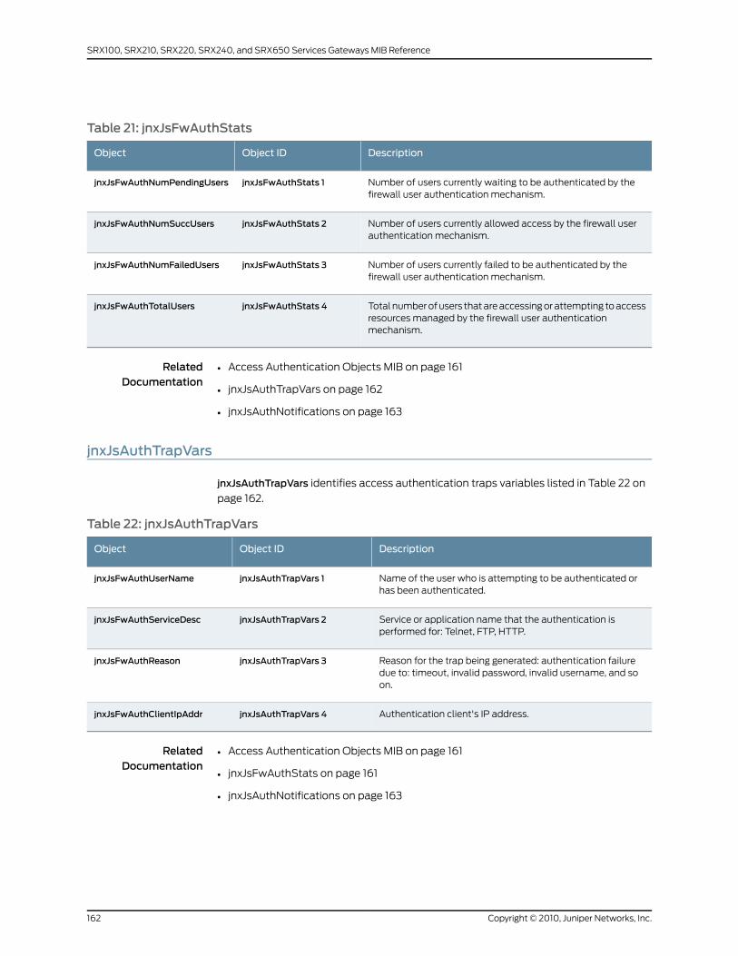
Table 21: jnxJsFwAuthStats
DescriptionObject IDObject
Number of users currently waiting to be authenticated by thefirewall user authentication mechanism.
jnxJsFwAuthStats 1jnxJsFwAuthNumPendingUsers
Number of users currently allowed access by the firewall userauthentication mechanism.
jnxJsFwAuthStats 2jnxJsFwAuthNumSuccUsers
Number of users currently failed to be authenticated by thefirewall user authentication mechanism.
jnxJsFwAuthStats 3jnxJsFwAuthNumFailedUsers
Total number of users that are accessing or attempting to accessresources managed by the firewall user authenticationmechanism.
jnxJsFwAuthStats 4jnxJsFwAuthTotalUsers
RelatedDocumentation
Access Authentication Objects MIB on page 161•
• jnxJsAuthTrapVars on page 162
• jnxJsAuthNotifications on page 163
jnxJsAuthTrapVars
jnxJsAuthTrapVars identifies access authentication traps variables listed in Table 22 on
page 162.
Table 22: jnxJsAuthTrapVars
DescriptionObject IDObject
Name of the user who is attempting to be authenticated orhas been authenticated.
jnxJsAuthTrapVars 1jnxJsFwAuthUserName
Service or application name that the authentication isperformed for: Telnet, FTP, HTTP.
jnxJsAuthTrapVars 2jnxJsFwAuthServiceDesc
Reason for the trap being generated: authentication failuredue to: timeout, invalid password, invalid username, and soon.
jnxJsAuthTrapVars 3jnxJsFwAuthReason
Authentication client's IP address.jnxJsAuthTrapVars 4jnxJsFwAuthClientIpAddr
RelatedDocumentation
Access Authentication Objects MIB on page 161•
• jnxJsFwAuthStats on page 161
• jnxJsAuthNotifications on page 163
Copyright © 2010, Juniper Networks, Inc.162
SRX100, SRX210, SRX220, SRX240, and SRX650 Services Gateways MIB Reference
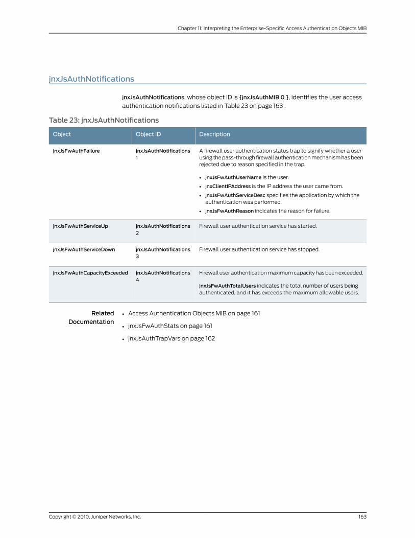
jnxJsAuthNotifications
jnxJsAuthNotifications, whose object ID is {jnxJsAuthMIB 0 }, identifies the user access
authentication notifications listed in Table 23 on page 163 .
Table 23: jnxJsAuthNotifications
DescriptionObject IDObject
A firewall user authentication status trap to signify whether a userusing the pass-through firewall authentication mechanism has beenrejected due to reason specified in the trap.
• jnxJsFwAuthUserName is the user.
• jnxClientIPAddress is the IP address the user came from.
• jnxJsFwAuthServiceDesc specifies the application by which theauthentication was performed.
• jnxJsFwAuthReason indicates the reason for failure.
jnxJsAuthNotifications1
jnxJsFwAuthFailure
Firewall user authentication service has started.jnxJsAuthNotifications2
jnxJsFwAuthServiceUp
Firewall user authentication service has stopped.jnxJsAuthNotifications3
jnxJsFwAuthServiceDown
Firewall user authentication maximum capacity has been exceeded.
jnxJsFwAuthTotalUsers indicates the total number of users beingauthenticated, and it has exceeds the maximum allowable users.
jnxJsAuthNotifications4
jnxJsFwAuthCapacityExceeded
RelatedDocumentation
• Access Authentication Objects MIB on page 161
• jnxJsFwAuthStats on page 161
• jnxJsAuthTrapVars on page 162
163Copyright © 2010, Juniper Networks, Inc.
Chapter 11: Interpreting the Enterprise-Specific Access Authentication Objects MIB

Copyright © 2010, Juniper Networks, Inc.164
SRX100, SRX210, SRX220, SRX240, and SRX650 Services Gateways MIB Reference
CHAPTER 12
Interpreting theEnterprise-Specific AlarmMIB
• Alarm MIB on page 165
• jnxAlarmRelayMode on page 165
• jnxYellowAlarms on page 166
• jnxRedAlarms on page 167
AlarmMIB
The Juniper Networks enterprise-specific Alarm MIB, whose object identifier is {jnxMibs
4}, contains information about alarms from the router chassis.
For a downloadable version of this MIB, see
http://www.juniper.net/techpubs/en_US/junos10.4/topics/reference/mibs/mib-jnx-chassis-alarm.txt
.
For information about the enterprise-specific Alarm MIB objects, see the following topics:
• jnxAlarmRelayMode on page 165
• jnxYellowAlarms on page 166
• jnxRedAlarms on page 167
RelatedDocumentation
Juniper Networks Enterprise-Specific MIBs on page 23•
• Standard SNMP MIBs Supported by Junos OS on page 12
jnxAlarmRelayMode
The jnxAlarmRelayMode, whose object identifier is {jnxCraftAlarms 1}, denotes the alarm
relay mode of the craft interface panel for the yellow and red alarms. This object uses
the following integer values:
• 1–Other: Other or unknown state
• 2–passOn: Alarms are passed on. The alarm relay is activated to pass on the yellow
or red alarms to audible sirens or visual flashing devices.
165Copyright © 2010, Juniper Networks, Inc.

• 3–cutOff: Alarms are turned off. Both the yellow and red alarms are cut off from the
alarm relays and do not get passed on to audible sirens or visual flashing devices.
NOTE: Both the yellow and red alarms can be cut off from the alarm relayusing a Alarm Cutoff/Lamp Test button on the front panel of the routerchassis.
RelatedDocumentation
Alarm MIB on page 165•
• jnxYellowAlarms on page 166
• jnxRedAlarms on page 167
jnxYellowAlarms
The jnxYellowAlarms, whose object identifier is {jnxCraftAlarms 2} contains the objects
listed in Table 24 on page 166.
Table 24: jnxYellowAlarms
DescriptionObject IDObject
Denotes the yellow alarm state on the craft interface panel of the routerchassis. This object contains one of the following integer values:
• other–1: The alarm state is unknown.
• off–2: The yellow alarms are off. You can turn off the yellow alarms usingthe Alarm Cutoff/Lamp Test button on the craft interface panel of therouter chassis.
• on–3: The yellow alarms are on.
jnxYellowAlarms 1jnxYellowAlarmState
Shows the number of currently active and nonsilent yellow alarms.
NOTE: The value of this object is independent of the state of the AlarmCutoff/Lamp Test button.
jnxYellowAlarms 2jnxYellowAlarmCount
Shows the value of the sysUp time when the state of the yellow alarm lastchanged from on to off or vice versa. This object returns0 if the alarm statehas not changed since the sysUp time was reset last time, or if the value isunknown.
jnxYellowAlarms 3jnxYellowAlarmLastChange
RelatedDocumentation
Alarm MIB on page 165•
• jnxAlarmRelayMode on page 165
• jnxRedAlarms on page 167
Copyright © 2010, Juniper Networks, Inc.166
SRX100, SRX210, SRX220, SRX240, and SRX650 Services Gateways MIB Reference
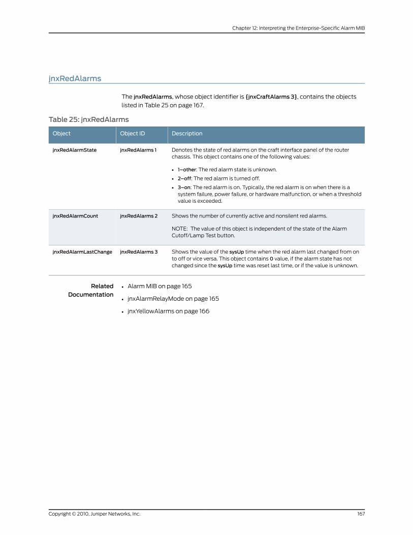
jnxRedAlarms
The jnxRedAlarms, whose object identifier is {jnxCraftAlarms 3}, contains the objects
listed in Table 25 on page 167.
Table 25: jnxRedAlarms
DescriptionObject IDObject
Denotes the state of red alarms on the craft interface panel of the routerchassis. This object contains one of the following values:
• 1–other: The red alarm state is unknown.
• 2–off: The red alarm is turned off.
• 3–on: The red alarm is on. Typically, the red alarm is on when there is asystem failure, power failure, or hardware malfunction, or when a thresholdvalue is exceeded.
jnxRedAlarms 1jnxRedAlarmState
Shows the number of currently active and nonsilent red alarms.
NOTE: The value of this object is independent of the state of the AlarmCutoff/Lamp Test button.
jnxRedAlarms 2jnxRedAlarmCount
Shows the value of the sysUp time when the red alarm last changed from onto off or vice versa. This object contains 0 value, if the alarm state has notchanged since the sysUp time was reset last time, or if the value is unknown.
jnxRedAlarms 3jnxRedAlarmLastChange
RelatedDocumentation
• Alarm MIB on page 165
• jnxAlarmRelayMode on page 165
• jnxYellowAlarms on page 166
167Copyright © 2010, Juniper Networks, Inc.
Chapter 12: Interpreting the Enterprise-Specific Alarm MIB

Copyright © 2010, Juniper Networks, Inc.168
SRX100, SRX210, SRX220, SRX240, and SRX650 Services Gateways MIB Reference

CHAPTER 13
Interpreting the Enterprise-Specific BGP4V2 MIB
• BGP4 V2 MIB on page 169
• jnxBgpM2PrefixCountersTable on page 170
BGP4 V2MIB
The Juniper Networks enterprise-specific BGP version 4 (BGP4) V2 MIB, whose object
identifier is {jnxBgpM2Experiment 1}, contains objects used to monitor BGP peer-received
prefix counters. It is based upon similar objects in the MIB documented in Internet draft
draft-ietf-idr-bgp4-mibv2-03.txt, Definitions of Managed Objects for the Fourth Version
of Border Gateway Protocol (BGP-4), Second Version. For a downloadable version of this
MIB, see
http://www.juniper.net/techpubs/en_US/junos10.4/topics/reference/mibs/mib-jnx-bgpmib2.txt
.
NOTE:
For the BGP4 V2MIB, Junos OS supports only the following objects:
• jnxBgpM2PrefixInPrefixes
• jnxBgpM2PrefixInPrefixesAccepted
• jnxBgpM2PrefixInPrefixesRejected
For information about the enterprise-specific BGP4 V2 MIB objects, see the following
topic:
• jnxBgpM2PrefixCountersTable on page 170
• Juniper Networks Enterprise-Specific BGP Traps on page 87
RelatedDocumentation
Juniper Networks Enterprise-Specific MIBs on page 23•
• Standard SNMP MIBs Supported by Junos OS on page 12
169Copyright © 2010, Juniper Networks, Inc.
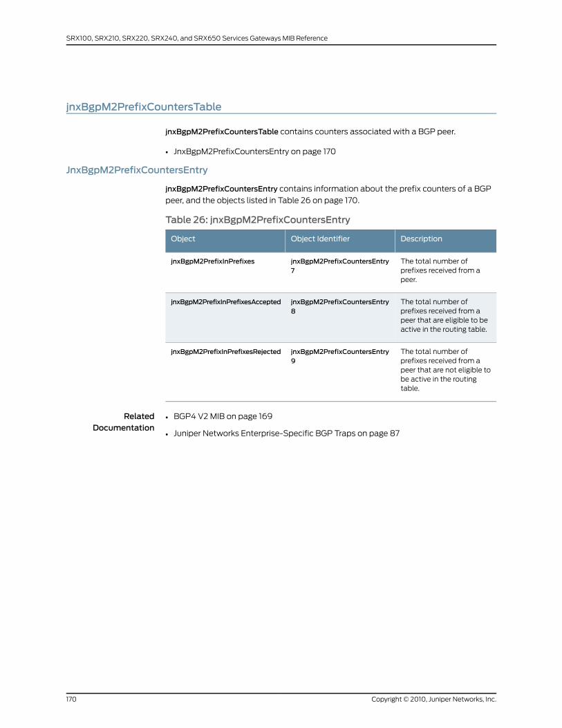
jnxBgpM2PrefixCountersTable
jnxBgpM2PrefixCountersTable contains counters associated with a BGP peer.
• JnxBgpM2PrefixCountersEntry on page 170
JnxBgpM2PrefixCountersEntry
jnxBgpM2PrefixCountersEntry contains information about the prefix counters of a BGP
peer, and the objects listed in Table 26 on page 170.
Table 26: jnxBgpM2PrefixCountersEntry
DescriptionObject IdentifierObject
The total number ofprefixes received from apeer.
jnxBgpM2PrefixCountersEntry7
jnxBgpM2PrefixInPrefixes
The total number ofprefixes received from apeer that are eligible to beactive in the routing table.
jnxBgpM2PrefixCountersEntry8
jnxBgpM2PrefixInPrefixesAccepted
The total number ofprefixes received from apeer that are not eligible tobe active in the routingtable.
jnxBgpM2PrefixCountersEntry9
jnxBgpM2PrefixInPrefixesRejected
RelatedDocumentation
• BGP4 V2 MIB on page 169
• Juniper Networks Enterprise-Specific BGP Traps on page 87
Copyright © 2010, Juniper Networks, Inc.170
SRX100, SRX210, SRX220, SRX240, and SRX650 Services Gateways MIB Reference
CHAPTER 14
Interpreting the Enterprise-SpecificBidirectional Forwarding Detection(BFD) MIB
• Bidirectional Forwarding Detection (BFD) MIB on page 171
• jnxBfdSessTable on page 171
• Notifications for the BFD MIB on page 172
Bidirectional Forwarding Detection (BFD)MIB
The Juniper Networks enterprise-specific Bidirectional Forwarding Detection (BFD) MIB,
whose object identifier is {jnxBfdMibRoot 1}, sends the current operational status for the
transmit interval and detection time of BFD sessions. For a downloadable version of this
MIB, see
http://www.juniper.net/techpubs/en_US/junos10.4/topics/reference/mibs/mib-jnx-bfd.txt
.
For information about the enterprise-specific BFD MIB objects, see the following topics:
• jnxBfdSessTable on page 171
• Notifications for the BFD MIB on page 172
RelatedDocumentation
Juniper Networks Enterprise-Specific MIBs on page 23•
• Standard SNMP MIBs Supported by Junos OS on page 12
jnxBfdSessTable
The jnxBfdSessTable, whose object identifier is {jnxBfdObjects 1}, is an extension to the
jnxSessTable. It provides information about threshold values for the transmit interval
and detection time on BFD sessions.
The jnxBfdSessEntry, whose object identifier is {jnxBfdSessTable 1}, has four objects,
which are listed in Table 27 on page 172.
171Copyright © 2010, Juniper Networks, Inc.
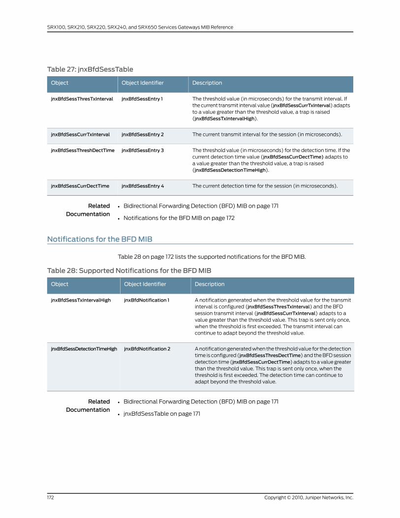
Table 27: jnxBfdSessTable
DescriptionObject IdentifierObject
The threshold value (in microseconds) for the transmit interval. Ifthe current transmit interval value (jnxBfdSessCurrTxInterval) adaptsto a value greater than the threshold value, a trap is raised(jnxBfdSessTxIntervalHigh).
jnxBfdSessEntry 1jnxBfdSessThresTxInterval
The current transmit interval for the session (in microseconds).jnxBfdSessEntry 2jnxBfdSessCurrTxInterval
The threshold value (in microseconds) for the detection time. If thecurrent detection time value (jnxBfdSessCurrDectTime) adapts toa value greater than the threshold value, a trap is raised(jnxBfdSessDetectionTimeHigh).
jnxBfdSessEntry 3jnxBfdSessThreshDectTime
The current detection time for the session (in microseconds).jnxBfdSessEntry 4jnxBfdSessCurrDectTime
RelatedDocumentation
Bidirectional Forwarding Detection (BFD) MIB on page 171•
• Notifications for the BFD MIB on page 172
Notifications for the BFDMIB
Table 28 on page 172 lists the supported notifications for the BFD MIB.
Table 28: Supported Notifications for the BFDMIB
DescriptionObject IdentifierObject
A notification generated when the threshold value for the transmitinterval is configured (jnxBfdSessThresTxInterval) and the BFDsession transmit interval (jnxBfdSessCurrTxInterval) adapts to avalue greater than the threshold value. This trap is sent only once,when the threshold is first exceeded. The transmit interval cancontinue to adapt beyond the threshold value.
jnxBfdNotification 1jnxBfdSessTxIntervalHigh
A notification generated when the threshold value for the detectiontime is configured (jnxBfdSessThresDectTime) and the BFD sessiondetection time (jnxBfdSessCurrDectTime) adapts to a value greaterthan the threshold value. This trap is sent only once, when thethreshold is first exceeded. The detection time can continue toadapt beyond the threshold value.
jnxBfdNotification 2jnxBfdSessDetectionTimeHigh
RelatedDocumentation
• Bidirectional Forwarding Detection (BFD) MIB on page 171
• jnxBfdSessTable on page 171
Copyright © 2010, Juniper Networks, Inc.172
SRX100, SRX210, SRX220, SRX240, and SRX650 Services Gateways MIB Reference
CHAPTER 15
Interpreting the Enterprise-SpecificChassis MIBs
• Chassis MIBs on page 173
• Textual Convention for Chassis MIB on page 174
• jnxBoxAnatomy on page 175
• Chassis Traps on page 260
• Chassis Definitions for Router Model MIB on page 265
• MIB Objects for the SRX100 Services Gateway on page 265
• MIB Objects for the SRX210 Services Gateway on page 266
• MIB Objects for the SRX220 Services Gateway on page 267
• MIB Objects for the SRX240 Services Gateway on page 267
• MIB Objects for the SRX650 Services Gateway on page 268
Chassis MIBs
The enterprise-specific Chassis MIB provides information on the router and its
components. MIB objects represent each component and the status of the components.
The enterprise-specific Chassis Definitions for Router Model MIB contains the object
identifiers (OIDs) that are used by the Chassis MIB to identify platform and chassis
components. The Chassis MIB provides information that changes often. The Chassis
Definitions for Router Model MIB provides information that changes less often.
You can retrieve information from the MIB using any network management system. For
a downloadable version of the Chassis Definitions for Router Model MIB, see
http://www.juniper.net/techpubs/en_US/junos10.4/information-products/topic-collections/reference-mibs-and-traps/mib-jnx-chas-defines.txt
.
For more information about the enterprise-specific Chassis MIBs, see the following topics:
• Textual Convention for Chassis MIB on page 174
• jnxBoxAnatomy on page 175
• Chassis Traps on page 260
• Chassis Definitions for Router Model MIB on page 265
173Copyright © 2010, Juniper Networks, Inc.
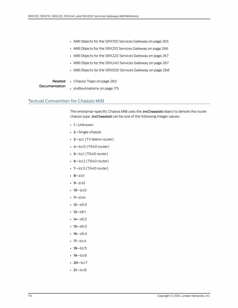
• MIB Objects for the SRX100 Services Gateway on page 265
• MIB Objects for the SRX210 Services Gateway on page 266
• MIB Objects for the SRX220 Services Gateway on page 267
• MIB Objects for the SRX240 Services Gateway on page 267
• MIB Objects for the SRX650 Services Gateway on page 268
RelatedDocumentation
Chassis Traps on page 260•
• jnxBoxAnatomy on page 175
Textual Convention for Chassis MIB
The enterprise-specific Chassis MIB uses the JnxChassisId object to denote the router
chassis type. JnxChassisId can be one of the following integer values:
• 1—Unknown
• 2—Single chassis
• 3—scc (TX Matrix router)
• 4—lcc0 (T640 router)
• 5—lcc1 (T640 router)
• 6—lcc2 (T640 router)
• 7—lcc3 (T640 router)
• 8—jcs1
• 9—jcs2
• 10—jcs3
• 11—jcs4
• 12—sfc0
• 13—sfc1
• 14—sfc2
• 15—sfc3
• 16—sfc4
• 17—lcc4
• 18—lcc5
• 19—lcc6
• 20—lcc7
• 21—lcc8
Copyright © 2010, Juniper Networks, Inc.174
SRX100, SRX210, SRX220, SRX240, and SRX650 Services Gateways MIB Reference
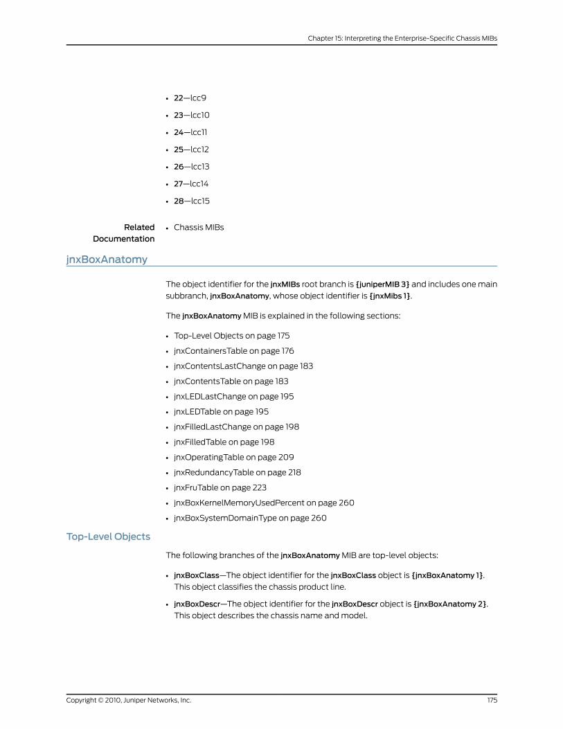
• 22—lcc9
• 23—lcc10
• 24—lcc11
• 25—lcc12
• 26—lcc13
• 27—lcc14
• 28—lcc15
RelatedDocumentation
Chassis MIBs•
jnxBoxAnatomy
The object identifier for the jnxMIBs root branch is {juniperMIB 3} and includes one main
subbranch, jnxBoxAnatomy, whose object identifier is {jnxMibs 1}.
The jnxBoxAnatomy MIB is explained in the following sections:
• Top-Level Objects on page 175
• jnxContainersTable on page 176
• jnxContentsLastChange on page 183
• jnxContentsTable on page 183
• jnxLEDLastChange on page 195
• jnxLEDTable on page 195
• jnxFilledLastChange on page 198
• jnxFilledTable on page 198
• jnxOperatingTable on page 209
• jnxRedundancyTable on page 218
• jnxFruTable on page 223
• jnxBoxKernelMemoryUsedPercent on page 260
• jnxBoxSystemDomainType on page 260
Top-Level Objects
The following branches of the jnxBoxAnatomy MIB are top-level objects:
• jnxBoxClass—The object identifier for the jnxBoxClass object is {jnxBoxAnatomy 1}.
This object classifies the chassis product line.
• jnxBoxDescr—The object identifier for the jnxBoxDescr object is {jnxBoxAnatomy 2}.
This object describes the chassis name and model.
175Copyright © 2010, Juniper Networks, Inc.
Chapter 15: Interpreting the Enterprise-Specific Chassis MIBs
• jnxBoxSerialNo—The object identifier for the jnxBoxSerialNo object is {jnxBoxAnatomy
3}. This object indicates the serial number of the chassis. jnxBoxSerialNo remains blank
if the serial number is unknown or unavailable.
• jnxBoxRevision—The object identifier for the jnxBoxRevision object is {jnxBoxAnatomy
4}. This object indicates the last revision of the chassis.
• jnxBoxInstalled—The object identifier for the jnxBoxInstalled object is {jnxBoxAnatomy
5}. This object indicates the last time the box was installed and operational, represented
by the sysUpTime value.
jnxContainersTable
The object identifier for the jnxContainersTable object is {jnxBoxAnatomy 6}. This object
shows the structure of the chassis.
You can use the jnxContainersTable object to retrieve specific information about the
router, such as how many of each component the router can contain. For example, the
jnxContainersTable object of an M20 router indicates that the router can accommodate
four Flexible PIC Concentrators (FPCs); however, it does not describe how many FPCs
the router actually has.
For more information about how many FPCs are actually on a router, see
“jnxContentsTable” on page 183.
Entries within the jnxContainersTable object are represented by the jnxContainersEntry
object, whose object identifier is {jnxContainersTable 1}. The jnxContainersEntry object
contains the following objects that describe the contents of a particular router:
• jnxContainersIndex—The index value of an entry in the jnxContainersEntry object that
corresponds to jnxContainersTypeand jnxContainersDescr, and whose object identifier
is {jnxContainersEntry 1}.
• jnxContainersView—The orientation of a container from the front of the router and
whose object identifier is {jnxContainersEntry 2}. This object also indicates that the
container is embedded in the router and how it is accessible from corresponding views.
The value of this object is a bitmap represented as a sum. If multiple bits are set, you
can access the container from that set of views. The values represent the bit positions
and their corresponding views as follows:
• 1—Front
• 2—Rear
• 4—Top
• 8—Bottom
• 16—Left side
• 32—Right side
Copyright © 2010, Juniper Networks, Inc.176
SRX100, SRX210, SRX220, SRX240, and SRX650 Services Gateways MIB Reference
For each view plane, if specified counters are scattered in various views, the numbering
sequence starts from left to right and then from top to bottom, as follows:
• Left side
• Right side
• Top
• Bottom
• Front
• Rear
NOTE: References to left and right sides are based on the view from thefront of the chassis.
In accordancewith networkmanagement conventions, all indexes in theMIB begin with 1, not 0, although the slot number might be labeled 0.
• jnxContainersLevel—The abstraction level of the box or components for the
jnxContainersEntry object and whose object identifier is {jnxContainersEntry 3}. The
level is enumerated from the outside to the inside, and from the outer layer to the inner
layer.
For example, if the top level (level 0) of the box refers to the chassis frame, then the
next level (level 1) refers to the FPC slot within the chassis frame. Finally, the PIC space
within the FPC slot of the chassis corresponds to level 2.
• jnxContainersWithin—The container housing the entry at the next-higher level of the
jnxContainersEntry object and whose object identifier is {jnxContainersEntry 4}.
For example, the within value for jnxMediaCardSpacePIC.0 is 7. Because the
jnxM20SlotFPC.0 retains an index value of 7, the FPC houses the PIC.
• jnxContainersType—The component of the Chassis MIB at a specific index, view, level,
and within value for the jnxContainersEntry object and whose object identifier is
{jnxContainersEntry 5}.
• jnxContainersDescr—The description of the component in the jnxContainersEntryobject
and whose object identifier is {jnxContainersEntry 6}.
• jnxContainersCount—The maximum number of a given component that the router can
accommodate within the jnxContainersEntry object and whose object identifier is
{jnxContainersEntry 7}.
For example, the M20 router can house a specific maximum number of FPCs within
the chassis frame. The maximum number is not necessarily the actual number of FPCs;
this can change dynamically.
177Copyright © 2010, Juniper Networks, Inc.
Chapter 15: Interpreting the Enterprise-Specific Chassis MIBs
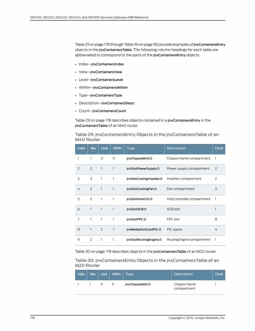
Table 29 on page 178 through Table 36 on page 182 provide examples of jnxContainersEntry
objects in the jnxContainersTable. The following column headings for each table are
abbreviated to correspond to the parts of the jnxContainersEntry objects:
• Index—jnxContainersIndex
• View—jnxContainersView
• Level—jnxContainersLevel
• Within—jnxContainersWithin
• Type—jnxContainersType
• Description—jnxContainersDescr
• Count—jnxContainersCount
Table 29 on page 178 describes objects contained in a jnxContainersEntry in the
jnxContainersTable of an M40 router.
Table 29: jnxContainersEntry Objects in the jnxContainersTable of anM40 Router
CountDescriptionTypeWithinLevelViewIndex
1Chassis frame compartmentjnxChassisM40.00011
2Power supply compartmentjnxSlotPowerSupply.01122
2Impeller compartmentjnxSlotCoolingImpeller.01133
3Fan compartmentjnxSlotCoolingFan.01124
1Host controller compartmentjnxSlotHostCtrl.01125
1SCB slotjnxSlotSCB.01116
8FPC slotjnxSlotFPC.01117
4PIC spacejnxMediaSlotCardPIC.07218
1Routing Engine compartmentjnxSlotRoutingEngine.01129
Table 30 on page 178 describes objects in the jnxContainersTable of an M20 router.
Table 30: jnxContainersEntry Objects in the jnxContainersTable of anM20 Router
CountDescriptionTypeWithinLevelViewIndex
1Chassis framecompartment
jnxChassisM20.00011
Copyright © 2010, Juniper Networks, Inc.178
SRX100, SRX210, SRX220, SRX240, and SRX650 Services Gateways MIB Reference
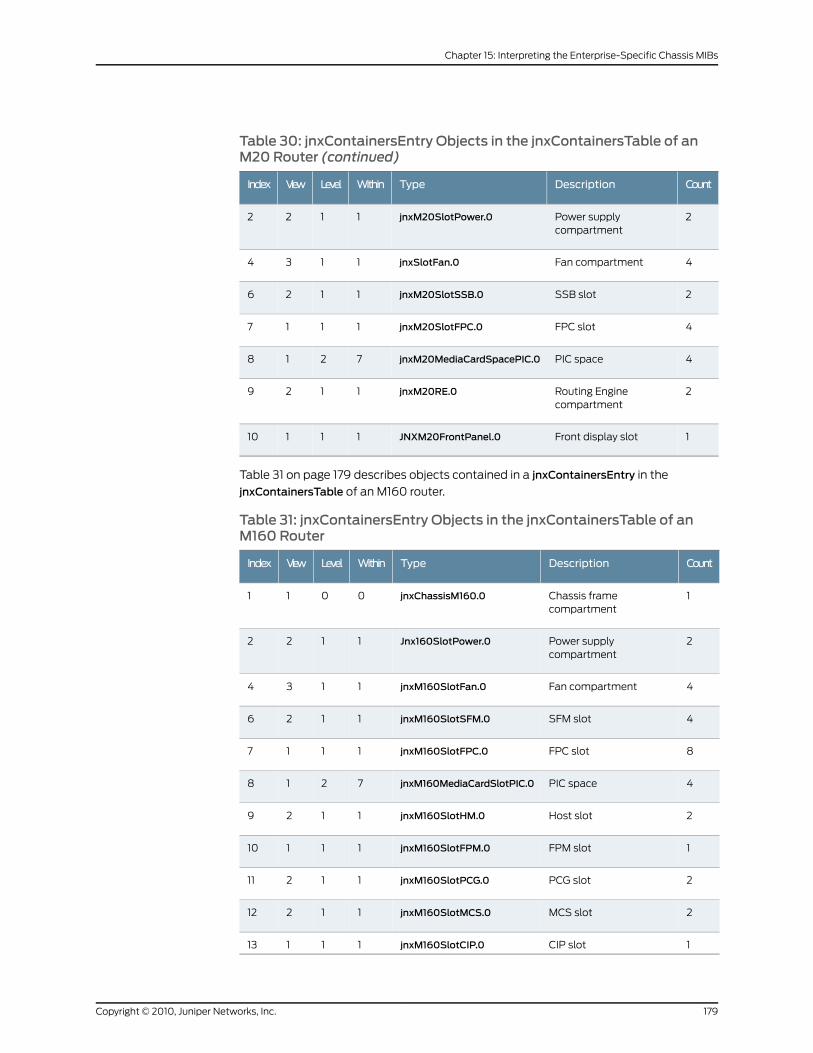
Table 30: jnxContainersEntry Objects in the jnxContainersTable of anM20 Router (continued)
CountDescriptionTypeWithinLevelViewIndex
2Power supplycompartment
jnxM20SlotPower.01122
4Fan compartmentjnxSlotFan.01134
2SSB slotjnxM20SlotSSB.01126
4FPC slotjnxM20SlotFPC.01117
4PIC spacejnxM20MediaCardSpacePIC.07218
2Routing Enginecompartment
jnxM20RE.01129
1Front display slotJNXM20FrontPanel.011110
Table 31 on page 179 describes objects contained in a jnxContainersEntry in the
jnxContainersTable of an M160 router.
Table 31: jnxContainersEntry Objects in the jnxContainersTable of anM160 Router
CountDescriptionTypeWithinLevelViewIndex
1Chassis framecompartment
jnxChassisM160.00011
2Power supplycompartment
Jnx160SlotPower.01122
4Fan compartmentjnxM160SlotFan.01134
4SFM slotjnxM160SlotSFM.01126
8FPC slotjnxM160SlotFPC.01117
4PIC spacejnxM160MediaCardSlotPIC.07218
2Host slotjnxM160SlotHM.01129
1FPM slotjnxM160SlotFPM.011110
2PCG slotjnxM160SlotPCG.011211
2MCS slotjnxM160SlotMCS.011212
1CIP slotjnxM160SlotCIP.011113
179Copyright © 2010, Juniper Networks, Inc.
Chapter 15: Interpreting the Enterprise-Specific Chassis MIBs
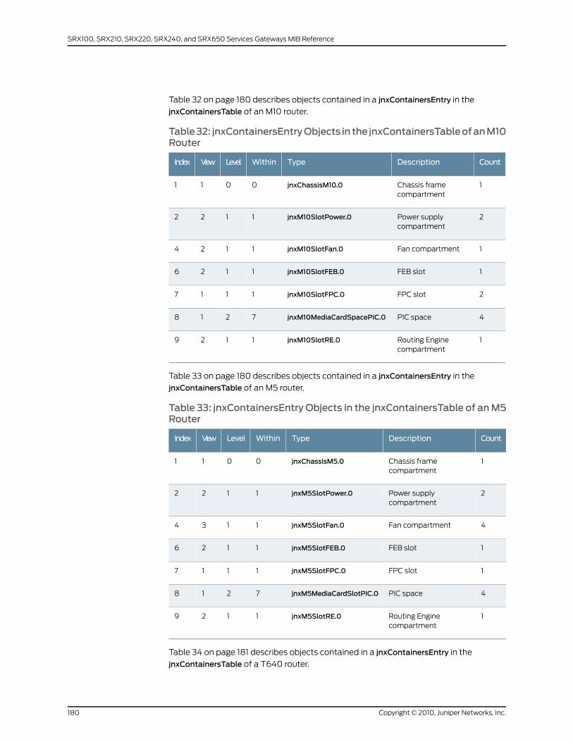
Table 32 on page 180 describes objects contained in a jnxContainersEntry in the
jnxContainersTable of an M10 router.
Table32: jnxContainersEntryObjects in the jnxContainersTableofanM10Router
CountDescriptionTypeWithinLevelViewIndex
1Chassis framecompartment
jnxChassisM10.00011
2Power supplycompartment
jnxM10SlotPower.01122
1Fan compartmentjnxM10SlotFan.01124
1FEB slotjnxM10SlotFEB.01126
2FPC slotjnxM10SlotFPC.01117
4PIC spacejnxM10MediaCardSpacePIC.07218
1Routing Enginecompartment
jnxM10SlotRE.01129
Table 33 on page 180 describes objects contained in a jnxContainersEntry in the
jnxContainersTable of an M5 router.
Table 33: jnxContainersEntry Objects in the jnxContainersTable of anM5Router
CountDescriptionTypeWithinLevelViewIndex
1Chassis framecompartment
jnxChassisM5.00011
2Power supplycompartment
jnxM5SlotPower.01122
4Fan compartmentjnxM5SlotFan.01134
1FEB slotjnxM5SlotFEB.01126
1FPC slotjnxM5SlotFPC.01117
4PIC spacejnxM5MediaCardSlotPIC.07218
1Routing Enginecompartment
jnxM5SlotRE.01129
Table 34 on page 181 describes objects contained in a jnxContainersEntry in the
jnxContainersTable of a T640 router.
Copyright © 2010, Juniper Networks, Inc.180
SRX100, SRX210, SRX220, SRX240, and SRX650 Services Gateways MIB Reference
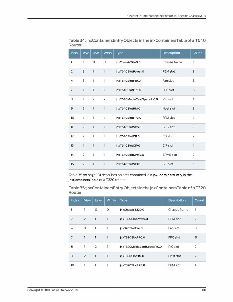
Table34: jnxContainersEntryObjects in the jnxContainersTableofaT640Router
CountDescriptionTypeWithinLevelViewIndex
1Chassis framejnxChassisT640.00011
2PEM slotjnxT640SlotPower.01122
3Fan slotjnxT640SlotFan.01134
8FPC slotjnxT640SlotFPC.01117
4PIC slotjnxT640MediaCardSpacePIC.07218
2Host slotjnxT640SlotHM.01129
1FPM slotjnxT640SlotFPB.011110
2SCG slotjnxT640SlotSCG.011211
2CG slotjnxT640SlotCB.011212
1CIP slotjnxT640SlotCIP.011113
2SPMB slotjnxT640SlotSPMB.011214
5SIB slotjnxT640SlotSIB.011215
Table 35 on page 181 describes objects contained in a jnxContainersEntry in the
jnxContainersTable of a T320 router.
Table35: jnxContainersEntryObjects in the jnxContainersTableofaT320Router
CountDescriptionTypeWithinLevelViewIndex
1Chassis framejnxChassisT320.00011
2PEM slotjnxT320SlotPower.01122
3Fan slotjnx320SlotFan.01134
8FPC slotjnxT320SlotFPC.01117
2PIC slotjnxT320MediaCardSpacePIC.07218
2Host slotjnxT320SlotHM.01129
1FPM slotjnxT320SlotFPB.011110
181Copyright © 2010, Juniper Networks, Inc.
Chapter 15: Interpreting the Enterprise-Specific Chassis MIBs
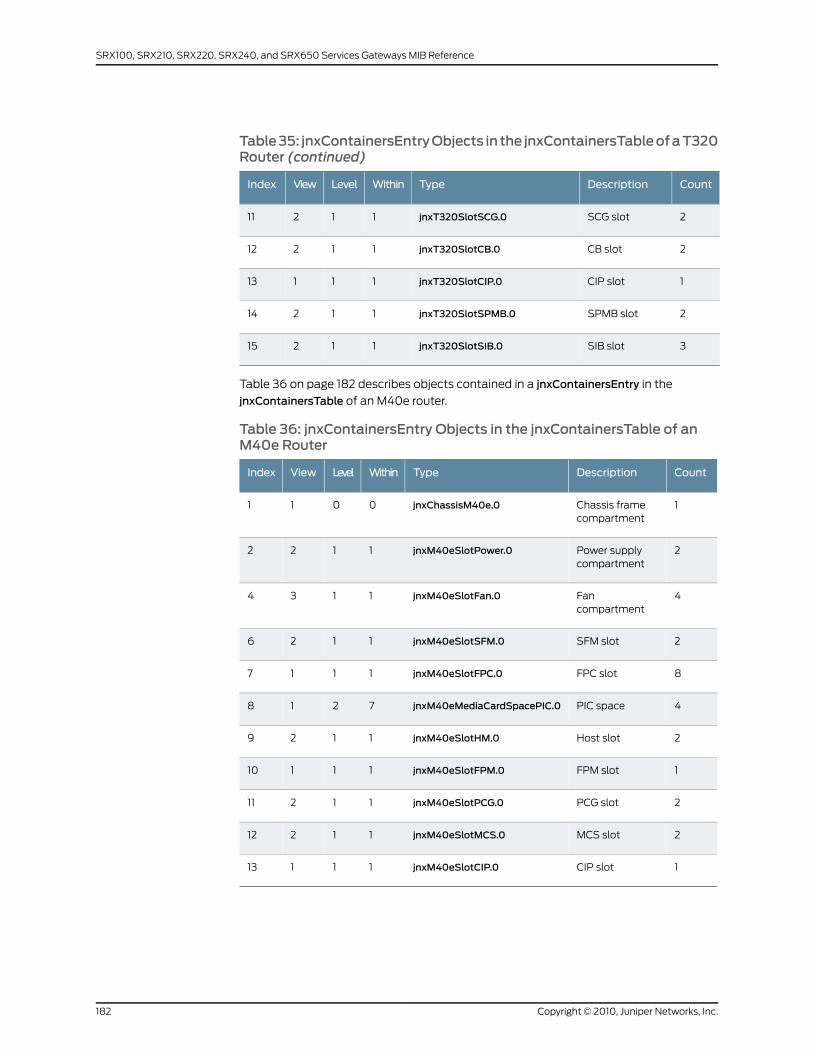
Table35: jnxContainersEntryObjects in the jnxContainersTableofaT320Router (continued)
CountDescriptionTypeWithinLevelViewIndex
2SCG slotjnxT320SlotSCG.011211
2CB slotjnxT320SlotCB.011212
1CIP slotjnxT320SlotCIP.011113
2SPMB slotjnxT320SlotSPMB.011214
3SIB slotjnxT320SlotSIB.011215
Table 36 on page 182 describes objects contained in a jnxContainersEntry in the
jnxContainersTable of an M40e router.
Table 36: jnxContainersEntry Objects in the jnxContainersTable of anM40e Router
CountDescriptionTypeWithinLevelViewIndex
1Chassis framecompartment
jnxChassisM40e.00011
2Power supplycompartment
jnxM40eSlotPower.01122
4Fancompartment
jnxM40eSlotFan.01134
2SFM slotjnxM40eSlotSFM.01126
8FPC slotjnxM40eSlotFPC.01117
4PIC spacejnxM40eMediaCardSpacePIC.07218
2Host slotjnxM40eSlotHM.01129
1FPM slotjnxM40eSlotFPM.011110
2PCG slotjnxM40eSlotPCG.011211
2MCS slotjnxM40eSlotMCS.011212
1CIP slotjnxM40eSlotCIP.011113
Copyright © 2010, Juniper Networks, Inc.182
SRX100, SRX210, SRX220, SRX240, and SRX650 Services Gateways MIB Reference
jnxContentsLastChange
The object identifier for jnxContentsLastChange object is {jnxBoxAnatomy 7}. This object
indicates the time at which the box contents last changed, represented by the sysUpTime
value.
jnxContentsTable
The object identifier for jnxContentsTable object is {jnxBoxAnatomy 8}. This object
specifies the contents of the chassis.
The jnxContentsTable lists the contents of an entry, which are defined as follows:
• jnxContentsContainerIndex—Associates the jnxContainersIndex with the
jnxContainersTable. The object identifier is {jnxContentsEntry 1}.
• jnxContentsL1Index—Denotes the level-one index of the container housing the
component. The object identifier is {jnxContentsEntry 2}. It indicates the position of
the component within different levels of the containers. This value is 0 if the position
is unavailable or not applicable.
NOTE: MIBsstartwithavalueof 1,whereas thephysical counton the routerstarts with a value of 0. To find the actual location of a component withina router, youmust subtract 1 from the L1, L2, or L3 index.
• jnxContentsL2Index—Denotes the level-two index of the container housing the
component. The object identifier is {jnxContentsEntry 3}. It indicates the position of
the component within different levels of the containers. This value is 0 if the position
is unavailable or not applicable.
• jnxContentsL3Index—Denotes the level-three index of the container housing the
component. The object identifier is {jnxContentsEntry 4}. It indicates the position of
the component within different levels of the containers. This value is 0 if the position
is unavailable or not applicable.
• jnxContentsType—Indicates the type of the component at a specific container index
or L1, L2, or L3 index. The object identifier is {jnxContentsEntry 5}.
• jnxContentsDescr—Specifies the type of the component in plain English. The object
identifier is {jnxContentsEntry 6}.
• jnxContentsSerialNo—Specfies the serial number of the component. The object identifier
is {jnxContentsEntry 7}.
• jnxContentsRevision—Contains the revision level of the component. The object identifier
is {jnxContentsEntry 8}.
• jnxContentsInstalled—Indicates the time at which the component was last installed
and operational, represented by the sysUpTime value. The object identifier is
{jnxContentsEntry 9}.
• jnxContentsPartNo—Contains the part number of the component (blank if unknown
or unavailable). The object identifier is {jnxContentsEntry 10}.
183Copyright © 2010, Juniper Networks, Inc.
Chapter 15: Interpreting the Enterprise-Specific Chassis MIBs
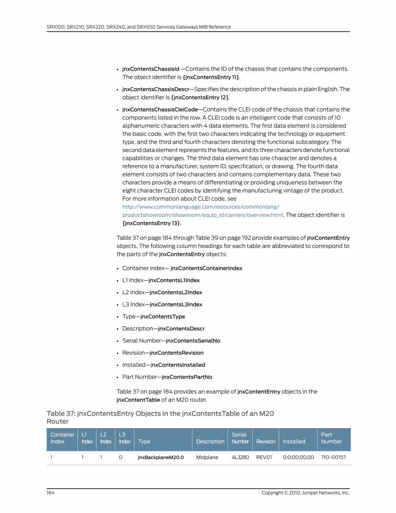
• jnxContentsChassisId—Contains the ID of the chassis that contains the components.
The object identifier is {jnxContentsEntry 11}.
• jnxContentsChassisDescr—Specifies the description of the chassis in plain English. The
object identifier is {jnxContentsEntry 12}.
• jnxContentsChassisCleiCode—Contains the CLEI code of the chassis that contains the
components listed in the row. A CLEI code is an intelligent code that consists of 10
alphanumeric characters with 4 data elements. The first data element is considered
the basic code, with the first two characters indicating the technology or equipment
type, and the third and fourth characters denoting the functional subcategory. The
second data element represents the features, and its three characters denote functional
capabilities or changes. The third data element has one character and denotes a
reference to a manufacturer, system ID, specification, or drawing. The fourth data
element consists of two characters and contains complementary data. These two
characters provide a means of differentiating or providing uniqueness between the
eight character CLEI codes by identifying the manufacturing vintage of the product.
For more information about CLEI code, see
http://www.commonlanguage.com/resources/commonlang/
productshowroom/showroom/equip_id/carriers/overview.html. The object identifier is
{jnxContentsEntry 13}.
Table 37 on page 184 through Table 39 on page 192 provide examples of jnxContentEntry
objects. The following column headings for each table are abbreviated to correspond to
the parts of the jnxContentsEntry objects:
• Container index— jnxContentsContainerIndex
• L1 Index—jnxContentsL1Index
• L2 Index—jnxContentsL2Index
• L3 Index—jnxContentsL3Index
• Type—jnxContentsType
• Description—jnxContentsDescr
• Serial Number—jnxContentsSerialNo
• Revision—jnxContentsRevision
• Installed—jnxContentsInstalled
• Part Number—jnxContentsPartNo
Table 37 on page 184 provides an example of jnxContentEntry objects in the
jnxContentTable of an M20 router.
Table 37: jnxContentsEntry Objects in the jnxContentsTable of anM20Router
PartNumberInstalledRevision
SerialNumberDescriptionType
L3Index
L2Index
L1Index
ContainerIndex
710-001570:0:00:00.00REV07AL3280MidplanejnxBackplaneM20.00111
Copyright © 2010, Juniper Networks, Inc.184
SRX100, SRX210, SRX220, SRX240, and SRX650 Services Gateways MIB Reference
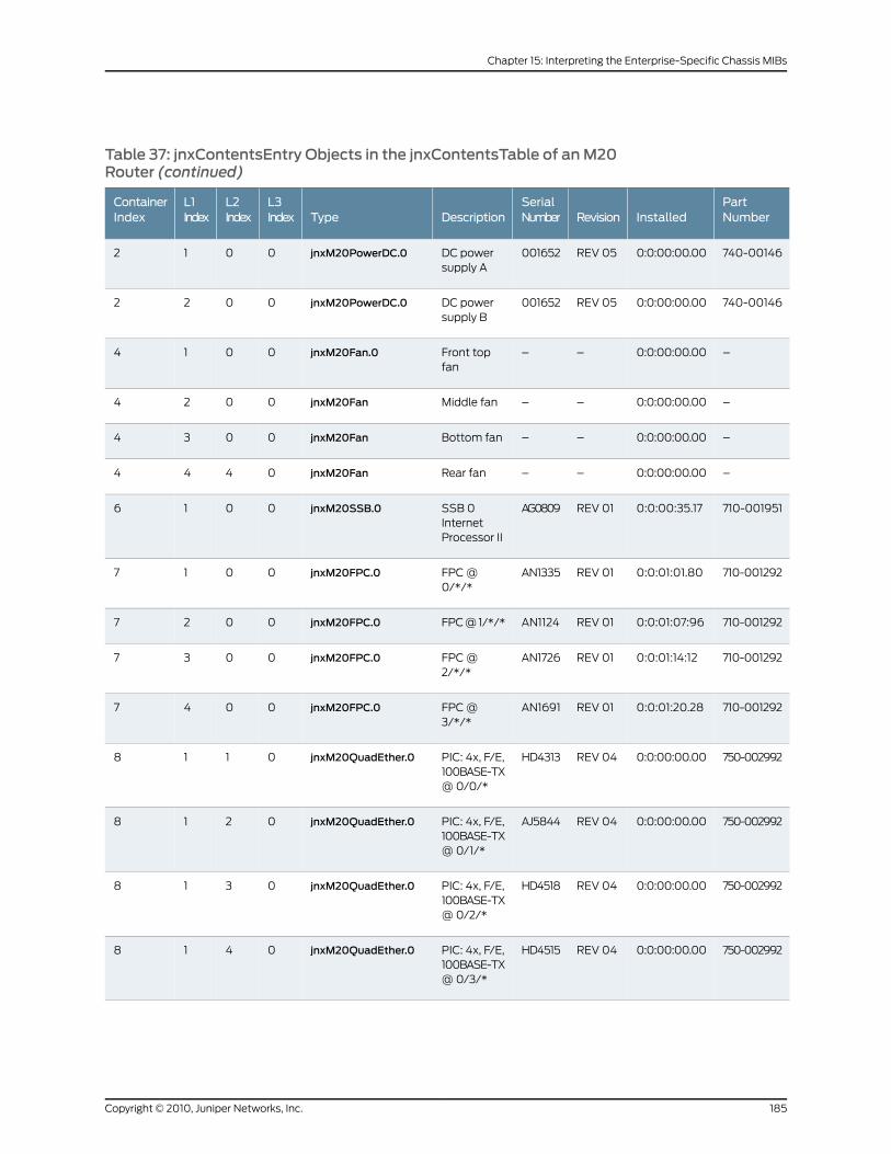
Table 37: jnxContentsEntry Objects in the jnxContentsTable of anM20Router (continued)
PartNumberInstalledRevision
SerialNumberDescriptionType
L3Index
L2Index
L1Index
ContainerIndex
740-001460:0:00:00.00REV 05001652DC powersupply A
jnxM20PowerDC.00012
740-001460:0:00:00.00REV 05001652DC powersupply B
jnxM20PowerDC.00022
–0:0:00:00.00––Front topfan
jnxM20Fan.00014
–0:0:00:00.00––Middle fanjnxM20Fan0024
–0:0:00:00.00––Bottom fanjnxM20Fan0034
–0:0:00:00.00––Rear fanjnxM20Fan0444
710-0019510:0:00:35.17REV 01AG0809SSB 0InternetProcessor II
jnxM20SSB.00016
710-0012920:0:01:01.80REV 01AN1335FPC @0/*/*
jnxM20FPC.00017
710-0012920:0:01:07:96REV 01AN1124FPC @ 1/*/*jnxM20FPC.00027
710-0012920:0:01:14:12REV 01AN1726FPC @2/*/*
jnxM20FPC.00037
710-0012920:0:01:20.28REV 01AN1691FPC @3/*/*
jnxM20FPC.00047
750-0029920:0:00:00.00REV 04HD4313PIC: 4x, F/E,100BASE-TX@ 0/0/*
jnxM20QuadEther.00118
750-0029920:0:00:00.00REV 04AJ5844PIC: 4x, F/E,100BASE-TX@ 0/1/*
jnxM20QuadEther.00218
750-0029920:0:00:00.00REV 04HD4518PIC: 4x, F/E,100BASE-TX@ 0/2/*
jnxM20QuadEther.00318
750-0029920:0:00:00.00REV 04HD4515PIC: 4x, F/E,100BASE-TX@ 0/3/*
jnxM20QuadEther.00418
185Copyright © 2010, Juniper Networks, Inc.
Chapter 15: Interpreting the Enterprise-Specific Chassis MIBs

Table 37: jnxContentsEntry Objects in the jnxContentsTable of anM20Router (continued)
PartNumberInstalledRevision
SerialNumberDescriptionType
L3Index
L2Index
L1Index
ContainerIndex
750-0029920:0:00:00.00REV 04HD4296PIC: 4x, F/E,100BASE-TX@ 1/0/*
jnxM20QuadEther.00128
750-0029920:0:00:00.00REV 04HD4323PIC: 4x, F/E,100BASE-TX@ 1/1/*
jnxM20QuadEther.00228
750-0029920:0:00:00.00REV 04HD4129PIC: 4x, F/E,100BASE-TX@ 1/2/*
jnxM20QuadEther.00328
750-0029920:0:00:00.00REV 04HD4341PIC: 4x, F/E,100BASE-TX@ 1/3/*
jnxM20QuadEther.00428
750-0023030:0:00:00.00REV 07AH4147PIC: 4x, F/E,100BASE-TX@2/0/*
jnxM20QuadEther.00138
750-0023030:0:00:00.00REV 07AH4238PIC: 4x, F/E,100BASE-TX@ 2/1/*
jnxM20QuadEther.00238
750-0023030:0:00:00.00REV 07AH4116PIC: 4x, F/E,100BASE-TX@ 2/2/*
jnxM20QuadEther.00338
750-0023030:0:00:00.00REV 07AH4208PIC: 4x, F/E,100BASE-TX@ 2/3/*
jnxM20QuadEther.00438
750-0010720:0:00:00.00REV 07AS3697PIC: 1x G/E,1000BASE-SX@ 3/0/*
jnxM20GigEther.00148
750-0011900:0:00:00.00REV 08AE1110PIC: 1xCOC12SMIR@ 3/1/*
jnxM20ChOc12toDS3.00248
750-0032500:0:00:00.00REV 04AD9599PIC: 1xCSTM1SMIR@ 3/3/*
jnxM20ChStml1.00448
–3:16:16:53.21––RoutingEngine
jnxM20RE.00019
–0:0:00:00.00––Front paneldisplay
jnxM20FrontPanel.000110
Copyright © 2010, Juniper Networks, Inc.186
SRX100, SRX210, SRX220, SRX240, and SRX650 Services Gateways MIB Reference
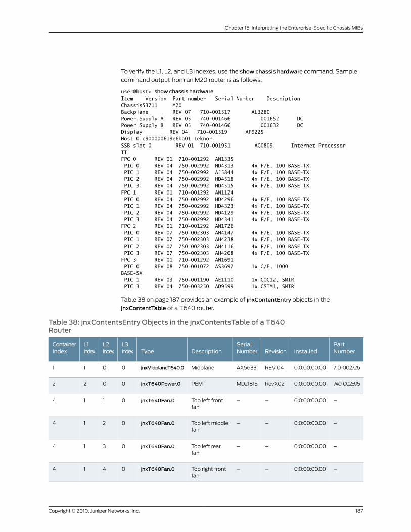
To verify the L1, L2, and L3 indexes, use the show chassis hardware command. Sample
command output from an M20 router is as follows:
user@host> show chassis hardwareItem Version Part number Serial Number DescriptionChassis53711 M20Backplane REV 07 710-001517 AL3280Power Supply A REV 05 740-001466 001652 DCPower Supply B REV 05 740-001466 001632 DCDisplay REV 04 710-001519 AP9225Host 0 c900000619e6ba01 teknorSSB slot 0 REV 01 710-001951 AG0809 Internet ProcessorIIFPC 0 REV 01 710-001292 AN1335 PIC 0 REV 04 750-002992 HD4313 4x F/E, 100 BASE-TX PIC 1 REV 04 750-002992 AJ5844 4x F/E, 100 BASE-TX PIC 2 REV 04 750-002992 HD4518 4x F/E, 100 BASE-TX PIC 3 REV 04 750-002992 HD4515 4x F/E, 100 BASE-TXFPC 1 REV 01 710-001292 AN1124 PIC 0 REV 04 750-002992 HD4296 4x F/E, 100 BASE-TX PIC 1 REV 04 750-002992 HD4323 4x F/E, 100 BASE-TX PIC 2 REV 04 750-002992 HD4129 4x F/E, 100 BASE-TX PIC 3 REV 04 750-002992 HD4341 4x F/E, 100 BASE-TXFPC 2 REV 01 710-001292 AN1726 PIC 0 REV 07 750-002303 AH4147 4x F/E, 100 BASE-TX PIC 1 REV 07 750-002303 AH4238 4x F/E, 100 BASE-TX PIC 2 REV 07 750-002303 AH4116 4x F/E, 100 BASE-TX PIC 3 REV 07 750-002303 AH4208 4x F/E, 100 BASE-TXFPC 3 REV 01 710-001292 AN1691 PIC 0 REV 08 750-001072 AS3697 1x G/E, 1000BASE-SX PIC 1 REV 03 750-001190 AE1110 1x COC12, SMIR PIC 3 REV 04 750-003250 AD9599 1x CSTM1, SMIR
Table 38 on page 187 provides an example of jnxContentEntry objects in the
jnxContentTable of a T640 router.
Table 38: jnxContentsEntry Objects in the jnxContentsTable of a T640Router
PartNumberInstalledRevision
SerialNumberDescriptionType
L3Index
L2Index
L1Index
ContainerIndex
710-0027260:0:00:00.00REV 04AX5633MidplanejnxMidplaneT640.00011
740-0025950:0:00:00.00RevX02MD21815PEM 1jnxT640Power.00022
–0:0:00:00.00––Top left frontfan
jnxT640Fan.00114
–0:0:00:00.00––Top left middlefan
jnxT640Fan.00214
–0:0:00:00.00––Top left rearfan
jnxT640Fan.00314
–0:0:00:00.00––Top right frontfan
jnxT640Fan.00414
187Copyright © 2010, Juniper Networks, Inc.
Chapter 15: Interpreting the Enterprise-Specific Chassis MIBs
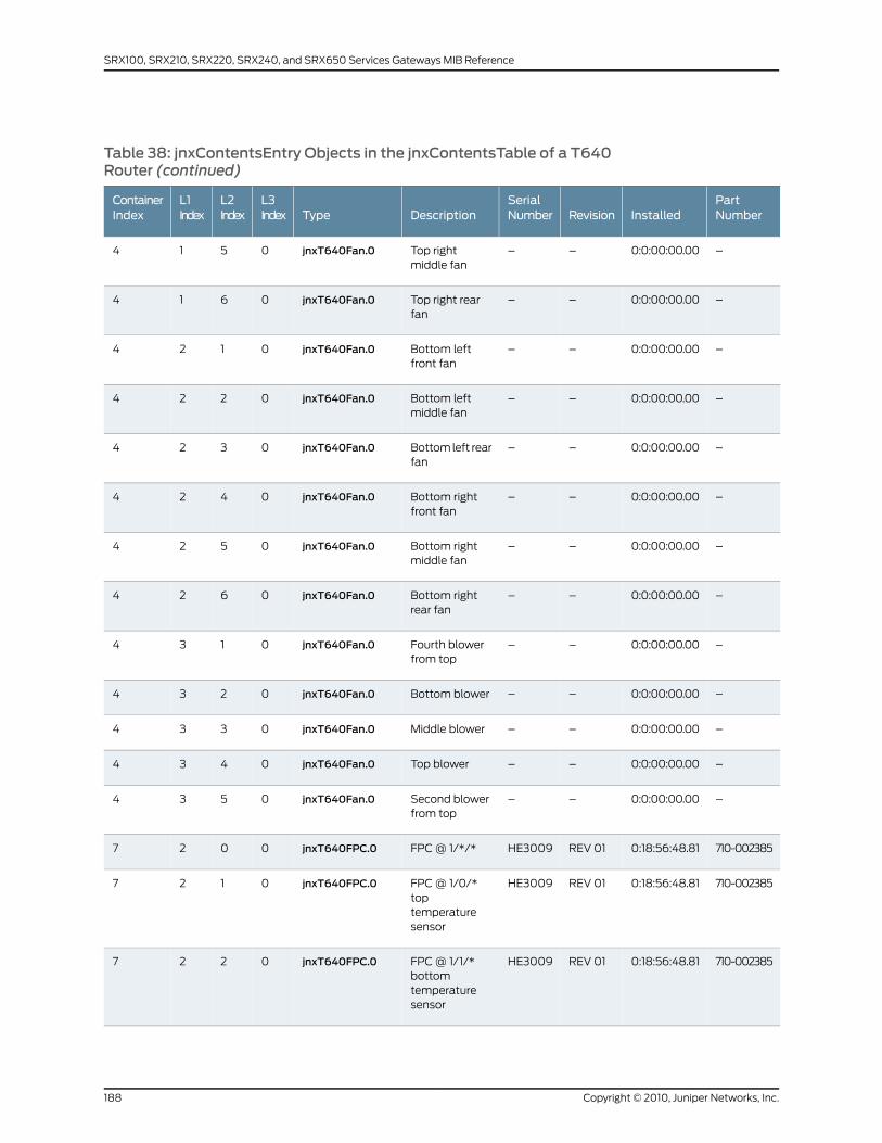
Table 38: jnxContentsEntry Objects in the jnxContentsTable of a T640Router (continued)
PartNumberInstalledRevision
SerialNumberDescriptionType
L3Index
L2Index
L1Index
ContainerIndex
–0:0:00:00.00––Top rightmiddle fan
jnxT640Fan.00514
–0:0:00:00.00––Top right rearfan
jnxT640Fan.00614
–0:0:00:00.00––Bottom leftfront fan
jnxT640Fan.00124
–0:0:00:00.00––Bottom leftmiddle fan
jnxT640Fan.00224
–0:0:00:00.00––Bottom left rearfan
jnxT640Fan.00324
–0:0:00:00.00––Bottom rightfront fan
jnxT640Fan.00424
–0:0:00:00.00––Bottom rightmiddle fan
jnxT640Fan.00524
–0:0:00:00.00––Bottom rightrear fan
jnxT640Fan.00624
–0:0:00:00.00––Fourth blowerfrom top
jnxT640Fan.00134
–0:0:00:00.00––Bottom blowerjnxT640Fan.00234
–0:0:00:00.00––Middle blowerjnxT640Fan.00334
–0:0:00:00.00––Top blowerjnxT640Fan.00434
–0:0:00:00.00––Second blowerfrom top
jnxT640Fan.00534
710-0023850:18:56:48.81REV 01HE3009FPC @ 1/*/*jnxT640FPC.00027
710-0023850:18:56:48.81REV 01HE3009FPC @ 1/0/*toptemperaturesensor
jnxT640FPC.00127
710-0023850:18:56:48.81REV 01HE3009FPC @ 1/1/*bottomtemperaturesensor
jnxT640FPC.00227
Copyright © 2010, Juniper Networks, Inc.188
SRX100, SRX210, SRX220, SRX240, and SRX650 Services Gateways MIB Reference
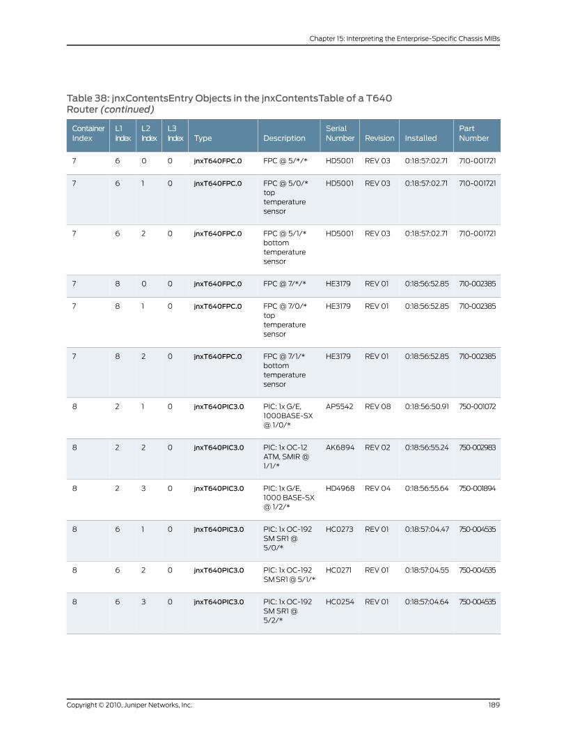
Table 38: jnxContentsEntry Objects in the jnxContentsTable of a T640Router (continued)
PartNumberInstalledRevision
SerialNumberDescriptionType
L3Index
L2Index
L1Index
ContainerIndex
710-0017210:18:57:02.71REV 03HD5001FPC @ 5/*/*jnxT640FPC.00067
710-0017210:18:57:02.71REV 03HD5001FPC @ 5/0/*toptemperaturesensor
jnxT640FPC.00167
710-0017210:18:57:02.71REV 03HD5001FPC @ 5/1/*bottomtemperaturesensor
jnxT640FPC.00267
710-0023850:18:56:52.85REV 01HE3179FPC @ 7/*/*jnxT640FPC.00087
710-0023850:18:56:52.85REV 01HE3179FPC @ 7/0/*toptemperaturesensor
jnxT640FPC.00187
710-0023850:18:56:52.85REV 01HE3179FPC @ 7/1/*bottomtemperaturesensor
jnxT640FPC.00287
750-0010720:18:56:50.91REV 08AP5542PIC: 1x G/E,1000BASE-SX@ 1/0/*
jnxT640PIC3.00128
750-0029830:18:56:55.24REV 02AK6894PIC: 1x OC-12ATM, SMIR @1/1/*
jnxT640PIC3.00228
750-0018940:18:56:55.64REV 04HD4968PIC: 1x G/E,1000 BASE-SX@ 1/2/*
jnxT640PIC3.00328
750-0045350:18:57:04.47REV 01HC0273PIC: 1x OC-192SM SR1 @5/0/*
jnxT640PIC3.00168
750-0045350:18:57:04.55REV 01HC0271PIC: 1x OC-192SM SR1 @ 5/1/*
jnxT640PIC3.00268
750-0045350:18:57:04.64REV 01HC0254PIC: 1x OC-192SM SR1 @5/2/*
jnxT640PIC3.00368
189Copyright © 2010, Juniper Networks, Inc.
Chapter 15: Interpreting the Enterprise-Specific Chassis MIBs
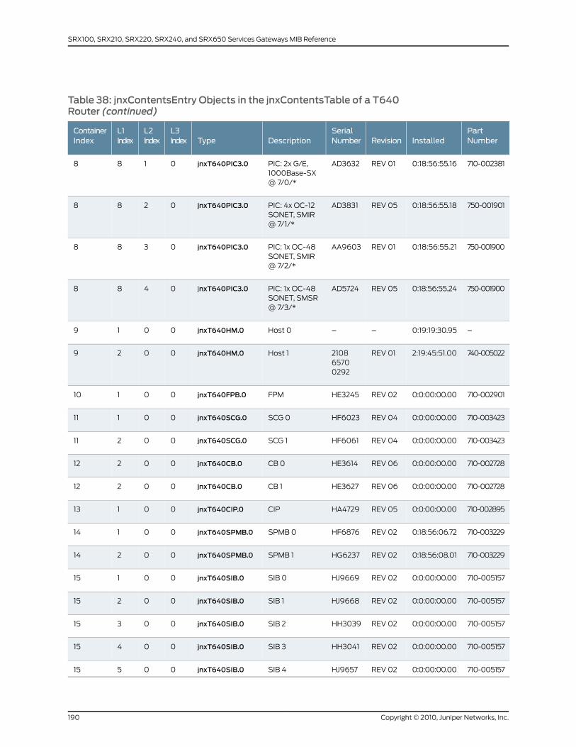
Table 38: jnxContentsEntry Objects in the jnxContentsTable of a T640Router (continued)
PartNumberInstalledRevision
SerialNumberDescriptionType
L3Index
L2Index
L1Index
ContainerIndex
710-0023810:18:56:55.16REV 01AD3632PIC: 2x G/E,1000Base-SX@ 7/0/*
jnxT640PIC3.00188
750-0019010:18:56:55.18REV 05AD3831PIC: 4x OC-12SONET, SMIR@ 7/1/*
jnxT640PIC3.00288
750-0019000:18:56:55.21REV 01AA9603PIC: 1x OC-48SONET, SMIR@ 7/2/*
jnxT640PIC3.00388
750-0019000:18:56:55.24REV 05AD5724PIC: 1x OC-48SONET, SMSR@ 7/3/*
jnxT640PIC3.00488
–0:19:19:30.95––Host 0jnxT640HM.00019
740-0050222:19:45:51.00REV 01210865700292
Host 1jnxT640HM.00029
710-0029010:0:00:00.00REV 02HE3245FPMjnxT640FPB.000110
710-0034230:0:00:00.00REV 04HF6023SCG 0jnxT640SCG.000111
710-0034230:0:00:00.00REV 04HF6061SCG 1jnxT640SCG.000211
710-0027280:0:00:00.00REV 06HE3614CB 0jnxT640CB.000212
710-0027280:0:00:00.00REV 06HE3627CB 1jnxT640CB.000212
710-0028950:0:00:00.00REV 05HA4729CIPjnxT640CIP.000113
710-0032290:18:56:06.72REV 02HF6876SPMB 0jnxT640SPMB.000114
710-0032290:18:56:08.01REV 02HG6237SPMB 1jnxT640SPMB.000214
710-0051570:0:00:00.00REV 02HJ9669SIB 0jnxT640SIB.000115
710-0051570:0:00:00.00REV 02HJ9668SIB 1jnxT640SIB.000215
710-0051570:0:00:00.00REV 02HH3039SIB 2jnxT640SIB.000315
710-0051570:0:00:00.00REV 02HH3041SIB 3jnxT640SIB.000415
710-0051570:0:00:00.00REV 02HJ9657SIB 4jnxT640SIB.000515
Copyright © 2010, Juniper Networks, Inc.190
SRX100, SRX210, SRX220, SRX240, and SRX650 Services Gateways MIB Reference
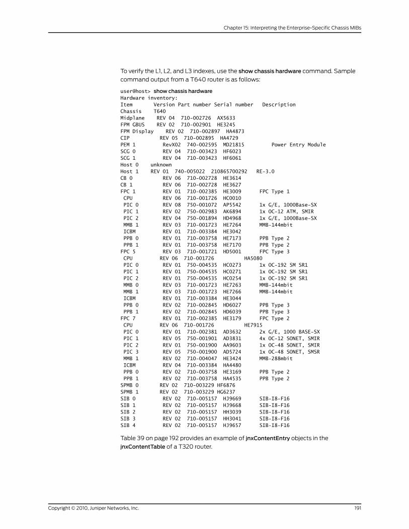
To verify the L1, L2, and L3 indexes, use the show chassis hardware command. Sample
command output from a T640 router is as follows:
user@host> show chassis hardwareHardware inventory:Item Version Part number Serial number DescriptionChassis T640Midplane REV 04 710-002726 AX5633FPM GBUS REV 02 710-002901 HE3245FPM Display REV 02 710-002897 HA4873CIP REV 05 710-002895 HA4729PEM 1 RevX02 740-002595 MD21815 Power Entry ModuleSCG 0 REV 04 710-003423 HF6023SCG 1 REV 04 710-003423 HF6061Host 0 unknownHost 1 REV 01 740-005022 210865700292 RE-3.0CB 0 REV 06 710-002728 HE3614CB 1 REV 06 710-002728 HE3627FPC 1 REV 01 710-002385 HE3009 FPC Type 1 CPU REV 06 710-001726 HC0010 PIC 0 REV 08 750-001072 AP5542 1x G/E, 1000Base-SX PIC 1 REV 02 750-002983 AK6894 1x OC-12 ATM, SMIR PIC 2 REV 04 750-001894 HD4968 1x G/E, 1000Base-SX MMB 1 REV 03 710-001723 HE7264 MMB-144mbit ICBM REV 01 710-003384 HE3042 PPB 0 REV 01 710-003758 HE7173 PPB Type 2 PPB 1 REV 01 710-003758 HE7170 PPB Type 2FPC 5 REV 03 710-001721 HD5001 FPC Type 3 CPU REV 06 710-001726 HA5080 PIC 0 REV 01 750-004535 HC0273 1x OC-192 SM SR1 PIC 1 REV 01 750-004535 HC0271 1x OC-192 SM SR1 PIC 2 REV 01 750-004535 HC0254 1x OC-192 SM SR1 MMB 0 REV 03 710-001723 HE7263 MMB-144mbit MMB 1 REV 03 710-001723 HE7266 MMB-144mbit ICBM REV 01 710-003384 HE3044 PPB 0 REV 02 710-002845 HD6027 PPB Type 3 PPB 1 REV 02 710-002845 HD6039 PPB Type 3FPC 7 REV 01 710-002385 HE3179 FPC Type 2 CPU REV 06 710-001726 HE7915 PIC 0 REV 01 710-002381 AD3632 2x G/E, 1000 BASE-SX PIC 1 REV 05 750-001901 AD3831 4x OC-12 SONET, SMIR PIC 2 REV 01 750-001900 AA9603 1x OC-48 SONET, SMIR PIC 3 REV 05 750-001900 AD5724 1x OC-48 SONET, SMSR MMB 1 REV 02 710-004047 HE3424 MMB-288mbit ICBM REV 04 710-003384 HA4480 PPB 0 REV 02 710-003758 HE3169 PPB Type 2 PPB 1 REV 02 710-003758 HA4535 PPB Type 2SPMB 0 REV 02 710-003229 HF6876SPMB 1 REV 02 710-003229 HG6237SIB 0 REV 02 710-005157 HJ9669 SIB-I8-F16SIB 1 REV 02 710-005157 HJ9668 SIB-I8-F16SIB 2 REV 02 710-005157 HH3039 SIB-I8-F16SIB 3 REV 02 710-005157 HH3041 SIB-I8-F16SIB 4 REV 02 710-005157 HJ9657 SIB-I8-F16
Table 39 on page 192 provides an example of jnxContentEntry objects in the
jnxContentTable of a T320 router.
191Copyright © 2010, Juniper Networks, Inc.
Chapter 15: Interpreting the Enterprise-Specific Chassis MIBs
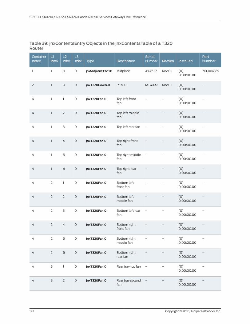
Table 39: jnxContentsEntry Objects in the jnxContentsTable of a T320Router
PartNumberInstalledRevision
SerialNumberDescriptionType
L3Index
L2Index
L1Index
ContainerIndex
710-004339(0)0:00:00.00
Rev 01AY4527MidplanejnxMidplaneT320.00011
–(0)0:00:00.00
Rev 01ML14099PEM 0jnxT320Power.00012
–(0)0:00:00.00
––Top left frontfan
jnxT320Fan.00114
–(0)0:00:00.00
––Top left middlefan
jnxT320Fan.00214
–(0)0:00:00.00
––Top left rear fanjnxT320Fan.00314
–(0)0:00:00.00
––Top right frontfan
jnxT320Fan.00414
–(0)0:00:00.00
––Top right middlefan
jnxT320Fan.00514
–(0)0:00:00.00
––Top right rearfan
jnxT320Fan.00614
–(0)0:00:00.00
––Bottom leftfront fan
jnxT320Fan.00124
–(0)0:00:00.00
––Bottom leftmiddle fan
jnxT320Fan.00224
–(0)0:00:00.00
––Bottom left rearfan
jnxT320Fan.00324
–(0)0:00:00.00
––Bottom rightfront fan
jnxT320Fan.00424
–(0)0:00:00.00
––Bottom rightmiddle fan
jnxT320Fan.00524
–(0)0:00:00.00
––Bottom rightrear fan
jnxT320Fan.00624
–(0)0:00:00.00
––Rear tray top fanjnxT320Fan.00134
–(0)0:00:00.00
––Rear tray secondfan
jnxT320Fan.00234
Copyright © 2010, Juniper Networks, Inc.192
SRX100, SRX210, SRX220, SRX240, and SRX650 Services Gateways MIB Reference

Table 39: jnxContentsEntry Objects in the jnxContentsTable of a T320Router (continued)
PartNumberInstalledRevision
SerialNumberDescriptionType
L3Index
L2Index
L1Index
ContainerIndex
–(0)0:00:00.00
––Rear tray middlefan
jnxT320Fan.00334
–(0)0:00:00.00
––Rear tray fourthfan
jnxT320Fan.00434
–(0)0:00:00.00
––Rear traybottom fan
jnxT320Fan.00534
710-004333(26190949)3 days,0:45:09.49
REV 01AY4706FPC @ 3/*/*jnxT320FPC.00047
710-004333(26190949)3 days,0:45:09.49
REV 01AY4706FPC @ 3/0/*top temperaturesensor
jnxT320FPC.00147
710-004333(26190949)3 days,0:45:09.49
REV 01AY4706FPC @ 3/1/*bottomtemperaturesensor
jnxT320FPC.00247
750-004535(6378)0:01:03.78
REV 06HJ9283PIC: 1x OC-192SM SR2 @0/0/*
jnxT320PIC30118
750-004535(6434)0:01:04.34
REV 06HJ9298PIC: 1x OC-192SM SR2 @ 0/1/*
jnxT320PIC30218
740-005022(32762924)3 days,19:00:29.24
REV 01210865700286
Host 0jnxT320HM.00019
740-005022(110269900)12 days,18:18:19.00
REV 01210929000186
Host 1jnxT320HM.00029
710-004461(0)0:00:00.00
REV 02AY4514FPMjnxT320FPB.000110
710-004455(0)0:00:00.00
REV 06AY4520SCG 0jnxT320SCG.000111
710-004455(0)0:00:00.00
REV 06AY4526SCG 1jnxT320SCG.000211
710-002728(0)0:00:00.00
REV 11AY4765CB 0jnxT320CB.000112
193Copyright © 2010, Juniper Networks, Inc.
Chapter 15: Interpreting the Enterprise-Specific Chassis MIBs

Table 39: jnxContentsEntry Objects in the jnxContentsTable of a T320Router (continued)
PartNumberInstalledRevision
SerialNumberDescriptionType
L3Index
L2Index
L1Index
ContainerIndex
710-002728(0)0:00:00.00
REV 06HG6051CB 1jnxT320CB.000212
710-002895(0)0:00:00.00
REV 05HC0476CIPjnxT320CIP.000113
710-003229(26186997)3 days,0:44:29.97
REV 02HB1893SPMB 0jnxT320SPMB.000114
710-003229(26186913) 3days,0:44:29.13
REV 02HD5520SPMB 1jnxT320SPMB.000214
710-005157(0)0:00:00.00
REV 02BC1509SIB 0jnxT320SIB.000115
710-005157(0)0:00:00.00
REV 02BC1512SIB 1jnxT320SIB.000215
710-005157(0)0:00:00.00
REV 02BC1494SIB 2jnxT320SIB.000315
To verify the L1, L2, and L3 indexes, use the show chassis hardware command. Sample
command output from a T320 router is as follows:
user@host> show chassis hardwareHardware inventory:Item Version Part number Serial number DescriptionChassis T320Midplane REV 01 710-004339 AY4527FPM GBUS REV 02 710-004461 AY4514FPM Display REV 02 710-002897 HF6097CIP REV 05 710-002895 HC0476PEM 0 Rev 01 740-004359 ML14099 Power EntryModuleSCG 0 REV 06 710-004455 AY4520SCG 1 REV 06 710-004455 AY4526RE 0 REV 01 740-005022 210865700286 RE-3.0RE 1 REV 01 740-005022 210929000186 RE-3.0CB 0 REV 11 710-002728 AY4765CB 1 REV 06 710-002728 HG6051FPC 1 REV 01 710-004333 AY4507 FPC Type 3 CPU REV 06 710-001726 HA4719 MMB 1 REV 03 710-004047 HD5738 MMB-288mbit PPB 0 REV 02 710-002845 HC0988 PPB Type 3FPC 3 REV 01 710-004333 AY4706 FPC Type 3 CPU REV 06 710-001726 HE7916 MMB 1 REV 03 710-004047 HG6326 MMB-288mbit PPB 0 REV 02 710-002845 HC0958 PPB Type 3SPMB 0 REV 02 710-003229 HB1893
Copyright © 2010, Juniper Networks, Inc.194
SRX100, SRX210, SRX220, SRX240, and SRX650 Services Gateways MIB Reference
SPMB 1 REV 02 710-003229 HD5520SIB 0 REV 02 710-005157 BC1509 SIB-I8-F16SIB 1 REV 02 710-005157 BC1512 SIB-I8-F16SIB 2 REV 02 710-005157 BC1494 SIB-I8-F16
jnxLEDLastChange
The object identifier for the jnxLEDLastChange object is {jnxBoxAnatomy 9}. This object
indicates when the LED last changed state. Its value is 0 if the sysUpTimevalue is unknown
or if it already existed when the agent was active.
jnxLEDTable
The object identifier for the jnxLEDTable object is {jnxBoxAnatomy 10}. This object
indicates the LED status of the router and lists the contents of an entry. Entries in the
jnxLEDTable are represented by the jnxLEDEntry object, whose object identifier is
{jnxLEDTable 1}.
The jnxLEDTable describes the components of the LED Box Indicators, whose elements
are described as follows:
• jnxLEDAssociateTable—The associate table to which the entry is related, whose object
identifier is {jnxLEDEntry 1}.
• jnxLEDAssociateIndex—The index of the subject in the associated table to which the
entry is related, whose object identifier is {jnxLEDEntry 2}. The associate index is the
index of the subject in the associated table, which returns you to the jnxContainersTable.
• jnxLEDL1Index—The level-one index of the associate table to which an entry is related,
whose object identifier is {jnxLEDEntry 3}. It indicates the position of the component
within the different levels of the containers. This value is 0 if the position is unavailable
or not applicable.
NOTE: MIBs start with a value of 1, while the physical count on the routerstarts with a value of 0. To find the actual location of a component withina router, youmust subtract 1 from the L1, L2, or L3 index.
• jnxLEDL2Index—The level-two index of the associate table to which an entry is related,
whose object identifier is {jnxLEDEntry 4}. It indicates the position of the component
within the different levels of the containers. This value is 0 if the position is unavailable
or not applicable.
• jnxLEDL3Index—The level-three index of the associate table to which an entry is related,
whose object identifier is {jnxLEDEntry 5}. It indicates the position of the component
within the different levels of the containers. This value is 0 if the position is unavailable
or not applicable.
• jnxLEDOriginator—The chassis component that originated the update, whose object
identifier is {jnxLEDEntry 6}.
• jnxLEDDescr—The name or detailed description of the entry, whose object identifier is
{jnxLEDEntry 7}.
195Copyright © 2010, Juniper Networks, Inc.
Chapter 15: Interpreting the Enterprise-Specific Chassis MIBs
• jnxLEDState—The state of the LED indicator, whose object identifier is {jnxLEDEntry8}.
The state is represented by one of the following values:
• Amber—Alarm, offline, not working
• Blue—Online as the active primary
• Green—Working normally online as a standby backup if there is an active primary
• Other—Unknown or unavailable
• Red—Alert, component failed
• Yellow—Alarm, warning
• jnxLEDStateOrdered—The state of the LED indicator, whose object identifier is
{jnxLEDEntry 9}. jnxLEDStateOrdered provides the same information as jnxLEDState
but lists the states in a different order. The states are defined as follows:
• Blue—Online as the active primary
• Green—Working normally online as a standby backup if there is an active primary
• Amber—Alarm, offline, not working
• Yellow—Alarm, warning
• Red—Alert, component failed
• Other—Unknown or unavailable
Table 40 on page 197 through Table 42 on page 198 provide examples of jnxLEDEntry
objects. The following column headings for each table are abbreviated to correspond to
the parts of the jnxLEDEntry objects:
• Associate table—jnxLEDAssociateTable
• Associate index—jnxLEDAssociateIndex
• L1 Index—jnxLEDL1Index
• L2 Index—jnxLEDL2Index
• L3 Index—jnxLEDL3Index
• Originator—jnxLEDOriginator
• Description—jnxLEDDescr
• State—jnxLEDState
Table 40 on page 197 provides an example of jnxLEDEntry objects in the jnxLEDTable of
an M20 router.
Copyright © 2010, Juniper Networks, Inc.196
SRX100, SRX210, SRX220, SRX240, and SRX650 Services Gateways MIB Reference
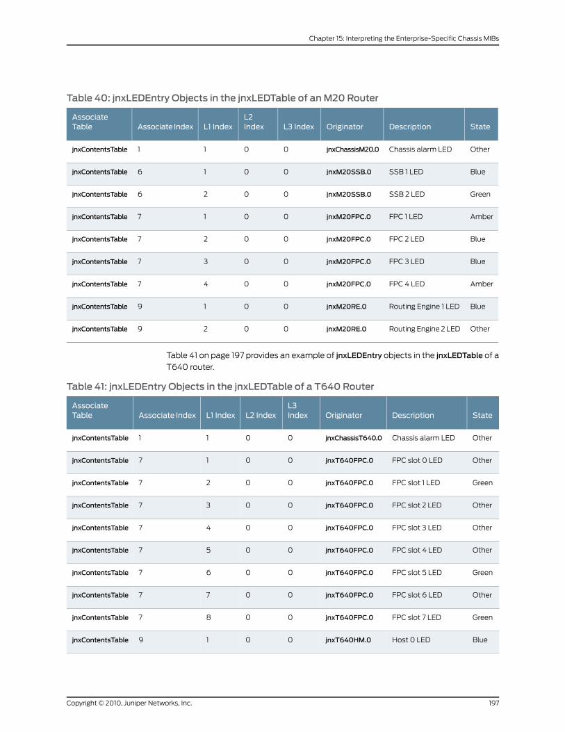
Table 40: jnxLEDEntry Objects in the jnxLEDTable of anM20 Router
StateDescriptionOriginatorL3 IndexL2IndexL1 IndexAssociate Index
AssociateTable
OtherChassis alarm LEDjnxChassisM20.00011jnxContentsTable
BlueSSB 1 LEDjnxM20SSB.00016jnxContentsTable
GreenSSB 2 LEDjnxM20SSB.00026jnxContentsTable
AmberFPC 1 LEDjnxM20FPC.00017jnxContentsTable
BlueFPC 2 LEDjnxM20FPC.00027jnxContentsTable
BlueFPC 3 LEDjnxM20FPC.00037jnxContentsTable
AmberFPC 4 LEDjnxM20FPC.00047jnxContentsTable
BlueRouting Engine 1 LEDjnxM20RE.00019jnxContentsTable
OtherRouting Engine 2 LEDjnxM20RE.00029jnxContentsTable
Table 41 on page 197 provides an example of jnxLEDEntry objects in the jnxLEDTable of a
T640 router.
Table 41: jnxLEDEntry Objects in the jnxLEDTable of a T640 Router
StateDescriptionOriginatorL3IndexL2 IndexL1 IndexAssociate Index
AssociateTable
OtherChassis alarm LEDjnxChassisT640.00011jnxContentsTable
OtherFPC slot 0 LEDjnxT640FPC.00017jnxContentsTable
GreenFPC slot 1 LEDjnxT640FPC.00027jnxContentsTable
OtherFPC slot 2 LEDjnxT640FPC.00037jnxContentsTable
OtherFPC slot 3 LEDjnxT640FPC.00047jnxContentsTable
OtherFPC slot 4 LEDjnxT640FPC.00057jnxContentsTable
GreenFPC slot 5 LEDjnxT640FPC.00067jnxContentsTable
OtherFPC slot 6 LEDjnxT640FPC.00077jnxContentsTable
GreenFPC slot 7 LEDjnxT640FPC.00087jnxContentsTable
BlueHost 0 LEDjnxT640HM.00019jnxContentsTable
197Copyright © 2010, Juniper Networks, Inc.
Chapter 15: Interpreting the Enterprise-Specific Chassis MIBs
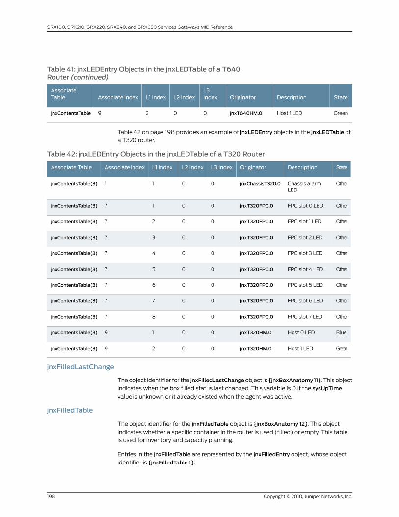
Table 41: jnxLEDEntry Objects in the jnxLEDTable of a T640Router (continued)
StateDescriptionOriginatorL3IndexL2 IndexL1 IndexAssociate Index
AssociateTable
GreenHost 1 LEDjnxT640HM.00029jnxContentsTable
Table 42 on page 198 provides an example of jnxLEDEntry objects in the jnxLEDTable of
a T320 router.
Table 42: jnxLEDEntry Objects in the jnxLEDTable of a T320 Router
StateDescriptionOriginatorL3 IndexL2 IndexL1 IndexAssociate IndexAssociate Table
OtherChassis alarmLED
jnxChassisT320.00011jnxContentsTable(3)
OtherFPC slot 0 LEDjnxT320FPC.00017jnxContentsTable(3)
OtherFPC slot 1 LEDjnxT320FPC.00027jnxContentsTable(3)
OtherFPC slot 2 LEDjnxT320FPC.00037jnxContentsTable(3)
OtherFPC slot 3 LEDjnxT320FPC.00047jnxContentsTable(3)
OtherFPC slot 4 LEDjnxT320FPC.00057jnxContentsTable(3)
OtherFPC slot 5 LEDjnxT320FPC.00067jnxContentsTable(3)
OtherFPC slot 6 LEDjnxT320FPC.00077jnxContentsTable(3)
OtherFPC slot 7 LEDjnxT320FPC.00087jnxContentsTable(3)
BlueHost 0 LEDjnxT320HM.00019jnxContentsTable(3)
GreenHost 1 LEDjnxT320HM.00029jnxContentsTable(3)
jnxFilledLastChange
The object identifier for the jnxFilledLastChangeobject is {jnxBoxAnatomy 11}. This object
indicates when the box filled status last changed. This variable is 0 if the sysUpTime
value is unknown or it already existed when the agent was active.
jnxFilledTable
The object identifier for the jnxFilledTable object is {jnxBoxAnatomy 12}. This object
indicates whether a specific container in the router is used (filled) or empty. This table
is used for inventory and capacity planning.
Entries in the jnxFilledTable are represented by the jnxFilledEntry object, whose object
identifier is {jnxFilledTable 1}.
Copyright © 2010, Juniper Networks, Inc.198
SRX100, SRX210, SRX220, SRX240, and SRX650 Services Gateways MIB Reference
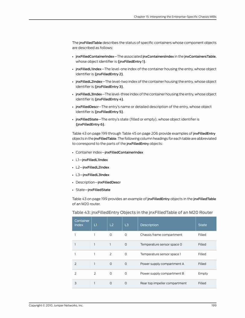
The jnxFilledTable describes the status of specific containers whose component objects
are described as follows:
• jnxFilledContainerIndex—The associated jnxContainersIndex in the jnxContainersTable,
whose object identifier is {jnxFilledEntry 1}.
• jnxFilledL1Index—The level-one index of the container housing the entry, whose object
identifier is {jnxFilledEntry 2}.
• jnxFilledL2Index—The level-two index of the container housing the entry, whose object
identifier is {jnxFilledEntry 3}.
• jnxFilledL3Index—The level-three index of the container housing the entry, whose object
identifier is {jnxFilledEntry 4}.
• jnxFilledDescr—The entry’s name or detailed description of the entry, whose object
identifier is {jnxFilledEntry 5}.
• jnxFilledState—The entry’s state (filled or empty), whose object identifier is
{jnxFilledEntry 6}.
Table 43 on page 199 through Table 45 on page 206 provide examples of jnxFilledEntry
objects in the jnxFilledTable. The following column headings for each table are abbreviated
to correspond to the parts of the jnxFilledEntry objects:
• Container index—jnxFilledContainerIndex
• L1—jnxFilledL1Index
• L2—jnxFilledL2Index
• L3—jnxFilledL3Index
• Description—jnxFilledDescr
• State—jnxFilledState
Table 43 on page 199 provides an example of jnxFilledEntry objects in the jnxFilledTable
of an M20 router.
Table 43: jnxFilledEntry Objects in the jnxFilledTable of anM20 Router
StateDescriptionL3L2L1ContainerIndex
FilledChassis frame compartment0011
FilledTemperature sensor space 00111
FilledTemperature sensor space 10211
FilledPower supply compartment A0012
EmptyPower supply compartment B0022
FilledRear top impeller compartment0013
199Copyright © 2010, Juniper Networks, Inc.
Chapter 15: Interpreting the Enterprise-Specific Chassis MIBs

Table 43: jnxFilledEntry Objects in the jnxFilledTable of anM20Router (continued)
StateDescriptionL3L2L1ContainerIndex
FilledFront bottom impeller compartment0023
FilledRear left fan compartment0014
FilledRight center fan compartment0024
FilledRear right fan compartment0034
FilledHost controller compartment0015
FilledSCB slot0016
EmptyFPC slot 00017
EmptyFPC slot 10027
FilledFPC slot 20037
FilledFPC slot 30047
EmptyFPC slot 40057
FilledFPC slot 50067
EmptyFPC slot 60077
EmptyFPC slot 70087
EmptyPIC space @ 0/0/*0118
EmptyPIC space @ 0/1/*0218
EmptyPIC space @ 0/2/*0318
EmptyPIC space @ 0/3/*0418
EmptyPIC space @ 1/0/*0128
EmptyPIC space @ 1/1/*0228
EmptyPIC space @ 1/2/*0328
EmptyPIC space @ 1/3/*0428
FilledPIC space @ 2/0/*0138
Copyright © 2010, Juniper Networks, Inc.200
SRX100, SRX210, SRX220, SRX240, and SRX650 Services Gateways MIB Reference
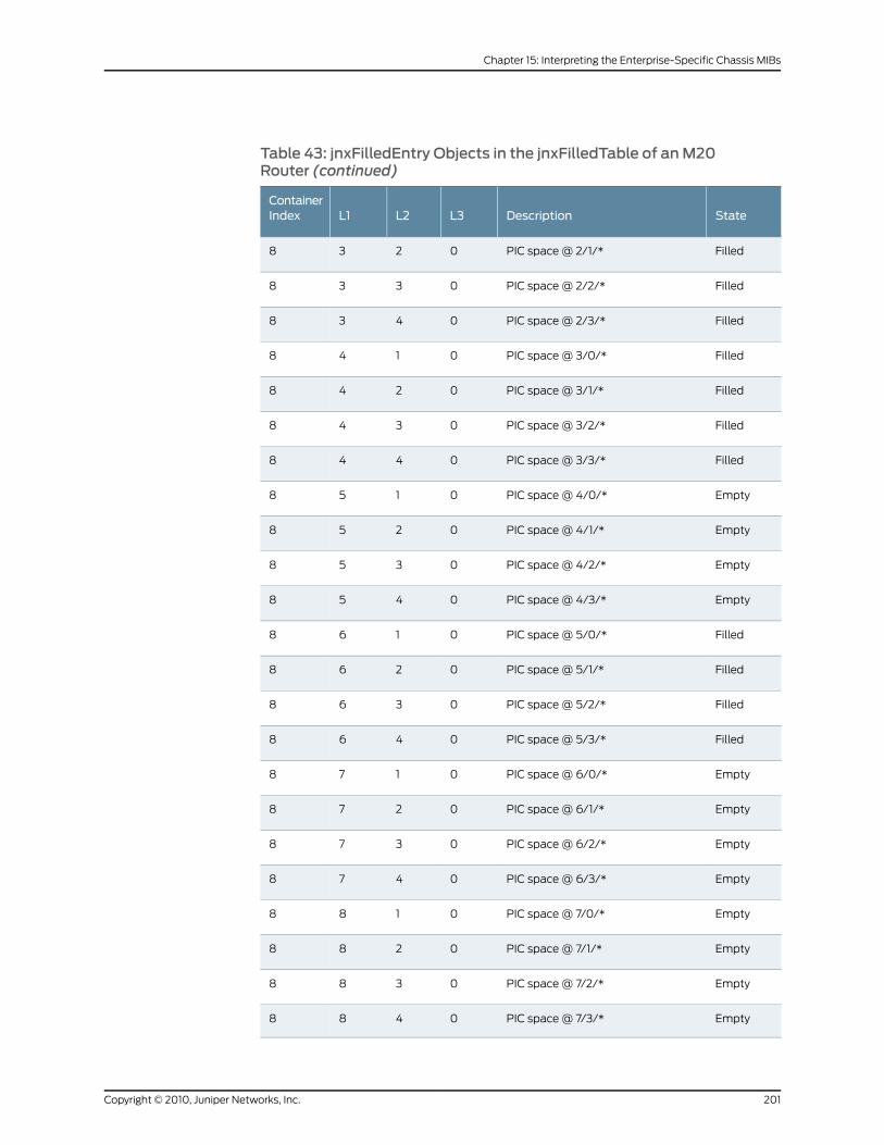
Table 43: jnxFilledEntry Objects in the jnxFilledTable of anM20Router (continued)
StateDescriptionL3L2L1ContainerIndex
FilledPIC space @ 2/1/*0238
FilledPIC space @ 2/2/*0338
FilledPIC space @ 2/3/*0438
FilledPIC space @ 3/0/*0148
FilledPIC space @ 3/1/*0248
FilledPIC space @ 3/2/*0348
FilledPIC space @ 3/3/*0448
EmptyPIC space @ 4/0/*0158
EmptyPIC space @ 4/1/*0258
EmptyPIC space @ 4/2/*0358
EmptyPIC space @ 4/3/*0458
FilledPIC space @ 5/0/*0168
FilledPIC space @ 5/1/*0268
FilledPIC space @ 5/2/*0368
FilledPIC space @ 5/3/*0468
EmptyPIC space @ 6/0/*0178
EmptyPIC space @ 6/1/*0278
EmptyPIC space @ 6/2/*0378
EmptyPIC space @ 6/3/*0478
EmptyPIC space @ 7/0/*0188
EmptyPIC space @ 7/1/*0288
EmptyPIC space @ 7/2/*0388
EmptyPIC space @ 7/3/*0488
201Copyright © 2010, Juniper Networks, Inc.
Chapter 15: Interpreting the Enterprise-Specific Chassis MIBs
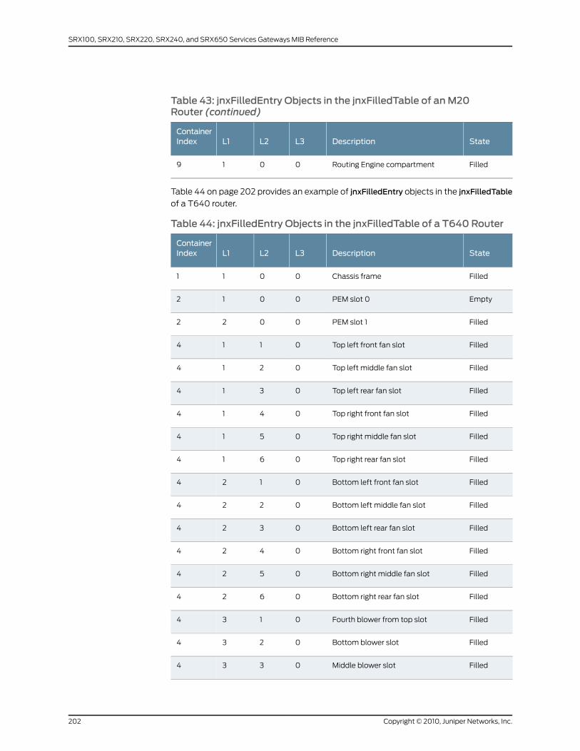
Table 43: jnxFilledEntry Objects in the jnxFilledTable of anM20Router (continued)
StateDescriptionL3L2L1ContainerIndex
FilledRouting Engine compartment0019
Table 44 on page 202 provides an example of jnxFilledEntry objects in the jnxFilledTable
of a T640 router.
Table 44: jnxFilledEntry Objects in the jnxFilledTable of a T640 Router
StateDescriptionL3L2L1ContainerIndex
FilledChassis frame0011
EmptyPEM slot 00012
FilledPEM slot 10022
FilledTop left front fan slot0114
FilledTop left middle fan slot0214
FilledTop left rear fan slot0314
FilledTop right front fan slot0414
FilledTop right middle fan slot0514
FilledTop right rear fan slot0614
FilledBottom left front fan slot0124
FilledBottom left middle fan slot0224
FilledBottom left rear fan slot0324
FilledBottom right front fan slot0424
FilledBottom right middle fan slot0524
FilledBottom right rear fan slot0624
FilledFourth blower from top slot0134
FilledBottom blower slot0234
FilledMiddle blower slot0334
Copyright © 2010, Juniper Networks, Inc.202
SRX100, SRX210, SRX220, SRX240, and SRX650 Services Gateways MIB Reference
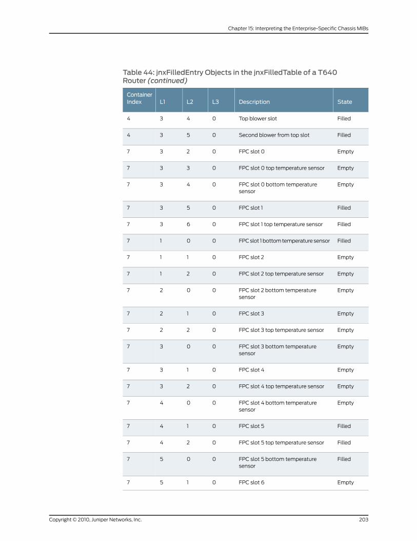
Table 44: jnxFilledEntry Objects in the jnxFilledTable of a T640Router (continued)
StateDescriptionL3L2L1ContainerIndex
FilledTop blower slot0434
FilledSecond blower from top slot0534
EmptyFPC slot 00237
EmptyFPC slot 0 top temperature sensor0337
EmptyFPC slot 0 bottom temperaturesensor
0437
FilledFPC slot 10537
FilledFPC slot 1 top temperature sensor0637
FilledFPC slot 1 bottom temperature sensor0017
EmptyFPC slot 20117
EmptyFPC slot 2 top temperature sensor0217
EmptyFPC slot 2 bottom temperaturesensor
0027
EmptyFPC slot 30127
EmptyFPC slot 3 top temperature sensor0227
EmptyFPC slot 3 bottom temperaturesensor
0037
EmptyFPC slot 40137
EmptyFPC slot 4 top temperature sensor0237
EmptyFPC slot 4 bottom temperaturesensor
0047
FilledFPC slot 50147
FilledFPC slot 5 top temperature sensor0247
FilledFPC slot 5 bottom temperaturesensor
0057
EmptyFPC slot 60157
203Copyright © 2010, Juniper Networks, Inc.
Chapter 15: Interpreting the Enterprise-Specific Chassis MIBs
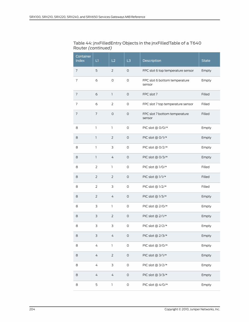
Table 44: jnxFilledEntry Objects in the jnxFilledTable of a T640Router (continued)
StateDescriptionL3L2L1ContainerIndex
EmptyFPC slot 6 top temperature sensor0257
EmptyFPC slot 6 bottom temperaturesensor
0067
FilledFPC slot 70167
FilledFPC slot 7 top temperature sensor0267
FilledFPC slot 7 bottom temperaturesensor
0077
EmptyPIC slot @ 0/0/*0118
EmptyPIC slot @ 0/1/*0218
EmptyPIC slot @ 0/2/*0318
EmptyPIC slot @ 0/3/*0418
FilledPIC slot @ 1/0/*0128
FilledPIC slot @ 1/1/*0228
FilledPIC slot @ 1/2/*0328
EmptyPIC slot @ 1/3/*0428
EmptyPIC slot @ 2/0/*0138
EmptyPIC slot @ 2/1/*0238
EmptyPIC slot @ 2/2/*0338
EmptyPIC slot @ 2/3/*0438
EmptyPIC slot @ 3/0/*0148
EmptyPIC slot @ 3/1/*0248
EmptyPIC slot @ 3/2/*0348
EmptyPIC slot @ 3/3/*0448
EmptyPIC slot @ 4/0/*0158
Copyright © 2010, Juniper Networks, Inc.204
SRX100, SRX210, SRX220, SRX240, and SRX650 Services Gateways MIB Reference
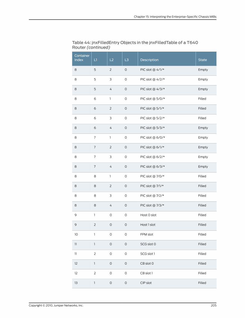
Table 44: jnxFilledEntry Objects in the jnxFilledTable of a T640Router (continued)
StateDescriptionL3L2L1ContainerIndex
EmptyPIC slot @ 4/1/*0258
EmptyPIC slot @ 4/2/*0358
EmptyPIC slot @ 4/3/*0458
FilledPIC slot @ 5/0/*0168
FilledPIC slot @ 5/1/*0268
FilledPIC slot @ 5/2/*0368
EmptyPIC slot @ 5/3/*0468
EmptyPIC slot @ 6/0/*0178
EmptyPIC slot @ 6/1/*0278
EmptyPIC slot @ 6/2/*0378
EmptyPIC slot @ 6/3/*0478
FilledPIC slot @ 7/0/*0188
FilledPIC slot @ 7/1/*0288
FilledPIC slot @ 7/2/*0388
FilledPIC slot @ 7/3/*0488
FilledHost 0 slot0019
FilledHost 1 slot0029
FilledFPM slot00110
FilledSCG slot 000111
FilledSCG slot 100211
FilledCB slot 000112
FilledCB slot 100212
FilledCIP slot00113
205Copyright © 2010, Juniper Networks, Inc.
Chapter 15: Interpreting the Enterprise-Specific Chassis MIBs
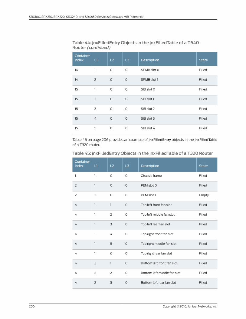
Table 44: jnxFilledEntry Objects in the jnxFilledTable of a T640Router (continued)
StateDescriptionL3L2L1ContainerIndex
FilledSPMB slot 000114
FilledSPMB slot 100214
FilledSIB slot 000115
FilledSIB slot 100215
FilledSIB slot 200315
FilledSIB slot 300415
FilledSIB slot 400515
Table 45 on page 206 provides an example of jnxFilledEntry objects in the jnxFilledTable
of a T320 router.
Table 45: jnxFilledEntry Objects in the jnxFilledTable of a T320 Router
StateDescriptionL3L2L1ContainerIndex
FilledChassis frame0011
FilledPEM slot 00012
EmptyPEM slot 10022
FilledTop left front fan slot0114
FilledTop left middle fan slot0214
FilledTop left rear fan slot0314
FilledTop right front fan slot0414
FilledTop right middle fan slot0514
FilledTop right rear fan slot0614
FilledBottom left front fan slot0124
FilledBottom left middle fan slot0224
FilledBottom left rear fan slot0324
Copyright © 2010, Juniper Networks, Inc.206
SRX100, SRX210, SRX220, SRX240, and SRX650 Services Gateways MIB Reference
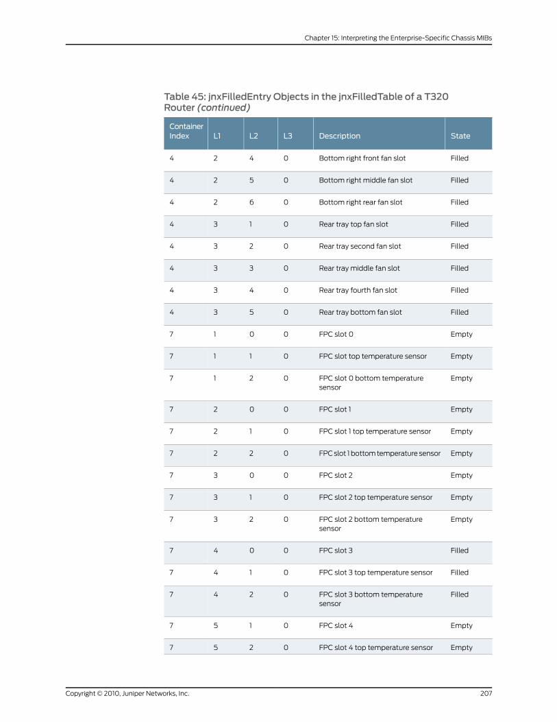
Table 45: jnxFilledEntry Objects in the jnxFilledTable of a T320Router (continued)
StateDescriptionL3L2L1ContainerIndex
FilledBottom right front fan slot0424
FilledBottom right middle fan slot0524
FilledBottom right rear fan slot0624
FilledRear tray top fan slot0134
FilledRear tray second fan slot0234
FilledRear tray middle fan slot0334
FilledRear tray fourth fan slot0434
FilledRear tray bottom fan slot0534
EmptyFPC slot 00017
EmptyFPC slot top temperature sensor0117
EmptyFPC slot 0 bottom temperaturesensor
0217
EmptyFPC slot 10027
EmptyFPC slot 1 top temperature sensor0127
EmptyFPC slot 1 bottom temperature sensor0227
EmptyFPC slot 20037
EmptyFPC slot 2 top temperature sensor0137
EmptyFPC slot 2 bottom temperaturesensor
0237
FilledFPC slot 30047
FilledFPC slot 3 top temperature sensor0147
FilledFPC slot 3 bottom temperaturesensor
0247
EmptyFPC slot 40157
EmptyFPC slot 4 top temperature sensor0257
207Copyright © 2010, Juniper Networks, Inc.
Chapter 15: Interpreting the Enterprise-Specific Chassis MIBs
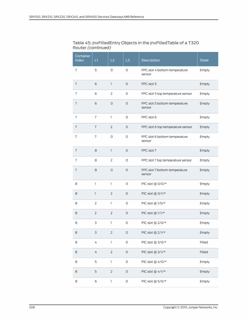
Table 45: jnxFilledEntry Objects in the jnxFilledTable of a T320Router (continued)
StateDescriptionL3L2L1ContainerIndex
EmptyFPC slot 4 bottom temperaturesensor
0057
EmptyFPC slot 50167
EmptyFPC slot 5 top temperature sensor0267
EmptyFPC slot 5 bottom temperaturesensor
0067
EmptyFPC slot 60177
EmptyFPC slot 6 top temperature sensor0277
EmptyFPC slot 6 bottom temperaturesensor
0077
EmptyFPC slot 70187
EmptyFPC slot 7 top temperature sensor0287
EmptyFPC slot 7 bottom temperaturesensor
0087
EmptyPIC slot @ 0/0/*0118
EmptyPIC slot @ 0/1/*0218
EmptyPIC slot @ 1/0/*0128
EmptyPIC slot @ 1/1/*0228
EmptyPIC slot @ 2/0/*0138
EmptyPIC slot @ 2/1/*0238
FilledPIC slot @ 3/0/*0148
FilledPIC slot @ 3/1/*0248
EmptyPIC slot @ 4/0/*0158
EmptyPIC slot @ 4/1/*0258
EmptyPIC slot @ 5/0/*0168
Copyright © 2010, Juniper Networks, Inc.208
SRX100, SRX210, SRX220, SRX240, and SRX650 Services Gateways MIB Reference
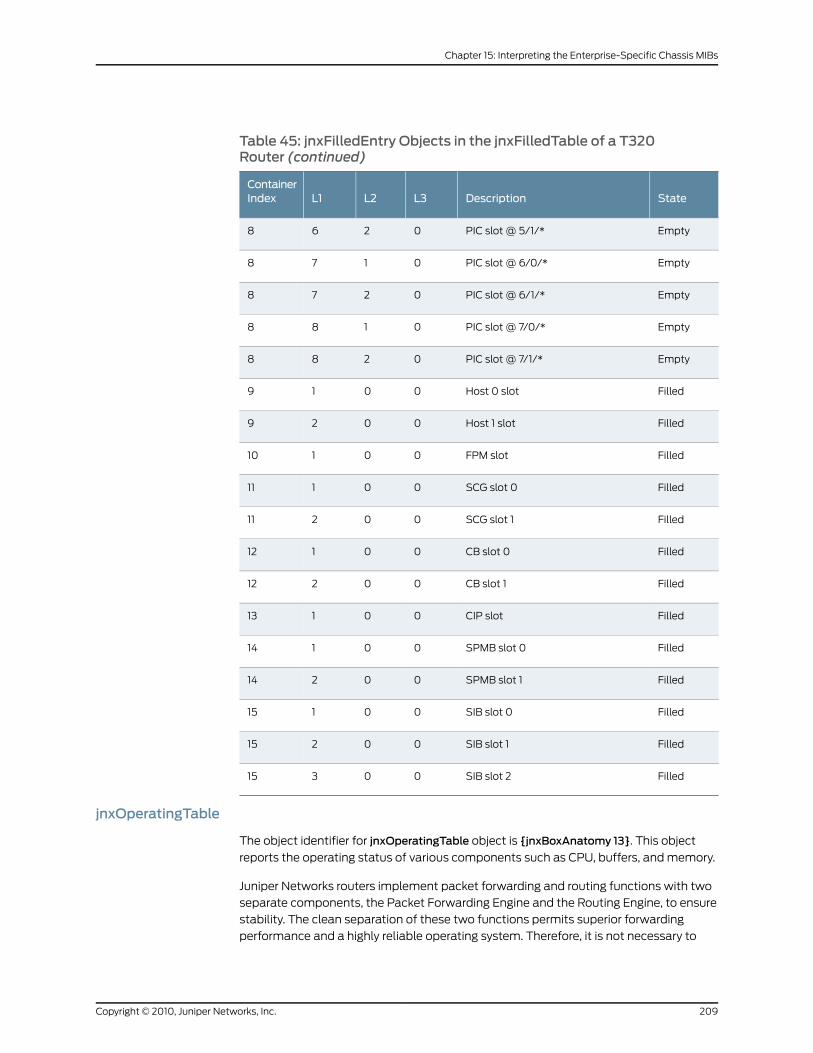
Table 45: jnxFilledEntry Objects in the jnxFilledTable of a T320Router (continued)
StateDescriptionL3L2L1ContainerIndex
EmptyPIC slot @ 5/1/*0268
EmptyPIC slot @ 6/0/*0178
EmptyPIC slot @ 6/1/*0278
EmptyPIC slot @ 7/0/*0188
EmptyPIC slot @ 7/1/*0288
FilledHost 0 slot0019
FilledHost 1 slot0029
FilledFPM slot00110
FilledSCG slot 000111
FilledSCG slot 100211
FilledCB slot 000112
FilledCB slot 100212
FilledCIP slot00113
FilledSPMB slot 000114
FilledSPMB slot 100214
FilledSIB slot 000115
FilledSIB slot 100215
FilledSIB slot 200315
jnxOperatingTable
The object identifier for jnxOperatingTable object is {jnxBoxAnatomy 13}. This object
reports the operating status of various components such as CPU, buffers, and memory.
Juniper Networks routers implement packet forwarding and routing functions with two
separate components, the Packet Forwarding Engine and the Routing Engine, to ensure
stability. The clean separation of these two functions permits superior forwarding
performance and a highly reliable operating system. Therefore, it is not necessary to
209Copyright © 2010, Juniper Networks, Inc.
Chapter 15: Interpreting the Enterprise-Specific Chassis MIBs
monitor CPU, memory, and buffer utilization, as is the case with traditional, monolithic
code base routers. The Routing Engine has its own CPU, memory, and buffers—separate
from those of the Packet Forwarding Engine. The ASIC-based Packet Forwarding Engine
forwards packets on all interfaces at wire speed, eliminating the need to monitor packet
buffers being exhausted. As a result, CPU utilization under 2 percent is normal.
Entries in the jnxOperatingTable are represented by the jnxOperatingEntry object, whose
object identifier is {jnxOperatingTable 1}.
The jnxOperatingTable describes the status of specific objects, which are described as
follows:
• jnxOperatingContents—The associated jnxContentsIndex in the jnxContentsTable,
whose object identifier is {jnxOperatingEntry 1}.
• jnxOperatingL1Index—The level-one index of the container housing the entry, whose
object identifier is {jnxOperatingEntry 2}.
• jnxOperatingL2Index—The level-two index of the container housing the entry, whose
object identifier is {jnxOperatingEntry 3}.
• jnxOperatingL3Index—The level-three index of the container housing the entry, whose
object identifier is {jnxOperatingEntry 4}.
• jnxOperatingDescr—The name or detailed description of the entry, whose object
identifier is {jnxOperatingEntry 5}.
• jnxOperatingState—The operating state of the entry, whose object identifier is
{jnxOperatingEntry 6}. The state can be any of the following:
• Unknown(1)—State of the component is unknown or unavailable
• Running(2)—Up and running as an active primary
• Ready(3)—Ready to run; not running yet
• Reset(4)—Held in reset; not ready yet
• RunningAtFullSpeed(5)—Valid for fans only
• Down(6)—Power supply is down or off
• Standby(7)—Running as a standby backup
• jnxOperatingTemp—The entry’s temperature, in degrees Celsius (°C), whose object
identifier is {jnxOperatingEntry 7}.
• jnxOperatingCPU—The CPU utilization percentage of the entry, whose object identifier
is {jnxOperatingEntry 8}. It is valid for the Control Board, the FPC, and the Routing
Engine. It is a 5-second rolling-weighted average calculated every second for each of
the CPUs. The value is sent to the Routing Engine every 10 seconds. The value for the
Routing Engine is calculated as the average CPU usage over a 5-second period. The
chassis process (chassisd) computes this value for every 5-second period and returns
the latest value from the cache when probed for the value of jnxOperatingCPU.9.1.0.0,
which maps to the Routing Engine CPU. The Routing Engine is the only object of interest;
Copyright © 2010, Juniper Networks, Inc.210
SRX100, SRX210, SRX220, SRX240, and SRX650 Services Gateways MIB Reference
the rest are most likely zero because CPUs on those cards are only used for
management purposes.
• jnxOperatingISR—The CPU utilization percentage of the entry in relation to the interrupt
service routing (ISR), whose object identifier is {jnxOperatingEntry 9}.
• jnxOperatingDRAMSize—The DRAM size of the entry, in bytes, whose object identifier
is {jnxOperatingEntry 10}. It is valid for the FPC, Routing Engine, and Control Board.
• jnxOperatingBuffer—The buffer pool utilization of the entry (a percentage), whose
object identifier is {jnxOperatingEntry 11}. It is valid for the FPC and Control Board as a
percentage of utilization. Buffers are normally fixed-length memory preallocated for
read/write, input/output, or reception/transmission. A measurement against these
buffers gives some indication of how busy the system is. The larger the percentage
utilization, the busier the system. In terms of absolute numbers, the bigger the buffer
size, the better the system can handle bursty traffic patterns.
• jnxOperatingHeap—The heap utilization of the entry, whose object identifier is
{jnxOperatingEntry 12}.
• jnxOperatingUpTime—The time interval, in 10-millisecond periods, that the entry has
been up and running, whose object identifier is {jnxOperatingEntry 13}.
• jnxOperatingLastRestart—The value of sysUpTime when the entry was last restarted,
whose object identifier is {jnxOperatingEntry 14}.
• jnxOperatingMemory—The entry’s installed memory size, in megabytes (MB), whose
object identifier is {jnxOperatingEntry 15}.
• jnxOperatingStateOrdered—The operating state of the entry, whose object identifier
is {jnxOperatingEntry 16}. The state is represented by one of the following values:
• Running(1)—Up and running as an active primary
• Standby(2)—Running as a standby backup
• Ready(3)—Ready to run; not running yet
• RunningAtFullSpeed(4)—Valid for fans only
• Reset(5)—Held in reset; not ready yet
• Down(6)—Power supply is down or off
• Unknown(7)—State of the component is unknown or unavailable
Table 46 on page 212 through Table 48 on page 216 provide examples of jnxOperatingEntry
objects. The following column headings for each table are abbreviated to correspond to
the parts of the jnxOperatingEntry objects:
• Contents index—jnxOperatingContents
• L1—jnxOperatingL1Index
• L2—jnxOperatingL2Index
• L3—jnxOperatingL3Index
211Copyright © 2010, Juniper Networks, Inc.
Chapter 15: Interpreting the Enterprise-Specific Chassis MIBs
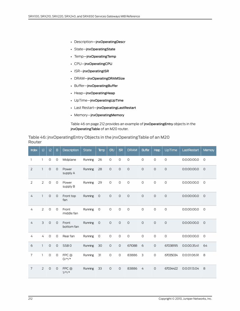
• Description—jnxOperatingDescr
• State—jnxOperatingState
• Temp—jnxOperatingTemp
• CPU—jnxOperatingCPU
• ISR—jnxOperatingISR
• DRAM—jnxOperatingDRAMSize
• Buffer—jnxOperatingBuffer
• Heap—jnxOperatingHeap
• UpTime—jnxOperatingUpTime
• Last Restart—jnxOperatingLastRestart
• Memory—jnxOperatingMemory
Table 46 on page 212 provides an example of jnxOperatingEntry objects in the
jnxOperatingTable of an M20 router.
Table 46: jnxOperatingEntry Objects in the jnxOperatingTable of anM20Router
MemoryLastRestartUpTimeHeapBufferDRAMISRCPUTempStateDescriptionL3L2L1Index
00:0:00:00.000000026RunningMidplane0011
00:0:00:00.000000028RunningPowersupply A
0012
00:0:00:00.000000029RunningPowersupply B
0022
00:0:00:00.00000000RunningFront topfan
0014
00:0:00:00.00000000RunningFrontmiddle fan
0024
00:0:00:00.00000000RunningFrontbottom fan
0034
00:0:00:00.00000000RunningRear fan0044
640:0:00:35.4167038195066710880030RunningSSB 00016
80:0:01:06.916703503403838860031RunningFPC @0/*/*
0017
80:0:01:13.046703442204838860033RunningFPC @1/*/*
0027
Copyright © 2010, Juniper Networks, Inc.212
SRX100, SRX210, SRX220, SRX240, and SRX650 Services Gateways MIB Reference
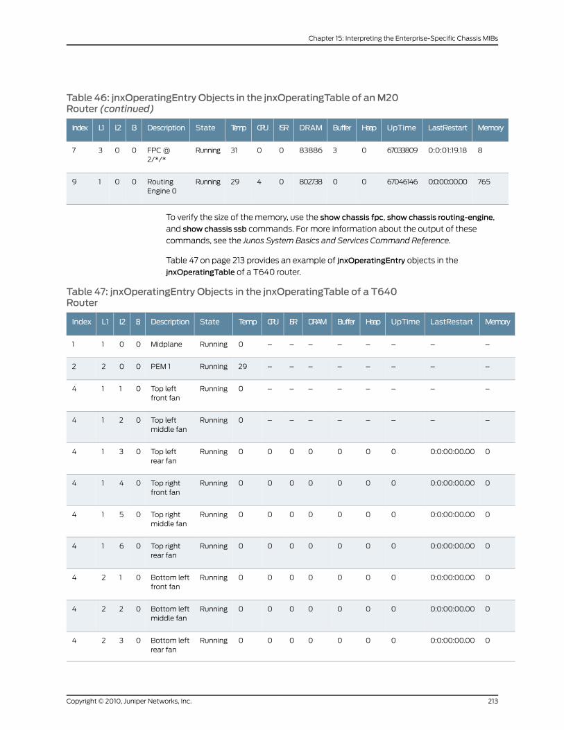
Table 46: jnxOperatingEntry Objects in the jnxOperatingTable of anM20Router (continued)
MemoryLastRestartUpTimeHeapBufferDRAMISRCPUTempStateDescriptionL3L2L1Index
80:0:01:19.186703380903838860031RunningFPC @2/*/*
0037
7650:0:00:00.0067046146008027380429RunningRoutingEngine 0
0019
To verify the size of the memory, use the show chassis fpc, show chassis routing-engine,
and show chassis ssb commands. For more information about the output of these
commands, see the Junos System Basics and Services Command Reference.
Table 47 on page 213 provides an example of jnxOperatingEntry objects in the
jnxOperatingTable of a T640 router.
Table 47: jnxOperatingEntry Objects in the jnxOperatingTable of a T640Router
MemoryLastRestartUpTimeHeapBufferDRAMISRCPUTempStateDescriptionL3L2L1Index
––––––––0RunningMidplane0011
––––––––29RunningPEM 10022
––––––––0RunningTop leftfront fan
0114
––––––––0RunningTop leftmiddle fan
0214
00:0:00:00.000000000RunningTop leftrear fan
0314
00:0:00:00.000000000RunningTop rightfront fan
0414
00:0:00:00.000000000RunningTop rightmiddle fan
0514
00:0:00:00.000000000RunningTop rightrear fan
0614
00:0:00:00.000000000RunningBottom leftfront fan
0124
00:0:00:00.000000000RunningBottom leftmiddle fan
0224
00:0:00:00.000000000RunningBottom leftrear fan
0324
213Copyright © 2010, Juniper Networks, Inc.
Chapter 15: Interpreting the Enterprise-Specific Chassis MIBs
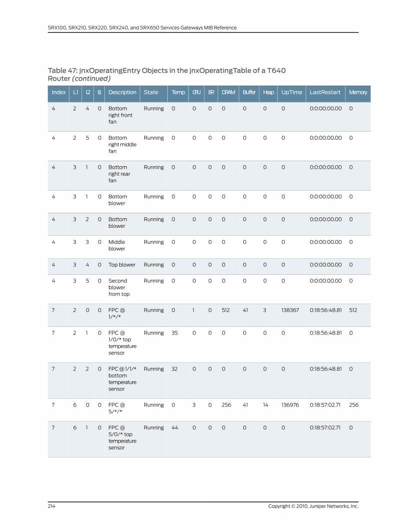
Table 47: jnxOperatingEntry Objects in the jnxOperatingTable of a T640Router (continued)
MemoryLastRestartUpTimeHeapBufferDRAMISRCPUTempStateDescriptionL3L2L1Index
00:0:00:00.000000000RunningBottomright frontfan
0424
00:0:00:00.000000000RunningBottomright middlefan
0524
00:0:00:00.000000000RunningBottomright rearfan
0134
00:0:00:00.000000000RunningBottomblower
0134
00:0:00:00.000000000RunningBottomblower
0234
00:0:00:00.000000000RunningMiddleblower
0334
00:0:00:00.000000000RunningTop blower0434
00:0:00:00.000000000RunningSecondblowerfrom top
0534
5120:18:56:48.81138367341512010RunningFPC @1/*/*
0027
00:18:56:48.8100000035RunningFPC @1/0/* toptemperaturesensor
0127
00:18:56:48.8100000032RunningFPC @ 1/1/*bottomtemperaturesensor
0227
2560:18:57:02.711369761441256030RunningFPC @5/*/*
0067
00:18:57:02.7100000044RunningFPC @5/0/* toptemperaturesensor
0167
Copyright © 2010, Juniper Networks, Inc.214
SRX100, SRX210, SRX220, SRX240, and SRX650 Services Gateways MIB Reference
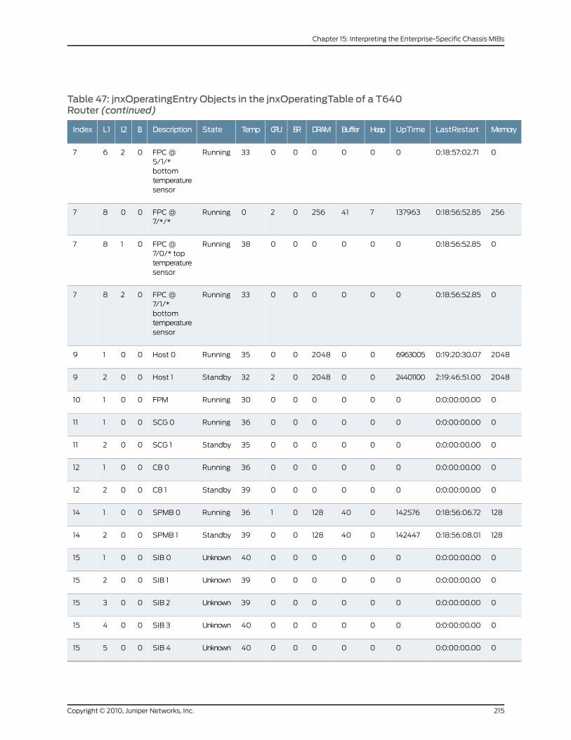
Table 47: jnxOperatingEntry Objects in the jnxOperatingTable of a T640Router (continued)
MemoryLastRestartUpTimeHeapBufferDRAMISRCPUTempStateDescriptionL3L2L1Index
00:18:57:02.7100000033RunningFPC @5/1/*bottomtemperaturesensor
0267
2560:18:56:52.85137963741256020RunningFPC @7/*/*
0087
00:18:56:52.8500000038RunningFPC @7/0/* toptemperaturesensor
0187
00:18:56:52.8500000033RunningFPC @7/1/*bottomtemperaturesensor
0287
20480:19:20:30.0769630050020480035RunningHost 00019
20482:19:46:51.00244011000020480232StandbyHost 10029
00:0:00:00.0000000030RunningFPM00110
00:0:00:00.0000000036RunningSCG 000111
00:0:00:00.0000000035StandbySCG 100211
00:0:00:00.0000000036RunningCB 000112
00:0:00:00.0000000039StandbyCB 100212
1280:18:56:06.721425760401280136RunningSPMB 000114
1280:18:56:08.011424470401280039StandbySPMB 100214
00:0:00:00.0000000040UnknownSIB 000115
00:0:00:00.0000000039UnknownSIB 100215
00:0:00:00.0000000039UnknownSIB 200315
00:0:00:00.0000000040UnknownSIB 300415
00:0:00:00.0000000040UnknownSIB 400515
215Copyright © 2010, Juniper Networks, Inc.
Chapter 15: Interpreting the Enterprise-Specific Chassis MIBs
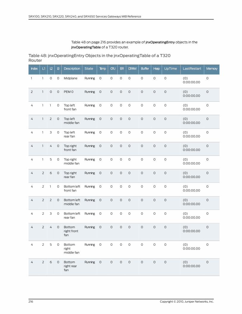
Table 48 on page 216 provides an example of jnxOperatingEntry objects in the
jnxOperatingTable of a T320 router.
Table 48: jnxOperatingEntry Objects in the jnxOperatingTable of a T320Router
MemoryLastRestartUpTimeHeapBufferDRAMISRCPUTempStateDescriptionL3L2L1Index
0(0)0:00:00.00
0000000RunningMidplane0011
0(0)0:00:00.00
0000000RunningPEM 00012
0(0)0:00:00.00
0000000RunningTop leftfront fan
0114
0(0)0:00:00.00
0000000RunningTop leftmiddle fan
0214
0(0)0:00:00.00
0000000RunningTop leftrear fan
0314
0(0)0:00:00.00
0000000RunningTop rightfront fan
0414
0(0)0:00:00.00
0000000RunningTop rightmiddle fan
0514
0(0)0:00:00.00
0000000RunningTop rightrear fan
0624
0(0)0:00:00.00
0000000RunningBottom leftfront fan
0124
0(0)0:00:00.00
0000000RunningBottom leftmiddle fan
0224
0(0)0:00:00.00
0000000RunningBottom leftrear fan
0324
0(0)0:00:00.00
0000000RunningBottomright frontfan
0424
0(0)0:00:00.00
0000000RunningBottomrightmiddle fan
0524
0(0)0:00:00.00
0000000RunningBottomright rearfan
0624
Copyright © 2010, Juniper Networks, Inc.216
SRX100, SRX210, SRX220, SRX240, and SRX650 Services Gateways MIB Reference

Table 48: jnxOperatingEntry Objects in the jnxOperatingTable of a T320Router (continued)
MemoryLastRestartUpTimeHeapBufferDRAMISRCPUTempStateDescriptionL3L2L1Index
0(0)0:00:00.00
0000000RunningRear traytop fan
0134
0(0)0:00:00.00
0000000RunningRear traysecond fan
0234
0(0)0:00:00.00
0000000RunningRear traymiddle fan
0334
0(0)0:00:00.00
0000000RunningRear trayfourth fan
0434
0(0)0:00:00.00
0000000RunningRear traybottom fan
0534
256(26190949)3 days,0:45:09.49
6568428741256010RunningFPC @3/*/*
0047
0(26190949)3 days,0:45:09.49
00000041RunningFPC @3/0/* toptemperaturesensor
0147
0(26190949)3 days,0:45:09.49
00000037RunningFPC @3/1/*bottomtemperaturesensor
0247
2048(32763004)3 days,19:00:30.04
327630010020480134RunningHost 00019
2048(110271900)12 days,18:18:39.00
1102719000020480132StandbyHost 10029
0(0)0:00:00.00
00000030RunningFPM00110
0(0)0:00:00.00
00000033RunningSCG 000111
0(0)0:00:00.00
00000031StandbySCG 100211
0(0)0:00:00.00
00000037RunningCB 000112
217Copyright © 2010, Juniper Networks, Inc.
Chapter 15: Interpreting the Enterprise-Specific Chassis MIBs
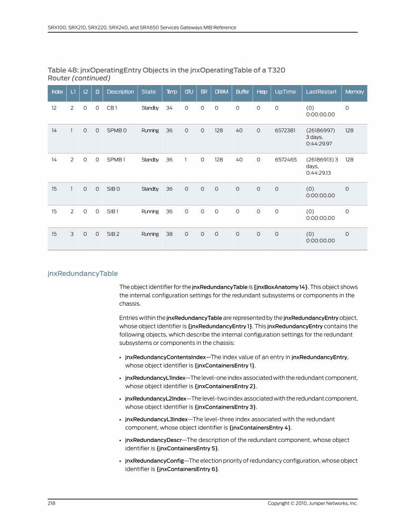
Table 48: jnxOperatingEntry Objects in the jnxOperatingTable of a T320Router (continued)
MemoryLastRestartUpTimeHeapBufferDRAMISRCPUTempStateDescriptionL3L2L1Index
0(0)0:00:00.00
00000034StandbyCB 100212
128(26186997)3 days,0:44:29.97
65723810401280036RunningSPMB 000114
128(26186913) 3days,0:44:29.13
65724650401280136StandbySPMB 100214
0(0)0:00:00.00
00000036StandbySIB 000115
0(0)0:00:00.00
00000036RunningSIB 100215
0(0)0:00:00.00
00000038RunningSIB 200315
jnxRedundancyTable
The object identifier for the jnxRedundancyTable is {jnxBoxAnatomy14}. This object shows
the internal configuration settings for the redundant subsystems or components in the
chassis.
Entries within the jnxRedundancyTableare represented by the jnxRedundancyEntryobject,
whose object identifier is {jnxRedundancyEntry 1}. This jnxRedundancyEntry contains the
following objects, which describe the internal configuration settings for the redundant
subsystems or components in the chassis:
• jnxRedundancyContentsIndex—The index value of an entry in jnxRedundancyEntry,
whose object identifier is {jnxContainersEntry 1}.
• jnxRedundancyL1Index—The level-one index associated with the redundant component,
whose object identifier is {jnxContainersEntry 2}.
• jnxRedundancyL2Index—The level-two index associated with the redundant component,
whose object identifier is {jnxContainersEntry 3}.
• jnxRedundancyL3Index—The level-three index associated with the redundant
component, whose object identifier is {jnxContainersEntry 4}.
• jnxRedundancyDescr—The description of the redundant component, whose object
identifier is {jnxContainersEntry 5}.
• jnxRedundancyConfig—The election priority of redundancy configuration, whose object
identifier is {jnxContainersEntry 6}.
Copyright © 2010, Juniper Networks, Inc.218
SRX100, SRX210, SRX220, SRX240, and SRX650 Services Gateways MIB Reference
• jnxRedundancyState—The current running state of the redundant component, whose
object identifier is {jnxContainersEntry 7}.
• jnxRedundancySwitchoverCount—The total number of switchovers, defined as a change
in the jnxRedundancyState from master to backup or vice versa, as perceived by the
redundant component since the Routing Engine is up and running, whose object
identifier is {jnxContainersEntry 8}.
• jnxRedundancySwitchoverTime—The value ofsysUpTimewhen the jnxRedundancyState
was last switched over from master to backup or vice versa, whose object identifier is
{jnxContainersEntry 9}.
• jnxRedundancySwitchoverReason—The reason for the last switchover to the redundant
component, whose object identifier is {jnxContainersEntry 10}.
• jnxKeepaliveHeartbeat—The period of sending keepalive messages between the master
and the backup subsystem, which is a system-wide preset value in seconds used by
internal mastership resolution, whose object identifier is {jnxContainersEntry 11}.
• jnxRedundancyKeepaliveTimeout—The timeout period in seconds used by the watchdog
timer before it initiates a switchover to the backup subsystem, whose object identifier
is {jnxContainersEntry 12}.
• jnxRedundancyKeepaliveElapsed—The elapsed time since the redundant component
received the last keepalive message from the outer subsystems, whose object identifier
is {jnxContainersEntry 13}.
• jnxRedundancyKeepaliveLoss—The total number of keepalive messages lost between
the master and the backup subsystems as perceived by the redundant component
since the Routing Engine is up and running, whose object identifier is {jnxContainersEntry
14}.
Table 49 on page 220 through Table 51 on page 222 provide examples of jnxRedundancyEntry
objects. The following column headings for each table are abbreviated to correspond to
the parts of the jnxOperatingTable objects:
• Contents index—jnxRedundancyContentsIndex
• L1—jnxRedundancyL1Index
• L2—jnxRedundancyL2Index
• L3—jnxRedundancyL3Index
• Description—jnxRedundancyDescr
• Config—jnxRedundancyConfig
• State—jnxRedundancyState
• Count—jnxRedundancySwitchoverCount
• Time—jnxRedundancySwitchoverTime
• Reason—jnxRedundancySwitchoverReason
• Heartbeat—jnxKeepaliveHeartbeat
219Copyright © 2010, Juniper Networks, Inc.
Chapter 15: Interpreting the Enterprise-Specific Chassis MIBs
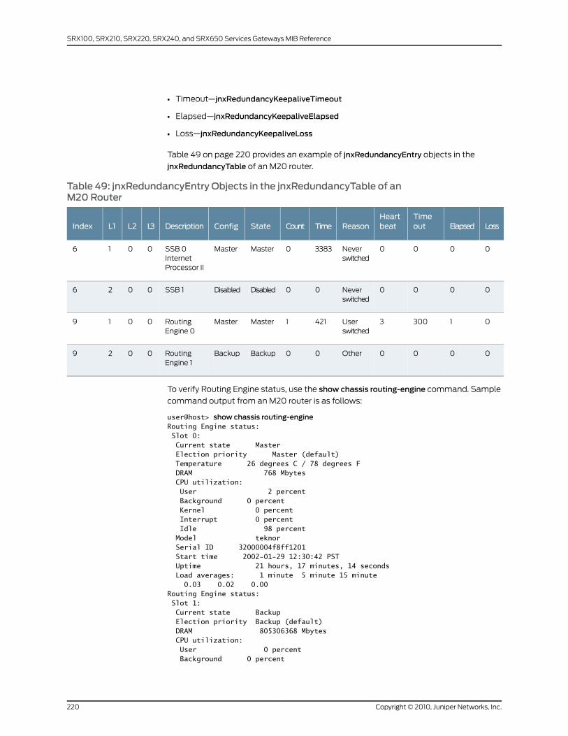
• Timeout—jnxRedundancyKeepaliveTimeout
• Elapsed—jnxRedundancyKeepaliveElapsed
• Loss—jnxRedundancyKeepaliveLoss
Table 49 on page 220 provides an example of jnxRedundancyEntry objects in the
jnxRedundancyTable of an M20 router.
Table 49: jnxRedundancyEntry Objects in the jnxRedundancyTable of anM20 Router
LossElapsedTimeout
HeartbeatReasonTimeCountStateConfigDescriptionL3L2L1Index
0000Neverswitched
33830MasterMasterSSB 0InternetProcessor II
0016
0000Neverswitched
00DisabledDisabledSSB 10026
013003Userswitched
4211MasterMasterRoutingEngine 0
0019
0000Other00BackupBackupRoutingEngine 1
0029
To verify Routing Engine status, use the show chassis routing-engine command. Sample
command output from an M20 router is as follows:
user@host> show chassis routing-engineRouting Engine status: Slot 0: Current state Master Election priority Master (default) Temperature 26 degrees C / 78 degrees F DRAM 768 Mbytes CPU utilization: User 2 percent Background 0 percent Kernel 0 percent Interrupt 0 percent Idle 98 percent Model teknor Serial ID 32000004f8ff1201 Start time 2002-01-29 12:30:42 PST Uptime 21 hours, 17 minutes, 14 seconds Load averages: 1 minute 5 minute 15 minute 0.03 0.02 0.00Routing Engine status: Slot 1: Current state Backup Election priority Backup (default) DRAM 805306368 Mbytes CPU utilization: User 0 percent Background 0 percent
Copyright © 2010, Juniper Networks, Inc.220
SRX100, SRX210, SRX220, SRX240, and SRX650 Services Gateways MIB Reference
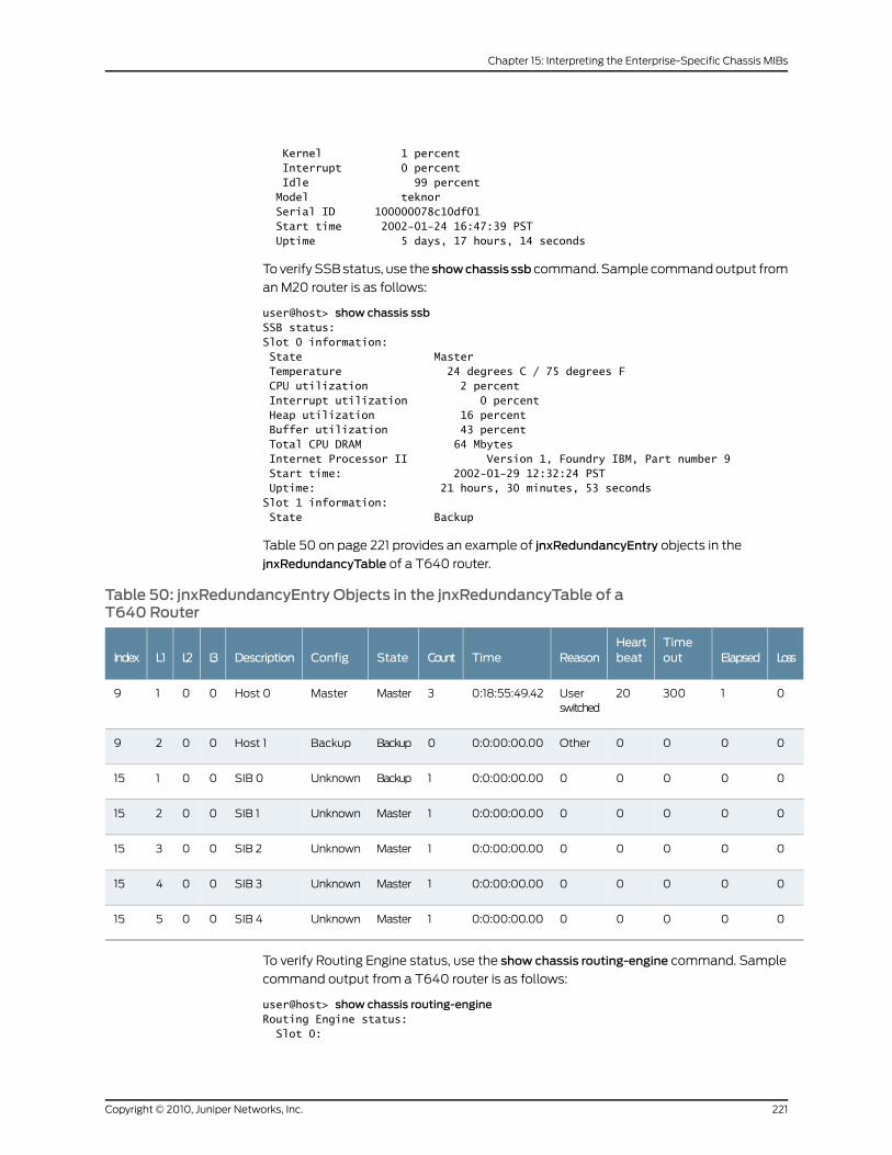
Kernel 1 percent Interrupt 0 percent Idle 99 percent Model teknor Serial ID 100000078c10df01 Start time 2002-01-24 16:47:39 PST Uptime 5 days, 17 hours, 14 seconds
To verify SSB status, use the showchassis ssb command. Sample command output from
an M20 router is as follows:
user@host> show chassis ssbSSB status:Slot 0 information: State Master Temperature 24 degrees C / 75 degrees F CPU utilization 2 percent Interrupt utilization 0 percent Heap utilization 16 percent Buffer utilization 43 percent Total CPU DRAM 64 Mbytes Internet Processor II Version 1, Foundry IBM, Part number 9 Start time: 2002-01-29 12:32:24 PST Uptime: 21 hours, 30 minutes, 53 secondsSlot 1 information: State Backup
Table 50 on page 221 provides an example of jnxRedundancyEntry objects in the
jnxRedundancyTable of a T640 router.
Table 50: jnxRedundancyEntry Objects in the jnxRedundancyTable of aT640 Router
LossElapsedTimeout
HeartbeatReasonTimeCountStateConfigDescriptionL3L2L1Index
0130020Userswitched
0:18:55:49.423MasterMasterHost 00019
0000Other0:0:00:00.000BackupBackupHost 10029
000000:0:00:00.001BackupUnknownSIB 000115
000000:0:00:00.001MasterUnknownSIB 100215
000000:0:00:00.001MasterUnknownSIB 200315
000000:0:00:00.001MasterUnknownSIB 300415
000000:0:00:00.001MasterUnknownSIB 400515
To verify Routing Engine status, use the show chassis routing-engine command. Sample
command output from a T640 router is as follows:
user@host> show chassis routing-engineRouting Engine status: Slot 0:
221Copyright © 2010, Juniper Networks, Inc.
Chapter 15: Interpreting the Enterprise-Specific Chassis MIBs
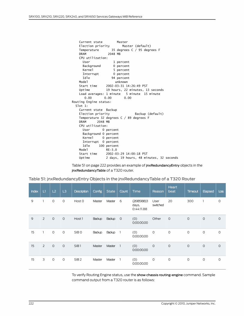
Current state Master Election priority Master (default) Temperature 35 degrees C / 95 degrees F DRAM 2048 MB CPU utilization: User 1 percent Background 0 percent Kernel 5 percent Interrupt 0 percent Idle 94 percent Model unknown Start time 2002-03-31 14:26:49 PST Uptime 19 hours, 22 minutes, 13 seconds Load averages: 1 minute 5 minute 15 minute 0.00 0.00 0.00Routing Engine status: Slot 1: Current state Backup Election priority Backup (default) Temperature 32 degrees C / 89 degrees F DRAM 2048 MB CPU utilization: User 0 percent Background 0 percent Kernel 0 percent Interrupt 0 percent Idle 100 percent Model RE-3.0 Start time 2002-03-29 14:00:18 PST Uptime 2 days, 19 hours, 48 minutes, 32 seconds
Table 51 on page 222 provides an example of jnxRedundancyEntry objects in the
jnxRedundancyTable of a T320 router.
Table 51: jnxRedundancyEntry Objects in the jnxRedundancyTable of a T320 Router
LossElapsedTimeoutHeartbeatReasonTimeCountStateConfigDescriptionL3L2L1Index
0130020Userswitched
(26185188)3days,0:44:11.88
6MasterMasterHost 00019
0000Other(0)0:00:00.00
0BackupBackupHost 10029
00000(0)0:00:00.00
1BackupBackupSIB 000115
00000(0)0:00:00.00
1MasterMasterSIB 100215
00000(0)0:00:00.00
1MasterMasterSIB 200315
To verify Routing Engine status, use the show chassis routing-engine command. Sample
command output from a T320 router is as follows:
Copyright © 2010, Juniper Networks, Inc.222
SRX100, SRX210, SRX220, SRX240, and SRX650 Services Gateways MIB Reference
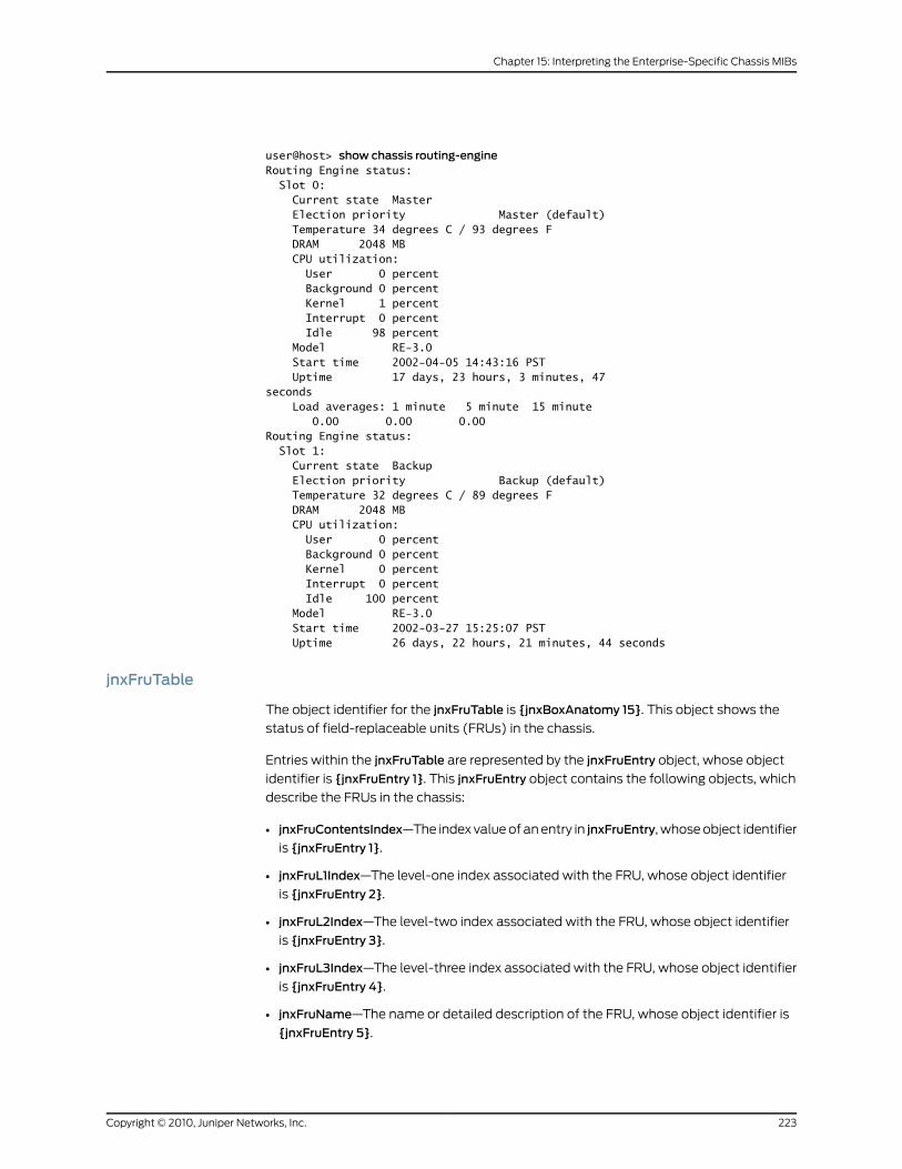
user@host> show chassis routing-engineRouting Engine status: Slot 0: Current state Master Election priority Master (default) Temperature 34 degrees C / 93 degrees F DRAM 2048 MB CPU utilization: User 0 percent Background 0 percent Kernel 1 percent Interrupt 0 percent Idle 98 percent Model RE-3.0 Start time 2002-04-05 14:43:16 PST Uptime 17 days, 23 hours, 3 minutes, 47seconds Load averages: 1 minute 5 minute 15 minute 0.00 0.00 0.00Routing Engine status: Slot 1: Current state Backup Election priority Backup (default) Temperature 32 degrees C / 89 degrees F DRAM 2048 MB CPU utilization: User 0 percent Background 0 percent Kernel 0 percent Interrupt 0 percent Idle 100 percent Model RE-3.0 Start time 2002-03-27 15:25:07 PST Uptime 26 days, 22 hours, 21 minutes, 44 seconds
jnxFruTable
The object identifier for the jnxFruTable is {jnxBoxAnatomy 15}. This object shows the
status of field-replaceable units (FRUs) in the chassis.
Entries within the jnxFruTable are represented by the jnxFruEntry object, whose object
identifier is {jnxFruEntry 1}. This jnxFruEntry object contains the following objects, which
describe the FRUs in the chassis:
• jnxFruContentsIndex—The index value of an entry in jnxFruEntry, whose object identifier
is {jnxFruEntry 1}.
• jnxFruL1Index—The level-one index associated with the FRU, whose object identifier
is {jnxFruEntry 2}.
• jnxFruL2Index—The level-two index associated with the FRU, whose object identifier
is {jnxFruEntry 3}.
• jnxFruL3Index—The level-three index associated with the FRU, whose object identifier
is {jnxFruEntry 4}.
• jnxFruName—The name or detailed description of the FRU, whose object identifier is
{jnxFruEntry 5}.
223Copyright © 2010, Juniper Networks, Inc.
Chapter 15: Interpreting the Enterprise-Specific Chassis MIBs
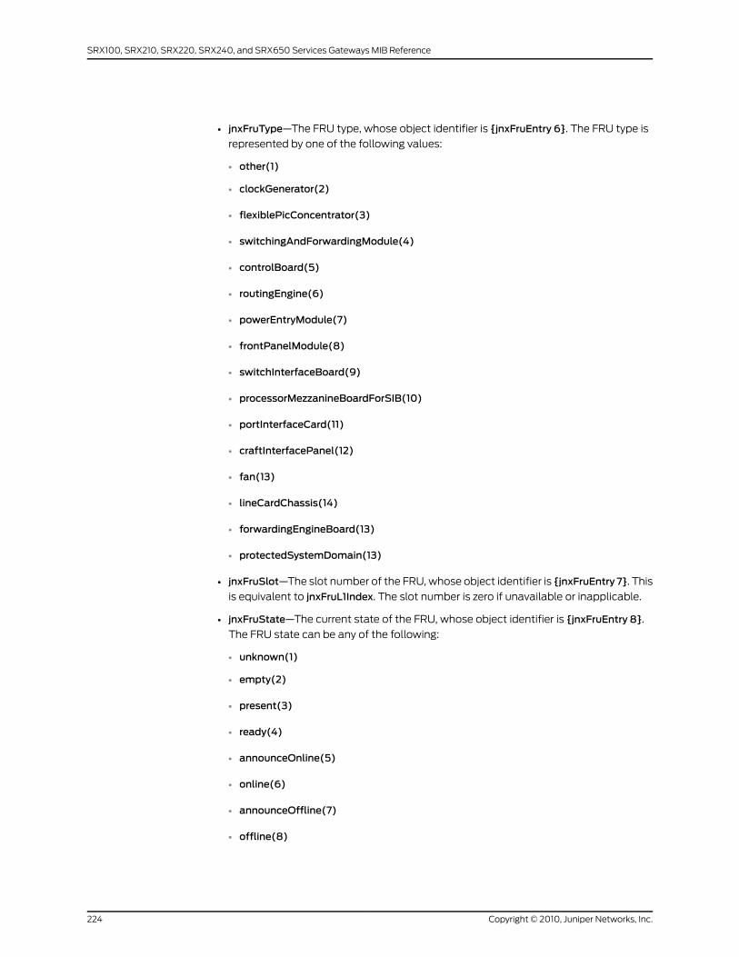
• jnxFruType—The FRU type, whose object identifier is {jnxFruEntry 6}. The FRU type is
represented by one of the following values:
• other(1)
• clockGenerator(2)
• flexiblePicConcentrator(3)
• switchingAndForwardingModule(4)
• controlBoard(5)
• routingEngine(6)
• powerEntryModule(7)
• frontPanelModule(8)
• switchInterfaceBoard(9)
• processorMezzanineBoardForSIB(10)
• portInterfaceCard(11)
• craftInterfacePanel(12)
• fan(13)
• lineCardChassis(14)
• forwardingEngineBoard(13)
• protectedSystemDomain(13)
• jnxFruSlot—The slot number of the FRU, whose object identifier is {jnxFruEntry 7}. This
is equivalent to jnxFruL1Index. The slot number is zero if unavailable or inapplicable.
• jnxFruState—The current state of the FRU, whose object identifier is {jnxFruEntry 8}.
The FRU state can be any of the following:
• unknown(1)
• empty(2)
• present(3)
• ready(4)
• announceOnline(5)
• online(6)
• announceOffline(7)
• offline(8)
Copyright © 2010, Juniper Networks, Inc.224
SRX100, SRX210, SRX220, SRX240, and SRX650 Services Gateways MIB Reference

• diagnostic(9)
• standby(10)
• jnxFruTemp—The temperature of the FRU, in degrees Celsius, whose object identifier
is {jnxFruEntry 9}. The value is zero if unavailable or inapplicable.
• jnxFruOfflineReason—The reason the FRU is offline, whose object identifier is
{jnxFruEntry 10}. The reason is represented by the following values:
• unknown(1)—Unknown or other
• none(2)—None
• error(3)—Error
• noPower(4)—No power
• configPowerOff(5)—Configured to power off
• configHoldInReset(6)—Configured to hold in reset
• cliCommand(7)—Brought offline by a command-line interface (CLI) command
• buttonPress(8)—Brought offline by button press
• cliRestart(9)—Restarted by CLI command
• overtempShutdown(10)—Overtemperature shutdown
• masterClockDown(11)—Master clock down
• singleSfmModeChange(12)—Single SFM mode change
• packetSchedulingModeChange(13)—Packet scheduling mode change
• physicalRemoval(14)—Physical removal
• unresponsiveRestart(15)—Restarting unresponsive board
• sonetClockAbsent(16)—SONET out clock absent
• jnxFruLastPowerOff—The value of sysUpTime when this subject was last powered off,
whose object identifier is {jnxFruEntry 11}. The value is zero if unavailable or inapplicable.
• jnxFruLastPowerOn—The value of sysUpTime when this subject was last powered on,
whose object identifier is {jnxFruEntry 12}. The value is zero if unavailable or inapplicable.
• jnxFruPowerUpTime—The time interval in 10-millisecond periods that this subject has
been up and running since the last power-on time, whose object identifier is {jnxFruEntry
13}. The value is zero if unavailable or inapplicable.
• jnxFruChassisId—The chassis type of this subject. The object identifier for this object
is {jnxFruEntry 14}.
225Copyright © 2010, Juniper Networks, Inc.
Chapter 15: Interpreting the Enterprise-Specific Chassis MIBs
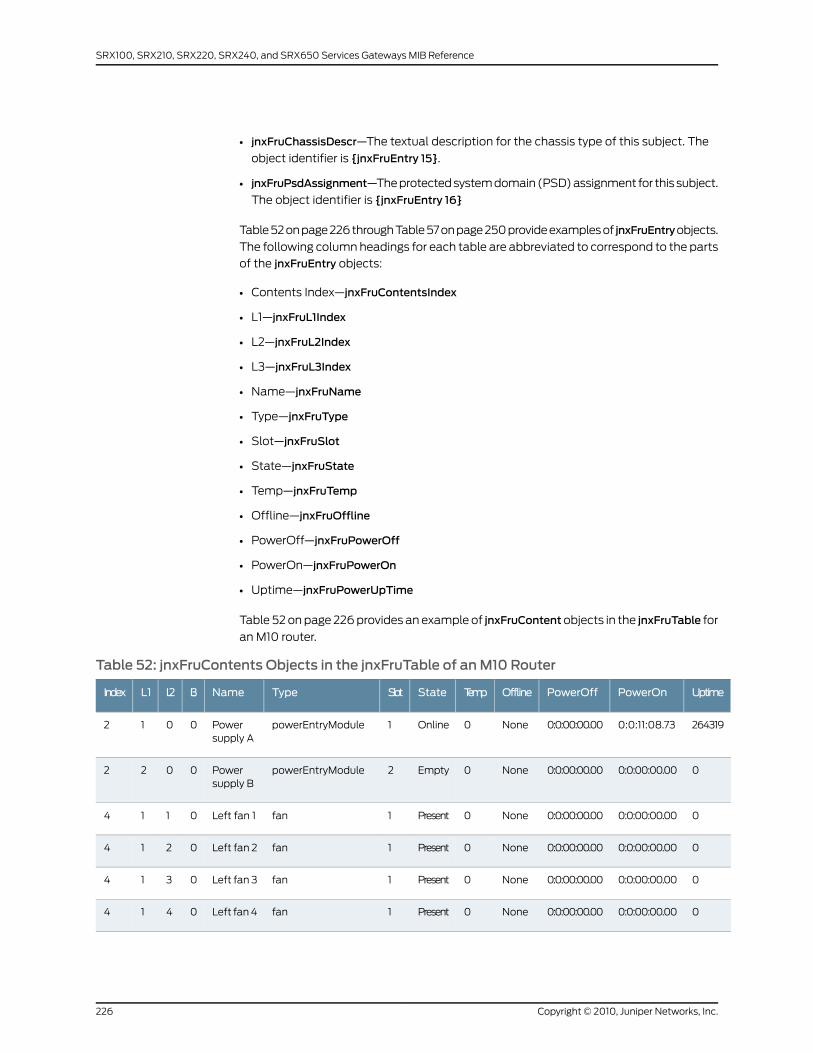
• jnxFruChassisDescr—The textual description for the chassis type of this subject. The
object identifier is {jnxFruEntry 15}.
• jnxFruPsdAssignment—The protected system domain (PSD) assignment for this subject.
The object identifier is {jnxFruEntry 16}
Table 52 on page 226 through Table 57 on page 250 provide examples of jnxFruEntryobjects.
The following column headings for each table are abbreviated to correspond to the parts
of the jnxFruEntry objects:
• Contents Index—jnxFruContentsIndex
• L1—jnxFruL1Index
• L2—jnxFruL2Index
• L3—jnxFruL3Index
• Name—jnxFruName
• Type—jnxFruType
• Slot—jnxFruSlot
• State—jnxFruState
• Temp—jnxFruTemp
• Offline—jnxFruOffline
• PowerOff—jnxFruPowerOff
• PowerOn—jnxFruPowerOn
• Uptime—jnxFruPowerUpTime
Table 52 on page 226 provides an example of jnxFruContentobjects in the jnxFruTable for
an M10 router.
Table 52: jnxFruContents Objects in the jnxFruTable of anM10 Router
UptimePowerOnPowerOffOfflineTempStateSlotTypeNameL3L2L1Index
2643190:0:11:08.730:0:00:00.00None0Online1powerEntryModulePowersupply A
0012
00:0:00:00.000:0:00:00.00None0Empty2powerEntryModulePowersupply B
0022
00:0:00:00.000:0:00:00.00None0Present1fanLeft fan 10114
00:0:00:00.000:0:00:00.00None0Present1fanLeft fan 20214
00:0:00:00.000:0:00:00.00None0Present1fanLeft fan 30314
00:0:00:00.000:0:00:00.00None0Present1fanLeft fan 40414
Copyright © 2010, Juniper Networks, Inc.226
SRX100, SRX210, SRX220, SRX240, and SRX650 Services Gateways MIB Reference

Table 52: jnxFruContents Objects in the jnxFruTable of anM10Router (continued)
UptimePowerOnPowerOffOfflineTempStateSlotTypeNameL3L2L1Index
00:0:00:00.000:0:00:00.00None24Online1controlBoardFEBInternetProcessorII
0016
00:0:00:00.000:0:00:00.00None24Online1flexiblePicConcentratorFPC @0/*/*
0017
00:0:00:00.000:0:00:00.00None24Online2flexiblePicConcentratorFPC @1/*/*
0027
00:0:00:00.000:0:00:00.00None24Ready1portInterfaceCardPIC: @0/0/*
0118
00:0:00:00.000:0:00:00.00None24Ready1portInterfaceCardPIC: 1xMonitor@ 0/1/*
0218
00:0:00:00.000:0:00:00.00None24Ready1portInterfaceCardPIC: 1xOC-12ATM, MM@ 0/2/*
0318
00:0:00:00.000:0:00:00.00None24Ready1portInterfaceCardPIC: 4xT3 @0/3/*
0418
00:0:00:00.000:0:00:00.00None24Ready2portInterfaceCardPIC: 4xOC-3SONET,SMIR @1/0/*
0128
00:0:00:00.000:0:00:00.00None24Ready2portInterfaceCardPIC: 4xOC-3SONET,MM @1/1/*
0228
00:0:00:00.000:0:00:00.00None24Ready2portInterfaceCardPIC: 2xOC-3ATM, MM@ 1/2/*
0328
00:0:00:00.000:0:00:00.00None24Ready2portInterfaceCardPIC: 2xOC-3ATM, MM@ 1/3/*
0428
00:0:00:00.000:0:00:00.00None27Online1routingEngineRoutingEngine
0019
227Copyright © 2010, Juniper Networks, Inc.
Chapter 15: Interpreting the Enterprise-Specific Chassis MIBs
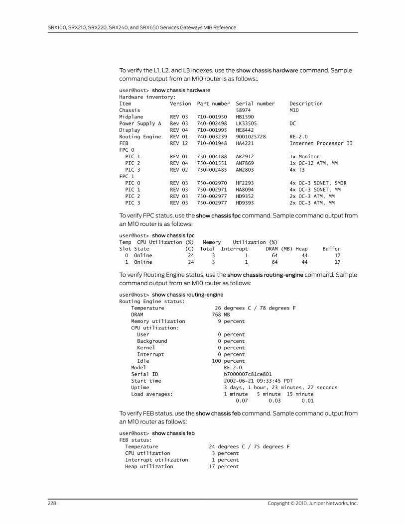
To verify the L1, L2, and L3 indexes, use the show chassis hardware command. Sample
command output from an M10 router is as follows:.
user@host> show chassis hardwareHardware inventory:Item Version Part number Serial number DescriptionChassis 58974 M10Midplane REV 03 710-001950 HB1590Power Supply A Rev 03 740-002498 LK33505 DCDisplay REV 04 710-001995 HE8442Routing Engine REV 01 740-003239 9001025728 RE-2.0FEB REV 12 710-001948 HA4221 Internet Processor IIFPC 0 PIC 1 REV 01 750-004188 AR2912 1x Monitor PIC 2 REV 04 750-001551 AN7869 1x OC-12 ATM, MM PIC 3 REV 02 750-002485 AN2803 4x T3FPC 1 PIC 0 REV 03 750-002970 HF2293 4x OC-3 SONET, SMIR PIC 1 REV 03 750-002971 HA8094 4x OC-3 SONET, MM PIC 2 REV 03 750-002977 HD9352 2x OC-3 ATM, MM PIC 3 REV 03 750-002977 HD9393 2x OC-3 ATM, MM
To verify FPC status, use the showchassis fpc command. Sample command output from
an M10 router is as follows:
user@host> show chassis fpcTemp CPU Utilization (%) Memory Utilization (%)Slot State (C) Total Interrupt DRAM (MB) Heap Buffer 0 Online 24 3 1 64 44 17 1 Online 24 3 1 64 44 17
To verify Routing Engine status, use the show chassis routing-engine command. Sample
command output from an M10 router as follows:
user@host> show chassis routing-engineRouting Engine status: Temperature 26 degrees C / 78 degrees F DRAM 768 MB Memory utilization 9 percent CPU utilization: User 0 percent Background 0 percent Kernel 0 percent Interrupt 0 percent Idle 100 percent Model RE-2.0 Serial ID b7000007c81ce801 Start time 2002-06-21 09:33:45 PDT Uptime 3 days, 1 hour, 23 minutes, 27 seconds Load averages: 1 minute 5 minute 15 minute 0.07 0.03 0.01
To verify FEB status, use the showchassis feb command. Sample command output from
an M10 router as follows:
user@host> show chassis febFEB status: Temperature 24 degrees C / 75 degrees F CPU utilization 3 percent Interrupt utilization 1 percent Heap utilization 17 percent
Copyright © 2010, Juniper Networks, Inc.228
SRX100, SRX210, SRX220, SRX240, and SRX650 Services Gateways MIB Reference
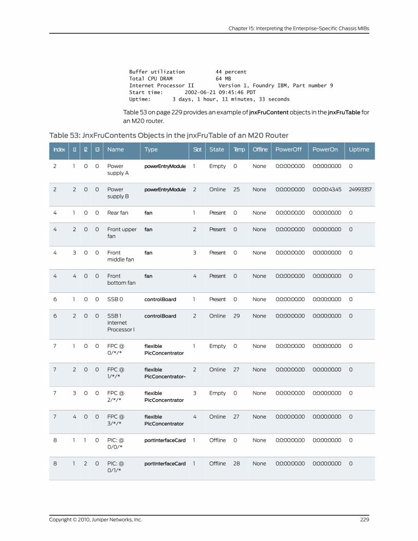
Buffer utilization 44 percent Total CPU DRAM 64 MB Internet Processor II Version 1, Foundry IBM, Part number 9 Start time: 2002-06-21 09:45:46 PDT Uptime: 3 days, 1 hour, 11 minutes, 33 seconds
Table 53 on page 229 provides an example of jnxFruContentobjects in the jnxFruTable for
an M20 router.
Table 53: JnxFruContents Objects in the jnxFruTable of anM20 Router
UptimePowerOnPowerOffOfflineTempStateSlotTypeNameL3L2L1Index
00:0:00:00.000:0:00:00.00None0Empty1powerEntryModulePowersupply A
0012
249933570:0:00:43.450:0:00:00.00None25Online2powerEntryModulePowersupply B
0022
00:0:00:00.000:0:00:00.00None0Present1fanRear fan0014
00:0:00:00.000:0:00:00.00None0Present2fanFront upperfan
0024
00:0:00:00.000:0:00:00.00None0Present3fanFrontmiddle fan
0034
00:0:00:00.000:0:00:00.00None0Present4fanFrontbottom fan
0044
00:0:00:00.000:0:00:00.00None0Present1controlBoardSSB 00016
00:0:00:00.000:0:00:00.00None29Online2controlBoardSSB 1InternetProcessor I
0026
00:0:00:00.000:0:00:00.00None0Empty1flexiblePicConcentrator
FPC @0/*/*
0017
00:0:00:00.000:0:00:00.00None27Online2flexiblePicConcentrator-
FPC @1/*/*
0027
00:0:00:00.000:0:00:00.00None0Empty3flexiblePicConcentrator
FPC @2/*/*
0037
00:0:00:00.000:0:00:00.00None27Online4flexiblePicConcentrator
FPC @3/*/*
0047
00:0:00:00.000:0:00:00.00None0Offline1portInterfaceCardPIC: @0/0/*
0118
00:0:00:00.000:0:00:00.00None28Offline1portInterfaceCardPIC: @0/1/*
0218
229Copyright © 2010, Juniper Networks, Inc.
Chapter 15: Interpreting the Enterprise-Specific Chassis MIBs

Table 53: JnxFruContents Objects in the jnxFruTable of anM20Router (continued)
UptimePowerOnPowerOffOfflineTempStateSlotTypeNameL3L2L1Index
00:0:00:00.000:0:00:00.00None0Offline1portInterfaceCardPIC: @0/2/*
0318
00:0:00:00.000:0:00:00.00None0Offline1portInterfaceCardPIC: @0/3/*
0418
00:0:00:00.000:0:00:00.00None0Ready2portInterfaceCardPIC: 1xTunnel @1/0/*
0128
00:0:00:00.000:0:00:00.00None0Ready2portInterfaceCardPIC: 4x T3@ 1/1/*
0228
00:0:00:00.000:0:00:00.00None27Ready2portInterfaceCardPIC: 2xOC-3 ATM,MM @ 1/2/*
0328
00:0:00:00.000:0:00:00.00None27Ready2portInterfaceCardPIC: 1x G/E,1000Base-SX@ 1/3/*
0428
00:0:00:00.000:0:00:00.00None27Offline3portInterfaceCardPIC: @2/0/*
0138
00:0:00:00.000:0:00:00.00None0Offline3portInterfaceCardPIC: @ 2/1/*0238
00:0:00:00.000:0:00:00.00None0Offline3portInterfaceCardPIC: @2/2/*
0338
00:0:00:00.000:0:00:00.00None0Offline3portInterfaceCardPIC: @2/3/*
0438
00:0:00:00.000:0:00:00.00None0Ready4portInterfaceCardPIC: @3/0/*
0148
00:0:00:00.000:0:00:00.00None28Ready4portInterfaceCardPIC: @3/1/*
0248
00:0:00:00.000:0:00:00.00None28Ready4portInterfaceCardPIC: 2xOC-3SONET,SMIR @3/2/*
0348
00:0:00:00.000:0:00:00.00None28Ready4portInterfaceCardPIC: @3/3/*
0448
00:0:00:00.000:0:00:00.00None25Online1routingEngineRoutingEngine 0
0019
Copyright © 2010, Juniper Networks, Inc.230
SRX100, SRX210, SRX220, SRX240, and SRX650 Services Gateways MIB Reference
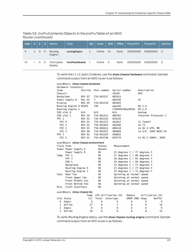
Table 53: JnxFruContents Objects in the jnxFruTable of anM20Router (continued)
UptimePowerOnPowerOffOfflineTempStateSlotTypeNameL3L2L1Index
00:0:00:00.000:0:00:00.00None24Online2routingEngineRoutingEngine 1
0029
00:0:00:00.000:0:00:00.00None0Online1frontPanelModuleFront paneldisplay
00110
To verify the L1, L2, and L3 indexes, use the show chassis hardware command. Sample
command output from an M20 router is as follows:
user@host> show chassis hardwareHardware inventory:Item Version Part number Serial number DescriptionChassis 20200 M20Backplane REV 07 710-001517 AB5911Power Supply B Rev 02 7 000240 ACDisplay REV 04 710-001519 AD1903Routing Engine 0 REV01 740 umeshk RE-2.0Routing Engine 1 270000078ba48501 RE-2.0SSB slot 0 N/A N/A N/A backupSSB slot 1 REV 04 710-001411 AD0281 Internet Processor IFPC 1 REV 01 710-001292 AC9230 PIC 0 REV 01 750-001323 AA2812 1x Tunnel PIC 1 REV 01 750-002963 AK8586 4x T3 PIC 2 REV 03 750-000612 AM8116 2x OC-3 ATM, MM PIC 3 REV 08 750-001072 AB9884 1x G/E, 1000 BASE-SXFPC 3 REV 01 710-001197 AA8661 PIC 2 REV 01 750-003748 HE9734 2x OC-3 SONET, SMIR
user@host> show chassis environmentClass Item Status MeasurementPower Power Supply A Absent Power Supply B OK 25 degrees C / 77 degrees FTemp FPC 1 OK 27 degrees C / 80 degrees F FPC 3 OK 28 degrees C / 82 degrees F SSB 1 OK 29 degrees C / 84 degrees F Backplane OK 23 degrees C / 73 degrees F Routing Engine 0 OK 25 degrees C / 77 degrees F Routing Engine 1 OK 24 degrees C / 75 degrees FFans Rear Fan OK Spinning at normal speed Front Upper Fan OK Spinning at normal speed Front Middle Fan OK Spinning at normal speed Front Bottom Fan OK Spinning at normal speedMisc Craft Interface OK
user@host> show chassis fpc Temp CPU Utilization (%) Memory Utilization (%)Slot State (C) Total Interrupt DRAM (MB) Heap Buffer 0 Empty 0 0 0 0 0 0 1 Online 27 8 7 8 9 14 2 Empty 0 0 0 0 0 0 3 Online 28 0 0 8 8 14
To verify Routing Engine status, use the show chassis routing-engine command. Sample
command output from an M10 router is as follows:
231Copyright © 2010, Juniper Networks, Inc.
Chapter 15: Interpreting the Enterprise-Specific Chassis MIBs
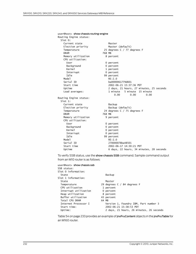
user@host> show chassis routing-engineRouting Engine status: Slot 0: Current state Master Election priority Master (default) Temperature 25 degrees C / 77 degrees F DRAM 768 MB Memory utilization 8 percent CPU utilization: User 0 percent Background 0 percent Kernel 1 percent Interrupt 0 percent Idle 99 percent Model RE-2.0 Serial ID ba0000061779d601 Start time 2002-06-21 15:37:36 PDT Uptime 2 days, 21 hours, 27 minutes, 25 seconds Load averages: 1 minute 5 minute 15 minute 0.00 0.00 0.00Routing Engine status: Slot 1: Current state Backup Election priority Backup (default) Temperature 24 degrees C / 75 degrees F DRAM 768 MB Memory utilization 9 percent CPU utilization: User 0 percent Background 0 percent Kernel 0 percent Interrupt 0 percent Idle 99 percent Model RE-2.0 Serial ID 270000078ba48501 Start time 2002-06-17 14:30:21 PDT Uptime 6 days, 22 hours, 34 minutes, 28 seconds
To verify SSB status, use the show chassis SSB command. Sample command output
from an M10 router is as follows:
user@host> show chassis ssbSSB status:Slot 0 information: State BackupSlot 1 information: State Master Temperature 29 degrees C / 84 degrees F CPU utilization 1 percent Interrupt utilization 0 percent Heap utilization 8 percent Buffer utilization 43 percent Total CPU DRAM 64 MB Internet Processor I Version 1, Foundry IBM, Part number 3 Start time: 2002-06-21 15:38:53 PDT Uptime: 2 days, 21 hours, 26 minutes, 26 seconds
Table 54 on page 233 provides an example of jnxFruContentobjects in the jnxFruTable for
an M160 router.
Copyright © 2010, Juniper Networks, Inc.232
SRX100, SRX210, SRX220, SRX240, and SRX650 Services Gateways MIB Reference
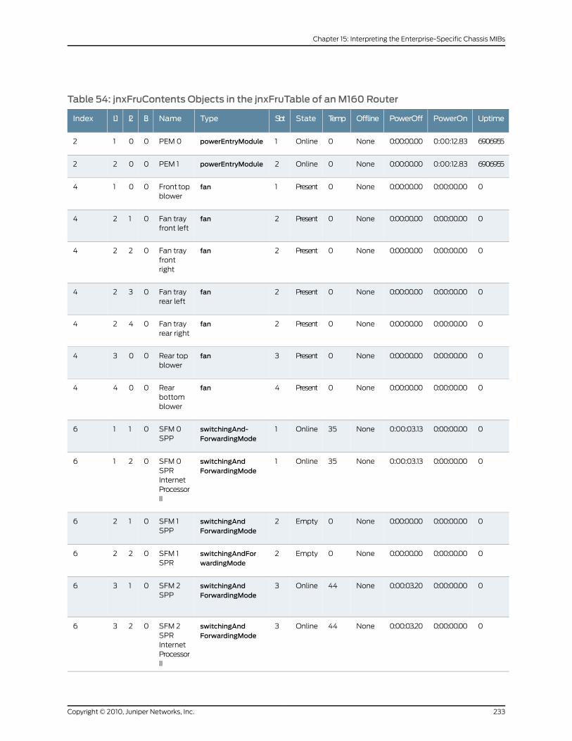
Table 54: jnxFruContents Objects in the jnxFruTable of anM160 Router
UptimePowerOnPowerOffOfflineTempStateSlotTypeNameL3L2L1Index
69069550:00:12.830:00:00.00None0Online1powerEntryModulePEM 00012
69069550:00:12.830:00:00.00None0Online2powerEntryModulePEM 10022
00:00:00.000:00:00.00None0Present1fanFront topblower
0014
00:00:00.000:00:00.00None0Present2fanFan trayfront left
0124
00:00:00.000:00:00.00None0Present2fanFan trayfrontright
0224
00:00:00.000:00:00.00None0Present2fanFan trayrear left
0324
00:00:00.000:00:00.00None0Present2fanFan trayrear right
0424
00:00:00.000:00:00.00None0Present3fanRear topblower
0034
00:00:00.000:00:00.00None0Present4fanRearbottomblower
0044
00:00:00.000:00:03.13None35Online1switchingAnd-ForwardingMode
SFM 0SPP
0116
00:00:00.000:00:03.13None35Online1switchingAndForwardingMode
SFM 0SPRInternetProcessorII
0216
00:00:00.000:00:00.00None0Empty2switchingAndForwardingMode
SFM 1SPP
0126
00:00:00.000:00:00.00None0Empty2switchingAndForwardingMode
SFM 1SPR
0226
00:00:00.000:00:03.20None44Online3switchingAndForwardingMode
SFM 2SPP
0136
00:00:00.000:00:03.20None44Online3switchingAndForwardingMode
SFM 2SPRInternetProcessorII
0236
233Copyright © 2010, Juniper Networks, Inc.
Chapter 15: Interpreting the Enterprise-Specific Chassis MIBs
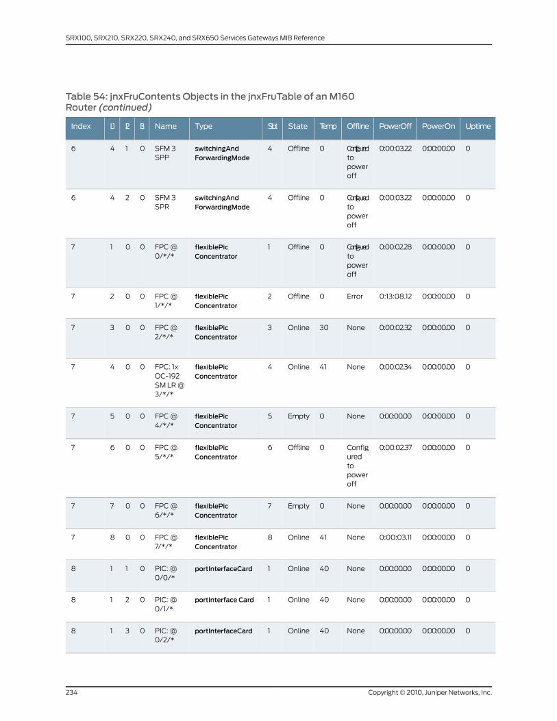
Table 54: jnxFruContents Objects in the jnxFruTable of anM160Router (continued)
UptimePowerOnPowerOffOfflineTempStateSlotTypeNameL3L2L1Index
00:00:00.000:00:03.22Config-uredtopoweroff
0Offline4switchingAndForwardingMode
SFM 3SPP
0146
00:00:00.000:00:03.22Config-uredtopoweroff
0Offline4switchingAndForwardingMode
SFM 3SPR
0246
00:00:00.000:00:02.28Config-uredtopoweroff
0Offline1flexiblePicConcentrator
FPC @0/*/*
0017
00:00:00.000:13:08.12Error0Offline2flexiblePicConcentrator
FPC @1/*/*
0027
00:00:00.000:00:02.32None30Online3flexiblePicConcentrator
FPC @2/*/*
0037
00:00:00.000:00:02.34None41Online4flexiblePicConcentrator
FPC: 1xOC-192SM LR @3/*/*
0047
00:00:00.000:00:00.00None0Empty5flexiblePicConcentrator
FPC @4/*/*
0057
00:00:00.000:00:02.37Configuredtopoweroff
0Offline6flexiblePicConcentrator
FPC @5/*/*
0067
00:00:00.000:00:00.00None0Empty7flexiblePicConcentrator
FPC @6/*/*
0077
00:00:00.000:00:03.11None41Online8flexiblePicConcentrator
FPC @7/*/*
0087
00:00:00.000:00:00.00None40Online1portInterfaceCardPIC: @0/0/*
0118
00:00:00.000:00:00.00None40Online1portInterface CardPIC: @0/1/*
0218
00:00:00.000:00:00.00None40Online1portInterfaceCardPIC: @0/2/*
0318
Copyright © 2010, Juniper Networks, Inc.234
SRX100, SRX210, SRX220, SRX240, and SRX650 Services Gateways MIB Reference
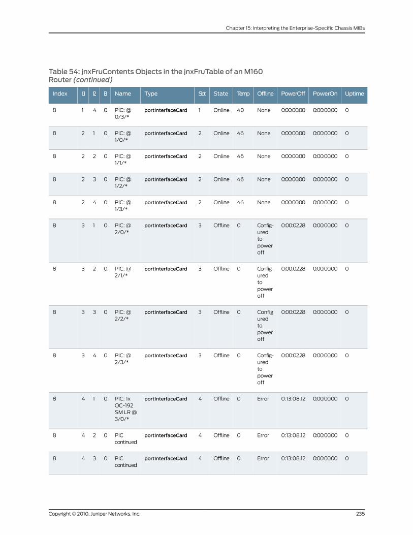
Table 54: jnxFruContents Objects in the jnxFruTable of anM160Router (continued)
UptimePowerOnPowerOffOfflineTempStateSlotTypeNameL3L2L1Index
00:00:00.000:00:00.00None40Online1portInterfaceCardPIC: @0/3/*
0418
00:00:00.000:00:00.00None46Online2portInterfaceCardPIC: @1/0/*
0128
00:00:00.000:00:00.00None46Online2portInterfaceCardPIC: @1/1/*
0228
00:00:00.000:00:00.00None46Online2portInterfaceCardPIC: @1/2/*
0328
00:00:00.000:00:00.00None46Online2portInterfaceCardPIC: @1/3/*
0428
00:00:00.000:00:02.28Config-uredtopoweroff
0Offline3portInterfaceCardPIC: @2/0/*
0138
00:00:00.000:00:02.28Config-uredtopoweroff
0Offline3portInterfaceCardPIC: @2/1/*
0238
00:00:00.000:00:02.28Configuredtopoweroff
0Offline3portInterfaceCardPIC: @2/2/*
0338
00:00:00.000:00:02.28Config-uredtopoweroff
0Offline3portInterfaceCardPIC: @2/3/*
0438
00:00:00.000:13:08.12Error0Offline4portInterfaceCardPIC: 1xOC-192SM LR @3/0/*
0148
00:00:00.000:13:08.12Error0Offline4portInterfaceCardPICcontinued
0248
00:00:00.000:13:08.12Error0Offline4portInterfaceCardPICcontinued
0348
235Copyright © 2010, Juniper Networks, Inc.
Chapter 15: Interpreting the Enterprise-Specific Chassis MIBs
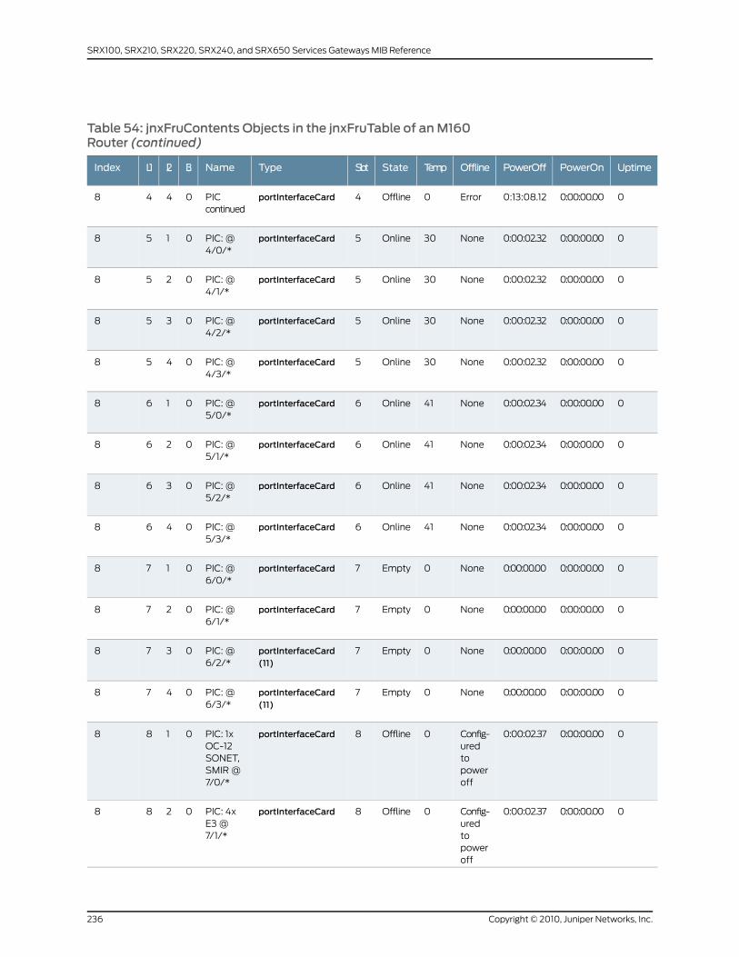
Table 54: jnxFruContents Objects in the jnxFruTable of anM160Router (continued)
UptimePowerOnPowerOffOfflineTempStateSlotTypeNameL3L2L1Index
00:00:00.000:13:08.12Error0Offline4portInterfaceCardPICcontinued
0448
00:00:00.000:00:02.32None30Online5portInterfaceCardPIC: @4/0/*
0158
00:00:00.000:00:02.32None30Online5portInterfaceCardPIC: @4/1/*
0258
00:00:00.000:00:02.32None30Online5portInterfaceCardPIC: @4/2/*
0358
00:00:00.000:00:02.32None30Online5portInterfaceCardPIC: @4/3/*
0458
00:00:00.000:00:02.34None41Online6portInterfaceCardPIC: @5/0/*
0168
00:00:00.000:00:02.34None41Online6portInterfaceCardPIC: @5/1/*
0268
00:00:00.000:00:02.34None41Online6portInterfaceCardPIC: @5/2/*
0368
00:00:00.000:00:02.34None41Online6portInterfaceCardPIC: @5/3/*
0468
00:00:00.000:00:00.00None0Empty7portInterfaceCardPIC: @6/0/*
0178
00:00:00.000:00:00.00None0Empty7portInterfaceCardPIC: @6/1/*
0278
00:00:00.000:00:00.00None0Empty7portInterfaceCard(11)
PIC: @6/2/*
0378
00:00:00.000:00:00.00None0Empty7portInterfaceCard(11)
PIC: @6/3/*
0478
00:00:00.000:00:02.37Config-uredtopoweroff
0Offline8portInterfaceCardPIC: 1xOC-12SONET,SMIR @7/0/*
0188
00:00:00.000:00:02.37Config-uredtopoweroff
0Offline8portInterfaceCardPIC: 4xE3 @7/1/*
0288
Copyright © 2010, Juniper Networks, Inc.236
SRX100, SRX210, SRX220, SRX240, and SRX650 Services Gateways MIB Reference
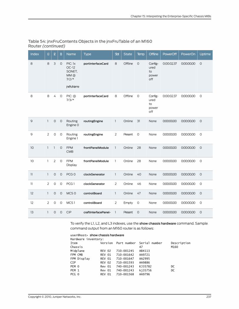
Table 54: jnxFruContents Objects in the jnxFruTable of anM160Router (continued)
UptimePowerOnPowerOffOfflineTempStateSlotTypeNameL3L2L1Index
00:00:00.000:00:02.37Config-uredtopoweroff
0Offline8portInterfaceCardPIC: 1xOC-12SONET,MM @7/2/*
jnxFruName
0388
00:00:00.000:00:02.37Config-uredtopoweroff
0Offline8portInterfaceCardPIC: @7/3/*
0488
00:00:00.000:00:00.00None31Online1routingEngineRoutingEngine 0
0019
00:00:00.000:00:00.00None0Present2routingEngineRoutingEngine 1
0029
00:00:00.000:00:00.00None28Online1frontPanelModuleFPMCMB
01110
00:00:00.000:00:00.00None28Online1frontPanelModuleFPMDisplay
02110
00:00:00.000:00:00.00None40Online1clockGeneratorPCG 000111
00:00:00.000:00:00.00None46Online2clockGeneratorPCG 100211
00:00:00.000:00:00.00None47Online1controlBoardMCS 000112
00:00:00.000:00:00.00None0Empty2controlBoardMCS 100212
00:00:00.000:00:00.00None0Present1craftInterfacePanel-CIP00113
To verify the L1, L2, and L3 indexes, use the show chassis hardware command. Sample
command output from an M160 router is as follows:
user@host> show chassis hardwareHardware inventory:Item Version Part number Serial number DescriptionChassis 47 M160Midplane REV 02 710-001245 AB4113FPM CMB REV 01 710-001642 AA9721FPM Display REV 01 710-001647 AA2995CIP REV 02 710-001593 AA9886PEM 0 Rev 01 740-001243 KJ35782 DCPEM 1 Rev 01 740-001243 kj35756 DCPCG 0 REV 01 710-001568 AA9796
237Copyright © 2010, Juniper Networks, Inc.
Chapter 15: Interpreting the Enterprise-Specific Chassis MIBs
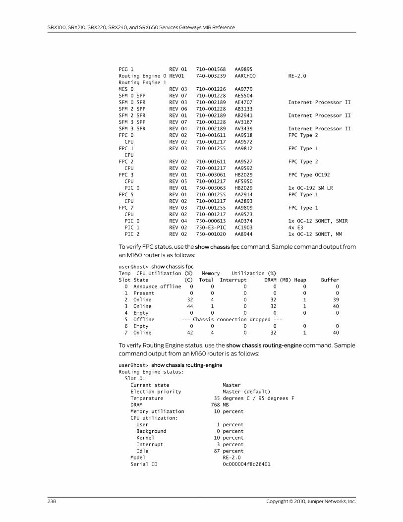
PCG 1 REV 01 710-001568 AA9895Routing Engine 0 REV01 740-003239 AARCHOO RE-2.0Routing Engine 1MCS 0 REV 03 710-001226 AA9779SFM 0 SPP REV 07 710-001228 AE5504SFM 0 SPR REV 03 710-002189 AE4707 Internet Processor IISFM 2 SPP REV 06 710-001228 AB3133SFM 2 SPR REV 01 710-002189 AB2941 Internet Processor IISFM 3 SPP REV 07 710-001228 AV3167SFM 3 SPR REV 04 710-002189 AV3439 Internet Processor IIFPC 0 REV 02 710-001611 AA9518 FPC Type 2 CPU REV 02 710-001217 AA9572FPC 1 REV 03 710-001255 AA9812 FPC Type 1 CPUFPC 2 REV 02 710-001611 AA9527 FPC Type 2 CPU REV 02 710-001217 AA9592FPC 3 REV 01 710-003061 HB2029 FPC Type OC192 CPU REV 05 710-001217 AF5950 PIC 0 REV 01 750-003063 HB2029 1x OC-192 SM LRFPC 5 REV 01 710-001255 AA2914 FPC Type 1 CPU REV 02 710-001217 AA2893FPC 7 REV 03 710-001255 AA9809 FPC Type 1 CPU REV 02 710-001217 AA9573 PIC 0 REV 04 750-000613 AA0374 1x OC-12 SONET, SMIR PIC 1 REV 02 750-E3-PIC AC1903 4x E3 PIC 2 REV 02 750-001020 AA8944 1x OC-12 SONET, MM
To verify FPC status, use the showchassis fpc command. Sample command output from
an M160 router is as follows:
user@host> show chassis fpcTemp CPU Utilization (%) Memory Utilization (%)Slot State (C) Total Interrupt DRAM (MB) Heap Buffer 0 Announce offline 0 0 0 0 0 0 1 Present 0 0 0 0 0 0 2 Online 32 4 0 32 1 39 3 Online 44 1 0 32 1 40 4 Empty 0 0 0 0 0 0 5 Offline --- Chassis connection dropped --- 6 Empty 0 0 0 0 0 0 7 Online 42 4 0 32 1 40
To verify Routing Engine status, use the show chassis routing-engine command. Sample
command output from an M160 router is as follows:
user@host> show chassis routing-engineRouting Engine status: Slot 0: Current state Master Election priority Master (default) Temperature 35 degrees C / 95 degrees F DRAM 768 MB Memory utilization 10 percent CPU utilization: User 1 percent Background 0 percent Kernel 10 percent Interrupt 3 percent Idle 87 percent Model RE-2.0 Serial ID 0c000004f8d26401
Copyright © 2010, Juniper Networks, Inc.238
SRX100, SRX210, SRX220, SRX240, and SRX650 Services Gateways MIB Reference
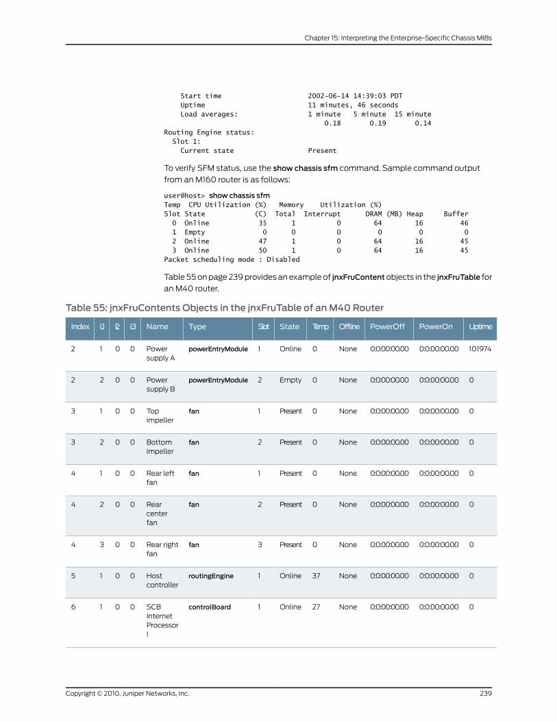
Start time 2002-06-14 14:39:03 PDT Uptime 11 minutes, 46 seconds Load averages: 1 minute 5 minute 15 minute 0.18 0.19 0.14Routing Engine status: Slot 1: Current state Present
To verify SFM status, use the show chassis sfm command. Sample command output
from an M160 router is as follows:
user@host> show chassis sfmTemp CPU Utilization (%) Memory Utilization (%)Slot State (C) Total Interrupt DRAM (MB) Heap Buffer 0 Online 35 1 0 64 16 46 1 Empty 0 0 0 0 0 0 2 Online 47 1 0 64 16 45 3 Online 50 1 0 64 16 45Packet scheduling mode : Disabled
Table 55 on page 239 provides an example of jnxFruContentobjects in the jnxFruTable for
an M40 router.
Table 55: jnxFruContents Objects in the jnxFruTable of anM40 Router
UptimePowerOnPowerOffOfflineTempStateSlotTypeNameL3L2L1Index
1019740:0:00:00.000:0:00:00.00None0Online1powerEntryModulePowersupply A
0012
00:0:00:00.000:0:00:00.00None0Empty2powerEntryModulePowersupply B
0022
00:0:00:00.000:0:00:00.00None0Present1fanTopimpeller
0013
00:0:00:00.000:0:00:00.00None0Present2fanBottomimpeller
0023
00:0:00:00.000:0:00:00.00None0Present1fanRear leftfan
0014
00:0:00:00.000:0:00:00.00None0Present2fanRearcenterfan
0024
00:0:00:00.000:0:00:00.00None0Present3fanRear rightfan
0034
00:0:00:00.000:0:00:00.00None37Online1routingEngineHostcontroller
0015
00:0:00:00.000:0:00:00.00None27Online1controlBoardSCBInternetProcessorI
0016
239Copyright © 2010, Juniper Networks, Inc.
Chapter 15: Interpreting the Enterprise-Specific Chassis MIBs
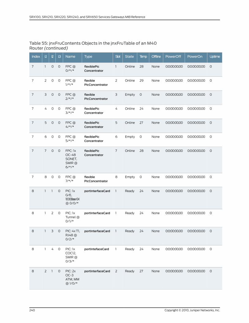
Table 55: jnxFruContents Objects in the jnxFruTable of anM40Router (continued)
UptimePowerOnPowerOffOfflineTempStateSlotTypeNameL3L2L1Index
00:0:00:00.000:0:00:00.00None28Online1flexiblePicConcentrator
FPC @0/*/*
0017
00:0:00:00.000:0:00:00.00None29Online2flexiblePicConcentrator
FPC @1/*/*
0027
00:0:00:00.000:0:00:00.00None0Empty3flexiblePicConcentrator
FPC @2/*/*
0037
00:0:00:00.000:0:00:00.00None24Online4flexiblePicConcentrator
FPC @3/*/*
0047
00:0:00:00.000:0:00:00.00None27Online5flexiblePicConcentrator
FPC @4/*/*
0057
00:0:00:00.000:0:00:00.00None0Empty6flexiblePicConcentrator
FPC @5/*/*
0067
00:0:00:00.000:0:00:00.00None28Online7flexiblePicConcentrator
FPC: 1xOC-48SONET,SMIR @6/*/*
0077
00:0:00:00.000:0:00:00.00None0Empty8flexiblePicConcentrator
FPC @7/*/*
0087
00:0:00:00.000:0:00:00.00None24Ready1portInterfaceCardPIC: 1xG/E,1000Base-SX@ 0/0/*
0118
00:0:00:00.000:0:00:00.00None24Ready1portInterfaceCardPIC: 1xTunnel @0/1/*
0218
00:0:00:00.000:0:00:00.00None24Ready1portInterfaceCardPIC: 4x T1,RJ48 @0/2/*
0318
00:0:00:00.000:0:00:00.00None24Ready1portIntefaceCardPIC: 1xCOC12,SMIR @0/3/*
0418
00:0:00:00.000:0:00:00.00None27Ready2portInterfaceCardPIC: 2xOC-3ATM, MM@ 1/0/*
0128
Copyright © 2010, Juniper Networks, Inc.240
SRX100, SRX210, SRX220, SRX240, and SRX650 Services Gateways MIB Reference
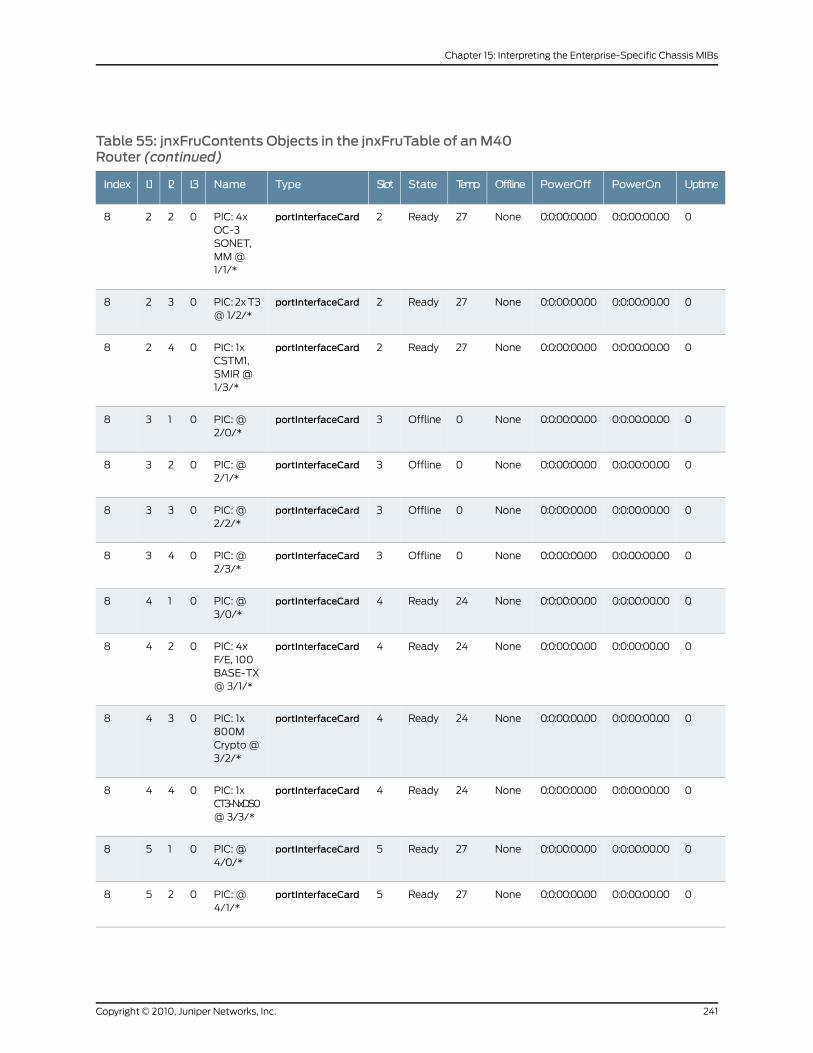
Table 55: jnxFruContents Objects in the jnxFruTable of anM40Router (continued)
UptimePowerOnPowerOffOfflineTempStateSlotTypeNameL3L2L1Index
00:0:00:00.000:0:00:00.00None27Ready2portInterfaceCardPIC: 4xOC-3SONET,MM @1/1/*
0228
00:0:00:00.000:0:00:00.00None27Ready2portInterfaceCardPIC: 2x T3@ 1/2/*
0328
00:0:00:00.000:0:00:00.00None27Ready2portInterfaceCardPIC: 1xCSTM1,SMIR @1/3/*
0428
00:0:00:00.000:0:00:00.00None0Offline3portInterfaceCardPIC: @2/0/*
0138
00:0:00:00.000:0:00:00.00None0Offline3portInterfaceCardPIC: @2/1/*
0238
00:0:00:00.000:0:00:00.00None0Offline3portInterfaceCardPIC: @2/2/*
0338
00:0:00:00.000:0:00:00.00None0Offline3portInterfaceCardPIC: @2/3/*
0438
00:0:00:00.000:0:00:00.00None24Ready4portInterfaceCardPIC: @3/0/*
0148
00:0:00:00.000:0:00:00.00None24Ready4portInterfaceCardPIC: 4xF/E, 100BASE-TX@ 3/1/*
0248
00:0:00:00.000:0:00:00.00None24Ready4portInterfaceCardPIC: 1x800MCrypto @3/2/*
0348
00:0:00:00.000:0:00:00.00None24Ready4portInterfaceCardPIC: 1xCT3-NxDS0@ 3/3/*
0448
00:0:00:00.000:0:00:00.00None27Ready5portInterfaceCardPIC: @4/0/*
0158
00:0:00:00.000:0:00:00.00None27Ready5portInterfaceCardPIC: @4/1/*
0258
241Copyright © 2010, Juniper Networks, Inc.
Chapter 15: Interpreting the Enterprise-Specific Chassis MIBs
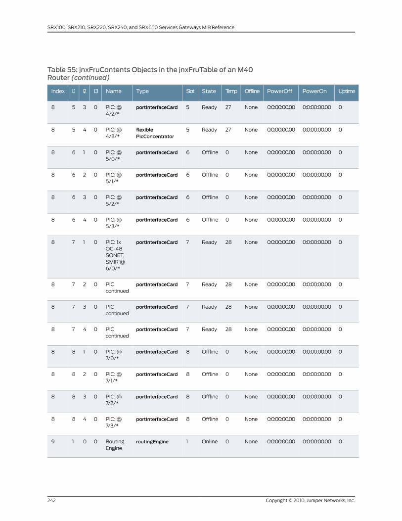
Table 55: jnxFruContents Objects in the jnxFruTable of anM40Router (continued)
UptimePowerOnPowerOffOfflineTempStateSlotTypeNameL3L2L1Index
00:0:00:00.000:0:00:00.00None27Ready5portInterfaceCardPIC: @4/2/*
0358
00:0:00:00.000:0:00:00.00None27Ready5flexiblePicConcentrator
PIC: @4/3/*
0458
00:0:00:00.000:0:00:00.00None0Offline6portInterfaceCardPIC: @5/0/*
0168
00:0:00:00.000:0:00:00.00None0Offline6portInterfaceCardPIC: @5/1/*
0268
00:0:00:00.000:0:00:00.00None0Offline6portInterfaceCardPIC: @5/2/*
0368
00:0:00:00.000:0:00:00.00None0Offline6portInterfaceCardPIC: @5/3/*
0468
00:0:00:00.000:0:00:00.00None28Ready7portInterfaceCardPIC: 1xOC-48SONET,SMIR @6/0/*
0178
00:0:00:00.000:0:00:00.00None28Ready7portInterfaceCardPICcontinued
0278
00:0:00:00.000:0:00:00.00None28Ready7portInterfaceCardPICcontinued
0378
00:0:00:00.000:0:00:00.00None28Ready7portInterfaceCardPICcontinued
0478
00:0:00:00.000:0:00:00.00None0Offline8portInterfaceCardPIC: @7/0/*
0188
00:0:00:00.000:0:00:00.00None0Offline8portInterfaceCardPIC: @7/1/*
0288
00:0:00:00.000:0:00:00.00None0Offline8portInterfaceCardPIC: @7/2/*
0388
00:0:00:00.000:0:00:00.00None0Offline8portInterfaceCardPIC: @7/3/*
0488
00:0:00:00.000:0:00:00.00None0Online1routingEngineRoutingEngine
0019
Copyright © 2010, Juniper Networks, Inc.242
SRX100, SRX210, SRX220, SRX240, and SRX650 Services Gateways MIB Reference

To verify the L1, L2, and L3 indexes, use the show chassis hardware command. Sample
command output from an M40 router is as follows:
user@host> show chassis hardwareHardware inventory:Item Version Part number Serial number DescriptionChassisBackplane REV 03 710-000073 AA2005Power Supply A Rev A 740-000235 000119 DCMaxicab REV 04 710-000229 AA0691Minicab REV 02 710-000482 AA0270Display REV 06 710-000150 AA1042Routing Engine RE-1.0SCB REV 07 710-000075 AA1033 Internet Processor IFPC 0 REV 01 710-001292 AB8159 PIC 0 REV 08 750-001072 AP5525 1x G/E, 1000 BASE-SX PIC 1 REV 01 750-001323 AB1645 1x Tunnel PIC 2 REV 01 750-002953 AD9083 4x T1, RJ48 PIC 3 REV 03 750-001190 AE2907 1x COC12, SMIRFPC 1 REV 10 710-000175 AA7219 PIC 0 REV 03 750-002977 HD9331 2x OC-3 ATM, MM PIC 1 REV 04 750-002971 HC8020 4x OC-3 SONET, MM PIC 2 REV 02.1 710-000608 AA1592 2x T3 PIC 3 REV 05 750-003248 AD9648 1x CSTM1, SMIRFPC 3 REV 10 710-000175 AA4782 PIC 1 REV 04 750-002992 HC3974 4x F/E, 100 BASE-TX PIC 2 REV 03 750-003844 AY4806 1x 800M Crypto PIC 3 REV 03 750-004743 BD9433 1x CT3-NxDS0FPC 4 REV 01 710-001292 AC5265FPC 6 REV 01 710-001292 AB7485 PIC 0 REV 03 750-000617 AA4566 1x OC-48 SONET, SMIR
user@host> show chassis environmentClass Item Status MeasurementPower Power Supply A OK Power Supply B AbsentTemp FPC 0 OK 28 degrees C / 82 degrees F FPC 1 OK 29 degrees C / 84 degrees F FPC 3 OK 24 degrees C / 75 degrees F FPC 4 OK 27 degrees C / 80 degrees F FPC 6 OK 28 degrees C / 82 degrees F SCB OK 27 degrees C / 80 degrees F Backplane @ A1 OK 30 degrees C / 86 degrees F Backplane @ A2 OK 26 degrees C / 78 degrees F Routing Engine OK 37 degrees C / 98 degrees FFans Top Impeller OK Spinning at normal speed Bottom impeller OK Spinning at normal speed Rear Left Fan OK Spinning at normal speed Rear Center Fan OK Spinning at normal speed Rear Right Fan OK Spinning at normal speedMisc Craft Interface OK
To verify FPC status, use the showchassis fpc command. Sample command output from
an M40 router is as follows:
user@host> show chassis fpcTemp CPU Utilization (%) Memory Utilization (%)Slot State (C) Total Interrupt DRAM (MB) Heap Buffer 0 Online 28 2 0 8 11 14 1 Online 29 7 0 8 21 14 2 Empty 0 0 0 0 0 0
243Copyright © 2010, Juniper Networks, Inc.
Chapter 15: Interpreting the Enterprise-Specific Chassis MIBs
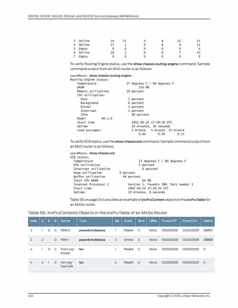
3 Online 24 17 0 8 22 15 4 Online 27 1 0 8 6 13 5 Empty 0 0 0 0 0 0 6 Online 28 1 0 8 7 15 7 Empty 0 0 0 0 0 0
To verify Routing Engine status, use the show chassis routing-engine command. Sample
command output from an M40 router is as follows:
user@host> show chassis routing-engineRouting Engine status: Temperature 37 degrees C / 98 degrees F DRAM 256 MB Memory utilization 19 percent CPU utilization: User 1 percent Background 0 percent Kernel 3 percent Interrupt 1 percent Idle 96 percent Model RE-1.0 Start time 2002-06-24 17:28:30 UTC Uptime 20 minutes, 30 seconds Load averages: 1 minute 5 minute 15 minute 0.00 0.04 0.11
To verify SCB status, use the showchassis scb command. Sample command output from
an M40 router is as follows:
user@host> show chassis scbSCB status: Temperature 27 degrees C / 80 degrees F CPU utilization 3 percent Interrupt utilization 0 percent Heap utilization 9 percent Buffer utilization 44 percent Total CPU DRAM 64 MB Internet Processor I Version 1, Foundry IBM, Part number 3 Start time: 2002-06-24 17:30:10 UTC Uptime: 19 minutes, 8 seconds
Table 56 on page 244 provides an example of jnxFruContentobjects in the jnxFruTable for
an M40e router.
Table 56: JnxFruContents Objects in the jnxFruTable of anM40e Router
UptimePowerOnPowerOffOfflineTempStateSlotTypeNameL3L2L1Index
2089270:0:00:25.990:0:00:00.00None0Present1powerEntryModulePEM 00012
2089280:0:00:25.990:0:00:00.00None0Online2powerEntryModulePEM 1022
00:0:00:00.000:0:00:00.00None0Present1fanFront topblower
0014
00:0:00:00.000:0:00:00.00None0Present2fanFan trayfront left
0124
Copyright © 2010, Juniper Networks, Inc.244
SRX100, SRX210, SRX220, SRX240, and SRX650 Services Gateways MIB Reference
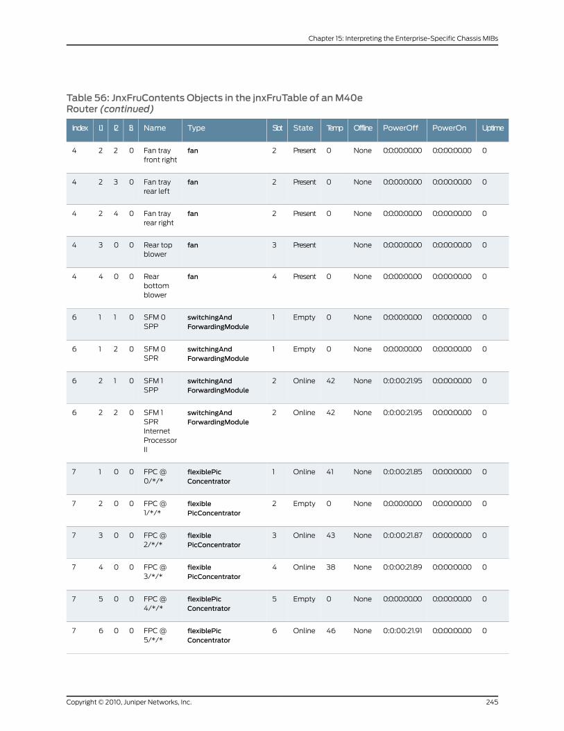
Table 56: JnxFruContents Objects in the jnxFruTable of anM40eRouter (continued)
UptimePowerOnPowerOffOfflineTempStateSlotTypeNameL3L2L1Index
00:0:00:00.000:0:00:00.00None0Present2fanFan trayfront right
0224
00:0:00:00.000:0:00:00.00None0Present2fanFan trayrear left
0324
00:0:00:00.000:0:00:00.00None0Present2fanFan trayrear right
0424
00:0:00:00.000:0:00:00.00NonePresent3fanRear topblower
0034
00:0:00:00.000:0:00:00.00None0Present4fanRearbottomblower
0044
00:0:00:00.000:0:00:00.00None0Empty1switchingAndForwardingModule
SFM 0SPP
0116
00:0:00:00.000:0:00:00.00None0Empty1switchingAndForwardingModule
SFM 0SPR
0216
00:0:00:00.000:0:00:21.95None42Online2switchingAndForwardingModule
SFM 1SPP
0126
00:0:00:00.000:0:00:21.95None42Online2switchingAndForwardingModule
SFM 1SPRInternetProcessorII
0226
00:0:00:00.000:0:00:21.85None41Online1flexiblePicConcentrator
FPC @0/*/*
0017
00:0:00:00.000:0:00:00.00None0Empty2flexiblePicConcentrator
FPC @1/*/*
0027
00:0:00:00.000:0:00:21.87None43Online3flexiblePicConcentrator
FPC @2/*/*
0037
00:0:00:00.000:0:00:21.89None38Online4flexiblePicConcentrator
FPC @3/*/*
0047
00:0:00:00.000:0:00:00.00None0Empty5flexiblePicConcentrator
FPC @4/*/*
0057
00:0:00:00.000:0:00:21.91None46Online6flexiblePicConcentrator
FPC @5/*/*
0067
245Copyright © 2010, Juniper Networks, Inc.
Chapter 15: Interpreting the Enterprise-Specific Chassis MIBs
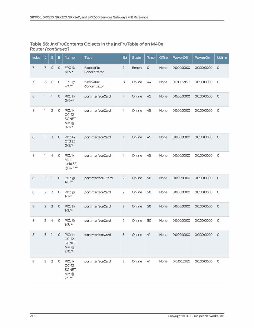
Table 56: JnxFruContents Objects in the jnxFruTable of anM40eRouter (continued)
UptimePowerOnPowerOffOfflineTempStateSlotTypeNameL3L2L1Index
00:0:00:00.000:0:00:00.00None0Empty7flexiblePicConcentrator
FPC @6/*/*
0077
00:0:00:00.000:0:00:21.93None44Online8flexiblePicConcentrator
FPC @7/*/*
0087
00:0:00:00.000:0:00:00.00None45Online1portInterfaceCardPIC: @0/0/*
0118
00:0:00:00.000:0:00:00.00None45Online1portInterfaceCardPIC: 1xOC-12SONET,MM @0/1/*
0218
00:0:00:00.000:0:00:00.00None45Online1portInterfaceCardPIC: 4xCT3 @0/2/*
0318
00:0:00:00.000:0:00:00.00None45Online1portInterfaceCardPIC: 1xMultiLink(32)@ 0/3/*
0418
00:0:00:00.000:0:00:00.00None50Online2portInterface- CardPIC: @1/0/*
0128
00:0:00:00.000:0:00:00.00None50Online2portInterfaceCardPIC: @1/1/*
0228
00:0:00:00.000:0:00:00.00None50Online2portInterfaceCardPIC: @1/2/*
0328
00:0:00:00.000:0:00:00.00None50Online2portInterfaceCardPIC: @1/3/*
0428
00:0:00:00.000:0:00:00.00None41Online3portInterfaceCardPIC: 1xOC-12SONET,MM @2/0/*
0138
00:0:00:00.000:0:00:21.85None41Online3portInterfaceCardPIC: 1xOC-12SONET,MM @2/1/*
0238
Copyright © 2010, Juniper Networks, Inc.246
SRX100, SRX210, SRX220, SRX240, and SRX650 Services Gateways MIB Reference
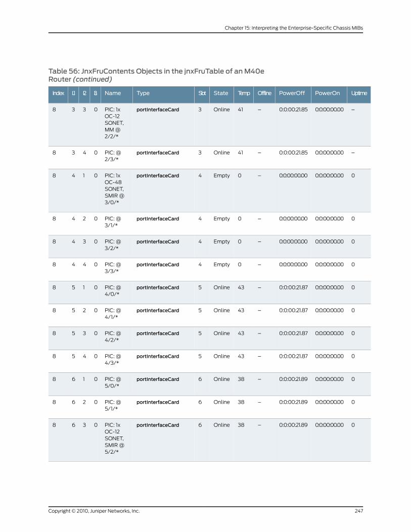
Table 56: JnxFruContents Objects in the jnxFruTable of anM40eRouter (continued)
UptimePowerOnPowerOffOfflineTempStateSlotTypeNameL3L2L1Index
–0:0:00:00.000:0:00:21.85–41Online3portInterfaceCardPIC: 1xOC-12SONET,MM @2/2/*
0338
–0:0:00:00.000:0:00:21.85–41Online3portInterfaceCardPIC: @2/3/*
0438
00:0:00:00.000:0:00:00.00–0Empty4portInterfaceCardPIC: 1xOC-48SONET,SMIR @3/0/*
0148
00:0:00:00.000:0:00:00.00–0Empty4portInterfaceCardPIC: @3/1/*
0248
00:0:00:00.000:0:00:00.00–0Empty4portInterfaceCardPIC: @3/2/*
0348
00:0:00:00.000:0:00:00.00–0Empty4portInterfaceCardPIC: @3/3/*
0448
00:0:00:00.000:0:00:21.87–43Online5portInterfaceCardPIC: @4/0/*
0158
00:0:00:00.000:0:00:21.87–43Online5portInterfaceCardPIC: @4/1/*
0258
00:0:00:00.000:0:00:21.87–43Online5portInterfaceCardPIC: @4/2/*
0358
00:0:00:00.000:0:00:21.87–43Online5portInterfaceCardPIC: @4/3/*
0458
00:0:00:00.000:0:00:21.89–38Online6portInterfaceCardPIC: @5/0/*
0168
00:0:00:00.000:0:00:21.89–38Online6portInterfaceCardPIC: @5/1/*
0268
00:0:00:00.000:0:00:21.89–38Online6portInterfaceCardPIC: 1xOC-12SONET,SMIR @5/2/*
0368
247Copyright © 2010, Juniper Networks, Inc.
Chapter 15: Interpreting the Enterprise-Specific Chassis MIBs
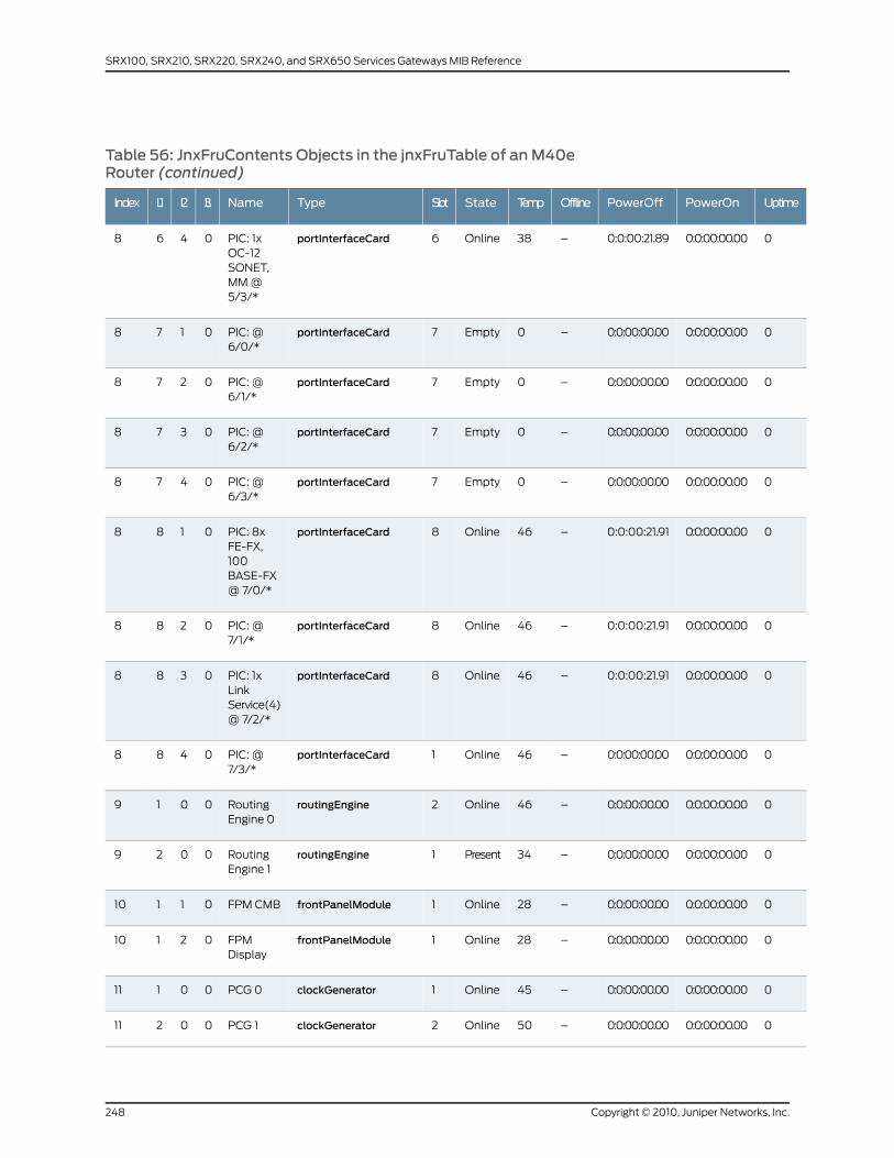
Table 56: JnxFruContents Objects in the jnxFruTable of anM40eRouter (continued)
UptimePowerOnPowerOffOfflineTempStateSlotTypeNameL3L2L1Index
00:0:00:00.000:0:00:21.89–38Online6portInterfaceCardPIC: 1xOC-12SONET,MM @5/3/*
0468
00:0:00:00.000:0:00:00.00–0Empty7portInterfaceCardPIC: @6/0/*
0178
00:0:00:00.000:0:00:00.00–0Empty7portInterfaceCardPIC: @6/1/*
0278
00:0:00:00.000:0:00:00.00–0Empty7portInterfaceCardPIC: @6/2/*
0378
00:0:00:00.000:0:00:00.00–0Empty7portInterfaceCardPIC: @6/3/*
0478
00:0:00:00.000:0:00:21.91–46Online8portInterfaceCardPIC: 8xFE-FX,100BASE-FX@ 7/0/*
0188
00:0:00:00.000:0:00:21.91–46Online8portInterfaceCardPIC: @7/1/*
0288
00:0:00:00.000:0:00:21.91–46Online8portInterfaceCardPIC: 1xLinkService(4)@ 7/2/*
0388
00:0:00:00.000:0:00:00.00–46Online1portInterfaceCardPIC: @7/3/*
0488
00:0:00:00.000:0:00:00.00–46Online2routingEngineRoutingEngine 0
0019
00:0:00:00.000:0:00:00.00–34Present1routingEngineRoutingEngine 1
0029
00:0:00:00.000:0:00:00.00–28Online1frontPanelModuleFPM CMB01110
00:0:00:00.000:0:00:00.00–28Online1frontPanelModuleFPMDisplay
02110
00:0:00:00.000:0:00:00.00–45Online1clockGeneratorPCG 000111
00:0:00:00.000:0:00:00.00–50Online2clockGeneratorPCG 100211
Copyright © 2010, Juniper Networks, Inc.248
SRX100, SRX210, SRX220, SRX240, and SRX650 Services Gateways MIB Reference
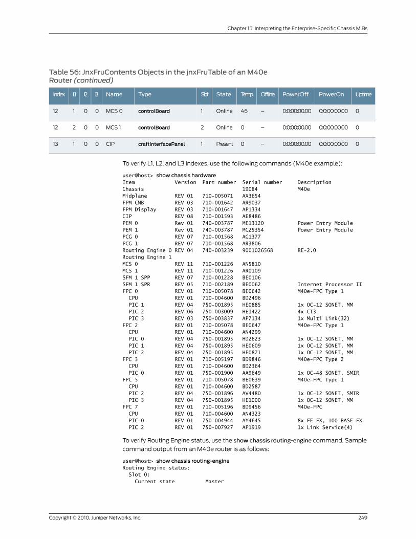
Table 56: JnxFruContents Objects in the jnxFruTable of anM40eRouter (continued)
UptimePowerOnPowerOffOfflineTempStateSlotTypeNameL3L2L1Index
00:0:00:00.000:0:00:00.00–46Online1controlBoardMCS 000112
00:0:00:00.000:0:00:00.00–0Online2controlBoardMCS 100212
00:0:00:00.000:0:00:00.00–0Present1craftInterfacePanelCIP00113
To verify L1, L2, and L3 indexes, use the following commands (M40e example):
user@host> show chassis hardwareItem Version Part number Serial number DescriptionChassis 19084 M40eMidplane REV 01 710-005071 AX3654FPM CMB REV 03 710-001642 AR9037FPM Display REV 03 710-001647 AP1334CIP REV 08 710-001593 AE8486PEM 0 Rev 01 740-003787 ME13120 Power Entry ModulePEM 1 Rev 01 740-003787 MC25354 Power Entry ModulePCG 0 REV 07 710-001568 AG1377PCG 1 REV 07 710-001568 AR3806Routing Engine 0 REV 04 740-003239 9001026568 RE-2.0Routing Engine 1MCS 0 REV 11 710-001226 AN5810MCS 1 REV 11 710-001226 AR0109SFM 1 SPP REV 07 710-001228 BE0106SFM 1 SPR REV 05 710-002189 BE0062 Internet Processor IIFPC 0 REV 01 710-005078 BE0642 M40e-FPC Type 1 CPU REV 01 710-004600 BD2496 PIC 1 REV 04 750-001895 HE0885 1x OC-12 SONET, MM PIC 2 REV 06 750-003009 HE1422 4x CT3 PIC 3 REV 03 750-003837 AP7134 1x Multi Link(32)FPC 2 REV 01 710-005078 BE0647 M40e-FPC Type 1 CPU REV 01 710-004600 AN4299 PIC 0 REV 04 750-001895 HD2623 1x OC-12 SONET, MM PIC 1 REV 04 750-001895 HE0609 1x OC-12 SONET, MM PIC 2 REV 04 750-001895 HE0871 1x OC-12 SONET, MMFPC 3 REV 01 710-005197 BD9846 M40e-FPC Type 2 CPU REV 01 710-004600 BD2364 PIC 0 REV 01 750-001900 AA9649 1x OC-48 SONET, SMIRFPC 5 REV 01 710-005078 BE0639 M40e-FPC Type 1 CPU REV 01 710-004600 BD2587 PIC 2 REV 04 750-001896 AV4480 1x OC-12 SONET, SMIR PIC 3 REV 04 750-001895 HE1000 1x OC-12 SONET, MMFPC 7 REV 01 710-005196 BD9456 M40e-FPC CPU REV 01 710-004600 AN4323 PIC 0 REV 01 750-004944 AY4645 8x FE-FX, 100 BASE-FX PIC 2 REV 01 750-007927 AP1919 1x Link Service(4)
To verify Routing Engine status, use the show chassis routing-engine command. Sample
command output from an M40e router is as follows:
user@host> show chassis routing-engineRouting Engine status: Slot 0: Current state Master
249Copyright © 2010, Juniper Networks, Inc.
Chapter 15: Interpreting the Enterprise-Specific Chassis MIBs
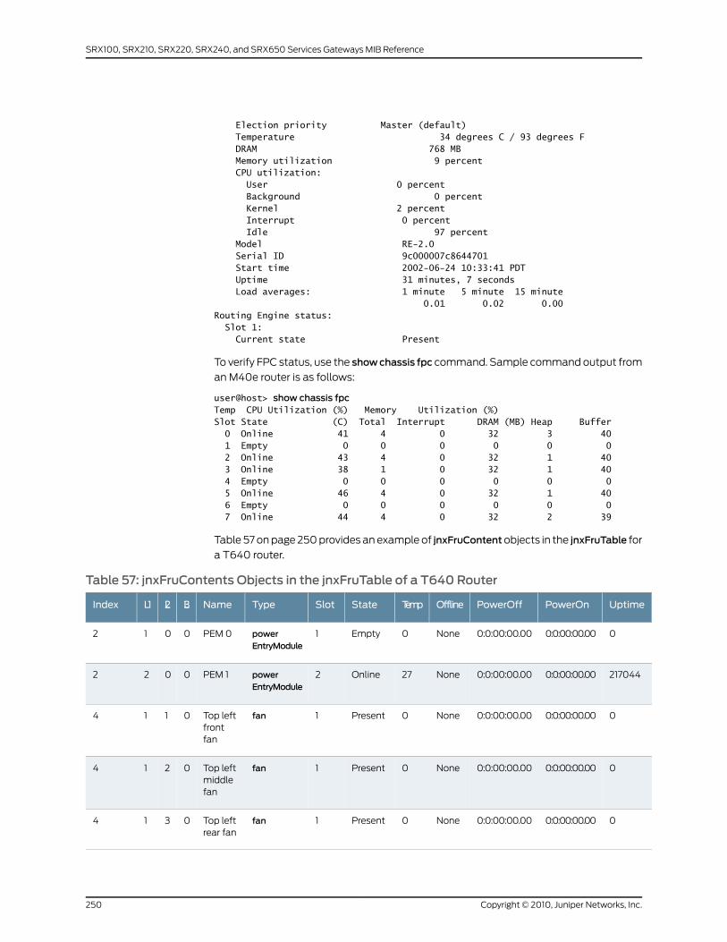
Election priority Master (default) Temperature 34 degrees C / 93 degrees F DRAM 768 MB Memory utilization 9 percent CPU utilization: User 0 percent Background 0 percent Kernel 2 percent Interrupt 0 percent Idle 97 percent Model RE-2.0 Serial ID 9c000007c8644701 Start time 2002-06-24 10:33:41 PDT Uptime 31 minutes, 7 seconds Load averages: 1 minute 5 minute 15 minute 0.01 0.02 0.00Routing Engine status: Slot 1: Current state Present
To verify FPC status, use the showchassis fpc command. Sample command output from
an M40e router is as follows:
user@host> show chassis fpcTemp CPU Utilization (%) Memory Utilization (%)Slot State (C) Total Interrupt DRAM (MB) Heap Buffer 0 Online 41 4 0 32 3 40 1 Empty 0 0 0 0 0 0 2 Online 43 4 0 32 1 40 3 Online 38 1 0 32 1 40 4 Empty 0 0 0 0 0 0 5 Online 46 4 0 32 1 40 6 Empty 0 0 0 0 0 0 7 Online 44 4 0 32 2 39
Table 57 on page 250 provides an example of jnxFruContentobjects in the jnxFruTable for
a T640 router.
Table 57: jnxFruContents Objects in the jnxFruTable of a T640 Router
UptimePowerOnPowerOffOfflineTempStateSlotTypeNameL3L2L1Index
00:0:00:00.000:0:00:00.00None0Empty1powerEntryModule
PEM 00012
2170440:0:00:00.000:0:00:00.00None27Online2powerEntryModule
PEM 10022
00:0:00:00.000:0:00:00.00None0Present1fanTop leftfrontfan
0114
00:0:00:00.000:0:00:00.00None0Present1fanTop leftmiddlefan
0214
00:0:00:00.000:0:00:00.00None0Present1fanTop leftrear fan
0314
Copyright © 2010, Juniper Networks, Inc.250
SRX100, SRX210, SRX220, SRX240, and SRX650 Services Gateways MIB Reference
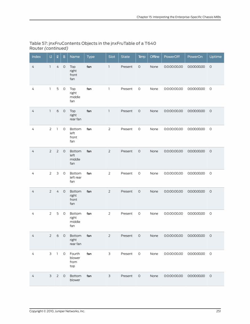
Table 57: jnxFruContents Objects in the jnxFruTable of a T640Router (continued)
UptimePowerOnPowerOffOfflineTempStateSlotTypeNameL3L2L1Index
00:0:00:00.000:0:00:00.00None0Present1fanToprightfrontfan
0414
00:0:00:00.000:0:00:00.00None0Present1fanToprightmiddlefan
0514
00:0:00:00.000:0:00:00.00None0Present1fanToprightrear fan
0614
00:0:00:00.000:0:00:00.00None0Present2fanBottomleftfrontfan
0124
00:0:00:00.000:0:00:00.00None0Present2fanBottomleftmiddlefan
0224
00:0:00:00.000:0:00:00.00None0Present2fanBottomleft rearfan
0324
00:0:00:00.000:0:00:00.00None0Present2fanBottomrightfrontfan
0424
00:0:00:00.000:0:00:00.00None0Present2fanBottomrightmiddlefan
0524
00:0:00:00.000:0:00:00.00None0Present2fanBottomrightrear fan
0624
00:0:00:00.000:0:00:00.00None0Present3fanFourthblowerfromtop
0134
00:0:00:00.000:0:00:00.00None0Present3fanBottomblower
0234
251Copyright © 2010, Juniper Networks, Inc.
Chapter 15: Interpreting the Enterprise-Specific Chassis MIBs
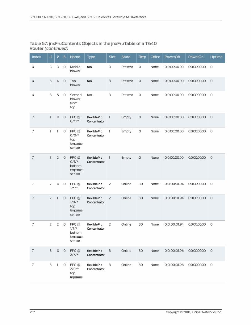
Table 57: jnxFruContents Objects in the jnxFruTable of a T640Router (continued)
UptimePowerOnPowerOffOfflineTempStateSlotTypeNameL3L2L1Index
00:0:00:00.000:0:00:00.00None0Present3fanMiddleblower
0334
00:0:00:00.000:0:00:00.00None0Present3fanTopblower
0434
00:0:00:00.000:0:00:00.00None0Present3fanSecondblowerfromtop
0534
00:0:00:00.000:0:00:00.00None0Empty1flexiblePicConcentrator
FPC @0/*/*
0017
00:0:00:00.000:0:00:00.00None0Empty1flexiblePicConcentrator
FPC @0/0/*toptemperaturesensor
0117
00:0:00:00.000:0:00:00.00None0Empty1flexiblePicConcentrator
FPC @0/1/*bottomtemperaturesensor
0217
00:0:00:00.000:0:00:01.94None30Online2flexiblePicConcentrator
FPC @1/*/*
0027
00:0:00:00.000:0:00:01.94None30Online2flexiblePicConcentrator
FPC @1/0/*toptemperaturesensor
0127
00:0:00:00.000:0:00:01.94None30Online2flexiblePicConcentrator
FPC @1/1/*bottomtemperaturesensor
0227
00:0:00:00.000:0:00:01.96None30Online3flexiblePicConcentrator
FPC @2/*/*
0037
00:0:00:00.000:0:00:01.96None30Online3flexiblePicConcentrator
FPC @2/0/*toptemperaturesensor
0137
Copyright © 2010, Juniper Networks, Inc.252
SRX100, SRX210, SRX220, SRX240, and SRX650 Services Gateways MIB Reference
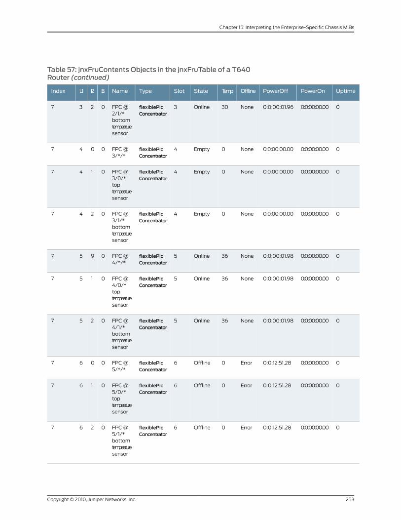
Table 57: jnxFruContents Objects in the jnxFruTable of a T640Router (continued)
UptimePowerOnPowerOffOfflineTempStateSlotTypeNameL3L2L1Index
00:0:00:00.000:0:00:01.96None30Online3flexiblePicConcentrator
FPC @2/1/*bottomtemperaturesensor
0237
00:0:00:00.000:0:00:00.00None0Empty4flexiblePicConcentrator
FPC @3/*/*
0047
00:0:00:00.000:0:00:00.00None0Empty4flexiblePicConcentrator
FPC @3/0/*toptemperaturesensor
0147
00:0:00:00.000:0:00:00.00None0Empty4flexiblePicConcentrator
FPC @3/1/*bottomtemperaturesensor
0247
00:0:00:00.000:0:00:01.98None36Online5flexiblePicConcentrator
FPC @4/*/*
0957
00:0:00:00.000:0:00:01.98None36Online5flexiblePicConcentrator
FPC @4/0/*toptemperaturesensor
0157
00:0:00:00.000:0:00:01.98None36Online5flexiblePicConcentrator
FPC @4/1/*bottomtemperaturesensor
0257
00:0:00:00.000:0:12:51.28Error0Offline6flexiblePicConcentrator
FPC @5/*/*
0067
00:0:00:00.000:0:12:51.28Error0Offline6flexiblePicConcentrator
FPC @5/0/*toptemperaturesensor
0167
00:0:00:00.000:0:12:51.28Error0Offline6flexiblePicConcentrator
FPC @5/1/*bottomtemperaturesensor
0267
253Copyright © 2010, Juniper Networks, Inc.
Chapter 15: Interpreting the Enterprise-Specific Chassis MIBs
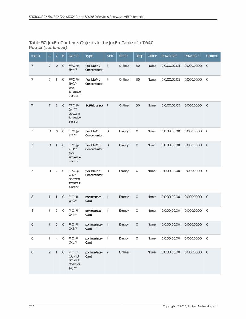
Table 57: jnxFruContents Objects in the jnxFruTable of a T640Router (continued)
UptimePowerOnPowerOffOfflineTempStateSlotTypeNameL3L2L1Index
00:0:00:00.000:0:00:02.05None30Online7flexiblePicConcentrator
FPC @6/*/*
0077
00:0:00:00.000:0:00:02.05None30Online7flexiblePicConcentrator
FPC @6/0/*toptemperaturesensor
0177
00:0:00:00.000:0:00:02.05None30Online7flexiblePicConcentratorFPC @6/1/*bottomtemperaturesensor
0277
00:0:00:00.000:0:00:00.00None0Empty8flexiblePicConcentrator
FPC @7/*/*
0087
00:0:00:00.000:0:00:00.00None0Empty8flexiblePicConcentrator
FPC @7/0/*toptemperaturesensor
0187
00:0:00:00.000:0:00:00.00None0Empty8flexiblePicConcentrator
FPC @7/1/*bottomtemperaturesensor
0287
00:0:00:00.000:0:00:00.00None0Empty1portInterface-Card
PIC: @0/0/*
0118
00:0:00:00.000:0:00:00.00None0Empty1portInterface-Card
PIC: @0/1/*
0218
00:0:00:00.000:0:00:00.00None0Empty1portInterface-Card
PIC: @0/2/*
0318
00:0:00:00.000:0:00:00.00None0Empty1portInterface-Card
PIC: @0/3/*
0418
00:0:00:00.000:0:00:00.00NoneOnline2portInterface-Card
PIC: 1xOC-48SONET,SMIR @1/0/*
0128
Copyright © 2010, Juniper Networks, Inc.254
SRX100, SRX210, SRX220, SRX240, and SRX650 Services Gateways MIB Reference
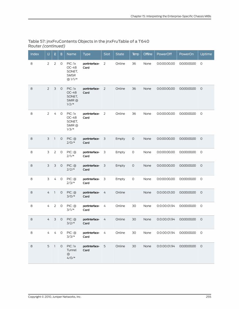
Table 57: jnxFruContents Objects in the jnxFruTable of a T640Router (continued)
UptimePowerOnPowerOffOfflineTempStateSlotTypeNameL3L2L1Index
00:0:00:00.000:0:00:00.00None36Online2portInterface-Card
PIC: 1xOC-48SONET,SMSR@ 1/1/*
0228
00:0:00:00.000:0:00:00.00None36Online2portInterface-Card
PIC: 1xOC-48SONET,SMIR @1/2/*
0328
00:0:00:00.000:0:00:00.00None36Online2portInterface-Card
PIC: 1xOC-48SONET,SMIR @1/3/*
0428
00:0:00:00.000:0:00:00.00None0Empty3portInterface-Card
PIC: @2/0/*
0138
00:0:00:00.000:0:00:00.00None0Empty3portInterface-Card
PIC: @2/1/*
0238
00:0:00:00.000:0:00:00.00None0Empty3portInterface-Card
PIC: @2/2/*
0338
00:0:00:00.000:0:00:00.00None0Empty3portInterface-Card
PIC: @2/3/*
0438
00:0:00:00.000:0:00:01.00NoneOnline4portInterface-Card
PIC: @3/0/*
0148
00:0:00:00.000:0:00:01.94None30Online4portInterface-Card
PIC: @3/1/*
0248
00:0:00:00.000:0:00:01.94None30Online4portInterface-Card
PIC: @3/2/*
0348
00:0:00:00.000:0:00:01.94None30Online4portInterface-Card
PIC: @3/3/*
0448
00:0:00:00.000:0:00:01.94None30Online5portInterface-Card
PIC: 1xTunnel@4/0/*
0158
255Copyright © 2010, Juniper Networks, Inc.
Chapter 15: Interpreting the Enterprise-Specific Chassis MIBs
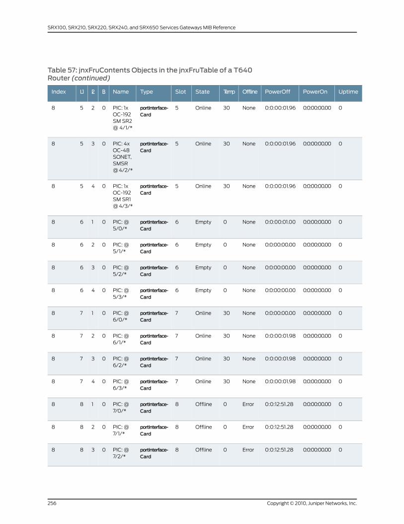
Table 57: jnxFruContents Objects in the jnxFruTable of a T640Router (continued)
UptimePowerOnPowerOffOfflineTempStateSlotTypeNameL3L2L1Index
00:0:00:00.000:0:00:01.96None30Online5portInterface-Card
PIC: 1xOC-192SM SR2@ 4/1/*
0258
00:0:00:00.000:0:00:01.96None30Online5portInterface-Card
PIC: 4xOC-48SONET,SMSR@ 4/2/*
0358
00:0:00:00.000:0:00:01.96None30Online5portInterface-Card
PIC: 1xOC-192SM SR1@ 4/3/*
0458
00:0:00:00.000:0:00:01.00None0Empty6portInterface-Card
PIC: @5/0/*
0168
00:0:00:00.000:0:00:00.00None0Empty6portInterface-Card
PIC: @5/1/*
0268
00:0:00:00.000:0:00:00.00None0Empty6portInterface-Card
PIC: @5/2/*
0368
00:0:00:00.000:0:00:00.00None0Empty6portInterface-Card
PIC: @5/3/*
0468
00:0:00:00.000:0:00:00.00None30Online7portInterface-Card
PIC: @6/0/*
0178
00:0:00:00.000:0:00:01.98None30Online7portInterface-Card
PIC: @6/1/*
0278
00:0:00:00.000:0:00:01.98None30Online7portInterface-Card
PIC: @6/2/*
0378
00:0:00:00.000:0:00:01.98None30Online7portInterface-Card
PIC: @6/3/*
0478
00:0:00:00.000:0:12:51.28Error0Offline8portInterface-Card
PIC: @7/0/*
0188
00:0:00:00.000:0:12:51.28Error0Offline8portInterface-Card
PIC: @7/1/*
0288
00:0:00:00.000:0:12:51.28Error0Offline8portInterface-Card
PIC: @7/2/*
0388
Copyright © 2010, Juniper Networks, Inc.256
SRX100, SRX210, SRX220, SRX240, and SRX650 Services Gateways MIB Reference
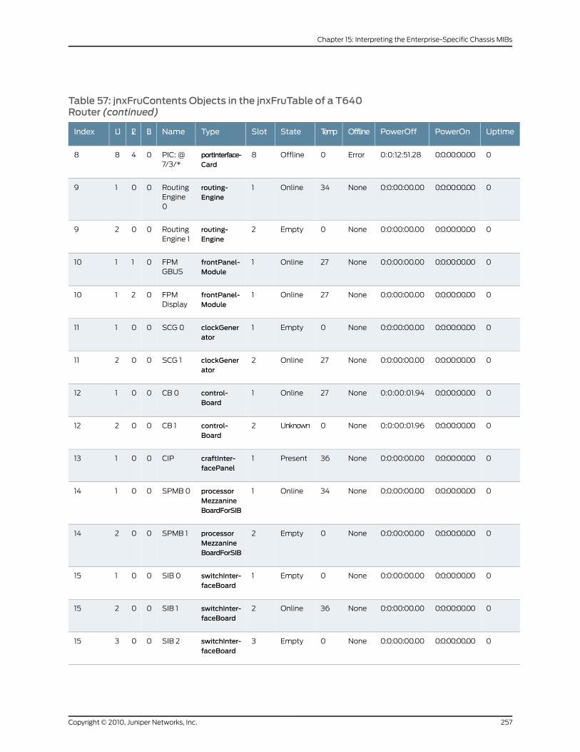
Table 57: jnxFruContents Objects in the jnxFruTable of a T640Router (continued)
UptimePowerOnPowerOffOfflineTempStateSlotTypeNameL3L2L1Index
00:0:00:00.000:0:12:51.28Error0Offline8portInterface-Card
PIC: @7/3/*
0488
00:0:00:00.000:0:00:00.00None34Online1routing-Engine
RoutingEngine0
0019
00:0:00:00.000:0:00:00.00None0Empty2routing-Engine
RoutingEngine 1
0029
00:0:00:00.000:0:00:00.00None27Online1frontPanel-Module
FPMGBUS
01110
00:0:00:00.000:0:00:00.00None27Online1frontPanel-Module
FPMDisplay
02110
00:0:00:00.000:0:00:00.00None0Empty1clockGenerator
SCG 000111
00:0:00:00.000:0:00:00.00None27Online2clockGenerator
SCG 100211
00:0:00:00.000:0:00:01.94None27Online1control-Board
CB 000112
00:0:00:00.000:0:00:01.96None0Unknown2control-Board
CB 100212
00:0:00:00.000:0:00:00.00None36Present1craftInter-facePanel
CIP00113
00:0:00:00.000:0:00:00.00None34Online1processorMezzanineBoardForSIB
SPMB 000114
00:0:00:00.000:0:00:00.00None0Empty2processorMezzanineBoardForSIB
SPMB 100214
00:0:00:00.000:0:00:00.00None0Empty1switchInter-faceBoard
SIB 000115
00:0:00:00.000:0:00:00.00None36Online2switchInter-faceBoard
SIB 100215
00:0:00:00.000:0:00:00.00None0Empty3switchInter-faceBoard
SIB 200315
257Copyright © 2010, Juniper Networks, Inc.
Chapter 15: Interpreting the Enterprise-Specific Chassis MIBs
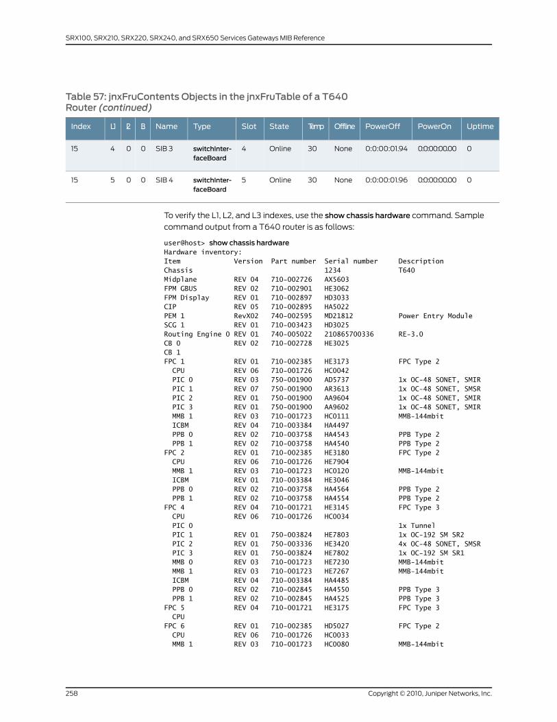
Table 57: jnxFruContents Objects in the jnxFruTable of a T640Router (continued)
UptimePowerOnPowerOffOfflineTempStateSlotTypeNameL3L2L1Index
00:0:00:00.000:0:00:01.94None30Online4switchInter-faceBoard
SIB 300415
00:0:00:00.000:0:00:01.96None30Online5switchInter-faceBoard
SIB 400515
To verify the L1, L2, and L3 indexes, use the show chassis hardware command. Sample
command output from a T640 router is as follows:
user@host> show chassis hardwareHardware inventory:Item Version Part number Serial number DescriptionChassis 1234 T640Midplane REV 04 710-002726 AX5603FPM GBUS REV 02 710-002901 HE3062FPM Display REV 01 710-002897 HD3033CIP REV 05 710-002895 HA5022PEM 1 RevX02 740-002595 MD21812 Power Entry ModuleSCG 1 REV 01 710-003423 HD3025Routing Engine 0 REV 01 740-005022 210865700336 RE-3.0CB 0 REV 02 710-002728 HE3025CB 1FPC 1 REV 01 710-002385 HE3173 FPC Type 2 CPU REV 06 710-001726 HC0042 PIC 0 REV 03 750-001900 AD5737 1x OC-48 SONET, SMIR PIC 1 REV 07 750-001900 AR3613 1x OC-48 SONET, SMSR PIC 2 REV 01 750-001900 AA9604 1x OC-48 SONET, SMIR PIC 3 REV 01 750-001900 AA9602 1x OC-48 SONET, SMIR MMB 1 REV 03 710-001723 HC0111 MMB-144mbit ICBM REV 04 710-003384 HA4497 PPB 0 REV 02 710-003758 HA4543 PPB Type 2 PPB 1 REV 02 710-003758 HA4540 PPB Type 2FPC 2 REV 01 710-002385 HE3180 FPC Type 2 CPU REV 06 710-001726 HE7904 MMB 1 REV 03 710-001723 HC0120 MMB-144mbit ICBM REV 01 710-003384 HE3046 PPB 0 REV 02 710-003758 HA4564 PPB Type 2 PPB 1 REV 02 710-003758 HA4554 PPB Type 2FPC 4 REV 04 710-001721 HE3145 FPC Type 3 CPU REV 06 710-001726 HC0034 PIC 0 1x Tunnel PIC 1 REV 01 750-003824 HE7803 1x OC-192 SM SR2 PIC 2 REV 01 750-003336 HE3420 4x OC-48 SONET, SMSR PIC 3 REV 01 750-003824 HE7802 1x OC-192 SM SR1 MMB 0 REV 03 710-001723 HE7230 MMB-144mbit MMB 1 REV 03 710-001723 HE7267 MMB-144mbit ICBM REV 04 710-003384 HA4485 PPB 0 REV 02 710-002845 HA4550 PPB Type 3 PPB 1 REV 02 710-002845 HA4525 PPB Type 3FPC 5 REV 04 710-001721 HE3175 FPC Type 3 CPUFPC 6 REV 01 710-002385 HD5027 FPC Type 2 CPU REV 06 710-001726 HC0033 MMB 1 REV 03 710-001723 HC0080 MMB-144mbit
Copyright © 2010, Juniper Networks, Inc.258
SRX100, SRX210, SRX220, SRX240, and SRX650 Services Gateways MIB Reference
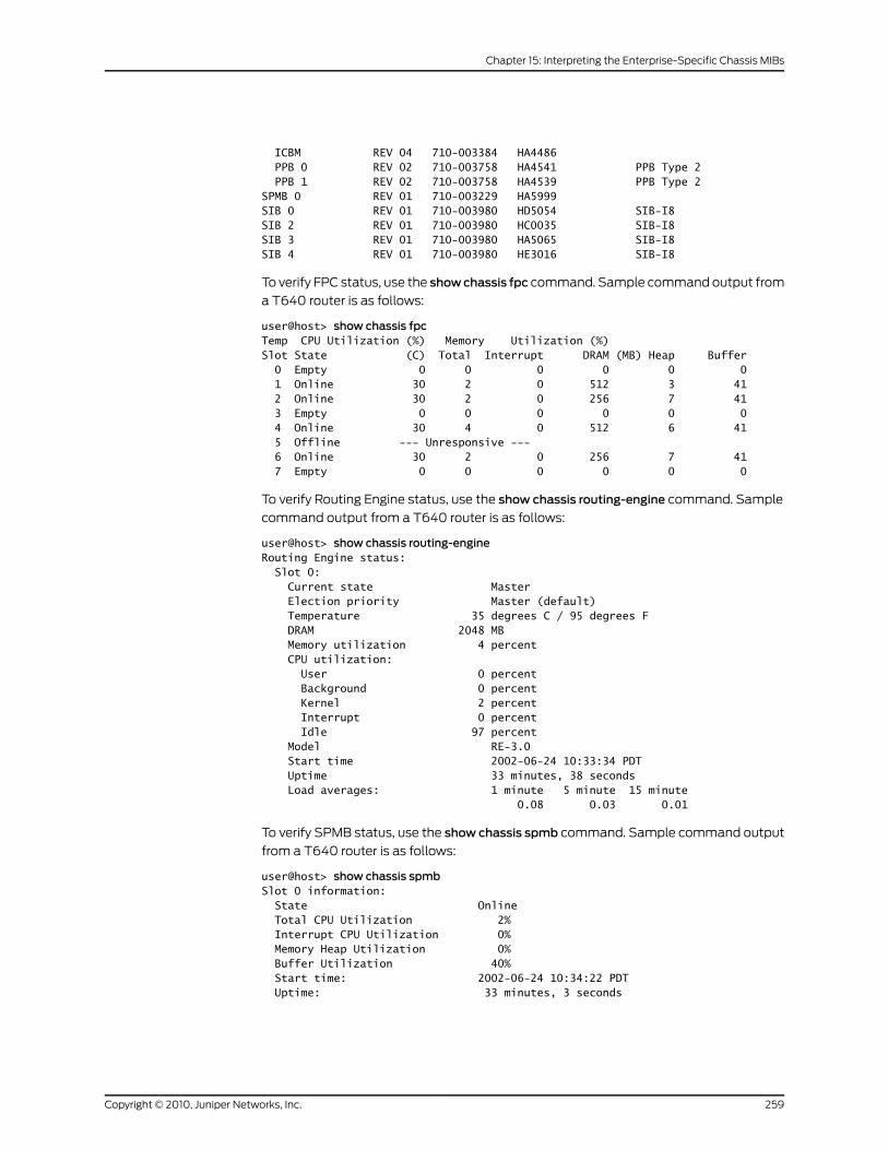
ICBM REV 04 710-003384 HA4486 PPB 0 REV 02 710-003758 HA4541 PPB Type 2 PPB 1 REV 02 710-003758 HA4539 PPB Type 2SPMB 0 REV 01 710-003229 HA5999SIB 0 REV 01 710-003980 HD5054 SIB-I8SIB 2 REV 01 710-003980 HC0035 SIB-I8SIB 3 REV 01 710-003980 HA5065 SIB-I8SIB 4 REV 01 710-003980 HE3016 SIB-I8
To verify FPC status, use the showchassis fpc command. Sample command output from
a T640 router is as follows:
user@host> show chassis fpcTemp CPU Utilization (%) Memory Utilization (%)Slot State (C) Total Interrupt DRAM (MB) Heap Buffer 0 Empty 0 0 0 0 0 0 1 Online 30 2 0 512 3 41 2 Online 30 2 0 256 7 41 3 Empty 0 0 0 0 0 0 4 Online 30 4 0 512 6 41 5 Offline --- Unresponsive --- 6 Online 30 2 0 256 7 41 7 Empty 0 0 0 0 0 0
To verify Routing Engine status, use the show chassis routing-engine command. Sample
command output from a T640 router is as follows:
user@host> show chassis routing-engineRouting Engine status: Slot 0: Current state Master Election priority Master (default) Temperature 35 degrees C / 95 degrees F DRAM 2048 MB Memory utilization 4 percent CPU utilization: User 0 percent Background 0 percent Kernel 2 percent Interrupt 0 percent Idle 97 percent Model RE-3.0 Start time 2002-06-24 10:33:34 PDT Uptime 33 minutes, 38 seconds Load averages: 1 minute 5 minute 15 minute 0.08 0.03 0.01
To verify SPMB status, use the show chassis spmb command. Sample command output
from a T640 router is as follows:
user@host> show chassis spmbSlot 0 information: State Online Total CPU Utilization 2% Interrupt CPU Utilization 0% Memory Heap Utilization 0% Buffer Utilization 40% Start time: 2002-06-24 10:34:22 PDT Uptime: 33 minutes, 3 seconds
259Copyright © 2010, Juniper Networks, Inc.
Chapter 15: Interpreting the Enterprise-Specific Chassis MIBs
jnxBoxKernelMemoryUsedPercent
The object identifier for jnxBoxKernelMemoryUsedPercent is jnxBoxAnatomy 16. This
object represents the amount of the kernel memory used, expressed as a percentage of
the total available memory. The object shows0 if the kernel memory usage is unavailable
or inapplicable. When the kernel memory usage exceeds 80 percent, a system log
message is logged and an RMON rising threshold trap is generated if RMON health
monitoring is enabled for the device.
jnxBoxSystemDomainType
The object identifier for jnxBoxSystemDomainType is jnxBoxAnatomy 17. This object
indicates the domain type of the device, that is whether it is a root system domain (RSD;
represented by integer 2) or a protected system domain (PSD; represented by integer
3). This object returns an integer value of 1, denoting not applicable, if the system domain
type feature is not supported on the device.
RelatedDocumentation
Chassis MIBs•
• Textual Convention for Chassis MIB on page 174
• Chassis Traps on page 260
Chassis Traps
The chassis-related traps are defined under the jnxTrapsand jnxChassisOKtrapsbranches.
For the system logging severity levels for these traps, see .Juniper Networks
Enterprise-Specific SNMP Traps .
These traps are defined as follows:
• Power failure (jnxPowerSupplyFailure)—Sent when the power supply, router circuit
breaker, or power circuit fails, or when there is a power outage. When only one of the
power supplies has failed, the service impact is minimal. One power supply can provide
the necessary power for a fully loaded router. To determine the source of the failure,
you must physically inspect the router. This trap is repeated every hour until the power
supply is restored.
• Fan failure (jnxFanFailure)—Sent when the fan fuse blows or when the fan wiring shorts
out. When only one fan has failed, there is no service impact. The remaining fans
increase speed to compensate. However, you must resolve the problem before another
fan fails. This trap is repeated every hour until the fan failure is fixed. To determine the
source of the failure, you must physically inspect the router, taking care to check the
fuses. See the hardware installation guide for your router model for more information.
• Overtemperature (jnxOverTemperature)—Sent when several fans fail or the room
temperature increases significantly. The service impact of this trap depends on the
temperature of the router. In general, the router increases the speed of the fans when
any component exceeds a temperature of 55=° C. The fans remain at the higher speed
until the temperature decreases below the threshold. In this case, there is no service
impact. However, if the temperature exceeds 75° C, the router transmits a warning
Copyright © 2010, Juniper Networks, Inc.260
SRX100, SRX210, SRX220, SRX240, and SRX650 Services Gateways MIB Reference
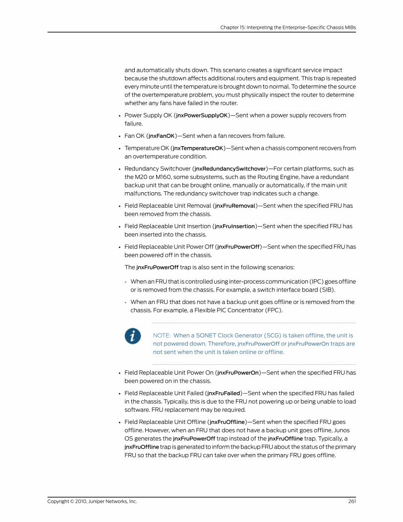
and automatically shuts down. This scenario creates a significant service impact
because the shutdown affects additional routers and equipment. This trap is repeated
every minute until the temperature is brought down to normal. To determine the source
of the overtemperature problem, you must physically inspect the router to determine
whether any fans have failed in the router.
• Power Supply OK (jnxPowerSupplyOK)—Sent when a power supply recovers from
failure.
• Fan OK (jnxFanOK)—Sent when a fan recovers from failure.
• Temperature OK (jnxTemperatureOK)—Sent when a chassis component recovers from
an overtemperature condition.
• Redundancy Switchover (jnxRedundancySwitchover)—For certain platforms, such as
the M20 or M160, some subsystems, such as the Routing Engine, have a redundant
backup unit that can be brought online, manually or automatically, if the main unit
malfunctions. The redundancy switchover trap indicates such a change.
• Field Replaceable Unit Removal (jnxFruRemoval)—Sent when the specified FRU has
been removed from the chassis.
• Field Replaceable Unit Insertion (jnxFruInsertion)—Sent when the specified FRU has
been inserted into the chassis.
• Field Replaceable Unit Power Off (jnxFruPowerOff)—Sent when the specified FRU has
been powered off in the chassis.
The jnxFruPowerOff trap is also sent in the following scenarios:
• When an FRU that is controlled using inter-process communication (IPC) goes offline
or is removed from the chassis. For example, a switch interface board (SIB).
• When an FRU that does not have a backup unit goes offline or is removed from the
chassis. For example, a Flexible PIC Concentrator (FPC).
NOTE: When a SONET Clock Generator (SCG) is taken offline, the unit isnot powered down. Therefore, jnxFruPowerOff or jnxFruPowerOn traps are
not sent when the unit is taken online or offline.
• Field Replaceable Unit Power On (jnxFruPowerOn)—Sent when the specified FRU has
been powered on in the chassis.
• Field Replaceable Unit Failed (jnxFruFailed)—Sent when the specified FRU has failed
in the chassis. Typically, this is due to the FRU not powering up or being unable to load
software. FRU replacement may be required.
• Field Replaceable Unit Offline (jnxFruOffline)—Sent when the specified FRU goes
offline. However, when an FRU that does not have a backup unit goes offline, Junos
OS generates the jnxFruPowerOff trap instead of the jnxFruOffline trap. Typically, a
jnxFruOffline trap is generated to inform the backup FRU about the status of the primary
FRU so that the backup FRU can take over when the primary FRU goes offline.
261Copyright © 2010, Juniper Networks, Inc.
Chapter 15: Interpreting the Enterprise-Specific Chassis MIBs
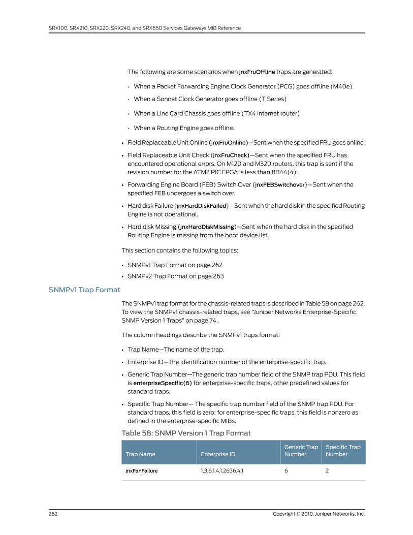
The following are some scenarios when jnxFruOffline traps are generated:
• When a Packet Forwarding Engine Clock Generator (PCG) goes offline (M40e)
• When a Sonnet Clock Generator goes offline (T Series)
• When a Line Card Chassis goes offline (TX4 internet router)
• When a Routing Engine goes offline.
• Field Replaceable Unit Online (jnxFruOnline)—Sent when the specified FRU goes online.
• Field Replaceable Unit Check (jnxFruCheck)—Sent when the specified FRU has
encountered operational errors. On M120 and M320 routers, this trap is sent if the
revision number for the ATM2 PIC FPGA is less than 8B44(4).
• Forwarding Engine Board (FEB) Switch Over (jnxFEBSwitchover)—Sent when the
specified FEB undergoes a switch over.
• Hard disk Failure (jnxHardDiskFailed)—Sent when the hard disk in the specified Routing
Engine is not operational.
• Hard disk Missing (jnxHardDiskMissing)—Sent when the hard disk in the specified
Routing Engine is missing from the boot device list.
This section contains the following topics:
• SNMPv1 Trap Format on page 262
• SNMPv2 Trap Format on page 263
SNMPv1 Trap Format
The SNMPv1 trap format for the chassis-related traps is described in Table 58 on page 262.
To view the SNMPv1 chassis-related traps, see “Juniper Networks Enterprise-Specific
SNMP Version 1 Traps” on page 74 .
The column headings describe the SNMPv1 traps format:
• Trap Name—The name of the trap.
• Enterprise ID—The identification number of the enterprise-specific trap.
• Generic Trap Number—The generic trap number field of the SNMP trap PDU. This field
is enterpriseSpecific(6) for enterprise-specific traps, other predefined values for
standard traps.
• Specific Trap Number— The specific trap number field of the SNMP trap PDU. For
standard traps, this field is zero; for enterprise-specific traps, this field is nonzero as
defined in the enterprise-specific MIBs.
Table 58: SNMPVersion 1 Trap Format
Specific TrapNumber
Generic TrapNumberEnterprise IDTrap Name
261.3.6.1.4.1.2636.4.1jnxFanFailure
Copyright © 2010, Juniper Networks, Inc.262
SRX100, SRX210, SRX220, SRX240, and SRX650 Services Gateways MIB Reference
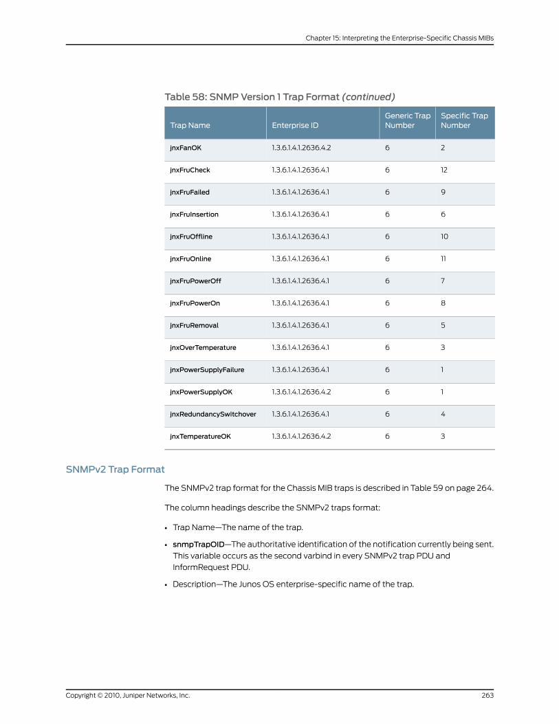
Table 58: SNMPVersion 1 Trap Format (continued)
Specific TrapNumber
Generic TrapNumberEnterprise IDTrap Name
261.3.6.1.4.1.2636.4.2jnxFanOK
1261.3.6.1.4.1.2636.4.1jnxFruCheck
961.3.6.1.4.1.2636.4.1jnxFruFailed
661.3.6.1.4.1.2636.4.1jnxFruInsertion
1061.3.6.1.4.1.2636.4.1jnxFruOffline
1161.3.6.1.4.1.2636.4.1jnxFruOnline
761.3.6.1.4.1.2636.4.1jnxFruPowerOff
861.3.6.1.4.1.2636.4.1jnxFruPowerOn
561.3.6.1.4.1.2636.4.1jnxFruRemoval
361.3.6.1.4.1.2636.4.1jnxOverTemperature
161.3.6.1.4.1.2636.4.1jnxPowerSupplyFailure
161.3.6.1.4.1.2636.4.2jnxPowerSupplyOK
461.3.6.1.4.1.2636.4.1jnxRedundancySwitchover
361.3.6.1.4.1.2636.4.2jnxTemperatureOK
SNMPv2 Trap Format
The SNMPv2 trap format for the Chassis MIB traps is described in Table 59 on page 264.
The column headings describe the SNMPv2 traps format:
• Trap Name—The name of the trap.
• snmpTrapOID—The authoritative identification of the notification currently being sent.
This variable occurs as the second varbind in every SNMPv2 trap PDU and
InformRequest PDU.
• Description—The Junos OS enterprise-specific name of the trap.
263Copyright © 2010, Juniper Networks, Inc.
Chapter 15: Interpreting the Enterprise-Specific Chassis MIBs
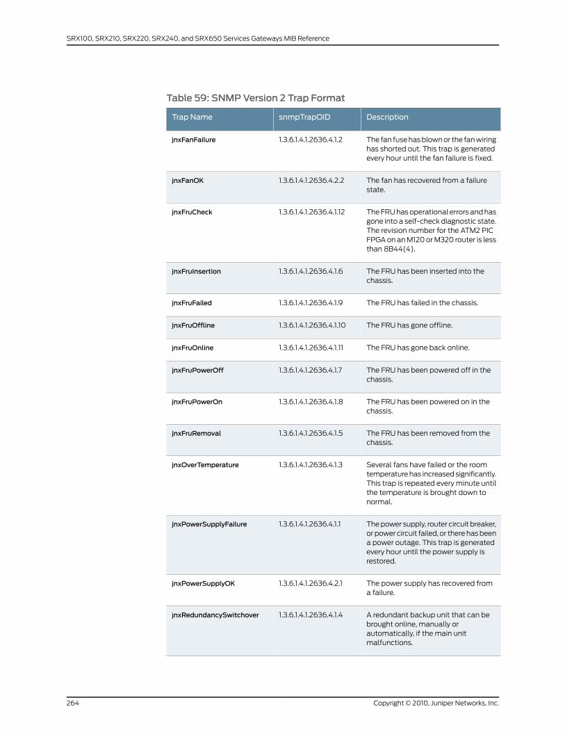
Table 59: SNMPVersion 2 Trap Format
DescriptionsnmpTrapOIDTrap Name
The fan fuse has blown or the fan wiringhas shorted out. This trap is generatedevery hour until the fan failure is fixed.
1.3.6.1.4.1.2636.4.1.2jnxFanFailure
The fan has recovered from a failurestate.
1.3.6.1.4.1.2636.4.2.2jnxFanOK
The FRU has operational errors and hasgone into a self-check diagnostic state.The revision number for the ATM2 PICFPGA on an M120 or M320 router is lessthan 8B44(4).
1.3.6.1.4.1.2636.4.1.12jnxFruCheck
The FRU has been inserted into thechassis.
1.3.6.1.4.1.2636.4.1.6jnxFruInsertion
The FRU has failed in the chassis.1.3.6.1.4.1.2636.4.1.9jnxFruFailed
The FRU has gone offline.1.3.6.1.4.1.2636.4.1.10jnxFruOffline
The FRU has gone back online.1.3.6.1.4.1.2636.4.1.11jnxFruOnline
The FRU has been powered off in thechassis.
1.3.6.1.4.1.2636.4.1.7jnxFruPowerOff
The FRU has been powered on in thechassis.
1.3.6.1.4.1.2636.4.1.8jnxFruPowerOn
The FRU has been removed from thechassis.
1.3.6.1.4.1.2636.4.1.5jnxFruRemoval
Several fans have failed or the roomtemperature has increased significantly.This trap is repeated every minute untilthe temperature is brought down tonormal.
1.3.6.1.4.1.2636.4.1.3jnxOverTemperature
The power supply, router circuit breaker,or power circuit failed, or there has beena power outage. This trap is generatedevery hour until the power supply isrestored.
1.3.6.1.4.1.2636.4.1.1jnxPowerSupplyFailure
The power supply has recovered froma failure.
1.3.6.1.4.1.2636.4.2.1jnxPowerSupplyOK
A redundant backup unit that can bebrought online, manually orautomatically, if the main unitmalfunctions.
1.3.6.1.4.1.2636.4.1.4jnxRedundancySwitchover
Copyright © 2010, Juniper Networks, Inc.264
SRX100, SRX210, SRX220, SRX240, and SRX650 Services Gateways MIB Reference
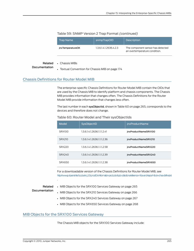
Table 59: SNMPVersion 2 Trap Format (continued)
DescriptionsnmpTrapOIDTrap Name
The component sensor has detectedan overtemperature condition.
1.3.6.1.4.1.2636.4.2.3jnxTemperatureOK
RelatedDocumentation
Chassis MIBs•
• Textual Convention for Chassis MIB on page 174
Chassis Definitions for Router Model MIB
The enterprise-specific Chassis Definitions for Router Model MIB contain the OIDs that
are used by the Chassis MIB to identify platform and chassis components. The Chassis
MIB provides information that changes often. The Chassis Definitions for the Router
Model MIB provide information that changes less often.
The last number in each sysObjectId, shown in Table 60 on page 265, corresponds to the
devices and therefore does not change.
Table 60: Router Model and Their sysObjectIds
jnxProductNameSysObjectIDModel
jnxProductNameSRX1001.3.6.1.4.1.2636.1.1.1.2.41SRX100
jnxProductNameSRX2101.3.6.1.4.1.2636.1.1.1.2.36SRX210
jnxProductNameSRX2201.3.6.1.4.1.2636.1.1.1.2.58SRX220
jnxProductNameSRX2401.3.6.1.4.1.2636.1.1.1.2.39SRX240
jnxProductNameSRX6501.3.6.1.4.1.2636.1.1.1.2.38SRX650
For a downloadable version of the Chassis Definitions for Router Model MIB, see
http://www.juniper.net/techpubs/en_US/junos10.4/information-products/topic-collections/reference-mibs-and-traps/mib-jnx-chas-defines.txt
.
RelatedDocumentation
MIB Objects for the SRX100 Services Gateway on page 265•
• MIB Objects for the SRX210 Services Gateway on page 266
• MIB Objects for the SRX240 Services Gateway on page 267
• MIB Objects for the SRX650 Services Gateway on page 268
MIBObjects for the SRX100 Services Gateway
The Chassis MIB objects for the SRX100 Services Gateway include:
265Copyright © 2010, Juniper Networks, Inc.
Chapter 15: Interpreting the Enterprise-Specific Chassis MIBs
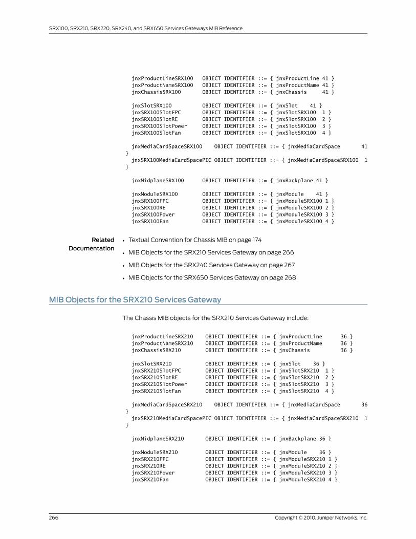
jnxProductLineSRX100 OBJECT IDENTIFIER ::= { jnxProductLine 41 } jnxProductNameSRX100 OBJECT IDENTIFIER ::= { jnxProductName 41 } jnxChassisSRX100 OBJECT IDENTIFIER ::= { jnxChassis 41 }
jnxSlotSRX100 OBJECT IDENTIFIER ::= { jnxSlot 41 } jnxSRX100SlotFPC OBJECT IDENTIFIER ::= { jnxSlotSRX100 1 } jnxSRX100SlotRE OBJECT IDENTIFIER ::= { jnxSlotSRX100 2 } jnxSRX100SlotPower OBJECT IDENTIFIER ::= { jnxSlotSRX100 3 } jnxSRX100SlotFan OBJECT IDENTIFIER ::= { jnxSlotSRX100 4 }
jnxMediaCardSpaceSRX100 OBJECT IDENTIFIER ::= { jnxMediaCardSpace 41 } jnxSRX100MediaCardSpacePIC OBJECT IDENTIFIER ::= { jnxMediaCardSpaceSRX100 1 }
jnxMidplaneSRX100 OBJECT IDENTIFIER ::= { jnxBackplane 41 }
jnxModuleSRX100 OBJECT IDENTIFIER ::= { jnxModule 41 } jnxSRX100FPC OBJECT IDENTIFIER ::= { jnxModuleSRX100 1 } jnxSRX100RE OBJECT IDENTIFIER ::= { jnxModuleSRX100 2 } jnxSRX100Power OBJECT IDENTIFIER ::= { jnxModuleSRX100 3 } jnxSRX100Fan OBJECT IDENTIFIER ::= { jnxModuleSRX100 4 }
RelatedDocumentation
Textual Convention for Chassis MIB on page 174•
• MIB Objects for the SRX210 Services Gateway on page 266
• MIB Objects for the SRX240 Services Gateway on page 267
• MIB Objects for the SRX650 Services Gateway on page 268
MIBObjects for the SRX210 Services Gateway
The Chassis MIB objects for the SRX210 Services Gateway include:
jnxProductLineSRX210 OBJECT IDENTIFIER ::= { jnxProductLine 36 } jnxProductNameSRX210 OBJECT IDENTIFIER ::= { jnxProductName 36 } jnxChassisSRX210 OBJECT IDENTIFIER ::= { jnxChassis 36 }
jnxSlotSRX210 OBJECT IDENTIFIER ::= { jnxSlot 36 } jnxSRX210SlotFPC OBJECT IDENTIFIER ::= { jnxSlotSRX210 1 } jnxSRX210SlotRE OBJECT IDENTIFIER ::= { jnxSlotSRX210 2 } jnxSRX210SlotPower OBJECT IDENTIFIER ::= { jnxSlotSRX210 3 } jnxSRX210SlotFan OBJECT IDENTIFIER ::= { jnxSlotSRX210 4 }
jnxMediaCardSpaceSRX210 OBJECT IDENTIFIER ::= { jnxMediaCardSpace 36 } jnxSRX210MediaCardSpacePIC OBJECT IDENTIFIER ::= { jnxMediaCardSpaceSRX210 1 }
jnxMidplaneSRX210 OBJECT IDENTIFIER ::= { jnxBackplane 36 }
jnxModuleSRX210 OBJECT IDENTIFIER ::= { jnxModule 36 } jnxSRX210FPC OBJECT IDENTIFIER ::= { jnxModuleSRX210 1 } jnxSRX210RE OBJECT IDENTIFIER ::= { jnxModuleSRX210 2 } jnxSRX210Power OBJECT IDENTIFIER ::= { jnxModuleSRX210 3 } jnxSRX210Fan OBJECT IDENTIFIER ::= { jnxModuleSRX210 4 }
Copyright © 2010, Juniper Networks, Inc.266
SRX100, SRX210, SRX220, SRX240, and SRX650 Services Gateways MIB Reference
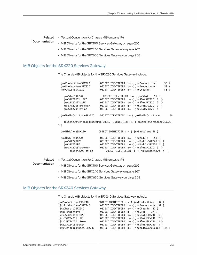
RelatedDocumentation
Textual Convention for Chassis MIB on page 174•
• MIB Objects for the SRX100 Services Gateway on page 265
• MIB Objects for the SRX240 Services Gateway on page 267
• MIB Objects for the SRX650 Services Gateway on page 268
MIBObjects for the SRX220 Services Gateway
The Chassis MIB objects for the SRX220 Services Gateway include:
jnxProductLineSRX220 OBJECT IDENTIFIER ::= { jnxProductLine 58 } jnxProductNameSRX220 OBJECT IDENTIFIER ::= { jnxProductName 58 } jnxChassisSRX220 OBJECT IDENTIFIER ::= { jnxChassis 58 }
jnxSlotSRX220 OBJECT IDENTIFIER ::= { jnxSlot 58 } jnxSRX220SlotFPC OBJECT IDENTIFIER ::= { jnxSlotSRX220 1 } jnxSRX220SlotRE OBJECT IDENTIFIER ::= { jnxSlotSRX220 2 } jnxSRX220SlotPower OBJECT IDENTIFIER ::= { jnxSlotSRX220 3 } jnxSRX220SlotFan OBJECT IDENTIFIER ::= { jnxSlotSRX220 4 }
jnxMediaCardSpaceSRX220 OBJECT IDENTIFIER ::= { jnxMediaCardSpace 58 } jnxSRX220MediaCardSpacePIC OBJECT IDENTIFIER ::= { jnxMediaCardSpaceSRX220 1 }
jnxMidplaneSRX220 OBJECT IDENTIFIER ::= { jnxBackplane 58 }
jnxModuleSRX220 OBJECT IDENTIFIER ::= { jnxModule 58 } jnxSRX220FPC OBJECT IDENTIFIER ::= { jnxModuleSRX220 1 } jnxSRX220RE OBJECT IDENTIFIER ::= { jnxModuleSRX220 2 } jnxSRX220SlotPower OBJECT IDENTIFIER ::= { jnxSlotSRX220 3 } jnxSRX220SlotFan OBJECT IDENTIFIER ::= { jnxSlotSRX220 4 }
RelatedDocumentation
Textual Convention for Chassis MIB on page 174•
• MIB Objects for the SRX100 Services Gateway on page 265
• MIB Objects for the SRX240 Services Gateway on page 267
• MIB Objects for the SRX650 Services Gateway on page 268
MIBObjects for the SRX240 Services Gateway
The Chassis MIB objects for the SRX240 Services Gateway include:
jnxProductLineJSRX240 OBJECT IDENTIFIER ::= { jnxProductLine 37 } jnxProductNameJSRX240 OBJECT IDENTIFIER ::= { jnxProductName 37 } jnxChassisJSRX240 OBJECT IDENTIFIER ::= { jnxChassis 37 } jnxSlotJSRX240 OBJECT IDENTIFIER ::= { jnxSlot 37 } jnxJSRX240SlotFPC OBJECT IDENTIFIER ::= { jnxSlotJSRX240 1 } jnxJSRX240SlotRE OBJECT IDENTIFIER ::= { jnxSlotJSRX240 2 } jnxJSRX240SlotPower OBJECT IDENTIFIER ::= { jnxSlotJSRX240 3 } jnxJSRX240SlotFan OBJECT IDENTIFIER ::= { jnxSlotJSRX240 4 } jnxMediaCardSpaceJSRX240 OBJECT IDENTIFIER ::= { jnxMediaCardSpace 37 }
267Copyright © 2010, Juniper Networks, Inc.
Chapter 15: Interpreting the Enterprise-Specific Chassis MIBs

jnxJSRX240MediaCardSpacePIC OBJECT IDENTIFIER ::= { jnxMediaCardSpaceJSRX240 1 } jnxMidplaneJSRX240 OBJECT IDENTIFIER ::= { jnxBackplane 37 } jnxModuleJSRX240 OBJECT IDENTIFIER ::= { jnxModule 37 } jnxJSRX240FPC OBJECT IDENTIFIER ::= { jnxModuleJSRX240 1 } jnxJSRX240RE OBJECT IDENTIFIER ::= { jnxModuleJSRX240 2 } jnxJSRX240Power OBJECT IDENTIFIER ::= { jnxModuleJSRX240 3 } jnxJSRX240Fan OBJECT IDENTIFIER ::= { jnxModuleJSRX240 4 }
RelatedDocumentation
Textual Convention for Chassis MIB on page 174•
• MIB Objects for the SRX100 Services Gateway on page 265
• MIB Objects for the SRX210 Services Gateway on page 266
• MIB Objects for the SRX650 Services Gateway on page 268
MIBObjects for the SRX650 Services Gateway
The Chassis MIB objects for the SRX650 Services Gateway include:
jnxProductLineJSRX650 OBJECT IDENTIFIER ::= { jnxProductLine 38 } jnxProductNameJSRX650 OBJECT IDENTIFIER ::= { jnxProductName 38 } jnxChassisJSRX650 OBJECT IDENTIFIER ::= { jnxChassis 38 } jnxSlotJSRX650 OBJECT IDENTIFIER ::= { jnxSlot 38 } jnxJSRX650SlotFPC OBJECT IDENTIFIER ::= { jnxSlotJSRX650 1 } jnxJSRX650SlotRE OBJECT IDENTIFIER ::= { jnxSlotJSRX650 2 } jnxJSRX650SlotPower OBJECT IDENTIFIER ::= { jnxSlotJSRX650 3 } jnxJSRX650SlotFan OBJECT IDENTIFIER ::= { jnxSlotJSRX650 4 } jnxMediaCardSpaceJSRX650 OBJECT IDENTIFIER ::= { jnxMediaCardSpace 38} jnxJSRX650MediaCardSpacePIC OBJECT IDENTIFIER ::= { jnxMediaCardSpaceJSRX650 1} jnxMidplaneJSRX650 OBJECT IDENTIFIER ::= { jnxBackplane 38 } jnxModuleJSRX650 OBJECT IDENTIFIER ::= { jnxModule 38 } jnxJSRX650FPC OBJECT IDENTIFIER ::= { jnxModuleJSRX650 1 } jnxJSRX650RE OBJECT IDENTIFIER ::= { jnxModuleJSRX650 2 } jnxJSRX650Power OBJECT IDENTIFIER ::= { jnxModuleJSRX650 3 } jnxJSRX650Fan OBJECT IDENTIFIER ::= { jnxModuleJSRX650 4 }
RelatedDocumentation
• Textual Convention for Chassis MIB on page 174
• MIB Objects for the SRX100 Services Gateway on page 265
• MIB Objects for the SRX210 Services Gateway on page 266
• MIB Objects for the SRX240 Services Gateway on page 267
Copyright © 2010, Juniper Networks, Inc.268
SRX100, SRX210, SRX220, SRX240, and SRX650 Services Gateways MIB Reference
CHAPTER 16
Interpreting the Enterprise-SpecificConfiguration Management MIB
• Configuration Management MIB on page 269
• Text Conventions in Enterprise-Specific Configuration Management MIB on page 269
• Configuration Change Management Objects and jnxCmCfgChgEventTable on page 270
• Rescue Configuration Change Management Objects on page 272
• Configuration Management Notifications on page 273
ConfigurationManagement MIB
The Juniper Networks enterprise-specific Configuration Management MIB, whose object
identifier is {jnxMIbs 18}, defines the objects that are used for managing the configuration
of Juniper Networks products.
For a downloadable version of this MIB, see
http://www.juniper.net/techpubs/en_US/junos10.4/topics/reference/mibs/mib-jnx-cfgmgmt.txt
.
For information about the enterprise-specific Configuration Management MIB objects,
see the following topics:
• Text Conventions in Enterprise-Specific Configuration Management MIB on page 269
• Configuration Change Management Objects and jnxCmCfgChgEventTable on page 270
• Rescue Configuration Change Management Objects on page 272
• Configuration Management Notifications on page 273
RelatedDocumentation
Juniper Networks Enterprise-Specific MIBs on page 23•
• Standard SNMP MIBs Supported by Junos OS on page 12
Text Conventions in Enterprise-Specific ConfigurationManagement MIB
Table 61 on page 270 contains information about the text conventions used in the
enterprise-specific configuration management MIB.
269Copyright © 2010, Juniper Networks, Inc.

Table 61: Text Conventions for the Enterprise-Specific ConfigurationManagement MIB
SyntaxDescriptionObject
This object uses the following integer values:
• 1–Other
• 2–CLI
• 3—Junos XML protocol
• 4—Synchronize
• 5—SNMP
• 6—Button
• 7—Autoinstall
• 8—Unknown
Identifies the source of theconfiguration event.
JnxCmCfChgSource
This object uses the following integer values:
• 1—Nonexistent
• 2—Updated
Represents the state of the rescueconfiguration.
JnxCmRescueCfgState
RelatedDocumentation
Configuration Management MIB on page 269•
• Configuration Change Management Objects and jnxCmCfgChgEventTable on page 270
• Rescue Configuration Change Management Objects on page 272
• Configuration Management Notifications on page 273
Configuration ChangeManagement Objects and jnxCmCfgChgEventTable
The configuration change management objects listed in Table 62 on page 270 along with
the objects in the jnxCmCfgChgEventTable provide you the configuration change history.
Each jnxCmCfgChg, whose object identifier is {jnxCfgMgmt 1}, contains the objects listed
in Table 62 on page 270.
Table 62: Configuration ChangeManagement Objects
DescriptionObject IDObject
Contains the index used in jnxCmCfgChgEventTable to represent thelatest configuration change event.
jnxCmCfgChg 1jnxCmCfgChgLatestIndex
Shows the value of sysUpTime at the time of the last configurationchange. However, this object returns 0 if the management subsystemwas reset after the last configuration change.
jnxCmCfgChg 2jnxCmCfgChgLatestTime
Shows the date and time when the configuration was last modified.jnxCmCfgChg 3jnxCmCfgChgLatestDate
Shows the source from which the configuration event was triggered.This object uses JnxCmCfChgSource to represent the source ofconfiguration event. For more information about JnxCmCfChgSource,see Table 61 on page 270.
jnxCmCfgChg 4jnxCmCfgChgLatestSource
Copyright © 2010, Juniper Networks, Inc.270
SRX100, SRX210, SRX220, SRX240, and SRX650 Services Gateways MIB Reference

Table 62: Configuration ChangeManagement Objects (continued)
DescriptionObject IDObject
Shows the login name of the current user. This object returns azero-length string if the user name is not available or not applicable.
jnxCmCfgChg 5jnxCmCfgChgLatestUser
Shows the maximum number of entries that jnxCmCfgChgEventTablecan contain. Allowable range is 0 though 2147483647.
When the number of entries in jnxCmCfgChgEventTable exceeds themaximum value set for jnxCmCfgChgMaxEventEntries, the latest entrydisplaces the oldest entry in the table.
jnxCmCfgChg 6jnxCmCfgChgMaxEventEntries
For information about the jnxCmCfgChgEventTable, see the following section:
• jnxCmCfgChgEventTable on page 271
jnxCmCfgChgEventTable
The jnxCmCfgChgEventTable, whose object identifier is {jnxCmCfgChg 7}, contains
jnxCmCfgChgEventEntry that maps to the most recent configuration change events on
the router. The jnxCmCfgChgMaxEventEntries object discussed in the preceding section
(Table 62 on page 270) controls the number of entries stored in jnxCmCfgChgEventTable.
Each jnxCmCfgChgEventEntry, whose object identifier is {jnxCmCfgChgEventTable 1},
contains the objects listed in Table 63 on page 271.
Table 63: jnxCmCfgChgEventTable
DescriptionObject IDObject
Uniquely identifies a configuration change event. The SNMP processassigns monotonically increasing values to each event as it occurs.However, when the SNMP process is reset, the index values too arereset,
jnxCmCfgChgEventEntry 1jnxCmCfgChgEventIndex
Contains the value of sysUpTime when the event occurred.jnxCmCfgChgEventEntry 2jnxCmCfgChgEventTime
Contains the system date and time when the event occurred.jnxCmCfgChgEventEntry 3jnxCmCfgChgEventDate
Shows the source from which the configuration event was triggered.This object uses JnxCmCfChgSource to represent the source ofconfiguration event. For more information about JnxCmCfChgSource,see Table 61 on page 270.
jnxCmCfgChgEventEntry 4jnxCmCfgChgEventSource
Contains the name of the user who was logged in at the time of theevent. Returns a zero-length string if the user name is not applicableor not available.
jnxCmCfgChgEventEntry 5jnxCmCfgChgEventUser
Contains the log of the configuration event. Returns a zero-lengthstring if no log is available.
jnxCmCfgChgEventEntry 6jnxCmCfgChgEventLog
271Copyright © 2010, Juniper Networks, Inc.
Chapter 16: Interpreting the Enterprise-Specific Configuration Management MIB
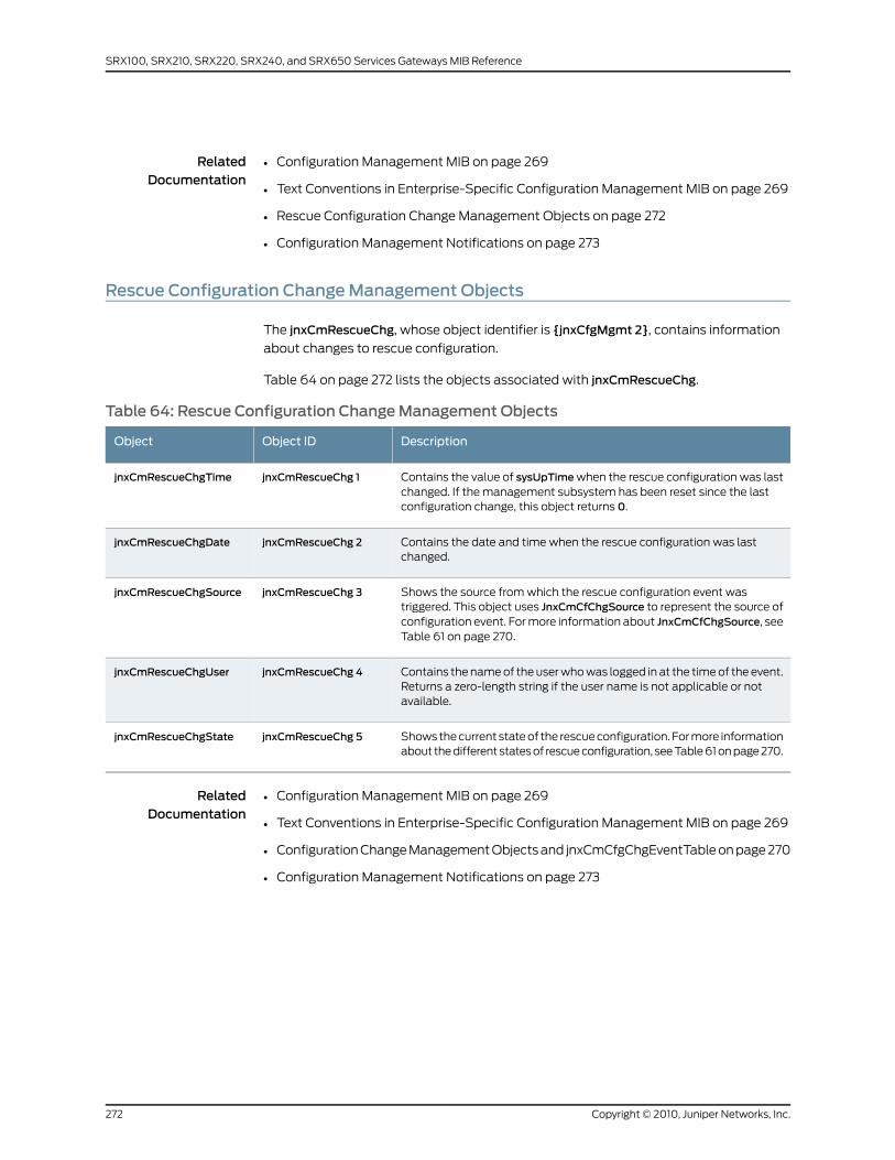
RelatedDocumentation
Configuration Management MIB on page 269•
• Text Conventions in Enterprise-Specific Configuration Management MIB on page 269
• Rescue Configuration Change Management Objects on page 272
• Configuration Management Notifications on page 273
Rescue Configuration ChangeManagement Objects
The jnxCmRescueChg, whose object identifier is {jnxCfgMgmt 2}, contains information
about changes to rescue configuration.
Table 64 on page 272 lists the objects associated with jnxCmRescueChg.
Table 64: Rescue Configuration ChangeManagement Objects
DescriptionObject IDObject
Contains the value of sysUpTimewhen the rescue configuration was lastchanged. If the management subsystem has been reset since the lastconfiguration change, this object returns 0.
jnxCmRescueChg 1jnxCmRescueChgTime
Contains the date and time when the rescue configuration was lastchanged.
jnxCmRescueChg 2jnxCmRescueChgDate
Shows the source from which the rescue configuration event wastriggered. This object uses JnxCmCfChgSource to represent the source ofconfiguration event. For more information about JnxCmCfChgSource, seeTable 61 on page 270.
jnxCmRescueChg 3jnxCmRescueChgSource
Contains the name of the user who was logged in at the time of the event.Returns a zero-length string if the user name is not applicable or notavailable.
jnxCmRescueChg 4jnxCmRescueChgUser
Shows the current state of the rescue configuration. For more informationabout the different states of rescue configuration, see Table 61 on page 270.
jnxCmRescueChg 5jnxCmRescueChgState
RelatedDocumentation
Configuration Management MIB on page 269•
• Text Conventions in Enterprise-Specific Configuration Management MIB on page 269
• Configuration Change Management Objects and jnxCmCfgChgEventTable on page 270
• Configuration Management Notifications on page 273
Copyright © 2010, Juniper Networks, Inc.272
SRX100, SRX210, SRX220, SRX240, and SRX650 Services Gateways MIB Reference
ConfigurationManagement Notifications
Junos OS generates the following traps when a configuration or a rescue configuration
event occurs:
• jnxCmCfgChange, whose object identifier is {jnxCmNotificationsPrefix 1}, contains
jnxCmCfgChgEventTime, jnxCmCfgChgEventDate, jnxCmCfgChgEventSource,
jnxCmCfgChgEventUser, and jnxCmCfgChgEventLog.
NOTE: Because configuration rollback is handled by themastermanagementprocess thatuses the rootuser ID, the jnxCmCfgChgEventUser
object in the jnxCmCfgChange trap always returns root as the user name
for configuration rollback events.
• jnxCmRescueChange, whose object identifier is {jnxCmNotificationsPrefix 2}, contains
jnxCmRescueChgTime, jnxCmRescueChgDate, jnxCmRescueChgSource,
jnxCmRescueChgUser, and jnxCmRescueChgState.
RelatedDocumentation
• Configuration Management MIB on page 269
• Text Conventions in Enterprise-Specific Configuration Management MIB on page 269
• Configuration Change Management Objects and jnxCmCfgChgEventTable on page 270
• Rescue Configuration Change Management Objects on page 272
273Copyright © 2010, Juniper Networks, Inc.
Chapter 16: Interpreting the Enterprise-Specific Configuration Management MIB

Copyright © 2010, Juniper Networks, Inc.274
SRX100, SRX210, SRX220, SRX240, and SRX650 Services Gateways MIB Reference
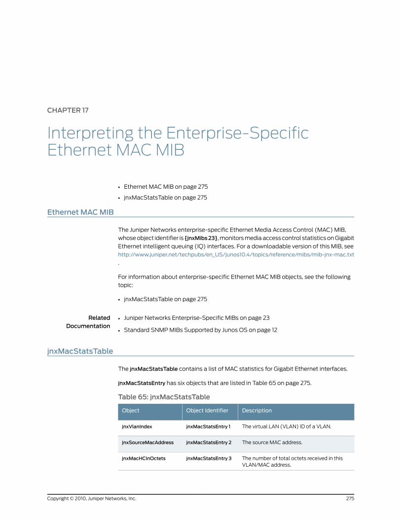
CHAPTER 17
Interpreting the Enterprise-SpecificEthernet MAC MIB
• Ethernet MAC MIB on page 275
• jnxMacStatsTable on page 275
Ethernet MACMIB
The Juniper Networks enterprise-specific Ethernet Media Access Control (MAC) MIB,
whose object identifier is {jnxMibs23}, monitors media access control statistics on Gigabit
Ethernet intelligent queuing (IQ) interfaces. For a downloadable version of this MIB, see
http://www.juniper.net/techpubs/en_US/junos10.4/topics/reference/mibs/mib-jnx-mac.txt
.
For information about enterprise-specific Ethernet MAC MIB objects, see the following
topic:
• jnxMacStatsTable on page 275
RelatedDocumentation
Juniper Networks Enterprise-Specific MIBs on page 23•
• Standard SNMP MIBs Supported by Junos OS on page 12
jnxMacStatsTable
The jnxMacStatsTable contains a list of MAC statistics for Gigabit Ethernet interfaces.
jnxMacStatsEntry has six objects that are listed in Table 65 on page 275.
Table 65: jnxMacStatsTable
DescriptionObject IdentifierObject
The virtual LAN (VLAN) ID of a VLAN.jnxMacStatsEntry 1jnxVlanIndex
The source MAC address.jnxMacStatsEntry 2jnxSourceMacAddress
The number of total octets received in thisVLAN/MAC address.
jnxMacStatsEntry 3jnxMacHCInOctets
275Copyright © 2010, Juniper Networks, Inc.
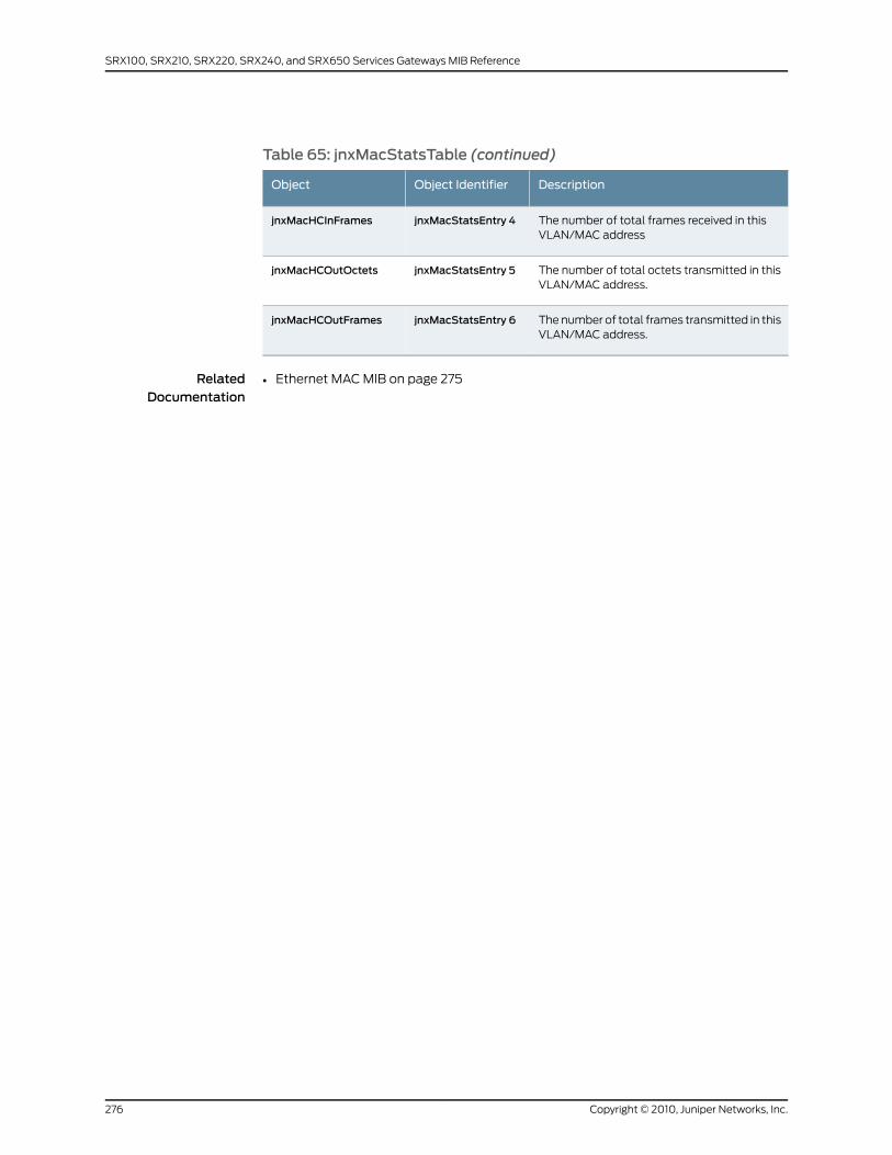
Table 65: jnxMacStatsTable (continued)
DescriptionObject IdentifierObject
The number of total frames received in thisVLAN/MAC address
jnxMacStatsEntry 4jnxMacHCInFrames
The number of total octets transmitted in thisVLAN/MAC address.
jnxMacStatsEntry 5jnxMacHCOutOctets
The number of total frames transmitted in thisVLAN/MAC address.
jnxMacStatsEntry 6jnxMacHCOutFrames
RelatedDocumentation
• Ethernet MAC MIB on page 275
Copyright © 2010, Juniper Networks, Inc.276
SRX100, SRX210, SRX220, SRX240, and SRX650 Services Gateways MIB Reference
CHAPTER 18
Interpreting the Enterprise-Specific EventMIB
• Event MIB on page 277
• jnxEventAvTable on page 277
• Notifications for the Event MIB on page 278
Event MIB
The Juniper Networks enterprise-specific Event MIB, whose object identifier is {jnxMibs37},
defines a generic trap that can be generated using an op script or event policy. This MIB
provides the ability to specify a system log string and raise a trap if that system log string
is found.
For a downloadable version of this MIB, see
http://www.juniper.net/techpubs/en_US/junos10.4/topics/reference/mibs/mib-jnx-event.txt
.
For information about the enterprise-specific Event MIB objects, see the following topics:
• jnxEventAvTable on page 277
• Notifications for the Event MIB on page 278
RelatedDocumentation
Juniper Networks Enterprise-Specific MIBs on page 23•
• Standard SNMP MIBs Supported by Junos OS on page 12
jnxEventAvTable
The jnxEventAvTable, whose object identifier is {jnxEventNotifyVars 2}, provides
information about traps generated by op scripts or event policies.
jnxEventAvEntry, whose object identifier is {jnxEventAvTable 1}, has three objects, which
are listed in Table 66 on page 278.
277Copyright © 2010, Juniper Networks, Inc.
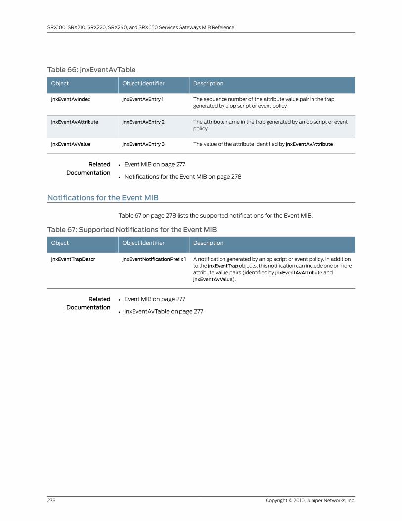
Table 66: jnxEventAvTable
DescriptionObject IdentifierObject
The sequence number of the attribute value pair in the trapgenerated by a op script or event policy
jnxEventAvEntry 1jnxEventAvIndex
The attribute name in the trap generated by an op script or eventpolicy
jnxEventAvEntry 2jnxEventAvAttribute
The value of the attribute identified by jnxEventAvAttributejnxEventAvEntry 3jnxEventAvValue
RelatedDocumentation
Event MIB on page 277•
• Notifications for the Event MIB on page 278
Notifications for the Event MIB
Table 67 on page 278 lists the supported notifications for the Event MIB.
Table 67: Supported Notifications for the Event MIB
DescriptionObject IdentifierObject
A notification generated by an op script or event policy. In additionto the jnxEventTrapobjects, this notification can include one or moreattribute value pairs (identified by jnxEventAvAttribute andjnxEventAvValue).
jnxEventNotificationPrefix 1jnxEventTrapDescr
RelatedDocumentation
• Event MIB on page 277
• jnxEventAvTable on page 277
Copyright © 2010, Juniper Networks, Inc.278
SRX100, SRX210, SRX220, SRX240, and SRX650 Services Gateways MIB Reference
CHAPTER 19
Interpreting the Enterprise-SpecificFirewall MIB
• Firewall MIB on page 279
• jnxFirewallsTable on page 280
• jnxFirewallCounterTable on page 280
Firewall MIB
The Juniper Networks enterprise-specific Firewall MIB, whose object identifier is {jnxMibs
5}, contains information about firewall filters and policies.
Firewall MIB contains two tables, jnxFirewallsTable and jnxFirewallCounterTable.
The jnxFirewallsTable does not support the following conditions:
• Counter and filter names that have more than 24 characters.
• Duplicate counter names, even if the counter types are different.
Because of the preceding limitations, the jnxFirewallsTable has been deprecated and
replaced with jnxFirewallCounterTable. However, for backward compatibility, the
jnxFirewallsTable is retained in the Firewall MIB.
For a downloadable version of the MIB, see
http://www.juniper.net/techpubs/en_US/junos10.4/topics/reference/mibs/mib-jnx-firewall.txt
For information about the enterprise-specific Firewall MIB objects, see the following
topics:
• jnxFirewallsTable on page 280
• jnxFirewallCounterTable on page 280
RelatedDocumentation
Juniper Networks Enterprise-Specific MIBs on page 23•
• Standard SNMP MIBs Supported by Junos OS on page 12
279Copyright © 2010, Juniper Networks, Inc.
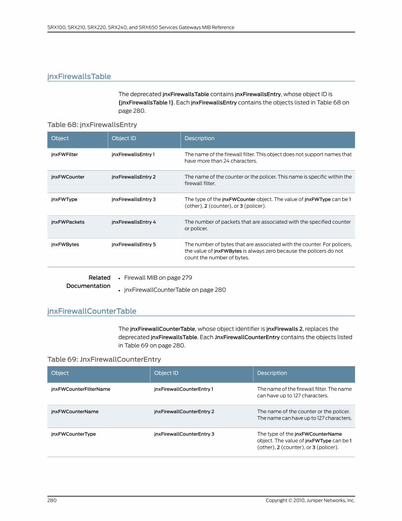
jnxFirewallsTable
The deprecated jnxFirewallsTable contains jnxFirewallsEntry, whose object ID is
{jnxFirewallsTable 1}. Each jnxFirewallsEntry contains the objects listed in Table 68 on
page 280.
Table 68: jnxFirewallsEntry
DescriptionObject IDObject
The name of the firewall filter. This object does not support names thathave more than 24 characters.
jnxFirewallsEntry 1jnxFWFilter
The name of the counter or the policer. This name is specific within thefirewall filter.
jnxFirewallsEntry 2jnxFWCounter
The type of the jnxFWCounter object. The value of jnxFWType can be 1(other), 2 (counter), or 3 (policer).
jnxFirewallsEntry 3jnxFWType
The number of packets that are associated with the specified counteror policer.
jnxFirewallsEntry 4jnxFWPackets
The number of bytes that are associated with the counter. For policers,the value of jnxFWBytes is always zero because the policers do notcount the number of bytes.
jnxFirewallsEntry 5jnxFWBytes
RelatedDocumentation
Firewall MIB on page 279•
• jnxFirewallCounterTable on page 280
jnxFirewallCounterTable
The jnxFirewallCounterTable, whose object identifier is jnxFirewalls 2, replaces the
deprecated jnxFirewallsTable. Each JnxFirewallCounterEntry contains the objects listed
in Table 69 on page 280.
Table 69: JnxFirewallCounterEntry
DescriptionObject IDObject
The name of the firewall filter. The namecan have up to 127 characters.
jnxFirewallCounterEntry 1jnxFWCounterFilterName
The name of the counter or the policer.The name can have up to 127 characters.
jnxFirewallCounterEntry 2jnxFWCounterName
The type of the jnxFWCounterNameobject. The value of jnxFWType can be 1(other), 2 (counter), or 3 (policer).
jnxFirewallCounterEntry 3jnxFWCounterType
Copyright © 2010, Juniper Networks, Inc.280
SRX100, SRX210, SRX220, SRX240, and SRX650 Services Gateways MIB Reference

Table 69: JnxFirewallCounterEntry (continued)
DescriptionObject IDObject
The number of packets that areassociated with the specified counter orpolicer.
jnxFirewallCounterEntry 4jnxFWCounterPacketCount
The number of bytes that are associatedwith the counter. For policers, the valueof jnxFWCounterByteCount is always zerobecause the policers do not count thenumber of bytes.
jnxFirewallCounterEntry 5jnxFWCounterByteCount
The name of the firewall filter. The namecan have up to 127 characters.
jnxFirewallCounterEntry 6jnxFWCounterDisplayFilterName
The name of the counter or the policer.jnxFirewallCounterEntry 7jnxFWCounterDisplayName
The type of the jnxFWCounterNameobject. The value of jnxFWType can be1 (other), 2 (counter), or 3 (policer).
jnxFirewallCounterEntry 8jnxFWCounterDisplayType
RelatedDocumentation
• Firewall MIB on page 279
• jnxFirewallsTable on page 280
281Copyright © 2010, Juniper Networks, Inc.
Chapter 19: Interpreting the Enterprise-Specific Firewall MIB

Copyright © 2010, Juniper Networks, Inc.282
SRX100, SRX210, SRX220, SRX240, and SRX650 Services Gateways MIB Reference
CHAPTER 20
Interpreting the Enterprise-Specific HostResources MIB
• Host Resources MIB on page 283
• jnxHrStorageTable on page 283
Host ResourcesMIB
The Juniper Networks enterprise-specific Host Resources MIB, whose object identifier is
{jnxMibs 31}, extends the hrStorageTable defined in RFC 2790, the standard Host
Resources MIB, to include the jnxHrStoragePercentUsed object.
For a downloadable version of this MIB, see
http://www.juniper.net/techpubs/en_US/junos10.4/topics/reference/mibs/mib-jnx-hostresources.txt
For information about the enterprise-specific Host Resources MIB objects, see the
following topic:
• jnxHrStorageTable on page 283
RelatedDocumentation
Juniper Networks Enterprise-Specific MIBs on page 23•
• Standard SNMP MIBs Supported by Junos OS on page 12
jnxHrStorageTable
The jnxHrStorageTable, whose object identifier is {jnxHrStorage 1}, contains
jnxHrStorageEntry. Each jnxHrStorageEntry augments the hrStorageEntry to provide
additional file system data, and contains the following object:
• jnxHrStoragePercentUsed—object identifier is {jnxHrStorageEntry 1}—Shows what
percentage of the total storage space has been used.
RelatedDocumentation
• Host Resources MIB on page 283
283Copyright © 2010, Juniper Networks, Inc.

Copyright © 2010, Juniper Networks, Inc.284
SRX100, SRX210, SRX220, SRX240, and SRX650 Services Gateways MIB Reference
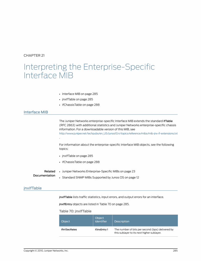
CHAPTER 21
Interpreting the Enterprise-SpecificInterface MIB
• Interface MIB on page 285
• jnxIfTable on page 285
• ifChassisTable on page 288
InterfaceMIB
The Juniper Networks enterprise-specific Interface MIB extends the standard ifTable
(RFC 2863) with additional statistics and Juniper Networks enterprise-specific chassis
information. For a downloadable version of this MIB, see
http://www.juniper.net/techpubs/en_US/junos10.4/topics/reference/mibs/mib-jnx-if-extensions.txt
.
For information about the enterprise-specific Interface MIB objects, see the following
topics:
• jnxIfTable on page 285
• ifChassisTable on page 288
RelatedDocumentation
Juniper Networks Enterprise-Specific MIBs on page 23•
• Standard SNMP MIBs Supported by Junos OS on page 12
jnxIfTable
jnxIfTable lists traffic statistics, input errors, and output errors for an interface.
jnxIfEntry objects are listed in Table 70 on page 285.
Table 70: jnxIfTable
DescriptionObjectIdentifierObject
The number of bits per second (bps) delivered bythis sublayer to its next higher sublayer.
ifJnxEntry 1ifIn1SecRates
285Copyright © 2010, Juniper Networks, Inc.

Table 70: jnxIfTable (continued)
DescriptionObjectIdentifierObject
The number of octets per second delivered by thissublayer to its next higher sublayer.
ifJnxEntry 2ifIn1SecOctets
The number of packets per second (pps) deliveredby this sublayer to its next higher sublayer.
ifJnxEntry 3ifIn1SecPkts
The number of bps delivered by this sublayer to itsnext lower sublayer.
ifJnxEntry 4ifOut1SecRate
The number of octets per second delivered by thissublayer to its next lower sublayer.
ifJnxEntry 5ifOut1SecOctets
The number of pps delivered by this sublayer to itsnext lower sublayer.
ifJnxEntry 6ifOut1SecPkts
The number of bps delivered by this sublayer to itsnext higher sublayer. This object is a 64-bit versionof ifIn1SecRate.
ifJnxEntry 7ifHCIn1SecRate
The number of bps delivered by this sublayer to itsnext lower sublayers. This object is a 64-bit versionof ifOut1SecRate.
ifJnxEntry 8ifHCOut1SecRate
Errors: The sum of the incoming frame aborts andFCS errors.
ifJnxEntry 9ifJnxInErrors
Framing Errors: The number of input packets thatwere misaligned.
ifJnxEntry 10ifJnxInFrameErrors
Drops: The number of packets dropped by the inputqueue of the I/O Manager ASIC.
ifJnxEntry 11ifJnxInQDrops
Runts: Frames received that are smaller than the runtthreshold.
ifJnxEntry 12ifJnxInRunts
Giants: Frames received that are larger than the giantthreshold.
ifJnxEntry 13ifJnxInGiants
Policed discards: Frames that the incoming packetmatch code discarded because they were notrecognized or of interest.
ifJnxEntry 14ifJnxInDiscards
HS link CRC errors: The number of CRC errors on thehigh-speed links between the ASICs responsible forhandling the router interfaces while receiving packets.
ifJnxEntry 15ifJnxInHslCrcErrors
HS link FIFO overflows: The number of FIFO overflowson the high-speed links between the ASICsresponsible for handling the router interfaces.
ifJnxEntry 16ifJnxInHslFifoOverFlows
Copyright © 2010, Juniper Networks, Inc.286
SRX100, SRX210, SRX220, SRX240, and SRX650 Services Gateways MIB Reference
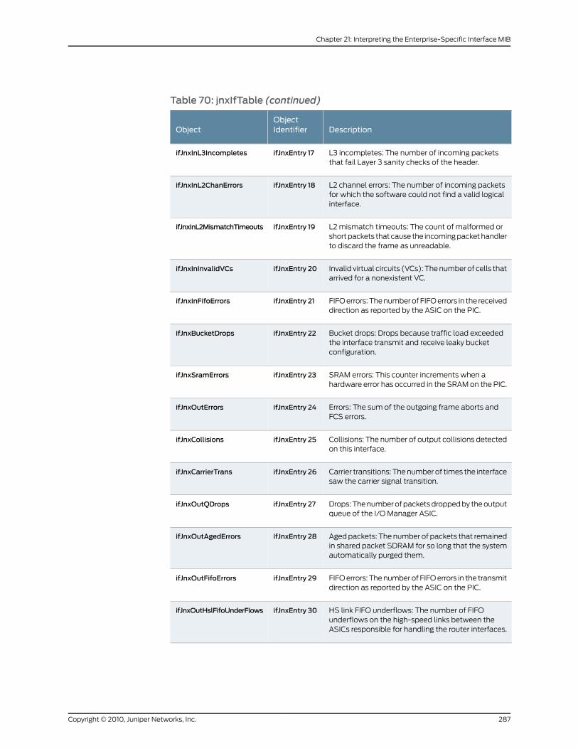
Table 70: jnxIfTable (continued)
DescriptionObjectIdentifierObject
L3 incompletes: The number of incoming packetsthat fail Layer 3 sanity checks of the header.
ifJnxEntry 17ifJnxInL3Incompletes
L2 channel errors: The number of incoming packetsfor which the software could not find a valid logicalinterface.
ifJnxEntry 18ifJnxInL2ChanErrors
L2 mismatch timeouts: The count of malformed orshort packets that cause the incoming packet handlerto discard the frame as unreadable.
ifJnxEntry 19ifJnxInL2MismatchTimeouts
Invalid virtual circuits (VCs): The number of cells thatarrived for a nonexistent VC.
ifJnxEntry 20ifJnxInInvalidVCs
FIFO errors: The number of FIFO errors in the receiveddirection as reported by the ASIC on the PIC.
ifJnxEntry 21ifJnxInFifoErrors
Bucket drops: Drops because traffic load exceededthe interface transmit and receive leaky bucketconfiguration.
ifJnxEntry 22ifJnxBucketDrops
SRAM errors: This counter increments when ahardware error has occurred in the SRAM on the PIC.
ifJnxEntry 23ifJnxSramErrors
Errors: The sum of the outgoing frame aborts andFCS errors.
ifJnxEntry 24ifJnxOutErrors
Collisions: The number of output collisions detectedon this interface.
ifJnxEntry 25ifJnxCollisions
Carrier transitions: The number of times the interfacesaw the carrier signal transition.
ifJnxEntry 26ifJnxCarrierTrans
Drops: The number of packets dropped by the outputqueue of the I/O Manager ASIC.
ifJnxEntry 27ifJnxOutQDrops
Aged packets: The number of packets that remainedin shared packet SDRAM for so long that the systemautomatically purged them.
ifJnxEntry 28ifJnxOutAgedErrors
FIFO errors: The number of FIFO errors in the transmitdirection as reported by the ASIC on the PIC.
ifJnxEntry 29ifJnxOutFifoErrors
HS link FIFO underflows: The number of FIFOunderflows on the high-speed links between theASICs responsible for handling the router interfaces.
ifJnxEntry 30ifJnxOutHslFifoUnderFlows
287Copyright © 2010, Juniper Networks, Inc.
Chapter 21: Interpreting the Enterprise-Specific Interface MIB
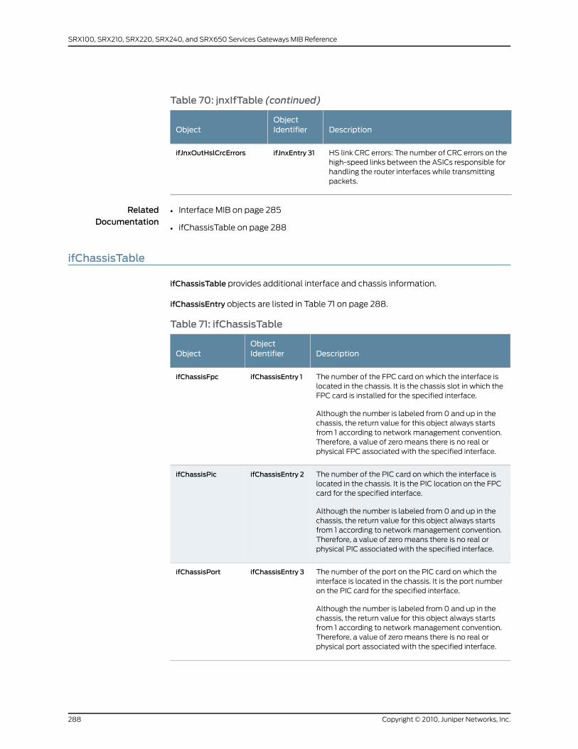
Table 70: jnxIfTable (continued)
DescriptionObjectIdentifierObject
HS link CRC errors: The number of CRC errors on thehigh-speed links between the ASICs responsible forhandling the router interfaces while transmittingpackets.
ifJnxEntry 31ifJnxOutHslCrcErrors
RelatedDocumentation
Interface MIB on page 285•
• ifChassisTable on page 288
ifChassisTable
ifChassisTable provides additional interface and chassis information.
ifChassisEntry objects are listed in Table 71 on page 288.
Table 71: ifChassisTable
DescriptionObjectIdentifierObject
The number of the FPC card on which the interface islocated in the chassis. It is the chassis slot in which theFPC card is installed for the specified interface.
Although the number is labeled from 0 and up in thechassis, the return value for this object always startsfrom 1 according to network management convention.Therefore, a value of zero means there is no real orphysical FPC associated with the specified interface.
ifChassisEntry 1ifChassisFpc
The number of the PIC card on which the interface islocated in the chassis. It is the PIC location on the FPCcard for the specified interface.
Although the number is labeled from 0 and up in thechassis, the return value for this object always startsfrom 1 according to network management convention.Therefore, a value of zero means there is no real orphysical PIC associated with the specified interface.
ifChassisEntry 2ifChassisPic
The number of the port on the PIC card on which theinterface is located in the chassis. It is the port numberon the PIC card for the specified interface.
Although the number is labeled from 0 and up in thechassis, the return value for this object always startsfrom 1 according to network management convention.Therefore, a value of zero means there is no real orphysical port associated with the specified interface.
ifChassisEntry 3ifChassisPort
Copyright © 2010, Juniper Networks, Inc.288
SRX100, SRX210, SRX220, SRX240, and SRX650 Services Gateways MIB Reference
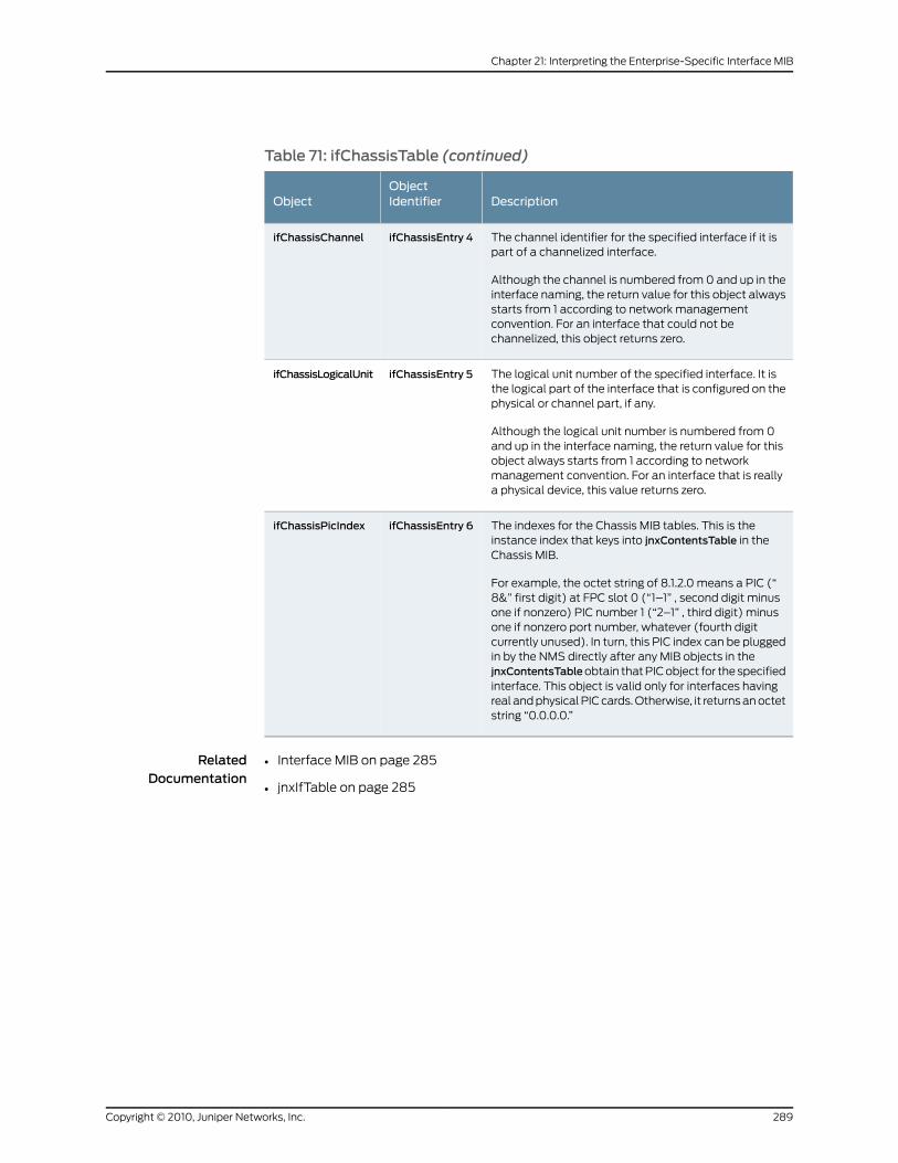
Table 71: ifChassisTable (continued)
DescriptionObjectIdentifierObject
The channel identifier for the specified interface if it ispart of a channelized interface.
Although the channel is numbered from 0 and up in theinterface naming, the return value for this object alwaysstarts from 1 according to network managementconvention. For an interface that could not bechannelized, this object returns zero.
ifChassisEntry 4ifChassisChannel
The logical unit number of the specified interface. It isthe logical part of the interface that is configured on thephysical or channel part, if any.
Although the logical unit number is numbered from 0and up in the interface naming, the return value for thisobject always starts from 1 according to networkmanagement convention. For an interface that is reallya physical device, this value returns zero.
ifChassisEntry 5ifChassisLogicalUnit
The indexes for the Chassis MIB tables. This is theinstance index that keys into jnxContentsTable in theChassis MIB.
For example, the octet string of 8.1.2.0 means a PIC (“8&” first digit) at FPC slot 0 (“1–1” , second digit minusone if nonzero) PIC number 1 (“2–1” , third digit) minusone if nonzero port number, whatever (fourth digitcurrently unused). In turn, this PIC index can be pluggedin by the NMS directly after any MIB objects in thejnxContentsTableobtain that PIC object for the specifiedinterface. This object is valid only for interfaces havingreal and physical PIC cards. Otherwise, it returns an octetstring “0.0.0.0.”
ifChassisEntry 6ifChassisPicIndex
RelatedDocumentation
• Interface MIB on page 285
• jnxIfTable on page 285
289Copyright © 2010, Juniper Networks, Inc.
Chapter 21: Interpreting the Enterprise-Specific Interface MIB

Copyright © 2010, Juniper Networks, Inc.290
SRX100, SRX210, SRX220, SRX240, and SRX650 Services Gateways MIB Reference
CHAPTER 22
Interpreting the Enterprise-Specific IPForward MIB
• IP Forward MIB on page 291
• jnxIpCidrRouteTable on page 292
IP ForwardMIB
The Juniper Networks enterprise-specific IP Forward MIB, whose object identifier is
{jnxMibs 38}, extends the ipCidrRouteTable in the IP Forwarding Table MIB (as defined
in RFC 2096) to include a tunnel name when the next hop is through an RSVP-signaled
LSP.
This MIB adds an jnxIpCidrRouteTunnelName attribute to the ipCidrRouteTable. The
attribute exists for each entry in the ipCidrRouteTable. (One entry in the ipCidrRouteTable
represents each route in inet.0). If the route's next hop is an RSVP-signaled MPLS LSP,
the new attribute contains the LSP name. If the route's next hop is not an RSVP-signaled
MPLS LSP, the new attribute is defined as null.
The attribute's name is jnxIpCidrRouteTunnelName. Its object identifier (OID) is
1.3.6.1.4.1.2636.3.38.1.1.1. As with any SNMP attribute, an index is appended to the OID to
form the instance identifier. Because this attribute augments the ipCidrRouteTable, the
index is identical to that used in the ipCidrRouteTable. The index is formed by
concatenating destination address, subnet mask, ToS byte, and next hop.
For a downloadable version of this MIB, see
http://www.juniper.net/techpubs/en_US/junos10.4/topics/reference/mibs/mib-jnx-ipforward.txt
.
For more information about the enterprise-specific IP Forward MIB, see
“jnxIpCidrRouteTable” on page 292.
RelatedDocumentation
Juniper Networks Enterprise-Specific MIBs on page 23•
• Standard SNMP MIBs Supported by Junos OS on page 12
291Copyright © 2010, Juniper Networks, Inc.
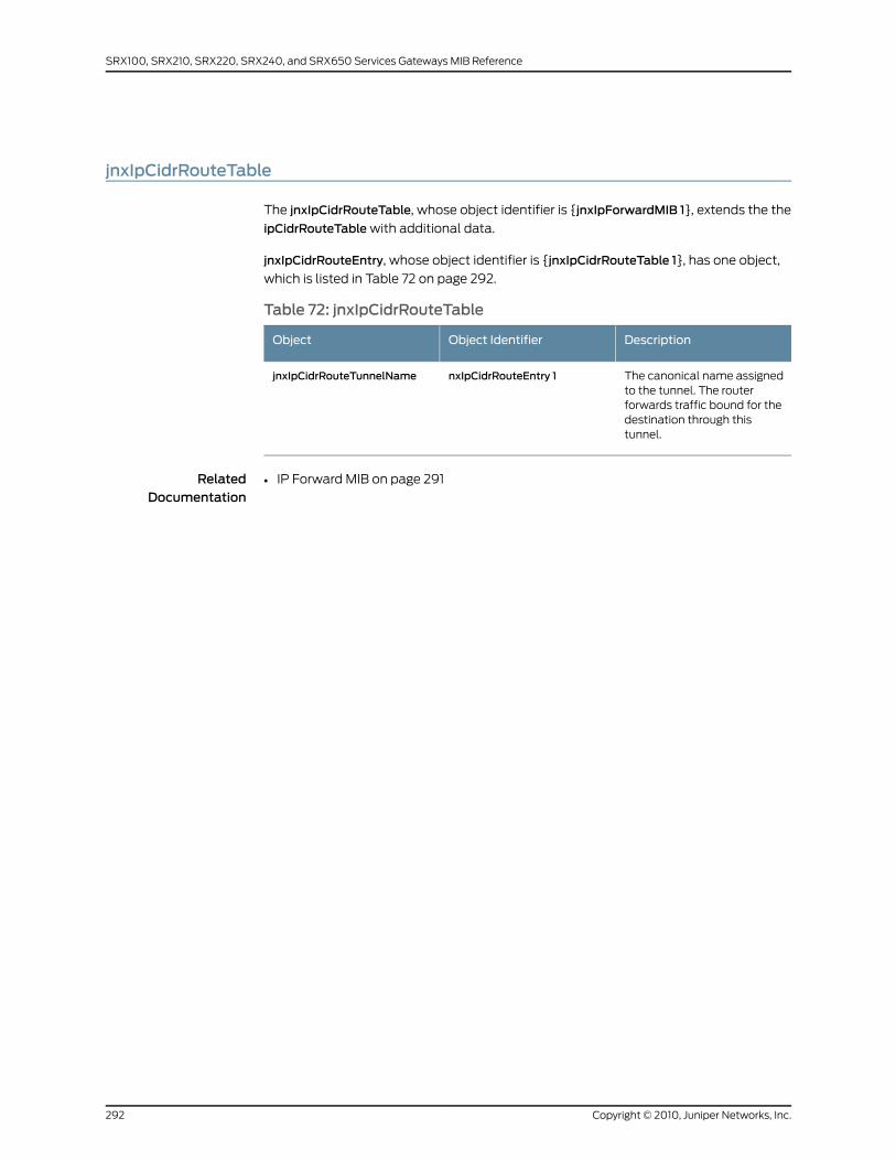
jnxIpCidrRouteTable
The jnxIpCidrRouteTable, whose object identifier is {jnxIpForwardMIB 1}, extends the the
ipCidrRouteTable with additional data.
jnxIpCidrRouteEntry, whose object identifier is {jnxIpCidrRouteTable 1}, has one object,
which is listed in Table 72 on page 292.
Table 72: jnxIpCidrRouteTable
DescriptionObject IdentifierObject
The canonical name assignedto the tunnel. The routerforwards traffic bound for thedestination through thistunnel.
nxIpCidrRouteEntry 1jnxIpCidrRouteTunnelName
RelatedDocumentation
• IP Forward MIB on page 291
Copyright © 2010, Juniper Networks, Inc.292
SRX100, SRX210, SRX220, SRX240, and SRX650 Services Gateways MIB Reference
CHAPTER 23
Interpreting the Enterprise-Specific IPsecGeneric Flow Monitoring Object MIB
• IPsec Generic Flow Monitoring Object MIB on page 293
• Branch Tree Objects on page 294
• Text Conventions on page 294
• Number of IKE Tunnels Currently Active on page 298
• IPsec Phase 1 IKE Tunnel Table on page 298
• IPsec Phase 2 IKE Tunnel Table on page 302
• IPsec Phase 2 Security Association Table on page 305
IPsec Generic FlowMonitoring Object MIB
The Juniper Networks enterprise-specific IPsec Generic Flow Monitoring Object MIB,
whose object ID is {jnxIpSecMibRoot 1}, defines the objects used to monitor the entries
pertaining to IPsec objects and the management of the IPsec VPN functionalities. This
generic MIB models the standard, dynamic aspects of IPsec, including the counters and
objects that are of management interest in a standard IPsec implementation.
This MIB module is based on the jnxIpSecMonitorMib. Building on the existing Internet
Key Exchange (IKE) infrastructure, the security IKE implementation integrates the
value-added features for the security products.
For a downloadable version of this MIB, see
http://www.juniper.net/techpubs/en_US/junos10.4/topics/reference/mibs/mib-jnx-ipsec-flow-mon.txt
.
For information about the enterprise-specific IPsec Flow Monitoring MIB objects, see the
following topics:
• Branch Tree Objects on page 294
• Text Conventions on page 294
• Number of IKE Tunnels Currently Active on page 298
• IPsec Phase 1 IKE Tunnel Table on page 298
293Copyright © 2010, Juniper Networks, Inc.
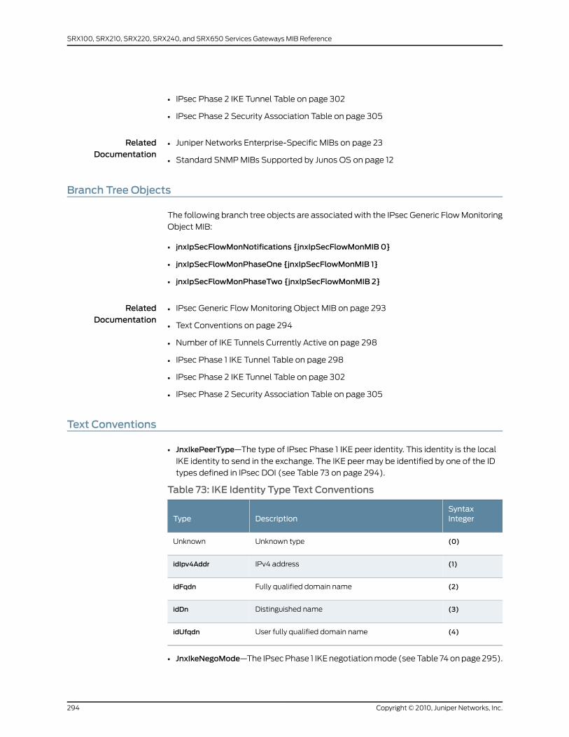
• IPsec Phase 2 IKE Tunnel Table on page 302
• IPsec Phase 2 Security Association Table on page 305
RelatedDocumentation
Juniper Networks Enterprise-Specific MIBs on page 23•
• Standard SNMP MIBs Supported by Junos OS on page 12
Branch Tree Objects
The following branch tree objects are associated with the IPsec Generic Flow Monitoring
Object MIB:
• jnxIpSecFlowMonNotifications {jnxIpSecFlowMonMIB 0}
• jnxIpSecFlowMonPhaseOne {jnxIpSecFlowMonMIB 1}
• jnxIpSecFlowMonPhaseTwo {jnxIpSecFlowMonMIB 2}
RelatedDocumentation
IPsec Generic Flow Monitoring Object MIB on page 293•
• Text Conventions on page 294
• Number of IKE Tunnels Currently Active on page 298
• IPsec Phase 1 IKE Tunnel Table on page 298
• IPsec Phase 2 IKE Tunnel Table on page 302
• IPsec Phase 2 Security Association Table on page 305
Text Conventions
• JnxIkePeerType—The type of IPsec Phase 1 IKE peer identity. This identity is the local
IKE identity to send in the exchange. The IKE peer may be identified by one of the ID
types defined in IPsec DOI (see Table 73 on page 294).
Table 73: IKE Identity Type Text Conventions
SyntaxIntegerDescriptionType
(0)Unknown typeUnknown
(1)IPv4 addressidIpv4Addr
(2)Fully qualified domain nameidFqdn
(3)Distinguished nameidDn
(4)User fully qualified domain nameidUfqdn
• JnxIkeNegoMode—The IPsec Phase 1 IKE negotiation mode (see Table 74 on page 295).
Copyright © 2010, Juniper Networks, Inc.294
SRX100, SRX210, SRX220, SRX240, and SRX650 Services Gateways MIB Reference
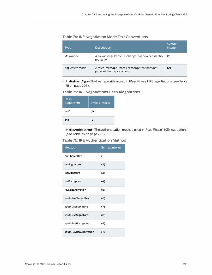
Table 74: IKE NegotiationMode Text Conventions
SyntaxIntegerDescriptionType
(1)A six-message Phase 1 exchange that provides identityprotection
Main mode
(2)A three-message Phase 1 exchange that does notprovide identity protection
Aggressive mode
• JnxIkeHashAlgo—The hash algorithm used in IPsec Phase 1 IKE negotiations (see Table
75 on page 295).
Table 75: IKE Negotiations Hash Alogorithms
Syntax IntegerHashAlogorithm
(1)md5
(2)sha
• JnxIkeAuthMethod—The authentication method used in IPsec Phase 1 IKE negotiations
(see Table 76 on page 295).
Table 76: IKE AuthenticationMethod
Syntax IntegerMethod
(1)preSharedKey
(2)dssSignature
(3)rsaSignature
(4)rsaEncryption
(5)revRsaEncryption
(6)xauthPreSharedKey
(7)xauthDssSignature
(8)xauthRsaSignature
(9)xauthRsaEncryption
(10)xauthRevRsaEncryption
295Copyright © 2010, Juniper Networks, Inc.
Chapter 23: Interpreting the Enterprise-Specific IPsec Generic Flow Monitoring Object MIB
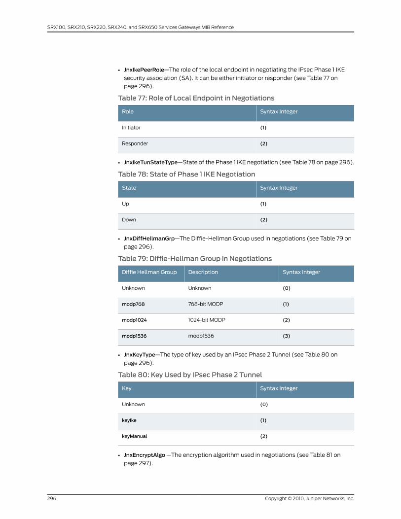
• JnxIkePeerRole—The role of the local endpoint in negotiating the IPsec Phase 1 IKE
security association (SA). It can be either initiator or responder (see Table 77 on
page 296).
Table 77: Role of Local Endpoint in Negotiations
Syntax IntegerRole
(1)Initiator
(2)Responder
• JnxIkeTunStateType—State of the Phase 1 IKE negotiation (see Table 78 on page 296).
Table 78: State of Phase 1 IKE Negotiation
Syntax IntegerState
(1)Up
(2)Down
• JnxDiffHellmanGrp—The Diffie-Hellman Group used in negotiations (see Table 79 on
page 296).
Table 79: Diffie-Hellman Group in Negotiations
Syntax IntegerDescriptionDiffie Hellman Group
(0)UnknownUnknown
(1)768-bit MODPmodp768
(2)1024-bit MODPmodp1024
(3)modp1536modp1536
• JnxKeyType—The type of key used by an IPsec Phase 2 Tunnel (see Table 80 on
page 296).
Table 80: Key Used by IPsec Phase 2 Tunnel
Syntax IntegerKey
(0)Unknown
(1)keyIke
(2)keyManual
• JnxEncryptAlgo—The encryption algorithm used in negotiations (see Table 81 on
page 297).
Copyright © 2010, Juniper Networks, Inc.296
SRX100, SRX210, SRX220, SRX240, and SRX650 Services Gateways MIB Reference
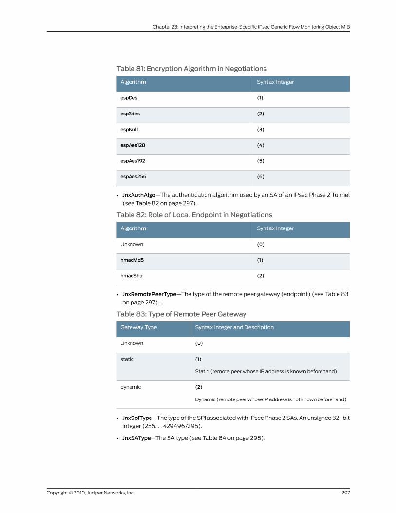
Table 81: Encryption Algorithm in Negotiations
Syntax IntegerAlgorithm
(1)espDes
(2)esp3des
(3)espNull
(4)espAes128
(5)espAes192
(6)espAes256
• JnxAuthAlgo—The authentication algorithm used by an SA of an IPsec Phase 2 Tunnel
(see Table 82 on page 297).
Table 82: Role of Local Endpoint in Negotiations
Syntax IntegerAlgorithm
(0)Unknown
(1)hmacMd5
(2)hmacSha
• JnxRemotePeerType—The type of the remote peer gateway (endpoint) (see Table 83
on page 297). .
Table 83: Type of Remote Peer Gateway
Syntax Integer and DescriptionGateway Type
(0)Unknown
(1)
Static (remote peer whose IP address is known beforehand)
static
(2)
Dynamic (remote peer whose IP address is not known beforehand)
dynamic
• JnxSpiType—The type of the SPI associated with IPsec Phase 2 SAs. An unsigned 32–bit
integer (256. . . 4294967295).
• JnxSAType—The SA type (see Table 84 on page 298).
297Copyright © 2010, Juniper Networks, Inc.
Chapter 23: Interpreting the Enterprise-Specific IPsec Generic Flow Monitoring Object MIB
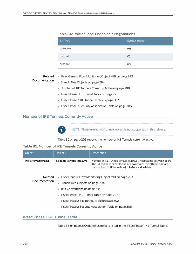
Table 84: Role of Local Endpoint in Negotiations
Syntax IntegerSA Type
(0)Unknown
(1)manual
(2)dynamic
RelatedDocumentation
IPsec Generic Flow Monitoring Object MIB on page 293•
• Branch Tree Objects on page 294
• Number of IKE Tunnels Currently Active on page 298
• IPsec Phase 1 IKE Tunnel Table on page 298
• IPsec Phase 2 IKE Tunnel Table on page 302
• IPsec Phase 2 Security Association Table on page 305
Number of IKE Tunnels Currently Active
NOTE: The jnxIkeNumOfTunnels object is not supported in this release.
Table 85 on page 298 reports the number of IKE Tunnels currently active.
Table 85: Number of IKE Tunnels Currently Active
DescriptionObject IDObject
Number of IKE Tunnels (Phase 1) actively negotiating between peers.The SA can be in either the up or down state. This attribute detailsthe number of IKE tunnels in jnxIkeTunnelMonTable.
jnxIpSecFlowMonPhaseOne1
jnxIkeNumOfTunnels
RelatedDocumentation
IPsec Generic Flow Monitoring Object MIB on page 293•
• Branch Tree Objects on page 294
• Text Conventions on page 294
• IPsec Phase 1 IKE Tunnel Table on page 298
• IPsec Phase 2 IKE Tunnel Table on page 302
• IPsec Phase 2 Security Association Table on page 305
IPsec Phase 1 IKE Tunnel Table
Table 86 on page 299 identifies objects listed in the IPsec Phase 1 IKE Tunnel Table.
Copyright © 2010, Juniper Networks, Inc.298
SRX100, SRX210, SRX220, SRX240, and SRX650 Services Gateways MIB Reference
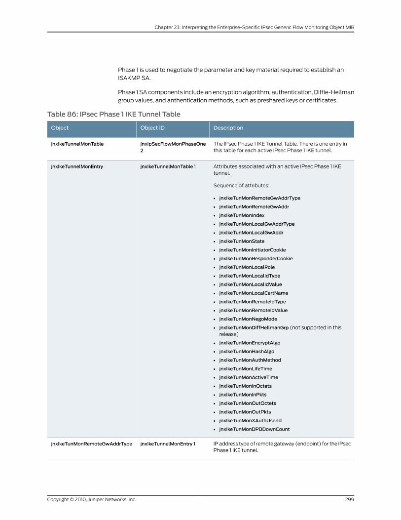
Phase 1 is used to negotiate the parameter and key material required to establish an
ISAKMP SA.
Phase 1 SA components include an encryption algorithm, authentication, Diffie-Hellman
group values, and anthentication methods, such as preshared keys or certificates.
Table 86: IPsec Phase 1 IKE Tunnel Table
DescriptionObject IDObject
The IPsec Phase 1 IKE Tunnel Table. There is one entry inthis table for each active IPsec Phase 1 IKE tunnel.
jnxIpSecFlowMonPhaseOne2
jnxIkeTunnelMonTable
Attributes associated with an active IPsec Phase 1 IKEtunnel.
Sequence of attributes:
• jnxIkeTunMonRemoteGwAddrType
• jnxIkeTunMonRemoteGwAddr
• jnxIkeTunMonIndex
• jnxIkeTunMonLocalGwAddrType
• jnxIkeTunMonLocalGwAddr
• jnxIkeTunMonState
• jnxIkeTunMonInitiatorCookie
• jnxIkeTunMonResponderCookie
• jnxIkeTunMonLocalRole
• jnxIkeTunMonLocalIdType
• jnxIkeTunMonLocalIdValue
• jnxIkeTunMonLocalCertName
• jnxIkeTunMonRemoteIdType
• jnxIkeTunMonRemoteIdValue
• jnxIkeTunMonNegoMode
• jnxIkeTunMonDiffHellmanGrp (not supported in thisrelease)
• jnxIkeTunMonEncryptAlgo
• jnxIkeTunMonHashAlgo
• jnxIkeTunMonAuthMethod
• jnxIkeTunMonLifeTime
• jnxIkeTunMonActiveTime
• jnxIkeTunMonInOctets
• jnxIkeTunMonInPkts
• jnxIkeTunMonOutOctets
• jnxIkeTunMonOutPkts
• jnxIkeTunMonXAuthUserId
• jnxIkeTunMonDPDDownCount
jnxIkeTunnelMonTable 1jnxIkeTunnelMonEntry
IP address type of remote gateway (endpoint) for the IPsecPhase 1 IKE tunnel.
jnxIkeTunnelMonEntry 1jnxIkeTunMonRemoteGwAddrType
299Copyright © 2010, Juniper Networks, Inc.
Chapter 23: Interpreting the Enterprise-Specific IPsec Generic Flow Monitoring Object MIB

Table 86: IPsec Phase 1 IKE Tunnel Table (continued)
DescriptionObject IDObject
IP address of remote gateway (endpoint) for the IPsecPhase 1 IKE tunnel.
jnxJsAuthTrapVars 4jnxJsFwAuthClientIpAddr
Index number of IPsec Phase 1 IKE Tunnel Table. The indexnumber begins at 1 and is incremented with each tunnelthat is created. The value of this object will wrap at2,147,483,647.
jnxIkeTunnelMonEntry 3jnxIkeTunMonIndex
IP address of local endpoint (gateway) for the IPsec Phase1 IKE tunnel.
jnxIkeTunnelMonEntry 4jnxIkeTunMonLocalGwAddr
IP address type of local endpoint (gateway) for the IPsecPhase 1 IKE tunnel.
jnxIkeTunnelMonEntry 5jnxIkeTunMonLocalGwAddrType
State of IKE tunnel. It can be:
• 1—up, negotiation completed.
• 2—down, being negotiated.
jnxIkeTunnelMonEntry 6jnxIkeTunMonState
Cookie as generated by peer that initiated the IKE Phase 1negotiation. This cookie is carried in the ISAKMP header.
jnxIkeTunnelMonEntry 7jnxIkeTunMonInitiatorCookie
Cookie as generated by peer responding to the IKE Phase1 negotiation initiated by the remote peer. This cookie iscarried in the ISAKMP header.
jnxIkeTunnelMonEntry 8jnxIkeTunMonResponderCookie
Role of local peer identity. The role of the local peer canbe:
• Initiator
• Responder
jnxIkeTunnelMonEntry 9jnxIkeTunMonLocalRole
Type of local peer identity. The local peer can be identifiedby:
• IP address.
• Fully qualified domain name string.
• Distinguished name string.
jnxIkeTunnelMonEntry 10jnxIkeTunMonLocalIdType
Value of local peer identity.
If the local peer type is an IP address, then this is the IPaddress used to identify the local peer.
If the local peer type is a fully qualified domain name string,then this is the fully qualified domain name string of thelocal peer.
If the local peer type is a distinguished name string, thenthis is the distinguished name string of the local peer.
jnxIkeTunnelMonEntry 11jnxIkeTunMonLocalIdValue
Copyright © 2010, Juniper Networks, Inc.300
SRX100, SRX210, SRX220, SRX240, and SRX650 Services Gateways MIB Reference
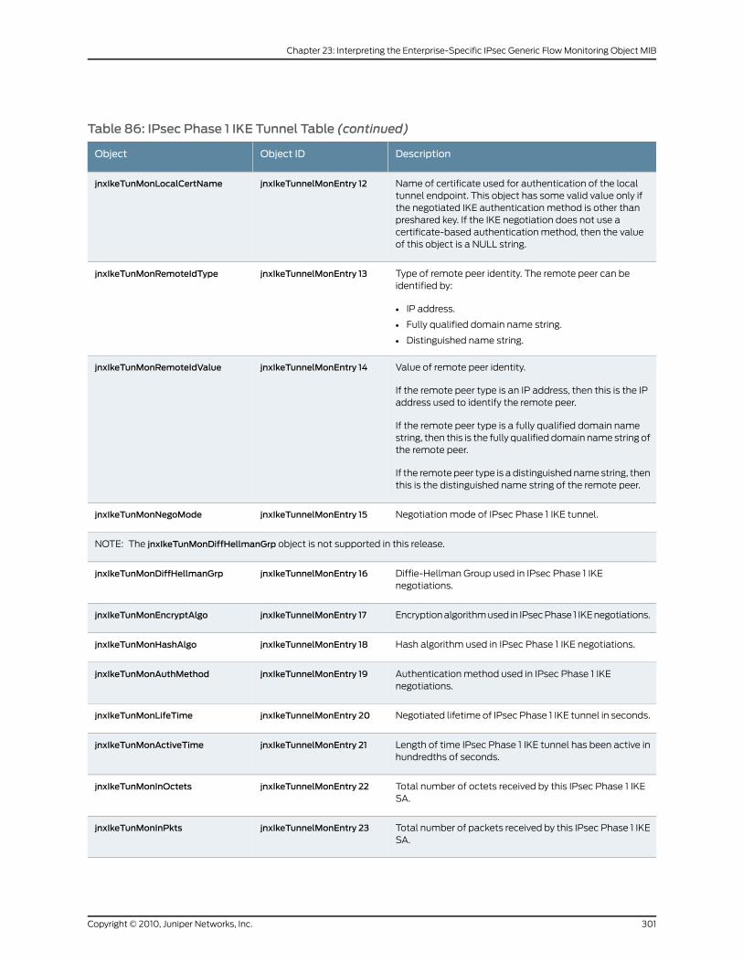
Table 86: IPsec Phase 1 IKE Tunnel Table (continued)
DescriptionObject IDObject
Name of certificate used for authentication of the localtunnel endpoint. This object has some valid value only ifthe negotiated IKE authentication method is other thanpreshared key. If the IKE negotiation does not use acertificate-based authentication method, then the valueof this object is a NULL string.
jnxIkeTunnelMonEntry 12jnxIkeTunMonLocalCertName
Type of remote peer identity. The remote peer can beidentified by:
• IP address.
• Fully qualified domain name string.
• Distinguished name string.
jnxIkeTunnelMonEntry 13jnxIkeTunMonRemoteIdType
Value of remote peer identity.
If the remote peer type is an IP address, then this is the IPaddress used to identify the remote peer.
If the remote peer type is a fully qualified domain namestring, then this is the fully qualified domain name string ofthe remote peer.
If the remote peer type is a distinguished name string, thenthis is the distinguished name string of the remote peer.
jnxIkeTunnelMonEntry 14jnxIkeTunMonRemoteIdValue
Negotiation mode of IPsec Phase 1 IKE tunnel.jnxIkeTunnelMonEntry 15jnxIkeTunMonNegoMode
NOTE: The jnxIkeTunMonDiffHellmanGrp object is not supported in this release.
Diffie-Hellman Group used in IPsec Phase 1 IKEnegotiations.
jnxIkeTunnelMonEntry 16jnxIkeTunMonDiffHellmanGrp
Encryption algorithm used in IPsec Phase 1 IKE negotiations.jnxIkeTunnelMonEntry 17jnxIkeTunMonEncryptAlgo
Hash algorithm used in IPsec Phase 1 IKE negotiations.jnxIkeTunnelMonEntry 18jnxIkeTunMonHashAlgo
Authentication method used in IPsec Phase 1 IKEnegotiations.
jnxIkeTunnelMonEntry 19jnxIkeTunMonAuthMethod
Negotiated lifetime of IPsec Phase 1 IKE tunnel in seconds.jnxIkeTunnelMonEntry 20jnxIkeTunMonLifeTime
Length of time IPsec Phase 1 IKE tunnel has been active inhundredths of seconds.
jnxIkeTunnelMonEntry 21jnxIkeTunMonActiveTime
Total number of octets received by this IPsec Phase 1 IKESA.
jnxIkeTunnelMonEntry 22jnxIkeTunMonInOctets
Total number of packets received by this IPsec Phase 1 IKESA.
jnxIkeTunnelMonEntry 23jnxIkeTunMonInPkts
301Copyright © 2010, Juniper Networks, Inc.
Chapter 23: Interpreting the Enterprise-Specific IPsec Generic Flow Monitoring Object MIB
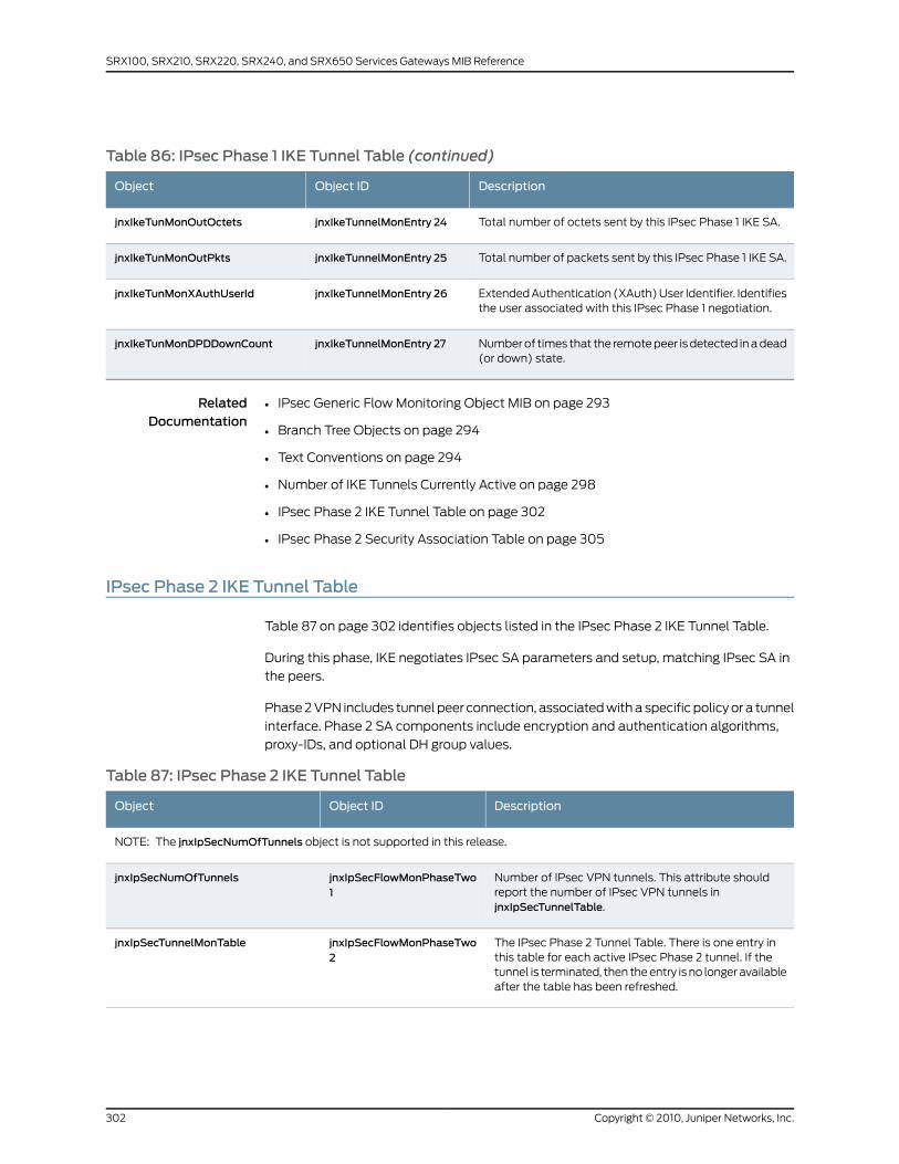
Table 86: IPsec Phase 1 IKE Tunnel Table (continued)
DescriptionObject IDObject
Total number of octets sent by this IPsec Phase 1 IKE SA.jnxIkeTunnelMonEntry 24jnxIkeTunMonOutOctets
Total number of packets sent by this IPsec Phase 1 IKE SA.jnxIkeTunnelMonEntry 25jnxIkeTunMonOutPkts
Extended Authentication (XAuth) User Identifier. Identifiesthe user associated with this IPsec Phase 1 negotiation.
jnxIkeTunnelMonEntry 26jnxIkeTunMonXAuthUserId
Number of times that the remote peer is detected in a dead(or down) state.
jnxIkeTunnelMonEntry 27jnxIkeTunMonDPDDownCount
RelatedDocumentation
IPsec Generic Flow Monitoring Object MIB on page 293•
• Branch Tree Objects on page 294
• Text Conventions on page 294
• Number of IKE Tunnels Currently Active on page 298
• IPsec Phase 2 IKE Tunnel Table on page 302
• IPsec Phase 2 Security Association Table on page 305
IPsec Phase 2 IKE Tunnel Table
Table 87 on page 302 identifies objects listed in the IPsec Phase 2 IKE Tunnel Table.
During this phase, IKE negotiates IPsec SA parameters and setup, matching IPsec SA in
the peers.
Phase 2 VPN includes tunnel peer connection, associated with a specific policy or a tunnel
interface. Phase 2 SA components include encryption and authentication algorithms,
proxy-IDs, and optional DH group values.
Table 87: IPsec Phase 2 IKE Tunnel Table
DescriptionObject IDObject
NOTE: The jnxIpSecNumOfTunnels object is not supported in this release.
Number of IPsec VPN tunnels. This attribute shouldreport the number of IPsec VPN tunnels injnxIpSecTunnelTable.
jnxIpSecFlowMonPhaseTwo1
jnxIpSecNumOfTunnels
The IPsec Phase 2 Tunnel Table. There is one entry inthis table for each active IPsec Phase 2 tunnel. If thetunnel is terminated, then the entry is no longer availableafter the table has been refreshed.
jnxIpSecFlowMonPhaseTwo2
jnxIpSecTunnelMonTable
Copyright © 2010, Juniper Networks, Inc.302
SRX100, SRX210, SRX220, SRX240, and SRX650 Services Gateways MIB Reference

Table 87: IPsec Phase 2 IKE Tunnel Table (continued)
DescriptionObject IDObject
Each entry contains the attributes associated with anactive IPsec Phase 2 tunnel.
Sequence of attributes:
• jnxIpSecTunMonRemoteGwAddrType
• jnxIpSecTunMonRemoteGwAddr
• jnxIpSecTunMonIndex
• jnxIpSecTunMonLocalGwAddrType
• jnxIpSecTunMonLocalGwAddr
• jnxIpSecTunMonLocalProxyId
• jnxIpSecTunMonRemoteProxyId
• jnxIpSecTunMonKeyType
• jnxIpSecTunMonRemotePeerType
• jnxIpSecTunMonOutEncryptedBytes
• jnxIpSecTunMonOutEncryptedPkts
• jnxIpSecTunMonInDecryptedBytes
• jnxIpSecTunMonInDecryptedPkts
• jnxIpSecTunMonAHInBytes
• jnxIpSecTunMonAHInPkts
• jnxIpSecTunMonAHOutBytes
• jnxIpSecTunMonAHOutPkts
• jnxIpSecTunMonReplayDropPkts
• jnxIpSecTunMonAhAuthFails
• jnxIpSecTunMonDecryptFails
• jnxIpSecTunMonBadHeaders
• jnxIpSecTunMonBadTrailers
• jnxIkeTunMonOutOctets
• jnxIpSecTunMonDroppedPkts (not supported in thisrelease)
jnxIpSecTunnelMonTable 1jnxIpSecTunnelMonEntry
IP address type of remote gateway (endpoint) for theIPsec Phase 2 tunnel.
jnxIpSecTunnelMonEntry 1jnxIpSecTunMonRemoteGwAddrType
IP address of remote gateway (endpoint) for the IPsecPhase 2 tunnel.
jnxIpSecTunnelMonEntry 2jnxIpSecTunMonRemoteGwAddr
Index number of IPsec Phase 2 Tunnel Table. The indexnumber begins at 1 and is incremented with each tunnelthat is created. The value of this object will wrap at2,147,483,647.
jnxIpSecTunnelMonEntry 3jnxIpSecTunMonIndex
IP address type of local gateway (endpoint) for the IPsecPhase 2 tunnel.
jnxIpSecTunnelMonEntry 4jnxIpSecTunMonLocalGwAddrType
IP address of local gateway (endpoint) for the IPsecPhase 2 tunnel.
jnxIpSecTunnelMonEntry 5jnxIpSecTunMonLocalGwAddr
303Copyright © 2010, Juniper Networks, Inc.
Chapter 23: Interpreting the Enterprise-Specific IPsec Generic Flow Monitoring Object MIB
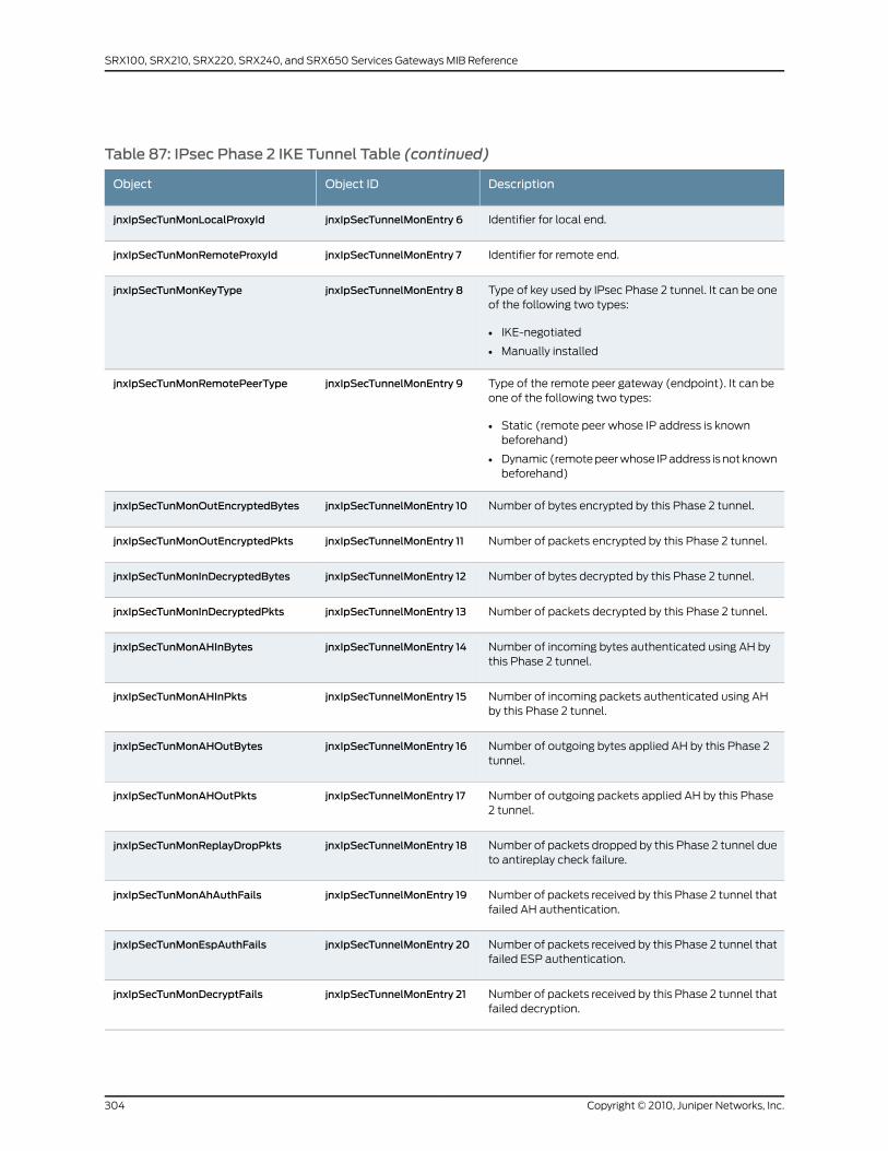
Table 87: IPsec Phase 2 IKE Tunnel Table (continued)
DescriptionObject IDObject
Identifier for local end.jnxIpSecTunnelMonEntry 6jnxIpSecTunMonLocalProxyId
Identifier for remote end.jnxIpSecTunnelMonEntry 7jnxIpSecTunMonRemoteProxyId
Type of key used by IPsec Phase 2 tunnel. It can be oneof the following two types:
• IKE-negotiated
• Manually installed
jnxIpSecTunnelMonEntry 8jnxIpSecTunMonKeyType
Type of the remote peer gateway (endpoint). It can beone of the following two types:
• Static (remote peer whose IP address is knownbeforehand)
• Dynamic (remote peer whose IP address is not knownbeforehand)
jnxIpSecTunnelMonEntry 9jnxIpSecTunMonRemotePeerType
Number of bytes encrypted by this Phase 2 tunnel.jnxIpSecTunnelMonEntry 10jnxIpSecTunMonOutEncryptedBytes
Number of packets encrypted by this Phase 2 tunnel.jnxIpSecTunnelMonEntry 11jnxIpSecTunMonOutEncryptedPkts
Number of bytes decrypted by this Phase 2 tunnel.jnxIpSecTunnelMonEntry 12jnxIpSecTunMonInDecryptedBytes
Number of packets decrypted by this Phase 2 tunnel.jnxIpSecTunnelMonEntry 13jnxIpSecTunMonInDecryptedPkts
Number of incoming bytes authenticated using AH bythis Phase 2 tunnel.
jnxIpSecTunnelMonEntry 14jnxIpSecTunMonAHInBytes
Number of incoming packets authenticated using AHby this Phase 2 tunnel.
jnxIpSecTunnelMonEntry 15jnxIpSecTunMonAHInPkts
Number of outgoing bytes applied AH by this Phase 2tunnel.
jnxIpSecTunnelMonEntry 16jnxIpSecTunMonAHOutBytes
Number of outgoing packets applied AH by this Phase2 tunnel.
jnxIpSecTunnelMonEntry 17jnxIpSecTunMonAHOutPkts
Number of packets dropped by this Phase 2 tunnel dueto antireplay check failure.
jnxIpSecTunnelMonEntry 18jnxIpSecTunMonReplayDropPkts
Number of packets received by this Phase 2 tunnel thatfailed AH authentication.
jnxIpSecTunnelMonEntry 19jnxIpSecTunMonAhAuthFails
Number of packets received by this Phase 2 tunnel thatfailed ESP authentication.
jnxIpSecTunnelMonEntry 20jnxIpSecTunMonEspAuthFails
Number of packets received by this Phase 2 tunnel thatfailed decryption.
jnxIpSecTunnelMonEntry 21jnxIpSecTunMonDecryptFails
Copyright © 2010, Juniper Networks, Inc.304
SRX100, SRX210, SRX220, SRX240, and SRX650 Services Gateways MIB Reference
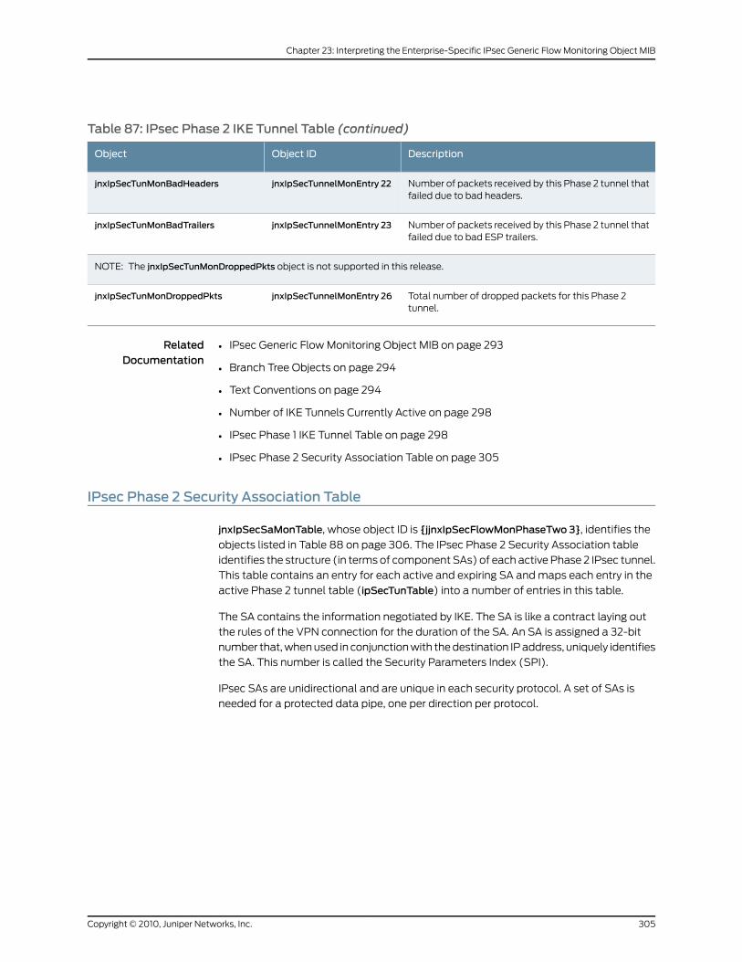
Table 87: IPsec Phase 2 IKE Tunnel Table (continued)
DescriptionObject IDObject
Number of packets received by this Phase 2 tunnel thatfailed due to bad headers.
jnxIpSecTunnelMonEntry 22jnxIpSecTunMonBadHeaders
Number of packets received by this Phase 2 tunnel thatfailed due to bad ESP trailers.
jnxIpSecTunnelMonEntry 23jnxIpSecTunMonBadTrailers
NOTE: The jnxIpSecTunMonDroppedPkts object is not supported in this release.
Total number of dropped packets for this Phase 2tunnel.
jnxIpSecTunnelMonEntry 26jnxIpSecTunMonDroppedPkts
RelatedDocumentation
IPsec Generic Flow Monitoring Object MIB on page 293•
• Branch Tree Objects on page 294
• Text Conventions on page 294
• Number of IKE Tunnels Currently Active on page 298
• IPsec Phase 1 IKE Tunnel Table on page 298
• IPsec Phase 2 Security Association Table on page 305
IPsec Phase 2 Security Association Table
jnxIpSecSaMonTable, whose object ID is {jjnxIpSecFlowMonPhaseTwo 3}, identifies the
objects listed in Table 88 on page 306. The IPsec Phase 2 Security Association table
identifies the structure (in terms of component SAs) of each active Phase 2 IPsec tunnel.
This table contains an entry for each active and expiring SA and maps each entry in the
active Phase 2 tunnel table (ipSecTunTable) into a number of entries in this table.
The SA contains the information negotiated by IKE. The SA is like a contract laying out
the rules of the VPN connection for the duration of the SA. An SA is assigned a 32-bit
number that, when used in conjunction with the destination IP address, uniquely identifies
the SA. This number is called the Security Parameters Index (SPI).
IPsec SAs are unidirectional and are unique in each security protocol. A set of SAs is
needed for a protected data pipe, one per direction per protocol.
305Copyright © 2010, Juniper Networks, Inc.
Chapter 23: Interpreting the Enterprise-Specific IPsec Generic Flow Monitoring Object MIB
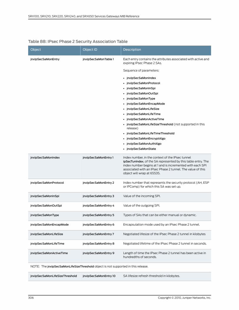
Table 88: IPsec Phase 2 Security Association Table
DescriptionObject IDObject
Each entry contains the attributes associated with active andexpiring IPsec Phase 2 SAs.
Sequence of parameters:
• jnxIpSecSaMonIndex
• jnxIpSecSaMonProtocol
• jnxIpSecSaMonInSpi
• jnxIpSecSaMonOutSpi
• jnxIpSecSaMonType
• jnxIpSecSaMonEncapMode
• jnxIpSecSaMonLifeSize
• jnxIpSecSaMonLifeTime
• jnxIpSecSaMonActiveTime
• jnxIpSecSaMonLifeSizeThreshold (not supported in thisrelease)
• jnxIpSecSaMonLifeTimeThreshold
• jnxIpSecSaMonEncryptAlgo
• jnxIpSecSaMonAuthAlgo
• jnxIpSecSaMonState
jnxIpSecSaMonTable 1jnxIpSecSaMonEntry
Index number, in the context of the IPsec tunnelipSecTunIndex, of the SA represented by this table entry. Theindex number begins at 1 and is incremented with each SPIassociated with an IPsec Phase 2 tunnel. The value of thisobject will wrap at 65535.
jnxIpSecSaMonEntry 1jnxIpSecSaMonIndex
Index number that represents the security protocol (AH, ESPor IPComp) for which this SA was set up.
jnxIpSecSaMonEntry 2jnxIpSecSaMonProtocol
Value of the incoming SPI.jnxIpSecSaMonEntry 3jnxIpSecSaMonInSpi
Value of the outgoing SPI.jnxIpSecSaMonEntry 4jnxIpSecSaMonOutSpi
Types of SAs that can be either manual or dynamic.jnxIpSecSaMonEntry 5jnxIpSecSaMonType
Encapsulation mode used by an IPsec Phase 2 tunnel.jnxIpSecSaMonEntry 6jnxIpSecSaMonEncapMode
Negotiated lifesize of the IPsec Phase 2 tunnel in kilobytesjnxIpSecSaMonEntry 7jnxIpSecSaMonLifeSize
Negotiated lifetime of the IPsec Phase 2 tunnel in seconds.jnxIpSecSaMonEntry 8jnxIpSecSaMonLifeTime
Length of time the IPsec Phase 2 tunnel has been active inhundredths of seconds.
jnxIpSecSaMonEntry 9jnxIpSecSaMonActiveTime
NOTE: The jnxIpSecSaMonLifeSizeThreshold object is not supported in this release.
SA lifesize refresh threshold in kilobytes.jnxIpSecSaMonEntry 10jnxIpSecSaMonLifeSizeThreshold
Copyright © 2010, Juniper Networks, Inc.306
SRX100, SRX210, SRX220, SRX240, and SRX650 Services Gateways MIB Reference
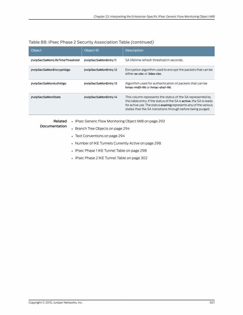
Table 88: IPsec Phase 2 Security Association Table (continued)
DescriptionObject IDObject
SA lifetime refresh threshold in seconds.jnxIpSecSaMonEntry 11jnxIpSecSaMonLifeTimeThreshold
Encryption algorithm used to encrypt the packets that can beeither es-cbc or 3des-cbc.
jnxIpSecSaMonEntry 12jnxIpSecSaMonEncryptAlgo
Algorithm used for authentication of packets that can behmac-md5-96 or hmac-sha1-96.
jnxIpSecSaMonEntry 13jnxIpSecSaMonAuthAlgo
This column represents the status of the SA represented bythis table entry. If the status of the SA is active, the SA is readyfor active use. The statusexpiring represents any of the variousstates that the SA transitions through before being purged.
jnxIpSecSaMonEntry 14jnxIpSecSaMonState
RelatedDocumentation
• IPsec Generic Flow Monitoring Object MIB on page 293
• Branch Tree Objects on page 294
• Text Conventions on page 294
• Number of IKE Tunnels Currently Active on page 298
• IPsec Phase 1 IKE Tunnel Table on page 298
• IPsec Phase 2 IKE Tunnel Table on page 302
307Copyright © 2010, Juniper Networks, Inc.
Chapter 23: Interpreting the Enterprise-Specific IPsec Generic Flow Monitoring Object MIB

Copyright © 2010, Juniper Networks, Inc.308
SRX100, SRX210, SRX220, SRX240, and SRX650 Services Gateways MIB Reference
CHAPTER 24
Interpreting the Enterprise-Specific IPsecMonitoring MIB
• IPSec Monitoring MIB on page 309
• jnxIkeTunnelTable on page 309
• jnxIPSecTunnelTable on page 312
• jnxIPSecSaTable on page 315
IPSecMonitoringMIB
The Juniper Networks enterprise-specific IPsec Monitoring MIB, whose object identifier
is {jnxMibs 22}, provides operational and statistical information related to the IPsec and
Internet Key Exchange (IKE) tunnels on Juniper Networks routers. For a downloadable
version of this MIB, see
http://www.juniper.net/techpubs/en_US/junos10.4/topics/reference/mibs/mib-jnx-ipsec-monitor-asp.txt
.
For information about IPsec Monitoring MIB objects, see the following topics:
• jnxIkeTunnelTable on page 309
• jnxIPSecTunnelTable on page 312
• jnxIPSecSaTable on page 315
RelatedDocumentation
Juniper Networks Enterprise-Specific MIBs on page 23•
• Standard SNMP MIBs Supported by Junos OS on page 12
jnxIkeTunnelTable
The IKE tunnel table (jnxIkeTunnelTable), whose object identifier is {jnxIPSecPhaseOne
1}, is used to monitor the IKE security associations established with the remote peers.
The MIB variables in this table are used to display the IKE SA attributes and the SA
statistics. There is one entry for each IKE SA present.
The key for this table is the combination of a service set name, remote gateway address,
and the IKE tunnel index. The service set name is used from the jnxSpSvcSetTablewhich
309Copyright © 2010, Juniper Networks, Inc.
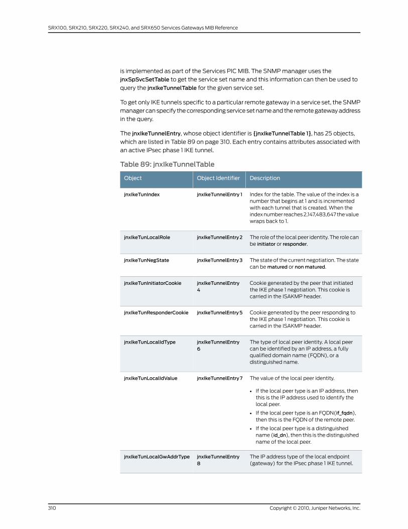
is implemented as part of the Services PIC MIB. The SNMP manager uses the
jnxSpSvcSetTable to get the service set name and this information can then be used to
query the jnxIkeTunnelTable for the given service set.
To get only IKE tunnels specific to a particular remote gateway in a service set, the SNMP
manager can specify the corresponding service set name and the remote gateway address
in the query.
The jnxIkeTunnelEntry, whose object identifier is {jnxIkeTunnelTable 1}, has 25 objects,
which are listed in Table 89 on page 310. Each entry contains attributes associated with
an active IPsec phase 1 IKE tunnel.
Table 89: jnxIkeTunnelTable
DescriptionObject IdentifierObject
Index for the table. The value of the index is anumber that begins at 1 and is incrementedwith each tunnel that is created. When theindex number reaches 2,147,483,647 the valuewraps back to 1.
jnxIkeTunnelEntry 1jnxIkeTunIndex
The role of the local peer identity. The role canbe initiator or responder.
jnxIkeTunnelEntry2jnxIkeTunLocalRole
The state of the current negotiation. The statecan be matured or nonmatured.
jnxIkeTunnelEntry3jnxIkeTunNegState
Cookie generated by the peer that initiatedthe IKE phase 1 negotiation. This cookie iscarried in the ISAKMP header.
jnxIkeTunnelEntry4
jnxIkeTunInitiatorCookie
Cookie generated by the peer responding tothe IKE phase 1 negotiation. This cookie iscarried in the ISAKMP header.
jnxIkeTunnelEntry5jnxIkeTunResponderCookie
The type of local peer identity. A local peercan be identified by an IP address, a fullyqualified domain name (FQDN), or adistinguished name.
jnxIkeTunnelEntry6
jnxIkeTunLocalIdType
The value of the local peer identity.
• If the local peer type is an IP address, thenthis is the IP address used to identify thelocal peer.
• If the local peer type is an FQDN(if_fqdn),then this is the FQDN of the remote peer.
• If the local peer type is a distinguishedname (id_dn), then this is the distinguishedname of the local peer.
jnxIkeTunnelEntry7jnxIkeTunLocalIdValue
The IP address type of the local endpoint(gateway) for the IPsec phase 1 IKE tunnel.
jnxIkeTunnelEntry8
jnxIkeTunLocalGwAddrType
Copyright © 2010, Juniper Networks, Inc.310
SRX100, SRX210, SRX220, SRX240, and SRX650 Services Gateways MIB Reference
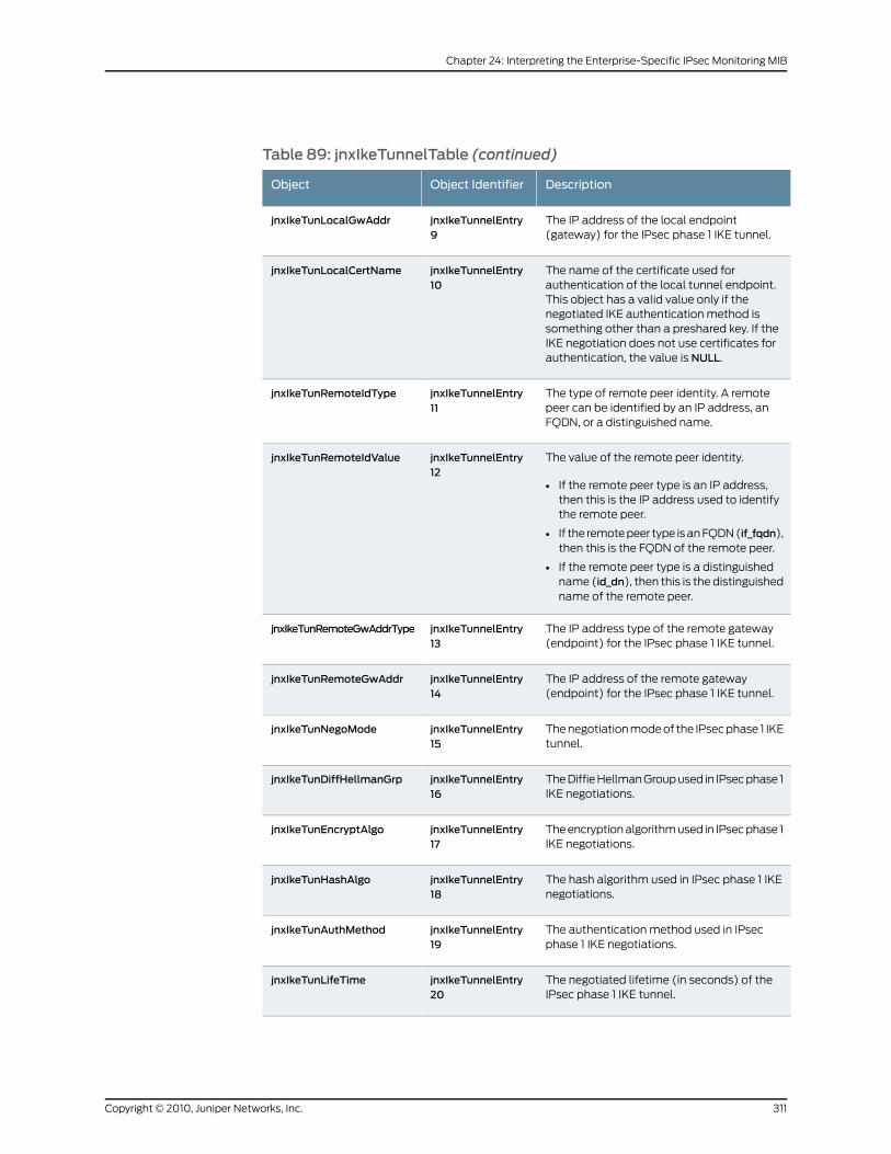
Table 89: jnxIkeTunnelTable (continued)
DescriptionObject IdentifierObject
The IP address of the local endpoint(gateway) for the IPsec phase 1 IKE tunnel.
jnxIkeTunnelEntry9
jnxIkeTunLocalGwAddr
The name of the certificate used forauthentication of the local tunnel endpoint.This object has a valid value only if thenegotiated IKE authentication method issomething other than a preshared key. If theIKE negotiation does not use certificates forauthentication, the value is NULL.
jnxIkeTunnelEntry10
jnxIkeTunLocalCertName
The type of remote peer identity. A remotepeer can be identified by an IP address, anFQDN, or a distinguished name.
jnxIkeTunnelEntry11
jnxIkeTunRemoteIdType
The value of the remote peer identity.
• If the remote peer type is an IP address,then this is the IP address used to identifythe remote peer.
• If the remote peer type is an FQDN (if_fqdn),then this is the FQDN of the remote peer.
• If the remote peer type is a distinguishedname (id_dn), then this is the distinguishedname of the remote peer.
jnxIkeTunnelEntry12
jnxIkeTunRemoteIdValue
The IP address type of the remote gateway(endpoint) for the IPsec phase 1 IKE tunnel.
jnxIkeTunnelEntry13
jnxIkeTunRemoteGwAddrType
The IP address of the remote gateway(endpoint) for the IPsec phase 1 IKE tunnel.
jnxIkeTunnelEntry14
jnxIkeTunRemoteGwAddr
The negotiation mode of the IPsec phase 1 IKEtunnel.
jnxIkeTunnelEntry15
jnxIkeTunNegoMode
The Diffie Hellman Group used in IPsec phase 1IKE negotiations.
jnxIkeTunnelEntry16
jnxIkeTunDiffHellmanGrp
The encryption algorithm used in IPsec phase 1IKE negotiations.
jnxIkeTunnelEntry17
jnxIkeTunEncryptAlgo
The hash algorithm used in IPsec phase 1 IKEnegotiations.
jnxIkeTunnelEntry18
jnxIkeTunHashAlgo
The authentication method used in IPsecphase 1 IKE negotiations.
jnxIkeTunnelEntry19
jnxIkeTunAuthMethod
The negotiated lifetime (in seconds) of theIPsec phase 1 IKE tunnel.
jnxIkeTunnelEntry20
jnxIkeTunLifeTime
311Copyright © 2010, Juniper Networks, Inc.
Chapter 24: Interpreting the Enterprise-Specific IPsec Monitoring MIB

Table 89: jnxIkeTunnelTable (continued)
DescriptionObject IdentifierObject
The length of time (in hundredths of seconds)that the IPsec phase 1 IKE tunnel has beenactive.
jnxIkeTunnelEntry21
jnxIkeTunActiveTime
The total number of octets received by thisIPsec phase 1 IKE security association.
jnxIkeTunnelEntry22
jnxIkeTunInOctets
The total number of packets received by thisIPsec phase 1 IKE security association.
jnxIkeTunnelEntry23
jnxIkeTunInPkts
The total number of octets sent by this IPsecphase 1 IKE security association.
jnxIkeTunnelEntry24
jnxIkeTunOutOcets
The total number of octets sent by this IPsecphase 1 IKE security association.
jnxIkeTunnelEntry25
jnxIkeTunOutPkts
RelatedDocumentation
IPSec Monitoring MIB on page 309•
• jnxIPSecTunnelTable on page 312
• jnxIPSecSaTable on page 315
jnxIPSecTunnelTable
The IPsec phase 2 tunnel table jnxIPSecTunnelTable), whose object identifier is
{jnxIPSecPhaseTwo 1}, is used to monitor the IPsec phase 2 tunnel attributes along with
the statistics for the tunnel. There is one entry for each tunnel to the peer security gateway.
This table does not contain information about IPsec security associations (SAs) because
multiple SAs can be present for each tunnel.
Similar to the IKE tunnel table (jnxIkeTunnelTable), the key of this table is a combination
of the service set name, remote gateway address, and the IPsec tunnel index. This table
can be queried just like the IKE tunnel table.
To get only IPsec tunnels specific to a particular remote gateway in a service set, the
SNMP manager can specify the corresponding service set name and the remote gateway
address in the query.
The jnxIPSecTunnelEntry, whose object identifier is {jnxIPSecTunnelTable 1}, has 27
objects, which are listed in Table 90 on page 313. Each entry contains attributes associated
with an active IPsec phase 2 tunnel.
Copyright © 2010, Juniper Networks, Inc.312
SRX100, SRX210, SRX220, SRX240, and SRX650 Services Gateways MIB Reference
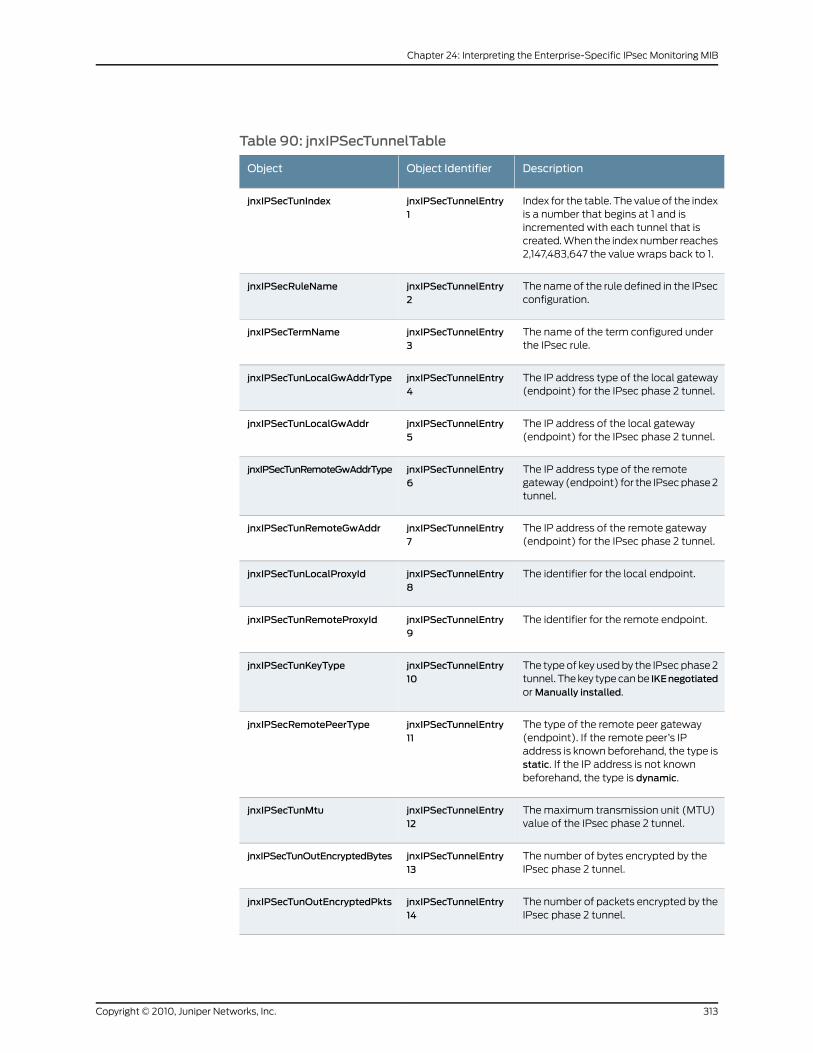
Table 90: jnxIPSecTunnelTable
DescriptionObject IdentifierObject
Index for the table. The value of the indexis a number that begins at 1 and isincremented with each tunnel that iscreated. When the index number reaches2,147,483,647 the value wraps back to 1.
jnxIPSecTunnelEntry1
jnxIPSecTunIndex
The name of the rule defined in the IPsecconfiguration.
jnxIPSecTunnelEntry2
jnxIPSecRuleName
The name of the term configured underthe IPsec rule.
jnxIPSecTunnelEntry3
jnxIPSecTermName
The IP address type of the local gateway(endpoint) for the IPsec phase 2 tunnel.
jnxIPSecTunnelEntry4
jnxIPSecTunLocalGwAddrType
The IP address of the local gateway(endpoint) for the IPsec phase 2 tunnel.
jnxIPSecTunnelEntry5
jnxIPSecTunLocalGwAddr
The IP address type of the remotegateway (endpoint) for the IPsec phase 2tunnel.
jnxIPSecTunnelEntry6
jnxIPSecTunRemoteGwAddrType
The IP address of the remote gateway(endpoint) for the IPsec phase 2 tunnel.
jnxIPSecTunnelEntry7
jnxIPSecTunRemoteGwAddr
The identifier for the local endpoint.jnxIPSecTunnelEntry8
jnxIPSecTunLocalProxyId
The identifier for the remote endpoint.jnxIPSecTunnelEntry9
jnxIPSecTunRemoteProxyId
The type of key used by the IPsec phase 2tunnel. The key type can be IKEnegotiatedor Manually installed.
jnxIPSecTunnelEntry10
jnxIPSecTunKeyType
The type of the remote peer gateway(endpoint). If the remote peer’s IPaddress is known beforehand, the type isstatic. If the IP address is not knownbeforehand, the type is dynamic.
jnxIPSecTunnelEntry11
jnxIPSecRemotePeerType
The maximum transmission unit (MTU)value of the IPsec phase 2 tunnel.
jnxIPSecTunnelEntry12
jnxIPSecTunMtu
The number of bytes encrypted by theIPsec phase 2 tunnel.
jnxIPSecTunnelEntry13
jnxIPSecTunOutEncryptedBytes
The number of packets encrypted by theIPsec phase 2 tunnel.
jnxIPSecTunnelEntry14
jnxIPSecTunOutEncryptedPkts
313Copyright © 2010, Juniper Networks, Inc.
Chapter 24: Interpreting the Enterprise-Specific IPsec Monitoring MIB
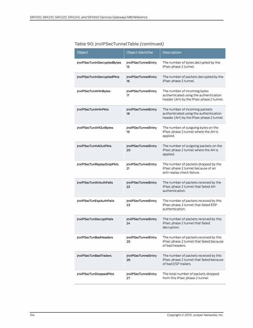
Table 90: jnxIPSecTunnelTable (continued)
DescriptionObject IdentifierObject
The number of bytes decrypted by theIPsec phase 2 tunnel.
jnxIPSecTunnelEntry15
jnxIPSecTunInDecryptedBytes
The number of packets decrypted by theIPsec phase 2 tunnel.
jnxIPSecTunnelEntry16
jnxIPSecTunInDecryptedPkts
The number of incoming bytesauthenticated using the authenticationheader (AH) by the IPsec phase 2 tunnel.
jnxIPSecTunnelEntry17
jnxIPSecTunAHInBytes
The number of incoming packetsauthenticated using the authenticationheader (AH) by the IPsec phase 2 tunnel.
jnxIPSecTunnelEntry18
jnxIPSecTunAHInPkts
The number of outgoing bytes on theIPsec phase 2 tunnel where the AH isapplied.
jnxIPSecTunnelEntry19
jnxIPSecTunAHOutBytes
The number of outgoing packets on theIPsec phase 2 tunnel where the AH isapplied.
jnxIPSecTunnelEntry20
jnxIPSecTunHAOutPkts
The number of packets dropped by theIPsec phase 2 tunnel because of ananti-replay check failure.
jnxIPSecTunnelEntry21
jnxIPSecTunReplayDropPkts
The number of packets received by theIPsec phase 2 tunnel that failed AHauthentication.
jnxIPSecTunnelEntry22
jnxIPSecTunAhAuthFails
The number of packets received by thisIPsec phase 2 tunnel that failed ESPauthentication.
jnxIPSecTunnelEntry23
jnxIPSecTunEspAuthFails
The number of packets received by thisIPsec phase 2 tunnel that faileddecryption.
jnxIPSecTunnelEntry24
jnxIPSecTunDecryptFails
The number of packets received by thisIPsec phase 2 tunnel that failed becauseof bad headers.
jnxIPSecTunnelEntry25
jnxIPSecTunBadHeaders
The number of packets received by thisIPsec phase 2 tunnel that failed becauseof bad ESP trailers.
jnxIPSecTunnelEntry26
jnxIPSecTunBadTrailers
The total number of packets droppedfrom this IPsec phase 2 tunnel.
jnxIPSecTunnelEntry27
jnxIPSecTunDroppedPkts
Copyright © 2010, Juniper Networks, Inc.314
SRX100, SRX210, SRX220, SRX240, and SRX650 Services Gateways MIB Reference
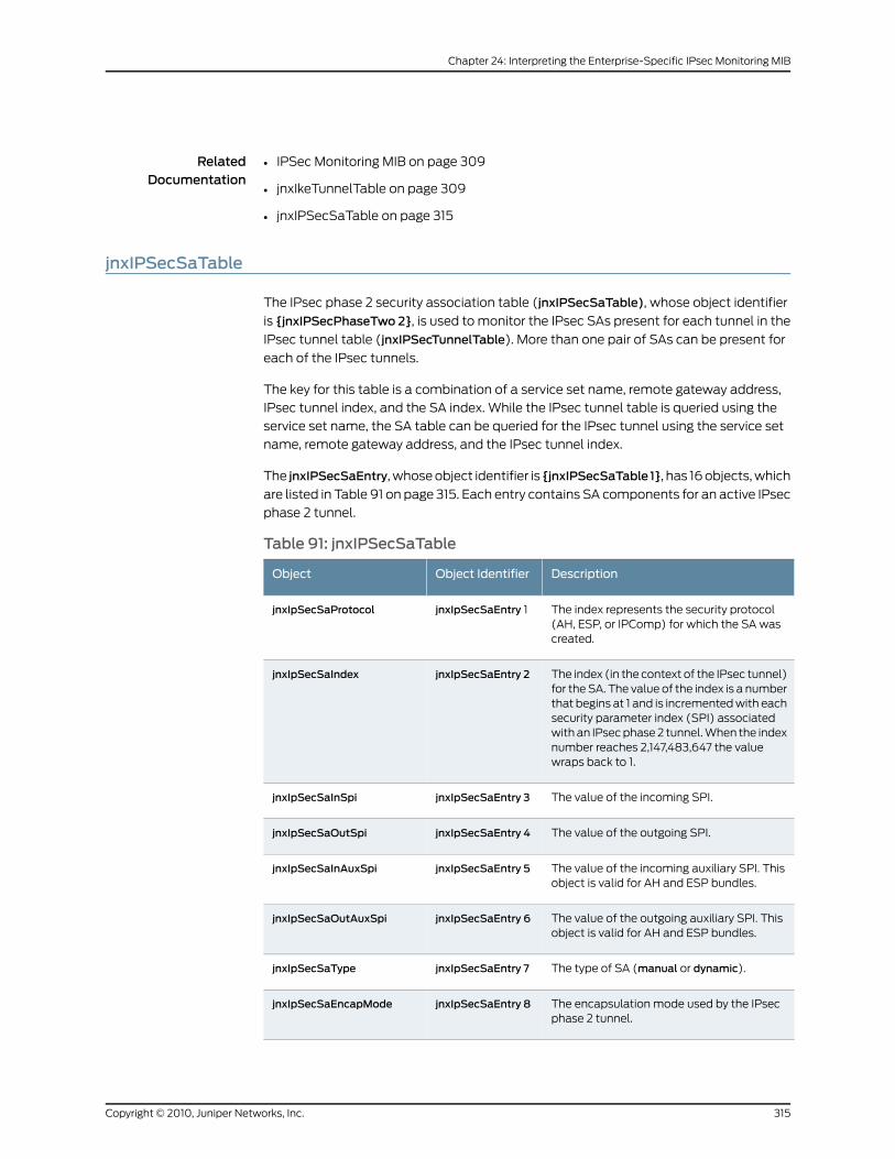
RelatedDocumentation
IPSec Monitoring MIB on page 309•
• jnxIkeTunnelTable on page 309
• jnxIPSecSaTable on page 315
jnxIPSecSaTable
The IPsec phase 2 security association table (jnxIPSecSaTable), whose object identifier
is {jnxIPSecPhaseTwo 2}, is used to monitor the IPsec SAs present for each tunnel in the
IPsec tunnel table (jnxIPSecTunnelTable). More than one pair of SAs can be present for
each of the IPsec tunnels.
The key for this table is a combination of a service set name, remote gateway address,
IPsec tunnel index, and the SA index. While the IPsec tunnel table is queried using the
service set name, the SA table can be queried for the IPsec tunnel using the service set
name, remote gateway address, and the IPsec tunnel index.
The jnxIPSecSaEntry, whose object identifier is {jnxIPSecSaTable 1}, has 16 objects, which
are listed in Table 91 on page 315. Each entry contains SA components for an active IPsec
phase 2 tunnel.
Table 91: jnxIPSecSaTable
DescriptionObject IdentifierObject
The index represents the security protocol(AH, ESP, or IPComp) for which the SA wascreated.
jnxIpSecSaEntry 1jnxIpSecSaProtocol
The index (in the context of the IPsec tunnel)for the SA. The value of the index is a numberthat begins at 1 and is incremented with eachsecurity parameter index (SPI) associatedwith an IPsec phase 2 tunnel. When the indexnumber reaches 2,147,483,647 the valuewraps back to 1.
jnxIpSecSaEntry 2jnxIpSecSaIndex
The value of the incoming SPI.jnxIpSecSaEntry 3jnxIpSecSaInSpi
The value of the outgoing SPI.jnxIpSecSaEntry 4jnxIpSecSaOutSpi
The value of the incoming auxiliary SPI. Thisobject is valid for AH and ESP bundles.
jnxIpSecSaEntry 5jnxIpSecSaInAuxSpi
The value of the outgoing auxiliary SPI. Thisobject is valid for AH and ESP bundles.
jnxIpSecSaEntry 6jnxIpSecSaOutAuxSpi
The type of SA (manual or dynamic).jnxIpSecSaEntry 7jnxIpSecSaType
The encapsulation mode used by the IPsecphase 2 tunnel.
jnxIpSecSaEntry 8jnxIpSecSaEncapMode
315Copyright © 2010, Juniper Networks, Inc.
Chapter 24: Interpreting the Enterprise-Specific IPsec Monitoring MIB
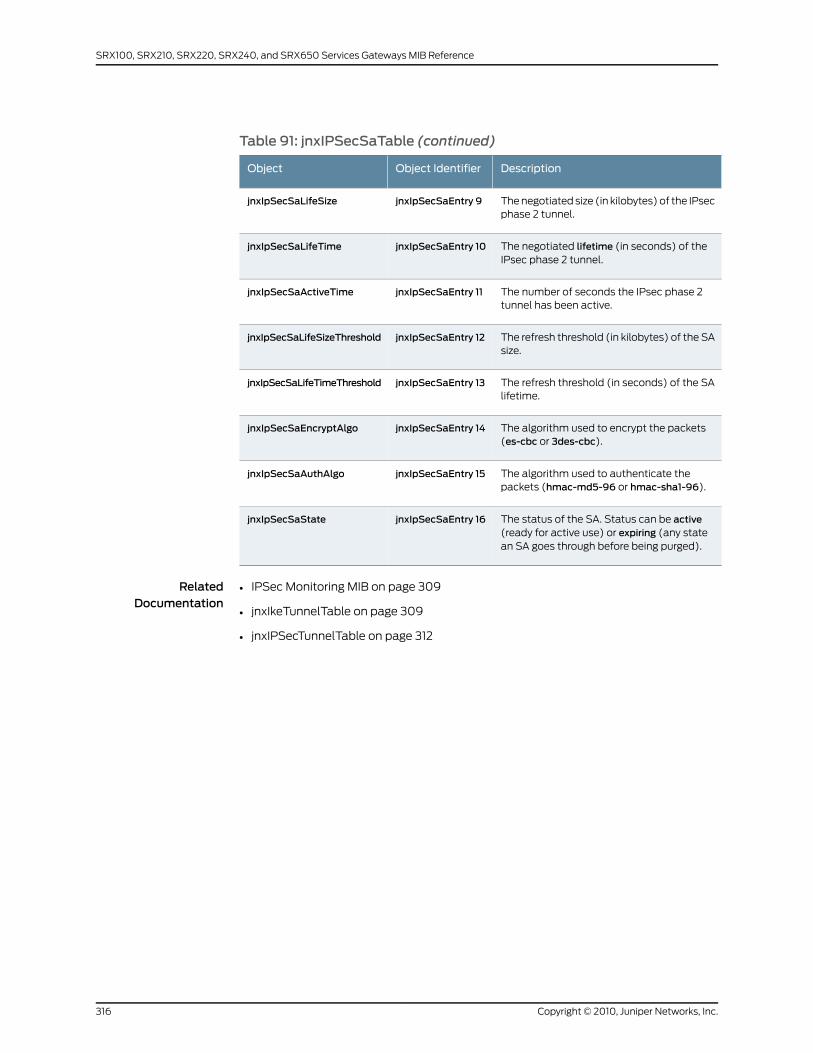
Table 91: jnxIPSecSaTable (continued)
DescriptionObject IdentifierObject
The negotiated size (in kilobytes) of the IPsecphase 2 tunnel.
jnxIpSecSaEntry 9jnxIpSecSaLifeSize
The negotiated lifetime (in seconds) of theIPsec phase 2 tunnel.
jnxIpSecSaEntry 10jnxIpSecSaLifeTime
The number of seconds the IPsec phase 2tunnel has been active.
jnxIpSecSaEntry 11jnxIpSecSaActiveTime
The refresh threshold (in kilobytes) of the SAsize.
jnxIpSecSaEntry 12jnxIpSecSaLifeSizeThreshold
The refresh threshold (in seconds) of the SAlifetime.
jnxIpSecSaEntry 13jnxIpSecSaLifeTimeThreshold
The algorithm used to encrypt the packets(es-cbc or 3des-cbc).
jnxIpSecSaEntry 14jnxIpSecSaEncryptAlgo
The algorithm used to authenticate thepackets (hmac-md5-96 or hmac-sha1-96).
jnxIpSecSaEntry 15jnxIpSecSaAuthAlgo
The status of the SA. Status can be active(ready for active use) or expiring (any statean SA goes through before being purged).
jnxIpSecSaEntry 16jnxIpSecSaState
RelatedDocumentation
• IPSec Monitoring MIB on page 309
• jnxIkeTunnelTable on page 309
• jnxIPSecTunnelTable on page 312
Copyright © 2010, Juniper Networks, Inc.316
SRX100, SRX210, SRX220, SRX240, and SRX650 Services Gateways MIB Reference
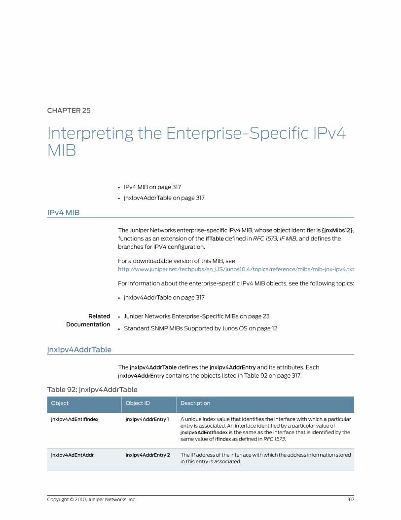
CHAPTER 25
Interpreting the Enterprise-Specific IPv4MIB
• IPv4 MIB on page 317
• jnxIpv4AddrTable on page 317
IPv4MIB
The Juniper Networks enterprise-specific IPv4 MIB, whose object identifier is {jnxMibs12},
functions as an extension of the ifTable defined in RFC 1573, IF MIB, and defines the
branches for IPV4 configuration.
For a downloadable version of this MIB, see
http://www.juniper.net/techpubs/en_US/junos10.4/topics/reference/mibs/mib-jnx-ipv4.txt
For information about the enterprise-specific IPv4 MIB objects, see the following topics:
• jnxIpv4AddrTable on page 317
RelatedDocumentation
Juniper Networks Enterprise-Specific MIBs on page 23•
• Standard SNMP MIBs Supported by Junos OS on page 12
jnxIpv4AddrTable
The jnxIpv4AddrTable defines the jnxIpv4AddrEntry and its attributes. Each
jnxIpv4AddrEntry contains the objects listed in Table 92 on page 317.
Table 92: jnxIpv4AddrTable
DescriptionObject IDObject
A unique index value that identifies the interface with which a particularentry is associated. An interface identified by a particular value ofjnxIpv4AdEntIfIndex is the same as the interface that is identified by thesame value of ifIndex as defined in RFC 1573.
jnxIpv4AddrEntry 1jnxIpv4AdEntIfIndex
The IP address of the interface with which the address information storedin this entry is associated.
jnxIpv4AddrEntry 2jnxIpv4AdEntAddr
317Copyright © 2010, Juniper Networks, Inc.
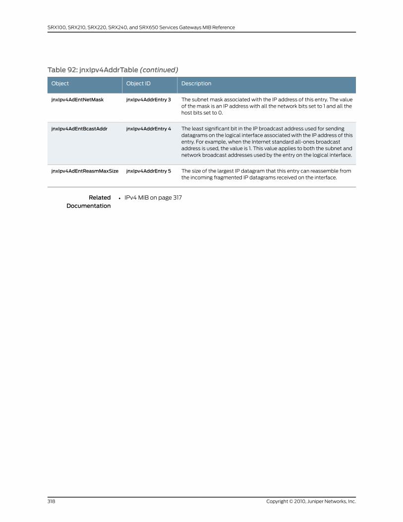
Table 92: jnxIpv4AddrTable (continued)
DescriptionObject IDObject
The subnet mask associated with the IP address of this entry. The valueof the mask is an IP address with all the network bits set to 1 and all thehost bits set to 0.
jnxIpv4AddrEntry 3jnxIpv4AdEntNetMask
The least significant bit in the IP broadcast address used for sendingdatagrams on the logical interface associated with the IP address of thisentry. For example, when the Internet standard all-ones broadcastaddress is used, the value is 1. This value applies to both the subnet andnetwork broadcast addresses used by the entry on the logical interface.
jnxIpv4AddrEntry 4jnxIpv4AdEntBcastAddr
The size of the largest IP datagram that this entry can reassemble fromthe incoming fragmented IP datagrams received on the interface.
jnxIpv4AddrEntry 5jnxIpv4AdEntReasmMaxSize
RelatedDocumentation
• IPv4 MIB on page 317
Copyright © 2010, Juniper Networks, Inc.318
SRX100, SRX210, SRX220, SRX240, and SRX650 Services Gateways MIB Reference

CHAPTER 26
Interpreting the Enterprise-Specific IPv6MIB
This chapter contains the following topics:
• IPv6 MIB Overview on page 319
• jnxIpv6GlobalStats on page 319
• jnxIcmpv6GlobalStats on page 322
IPv6MIB Overview
The Juniper Networks enterprise-specific IPv6 MIB, whose object identifier is { jnxMibs 11
}, functions as an extension of the ifTable defined in RFC 2465, IF MIB, and defines the
branches of IPv6 configuration.
For a downloadable version of the IPv6 MIB, see
http://www.juniper.net/techpubs/en_US/junos10.4/topics/reference/mibs/mib-jnx-ipv6.txt
.
For more information about the enterprise-specific IPv6 MIBs, see the following topics:
• jnxIpv6GlobalStats on page 319
• jnxIcmpv6GlobalStats on page 322
RelatedDocumentation
Standard SNMP MIBs Supported by Junos OS on page 12•
• Juniper Networks Enterprise-Specific MIBs on page 23
jnxIpv6GlobalStats
The jnxIpv6GlobalStats, whose object ID is { jnxIpv6Stats 1 }, represents the
jnxIpv6GlobalStats branch of IPv6 stats. Table 93 on page 319 identifies objects in the
jnxIpv6GlobalStats branch.
Table 93: jnxIpv6GlobalStats
DescriptionObject IDObject
The total number of IPv6 packets received.{ jnxIpv6GlobalStats 1 }jnxIpv6StatsReceives
319Copyright © 2010, Juniper Networks, Inc.
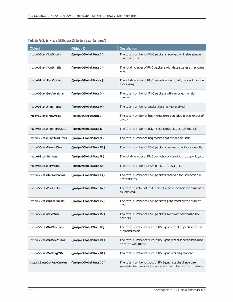
Table 93: jnxIpv6GlobalStats (continued)
DescriptionObject IDObject
The total number of IPv6 packets received with size smallerthan minimum.
{ jnxIpv6GlobalStats 2 }jnxIpv6StatsTooShorts
The total number of IPv6 packets with data size less than datalength.
{ jnxIpv6GlobalStats 3 }jnxIpv6StatsTooSmalls
The total number of IPv6 packets encountering errors in optionprocessing.
{ jnxIpv6GlobalStats 4}jnxIpv6StatsBadOptions
The total number of IPv6 packets with incorrect versionnumber.
{ jnxIpv6GlobalStats 5 }jnxIpv6StatsBadVersions
The total number of packet fragments received.{ jnxIpv6GlobalStats 6 }jnxIpv6StatsFragments
The total number of fragments dropped (duplicates or out ofpace).
{ jnxIpv6GlobalStats 7 }jnxIpv6StatsFragDrops
The total number of fragments dropped due to timeout.{ jnxIpv6GlobalStats 8 }jnxIpv6StatsFragTimeOuts
The total number of fragments that exceeded limit.{ jnxIpv6GlobalStats 9 }jnxIpv6StatsFragOverFlows
The total number of IPv6 packets reassembled successfully.{ jnxIpv6GlobalStats 10 }jnxIpv6StatsReasmOKs
The total number of IPv6 packets delivered to the upper layers.{ jnxIpv6GlobalStats 11 }jnxIpv6StatsDelivers
The total number of IPv6 packets forwarded.{ jnxIpv6GlobalStats 12 }jnxIpv6StatsForwards
The total number of IPv6 packets received for unreachabledestinations.
{ jnxIpv6GlobalStats 13 }jnxIpv6StatsUnreachables
The total number of IPv6 packets forwarded on the same netas received.
{ jnxIpv6GlobalStats 14 }jnxIpv6StatsRedirects
The total number of IPv6 packets generated by the currenthost.
{ jnxIpv6GlobalStats 15 }jnxIpv6StatsOutRequests
The total number of IPv6 packets sent with fabricated IPv6headers.
{ jnxIpv6GlobalStats 16 }jnxIpv6StatsRawOuts
The total number of output IPv6 packets dropped due to nobufs and so on.
{ jnxIpv6GlobalStats 17 }jnxIpv6StatsOutDiscards
The total number of output IPv6 packets discarded becauseno route was found.
{ jnxIpv6GlobalStats 18 }jnxIpv6StatsOutNoRoutes
The total number of output IPv6 packets fragmented.{ jnxIpv6GlobalStats 19 }jnxIpv6StatsOutFragOKs
The total number of output IPv6 packets that have beengenerated as a result of fragmentation at the output interface.
{ jnxIpv6GlobalStats 20 }jnxIpv6StatsOutFragCreates
Copyright © 2010, Juniper Networks, Inc.320
SRX100, SRX210, SRX220, SRX240, and SRX650 Services Gateways MIB Reference
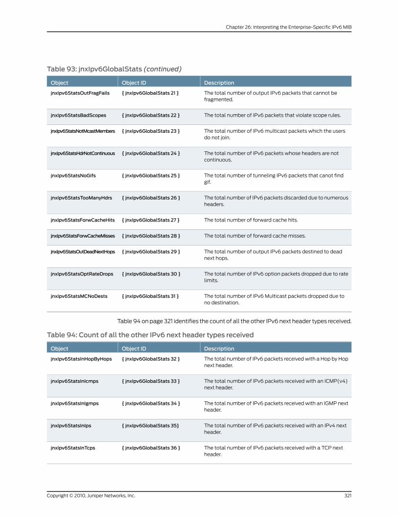
Table 93: jnxIpv6GlobalStats (continued)
DescriptionObject IDObject
The total number of output IPv6 packets that cannot befragmented.
{ jnxIpv6GlobalStats 21 }jnxIpv6StatsOutFragFails
The total number of IPv6 packets that violate scope rules.{ jnxIpv6GlobalStats 22 }jnxIpv6StatsBadScopes
The total number of IPv6 multicast packets which the usersdo not join.
{ jnxIpv6GlobalStats 23 }jnxIpv6StatsNotMcastMembers
The total number of IPv6 packets whose headers are notcontinuous.
{ jnxIpv6GlobalStats 24 }jnxIpv6StatsHdrNotContinuous
The total number of tunneling IPv6 packets that canot findgif.
{ jnxIpv6GlobalStats 25 }jnxIpv6StatsNoGifs
The total number of IPv6 packets discarded due to numerousheaders.
{ jnxIpv6GlobalStats 26 }jnxIpv6StatsTooManyHdrs
The total number of forward cache hits.{ jnxIpv6GlobalStats 27 }jnxIpv6StatsForwCacheHits
The total number of forward cache misses.{ jnxIpv6GlobalStats 28 }jnxIpv6StatsForwCacheMisses
The total number of output IPv6 packets destined to deadnext hops.
{ jnxIpv6GlobalStats 29 }jnxIpv6StatsOutDeadNextHops
The total number of IPv6 option packets dropped due to ratelimits.
{ jnxIpv6GlobalStats 30 }jnxIpv6StatsOptRateDrops
The total number of IPv6 Multicast packets dropped due tono destination.
{ jnxIpv6GlobalStats 31 }jnxIpv6StatsMCNoDests
Table 94 on page 321 identifies the count of all the other IPv6 next header types received.
Table 94: Count of all the other IPv6 next header types received
DescriptionObject IDObject
The total number of IPv6 packets received with a Hop by Hopnext header.
{ jnxIpv6GlobalStats 32 }jnxIpv6StatsInHopByHops
The total number of IPv6 packets received with an ICMP(v4)next header.
{ jnxIpv6GlobalStats 33 }jnxIpv6StatsInIcmps
The total number of IPv6 packets received with an IGMP nextheader.
{ jnxIpv6GlobalStats 34 }jnxIpv6StatsInIgmps
The total number of IPv6 packets received with an IPv4 nextheader.
{ jnxIpv6GlobalStats 35}jnxIpv6StatsInIps
The total number of IPv6 packets received with a TCP nextheader.
{ jnxIpv6GlobalStats 36 }jnxIpv6StatsInTcps
321Copyright © 2010, Juniper Networks, Inc.
Chapter 26: Interpreting the Enterprise-Specific IPv6 MIB
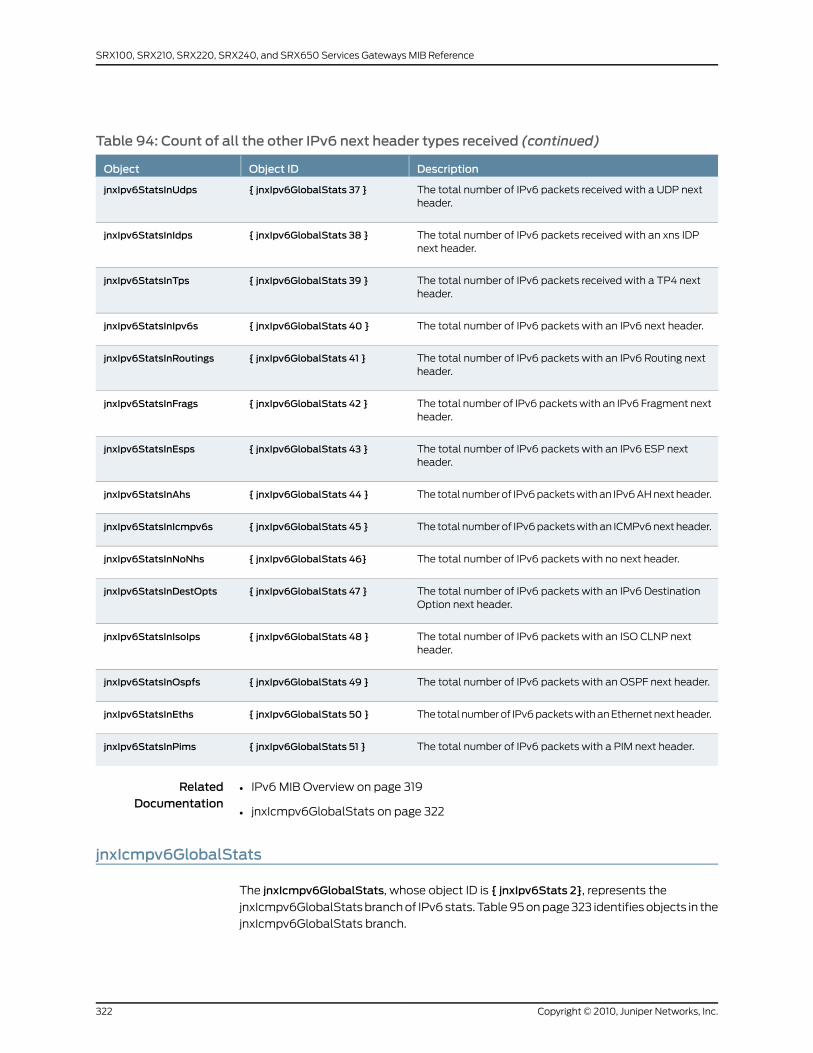
Table 94: Count of all the other IPv6 next header types received (continued)
DescriptionObject IDObject
The total number of IPv6 packets received with a UDP nextheader.
{ jnxIpv6GlobalStats 37 }jnxIpv6StatsInUdps
The total number of IPv6 packets received with an xns IDPnext header.
{ jnxIpv6GlobalStats 38 }jnxIpv6StatsInIdps
The total number of IPv6 packets received with a TP4 nextheader.
{ jnxIpv6GlobalStats 39 }jnxIpv6StatsInTps
The total number of IPv6 packets with an IPv6 next header.{ jnxIpv6GlobalStats 40 }jnxIpv6StatsInIpv6s
The total number of IPv6 packets with an IPv6 Routing nextheader.
{ jnxIpv6GlobalStats 41 }jnxIpv6StatsInRoutings
The total number of IPv6 packets with an IPv6 Fragment nextheader.
{ jnxIpv6GlobalStats 42 }jnxIpv6StatsInFrags
The total number of IPv6 packets with an IPv6 ESP nextheader.
{ jnxIpv6GlobalStats 43 }jnxIpv6StatsInEsps
The total number of IPv6 packets with an IPv6 AH next header.{ jnxIpv6GlobalStats 44 }jnxIpv6StatsInAhs
The total number of IPv6 packets with an ICMPv6 next header.{ jnxIpv6GlobalStats 45 }jnxIpv6StatsInIcmpv6s
The total number of IPv6 packets with no next header.{ jnxIpv6GlobalStats 46}jnxIpv6StatsInNoNhs
The total number of IPv6 packets with an IPv6 DestinationOption next header.
{ jnxIpv6GlobalStats 47 }jnxIpv6StatsInDestOpts
The total number of IPv6 packets with an ISO CLNP nextheader.
{ jnxIpv6GlobalStats 48 }jnxIpv6StatsInIsoIps
The total number of IPv6 packets with an OSPF next header.{ jnxIpv6GlobalStats 49 }jnxIpv6StatsInOspfs
The total number of IPv6 packets with an Ethernet next header.{ jnxIpv6GlobalStats 50 }jnxIpv6StatsInEths
The total number of IPv6 packets with a PIM next header.{ jnxIpv6GlobalStats 51 }jnxIpv6StatsInPims
RelatedDocumentation
IPv6 MIB Overview on page 319•
• jnxIcmpv6GlobalStats on page 322
jnxIcmpv6GlobalStats
The jnxIcmpv6GlobalStats, whose object ID is { jnxIpv6Stats 2}, represents the
jnxIcmpv6GlobalStats branch of IPv6 stats. Table 95 on page 323 identifies objects in the
jnxIcmpv6GlobalStats branch.
Copyright © 2010, Juniper Networks, Inc.322
SRX100, SRX210, SRX220, SRX240, and SRX650 Services Gateways MIB Reference
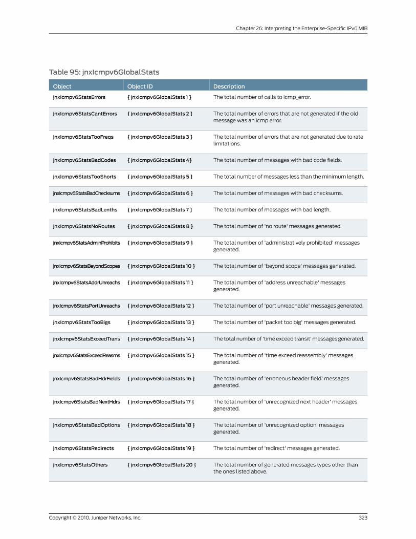
Table 95: jnxIcmpv6GlobalStats
DescriptionObject IDObject
The total number of calls to icmp_error.{ jnxIcmpv6GlobalStats 1 }jnxIcmpv6StatsErrors
The total number of errors that are not generated if the oldmessage was an icmp error.
{ jnxIcmpv6GlobalStats 2 }jnxIcmpv6StatsCantErrors
The total number of errors that are not generated due to ratelimitations.
{ jnxIcmpv6GlobalStats 3 }jnxIcmpv6StatsTooFreqs
The total number of messages with bad code fields.{ jnxIcmpv6GlobalStats 4}jnxIcmpv6StatsBadCodes
The total number of messages less than the minimum length.{ jnxIcmpv6GlobalStats 5 }jnxIcmpv6StatsTooShorts
The total number of messages with bad checksums.{ jnxIcmpv6GlobalStats 6 }jnxIcmpv6StatsBadChecksums
The total number of messages with bad length.{ jnxIcmpv6GlobalStats 7 }jnxIcmpv6StatsBadLenths
The total number of 'no route' messages generated.{ jnxIcmpv6GlobalStats 8 }jnxIcmpv6StatsNoRoutes
The total number of 'administratively prohibited' messagesgenerated.
{ jnxIcmpv6GlobalStats 9 }jnxIcmpv6StatsAdminProhibits
The total number of 'beyond scope' messages generated.{ jnxIcmpv6GlobalStats 10 }jnxIcmpv6StatsBeyondScopes
The total number of 'address unreachable' messagesgenerated.
{ jnxIcmpv6GlobalStats 11 }jnxIcmpv6StatsAddrUnreachs
The total number of 'port unreachable' messages generated.{ jnxIcmpv6GlobalStats 12 }jnxIcmpv6StatsPortUnreachs
The total number of 'packet too big' messages generated.{ jnxIcmpv6GlobalStats 13 }jnxIcmpv6StatsTooBigs
The total number of 'time exceed transit' messages generated.{ jnxIcmpv6GlobalStats 14 }jnxIcmpv6StatsExceedTrans
The total number of 'time exceed reassembly' messagesgenerated.
{ jnxIcmpv6GlobalStats 15 }jnxIcmpv6StatsExceedReasms
The total number of 'erroneous header field' messagesgenerated.
{ jnxIcmpv6GlobalStats 16 }jnxIcmpv6StatsBadHdrFields
The total number of 'unrecognized next header' messagesgenerated.
{ jnxIcmpv6GlobalStats 17 }jnxIcmpv6StatsBadNextHdrs
The total number of 'unrecognized option' messagesgenerated.
{ jnxIcmpv6GlobalStats 18 }jnxIcmpv6StatsBadOptions
The total number of 'redirect' messages generated.{ jnxIcmpv6GlobalStats 19 }jnxIcmpv6StatsRedirects
The total number of generated messages types other thanthe ones listed above.
{ jnxIcmpv6GlobalStats 20 }jnxIcmpv6StatsOthers
323Copyright © 2010, Juniper Networks, Inc.
Chapter 26: Interpreting the Enterprise-Specific IPv6 MIB

Table 95: jnxIcmpv6GlobalStats (continued)
DescriptionObject IDObject
The total number of message responses generated.{ jnxIcmpv6GlobalStats 21 }jnxIcmpv6StatsResponses
The total number of messages processed with too many NDoptions.
{ jnxIcmpv6GlobalStats 22 }jnxIcmpv6StatsExcessNDOptions
Table 96 on page 324 identifies the count of all the other ICMPv6 message types received
and transmitted.
Table 96: Count of all the other ICMPv6message types received and transmitted
DescriptionObject IDObject
The total number of unreachable messages received.{ jnxIcmpv6GlobalStats 23 }jnxIcmpv6StatsInUnreachables
The total number of 'packet too big' messages received.{ jnxIcmpv6GlobalStats 24 }jnxIcmpv6StatsInPktTooBigs
The total number of ’time exceeded’ messages received.{ jnxIcmpv6GlobalStats 25 }jnxIcmpv6StatsInTimeExceeds
The total number of ’parameter problem’ messages received.{ jnxIcmpv6GlobalStats 26}jnxIcmpv6StatsInParamProbs
The total number of ’echo request’ messages received.{ jnxIcmpv6GlobalStats 27 }jnxIcmpv6StatsInEchoReqs
The total number of ’echo reply’ messages received.{ jnxIcmpv6GlobalStats 28 }jnxIcmpv6StatsInEchoReplies
The total number of ’multicast listener query’ messagesreceived.
{ jnxIcmpv6GlobalStats 29 }jnxIcmpv6StatsInMLQueries
The total number of ’multicast listener report’ messagesreceived.
{ jnxIcmpv6GlobalStats 30 }jnxIcmpv6StatsInMLReports
The total number of ’multicast listener done’ messagesreceived.
{ jnxIcmpv6GlobalStats 31 }jnxIcmpv6StatsInMLDones
The total number of ’router solicitation’ messages received.{ jnxIcmpv6GlobalStats 32 }jnxIcmpv6StatsInRtrSolicits
The total number of ’router advertisement’ messages received.{ jnxIcmpv6GlobalStats 33 }jnxIcmpv6StatsInRtrAdvs
The total number of ’neighbor solicitation’ messages received.{ jnxIcmpv6GlobalStats 34 }jnxIcmpv6StatsInNbrSolicits
The total number of ’neighbor advertisement’ messagesreceived.
{ jnxIcmpv6GlobalStats 35 }jnxIcmpv6StatsInNbrAdvs
The total number of ’redirect’ messages received.{ jnxIcmpv6GlobalStats 36 }jnxIcmpv6StatsInRedirects
The total number of ’router renumber’ messages received.{ jnxIcmpv6GlobalStats 37}jnxIcmpv6StatsInRtrRenumbers
The total number of ’node information request’ messagesreceived.
{ jnxIcmpv6GlobalStats 38 }jnxIcmpv6StatsInNIReqs
Copyright © 2010, Juniper Networks, Inc.324
SRX100, SRX210, SRX220, SRX240, and SRX650 Services Gateways MIB Reference
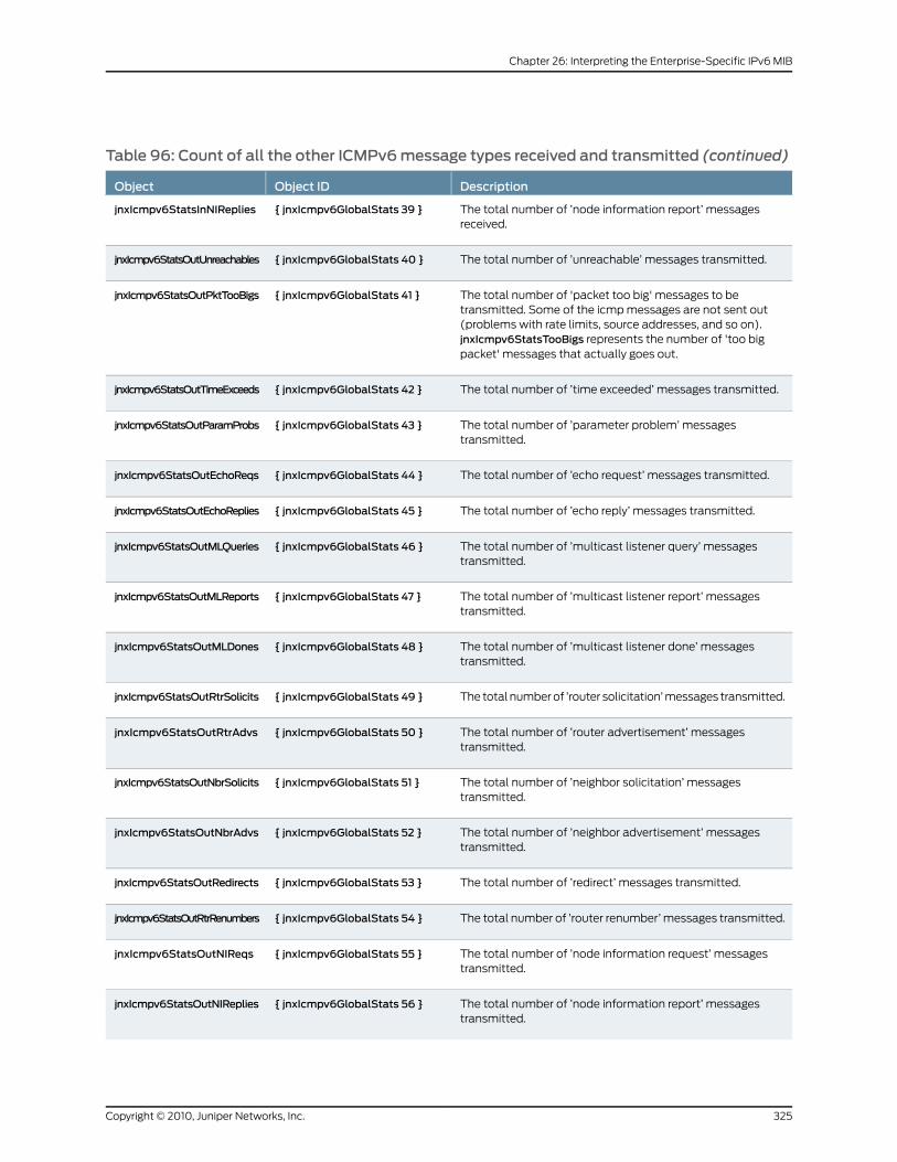
Table 96: Count of all the other ICMPv6message types received and transmitted (continued)
DescriptionObject IDObject
The total number of ’node information report’ messagesreceived.
{ jnxIcmpv6GlobalStats 39 }jnxIcmpv6StatsInNIReplies
The total number of ’unreachable’ messages transmitted.{ jnxIcmpv6GlobalStats 40 }jnxIcmpv6StatsOutUnreachables
The total number of 'packet too big' messages to betransmitted. Some of the icmp messages are not sent out(problems with rate limits, source addresses, and so on).jnxIcmpv6StatsTooBigs represents the number of 'too bigpacket' messages that actually goes out.
{ jnxIcmpv6GlobalStats 41 }jnxIcmpv6StatsOutPktTooBigs
The total number of ’time exceeded’ messages transmitted.{ jnxIcmpv6GlobalStats 42 }jnxIcmpv6StatsOutTimeExceeds
The total number of ’parameter problem’ messagestransmitted.
{ jnxIcmpv6GlobalStats 43 }jnxIcmpv6StatsOutParamProbs
The total number of ’echo request’ messages transmitted.{ jnxIcmpv6GlobalStats 44 }jnxIcmpv6StatsOutEchoReqs
The total number of ’echo reply’ messages transmitted.{ jnxIcmpv6GlobalStats 45 }jnxIcmpv6StatsOutEchoReplies
The total number of ’multicast listener query’ messagestransmitted.
{ jnxIcmpv6GlobalStats 46 }jnxIcmpv6StatsOutMLQueries
The total number of ’multicast listener report’ messagestransmitted.
{ jnxIcmpv6GlobalStats 47 }jnxIcmpv6StatsOutMLReports
The total number of ’multicast listener done’ messagestransmitted.
{ jnxIcmpv6GlobalStats 48 }jnxIcmpv6StatsOutMLDones
The total number of ’router solicitation’ messages transmitted.{ jnxIcmpv6GlobalStats 49 }jnxIcmpv6StatsOutRtrSolicits
The total number of ’router advertisement’ messagestransmitted.
{ jnxIcmpv6GlobalStats 50 }jnxIcmpv6StatsOutRtrAdvs
The total number of ’neighbor solicitation’ messagestransmitted.
{ jnxIcmpv6GlobalStats 51 }jnxIcmpv6StatsOutNbrSolicits
The total number of ’neighbor advertisement’ messagestransmitted.
{ jnxIcmpv6GlobalStats 52 }jnxIcmpv6StatsOutNbrAdvs
The total number of ’redirect’ messages transmitted.{ jnxIcmpv6GlobalStats 53 }jnxIcmpv6StatsOutRedirects
The total number of ’router renumber’ messages transmitted.{ jnxIcmpv6GlobalStats 54 }jnxIcmpv6StatsOutRtrRenumbers
The total number of ’node information request’ messagestransmitted.
{ jnxIcmpv6GlobalStats 55 }jnxIcmpv6StatsOutNIReqs
The total number of ’node information report’ messagestransmitted.
{ jnxIcmpv6GlobalStats 56 }jnxIcmpv6StatsOutNIReplies
325Copyright © 2010, Juniper Networks, Inc.
Chapter 26: Interpreting the Enterprise-Specific IPv6 MIB

RelatedDocumentation
• IPv6 MIB Overview on page 319
• jnxIpv6GlobalStats on page 319
Copyright © 2010, Juniper Networks, Inc.326
SRX100, SRX210, SRX220, SRX240, and SRX650 Services Gateways MIB Reference
CHAPTER 27
Interpreting the Enterprise-SpecificNetwork Address TranslationObjectsMIB
This chapter contains the following topics:
• Network Address Translation Objects MIB on page 327
• Source NAT Table on page 328
• New Source NAT Table on page 329
• jnxJsNatIfSrcPoolPortTable on page 331
• NAT Rule Hit Table on page 332
• NAT Pool Hit Table on page 332
• NAT Trap Definitions on page 333
Network Address Translation Objects MIB
The Juniper Networks enterprise-specific Network Address Translation (NAT) Objects
MIB, jnxJsNatMIB, whose object ID is {jnxJsNAT 1}, defines the objects that are used to
monitor NAT attributes.
Related NAT Objects MIB include:
• jnxJsNatNotifications {jnxJsNatMIB 0}
• jnxJsNatObjects {jnxJsNatMIB 1}
• jnxJsNatTrapVars {jnxJsNatMIB 2}
For a downloadable version of this MIB, see
http://www.juniper.net/techpubs/en_US/junos10.4/topics/reference/mibs/mib-jnx-js-nat.txt
.
For information about the enterprise-specific Network Address Translation MIB objects,
see the following topics:
• Source NAT Table on page 328
• New Source NAT Table on page 329
• jnxJsNatIfSrcPoolPortTable on page 331
327Copyright © 2010, Juniper Networks, Inc.
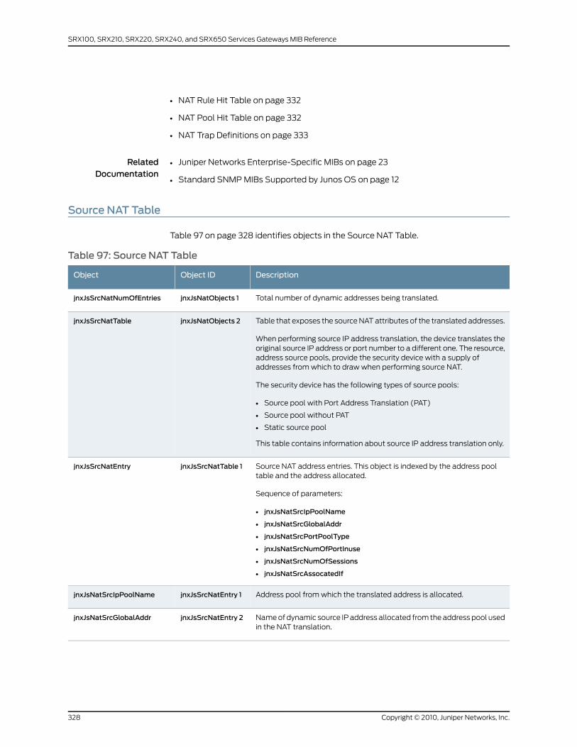
• NAT Rule Hit Table on page 332
• NAT Pool Hit Table on page 332
• NAT Trap Definitions on page 333
RelatedDocumentation
Juniper Networks Enterprise-Specific MIBs on page 23•
• Standard SNMP MIBs Supported by Junos OS on page 12
Source NAT Table
Table 97 on page 328 identifies objects in the Source NAT Table.
Table 97: Source NAT Table
DescriptionObject IDObject
Total number of dynamic addresses being translated.jnxJsNatObjects 1jnxJsSrcNatNumOfEntries
Table that exposes the source NAT attributes of the translated addresses.
When performing source IP address translation, the device translates theoriginal source IP address or port number to a different one. The resource,address source pools, provide the security device with a supply ofaddresses from which to draw when performing source NAT.
The security device has the following types of source pools:
• Source pool with Port Address Translation (PAT)
• Source pool without PAT
• Static source pool
This table contains information about source IP address translation only.
jnxJsNatObjects 2jnxJsSrcNatTable
Source NAT address entries. This object is indexed by the address pooltable and the address allocated.
Sequence of parameters:
• jnxJsNatSrcIpPoolName
• jnxJsNatSrcGlobalAddr
• jnxJsNatSrcPortPoolType
• jnxJsNatSrcNumOfPortInuse
• jnxJsNatSrcNumOfSessions
• jnxJsNatSrcAssocatedIf
jnxJsSrcNatTable 1jnxJsSrcNatEntry
Address pool from which the translated address is allocated.jnxJsSrcNatEntry 1jnxJsNatSrcIpPoolName
Name of dynamic source IP address allocated from the address pool usedin the NAT translation.
jnxJsSrcNatEntry 2jnxJsNatSrcGlobalAddr
Copyright © 2010, Juniper Networks, Inc.328
SRX100, SRX210, SRX220, SRX240, and SRX650 Services Gateways MIB Reference
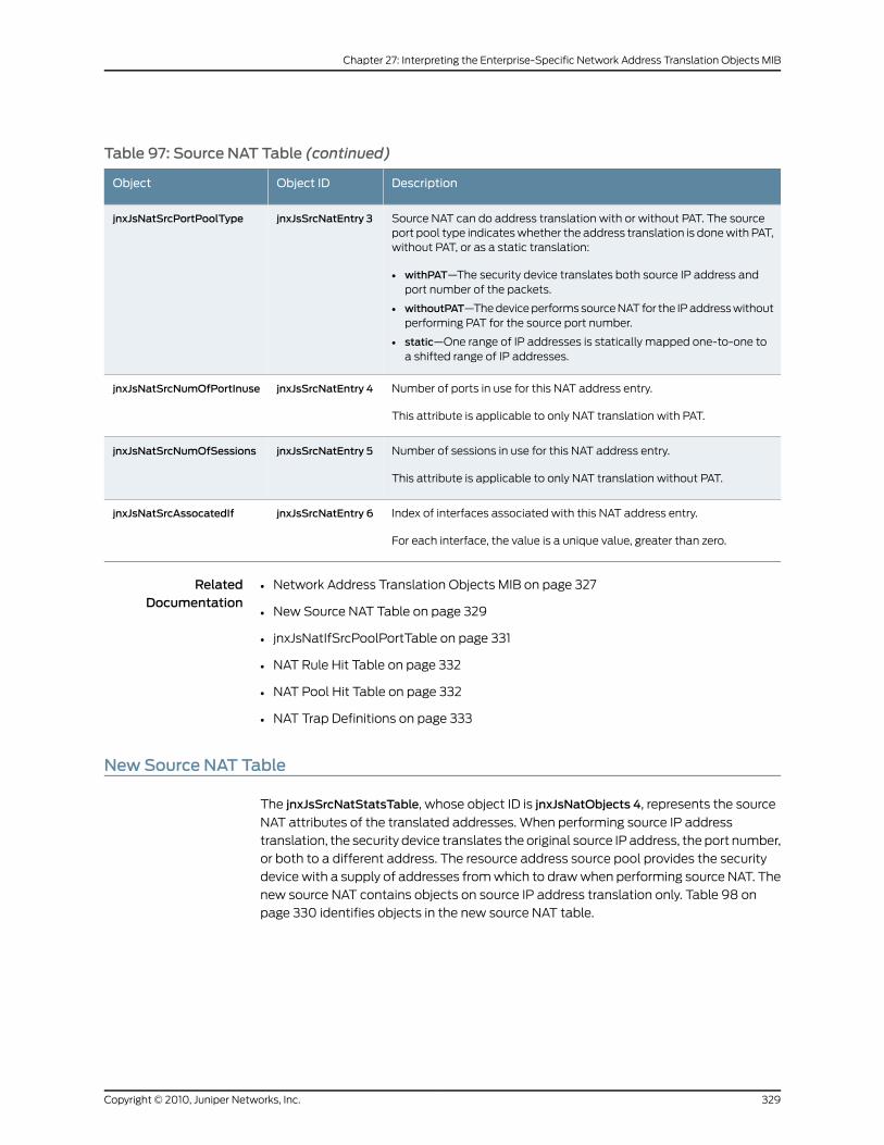
Table 97: Source NAT Table (continued)
DescriptionObject IDObject
Source NAT can do address translation with or without PAT. The sourceport pool type indicates whether the address translation is done with PAT,without PAT, or as a static translation:
• withPAT—The security device translates both source IP address andport number of the packets.
• withoutPAT—The device performs source NAT for the IP address withoutperforming PAT for the source port number.
• static—One range of IP addresses is statically mapped one-to-one toa shifted range of IP addresses.
jnxJsSrcNatEntry 3jnxJsNatSrcPortPoolType
Number of ports in use for this NAT address entry.
This attribute is applicable to only NAT translation with PAT.
jnxJsSrcNatEntry 4jnxJsNatSrcNumOfPortInuse
Number of sessions in use for this NAT address entry.
This attribute is applicable to only NAT translation without PAT.
jnxJsSrcNatEntry 5jnxJsNatSrcNumOfSessions
Index of interfaces associated with this NAT address entry.
For each interface, the value is a unique value, greater than zero.
jnxJsSrcNatEntry 6jnxJsNatSrcAssocatedIf
RelatedDocumentation
Network Address Translation Objects MIB on page 327•
• New Source NAT Table on page 329
• jnxJsNatIfSrcPoolPortTable on page 331
• NAT Rule Hit Table on page 332
• NAT Pool Hit Table on page 332
• NAT Trap Definitions on page 333
NewSource NAT Table
The jnxJsSrcNatStatsTable, whose object ID is jnxJsNatObjects 4, represents the source
NAT attributes of the translated addresses. When performing source IP address
translation, the security device translates the original source IP address, the port number,
or both to a different address. The resource address source pool provides the security
device with a supply of addresses from which to draw when performing source NAT. The
new source NAT contains objects on source IP address translation only. Table 98 on
page 330 identifies objects in the new source NAT table.
329Copyright © 2010, Juniper Networks, Inc.
Chapter 27: Interpreting the Enterprise-Specific Network Address Translation Objects MIB
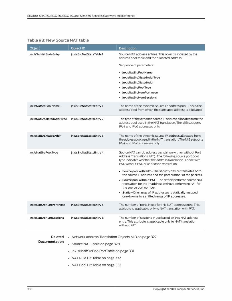
Table 98: New Source NAT table
DescriptionObject IDObject
Source NAT address entries. This object is indexed by theaddress pool table and the allocated address.
Sequence of parameters:
• jnxJsNatSrcPoolName
• jnxJsNatSrcXlatedAddrType
• jnxJsNatSrcXlatedAddr
• jnxJsNatSrcPoolType
• jnxJsNatSrcNumPortInuse
• jnxJsNatSrcNumSessions
jnxJsSrcNatStatsTable 1jnxJsSrcNatStatsEntry
The name of the dynamic source IP address pool. This is theaddress pool from which the translated address is allocated.
jnxJsSrcNatStatsEntry 1jnxJsNatSrcPoolName
The type of the dynamic source IP address allocated from theaddress pool used in the NAT translation. The MIB supportsIPv4 and IPv6 addresses only.
jnxJsSrcNatStatsEntry 2jnxJsNatSrcXlatedAddrType
The name of the dynamic source IP address allocated fromthe address pool used in the NAT translation. The MIB supportsIPv4 and IPv6 addresses only.
jnxJsSrcNatStatsEntry 3jnxJsNatSrcXlatedAddr
Source NAT can do address translation with or without PortAddress Translation (PAT). The following source port pooltype indicates whether the address translation is done withPAT, without PAT, or as a static translation:
• Source pool with PAT—The security device translates boththe source IP address and the port number of the packets.
• Source pool without PAT—The device performs source NATtranslation for the IP address without performing PAT forthe source port number.
• Static—One range of IP addresses is statically mappedone-to-one to a shifted range of IP addresses.
jnxJsSrcNatStatsEntry 4jnxJsNatSrcPoolType
The number of ports in use for this NAT address entry. Thisattribute is applicable only to NAT translation with PAT.
jnxJsSrcNatStatsEntry 5jnxJsNatSrcNumPortInuse
The number of sessions in use based on this NAT addressentry. This attribute is applicable only to NAT translationwithout PAT.
jnxJsSrcNatStatsEntry 6jnxJsNatSrcNumSessions
RelatedDocumentation
Network Address Translation Objects MIB on page 327•
• Source NAT Table on page 328
• jnxJsNatIfSrcPoolPortTable on page 331
• NAT Rule Hit Table on page 332
• NAT Pool Hit Table on page 332
Copyright © 2010, Juniper Networks, Inc.330
SRX100, SRX210, SRX220, SRX240, and SRX650 Services Gateways MIB Reference
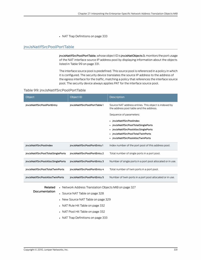
• NAT Trap Definitions on page 333
jnxJsNatIfSrcPoolPortTable
jnxJsNatIfSrcPoolPortTable, whose object ID is jnxJsNatObjects3, monitors the port usage
of the NAT interface source IP address pool by displaying information about the objects
listed in Table 99 on page 331.
The interface source pool is predefined. This source pool is referenced in a policy in which
it is configured. The security device translates the source IP address to the address of
the egress interface for the traffic, matching a policy that references the interface source
pool. The security device always applies PAT for the interface source pool.
Table 99: jnxJsNatIfSrcPoolPortTable
DescriptionObject IDObject
Source NAT address entries. This object is indexed bythe address pool table and the address.
Sequence of parameters:
• jnxJsNatIfSrcPoolIndex
• jnxJsNatIfSrcPoolTotalSinglePorts
• jnxJsNatIfSrcPoolAllocSinglePorts
• jnxJsNatIfSrcPoolTotalTwinPorts
• jnxJsNatIfSrcPoolAllocTwinPorts
jnxJsNatIfSrcPoolPortTable 1jnxJsNatIfSrcPoolPortEntry
Index number of the port pool of this address pool.jnxJsNatIfSrcPoolPortEntry 1jnxJsNatIfSrcPoolIndex
Total number of single ports in a port pool.jnxJsNatIfSrcPoolPortEntry 2jnxJsNatIfSrcPoolTotalSinglePorts
Number of single ports in a port pool allocated or in use.jnxJsNatIfSrcPoolPortEntry 3jnxJsNatIfSrcPoolAllocSinglePorts
Total number of twin ports in a port pool.jnxJsNatIfSrcPoolPortEntry 4jnxJsNatIfSrcPoolTotalTwinPorts
Number of twin ports in a port pool allocated or in use.jnxJsNatIfSrcPoolPortEntry 5jnxJsNatIfSrcPoolAllocTwinPorts
RelatedDocumentation
Network Address Translation Objects MIB on page 327•
• Source NAT Table on page 328
• New Source NAT Table on page 329
• NAT Rule Hit Table on page 332
• NAT Pool Hit Table on page 332
• NAT Trap Definitions on page 333
331Copyright © 2010, Juniper Networks, Inc.
Chapter 27: Interpreting the Enterprise-Specific Network Address Translation Objects MIB
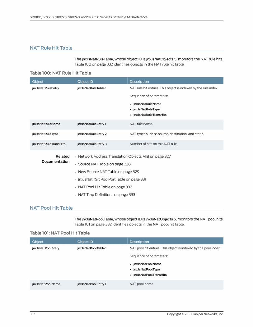
NAT Rule Hit Table
The jnxJsNatRuleTable, whose object ID is jnxJsNatObjects 5, monitors the NAT rule hits.
Table 100 on page 332 identifies objects in the NAT rule hit table.
Table 100: NAT Rule Hit Table
DescriptionObject IDObject
NAT rule hit entries. This object is indexed by the rule index.
Sequence of parameters:
• jnxJsNatRuleName
• jnxJsNatRuleType
• jnxJsNatRuleTransHits
jnxJsNatRuleTable 1jnxJsNatRuleEntry
NAT rule name.jnxJsNatRuleEntry 1jnxJsNatRuleName
NAT types such as source, destination, and static.jnxJsNatRuleEntry 2jnxJsNatRuleType
Number of hits on this NAT rule.jnxJsNatRuleEntry 3jnxJsNatRuleTransHits
RelatedDocumentation
Network Address Translation Objects MIB on page 327•
• Source NAT Table on page 328
• New Source NAT Table on page 329
• jnxJsNatIfSrcPoolPortTable on page 331
• NAT Pool Hit Table on page 332
• NAT Trap Definitions on page 333
NAT Pool Hit Table
The jnxJsNatPoolTable, whose object ID is jnxJsNatObjects 6, monitors the NAT pool hits.
Table 101 on page 332 identifies objects in the NAT pool hit table.
Table 101: NAT Pool Hit Table
DescriptionObject IDObject
NAT pool hit entries. This object is indexed by the pool index.
Sequence of parameters:
• jnxJsNatPoolName
• jnxJsNatPoolType
• jnxJsNatPoolTransHits
jnxJsNatPoolTable 1jnxJsNatPoolEntry
NAT pool name.jnxJsNatPoolEntry 1jnxJsNatPoolName
Copyright © 2010, Juniper Networks, Inc.332
SRX100, SRX210, SRX220, SRX240, and SRX650 Services Gateways MIB Reference

Table 101: NAT Pool Hit Table (continued)
DescriptionObject IDObject
NAT types such as source, destination, and static.jnxJsNatPoolEntry 2jnxJsNatPoolType
Number of hits on this NAT pool.jnxJsNatPoolEntry 3jnxJsNatPoolTransHits
RelatedDocumentation
Network Address Translation Objects MIB on page 327•
• Source NAT Table on page 328
• New Source NAT Table on page 329
• jnxJsNatIfSrcPoolPortTable on page 331
• NAT Rule Hit Table on page 332
• NAT Trap Definitions on page 333
NAT Trap Definitions
Table 102 on page 333 lists NAT trap definition objects.
Table 102: NAT Trap Definitions
DescriptionObject IDObject
NAT address pool untilization threshold status trap to signify thatthe address pool utilization either exceeds a certain percentageor is clear of that percentage.
jnxJsNatSrcIpPoolName is the name of the resource pool.
jnxJsNatAddrPoolUtil is the percentage of utilization of the addresspool.
jnxJsNatNotifications1
jnxJsNatAddrPoolThresholdStatus
Dynamic address pool utilization expressed as a percentage.jnxJsNatTrapVars 1jnxJsNatAddrPoolUtil
RelatedDocumentation
• Network Address Translation Objects MIB on page 327
• Source NAT Table on page 328
• New Source NAT Table on page 329
• jnxJsNatIfSrcPoolPortTable on page 331
• NAT Rule Hit Table on page 332
• NAT Pool Hit Table on page 332
333Copyright © 2010, Juniper Networks, Inc.
Chapter 27: Interpreting the Enterprise-Specific Network Address Translation Objects MIB

Copyright © 2010, Juniper Networks, Inc.334
SRX100, SRX210, SRX220, SRX240, and SRX650 Services Gateways MIB Reference
CHAPTER 28
Interpreting theEnterprise-SpecificPacketForwarding Engine MIB
• Packet Forwarding Engine MIB on page 335
• jnxPfeNotifyGlTable on page 335
• jnxPfeNotifyTypeTable on page 337
Packet Forwarding EngineMIB
The Juniper Networks enterprise-specific Packet Forwarding Engine MIB, whose object
identifier is {jnxPfeMibRoot 1}, provides notification statistics for Packet Forwarding
Engines. For a downloadable version of this MIB, see
http://www.juniper.net/techpubs/en_US/junos10.4/topics/reference/mibs/mib-jnx-pfe.txt
.
NOTE: InformationprovidedbythisMIB ismodeledafter informationprovidedby theshowpfestatisticsnotificationcommand-line interface(CLI)command.
For information about the enterprise-specific Packet Forwarding Engine MIB objects, see
the following topics:
• jnxPfeNotifyGlTable on page 335
• jnxPfeNotifyTypeTable on page 337
RelatedDocumentation
Juniper Networks Enterprise-Specific MIBs on page 23•
• Standard SNMP MIBs Supported by Junos OS on page 12
jnxPfeNotifyGlTable
jnxPfeNotifyGlTable contains global Packet Forwarding Engine notification statistics.
JnxPfeNotifyGlEntry contains notification statistics for each Packet Forwarding Engine
slot. Each entry has objects listed in Table 103 on page 336.
335Copyright © 2010, Juniper Networks, Inc.

Table 103: jnxPfeNotifyGlEntry
DescriptionObject IdentifierObject
The slot number for a set of Packet Forwarding Engine notificationstatistics.
jnxPfeNotifyGIEntry 1jnxPfeNotifyGISlot
The number of notifications reported by the Packet Forwarding Enginecontroller, which manages packet forwarding functions.
jnxPfeNotifyGIEntry 2jnxPfeNotifyGIParsed
The number of notifications dropped because they have expired.jnxPfeNotifyGIEntry 3jnxPfeNotifyGIAged
The number of notifications dropped because the notification resultformat is invalid. This counter is valid for Internet Processor-I and InternetProcessor-II only.
jnxPfeNotifyGIEntry 4jnxPfeNotifyGICorrupt
The number of notifications dropped because the notification has anillegal notification type.
jnxPfeNotifyGIEntry 5jnxPfeNotifyGIIllegal
The number of sample notifications reported by the Packet ForwardingEngine controller.
jnxPfeNotifyGIEntry 6jnxPfeNotifyGISample
The number of notifications dropped because the notification is largerthan the supported direct memory access (DMA) size.
jnxPfeNotifyGIEntry 7jnxPfeNotifyGIGiants
The number of options/TTL-expired notifications sent to serviceinterfaces as transit packets. This counter is valid for Internet Processor-Iand Internet Processor-II only.
jnxPfeNotifyGIEntry 8jnxPfeNotifyGITtlExceeded
The number of options/TTL-expired notifications that could not be sentto service interfaces as transit packets because the output interfacecould not be determined. This counter is valid for Internet Processor-Iand Internet Processor-II only.
jnxPfeNotifyGIEntry 9jnxPfeNotifyGITtlExcErrors
The number of IP options packets sent to a Services PIC.jnxPfeNotifyGIEntry 10jnxPfeNotifyGISvcOptAsp
The number of IP options packets sent to the Routing Engine.jnxPfeNotifyGIEntry 11jnxPfeNotifyGISvcOptRe
The number of notifications re-injected by a Services PIC after processingthe associated packets. The Packet Forwarding Engine will forward thesenotifications to their actual destination. This counter is valid for InternetProcessor-I and Internet Processor-II only.
jnxPfeNotifyGIEntry 12jnxPfeNotifyGIPostSvcOptOut
The number of TTL-expired transit packets.jnxPfeNotifyGIEntry 13jnxPfeNotifyGIOptTtlExp
The number of sample notifications dropped because the notificationsrefer to discarded packets in the Packet Forwarding Engine.
jnxPfeNotifyGIEntry 14jnxPfeNotifyGIDiscSample
The number of notification ignored because of Packet Forwarding Enginesoftware throttling (delaying or refusing requests).
jnxPfeNotifyGIEntry 15jnxPfeNotifyGIRateLimited
The number of notifications ignored because DMA memory could not beallocated.
jnxPfeNotifyGIEntry 16jnxPfeNotifyGIPktGetFails
Copyright © 2010, Juniper Networks, Inc.336
SRX100, SRX210, SRX220, SRX240, and SRX650 Services Gateways MIB Reference
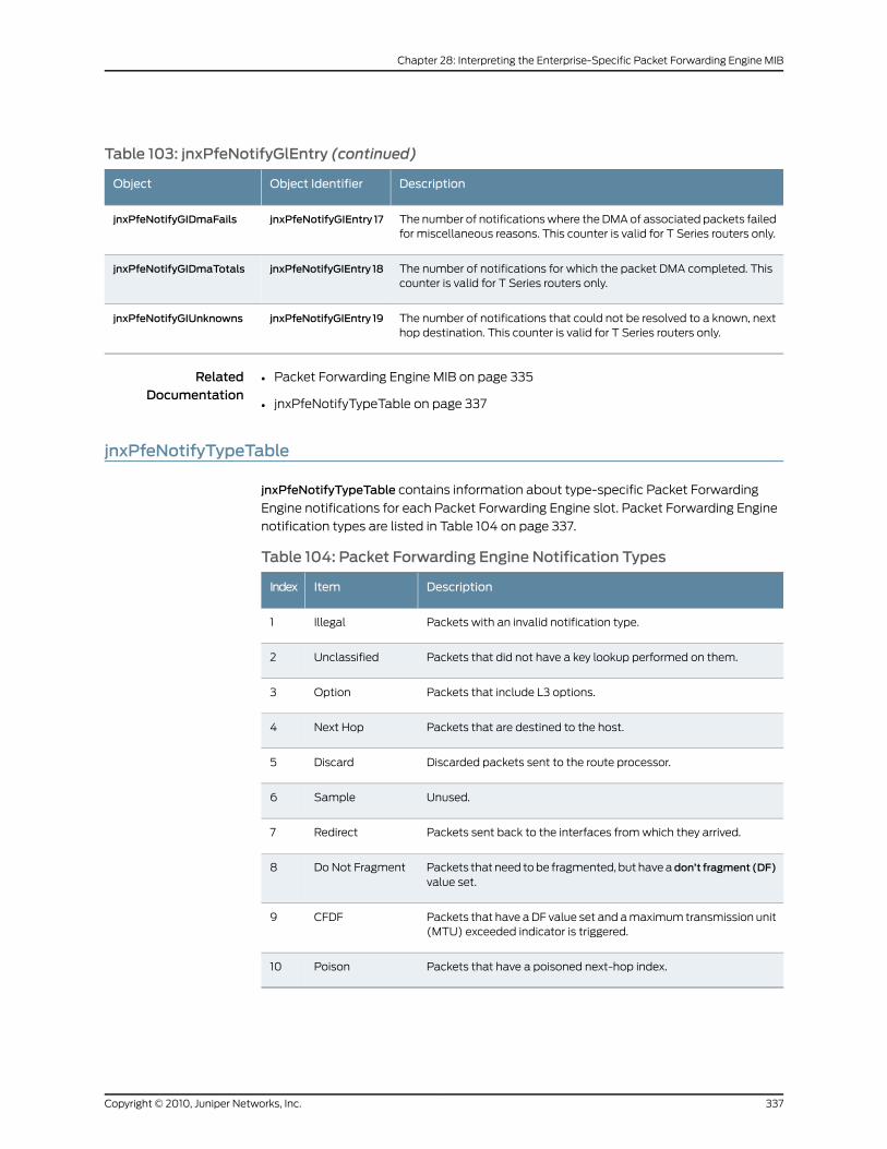
Table 103: jnxPfeNotifyGlEntry (continued)
DescriptionObject IdentifierObject
The number of notifications where the DMA of associated packets failedfor miscellaneous reasons. This counter is valid for T Series routers only.
jnxPfeNotifyGIEntry 17jnxPfeNotifyGIDmaFails
The number of notifications for which the packet DMA completed. Thiscounter is valid for T Series routers only.
jnxPfeNotifyGIEntry 18jnxPfeNotifyGIDmaTotals
The number of notifications that could not be resolved to a known, nexthop destination. This counter is valid for T Series routers only.
jnxPfeNotifyGIEntry 19jnxPfeNotifyGIUnknowns
RelatedDocumentation
Packet Forwarding Engine MIB on page 335•
• jnxPfeNotifyTypeTable on page 337
jnxPfeNotifyTypeTable
jnxPfeNotifyTypeTable contains information about type-specific Packet Forwarding
Engine notifications for each Packet Forwarding Engine slot. Packet Forwarding Engine
notification types are listed in Table 104 on page 337.
Table 104: Packet Forwarding Engine Notification Types
DescriptionItemIndex
Packets with an invalid notification type.Illegal1
Packets that did not have a key lookup performed on them.Unclassified2
Packets that include L3 options.Option3
Packets that are destined to the host.Next Hop4
Discarded packets sent to the route processor.Discard5
Unused.Sample6
Packets sent back to the interfaces from which they arrived.Redirect7
Packets that need to be fragmented, but have adon’t fragment (DF)value set.
Do Not Fragment8
Packets that have a DF value set and a maximum transmission unit(MTU) exceeded indicator is triggered.
CFDF9
Packets that have a poisoned next-hop index.Poison10
337Copyright © 2010, Juniper Networks, Inc.
Chapter 28: Interpreting the Enterprise-Specific Packet Forwarding Engine MIB
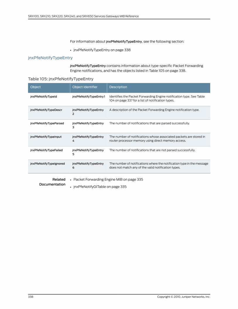
For information about jnxPfeNotifyTypeEntry, see the following section:
• jnxPfeNotifyTypeEntry on page 338
jnxPfeNotifyTypeEntry
jnxPfeNotifyTypeEntry contains information about type-specific Packet Forwarding
Engine notifications, and has the objects listed in Table 105 on page 338.
Table 105: jnxPfeNotifyTypeEntry
DescriptionObject IdentifierObject
Identifies the Packet Forwarding Engine notification type. See Table104 on page 337 for a list of notification types.
jnxPfeNotifyTypeEntry 1jnxPfeNotifyTypeId
A description of the Packet Forwarding Engine notification type.jnxPfeNotifyTypeEntry2
jnxPfeNotifyTypeDescr
The number of notifications that are parsed successfully.jnxPfeNotifyTypeEntry3
jnxPfeNotifyTypeParsed
The number of notifications whose associated packets are stored inrouter processor memory using direct memory access.
jnxPfeNotifyTypeEntry4
jnxPfeNotifyTypeInput
The number of notifications that are not parsed successfully.jnxPfeNotifyTypeEntry5
jnxPfeNotifyTypeFailed
The number of notifications where the notification type in the messagedoes not match any of the valid notification types.
jnxPfeNotifyTypeEntry6
jnxPfeNotifyTypeIgnored
RelatedDocumentation
• Packet Forwarding Engine MIB on page 335
• jnxPfeNotifyGlTable on page 335
Copyright © 2010, Juniper Networks, Inc.338
SRX100, SRX210, SRX220, SRX240, and SRX650 Services Gateways MIB Reference
CHAPTER 29
Interpreting the Enterprise-SpecificPing MIB
• PING MIB on page 339
• jnxPingCtlTable on page 340
• jnxPingResultsTable on page 344
• jnxPingProbeHistoryTable on page 348
• jnxPingLastTestResultTable on page 350
PINGMIB
The Juniper Networks enterprise-specific Ping MIB extends the standard Ping MIB control
table (RFC 2925). The Ping MIB, whose object identifier is {jnxMIbs 7}, allows you to
monitor network delay (latency), packet loss, network delay variation (jitter), one-way
latency, and other network statistics.
Items in this MIB are created when entries are created in the pingCtlTable of the Ping
MIB. Each item is indexed exactly as in the Ping MIB.
To view a complete copy of the enterprise-specific extensions to the Ping MIB, see
http://www.juniper.net/techpubs/en_US/junos10.4/topics/reference/mibs/mib-jnx-ping.txt
.
For information about using the Ping MIB and enterprise-specific Ping MIB, see the Junos
OS Network Management Configuration Guide.
For information about the enterprise-specific PING MIB objects, see the following topics:
• jnxPingCtlTable on page 340
• jnxPingResultsTable on page 344
• jnxPingProbeHistoryTable on page 348
• jnxPingLastTestResultTable on page 350
RelatedDocumentation
Juniper Networks Enterprise-Specific MIBs on page 23•
• Standard SNMP MIBs Supported by Junos OS on page 12
339Copyright © 2010, Juniper Networks, Inc.

jnxPingCtlTable
The enterprise-specific Ping MIB structure includes one main object, jnxPingCtlTable,
whose object identifier is jnxPingObjects 2, and defines the jnxPing control table for
providing enterprise-specific options to the corresponding pingCtlEntry. jnxpingCtTable
monitors thresholds; for example, the maximum allowed jitter in the trip time during a
text.
For information about objects in jnxPingCtlEntry, see:
• jnxPingCtlEntry on page 340
jnxPingCtlEntry
Each jnxPingCtlEntryhas two indexes identical to those of the correspondingpingCtlEntry.
Entries created in pingCtlTable are mirrored here. jnxPingCtlEntry objects are listed in the
Table 106 on page 340.
Table 106: jnxPingCtlEntry
DescriptionObject IdentifierObject
The first index. It is identical to thepingCtlOwnerIndex of the correspondingpingCtlEntry in the pingCtlTable.
jnxPingCtlEntry 1jnxCtlOwnerIndex
The other index and is identical to thepingCtlTestName of the correspondingpingCtlEntry in the pingCtlTable.
jnxPingCtlEntry 2jnxPingCtlTestName
Specifies the name of the outgoing interfacefor ping probes. This is the name-basedcomplement topingCtlIfIndex. A zero-lengthstring value for this object means that thisoption is not enabled. The following valuescan be set simultaneously, but only onevalue is used. The precedence order is asfollows:
• pingCtlIfIndex (see pingCtlTable in thePing MIB)
• jnxPingCtlIfName
• jnxPingCtlRoutingInstanceName
jnxPingCtlEntry 3jnxPingCtlIfName
Specifies the name of the routing instanceused when directing outgoing ping packets.The instance name specified must beconfigured at the [edit routing-instances]hierarchy level of the Junos configuration.The instance-type must be vrf.
jnxPingCtlEntry 6jnxPingCtlRoutingInstanceName
The maximum round-trip time allowed. Ifthis threshold is crossed by any probe, ajnxPingRttThresholdExceeded trap is sent.
jnxPingCtlEntry 7jnxPingCtlRttThreshold
Copyright © 2010, Juniper Networks, Inc.340
SRX100, SRX210, SRX220, SRX240, and SRX650 Services Gateways MIB Reference
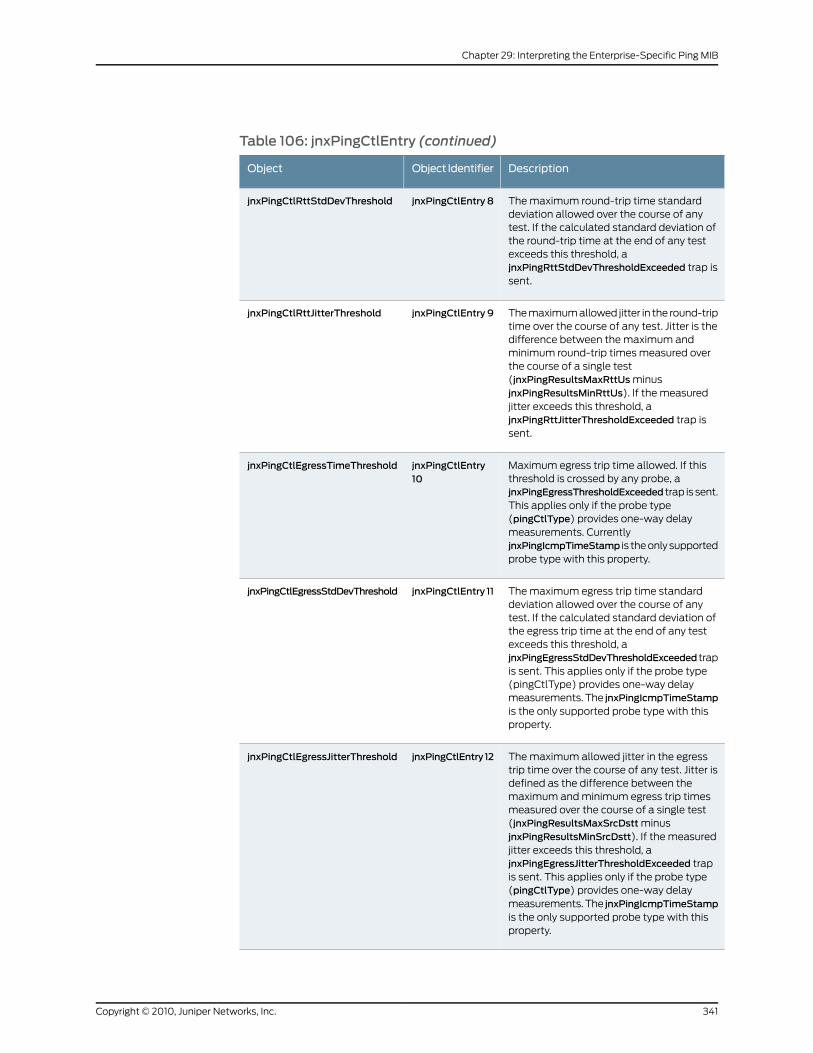
Table 106: jnxPingCtlEntry (continued)
DescriptionObject IdentifierObject
The maximum round-trip time standarddeviation allowed over the course of anytest. If the calculated standard deviation ofthe round-trip time at the end of any testexceeds this threshold, ajnxPingRttStdDevThresholdExceeded trap issent.
jnxPingCtlEntry 8jnxPingCtlRttStdDevThreshold
The maximum allowed jitter in the round-triptime over the course of any test. Jitter is thedifference between the maximum andminimum round-trip times measured overthe course of a single test(jnxPingResultsMaxRttUs minusjnxPingResultsMinRttUs). If the measuredjitter exceeds this threshold, ajnxPingRttJitterThresholdExceeded trap issent.
jnxPingCtlEntry 9jnxPingCtlRttJitterThreshold
Maximum egress trip time allowed. If thisthreshold is crossed by any probe, ajnxPingEgressThresholdExceeded trap is sent.This applies only if the probe type(pingCtlType) provides one-way delaymeasurements. CurrentlyjnxPingIcmpTimeStamp is the only supportedprobe type with this property.
jnxPingCtlEntry10
jnxPingCtlEgressTimeThreshold
The maximum egress trip time standarddeviation allowed over the course of anytest. If the calculated standard deviation ofthe egress trip time at the end of any testexceeds this threshold, ajnxPingEgressStdDevThresholdExceeded trapis sent. This applies only if the probe type(pingCtlType) provides one-way delaymeasurements. The jnxPingIcmpTimeStampis the only supported probe type with thisproperty.
jnxPingCtlEntry 11jnxPingCtlEgressStdDevThreshold
The maximum allowed jitter in the egresstrip time over the course of any test. Jitter isdefined as the difference between themaximum and minimum egress trip timesmeasured over the course of a single test(jnxPingResultsMaxSrcDstt minusjnxPingResultsMinSrcDstt). If the measuredjitter exceeds this threshold, ajnxPingEgressJitterThresholdExceeded trapis sent. This applies only if the probe type(pingCtlType) provides one-way delaymeasurements. The jnxPingIcmpTimeStampis the only supported probe type with thisproperty.
jnxPingCtlEntry 12jnxPingCtlEgressJitterThreshold
341Copyright © 2010, Juniper Networks, Inc.
Chapter 29: Interpreting the Enterprise-Specific Ping MIB
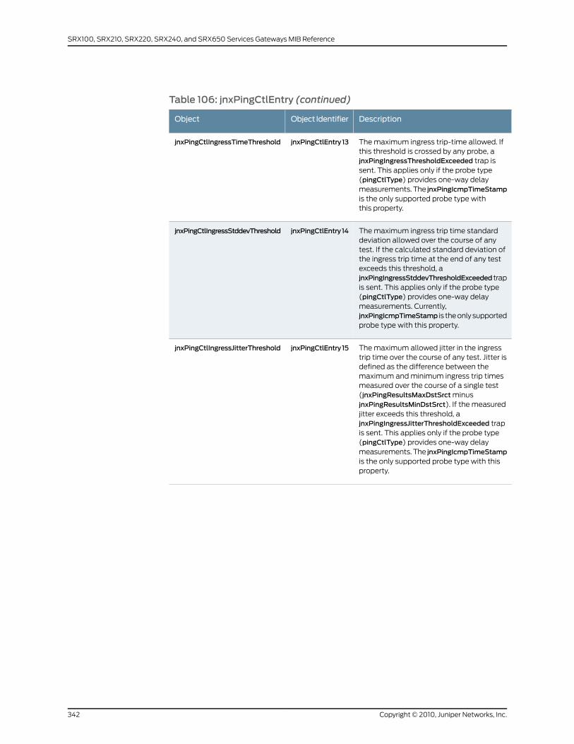
Table 106: jnxPingCtlEntry (continued)
DescriptionObject IdentifierObject
The maximum ingress trip-time allowed. Ifthis threshold is crossed by any probe, ajnxPingIngressThresholdExceeded trap issent. This applies only if the probe type(pingCtlType) provides one-way delaymeasurements. The jnxPingIcmpTimeStampis the only supported probe type withthis property.
jnxPingCtlEntry13jnxPingCtlIngressTimeThreshold
The maximum ingress trip time standarddeviation allowed over the course of anytest. If the calculated standard deviation ofthe ingress trip time at the end of any testexceeds this threshold, ajnxPingIngressStddevThresholdExceeded trapis sent. This applies only if the probe type(pingCtlType) provides one-way delaymeasurements. Currently,jnxPingIcmpTimeStamp is the only supportedprobe type with this property.
jnxPingCtlEntry14jnxPingCtlIngressStddevThreshold
The maximum allowed jitter in the ingresstrip time over the course of any test. Jitter isdefined as the difference between themaximum and minimum ingress trip timesmeasured over the course of a single test(jnxPingResultsMaxDstSrct minusjnxPingResultsMinDstSrct). If the measuredjitter exceeds this threshold, ajnxPingIngressJitterThresholdExceeded trapis sent. This applies only if the probe type(pingCtlType) provides one-way delaymeasurements. The jnxPingIcmpTimeStampis the only supported probe type with thisproperty.
jnxPingCtlEntry15jnxPingCtlIngressJitterThreshold
Copyright © 2010, Juniper Networks, Inc.342
SRX100, SRX210, SRX220, SRX240, and SRX650 Services Gateways MIB Reference
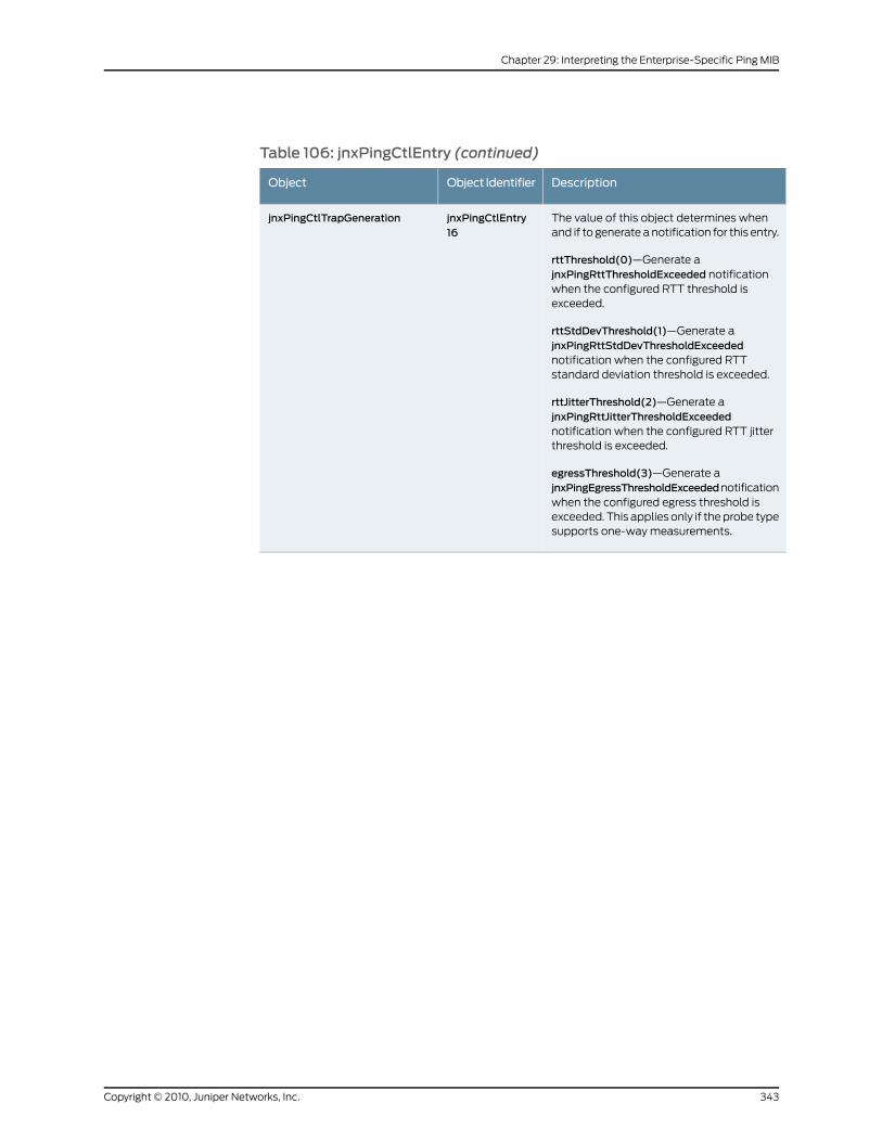
Table 106: jnxPingCtlEntry (continued)
DescriptionObject IdentifierObject
The value of this object determines whenand if to generate a notification for this entry.
rttThreshold(0)—Generate ajnxPingRttThresholdExceeded notificationwhen the configured RTT threshold isexceeded.
rttStdDevThreshold(1)—Generate ajnxPingRttStdDevThresholdExceedednotification when the configured RTTstandard deviation threshold is exceeded.
rttJitterThreshold(2)—Generate ajnxPingRttJitterThresholdExceedednotification when the configured RTT jitterthreshold is exceeded.
egressThreshold(3)—Generate ajnxPingEgressThresholdExceedednotificationwhen the configured egress threshold isexceeded. This applies only if the probe typesupports one-way measurements.
jnxPingCtlEntry16
jnxPingCtlTrapGeneration
343Copyright © 2010, Juniper Networks, Inc.
Chapter 29: Interpreting the Enterprise-Specific Ping MIB

Table 106: jnxPingCtlEntry (continued)
DescriptionObject IdentifierObject
egressStdDevThreshold(4)—Generate ajnxPingEgressStdDevThresholdExceedednotification when the configured egressstandard deviation threshold is exceeded.This applies only if the probe type supportsone-way measurements.
egressJitterThreshold(5)—Generate ajnxPingEgressJitterThresholdExceedednotification when the configured egress jitterthreshold is exceeded. This applies only ifthe probe type supports one-waymeasurements.
ingressThreshold(6)—Generate ajnxPingIngressThresholdExceedednotification when the configured ingressthreshold is exceeded. This applies only ifthe probe type supports one-waymeasurements.
ingressStdDevThreshold(7)—Generate ajnxPingIngressStdDevThresholdExceedednotification when the configured ingressstandard deviation threshold is exceeded.This applies only if the probe type supportsone way measurements.
ingressJitterThreshold(8)—Generate ajnxPingIngressJitterThresholdExceedednotification when the configured ingress jitterthreshold is exceeded. This applies only ifthe probe type supports one-waymeasurements. The value of this objectdefaults to zero, indicating that none of theabove options have been selected.
RelatedDocumentation
PING MIB on page 339•
• jnxPingResultsTable on page 344
• jnxPingProbeHistoryTable on page 348
• jnxPingLastTestResultTable on page 350
jnxPingResultsTable
jnxPingResultsTable, whose object identifier is jnxPingObjects 3, gathers ping test results
on traffic on round-trip, ingress, and egress trip delays. This is useful when you want to
measure the performance of your network and verify service-level agreements with your
vendors.
The jnxPingResultsEntry objects are listed in Table 107 on page 345.
Copyright © 2010, Juniper Networks, Inc.344
SRX100, SRX210, SRX220, SRX240, and SRX650 Services Gateways MIB Reference
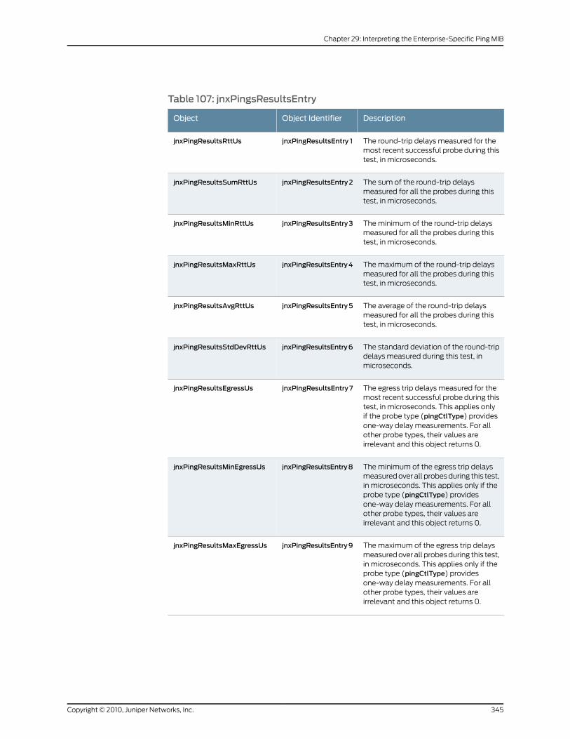
Table 107: jnxPingsResultsEntry
DescriptionObject IdentifierObject
The round-trip delays measured for themost recent successful probe during thistest, in microseconds.
jnxPingResultsEntry 1jnxPingResultsRttUs
The sum of the round-trip delaysmeasured for all the probes during thistest, in microseconds.
jnxPingResultsEntry2jnxPingResultsSumRttUs
The minimum of the round-trip delaysmeasured for all the probes during thistest, in microseconds.
jnxPingResultsEntry3jnxPingResultsMinRttUs
The maximum of the round-trip delaysmeasured for all the probes during thistest, in microseconds.
jnxPingResultsEntry4jnxPingResultsMaxRttUs
The average of the round-trip delaysmeasured for all the probes during thistest, in microseconds.
jnxPingResultsEntry5jnxPingResultsAvgRttUs
The standard deviation of the round-tripdelays measured during this test, inmicroseconds.
jnxPingResultsEntry6jnxPingResultsStdDevRttUs
The egress trip delays measured for themost recent successful probe during thistest, in microseconds. This applies onlyif the probe type (pingCtlType) providesone-way delay measurements. For allother probe types, their values areirrelevant and this object returns 0.
jnxPingResultsEntry7jnxPingResultsEgressUs
The minimum of the egress trip delaysmeasured over all probes during this test,in microseconds. This applies only if theprobe type (pingCtlType) providesone-way delay measurements. For allother probe types, their values areirrelevant and this object returns 0.
jnxPingResultsEntry8jnxPingResultsMinEgressUs
The maximum of the egress trip delaysmeasured over all probes during this test,in microseconds. This applies only if theprobe type (pingCtlType) providesone-way delay measurements. For allother probe types, their values areirrelevant and this object returns 0.
jnxPingResultsEntry9jnxPingResultsMaxEgressUs
345Copyright © 2010, Juniper Networks, Inc.
Chapter 29: Interpreting the Enterprise-Specific Ping MIB
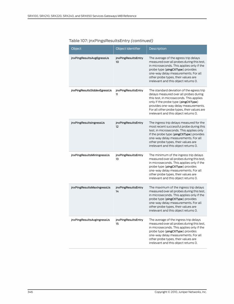
Table 107: jnxPingsResultsEntry (continued)
DescriptionObject IdentifierObject
The average of the egress trip delaysmeasured over all probes during this test,in microseconds. This applies only if theprobe type (pingCtlType) providesone-way delay measurements. For allother probe types, their values areirrelevant and this object returns 0.
jnxPingResultsEntry10
jnxPingResultsAvgEgressUs
The standard deviation of the egress tripdelays measured over all probes duringthis test, in microseconds. This appliesonly if the probe type (pingCtlType)provides one-way delay measurements.For all other probe types, their values areirrelevant and this object returns 0.
jnxPingResultsEntry11
jnxPingResultsStddevEgressUs
The ingress trip delays measured for themost recent successful probe during thistest, in microseconds. This applies onlyif the probe type (pingCtlType) providesone-way delay measurements. For allother probe types, their values areirrelevant and this object returns 0.
jnxPingResultsEntry12
jnxPingResultsIngressUs
The minimum of the ingress trip delaysmeasured over all probes during this test,in microseconds. This applies only if theprobe type (pingCtlType) providesone-way delay measurements. For allother probe types, their values areirrelevant and this object returns 0.
jnxPingResultsEntry13
jnxPingResultsMinIngressUs
The maximum of the ingress trip delaysmeasured over all probes during this test,in microseconds. This applies only if theprobe type (pingCtlType) providesone-way delay measurements. For allother probe types, their values areirrelevant and this object returns 0.
jnxPingResultsEntry14
jnxPingResultsMaxIngressUs
The average of the ingress trip delaysmeasured over all probes during this test,in microseconds. This applies only if theprobe type (pingCtlType) providesone-way delay measurements. For allother probe types, their values areirrelevant and this object returns 0.
jnxPingResultsEntry15
jnxPingResultsAvgIngressUs
Copyright © 2010, Juniper Networks, Inc.346
SRX100, SRX210, SRX220, SRX240, and SRX650 Services Gateways MIB Reference
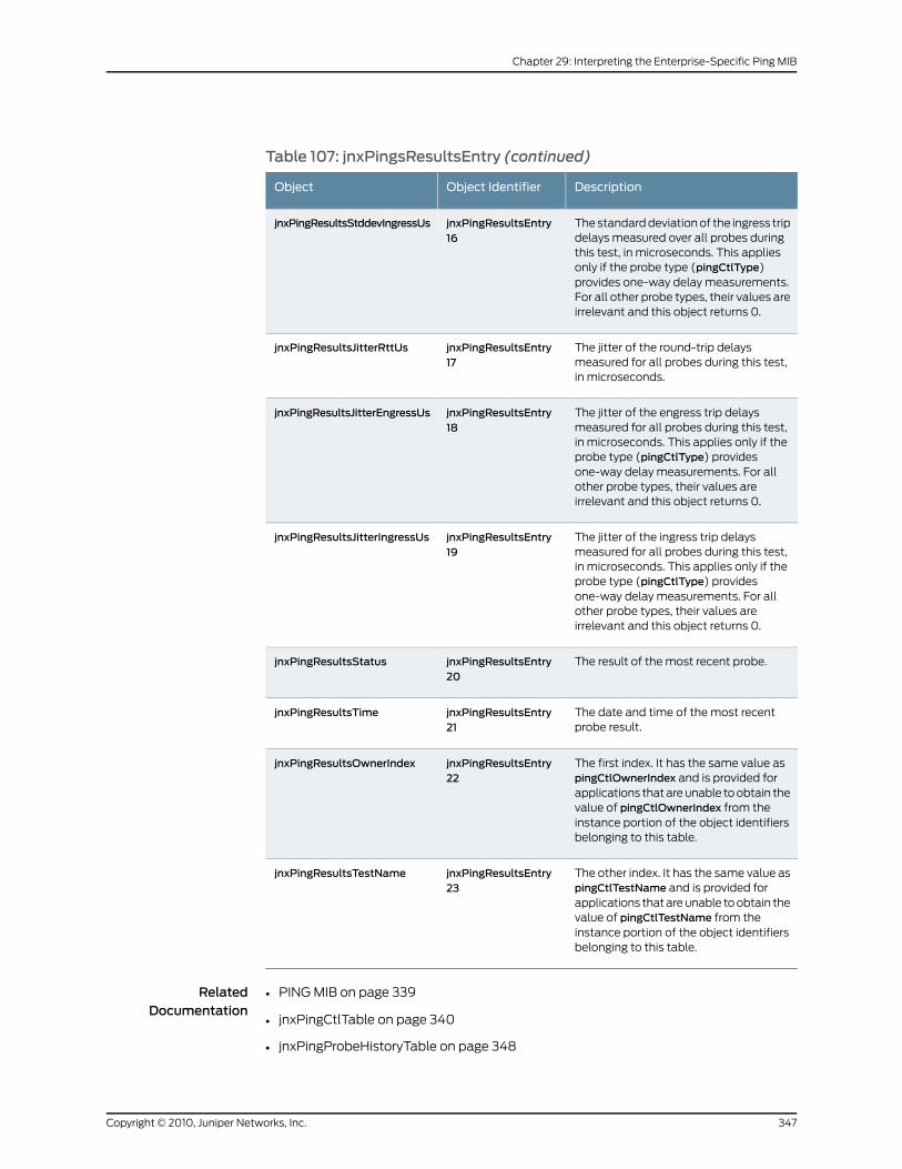
Table 107: jnxPingsResultsEntry (continued)
DescriptionObject IdentifierObject
The standard deviation of the ingress tripdelays measured over all probes duringthis test, in microseconds. This appliesonly if the probe type (pingCtlType)provides one-way delay measurements.For all other probe types, their values areirrelevant and this object returns 0.
jnxPingResultsEntry16
jnxPingResultsStddevIngressUs
The jitter of the round-trip delaysmeasured for all probes during this test,in microseconds.
jnxPingResultsEntry17
jnxPingResultsJitterRttUs
The jitter of the engress trip delaysmeasured for all probes during this test,in microseconds. This applies only if theprobe type (pingCtlType) providesone-way delay measurements. For allother probe types, their values areirrelevant and this object returns 0.
jnxPingResultsEntry18
jnxPingResultsJitterEngressUs
The jitter of the ingress trip delaysmeasured for all probes during this test,in microseconds. This applies only if theprobe type (pingCtlType) providesone-way delay measurements. For allother probe types, their values areirrelevant and this object returns 0.
jnxPingResultsEntry19
jnxPingResultsJitterIngressUs
The result of the most recent probe.jnxPingResultsEntry20
jnxPingResultsStatus
The date and time of the most recentprobe result.
jnxPingResultsEntry21
jnxPingResultsTime
The first index. It has the same value aspingCtlOwnerIndex and is provided forapplications that are unable to obtain thevalue of pingCtlOwnerIndex from theinstance portion of the object identifiersbelonging to this table.
jnxPingResultsEntry22
jnxPingResultsOwnerIndex
The other index. It has the same value aspingCtlTestName and is provided forapplications that are unable to obtain thevalue of pingCtlTestName from theinstance portion of the object identifiersbelonging to this table.
jnxPingResultsEntry23
jnxPingResultsTestName
RelatedDocumentation
PING MIB on page 339•
• jnxPingCtlTable on page 340
• jnxPingProbeHistoryTable on page 348
347Copyright © 2010, Juniper Networks, Inc.
Chapter 29: Interpreting the Enterprise-Specific Ping MIB
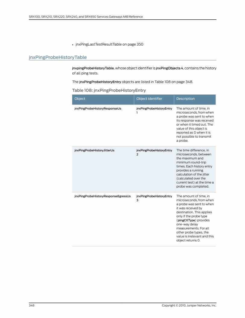
• jnxPingLastTestResultTable on page 350
jnxPingProbeHistoryTable
jnxpingProbeHistoryTable, whose object identifier is jnxPingObjects4, contains the history
of all ping tests.
The jnxPingProbeHistoryEntry objects are listed in Table 108 on page 348.
Table 108: jnxPingProbeHistoryEntry
DescriptionObject IdentifierObject
The amount of time, inmicroseconds, from whena probe was sent to whenits response was receivedor when it timed out. Thevalue of this object isreported as 0 when it isnot possible to transmita probe.
jnxPingProbeHistoryEntry1
jnxPingProbeHistoryResponseUs
The time difference, inmicroseconds, betweenthe maximum andminimum round-triptimes. Each history entryprovides a runningcalculation of the jitter(calculated over thecurrent test) at the time aprobe was completed.
jnxPingProbeHistoryEntry2
jnxPingProbeHistoryJitterUs
The amount of time, inmicroseconds, from whena probe was sent to whenit was received bydestination. This appliesonly if the probe type(pingCtlType) providesone-way delaymeasurements. For allother probe types, thevalue is irrelevant and thisobject returns 0.
jnxPingProbeHistoryEntry3
jnxPingProbeHistoryResponseEgressUs
Copyright © 2010, Juniper Networks, Inc.348
SRX100, SRX210, SRX220, SRX240, and SRX650 Services Gateways MIB Reference

Table 108: jnxPingProbeHistoryEntry (continued)
DescriptionObject IdentifierObject
The amount of time, inmicroseconds, from whena probe was sent from thedestination to when it wasreceived. This applies onlyif the probe type(pingCtlType) providesone-way delaymeasurements. For allother probe types, thevalue is irrelevant and thisobject returns 0.
jnxPingProbeHistoryEntry4
jnxPingProbeHistoryResponseIngressUs
The time difference, inmicroseconds, betweenthe maximum andminimum egress triptimes. Each history entryprovides a runningcalculation of the jitter(calculated over thecurrent test) at the time aprobe was completed.This applies only if theprobe type (pingCtlType)provides one-way delaymeasurements. For allother probe types, thevalue is irrelevant and thisobject returns 0.
jnxPingProbeHistoryEntry5
jnxPingProbeHistoryEgressJitterUs
The time difference, inmicroseconds, betweenthe maximum andminimum ingress triptimes. Each history entryprovides a runningcalculation of the jitter(calculated over thecurrent test) at the time aprobe was completed.This applies only if theprobe type (pingCtlType)provides one-way delaymeasurements. For allother probe types, thevalue is irrelevant and thisobject returns 0.
jnxPingProbeHistoryEntry6
jnxPingProbeHistoryIngressJitterUs
RelatedDocumentation
PING MIB on page 339•
• jnxPingCtlTable on page 340
• jnxPingResultsTable on page 344
349Copyright © 2010, Juniper Networks, Inc.
Chapter 29: Interpreting the Enterprise-Specific Ping MIB
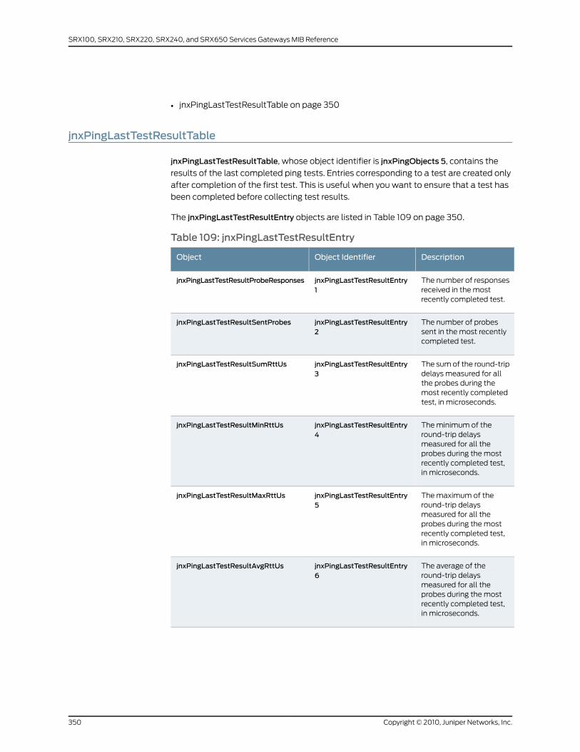
• jnxPingLastTestResultTable on page 350
jnxPingLastTestResultTable
jnxPingLastTestResultTable, whose object identifier is jnxPingObjects 5, contains the
results of the last completed ping tests. Entries corresponding to a test are created only
after completion of the first test. This is useful when you want to ensure that a test has
been completed before collecting test results.
The jnxPingLastTestResultEntry objects are listed in Table 109 on page 350.
Table 109: jnxPingLastTestResultEntry
DescriptionObject IdentifierObject
The number of responsesreceived in the mostrecently completed test.
jnxPingLastTestResultEntry1
jnxPingLastTestResultProbeResponses
The number of probessent in the most recentlycompleted test.
jnxPingLastTestResultEntry2
jnxPingLastTestResultSentProbes
The sum of the round-tripdelays measured for allthe probes during themost recently completedtest, in microseconds.
jnxPingLastTestResultEntry3
jnxPingLastTestResultSumRttUs
The minimum of theround-trip delaysmeasured for all theprobes during the mostrecently completed test,in microseconds.
jnxPingLastTestResultEntry4
jnxPingLastTestResultMinRttUs
The maximum of theround-trip delaysmeasured for all theprobes during the mostrecently completed test,in microseconds.
jnxPingLastTestResultEntry5
jnxPingLastTestResultMaxRttUs
The average of theround-trip delaysmeasured for all theprobes during the mostrecently completed test,in microseconds.
jnxPingLastTestResultEntry6
jnxPingLastTestResultAvgRttUs
Copyright © 2010, Juniper Networks, Inc.350
SRX100, SRX210, SRX220, SRX240, and SRX650 Services Gateways MIB Reference
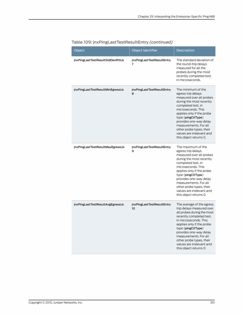
Table 109: jnxPingLastTestResultEntry (continued)
DescriptionObject IdentifierObject
The standard deviation ofthe round-trip delaysmeasured for all theprobes during the mostrecently completed test,in microseconds.
jnxPingLastTestResultEntry7
jnxPingLastTestResultStdDevRttUs
The minimum of theegress trip delaysmeasured over all probesduring the most recentlycompleted test, inmicroseconds. Thisapplies only if the probetype (pingCtlType)provides one-way delaymeasurements. For allother probe types, theirvalues are irrelevant andthis object returns 0.
jnxPingLastTestResultEntry8
jnxPingLastTestResultMinEgressUs
The maximum of theegress trip delaysmeasured over all probesduring the most recentlycompleted test, inmicroseconds. Thisapplies only if the probetype (pingCtlType)provides one-way delaymeasurements. For allother probe types, theirvalues are irrelevant andthis object returns 0.
jnxPingLastTestResultEntry9
jnxPingLastTestResultMaxEgressUs
The average of the egresstrip delays measured overall probes during the mostrecently completed test,in microseconds. Thisapplies only if the probetype (pingCtlType)provides one-way delaymeasurements. For allother probe types, theirvalues are irrelevant andthis object returns 0.
jnxPingLastTestResultEntry10
jnxPingLastTestResultAvgEgressUs
351Copyright © 2010, Juniper Networks, Inc.
Chapter 29: Interpreting the Enterprise-Specific Ping MIB
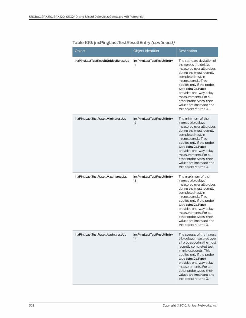
Table 109: jnxPingLastTestResultEntry (continued)
DescriptionObject IdentifierObject
The standard deviation ofthe egress trip delaysmeasured over all probesduring the most recentlycompleted test, inmicroseconds. Thisapplies only if the probetype (pingCtlType)provides one-way delaymeasurements. For allother probe types, theirvalues are irrelevant andthis object returns 0.
jnxPingLastTestResultEntry11
jnxPingLastTestResultStddevEgressUs
The minimum of theingress trip delaysmeasured over all probesduring the most recentlycompleted test, inmicroseconds. Thisapplies only if the probetype (pingCtlType)provides one-way delaymeasurements. For allother probe types, theirvalues are irrelevant andthis object returns 0.
jnxPingLastTestResultEntry12
jnxPingLastTestResultMinIngressUs
The maximum of theingress trip delaysmeasured over all probesduring the most recentlycompleted test, inmicroseconds. Thisapplies only if the probetype (pingCtlType)provides one-way delaymeasurements. For allother probe types, theirvalues are irrelevant andthis object returns 0.
jnxPingLastTestResultEntry13
jnxPingLastTestResultMaxIngressUs
The average of the ingresstrip delays measured overall probes during the mostrecently completed test,in microseconds. Thisapplies only if the probetype (pingCtlType)provides one-way delaymeasurements. For allother probe types, theirvalues are irrelevant andthis object returns 0.
jnxPingLastTestResultEntry14
jnxPingLastTestResultAvgIngressUs
Copyright © 2010, Juniper Networks, Inc.352
SRX100, SRX210, SRX220, SRX240, and SRX650 Services Gateways MIB Reference
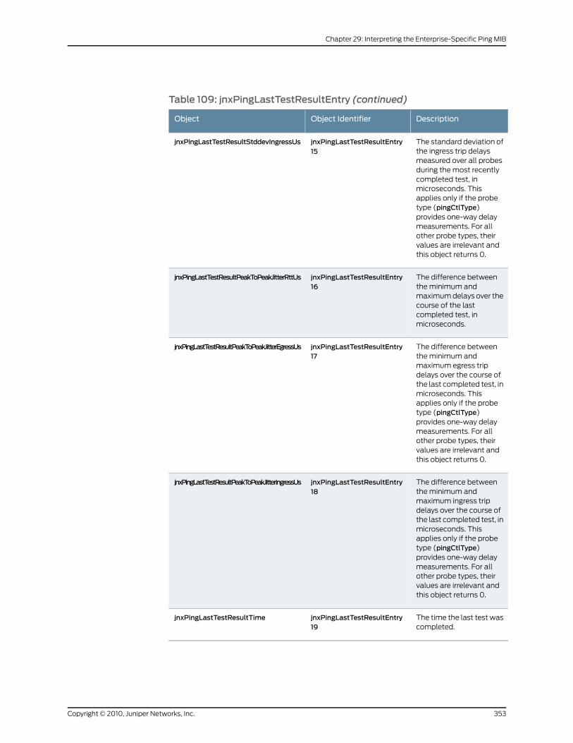
Table 109: jnxPingLastTestResultEntry (continued)
DescriptionObject IdentifierObject
The standard deviation ofthe ingress trip delaysmeasured over all probesduring the most recentlycompleted test, inmicroseconds. Thisapplies only if the probetype (pingCtlType)provides one-way delaymeasurements. For allother probe types, theirvalues are irrelevant andthis object returns 0.
jnxPingLastTestResultEntry15
jnxPingLastTestResultStddevIngressUs
The difference betweenthe minimum andmaximum delays over thecourse of the lastcompleted test, inmicroseconds.
jnxPingLastTestResultEntry16
jnxPingLastTestResultPeakToPeakJitterRttUs
The difference betweenthe minimum andmaximum egress tripdelays over the course ofthe last completed test, inmicroseconds. Thisapplies only if the probetype (pingCtlType)provides one-way delaymeasurements. For allother probe types, theirvalues are irrelevant andthis object returns 0.
jnxPingLastTestResultEntry17
jnxPingLastTestResultPeakToPeakJitterEgressUs
The difference betweenthe minimum andmaximum ingress tripdelays over the course ofthe last completed test, inmicroseconds. Thisapplies only if the probetype (pingCtlType)provides one-way delaymeasurements. For allother probe types, theirvalues are irrelevant andthis object returns 0.
jnxPingLastTestResultEntry18
jnxPingLastTestResultPeakToPeakJitterIngressUs
The time the last test wascompleted.
jnxPingLastTestResultEntry19
jnxPingLastTestResultTime
353Copyright © 2010, Juniper Networks, Inc.
Chapter 29: Interpreting the Enterprise-Specific Ping MIB

RelatedDocumentation
• PING MIB on page 339
• jnxPingCtlTable on page 340
• jnxPingResultsTable on page 344
• jnxPingProbeHistoryTable on page 348
Copyright © 2010, Juniper Networks, Inc.354
SRX100, SRX210, SRX220, SRX240, and SRX650 Services Gateways MIB Reference
CHAPTER 30
Interpreting theEnterprise-Specific PolicyObjects MIB
• Policy Objects MIB on page 355
• Security Policy Table on page 356
• jnxJsPolicyStatsTable on page 358
Policy Objects MIB
The Juniper Networks enterprise-specific Policy Objects MIB, jnxJsSecPolicyMIB, whose
object ID is {jnxJsPolicies 1}, defines the MIB for policy monitoring.
A security policy, which can be configured from the user interface, controls the traffic
flow from one zone to another zone by defining one or more kinds of traffic permitted
from specified IP sources to specified IP destinations at scheduled times.
The Juniper Networks security device enforces the security policies rules for the transit
traffic in terms of which traffic can pass through the firewall and the actions taken on
the traffic as it passes through the firewall.
Related MIB objects include the following:
• jnxJsPolicyNotifications—{jnxJsSecPolicyMIB 0}
• jnxJsPolicyObjects—{jnxJsSecPolicyMIB 1}
• jnxJsPolicyTrapVars—{jnxJsSecPolicyMIB 2}
For a downloadable version of this MIB, see
http://www.juniper.net/techpubs/en_US/junos10.4/topics/reference/mibs/mib-jnx-js-policy.txt
.
For information about the enterprise-specific Policy Objects MIB objects, see the following
topics:
• Security Policy Table on page 356
• jnxJsPolicyStatsTable on page 358
355Copyright © 2010, Juniper Networks, Inc.
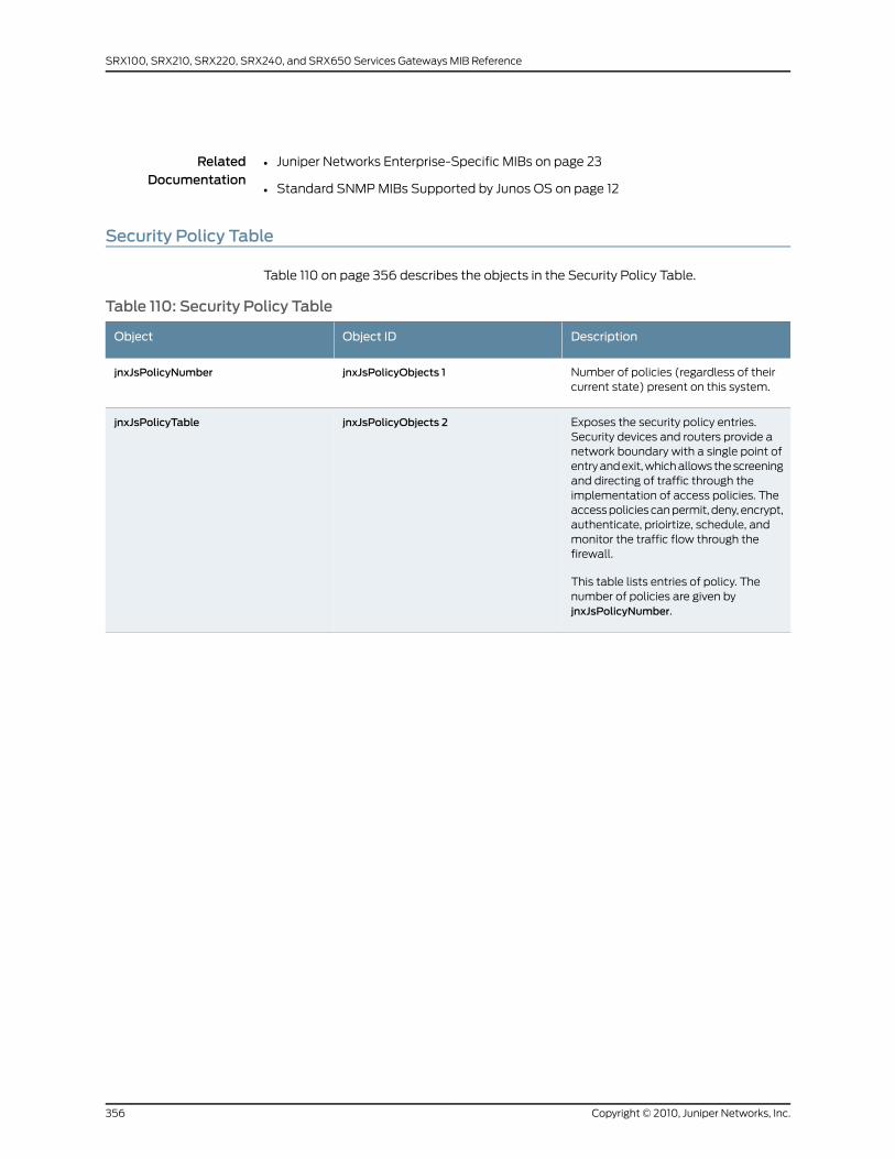
RelatedDocumentation
Juniper Networks Enterprise-Specific MIBs on page 23•
• Standard SNMP MIBs Supported by Junos OS on page 12
Security Policy Table
Table 110 on page 356 describes the objects in the Security Policy Table.
Table 110: Security Policy Table
DescriptionObject IDObject
Number of policies (regardless of theircurrent state) present on this system.
jnxJsPolicyObjects 1jnxJsPolicyNumber
Exposes the security policy entries.Security devices and routers provide anetwork boundary with a single point ofentry and exit, which allows the screeningand directing of traffic through theimplementation of access policies. Theaccess policies can permit, deny, encrypt,authenticate, prioirtize, schedule, andmonitor the traffic flow through thefirewall.
This table lists entries of policy. Thenumber of policies are given byjnxJsPolicyNumber.
jnxJsPolicyObjects 2jnxJsPolicyTable
Copyright © 2010, Juniper Networks, Inc.356
SRX100, SRX210, SRX220, SRX240, and SRX650 Services Gateways MIB Reference

Table 110: Security Policy Table (continued)
DescriptionObject IDObject
An entry contains a security policy.
Indexes:
• nxJsPolicyFromZone
• jnxJsPolicyToZone
• jnxJsPolicyName
Security policies are configured underFromZone and ToZone directions. Undera specific zone direction, each securitypolicy contains a name, match-criteria,action, and other options.
Sequence of parameters:
• jnxJsPolicyFromZone
• jnxJsPolicyToZone
• jnxJsPolicyName
• jnxJsPolicySequenceNumber
• jnxJsPolicyAction
• jnxJsPolicyScheduler
• jnxJsPolicyState
• jnxJsPolicyStatsAvailability
• jnxJsPolicyPerSecBytesThreshold
• jnxJsPolicyPerMinKbytesThreshold
jnxJsPolicyTable 1jnxJsPolicyEntry
FromZone name.jnxJsPolicyEntry 1jnxJsPolicyFromZone
ToZone name.jnxJsPolicyEntry 2jnxJsPolicyToZone
Name of the policy defined. The nameconsists of up to 256 ASCII charactersand uniquely identifies the policy entry.
jnxJsPolicyEntry 3jnxJsPolicyName
Indication of the policy sequence orderof the policy within a specific FromZoneand ToZone pair. Policies are matchedin a sequence in which the ordering isspecified by this number.
jnxJsPolicyEntry 4jnxJsPolicySequenceNumber
Indication of the actions performed whenthe criteria are matched.
The actions permit, reject, and deny areuser-configured policies.
jnxJsPolicyEntry 5jnxJsPolicyAction
Name of the schedule attached to thispolicy. Certain schedules have a specifiedduration that may affect the status ofthe policy.
jnxJsPolicyEntry 6jnxJsPolicyScheduler
357Copyright © 2010, Juniper Networks, Inc.
Chapter 30: Interpreting the Enterprise-Specific Policy Objects MIB
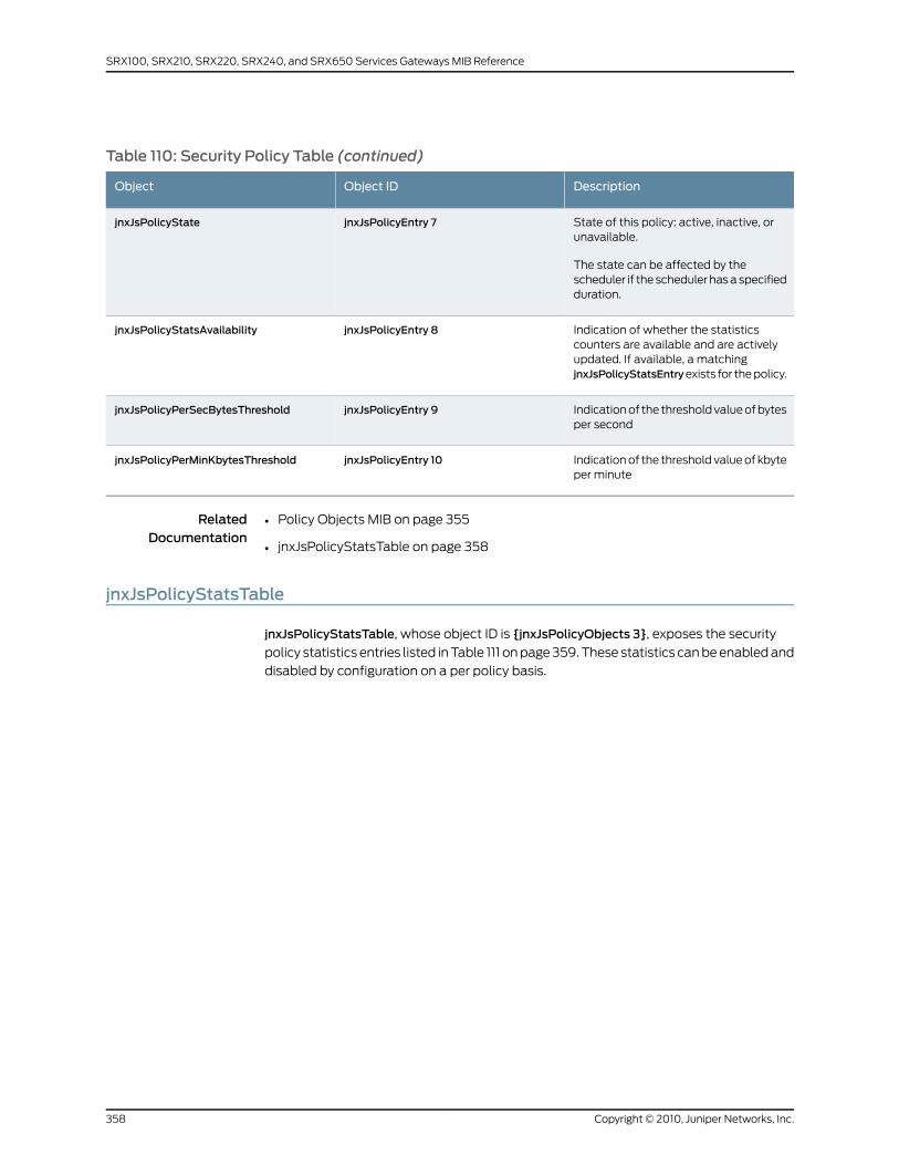
Table 110: Security Policy Table (continued)
DescriptionObject IDObject
State of this policy: active, inactive, orunavailable.
The state can be affected by thescheduler if the scheduler has a specifiedduration.
jnxJsPolicyEntry 7jnxJsPolicyState
Indication of whether the statisticscounters are available and are activelyupdated. If available, a matchingjnxJsPolicyStatsEntryexists for the policy.
jnxJsPolicyEntry 8jnxJsPolicyStatsAvailability
Indication of the threshold value of bytesper second
jnxJsPolicyEntry 9jnxJsPolicyPerSecBytesThreshold
Indication of the threshold value of kbyteper minute
jnxJsPolicyEntry 10jnxJsPolicyPerMinKbytesThreshold
RelatedDocumentation
Policy Objects MIB on page 355•
• jnxJsPolicyStatsTable on page 358
jnxJsPolicyStatsTable
jnxJsPolicyStatsTable, whose object ID is {jnxJsPolicyObjects 3}, exposes the security
policy statistics entries listed in Table 111 on page 359. These statistics can be enabled and
disabled by configuration on a per policy basis.
Copyright © 2010, Juniper Networks, Inc.358
SRX100, SRX210, SRX220, SRX240, and SRX650 Services Gateways MIB Reference
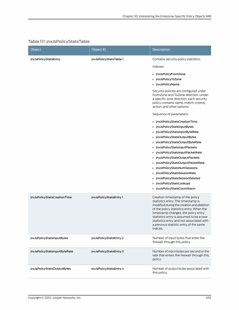
Table 111: jnxJsPolicyStatsTable
DescriptionObject IDObject
Contains security policy statistics.
Indexes:
• jnxJsPolicyFromZone
• jnxJsPolicyToZone
• jnxJsPolicyName
Security policies are configured underFromZone and ToZone direction. Undera specific zone direction, each securitypolicy contains name, match-criteria,action, and other options.
Sequence of parameters:
• jnxJsPolicyStatsCreationTime
• jnxJsPolicyStatsInputBytes
• jnxJsPolicyStatsInputByteRate
• jnxJsPolicyStatsOutputBytes
• jnxJsPolicyStatsOutputByteRate
• jnxJsPolicyStatsInputPackets
• jnxJsPolicyStatsInputPacketRate
• jnxJsPolicyStatsOutputPackets
• jnxJsPolicyStatsOutputPacketRate
• jnxJsPolicyStatsNumSessions
• jnxJsPolicyStatsSessionRate
• jnxJsPolicyStatsSessionDeleted
• jnxJsPolicyStatsLookups
• jnxJsPolicyStatsCountAlarm
jnxJsPolicyStatsTable 1jnxJsPolicyStatsEntry
Creation timestamp of the policystatistics entry. The timestamp ismodified during the creation and deletionof the policy statistics entry. When thetimestamp changes, the policy entrystatistics entry is assumed to be a newstatistics entry and not associated witha previous statistic entry of the sameindices.
jnxJsPolicyStatsEntry 1jnxJsPolicyStatsCreationTime
Number of input bytes that enter thefirewall through this policy.
jnxJsPolicyStatsEntry 2jnxJsPolicyStatsInputBytes
Number of input bytes per second or therate that enters the firewall through thispolicy.
jnxJsPolicyStatsEntry 3jnxJsPolicyStatsInputByteRate
Number of output bytes associated withthis policy.
jnxJsPolicyStatsEntry 4jnxJsPolicyStatsOutputBytes
359Copyright © 2010, Juniper Networks, Inc.
Chapter 30: Interpreting the Enterprise-Specific Policy Objects MIB

Table 111: jnxJsPolicyStatsTable (continued)
DescriptionObject IDObject
Number of output bytes per second orthe rate associated with this policy.
jnxJsPolicyStatsEntry 5jnxJsPolicyStatsOutputByteRate
Number of input packets that enter thefirewall through this policy.
jnxJsPolicyStatsEntry 6jnxJsPolicyStatsInputPackets
Number of input packets per second orthe input packet rate of the firewallthrough this policy.
jnxJsPolicyStatsEntry 7jnxJsPolicyStatsInputPacketRate
Number of output packets associatedwith this policy.
jnxJsPolicyStatsEntry 8jnxJsPolicyStatsOutputPackets
Number of output packets per second orthe rate associated with this policy.
jnxJsPolicyStatsEntry 9jnxJsPolicyStatsOutputPacketRate
Number of sessions associated with thispolicy.
jnxJsPolicyStatsEntry 10jnxJsPolicyStatsNumSessions
Rate of the sessions associated with thispolicy.
jnxJsPolicyStatsEntry 11jnxJsPolicyStatsSessionRate
Number of sessions associated with thispolicy.
jnxJsPolicyStatsEntry 12jnxJsPolicyStatsSessionDeleted
Number of policy lookups performed.jnxJsPolicyStatsEntry 13jnxJsPolicyStatsLookups
Number of alarms counted when thetraffic exceeds a certain thresholdconfiguration.
jnxJsPolicyStatsEntry 14jnxJsPolicyStatsCountAlarm
RelatedDocumentation
• Policy Objects MIB on page 355
• Security Policy Table on page 356
Copyright © 2010, Juniper Networks, Inc.360
SRX100, SRX210, SRX220, SRX240, and SRX650 Services Gateways MIB Reference

CHAPTER 31
Interpreting the Enterprise-SpecificReal-Time Media MIB
• Real-Time Media MIB Overview on page 361
• SIP Template on page 362
• Analog Template on page 363
• Peer Call Server on page 363
• Survivable Call Service on page 364
• Trunk Configuration on page 365
• Digit Manipulation on page 366
• Attendant Features on page 366
• Station Configuration on page 367
• Dial Plan Configuration on page 367
• Class of Restriction on page 368
• Media Gateway Configuration on page 368
• Trunk Group Configuration on page 369
• Survivable Call Service Statistics on page 369
Real-TimeMedia MIB Overview
The Juniper Networks enterprise-specific Real-Time Media (RTM) MIB, whose object
identifier is { jnxVoip 1 }, defines an RTM configuration.
For a downloadable version of the RTM MIB, see
http://www.juniper.net/techpubs/en_US/junos10.4/topics/reference/mibs/mib-jnx-rtm.txt
.
For more information about the enterprise-specific RTM MIBs, see the following topics:
• SIP Template on page 362
• Analog Template on page 363
• Peer Call Server on page 363
• Survivable Call Service on page 364
361Copyright © 2010, Juniper Networks, Inc.
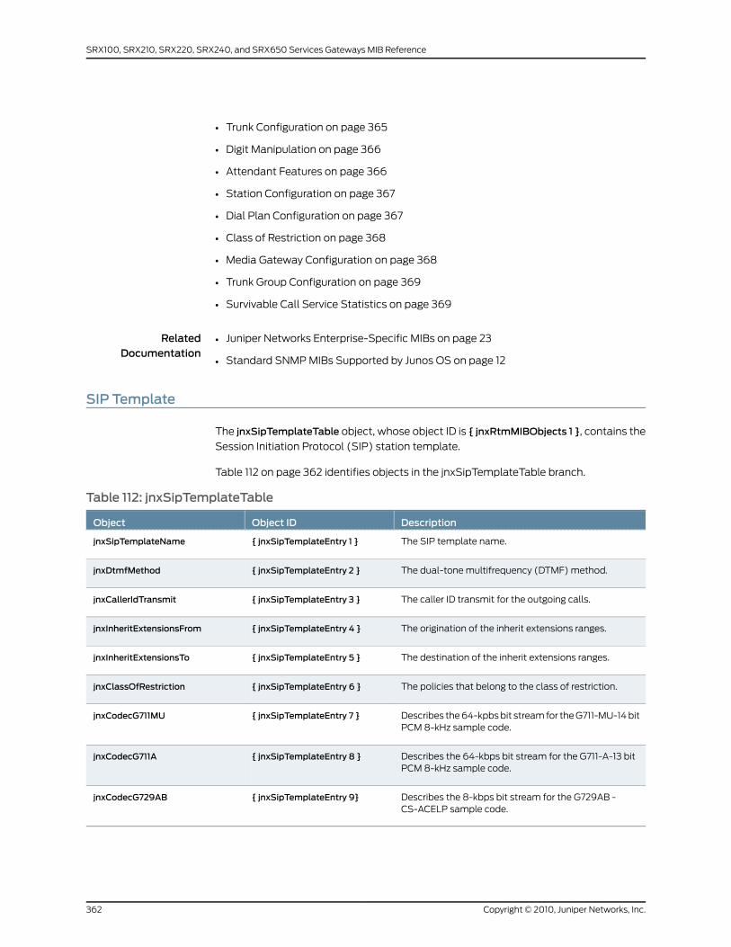
• Trunk Configuration on page 365
• Digit Manipulation on page 366
• Attendant Features on page 366
• Station Configuration on page 367
• Dial Plan Configuration on page 367
• Class of Restriction on page 368
• Media Gateway Configuration on page 368
• Trunk Group Configuration on page 369
• Survivable Call Service Statistics on page 369
RelatedDocumentation
Juniper Networks Enterprise-Specific MIBs on page 23•
• Standard SNMP MIBs Supported by Junos OS on page 12
SIP Template
The jnxSipTemplateTable object, whose object ID is { jnxRtmMIBObjects 1 }, contains the
Session Initiation Protocol (SIP) station template.
Table 112 on page 362 identifies objects in the jnxSipTemplateTable branch.
Table 112: jnxSipTemplateTable
DescriptionObject IDObject
The SIP template name.{ jnxSipTemplateEntry 1 }jnxSipTemplateName
The dual-tone multifrequency (DTMF) method.{ jnxSipTemplateEntry 2 }jnxDtmfMethod
The caller ID transmit for the outgoing calls.{ jnxSipTemplateEntry 3 }jnxCallerIdTransmit
The origination of the inherit extensions ranges.{ jnxSipTemplateEntry 4 }jnxInheritExtensionsFrom
The destination of the inherit extensions ranges.{ jnxSipTemplateEntry 5 }jnxInheritExtensionsTo
The policies that belong to the class of restriction.{ jnxSipTemplateEntry 6 }jnxClassOfRestriction
Describes the 64-kpbs bit stream for the G711-MU-14 bitPCM 8-kHz sample code.
{ jnxSipTemplateEntry 7 }jnxCodecG711MU
Describes the 64-kbps bit stream for the G711-A-13 bitPCM 8-kHz sample code.
{ jnxSipTemplateEntry 8 }jnxCodecG711A
Describes the 8-kbps bit stream for the G729AB -CS-ACELP sample code.
{ jnxSipTemplateEntry 9}jnxCodecG729AB
Copyright © 2010, Juniper Networks, Inc.362
SRX100, SRX210, SRX220, SRX240, and SRX650 Services Gateways MIB Reference
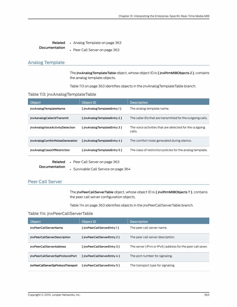
RelatedDocumentation
Analog Template on page 363•
• Peer Call Server on page 363
Analog Template
The jnxAnalogTemplateTable object, whose object ID is { jnxRtmMIBObjects 2 }, contains
the analog template objects.
Table 113 on page 363 identifies objects in the jnxAnalogTemplateTable branch.
Table 113: jnxAnalogTemplateTable
DescriptionObject IDObject
The analog template name.{ jnxAnalogTemplateEntry 1 }jnxAnalogTemplateName
The caller IDs that are transmitted for the outgoing calls.{ jnxAnalogTemplateEntry 2 }jnxAanalogCallerIdTransmit
The voice activities that are detected for the outgoingcalls.
{ jnxAnalogTemplateEntry 3 }jnxAnalogVoiceActivityDetection
The comfort noise generated during silence.{ jnxAnalogTemplateEntry 4 }jnxAnalogComfortNoiseGeneration
The class of restriction policies for the analog template.{ jnxAnalogTemplateEntry 5 }jnxAnalogClassOfRestriction
RelatedDocumentation
Peer Call Server on page 363•
• Survivable Call Service on page 364
Peer Call Server
The jnxPeerCallServerTable object, whose object ID is { jnxRtmMIBObjects 7 }, contains
the peer call server configuration objects.
Table 114 on page 363 identifies objects in the jnxPeerCallServerTable branch.
Table 114: jnxPeerCallServerTable
DescriptionObject IDObject
The peer call server name.{ jnxPeerCallServerEntry 1 }jnxPeerCallServerName
The peer call server description.{ jnxPeerCallServerEntry 2 }jnxPeerCallServerDescription
The server (IPv4 or IPv6) address for the peer call sever.{ jnxPeerCallServerEntry 3 }jnxPeerCallServerAddress
The port number for signaling.{ jnxPeerCallServerEntry 4 }jnxPeerCallServerSipProtocolPort
The transport type for signaling.{ jnxPeerCallServerEntry 5 }jnxPeerCallServerSipProtocolTransport
363Copyright © 2010, Juniper Networks, Inc.
Chapter 31: Interpreting the Enterprise-Specific Real-Time Media MIB
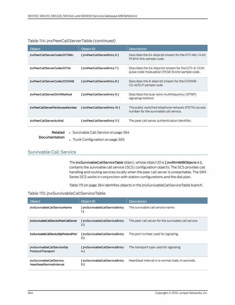
Table 114: jnxPeerCallServerTable (continued)
DescriptionObject IDObject
Describes the 64-kbps bit stream for the G711-MU-14 bitPCM 8-kHz sample code.
{ jnxPeerCallServerEntry 6 }jnxPeerCallServerCodecG711MU
Describes the 64-kbps bit stream for the G711-A-13 bitpulse code modulation (PCM) 8-kHz sample code.
{ jnxPeerCallServerEntry 7 }jnxPeerCallServerCodecG711A
Describes the 8-kbps bit stream for the G729AB -CS-ACELP sample code.
{ jnxPeerCallServerEntry 8 }jnxPeerCallServerCodecG729AB
Describes the dual-tone multifrequency (DTMF)signaling method.
{ jnxPeerCallServerEntry 9 }jnxPeerCallServerDtmfMethod
The public switched telephone network (PSTN) accessnumber for the survivable call service.
{ jnxPeerCallServerEntry 10 }jnxPeerCallServerPstnAccessNumber
The peer call server authentication identifier.{ jnxPeerCallServerEntry 11 }jnxPeerCallServerAuthId
RelatedDocumentation
Survivable Call Service on page 364•
• Trunk Configuration on page 365
Survivable Call Service
The jnxSurvivableCallServiceTable object, whose object ID is { jnxRtmMIBObjects 4 },
contains the survivable call service (SCS) configuration objects. The SCS provides call
handling and routing services locally when the peer call server is unreachable. The SRX
Series SCS works in conjunction with station configurations and the dial plan.
Table 115 on page 364 identifies objects in the jnxSurvivableCallServiceTable branch.
Table 115: jnxSurvivableCallServiceTable
DescriptionObject IDObject
The survivable call service name.{ jnxSurvivableCallServiceEntry1 }
jnxSurvivableCallServiceName
The peer call server for the survivable call service.{ jnxSurvivableCallServiceEntry2 }
jnxSurvivableCallServicePeerCallServer
The port number used for signaling.{ jnxSurvivableCallServiceEntry3 }
jnxSurvivableCallServiceSipProtocolPort
The transport type used for signaling.{ jnxSurvivableCallServiceEntry4 }
jnxSurvivableCallServiceSipProtocolTransport
Heartbeat interval in a normal state, in seconds.{ jnxSurvivableCallServiceEntry5 }
jnxSurvivableCallServiceHeartbeatNormalInterval
Copyright © 2010, Juniper Networks, Inc.364
SRX100, SRX210, SRX220, SRX240, and SRX650 Services Gateways MIB Reference
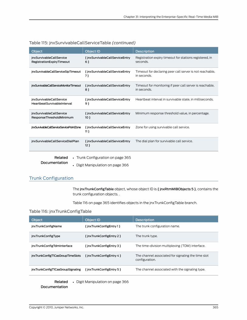
Table 115: jnxSurvivableCallServiceTable (continued)
DescriptionObject IDObject
Registration expiry timeout for stations registered, inseconds.
{ jnxSurvivableCallServiceEntry6 }
jnxSurvivableCallServiceRegistrationExpiryTimeout
Timeout for declaring peer call server is not reachable,in seconds.
{ jnxSurvivableCallServiceEntry7 }
jnxSurvivableCallServiceSipTimeout
Timeout for monitoring if peer call server is reachable,in seconds.
{ jnxSurvivableCallServiceEntry8 }
jnxSurvivableCallServiceMonitorTimeout
Heartbeat interval in survivable state, in milliseconds.{ jnxSurvivableCallServiceEntry9 }
jnxSurvivableCallServiceHeartbeatSurvivableInterval
Minimum response threshold value, in percentage.{ jnxSurvivableCallServiceEntry10 }
jnxSurvivableCallServiceResponseThresholdMinimum
Zone for using survivable call service.{ jnxSurvivableCallServiceEntry11 }
jnxSurvivableCallServiceServicePointZone
The dial plan for survivable call service.{ jnxSurvivableCallServiceEntry12 }
jnxSurvivableCallServiceDialPlan
RelatedDocumentation
Trunk Configuration on page 365•
• Digit Manipulation on page 366
Trunk Configuration
The jnxTrunkConfigTable object, whose object ID is { jnxRtmMIBObjects 5 }, contains the
trunk configuration objects. .
Table 116 on page 365 identifies objects in the jnxTrunkConfigTable branch.
Table 116: jnxTrunkConfigTable
DescriptionObject IDObject
The trunk configuration name.{ jnxTrunkConfigEntry 1 }jnxTrunkConfigName
The trunk type.{ jnxTrunkConfigEntry 2 }jnxTrunkConfigType
The time-division multiplexing (TDM) interface.{ jnxTrunkConfigEntry 3 }jnxTrunkConfigTdmInterface
The channel associated for signaling the time slotconfiguration.
{ jnxTrunkConfigEntry 4 }jnxTrunkConfigT1CasGroupTimeSlots
The channel associated with the signaling type.{ jnxTrunkConfigEntry 5 }jnxTrunkConfigT1CasGroupSignaling
RelatedDocumentation
Digit Manipulation on page 366•
365Copyright © 2010, Juniper Networks, Inc.
Chapter 31: Interpreting the Enterprise-Specific Real-Time Media MIB
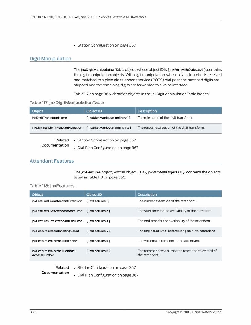
• Station Configuration on page 367
Digit Manipulation
The jnxDigitManipulationTableobject, whose object ID is { jnxRtmMIBObjects6}, contains
the digit manipulation objects. With digit manipulation, when a dialed number is received
and matched to a plain old telephone service (POTS) dial peer, the matched digits are
stripped and the remaining digits are forwarded to a voice interface.
Table 117 on page 366 identifies objects in the jnxDigitManipulationTable branch.
Table 117: jnxDigitManipulationTable
DescriptionObject IDObject
The rule name of the digit transform.{ jnxDigitManipulationEntry 1 }jnxDigitTransformName
The regular expression of the digit transform.{ jnxDigitManipulationEntry 2 }jnxDigitTransformRegularExpression
RelatedDocumentation
Station Configuration on page 367•
• Dial Plan Configuration on page 367
Attendant Features
The jnxFeatures object, whose object ID is { jnxRtmMIBObjects 8 }, contains the objects
listed in Table 118 on page 366.
Table 118: jnxFeatures
DescriptionObject IDObject
The current extension of the attendant.{ jnxFeatures 1 }jnxFeaturesLiveAttendantExtension
The start time for the availability of the attendant.{ jnxFeatures 2 }jnxFeaturesLiveAttendantStartTime
The end time for the availability of the attendant.{ jnxFeatures 3 }jnxFeaturesLiveAttendantEndTime
The ring count wait, before using an auto-attendant.{ jnxFeatures 4 }jnxFeaturesAttendantRingCount
The voicemail extension of the attendant.{ jnxFeatures 5 }jnxFeaturesVoicemailExtension
The remote access number to reach the voice mail ofthe attendant.
{ jnxFeatures 6 }jnxFeaturesVoicemailRemoteAccessNumber
RelatedDocumentation
Station Configuration on page 367•
• Dial Plan Configuration on page 367
Copyright © 2010, Juniper Networks, Inc.366
SRX100, SRX210, SRX220, SRX240, and SRX650 Services Gateways MIB Reference

Station Configuration
The jnxStationTable object, whose object ID is { jnxRtmMIBObjects 3 }, contains the
station configuration objects. .
Table 119 on page 367 identifies objects in the jnxStationTable branch.
Table 119: jnxStationTable
DescriptionObject IDObject
The station name.{ jnxStationEntry 1 }jnxStationName
The station extension.{ jnxStationEntry 2 }jnxStationExtension
The class of restriction for the station.{ jnxStationEntry 3 }jnxStationRestriction
The caller ID of the station.{ jnxStationEntry 5 }jnxStationCallerId
The direct inward dialing (DID) number for the station.{ jnxStationEntry 6 }jnxStationDID
The direct inward line time-division multiplexing (TDM)interface for the station.
{ jnxStationEntry 7 }jnxStationDILTdmInterface
Direct inward line time slot number for the station.{ jnxStationEntry 8 }jnxStationDILTimeSlotNumber
Authentication identifier of the station.{ jnxStationEntry 9 }jnxStationAuthId
The station type.{ jnxStationEntry 10 }jnxStationType
The template name of the station.{ jnxStationEntry 11 }jnxStationTemplate
The TDM interface of the station. If the station type isSession Initiation Protocol (SIP), the object is notapplicable and contains a null string.
{ jnxStationEntry 12 }jnxStationTdmInterface
The time slot number for the station. If the station typeis SIP, the object is not applicable.
{ jnxStationEntry 13 }jnxStationTimeSlotNumber
RelatedDocumentation
Dial Plan Configuration on page 367•
• Class of Restriction on page 368
Dial Plan Configuration
The jnxDialPlanTable object, whose object ID is { jnxRtmMIBObjects 9 }, contains the dial
plan for survivable call service configuration objects.
Table 120 on page 368 identifies objects in the jnxDialPlanTable branch.
367Copyright © 2010, Juniper Networks, Inc.
Chapter 31: Interpreting the Enterprise-Specific Real-Time Media MIB
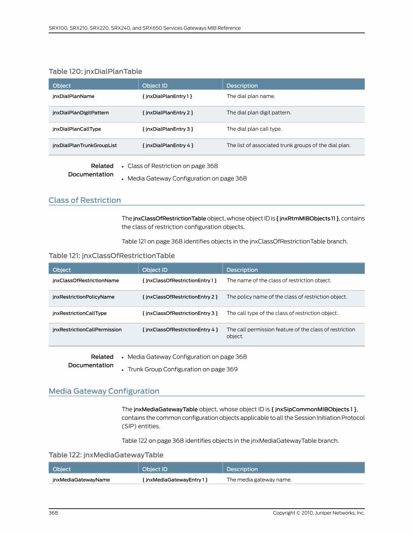
Table 120: jnxDialPlanTable
DescriptionObject IDObject
The dial plan name.{ jnxDialPlanEntry 1 }jnxDialPlanName
The dial plan digit pattern.{ jnxDialPlanEntry 2 }jnxDialPlanDigitPattern
The dial plan call type.{ jnxDialPlanEntry 3 }jnxDialPlanCallType
The list of associated trunk groups of the dial plan.{ jnxDialPlanEntry 4 }jnxDialPlanTrunkGroupList
RelatedDocumentation
Class of Restriction on page 368•
• Media Gateway Configuration on page 368
Class of Restriction
The jnxClassOfRestrictionTableobject, whose object ID is { jnxRtmMIBObjects 11}, contains
the class of restriction configuration objects.
Table 121 on page 368 identifies objects in the jnxClassOfRestrictionTable branch.
Table 121: jnxClassOfRestrictionTable
DescriptionObject IDObject
The name of the class of restriction object.{ jnxClassOfRestrictionEntry 1 }jnxClassOfRestrictionName
The policy name of the class of restriction object.{ jnxClassOfRestrictionEntry 2 }jnxRestrictionPolicyName
The call type of the class of restriction object.{ jnxClassOfRestrictionEntry 3 }jnxRestrictionCallType
The call permission feature of the class of restrictionobject.
{ jnxClassOfRestrictionEntry 4 }jnxRestrictionCallPermission
RelatedDocumentation
Media Gateway Configuration on page 368•
• Trunk Group Configuration on page 369
Media Gateway Configuration
The jnxMediaGatewayTable object, whose object ID is { jnxSipCommonMIBObjects 1 },
contains the common configuration objects applicable to all the Session Initiation Protocol
(SIP) entities.
Table 122 on page 368 identifies objects in the jnxMediaGatewayTable branch.
Table 122: jnxMediaGatewayTable
DescriptionObject IDObject
The media gateway name.{ jnxMediaGatewayEntry 1 }jnxMediaGatewayName
Copyright © 2010, Juniper Networks, Inc.368
SRX100, SRX210, SRX220, SRX240, and SRX650 Services Gateways MIB Reference
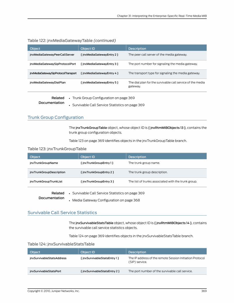
Table 122: jnxMediaGatewayTable (continued)
DescriptionObject IDObject
The peer call server of the media gateway.{ jnxMediaGatewayEntry 2 }jnxMediaGatewayPeerCallServer
The port number for signaling the media gateway.{ jnxMediaGatewayEntry 3 }jnxMediaGatewaySipProtocolPort
The transport type for signaling the media gateway.{ jnxMediaGatewayEntry 4 }jnxMediaGatewaySipProtocolTransport
The dial plan for the survivable call service of the mediagateway.
{ jnxMediaGatewayEntry 5 }jnxMediaGatewayDialPlan
RelatedDocumentation
Trunk Group Configuration on page 369•
• Survivable Call Service Statistics on page 369
Trunk Group Configuration
The jnxTrunkGroupTable object, whose object ID is { jnxRtmMIBObjects 13 }, contains the
trunk group configuration objects.
Table 123 on page 369 identifies objects in the jnxTrunkGroupTable branch.
Table 123: jnxTrunkGroupTable
DescriptionObject IDObject
The trunk group name.{ jnxTrunkGroupEntry 1 }jnxTrunkGroupName
The trunk group description.{ jnxTrunkGroupEntry 2 }jnxTrunkGroupDescription
The list of trunks associated with the trunk group.{ jnxTrunkGroupEntry 3 }jnxTrunkGroupTrunkList
RelatedDocumentation
Survivable Call Service Statistics on page 369•
• Media Gateway Configuration on page 368
Survivable Call Service Statistics
The jnxSurvivableStatsTable object, whose object ID is { jnxRtmMIBObjects 14 }, contains
the survivable call service statistics objects.
Table 124 on page 369 identifies objects in the jnxSurvivableStatsTable branch.
Table 124: jnxSurvivableStatsTable
DescriptionObject IDObject
The IP address of the remote Session Initiation Protocol(SIP) service.
{ jnxSurvivableStatsEntry 1 }jnxSurvivableStatsAddress
The port number of the survivable call service.{ jnxSurvivableStatsEntry 2 }jnxSurvivableStatsPort
369Copyright © 2010, Juniper Networks, Inc.
Chapter 31: Interpreting the Enterprise-Specific Real-Time Media MIB
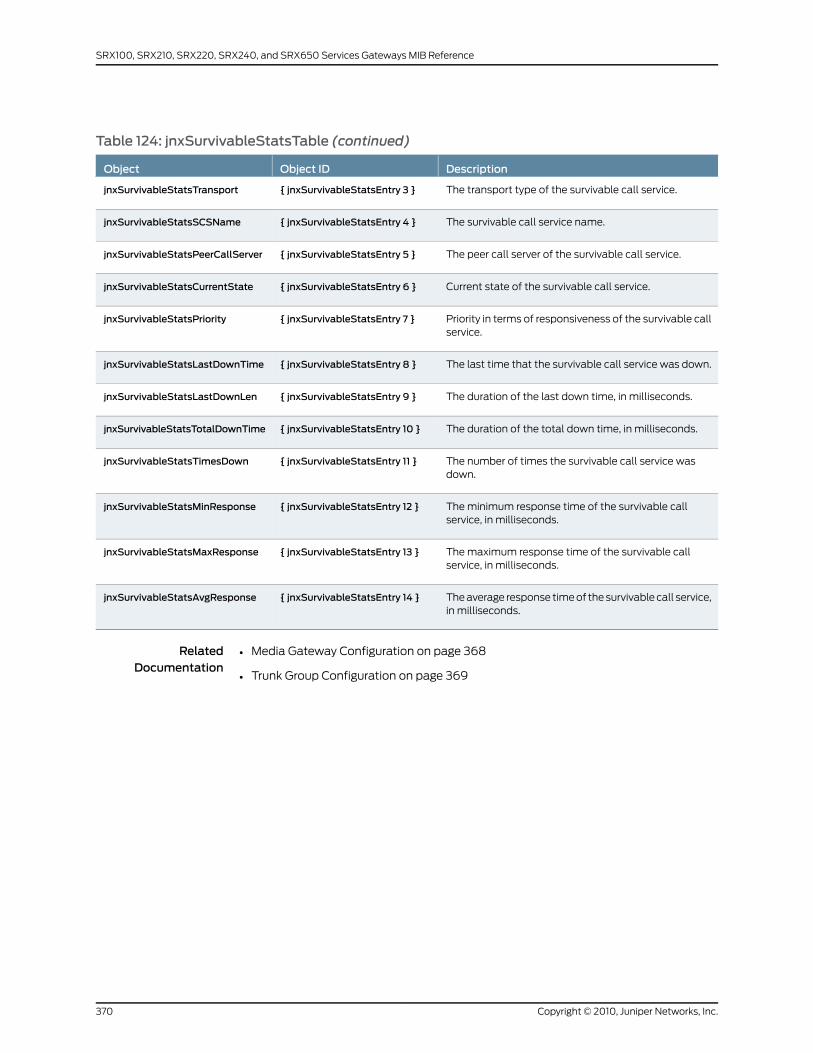
Table 124: jnxSurvivableStatsTable (continued)
DescriptionObject IDObject
The transport type of the survivable call service.{ jnxSurvivableStatsEntry 3 }jnxSurvivableStatsTransport
The survivable call service name.{ jnxSurvivableStatsEntry 4 }jnxSurvivableStatsSCSName
The peer call server of the survivable call service.{ jnxSurvivableStatsEntry 5 }jnxSurvivableStatsPeerCallServer
Current state of the survivable call service.{ jnxSurvivableStatsEntry 6 }jnxSurvivableStatsCurrentState
Priority in terms of responsiveness of the survivable callservice.
{ jnxSurvivableStatsEntry 7 }jnxSurvivableStatsPriority
The last time that the survivable call service was down.{ jnxSurvivableStatsEntry 8 }jnxSurvivableStatsLastDownTime
The duration of the last down time, in milliseconds.{ jnxSurvivableStatsEntry 9 }jnxSurvivableStatsLastDownLen
The duration of the total down time, in milliseconds.{ jnxSurvivableStatsEntry 10 }jnxSurvivableStatsTotalDownTime
The number of times the survivable call service wasdown.
{ jnxSurvivableStatsEntry 11 }jnxSurvivableStatsTimesDown
The minimum response time of the survivable callservice, in milliseconds.
{ jnxSurvivableStatsEntry 12 }jnxSurvivableStatsMinResponse
The maximum response time of the survivable callservice, in milliseconds.
{ jnxSurvivableStatsEntry 13 }jnxSurvivableStatsMaxResponse
The average response time of the survivable call service,in milliseconds.
{ jnxSurvivableStatsEntry 14 }jnxSurvivableStatsAvgResponse
RelatedDocumentation
• Media Gateway Configuration on page 368
• Trunk Group Configuration on page 369
Copyright © 2010, Juniper Networks, Inc.370
SRX100, SRX210, SRX220, SRX240, and SRX650 Services Gateways MIB Reference
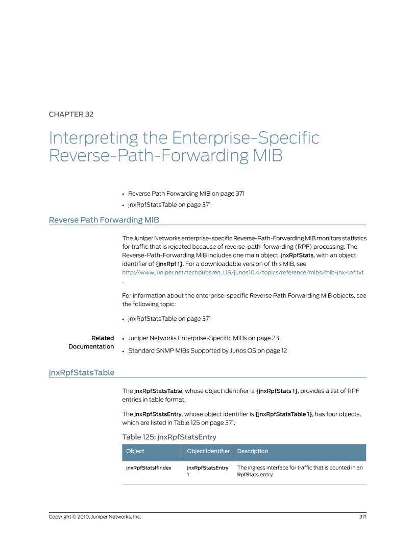
CHAPTER 32
Interpreting the Enterprise-SpecificReverse-Path-Forwarding MIB
• Reverse Path Forwarding MIB on page 371
• jnxRpfStatsTable on page 371
Reverse Path ForwardingMIB
The Juniper Networks enterprise-specific Reverse-Path-Forwarding MIB monitors statistics
for traffic that is rejected because of reverse-path-forwarding (RPF) processing. The
Reverse-Path-Forwarding MIB includes one main object, jnxRpfStats, with an object
identifier of {jnxRpf 1}. For a downloadable version of this MIB, see
http://www.juniper.net/techpubs/en_US/junos10.4/topics/reference/mibs/mib-jnx-rpf.txt
.
For information about the enterprise-specific Reverse Path Forwarding MIB objects, see
the following topic:
• jnxRpfStatsTable on page 371
RelatedDocumentation
Juniper Networks Enterprise-Specific MIBs on page 23•
• Standard SNMP MIBs Supported by Junos OS on page 12
jnxRpfStatsTable
The jnxRpfStatsTable, whose object identifier is {jnxRpfStats 1}, provides a list of RPF
entries in table format.
The jnxRpfStatsEntry, whose object identifier is {jnxRpfStatsTable 1}, has four objects,
which are listed in Table 125 on page 371.
Table 125: jnxRpfStatsEntry
DescriptionObject IdentifierObject
The ingress interface for traffic that is counted in anRpfStats entry.
jnxRpfStatsEntry1
jnxRpfStatsIfIndex
371Copyright © 2010, Juniper Networks, Inc.
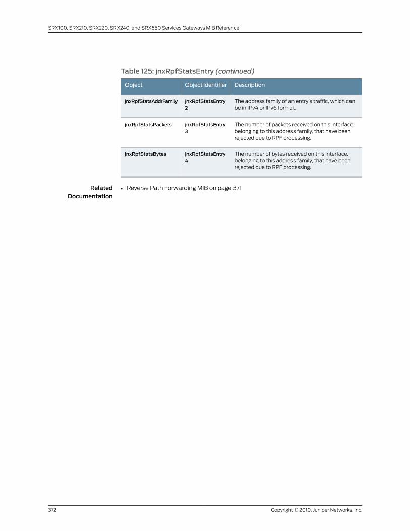
Table 125: jnxRpfStatsEntry (continued)
DescriptionObject IdentifierObject
The address family of an entry’s traffic, which canbe in IPv4 or IPv6 format.
jnxRpfStatsEntry2
jnxRpfStatsAddrFamily
The number of packets received on this interface,belonging to this address family, that have beenrejected due to RPF processing.
jnxRpfStatsEntry3
jnxRpfStatsPackets
The number of bytes received on this interface,belonging to this address family, that have beenrejected due to RPF processing.
jnxRpfStatsEntry4
jnxRpfStatsBytes
RelatedDocumentation
• Reverse Path Forwarding MIB on page 371
Copyright © 2010, Juniper Networks, Inc.372
SRX100, SRX210, SRX220, SRX240, and SRX650 Services Gateways MIB Reference
CHAPTER 33
Interpreting theEnterprise-SpecificRMONEvents and Alarms MIB
• RMON Events and Alarms MIB on page 373
• jnxRmonAlarmTable on page 374
• RMON Event and Alarm Traps on page 375
RMON Events and AlarmsMIB
The Juniper Networks enterprise-specific Remote Monitoring (RMON) Events and Alarms
MIB monitors objects on a device and warns the network system administrator if one of
those values exceeds the defined range. The alarm monitors objects in this MIB and
triggers an event when the condition (falling or rising threshold) is reached.
The Juniper Networks enterprise-specific extension to the standard RMON MIB augments
the alarmTable with additional information about each alarm. Two new traps,
jnxRmonAlarmGetFailureand jnxRmonGetOk, are also defined to indicate when problems
are encountered with an alarm.
To view a complete copy of the enterprise-specific extensions to the RMON MIB, see
http://www.juniper.net/techpubs/en_US/junos10.4/topics/reference/mibs/mib-jnx-rmon.txt
.
For more information about RMON alarms and events, see the Junos OS Network
Management Configuration Guide.
For information about the enterprise-specific RMON Events and Alarms MIB objects, see
the following topics:
• jnxRmonAlarmTable on page 374
• RMON Event and Alarm Traps on page 375
RelatedDocumentation
Juniper Networks Enterprise-Specific MIBs on page 23•
• Standard SNMP MIBs Supported by Junos OS on page 12
373Copyright © 2010, Juniper Networks, Inc.
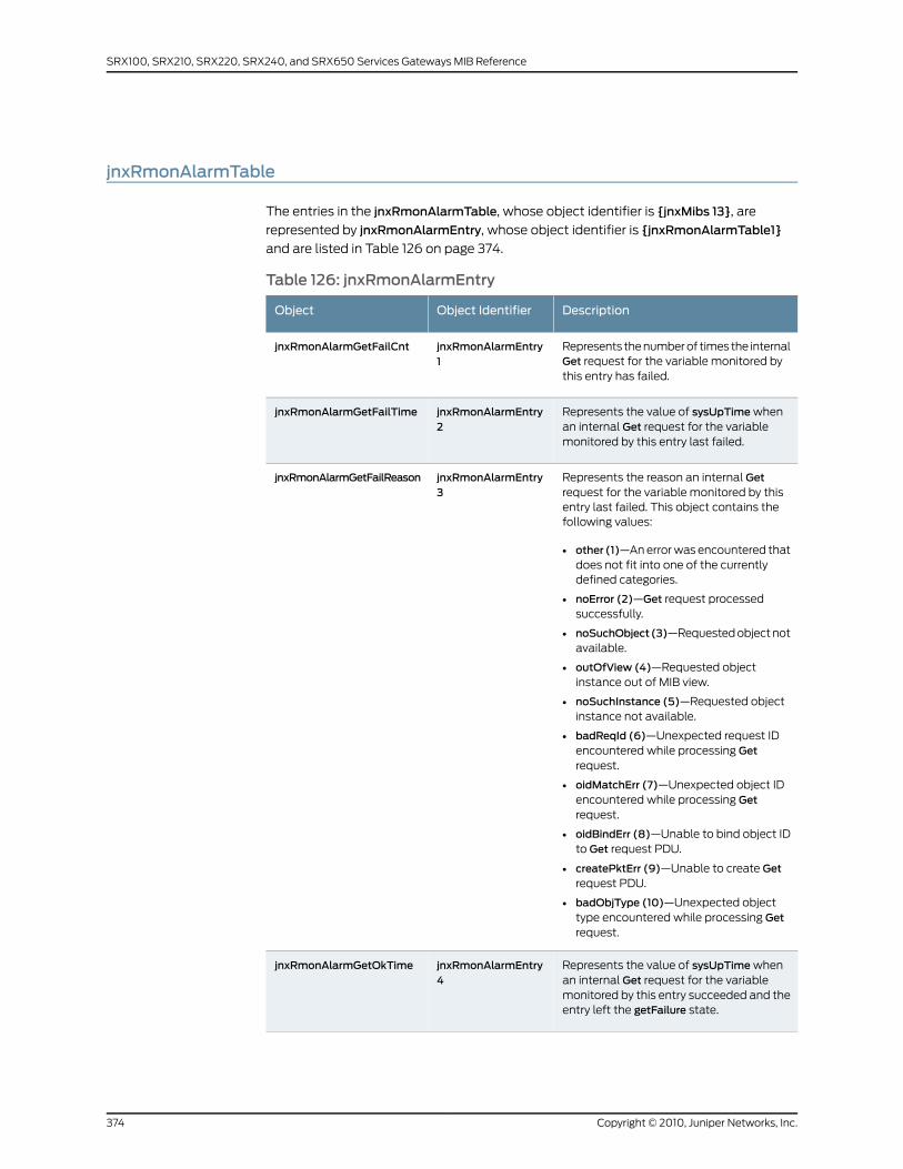
jnxRmonAlarmTable
The entries in the jnxRmonAlarmTable, whose object identifier is {jnxMibs 13}, are
represented by jnxRmonAlarmEntry, whose object identifier is {jnxRmonAlarmTable1}
and are listed in Table 126 on page 374.
Table 126: jnxRmonAlarmEntry
DescriptionObject IdentifierObject
Represents the number of times the internalGet request for the variable monitored bythis entry has failed.
jnxRmonAlarmEntry1
jnxRmonAlarmGetFailCnt
Represents the value of sysUpTime whenan internal Get request for the variablemonitored by this entry last failed.
jnxRmonAlarmEntry2
jnxRmonAlarmGetFailTime
Represents the reason an internal Getrequest for the variable monitored by thisentry last failed. This object contains thefollowing values:
• other (1)—An error was encountered thatdoes not fit into one of the currentlydefined categories.
• noError (2)—Get request processedsuccessfully.
• noSuchObject(3)—Requested object notavailable.
• outOfView (4)—Requested objectinstance out of MIB view.
• noSuchInstance (5)—Requested objectinstance not available.
• badReqId (6)—Unexpected request IDencountered while processing Getrequest.
• oidMatchErr (7)—Unexpected object IDencountered while processing Getrequest.
• oidBindErr (8)—Unable to bind object IDto Get request PDU.
• createPktErr (9)—Unable to create Getrequest PDU.
• badObjType (10)—Unexpected objecttype encountered while processing Getrequest.
jnxRmonAlarmEntry3
jnxRmonAlarmGetFailReason
Represents the value of sysUpTime whenan internal Get request for the variablemonitored by this entry succeeded and theentry left the getFailure state.
jnxRmonAlarmEntry4
jnxRmonAlarmGetOkTime
Copyright © 2010, Juniper Networks, Inc.374
SRX100, SRX210, SRX220, SRX240, and SRX650 Services Gateways MIB Reference
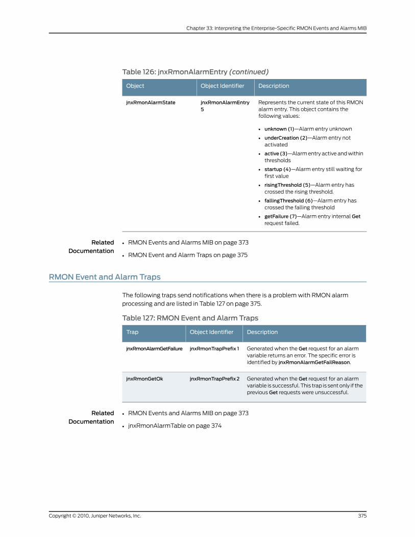
Table 126: jnxRmonAlarmEntry (continued)
DescriptionObject IdentifierObject
Represents the current state of this RMONalarm entry. This object contains thefollowing values:
• unknown (1)—Alarm entry unknown
• underCreation (2)—Alarm entry notactivated
• active (3)—Alarm entry active and withinthresholds
• startup (4)—Alarm entry still waiting forfirst value
• risingThreshold (5)—Alarm entry hascrossed the rising threshold.
• fallingThreshold (6)—Alarm entry hascrossed the falling threshold
• getFailure (7)—Alarm entry internal Getrequest failed.
jnxRmonAlarmEntry5
jnxRmonAlarmState
RelatedDocumentation
RMON Events and Alarms MIB on page 373•
• RMON Event and Alarm Traps on page 375
RMON Event and Alarm Traps
The following traps send notifications when there is a problem with RMON alarm
processing and are listed in Table 127 on page 375.
Table 127: RMON Event and Alarm Traps
DescriptionObject IdentifierTrap
Generated when the Get request for an alarmvariable returns an error. The specific error isidentified by jnxRmonAlarmGetFailReason.
jnxRmonTrapPrefix 1jnxRmonAlarmGetFailure
Generated when the Get request for an alarmvariable is successful. This trap is sent only if theprevious Get requests were unsuccessful.
jnxRmonTrapPrefix2jnxRmonGetOk
RelatedDocumentation
• RMON Events and Alarms MIB on page 373
• jnxRmonAlarmTable on page 374
375Copyright © 2010, Juniper Networks, Inc.
Chapter 33: Interpreting the Enterprise-Specific RMON Events and Alarms MIB

Copyright © 2010, Juniper Networks, Inc.376
SRX100, SRX210, SRX220, SRX240, and SRX650 Services Gateways MIB Reference
CHAPTER 34
Interpreting the Enterprise-SpecificSecurity Interface Extension Objects MIB
• Security Interface Extension Objects MIB on page 377
• jnxJsIfMonTable on page 377
Security Interface Extension Objects MIB
The Juniper Networks enterprise-specific Security Interface Extension Objects MIB,
jnxJsIfMIB, whose object ID is {jnxJsIf 1}, defines the object that are used to monitor the
entries in the interfaces that pertain to the security management of the interface.
For a downloadable version of this MIB, see
http://www.juniper.net/techpubs/en_US/junos10.4/topics/reference/mibs/mib-jnx-js-if-ext.txt
.
For information about the enterprise-specific Security Interface Extension Objects MIB
objects, see the following topic:
• jnxJsIfMonTable on page 377
RelatedDocumentation
Juniper Networks Enterprise-Specific MIBs on page 23•
• Standard SNMP MIBs Supported by Junos OS on page 12
jnxJsIfMonTable
jnxJsIfMonTable, whose object ID is {jnxJsIfExtension 1}, extends the interface entries on
a particular interface to support the security related-objects listed in Table 128 on page 378.
The table is indexed by ifIndex.
377Copyright © 2010, Juniper Networks, Inc.
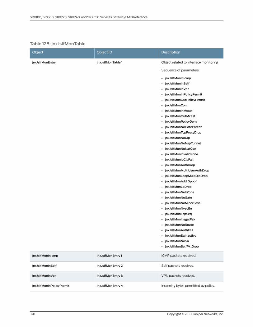
Table 128: jnxJsIfMonTable
DescriptionObject IDObject
Object related to interface monitoring
Sequence of parameters:
• jnxJsIfMonInIcmp
• jnxJsIfMonInSelf
• jnxJsIfMonInVpn
• jnxJsIfMonInPolicyPermit
• jnxJsIfMonOutPolicyPermit
• jnxJsIfMonConn
• jnxJsIfMonInMcast
• jnxJsIfMonOutMcast
• jnxJsIfMonPolicyDeny
• jnxJsIfMonNoGateParent
• jnxJsIfMonTcpProxyDrop
• jnxJsIfMonNoDip
• jnxJsIfMonNoNspTunnel
• jnxJsIfMonNoNatCon
• jnxJsIfMonInvalidZone
• jnxJsIfMonIpClsFail
• jnxJsIfMonAuthDrop
• jnxJsIfMonMultiUserAuthDrop
• jnxJsIfMonLoopMultiDipDrop
• jnxJsIfMonAddrSpoof
• jnxJsIfMonLpDrop
• jnxJsIfMonNullZone
• jnxJsIfMonNoGate
• jnxJsIfMonNoMinorSess
• jnxJsIfMonNvecErr
• jnxJsIfMonTcpSeq
• jnxJsIfMonIllegalPak
• jnxJsIfMonNoRoute
• jnxJsIfMonAuthFail
• jnxJsIfMonSaInactive
• jnxJsIfMonNoSa
• jnxJsIfMonSelfPktDrop
jnxJsIfMonTable 1jnxJsIfMonEntry
ICMP packets received.jnxJsIfMonEntry 1jnxJsIfMonInIcmp
Self packets received.jnxJsIfMonEntry 2jnxJsIfMonInSelf
VPN packets received.jnxJsIfMonEntry 3jnxJsIfMonInVpn
Incoming bytes permitted by policy.jnxJsIfMonEntry 4jnxJsIfMonInPolicyPermit
Copyright © 2010, Juniper Networks, Inc.378
SRX100, SRX210, SRX220, SRX240, and SRX650 Services Gateways MIB Reference
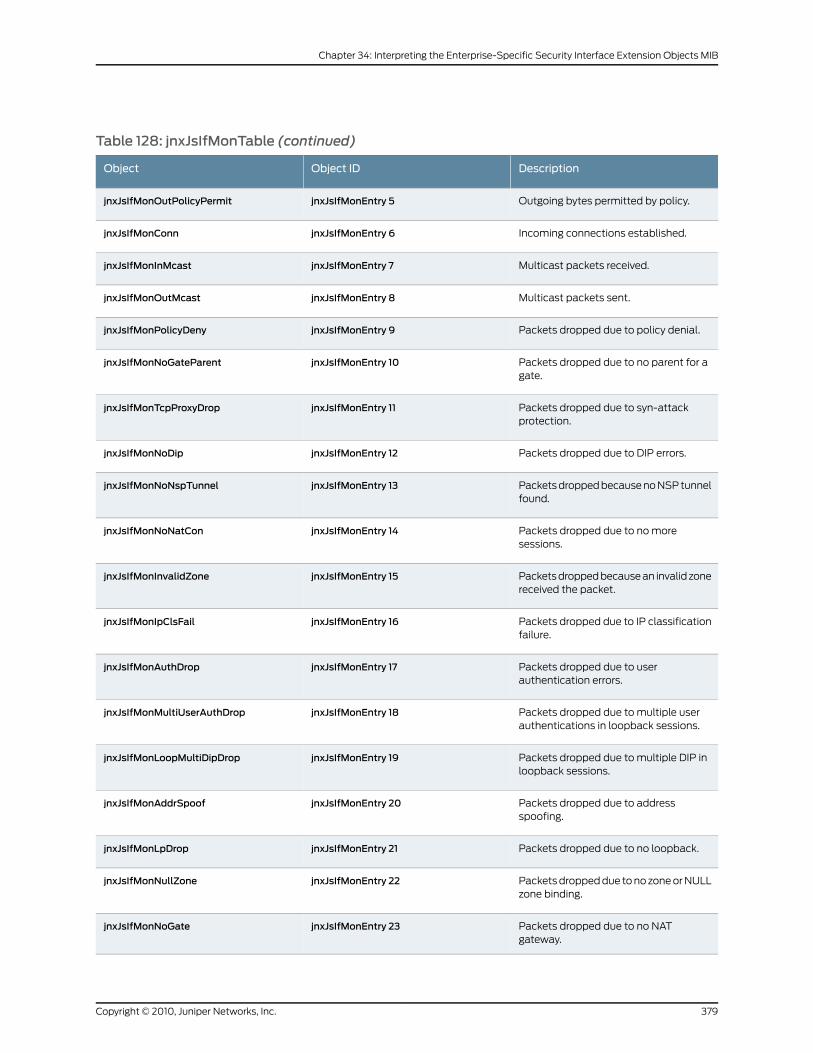
Table 128: jnxJsIfMonTable (continued)
DescriptionObject IDObject
Outgoing bytes permitted by policy.jnxJsIfMonEntry 5jnxJsIfMonOutPolicyPermit
Incoming connections established.jnxJsIfMonEntry 6jnxJsIfMonConn
Multicast packets received.jnxJsIfMonEntry 7jnxJsIfMonInMcast
Multicast packets sent.jnxJsIfMonEntry 8jnxJsIfMonOutMcast
Packets dropped due to policy denial.jnxJsIfMonEntry 9jnxJsIfMonPolicyDeny
Packets dropped due to no parent for agate.
jnxJsIfMonEntry 10jnxJsIfMonNoGateParent
Packets dropped due to syn-attackprotection.
jnxJsIfMonEntry 11jnxJsIfMonTcpProxyDrop
Packets dropped due to DIP errors.jnxJsIfMonEntry 12jnxJsIfMonNoDip
Packets dropped because no NSP tunnelfound.
jnxJsIfMonEntry 13jnxJsIfMonNoNspTunnel
Packets dropped due to no moresessions.
jnxJsIfMonEntry 14jnxJsIfMonNoNatCon
Packets dropped because an invalid zonereceived the packet.
jnxJsIfMonEntry 15jnxJsIfMonInvalidZone
Packets dropped due to IP classificationfailure.
jnxJsIfMonEntry 16jnxJsIfMonIpClsFail
Packets dropped due to userauthentication errors.
jnxJsIfMonEntry 17jnxJsIfMonAuthDrop
Packets dropped due to multiple userauthentications in loopback sessions.
jnxJsIfMonEntry 18jnxJsIfMonMultiUserAuthDrop
Packets dropped due to multiple DIP inloopback sessions.
jnxJsIfMonEntry 19jnxJsIfMonLoopMultiDipDrop
Packets dropped due to addressspoofing.
jnxJsIfMonEntry 20jnxJsIfMonAddrSpoof
Packets dropped due to no loopback.jnxJsIfMonEntry 21jnxJsIfMonLpDrop
Packets dropped due to no zone or NULLzone binding.
jnxJsIfMonEntry 22jnxJsIfMonNullZone
Packets dropped due to no NATgateway.
jnxJsIfMonEntry 23jnxJsIfMonNoGate
379Copyright © 2010, Juniper Networks, Inc.
Chapter 34: Interpreting the Enterprise-Specific Security Interface Extension Objects MIB
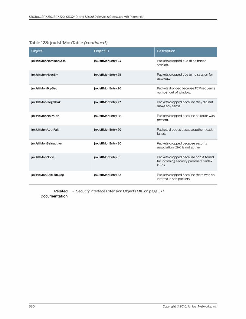
Table 128: jnxJsIfMonTable (continued)
DescriptionObject IDObject
Packets dropped due to no minorsession.
jnxJsIfMonEntry 24jnxJsIfMonNoMinorSess
Packets dropped due to no session forgateway.
jnxJsIfMonEntry 25jnxJsIfMonNvecErr
Packets dropped because TCP sequencenumber out of window.
jnxJsIfMonEntry 26jnxJsIfMonTcpSeq
Packets dropped because they did notmake any sense.
jnxJsIfMonEntry 27jnxJsIfMonIllegalPak
Packets dropped because no route waspresent.
jnxJsIfMonEntry 28jnxJsIfMonNoRoute
Packets dropped because authenticationfailed.
jnxJsIfMonEntry 29jnxJsIfMonAuthFail
Packets dropped because securityassociation (SA) is not active.
jnxJsIfMonEntry 30jnxJsIfMonSaInactive
Packets dropped because no SA foundfor incoming security parameter index(SPI).
jnxJsIfMonEntry 31jnxJsIfMonNoSa
Packets dropped because there was nointerest in self packets.
jnxJsIfMonEntry 32jnxJsIfMonSelfPktDrop
RelatedDocumentation
• Security Interface Extension Objects MIB on page 377
Copyright © 2010, Juniper Networks, Inc.380
SRX100, SRX210, SRX220, SRX240, and SRX650 Services Gateways MIB Reference
CHAPTER 35
Interpreting the Enterprise-Specific SIPCommon MIB
• SIP Common MIB Overview on page 381
• Common Configuration Objects on page 382
• Support for Multiple Ports on page 382
• Support for SIP Option Tags on page 383
• Supported SIP Methods on page 383
• SIP Timer Configuration on page 384
SIP CommonMIB Overview
The Juniper Networks enterprise-specific Session Initiation Protocol (SIP) common MIB,
whose object identifier is { jnxSip 1 }, defines objects that are common to all SIP entities.
For a downloadable version of the SIP common MIB, see
http://www.juniper.net/techpubs/en_US/junos10.4/
topics/reference/mibs/mib-jnx-sipcommon.txt .
For more information about the enterprise-specific SIP common MIBs, see the following
topics:
• Common Configuration Objects on page 382
• Support for Multiple Ports on page 382
• Support for SIP Option Tags on page 383
• Supported SIP Methods on page 383
• SIP Timer Configuration on page 384
RelatedDocumentation
Juniper Networks Enterprise-Specific MIBs on page 23•
• Standard SNMP MIBs Supported by Junos OS on page 12
381Copyright © 2010, Juniper Networks, Inc.
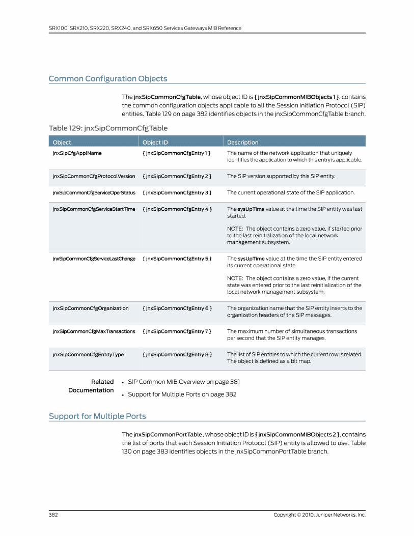
Common Configuration Objects
The jnxSipCommonCfgTable, whose object ID is { jnxSipCommonMIBObjects 1 }, contains
the common configuration objects applicable to all the Session Initiation Protocol (SIP)
entities. Table 129 on page 382 identifies objects in the jnxSipCommonCfgTable branch.
Table 129: jnxSipCommonCfgTable
DescriptionObject IDObject
The name of the network application that uniquelyidentifies the application to which this entry is applicable.
{ jnxSipCommonCfgEntry 1 }jnxSipCfgApplName
The SIP version supported by this SIP entity.{ jnxSipCommonCfgEntry 2 }jnxSipCommonCfgProtocolVersion
The current operational state of the SIP application.{ jnxSipCommonCfgEntry 3 }jnxSipCommonCfgServiceOperStatus
The sysUpTime value at the time the SIP entity was laststarted.
NOTE: The object contains a zero value, if started priorto the last reinitialization of the local networkmanagement subsystem.
{ jnxSipCommonCfgEntry 4 }jnxSipCommonCfgServiceStartTime
The sysUpTime value at the time the SIP entity enteredits current operational state.
NOTE: The object contains a zero value, if the currentstate was entered prior to the last reinitialization of thelocal network management subsystem.
{ jnxSipCommonCfgEntry 5 }jnxSipCommonCfgServiceLastChange
The organization name that the SIP entity inserts to theorganization headers of the SIP messages.
{ jnxSipCommonCfgEntry 6 }jnxSipCommonCfgOrganization
The maximum number of simultaneous transactionsper second that the SIP entity manages.
{ jnxSipCommonCfgEntry 7 }jnxSipCommonCfgMaxTransactions
The list of SIP entities to which the current row is related.The object is defined as a bit map.
{ jnxSipCommonCfgEntry 8 }jnxSipCommonCfgEntityType
RelatedDocumentation
SIP Common MIB Overview on page 381•
• Support for Multiple Ports on page 382
Support for Multiple Ports
The jnxSipCommonPortTable , whose object ID is { jnxSipCommonMIBObjects2}, contains
the list of ports that each Session Initiation Protocol (SIP) entity is allowed to use. Table
130 on page 383 identifies objects in the jnxSipCommonPortTable branch.
Copyright © 2010, Juniper Networks, Inc.382
SRX100, SRX210, SRX220, SRX240, and SRX650 Services Gateways MIB Reference
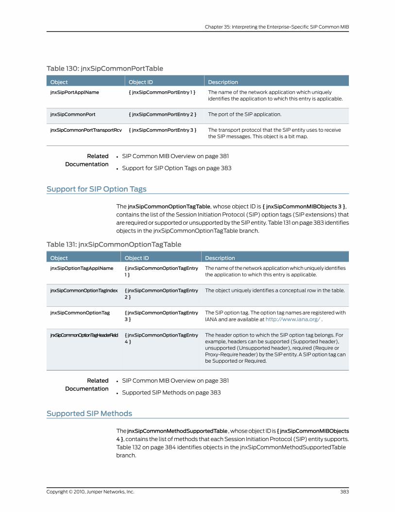
Table 130: jnxSipCommonPortTable
DescriptionObject IDObject
The name of the network application which uniquelyidentifies the application to which this entry is applicable.
{ jnxSipCommonPortEntry 1 }jnxSipPortApplName
The port of the SIP application.{ jnxSipCommonPortEntry 2 }jnxSipCommonPort
The transport protocol that the SIP entity uses to receivethe SIP messages. This object is a bit map.
{ jnxSipCommonPortEntry 3 }jnxSipCommonPortTransportRcv
RelatedDocumentation
SIP Common MIB Overview on page 381•
• Support for SIP Option Tags on page 383
Support for SIP Option Tags
The jnxSipCommonOptionTagTable, whose object ID is { jnxSipCommonMIBObjects 3 },
contains the list of the Session Initiation Protocol (SIP) option tags (SIP extensions) that
are required or supported or unsupported by the SIP entity. Table 131 on page 383 identifies
objects in the jnxSipCommonOptionTagTable branch.
Table 131: jnxSipCommonOptionTagTable
DescriptionObject IDObject
The name of the network application which uniquely identifiesthe application to which this entry is applicable.
{ jnxSipCommonOptionTagEntry1 }
jnxSipOptionTagApplName
The object uniquely identifies a conceptual row in the table.{ jnxSipCommonOptionTagEntry2 }
jnxSipCommonOptionTagIndex
The SIP option tag. The option tag names are registered withIANA and are available at http://www.iana.org/ .
{ jnxSipCommonOptionTagEntry3 }
jnxSipCommonOptionTag
The header option to which the SIP option tag belongs. Forexample, headers can be supported (Supported header),unsupported (Unsupported header), required (Require orProxy-Require header) by the SIP entity. A SIP option tag canbe Supported or Required.
{ jnxSipCommonOptionTagEntry4 }
jnxSipCommonOptionTagHeaderField
RelatedDocumentation
SIP Common MIB Overview on page 381•
• Supported SIP Methods on page 383
Supported SIPMethods
The jnxSipCommonMethodSupportedTable , whose object ID is{ jnxSipCommonMIBObjects
4}, contains the list of methods that each Session Initiation Protocol (SIP) entity supports.
Table 132 on page 384 identifies objects in the jnxSipCommonMethodSupportedTable
branch.
383Copyright © 2010, Juniper Networks, Inc.
Chapter 35: Interpreting the Enterprise-Specific SIP Common MIB
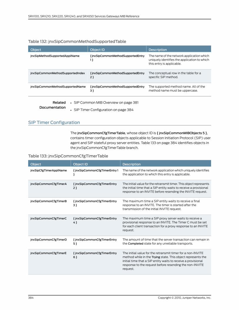
Table 132: jnxSipCommonMethodSupportedTable
DescriptionObject IDObject
The name of the network application whichuniquely identifies the application to whichthis entry is applicable.
{jnxSipCommonMethodSupportedEntry1 }
jnxSipMethodSupportedApplName
The conceptual row in the table for aspecific SIP method.
{jnxSipCommonMethodSupportedEntry2 }
jnxSipCommonMethodSupportedIndex
The supported method name. All of themethod name must be uppercase.
{jnxSipCommonMethodSupportedEntry3 }
jnxSipCommonMethodSupportedName
RelatedDocumentation
SIP Common MIB Overview on page 381•
• SIP Timer Configuration on page 384
SIP Timer Configuration
The jnxSipCommonCfgTimerTable, whose object ID is { jnxSipCommonMIBObjects 5 },
contains timer configuration objects applicable to Session Initiation Protocol (SIP) user
agent and SIP stateful proxy server entities. Table 133 on page 384 identifies objects in
the jnxSipCommonCfgTimerTable branch.
Table 133: jnxSipCommonCfgTimerTable
DescriptionObject IDObject
The name of the network application which uniquely identifiesthe application to which this entry is applicable.
{ jnxSipCommonCfgTimerEntry 1}
jnxSipCfgTimerApplName
The initial value for the retransmit timer. This object representsthe initial time that a SIP entity waits to receive a provisionalresponse to an INVITE before resending the INVITE request.
{ jnxSipCommonCfgTimerEntry2 }
jnxSipCommonCfgTimerA
The maximum time a SIP entity waits to receive a finalresponse to an INVITE. The timer is started after thetransmission of the initial INVITE request.
{ jnxSipCommonCfgTimerEntry3 }
jnxSipCommonCfgTimerB
The maximum time a SIP proxy server waits to receive aprovisional response to an INVITE. The Timer C must be setfor each client transaction for a proxy response to an INVITErequest.
{ jnxSipCommonCfgTimerEntry4 }
jnxSipCommonCfgTimerC
The amount of time that the server transaction can remain inthe Completed state for any unreliable transports.
{ jnxSipCommonCfgTimerEntry5 }
jnxSipCommonCfgTimerD
The initial value for the retransmit timer for a non-INVITEmethod while in the Trying state. This object represents theinitial time that a SIP entity waits to receive a provisionalresponse to the request before resending the non-INVITErequest.
{ jnxSipCommonCfgTimerEntry6 }
jnxSipCommonCfgTimerE
Copyright © 2010, Juniper Networks, Inc.384
SRX100, SRX210, SRX220, SRX240, and SRX650 Services Gateways MIB Reference
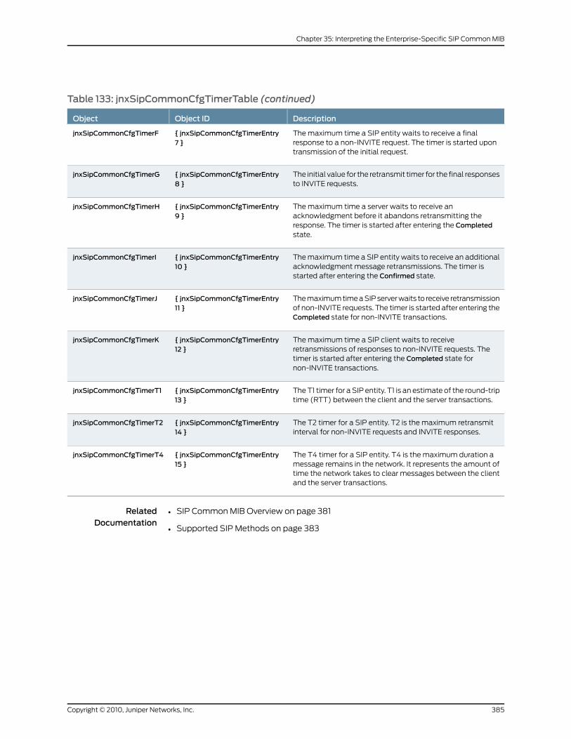
Table 133: jnxSipCommonCfgTimerTable (continued)
DescriptionObject IDObject
The maximum time a SIP entity waits to receive a finalresponse to a non-INVITE request. The timer is started upontransmission of the initial request.
{ jnxSipCommonCfgTimerEntry7 }
jnxSipCommonCfgTimerF
The initial value for the retransmit timer for the final responsesto INVITE requests.
{ jnxSipCommonCfgTimerEntry8 }
jnxSipCommonCfgTimerG
The maximum time a server waits to receive anacknowledgment before it abandons retransmitting theresponse. The timer is started after entering the Completedstate.
{ jnxSipCommonCfgTimerEntry9 }
jnxSipCommonCfgTimerH
The maximum time a SIP entity waits to receive an additionalacknowledgment message retransmissions. The timer isstarted after entering the Confirmed state.
{ jnxSipCommonCfgTimerEntry10 }
jnxSipCommonCfgTimerI
The maximum time a SIP server waits to receive retransmissionof non-INVITE requests. The timer is started after entering theCompleted state for non-INVITE transactions.
{ jnxSipCommonCfgTimerEntry11 }
jnxSipCommonCfgTimerJ
The maximum time a SIP client waits to receiveretransmissions of responses to non-INVITE requests. Thetimer is started after entering the Completed state fornon-INVITE transactions.
{ jnxSipCommonCfgTimerEntry12 }
jnxSipCommonCfgTimerK
The T1 timer for a SIP entity. T1 is an estimate of the round-triptime (RTT) between the client and the server transactions.
{ jnxSipCommonCfgTimerEntry13 }
jnxSipCommonCfgTimerT1
The T2 timer for a SIP entity. T2 is the maximum retransmitinterval for non-INVITE requests and INVITE responses.
{ jnxSipCommonCfgTimerEntry14 }
jnxSipCommonCfgTimerT2
The T4 timer for a SIP entity. T4 is the maximum duration amessage remains in the network. It represents the amount oftime the network takes to clear messages between the clientand the server transactions.
{ jnxSipCommonCfgTimerEntry15 }
jnxSipCommonCfgTimerT4
RelatedDocumentation
• SIP Common MIB Overview on page 381
• Supported SIP Methods on page 383
385Copyright © 2010, Juniper Networks, Inc.
Chapter 35: Interpreting the Enterprise-Specific SIP Common MIB

Copyright © 2010, Juniper Networks, Inc.386
SRX100, SRX210, SRX220, SRX240, and SRX650 Services Gateways MIB Reference
CHAPTER 36
Interpreting theEnterprise-Specific SNMPIDP MIB
• IDP MIB on page 387
• jnxJsIdpAttackTable on page 387
• IDP Signature Update and Attack Traps on page 388
IDPMIB
The Juniper Networks enterprise-specific IDP MIB, jnxJsIdpMIB, whose object ID is
{jnxJsIdpRoot 1}, extends SNMP support to the following features on Juniper Networks
SRX100, SRX210, SRX220, SRX240, and SRX650 Services Gateways:
• Key monitoring and threshold-crossing traps
• Attack-related monitoring and traps
• IDP database update status and traps
For a downloadable version of this MIB, see
http://www.juniper.net/techpubs/en_US/junos10.4/topics/reference/mibs/mib-jnx-js-idp.txt
.
For information about the enterprise-specific IDP MIB objects, see the following topics:
• jnxJsIdpObjects
• jnxJsIdpAttackTable on page 387
• IDP Signature Update and Attack Traps on page 388
RelatedDocumentation
Juniper Networks Enterprise-Specific MIBs on page 23•
• Standard SNMP MIBs Supported by Junos OS on page 12
jnxJsIdpAttackTable
The jnxJsIdpAttackTable, whose object ID is {jnxJsIdpObjects 7}, contains the details of
each attack and the number of hits involved. The objects are listed in Table 134 on page 388.
387Copyright © 2010, Juniper Networks, Inc.
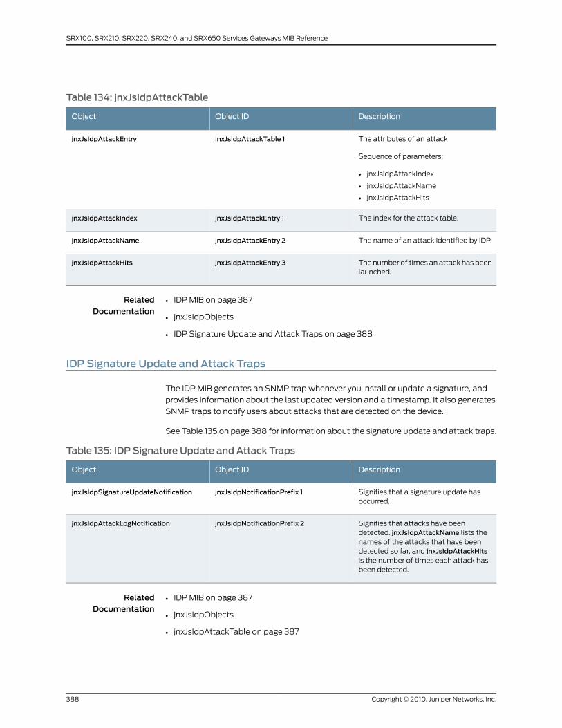
Table 134: jnxJsIdpAttackTable
DescriptionObject IDObject
The attributes of an attack
Sequence of parameters:
• jnxJsIdpAttackIndex
• jnxJsIdpAttackName
• jnxJsIdpAttackHits
jnxJsIdpAttackTable 1jnxJsIdpAttackEntry
The index for the attack table.jnxJsIdpAttackEntry 1jnxJsIdpAttackIndex
The name of an attack identified by IDP.jnxJsIdpAttackEntry 2jnxJsIdpAttackName
The number of times an attack has beenlaunched.
jnxJsIdpAttackEntry 3jnxJsIdpAttackHits
RelatedDocumentation
IDP MIB on page 387•
• jnxJsIdpObjects
• IDP Signature Update and Attack Traps on page 388
IDP Signature Update and Attack Traps
The IDP MIB generates an SNMP trap whenever you install or update a signature, and
provides information about the last updated version and a timestamp. It also generates
SNMP traps to notify users about attacks that are detected on the device.
See Table 135 on page 388 for information about the signature update and attack traps.
Table 135: IDP Signature Update and Attack Traps
DescriptionObject IDObject
Signifies that a signature update hasoccurred.
jnxJsIdpNotificationPrefix 1jnxJsIdpSignatureUpdateNotification
Signifies that attacks have beendetected. jnxJsIdpAttackName lists thenames of the attacks that have beendetected so far, and jnxJsIdpAttackHitsis the number of times each attack hasbeen detected.
jnxJsIdpNotificationPrefix 2jnxJsIdpAttackLogNotification
RelatedDocumentation
• IDP MIB on page 387
• jnxJsIdpObjects
• jnxJsIdpAttackTable on page 387
Copyright © 2010, Juniper Networks, Inc.388
SRX100, SRX210, SRX220, SRX240, and SRX650 Services Gateways MIB Reference
CHAPTER 37
Interpreting the Enterprise-SpecificSystem Log MIB
• System Log MIB on page 389
• jnxSyslogTable on page 390
• jnxSyslogAvTable on page 392
System LogMIB
Event policies can include an action that raises traps for events based on system log
messages. This feature enables notification of an SNMP trap-based application when
an important system log message occurs. You can convert any system log message (for
which there are no corresponding traps) into a trap. This feature is valuable for customers
who use network management system traps rather than system log messages to monitor
their networks. For more information about converting system log messages into traps,
see the Junos Configuration and Operations Automation Guide.
The Juniper Networks enterprise-specific System Log MIB, whose object identifier is
{jnxMibs 35}, provides support for this feature.
For a downloadable version of this MIB, see
http://www.juniper.net/techpubs/en_US/junos10.4/topics/reference/mibs/mib-jnx-syslog.txt
.
For information about the enterprise-specific System Log MIB objects, see the following
topics:
• jnxSyslogTable on page 390
• jnxSyslogAvTable on page 392
RelatedDocumentation
Juniper Networks Enterprise-Specific MIBs on page 23•
• Standard SNMP MIBs Supported by Junos OS on page 12
389Copyright © 2010, Juniper Networks, Inc.
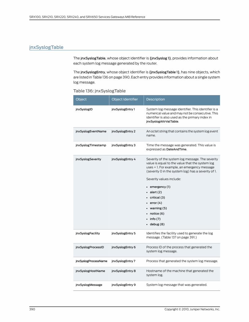
jnxSyslogTable
The jnxSyslogTable, whose object identifier is {jnxSyslog 1}, provides information about
each system log message generated by the router.
The jnxSyslogEntry, whose object identifier is {jnxSyslogTable 1}, has nine objects, which
are listed in Table 136 on page 390. Each entry provides information about a single system
log message.
Table 136: jnxSyslogTable
DescriptionObject IdentifierObject
System log message identifier. This identifier is anumerical value and may not be consecutive. Thisidentifier is also used as the primary index injnxSyslogAttrValTable.
jnxSyslogEntry 1jnxSyslogID
An octet string that contains the system log eventname.
jnxSyslogEntry 2jnxSyslogEventName
Time the message was generated. This value isexpressed as DateAndTime.
jnxSyslogEntry 3jnxSyslogTimestamp
Severity of the system log message. The severityvalue is equal to the value that the system loguses + 1. For example, an emergency message(severity 0 in the system log) has a severity of 1.
Severity values include:
• emergency (1)
• alert (2)
• critical (3)
• error (4)
• warning (5)
• notice (6)
• info (7)
• debug (8)
jnxSyslogEntry 4jnxSyslogSeverity
Identifies the facility used to generate the logmessage. (Table 137 on page 391.)
jnxSyslogEntry 5jnxSyslogFacility
Process ID of the process that generated thesystem log message.
jnxSyslogEntry 6jnxSyslogProcessID
Process that generated the system log message.jnxSyslogEntry 7jnxSyslogProcessName
Hostname of the machine that generated thesystem log.
jnxSyslogEntry 8jnxSyslogHostName
System log message that was generated.jnxSyslogEntry 9jnxSyslogMessage
Copyright © 2010, Juniper Networks, Inc.390
SRX100, SRX210, SRX220, SRX240, and SRX650 Services Gateways MIB Reference
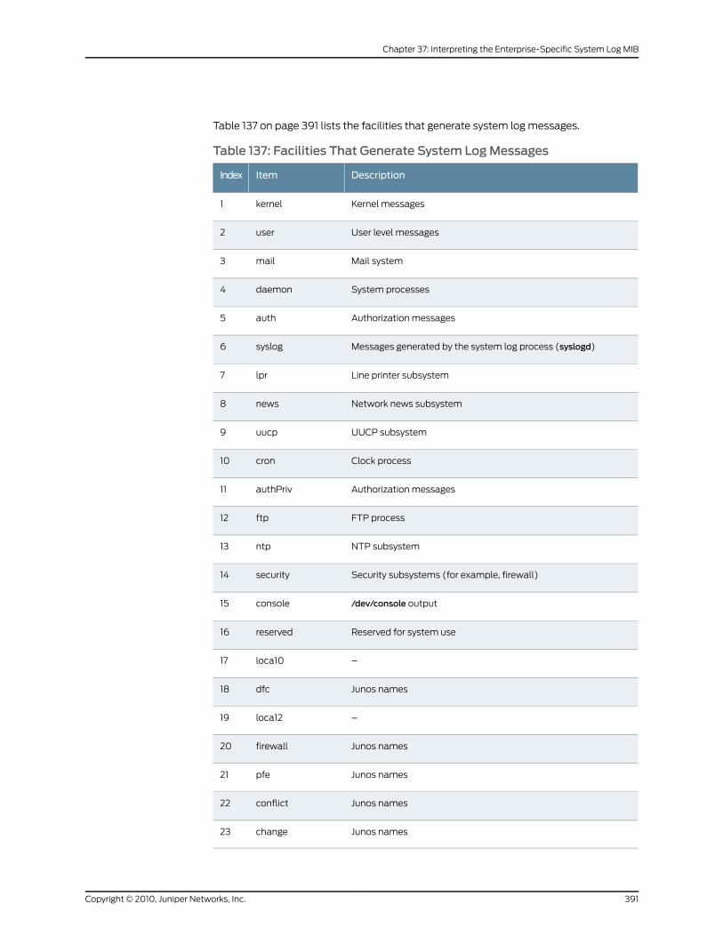
Table 137 on page 391 lists the facilities that generate system log messages.
Table 137: Facilities That Generate System LogMessages
DescriptionItemIndex
Kernel messageskernel1
User level messagesuser2
Mail systemmail3
System processesdaemon4
Authorization messagesauth5
Messages generated by the system log process (syslogd)syslog6
Line printer subsystemlpr7
Network news subsystemnews8
UUCP subsystemuucp9
Clock processcron10
Authorization messagesauthPriv11
FTP processftp12
NTP subsystemntp13
Security subsystems (for example, firewall)security14
/dev/console outputconsole15
Reserved for system usereserved16
–loca1017
Junos namesdfc18
–loca1219
Junos namesfirewall20
Junos namespfe21
Junos namesconflict22
Junos nameschange23
391Copyright © 2010, Juniper Networks, Inc.
Chapter 37: Interpreting the Enterprise-Specific System Log MIB
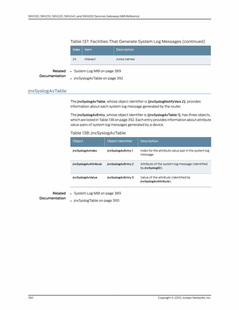
Table 137: Facilities That Generate System LogMessages (continued)
DescriptionItemIndex
Junos namesinteract24
RelatedDocumentation
System Log MIB on page 389•
• jnxSyslogAvTable on page 392
jnxSyslogAvTable
The jnxSyslogAvTable, whose object identifier is {jnxSyslogNotifyVars 2}, provides
information about each system log message generated by the router.
The jnxSyslogAvEntry, whose object identifier is {jnxSyslogAvTable 1}, has three objects,
which are listed in Table 138 on page 392. Each entry provides information about attribute
value pairs of system log messages generated by a device.
Table 138: jnxSyslogAvTable
DescriptionObject IdentifierObject
Index for the attribute value pair in the system logmessage.
jnxSyslogAvEntry 1jnxSyslogAvIndex
Attribute of the system log message (identifiedby jnxSyslogID).
jnxSyslogAvEntry 2jnxSyslogAvAttribute
Value of the attribute (identified byjnxSyslogAvAttribute).
jnxSyslogAvEntry 3jnxSyslogAvValue
RelatedDocumentation
• System Log MIB on page 389
• jnxSyslogTable on page 390
Copyright © 2010, Juniper Networks, Inc.392
SRX100, SRX210, SRX220, SRX240, and SRX650 Services Gateways MIB Reference
CHAPTER 38
Interpreting the Enterprise-SpecificTraceroute MIB
This chapter contains the following topics:
• Traceroute MIB on page 393
• jnxTraceRouteCtlTable on page 393
TracerouteMIB
The Juniper Networks enterprise-specific Traceroute MIB supports Junos OS extensions
of traceroutes and remote operations. Items in this MIB are created when entries are
created in the traceRouteCtlTable of the Traceroute MIB. Each item is indexed exactly
the same way as it is in the enterprise-specific Traceroute MIB. For a downloadable
version of the Traceroute MIB, see
http://www.juniper.net/techpubs/en_US/junos10.4/topics/reference/mibs/mib-jnx-traceroute.txt
.
For more information about using the Traceroute MIB and enterprise-specific Traceroute
MIB, see the Junos OS Network Management Configuration Guide.
For information about the enterprise-specific Traceroute MIB objects, see the following
topic:
• jnxTraceRouteCtlTable on page 393
RelatedDocumentation
Juniper Networks Enterprise-Specific MIBs on page 23•
• Standard SNMP MIBs Supported by Junos OS on page 12
jnxTraceRouteCtlTable
The jnxTraceRouteCtlTable, whose object identifier is {jnxTraceRouteObjects 2}, defines
the jnxTraceRoute control table for providing enterprise-specific options to the
corresponding traceRouteCtlEntry.
393Copyright © 2010, Juniper Networks, Inc.
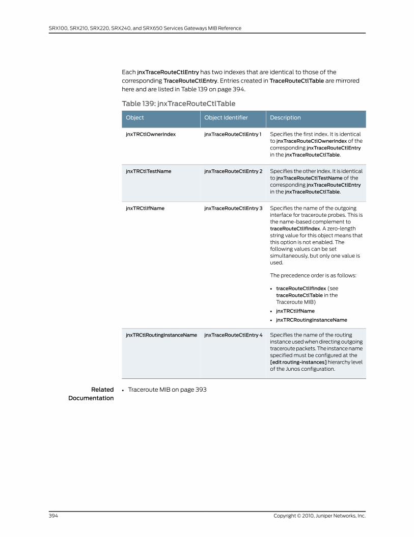
Each jnxTraceRouteCtlEntry has two indexes that are identical to those of the
corresponding TraceRouteCtlEntry. Entries created in TraceRouteCtlTable are mirrored
here and are listed in Table 139 on page 394.
Table 139: jnxTraceRouteCtlTable
DescriptionObject IdentifierObject
Specifies the first index. It is identicalto jnxTraceRouteCtlOwnerIndex of thecorresponding jnxTraceRouteCtlEntryin the jnxTraceRouteCtlTable.
jnxTraceRouteCtlEntry 1jnxTRCtlOwnerIndex
Specifies the other index. It is identicalto jnxTraceRouteCtlTestName of thecorresponding jnxTraceRouteCtlEntryin the jnxTraceRouteCtlTable.
jnxTraceRouteCtlEntry 2jnxTRCtlTestName
Specifies the name of the outgoinginterface for traceroute probes. This isthe name-based complement totraceRouteCtlIfIndex. A zero-lengthstring value for this object means thatthis option is not enabled. Thefollowing values can be setsimultaneously, but only one value isused.
The precedence order is as follows:
• traceRouteCtlIfIndex (seetraceRouteCtlTable in theTraceroute MIB)
• jnxTRCtlIfName
• jnxTRCRoutingInstanceName
jnxTraceRouteCtlEntry 3jnxTRCtlIfName
Specifies the name of the routinginstance used when directing outgoingtraceroute packets. The instance namespecified must be configured at the[edit routing-instances]hierarchy levelof the Junos configuration.
jnxTraceRouteCtlEntry 4jnxTRCtlRoutingInstanceName
RelatedDocumentation
• Traceroute MIB on page 393
Copyright © 2010, Juniper Networks, Inc.394
SRX100, SRX210, SRX220, SRX240, and SRX650 Services Gateways MIB Reference
CHAPTER 39
Interpreting the Enterprise-Specific UtilityMIB
• Utility MIB on page 395
• jnxUtilCounter32Table on page 396
• jnxUtilCounter64Table on page 396
• jnxUtilIntegerTable on page 397
• jnxUtilUintTable on page 397
• jnxUtilStringTable on page 398
Utility MIB
The Juniper Networks enterprise-specific Utility MIB, whose object ID is {jnxUtilMibRoot 1}
defines objects for counters, intergers, and strings. The Utility MIB contains one table for
each of the following five data types:
• 32–bit counters
• 64–bit counters
• Signed integers
• Unsigned integers
• Octet strings
Each data has an arbitrary ASCII name, which is defined when the data is populated, and
a timestamp that shows the last time when the data instance was modified. For a
downloadable version of this MIB, see
http://www.juniper.net/techpubs/en_US/junos10.4/topics/reference/mibs/mib-jnx-util.txt
.
For information about the enterprise-specific Utility MIB objects, see the following topics:
• jnxUtilCounter32Table on page 396
• jnxUtilCounter64Table on page 396
• jnxUtilIntegerTable on page 397
395Copyright © 2010, Juniper Networks, Inc.

• jnxUtilUintTable on page 397
• jnxUtilStringTable on page 398
RelatedDocumentation
Juniper Networks Enterprise-Specific MIBs on page 23•
• Standard SNMP MIBs Supported by Junos OS on page 12
jnxUtilCounter32Table
jnxUtilCounter32Table, whose object ID is {jnxUtilData 1},contains information about
32–bit counters.
Each jnxUtilCounter32Entry has the objects listed in Table 140 on page 396.
Table 140: jnxUtilCounter32Entry
DescriptionObject IDObject
Name assigned to the instance.jnxUtilCounter32Entry 1jnxUtilCounter32Name
Value of the instance.jnxUtilCounter32Entry 2jnxUtilCounter32Value
Time when the instance was last populated.jnxUtilCounter32Entry 3jnxUtilCounter32Time
RelatedDocumentation
Utility MIB on page 395•
• jnxUtilCounter64Table on page 396
• jnxUtilIntegerTable on page 397
• jnxUtilUintTable on page 397
• jnxUtilStringTable on page 398
jnxUtilCounter64Table
jnxUtilCounter64Table, whose object ID is {jnxUtilData 2}, contains information about
64–bit counters.
Each jnxUtilCounter64Entry has the objects listed in Table 141 on page 396.
Table 141: jnxUtilCounter64Entry
DescriptionObject IDObject
Name assigned to the instance.jnxUtilCounter64Entry 1jnxUtilCounter64Name
Value of the instance.jnxUtilCounter64Entry 2jnxUtilCounter64Value
Time when the instance was last populated.jnxUtilCounter64Entry 3jnxUtilCounter64Time
Copyright © 2010, Juniper Networks, Inc.396
SRX100, SRX210, SRX220, SRX240, and SRX650 Services Gateways MIB Reference
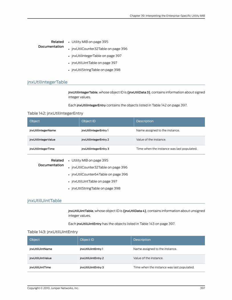
RelatedDocumentation
Utility MIB on page 395•
• jnxUtilCounter32Table on page 396
• jnxUtilIntegerTable on page 397
• jnxUtilUintTable on page 397
• jnxUtilStringTable on page 398
jnxUtilIntegerTable
jnxUtilIntegerTable, whose object ID is {jnxUtilData3}, contains information about signed
integer values.
Each jnxUtilIntegerEntry contains the objects listed in Table 142 on page 397.
Table 142: jnxUtilIntegerEntry
DescriptionObject IDObject
Name assigned to the instance.jnxUtilIntegerEntry 1jnxUtilIntegerName
Value of the instance.jnxUtilIntegerEntry 2jnxUtilIntegerValue
Time when the instance was last populated.jnxUtilIntegerEntry 3jnxUtilIntegerTime
RelatedDocumentation
Utility MIB on page 395•
• jnxUtilCounter32Table on page 396
• jnxUtilCounter64Table on page 396
• jnxUtilUintTable on page 397
• jnxUtilStringTable on page 398
jnxUtilUintTable
jnxUtilUintTable, whose object ID is {jnxUtilData4}, contains information about unsigned
integer values.
Each jnxUtilUintEntry has the objects listed in Table 143 on page 397.
Table 143: jnxUtilUintEntry
DescriptionObject IDObject
Name assigned to the instance.jnxUtilUintEntry 1jnxUtilUintName
Value of the instance.jnxUtilUintEntry 2jnxUtilUintValue
Time when the instance was last populated.jnxUtilUintEntry 3jnxUtilUintTime
397Copyright © 2010, Juniper Networks, Inc.
Chapter 39: Interpreting the Enterprise-Specific Utility MIB
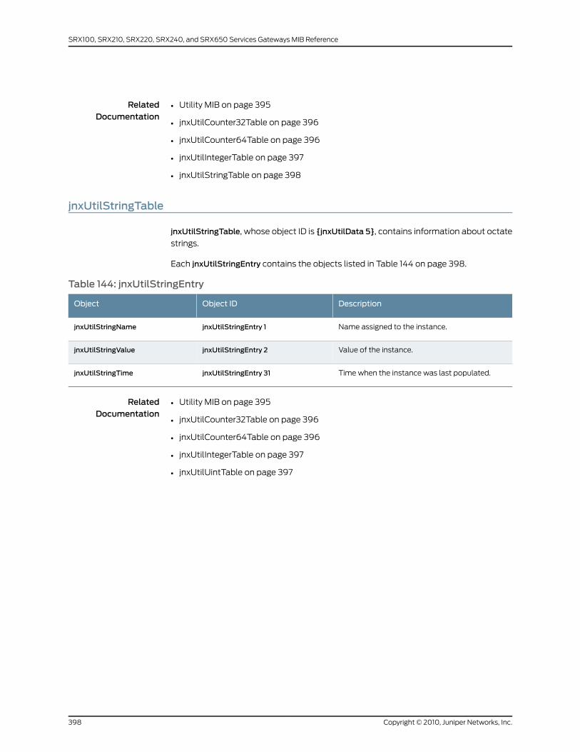
RelatedDocumentation
Utility MIB on page 395•
• jnxUtilCounter32Table on page 396
• jnxUtilCounter64Table on page 396
• jnxUtilIntegerTable on page 397
• jnxUtilStringTable on page 398
jnxUtilStringTable
jnxUtilStringTable, whose object ID is {jnxUtilData 5}, contains information about octate
strings.
Each jnxUtilStringEntry contains the objects listed in Table 144 on page 398.
Table 144: jnxUtilStringEntry
DescriptionObject IDObject
Name assigned to the instance.jnxUtilStringEntry 1jnxUtilStringName
Value of the instance.jnxUtilStringEntry 2jnxUtilStringValue
Time when the instance was last populated.jnxUtilStringEntry 31jnxUtilStringTime
RelatedDocumentation
• Utility MIB on page 395
• jnxUtilCounter32Table on page 396
• jnxUtilCounter64Table on page 396
• jnxUtilIntegerTable on page 397
• jnxUtilUintTable on page 397
Copyright © 2010, Juniper Networks, Inc.398
SRX100, SRX210, SRX220, SRX240, and SRX650 Services Gateways MIB Reference
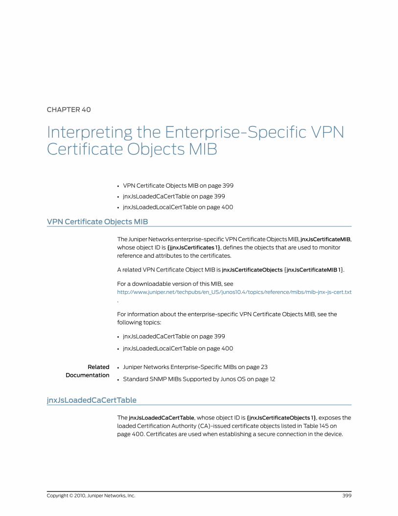
CHAPTER 40
Interpreting the Enterprise-Specific VPNCertificate Objects MIB
• VPN Certificate Objects MIB on page 399
• jnxJsLoadedCaCertTable on page 399
• jnxJsLoadedLocalCertTable on page 400
VPNCertificate Objects MIB
The Juniper Networks enterprise-specific VPN Certificate Objects MIB, jnxJsCertificateMIB,
whose object ID is {jjnxJsCertificates 1}, defines the objects that are used to monitor
reference and attributes to the certificates.
A related VPN Certificate Object MIB is jnxJsCertificateObjects {jnxJsCertificateMIB 1}.
For a downloadable version of this MIB, see
http://www.juniper.net/techpubs/en_US/junos10.4/topics/reference/mibs/mib-jnx-js-cert.txt
.
For information about the enterprise-specific VPN Certificate Objects MIB, see the
following topics:
• jnxJsLoadedCaCertTable on page 399
• jnxJsLoadedLocalCertTable on page 400
RelatedDocumentation
Juniper Networks Enterprise-Specific MIBs on page 23•
• Standard SNMP MIBs Supported by Junos OS on page 12
jnxJsLoadedCaCertTable
The jnxJsLoadedCaCertTable, whose object ID is {jnxJsCertificateObjects 1}, exposes the
loaded Certification Authority (CA)-issued certificate objects listed in Table 145 on
page 400. Certificates are used when establishing a secure connection in the device.
399Copyright © 2010, Juniper Networks, Inc.

Table 145: jnxJsLoadedCaCertTable
DescriptionObject IDObject
Loaded CA certificate entry. The loaded CA certificate entryis indexed by the CA certification name.
Sequence of parameters:
• jnxJsLoadedCaCertName
• jnxJsLoadedCaCertSubject
• jnxJsLoadedCaCertExpire
• jnxJsLoadedCaCertIssuer
jnxJsLoadedCaCertTable 1jnxJsLoadedCaCertEntry
Loaded CA certificate name. This name is unique withinthe loaded CA certifcates.
jnxJsLoadedCaCertEntry 1jnxJsLoadedCaCertName
CA certificate subjectjnxJsLoadedCaCertEntry 2jnxJsLoadedCaCertSubject
Expiration time and date of CA certificatejnxJsLoadedCaCertEntry 3jnxJsLoadedCaCertExpire
Issuer of CA certificatejnxJsLoadedCaCertEntry 4jnxJsLoadedCaCertIssuer
RelatedDocumentation
VPN Certificate Objects MIB on page 399•
• jnxJsLoadedLocalCertTable on page 400
jnxJsLoadedLocalCertTable
The jnxJsLoadedLocalCertTable, whose object ID is jnxJsCertificateObjects 2, exposes the
loaded local certificate objects listed in Table 146 on page 400. Certificates are used when
establishing a secure connection in the device.
Table 146: jnxJsLoadedLocalCertTable
DescriptionObject IDObject
Default certificate entry. This entry is indexed by thecertification name.
Sequence of parameters:
• jnxJsLoadedLocalCertName
• jnxJsLoadedLocalCertSubject
• jnxJsLoadedLocalCertExpire
• jnxJsLoadedLocalCertIssuer
jnxJsLoadedLocalCertTable 1jnxJsLoadedLocalCertEntry
Name of the local certificate. The certificate name isunique within the loaded local certificates.
jnxJsLoadedLocalCertEntry 1jnxJsLoadedLocalCertName
Certificate subject.jnxJsLoadedLocalCertEntry 2jnxJsLoadedLocalCertSubject
Expiration time and date of the local certificate.jnxJsLoadedLocalCertEntry 3jnxJsLoadedLocalCertExpire
Copyright © 2010, Juniper Networks, Inc.400
SRX100, SRX210, SRX220, SRX240, and SRX650 Services Gateways MIB Reference
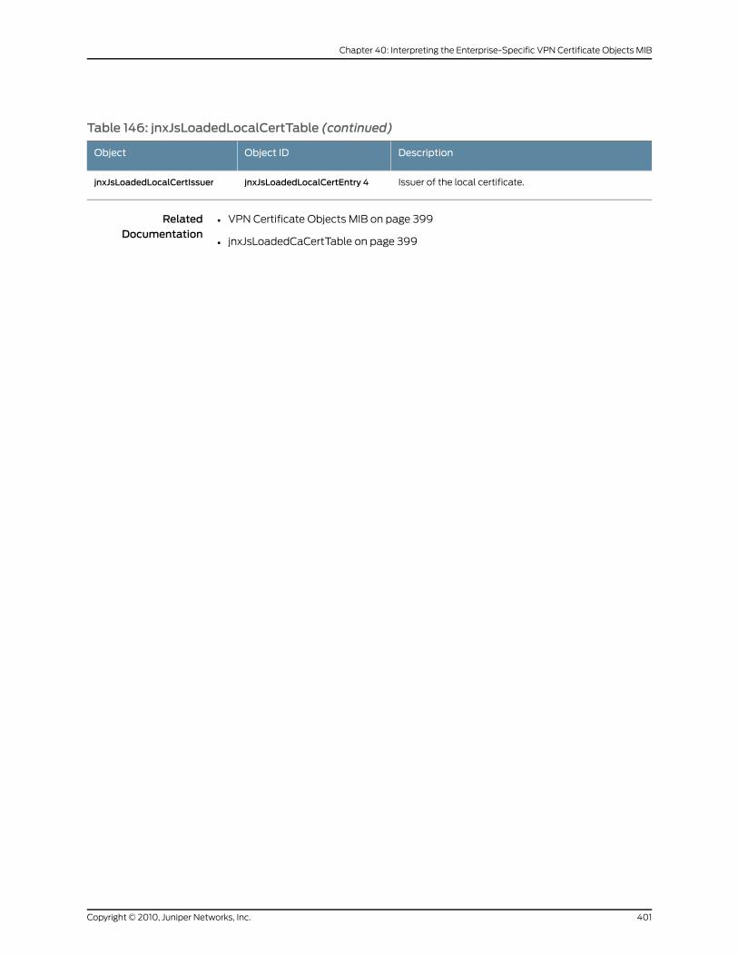
Table 146: jnxJsLoadedLocalCertTable (continued)
DescriptionObject IDObject
Issuer of the local certificate.jnxJsLoadedLocalCertEntry 4jnxJsLoadedLocalCertIssuer
RelatedDocumentation
• VPN Certificate Objects MIB on page 399
• jnxJsLoadedCaCertTable on page 399
401Copyright © 2010, Juniper Networks, Inc.
Chapter 40: Interpreting the Enterprise-Specific VPN Certificate Objects MIB

Copyright © 2010, Juniper Networks, Inc.402
SRX100, SRX210, SRX220, SRX240, and SRX650 Services Gateways MIB Reference

PART 4
Accounting Options
• Accounting Options Overview on page 405
• Configuring Accounting Options on page 407
403Copyright © 2010, Juniper Networks, Inc.

Copyright © 2010, Juniper Networks, Inc.404
SRX100, SRX210, SRX220, SRX240, and SRX650 Services Gateways MIB Reference

CHAPTER 41
Accounting Options Overview
This chapter contains the following topic:
• Accounting Options Overview on page 405
Accounting Options Overview
An accounting profile represents common characteristics of collected accounting data,
including the following:
• Collection interval
• File to contain accounting data
• Specific fields and counter names on which to collect statistics
You can configure multiple accounting profiles, as described in Table 147 on page 405.
Table 147: Types of Accounting Profiles
DescriptionType of Profile
Collects the specified error and statistic information.Interface profile
Collects the byte and packet counts for the counter namesspecified in the filter profile.
Filter profile
Collects selected MIB statistics and logs them to a specifiedfile.
MIB profile
Collects selected Routing Engine statistics and logs them toa specified file.
Routing Engine profile
Collects class usage statistics and logs them to a specifiedfile.
Class usage profile
RelatedDocumentation
• Understanding Device Management Functions in Junos OS on page 3
• Accounting Options Configuration on page 407
• Configuring Accounting-Data Log Files on page 410
405Copyright © 2010, Juniper Networks, Inc.

• Configuring the Interface Profile on page 413
• Configuring the Filter Profile on page 416
• Configuration Statements at the [edit accounting-options] Hierarchy Level
Copyright © 2010, Juniper Networks, Inc.406
SRX100, SRX210, SRX220, SRX240, and SRX650 Services Gateways MIB Reference
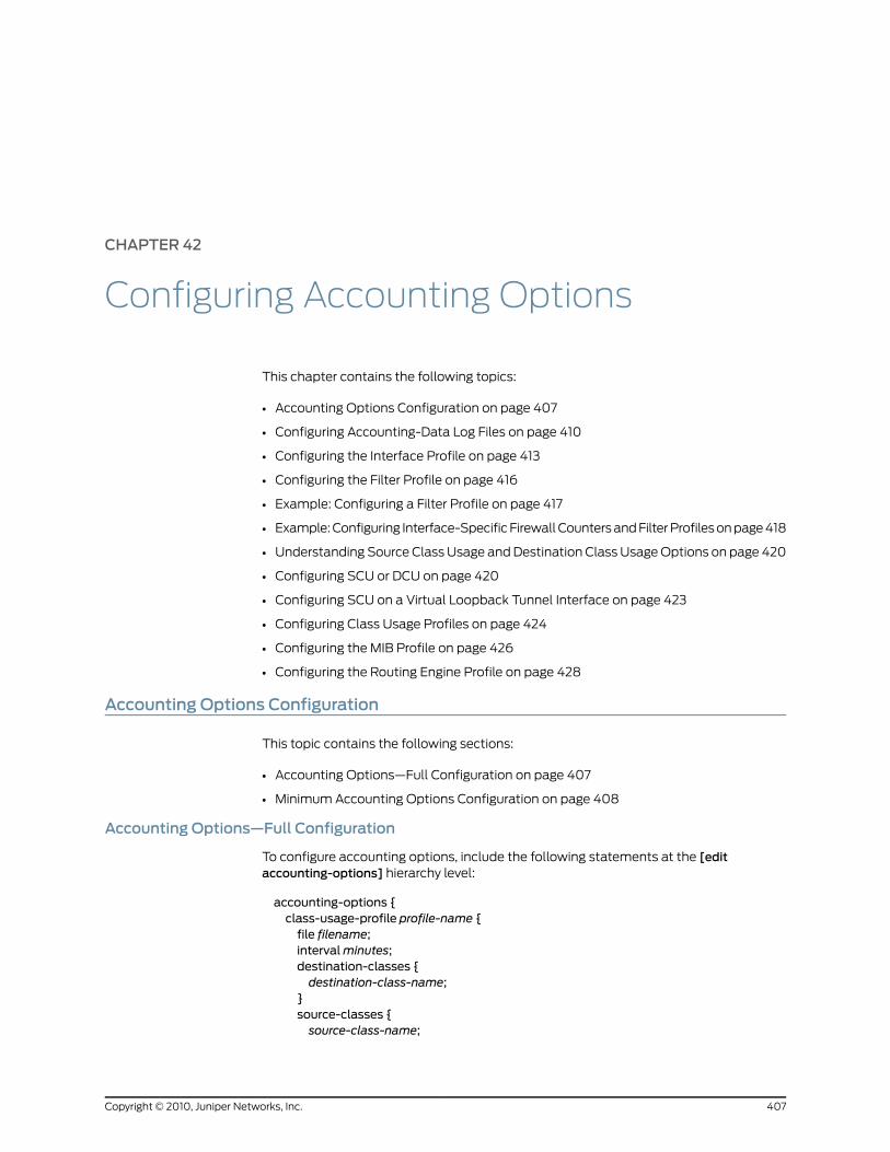
CHAPTER 42
Configuring Accounting Options
This chapter contains the following topics:
• Accounting Options Configuration on page 407
• Configuring Accounting-Data Log Files on page 410
• Configuring the Interface Profile on page 413
• Configuring the Filter Profile on page 416
• Example: Configuring a Filter Profile on page 417
• Example: Configuring Interface-Specific Firewall Counters and Filter Profiles on page 418
• Understanding Source Class Usage and Destination Class Usage Options on page 420
• Configuring SCU or DCU on page 420
• Configuring SCU on a Virtual Loopback Tunnel Interface on page 423
• Configuring Class Usage Profiles on page 424
• Configuring the MIB Profile on page 426
• Configuring the Routing Engine Profile on page 428
Accounting Options Configuration
This topic contains the following sections:
• Accounting Options—Full Configuration on page 407
• Minimum Accounting Options Configuration on page 408
Accounting Options—Full Configuration
To configure accounting options, include the following statements at the [editaccounting-options] hierarchy level:
accounting-options {class-usage-profile profile-name {file filename;intervalminutes;destination-classes {destination-class-name;
}source-classes {source-class-name;
407Copyright © 2010, Juniper Networks, Inc.

}file filename {archive-sites {site-name;
}files number;nonpersistent;size bytes;source-classes timetransfer-intervalminutes;
}filter-profile profile-name {counters {counter-name;
}file filename;intervalminutes;
}}interface-profile profile-name {fields {field-name;
}file filename;intervalminutes;
}mib-profile profile-name {file filename;interval seconds;object-names {mib-object-name;
}operation operation-name;
}routing-engine-profile profile-name {fields {field-name;
}file filename;intervalminutes;
}}
By default, accounting options are disabled.
MinimumAccounting Options Configuration
To enable accounting options on the router, you must perform at least the following
tasks:
• Configure accounting options by including a file statement and one or moresource-class-usage,destination-class-profile, filter-profile, interface-profile,mib-profile,or routing-engine-profile statements at the [edit accounting-options] hierarchy level:
[edit]accounting-options {
Copyright © 2010, Juniper Networks, Inc.408
SRX100, SRX210, SRX220, SRX240, and SRX650 Services Gateways MIB Reference
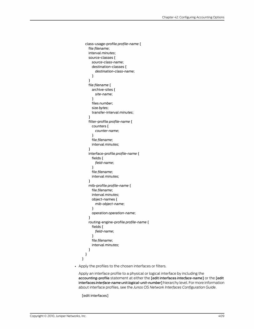
class-usage-profile profile-name {file filename;intervalminutes;source-classes {source-class-name;destination-classes {destination-class-name;
}}file filename {archive-sites {site-name;
}files number;size bytes;transfer-intervalminutes;
}filter-profile profile-name {counters {counter-name;
}file filename;intervalminutes;
}interface-profile profile-name {fields {field-name;
}file filename;intervalminutes;
}mib-profile profile-name {file filename;intervalminutes;object-names {mib-object-name;
}operation operation-name;
}routing-engine-profile profile-name {fields {field-name;
}file filename;intervalminutes;
}}
}
• Apply the profiles to the chosen interfaces or filters.
Apply an interface profile to a physical or logical interface by including theaccounting-profile statement at either the [edit interfaces interface-name] or the [editinterfaces interface-nameunit logical-unit-number]hierarchy level. For more informationabout interface profiles, see the Junos OS Network Interfaces Configuration Guide.
[edit interfaces]
409Copyright © 2010, Juniper Networks, Inc.
Chapter 42: Configuring Accounting Options
interface-name {accounting-profile profile-name;unit logical-unit-number {accounting-profile profile-name;
}}
NOTE: You do not apply destination class profiles to interfaces. Althoughthe interface needs to have the destination-class-usage statement
configured, the destination class profile automatically finds all interfaceswith the destination class configured.
Apply a filter profile to a firewall filter by including the accounting-profile statement atthe [edit firewall filter filter-name] hierarchy level:
[edit firewall]filter filter-name {accounting-profile profile-name;
}
You do not need to apply the Routing Engine profile to an interface because the
statistics are collected on the Routing Engine itself.
RelatedDocumentation
Accounting Options Overview on page 405•
• Understanding Device Management Functions in Junos OS on page 3
• Configuring Accounting-Data Log Files on page 410
• Configuring the Interface Profile on page 413
• Configuring the Filter Profile on page 416
• Configuration Statements at the [edit accounting-options] Hierarchy Level
Configuring Accounting-Data Log Files
An accounting profile specifies what statistics should be collected and written to a logfile. To configure an accounting-data log file, include the file statement at the [editaccounting-options] hierarchy level:
[edit accounting-options]file filename {archive-sites {site-name;
}files number;nonpersistent;size bytes;start-time time;transfer-intervalminutes;
}
filename is the name of the file in which to write accounting data.
Copyright © 2010, Juniper Networks, Inc.410
SRX100, SRX210, SRX220, SRX240, and SRX650 Services Gateways MIB Reference

If the filename contains spaces, enclose it in quotation marks (" "). The filename cannot
contain a forward slash (;/;). The file is created in the /var/log directory and can contain
data from multiple profiles.
All accounting-data log files include header and trailer sections that start with a # in the
first column. The header contains the file creation time, the hostname, and the columns
that appear in the file. The trailer contains the time that the file was closed.
Whenever any configured value changes that affects the columns in a file, the file creates
a new profile layout record that contains a new list of columns.
You must configure the file size; all other properties are optional.
• Configuring the Storage Location of the File on page 411
• Configuring the Maximum Size of the File on page 411
• Configuring the Maximum Number of Files on page 412
• Configuring the Start Time for File Transfer on page 412
• Configuring the Transfer Interval of the File on page 412
• Configuring Archive Sites on page 413
Configuring the Storage Location of the File
On J Series Services Routers, the files are stored by default on the compact flash drive.To configure the storage location of the files in the mfs/var/log directory (on DRAM)instead of the cf/var/logdirectory (on the compact flash drive), include thenonpersistentstatement at the [edit accounting-options file filename] hierarchy level:
[edit accounting-options file filename]nonpersistent;
This feature is useful for minimizing read/write traffic on the router’s compact flash drive.
NOTE: If log files for accounting data are stored onDRAM, these files are lostwhen you reboot the router. Therefore, you should back up these filesperiodically.
Configuring theMaximumSize of the File
To configure the maximum size of the files, include the size statement at the [editaccounting-options file filename] hierarchy level:
[edit accounting-options file filename]size bytes;
The size statement is the maximum size of the log file, in bytes, kilobytes (KB), megabytes
(MB), or gigabytes (GB). The minimum value for bytes is 256 KB. You must configure
bytes; the remaining attributes are optional.
411Copyright © 2010, Juniper Networks, Inc.
Chapter 42: Configuring Accounting Options

Configuring theMaximumNumber of Files
To configure the maximum number of files, include the files statement at the [editaccounting-options file filename] hierarchy level:
[edit accounting-options file filename]files number;
When a log file (for example, profilelog) reaches its maximum size, it is renamed
profilelog.0, thenprofilelog.1, and so on, until the maximum number of log files is reached.
Then the oldest log file is overwritten. The minimum value for number is 3 and the default
value is 10.
Configuring the Start Time for File Transfer
To configure the start time for transferring files, include the start-time statement at the[edit accounting-options file filename] hierarchy level:
[edit accounting-options file filename]start-time time;
The start-time statement specifies a start time for file transfer (YYYY-MM-DD.hh:mm).
For example, 10:00 a.m. on January 30, 2007 is represented as 2007-01-30.10:00.
Configuring the Transfer Interval of the File
To configure the transfer interval of the files, include the transfer-interval statement atthe [edit accounting-options file filename] hierarchy level:
[edit accounting-options file filename]transfer-intervalminutes;
The range for transfer-interval is 5 through 2880 minutes. The default is 30 minutes.
TIP:
Junos OS saves the existing log file and creates a new file at the configuredtransfer-intervals irrespective of:
• Whether the file has reached themaximum size or not
• Whether an archive site is configured or not
When you have a relatively smaller transfer-interval configured and if noarchive site is configured, there is a possibility of losing data as Junos OSoverwrites the log files when themaximum number of log files is reached.To ensure that the log information is saved for a reasonably long time:
• Configure an archive site to archive the log files every time a new log file iscreated.
• Configure themaximumvalue (2880minutes) for transfer-interval so that
new files are created less frequently; that is, onlywhen the file exceeds themaximum size limit or once in 2 days.
Copyright © 2010, Juniper Networks, Inc.412
SRX100, SRX210, SRX220, SRX240, and SRX650 Services Gateways MIB Reference
Configuring Archive Sites
After a file reaches its maximum size or the transfer-interval time is exceeded, the file isclosed, renamed, and, if you configured an archive site, transferred to a remote host. Toconfigure archive sites, include thearchive-sites statement at the [editaccounting-optionsfile filename] hierarchy level:
[edit accounting-options file filename]archive-sites {site-name;
}
site-name is any valid FTP URL. For more information about specifying valid FTP URLs,
see the JunosOSSystemBasics Configuration Guide. You can specify more than one URL,
in any order. When a file is archived, the router or switch attempts to transfer the file to
the first URL in the list, trying the next site in the list only if the transfer does not succeed.
The log file is stored at the archive site with a filename of the format
router-name_log-filename_timestamp.
RelatedDocumentation
Accounting Options Overview on page 405•
• Understanding Device Management Functions in Junos OS on page 3
• Accounting Options Configuration on page 407
• Configuring the Interface Profile on page 413
• Configuring the Filter Profile on page 416
• Configuration Statements at the [edit accounting-options] Hierarchy Level
Configuring the Interface Profile
An interface profile specifies the information collected and written to a log file. You can
configure a profile to collect error and statistic information for input and output packets
on a particular physical or logical interface.
To configure an interface profile, include the interface-profile statement at the[edit accounting-options] hierarchy level:
[edit accounting-options]interface-profile profile-name {fields {field-name;
}file filename;intervalminutes;
}
Each accounting profile must have a unique profile-name. To apply a profile to a physical
or logical interface, include the accounting-profile statement at either the [edit interfaces
interface-name] or the [edit interfaces interface-name unit logical-unit-number] hierarchy
level. You can also apply a accounting profile at the [edit firewall family family-type filter
filter-name] hierarchy level. For more information, see the Junos OS Policy Framework
Configuration Guide.
413Copyright © 2010, Juniper Networks, Inc.
Chapter 42: Configuring Accounting Options
To configure an interface profile, you perform the tasks described in the following sections:
• Configuring Fields on page 414
• Configuring the File Information on page 414
• Configuring the Interval on page 414
• Example: Configuring the Interface Profile on page 414
Configuring Fields
An interface profile must specify what statistics are collected. To configure which statisticsshould be collected for an interface, include the fields statement at the [editaccounting-options interface-profile profile-name] hierarchy level:
[edit accounting-options interface-profile profile-name]fields {field-name;
}
Configuring the File Information
Each accounting profile logs its statistics to a file in the /var/log directory.
To configure which file to use, include the file statement at the [edit accounting-optionsinterface-profile profile-name] hierarchy level:
[edit accounting-options interface-profile profile-name]file filename;
You must specify a file statement for the interface profile that has already been configured
at the [edit accounting-options] hierarchy level.
Configuring the Interval
Each interface with an accounting profile enabled has statistics collected once per intervaltime specified for the accounting profile. Statistics collection time is scheduled evenlyover the configured interval. To configure the interval, include the interval statement atthe [edit accounting-options interface-profile profile-name] hierarchy level:
[edit accounting-options interface-profile profile-name]intervalminutes;
NOTE: Theminimum interval allowed is 1 minute. Configuring a low intervalin an accounting profile for a large number of interfacesmight cause seriousperformance degradation.
The range for the interval statement is 1 through 2880 minutes. The default is 30 minutes.
Example: Configuring the Interface Profile
Configure the interface profile:
[edit]accounting-options {file if_stats {
Copyright © 2010, Juniper Networks, Inc.414
SRX100, SRX210, SRX220, SRX240, and SRX650 Services Gateways MIB Reference
size 40 files 5;}interface-profile if_profile1 {file if_stats;interval 30;fields {input-bytes;output-bytes;input-packets;output-packets;input-multicast;output-multicast;
}}interface-profile if_profile2 {file if_stats;interval 30;fields {input-bytes;output-bytes;input-packets;output-packets;input-multicast;output-multicast;
}}interfaces {xe-1/0/0 {accounting-profile if_profile1;unit 0 {accounting-profile if_profile2;...
}}
}}
The two interface profiles, if-profile1 and if-profile2, write data to the same file, if-stats.
The if-stats file might look like the following:
#FILE CREATED 976823478 2000-12-14-19:51:18#hostname host#profile-layout if_profile2,epoch-timestamp,interface-name,snmp-index,input-bytes,output-bytes,input-packets,output-packets,input-multicast,output-multicast#profile-layout if_profile1,epoch-timestamp,interface-name,snmp-index,input-bytes,output-bytes,input-packetsif_profile2,976823538,xe-1/0/0.0,8,134696815,3681534,501088,40723,0,0if_profile1,976823538,xe-1/0/0,7,134696815,3681534,501088...#FILE CLOSED 976824378 2000-12-14-20:06:18
RelatedDocumentation
Accounting Options Overview on page 405•
• Understanding Device Management Functions in Junos OS on page 3
415Copyright © 2010, Juniper Networks, Inc.
Chapter 42: Configuring Accounting Options
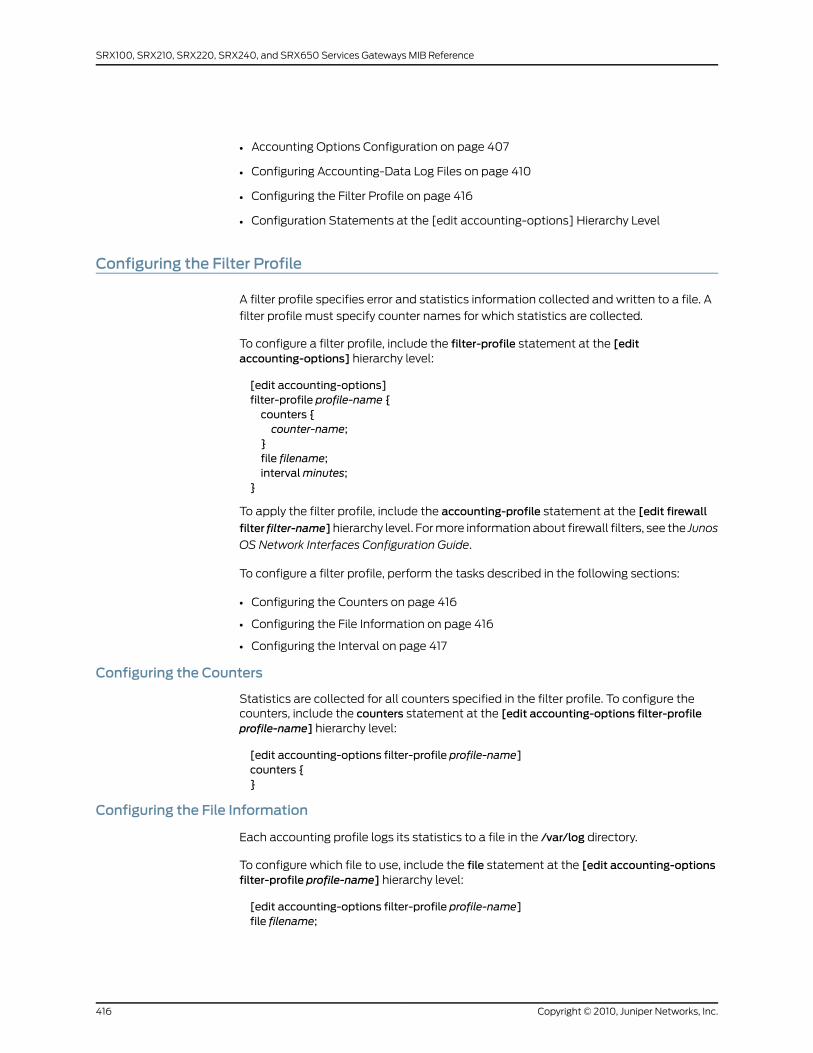
• Accounting Options Configuration on page 407
• Configuring Accounting-Data Log Files on page 410
• Configuring the Filter Profile on page 416
• Configuration Statements at the [edit accounting-options] Hierarchy Level
Configuring the Filter Profile
A filter profile specifies error and statistics information collected and written to a file. A
filter profile must specify counter names for which statistics are collected.
To configure a filter profile, include the filter-profile statement at the [editaccounting-options] hierarchy level:
[edit accounting-options]filter-profile profile-name {counters {counter-name;
}file filename;intervalminutes;
}
To apply the filter profile, include the accounting-profile statement at the [edit firewall
filter filter-name]hierarchy level. For more information about firewall filters, see the Junos
OS Network Interfaces Configuration Guide.
To configure a filter profile, perform the tasks described in the following sections:
• Configuring the Counters on page 416
• Configuring the File Information on page 416
• Configuring the Interval on page 417
Configuring the Counters
Statistics are collected for all counters specified in the filter profile. To configure thecounters, include the counters statement at the [edit accounting-options filter-profileprofile-name] hierarchy level:
[edit accounting-options filter-profile profile-name]counters {}
Configuring the File Information
Each accounting profile logs its statistics to a file in the /var/log directory.
To configure which file to use, include the file statement at the [edit accounting-optionsfilter-profile profile-name] hierarchy level:
[edit accounting-options filter-profile profile-name]file filename;
Copyright © 2010, Juniper Networks, Inc.416
SRX100, SRX210, SRX220, SRX240, and SRX650 Services Gateways MIB Reference
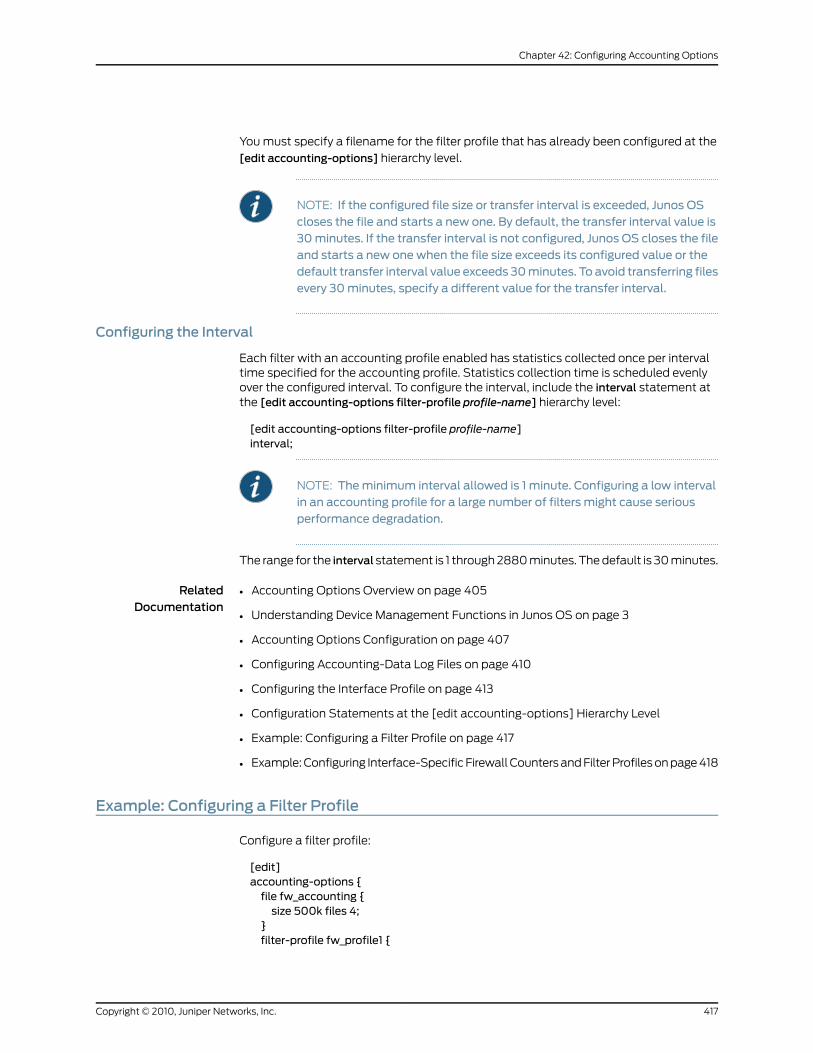
You must specify a filename for the filter profile that has already been configured at the
[edit accounting-options] hierarchy level.
NOTE: If the configured file size or transfer interval is exceeded, Junos OScloses the file and starts a new one. By default, the transfer interval value is30minutes. If the transfer interval is not configured, Junos OS closes the fileand starts a new one when the file size exceeds its configured value or thedefault transfer interval value exceeds 30minutes. To avoid transferring filesevery 30minutes, specify a different value for the transfer interval.
Configuring the Interval
Each filter with an accounting profile enabled has statistics collected once per intervaltime specified for the accounting profile. Statistics collection time is scheduled evenlyover the configured interval. To configure the interval, include the interval statement atthe [edit accounting-options filter-profile profile-name] hierarchy level:
[edit accounting-options filter-profile profile-name]interval;
NOTE: Theminimum interval allowed is 1 minute. Configuring a low intervalin an accounting profile for a large number of filters might cause seriousperformance degradation.
The range for the interval statement is 1 through 2880 minutes. The default is 30 minutes.
RelatedDocumentation
Accounting Options Overview on page 405•
• Understanding Device Management Functions in Junos OS on page 3
• Accounting Options Configuration on page 407
• Configuring Accounting-Data Log Files on page 410
• Configuring the Interface Profile on page 413
• Configuration Statements at the [edit accounting-options] Hierarchy Level
• Example: Configuring a Filter Profile on page 417
• Example: Configuring Interface-Specific Firewall Counters and Filter Profiles on page 418
Example: Configuring a Filter Profile
Configure a filter profile:
[edit]accounting-options {file fw_accounting {size 500k files 4;
}filter-profile fw_profile1 {
417Copyright © 2010, Juniper Networks, Inc.
Chapter 42: Configuring Accounting Options
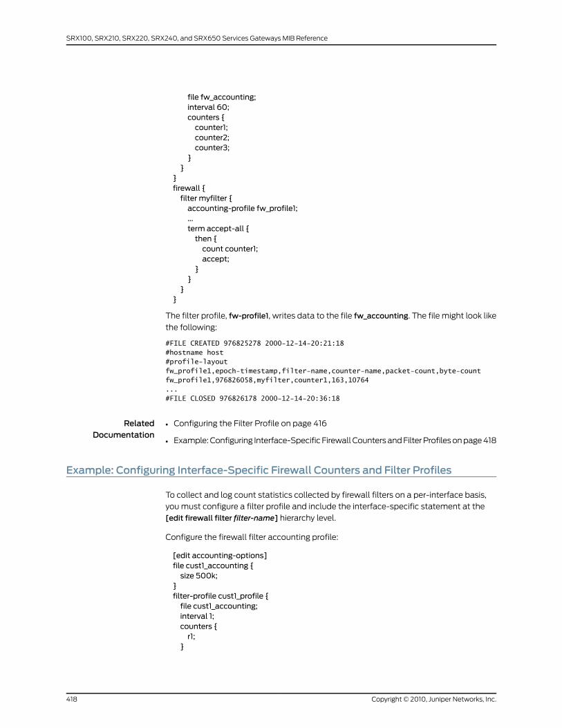
file fw_accounting;interval 60;counters {counter1;counter2;counter3;
}}
}firewall {filter myfilter {accounting-profile fw_profile1;...term accept-all {then {count counter1;accept;
}}
}}
The filter profile, fw-profile1, writes data to the file fw_accounting. The file might look like
the following:
#FILE CREATED 976825278 2000-12-14-20:21:18#hostname host#profile-layout fw_profile1,epoch-timestamp,filter-name,counter-name,packet-count,byte-countfw_profile1,976826058,myfilter,counter1,163,10764...#FILE CLOSED 976826178 2000-12-14-20:36:18
RelatedDocumentation
Configuring the Filter Profile on page 416•
• Example: Configuring Interface-Specific Firewall Counters and Filter Profiles on page 418
Example: Configuring Interface-Specific Firewall Counters and Filter Profiles
To collect and log count statistics collected by firewall filters on a per-interface basis,
you must configure a filter profile and include the interface-specific statement at the
[edit firewall filter filter-name] hierarchy level.
Configure the firewall filter accounting profile:
[edit accounting-options]file cust1_accounting {size 500k;
}filter-profile cust1_profile {file cust1_accounting;interval 1;counters {r1;
}
Copyright © 2010, Juniper Networks, Inc.418
SRX100, SRX210, SRX220, SRX240, and SRX650 Services Gateways MIB Reference
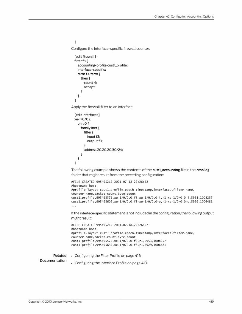
}
Configure the interface-specific firewall counter:
[edit firewall]filter f3 {accounting-profile cust1_profile;interface-specific;term f3-term {then {count r1;accept;
}}
}
Apply the firewall filter to an interface:
[edit interfaces]xe-1/0/0 {unit 0 {family inet {filter {input f3;output f3;
}address 20.20.20.30/24;
}}
}
The following example shows the contents of the cust1_accounting file in the /var/log
folder that might result from the preceding configuration:
#FILE CREATED 995495212 2001-07-18-22:26:52#hostname host#profile-layout cust1_profile,epoch-timestamp,interfaces,filter-name,counter-name,packet-count,byte-countcust1_profile,995495572,xe-1/0/0.0,f3-xe-1/0/0.0-i,r1-xe-1/0/0.0-i,5953,1008257cust1_profile,995495602,xe-1/0/0.0,f3-xe-1/0/0.0-o,r1-xe-1/0/0.0-o,5929,1006481...
If the interface-specific statement is not included in the configuration, the following output
might result:
#FILE CREATED 995495212 2001-07-18-22:26:52#hostname host#profile-layout cust1_profile,epoch-timestamp,interfaces,filter-name,counter-name,packet-count,byte-countcust1_profile,995495572,xe-1/0/0.0,f3,r1,5953,1008257cust1_profile,995495632,xe-1/0/0.0,f3,r1,5929,1006481
RelatedDocumentation
Configuring the Filter Profile on page 416•
• Configuring the Interface Profile on page 413
419Copyright © 2010, Juniper Networks, Inc.
Chapter 42: Configuring Accounting Options

Understanding Source Class Usage and Destination Class Usage Options
You can maintain packet counts based on the entry and exit points for traffic passing
through your network. Entry and exit points are identified by source and destination
prefixes grouped into disjoint sets defined as source classes and destination classes. You
can define classes based on a variety of parameters, such as routing neighbors,
autonomous systems, and route filters.
Source class usage (SCU) counts packets sent to customers by performing lookup on
the IP source address and the IP destination address. SCU makes it possible to track
traffic originating from specific prefixes on the provider core and destined for specific
prefixes on the customer edge. You must enable SCU accounting on both the inbound
and outbound physical interfaces.
Destination class usage (DCU) counts packets from customers by performing lookup of
the IP destination address. DCU makes it possible to track traffic originating from the
customer edge and destined for specific prefixes on the provider core router.
On T Series and M320 routers, the source class and destination classes are not carried
across the platform fabric. The implications of this are as follows:
• On T Series and M320 routers, SCU and DCU accounting is performed before the packet
enters the fabric.
• On T Series and M320 routers, DCU is performed before output filters are evaluated.
On M Series platforms, DCU is performed after output filters are evaluated.
• If an output filter drops traffic on M Series platforms, the dropped packets are excluded
from DCU statistics. If an output filter drops traffic on T Series and M320 routers, the
dropped packets are included in DCU statistics.
Class-based filter match conditions are not supported on J Series Services Routers.
For more information about source class usage, see the Junos OS Policy Framework
Configuration Guide, the Junos OS Network Interfaces Configuration Guide, and the Junos
OS Feature Guide.
RelatedDocumentation
Configuring SCU or DCU on page 420•
• Configuring SCU on a Virtual Loopback Tunnel Interface on page 423
• Configuring Class Usage Profiles on page 424
• Configuring the MIB Profile on page 426
• Configuring the Routing Engine Profile on page 428
Configuring SCU or DCU
To configure SCU or DCU, perform the following tasks described in this section:
Copyright © 2010, Juniper Networks, Inc.420
SRX100, SRX210, SRX220, SRX240, and SRX650 Services Gateways MIB Reference
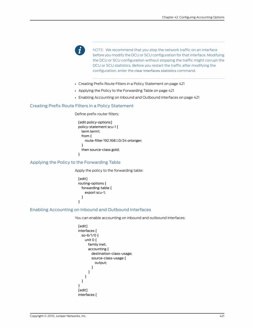
NOTE: We recommend that you stop the network traffic on an interfacebefore youmodify theDCUorSCUconfiguration for that interface.Modifyingthe DCU or SCU configuration without stopping the traffic might corrupt theDCU or SCU statistics. Before you restart the traffic after modifying theconfiguration, enter the clear interfaces statistics command.
• Creating Prefix Route Filters in a Policy Statement on page 421
• Applying the Policy to the Forwarding Table on page 421
• Enabling Accounting on Inbound and Outbound Interfaces on page 421
Creating Prefix Route Filters in a Policy Statement
Define prefix router filters:
[edit policy-options]policy-statement scu-1 {term term1;from {route-filter 192.168.1.0/24 orlonger;
}then source-class gold;
}
Applying the Policy to the Forwarding Table
Apply the policy to the forwarding table:
[edit]routing-options {forwarding-table {export scu-1;
}}
Enabling Accounting on Inbound and Outbound Interfaces
You can enable accounting on inbound and outbound interfaces:
[edit]interfaces {so-6/1/0 {unit 0 {family inet;accounting {destination-class-usage;source-class-usage {output;
}}
}}
}[edit]interfaces {
421Copyright © 2010, Juniper Networks, Inc.
Chapter 42: Configuring Accounting Options
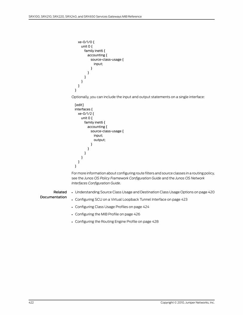
xe-0/1/0 {unit 0 {family inet6 {accounting {source-class-usage {input;
}}
}}
}}
Optionally, you can include the input and output statements on a single interface:
[edit]interfaces {xe-0/1/2 {unit 0 {family inet6 {accounting {source-class-usage {input;output;
}}
}}
}}
For more information about configuring route filters and source classes in a routing policy,
see the Junos OS Policy Framework Configuration Guide and the Junos OS Network
Interfaces Configuration Guide.
RelatedDocumentation
Understanding Source Class Usage and Destination Class Usage Options on page 420•
• Configuring SCU on a Virtual Loopback Tunnel Interface on page 423
• Configuring Class Usage Profiles on page 424
• Configuring the MIB Profile on page 426
• Configuring the Routing Engine Profile on page 428
Copyright © 2010, Juniper Networks, Inc.422
SRX100, SRX210, SRX220, SRX240, and SRX650 Services Gateways MIB Reference
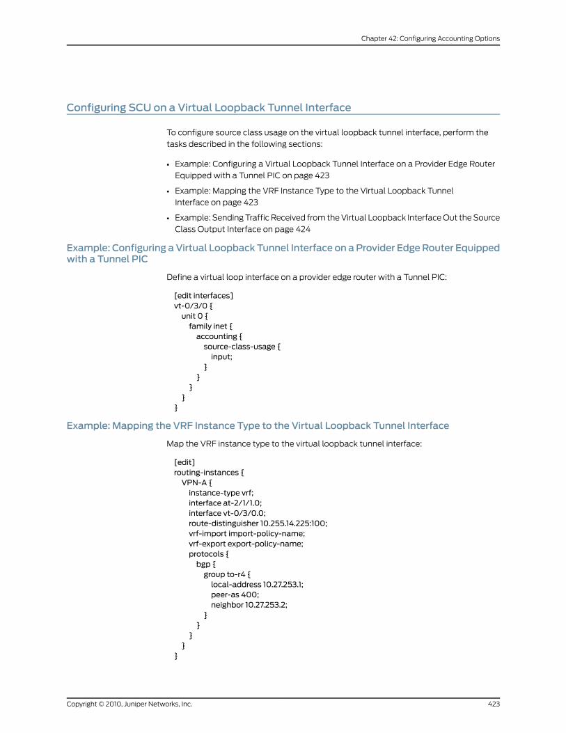
Configuring SCU on a Virtual Loopback Tunnel Interface
To configure source class usage on the virtual loopback tunnel interface, perform the
tasks described in the following sections:
• Example: Configuring a Virtual Loopback Tunnel Interface on a Provider Edge Router
Equipped with a Tunnel PIC on page 423
• Example: Mapping the VRF Instance Type to the Virtual Loopback Tunnel
Interface on page 423
• Example: Sending Traffic Received from the Virtual Loopback Interface Out the Source
Class Output Interface on page 424
Example: Configuring aVirtual Loopback Tunnel Interface on aProvider EdgeRouter Equippedwith a Tunnel PIC
Define a virtual loop interface on a provider edge router with a Tunnel PIC:
[edit interfaces]vt-0/3/0 {unit 0 {family inet {accounting {source-class-usage {input;
}}
}}
}
Example: Mapping the VRF Instance Type to the Virtual Loopback Tunnel Interface
Map the VRF instance type to the virtual loopback tunnel interface:
[edit]routing-instances {VPN-A {instance-type vrf;interface at-2/1/1.0;interface vt-0/3/0.0;route-distinguisher 10.255.14.225:100;vrf-import import-policy-name;vrf-export export-policy-name;protocols {bgp {group to-r4 {local-address 10.27.253.1;peer-as 400;neighbor 10.27.253.2;
}}
}}
}
423Copyright © 2010, Juniper Networks, Inc.
Chapter 42: Configuring Accounting Options

NOTE: ForSCUandDCUtowork,donot include thevrf-table-labelstatement
at the [edit routing-instances instance-name] hierarchy level.
Example: Sending Traffic Received from the Virtual Loopback Interface Out the Source ClassOutput Interface
Send traffic received from the virtual loopback tunnel interface out of the source classoutput interface:
[edit interfaces]at-1/1/0 {unit 0 {family inet {accounting {source-class-usage {output;
}}
}}
}
For more information about configuring source class usage on the virtual loopback tunnel
interface, see the Junos OS Network Interfaces Configuration Guide.
RelatedDocumentation
Understanding Source Class Usage and Destination Class Usage Options on page 420•
• Configuring SCU or DCU on page 420
• Configuring Class Usage Profiles on page 424
• Configuring the MIB Profile on page 426
• Configuring the Routing Engine Profile on page 428
Configuring Class Usage Profiles
To collect class usage statistics, perform the tasks described in these sections:
• Configuring a Class Usage Profile on page 424
• Configuring the File Information on page 425
• Configuring the Interval on page 425
• Creating a Class Usage Profile to Collect Source Class Usage Statistics on page 425
• Creating a Class Usage Profile to Collect Destination Class Usage Statistics on page 426
Configuring a Class Usage Profile
You can configure the class usage profile to collect statistics for particular source and
destination classes.
Copyright © 2010, Juniper Networks, Inc.424
SRX100, SRX210, SRX220, SRX240, and SRX650 Services Gateways MIB Reference
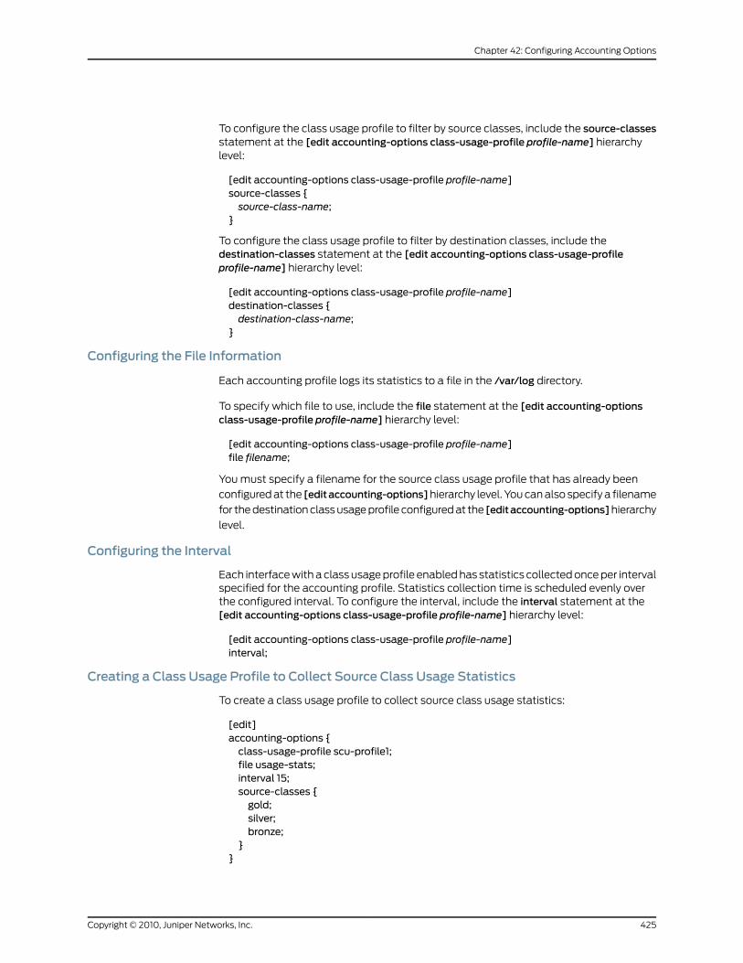
To configure the class usage profile to filter by source classes, include the source-classesstatement at the [edit accounting-options class-usage-profile profile-name] hierarchylevel:
[edit accounting-options class-usage-profile profile-name]source-classes {source-class-name;
}
To configure the class usage profile to filter by destination classes, include thedestination-classes statement at the [edit accounting-options class-usage-profileprofile-name] hierarchy level:
[edit accounting-options class-usage-profile profile-name]destination-classes {destination-class-name;
}
Configuring the File Information
Each accounting profile logs its statistics to a file in the /var/log directory.
To specify which file to use, include the file statement at the [edit accounting-optionsclass-usage-profile profile-name] hierarchy level:
[edit accounting-options class-usage-profile profile-name]file filename;
You must specify a filename for the source class usage profile that has already been
configured at the [editaccounting-options]hierarchy level. You can also specify a filename
for the destination class usage profile configured at the [editaccounting-options]hierarchy
level.
Configuring the Interval
Each interface with a class usage profile enabled has statistics collected once per intervalspecified for the accounting profile. Statistics collection time is scheduled evenly overthe configured interval. To configure the interval, include the interval statement at the[edit accounting-options class-usage-profile profile-name] hierarchy level:
[edit accounting-options class-usage-profile profile-name]interval;
Creating a Class Usage Profile to Collect Source Class Usage Statistics
To create a class usage profile to collect source class usage statistics:
[edit]accounting-options {class-usage-profile scu-profile1;file usage-stats;interval 15;source-classes {gold;silver;bronze;
}}
425Copyright © 2010, Juniper Networks, Inc.
Chapter 42: Configuring Accounting Options
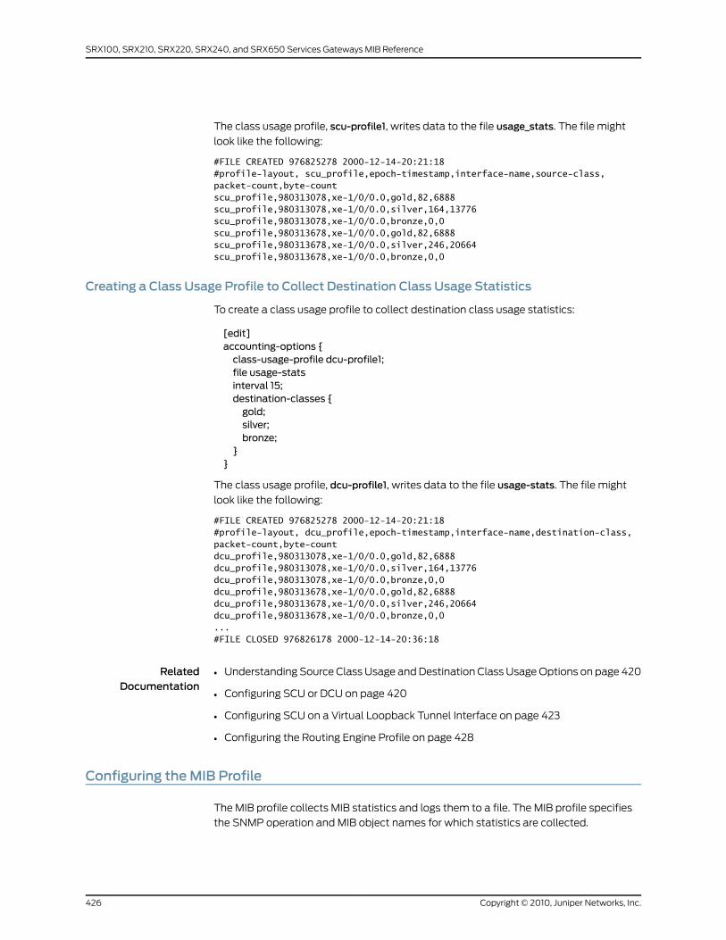
The class usage profile, scu-profile1, writes data to the file usage_stats. The file might
look like the following:
#FILE CREATED 976825278 2000-12-14-20:21:18#profile-layout, scu_profile,epoch-timestamp,interface-name,source-class,packet-count,byte-countscu_profile,980313078,xe-1/0/0.0,gold,82,6888scu_profile,980313078,xe-1/0/0.0,silver,164,13776scu_profile,980313078,xe-1/0/0.0,bronze,0,0scu_profile,980313678,xe-1/0/0.0,gold,82,6888scu_profile,980313678,xe-1/0/0.0,silver,246,20664scu_profile,980313678,xe-1/0/0.0,bronze,0,0
Creating a Class Usage Profile to Collect Destination Class Usage Statistics
To create a class usage profile to collect destination class usage statistics:
[edit]accounting-options {class-usage-profile dcu-profile1;file usage-statsinterval 15;destination-classes {gold;silver;bronze;
}}
The class usage profile, dcu-profile1, writes data to the file usage-stats. The file might
look like the following:
#FILE CREATED 976825278 2000-12-14-20:21:18#profile-layout, dcu_profile,epoch-timestamp,interface-name,destination-class,packet-count,byte-countdcu_profile,980313078,xe-1/0/0.0,gold,82,6888dcu_profile,980313078,xe-1/0/0.0,silver,164,13776dcu_profile,980313078,xe-1/0/0.0,bronze,0,0dcu_profile,980313678,xe-1/0/0.0,gold,82,6888dcu_profile,980313678,xe-1/0/0.0,silver,246,20664dcu_profile,980313678,xe-1/0/0.0,bronze,0,0...#FILE CLOSED 976826178 2000-12-14-20:36:18
RelatedDocumentation
Understanding Source Class Usage and Destination Class Usage Options on page 420•
• Configuring SCU or DCU on page 420
• Configuring SCU on a Virtual Loopback Tunnel Interface on page 423
• Configuring the Routing Engine Profile on page 428
Configuring theMIB Profile
The MIB profile collects MIB statistics and logs them to a file. The MIB profile specifies
the SNMP operation and MIB object names for which statistics are collected.
Copyright © 2010, Juniper Networks, Inc.426
SRX100, SRX210, SRX220, SRX240, and SRX650 Services Gateways MIB Reference
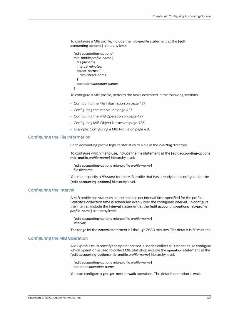
To configure a MIB profile, include the mib-profile statement at the [editaccounting-options] hierarchy level:
[edit accounting-options]mib-profile profile-name {file filename;intervalminutes;object-names {mib-object-name;
}operation operation-name;
}
To configure a MIB profile, perform the tasks described in the following sections:
• Configuring the File Information on page 427
• Configuring the Interval on page 427
• Configuring the MIB Operation on page 427
• Configuring MIB Object Names on page 428
• Example: Configuring a MIB Profile on page 428
Configuring the File Information
Each accounting profile logs its statistics to a file in the /var/log directory.
To configure which file to use, include the file statement at the [edit accounting-optionsmib-profile profile-name] hierarchy level:
[edit accounting-optionsmib-profile profile-name]file filename;
You must specify a filename for the MIB profile that has already been configured at the
[edit accounting-options] hierarchy level.
Configuring the Interval
A MIB profile has statistics collected once per interval time specified for the profile.Statistics collection time is scheduled evenly over the configured interval. To configurethe interval, include the interval statement at the [edit accounting-optionsmib-profileprofile-name] hierarchy level:
[edit accounting-optionsmib-profile profile-name]interval;
The range for the interval statement is 1 through 2880 minutes. The default is 30 minutes.
Configuring theMIB Operation
A MIB profile must specify the operation that is used to collect MIB statistics. To configurewhich operation is used to collect MIB statistics, include the operation statement at the[edit accounting-optionsmib-profile profile-name] hierarchy level:
[edit accounting-optionsmib-profile profile-name]operation operation-name;
You can configure a get, get-next, or walk operation. The default operation is walk.
427Copyright © 2010, Juniper Networks, Inc.
Chapter 42: Configuring Accounting Options
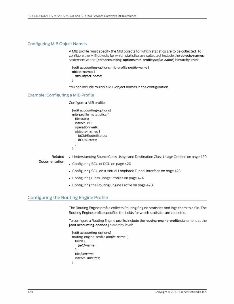
ConfiguringMIB Object Names
A MIB profile must specify the MIB objects for which statistics are to be collected. Toconfigure the MIB objects for which statistics are collected, include the objects-namesstatement at the [edit accounting-optionsmib-profile profile-name] hierarchy level:
[edit accounting-optionsmib-profile profile-name]object-names {mib-object-name;
}
You can include multiple MIB object names in the configuration.
Example: Configuring aMIB Profile
Configure a MIB profile:
[edit accounting-options]mib-profile mstatistics {file stats;interval 60;operation walk;objects-names {ipCidrRouteStatus;ifOutOctets;
}}
RelatedDocumentation
Understanding Source Class Usage and Destination Class Usage Options on page 420•
• Configuring SCU or DCU on page 420
• Configuring SCU on a Virtual Loopback Tunnel Interface on page 423
• Configuring Class Usage Profiles on page 424
• Configuring the Routing Engine Profile on page 428
Configuring the Routing Engine Profile
The Routing Engine profile collects Routing Engine statistics and logs them to a file. The
Routing Engine profile specifies the fields for which statistics are collected.
To configure a Routing Engine profile, include the routing-engine-profile statement at the[edit accounting-options] hierarchy level:
[edit accounting-options]routing-engine-profile profile-name {fields {field-name;
}file filename;intervalminutes;
}
Copyright © 2010, Juniper Networks, Inc.428
SRX100, SRX210, SRX220, SRX240, and SRX650 Services Gateways MIB Reference
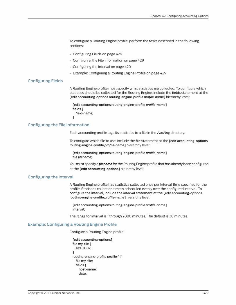
To configure a Routing Engine profile, perform the tasks described in the following
sections:
• Configuring Fields on page 429
• Configuring the File Information on page 429
• Configuring the Interval on page 429
• Example: Configuring a Routing Engine Profile on page 429
Configuring Fields
A Routing Engine profile must specify what statistics are collected. To configure whichstatistics should be collected for the Routing Engine, include the fields statement at the[edit accounting-options routing-engine-profile profile-name] hierarchy level:
[edit accounting-options routing-engine-profile profile-name]fields {field-name;
}
Configuring the File Information
Each accounting profile logs its statistics to a file in the /var/log directory.
To configure which file to use, include the file statement at the [edit accounting-optionsrouting-engine-profile profile-name] hierarchy level:
[edit accounting-options routing-engine-profile profile-name]file filename;
You must specify a filename for the Routing Engine profile that has already been configured
at the [edit accounting-options] hierarchy level.
Configuring the Interval
A Routing Engine profile has statistics collected once per interval time specified for theprofile. Statistics collection time is scheduled evenly over the configured interval. Toconfigure the interval, include the interval statement at the [edit accounting-optionsrouting-engine-profile profile-name] hierarchy level:
[edit accounting-options routing-engine-profile profile-name]interval;
The range for interval is 1 through 2880 minutes. The default is 30 minutes.
Example: Configuring a Routing Engine Profile
Configure a Routing Engine profile:
[edit accounting-options]file my-file {size 300k;
}routing-engine-profile profile-1 {file my-file;fields {host-name;date;
429Copyright © 2010, Juniper Networks, Inc.
Chapter 42: Configuring Accounting Options
time-of-day;uptime;cpu-load-1;cpu-load-5;cpu-load-15;
}}
RelatedDocumentation
• Understanding Source Class Usage and Destination Class Usage Options on page 420
• Configuring SCU or DCU on page 420
• Configuring SCU on a Virtual Loopback Tunnel Interface on page 423
• Configuring Class Usage Profiles on page 424
• Configuring the MIB Profile on page 426
Copyright © 2010, Juniper Networks, Inc.430
SRX100, SRX210, SRX220, SRX240, and SRX650 Services Gateways MIB Reference

PART 5
Index
• Index on page 433
431Copyright © 2010, Juniper Networks, Inc.

Copyright © 2010, Juniper Networks, Inc.432
SRX100, SRX210, SRX220, SRX240, and SRX650 Services Gateways MIB Reference
Index
Symbols#, comments in configuration statements..................xxii
( ), in syntax descriptions...................................................xxii
/var/log/mib2d file.................................................................54
/var/log/snmpd file................................................................54
< >, in syntax descriptions...................................................xxi
[ ], in configuration statements.......................................xxii
{ }, in configuration statements.......................................xxii
| (pipe), in syntax descriptions.........................................xxii
AAAA Objects MIB.....................................................................24
Access Authentication Objects MIB................24, 145, 161
access-list statement...........................................................93
accounting options
configuration.................................................................407
overview.........................................................................405
accounting profiles
filter...................................................................................416
interface...........................................................................413
MIB....................................................................................426
Routing Engine.............................................................428
agent, SNMP..............................................................................12
agent-address statement...................................................94
Alarm MIB................................................................24, 145, 165
Analyzer MIB.............................................................................24
archive-sites statement
accounting
usage guidelines..................................................413
ATM CoS MIB............................................................................24
ATM MIB.....................................................................................24
authorization statement......................................................94
usage guidelines.............................................................43
BBFD MIB......................................................................25, 146, 171
notification variables...................................................172
BGP4 V2 MIB..........................................................25, 145, 169
braces, in configuration statements...............................xxii
brackets
angle, in syntax descriptions.....................................xxi
square, in configuration statements......................xxii
Ccategories statement............................................................95
usage guidelines.............................................................49
Chassis Definitions for Router Model MIB...........25, 265
Chassis Forwarding MIB.......................................................25
Chassis MIB......................................................................25, 146
jnxBoxAnatomy.............................................................175
jnxBoxKernelMemoryUsedPercent......................260
jnxBoxSystemDomainType ....................................260
jnxMIBs..............................................................................175
jnxTraps..........................................................................260
overview............................................................................173
Class 1 MIB objects...............................................................138
Class 2 MIB objects...............................................................142
Class 3 MIB objects...............................................................143
Class 4 MIB objects..............................................................144
Class-of-Service MIB.............................................................25
class-usage-profile statement
usage guidelines..........................................................424
client list
adding to SNMP community.....................................44
client-list statement..............................................................95
usage guidelines.............................................................44
client-list-name statement................................................96
usage guidelines.............................................................44
clients statement...................................................................96
usage guidelines.............................................................43
comments, in configuration statements......................xxii
commit-delay statement.....................................................97
usage guidelines.............................................................42
community statement
SNMP.................................................................................98
usage guidelines....................................................43
community string, SNMP.....................................................43
Configuration Management MIB..............................25, 146
contact statement.................................................................99
usage guidelines............................................................40
433Copyright © 2010, Juniper Networks, Inc.
conventions
text and syntax...............................................................xxi
CoS
MIB.......................................................................................25
curly braces, in configuration statements....................xxii
customer support..................................................................xxii
contacting JTAC.............................................................xxii
Ddescription statement
SNMP.................................................................................99
usage guidelines.....................................................41
Destination Class Usage MIB.............................................26
destination-classes statement
usage guidelines..........................................................424
destination-port statement
SNMP...............................................................................100
usage guidelines....................................................49
Digital Optical Monitoring MIB...........................................26
DNS Objects MIB....................................................................26
Dynamic Flow Capture MIB................................................26
notification variables..................................................278
Eengine-id statement
SNMPv3
usage guidelines....................................................57
enterprise-specific MIBs, listed........................................145
enterprise-specific traps, SNMP
version 1..............................................................................74
version 2..............................................................................81
Ethernet MAC MIB................................................26, 146, 275
Event MIB.................................................................26, 146, 277
Experimental MIB....................................................................27
Ffields statement
for interface profiles
usage guidelines..................................................414
for Routing Engine profiles
usage guidelines.................................................429
file statement
accounting (associating with profile)
usage guidelines (filter profile)......................416
usage guidelines (interface profile).............414
usage guidelines (MIB profile).......................427
usage guidelines (Routing Engine
profile)................................................................429
accounting (configuring log file)
usage guidelines..................................................410
filter profile..............................................................................416
filter-duplicates statement..............................................100
usage guidelines..............................................................41
filter-interfaces statement.................................................101
filter-profile statement
usage guidelines...........................................................416
filtering get SNMP requests.................................................41
Firewall MIB......................................................................27, 146
Flow Collection Services MIB....................................27, 335
font conventions.....................................................................xxi
GGet requests, SNMP.................................................................9
HHost Resources MIB.............................................27, 147, 283
Iicons defined, notice...............................................................xx
IDP attack log notification................................................388
IDP attack Table....................................................................387
IDP MIB...............................................................................27, 149
ifChassisTable.......................................................................288
informs SNMP See SNMP informs
Interface MIB...........................................................27, 147, 285
interface profile......................................................................413
interface statement
SNMP................................................................................102
usage guidelines....................................................52
interface-profile statement
usage guidelines...........................................................413
interfaces limiting SNMP access.......................................52
interval statement
accounting
usage guidelines (filter profile).......................417
usage guidelines (interface profile).............414
usage guidelines (MIB profile).......................427
usage guidelines (Routing Engine
profile)................................................................429
IP Forward MIB........................................................27, 147, 291
IPsec Generic Flow Monitoring Object
MIB.........................................................................28, 147, 293
Text Conventions.........................................................294
IPsec Monitoring MIB..........................................28, 147, 309
Copyright © 2010, Juniper Networks, Inc.434
SRX100, SRX210, SRX220, SRX240, and SRX650 Services Gateways MIB Reference
IPsec Phase 1 IKE Tunnel Table......................................298
IPsec Phase 2 IKE Tunnel Table......................................302
IPsec Phase 2 Security Association Table..................305
IPsec VPN Objects MIB.........................................................28
IPv4 MIB.....................................................................28, 147, 317
IPv6 and ICMPv6 MIB...........................................................28
IPv6 SNMP community string............................................43
JjnxBfdSessTable......................................................................171
jnxBgpM2PrefixCountersTable........................................170
jnxBoxAnatomy MIB.............................................................175
jnxBoxKernelMemoryUsedPercent...............................260
jnxBoxSystemDomainType ............................................260
jnxContainersTable
M160 router.....................................................................179
M20 router.......................................................................178
M40 router......................................................................178
M40e router....................................................................182
M5 router.........................................................................180
T320 router......................................................................181
T640 router.....................................................................181
jnxContentsTable
M20 router......................................................................184
T320 router.....................................................................192
T640 router....................................................................187
jnxEventAvTable,...................................................................277
jnxExperiment root branch................................................158
jnxFilledTable.........................................................................198
M20 router......................................................................199
T320 router...................................................................206
T640 router...................................................................202
jnxFruTable..............................................................................223
M10 router......................................................................226
M160 router....................................................................233
M20 router......................................................................229
M40 router.....................................................................239
M40e router...................................................................244
T640 router...................................................................250
jnxIfTable.................................................................................285
jnxIkeTunnelTable................................................................309
jnxIPSecSaTable....................................................................315
jnxIPSecTunnelTable............................................................312
jnxJsAuthNotifications........................................................163
jnxJsAuthTrapVars................................................................162
jnxJsFwAuthStats..................................................................161
jnxJsIfMonTable.....................................................................377
jnxJsLoadedCaCertTable..................................................399
jnxJsLoadedLocalCertTable............................................400
jnxJsNatIfSrcPoolPortTable..............................................331
jnxJsPolicyStatsTable.........................................................358
jnxLEDTable.............................................................................195
M20 router.......................................................................197
T320 router....................................................................198
T640 router.....................................................................197
jnxMacStatsTable.................................................................275
jnxMibs root branch..............................................................155
jnxOperatingTable...............................................................209
M20 router.......................................................................212
T320 router.....................................................................216
T640 router.....................................................................213
jnxPfeNotifyGlTable............................................................335
jnxPfeNotifyTypeTable.......................................................337
jnxPingCtlTable....................................................................340
jnxPingLastTestResultTable............................................350
jnxpingProbeHistoryTable................................................348
jnxPingResultsTable............................................................344
jnxProducts root branch.....................................................154
jnxRedundancyTable...........................................................218
M20 router.....................................................................220
T320 router....................................................................222
T640 router.....................................................................221
jnxRmonAlarmGetFailure..................................................375
jnxRmonAlarmTable............................................................374
jnxRmonGetOk......................................................................375
jnxRpfStatsTable...................................................................371
jnxServices root branch......................................................154
jnxSyslogAvTable.................................................................392
jnxSyslogTable......................................................................390
jnxTraceRouteCtlTable.......................................................393
jnxTraps root branch.............................................................157
jnxUtilCounter32Table.......................................................396
jnxUtilCounter64Table......................................................396
jnxUtilIntegerTable...............................................................397
jnxUtilStringTable................................................................398
jnxUtilUintTable....................................................................397
Juniper Networks MIB objects..........................................134
LL2ALD MIB.................................................................................28
L2CP features MIB..................................................................28
L2TP MIB....................................................................................29
LDP
traps....................................................................................88
disabling...................................................................88
LDP MIB......................................................................................29
435Copyright © 2010, Juniper Networks, Inc.
Index
location statement
SNMP................................................................................102
usage guidelines...................................................40
logical-system statement.................................................103
logical-system-trap-filter statement............................104
MManagement Information Base See MIBs
Management Information MIB
jnxMibs..............................................................................155
jnxProducts.....................................................................154
jnxServices......................................................................154
jnxTraps............................................................................157
master agent, SNMP...............................................................12
MIB object classes................................................................128
MIB profile...............................................................................426
mib-profile statement
usage guidelines..........................................................426
MIBs
AAA Objects.....................................................................24
Access Authentication Objects................24, 145, 161
Alarm................................................................24, 145, 165
ATM.....................................................................................24
ATM CoS............................................................................24
BFD......................................................................25, 146, 171
BGP4 V2..........................................................25, 145, 169
Chassis...........................................25, 146, 173, 175, 260
Chassis Definitions for Router Model...........25, 265
Chassis Forwarding.......................................................25
Class-of-Service.............................................................25
Configuration Management..............................25, 146
Destination Class Usage.............................................26
Digital Optical Monitoring...........................................26
DNS Objects....................................................................26
Dynamic Flow Capture................................................26
enterprise-specific, listed..........................................145
Ethernet MAC................................................26, 146, 275
Event.................................................................26, 146, 277
EX Series
Analyzer....................................................................24
PAE Extension........................................................30
Structure of Management Information
Base.......................................................................33
Virtual Chassis........................................................34
VLAN..........................................................................34
Experimental....................................................................27
Firewall......................................................................27, 146
Flow Collection Services....................................27, 335
Host Resources.............................................27, 147, 283
Interface...........................................................27, 147, 285
IP Forward........................................................27, 147, 291
IPsec Generic Flow Monitoring Object
........................................................................28, 147, 293
IPsec Monitoring..........................................28, 147, 309
IPsec VPN Objects.........................................................28
IPv4.....................................................................28, 147, 317
IPv6 and ICMPv6...........................................................28
L2ALD.................................................................................28
L2CP Features.................................................................28
L2TP....................................................................................29
LDP......................................................................................29
Management Information MIB
jnxMibs.....................................................................155
jnxProducts............................................................154
jnxServices.............................................................154
jnxTraps....................................................................157
MIMSTP.............................................................................29
MPLS...................................................................................29
Multicast................................................................17, 18, 23
NAT Objects...................................................30, 147, 327
OSPF....................................................................................14
OTN.....................................................................................30
Packet Forwarding Engine.......................30, 148, 335
Passive Monitoring........................................................30
Ping............................................................................30, 148
interpretation of..................................................339
use in ping test.......................................................118
Policy Objects................................................31, 148, 355
Power Supply Unit..........................................................31
Real-Time Media....................................................31, 148
Reverse-Path-Forwarding..........................31, 148, 371
RMON Events and Alarms .......................32, 148, 373
RPM......................................................................................31
RSVP TE.............................................................................32
Security Interface Extension
Objects.........................................................32, 149, 377
Security Screening Objects........................................32
Services PIC......................................................................32
SIP Common...........................................................32, 149
SNMP IDP.................................................................27, 149
SONET APS......................................................................33
SONET/SDH Interface Management.....................33
Source Class Usage.......................................................33
SPU monitoring.....................................................33, 149
standards documents...................................................13
Copyright © 2010, Juniper Networks, Inc.436
SRX100, SRX210, SRX220, SRX240, and SRX650 Services Gateways MIB Reference
Structure of Management
Information..........................................................33, 145
Junos OS for J Series and SRX Series
devices, for..................................................33, 145
System Log....................................................33, 149, 389
Traceroute................................................................34, 149
Utility...............................................................34, 149, 395
views
SNMP.........................................................................53
VPN.....................................................................................34
VPN Certificate Objects...........................34, 150, 399
MIMSTP
MIB.......................................................................................29
minimum accounting options configuration............408
MPLS
enterprise-specific traps.............................................89
MIB.......................................................................................29
standard traps................................................................66
Multicast MIB................................................................17, 18, 23
Nname statement...................................................................104
usage guidelines.............................................................42
NAT Objects MIB...................................................30, 147, 327
NAT trap definitions.............................................................333
Network Address Translation Objects MIB See NAT
Objects MIB
nonpersistent statement
accounting
usage guidelines...................................................411
nonvolatile statement.........................................................105
notice icons defined...............................................................xx
number of IKE Tunnels currently active .....................298
nxContainersTable
M10 router.......................................................................180
Oobjects-names statement
for Routing Engine profiles
usage guidelines.................................................428
oid statement
SNMP................................................................................105
usage guidelines....................................................53
operation statement
for MIB profiles
usage guidelines..................................................427
Optical Transport Network (OTN) MIB. ........................30
OSPF MIB....................................................................................14
OTN MIB See Optical Transport Network (OTN)
MIB
PPacket Forwarding Engine MIB......................30, 148, 335
PAE Extension MIB.................................................................30
parentheses, in syntax descriptions...............................xxii
Passive Monitoring MIB........................................................30
Ping MIB............................................................................30, 148
interpretation of...........................................................339
use in ping test...............................................................118
pingProbeHistoryTable........................................................123
Policy Objects MIB................................................31, 148, 355
Power Supply Unit MIB..........................................................31
prefix list
adding to SNMP community.....................................44
profiles, accounting
filter...................................................................................416
interface...........................................................................413
MIB....................................................................................426
Routing Engine.............................................................428
PSU MIB.......................................................................................31
RReal-Time Media MIB....................................................31, 148
remote operations MIBs.......................................................117
request snmp spoof-trap command...............................51
Reverse-Path-Forwarding MIB..........................31, 148, 371
RMON Events and Alarms MIB........................32, 148, 373
Routing Engine profile........................................................428
routing instances
access lists
configuring..............................................................133
SNMP
enabling access...................................................130
identifying...............................................................129
specifying..........................................................................131
routing-engine-profile statement
usage guidelines..........................................................428
routing-instance statement
SNMP...............................................................................106
routing-instance-access.....................................................107
RPM MIB......................................................................................31
RSVP TE MIB.............................................................................32
SSecurity Interface Extension Objects
MIB.........................................................................32, 149, 377
Security Policy Table...........................................................356
437Copyright © 2010, Juniper Networks, Inc.
Index
Security Screening Objects MIB........................................32
Services PIC MIB......................................................................32
Set requests, SNMP.................................................................9
SIP Common MIB...........................................................32, 149
size statement
accounting
usage guidelines...................................................411
SNMP
adding client lists and prefix lists............................44
agent...............................................................................9, 12
architecture.........................................................................9
commit delay timer.......................................................42
community string...........................................................43
configuration
versions 1 and 2......................................................38
enterprise-specific traps See SNMP traps
filtering duplicate requests..........................................41
limiting interface access..............................................52
logging, enabling............................................................117
manager...............................................................................9
master agent.....................................................................12
MIB views..........................................................................53
remote operations.........................................................115
spoofing traps..................................................................51
standard traps See SNMP traps
standards documents...................................................13
subagent.............................................................................12
system contact...............................................................40
system description.........................................................41
system location.....................................................40, 102
system name...................................................................42
tracing operations..........................................................54
trap groups.......................................................................49
trap notification for remote operations................116
trap options.....................................................................46
views, setting..................................................................116
SNMP informs.........................................................................90
snmp statement....................................................................107
usage guidelines
SNMPv1 and SNMPv2.........................................38
SNMP traps................................................................................10
enterprise-specific
version 1.....................................................................74
version 2.....................................................................81
source address configuration....................................46
spoofing..............................................................................51
standard
version 1.....................................................................59
version 2....................................................................63
system logging severity levels.....................................11
unsupported.....................................................................67
SNMPv2
MPLS traps.......................................................................66
Passive Monitoring Traps MIB...................................49
SNMPv3
informs, configuring......................................................90
local engine ID, configuring.........................................57
SONET APS MIB......................................................................33
SONET/SDH Interface Management MIB.....................33
Source Class Usage MIB.......................................................33
Source NAT Table.................................................................328
source-address statement...............................................108
usage guidelines............................................................46
source-classes statement
usage guidelines..........................................................424
SPU monitoring MIB.....................................................33, 149
SRX100 Services Gateway
MIB objects....................................................................265
SRX210 Services Gateway
MIB objects....................................................................266
SRX220 Services Gateway
MIB objects.....................................................................267
SRX240 Services Gateway
MIB objects.....................................................................267
SRX650 Services Gateway
MIB objects....................................................................268
standard traps, SNMP
version 1.............................................................................59
version 2.............................................................................63
standards documents
SNMP and MIBs...............................................................13
start-time statement
usage guidelines...........................................................412
Structure of Management Information Base MIB
for EX Series.....................................................................33
Structure of Management Information MIB........33, 145
Junos OS for J Series and SRX Series devices,
for............................................................................33, 145
subagent, SNMP.......................................................................12
support, technical See technical support
syntax conventions................................................................xxi
sysContact object, MIB II.....................................................40
sysDescription object, MIB II................................................41
sysLocation object, MIB II....................................................40
sysName object, MIB II..........................................................42
system contact, SNMP.........................................................40
system description, SNMP...................................................41
system location, SNMP...............................................40, 102
Copyright © 2010, Juniper Networks, Inc.438
SRX100, SRX210, SRX220, SRX240, and SRX650 Services Gateways MIB Reference
System Log MIB....................................................33, 149, 389
system logging severity levels, SNMP traps....................11
system name, SNMP.............................................................42
Ttargets statement.................................................................108
usage guidelines.............................................................49
technical support
contacting JTAC.............................................................xxii
traceoptions statement.....................................................109
SNMP
usage guidelines....................................................54
Traceroute MIB.......................................................34, 125, 149
tracing operations
SNMP..................................................................................54
transfer-interval statement
accounting
usage guidelines..................................................412
trap groups, SNMP.................................................................49
trap notification for SNMP remote operations...........116
trap-group statement............................................................111
usage guidelines.............................................................49
trap-options statement.......................................................112
usage guidelines............................................................46
traps..............................................................................................81
definition............................................................................10
LDP......................................................................................88
MPLS, enterprise-specific..........................................89
SNMP version 1 traps
enterprise-specific................................................74
standard...................................................................59
SNMP version 2 traps
enterprise-specific.................................................81
standard...................................................................63
spoofing SNMP traps....................................................51
unsupported.....................................................................67
See also SNMP traps
Uunsupported standard SNMP traps.................................67
Utility MIB...............................................................34, 149, 395
Vvar/log/mib2d file...................................................................54
var/log/snmpd file..................................................................54
variable-length string indexes............................................117
version statement
SNMP.................................................................................112
usage guidelines....................................................49
view statement
SNMP (associating with community)...................113
usage guidelines....................................................43
SNMP (configuring MIB view)..................................114
usage guidelines....................................................53
views, MIB
SNMP..........................................................................53, 116
Virtual Chassis MIB................................................................34
VLAN MIB...................................................................................34
VPN Certificate Objects MIB...........................34, 150, 399
VPN MIB.....................................................................................34
439Copyright © 2010, Juniper Networks, Inc.
Index

Copyright © 2010, Juniper Networks, Inc.440
SRX100, SRX210, SRX220, SRX240, and SRX650 Services Gateways MIB Reference