Embed Size (px)
Citation preview
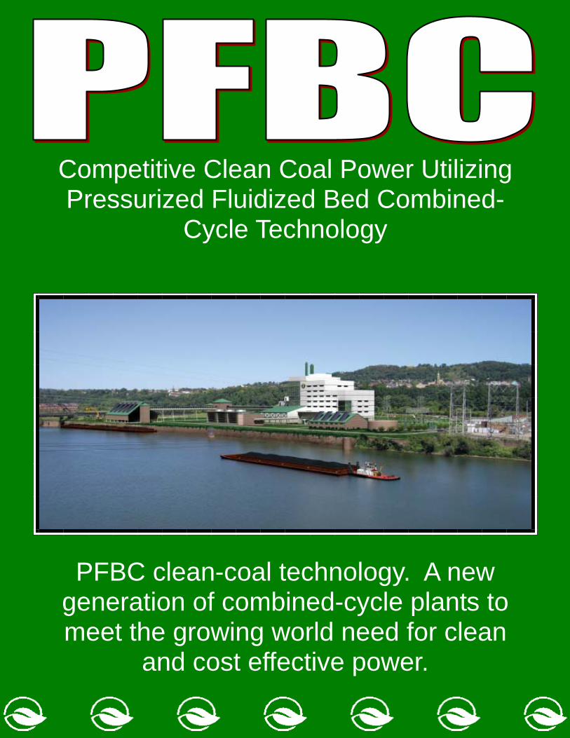
PFBC clean-coal technology. A new generation of combined-cycle plants to meet the growing world need for clean
and cost effective power.
Competitive Clean Coal Power Utilizing Pressurized Fluidized Bed Combined-
Cycle Technology

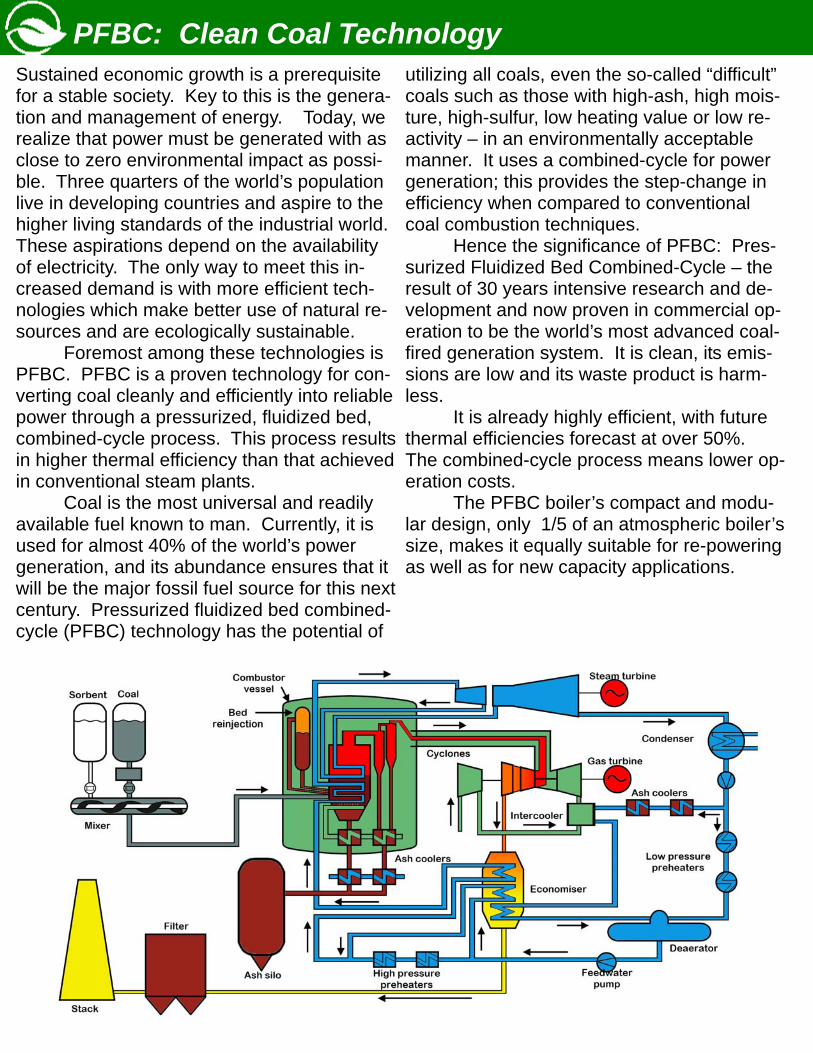
Sustained economic growth is a prerequisite for a stable society. Key to this is the genera-tion and management of energy. Today, we realize that power must be generated with as close to zero environmental impact as possi-ble. Three quarters of the world’s population live in developing countries and aspire to the higher living standards of the industrial world. These aspirations depend on the availability of electricity. The only way to meet this in-creased demand is with more efficient tech-nologies which make better use of natural re-sources and are ecologically sustainable. Foremost among these technologies is PFBC. PFBC is a proven technology for con-verting coal cleanly and efficiently into reliable power through a pressurized, fluidized bed, combined-cycle process. This process results in higher thermal efficiency than that achieved in conventional steam plants. Coal is the most universal and readily available fuel known to man. Currently, it is used for almost 40% of the world’s power generation, and its abundance ensures that it will be the major fossil fuel source for this next century. Pressurized fluidized bed combined-cycle (PFBC) technology has the potential of
utilizing all coals, even the so-called “difficult” coals such as those with high-ash, high mois-ture, high-sulfur, low heating value or low re-activity – in an environmentally acceptable manner. It uses a combined-cycle for power generation; this provides the step-change in efficiency when compared to conventional coal combustion techniques. Hence the significance of PFBC: Pres-surized Fluidized Bed Combined-Cycle – the result of 30 years intensive research and de-velopment and now proven in commercial op-eration to be the world’s most advanced coal-fired generation system. It is clean, its emis-sions are low and its waste product is harm-less. It is already highly efficient, with future thermal efficiencies forecast at over 50%. The combined-cycle process means lower op-eration costs. The PFBC boiler’s compact and modu-lar design, only 1/5 of an atmospheric boiler’s size, makes it equally suitable for re-powering as well as for new capacity applications.
PFBC: Clean Coal Technology
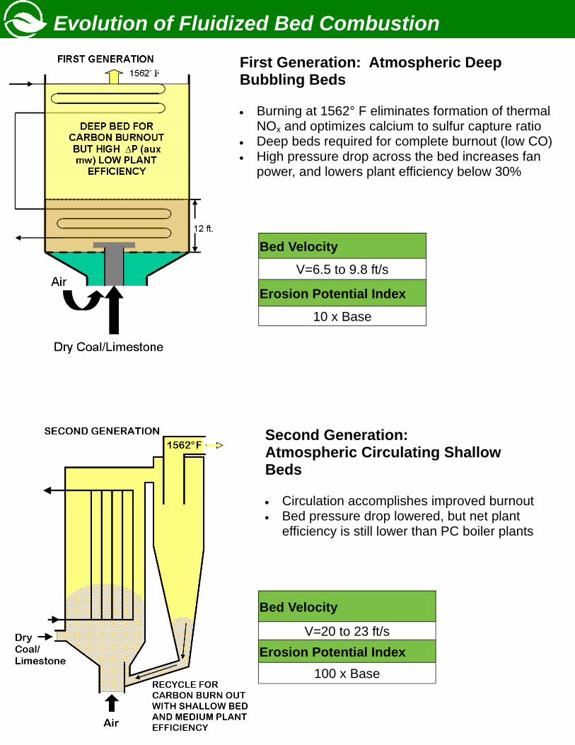
Bed Velocity V=6.5 to 9.8 ft/s
Erosion Potential Index
10 x Base
Bed Velocity
V=20 to 23 ft/s Erosion Potential Index
100 x Base
Evolution of Fluidized Bed Combustion
First Generation: Atmospheric Deep Bubbling Beds • Burning at 1562° F eliminates formation of thermal
NOx and optimizes calcium to sulfur capture ratio • Deep beds required for complete burnout (low CO) • High pressure drop across the bed increases fan
power, and lowers plant efficiency below 30%
Second Generation: Atmospheric Circulating Shallow Beds • Circulation accomplishes improved burnout • Bed pressure drop lowered, but net plant
efficiency is still lower than PC boiler plants
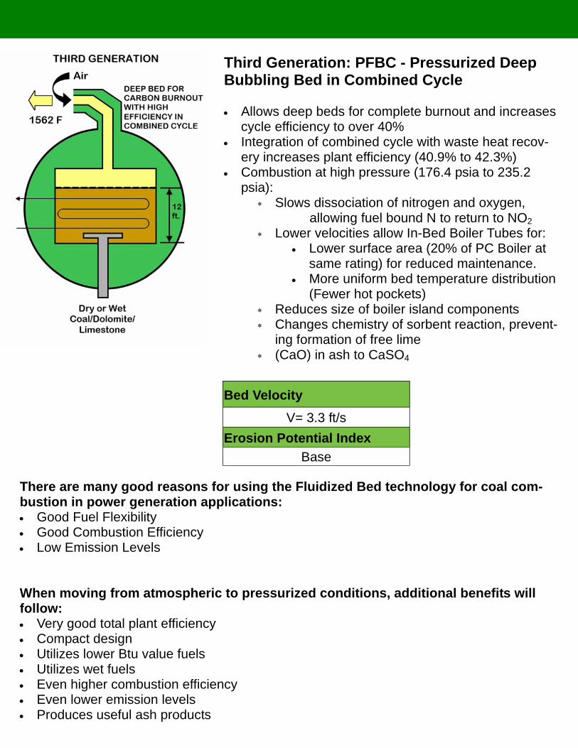
Bed Velocity V= 3.3 ft/s
Erosion Potential Index Base
Third Generation: PFBC - Pressurized Deep Bubbling Bed in Combined Cycle
• Allows deep beds for complete burnout and increases
cycle efficiency to over 40% • Integration of combined cycle with waste heat recov-
ery increases plant efficiency (40.9% to 42.3%) • Combustion at high pressure (176.4 psia to 235.2
psia): ∗ Slows dissociation of nitrogen and oxygen, allowing fuel bound N to return to NO2 ∗ Lower velocities allow In-Bed Boiler Tubes for:
• Lower surface area (20% of PC Boiler at same rating) for reduced maintenance.
• More uniform bed temperature distribution (Fewer hot pockets)
∗ Reduces size of boiler island components ∗ Changes chemistry of sorbent reaction, prevent-
ing formation of free lime ∗ (CaO) in ash to CaSO4
There are many good reasons for using the Fluidized Bed technology for coal com-bustion in power generation applications: • Good Fuel Flexibility • Good Combustion Efficiency • Low Emission Levels When moving from atmospheric to pressurized conditions, additional benefits will follow: • Very good total plant efficiency • Compact design • Utilizes lower Btu value fuels • Utilizes wet fuels • Even higher combustion efficiency • Even lower emission levels • Produces useful ash products
PFBC: The System and Its Components
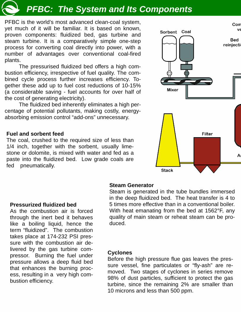
Fuel and sorbent feed The coal, crushed to the required size of less than 1/4 inch, together with the sorbent, usually lime-stone or dolomite, is mixed with water and fed as a paste into the fluidized bed. Low grade coals are fed pneumatically.
Pressurized fluidized bed As the combustion air is forced through the inert bed it behaves like a boiling liquid, hence the term “fluidized”. The combustion takes place at 174-232 PSI pres-sure with the combustion air de-livered by the gas turbine com-pressor. Burning the fuel under pressure allows a deep fluid bed that enhances the burning proc-ess, resulting in a very high com-bustion efficiency.
Steam Generator Steam is generated in the tube bundles immersed in the deep fluidized bed. The heat transfer is 4 to 5 times more effective than in a conventional boiler. With heat emanating from the bed at 1562°F, any quality of main steam or reheat steam can be pro-duced.
Cyclones Before the high pressure flue gas leaves the pres-sure vessel, fine particulates or “fly-ash” are re-moved. Two stages of cyclones in series remove 98% of dust particles, sufficient to protect the gas turbine, since the remaining 2% are smaller than 10 microns and less than 500 ppm.
PFBC is the world’s most advanced clean-coal system, yet much of it will be familiar. It is based on known, proven components: fluidized bed, gas turbine and steam turbine. It is a comparatively simple one-step process for converting coal directly into power, with a number of advantages over conventional coal-fired plants. The pressurised fluidized bed offers a high com-bustion efficiency, irrespective of fuel quality. The com-bined cycle process further increases efficiency. To-gether these add up to fuel cost reductions of 10-15% (a considerable saving - fuel accounts for over half of the cost of generating electricity). The fluidized bed inherently eliminates a high per-centage of potential pollutants, making costly, energy-absorbing emission control “add-ons” unnecessary.
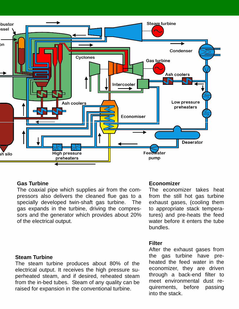
Gas Turbine The coaxial pipe which supplies air from the com-pressors also delivers the cleaned flue gas to a specially developed twin-shaft gas turbine. The gas expands in the turbine, driving the compres-sors and the generator which provides about 20% of the electrical output.
Steam Turbine The steam turbine produces about 80% of the electrical output. It receives the high pressure su-perheated steam, and if desired, reheated steam from the in-bed tubes. Steam of any quality can be raised for expansion in the conventional turbine.
Filter After the exhaust gases from the gas turbine have pre-heated the feed water in the economizer, they are driven through a back-end filter to meet environmental dust re-quirements, before passing into the stack.
Economizer The economizer takes heat from the still hot gas turbine exhaust gases, (cooling them to appropriate stack tempera-tures) and pre-heats the feed water before it enters the tube bundles.
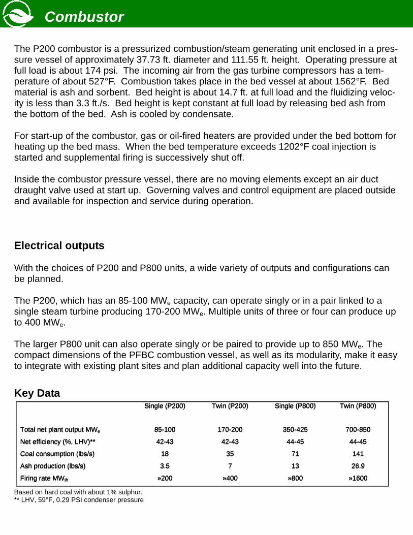
Combustor The P200 combustor is a pressurized combustion/steam generating unit enclosed in a pres-sure vessel of approximately 37.73 ft. diameter and 111.55 ft. height. Operating pressure at full load is about 174 psi. The incoming air from the gas turbine compressors has a tem-perature of about 527°F. Combustion takes place in the bed vessel at about 1562°F. Bed material is ash and sorbent. Bed height is about 14.7 ft. at full load and the fluidizing veloc-ity is less than 3.3 ft./s. Bed height is kept constant at full load by releasing bed ash from the bottom of the bed. Ash is cooled by condensate. For start-up of the combustor, gas or oil-fired heaters are provided under the bed bottom for heating up the bed mass. When the bed temperature exceeds 1202°F coal injection is started and supplemental firing is successively shut off. Inside the combustor pressure vessel, there are no moving elements except an air duct draught valve used at start up. Governing valves and control equipment are placed outside and available for inspection and service during operation.
Electrical outputs With the choices of P200 and P800 units, a wide variety of outputs and configurations can be planned. The P200, which has an 85-100 MWe capacity, can operate singly or in a pair linked to a single steam turbine producing 170-200 MWe. Multiple units of three or four can produce up to 400 MWe. The larger P800 unit can also operate singly or be paired to provide up to 850 MWe. The compact dimensions of the PFBC combustion vessel, as well as its modularity, make it easy to integrate with existing plant sites and plan additional capacity well into the future.
Key Data
Based on hard coal with about 1% sulphur. ** LHV, 59°F, 0.29 PSI condenser pressure
Single (P200) Twin (P200) Single (P800) Twin (P800)
Total net plant output MWe 85-100 170-200 350-425 700-850
Net efficiency (%, LHV)** 42-43 42-43 44-45 44-45
Coal consumption (lbs/s) 18 35 71 141
Ash production (lbs/s) 3.5 7 13 26.9
Firing rate MWth »200 »400 »800 »1600
Single (P200) Twin (P200) Single (P800) Twin (P800)
Total net plant output MWe 85-100 170-200 350-425 700-850
Net efficiency (%, LHV)** 42-43 42-43 44-45 44-45
Coal consumption (lbs/s) 18 35 71 141
Ash production (lbs/s) 3.5 7 13 26.9
Firing rate MWth »200 »400 »800 »1600
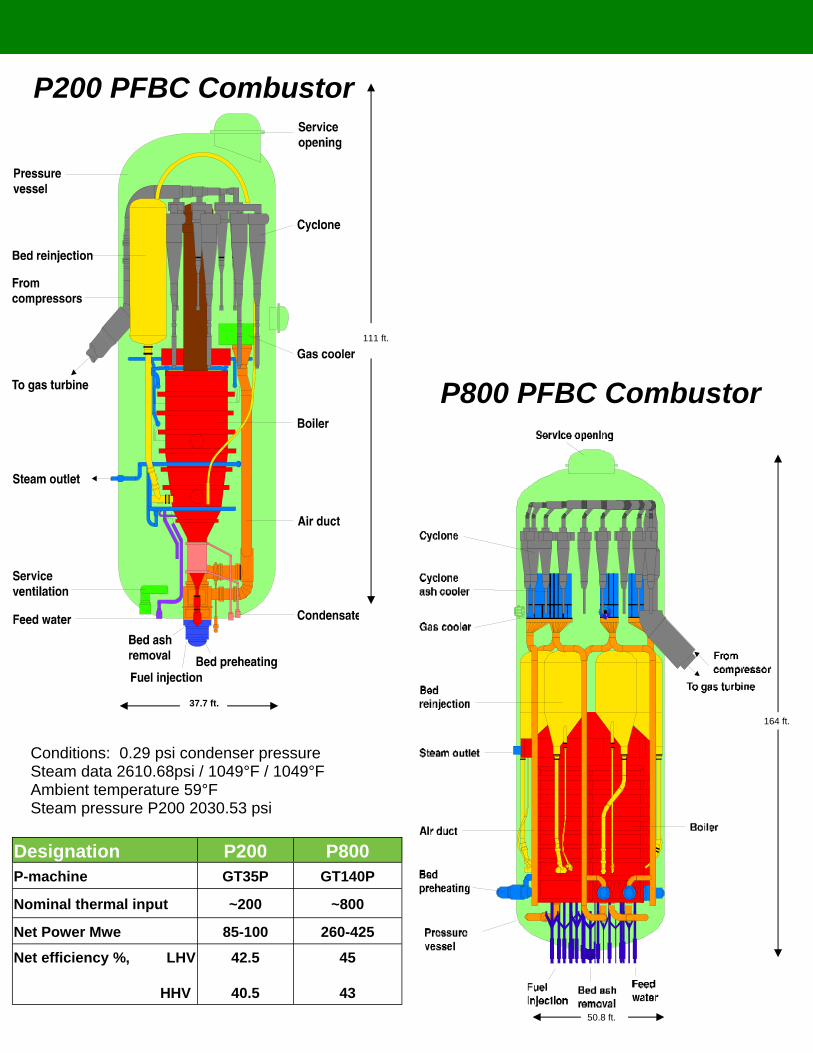
P800 PFBC Combustor
P200 PFBC Combustor
Designation P200 P800 P-machine GT35P GT140P
Nominal thermal input ~200 ~800
Net Power Mwe 85-100 260-425
Net efficiency %, LHV
HHV
42.5
40.5
45
43
Conditions: 0.29 psi condenser pressure Steam data 2610.68psi / 1049°F / 1049°F Ambient temperature 59°F Steam pressure P200 2030.53 psi
37.7 ft.
111 ft.
164 ft.
50.8 ft.
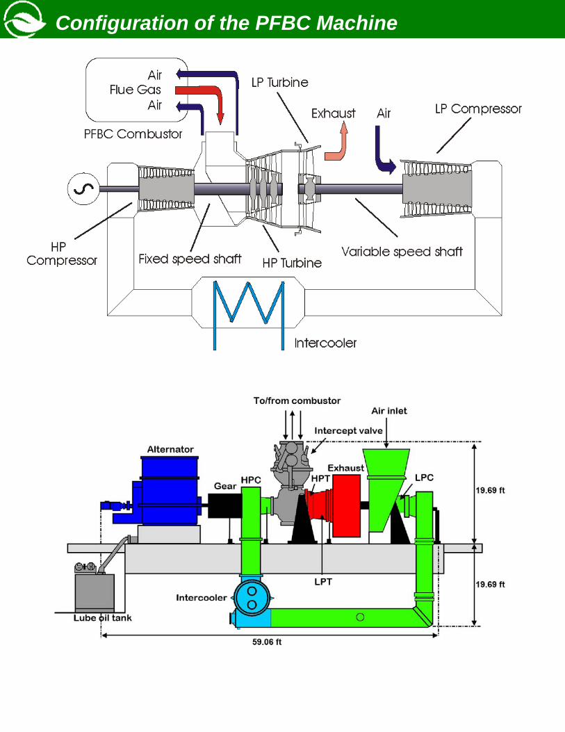
Configuration of the PFBC Machine
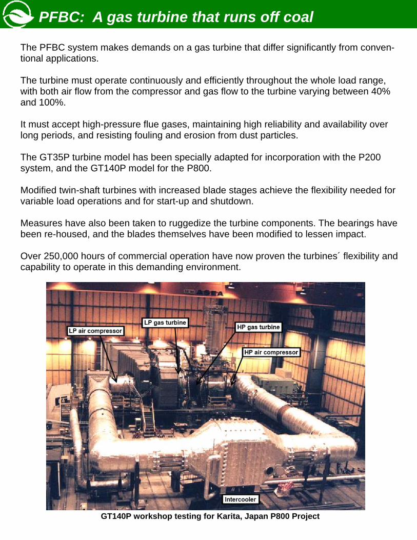
PFBC: A gas turbine that runs off coal
The PFBC system makes demands on a gas turbine that differ significantly from conven-tional applications. The turbine must operate continuously and efficiently throughout the whole load range, with both air flow from the compressor and gas flow to the turbine varying between 40% and 100%. It must accept high-pressure flue gases, maintaining high reliability and availability over long periods, and resisting fouling and erosion from dust particles. The GT35P turbine model has been specially adapted for incorporation with the P200 system, and the GT140P model for the P800. Modified twin-shaft turbines with increased blade stages achieve the flexibility needed for variable load operations and for start-up and shutdown. Measures have also been taken to ruggedize the turbine components. The bearings have been re-housed, and the blades themselves have been modified to lessen impact. Over 250,000 hours of commercial operation have now proven the turbines´ flexibility and capability to operate in this demanding environment.
GT140P workshop testing for Karita, Japan P800 Project
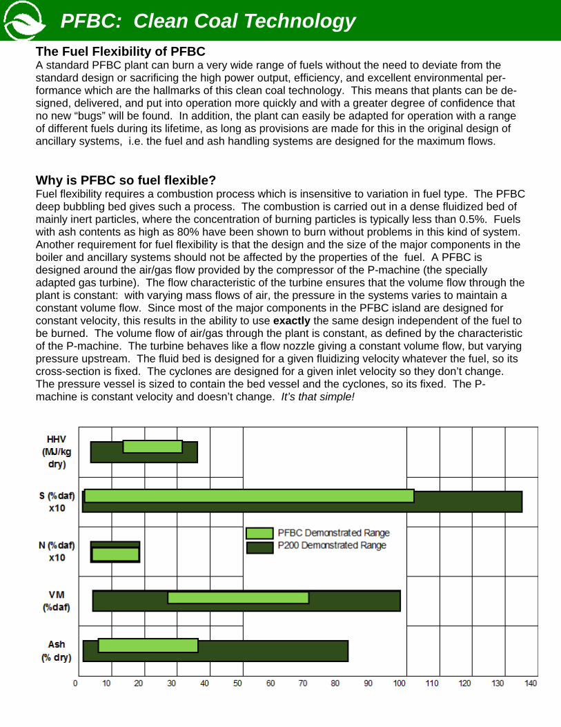
PFBC: Clean Coal Technology The Fuel Flexibility of PFBC A standard PFBC plant can burn a very wide range of fuels without the need to deviate from the standard design or sacrificing the high power output, efficiency, and excellent environmental per-formance which are the hallmarks of this clean coal technology. This means that plants can be de-signed, delivered, and put into operation more quickly and with a greater degree of confidence that no new “bugs” will be found. In addition, the plant can easily be adapted for operation with a range of different fuels during its lifetime, as long as provisions are made for this in the original design of ancillary systems, i.e. the fuel and ash handling systems are designed for the maximum flows. Why is PFBC so fuel flexible? Fuel flexibility requires a combustion process which is insensitive to variation in fuel type. The PFBC deep bubbling bed gives such a process. The combustion is carried out in a dense fluidized bed of mainly inert particles, where the concentration of burning particles is typically less than 0.5%. Fuels with ash contents as high as 80% have been shown to burn without problems in this kind of system. Another requirement for fuel flexibility is that the design and the size of the major components in the boiler and ancillary systems should not be affected by the properties of the fuel. A PFBC is designed around the air/gas flow provided by the compressor of the P-machine (the specially adapted gas turbine). The flow characteristic of the turbine ensures that the volume flow through the plant is constant: with varying mass flows of air, the pressure in the systems varies to maintain a constant volume flow. Since most of the major components in the PFBC island are designed for constant velocity, this results in the ability to use exactly the same design independent of the fuel to be burned. The volume flow of air/gas through the plant is constant, as defined by the characteristic of the P-machine. The turbine behaves like a flow nozzle giving a constant volume flow, but varying pressure upstream. The fluid bed is designed for a given fluidizing velocity whatever the fuel, so its cross-section is fixed. The cyclones are designed for a given inlet velocity so they don’t change. The pressure vessel is sized to contain the bed vessel and the cyclones, so its fixed. The P-machine is constant velocity and doesn’t change. It’s that simple!
Sample of Yearly Benefits of Increased Efficiency
PFBC: Increased Efficiency
Fuel Costs PFBC is fuel efficient, irrespective of coal quality or sulfur content. Many aspects of the system’s design con-tribute to this—above all, the com-bined-cycle process, which increases plant efficiency and reduces fuel costs by 10-15% compared to conventional coal technologies. In retrofit cases, the fuel savings could be over 20%.
PFBC gives 3-5% higher efficiency. 3% higher efficiency means: • 52,000 tons of coal saved • 3,500 tons less sorbent used • 10,000 tons less ash production • 1,000 tons less SO2 • 240 tons less NOx • 122,000 tons less CO2
Efficiency is a major point in any utility’s evaluation of power plant technologies. Before PFBC, coal generation was linked to a single steam cycle, which limited the op-portunity to reach high efficiencies. PFBC technology has made a breakthrough. The unique characteristic of this system is that it already yields high heat efficiencies with low gas turbine inlet temperatures. At around 1562°F, it is already approaching 45% net efficiency. PFBC attains these high levels through the use of a thermodynamic cycle, which very effectively combines the relatively low temperature but highly efficient gas turbine with a modern steam turbine. The use of the gas turbine also reduces the demand for auxiliary power, allowing more of the electricity generated to be delivered to users. In addition, by incorporating the tube bundles into the fluidized bed, the most ad-vanced steam conditions can be generated, improving the performance of the steam turbine. The combination of these developments and PFBC’s simplicity already make it a commercially attractive proposition. The conservative inlet temperatures for the gas turbine and the ability to reach the most advanced steam data open the way for in-creased operating temperatures and even higher thermal efficiencies in the future.
Assumptions • 350 MWe power plant • 40—45% efficiency increase • Coal: 1% sulfur, 15% ash, 10,000
BTUs • 6,000 hours per year
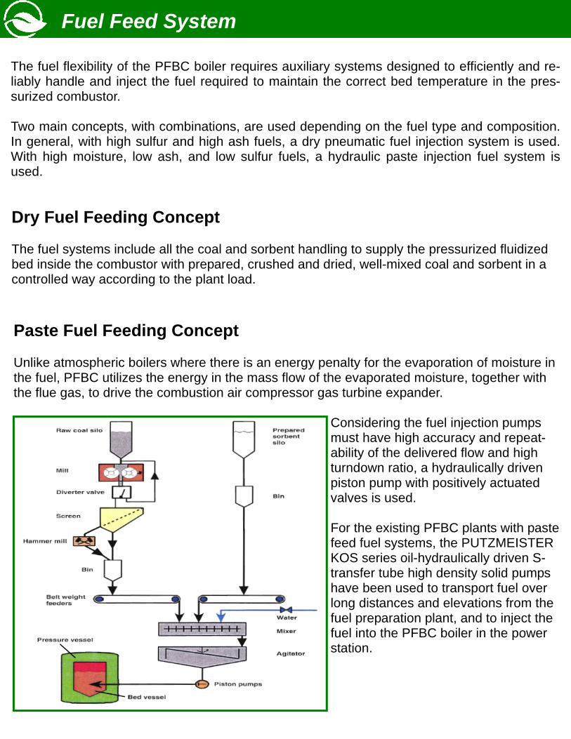
Fuel Feed System
The fuel flexibility of the PFBC boiler requires auxiliary systems designed to efficiently and re-liably handle and inject the fuel required to maintain the correct bed temperature in the pres-surized combustor. Two main concepts, with combinations, are used depending on the fuel type and composition. In general, with high sulfur and high ash fuels, a dry pneumatic fuel injection system is used. With high moisture, low ash, and low sulfur fuels, a hydraulic paste injection fuel system is used.
Paste Fuel Feeding Concept Unlike atmospheric boilers where there is an energy penalty for the evaporation of moisture in the fuel, PFBC utilizes the energy in the mass flow of the evaporated moisture, together with the flue gas, to drive the combustion air compressor gas turbine expander.
Considering the fuel injection pumps must have high accuracy and repeat-ability of the delivered flow and high turndown ratio, a hydraulically driven piston pump with positively actuated valves is used. For the existing PFBC plants with paste feed fuel systems, the PUTZMEISTER KOS series oil-hydraulically driven S-transfer tube high density solid pumps have been used to transport fuel over long distances and elevations from the fuel preparation plant, and to inject the fuel into the PFBC boiler in the power station.
Dry Fuel Feeding Concept The fuel systems include all the coal and sorbent handling to supply the pressurized fluidized bed inside the combustor with prepared, crushed and dried, well-mixed coal and sorbent in a controlled way according to the plant load.
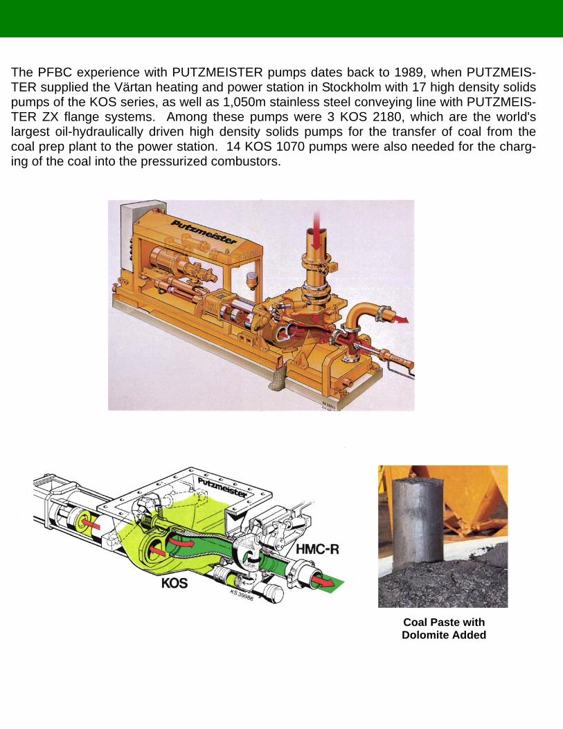
The PFBC experience with PUTZMEISTER pumps dates back to 1989, when PUTZMEIS-TER supplied the Värtan heating and power station in Stockholm with 17 high density solids pumps of the KOS series, as well as 1,050m stainless steel conveying line with PUTZMEIS-TER ZX flange systems. Among these pumps were 3 KOS 2180, which are the world's largest oil-hydraulically driven high density solids pumps for the transfer of coal from the coal prep plant to the power station. 14 KOS 1070 pumps were also needed for the charg-ing of the coal into the pressurized combustors.
Coal Paste with Dolomite Added
PFBC Ash Utilization
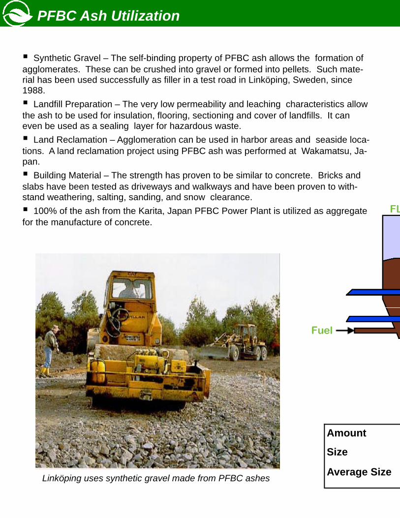
Linköping uses synthetic gravel made from PFBC ashes
Amount
Size
Average Size
Synthetic Gravel – The self-binding property of PFBC ash allows the formation of agglomerates. These can be crushed into gravel or formed into pellets. Such mate-rial has been used successfully as filler in a test road in Linköping, Sweden, since 1988.
Landfill Preparation – The very low permeability and leaching characteristics allow the ash to be used for insulation, flooring, sectioning and cover of landfills. It can even be used as a sealing layer for hazardous waste.
Land Reclamation – Agglomeration can be used in harbor areas and seaside loca-tions. A land reclamation project using PFBC ash was performed at Wakamatsu, Ja-pan.
Building Material – The strength has proven to be similar to concrete. Bricks and slabs have been tested as driveways and walkways and have been proven to with-stand weathering, salting, sanding, and snow clearance.
100% of the ash from the Karita, Japan PFBC Power Plant is utilized as aggregate for the manufacture of concrete.
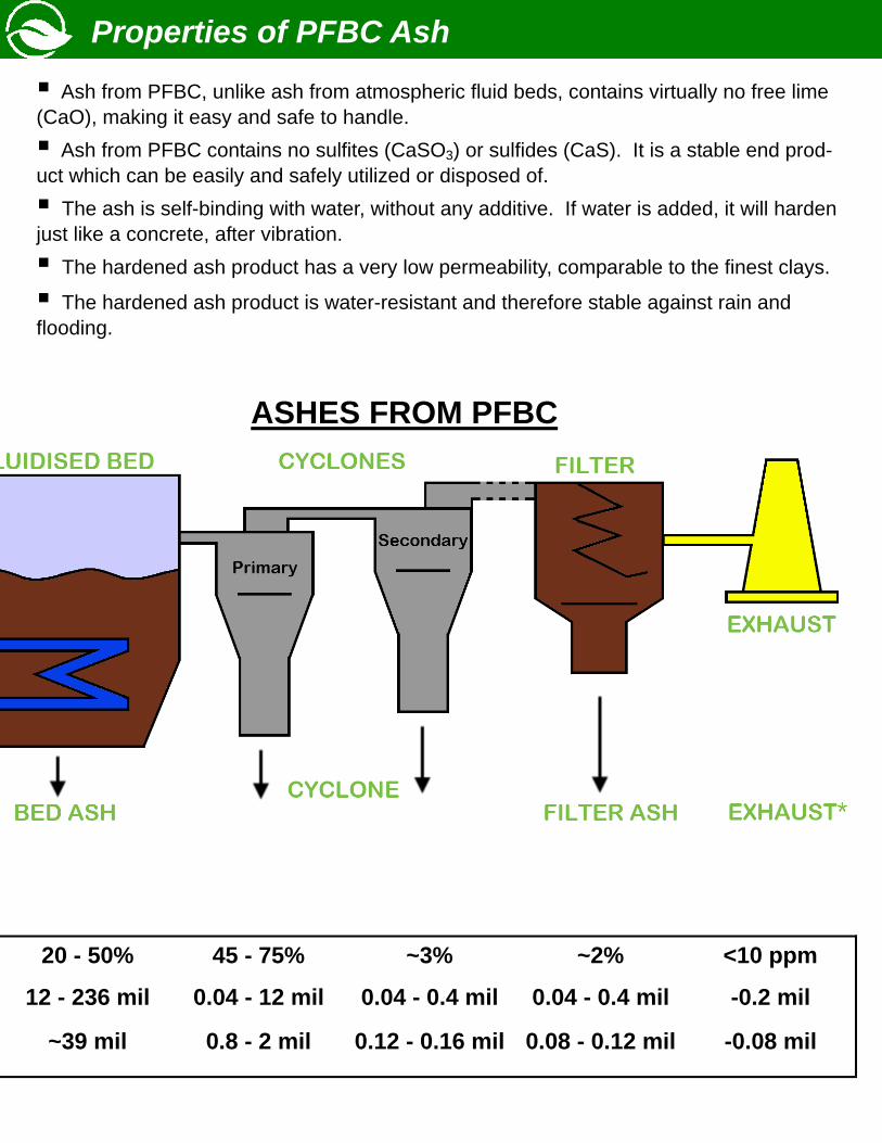
ASHES FROM PFBC
Properties of PFBC Ash
20 - 50% 45 - 75% ~3% ~2% <10 ppm
12 - 236 mil 0.04 - 12 mil 0.04 - 0.4 mil 0.04 - 0.4 mil -0.2 mil
~39 mil 0.8 - 2 mil 0.12 - 0.16 mil 0.08 - 0.12 mil -0.08 mil
Ash from PFBC, unlike ash from atmospheric fluid beds, contains virtually no free lime (CaO), making it easy and safe to handle.
Ash from PFBC contains no sulfites (CaSO3) or sulfides (CaS). It is a stable end prod-uct which can be easily and safely utilized or disposed of.
The ash is self-binding with water, without any additive. If water is added, it will harden just like a concrete, after vibration.
The hardened ash product has a very low permeability, comparable to the finest clays.
The hardened ash product is water-resistant and therefore stable against rain and flooding.
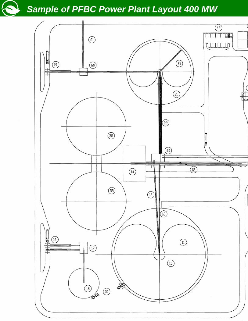
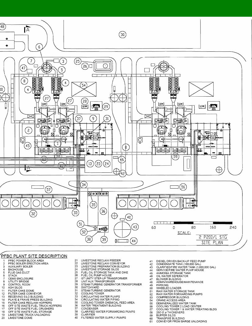
Sample of PFBC Power Plant Layout 400 MW
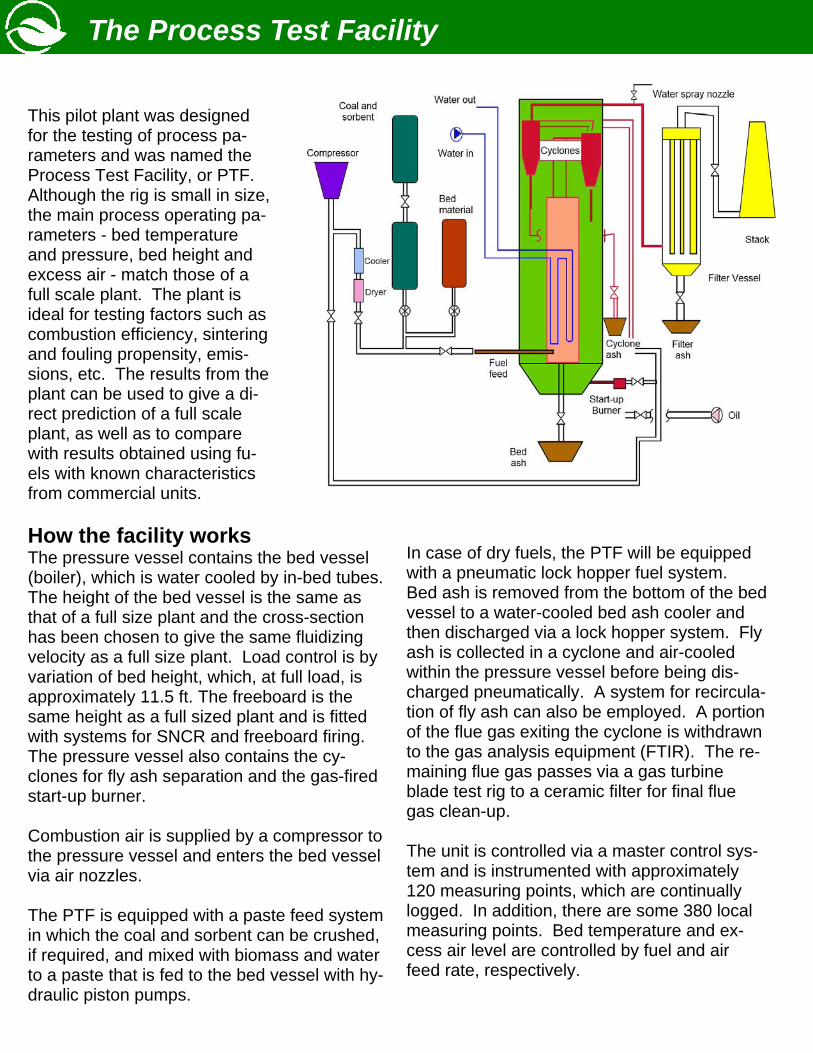
The Process Test Facility
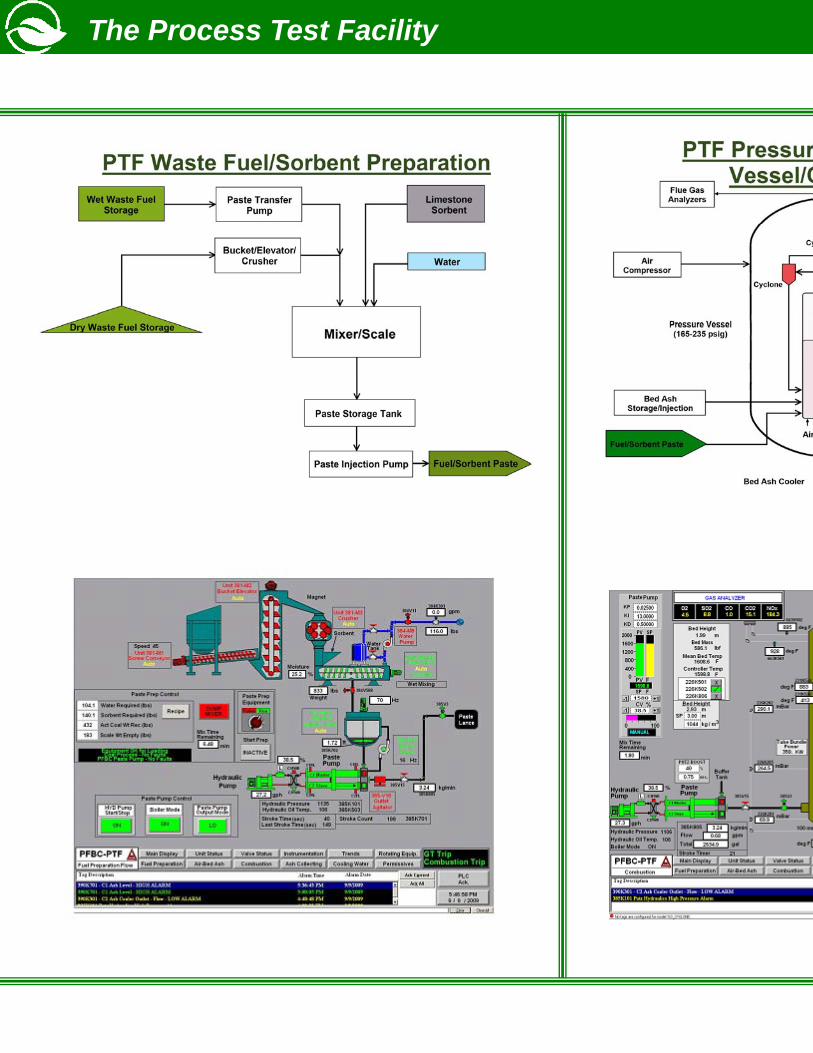
This pilot plant was designed for the testing of process pa-rameters and was named the Process Test Facility, or PTF. Although the rig is small in size, the main process operating pa-rameters - bed temperature and pressure, bed height and excess air - match those of a full scale plant. The plant is ideal for testing factors such as combustion efficiency, sintering and fouling propensity, emis-sions, etc. The results from the plant can be used to give a di-rect prediction of a full scale plant, as well as to compare with results obtained using fu-els with known characteristics from commercial units. How the facility works The pressure vessel contains the bed vessel (boiler), which is water cooled by in-bed tubes. The height of the bed vessel is the same as that of a full size plant and the cross-section has been chosen to give the same fluidizing velocity as a full size plant. Load control is by variation of bed height, which, at full load, is approximately 11.5 ft. The freeboard is the same height as a full sized plant and is fitted with systems for SNCR and freeboard firing. The pressure vessel also contains the cy-clones for fly ash separation and the gas-fired start-up burner. Combustion air is supplied by a compressor to the pressure vessel and enters the bed vessel via air nozzles. The PTF is equipped with a paste feed system in which the coal and sorbent can be crushed, if required, and mixed with biomass and water to a paste that is fed to the bed vessel with hy-draulic piston pumps.
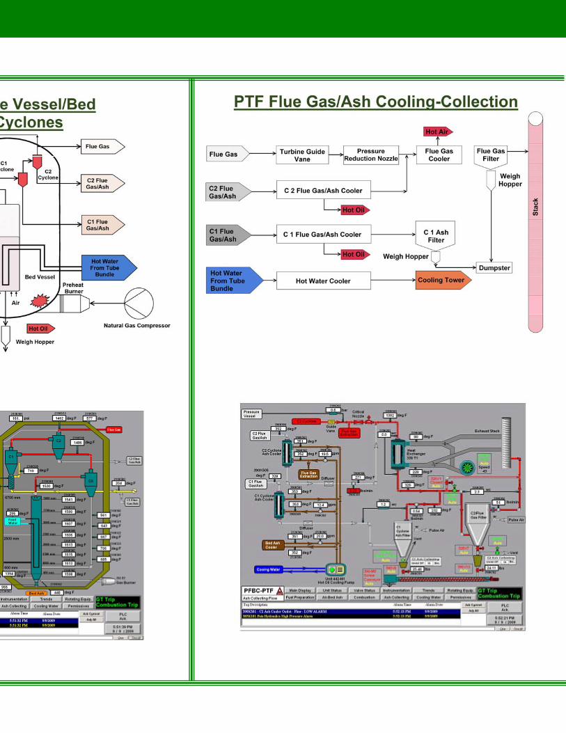
In case of dry fuels, the PTF will be equipped with a pneumatic lock hopper fuel system. Bed ash is removed from the bottom of the bed vessel to a water-cooled bed ash cooler and then discharged via a lock hopper system. Fly ash is collected in a cyclone and air-cooled within the pressure vessel before being dis-charged pneumatically. A system for recircula-tion of fly ash can also be employed. A portion of the flue gas exiting the cyclone is withdrawn to the gas analysis equipment (FTIR). The re-maining flue gas passes via a gas turbine blade test rig to a ceramic filter for final flue gas clean-up. The unit is controlled via a master control sys-tem and is instrumented with approximately 120 measuring points, which are continually logged. In addition, there are some 380 local measuring points. Bed temperature and ex-cess air level are controlled by fuel and air feed rate, respectively.
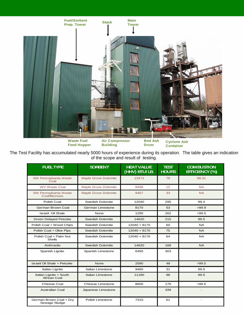
The Test Facility has accumulated nearly 5000 hours of experience during its operation. The table gives an indication of the scope and result of testing.
Fuel/SorbentPrep. Tower
MainTowerStack
Waste FuelFeed Hopper
Cyclone AshContainer
Bed AshDrum
Air CompressorBuilding
FUEL TYPE SORBENT HEAT VALUE (HHV) BTU/LB.
TEST HOURS
COMBUSTION EFFICIENCY (%)
SW Pennsylvania Waste Coal
Maple Grove Dolomite 13472 78 98.31
WV Waste Coal Maple Grove Dolomite 9498 12 NA
SW Pennsylvania Waste Coal/Biomass
Maple Grove Dolomite 9467 33 NA
Polish Coal Swedish Dolomite 12040 295 99.4
German Brown Coal German Limestone 8170 53 >99.9
Israeli Oil Shale None 1290 262 >99.5
Green Delayed Petcoke Swedish Dolomite 14620 215 99.5
Polish Coal + Wood Chips Swedish Dolomite 12040 + 8170 60 NA
Polish Coal + Olive Pips Swedish Dolomite 12040 + 8170 75 NA
Polish Coal + Palm Nut Shells
Swedish Dolomite 12040 + 8170 64 NA
Anthracite Swedish Dolomite 14620 168 NA
Spanish Lignite Spanish Limestone 6450 303
Israeli Oil Shale + Petcoke None 2580 48 >99.5
Italian Lignite Italian Limestone 9460 31 99.5
Italian Lignite + South African Coal
Italian Limestone 11180 98 99.5
Chinese Coal Chinese Limestone 8600 176 >99.5
Australian Coal Japanese Limestone 339 -
German Brown Coal + Dry Sewage Sludge
Polish Limestone 7310 61 -
The Process Test Facility
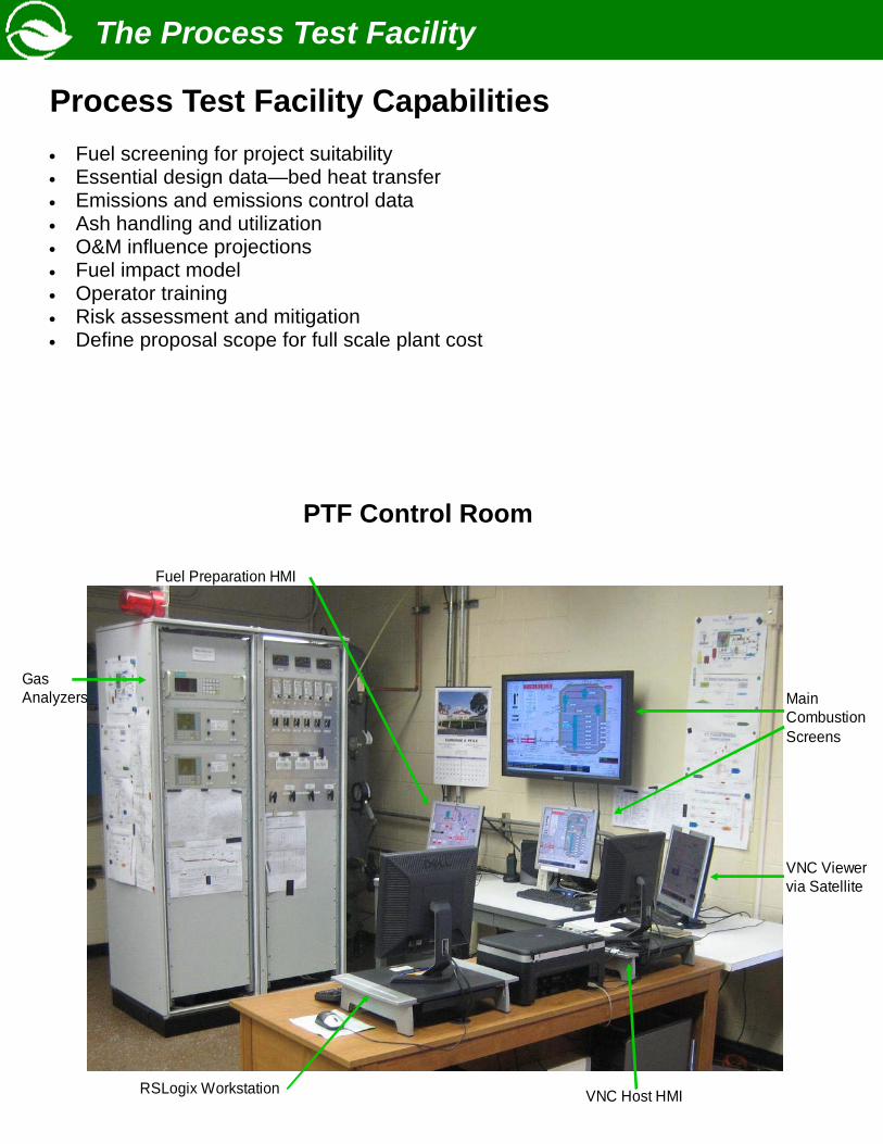
PTF Control Room
Main Combustion Screens
RSLogix Workstation VNC Host HMI
VNC Viewer via Satellite
GasAnalyzers
Fuel Preparation HMI
The Process Test Facility
Process Test Facility Capabilities • Fuel screening for project suitability • Essential design data—bed heat transfer • Emissions and emissions control data • Ash handling and utilization • O&M influence projections • Fuel impact model • Operator training • Risk assessment and mitigation • Define proposal scope for full scale plant cost
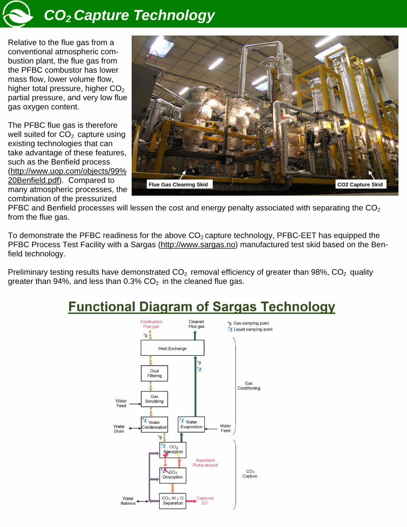
CO2 Capture Technology Relative to the flue gas from a conventional atmospheric com-bustion plant, the flue gas from the PFBC combustor has lower mass flow, lower volume flow, higher total pressure, higher CO2 partial pressure, and very low flue gas oxygen content. The PFBC flue gas is therefore well suited for CO2 capture using existing technologies that can take advantage of these features, such as the Benfield process (http://www.uop.com/objects/99%20Benfield.pdf). Compared to many atmospheric processes, the combination of the pressurized PFBC and Benfield processes will lessen the cost and energy penalty associated with separating the CO2 from the flue gas. To demonstrate the PFBC readiness for the above CO2 capture technology, PFBC-EET has equipped the PFBC Process Test Facility with a Sargas (http://www.sargas.no) manufactured test skid based on the Ben-field technology. Preliminary testing results have demonstrated CO2 removal efficiency of greater than 98%, CO2 quality greater than 94%, and less than 0.3% CO2 in the cleaned flue gas.
Flue Gas Cleaning Skid CO2 Capture Skid
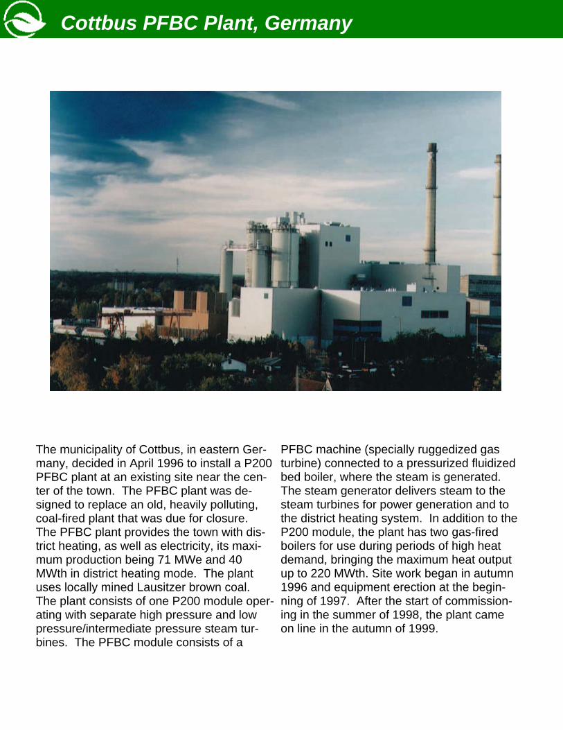
The municipality of Cottbus, in eastern Ger-many, decided in April 1996 to install a P200 PFBC plant at an existing site near the cen-ter of the town. The PFBC plant was de-signed to replace an old, heavily polluting, coal-fired plant that was due for closure. The PFBC plant provides the town with dis-trict heating, as well as electricity, its maxi-mum production being 71 MWe and 40 MWth in district heating mode. The plant uses locally mined Lausitzer brown coal. The plant consists of one P200 module oper-ating with separate high pressure and low pressure/intermediate pressure steam tur-bines. The PFBC module consists of a
PFBC machine (specially ruggedized gas turbine) connected to a pressurized fluidized bed boiler, where the steam is generated. The steam generator delivers steam to the steam turbines for power generation and to the district heating system. In addition to the P200 module, the plant has two gas-fired boilers for use during periods of high heat demand, bringing the maximum heat output up to 220 MWth. Site work began in autumn 1996 and equipment erection at the begin-ning of 1997. After the start of commission-ing in the summer of 1998, the plant came on line in the autumn of 1999.
Cottbus PFBC Plant, Germany
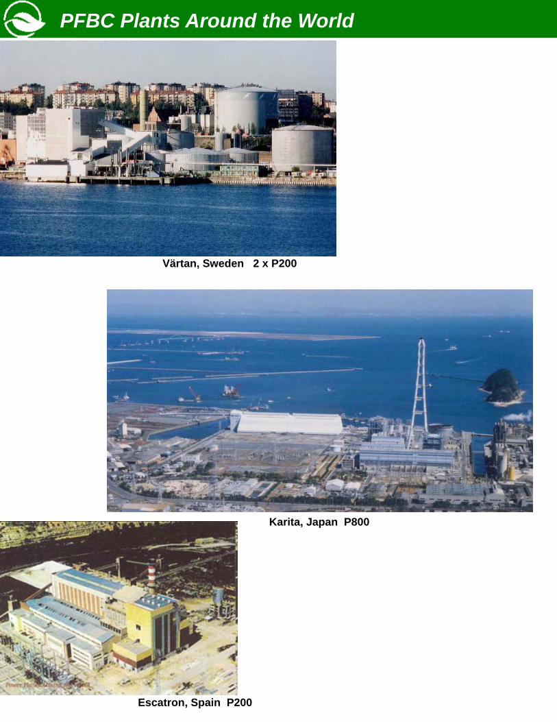
PFBC Plants Around the World
Karita, Japan P800
Värtan, Sweden 2 x P200
Escatron, Spain P200

PFBC Environmental Energy Technology, Inc. 1200 Maronda Way, Suite 400 Monessen, PA 15062’ (724) 684 - 4844