Embed Size (px)
Citation preview
ENERGY RECOVERY AND THERMAL DISPOSAL OF WASTES UTILIZING FLUIDIZED BED
REACTOR SYSTEMS
WILLIAM TRETHAWAY Copeland Systems Inc.
Oak Brook, IIIinoi5
INTRODUCTION
As the cost of energy accelerated these past few years, most fluid bed commercial incineration plants built include waste heat boilers for steam generation or recuperators to preheat the fluidizing combustion air for greater thermal efficiency.
The purpose of this paper is to review briefly the development and use of fluid bed technology for thermal oxidation of industrial wastes, and also to explore its potential utilization in other areas, specifically those involving solid wastes, and the recovery of energy from such waste sources. Most importantly and hopefully, the discussion will stimulate your thinking about a potential solution to solid waste processing.
During the relatively short period that fluidized bed technology has been available as an industrial process, a multitude of uses have been proposed. Many of these were ill-conceived and doomed to failure because available design and operation knowledge was too limited to permit optimum use. In spite of the many false starts, fluidized-solids technology has now been firmly established as a useful and valuable industrial unit operation. The petroleum and metallurgical industries have illustrated the potential importance and use of fluidized bed systems. Development has taken many years for fruition, but many new applications are now being extensively explored, particularly in the field of pollution control, where use of incineration is to be considered.
The use of fluidized-solids technology for industrial waste treatment is of relatively recent origin. Utilization of the technique for nuclear waste treatment perhaps has given impetus to development in the general waste treatment field. Certainly, successful application of this technique in treating and destroying pulping mill waste effluents has greatly accelerated present interest.
The purpose of this paper is to review .
the development and use of fluidized-solids technology in several industrial waste applications and also to explore its potential utilization in other areas. In many of these, use of fluidized-solids methods represents a simple, efficient, and economic approach to the solution of many of our industrial waste and pollution control problems.
BASIC FEATURES OF FLUID BED INCINERATION
The high thermal efficiency of the fluid bed incinerator provides total combustion of organic material in waste flows with low heating values or those too dilute to combust in conventional incinerators.
117
In many cases, combusv;on is autogenous, saving the continued cost of fuel associated with other methods of incineration.
Fluid bed efficiency is related to the following basic features:
1. Enormous surface area on which the combustion process can take place. (Approximately
LIQUID WASTE FE ED -----..,
, . . .
, " . . � . . . •
EXHAUST GASES
ENTRAIN ED MATERIAL 1:1-_ /1.1', � " . . , , - . " . '
� ... . ' . . FEED SPRAY DISPERSION It-c---..f-.'-:· . ... .'., . '
R EACTION VESSE L
DILUTE PHASE FLUIDIZED B E D
DENSE PHASE FLUIDIZED BED
SOLID PRODUCT
•
' . -� . '- CYCLONE EPARATOR
D UST RETURN
ORIFICE PLATE
------ FLUIDIZING GAS
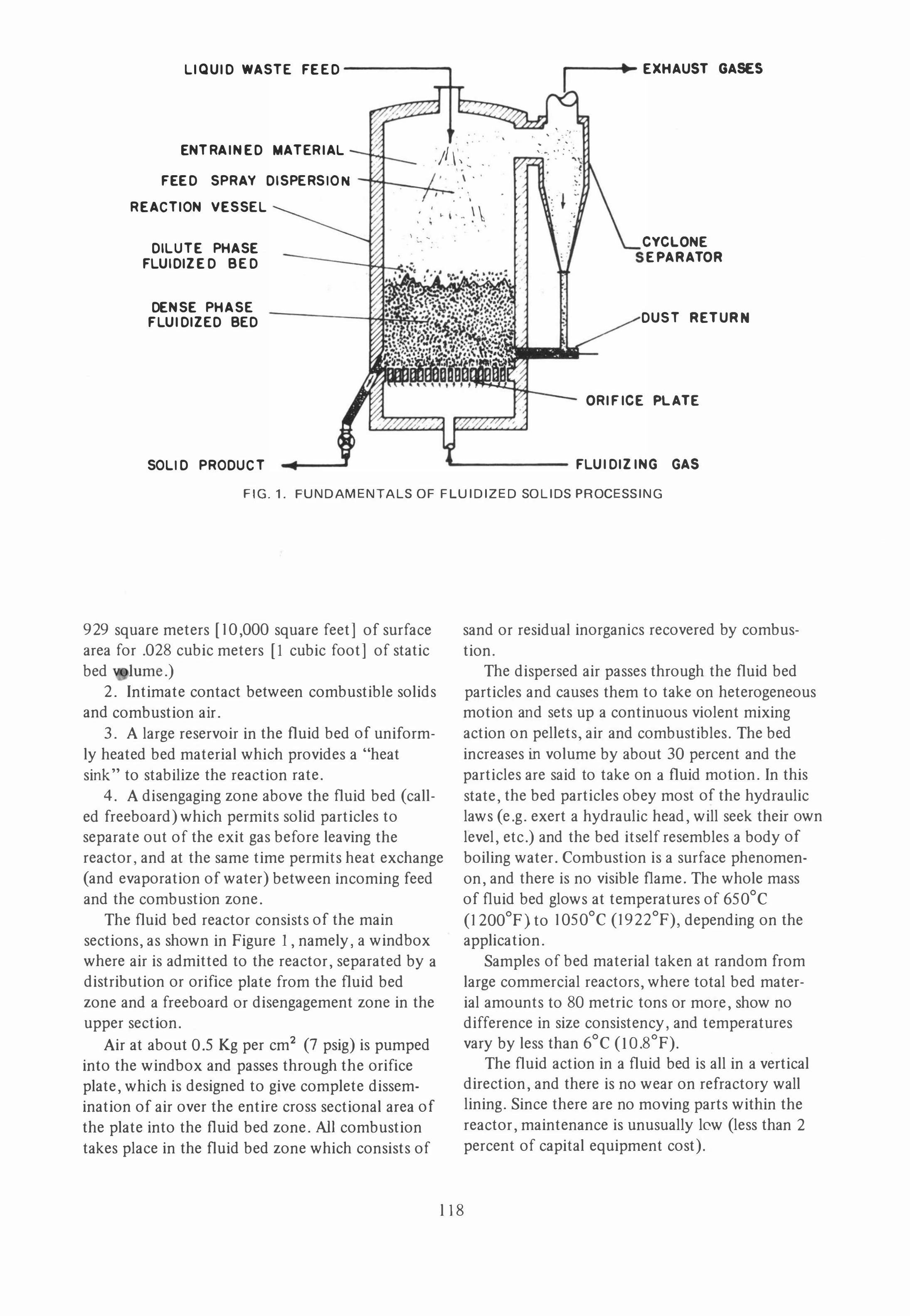
FIG.1. FUNDAMENTALS OF FLUIDIZED SOLIDS PROCESSING
929 square meters [10,000 square feet] of surface area for .02S cubic meters [I cubic foot] of static bed .)
2. Intimate contact between combustible solids and combustion air.
3. A large reservoir in the fluid bed of uniformly heated bed material which provides a "heat sink" to stabilize the reaction rate,
4, A disengaging zone above the fluid bed (called freeboard) which permits solid particles to separate out of the exit gas before leaving the reactor, and at the same time permits heat exchange (and evaporation of water) between incoming feed and the combustion zone,
The fluid bed reactor consists of the main sections, as shown in Figure I , namely, a wind box where air is admitted to the reactor, separated by a distribution or orifice plate from the fluid bed zone and a freeboard or disengagement zone in the upper section,
Air at about 0.5 Kg per cm2 (7 psig) is pumped into the wind box and passes through the orifice plate, which is designed to give complete dissemination of air over the entire cross sectional area of the plate into the fluid bed zone. All combustion takes place in the fluid bed zone which consists of
sand or residual inorganics recovered by combustion.
The dispersed air passes through the fluid bed particles and causes them to take on heterogeneous motion and sets up a continuous violent mixing action on pellets, air and combustibles. The bed increases in volume by about 30 percent and the particles are said to take on a fluid motion. In this state, the bed particles obey most of the hydraulic laws (e.g. exert a hydraulic head, will seek their own level, etc,) and the bed itself resembles a body of boiling water. Combustion is a surface phenomenon, and there is no visible flame, The whole mass of fluid bed glows at temperatures of 650°C (1200°F) to 1050°C (1922°F), depending on the applica tion.
Samples of bed material taken at random from large commercial reactors, where total bed material amounts to SO metric tons or more, show no difference in size consistency, and temperatures vary by less than 6°C (IO,SOF), .
The fluid action in a fluid bed is all in a vertical direction, and there is no wear on refractory wall lining. Since there are no moving parts within the reactor, maintenance is unusually low (less than 2 percent of capital equipment cost).
lIS
Steam recovery is achieved through the use of waste heat boilers.
The off-gas is always scrubbed before it is admitted to the atmosphere. Typical scrubbing equipment includes wetted-wall venturi scrubbers, spray type scrubbers, turbulent contact scrubbers and others. The scrubbed off-gas will pass air pollution codes.
The final product from the reactor system is either a recovered chemical or an inert ash, depending upon the application. Recovered chemicals are in their fully oxidized state while incinerator ash is a dry, inert, odorless dust of greatly reduced volume, that is easily handled for disposal.
FEED SYSTEMS
Since the variety of waste materials to be handled in a fluidized bed oxidation system can vary greatly, a corresponding variety of methods for feeding these materials into the fluidized bed reactor is needed.
If a sweeping generalization can be made, then it would be accurate to say that virtually any material handling system can be adapted to feed a fluidized bed reactor in order to accommodate the waste material under consideration.
The most common type of waste treated in fluidized bed systems is either liquid, semiliquid or solid.
Liquid wastes can usually be very well handled by centrifugal pumps, although liquids with unusual characteristics, such as high foaming tendency, viscosity or volatility will require more specialized pumps. The pOint of feed introduction into the fluidized bed reactor is usually chosen based upon the volatility and heating value of the • liquid. Liquids with low volatility and high water content such as spent pulping liquors are advantageously handled by a single feed gun, entering through the top of the fluidized bed reactor and spraying downward through the freeboard zone towards the fluidized bed. This method has many similarities with a spray dryer because of the counter-current flow of the wet liquid against the hot oxidation gases rising from the fluidized bed. As the feed material droplets dry the remaining solids drop into the fluidized bed to be oxidized.
Liquids with high volatility and lesser water content such as spent solvents or spent caustic solutions are more advantageously injected into the, fluidized bed directly through multiple feed ports ,
119
connected to a manifold around the periphery of the reactor.
The same distinction between freeboard feed and feeding into the bed of the reactor holds true for sludges. Highly volatile sludges such as API separator sludge from oil refineries are best fed directly into the bed, whereas very wet sludges such as waste activated sludge are best fed through the freeboard. Where the viscosity and shear resistance of the sludge permits, progressive cavity or positive displacement pumps are highly successful, where heavier sludges are better handled by conveyors and screw feeders or pneumatic conveying systems. Dewatered sludges from clarifier underflows are successfully being handled with pneumatic conveying systems at dry solids concentration of 30 percent and up.
Finally in feeding solid materials, belt conveyors, drag chain conveyors and pneumatic feeders are most successful. While screw feeders generally feed into the fluidized bed directly, pneumatic conveying systems discharge into the freeboard slightly above the fluidized bed. Particle size and uniformity of the material will be of great influence in the choice of the feeding system selected. Screw feeders will require greater uniformity of the material, which also should not be too compressible or too large in size. A pneumatic conveying system on the other hand can handle material which is quite nonuniform and as large as 5 x 5 x 15.24 cms (2 x 2 x 6 inches). An example of such a material is hammer-milled solid waste or municipal refuse.
Since energy requirements, capital cost and maintenance cost considerations are related to size to which solid waste is reduced, it appears that reduction to 30 cm (12 inches) is optimum. Conveyors can readily handle such reduced sized material, and fed into the reactor through a hanging chain when balanced draft systems are employed.
THERMAL EFFICIENCY
In contrast to conventional waste combustion methods fluidized bed oxidation has several inherent characteristics which result in greater thermal efficiency. Regardless of the fact that the operating temperature in a fluidized bed system can be varied over a wide range in order to suit the material processed or optimize heat utilization, the process is purely one of thermal oxidation in the absence of a flame. Fluidized bed systems commonly
operate substantially belQw flame temperature and thf;!refore require much lower heat input because there is no concern for flame stability.
Most systems can operate without auxiliary fuel by operating at a temperature at which the heating value of the waste material will be adequate to maintain the oxidation temperature while evaporating large quantities of associated water. This is ' particularly true in systems utilizing the top or freeboard feeding mechanism, which evaporates' most of the water in the freeboard of the reactor and lowers the temperature of the exhaust gases by over 100°C (212°F).
.
The weight of bed material in an average sized fluidized bed reactor may be between 11 and 66 metric tons (10-60 short tons) and this volume of hot material represents a substantial heat sink. Variations in feed rate, heating value of the waste can therefore be tolerated without upsetting the operation.
The tremendously large surface area in the fluidized bed available for gas to solids contact also permits operation at extremely low excess air rates. Systems are in operation in which the oxygen content of the exhaust gases is down to 1 percent by volume or less.
Despite operations at often very low temperature and low excess air the rate of burn-out is complete except under the most unusual conditions. The ash from fluidized bed combustion systems is totally inert in its fully oxidized state and contains no residual organic material.
The thermal efficiency of fluidized bed system can further be improved by conventional means such as using gas to air heat exchangers to preheat combustion air. More unusual is the application of techniques lending themselves especially well to fluidized bed reactors such as staging or fluidized bed feeding. With these methods the feed material can be preheated or dried to conserve heat, or the ash can be cooled by the combustion air in a fluidized bed cooler, which returns heat to the process. Combining such techniques into a three stage reactor can improve fuel economy by as much as 30 percent in many systems.
GASEOUS EMISSIONS AND PARTICULATES
In the combustion of any waste materials containing sulfur, phosphorous, nitrogen or halides, gaseous products of combustion form which are considered air pollutants if emitted from the combustion system. Unless countermeasures are taken,
S02 ,P2 Os ,Hel, HF, NOx and potentially others will be discharged from waste combustion processes.
Typical examples of the sources of the gaseous pollutants found in waste incineration systems are HCI from plastic materials like PVC, HF from fluorinated propellants in aerosol containers, S02 from acid sludges in chemical manufacturing and NOx from liquid waste generated during explosives manufacture.
Fluidized bed systems have several peculiar capabilities over conventional combustion systems which can be put to use to eliminate air pollution without creating water pollution.
There are many situations of course where the amount of a specific pollutant is so large as to justify its specific recovery for reuse. In such systems combustion is followed by absorption sytems for S02, such as from spent pulping liquor system; or HCl from steel pickling liquor disposal. In many situations, however, the recovery of specific chemicals is not possible or justified because of concentrations which are too low or exhaust gas streams consisting of an unwieldy mixture of different chemicals.
120
In systems where such gaseous pollutants are generated which exceed permisSible concentration under increasingly tightening government standards, it will become necessary to prevent the emission of these gaseous pollutants. This can be accomplished in several ways. A common one is the absorption of the pollutant in a wet scrubber, with the aid of alkaline absorbents not only to capture the pollutant, but also to prevent rapid corrosion of the wet scrubbing equipment. When ammonia or sodium hydroxide are used for this purpose, the scrubber effluent can easily create a water pollution problem. When using calcium hydroxide as the absorbent, however, the most common byproduct is a solid waste disposal problem, gypsum.
An alternate and very practical method of avoiding these latter two problems is to add the absorbent to the waste prior to feeding into the fluidized bed oxidation system. During the oxidation process the acidic pollutants will react with the alkaline absorbent to form fully oxidized salts. By addiong lime to an acid sludge, for example, a pelletized dry byproduct of calcium sulfate can be formed during fluidized bed oxidation. By using a slight excess of alkali the emissions of S02 will be minimal.
In a similar fashion gaseous pollutants could be absorbed in a wet scrubbing system, which is
being neutralized with an alkaline material, but in order to avoid having a water pollution problem the scrubber effluent can be injected into the fluidized bed oxidation unit for disposal by evaporation and pelletization of the salt formed in the wet scrubber. The salt then becomes a portion of the ash discharged from the combustion system.
Nitrous oxides are formed in virtually all combustion systems for atmospheric nitrogen and oxygen, favored reactions, of course, are enhanced by the presence of nitrates or ammonia found in waste streams. The operating temperatures in fluidized bed oxidation systems as well as the excess air rates, however, are so low as to red uce the formation of NOx to an absolute minimum. Even during the pilot plant �dation of nitrate containing wastes in a fluidized bed system the formation of NOx was so low that it did not exhibit the typical brown haze associated with such processes in commercial operation.
Particulates can be readily handled in a wet scrubber system following the heat recovery equipment. Kleinau gives specific values (1] in his paper "Environmental Impact of Fluidized Bed Combustion Systems."
Because of the significant capital investment requirements for electrostatic precipitators, all of the designs proposed to date have employed wet scrubbers with an alkaline medium.
PROVEN APPLICATIONS
As was cited in the introduction of this paper, thermal oxidation of wastes using fluid bed technology has only been commercialized in the last 14 years. During most of that era, tremendous strides in technology have broadened the applications into many industrial and into some municipal waste disposal problems. While it is true that much of the developed technology has been directed toward the solution of industrial liquid waste problems, in the latter part of the era cited, additional applications in the solid waste segment of total waste incineration have made significant strides also. Yes, we are still in the infancy of this technological development, but the inherent potentials which can accrue to everyone in the form of resource and energy recovery from solid waste processing, require that we explore those possibilities which are available and develop this resource, not problem, to all mankind's benefit.
At this Conference we are discussing solid waste processing, and in particular, this author is present-
ing information concerning processing of solid waste in fluid bed reactors to recovery energy therefrom. Therefore, I wish to cite literature only concerning past developments for the interested reader, and then proceed with recent developments and the future potential of fluid bed incinerators in processing solid waste.
Hanway and Wheeler [2] discussed chemical and energy recovery utilizing fluid bed reactors for incineration of spent sulfite liquor from mills employing magnesia base pulping.
Po Man Wong discussed primary treatment of newsprint mill effluent including solid waste incin-• eration in a fluid bed reactor [3].
Copeland discussed the design and operation of fluid bed incinerators for solid and liquid wastes [4].
Limerick reported on solid waste and sludge • incineration in fluid bed reactors at Great Lakes Paper Company, Thunder Bay, Ontario, Canada [5]. It is at this installation tha t several "firsts" in fluid bed technology are employed which warrant further discussion.
The fluid bed incinerator was designed to process primary effluent sludge, wood rejects, bark and various wood debris at a rate of 137.5 metric tons per day (125 short tons per day) dry solids with a weighted average moisture content of 70 percent. Under these conditions, autogenous combustion take place at temperatures in excess of 760°C (l400°F).
As reported by Limerick, bark and wood debris were reduced iIi size to 5 x 5 x 15.24 centimeters (2 x 2 x 6 inches) by a hammer-mill. The size reduced waste was conveyed pneumatically into the fluid bed incinerator. After a few months of operations, the cost of resurfacing hammers and replacement of hammers became prohibitively expensive. Rocks, gravel and tramp metal which accompanied bark retrieved from their storage pile was causing excessive wear on the hammers.
. It was agreed that an alternate feeding system was required which could accept the solid waste without pretreatment.
121
The principle design criteria for the new feed system was that it would be required to accept logs up to one meter (3.3 feet) in length, because some wood received by the mill is unsuitable for manufacturing pulp.
A rotary feeder with hyrdaulic drive was designed and installed in the side of the fluid bed reactor near the dome. It was designed to accept a one meter (3.3 foot) log. The blower from the previously used pneumatic feeder was used to air pad the
•
rotary feeder and protect the feeder from the temperatures inside the reactor.
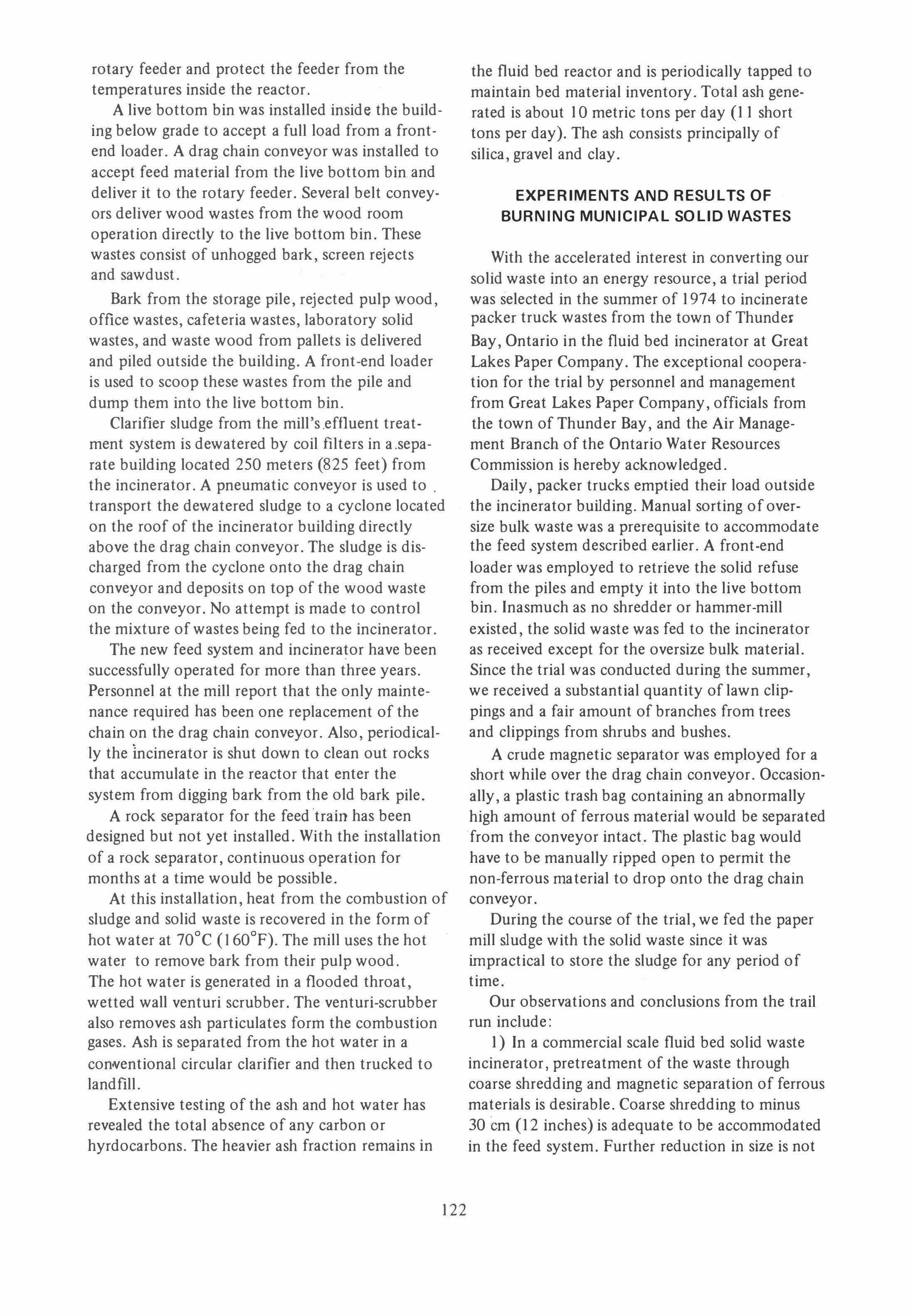
A live bottom bin was installed inside the building below grade to accept a full load from a frontend loader. A drag chain conveyor was installed to accept feed material from the live bottom bin and deliver it to the rotary feeder. Several belt conveyors deliver wood wastes from the wood room operation directly to the live bottom bin. These wastes consist of unhogged bark, screen rejects and sawdust.
Bark from the storage pile, rejected pulp wood, office wastes, cafeteria wastes, laboratory solid wastes, and waste wood from pallets is delivered and piled outside the building. A front-end loader is used to scoop these wastes from the pile and dump them into the live bottom bin.
Clarifier sludge from the mill's .effluent treatment system is dewatered by coil ftlters in a .separate building located 250 meters (825 feet) from the incinerator. A pneumatic conveyor is used to . transport the dewatered sludge to a cyclone located on the roof of the incinerator building directly above the drag chain conveyor. The sludge is discharged from the cyclone onto the drag chain conveyor and deposits on top of the wood waste on the conveyor. No attempt is made to control the mixture of wastes being fed to the incinerator.
The new feed system and incinerator have been successfully operated for more than three years. Personnel at the mill report that the only maintenance required has been one replacement of the chain on the drag chain conveyor. Also, periodically the Incinerator is shut down to clean out rocks that accumulate in the reactor that enter the system from digging bark from the old bark pile.
A rock separator for the feed 'train has been designed but not yet installed. With the installation of a rock separator, continuous operation for months at a time would be possible.
At this installation, heat from the combustion of sludge and solid waste is recovered in the form of hot water at 70°C (160°F). The mill uses the hot water to remove bark from their pulp wood. The hot water is generated in a flooded throat, wetted wall venturi scrubber. The venturi-scrubber also removes ash particulates form the combustion gases. Ash is separated from the hot water in a conventional circular clarifier and then trucked to landftll.
Extensive testing of the ash and hot water has revealed the total absence of any carbon or hyrdocarbons. The heavier ash fraction remains in
122
the fluid bed reactor and is periodically tapped to maintain bed material inventory. Total ash generated is about 10 metric tons per day (11 short tons per day). The ash consists principally of silica, gravel and clay.
EXPERIMENTS AND RESULTS OF BURNING MUNICIPAL SOLID WASTES
With the accelerated interest in converting our solid waste into an energy resource, a trial period was selected in the summer of 1974 to incinerate packer truck wastes from the town of Thunde.
Bay, Ontario in the fluid bed incinerator at Great Lakes Paper Company. The exceptional cooperation for the trial by personnel and management from Great Lakes Paper Company, officials from the town of Thunder Bay, and the Air Management Branch of the Ontario Water Resources Commission is hereby acknowledged.
Daily, packer trucks emptied their load outside the incinerator building. Manual sorting of oversize bulk waste was a prerequisite to accommodate the feed system described earlier. A front-end loader was employed to retrieve the solid refuse from the piles and empty it into the live bottom bin. Inasmuch as no shredder or hammer-mill existed, the solid waste was fed to the incinerator as received except for the oversize bulk material. Since the trial was conducted during the summer, we received a substantial quantity of lawn clippings and a fair amount of branches from trees and clippings from shrubs and bushes.
A crude magnetic separator was employed for a short while over the drag chain conveyor. Occasionally, a plastic trash bag containing an abnormally high amount of ferrous material would be separated from the conveyor intact. The plastic bag would have to be manually ripped open to permit the non-ferrous rna terial to drop onto the drag chain conveyor.
During the course of the trial, we fed the paper mill sludge with the solid waste since it was impractical to store the sludge for any period of time.
Our observations and conclusions from the trail run include:
1) In a commercial scale fluid bed solid waste incinerator, pretreatment of the waste through coarse shredding and magnetic separation of ferrous materials is desirable. Coarse shredding to minus 30 em (12 inches) is adequate to be accommodated in the feed system. Further reduction in size is not
•
•
,
•
•
. ,
•
':..-. "."",�
,
•
•
! 1
t
•
•
•
•
t •
, I ' �,
I • , , t I 1
i*
t
• N
-
•
123
required and will minimize capital cost and power required for the size reduction equipment. At the conclusion of the trial, the incinerator was shut down and cleaned out to determine what materials fed during the trial remained in the unit. There were some small ferrous iron materials, such as reinforcing rims for cans, a part of a clock works, part of a telephone dial, etc. No detrimental effect on the operation of the fluid bed was observed because of the presence of these ferrous iron materials, but it is conceivable over an extended run, the accumulation of such material could lead possibly to operating difficulty. Further examination of the material cleaned out of the reactor revealed a few very small pieces of polished glass, no aluminum, and no material which was only partially oxidized.
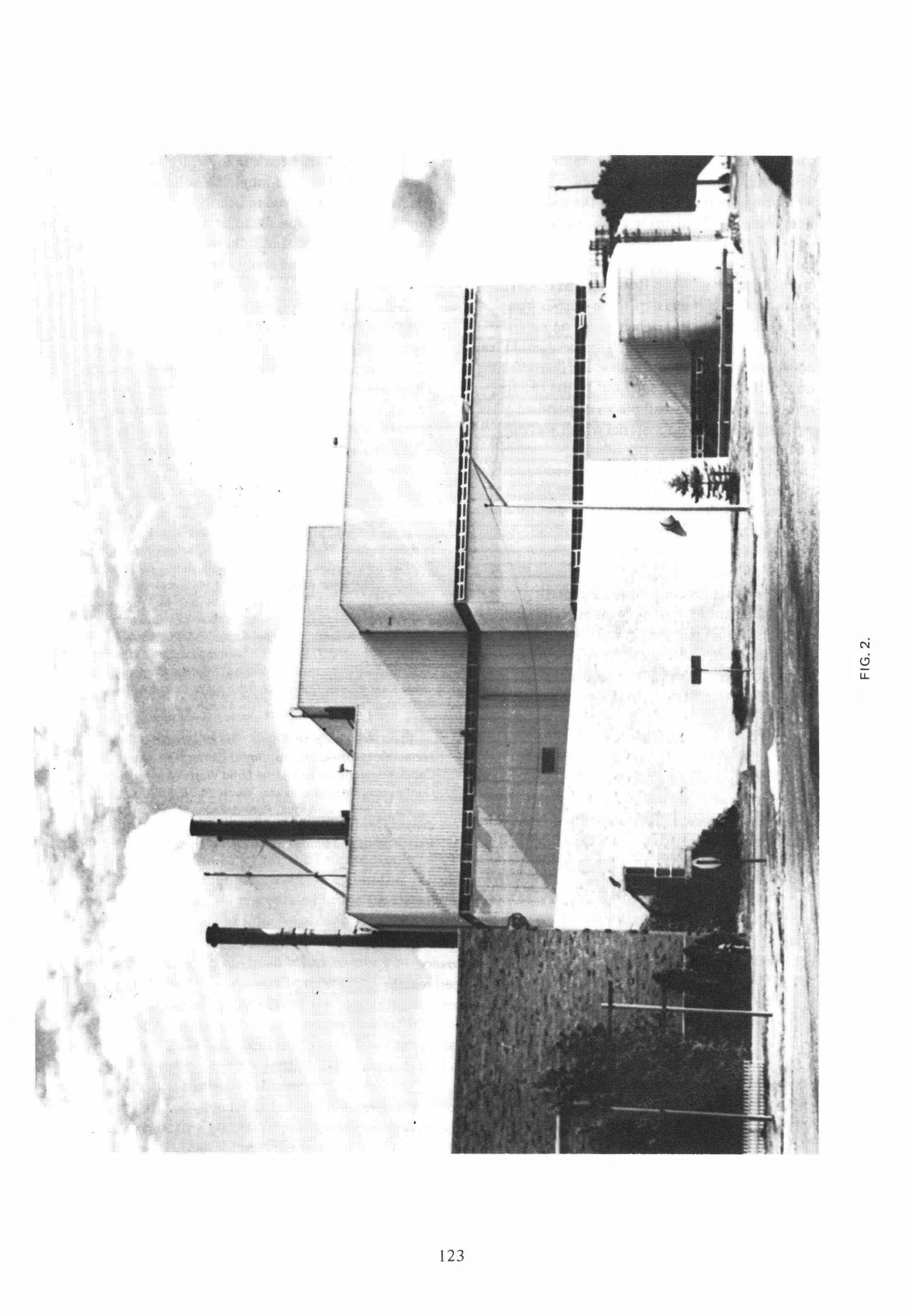
2) In order to provide a simple feed system, a balanced draft design should be adopted. An induced draft fan would maintain a slightly negative pressure in the freeboard zone of the reactor through which the solid waste would be introduced to the fluid bed incinerator. The balanced draft system would also contribute to operating a cleaner plant. Balanced draft systems are not a new concept to fluid bed incinerators, since such a design has been operating for.a couple of years at Great Northern - Nekoosa's pulp and paper mill in Port Edwards, Wisconsin (Figure 2).
SUMMARY
The application of fluidized bed technology to incineration of waste has advanced rapidly over the past two decades. Several hundred installations worldwide substantiate the fact that fluid bed
incineration can be successfully employed to incinerate liquid, sludge and solid wastes. In Europe, fluidized beds have been employed for several years in combustion of municipal solid waste and generating steam for use in heating buildings. Since fluid bed systems have demonstrated capability to burn liquids, sludges and solid wastes, combinations of these wastes can be readily accommodated in a single system.
Technological advances are continuing in designs to improve overall energy recovery, reduce capital costs and design units to accommodate up to 1000 tons per day solid waste in a single reactor. These developments will be the subject of future papers and will make the fluid bed combustion process even more competitive than it is today with other types of solid waste incinerators.
REFERENCES
[11 "Environmental Impact of Fluidized Bed Com
bustion Systems," J. H. Kleinau, Environment '75
Conference, Sydney, N.S.W., Australia, July 1-5,1975.
[21 "Fluidized Bed Treatment of Mangesia-Base Waste Effluents:' J. E. Hanway, Jr., and C. M. Wheeler,
TAPPI Engineering Conference, Session 12 - Chemical
Engineering, Atlanta, Georgia, September 20, 1967.
[31 "Primary Treatment of Newsprint Mill Effluent Including Solid Waste Incineration:' PoMan Wong of
Great Lakes Paper Company, 18th Ontario Industrial
Waste Conference, Niagara Falls, Ontario, June 13-16,
1971.
[41 "The Design and Operation of Fluidized Bed Incinerators for Solids and Liquid Wastes," G. G.
Copeland, National Industrial Solid Waste Management
Conference, Houston, Texas, March 24-26, 1970.
[51 J. McK. Limerick, Pulp & Paper Magazine of Canada, January, 1972, "Copeland System For Burning
Bark, Debris and Sludge Starts Up at Great Lakes."
Key Words Autogeneous combustion
Balanced draft systems
Energy recovery
Fluidized bed reactor
Gas scrubbers
Incineration
I ndustrial wastes
Municipal solid waste
Sludges
Pollution control systems
Thermal efficiency
124

![Mixed Plastic Wastes Pyrolysis in a Fluidized Bed Reactor ... · temperature, pressure ranges, presence of catalyst and presence of hydrogen gas or hydrogen donor compound [6]-[9]](https://img.pdfslide.us/doc/110x75/5fd73a6ee0d4da4db6118332/mixed-plastic-wastes-pyrolysis-in-a-fluidized-bed-reactor-temperature-pressure.jpg)