Embed Size (px)
Citation preview


This pageintentionally left
blank

Copyright © 2008, 2000, 1994, New Age International (P) Ltd., PublishersPublished by New Age International (P) Ltd., Publishers
All rights reserved.No part of this ebook may be reproduced in any form, by photostat, microfilm,xerography, or any other means, or incorporated into any information retrievalsystem, electronic or mechanical, without the written permission of the publisher.All inquiries should be emailed to [email protected]
PUBLISHING FOR ONE WORLD
NEW AGE INTERNATIONAL (P) LIMITED, PUBLISHERS4835/24, Ansari Road, Daryaganj, New Delhi - 110002Visit us at www.newagepublishers.com
ISBN (13) : 978-81-224-2711-0
�������
Manufacturing managers and engineers are ever concerned with improvement in quality,reduction in both manufacturing cost and delivery time. The globalization of economyrequires introduction of new products with enhanced features at competitive costs.Another challenge is the reduction in product life span. This necessitates considerabletime compression in product development cycle. Yet another significant trend is masscustomization which calls for extreme flexibility in manufacturing. The massiveoutsourcing in manufacturing is another important development in recent years.
The new edition of CAD/CAM/CIM has been bought out to focus on the responseof CIM technology to address to these challenges. Manufacturing in the new millenniumis moving towards more and more sophistication in exploiting the capabilities of computerhardware and software. Robust design methodologies and integration of shape designand functional design are included in the present edition. Optimized manufacturing is apossibility now with the extensive use of FEA. Apart from design optimization, FEA isused to model and simulate complex manufacturing processes to evolve several iterations.This enables engineers to make right parts first time every time. An additional chapteron simulation softwares has been added in the present edition to introduce this powerfultool to the students.
The authors would like to acknowledge the contribution of our erstwhile colleaguesin the PSG CAD/CAM Centre as well as Krishnaveni and Sasikala in word processingthe earlier editions and Govindaswamy for helping with some chapters in the presentedition. Acknowledgements are due to K.J. Reddy for providing some models forreproduction in this edition and to Pradeep for critical suggestions. The excellent supportand encouragement extended by Padmini, Anitha and Hari during the revision of thisedition is gratefully acknowledged.
P. RadhakrishnanP. RadhakrishnanP. RadhakrishnanP. RadhakrishnanP. RadhakrishnanS. SubramanianS. SubramanianS. SubramanianS. SubramanianS. Subramanian
V. RajuV. RajuV. RajuV. RajuV. Raju

This pageintentionally left
blank
�����
PREFACE (v)
�� �� ����� ��������� ����������� �
1.1 INTRODUCTION 11.2 TYPES OF MANUFACTURING 31.3 EVOLUTION OF COMPUTER INTEGRATED MANUFACTURING 41.4 CIM HARDWARE AND CIM SOFTWARE 61.5 NATURE AND ROLE OF THE ELEMENTS OF CIM SYSTEM 71.6 DEVELOPMENT OF CIM 10
�� �������������� ��� ��������� ��
2.1 INTRODUCTION 132.2 PRODUCT DEVELOPMENT CYCLE 132.3 SEQUENTIAL ENGINEERING 162.4 CONCURRENT ENGINEERING 182.5 COMPARISON OF CONCURRENT ENGINEERING AND SEQUENTIAL ENGINEERING 192.6 IMPLEMENTATION OF CONCURRENT ENGINEERING 212.7 CONCURRENT ENGINEERING AND INFORMATION TECHNOLOGY 232.8 SOFT AND HARD PROTOTYPING 252.9 CHARACTERISTICS OF CONCURRENT ENGINEERING 252.10 KEY FACTORS INFLUENCING THE SUCCESS OF CE 262.11 EXAMPLE OF CONCURRENT ENGINEERING 262.12 TECHNIQUES TO IMPROVE MANUFACTURABILITY AND REDUCE LEAD TIME 272.13 IMPROVING THE DESIGN 322.14 TAGUCHI METHOD FOR ROBUST DESIGN 342.15 VALUE ENGINEERING 342.16 PRODUCT LIFE CYCLE MANAGEMENT 35
viii Contents
�� ������������� �� ������������ ��
3.1 INTRODUCTION 413.2 GRAPHIC PRIMITIVES 423.3 POINT PLOTTING 433.4 DRAWING OF LINES 433.5 BRESENHAM’S CIRCLE ALGORITHM 473.6 ELLIPSE 553.7 TRANSFORMATION IN GRAPHICS 553.8 CO-ORDINATE SYSTEMS USED IN GRAPHICS AND WINDOWING 553.9 VIEW PORT 563.10 2-D TRANSFORMATIONS 563.11 HOMOGENEOUS TRANSFORMATIONS 603.12 COMBINATION TRANSFORMATIONS 613.13 CLIPPING 633.14 3-DIMENSIONAL TRANSFORMATIONS 633.15 PROJECTIONS 643.16 SCAN CONVERSION 663.17 RENDERING 693.18 RASTERIZING POLYGONS 693.19 HIDDEN SURFACE REMOVAL 703.20 ANTI ALIASING 723.21 REFLECTION 733.22 SHADING 753.23 GENERATION OF CHARACTERS 76
�� �� ������������� ��
4.1 INTRODUCTION 774.2 COMPUTER FUNDAMENTALS 784.3 CLASSIFICATION OF COMPUTERS 794.4 DATA COMMUNICATIONS 834.5 DESIGN WORK STATIONS 894.6 ARCHITECTURE OF A TYPICAL GRAPHICS WORKSTATION 904.7 INTERACTIVE DISPLAY DEVICES 934.8 INPUT DEVICES 974.9 OUTPUT DEVICES 100
�� ��������� �� ����� ������� �� ���
5.1 INTRODUCTION 1035.2 OPERATING SYSTEM (OS) 1045.3 COMPARISON OF COMMANDS IN POPULAR OPERATING SYSTEMS 1065.4 UNIX - OPERATING SYSTEM 1085.5 ARCHITECTURE OF UNIX SYSTEM 109
Con
ten
tsC
onte
nts
Con
ten
tsC
onte
nts
Con
ten
ts
ixContents
5.6 GRAPHICAL USER INTERFACES (WINDOWS ENVIRONMENT) 1135.7 MS WINDOWS 1145.8 WINDOWS NT 1155.9 LINUX 120
�� ��� ����� �������� �������� ���
6.1 INTRODUCTION 1216.2 GEOMETRIC MODELING 1236.3 SALIENT FEATURES OF SOLID MODELING 1286.4 COMMAND, MENU AND ICON DRIVEN SOFTWARES 1366.5 FEATURES OF A DRAFTING PACKAGE 1386.6 DRAWING UTILITIES 1396.7 ENTITIES 1426.8 EDIT COMMANDS 1436.9 BLOCKS AND SYMBOLS 1436.10 DISPLAY 1446.11 CROSS HATCHING AND PATTERN FILLING 1446.12 DIMENSIONING 1456.13 ENQUIRY COMMANDS 1466.14 3-D DRAWINGS 1476.15 PLOTTING A DRAWING 1496.16 CONFIGURING THE DRAFTING SOFTWARE 1496.17 CUSTOMISATION 1496.18 DRAWING INTERCHANGE FILES 1506.19 DRAWING OFFICE MANAGEMENT 1506.20 SURFACE MODELING 1526.21 REPRESENTATION OF CURVES AND SURFACES 1546.22 DESIGN OF CURVED SHAPES 1556.23 CUBIC SPLINES 1566.24 BEZIER CURVES 1596.25 B-SPLINES 1616.26 NURBS AND B-SPLINES 1626.27 REPRESENTATION OF SURFACES 1636.28 DESIGN OF SURFACES 1636.29 PARAMETRIC DESIGN OF SURFACES 1636.30 BICUBIC POLYNOMIAL SURFACE PATCHES 1646.31 BEZIER BICUBIC SURFACE PATCHES 1656.32 CUBIC B-SPLINE SURFACES 1666.33 SURFACE MODELING IN COMMERCIAL DRAFTING AND MODELING SOFTWARE 1666.34 THE CONCEPTUAL DESIGN PROCESS 1746.35 SKETCHING THE GEOMETRY 1766.36 UNDERSTANDING CURVE AND SURFACE DESIGN 1776.37 OTHER FEATURES USEFUL FOR CONCEPTUAL DESIGN 1856.38 DATA TRANSFER TO OTHER SOFTWARES 185
x Contents
�� ��������� ��� ������������������� ����� � !
7.1 INTRODUCTION 1897.2 GENERAL STEPS INVOLVED IN FINITE ELEMENT ANALYSIS 1917.3 TYPES OF ANALYSIS 1937.4 DEGREES OF FREEDOM 1957.5 INFLUENCE COEFFICIENTS 1967.6 ELEMENT AND STRUCTURE STIFFNESS EQUATIONS 1967.7 ASSEMBLY OF ELEMENTS 2127.8 FINITE ELEMENT ANALYSIS PACKAGES 2157.9 GENERAL STRUCTURE OF A FINITE ELEMENT ANALYSIS PROCEDURE 2167.10 ARCHITECTURE OF FINITE ELEMENT SOFTWARE 2217.11 USING A FINITE ELEMENT ANALYSIS PACKAGE FOR SIMPLE PROBLEMS 2227.12 ELEMENTS IN A FINITE ELEMENT ANALYSIS SOFTWARE 2237.13 EXAMPLES OF SOLUTION USING A SOFTWARE 2287.14 MANUFACTURING APPLICATIONS 2427.15 WELDING SIMULATION 2437.16 FINITE ELEMENT ANALYSIS APPLICATIONS TO METAL FORMING 2447.17 SIMULATION OF HEAT TRATMENT 2457.18 PLASTIC INJECTION MOLDING 245
� �� �����"�����������"��� ����� ����� ���
8.1 INTRODUCTION 2478.2 DATABASE REQUIREMENTS OF CIM 2498.3 DATA BASE 2498.4 DATABASE MANAGEMENT 2518.5 FEATURES OF A DATABASE MANAGEMENT SYSTEM 2518.6 DATABASE MODELS 2528.7 DBMS ARCHITECTURE 2558.8 QUERY LANGUAGE 2558.9 STRUCTURED QUERY LANGUAGE [SQL] 2568.10 SQL AS A KNOWLEDGE BASE QUERY LANGUAGE 2578.11 PRODUCT DATA MANAGEMENT (PDM) 2588.12 ADVANTAGES OF PDM 260
!� �� ����������������� �������� ���
9.1 INTRODUCTION 2639.2 PROCESS PLANNING 2639.3 STRUCTURE OF A PROCESS PLANNING SOFTWARE 2669.4 INFORMATION REQUIRED FOR PROCESS PLANNING 2669.5 OPERATION OF A TYPICAL COMPUTER AIDED PROCESS PLANNING SOFTWARE 2679.6 CAD BASED PROCESS PLANNING - CERTAIN LIMITATIONS AND PROBLEMS 2709.7 GROUP TECHNOLOGY 272
Con
ten
tsC
onte
nts
Con
ten
tsC
onte
nts
Con
ten
ts
xiContents
9.8 CODING STRUCTURES 2749.9 OPITZ CLASSIFICATION SYSTEM 2759.10 THE MICLASS SYSTEM 2779.11 THE CODE SYSTEM 2779.12 BENEFITS OF GROUP TECHNOLOGY 2779.13 PROCESS SELECTION 2799.14 EXPERIENCE-BASED PLANNING 2799.15 HAND BOOKS/DATA BOOKS/MANUALS 2809.16 DECISION TABLES AND DECISION TREES 2809.17 PROCESS CAPABILITY 2809.18 METHODS OF COMPUTER AIDED PROCESS PLANNING 2829.19 VARIANT PROCESS PLANNING 2829.20 GENERATIVE PROCESS PLANNING 2849.21 IMPLEMENTATION CONSIDERATIONS 2889.22 PROCESS PLANNING SYSTEMS 289
��� ������������ �������� ���� ������������ ������
����� ����� �� �!�
10.1 INTRODUCTION 29310.2 BACKGROUND 29410.3 ROLE OF MRP-II IN A CIM SYSTEM 29510.4 MAJOR MODULES OF A MANUFACTURING RESOURCES PLANNING (MRP) SOFTWARE 29610.5 MANUFACTURING APPLICATIONS 29610.6 ENGINEERING APPLICATIONS 30410.7 FINANCIAL APPLICATIONS 30710.8 MARKETING APPLICATIONS 31110.9 MISCELLANEOUS APPLICATIONS 31310.10 COMMON ACRONYMS USED IN AN MRP-II ENVIRONMENT 31410.11 STATUS OF MRP-II SOFTWARE 31410.12 DYNAMIC ENTERPRISES 31510.13 ENTERPRISE RESOURCE PLANNING (ERP) 31610.14 SUPPLY CHAIN MANAGEMENT 32010.15 VIRTUAL MANUFACTURING 32210.16 SELECTION OF AN ERP PACKAGE 32210.17 ERP IN INDIA 32310.18 DYNAMIC ENTERPRISE MODELLING (DEM) 323
��� ��������������� ���� ���
11.1 INTRODUCTION 32711.2 TYPES OF AUTOMATION SYSTEMS 32811.3 PROGRAMMABLE LOGIC CONTROLLERS 32911.4 PARTS OF A TYPICAL PLC SYSTEM 33211.5 OPERATION OF A PLC 333
xii Contents
11.6 PROGRAMMING OF PLC 33311.7 EXAMPLE OF APPLICATION OF PLC IN A CNC MACHINE 33511.8 FACTORY LEVEL CONTROL 338
��� ���� ������� ��� ���
12.1 INTRODUCTION 34112.2 PRINCIPLE OF OPERATION OF A NUMERICAL CONTROLLED MACHINE 34212.3 HISTORICAL DEVELOPMENT 35112.4 TYPES OF CNC MACHINES 35312.5 FEATURES OF CNC SYSTEMS 37312.6 DIRECT NUMERICAL CONTROL (DNC) 37912.7 FUNCTIONS AVAILABLE IN A TYPICAL CNC SYSTEM 38412.8 STANDARD CONTROLLERS 38612.9 SOME OF THE FEATURES AVAILABLE IN TYPICAL HIGH END CNC SYSTEM 38712.10 GENERAL PROGRAMMING FEATURES OF CNC SYSTEMS 38912.11 PROGRAMMING OF CNC MACHINE TOOLS 40312.12 HINTS FOR PROGRAMMING 41412.13 EXAMPLE OF PROGRAMMING A VERTICAL MACHINING CENTRE 42312.14 CNC TURNING A GEAR BLANK 43112.15 CNC TURNING A CASTING 44212.16 CNC PROGRAM DEVELOPMENT AND VIRTUAL MACHINING USING CAM
TECHNOLOGY 45112.17 TECHNOLOGY OF CAM 45412.18 PROCEDURE OF CAM 45512.19 MANUFACTURING OPERATIONS 45912.20 TOOL MOTION PARAMETERS 46212.21 AUXILIARY NC SEQUENCES 46312.22 CL DATA FILES 46312.23 NC POST-PROCESSING 46412.24 VIRTUAL MACHINING 46412.25 SUMMARY 465
��� ��"�� ��� �� ����� ��������� ����������� ���
13.1 INTRODUCTION 47113.2 DEFINITION OF A ROBOT 47213.3 TYPES OF ROBOTS 47413.4 PERFORMANCE CAPABILITIES 48113.5 PROGRAMMING ROBOTS 48413.6 GEOMETRIC REQUIREMENTS FOR THE CAD/ROBOT LINKAGE 49313.7 SIMULATION 49413.8 ADAPTIVE CONTROL 49413.9 ROBOT OPERATION 495
Con
ten
tsC
onte
nts
Con
ten
tsC
onte
nts
Con
ten
ts
xiiiContents
13.10 ENDS-OF-ARM-TOOLING 49613.11 CONTROL SYSTEM OPERATION 49613.12 APPLICATIONS OF INDUSTRIAL ROBOTS 49613.13 THE INTEGRATION OF THE INDUSTRIAL ROBOT INTO A CIM SYSTEM 50013.14 PRESENTATION OF WORK TO ROBOTS 50113.15 PRODUCT DESIGN FOR AUTOMATIC MANUFACTURE BY ROBOTS 50113.16 MANUFACTURERS OF ROBOTS 502
��� �� ������������������ ������ ���
14.1 INTRODUCTION 50514.2 TOTAL QUALITY MANAGEMENT (TQM) 50614.3 QC AND CIM 50714.4 INSPECTION AND TESTING 50814.5 STATISTICAL PROCESS CONTROL (SPC) 50914.6 OBJECTIVES OF CAQC 50914.7 ROLE OF COMPUTER IN QC 50914.8 COORDINATE MEASURING MACHINE 51014.9 NON-CONTACT INSPECTION METHODS 51214.10 POST PROCESS METROLOGY 51614.11 COMPUTER AIDED INSPECTION USING ROBOTS 51714.12 INTEGRATED COMPUTER AIDED INSPECTION SYSTEMS 51814.13 FLEXIBLE INSPECTION SYSTEM (FIS) 520
��� ����� �������������#��� ���
15.1 INTRODUCTION 52315.2 PRINCIPLES OF NETWORKING 52315.3 NETWORK TECHNIQUES 52615.4 LOCAL AREA NETWORK (LAN) 52615.5 COMPONENTS OF A SMALL LOCAL AREA NETWORK 52815.6 NETWORK WIRING METHODS 52915.7 NETWORK INTERFACE CARDS 53215.8 NETWORKING STANDARDS AND THEIR DEVELOPMENT 53315.9 EXAMPLES OF NETWORK STANDARDS 53615.10 ETHERNET 53715.11 ISSUES IN INTER-SYSTEM COMMUNICATION 53815.12 NETWORK OPERATING SYSTEMS 54015.13 SYSTEM SECURITY 54115.14 MANAGING REMOTE SYSTEMS IN A NETWORK 54115.15 DESIGN ACTIVITY IN A NETWORKED ENVIRONMENT 54215.16 ENGINEERING CHANGE CONTROL 54215.17 NETWORKING IN A MANUFACTURING COMPANY 54215.18 NETWORK FILE SYSTEM (NFS) 543
xiv Contents
15.19 INTERNET 54815.20 HARDWARE ELEMENTS OF A NETWORK 55115.21 ATM (ASYNCHRONOUS TRANSFER MODE) NETWORKS 55415.22 ENTERPRISE WIDE NETWORK 55515.23 DOCUMENT AND WORKFLOW MANAGEMENT SYSTEM 55715.24 A CASE STUDY OF APPLICATION OF GLOBAL NETWORKING 562
��� �����"������� ����������� ���
16.1 INTRODUCTION 56516.2 FASTER DESIGN THRUOGHPUT 56616.3 WEB BASED DESIGN 56716.4 CHANGING DESIGN APPROACHES 56816.5 EXTENDED ENTERPRISES 57116.6 SOFTWARE FOR COLLABORATIVE DESIGN AND ENTERPRISE-WIDE PRODUCT
VISUALIZATION 572
��� �������� ������ ���
17.1 INTRODUCTION 57517.2 STANDARDS FOR GRAPHICS PROGRAMMING 57617.3 FEATURES OF GKS 57617.4 OTHER GRAPHICS STANDARDS 57817.5 PHIGS 57817.6 OPENGL 58017.7 PARASOLID 58117.8 ACIS 58317.9 EXCHANGE OF CAD DATA BETWEEN SOFTWARE PACKAGES 58417.10 DXF FILES 58517.11 INITIAL GRAPHICS EXCHANGE SPECIFICATION (IGES) GRAPHICS STANDARD 58717.12 PRODUCT DATA EXCHANGE SPECIFICATION (PDES) 59017.13 OTHER DATA EXCHANGE FORMATS 59017.1.4 PRODUCT DATA TECHNOLOGY SUPPORT FOR COMPUTER AIDED CONCURRENT
ENGINEERING 590
� � �� � ���� �!�
18.1 INTRODUCTION 59718.2 ESPRIT - CIM OSA MODEL 59918.3 THE NIST - AMRF HIERARCHICAL MODEL 60118.4 THE SIEMENS MODEL OF CIM 60218.5 THE CIM MODEL OF DIGITAL EQUIPMENT CORPORATION 60318.6 THE IBM CONCEPT OF CIM 60418.7 PRESENT SCENARIO 607
Con
ten
tsC
onte
nts
Con
ten
tsC
onte
nts
Con
ten
ts
xvContents
�!� ���$�"��� ������������ �� ��!
19.1 INTRODUCTION 60919.2 SUBSYSTEMS OF FMS 61019.3 SCOPE OF FMS 61119.4 FMS COMPARED TO OTHER TYPES OF MANUFACTURING APPROACHES 61119.5 TYPES OF FMS 61219.6 BENEFITS OF FMS 62019.7 MAJOR ELEMENTS OF FMS 62219.8 OPTIMISATION OF FMS 62719.9 OPERATIONAL ELEMENTS OF A TYPICAL FLEXIBLE MANUFACTURING CELL 62819.10 TYPICAL FMS LAYOUT 63819.11 FMS DEVELOPMENT IN INDIA 639
��� ���� ���������������������� ���
20.1 INTRODUCTION 64120.2 SHOP FLOOR CONTROL 64320.3 SHOP FLOOR DATA COLLECTION 64620.4 TYPES OF DATA COLLECTION SYSTEMS 64620.5 DATA INPUT TECHNIQUES 64720.6 AUTOMATIC DATA COLLECTION SYSTEM 64820.7 BAR CODE TECHNOLOGY 64820.8 OPTICAL CHARACTER RECOGNITION 65020.9 MAGNETIC INK CHARACTER RECOGNITION 65120.10 VOICE RECOGNITION 65120.11 SMART CARDS 65120.12 DATA ACQUISITION SYSTEMS (DAS) 652
��� � ������� ��� ����������� ���
21.1 INTRODUCTION 65321.2 TYPES OF SIMULATION 65421.3 TECHNIQUES OF SIMULATION 65521.4 SIMULATION PROCESS FOR MANUFACTURING SYSTEMS ANALYSIS 65621.5 SIMULATION SOFTWARE PACKAGES 65621.6 APPLICATION OF SIMULATION 65721.7 PROCEDURE FOR SIMULATION USING SOFTWARE 659
����$ ���

This pageintentionally left
blank
�������������� ���
� ��� ������
�� ����
1.1 INTRODUCTION
Computer Integrated Manufacturing (CIM) encompasses the entire range of productdevelopment and manufacturing activities with all the functions being carried out withthe help of dedicated software packages. The data required for various functions are passedfrom one application software to another in a seamless manner. For example, the productdata is created during design. This data has to be transferred from the modeling softwareto manufacturing software without any loss of data. CIM uses a common databasewherever feasible and communication technologies to integrate design, manufacturingand associated business functions that combine the automated segments of a factory ora manufacturing facility. CIM reduces the human component of manufacturing andthereby relieves the process of its slow, expensive and error-prone component. CIM standsfor a holistic and methodological approach to the activities of the manufacturing enterprisein order to achieve vast improvement in its performance.
This methodological approach is applied to all activities from the design of the productto customer support in an integrated way, using various methods, means and techniquesin order to achieve production improvement, cost reduction, fulfillment of scheduleddelivery dates, quality improvement and total flexibility in the manufacturing system.CIM requires all those associated with a company to involve totally in the process of productdevelopment and manufacture. In such a holistic approach, economic, social and humanaspects have the same importance as technical aspects.
CIM also encompasses the whole lot of enabling technologies including total qualitymanagement, business process reengineering, concurrent engineering, workflowautomation, enterprise resource planning and flexible manufacturing.
A distinct feature of manufacturing today is mass customization. This implies thatthough the products are manufactured in large quantities, products must incorporate
An overview of CIM is presented in this chapter. A brief account of the evolution of CIM isincluded. The major functions carried out in a manufacturing plant are surveyed and thedifferent levels of integration are identified.
2 CAD/CAM/CIM
customer-specific changes to satisfy the diverse requirements of the customers. Thisrequires extremely high flexibility in the manufacturing system.
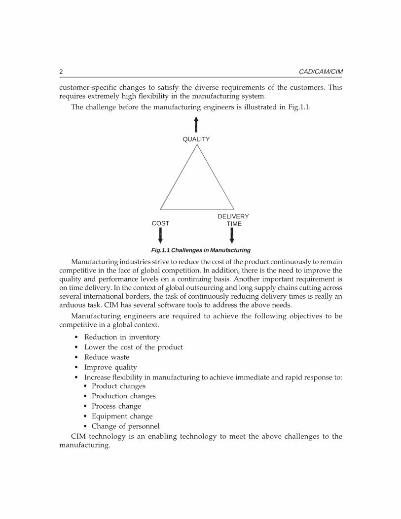
The challenge before the manufacturing engineers is illustrated in Fig.1.1.
COSTDELIVERY
TIME
QUALITY
Fig.1.1 Challenges in Manufacturing
Manufacturing industries strive to reduce the cost of the product continuously to remaincompetitive in the face of global competition. In addition, there is the need to improve thequality and performance levels on a continuing basis. Another important requirement ison time delivery. In the context of global outsourcing and long supply chains cutting acrossseveral international borders, the task of continuously reducing delivery times is really anarduous task. CIM has several software tools to address the above needs.
Manufacturing engineers are required to achieve the following objectives to becompetitive in a global context.
• Reduction in inventory• Lower the cost of the product• Reduce waste• Improve quality• Increase flexibility in manufacturing to achieve immediate and rapid response to:
• Product changes• Production changes• Process change• Equipment change• Change of personnel
CIM technology is an enabling technology to meet the above challenges to themanufacturing.
Ch
ap
ter
1C
ha
pte
r 1
Ch
ap
ter
1C
ha
pte
r 1
Ch
ap
ter
1
3Computer Integrated Manufacturing
The advances in automation have enabled industries to develop islands of automation.Examples are flexible manufacturing cells, robotized work cells, flexible inspection cellsetc. One of the objectives of CIM is to achieve the consolidation and integration of theseislands of automation. This requires sharing of information among different applicationsor sections of a factory, accessing incompatible and heterogeneous data and devices. Theultimate objective is to meet the competition by improved customer satisfaction throughreduction in cost, improvement in quality and reduction in product development time.
CIM makes full use of the capabilities of the digital computer to improvemanufacturing. Two of them are:
i. Variable and Programmable automationii. Real time optimizationThe computer has the capability to accomplish the above for hardware components of
manufacturing (the manufacturing machinery and equipment) and software componentof manufacturing (the application software, the information flow, database and so on).
The capabilities of the computer are thus exploited not only for the various bits andpieces of manufacturing activity but also for the entire system of manufacturing. Computershave the tremendous potential needed to integrate the entire manufacturing system andthereby evolve the computer integrated manufacturing system.
1.2 TYPES OF MANUFACTURING
The term “manufacturing” covers a broad spectrum of activities. Metal working industries,process industries like chemical plants, oil refineries, food processing industries, electronicindustries making microelectronic components, printed circuit boards, computers andentertainment electronic products etc. are examples of manufacturing industries.Manufacturing involves fabrication, assembly and testing in a majority of situations. However,in process industries operations are of a different nature.
Manufacturing industries can be grouped into four categories:
i.i.i.i.i. Continuous Process IndustriesContinuous Process IndustriesContinuous Process IndustriesContinuous Process IndustriesContinuous Process IndustriesIn this type of industry, the production process generally follows a specificsequence. These industries can be easily automated and computers are widelyused for process monitoring, control and optimization. Oil refineries, chemicalplants, food processing industries, etc are examples of continuous processindustries.
ii.ii.ii.ii.ii. Mass Production IndustriesMass Production IndustriesMass Production IndustriesMass Production IndustriesMass Production IndustriesIndustries manufacturing fasteners (nuts, bolts etc.), integrated chips, automobiles,entertainment electronic products, bicycles, bearings etc. which are all massproduced can be classified as mass production industries. Production lines arespecially designed and optimized to ensure automatic and cost effective operation.Automation can be either fixed type or flexible.
4 CAD/CAM/CIM
iii.iii.iii.iii.iii. Batch Production (Discrete Manufacturing)Batch Production (Discrete Manufacturing)Batch Production (Discrete Manufacturing)Batch Production (Discrete Manufacturing)Batch Production (Discrete Manufacturing)The largest percentage of manufacturing industries can be classified as batchproduction industries. The distinguishing features of this type of manufacture arethe small to medium size of the batch, and varieties of such products to be takenup in a single shop. Due to the variety of components handled, work centresshould have broader specifications. Another important fact is that small batchsize involves loss of production time associated with product changeover.
As mentioned earlier, integration of computer in process industries for productionautomation, process monitoring and control and optimization is relatively easy. In thecase of mass production and batch production computer integration faces a number ofproblems as there are a large number of support activities which are to be tied together.These are discussed in detail later in this chapter.
Automation of manufacture has been implemented using different techniques sincethe turn of the 20th Century. Fixed automation is the first type to emerge. Single spindleautomatic lathe, multi spindle automatic lathe and transfer lines are examples of fixedautomation. Fixed automation using mechanical, electrical, pneumatic and hydraulicsystems is widely used in automobile manufacturing. This type of automation has a severelimitation - these are designed for a particular product and any product change will requireextensive modifications to the automation system.
The concept of programmable automation was introduced later. These were electricallycontrolled systems and programs were stored in punched cards and punched tapes. Typicalexamples of programmable automation are:
i. Electrical programme controlled milling machinesii. Hydraulically operated Automatic lathes with programmable control drum
iii. Sequencing machines with punched card control /plug board control
Development of digital computers, microelectronics and microprocessors significantlyaltered the automation scenario during 1950-1990. Machine control systems are nowdesigned around microprocessors and microelectronics is part and parcel of industrialdrives and control. The significant advances in miniaturization through integration of largenumber of components into small integrated chips and the consequent improvement inreliability and performance have increased the popularity of microelectronics. This hasresulted in the availability of high performance desktop computing machines as well asfile servers which can be used for industrial control with the help of application softwarepackages.
1.3 EVOLUTION OF COMPUTER INTEGRATED MANUFACTURING
Computer Integrated Manufacturing (CIM) is considered a natural evolution of thetechnology of CAD/CAM which by itself evolved by the integration of CAD and CAM.Massachusetts Institute of Technology (MIT, USA) is credited with pioneering the
Ch
ap
ter
1C
ha
pte
r 1
Ch
ap
ter
1C
ha
pte
r 1
Ch
ap
ter
1
5Computer Integrated Manufacturing
development in both CAD and CAM. The need to meet the design and manufacturingrequirements of aerospace industries after the Second World War necessitated thedevelopment these technologies. The manufacturing technology available during late 40’sand early 50’s could not meet the design and manufacturing challenges arising out of theneed to develop sophisticated aircraft and satellite launch vehicles. This prompted the USAir Force to approach MIT to develop suitable control systems, drives and programmingtechniques for machine tools using electronic control.
The first major innovation in machine control is the Numerical Control (NC),demonstrated at MIT in 1952. Early Numerical Control Systems were all basically hardwiredsystems, since these were built with discrete systems or with later first generation integratedchips. Early NC machines used paper tape as an input medium. Every NC machine wasfitted with a tape reader to read paper tape and transfer the program to the memory of themachine tool block by block. Mainframe computers were used to control a group of NCmachines by mid 60’s. This arrangement was then called Direct Numerical Control (DNC)as the computer bypassed the tape reader to transfer the program data to the machinecontroller. By late 60’s mini computers were being commonly used to control NC machines.At this stage NC became truly soft wired with the facilities of mass program storage, off-line editing and software logic control and processing. This development is called ComputerNumerical Control (CNC).
Since 70’s, numerical controllers are being designed around microprocessors, resultingin compact CNC systems. A further development to this technology is the distributednumerical control (also called DNC) in which processing of NC program is carried out indifferent computers operating at different hierarchical levels - typically from mainframehost computers to plant computers to the machine controller. Today the CNC systems arebuilt around powerful 32 bit and 64 bit microprocessors. PC based systems are alsobecoming increasingly popular.
Manufacturing engineers also started using computers for such tasks like inventorycontrol, demand forecasting, production planning and control etc. CNC technology wasadapted in the development of co-ordinate measuring machine’s (CMMs) which automatedinspection. Robots were introduced to automate several tasks like machine loading,materials handling, welding, painting and assembly. All these developments led to theevolution of flexible manufacturing cells and flexible manufacturing systems in late 70’s.
Evolution of Computer Aided Design (CAD), on the other hand was to cater to thegeometric modeling needs of automobile and aeronautical industries. The developmentsin computers, design workstations, graphic cards, display devices and graphic inputand output devices during the last ten years have been phenomenal. This coupled withthe development of operating system with graphic user interfaces and powerful interactive(user friendly) software packages for modeling, drafting, analysis and optimizationprovides the necessary tools to automate the design process.
CAD in fact owes its development to the APT language project at MIT in early 50’s.Several clones of APT were introduced in 80’s to automatically develop NC codes from
6 CAD/CAM/CIM
the geometric model of the component. Now, one can model, draft, analyze, simulate,modify, optimize and create the NC code to manufacture a component and simulate themachining operation sitting at a computer workstation.
If we review the manufacturing scenario during 80’s we will find that themanufacturing is characterized by a few islands of automation. In the case of design,the task is well automated. In the case of manufacture, CNC machines, DNC systems,FMC, FMS etc provide tightly controlled automation systems. Similarly computer controlhas been implemented in several areas like manufacturing resource planning, accounting,sales, marketing and purchase. Yet the full potential of computerization could not beobtained unless all the segments of manufacturing are integrated, permitting the transferof data across various functional modules. This realization led to the concept of computerintegrated manufacturing. Thus the implementation of CIM required the developmentof whole lot of computer technologies related to hardware and software.
1.4 CIM HARDWARE AND CIM SOFTWARE
CIM Hardware comprises the following:
i. Manufacturing equipment such as CNC machines or computerized work centres,robotic work cells, DNC/FMS systems, work handling and tool handling devices,storage devices, sensors, shop floor data collection devices, inspection machinesetc.
ii. Computers, controllers, CAD/CAM systems, workstations / terminals, data entryterminals, bar code readers, RFID tags, printers, plotters and other peripheraldevices, modems, cables, connectors etc.,
CIM software comprises computer programmes to carry out the following functions:
Management Information SystemSalesMarketingFinanceDatabase ManagementModeling and DesignAnalysisSimulationCommunicationsMonitoringProduction ControlManufacturing Area ControlJob Tracking
Ch
ap
ter
1C
ha
pte
r 1
Ch
ap
ter
1C
ha
pte
r 1
Ch
ap
ter
1
7Computer Integrated Manufacturing
Inventory ControlShop Floor Data CollectionOrder EntryMaterials HandlingDevice DriversProcess PlanningManufacturing Facilities PlanningWork Flow AutomationBusiness Process EngineeringNetwork ManagementQuality Management
1.5 NATURE AND ROLE OF THE ELEMENTS OF CIM SYSTEM
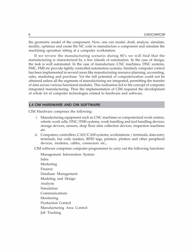
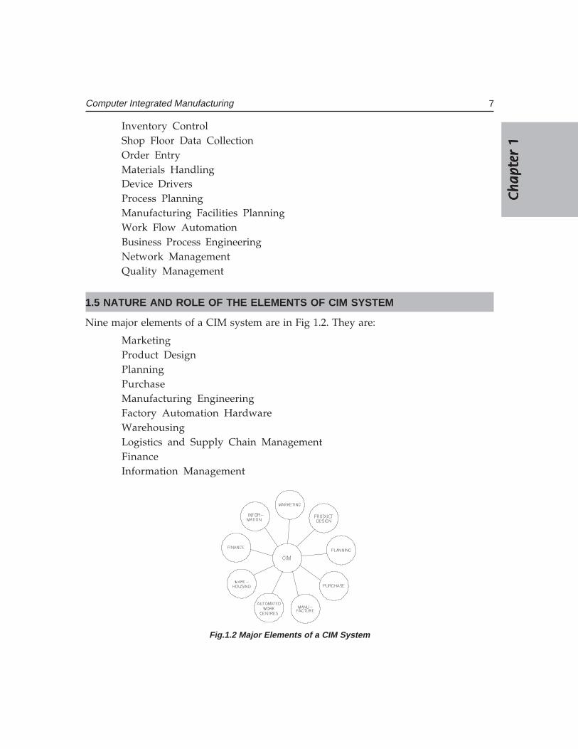
Nine major elements of a CIM system are in Fig 1.2. They are:
MarketingProduct DesignPlanningPurchaseManufacturing EngineeringFactory Automation HardwareWarehousingLogistics and Supply Chain ManagementFinanceInformation Management
Fig.1.2 Major Elements of a CIM System
8 CAD/CAM/CIM
i. Marketing: Marketing: Marketing: Marketing: Marketing: The need for a product is identified by the marketing division. Thespecifications of the product, the projection of manufacturing quantities and thestrategy for marketing the product are also decided by the marketing department.Marketing also works out the manufacturing costs to assess the economic viabilityof the product.
ii. Product Design: Product Design: Product Design: Product Design: Product Design: The design department of the company establishes the initialdatabase for production of a proposed product. In a CIM system this isaccomplished through activities such as geometric modeling and computer aideddesign while considering the product requirements and concepts generated bythe creativity of the design engineer. Configuration management is an importantactivity in many designs. Complex designs are usually carried out by severalteams working simultaneously, located often in different parts of the world. Thedesign process is constrained by the costs that will be incurred in actual productionand by the capabilities of the available production equipment and processes. Thedesign process creates the database required to manufacture the part.
iii. Planning:Planning:Planning:Planning:Planning: The planning department takes the database established by thedesign department and enriches it with production data and information toproduce a plan for the production of the product. Planning involves severalsubsystems dealing with materials, facility, process, tools, manpower, capacity,scheduling, outsourcing, assembly, inspection, logistics etc. In a CIM system,this planning process should be constrained by the production costs and bythe production equipment and process capability, in order to generate anoptimized plan.
iv. Purchase:Purchase:Purchase:Purchase:Purchase: The purchase departments is responsible for placing the purchaseorders and follow up, ensure quality in the production process of the vendor,receive the items, arrange for inspection and supply the items to the stores orarrange timely delivery depending on the production schedule for eventual supplyto manufacture and assembly.
v. Manufacturing Engineering: Manufacturing Engineering: Manufacturing Engineering: Manufacturing Engineering: Manufacturing Engineering: Manufacturing Engineering is the activity of carryingout the production of the product, involving further enrichment of the databasewith performance data and information about the production equipment andprocesses. In CIM, this requires activities like CNC programming, simulation andcomputer aided scheduling of the production activity. This should include on-line dynamic scheduling and control based on the real time performance of theequipment and processes to assure continuous production activity. Often, theneed to meet fluctuating market demand requires the manufacturing systemflexible and agile.
vi. Factory Automation Hardware:Factory Automation Hardware:Factory Automation Hardware:Factory Automation Hardware:Factory Automation Hardware: Factory automation equipment further enrichesthe database with equipment and process data, resident either in the operator orthe equipment to carry out the production process. In CIM system this consistsof computer controlled process machinery such as CNC machine tools, flexible
Ch
ap
ter
1C
ha
pte
r 1
Ch
ap
ter
1C
ha
pte
r 1
Ch
ap
ter
1
9Computer Integrated Manufacturing
manufacturing systems (FMS), Computer controlled robots, material handlingsystems, computer controlled assembly systems, flexibly automated inspectionsystems and so on.
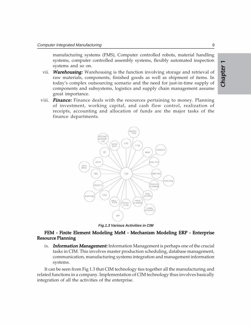
vii. Warehousing: Warehousing: Warehousing: Warehousing: Warehousing: Warehousing is the function involving storage and retrieval ofraw materials, components, finished goods as well as shipment of items. Intoday’s complex outsourcing scenario and the need for just-in-time supply ofcomponents and subsystems, logistics and supply chain management assumegreat importance.
viii. Finance:Finance:Finance:Finance:Finance: Finance deals with the resources pertaining to money. Planningof investment, working capital, and cash flow control, realization ofreceipts, accounting and allocation of funds are the major tasks of thefinance departments.
Fig.1.3 Various Activities in CIM
FEM - Finite Element Modeling MeM - Mechanism Modeling ERP - EnterpriseFEM - Finite Element Modeling MeM - Mechanism Modeling ERP - EnterpriseFEM - Finite Element Modeling MeM - Mechanism Modeling ERP - EnterpriseFEM - Finite Element Modeling MeM - Mechanism Modeling ERP - EnterpriseFEM - Finite Element Modeling MeM - Mechanism Modeling ERP - EnterpriseResource PlanningResource PlanningResource PlanningResource PlanningResource Planning
ix. Information Management: Information Management: Information Management: Information Management: Information Management: Information Management is perhaps one of the crucialtasks in CIM. This involves master production scheduling, database management,communication, manufacturing systems integration and management informationsystems.
It can be seen from Fig 1.3 that CIM technology ties together all the manufacturing andrelated functions in a company. Implementation of CIM technology thus involves basicallyintegration of all the activities of the enterprise.
10 CAD/CAM/CIM
1.6 DEVELOPMENT OF CIM
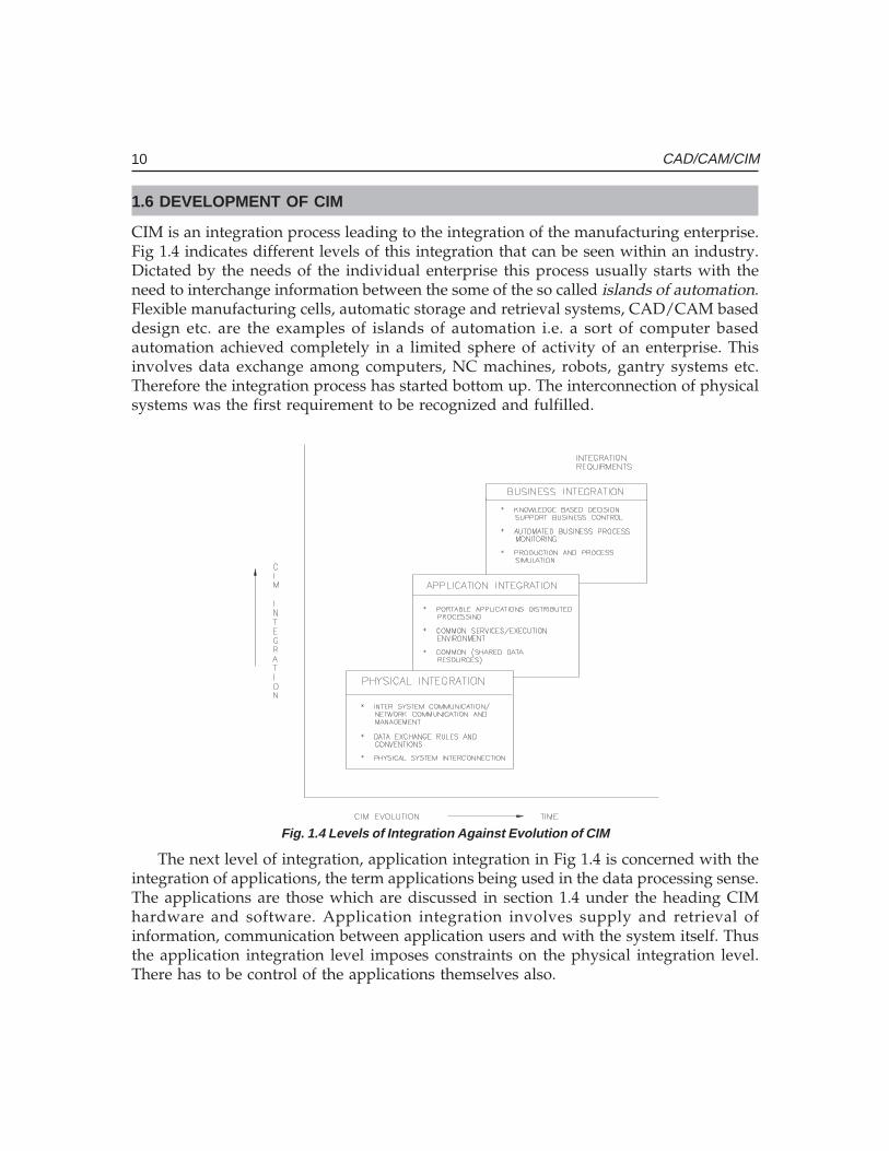
CIM is an integration process leading to the integration of the manufacturing enterprise.Fig 1.4 indicates different levels of this integration that can be seen within an industry.Dictated by the needs of the individual enterprise this process usually starts with theneed to interchange information between the some of the so called islands of automation.Flexible manufacturing cells, automatic storage and retrieval systems, CAD/CAM baseddesign etc. are the examples of islands of automation i.e. a sort of computer basedautomation achieved completely in a limited sphere of activity of an enterprise. Thisinvolves data exchange among computers, NC machines, robots, gantry systems etc.Therefore the integration process has started bottom up. The interconnection of physicalsystems was the first requirement to be recognized and fulfilled.
Fig. 1.4 Levels of Integration Against Evolution of CIM
The next level of integration, application integration in Fig 1.4 is concerned with theintegration of applications, the term applications being used in the data processing sense.The applications are those which are discussed in section 1.4 under the heading CIMhardware and software. Application integration involves supply and retrieval ofinformation, communication between application users and with the system itself. Thusthe application integration level imposes constraints on the physical integration level.There has to be control of the applications themselves also.
Ch
ap
ter
1C
ha
pte
r 1
Ch
ap
ter
1C
ha
pte
r 1
Ch
ap
ter
1
11Computer Integrated Manufacturing
The highest level of integration, business integration in Fig.1.4 is concerned with themanagement and operational processes of an enterprise. The management processprovides supervisory control of the operational process which in turn co-ordinates theday-to-day execution of the activities at the application level. The business integrationlevel therefore places constraints on the application level. This level offers considerablechallenge to the integration activity.
QUESTIONS
1. Describe the need for CIM and the issues addressed by CIM.2. What are the different types of manufacturing? Make an assessment of the extent
of computer control in specific cases of each types of manufacturing.3. What are the various activities of a manufacturing plant which can be carried out
through computer control?4. Discuss the main elements of CIM systems.5. Differentiate among physical integration, application integration and business
integration. Give specific examples of each.

This pageintentionally left
blank
�������������� �
�����������
������
CIM helps to reduce the product development cycle time. This chapter compares sequentialand concurrent approaches to product development. The importance of IT in realizing concurrencyis highlighted.
2.1 INTRODUCTION
The expectations of today’s customer include superior quality and performance, highertechnological capabilities and on time delivery. All these are to be provided at reducedcosts because of global competition faced by the manufacturing industries.
2.2 PRODUCT DEVELOPMENT CYCLE
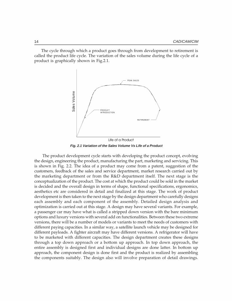
Industries have to continuously upgrade their products as well as introduce new productsin the market in order to retain as well as to increase their market share. The productdevelopment is the responsibility of the research and development (R&D) department ofa manufacturing company. When a product is initially introduced the sales volume will below. If the product is good and satisfies the customers, the sales will pick up. Sometimes,if there are any problems in the product the company will have to make changes orimprovements in the product which is a very expensive proposition. If the defect is seriousenough the company may have to recall an entire batch of products at enormous cost andloss of goodwill. The sales and service department usually takes care of attending to thecustomers’ problems. That is why manufacturers of automobiles, entertainment electronicgoods, fast moving consumer goods like washing machines and refrigerators etc haveelaborate sales and service network.
The sales volume will pick up gradually and peak after some time. The product willcontinue to sell for some time. The sales will then start gradually declining owing toavailability of better products in the market. It is time for the company to introduce a newand improved product in the market as well as to retire the old product. The companieswill usually advice the customers that the old product will be further supported by thesales and service department only for a limited period of time.
14 CAD/CAM/CIM
The cycle through which a product goes through from development to retirement iscalled the product life cycle. The variation of the sales volume during the life cycle of aproduct is graphically shown in Fig.2.1.
P R O D U C TIN TR O D U C T IO N
P E AK S AL E S
R E TIR E M E N T
��
les
Vo
lum
e
������������� �
Fig. 2.1 Variation of the Sales Volume Vs Life of a Product
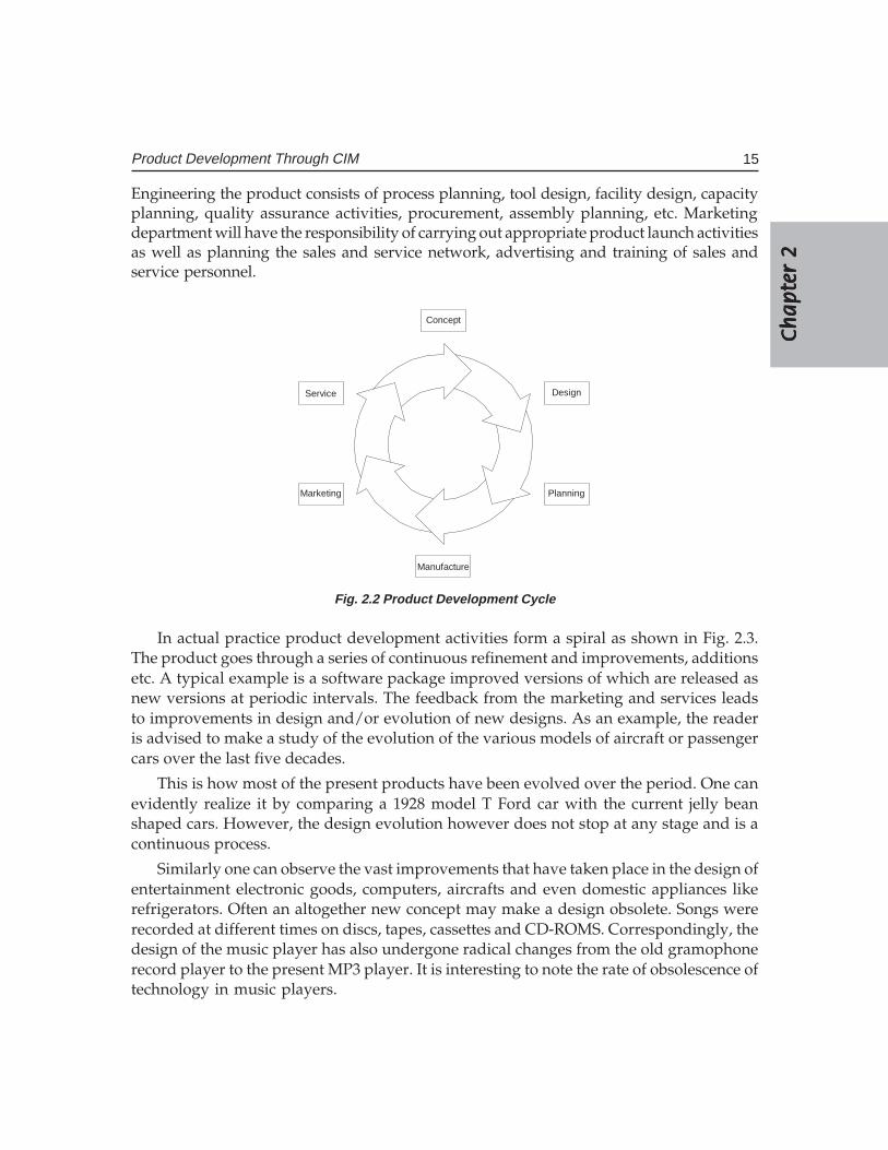
The product development cycle starts with developing the product concept, evolvingthe design, engineering the product, manufacturing the part, marketing and servicing. Thisis shown in Fig. 2.2. The idea of a product may come from a patent, suggestion of thecustomers, feedback of the sales and service department, market research carried out bythe marketing department or from the R&D department itself. The next stage is theconceptualization of the product. The cost at which the product could be sold in the marketis decided and the overall design in terms of shape, functional specifications, ergonomics,aesthetics etc are considered in detail and finalized at this stage. The work of productdevelopment is then taken to the next stage by the design department who carefully designseach assembly and each component of the assembly. Detailed design analysis andoptimization is carried out at this stage. A design may have several variants. For example,a passenger car may have what is called a stripped down version with the bare minimumoptions and luxury versions with several add on functionalities. Between these two extremeversions, there will be a number of models or variants to meet the needs of customers withdifferent paying capacities. In a similar way, a satellite launch vehicle may be designed fordifferent payloads. A fighter aircraft may have different versions. A refrigerator will haveto be marketed with different capacities. The design department creates these designsthrough a top down approach or a bottom up approach. In top down approach, theentire assembly is designed first and individual designs are done latter. In bottom upapproach, the component design is done first and the product is realized by assemblingthe components suitably. The design also will involve preparation of detail drawings.
Ch
ap
ter
2C
ha
pte
r 2
Ch
ap
ter
2C
ha
pte
r 2
Ch
ap
ter
2
15Product Development Through CIM
Engineering the product consists of process planning, tool design, facility design, capacityplanning, quality assurance activities, procurement, assembly planning, etc. Marketingdepartment will have the responsibility of carrying out appropriate product launch activitiesas well as planning the sales and service network, advertising and training of sales andservice personnel.
Concept
Design
Planning
Manufacture
Marketing
Service
Fig. 2.2 Product Development Cycle
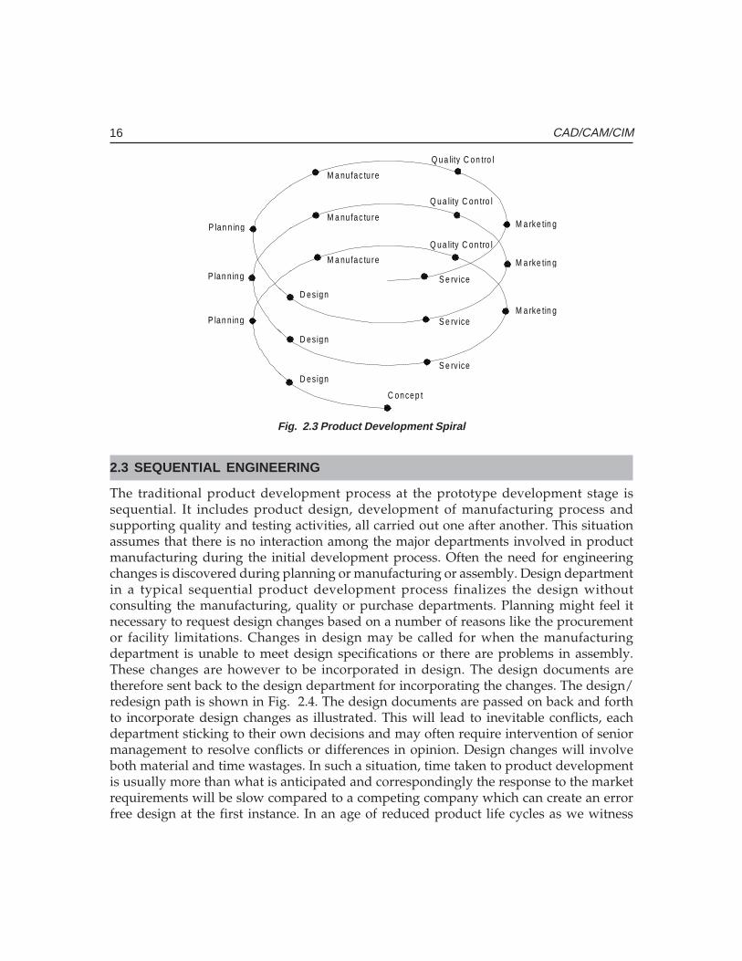
In actual practice product development activities form a spiral as shown in Fig. 2.3.The product goes through a series of continuous refinement and improvements, additionsetc. A typical example is a software package improved versions of which are released asnew versions at periodic intervals. The feedback from the marketing and services leadsto improvements in design and/or evolution of new designs. As an example, the readeris advised to make a study of the evolution of the various models of aircraft or passengercars over the last five decades.
This is how most of the present products have been evolved over the period. One canevidently realize it by comparing a 1928 model T Ford car with the current jelly beanshaped cars. However, the design evolution however does not stop at any stage and is acontinuous process.
Similarly one can observe the vast improvements that have taken place in the design ofentertainment electronic goods, computers, aircrafts and even domestic appliances likerefrigerators. Often an altogether new concept may make a design obsolete. Songs wererecorded at different times on discs, tapes, cassettes and CD-ROMS. Correspondingly, thedesign of the music player has also undergone radical changes from the old gramophonerecord player to the present MP3 player. It is interesting to note the rate of obsolescence oftechnology in music players.
16 CAD/CAM/CIM
C oncep t
D es ign
M a nu fac tu re
Q ua lity C on tro l
M a rke tin g
S e rv ice
P lan n ing
P lan n ing
P lan n ing
D es ign
D es ign
M a nu fac tu re
M a nu fac tu re
S e rv ice
S e rv ice
Q ua lity C on tro l
M a rke tin g
M a rke tin g
Q ua lity C on tro l
Fig. 2.3 Product Development Spiral
2.3 SEQUENTIAL ENGINEERING
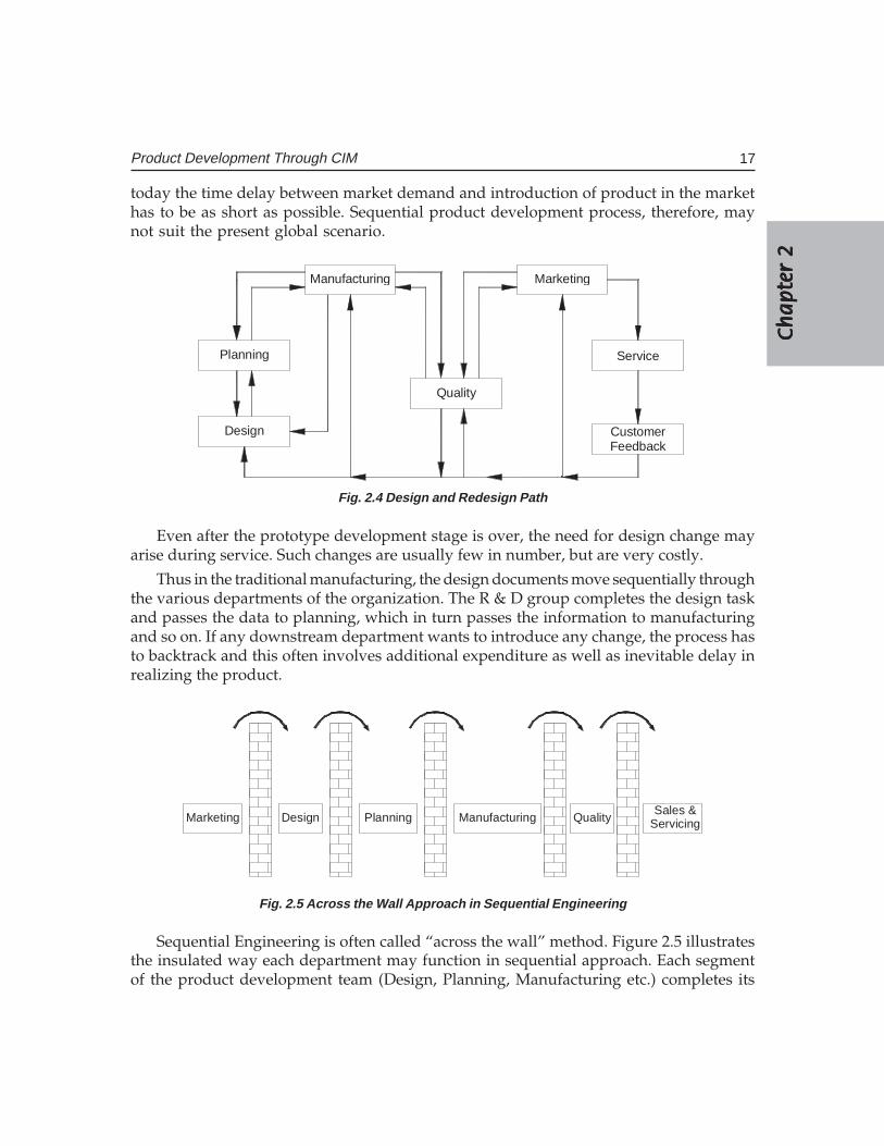
The traditional product development process at the prototype development stage issequential. It includes product design, development of manufacturing process andsupporting quality and testing activities, all carried out one after another. This situationassumes that there is no interaction among the major departments involved in productmanufacturing during the initial development process. Often the need for engineeringchanges is discovered during planning or manufacturing or assembly. Design departmentin a typical sequential product development process finalizes the design withoutconsulting the manufacturing, quality or purchase departments. Planning might feel itnecessary to request design changes based on a number of reasons like the procurementor facility limitations. Changes in design may be called for when the manufacturingdepartment is unable to meet design specifications or there are problems in assembly.These changes are however to be incorporated in design. The design documents aretherefore sent back to the design department for incorporating the changes. The design/redesign path is shown in Fig. 2.4. The design documents are passed on back and forthto incorporate design changes as illustrated. This will lead to inevitable conflicts, eachdepartment sticking to their own decisions and may often require intervention of seniormanagement to resolve conflicts or differences in opinion. Design changes will involveboth material and time wastages. In such a situation, time taken to product developmentis usually more than what is anticipated and correspondingly the response to the marketrequirements will be slow compared to a competing company which can create an errorfree design at the first instance. In an age of reduced product life cycles as we witness
Ch
ap
ter
2C
ha
pte
r 2
Ch
ap
ter
2C
ha
pte
r 2
Ch
ap
ter
2
17Product Development Through CIM
today the time delay between market demand and introduction of product in the markethas to be as short as possible. Sequential product development process, therefore, maynot suit the present global scenario.
Design
Planning
Manufacturing
Quality
Marketing
Service
CustomerFeedback
Fig. 2.4 Design and Redesign Path
Even after the prototype development stage is over, the need for design change mayarise during service. Such changes are usually few in number, but are very costly.
Thus in the traditional manufacturing, the design documents move sequentially throughthe various departments of the organization. The R & D group completes the design taskand passes the data to planning, which in turn passes the information to manufacturingand so on. If any downstream department wants to introduce any change, the process hasto backtrack and this often involves additional expenditure as well as inevitable delay inrealizing the product.
Marketing Design Planning Manufacturing QualitySales &
Servicing
Fig. 2.5 Across the Wall Approach in Sequential Engineering
Sequential Engineering is often called “across the wall” method. Figure 2.5 illustratesthe insulated way each department may function in sequential approach. Each segmentof the product development team (Design, Planning, Manufacturing etc.) completes its
18 CAD/CAM/CIM
task in isolation and passes over the documents to the next segment. There is no interactionamong the groups before the design is finalized. If a serious mistake in the product isdetected during testing, the revision process has to start from design, resulting in materialswastage and loss of time. In the context of extensive outsourcing, there is also need forintensive consultation between vendors and manufacturers.
2.4 CONCURRENT ENGINEERING
Concurrent engineering or Simultaneous Engineering is a methodology of restructuringthe product development activity in a manufacturing organization using a crossfunctional team approach and is a technique adopted to improve the efficiency ofproduct design and reduce the product development cycle time. This is also sometimesreferred to as Parallel Engineering. Concurrent Engineering brings together a widespectrum of people from several functional areas in the design and manufacture of aproduct. Representatives from R & D, engineering, manufacturing, materialsmanagement, quality assurance, marketing etc. develop the product as a team. Everyoneinteracts with each other from the start, and they perform their tasks in parallel. Theteam reviews the design from the point of view of marketing, process, tool design andprocurement, operation, facility and capacity planning, design for manufacturability,assembly, testing and maintenance, standardization, procurement of components andsub-assemblies, quality assurance etc as the design is evolved. Even the vendordevelopment department is associated with the prototype development. Any possiblebottleneck in the development process is thoroughly studied and rectified. All thedepartments get a chance to review the design and identify delays and difficulties.The departments can start their own processes simultaneously. For example, the tooldesign, procurement of material and machinery and recruitment and training ofmanpower which contributes to considerable delay can be taken up simultaneously asthe design development is in progress. Issues are debated thoroughly and conflicts areresolved amicably.
Concurrent Engineering (CE) gives marketing and other groups the opportunity toreview the design during the modeling, prototyping and soft tooling phases ofdevelopment. CAD systems especially 3D modelers can play an important role in earlyproduct development phases. In fact, they can become the core of the CE. They offer avisual check when design changes cost the least.
Intensive teamwork between product development, production planning andmanufacturing is essential for satisfactory implementation of concurrent engineering.The teamwork also brings additional advantages ; the co-operation between variousspecialists and systematic application of special methods such as QFD (Quality FunctionDeployment), DFMA (Design for Manufacture and Assembly) and FMEA (Failure Modeand Effect Analysis) ensures quick optimization of design and early detection of possiblefaults in product and production planning. This additionally leads to reduction in leadtime which reduces cost of production and guarantees better quality.
Ch
ap
ter
2C
ha
pte
r 2
Ch
ap
ter
2C
ha
pte
r 2
Ch
ap
ter
2
19Product Development Through CIM
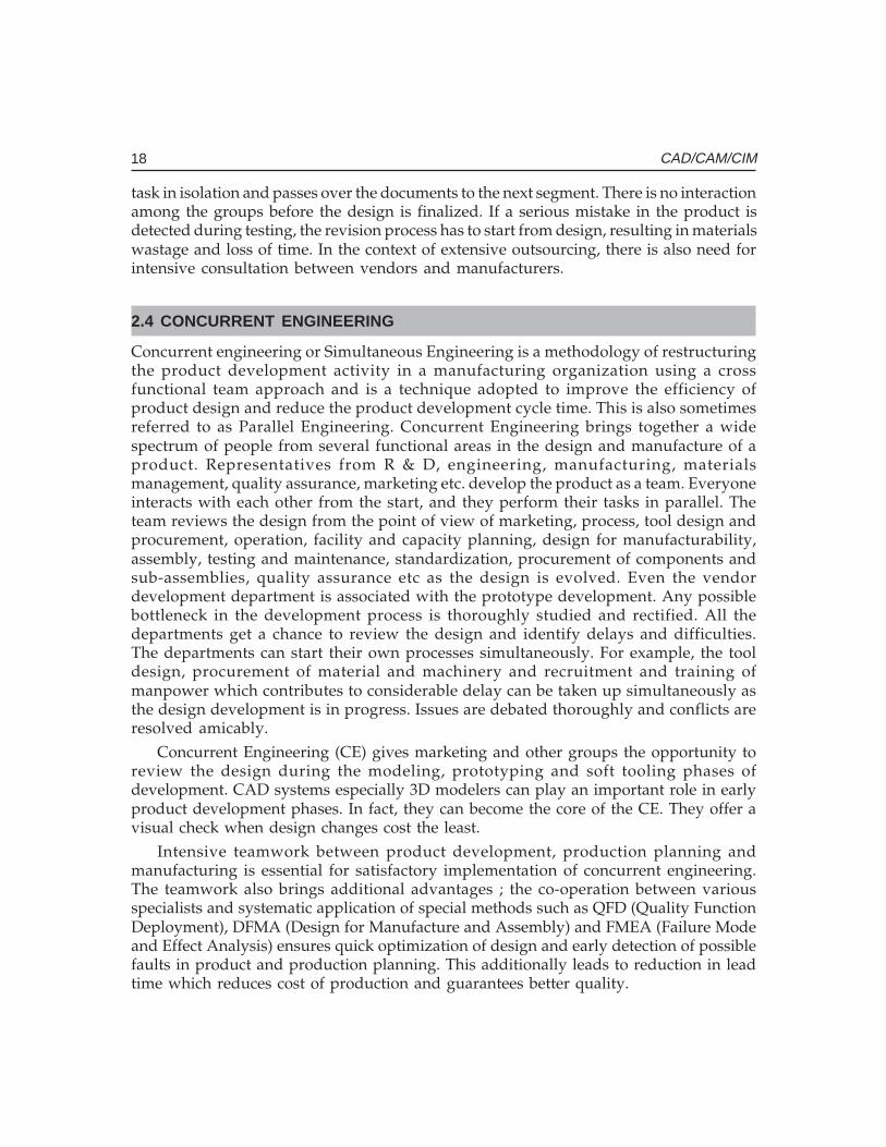
2.5 COMPARISON OF CONCURRENT ENGINEERING AND SEQUENTIALENGINEERING
A comparison of concurrent and sequential engineering based on cost is attempted inthis section. The distribution of the product development cost during the productdevelopment cycle is shown in Fig. 2.6. This figure shows that though only about 15%of the budget is spent at the time of design completion, whereas the remaining 85% isalready committed. The decisions taken during the design stage have an importantbearing on the cost of the development of the product. Therefore the development costand product cost can be reduced by proper and careful design. CE facilitates this. Thesignificantly large number of nonconformities detected in the later stages of productdevelopment cycle in sequential engineering results in large time and cost overrun.
D es ig n P la nn in g M an ufa ctu re
Cos
t
A s se m b ly Tes t
C os t Co m m itted
C as h F low
Fig. 2.6 Distribution of Product Development Cost
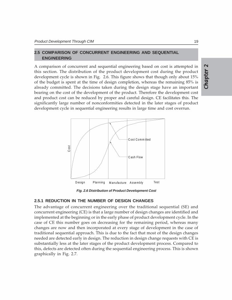
2.5.1 REDUCTION IN THE NUMBER OF DESIGN CHANGESThe advantage of concurrent engineering over the traditional sequential (SE) andconcurrent engineering (CE) is that a large number of design changes are identified andimplemented at the beginning or in the early phase of product development cycle. In thecase of CE this number goes on decreasing for the remaining period, whereas manychanges are now and then incorporated at every stage of development in the case oftraditional sequential approach. This is due to the fact that most of the design changesneeded are detected early in design. The reduction in design change requests with CE issubstantially less at the later stages of the product development process. Compared tothis, defects are detected often during the sequential engineering process. This is showngraphically in Fig. 2.7.
20 CAD/CAM/CIM
PRODUCT LIFE CYCLE
NU
MB
ER
OF
DE
SIG
N C
HA
NG
ES
Design Planning TestingManufacture Service
Fig. 2.7 Distribution of Design Changes Across the Life Cycle of a Product
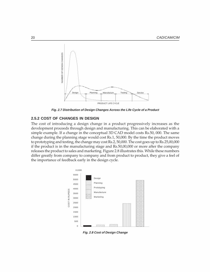
2.5.2 COST OF CHANGES IN DESIGNThe cost of introducing a design change in a product progressively increases as thedevelopment proceeds through design and manufacturing. This can be elaborated with asimple example. If a change in the conceptual 3D CAD model costs Rs.50, 000. The samechange during the planning stage would cost Rs.1, 50,000. By the time the product movesto prototyping and testing, the change may cost Rs.2, 50,000. The cost goes up to Rs.25,00,000if the product is in the manufacturing stage and Rs.50,00,000 or more after the companyreleases the product to sales and marketing. Figure 2.8 illustrates this. While these numbersdiffer greatly from company to company and from product to product, they give a feel ofthe importance of feedback early in the design cycle.
0
500
1000
1500
2000
2500
3000
3500
4000
4500
5000
5500
X1000
Design
Planning
Prototyping
Manufacture
Marketing
CO
ST
IN
RU
PE
ES
Fig. 2.8 Cost of Design Change
Ch
ap
ter
2C
ha
pte
r 2
Ch
ap
ter
2C
ha
pte
r 2
Ch
ap
ter
2
21Product Development Through CIM
2.5.3 HOLISTIC APPROACH TO PRODUCT DEVELOPMENTConcurrent engineering approach introduces a new philosophy in product development.No longer is product development considered the exclusive activity of the designdepartment. Participation of planning, manufacturing, quality, service, vendordevelopment and marketing personnel in the development process enables the crossfunctional team to view the development as a total responsibility and this results inbetter communication among the various departments.
2.5.4 ROBUST PRODUCTSConcurrent approach to product design results in products with fewer errors andtherefore avoids the loss of goodwill of the customers due to poorly engineered products.The entire product development team looks at each and every aspect of products – cost,specifications, aesthetics, ergonomics, performance and maintainability. The resultingproduct will naturally satisfy the customer.
2.5.5 REDUCTION IN LEAD TIME FOR PRODUCT DEVELOPMENTTime compression in product development is an important issue today. Concurrentengineering reduces the product development time significantly as the preparatory workin all downstream functions can take place concurrently with design. Elimination of theerrors in design appreciably reduces the possibility of time overrun, enabling thedevelopment schedule to be maintained.
2.6 IMPLEMENTATION OF CONCURRENT ENGINEERING
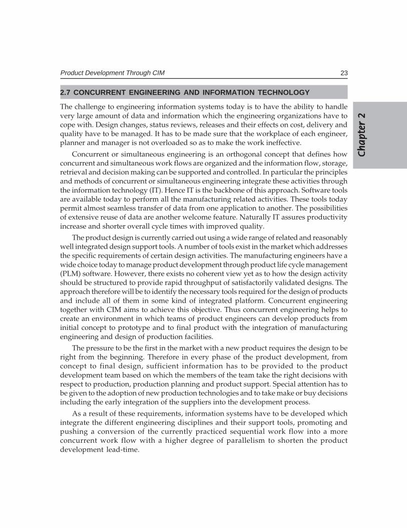
The cycle of engineering design and manufacturing planning involves interrelatedactivities in different engineering disciplines simultaneously, than sequentially as shownin Fig. 2.9 (A). In addition, the activities necessary to complete a particular task withina specific engineering discipline have to emerge wherever possible from their sequentialflow into a concurrent workflow with a high degree of parallelism as illustrated in Fig.2.9 (B). Concurrency implies that members of the multidisciplinary project team work inparallel. This also means that there is no strict demarcation of jobs among variousdepartments. The multi-disciplinary approach has the advantage of several inputs whichcan be focused effectively early in the design process. Presently engineering departmentsare practicing this approach but still with a high degree of manual involvement andredundancy. Planning scenarios experience a similar approach. One of the most criticallinks in the entire product life cycle, i.e. the close interaction between design andmanufacturing has been made possible in concurrent engineering. Thus the productdevelopment process has been freed from the large number of constraints arising fromthe limitations of the sequential engineering. This has changed the way manufacturersbring the products to market. For example, many manufacturers no longer view productdevelopment as a relay race in which marketing passes the baton to R &D, which inturn passes it to manufacturing. Representatives drawn from marketing, planning, design,
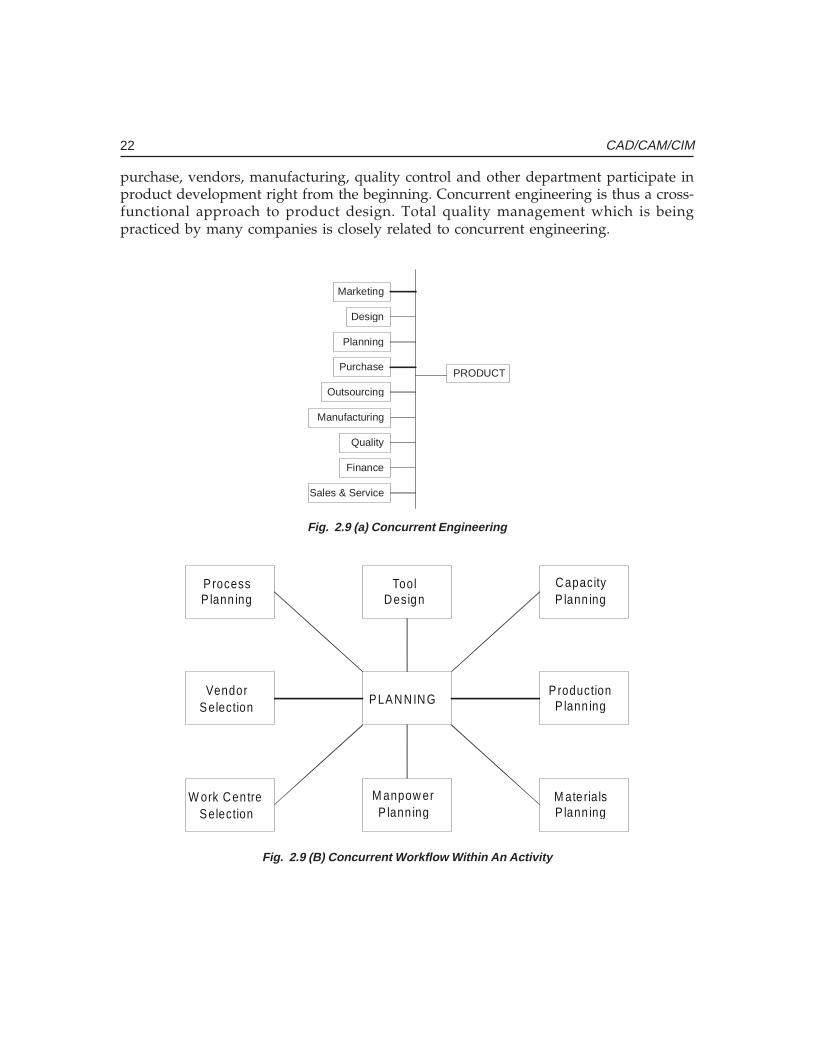
22 CAD/CAM/CIM
purchase, vendors, manufacturing, quality control and other department participate inproduct development right from the beginning. Concurrent engineering is thus a cross-functional approach to product design. Total quality management which is beingpracticed by many companies is closely related to concurrent engineering.
Marketing
Design
Planning
Purchase
Outsourcing
Manufacturing
Quality
Finance
Sales & Service
PRODUCT
Fig. 2.9 (a) Concurrent Engineering
ProcessP lann ing
VendorSelection
W ork Cen treSelection
PLANNING
CapacityP lann ing
ProductionP lann ing
M ate ria lsP lann ing
ToolDesign
M anpow erP lann ing
Fig. 2.9 (B) Concurrent Workflow Within An Activity
Ch
ap
ter
2C
ha
pte
r 2
Ch
ap
ter
2C
ha
pte
r 2
Ch
ap
ter
2
23Product Development Through CIM
2.7 CONCURRENT ENGINEERING AND INFORMATION TECHNOLOGY
The challenge to engineering information systems today is to have the ability to handlevery large amount of data and information which the engineering organizations have tocope with. Design changes, status reviews, releases and their effects on cost, delivery andquality have to be managed. It has to be made sure that the workplace of each engineer,planner and manager is not overloaded so as to make the work ineffective.
Concurrent or simultaneous engineering is an orthogonal concept that defines howconcurrent and simultaneous work flows are organized and the information flow, storage,retrieval and decision making can be supported and controlled. In particular the principlesand methods of concurrent or simultaneous engineering integrate these activities throughthe information technology (IT). Hence IT is the backbone of this approach. Software toolsare available today to perform all the manufacturing related activities. These tools todaypermit almost seamless transfer of data from one application to another. The possibilitiesof extensive reuse of data are another welcome feature. Naturally IT assures productivityincrease and shorter overall cycle times with improved quality.
The product design is currently carried out using a wide range of related and reasonablywell integrated design support tools. A number of tools exist in the market which addressesthe specific requirements of certain design activities. The manufacturing engineers have awide choice today to manage product development through product life cycle management(PLM) software. However, there exists no coherent view yet as to how the design activityshould be structured to provide rapid throughput of satisfactorily validated designs. Theapproach therefore will be to identify the necessary tools required for the design of productsand include all of them in some kind of integrated platform. Concurrent engineeringtogether with CIM aims to achieve this objective. Thus concurrent engineering helps tocreate an environment in which teams of product engineers can develop products frominitial concept to prototype and to final product with the integration of manufacturingengineering and design of production facilities.
The pressure to be the first in the market with a new product requires the design to beright from the beginning. Therefore in every phase of the product development, fromconcept to final design, sufficient information has to be provided to the productdevelopment team based on which the members of the team take the right decisions withrespect to production, production planning and product support. Special attention has tobe given to the adoption of new production technologies and to take make or buy decisionsincluding the early integration of the suppliers into the development process.
As a result of these requirements, information systems have to be developed whichintegrate the different engineering disciplines and their support tools, promoting andpushing a conversion of the currently practiced sequential work flow into a moreconcurrent work flow with a higher degree of parallelism to shorten the productdevelopment lead-time.
24 CAD/CAM/CIM
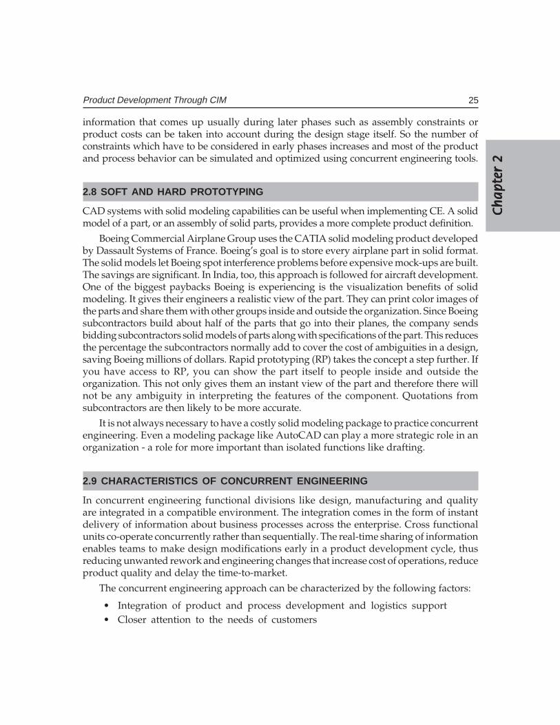
Presently, IT vendors offer a variety of tools for implementing some form of concurrentengineering. The tools can be broken into the following main technological groups:
• Knowledge based engineering, production tools and communication tools• Relational database management systems for data management• Work flow automation and product life cycle management (PLM) systems• Decision support systems• Enterprise resource planning systems
Table 2.1 shows a breakdown of the available technology in the market forimplementation of Concurrent Engineering.
TABLE 2.1 Software Technologies Available for Concurrent Engineering
Design Planning/Manufacture Visualization/Simulation
Solid modeling Process planning Factory Simulation
Surface modeling ERP Simulation software for-
Assembly modeling Generative machining • WeldingShop floor data collection • Casting
Sheet metal design Human machine interface • Forming
Drafting Job tracking • Forging
Tolerance analysis Work in process inventory • Plastic injection molding-
Mechanism design tracking • Robot operation
Finite Element analysis PDM, VPDM and PLMSoftware for- • Machining etc.
Harness design • EDM • Rapid Prototyping
Mold design • Wire EDM
Mold flow analysis • Press brake
Dynamic analysis • Grinding
Thermal analysis • Turret Punch Press
Composites design
Piping design
Optimization
Tool design
Standard part libraries
Through concurrent engineering, every aspect of the future product will be consideredat the same time. The individual departments representing different activities like design,process planning, production planning, subcontracting, purchase, manufacture, assemblyand quality assurance can make important contribution to product definition and preferablythese have to be incorporated in the design and in the early phases of life-cycle. Thus,
Ch
ap
ter
2C
ha
pte
r 2
Ch
ap
ter
2C
ha
pte
r 2
Ch
ap
ter
2
25Product Development Through CIM
information that comes up usually during later phases such as assembly constraints orproduct costs can be taken into account during the design stage itself. So the number ofconstraints which have to be considered in early phases increases and most of the productand process behavior can be simulated and optimized using concurrent engineering tools.
2.8 SOFT AND HARD PROTOTYPING
CAD systems with solid modeling capabilities can be useful when implementing CE. A solidmodel of a part, or an assembly of solid parts, provides a more complete product definition.
Boeing Commercial Airplane Group uses the CATIA solid modeling product developedby Dassault Systems of France. Boeing’s goal is to store every airplane part in solid format.The solid models let Boeing spot interference problems before expensive mock-ups are built.The savings are significant. In India, too, this approach is followed for aircraft development.One of the biggest paybacks Boeing is experiencing is the visualization benefits of solidmodeling. It gives their engineers a realistic view of the part. They can print color images ofthe parts and share them with other groups inside and outside the organization. Since Boeingsubcontractors build about half of the parts that go into their planes, the company sendsbidding subcontractors solid models of parts along with specifications of the part. This reducesthe percentage the subcontractors normally add to cover the cost of ambiguities in a design,saving Boeing millions of dollars. Rapid prototyping (RP) takes the concept a step further. Ifyou have access to RP, you can show the part itself to people inside and outside theorganization. This not only gives them an instant view of the part and therefore there willnot be any ambiguity in interpreting the features of the component. Quotations fromsubcontractors are then likely to be more accurate.
It is not always necessary to have a costly solid modeling package to practice concurrentengineering. Even a modeling package like AutoCAD can play a more strategic role in anorganization - a role for more important than isolated functions like drafting.
2.9 CHARACTERISTICS OF CONCURRENT ENGINEERING
In concurrent engineering functional divisions like design, manufacturing and qualityare integrated in a compatible environment. The integration comes in the form of instantdelivery of information about business processes across the enterprise. Cross functionalunits co-operate concurrently rather than sequentially. The real-time sharing of informationenables teams to make design modifications early in a product development cycle, thusreducing unwanted rework and engineering changes that increase cost of operations, reduceproduct quality and delay the time-to-market.
The concurrent engineering approach can be characterized by the following factors:
• Integration of product and process development and logistics support• Closer attention to the needs of customers
26 CAD/CAM/CIM
• Adoption of new technologies• Continuous review of design and development process• Rapid and automated information exchange• Cross functional teams• Rapid prototyping
2.10 KEY FACTORS INFLUENCING THE SUCCESS OF CE
Introduction of the concurrent engineering approach requires consideration of severalimportant factors. Starting CE with top management is not always ideal because manyunilateral initiatives from the top are likely to fail. Directives, training programs,reorganizations and pep talks, have been ineffective given the magnitude of change neededto implement CE.
CE can succeed if it comes from bottom up in the organization. If those at the bottomshare the concerns and agree that a problem exists, they are more likely to work togetherto solve it. In addition several problems are to be considered before introducing CE.
Despite the challenges a manufacturing company may meet, CE will result inconsiderable reduction in product development time. It should be realized that it maytake some time to make the members of the team to work together.
There are several examples of successful implementation of CE. Hewlett Packard isone such example. Its joint venture in Japan, Yokogawa Hewlett-Packard, reported amazingimprovements after implementing CE. Over a five year period, R & D’s cycle time decreasedby 35%, manufacturing costs declined 42%, inventory dropped 64% and field failure ratesfell by 60%. Meanwhile its market share tripled and profits doubled.
2.11 EXAMPLE OF CONCURRENT ENGINEERING
The story of the development of Neon Car in USA is a typical example of success ofconcurrent engineering. The planning of the car started in August 1990. For each majoritem product teams were made. Supporting teams were organized for such activities likedimension control, materials etc. The composition of a typical team included representativesfrom engineering, stamping, manufacturing processes, assembly, design, purchase, finance,product planning, materials handling and vendor development. Even suppliers were partof the product development team. Each team took approximately one year to complete atask. Subsequently process teams were organized to manufacture the product. Four monthsbefore the launch the process teams were converted into launch teams to successfullyintroduce the product in the market.
Another example for successful implementation of concurrent engineering is thedevelopment of Scooty moped and other products by TVS Motors Ltd. in India. Beforetaking up the design cross functional teams were formed to design and engineer the product.
Ch
ap
ter
2C
ha
pte
r 2
Ch
ap
ter
2C
ha
pte
r 2
Ch
ap
ter
2
27Product Development Through CIM
This reduced not only the product development time but also helped the manufacturerto introduce the quality product in the market.
2.12 TECHNIQUES TO IMPROVE MANUFACTURABILITY AND REDUCE LEAD TIME
The lead time for product development is the period of time between the go ahead signalto develop the product is given to the time when the product is ready to be released in themarket. Previous sections dealt with the various stages through which the developmentcycle has to go through. This product development lead time varies from product to product.Increase in global competition has compelled the manufacturers to progressively reducethe product development time. A set of tools have been developed to examine the designfrom different points of view like convenience in manufacture, assessment of risks in design,assembly, testing, servicing etc. These tools are generally labeled as “design for X”, whereX stands for cost, manufacture, assembly, testing, servicing etc. During as well as at theend of the process of design it is now customary to examine the designs based on certainspecific considerations. They are listed below:
1. Is the design of parts such that they can be easily manufactured on fabricated?This is referred to as design for manufacturing.
2. Is the product design such that the product can be assembled fast, easily andeconomically? Does the part design lend itself for automation of assembly?
3. Is the product design is such that the product can be tested easily? Many of theIC and microchip designs should facilitate easy testing.
4. Is the product design such that the product can be easily serviced? One of theplus points of a good design is its easy serviceability regardless whether it is acomputer or a washing machine.
5. Is the design carried out such that the cost is globally competitive? Today costof the product is a very important consideration. Most of the designs start froma targeted selling price and the corresponding production cost.
Five important considerations are mentioned above – manufacture, assembly, testing,service and cost. These can be a few other considerations too depending upon the product.
2.12.1 CURRENT APPROACH TO “DESIGN FOR X”There are some common guidelines which can be followed to satisfy the above fiveconsiderations. They are discussed below:
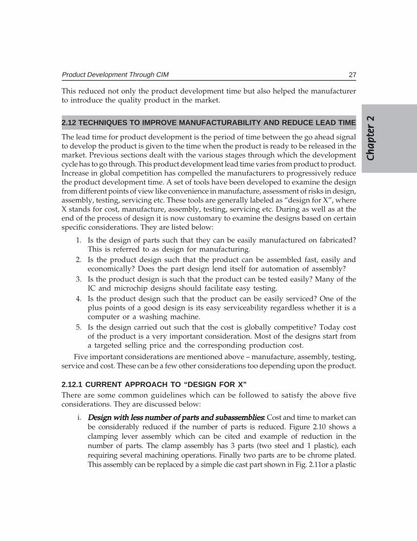
i. Design with less number of parts and subassembliesDesign with less number of parts and subassembliesDesign with less number of parts and subassembliesDesign with less number of parts and subassembliesDesign with less number of parts and subassemblies::::: Cost and time to market canbe considerably reduced if the number of parts is reduced. Figure 2.10 shows aclamping lever assembly which can be cited and example of reduction in thenumber of parts. The clamp assembly has 3 parts (two steel and 1 plastic), eachrequiring several machining operations. Finally two parts are to be chrome plated.This assembly can be replaced by a simple die cast part shown in Fig. 2.11or a plastic
28 CAD/CAM/CIM
clamp, thereby reducing the design and manufacturing cost. The alternative partsare available off the shelf. The new design is superior from the point of view ofmanufacturability. It is also cheaper and aesthetically superior. This trend isparticularly seen in aircraft and automotive industry. Increased use of sophisti-cated CNC machines like 5 axis machines and multitasking machines enables usto integrate several parts into a single monolithic part. This approach not onlydrastically reduces set up times but also improves the accuracy and makesavailable a part for assembly much earlier. A typical example where cost, qualityand performance could be improved through integration in ICs and VLSI chips.The concept of a system on a chip further reduced cost and improved reliability.
PART B(STEEL)
(STEEL)PART A
PART C(BAKELITE)
Fig. 2.10 Design of a Clamping Lever
Fig. 2.11 Improved Design of Clamping Lever
Introduction of high power series motors in spindle drives of CNC machines eliminatedthe need for a gear box, thereby not only improving performance but also reducing cost. Theintegral rotor spindles used in high speed CNC machines further reduced the number ofkinematic elements in main drive. The use of linear motors in reciprocating drives eliminatednot only ball screws and nuts but also paved way for increasing linear traverse speeds.
Ch
ap
ter
2C
ha
pte
r 2
Ch
ap
ter
2C
ha
pte
r 2
Ch
ap
ter
2
29Product Development Through CIM
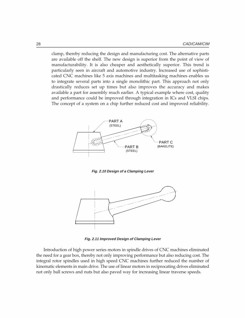
Another example of improvement of design is shown in Fig. 2.12. Fig. 2.12 (A) showsthe assembly which require the use of a screw driver. The number of parts required in 3.The assembly required aligning the screw and a screwdriver. The manufacture can besimplified using a rivet, thereby eliminating the threading operation (B). Making therivet integral with one part reduces the total number of parts to two (C). The design canbe further improved using a snap fit approach (D). An alternative design can be joiningthe two parts by a spot weld which may be cheaper than all the previous designs.
(A) (B)
(C) (D)
Fig. 2.12 Improvements in Design
ii. A product may be made in many variations to meet specific customer needsA product may be made in many variations to meet specific customer needsA product may be made in many variations to meet specific customer needsA product may be made in many variations to meet specific customer needsA product may be made in many variations to meet specific customer needsor end use:or end use:or end use:or end use:or end use: It is advisable to keep as many parts as standard to minimize productvariations. Automotive manufacturers adopt this approach very effectively. Theycreate many designs from the same platform and components often by addingoptions only. This keeps the cost of the product variations to a minimum.
iii. Fastener is a critical factor which makes easy assembly:Fastener is a critical factor which makes easy assembly:Fastener is a critical factor which makes easy assembly:Fastener is a critical factor which makes easy assembly:Fastener is a critical factor which makes easy assembly: A sound principle thatcould be followed is that minimum variety and number only should be used. Ifthere are socket head cap screws used, then use only one type so that a singleAllen key is necessary. This will reduce the assembly time by eliminating the needto change Allen keys and eliminate the need to keep inventory of a variety ofscrews while assemlling as well as the need to supply many tools for servicing.If possible, fastener could be altogether eliminated. Adhesive bonding and snapfit are examples. Both lend themselves to easy automation. The reader couldrealize the advantages of a snap fit assembly if a cell phone is examined.
30 CAD/CAM/CIM
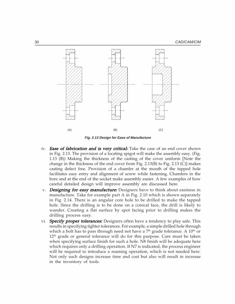
(A) (B) (C)
Fig. 2.13 Design for Ease of Manufacture
iv. Ease of fabrication and is very critical:Ease of fabrication and is very critical:Ease of fabrication and is very critical:Ease of fabrication and is very critical:Ease of fabrication and is very critical: Take the case of an end cover shownin Fig. 2.13. The provision of a locating spigot will make the assembly easy. (Fig.1.13 (B)) Making the thickness of the casting of the cover uniform [Note thechange in the thickness of the end cover from Fig. 2.13(B) to Fig. 2.13 (C)] makescasting defect free. Provision of a chamfer at the mouth of the tapped holefacilitates easy entry and alignment of screw while fastening. Chamfers in thebore and at the end of the socket make assembly easier. A few examples of howcareful detailed design will improve assembly are discussed here.
v. Designing for easy manufactureDesigning for easy manufactureDesigning for easy manufactureDesigning for easy manufactureDesigning for easy manufacture::::: Designers have to think about easiness inmanufacture. Take for example part A in Fig. 2.10 which is shown separatelyin Fig. 2.14. There is an angular core hole to be drilled to make the tappedhole. Since the drilling is to be done on a conical face, the drill is likely towander. Creating a flat surface by spot facing prior to drilling makes thedrilling process easy.
vi. Specify proper tolerancesSpecify proper tolerancesSpecify proper tolerancesSpecify proper tolerancesSpecify proper tolerances::::: Designers often have a tendency to play safe. Thisresults in specifying tighter tolerances. For example, a simple drilled hole throughwhich a bolt has to pass through need not have a 7th grade tolerance. A 10th or12th grade or general tolerance will do for this purpose. Care must be takenwhen specifying surface finish for such a hole. N8 finish will be adequate herewhich requires only a drilling operation. If N7 is indicated, the process engineerwill be required to introduce a reaming operation, which is not needed here.Not only such designs increase time and cost but also will result in increasein the inventory of tools.
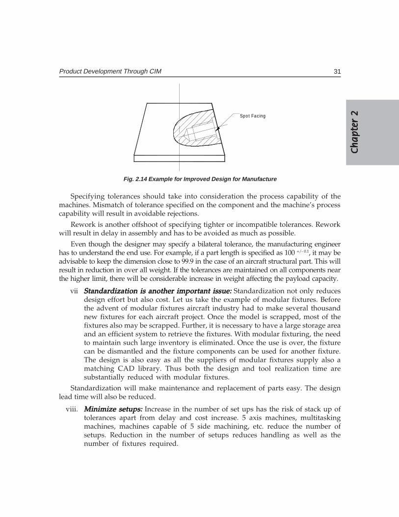
Ch
ap
ter
2C
ha
pte
r 2
Ch
ap
ter
2C
ha
pte
r 2
Ch
ap
ter
2
31Product Development Through CIM
Spo t Fac ing
Fig. 2.14 Example for Improved Design for Manufacture
Specifying tolerances should take into consideration the process capability of themachines. Mismatch of tolerance specified on the component and the machine’s processcapability will result in avoidable rejections.
Rework is another offshoot of specifying tighter or incompatible tolerances. Reworkwill result in delay in assembly and has to be avoided as much as possible.
Even though the designer may specify a bilateral tolerance, the manufacturing engineerhas to understand the end use. For example, if a part length is specified as 100 +/- 0.1, it may beadvisable to keep the dimension close to 99.9 in the case of an aircraft structural part. This willresult in reduction in over all weight. If the tolerances are maintained on all components nearthe higher limit, there will be considerable increase in weight affecting the payload capacity.
vii Standardization is another important issue:Standardization is another important issue:Standardization is another important issue:Standardization is another important issue:Standardization is another important issue: Standardization not only reducesdesign effort but also cost. Let us take the example of modular fixtures. Beforethe advent of modular fixtures aircraft industry had to make several thousandnew fixtures for each aircraft project. Once the model is scrapped, most of thefixtures also may be scrapped. Further, it is necessary to have a large storage areaand an efficient system to retrieve the fixtures. With modular fixturing, the needto maintain such large inventory is eliminated. Once the use is over, the fixturecan be dismantled and the fixture components can be used for another fixture.The design is also easy as all the suppliers of modular fixtures supply also amatching CAD library. Thus both the design and tool realization time aresubstantially reduced with modular fixtures.
Standardization will make maintenance and replacement of parts easy. The designlead time will also be reduced.
viii. Minimize setups:Minimize setups:Minimize setups:Minimize setups:Minimize setups: Increase in the number of set ups has the risk of stack up oftolerances apart from delay and cost increase. 5 axis machines, multitaskingmachines, machines capable of 5 side machining, etc. reduce the number ofsetups. Reduction in the number of setups reduces handling as well as thenumber of fixtures required.
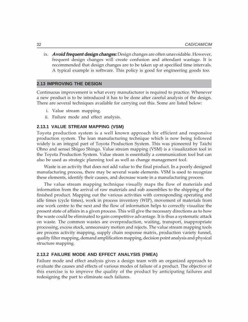
32 CAD/CAM/CIM
ix. Avoid frequent design changes:Avoid frequent design changes:Avoid frequent design changes:Avoid frequent design changes:Avoid frequent design changes: Design changes are often unavoidable. However,frequent design changes will create confusion and attendant wastage. It isrecommended that design changes are to be taken up at specified time intervals.A typical example is software. This policy is good for engineering goods too.
2.13 IMPROVING THE DESIGN
Continuous improvement is what every manufacturer is required to practice. Whenevera new product is to be introduced it has to be done after careful analysis of the design.There are several techniques available for carrying out this. Some are listed below:
i. Value stream mapping.ii. Failure mode and effect analysis.
2.13.1 VALUE STREAM MAPPING (VSM)Toyota production system is a well known approach for efficient and responsiveproduction system. The lean manufacturing technique which is now being followedwidely is an integral part of Toyota Production System. This was pioneered by TaichiOhno and sensei Shigeo Shingo. Value stream mapping (VSM) is a visualization tool inthe Toyota Production System. Value steam is essentially a communication tool but canalso be used as strategic planning tool as well as change management tool.
Waste is an activity that does not add value to the final product. In a poorly designedmanufacturing process, there may be several waste elements. VSM is used to recognizethese elements, identify their causes, and decrease waste in a manufacturing process.
The value stream mapping technique visually maps the flow of materials andinformation from the arrival of raw materials and sub assemblies to the shipping of thefinished product. Mapping out the various activities with corresponding operating andidle times (cycle times), work in process inventory (WIP), movement of materials fromone work centre to the next and the flow of information helps to correctly visualize thepresent state of affairs in a given process. This will give the necessary directions as to howthe waste could be eliminated to gain competitive advantage. It is thus a systematic attackon waste. The common wastes are overproduction, waiting, transport, inappropriateprocessing, excess stock, unnecessary motion and rejects. The value stream mapping toolsare process activity mapping, supply chain response matrix, production variety funnel,quality filter mapping, demand amplification mapping, decision point analysis and physicalstructure mapping.
2.13.2 FAILURE MODE AND EFFECT ANALYSIS (FMEA)Failure mode and effect analysis gives a design team with an organized approach toevaluate the causes and effects of various modes of failure of a product. The objective ofthis exercise is to improve the quality of the product by anticipating failures andredesigning the part to eliminate such failures.
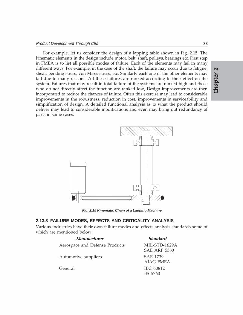
Ch
ap
ter
2C
ha
pte
r 2
Ch
ap
ter
2C
ha
pte
r 2
Ch
ap
ter
2
33Product Development Through CIM
For example, let us consider the design of a lapping table shown in Fig. 2.15. Thekinematic elements in the design include motor, belt, shaft, pulleys, bearings etc. First stepin FMEA is to list all possible modes of failure. Each of the elements may fail in manydifferent ways. For example, in the case of the shaft, the failure may occur due to fatigue,shear, bending stress, von Mises stress, etc. Similarly each one of the other elements mayfail due to many reasons. All these failures are ranked according to their effect on thesystem. Failures that may result in total failure of the systems are ranked high and thosewho do not directly affect the function are ranked low, Design improvements are thenincorporated to reduce the chances of failure. Often this exercise may lead to considerableimprovements in the robustness, reduction in cost, improvements in serviceability andsimplification of design. A detailed functional analysis as to what the product shoulddeliver may lead to considerable modifications and even may bring out redundancy ofparts in some cases.
Fig. 2.15 Kinematic Chain of a Lapping Machine
2.13.3 FAILURE MODES, EFFECTS AND CRITICALITY ANALYSISVarious industries have their own failure modes and effects analysis standards some ofwhich are mentioned below:
ManufacturerManufacturerManufacturerManufacturerManufacturer StandardStandardStandardStandardStandardAerospace and Defense Products MIL-STD-1629A
SAE ARP 5580Automotive suppliers SAE 1739
AIAG FMEAGeneral IEC 60812
BS 5760
34 CAD/CAM/CIM
Automotive manufacturers like Daimler Chrysler, FORD and General Motors usetheir own FMEA methodologies. There are other standards like RAC FMD – 97 andHAZOP (Hazards and Operability) data. FMD-97 data specifies component failure modesand the percentages of time that these modes are responsible for failures HAZOP softwarecan be used for identifying potential hazards and operability problems caused bydeviations from the design intent both the new and existing processes.
2.14 TAGUCHI METHOD FOR ROBUST DESIGN
This method is eminently suitable for improving the quality of products and processesmaking them more robust. The performance of a product or process may be influenced byseveral parameters. Let us take the simple example of optimizing the life of a simple helicalreduction gear box. There are several parameters influencing the performance of a gear:
i. Number of teethii. Face width ratio
iii. Addendum modificationiv. Surface hardness
It may be desirable that certain parameters like centre distance, reduction ratio, materialetc. have to be kept constant. A study can be conducted to evaluate these parameters attwo or three levels. A suitable combination of these parameters can be selected usingstandard orthogonal arrays like L8 or L9. This will minimize the number of experiments tobe performed. Using analysis of variance or signal to noise ratio it is possible to determinethe most important parameter and the values of the parameters.
The process of optimizing the processes is similar. An example is taken from the directmetal laser sintering process. The process variables are laser power, layer thickness, sinteringspeed, hatch interval, pre-contouring, post-contouring, hatch type size of metal powderetc. Laser power, layer thickness and powder size may be constant for a given machine.The parameters that can be varied in the study are then sintering, pre-contouring, post-contouring, hatch interval and hatch type. What is of interest is the combination of processparameters that leads to best strength, highest accuracy and best surface finish. Trials canbe conducted using a standard experimental pattern suggested by Taguchi. The study canlead to better understanding of the process and the interdependence of parameters andoften can yield valuable information to improve the process further.
2.15 VALUE ENGINEERING
Value Engineering is another useful tool to improve the products and processes. The termvalue is defined as the ratio of function or performance to cost. The purpose of valueengineering to maximize the value of the product by improving its functional capability.This is achieved by reducing the cost of each function without sacrificing the function at all.
Ch
ap
ter
2C
ha
pte
r 2
Ch
ap
ter
2C
ha
pte
r 2
Ch
ap
ter
2
35Product Development Through CIM
The value of the product can be classified into two:
i. The ability of the product to satisfy the needs of the user.ii. Esteem value which is a measure of the desirability of the product.The most important component of value engineering is defining its function. Each
component of the product and the product itself is given a functional statement and thatfunction is assigned a numerical value. Cost of that function is determined on the basis ofmanufacturing costs and other components of the costs. This is perhaps the most difficultpart of value engineering.
2.16 PRODUCT LIFE CYCLE MANAGEMENT
Manufacturing, very often has been based on the concept of make to stock. This will howevercontinue in the case of many products like machine tools, electronic entertainment productsetc. However, the preferences of customers are now being given more importance. Manymanufacturers follow the concepts of assembled to order or engineered to order. In theformer, the manufacturer assembles a product to the specific requirements of the customer.For example, assume that a customer orders a car with windscreen wipers which cansense the rain and automatically start or stop wipers. This requirement is passed on to theassembly line of the car to assemble a car conforming to the customer’s requirements. Insuch cases, the manufacturer offers a basket of options and assembles a product to meetthe specifications of the buyer. In the case of engineered to order products, right fromdesign, the product is engineered to meet the specifications of the customer. Whatever bethe case, a manufacturer has to consider the following issues:
(i) Cost efficiency:Cost efficiency:Cost efficiency:Cost efficiency:Cost efficiency: Ability to manufacture a product at a predefined cost that itcould be profitably sold.
(ii) Product quality:Product quality:Product quality:Product quality:Product quality: Maintain a quality level comparable, if not better than competitor’sproducts and continuously improve the quality.
(iii) Design for manufacture and assembly:Design for manufacture and assembly:Design for manufacture and assembly:Design for manufacture and assembly:Design for manufacture and assembly: Design the product in such a way that theproduct can be manufactured, and assembled with case.
(iv) Time to market: Time to market: Time to market: Time to market: Time to market: Agility to sense the market requirements and bring a newproduct into the market ahead of the competitors. This means that manufacturersmust be able to get it right first time every time. There is very little scope for costlyiterations.
(v) Serviceability:Serviceability:Serviceability:Serviceability:Serviceability: Engineer a product in such a manner that in case there is amalfunctioning, it can be easily attended to. It must also be possible to refurbishif necessary after the lapse of a few years, recycle part of the product and retunethe product at an appropriate stage when it is technologically obsolete.
The concept of making all parts or subassemblies of a product under one roof isgiving way to massive outsourcing. The design and manufacturing activity is thus carriedout not in one location but in many locations distributed all around the world. The
36 CAD/CAM/CIM
manufacturing value chain is more complex and in order to efficiently manufacture aproduct today depends much on a suite of software called product life cycle management(PLM). This software views the entire life cycle of a product as a process that can bemanaged, measured, monitored and modified to achieve continuous improvement.
PLM is a bundle of technologies that tie together all product related data. Basicallyall engineering activities related to manufacture are role based. For example, designerswould like to use CAD models for early analysis, simulation and optimization. A processplanning engineer would like to access the features of the geometry of the part. Amanufacturing engineer will be interested to study the easy access of the tool to machinedsurfaces in order to minimize the number of setups and reduce the throughput time. Amarketing engineer has no use for the above information. He may be interested only inthe shape description through a VRML file. Thus each of the manufacturing roles isinterested in only a part of the product database and the best technologies available toprocess the database to carry out his assigned task. More and more manufacturers todayoutsource a part or their full requirements. Many outsourced components go into designswhen manufactured should reach the market with minimum or no flaws.
Another critical requirement is in managing design changes. These are inevitabletoday, as all products should respond to market changes. Such product changes shouldbe reflected in all the drawings and bill of materials concerned so that the design changescan be seamlessly incorporated. The scope of the PLM software is such that manufacturersacquire the capability to collaborate internally (within the organization) and externally(outsourcing partners or vendors) collaborate on product development, manufacture,market and service till the retirement of the product, consistently maintaining the highestpossible efficiency throughout the value chain. A significant advantage of PLM packagesis that they are Internet based and therefore it can enable the manufacturers to changetheir business models. The importance of logistics and supply chain management intoday’s global manufacturing scenario needs no emphasis. Equally important areenterprise resource planning, (ERP) and customer relationship management (CRM).Interoperability is the order of the day. PLM does provide this functionality.
PLM permits the product data to be visualized in several forms:
• 3D CAD Models• Bill of Materials• Schematic Diagrams• Schedules• Forecasts.
2.16.1 PLM SOFTWARESThere are a number of vendors of PLM software today.
(i) PTC(ii) SDRC/EDS
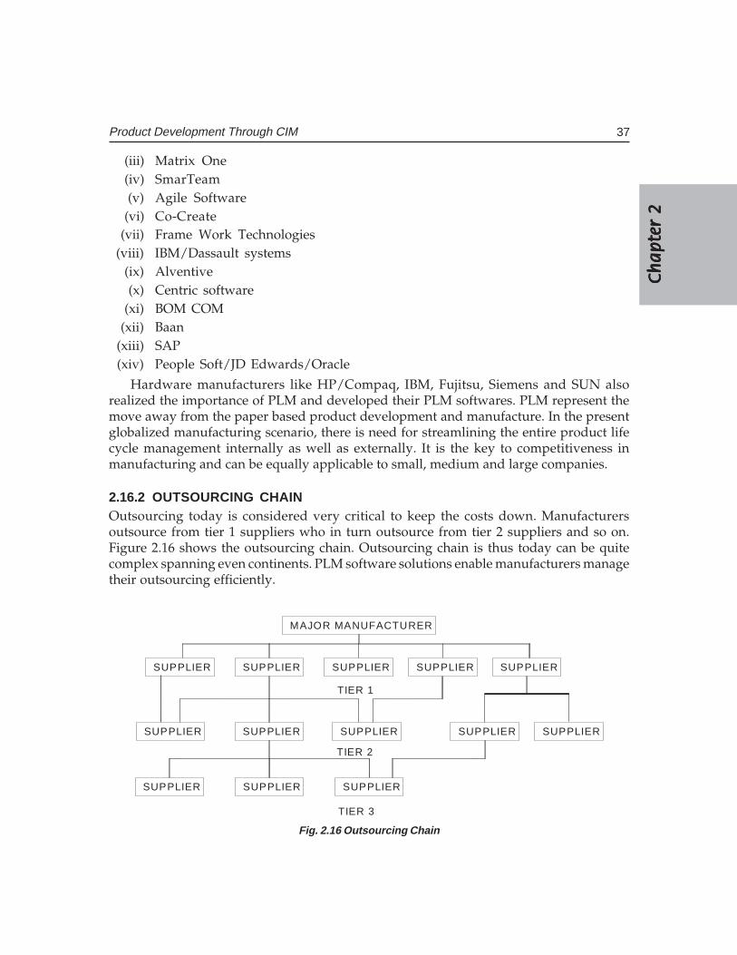
Ch
ap
ter
2C
ha
pte
r 2
Ch
ap
ter
2C
ha
pte
r 2
Ch
ap
ter
2
37Product Development Through CIM
(iii) Matrix One(iv) SmarTeam(v) Agile Software
(vi) Co-Create(vii) Frame Work Technologies
(viii) IBM/Dassault systems(ix) Alventive(x) Centric software
(xi) BOM COM(xii) Baan
(xiii) SAP(xiv) People Soft/JD Edwards/Oracle
Hardware manufacturers like HP/Compaq, IBM, Fujitsu, Siemens and SUN alsorealized the importance of PLM and developed their PLM softwares. PLM represent themove away from the paper based product development and manufacture. In the presentglobalized manufacturing scenario, there is need for streamlining the entire product lifecycle management internally as well as externally. It is the key to competitiveness inmanufacturing and can be equally applicable to small, medium and large companies.
2.16.2 OUTSOURCING CHAINOutsourcing today is considered very critical to keep the costs down. Manufacturersoutsource from tier 1 suppliers who in turn outsource from tier 2 suppliers and so on.Figure 2.16 shows the outsourcing chain. Outsourcing chain is thus today can be quitecomplex spanning even continents. PLM software solutions enable manufacturers managetheir outsourcing efficiently.
MAJOR MANUFACTURER
SUPPLIER SUPPLIER SUPPLIER SUPPLIERSUPPLIER
SUPPLIER SUPPLIER SUPPLIER SUPPLIER SUPPLIER
SUPPLIER SUPPLIER SUPPLIER
TIER 1
TIER 2
TIER 3
Fig. 2.16 Outsourcing Chain
38 CAD/CAM/CIM
2.16.3 PLM AND CONCURRENT ENGINEERINGPLM helps the product developers to try many solutions within the same developmenttime window through efficient collaboration and communication among various partnersinvolved in development. PLM enables all stakeholders to provide their inputs early inthe development cycle so that the high costs associated with design changes introducedlater in the development cycle can be eliminated. This will also reduce the time overrunsignificantly as the errors that cripple production and delivery processes are avoided. PLMextends the power of collaboration to other outside entities like business partners,distributors, customers, analysts etc. Since product information is available early in thedevelopment cycle, numerous product readiness activities like creation of product literature,and other product promotion efforts and training could be taken up concurrently, withinthe limited time to market window.
2.16.4 OTHER ADVANTAGES OF PLMApart from evolving new business models, PLM has enabled manufacturers to reduce thetime to market new products, design products which could perform better and therebyfacilitate product innovation improve manufacturability and quality, reduce costs throughreduction of wastage and make collaborative design and manufacture seamless and efficientwithin and outside the organization. Customer satisfaction is ensured by capturing theproduct related expectations and preferences of the targeted customers and align the designto satisfy these requirements. This also helps to deliver product enhancements that stretchthe product life cycle.
2.16.5 COMPONENTS OF PLM SOFTWAREA PLM software suite many consists of a number of modules. These are discussed below:
(i) Engineering Engineering Engineering Engineering Engineering dddddesign: esign: esign: esign: esign: Multiple CAD/CAE/CAM softwares are used bydesigners to create designs. These are used for product design which includescreation of designs, release of designs, design management, engineeringprocess management, digital validation, change management and designcollaboration in multi-sites. Design analysis also incorporate creation ofvirtual prototypes which can be used to check interference as well asclearances, ergonomic and aesthetic studies, convenience for assembly anddisassembly and fit and function studies. PLM software converts nativeCAD files into a suitable neutral format so that extended product teams canstudy components and assemblies.
(ii) Knowledge management and process automation:Knowledge management and process automation:Knowledge management and process automation:Knowledge management and process automation:Knowledge management and process automation: PLM allows the user to capture,integrate, secure and control all product, process manufacturing and serviceknowledge in a single repository. Design capture, documentation, vaulting,versioning control, product structure and configuration management, etc.facilitate effective knowledge management. Visualization and collaborationcapabilities enable team members to view the digital mock up or exchange
Ch
ap
ter
2C
ha
pte
r 2
Ch
ap
ter
2C
ha
pte
r 2
Ch
ap
ter
2
39Product Development Through CIM
product representations. Other facilities provided by PLM packages are processmanagement, change management, parts classification, release management,and version management.
(iii) Product visualization: Product visualization: Product visualization: Product visualization: Product visualization: Aesthetics and ergonomics play vital roles in the marketacceptability of a product. Sales and marketing organizations, suppliers,customers etc. are part of the extended life cycle family and they have animportant role in configuring the product at the conceptual design stage.Visualization also includes 2D/3D markup, dynamic cross sectioning andmeasurements capabilities. It must be possible to assemble an advanced digitalmockup to carry out various analyses on the whole product.
(iv) Real time collaboration: Real time collaboration: Real time collaboration: Real time collaboration: Real time collaboration: Secure, adaptive and user friendly real time collaborativeenvironment is required to facilitate rapid sourcing, carry out concept studies,program reviews, design reviews, and for incorporating engineering changes.
(v) Managing life cycle projects: Managing life cycle projects: Managing life cycle projects: Managing life cycle projects: Managing life cycle projects: Creating, maintaining and monitoring projectschedules that reflect tasks, dependencies, milestones and start to finish datesare very important to carry out a successful project. Project tracking andreporting capabilities are useful for executives to create updates. Emails andPOP up notifications, event based notices etc. enable the executives to take careof trouble spots. This will also help to make reviews and cost control effective.
(vi) Assessing and capturing customer requirements: Assessing and capturing customer requirements: Assessing and capturing customer requirements: Assessing and capturing customer requirements: Assessing and capturing customer requirements: Understanding target marketsand the needs of the customers are key elements in the success of a product.
(vii) Supply Supply Supply Supply Supply ccccchain hain hain hain hain mmmmmanagement: anagement: anagement: anagement: anagement: Sourcing is an important activity and efficientmanagement of sourcing plays an important role in productivity, cost controland shortening time to market. Efficient and cost effective sourcing is veryessential to retain the competitive edge in the global market. PLM softwareintegrates the procurement related processes with the rest of engineering andproduct development activities. PLM software enables the suppliers to appreciatetheir role in the product development cycle. The suppliers can thus fullyunderstand the manufacturer’s requirements, supply chain needs and productdefinitions. The product development team can assess through the variousfunctionalities of this module each prospective supplier in terms of designcontent, cost efficiency and product quality as well as supplier’s capabilities.
(viii) Manufacturing: Manufacturing: Manufacturing: Manufacturing: Manufacturing: In addition to the physical factory PLM helps to build acompany a digital factory and creates the data to feed all the downstreammanufacturing execution system using the data from the product definitionprocess. The manufacturing module performs the following functions:
Part manufacturing planningAssembly process planningFactory layout and analysisRobot programming and simulationWorker safety and ergonomic studiesComputer aided manufacturing
40 CAD/CAM/CIM
(ix) Servicing capability:Servicing capability:Servicing capability:Servicing capability:Servicing capability: The processes associated with maintaining, repairing andoverhauling machinery and equipment are digitally enabled by this module.Service manuals, repair and overhaul procedure, bill of materials, changehistories, compliance and regulatory standards, equipment availability, time torepair and optimization of the cost of servicing are some of the componentsof this module.
QUESTIONS
1. Discuss the stages in the product life cycle and the importance of each stage.2. List and describe various activities involved in product development.3. Study an industrial product and discuss how the product is evolved and
perfected continuously.4. What are the drawbacks of sequential engineering in handling design change
requests?5. Discuss the significance of concurrent engineering approach in limiting design
changes.6. How does IT facilitate concurrent engineering?7. Discuss how CIM can act as an enabling technology for concurrent engineering.8. How will concurrent engineering will help to reduce product development time?9. Discuss important guidelines to examine the manufacturability of a design.
10. What is meant by robust design?11. What are the techniques commonly used to improve a design?12. Describe how the Taguchi technique can be used to evolve a robust design.13. What is meant by value stream mapping? How is it useful in product development?14. Discuss the application of Failure Mode and Effect Analysis to improve a design.15. What is PLM?16. What are the core issues addressed by PLM?17. How does PLM help in outsourcing?18. What are the components of PLM software?
������������
��� �����������
�������
The display of the drawing or the geometric model of the component in CAD uses thetechnology of computer graphics. The techniques of raster technology, scan conversion,clipping, removal of hidden lines and hidden surfaces, color, shading and texture, necessaryto understand the complex process of computer graphics are briefly dealt in this chapter.
3.1 INTRODUCTION
Traditionally drawings are prepared on plane drawing sheets. This has several limitations.The sketches have to be made only in two dimensions. Though the depth can be representedby pictorial projections like isometric and perspective projections, the projections have tobe necessarily reduced to two dimensions.
Use of computer graphics has opened up tremendous possibilities for the designer.Some of them are listed below:
• The object is represented by its geometric model in three dimensions (X, Y and Z).• The mathematical representation reduces creation of views like orthographic,
isometric, axonometric or perspective projections into simple viewingtransformations.
• Though the size of the screen is limited, there is no need to scale the drawings.• Drawings can be made very accurate.• The geometric models can be represented in color and can be viewed from any
angle.• Sections can be automatically created.• The associativity ensures that any change made in one of the related views will
automatically reflect in other views.• Revision and revision control are easy.• Drawings (geometric models) can be modified easily.• More important than all, drawings can be reused conveniently.• Storage and retrieval of drawings are easy.
42 CAD/CAM/CIM
Modern computer graphics displays are simple in construction. They consist of basicallythree components.
i. Monitorii. Digital Memory or Frame Buffer
iii. Display Controller
Most of the computer graphics displays use raster CRT which is a matrix of discretecells each of which can be made bright. A graphic entity like line or circle is represented asa series of “points or dots” on the screen. Therefore, it is called as a point plotting device.
The video display screen is divided into very small rectangular elements called a pictureelement or pixel. This happens to be the smallest addressable screen element. Graphicimages are formed by setting suitable intensity and color to the pixels which compose theimage. Depending upon the resolution screens may have varying number of pixels. Forexample, an SVGA monitor with a resolution of 1024 x 768 will have 1024 pixels in everyrow (X - direction) and 768 pixels in every column (Y-direction). Monitors of larger sizewill have resolution of 1024 x 1024 or more. A raster scan system displays the image on aCRT in a certain fixed sequence.
The refresh rate is the number of complete images or frames scanned per second. Inthe case of interlaced refresh cycle odd numbered raster lines are refreshed during 1/60thof a second. Even numbered raster lines are refreshed during the next 1/60th of a second.In non-interlaced displays, all lines are refreshed in 1/60th of a second. The quality of non-interlaced display is hence, superior. These systems, however, require expensive framebuffer memory and display controller.
3.2 GRAPHIC PRIMITIVES
A drawing is created by an assembly of points, lines, arcs, circles. For example, drawingshown in Fig 3.1 consists of several entities. In computer graphics also drawings are createdin a similar manner. Each of these is called an entity. The drawing entities that a user mayfind in a typical CAD package include :
pointlineconstruction line, multi-line, polylinecirclesplinearcellipsepolygonrectangle
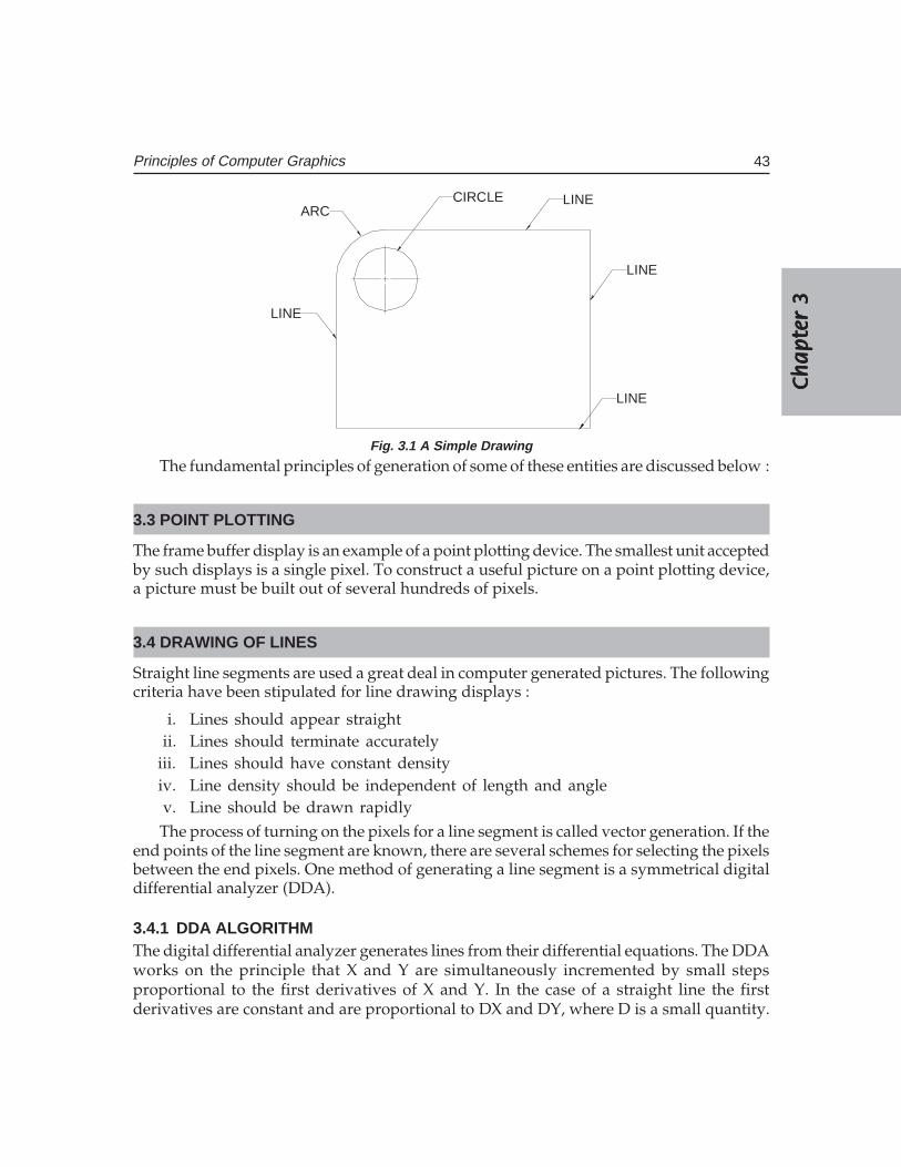
Ch
ap
ter
3C
ha
pte
r 3
Ch
ap
ter
3C
ha
pte
r 3
Ch
ap
ter
3
43Principles of Computer Graphics
ARCCIRCLE LINE
LINE
LINE
LINE
Fig. 3.1 A Simple Drawing
The fundamental principles of generation of some of these entities are discussed below :
3.3 POINT PLOTTING
The frame buffer display is an example of a point plotting device. The smallest unit acceptedby such displays is a single pixel. To construct a useful picture on a point plotting device,a picture must be built out of several hundreds of pixels.
3.4 DRAWING OF LINES
Straight line segments are used a great deal in computer generated pictures. The followingcriteria have been stipulated for line drawing displays :
i. Lines should appear straightii. Lines should terminate accurately
iii. Lines should have constant densityiv. Line density should be independent of length and anglev. Line should be drawn rapidlyThe process of turning on the pixels for a line segment is called vector generation. If the
end points of the line segment are known, there are several schemes for selecting the pixelsbetween the end pixels. One method of generating a line segment is a symmetrical digitaldifferential analyzer (DDA).
3.4.1 DDA ALGORITHMThe digital differential analyzer generates lines from their differential equations. The DDAworks on the principle that X and Y are simultaneously incremented by small stepsproportional to the first derivatives of X and Y. In the case of a straight line the firstderivatives are constant and are proportional to DX and DY, where D is a small quantity.
44 CAD/CAM/CIM
In the real world of limited precision displays, addressable pixels only must begenerated. This can be done by rounding to the next integer after each incremental step.After rounding, a pixel is displayed at the resultant X and Y locations. An alternative torounding is the use of arithmetic overflow. X and Y are kept in registers that have integerand fractional parts. The incrementing values which are less than unity are repeatedlyadded to the fractional part and whenever the result overflows the corresponding integerpart is incremented. The integer parts of X and Y are used to plot the line. This wouldnormally have the effect of truncating. The DDA is therefore initialized by adding 0.5 ineach of the fractional parts to achieve true rounding.
The symmetrical DDA generates reasonably accurate lines since a displayed pixel isnever away from a true line by half the pixel unit. A Pascal procedure for a simple DDA isgiven below :
Procedure DDA (X1, Y1, X2, Y2 : integer) ;
length : var ;
i : integer;
X, Y, X-incr, Y-incr : real ;
begin
length : = abs (X2– X1) ;
if abs (Y2–Y1) < length then length: = abs (Y2–Y1);
X - incr : = (X2 – X1) /length ;
Y - incr : = (Y2 – Y1) /length ;
X : = X1 + 0.5 ; Y = Y1 + 0.5 ;
for i : = 1 to length do
begin
plot (trunc (X) ; trunc(Y) ;
X : = X + X - incr ;
Y : = Y + Y - incr ;
end;
end.
3.4.2 EXAMPLETo draw a straight line from connecting two points (2, 7) and (15, 10)
X1 = 2, X2 = 15 abs(X2 – X1) = 13
Y1 = 7, Y2 = 10 abs(Y2 – Y1) = 3
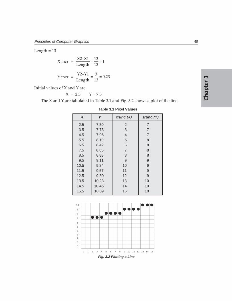
Ch
ap
ter
3C
ha
pte
r 3
Ch
ap
ter
3C
ha
pte
r 3
Ch
ap
ter
3
45Principles of Computer Graphics
Length = 13
X incr =X2–X1 13
1Length 13
= =
Y incr =Y2–Y1 3
0.23Length 13
= =
Initial values of X and Y are
X = 2.5 Y = 7.5
The X and Y are tabulated in Table 3.1 and Fig. 3.2 shows a plot of the line.
Table 3.1 Pixel Values
X Y trunc (X) trunc (Y)
2.5 7.50 2 73.5 7.73 3 74.5 7.96 4 75.5 8.19 5 86.5 8.42 6 87.5 8.65 7 88.5 8.88 8 89.5 9.11 9 9
10.5 9.34 10 911.5 9.57 11 912.5 9.80 12 913.5 10.23 13 1014.5 10.46 14 1015.5 10.69 15 10
0 1 2 3 4 5 6 7 8 9 10 11 12 13 14 15
0
1
23
4
5
6
7
8
9
10
Fig. 3.2 Plotting a Line
46 CAD/CAM/CIM
It can be noted that lines drawn on a raster display may have a jagged or staircaseappearance unless the lines are vertical or horizontal. This is because the points that areplotted must be pixel grid points and many of these may not lie on the actual line.
3.4.3 DRAWING OF CIRCLESCircle is another important entity like line. Several circle drawing algorithms have beendescribed in literature. A simple procedure for drawing a circle is described in this section.
This procedure calculates points on the circle centred about the origin and then addsco-ordinates of the centre (X ,Y ) to the X and Y values respectively.
program mcircle;var xc, yc, radius : integer;($I GRAPH.P)Procedure dcircle
(xc, yc,radius: integer) ;
vardtheta,cdtheta, sdtheta,x, y,xtemp: real ;z: integer ;
begindtheta : = 1/radius ;cdtheta: = cos(dtheta) ;sdtheta: = sin(dtheta) ;x: = radius;y: = 0;for z: 0 to 45 do
beginplot (round (xc + x), round (yc + y), 1);plot (round (xc – x), round (yc + y), 1);plot (round (xc + x), round (yc – y), 1);plot (round (xc – x), round (yc – y), 1);plot (round (xc + y), round (yc + x), 1);plot (round (xc – y), round (yc + x), 1);plot (round (xc + y), round (yc – x), 1);plot (round (xc – y), round (yc – x), 1);
xtemp: = x ;
Ch
ap
ter
3C
ha
pte
r 3
Ch
ap
ter
3C
ha
pte
r 3
Ch
ap
ter
3
47Principles of Computer Graphics
x : = (x* cdtheta – y*sdtheta) ;y : = (y*cdtheta + x*sdtheta) ;
end ;
end ;
beginwritln(enter xc,yc,radius);readln(xc);readln(yc);readln(radius);
clrscr;graphcolormode;palette(3);dcircle(xc,yc,radius)
end of a circle.
3.5 BRESENHAM’S CIRCLE ALGORITHM
Bresenham’s algorithm enables the selection of optimum raster locations to represent astraight line. In this algorithm either pixels along X or Y directions are incremented by oneunit depending upon the slope of the line. The increment in the other direction is determinedby examining the error or distance between actual line location and the nearest gridlocations.
The principle of Bresenham’s algorithm can be explained with the aid of Fig 3.3 a. If theslope of the line (in the first octant) is more than 1/2, the pixel point in the Y direction isshifted by one. Thus lines L1 and L2 passes through pixel (0,0). For line L2 slope is greaterthan 1/2 ; hence the pixel point is (1,1) whereas for L1 the slope is less than 1/2 and hence(1,0) is the pixel point.
Bresenham’s algorithm selects optimum raster locations with minimum computation.To accomplish this, the algorithm always increments by one unit in either X or Y dependingupon the slope of the line. The increment in the other variable either zero or one isdetermined by examining the distance (error) between the actual line location and thenearest grid location. Only the sign of this error needs be examined.
Consider the line of slope m = 0.4 and passing through (0,0) in Fig 3.3 (a). The errorteam e is initialized to –1/2. The next raster point can be determined by adding the slope(m) to the error term.
i.e. e = e + m
e = – 0.5 + 0.4 = – 0.1
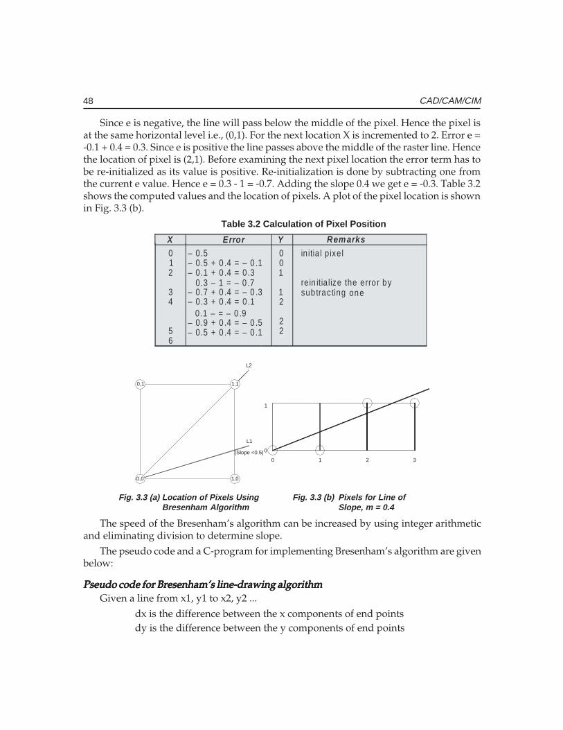
48 CAD/CAM/CIM
Since e is negative, the line will pass below the middle of the pixel. Hence the pixel isat the same horizontal level i.e., (0,1). For the next location X is incremented to 2. Error e =-0.1 + 0.4 = 0.3. Since e is positive the line passes above the middle of the raster line. Hencethe location of pixel is (2,1). Before examining the next pixel location the error term has tobe re-initialized as its value is positive. Re-initialization is done by subtracting one fromthe current e value. Hence e = 0.3 - 1 = -0.7. Adding the slope 0.4 we get e = -0.3. Table 3.2shows the computed values and the location of pixels. A plot of the pixel location is shownin Fig. 3.3 (b).
0,0
0,1 1,1
1,0
L2
L1
(Slope <0.5)0 1 2 3
0
1
Fig. 3.3 (a) Location of Pixels Using Fig. 3.3 (b) Pixels for Line ofBresenham Algorithm Slope, m = 0.4
The speed of the Bresenham’s algorithm can be increased by using integer arithmeticand eliminating division to determine slope.
The pseudo code and a C-program for implementing Bresenham’s algorithm are givenbelow:
Pseudo code for Bresenham’s line-drawing algorithmPseudo code for Bresenham’s line-drawing algorithmPseudo code for Bresenham’s line-drawing algorithmPseudo code for Bresenham’s line-drawing algorithmPseudo code for Bresenham’s line-drawing algorithmGiven a line from x1, y1 to x2, y2 ...
dx is the difference between the x components of end pointsdy is the difference between the y components of end points
Table 3.2 Calculation of Pixel Position X Error Y Remarks 0 1 2
3 4
5 6
0 0 1
1 2
2 2
in itia l p ixel re in itia lize the erro r by
one sub tracting
– 0.5– 0.5 + 0 .4 = – 0 .1– 0.1 + 0 .4 = 0 .3
0.3 – 1 = – 0 .7– 0.7 + 0 .4 = – 0 .3– 0.3 + 0 .4 = 0 .1
0.1 – = – 0 .9– 0.9 + 0 .4 = – 0 .5– 0.5 + 0 .4 = – 0 .1
Ch
ap
ter
3C
ha
pte
r 3
Ch
ap
ter
3C
ha
pte
r 3
Ch
ap
ter
3
49Principles of Computer Graphics
ix is the absolute value of dxiy is the absolute value of dyinc is the larger of dx, dyplotx is x1ploty is y1 (the beginning of line)x starts at 0y starts at 0plot a pixel at plotx, ploty
increment x using ixincrement y using iyplot is falseif x is greater than inc
plot is truedecrement x using incincrement plotx if dx is positivedecrement plotx id dx is negative
if y is greater than incplot is truedecrement y using incincrement ploty if dy is positivedecrement ploty if dy is negativeif plot is true, plot a pixel at plotx, plotyincrement i.
Program in Turbo-C to draw a lineProgram in Turbo-C to draw a lineProgram in Turbo-C to draw a lineProgram in Turbo-C to draw a lineProgram in Turbo-C to draw a line# include <stdio. h># include <graphics. h># include <stdlb. h>void draw line (int x1, int y1, int x2, int y2),void main (void){
draw line (100, 100, 50, 50) ;}void draw line (int x1, int y1, int x2 m int y2){
int dx, dy, inc, ix, iy, x, y, plot, plotx, ploty, i ;
50 CAD/CAM/CIM
int gd, gm ;gd = DETECT ;initgraph (&gd, &gm, “ “) ;dx = x1 – x2 ;dy = y1 – y2 ;ix = abs (dx) ;iy = abs (dy) ;inc = max (ix, iy) ;x = y = 0 ;plot x = x1 ;plot y = y1 ;for (i = 0 ; i <inc ; i ++)
{x + = ix ;y + iy ;plot = 0if (x > inc)
{plot = 1 ;x – = inc ;if (dx < 0)plot x – = 1 ;
elseplotx + = 1 ;
}if (y > inc)
{plot = 1 ;y – = inc ;if (dy)ploty – = 1 ;
elseploty + = 1 ;
}
if (plot)
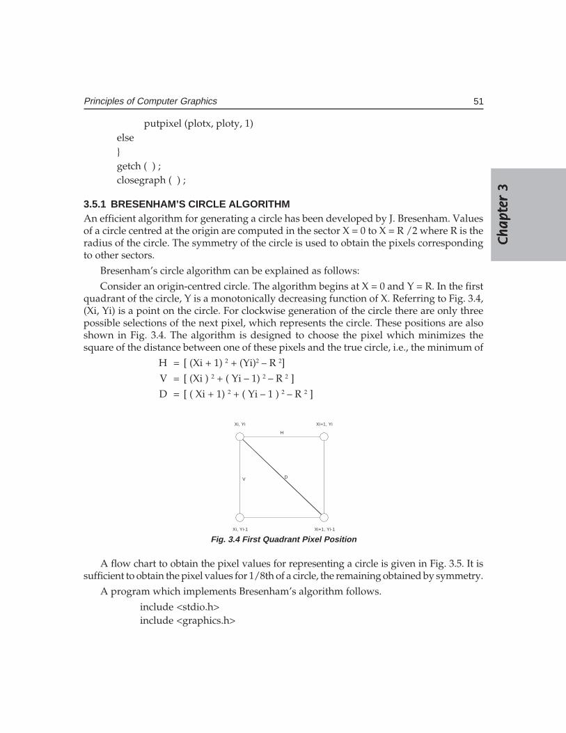
Ch
ap
ter
3C
ha
pte
r 3
Ch
ap
ter
3C
ha
pte
r 3
Ch
ap
ter
3
51Principles of Computer Graphics
putpixel (plotx, ploty, 1)else}getch ( ) ;closegraph ( ) ;
3.5.1 BRESENHAM’S CIRCLE ALGORITHMAn efficient algorithm for generating a circle has been developed by J. Bresenham. Valuesof a circle centred at the origin are computed in the sector X = 0 to X = R /2 where R is theradius of the circle. The symmetry of the circle is used to obtain the pixels correspondingto other sectors.
Bresenham’s circle algorithm can be explained as follows:
Consider an origin-centred circle. The algorithm begins at X = 0 and Y = R. In the firstquadrant of the circle, Y is a monotonically decreasing function of X. Referring to Fig. 3.4,(Xi, Yi) is a point on the circle. For clockwise generation of the circle there are only threepossible selections of the next pixel, which represents the circle. These positions are alsoshown in Fig. 3.4. The algorithm is designed to choose the pixel which minimizes thesquare of the distance between one of these pixels and the true circle, i.e., the minimum of
H = [ (Xi + 1) 2 + (Yi)2 – R 2]
V = [ (Xi ) 2 + ( Yi – 1) 2 – R 2 ]
D = [ ( Xi + 1) 2 + ( Yi – 1 ) 2 – R 2 ]
Xi, Yi-1 Xi+1, Yi-1
Xi, Yi Xi+1, Yi
H
DV
Fig. 3.4 First Quadrant Pixel Position
A flow chart to obtain the pixel values for representing a circle is given in Fig. 3.5. It issufficient to obtain the pixel values for 1/8th of a circle, the remaining obtained by symmetry.
A program which implements Bresenham’s algorithm follows.
include <stdio.h>include <graphics.h>
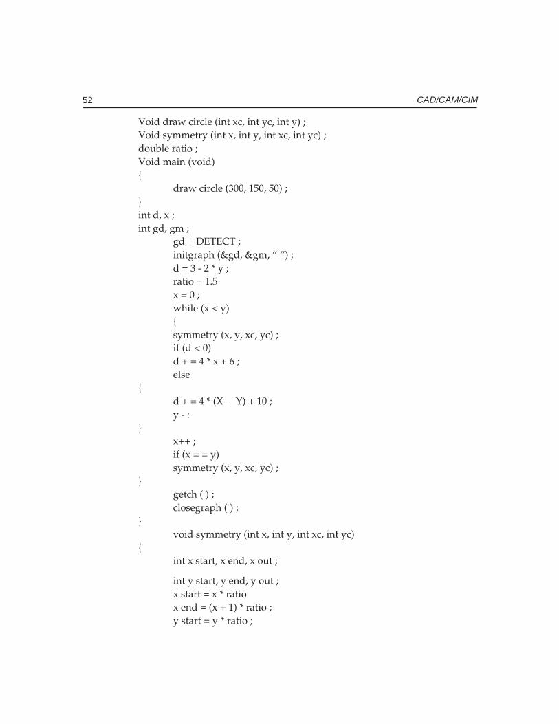
52 CAD/CAM/CIM
Void draw circle (int xc, int yc, int y) ;Void symmetry (int x, int y, int xc, int yc) ;double ratio ;Void main (void){
draw circle (300, 150, 50) ;}int d, x ;int gd, gm ;
gd = DETECT ;initgraph (&gd, &gm, “ “) ;d = 3 - 2 * y ;ratio = 1.5x = 0 ;while (x < y){symmetry (x, y, xc, yc) ;if (d < 0)d + = 4 * x + 6 ;else
{d + = 4 * (X – Y) + 10 ;y - :
}x++ ;if (x = = y)symmetry (x, y, xc, yc) ;
}getch ( ) ;closegraph ( ) ;
}void symmetry (int x, int y, int xc, int yc)
{int x start, x end, x out ;
int y start, y end, y out ;x start = x * ratiox end = (x + 1) * ratio ;y start = y * ratio ;
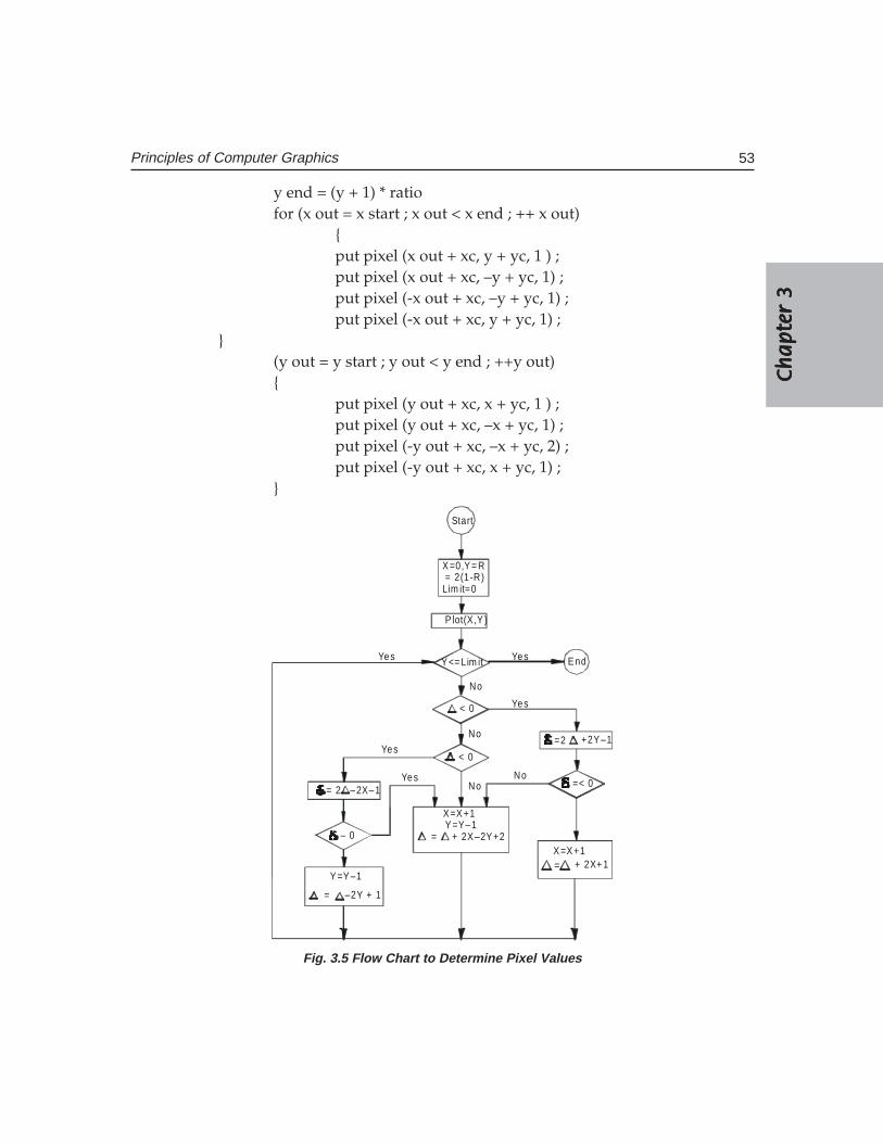
Ch
ap
ter
3C
ha
pte
r 3
Ch
ap
ter
3C
ha
pte
r 3
Ch
ap
ter
3
53Principles of Computer Graphics
y end = (y + 1) * ratiofor (x out = x start ; x out < x end ; ++ x out)
{put pixel (x out + xc, y + yc, 1 ) ;put pixel (x out + xc, –y + yc, 1) ;put pixel (-x out + xc, –y + yc, 1) ;put pixel (-x out + xc, y + yc, 1) ;
}(y out = y start ; y out < y end ; ++y out){
put pixel (y out + xc, x + yc, 1 ) ;put pixel (y out + xc, –x + yc, 1) ;put pixel (-y out + xc, –x + yc, 2) ;put pixel (-y out + xc, x + yc, 1) ;
}
Start
X =0,Y = R = 2(1 -R)Lim it=0
P lot(X,Y )
Y <= Lim it E nd
No
X =X +1Y =Y 1–
X =X +1= + 2X 2Y +2–
= + 2X+ 1Y =Y 1–
= –2Y + 1
< 0
< 0
– 0
= 2 –2X 1–
No
No
=2 +2Y 1–
=< 0
Yes
Yes
Yes
Yes
NoYes
Fig. 3.5 Flow Chart to Determine Pixel Values
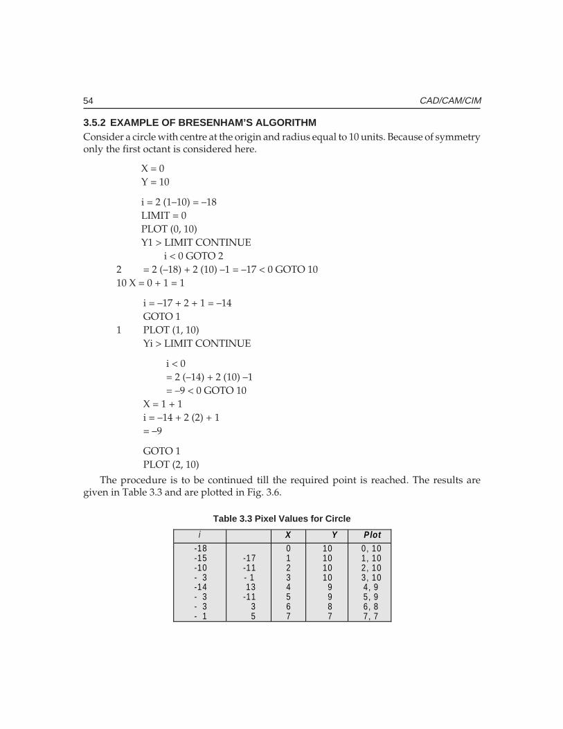
54 CAD/CAM/CIM
3.5.2 EXAMPLE OF BRESENHAM’S ALGORITHMConsider a circle with centre at the origin and radius equal to 10 units. Because of symmetryonly the first octant is considered here.
X = 0Y = 10
i = 2 (1–10) = –18LIMIT = 0PLOT (0, 10)Y1 > LIMIT CONTINUE
i < 0 GOTO 22 = 2 (–18) + 2 (10) –1 = –17 < 0 GOTO 1010 X = 0 + 1 = 1
i = –17 + 2 + 1 = –14GOTO 1
1 PLOT (1, 10)Yi > LIMIT CONTINUE
i < 0= 2 (–14) + 2 (10) –1= –9 < 0 GOTO 10
X = 1 + 1i = –14 + 2 (2) + 1= –9
GOTO 1PLOT (2, 10)
The procedure is to be continued till the required point is reached. The results aregiven in Table 3.3 and are plotted in Fig. 3.6.
Table 3.3 Pixel Values for Circle
i X Y Plot -18 -15 -10 - 3 -14 - 3 - 3 - 1
-17 -11 - 1 13 -11 3 5
0 1 2 3 4 5 6 7
10 10 10 10 9 9 8 7
0, 10 1, 10 2, 10 3, 10 4, 9 5, 9 6, 8 7, 7
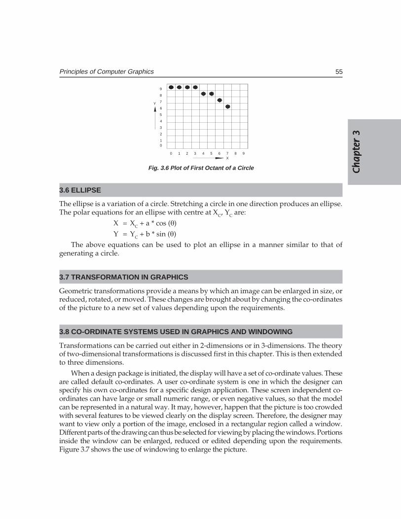
Ch
ap
ter
3C
ha
pte
r 3
Ch
ap
ter
3C
ha
pte
r 3
Ch
ap
ter
3
55Principles of Computer Graphics
0 1 2 3 4 5 6 7 8 9
01
2
3
4
5
6
7
8
9
Y
X
Fig. 3.6 Plot of First Octant of a Circle
3.6 ELLIPSE
The ellipse is a variation of a circle. Stretching a circle in one direction produces an ellipse.The polar equations for an ellipse with centre at XC, YC are:
X = XC + a * cos (θ)Y = YC + b * sin (θ)
The above equations can be used to plot an ellipse in a manner similar to that ofgenerating a circle.
3.7 TRANSFORMATION IN GRAPHICS
Geometric transformations provide a means by which an image can be enlarged in size, orreduced, rotated, or moved. These changes are brought about by changing the co-ordinatesof the picture to a new set of values depending upon the requirements.
3.8 CO-ORDINATE SYSTEMS USED IN GRAPHICS AND WINDOWING
Transformations can be carried out either in 2-dimensions or in 3-dimensions. The theoryof two-dimensional transformations is discussed first in this chapter. This is then extendedto three dimensions.
When a design package is initiated, the display will have a set of co-ordinate values. Theseare called default co-ordinates. A user co-ordinate system is one in which the designer canspecify his own co-ordinates for a specific design application. These screen independent co-ordinates can have large or small numeric range, or even negative values, so that the modelcan be represented in a natural way. It may, however, happen that the picture is too crowdedwith several features to be viewed clearly on the display screen. Therefore, the designer maywant to view only a portion of the image, enclosed in a rectangular region called a window.Different parts of the drawing can thus be selected for viewing by placing the windows. Portionsinside the window can be enlarged, reduced or edited depending upon the requirements.Figure 3.7 shows the use of windowing to enlarge the picture.
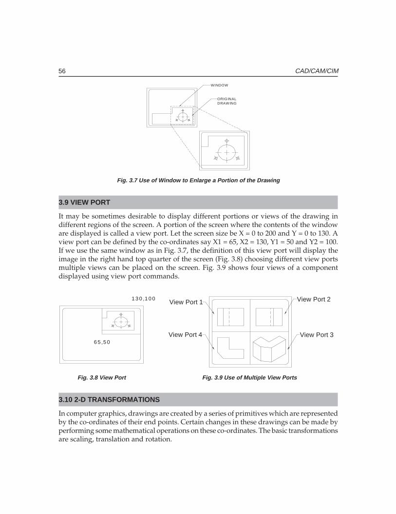
56 CAD/CAM/CIM
ORIGINALDRAW ING
WINDOW
Fig. 3.7 Use of Window to Enlarge a Portion of the Drawing
3.9 VIEW PORT
It may be sometimes desirable to display different portions or views of the drawing indifferent regions of the screen. A portion of the screen where the contents of the windoware displayed is called a view port. Let the screen size be X = 0 to 200 and Y = 0 to 130. Aview port can be defined by the co-ordinates say X1 = 65, X2 = 130, Y1 = 50 and Y2 = 100.If we use the same window as in Fig. 3.7, the definition of this view port will display theimage in the right hand top quarter of the screen (Fig. 3.8) choosing different view portsmultiple views can be placed on the screen. Fig. 3.9 shows four views of a componentdisplayed using view port commands.
6 5 ,5 0
1 3 0 ,1 0 0View Port 1 View Port 2
View Port 3View Port 4
Fig. 3.8 View Port Fig. 3.9 Use of Multiple View Ports
3.10 2-D TRANSFORMATIONS
In computer graphics, drawings are created by a series of primitives which are representedby the co-ordinates of their end points. Certain changes in these drawings can be made byperforming some mathematical operations on these co-ordinates. The basic transformationsare scaling, translation and rotation.
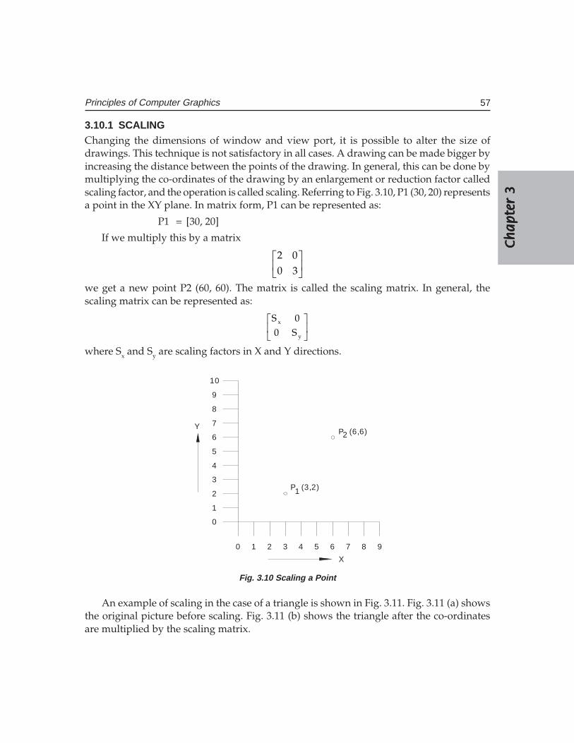
Ch
ap
ter
3C
ha
pte
r 3
Ch
ap
ter
3C
ha
pte
r 3
Ch
ap
ter
3
57Principles of Computer Graphics
3.10.1 SCALINGChanging the dimensions of window and view port, it is possible to alter the size ofdrawings. This technique is not satisfactory in all cases. A drawing can be made bigger byincreasing the distance between the points of the drawing. In general, this can be done bymultiplying the co-ordinates of the drawing by an enlargement or reduction factor calledscaling factor, and the operation is called scaling. Referring to Fig. 3.10, P1 (30, 20) representsa point in the XY plane. In matrix form, P1 can be represented as:
P1 = [30, 20]
If we multiply this by a matrix
2 00 3
we get a new point P2 (60, 60). The matrix is called the scaling matrix. In general, thescaling matrix can be represented as:
x
y
S 00 S
where Sx and Sy are scaling factors in X and Y directions.
0 1 2 3 4 5 6 7 8 9
0
1
2
3
4
5
6
7
8
9
10
P (3,2)
P (6,6)
1
2
X
Y
Fig. 3.10 Scaling a Point
An example of scaling in the case of a triangle is shown in Fig. 3.11. Fig. 3.11 (a) showsthe original picture before scaling. Fig. 3.11 (b) shows the triangle after the co-ordinatesare multiplied by the scaling matrix.
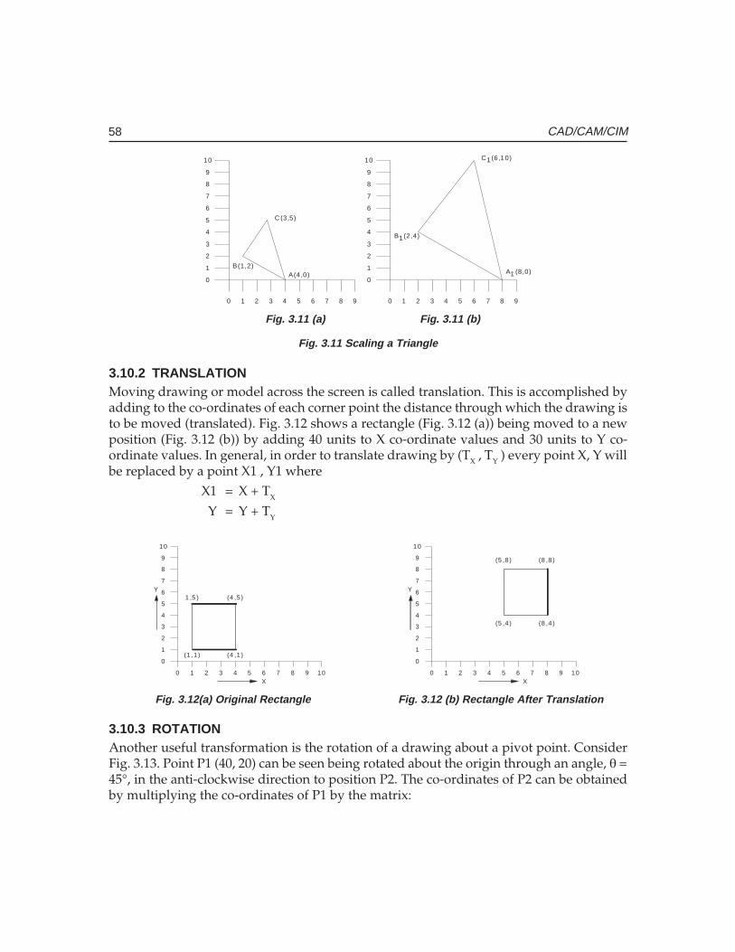
58 CAD/CAM/CIM
0 1 2 3 4 5 6 7 8 9
0
1
2
3
4
5
6
7
8
9
10
0 1 2 3
1
0
3
2
74 5 6 8 9
6
4
5
8
7
9
10
A(4,0)B(1,2)
C (3,5)
A (8,0)
B (2,4)
C (6,1 0)
1
1
1
Fig. 3.11 (a) Fig. 3.11 (b)
Fig. 3.11 Scaling a Triangle
3.10.2 TRANSLATIONMoving drawing or model across the screen is called translation. This is accomplished byadding to the co-ordinates of each corner point the distance through which the drawing isto be moved (translated). Fig. 3.12 shows a rectangle (Fig. 3.12 (a)) being moved to a newposition (Fig. 3.12 (b)) by adding 40 units to X co-ordinate values and 30 units to Y co-ordinate values. In general, in order to translate drawing by (TX , TY ) every point X, Y willbe replaced by a point X1 , Y1 where
X1 = X + TX
Y = Y + TY
0 1 2 3 4 5 6 7 8 9
0
1
2
3
4
5
6
7
8
9
10
10
(1 ,1 ) (4 ,1 )
1 ,5 ) (4 ,5 )
X
Y
0 1 2 3
1
0
3
2
74 5 6 8 9
6
4
5
8
7
9
10
10
(5 ,4 ) (8 ,4 )
(8 ,8 )(5 ,8 )
Y
X
Fig. 3.12(a) Original Rectangle Fig. 3.12 (b) Rectangle After Translation
3.10.3 ROTATIONAnother useful transformation is the rotation of a drawing about a pivot point. ConsiderFig. 3.13. Point P1 (40, 20) can be seen being rotated about the origin through an angle, θ =45°, in the anti-clockwise direction to position P2. The co-ordinates of P2 can be obtainedby multiplying the co-ordinates of P1 by the matrix:
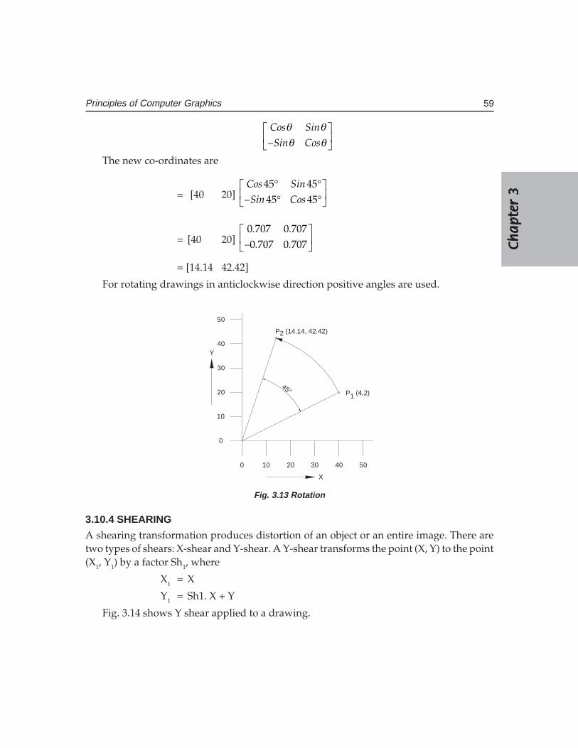
Ch
ap
ter
3C
ha
pte
r 3
Ch
ap
ter
3C
ha
pte
r 3
Ch
ap
ter
3
59Principles of Computer Graphics
Cos Sin
–Sin Cos
θ θθ θ
The new co-ordinates are
= [40 20] Cos Sin
–Sin Cos
° ° ° °
45 4545 45
= [40 20] . .
– . .
0 707 0 7070 707 0 707
= [14.14 42.42]
For rotating drawings in anticlockwise direction positive angles are used.
45°
0 10 20 30 40 50
0
10
20
30
40
50
X
Y
P (4,2)1
P (14.14, 42.42)2
Fig. 3.13 Rotation
3.10.4 SHEARING
A shearing transformation produces distortion of an object or an entire image. There aretwo types of shears: X-shear and Y-shear. A Y-shear transforms the point (X, Y) to the point(X1, Y1) by a factor Sh1, where
X1 = X
Y1 = Sh1. X + Y
Fig. 3.14 shows Y shear applied to a drawing.
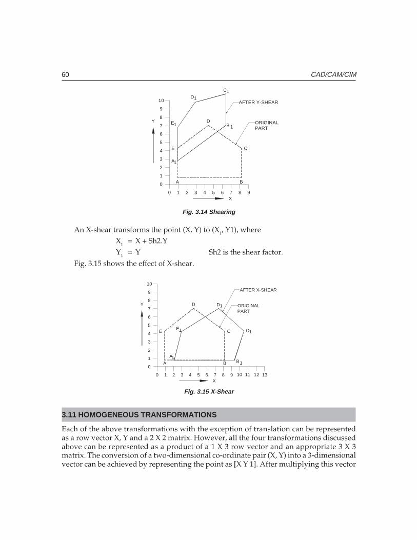
60 CAD/CAM/CIM
0 1 2 3 4 5 6 7 8 9
0
1
2
3
4
5
6
7
8
9
10
A B
C
D
E
A
B
CD
E
1
1
1
1
1
X
Y ORIGINALPART
AFTER Y-SHEAR
Fig. 3.14 Shearing
An X-shear transforms the point (X, Y) to (X1, Y1), whereX1 = X + Sh2.YY1 = Y Sh2 is the shear factor.
Fig. 3.15 shows the effect of X-shear.
0 1 2 3 4 5 6 7 8 9
0
1
2
3
4
5
6
7
8
9
10
A B
C
D
E
AB
C
D
E
11
1
1
1
X
Y ORIGINALPART
10 11 12 13
AFTER X-SHEAR
Fig. 3.15 X-Shear
3.11 HOMOGENEOUS TRANSFORMATIONS
Each of the above transformations with the exception of translation can be representedas a row vector X, Y and a 2 X 2 matrix. However, all the four transformations discussedabove can be represented as a product of a 1 X 3 row vector and an appropriate 3 X 3matrix. The conversion of a two-dimensional co-ordinate pair (X, Y) into a 3-dimensionalvector can be achieved by representing the point as [X Y 1]. After multiplying this vector
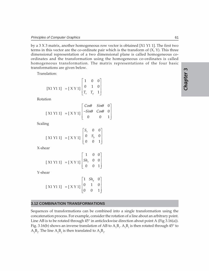
Ch
ap
ter
3C
ha
pte
r 3
Ch
ap
ter
3C
ha
pte
r 3
Ch
ap
ter
3
61Principles of Computer Graphics
by a 3 X 3 matrix, another homogeneous row vector is obtained [X1 Y1 1]. The first twoterms in this vector are the co-ordinate pair which is the transform of (X, Y). This threedimensional representation of a two dimensional plane is called homogeneous co-ordinates and the transformation using the homogeneous co-ordinates is calledhomogeneous transformation. The matrix representations of the four basictransformations are given below.
Translation:
[X1 Y1 1] = [ X Y 1] x yT T
1 0 00 1 0
1
Rotation
[ X1 Y1 1] = [ X Y 1]
Cos SinSin Cos
−
00
0 0 1
θ θθ θ
Scaling
[ X1 Y1 1] = [ X Y 1]
x
y
SS
0 00 00 0 1
X-shear
[ X1 Y1 1] = [ X Y 1] xSh
1 0 00 0
0 0 1
Y-shear
[ X1 Y1 1] = [ X Y 1]
ySh
1 00 1 00 0 1
3.12 COMBINATION TRANSFORMATIONS
Sequences of transformations can be combined into a single transformation using theconcatenation process. For example, consider the rotation of a line about an arbitrary point.Line AB is to be rotated through 45° in anticlockwise direction about point A (Fig 3.16(a)).Fig. 3.16(b) shows an inverse translation of AB to A1B1. A1B1 is then rotated through 45° toA2B2. The line A2B2 is then translated to A3B3.
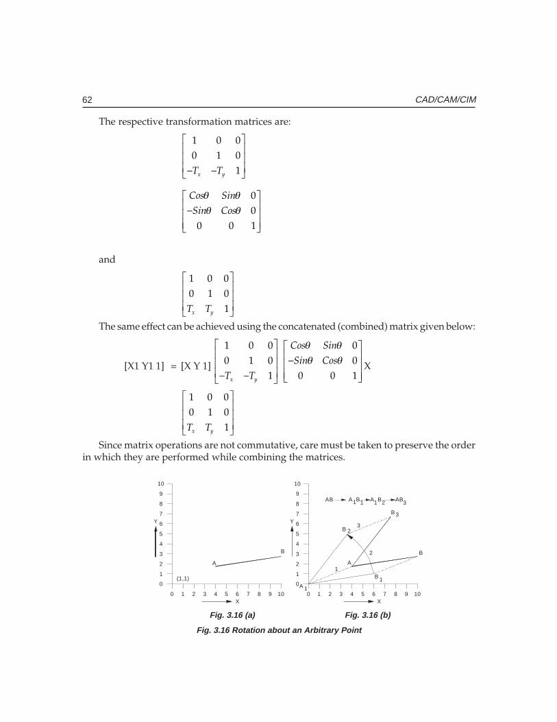
62 CAD/CAM/CIM
The respective transformation matrices are:
x yT T
− −
1 0 00 1 0
1
Cos Sin
Sin Cos
θ θθ θ
−
00
0 0 1
and
x yT T
1 0 00 1 0
1
The same effect can be achieved using the concatenated (combined) matrix given below:
[X1 Y1 1] = [X Y 1] x yT T
− −
1 0 00 1 0
1�
Cos Sin
Sin Cos
θ θθ θ
−
00
0 0 1X
x yT T
1 0 00 1 0
1
Since matrix operations are not commutative, care must be taken to preserve the orderin which they are performed while combining the matrices.
0 1 2 3 4 5 6 7 8 9
0
1
2
3
4
5
6
7
8
9
10
0 1 2 3
1
0
3
2
74 5 6 8 9
6
4
5
8
7
9
10
10 10
(1,1)
X
Y Y
X
1
2
3
A
B
A 1
B 1
B 2
A
B 3
B
AB A B A B AB 1 1 1 2 3
Fig. 3.16 (a) Fig. 3.16 (b)
Fig. 3.16 Rotation about an Arbitrary Point
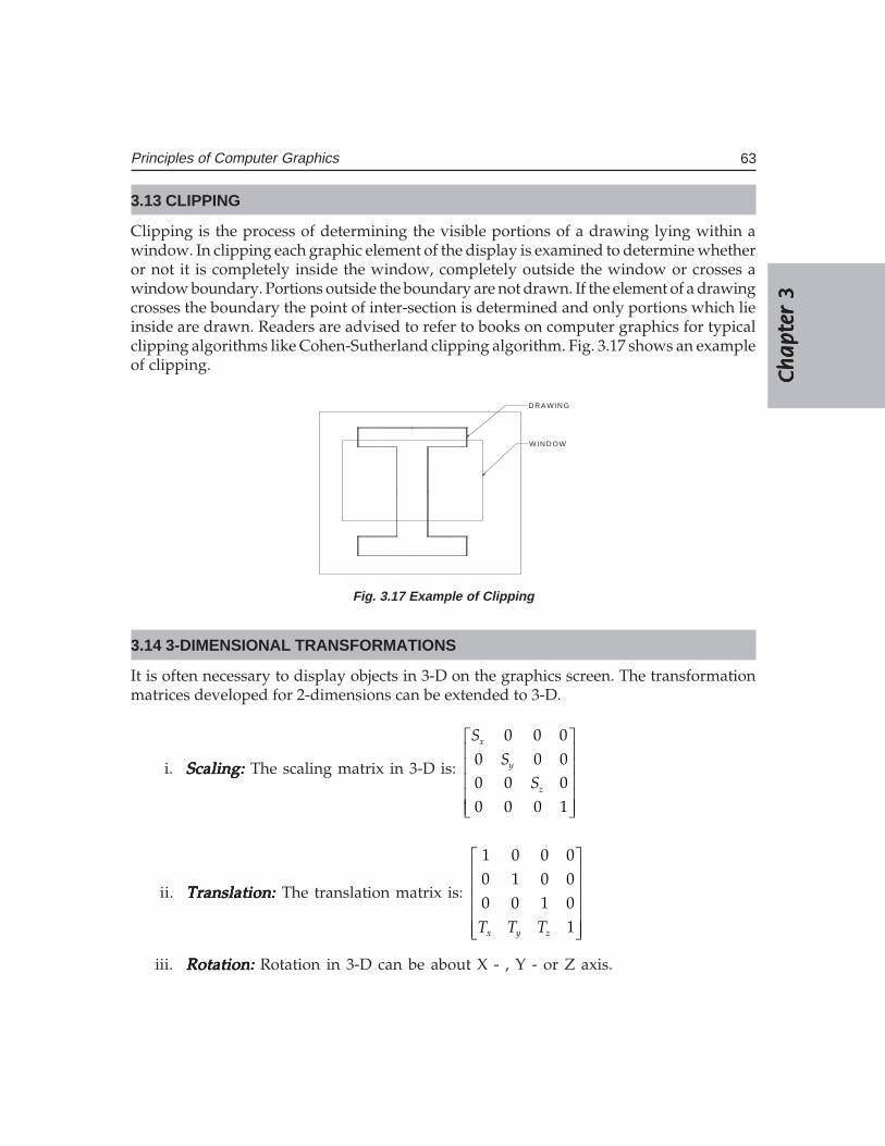
Ch
ap
ter
3C
ha
pte
r 3
Ch
ap
ter
3C
ha
pte
r 3
Ch
ap
ter
3
63Principles of Computer Graphics
3.13 CLIPPING
Clipping is the process of determining the visible portions of a drawing lying within awindow. In clipping each graphic element of the display is examined to determine whetheror not it is completely inside the window, completely outside the window or crosses awindow boundary. Portions outside the boundary are not drawn. If the element of a drawingcrosses the boundary the point of inter-section is determined and only portions which lieinside are drawn. Readers are advised to refer to books on computer graphics for typicalclipping algorithms like Cohen-Sutherland clipping algorithm. Fig. 3.17 shows an exampleof clipping.
W INDOW
DRA W ING
Fig. 3.17 Example of Clipping
3.14 3-DIMENSIONAL TRANSFORMATIONS
It is often necessary to display objects in 3-D on the graphics screen. The transformationmatrices developed for 2-dimensions can be extended to 3-D.
i. Scaling: Scaling: Scaling: Scaling: Scaling: The scaling matrix in 3-D is:
x
y
z
S
SS
0 0 00 0 00 0 00 0 0 1
ii. Translation:Translation:Translation:Translation:Translation: The translation matrix is:
x y zT T T
1 0 0 00 1 0 00 0 1 0
1
iii. Rotation:Rotation:Rotation:Rotation:Rotation: Rotation in 3-D can be about X - , Y - or Z axis.
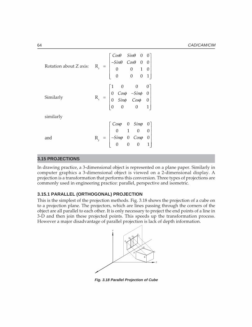
64 CAD/CAM/CIM
Rotation about Z axis: Rz =
Cos Sin
Sin Cos
θ θθ θ
−
0 00 0
0 0 1 00 0 0 1
Similarly Rx =Cos SinSin Cos
φ φφ φ
−
1 0 0 00 00 00 0 0 1
similarly
and Ry =
Cos Sin
Sin Cos
ϕ ϕ
ϕ ϕ
−
0 00 1 0 0
0 00 0 0 1
3.15 PROJECTIONS
In drawing practice, a 3-dimensional object is represented on a plane paper. Similarly incomputer graphics a 3-dimensional object is viewed on a 2-dimensional display. Aprojection is a transformation that performs this conversion. Three types of projections arecommonly used in engineering practice: parallel, perspective and isometric.
3.15.1 PARALLEL (ORTHOGONAL) PROJECTIONThis is the simplest of the projection methods. Fig. 3.18 shows the projection of a cube onto a projection plane. The projectors, which are lines passing through the corners of theobject are all parallel to each other. It is only necessary to project the end points of a line in3-D and then join these projected points. This speeds up the transformation process.However a major disadvantage of parallel projection is lack of depth information.
A
B
C
D
A
BD
C
1
11
1
Y
Z
Fig. 3.18 Parallel Projection of Cube
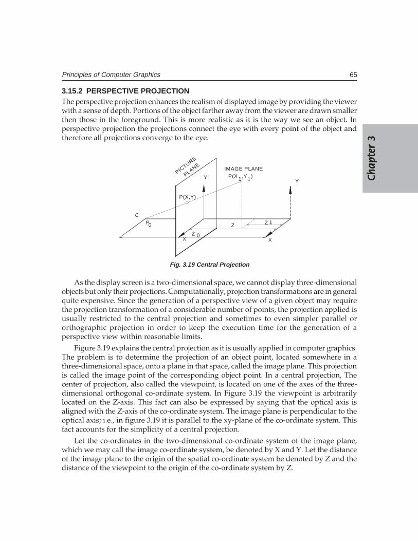
Ch
ap
ter
3C
ha
pte
r 3
Ch
ap
ter
3C
ha
pte
r 3
Ch
ap
ter
3
65Principles of Computer Graphics
3.15.2 PERSPECTIVE PROJECTIONThe perspective projection enhances the realism of displayed image by providing the viewerwith a sense of depth. Portions of the object farther away from the viewer are drawn smallerthen those in the foreground. This is more realistic as it is the way we see an object. Inperspective projection the projections connect the eye with every point of the object andtherefore all projections converge to the eye.
CP0
P(X,Y)
Y
IMAGE PLANEP(X 1,Y
1)
Y
XX
PICTURE
PLANE
Z 0
Z Z 1
Fig. 3.19 Central Projection
As the display screen is a two-dimensional space, we cannot display three-dimensionalobjects but only their projections. Computationally, projection transformations are in generalquite expensive. Since the generation of a perspective view of a given object may requirethe projection transformation of a considerable number of points, the projection applied isusually restricted to the central projection and sometimes to even simpler parallel ororthographic projection in order to keep the execution time for the generation of aperspective view within reasonable limits.
Figure 3.19 explains the central projection as it is usually applied in computer graphics.The problem is to determine the projection of an object point, located somewhere in athree-dimensional space, onto a plane in that space, called the image plane. This projectionis called the image point of the corresponding object point. In a central projection, Thecenter of projection, also called the viewpoint, is located on one of the axes of the three-dimensional orthogonal co-ordinate system. In Figure 3.19 the viewpoint is arbitrarilylocated on the Z-axis. This fact can also be expressed by saying that the optical axis isaligned with the Z-axis of the co-ordinate system. The image plane is perpendicular to theoptical axis; i.e., in figure 3.19 it is parallel to the xy-plane of the co-ordinate system. Thisfact accounts for the simplicity of a central projection.
Let the co-ordinates in the two-dimensional co-ordinate system of the image plane,which we may call the image co-ordinate system, be denoted by X and Y. Let the distanceof the image plane to the origin of the spatial co-ordinate system be denoted by Z and thedistance of the viewpoint to the origin of the co-ordinate system by Z.

66 CAD/CAM/CIM
Then it follows from an elementary theorem of geometry that
X =Z Z
XZ Z
−−
01
0 1
Y =Z Z
YZ Z
−−
01
0 1
A further simplification can be obtained by setting Z1 = 0. i.e., by moving into the XYplane of the spatial co-ordinate system. Then we have
X =Z Z
XZ−0
10
Y =Z Z
YZ−0
10
For even further simplification, we may move the viewpoint C toward infinity. With Z0→ ∞, and we have the trivial solution
X = X1 and Y = Y1
This projection is called orthographic. The orthographic projection is a special form ofthe parallel projection by which parallel lines of the three-dimensional object aretransformed into parallel lines of its image.
3.15.3 ISOMETRIC PROJECTIONIn isometric projection the three orthogonal edges of an object are inclined equally to theprojection plane. Because of the relative ease of projection and the ability to give 3-Dperception, isometric projection is widely used in computer aided design.
In computer aided design the co-ordinates of the drawing are available in their naturalco-ordinate system. These are transformed suitably to enable the viewer different views orrotate the object in such away that all the faces of the object are made visible continuously.There are several uses for this technique in product design. Hence good design packagesincorporate several viewing transformation techniques. The viewing parameters dependupon the system graphics standard followed in developing the graphics package. Thealgorithms for these viewing transformations are available in literature.
3.16 SCAN CONVERSION
In order to display rasterized image using video technology it is necessary to organizethe picture into the precise pattern required by the video display. This is called scanconversion. The display information must be organized and presented in the scan lineorder i.e., from top to bottom and from left to right. There are several techniques of scanconversion.
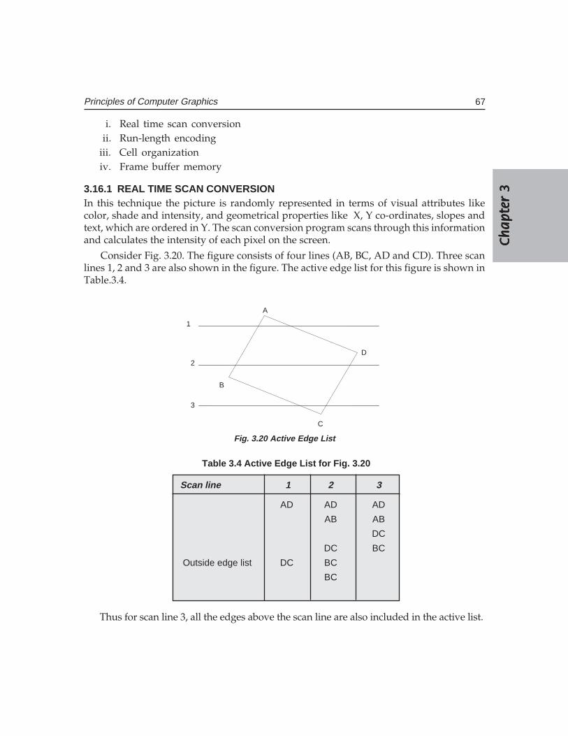
Ch
ap
ter
3C
ha
pte
r 3
Ch
ap
ter
3C
ha
pte
r 3
Ch
ap
ter
3
67Principles of Computer Graphics
i. Real time scan conversionii. Run-length encoding
iii. Cell organizationiv. Frame buffer memory
3.16.1 REAL TIME SCAN CONVERSIONIn this technique the picture is randomly represented in terms of visual attributes likecolor, shade and intensity, and geometrical properties like X, Y co-ordinates, slopes andtext, which are ordered in Y. The scan conversion program scans through this informationand calculates the intensity of each pixel on the screen.
Consider Fig. 3.20. The figure consists of four lines (AB, BC, AD and CD). Three scanlines 1, 2 and 3 are also shown in the figure. The active edge list for this figure is shown inTable.3.4.
A
B
C
D
1
2
3
Fig. 3.20 Active Edge List
Table 3.4 Active Edge List for Fig. 3.20
Scan line 1 2 3
AD AD AD
AB AB
DC
DC BC
Outside edge list DC BC
BC
Thus for scan line 3, all the edges above the scan line are also included in the active list.
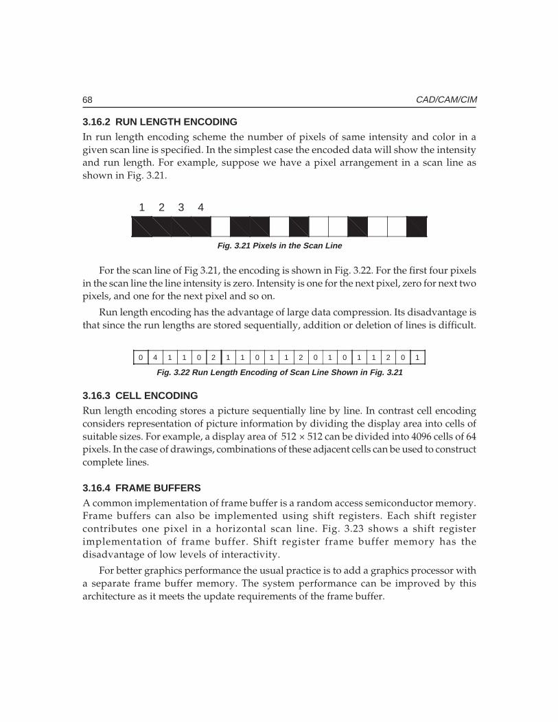
68 CAD/CAM/CIM
3.16.2 RUN LENGTH ENCODINGIn run length encoding scheme the number of pixels of same intensity and color in agiven scan line is specified. In the simplest case the encoded data will show the intensityand run length. For example, suppose we have a pixel arrangement in a scan line asshown in Fig. 3.21.
1 2 3 4
Fig. 3.21 Pixels in the Scan Line
For the scan line of Fig 3.21, the encoding is shown in Fig. 3.22. For the first four pixelsin the scan line the line intensity is zero. Intensity is one for the next pixel, zero for next twopixels, and one for the next pixel and so on.
Run length encoding has the advantage of large data compression. Its disadvantage isthat since the run lengths are stored sequentially, addition or deletion of lines is difficult.
0 4 1 1 0 2 1 1 0 1 1 2 0 1 1 2 0 10 1
Fig. 3.22 Run Length Encoding of Scan Line Shown in Fig. 3.21
3.16.3 CELL ENCODINGRun length encoding stores a picture sequentially line by line. In contrast cell encodingconsiders representation of picture information by dividing the display area into cells ofsuitable sizes. For example, a display area of 512 × 512 can be divided into 4096 cells of 64pixels. In the case of drawings, combinations of these adjacent cells can be used to constructcomplete lines.
3.16.4 FRAME BUFFERSA common implementation of frame buffer is a random access semiconductor memory.Frame buffers can also be implemented using shift registers. Each shift registercontributes one pixel in a horizontal scan line. Fig. 3.23 shows a shift registerimplementation of frame buffer. Shift register frame buffer memory has thedisadvantage of low levels of interactivity.
For better graphics performance the usual practice is to add a graphics processor witha separate frame buffer memory. The system performance can be improved by thisarchitecture as it meets the update requirements of the frame buffer.
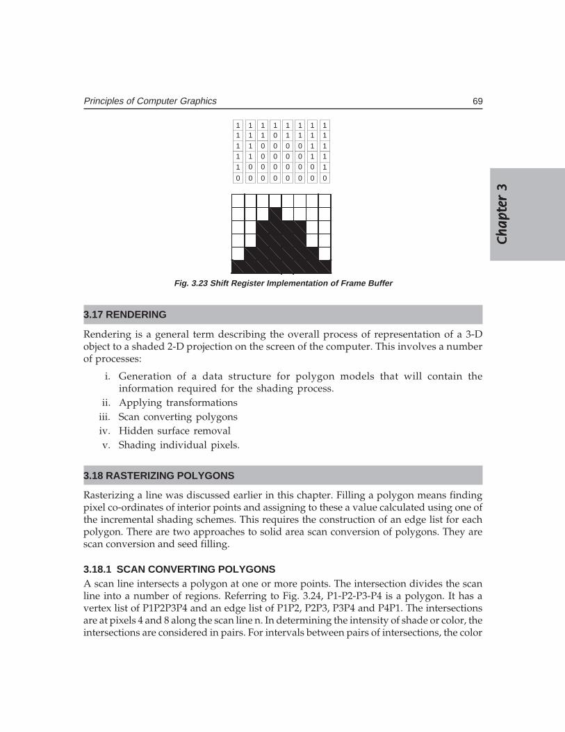
Ch
ap
ter
3C
ha
pte
r 3
Ch
ap
ter
3C
ha
pte
r 3
Ch
ap
ter
3
69Principles of Computer Graphics
1 1 1 1 1 1 1 11 1 1 0 1 1 1 1
1 1 0 0 0 0 1 11 1 0 0 0 0 1 1
1 0 0 0 0 0 0 1
0 0 0 0 0 0 0 0
Fig. 3.23 Shift Register Implementation of Frame Buffer
3.17 RENDERING
Rendering is a general term describing the overall process of representation of a 3-Dobject to a shaded 2-D projection on the screen of the computer. This involves a numberof processes:
i. Generation of a data structure for polygon models that will contain theinformation required for the shading process.
ii. Applying transformationsiii. Scan converting polygonsiv. Hidden surface removalv. Shading individual pixels.
3.18 RASTERIZING POLYGONS
Rasterizing a line was discussed earlier in this chapter. Filling a polygon means findingpixel co-ordinates of interior points and assigning to these a value calculated using one ofthe incremental shading schemes. This requires the construction of an edge list for eachpolygon. There are two approaches to solid area scan conversion of polygons. They arescan conversion and seed filling.
3.18.1 SCAN CONVERTING POLYGONSA scan line intersects a polygon at one or more points. The intersection divides the scanline into a number of regions. Referring to Fig. 3.24, P1-P2-P3-P4 is a polygon. It has avertex list of P1P2P3P4 and an edge list of P1P2, P2P3, P3P4 and P4P1. The intersectionsare at pixels 4 and 8 along the scan line n. In determining the intensity of shade or color, theintersections are considered in pairs. For intervals between pairs of intersections, the color
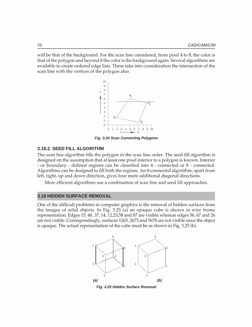
70 CAD/CAM/CIM
will be that of the background. For the scan line considered, from pixel 4 to 8, the color isthat of the polygon and beyond 8 the color is the background again. Several algorithms areavailable to create ordered edge lists. These take into consideration the intersection of thescan line with the vertices of the polygon also.
0 1 2 3 4 5 6 7 8 9
0
1
2
3
4
5
6
7
8
9
10
X
Y
10
P1
P2
P3
P4
Fig. 3.24 Scan Converting Polygons
3.18.2. SEED FILL ALGORITHMThe scan line algorithm fills the polygon in the scan line order. The seed fill algorithm isdesigned on the assumption that at least one pixel interior to a polygon is known. Interior- or boundary - defined regions can be classified into 4 - connected or 8 - connected.Algorithms can be designed to fill both the regions. An 8-connected algorithm, apart fromleft, right, up and down direction, gives four more additional diagonal directions.
More efficient algorithms use a combination of scan line and seed fill approaches.
3.19 HIDDEN SURFACE REMOVAL
One of the difficult problems in computer graphics is the removal of hidden surfaces fromthe images of solid objects. In Fig. 3.25 (a) an opaque cube is shown in wire framerepresentation. Edges 15, 48, 37, 14, 12,23,58 and 87 are visible whereas edges 56, 67 and 26are not visible. Correspondingly, surfaces 1265, 2673 and 5678 are not visible since the objectis opaque. The actual representation of the cube must be as shown in Fig. 3.25 (b).
1
2
3
4
5
6
7
8
3
2
4
1
5
8
7
(a) (b)
Fig. 3.25 Hidden Surface Removal
Ch
ap
ter
3C
ha
pte
r 3
Ch
ap
ter
3C
ha
pte
r 3
Ch
ap
ter
3
71Principles of Computer Graphics
There are a number of algorithms available for removal of hidden lines and hiddensurfaces. Table 3.5 gives a list of algorithms for hidden line removal and hidden surfaceremoval.
Table 3.5 Algorithms for Hidden Line and Hidden Surface
Hidden line removal Hidden surface removal
Floating horizon Blinn-WhittedImage space Catmull subdivisionList priority ClarkObject space Lane CarpenterRay tracing Scan lineRoberts Warnock Image space
List priorityNewell -Newell-SanchaSchumacherObject spaceRay tracingRoberts AlgorithmScan line Z-bufferWarnockWatkinsWeiler Atherton
There are two popular approaches to hidden surface removal. These are scan line basedsystems and Z-buffer based systems. Other important approaches are area subdivisionand depth list schemes.
3.19.1 Z-BUFFER ALGORITHMThis scheme was developed by Catmull using Sutherland’s classification scheme. In thistechnique, pixels interior to a polygon are shaded and their depth is evaluated byinterpolation from Z-values of the polygon vertices after the viewing transformationhas been applied. For every pixel, (X, Y) values are the pixel co-ordinates and Z value isthe viewing space depth. For each interior polygon point a search is carried out todetermine the minimum Z value. This search is conveniently implemented using a Z-buffer that holds for a current point (X, Y) the smallest Z value so far encountered. TheZ-buffer algorithm has the advantage of simplicity. It handles scenes of any complexity.There is also no computation required for depth sort. The storage space required, howeveris large. This could be reduced by pre-processing, so that polygons nearest the viewpointare processed first.
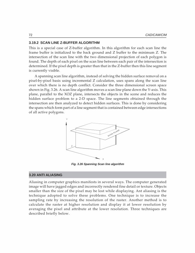
72 CAD/CAM/CIM
3.19.2 SCAN LINE Z-BUFFER ALGORITHMThis is a special case of Z-buffer algorithm. In this algorithm for each scan line theframe buffer is initialized to the back ground and Z buffer to the minimum Z. Theintersection of the scan line with the two dimensional projection of each polygon isfound. The depth of each pixel on the scan line between each pair of the intersection isdetermined. If the pixel depth is greater than that in the Z-buffer then this line segmentis currently visible.
A spanning scan line algorithm, instead of solving the hidden surface removal on apixel-by-pixel basis using incremental Z calculation, uses spans along the scan lineover which there is no depth conflict. Consider the three dimensional screen spaceshown in Fig. 3.26. A scan line algorithm moves a scan line plane down the Y-axis. Thisplane, parallel to the XOZ plane, intersects the objects in the scene and reduces thehidden surface problem to a 2-D space. The line segments obtained through theintersection are then analyzed to detect hidden surfaces. This is done by consideringthe spans which form part of a line segment that is contained between edge intersectionsof all active polygons.
SC AN PLAN E
Y
X
Z
Fig. 3.26 Spanning Scan line algorithm
3.20 ANTI ALIASING
Aliasing in computer graphics manifests in several ways. The computer generatedimage will have jagged edges and incorrectly rendered fine detail or texture. Objectssmaller than the size of the pixel may be lost while displaying. Ant aliasing is thetechnique adopted to solve these problems. One technique is to increase thesampling rate by increasing the resolution of the raster. Another method is tocalculate the raster at higher resolution and display it at lower resolution byaveraging the pixel and attribute at the lower resolution. Three techniques aredescribed briefly below.
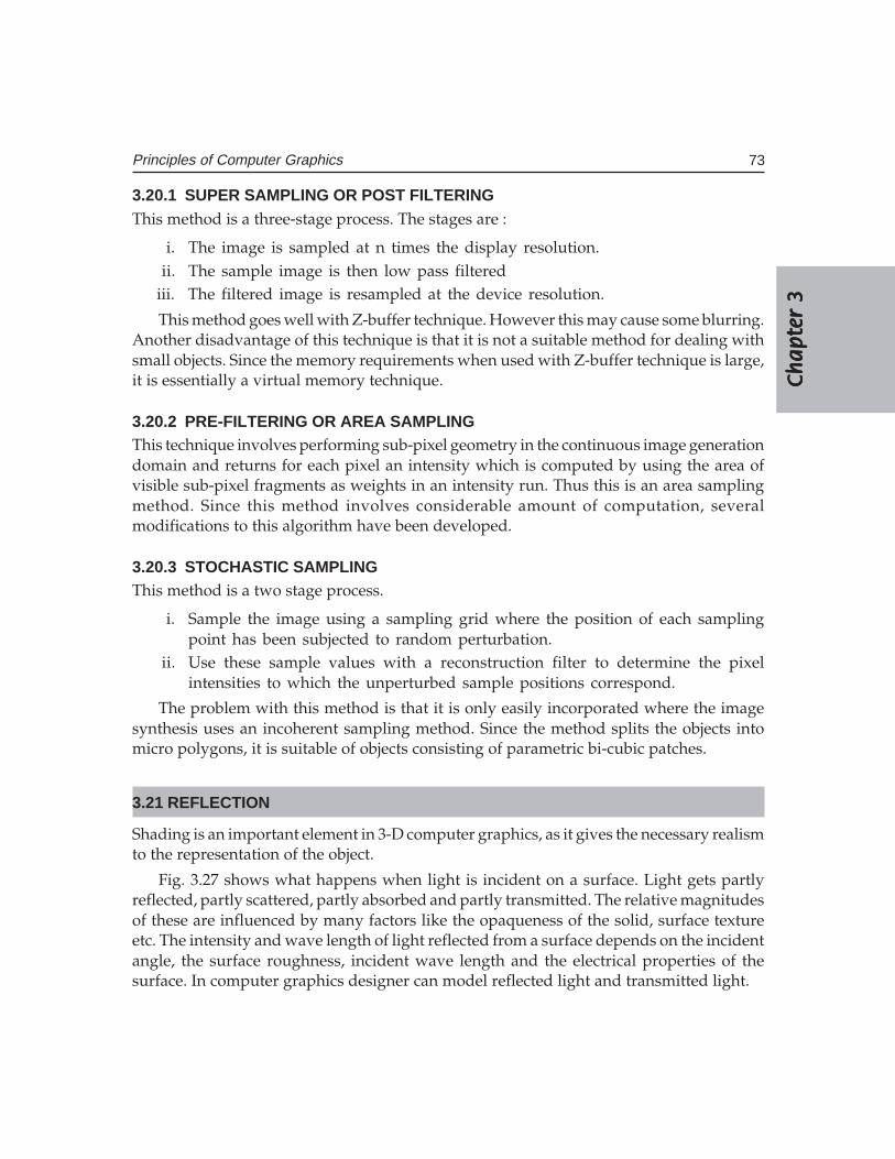
Ch
ap
ter
3C
ha
pte
r 3
Ch
ap
ter
3C
ha
pte
r 3
Ch
ap
ter
3
73Principles of Computer Graphics
3.20.1 SUPER SAMPLING OR POST FILTERINGThis method is a three-stage process. The stages are :
i. The image is sampled at n times the display resolution.ii. The sample image is then low pass filtered
iii. The filtered image is resampled at the device resolution.
This method goes well with Z-buffer technique. However this may cause some blurring.Another disadvantage of this technique is that it is not a suitable method for dealing withsmall objects. Since the memory requirements when used with Z-buffer technique is large,it is essentially a virtual memory technique.
3.20.2 PRE-FILTERING OR AREA SAMPLINGThis technique involves performing sub-pixel geometry in the continuous image generationdomain and returns for each pixel an intensity which is computed by using the area ofvisible sub-pixel fragments as weights in an intensity run. Thus this is an area samplingmethod. Since this method involves considerable amount of computation, severalmodifications to this algorithm have been developed.
3.20.3 STOCHASTIC SAMPLINGThis method is a two stage process.
i. Sample the image using a sampling grid where the position of each samplingpoint has been subjected to random perturbation.
ii. Use these sample values with a reconstruction filter to determine the pixelintensities to which the unperturbed sample positions correspond.
The problem with this method is that it is only easily incorporated where the imagesynthesis uses an incoherent sampling method. Since the method splits the objects intomicro polygons, it is suitable of objects consisting of parametric bi-cubic patches.
3.21 REFLECTION
Shading is an important element in 3-D computer graphics, as it gives the necessary realismto the representation of the object.
Fig. 3.27 shows what happens when light is incident on a surface. Light gets partlyreflected, partly scattered, partly absorbed and partly transmitted. The relative magnitudesof these are influenced by many factors like the opaqueness of the solid, surface textureetc. The intensity and wave length of light reflected from a surface depends on the incidentangle, the surface roughness, incident wave length and the electrical properties of thesurface. In computer graphics designer can model reflected light and transmitted light.
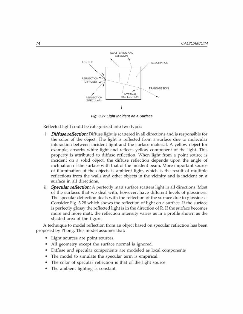
74 CAD/CAM/CIM
SCATTERING ANDEMISSION
INTERNALREFLECTION
TRANSMISSION
REFLECTION(DIFFUSE)
REFLECTION(SPECULAR)
LIGHT IN ABSORPTION
Fig. 3.27 Light Incident on a Surface
Reflected light could be categorized into two types:
i. Diffuse reflection:Diffuse reflection:Diffuse reflection:Diffuse reflection:Diffuse reflection: Diffuse light is scattered in all directions and is responsible forthe color of the object. The light is reflected from a surface due to molecularinteraction between incident light and the surface material. A yellow object forexample, absorbs white light and reflects yellow component of the light. Thisproperty is attributed to diffuse reflection. When light from a point source isincident on a solid object, the diffuse reflection depends upon the angle ofinclination of the surface with that of the incident beam. More important sourceof illumination of the objects is ambient light, which is the result of multiplereflections from the walls and other objects in the vicinity and is incident on asurface in all directions.
ii. Specular reflection:Specular reflection:Specular reflection:Specular reflection:Specular reflection: A perfectly matt surface scatters light in all directions. Mostof the surfaces that we deal with, however, have different levels of glossiness.The specular deflection deals with the reflection of the surface due to glossiness.Consider Fig. 3.28 which shows the reflection of light on a surface. If the surfaceis perfectly glossy the reflected light is in the direction of R. If the surface becomesmore and more matt, the reflection intensity varies as in a profile shown as theshaded area of the figure.
A technique to model reflection from an object based on specular reflection has beenproposed by Phong. This model assumes that:
• Light sources are point sources.• All geometry except the surface normal is ignored.• Diffuse and specular components are modeled as local components• The model to simulate the specular term is empirical.• The color of specular reflection is that of the light source• The ambient lighting is constant.
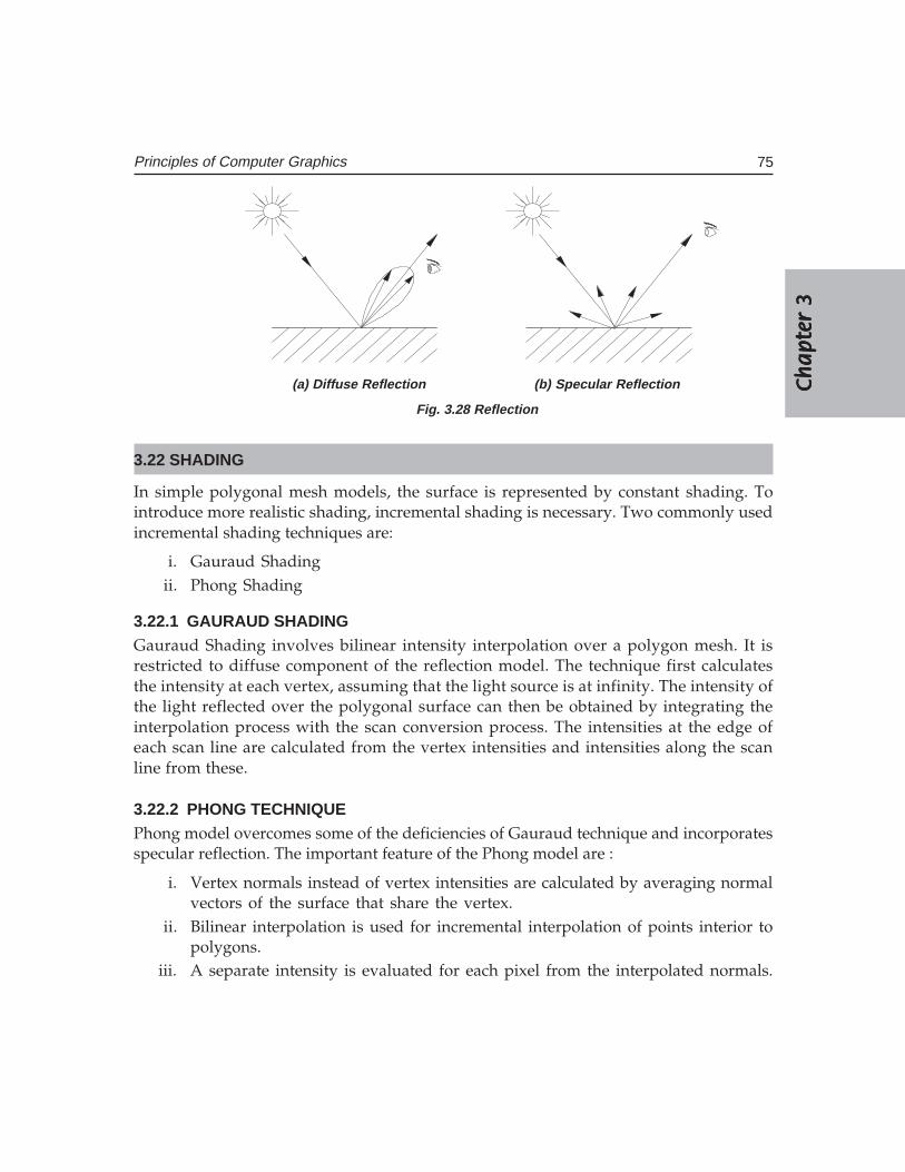
Ch
ap
ter
3C
ha
pte
r 3
Ch
ap
ter
3C
ha
pte
r 3
Ch
ap
ter
3
75Principles of Computer Graphics
(a) Diffuse Reflection (b) Specular Reflection
Fig. 3.28 Reflection
3.22 SHADING
In simple polygonal mesh models, the surface is represented by constant shading. Tointroduce more realistic shading, incremental shading is necessary. Two commonly usedincremental shading techniques are:
i. Gauraud Shadingii. Phong Shading
3.22.1 GAURAUD SHADINGGauraud Shading involves bilinear intensity interpolation over a polygon mesh. It isrestricted to diffuse component of the reflection model. The technique first calculatesthe intensity at each vertex, assuming that the light source is at infinity. The intensity ofthe light reflected over the polygonal surface can then be obtained by integrating theinterpolation process with the scan conversion process. The intensities at the edge ofeach scan line are calculated from the vertex intensities and intensities along the scanline from these.
3.22.2 PHONG TECHNIQUEPhong model overcomes some of the deficiencies of Gauraud technique and incorporatesspecular reflection. The important feature of the Phong model are :
i. Vertex normals instead of vertex intensities are calculated by averaging normalvectors of the surface that share the vertex.
ii. Bilinear interpolation is used for incremental interpolation of points interior topolygons.
iii. A separate intensity is evaluated for each pixel from the interpolated normals.
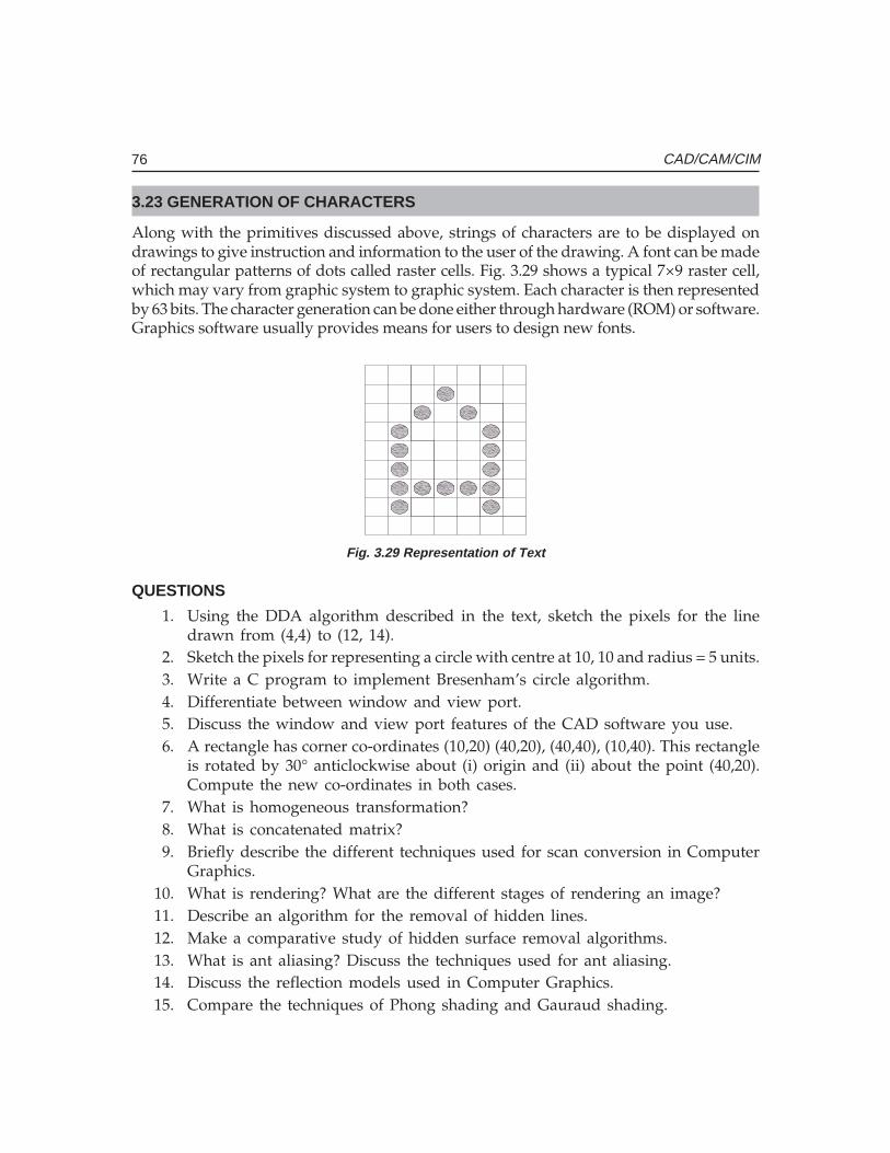
76 CAD/CAM/CIM
3.23 GENERATION OF CHARACTERS
Along with the primitives discussed above, strings of characters are to be displayed ondrawings to give instruction and information to the user of the drawing. A font can be madeof rectangular patterns of dots called raster cells. Fig. 3.29 shows a typical 7×9 raster cell,which may vary from graphic system to graphic system. Each character is then representedby 63 bits. The character generation can be done either through hardware (ROM) or software.Graphics software usually provides means for users to design new fonts.
Fig. 3.29 Representation of Text
QUESTIONS
1. Using the DDA algorithm described in the text, sketch the pixels for the linedrawn from (4,4) to (12, 14).
2. Sketch the pixels for representing a circle with centre at 10, 10 and radius = 5 units.3. Write a C program to implement Bresenham’s circle algorithm.4. Differentiate between window and view port.5. Discuss the window and view port features of the CAD software you use.6. A rectangle has corner co-ordinates (10,20) (40,20), (40,40), (10,40). This rectangle
is rotated by 30° anticlockwise about (i) origin and (ii) about the point (40,20).Compute the new co-ordinates in both cases.
7. What is homogeneous transformation?8. What is concatenated matrix?9. Briefly describe the different techniques used for scan conversion in Computer
Graphics.10. What is rendering? What are the different stages of rendering an image?11. Describe an algorithm for the removal of hidden lines.12. Make a comparative study of hidden surface removal algorithms.13. What is ant aliasing? Discuss the techniques used for ant aliasing.14. Discuss the reflection models used in Computer Graphics.15. Compare the techniques of Phong shading and Gauraud shading.
������������ ���
������
Various types of computers and peripherals are used in CIM. Depending on the size of theorganization the type and configuration of computer system vary widely. Computers withspecial capabilities are recommended for tasks like design and analysis involving very highorder of number crunching. This chapter gives a brief account of personal computers andRISC-based design workstations. The commonly used input and output peripherals are alsodiscussed in detail.
4.1 INTRODUCTION
There are two basic components in a computer system used in CIM. They are:
i. Computer Hardwareii. Software
Hardware consists of the various types of computers like personal computers, (PCs),graphics workstations, input devices like mouse, keyboard and digitizer and output deviceslike plotter and printer.
Computer software includes:Computer software includes:Computer software includes:Computer software includes:Computer software includes:
i. The operating system which controls the basic house-keeping operations in acomputer.
ii. Software packages used for conceptual design like Alias and for geometricmodeling like solid modeling (Solid Works, Unigraphics, CATIA, Pro/Engineeretc).
iii. Application software which includes the programs for design analysis, simulationand synthesis, tool design, process planning, enterprise resource planning, PDM,PLM, CNC programming, computer aided inspection etc. These also cover finiteelement analysis, kinematics analysis, piping design, architecture, PCB design,VLSI design, computational fluid dynamics, expert systems, and severalapplication-specific software packages.
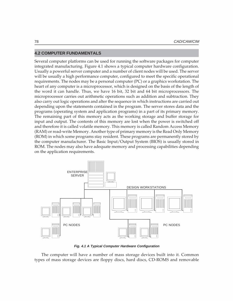
78 CAD/CAM/CIM
4.2 COMPUTER FUNDAMENTALS
Several computer platforms can be used for running the software packages for computerintegrated manufacturing. Figure 4.1 shows a typical computer hardware configuration.Usually a powerful server computer and a number of client nodes will be used. The serverwill be usually a high performance computer, configured to meet the specific operationalrequirements. The nodes may be a personal computer (PC) or a graphics workstation. Theheart of any computer is a microprocessor, which is designed on the basis of the length ofthe word it can handle. Thus, we have 16 bit, 32 bit and 64 bit microprocessors. Themicroprocessor carries out arithmetic operations such as addition and subtraction. Theyalso carry out logic operations and alter the sequence in which instructions are carried outdepending upon the statements contained in the program. The server stores data and theprograms (operating system and application programs) in a part of its primary memory.The remaining part of this memory acts as the working storage and buffer storage forinput and output. The contents of this memory are lost when the power is switched offand therefore it is called volatile memory. This memory is called Random Access Memory(RAM) or read-write Memory. Another type of primary memory is the Read Only Memory(ROM) in which some programs stay resident. These programs are permanently stored bythe computer manufacturer. The Basic Input/Output System (BIOS) is usually stored inROM. The nodes may also have adequate memory and processing capabilities dependingon the application requirements.
ENTERPRISESERVER
DESIGN WORKSTATIONS
PC NODES PC NODES
Fig. 4.1 A Typical Computer Hardware Configuration
The computer will have a number of mass storage devices built into it. Commontypes of mass storage devices are floppy discs, hard discs, CD-ROMS and removable
Ch
ap
ter
4C
ha
pte
r 4
Ch
ap
ter
4C
ha
pte
r 4
Ch
ap
ter
4
79Computer Hardware
storage devices. Another type of mass storage device is the cartridge tape. Softwares areusually stored in the hard disc and they can be loaded into the primary memory as andwhen required. In a networked environment, the software is stored in the hard disc of theserver and the users can access the software from the different terminals or nodes connectedto the server. Hard discs are also used for storing data files, drawing files and other relatedfiles. A magnetic tape is used to backup the files so that vital files and information are notlost in the event of a disc failure. Optical discs (CD-ROMs) are widely used nowadays formass storage.
The display of the programs and drawing is done on the monitor. Several types ofmonitors or video display units (VDU’s) are used as display devices. These includemonochrome and color monitors. Super Video Graphics Array (SVGA) is the type ofmonitor that is widely used on PC’s today. A number of input devices are also used, themost popular being the ubiquitous mouse, used for command input, menu selection orpointing on the screen. The keyboard is indispensable for computer operation and isused for command input. A digitizer tablet is also a convenient input device, often usedin design. Special input devices are used in laptop computers. Hard copy outputs areusually taken on a plotter. Printed reports and files and print plot drawings can beobtained using a printer.
4.3 CLASSIFICATION OF COMPUTERS
Computers are commonly divided into the following types:
i. Personal Computer or Microcomputersii. Mini Computers
iii. Mainframesiv. Supercomputers
Today the distinction between various types is blurring with advances in microprocessorand microelectronics technologies and processing approaches. Processing speed, accessiblememory and cost are the factors used to classify computers. Both processing speed andmemory depend on word length.
4.3.1 MICRO COMPUTERS AND PERSONAL COMPUTERSThe personal computers are so named because these were originally developed as asingle user desk-top system to increase the productivity of employees. Apple ComputerCompany is the pioneer in popularizing PC’s. IBM introduced their personal computerin the year 1981 and presently IBM or their licensees and Apple Computers (Macintoshseries of computers) are the major computer companies who are world leaders in thePC market. Many dedicated microcomputers and super micros optimized for CADapplications are now sold as Windows NT based graphic workstations. The IBMpersonal computer and the microcomputers that run on the same software (called

80 CAD/CAM/CIM
compatibles) are very popular with designers. These systems have a powerful CPU,and a fast system clock (a timing signal that co-ordinates the data flow in CPU) of 2.8GHz or even higher. Most Personal Computers (PC’s) are designed around a singleprocessor chip as CPU which will have either 32 or 64 bit word length. Presently theminimum memory quoted on a low end PC (Pentium 4 at 2.8 GHz) is 512 MB. ThesePC’s are based on 32 bit 80586 microprocessors.
Most CAD applications require at least one floppy disc (storage capacity of 1.44 MB)drive and a hard disc drive which storage capacity starting from 40 GB and a CD-ROMdrive. The relatively fast access speed of hard disc drive is particularly useful in CIM.Personal computers are also often used as front-end systems of many turnkey CIM systemswhere more powerful computers are used for data intensive activities like finite elementanalysis. Several computer companies manufacture IBM PC compatible computers in India.Notable among them are HCL, HP, Wipro, Zenith etc.
Table 4.1 gives the specifications of a typical personal computer.
4.3.2 OVERVIEW OF PENTIUM PCThe hardware of a Pentium computer consists of the following:
i. Mother boardii. Hard disc/floppy disc controller card
iii. Graphics adapter cardiv. Input/Output cardv. Switch mode power supply
vi. Floppy disc drivevii. Hard disc drive
viii. CD-ROM drive
Table 4.1 Specifications of a Typical PC
2.8 GHz or faster CPUATX Motherboard with on board LAN or network adapter512 MB RAM40 GB or higher 7200 rpm IDE hard disc drive1.44 MB 3.5" Floppy disc driveCD- RW 40 X Read, 24X Write, 10 X Rewrite drive17’’ LCD Monitor or 17’’ CRT MonitorOn- board sound or Creative Live sound card and amplified speakersPS2 Key Board and MousenVidia GeForce video card, on board Intel Extreme Graphics Card
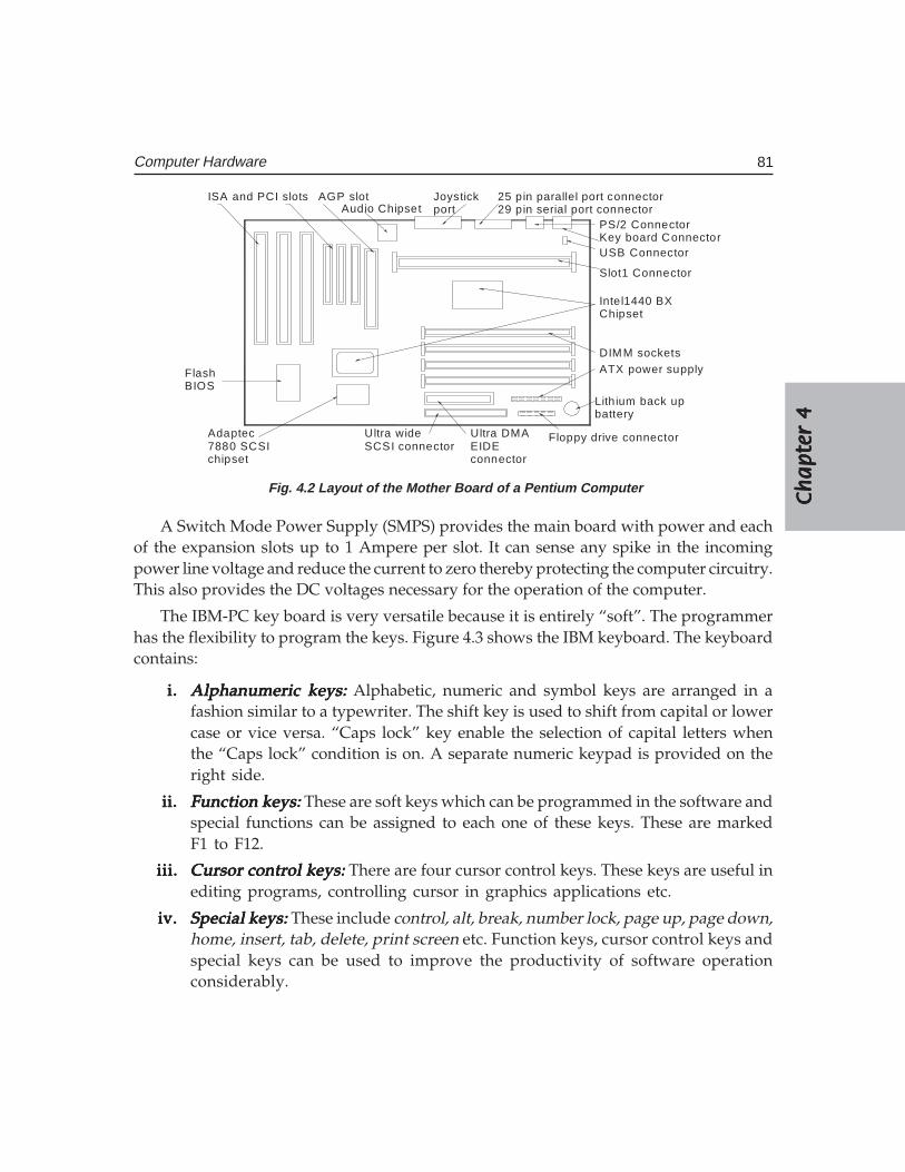
Ch
ap
ter
4C
ha
pte
r 4
Ch
ap
ter
4C
ha
pte
r 4
Ch
ap
ter
4
81Computer Hardware
ISA and PCI slots AGP slotAudio Chipset
Joystickport
25 pin parallel port connector29 pin serial port connector
PS/2 ConnectorKey board ConnectorUSB Connector
Slot1 Connector
Intel1440 BXChipset
DIMM socketsATX power supply
Lith ium back upbattery
Floppy drive connectorUltra DMAEIDEconnector
Ultra wideSCSI connector
Adaptec7880 SCSIchipset
FlashBIOS
Fig. 4.2 Layout of the Mother Board of a Pentium Computer
A Switch Mode Power Supply (SMPS) provides the main board with power and eachof the expansion slots up to 1 Ampere per slot. It can sense any spike in the incomingpower line voltage and reduce the current to zero thereby protecting the computer circuitry.This also provides the DC voltages necessary for the operation of the computer.
The IBM-PC key board is very versatile because it is entirely “soft”. The programmerhas the flexibility to program the keys. Figure 4.3 shows the IBM keyboard. The keyboardcontains:
i.i.i.i.i. Alphanumeric keys:Alphanumeric keys:Alphanumeric keys:Alphanumeric keys:Alphanumeric keys: Alphabetic, numeric and symbol keys are arranged in afashion similar to a typewriter. The shift key is used to shift from capital or lowercase or vice versa. “Caps lock” key enable the selection of capital letters whenthe “Caps lock” condition is on. A separate numeric keypad is provided on theright side.
ii.ii.ii.ii.ii. Function keys:Function keys:Function keys:Function keys:Function keys: These are soft keys which can be programmed in the software andspecial functions can be assigned to each one of these keys. These are markedF1 to F12.
iii.iii.iii.iii.iii. Cursor control keys:Cursor control keys:Cursor control keys:Cursor control keys:Cursor control keys: There are four cursor control keys. These keys are useful inediting programs, controlling cursor in graphics applications etc.
iv.iv.iv.iv.iv. Special keys: Special keys: Special keys: Special keys: Special keys: These include control, alt, break, number lock, page up, page down,home, insert, tab, delete, print screen etc. Function keys, cursor control keys andspecial keys can be used to improve the productivity of software operationconsiderably.
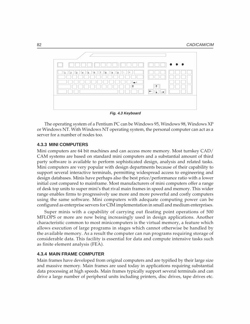
82 CAD/CAM/CIM
1 2 3 4 5 6 7 8 9 0 - =
Fig. 4.3 Keyboard
The operating system of a Pentium PC can be Windows 95, Windows 98, Windows XPor Windows NT. With Windows NT operating system, the personal computer can act as aserver for a number of nodes too.
4.3.3 MINI COMPUTERSMini computers are 64 bit machines and can access more memory. Most turnkey CAD/CAM systems are based on standard mini computers and a substantial amount of thirdparty software is available to perform sophisticated design, analysis and related tasks.Mini computers are very popular with design departments because of their capability tosupport several interactive terminals, permitting widespread access to engineering anddesign databases. Minis have perhaps also the best price/performance ratio with a lowerinitial cost compared to mainframe. Most manufacturers of mini computers offer a rangeof desk top units to super mini’s that rival main frames in speed and memory. This widerrange enables firms to progressively use more and more powerful and costly computersusing the same software. Mini computers with adequate computing power can beconfigured as enterprise servers for CIM implementation in small and medium enterprises.
Super minis with a capability of carrying out floating point operations of 500MFLOPS or more are now being increasingly used in design applications. Anothercharacteristic common to most minicomputers is the virtual memory, a feature whichallows execution of large programs in stages which cannot otherwise be handled bythe available memory. As a result the computer can run programs requiring storage ofconsiderable data. This facility is essential for data and compute intensive tasks suchas finite element analysis (FEA).
4.3.4 MAIN FRAME COMPUTERMain frames have developed from original computers and are typified by their large sizeand massive memory. Main frames are used today in applications requiring substantialdata processing at high speeds. Main frames typically support several terminals and candrive a large number of peripheral units including printers, disc drives, tape drives etc.
Ch
ap
ter
4C
ha
pte
r 4
Ch
ap
ter
4C
ha
pte
r 4
Ch
ap
ter
4
83Computer Hardware
Large memory is an essential requirement of main frames as they are frequently used fordata intensive operations like design analysis, database management, weather forecasting,traffic and financial operations. Main frames can operate in batch mode or can be used ina time-sharing environment. Main frames are often used to provide processing powerafter a problem has been set up with a personal computer or mini computer. Main framesare also linked to several smaller computers, which enable the latter to access the largedata base of the main frames. This feature is particularly advantageous for design in largedesign offices where a single data base environment is desirable. The work stations locatedin the design offices can access the main frame computer of the company for analysis anddata, thereby simpler design analysis and drafting are done locally and part of the dataintensive design analysis like FEA and solid modeling are carried out at the main frame.For large enterprises, mainframe based computing environment could be a cost effectivesolution for implementing CIM.
4.3.5 SUPER COMPUTERSSuper computers take advantage of the most recent advancement in electronic circuit design,processing techniques and memory organization to attain computing speeds many timesthat of main frames. Typically main frames operate at a few megaflops (one megaflop is amillion floating point operations per second) whereas supercomputers can have speedsbetween 20-400 megaflops.
Though these computers are priced very high, because of their high processing speed,the processing cost may be low even in the case of very complex CAD applications whichrequire evaluation of several alternatives or which require several iterations to be carriedout. Applications of super computers include modeling and simulation tasks such as solidmodeling, kinematical analysis , modal analysis, finite element analysis and computationalfluid dynamics. An advantage of supercomputers is the vector processing facility whichcan drastically increase computing speed. Data pipelining, high speed circuits and largeinternal memories enable complex design and analysis operations handled conveniently.The performance of a supercomputer can also be achieved by using several processorsworking in parallel mode.
4.4 DATA COMMUNICATIONS
Computers need to communicate with printers, terminals and other computers. This kindof input/output is typically called data communications, since streams of data aretransferred between sources and destinations. This flow must be synchronized. This istypically done under the control of “handshaking” conventions that use either dedicatedhardware lines or special character sequences. A simple example of handshaking involvesa printer capable of printing only 120 characters per second, but receiving data at 10 timesthat rate. When the printer’s input buffer is full, it sends a busy signal to the data source(by pulling high a line connecting the two), indicating that it cannot accept any more data
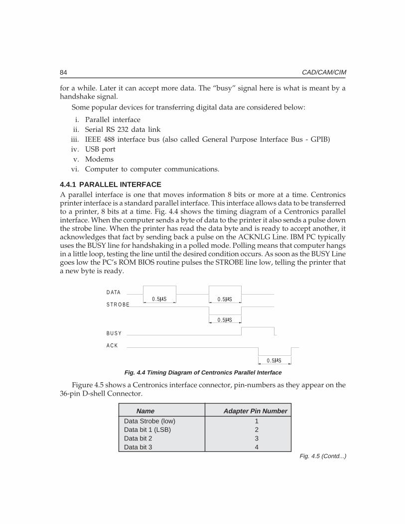
84 CAD/CAM/CIM
for a while. Later it can accept more data. The “busy” signal here is what is meant by ahandshake signal.
Some popular devices for transferring digital data are considered below:
i. Parallel interfaceii. Serial RS 232 data link
iii. IEEE 488 interface bus (also called General Purpose Interface Bus - GPIB)iv. USB portv. Modems
vi. Computer to computer communications.
4.4.1 PARALLEL INTERFACEA parallel interface is one that moves information 8 bits or more at a time. Centronicsprinter interface is a standard parallel interface. This interface allows data to be transferredto a printer, 8 bits at a time. Fig. 4.4 shows the timing diagram of a Centronics parallelinterface. When the computer sends a byte of data to the printer it also sends a pulse downthe strobe line. When the printer has read the data byte and is ready to accept another, itacknowledges that fact by sending back a pulse on the ACKNLG Line. IBM PC typicallyuses the BUSY line for handshaking in a polled mode. Polling means that computer hangsin a little loop, testing the line until the desired condition occurs. As soon as the BUSY Linegoes low the PC’s ROM BIOS routine pulses the STROBE line low, telling the printer thata new byte is ready.
D ATA
S T R O B E
B U S Y
0 .5 S 0 .5 S
0 .5 S
0 .5 S
A C K
µ µ
µ
µ
Fig. 4.4 Timing Diagram of Centronics Parallel Interface
Figure 4.5 shows a Centronics interface connector, pin-numbers as they appear on the36-pin D-shell Connector.
Name Adapter Pin NumberData Strobe (low) 1Data bit 1 (LSB) 2Data bit 2 3Data bit 3 4
Fig. 4.5 (Contd...)
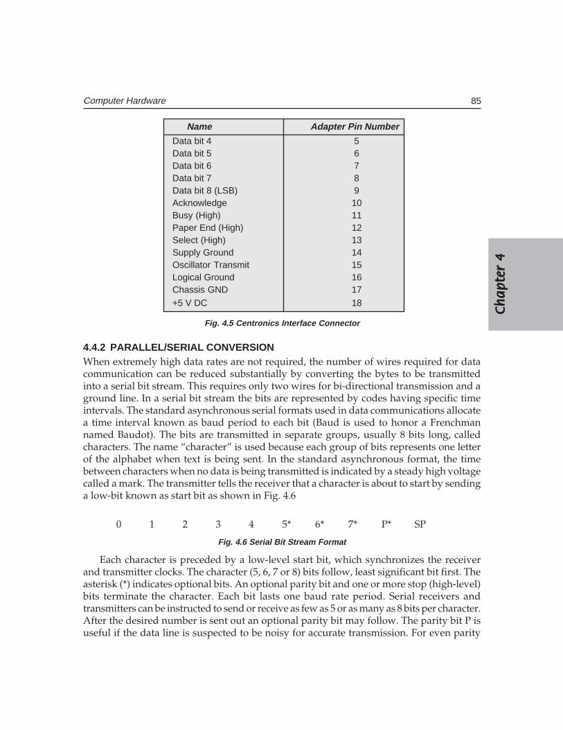
Ch
ap
ter
4C
ha
pte
r 4
Ch
ap
ter
4C
ha
pte
r 4
Ch
ap
ter
4
85Computer Hardware
Name Adapter Pin Number
Data bit 4 5Data bit 5 6Data bit 6 7Data bit 7 8Data bit 8 (LSB) 9Acknowledge 10Busy (High) 11Paper End (High) 12Select (High) 13Supply Ground 14Oscillator Transmit 15Logical Ground 16Chassis GND 17+5 V DC 18
Fig. 4.5 Centronics Interface Connector
4.4.2 PARALLEL/SERIAL CONVERSIONWhen extremely high data rates are not required, the number of wires required for datacommunication can be reduced substantially by converting the bytes to be transmittedinto a serial bit stream. This requires only two wires for bi-directional transmission and aground line. In a serial bit stream the bits are represented by codes having specific timeintervals. The standard asynchronous serial formats used in data communications allocatea time interval known as baud period to each bit (Baud is used to honor a Frenchmannamed Baudot). The bits are transmitted in separate groups, usually 8 bits long, calledcharacters. The name “character” is used because each group of bits represents one letterof the alphabet when text is being sent. In the standard asynchronous format, the timebetween characters when no data is being transmitted is indicated by a steady high voltagecalled a mark. The transmitter tells the receiver that a character is about to start by sendinga low-bit known as start bit as shown in Fig. 4.6
0 1 2 3 4 5* 6* 7* P* SP
Fig. 4.6 Serial Bit Stream Format
Each character is preceded by a low-level start bit, which synchronizes the receiverand transmitter clocks. The character (5, 6, 7 or 8) bits follow, least significant bit first. Theasterisk (*) indicates optional bits. An optional parity bit and one or more stop (high-level)bits terminate the character. Each bit lasts one baud rate period. Serial receivers andtransmitters can be instructed to send or receive as few as 5 or as many as 8 bits per character.After the desired number is sent out an optional parity bit may follow. The parity bit P isuseful if the data line is suspected to be noisy for accurate transmission. For even parity
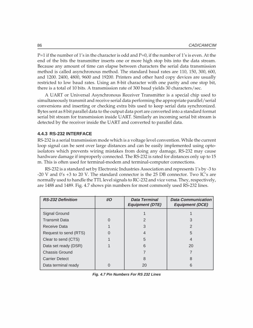
86 CAD/CAM/CIM
P=1 if the number of 1’s in the character is odd and P=0, if the number of 1’s is even. At theend of the bits the transmitter inserts one or more high stop bits into the data stream.Because any amount of time can elapse between characters the serial data transmissionmethod is called asynchronous method. The standard baud rates are 110, 150, 300, 600,and 1200. 2400, 4800, 9600 and 19200. Printers and other hard copy devices are usuallyrestricted to low baud rates. Using an 8-bit character with one parity and one stop bit,there is a total of 10 bits. A transmission rate of 300 baud yields 30 characters/sec.
A UART or Universal Asynchronous Receiver Transmitter is a special chip used tosimultaneously transmit and receive serial data performing the appropriate parallel/serialconversions and inserting or checking extra bits used to keep serial data synchronized.Bytes sent as 8 bit parallel data to the output data port are converted into a standard formatserial bit stream for transmission inside UART. Similarly an incoming serial bit stream isdetected by the receiver inside the UART and converted to parallel data.
4.4.3 RS-232 INTERFACERS-232 is a serial transmission mode which is a voltage level convention. While the currentloop signal can be sent over large distances and can be easily implemented using opto-isolators which prevents wiring mistakes from doing any damage, RS-232 may causehardware damage if improperly connected. The RS-232 is rated for distances only up to 15m. This is often used for terminal-modem and terminal-computer connections.
RS-232 is a standard set by Electronic Industries Association and represents 1’s by -3 to-20 V and 0’s +3 to 20 V. The standard connector is the 25 DB connector. Two IC’s arenormally used to handle the TTL level signals to RC-232 and vice versa. They, respectively,are 1488 and 1489. Fig. 4.7 shows pin numbers for most commonly used RS-232 lines.
Fig. 4.7 Pin Numbers For RS 232 Lines
RS-232 Definition I/O Data Terminal Data CommunicationEquipment (DTE) Equipment (DCE)
Signal Ground 1 1
Transmit Data 0 2 3
Receive Data 1 3 2
Request to send (RTS) 0 4 5
Clear to send (CTS) 1 5 4
Data set ready (DSR) 1 6 20
Chassis Ground 7 7
Carrier Detect 8 8
Data terminal ready 0 20 6
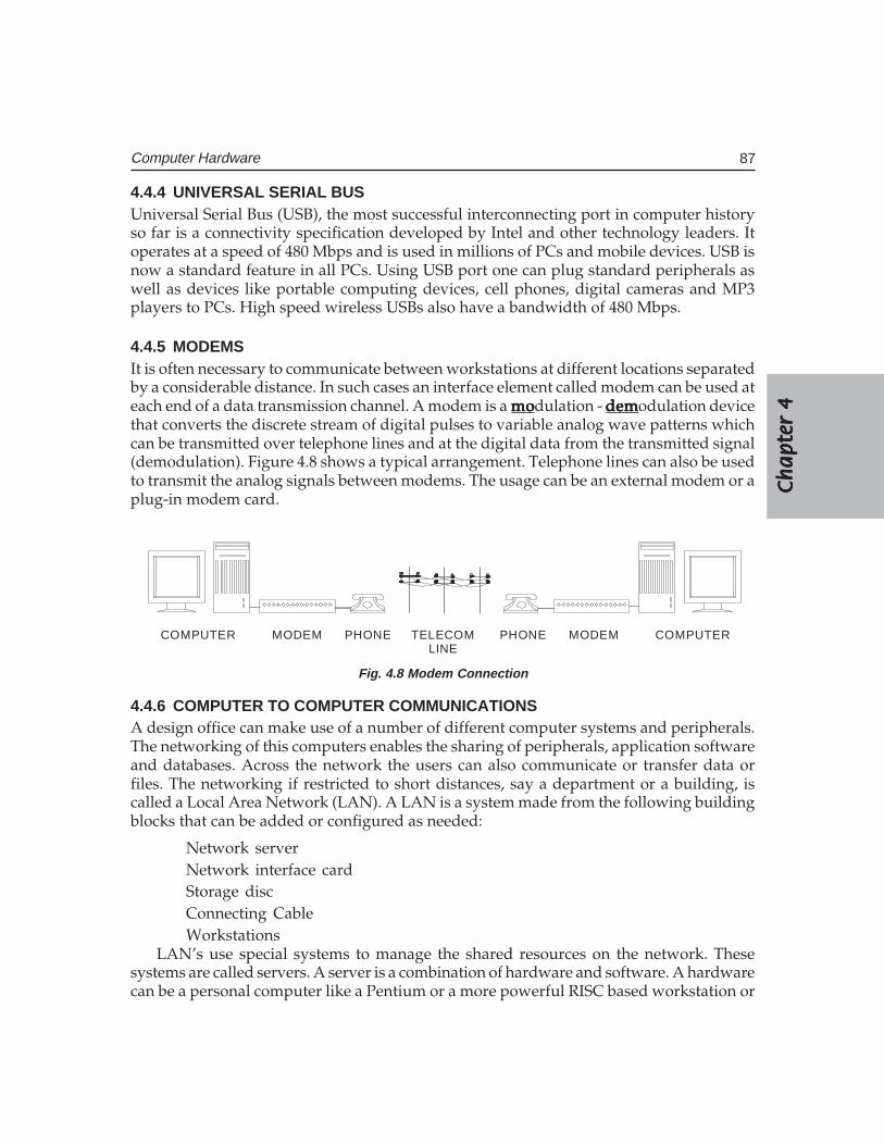
Ch
ap
ter
4C
ha
pte
r 4
Ch
ap
ter
4C
ha
pte
r 4
Ch
ap
ter
4
87Computer Hardware
4.4.4 UNIVERSAL SERIAL BUSUniversal Serial Bus (USB), the most successful interconnecting port in computer historyso far is a connectivity specification developed by Intel and other technology leaders. Itoperates at a speed of 480 Mbps and is used in millions of PCs and mobile devices. USB isnow a standard feature in all PCs. Using USB port one can plug standard peripherals aswell as devices like portable computing devices, cell phones, digital cameras and MP3players to PCs. High speed wireless USBs also have a bandwidth of 480 Mbps.
4.4.5 MODEMSIt is often necessary to communicate between workstations at different locations separatedby a considerable distance. In such cases an interface element called modem can be used ateach end of a data transmission channel. A modem is a momomomomodulation - demdemdemdemdemodulation devicethat converts the discrete stream of digital pulses to variable analog wave patterns whichcan be transmitted over telephone lines and at the digital data from the transmitted signal(demodulation). Figure 4.8 shows a typical arrangement. Telephone lines can also be usedto transmit the analog signals between modems. The usage can be an external modem or aplug-in modem card.
COMPUTER MODEM PHONE TELECOMLINE
PHONE MODEM COMPUTER
Fig. 4.8 Modem Connection
4.4.6 COMPUTER TO COMPUTER COMMUNICATIONSA design office can make use of a number of different computer systems and peripherals.The networking of this computers enables the sharing of peripherals, application softwareand databases. Across the network the users can also communicate or transfer data orfiles. The networking if restricted to short distances, say a department or a building, iscalled a Local Area Network (LAN). A LAN is a system made from the following buildingblocks that can be added or configured as needed:
Network serverNetwork interface cardStorage discConnecting CableWorkstations
LAN’s use special systems to manage the shared resources on the network. Thesesystems are called servers. A server is a combination of hardware and software. A hardwarecan be a personal computer like a Pentium or a more powerful RISC based workstation or
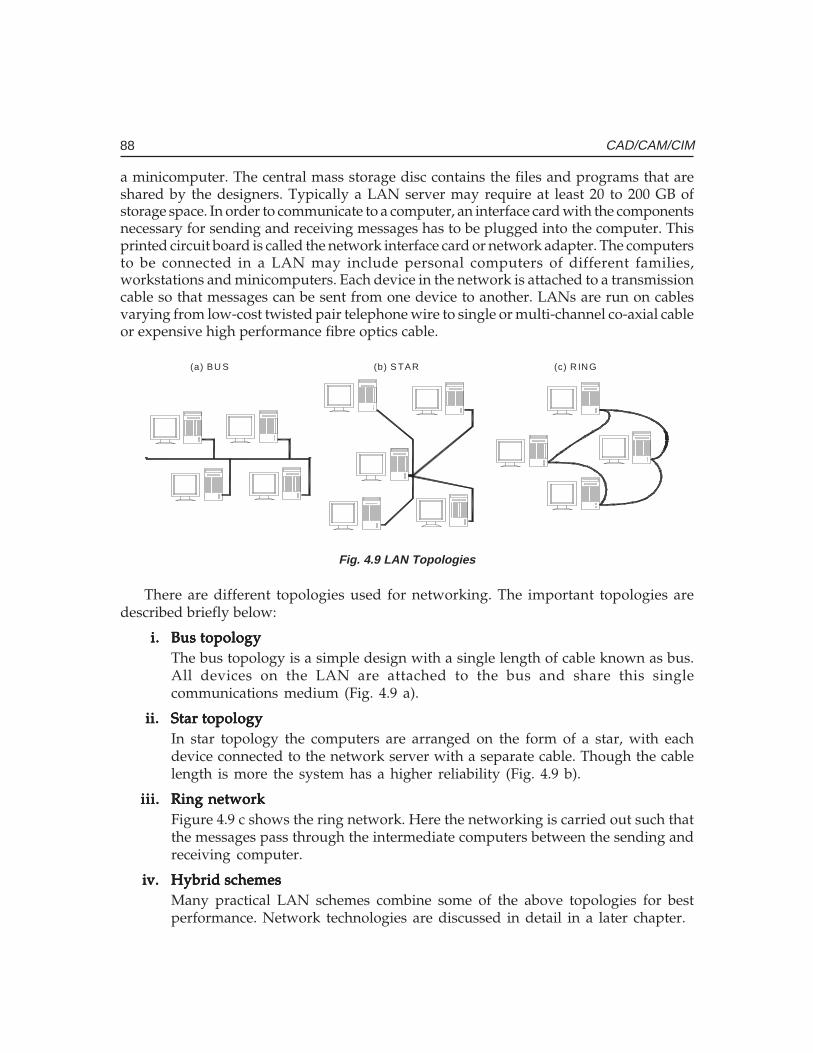
88 CAD/CAM/CIM
a minicomputer. The central mass storage disc contains the files and programs that areshared by the designers. Typically a LAN server may require at least 20 to 200 GB ofstorage space. In order to communicate to a computer, an interface card with the componentsnecessary for sending and receiving messages has to be plugged into the computer. Thisprinted circuit board is called the network interface card or network adapter. The computersto be connected in a LAN may include personal computers of different families,workstations and minicomputers. Each device in the network is attached to a transmissioncable so that messages can be sent from one device to another. LANs are run on cablesvarying from low-cost twisted pair telephone wire to single or multi-channel co-axial cableor expensive high performance fibre optics cable.
(a) BU S (b) S TAR (c) R IN G
Fig. 4.9 LAN Topologies
There are different topologies used for networking. The important topologies aredescribed briefly below:
i.i.i.i.i. Bus topologyBus topologyBus topologyBus topologyBus topologyThe bus topology is a simple design with a single length of cable known as bus.All devices on the LAN are attached to the bus and share this singlecommunications medium (Fig. 4.9 a).
ii.ii.ii.ii.ii. Star topologyStar topologyStar topologyStar topologyStar topologyIn star topology the computers are arranged on the form of a star, with eachdevice connected to the network server with a separate cable. Though the cablelength is more the system has a higher reliability (Fig. 4.9 b).
iii.iii.iii.iii.iii. Ring networkRing networkRing networkRing networkRing networkFigure 4.9 c shows the ring network. Here the networking is carried out such thatthe messages pass through the intermediate computers between the sending andreceiving computer.
iv.iv.iv.iv.iv. Hybrid schemesHybrid schemesHybrid schemesHybrid schemesHybrid schemesMany practical LAN schemes combine some of the above topologies for bestperformance. Network technologies are discussed in detail in a later chapter.
Ch
ap
ter
4C
ha
pte
r 4
Ch
ap
ter
4C
ha
pte
r 4
Ch
ap
ter
4
89Computer Hardware
A typical workstation will have the following networking features as options:
• Ethernet networking connector• Asynchronous and synchronous communication ports• Transmission control protocol/Internet protocol (TCP/IP) or XNS• ISO/OSI, SNA, DEC net, Netware.
v.v.v.v.v. Wireless LAN (WLAN)Wireless LAN (WLAN)Wireless LAN (WLAN)Wireless LAN (WLAN)Wireless LAN (WLAN)Wireless LAN extends the reach of existing wired networks through high frequencyradio waves to the entire organization. This is also known as Wi-Fi. IEEE 802.11is the set of standards for Wireless Local Area Networks. Each computer, mobile,portable or fixed is referred to as a station in 802.11. Portable stations can be usedonly at fixed points. Mobile stations can access the LAN even while moving. Whentwo or more stations come together to communicate with each other, they constitutea basic service set (BSS). A BSS that stands alone (not connected to a base) is calledan Independent Basic Service Set (IBSS). It is also referred to as an Ad-Hoc network.In an ad-hoc network stations are connected only peer to peer. Two or more BSS’sare interconnected using a Distribution System (DS). Entry into DS is accomplishedusing an Access Point (AP). Large and complex networks could be created usingseveral BSS’s and DS’s.
4.5 DESIGN WORK STATIONS
Engineering workstations are computer systems with adequate computing power, basedon 32 or 64 bit microprocessors. Workstations are typically divided into two broadcategories: Low-end and high-end.
Low-end work stations generally consist of personal computers. Appropriate softwareand special hardware like graphics accelerator cards are added to these for boosting theperformance. Personal computers have the additional advantage of being able to run asubstantial amount of software such as programs for analysis, database management, etc.The processing capability of personal computers is generally enhanced by the addition ofa co-processor in the microprocessor circuit which increases the processing speed by twoor three times. Special custom-built graphics boards increase resolution and decreasedrawing times. High resolution color monitors and multifunction cards improve theversatility of personal computers.
High-end workstations are designed around one or more powerful RISC processors.Examples of such processors are PA-RISC, MIPS, and SPARC etc. Hardware in these systemsgenerally consists of high resolution graphics display of 1024 X 1024 pixels, or more, aprocessor capable of 2 to 4 MIPS or more and 512 MB to 8GB core memory and massstorage in the range of 36-146 GB (Giga Byte), with optional magnetic tape back up. Thesewill also have the ability to operate in a computer net work with other workstations or towork as host computers, to PC nodes which may be intelligent or dumb.
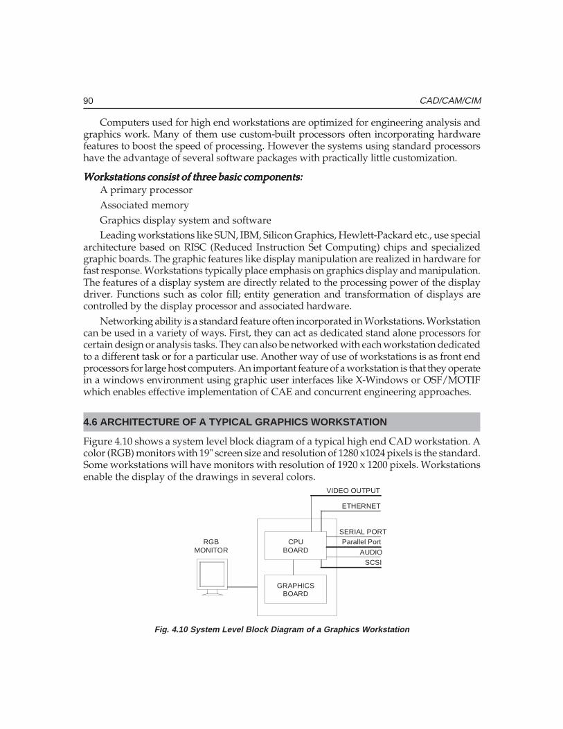
90 CAD/CAM/CIM
Computers used for high end workstations are optimized for engineering analysis andgraphics work. Many of them use custom-built processors often incorporating hardwarefeatures to boost the speed of processing. However the systems using standard processorshave the advantage of several software packages with practically little customization.
Workstations consist of three basic components:Workstations consist of three basic components:Workstations consist of three basic components:Workstations consist of three basic components:Workstations consist of three basic components:A primary processorAssociated memoryGraphics display system and softwareLeading workstations like SUN, IBM, Silicon Graphics, Hewlett-Packard etc., use special
architecture based on RISC (Reduced Instruction Set Computing) chips and specializedgraphic boards. The graphic features like display manipulation are realized in hardware forfast response. Workstations typically place emphasis on graphics display and manipulation.The features of a display system are directly related to the processing power of the displaydriver. Functions such as color fill; entity generation and transformation of displays arecontrolled by the display processor and associated hardware.
Networking ability is a standard feature often incorporated in Workstations. Workstationcan be used in a variety of ways. First, they can act as dedicated stand alone processors forcertain design or analysis tasks. They can also be networked with each workstation dedicatedto a different task or for a particular use. Another way of use of workstations is as front endprocessors for large host computers. An important feature of a workstation is that they operatein a windows environment using graphic user interfaces like X-Windows or OSF/MOTIFwhich enables effective implementation of CAE and concurrent engineering approaches.
4.6 ARCHITECTURE OF A TYPICAL GRAPHICS WORKSTATION
Figure 4.10 shows a system level block diagram of a typical high end CAD workstation. Acolor (RGB) monitors with 19" screen size and resolution of 1280 x1024 pixels is the standard.Some workstations will have monitors with resolution of 1920 x 1200 pixels. Workstationsenable the display of the drawings in several colors.
CPUBOARD
GRAPHICSBOARD
VIDEO OUTPUT
ETHERNET
SERIAL PORTParallel Port
AUDIOSCSI
RGBMONITOR
Fig. 4.10 System Level Block Diagram of a Graphics Workstation
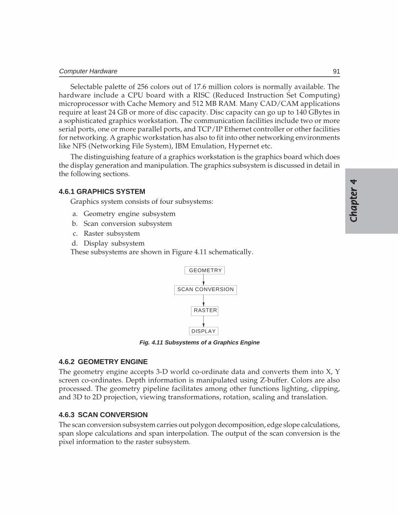
Ch
ap
ter
4C
ha
pte
r 4
Ch
ap
ter
4C
ha
pte
r 4
Ch
ap
ter
4
91Computer Hardware
Selectable palette of 256 colors out of 17.6 million colors is normally available. Thehardware include a CPU board with a RISC (Reduced Instruction Set Computing)microprocessor with Cache Memory and 512 MB RAM. Many CAD/CAM applicationsrequire at least 24 GB or more of disc capacity. Disc capacity can go up to 140 GBytes ina sophisticated graphics workstation. The communication facilities include two or moreserial ports, one or more parallel ports, and TCP/IP Ethernet controller or other facilitiesfor networking. A graphic workstation has also to fit into other networking environmentslike NFS (Networking File System), IBM Emulation, Hypernet etc.
The distinguishing feature of a graphics workstation is the graphics board which doesthe display generation and manipulation. The graphics subsystem is discussed in detail inthe following sections.
4.6.1 GRAPHICS SYSTEMGraphics system consists of four subsystems:
a. Geometry engine subsystemb. Scan conversion subsystemc. Raster subsystemd. Display subsystemThese subsystems are shown in Figure 4.11 schematically.
GEOMETRY
SCAN CONVERSION
RASTER
DISPLAY
Fig. 4.11 Subsystems of a Graphics Engine
4.6.2 GEOMETRY ENGINEThe geometry engine accepts 3-D world co-ordinate data and converts them into X, Yscreen co-ordinates. Depth information is manipulated using Z-buffer. Colors are alsoprocessed. The geometry pipeline facilitates among other functions lighting, clipping,and 3D to 2D projection, viewing transformations, rotation, scaling and translation.
4.6.3 SCAN CONVERSIONThe scan conversion subsystem carries out polygon decomposition, edge slope calculations,span slope calculations and span interpolation. The output of the scan conversion is thepixel information to the raster subsystem.

92 CAD/CAM/CIM
4.6.4 RASTER SUBSYSTEMThe raster subsystem will have usually 24 bit planes. This will provide eight bit planes foreach primary color (RGB) so that (28) shades of a single color can thus obtain.
Since the different colors are obtained by the three primary colors a total of (28)3colorsare available on the screen.
In a typical raster engine five 256K X 4D RAM provide 4 bits of Z-depth. The rasterinformation is stored in the frame buffer. Twenty 64 K X 4 video RAM provide 4 bits foreach pixel of 1280 X 1024 resolution. Entry level systems will have 12 bit planes and highend systems will have 32 bit planes for the frame buffer. These provide the color anddepth for the images.
4.6.5 DISPLAY SUBSYSTEMThe display subsystem has multi-mode graphics processors which manage the display,send the Red, Green, Blue color (RGB) data to the respective digital to analog converters aswell as provide a video output.
4.6.6 CAPABILITIES FOR MODELING IN A TYPICAL GRAPHICSWORKSTATION ENVIRONMENT
The following modeling capabilities are desired in a workstation:
a. 2D and 3D modeling and drafting facilitiesb. Display of textc. Animationd. Color selection (usually a palette of 256 colors)e. 3D viewingf. Z-bufferingg. Gouraud shadingh. Depth cueingi. Lighting modelsj. Anti-aliasing
k. Texture mapping
The RISC based workstations function with UNIX operating system in a Windowsenvironment. A graphics workstation will also provide a graphics library like OPEN GLwhich provides easy to use and flexible high level graphics subroutines with broadfunctionalities in a high level language like C or an object orient language like C++ orgraphic modules like ACIS and Parasolid. These can be used for creation of graphic modelsincluding real time interactive solid models. The user can create a customized graphicsoftware with the aid of such a graphics library.
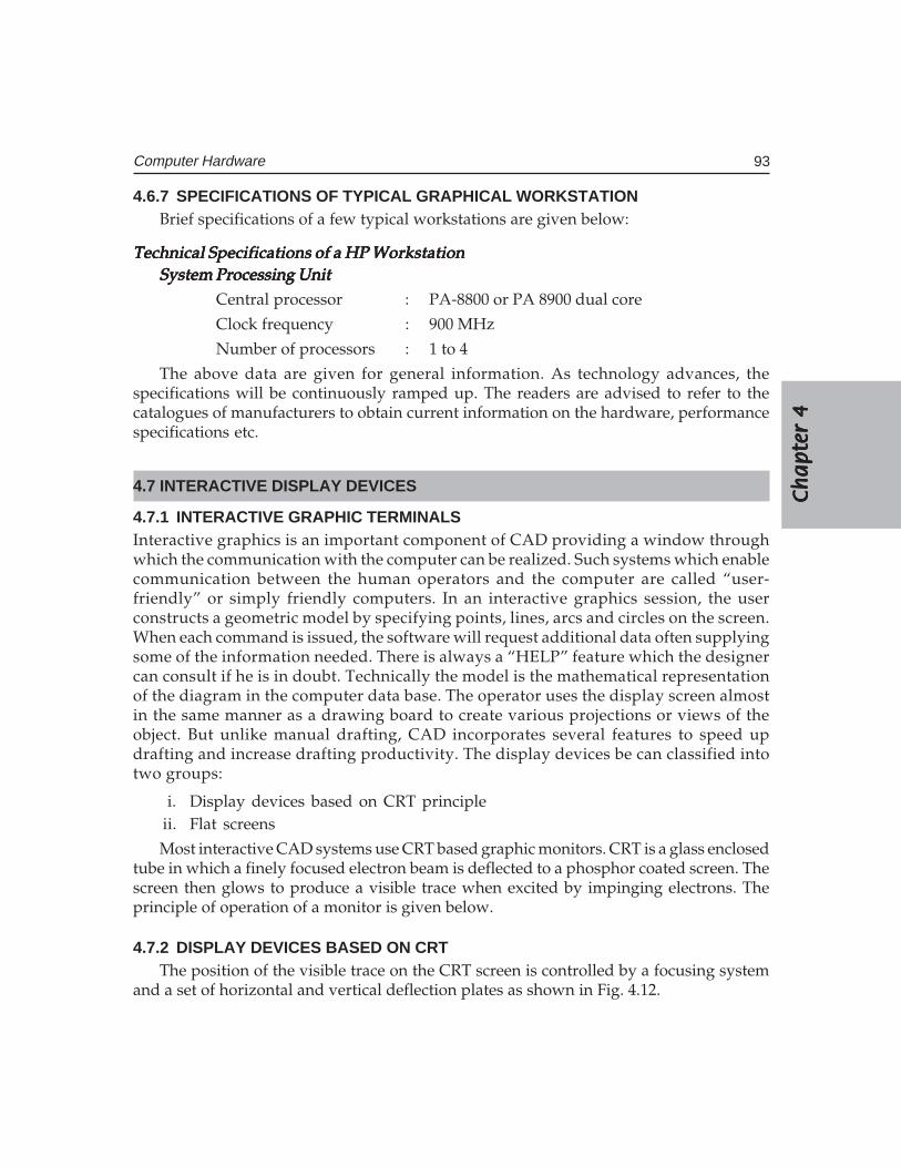
Ch
ap
ter
4C
ha
pte
r 4
Ch
ap
ter
4C
ha
pte
r 4
Ch
ap
ter
4
93Computer Hardware
4.6.7 SPECIFICATIONS OF TYPICAL GRAPHICAL WORKSTATIONBrief specifications of a few typical workstations are given below:
Technical Specifications of a HP WorkstationTechnical Specifications of a HP WorkstationTechnical Specifications of a HP WorkstationTechnical Specifications of a HP WorkstationTechnical Specifications of a HP WorkstationSystem Processing UnitSystem Processing UnitSystem Processing UnitSystem Processing UnitSystem Processing Unit
Central processor : PA-8800 or PA 8900 dual core
Clock frequency : 900 MHz
Number of processors : 1 to 4
The above data are given for general information. As technology advances, thespecifications will be continuously ramped up. The readers are advised to refer to thecatalogues of manufacturers to obtain current information on the hardware, performancespecifications etc.
4.7 INTERACTIVE DISPLAY DEVICES
4.7.1 INTERACTIVE GRAPHIC TERMINALSInteractive graphics is an important component of CAD providing a window throughwhich the communication with the computer can be realized. Such systems which enablecommunication between the human operators and the computer are called “user-friendly” or simply friendly computers. In an interactive graphics session, the userconstructs a geometric model by specifying points, lines, arcs and circles on the screen.When each command is issued, the software will request additional data often supplyingsome of the information needed. There is always a “HELP” feature which the designercan consult if he is in doubt. Technically the model is the mathematical representationof the diagram in the computer data base. The operator uses the display screen almostin the same manner as a drawing board to create various projections or views of theobject. But unlike manual drafting, CAD incorporates several features to speed updrafting and increase drafting productivity. The display devices be can classified intotwo groups:
i. Display devices based on CRT principleii. Flat screens
Most interactive CAD systems use CRT based graphic monitors. CRT is a glass enclosedtube in which a finely focused electron beam is deflected to a phosphor coated screen. Thescreen then glows to produce a visible trace when excited by impinging electrons. Theprinciple of operation of a monitor is given below.
4.7.2 DISPLAY DEVICES BASED ON CRTThe position of the visible trace on the CRT screen is controlled by a focusing system
and a set of horizontal and vertical deflection plates as shown in Fig. 4.12.
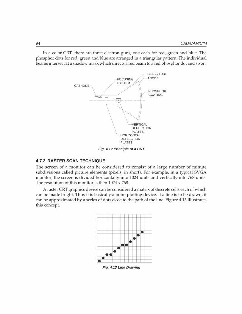
94 CAD/CAM/CIM
In a color CRT, there are three electron guns, one each for red, green and blue. Thephosphor dots for red, green and blue are arranged in a triangular pattern. The individualbeams intersect at a shadow mask which directs a red beam to a red phosphor dot and so on.
ANODE
PHOSPHORCOATING
GLASS TUBE
VERTICALDEFLECTIONPLATES
HORIZONTALDEFLECTIONPLATES
FOCUSINGSYSTEM
CATHODE
Fig. 4.12 Principle of a CRT
4.7.3 RASTER SCAN TECHNIQUEThe screen of a monitor can be considered to consist of a large number of minutesubdivisions called picture elements (pixels, in short). For example, in a typical SVGAmonitor, the screen is divided horizontally into 1024 units and vertically into 768 units.The resolution of this monitor is then 1024 x 768.
A raster CRT graphics device can be considered a matrix of discrete cells each of whichcan be made bright. Thus it is basically a point plotting device. If a line is to be drawn, itcan be approximated by a series of dots close to the path of the line. Figure 4.13 illustratesthis concept.
Fig. 4.13 Line Drawing
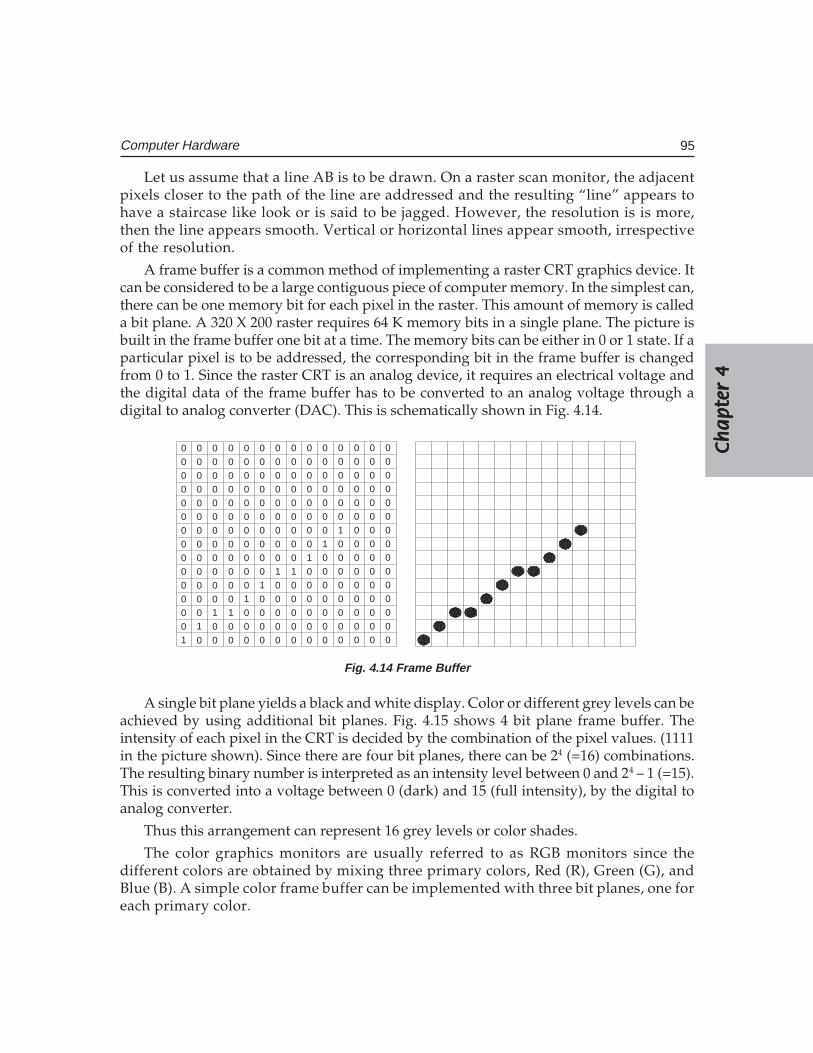
Ch
ap
ter
4C
ha
pte
r 4
Ch
ap
ter
4C
ha
pte
r 4
Ch
ap
ter
4
95Computer Hardware
Let us assume that a line AB is to be drawn. On a raster scan monitor, the adjacentpixels closer to the path of the line are addressed and the resulting “line” appears tohave a staircase like look or is said to be jagged. However, the resolution is is more,then the line appears smooth. Vertical or horizontal lines appear smooth, irrespectiveof the resolution.
A frame buffer is a common method of implementing a raster CRT graphics device. Itcan be considered to be a large contiguous piece of computer memory. In the simplest can,there can be one memory bit for each pixel in the raster. This amount of memory is calleda bit plane. A 320 X 200 raster requires 64 K memory bits in a single plane. The picture isbuilt in the frame buffer one bit at a time. The memory bits can be either in 0 or 1 state. If aparticular pixel is to be addressed, the corresponding bit in the frame buffer is changedfrom 0 to 1. Since the raster CRT is an analog device, it requires an electrical voltage andthe digital data of the frame buffer has to be converted to an analog voltage through adigital to analog converter (DAC). This is schematically shown in Fig. 4.14.
00000000000000
0
0
0000
0000
0000
0
00
000
0000
0000
0
00
000
0000
0000
0
00
00
0
0000
0000
0
00
0
00
0000
0000
0
00
000
0000
0000
0
00
000
0000
0000
00
0000
0000
0000
0
00
0000
000
0000
0
00
0000
00
0
0000
0
00
0000
0000
0000
0
00
0000
0000
0000
0
00
0000
0000
0000
11
1 11
11 1
11
1
Fig. 4.14 Frame Buffer
A single bit plane yields a black and white display. Color or different grey levels can beachieved by using additional bit planes. Fig. 4.15 shows 4 bit plane frame buffer. Theintensity of each pixel in the CRT is decided by the combination of the pixel values. (1111in the picture shown). Since there are four bit planes, there can be 24 (=16) combinations.The resulting binary number is interpreted as an intensity level between 0 and 24 – 1 (=15).This is converted into a voltage between 0 (dark) and 15 (full intensity), by the digital toanalog converter.
Thus this arrangement can represent 16 grey levels or color shades.
The color graphics monitors are usually referred to as RGB monitors since thedifferent colors are obtained by mixing three primary colors, Red (R), Green (G), andBlue (B). A simple color frame buffer can be implemented with three bit planes, one foreach primary color.
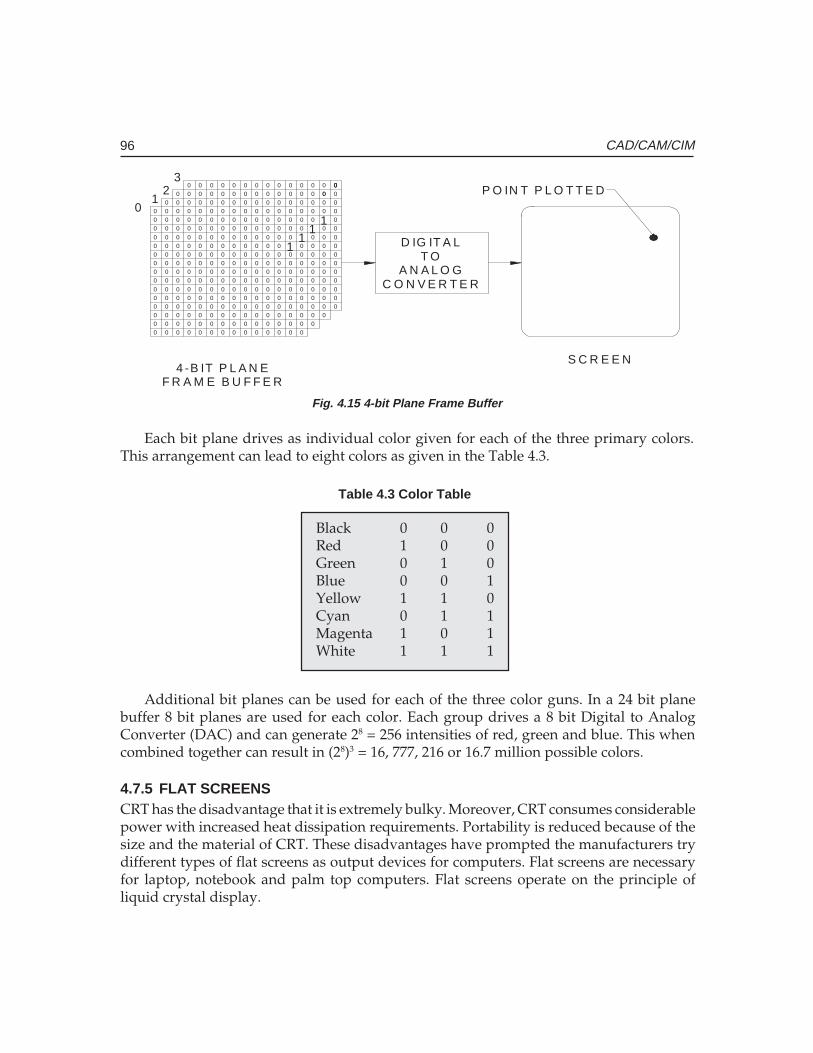
96 CAD/CAM/CIM
00000
000000
000
0
0
0000
0000
000
0
0
00
000
0000
000
0
0
00
000
0000
000
0
0
00
00
0
0000
000
0
0
00
0
00
0000
000
0
0
00
000
0000
000
0
0
00
000
0000
000
0
00
0000
0000
000
0
0
00
0000
000
000
0
0
00
0000
00
0
000
0
0
00
0000
0000
000
0
0
00
0000
000
000
0
0
00
0000
0000
000
00
0 00
00 0
00
0
00 00 0 0 00 00 0 0 0 0000 0 0 0 0 00 0 0 0 0 0
000 0 0 0 0 00 0 0 0 0 0
00
000
0
0
000
00
0
000
000
0
00
00
00
0
000
0
00
00
0
00
0
0000
D IG IT A LT O
A N A L O GC O N V E R T E R
4 -B IT P L A N EF R A M E B U F F E R
01
23
S C R E E N
11
11
P O IN T P L O T T E D
Fig. 4.15 4-bit Plane Frame Buffer
Each bit plane drives as individual color given for each of the three primary colors.This arrangement can lead to eight colors as given in the Table 4.3.
Table 4.3 Color Table
Black 0 0 0Red 1 0 0Green 0 1 0Blue 0 0 1Yellow 1 1 0Cyan 0 1 1Magenta 1 0 1White 1 1 1
Additional bit planes can be used for each of the three color guns. In a 24 bit planebuffer 8 bit planes are used for each color. Each group drives a 8 bit Digital to AnalogConverter (DAC) and can generate 28 = 256 intensities of red, green and blue. This whencombined together can result in (28)3 = 16, 777, 216 or 16.7 million possible colors.
4.7.5 FLAT SCREENSCRT has the disadvantage that it is extremely bulky. Moreover, CRT consumes considerablepower with increased heat dissipation requirements. Portability is reduced because of thesize and the material of CRT. These disadvantages have prompted the manufacturers trydifferent types of flat screens as output devices for computers. Flat screens are necessaryfor laptop, notebook and palm top computers. Flat screens operate on the principle ofliquid crystal display.
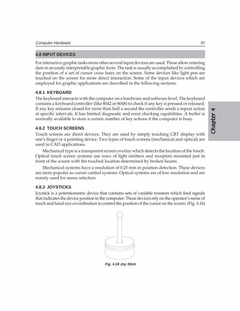
Ch
ap
ter
4C
ha
pte
r 4
Ch
ap
ter
4C
ha
pte
r 4
Ch
ap
ter
4
97Computer Hardware
4.8 INPUT DEVICES
For interactive graphic tasks more often several input devices are used. These allow enteringdata in an easily interpretable graphic form. The task is usually accomplished by controllingthe position of a set of cursor cross hairs on the screen. Some devices like light pen aretouched on the screen for more direct interaction. Some of the input devices which areemployed for graphic applications are described in the following sections.
4.8.1 KEYBOARDThe keyboard interacts with the computer on a hardware and software level. The keyboardcontains a keyboard controller (like 8042 or 8048) to check if any key is pressed or released.If any key remains closed for more than half a second the controller sends a repeat actionat specific intervals. It has limited diagnostic and error checking capabilities. A buffer isnormally available to store a certain number of key actions if the computer is busy.
4.8.2 TOUCH SCREENSTouch screens are direct devices. They are used by simply touching CRT display withone’s finger or a pointing device. Two types of touch screens (mechanical and optical) areused in CAD applications.
Mechanical type is a transparent screen overlay which detects the location of the touch.Optical touch screen systems use rows of light emitters and receptors mounted just infront of the screen with the touched location determined by broken beams.
Mechanical systems have a resolution of 0.25 mm in position detection. These devicesare more popular as cursor control systems. Optical systems are of low resolution and aremainly used for menu selection.
4.8.3 JOYSTICKSJoystick is a potentiometric device that contains sets of variable resistors which feed signalsthat indicates the device position to the computer. These devices rely on the operator’s sense oftouch and hand-eye co-ordination to control the position of the cursor on the screen. (Fig. 4.16)
Fig. 4.16 Joy Stick
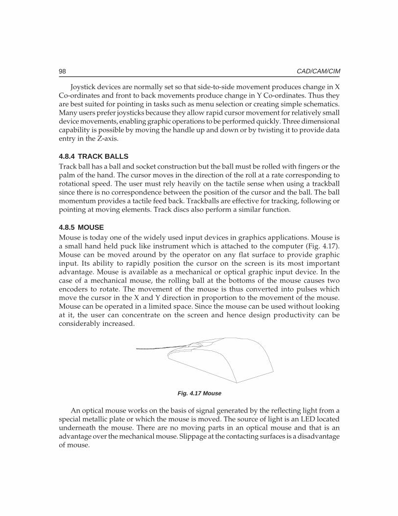
98 CAD/CAM/CIM
Joystick devices are normally set so that side-to-side movement produces change in XCo-ordinates and front to back movements produce change in Y Co-ordinates. Thus theyare best suited for pointing in tasks such as menu selection or creating simple schematics.Many users prefer joysticks because they allow rapid cursor movement for relatively smalldevice movements, enabling graphic operations to be performed quickly. Three dimensionalcapability is possible by moving the handle up and down or by twisting it to provide dataentry in the Z-axis.
4.8.4 TRACK BALLSTrack ball has a ball and socket construction but the ball must be rolled with fingers or thepalm of the hand. The cursor moves in the direction of the roll at a rate corresponding torotational speed. The user must rely heavily on the tactile sense when using a trackballsince there is no correspondence between the position of the cursor and the ball. The ballmomentum provides a tactile feed back. Trackballs are effective for tracking, following orpointing at moving elements. Track discs also perform a similar function.
4.8.5 MOUSEMouse is today one of the widely used input devices in graphics applications. Mouse isa small hand held puck like instrument which is attached to the computer (Fig. 4.17).Mouse can be moved around by the operator on any flat surface to provide graphicinput. Its ability to rapidly position the cursor on the screen is its most importantadvantage. Mouse is available as a mechanical or optical graphic input device. In thecase of a mechanical mouse, the rolling ball at the bottoms of the mouse causes twoencoders to rotate. The movement of the mouse is thus converted into pulses whichmove the cursor in the X and Y direction in proportion to the movement of the mouse.Mouse can be operated in a limited space. Since the mouse can be used without lookingat it, the user can concentrate on the screen and hence design productivity can beconsiderably increased.
Fig. 4.17 Mouse
An optical mouse works on the basis of signal generated by the reflecting light from aspecial metallic plate or which the mouse is moved. The source of light is an LED locatedunderneath the mouse. There are no moving parts in an optical mouse and that is anadvantage over the mechanical mouse. Slippage at the contacting surfaces is a disadvantageof mouse.
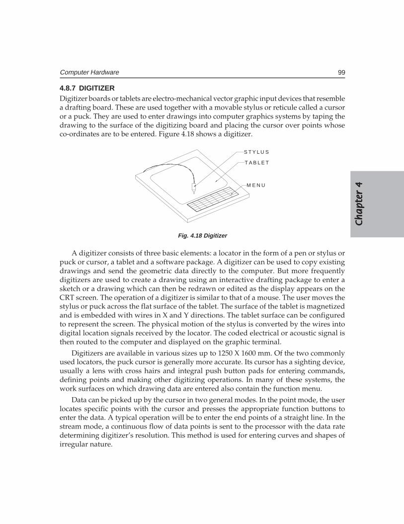
Ch
ap
ter
4C
ha
pte
r 4
Ch
ap
ter
4C
ha
pte
r 4
Ch
ap
ter
4
99Computer Hardware
4.8.7 DIGITIZERDigitizer boards or tablets are electro-mechanical vector graphic input devices that resemblea drafting board. These are used together with a movable stylus or reticule called a cursoror a puck. They are used to enter drawings into computer graphics systems by taping thedrawing to the surface of the digitizing board and placing the cursor over points whoseco-ordinates are to be entered. Figure 4.18 shows a digitizer.
T A B L E T
S T Y L U S
M E N U
Fig. 4.18 Digitizer
A digitizer consists of three basic elements: a locator in the form of a pen or stylus orpuck or cursor, a tablet and a software package. A digitizer can be used to copy existingdrawings and send the geometric data directly to the computer. But more frequentlydigitizers are used to create a drawing using an interactive drafting package to enter asketch or a drawing which can then be redrawn or edited as the display appears on theCRT screen. The operation of a digitizer is similar to that of a mouse. The user moves thestylus or puck across the flat surface of the tablet. The surface of the tablet is magnetizedand is embedded with wires in X and Y directions. The tablet surface can be configuredto represent the screen. The physical motion of the stylus is converted by the wires intodigital location signals received by the locator. The coded electrical or acoustic signal isthen routed to the computer and displayed on the graphic terminal.
Digitizers are available in various sizes up to 1250 X 1600 mm. Of the two commonlyused locators, the puck cursor is generally more accurate. Its cursor has a sighting device,usually a lens with cross hairs and integral push button pads for entering commands,defining points and making other digitizing operations. In many of these systems, thework surfaces on which drawing data are entered also contain the function menu.
Data can be picked up by the cursor in two general modes. In the point mode, the userlocates specific points with the cursor and presses the appropriate function buttons toenter the data. A typical operation will be to enter the end points of a straight line. In thestream mode, a continuous flow of data points is sent to the processor with the data ratedetermining digitizer’s resolution. This method is used for entering curves and shapes ofirregular nature.
100 CAD/CAM/CIM
Some type of digitizers can pick 3-dimensional information from a model, moving thetip of a wand along the model. These systems generate signals that are analyzed to produceco-ordinates. This type of digitizer is very useful for reverse engineering. In the case ofsonic digitizers a spark gap in the stylus tip creates a sound pulse that is detected by twostrip microphones one for X and one for Y axis. The location of the source of sound isindicated by the time it takes for the sound to reach the microphones. The sonic digitizerdoes not require a tablet.
The major sub-groups of standard digitizers are free cursor digitizers, constrained cursordigitizers and motorized cursor digitizers.
4.8.7 THUMB WHEELThumb wheels are potentiometric devices. Two of them are provided for X and Ymovements of cursor. These also have the advantage that one can look at the screen andmove the cursor.
4.8.8 AUTOMATED ENTRYOne of the major needs of design offices switching over to CAD is the necessity to convertexisting paper drawings to computer files. Many automated devices are now available forentering drawings into CAD database. These units can scan a drawing and convert theminto a form useful for CAD with little manual intervention. A typical automated drawingentry device contains a scanner and a workstation for viewing and editing the drawing.Software is required for rasterizing and vectorizing the scanned drawings.
Most systems begin the data entry process by scanning a document to create a rasterimage. A scanning rate of 13 dots/mm is adequate for most engineering applications. Thepixel data may be stored or manipulated by converting it into vectors with the aid ofsophisticated software. At the work station vectors are organized into graphic primitivessuch as line, arcs, circles, etc. symbols and text may also be recognized by the system and areconverted into a single piece of data. Many systems can even recognize handwritten lettering.
Recently artificial intelligence techniques similar to those employed in robot visiontechnology have been used for automatic entry of drawing into the computer. Texts areusually entered in separate layers to enable easy revision.
4.9 OUTPUT DEVICES
A CAD system is not complete unless it can make hard copies of designs or analysis createdon the computer. Determining the best output device for a typical CIM application is athree-step process: specifying how hard copies will be used, identifying quality and costcriteria and selecting equipment most suitable for the application.
Hard copies are used for a variety of purposes, including shop use, file storage, reportsand presentations. Design iterations can be reduced by making hard copies at crucial stagesand distributing them to key personnel for review. Documents and drawings are required
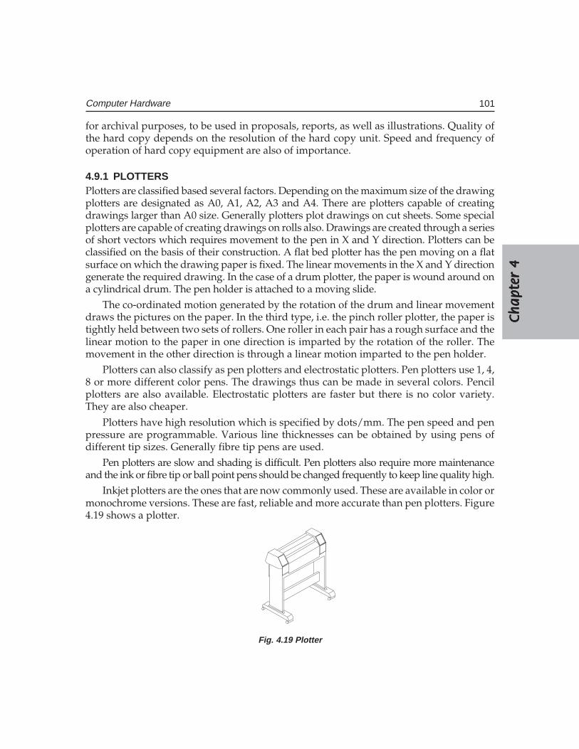
Ch
ap
ter
4C
ha
pte
r 4
Ch
ap
ter
4C
ha
pte
r 4
Ch
ap
ter
4
101Computer Hardware
for archival purposes, to be used in proposals, reports, as well as illustrations. Quality ofthe hard copy depends on the resolution of the hard copy unit. Speed and frequency ofoperation of hard copy equipment are also of importance.
4.9.1 PLOTTERSPlotters are classified based several factors. Depending on the maximum size of the drawingplotters are designated as A0, A1, A2, A3 and A4. There are plotters capable of creatingdrawings larger than A0 size. Generally plotters plot drawings on cut sheets. Some specialplotters are capable of creating drawings on rolls also. Drawings are created through a seriesof short vectors which requires movement to the pen in X and Y direction. Plotters can beclassified on the basis of their construction. A flat bed plotter has the pen moving on a flatsurface on which the drawing paper is fixed. The linear movements in the X and Y directiongenerate the required drawing. In the case of a drum plotter, the paper is wound around ona cylindrical drum. The pen holder is attached to a moving slide.
The co-ordinated motion generated by the rotation of the drum and linear movementdraws the pictures on the paper. In the third type, i.e. the pinch roller plotter, the paper istightly held between two sets of rollers. One roller in each pair has a rough surface and thelinear motion to the paper in one direction is imparted by the rotation of the roller. Themovement in the other direction is through a linear motion imparted to the pen holder.
Plotters can also classify as pen plotters and electrostatic plotters. Pen plotters use 1, 4,8 or more different color pens. The drawings thus can be made in several colors. Pencilplotters are also available. Electrostatic plotters are faster but there is no color variety.They are also cheaper.
Plotters have high resolution which is specified by dots/mm. The pen speed and penpressure are programmable. Various line thicknesses can be obtained by using pens ofdifferent tip sizes. Generally fibre tip pens are used.
Pen plotters are slow and shading is difficult. Pen plotters also require more maintenanceand the ink or fibre tip or ball point pens should be changed frequently to keep line quality high.
Inkjet plotters are the ones that are now commonly used. These are available in color ormonochrome versions. These are fast, reliable and more accurate than pen plotters. Figure4.19 shows a plotter.
Fig. 4.19 Plotter

102 CAD/CAM/CIM
4.9.2 PRINTERS
Several types of printers are available:Several types of printers are available:Several types of printers are available:Several types of printers are available:Several types of printers are available:
(i) Impact printers: Impact printers: Impact printers: Impact printers: Impact printers: They use small hammers or print heads containing small pinsto strike a ribbon to form dot matrix images. Colors are introduced through theuse of multiple ribbons or single ribbons with different color bands. Color intensityis fixed and creating shades is almost impossible. Because of the low resolution,copy quality is poor. Impact printers are suitable for high speed, low cost, highvolume hard copies.
(ii) Inkjet printer:Inkjet printer:Inkjet printer:Inkjet printer:Inkjet printer: Inkjet printers produce images by propelling fine droplets of inkon to the medium to be printed. Droplets can be generated in continuous streamsor pulses. Some of the droplets get charged and are returned to the reservoir,while uncharged droplets attach to the printing surface to form graphics. Thelaser jet printers are capable of giving good quality color prints with shading atreasonable cost.
(iii) Laser Laser Laser Laser Laser ppppprinter:rinter:rinter:rinter:rinter: Laser printer is one of the most widely used output devices. This typecombines high speed with high resolution and the quality of output is very fine.
QUESTIONS
1. Describe the principal features and list the major specifications of a personalcomputer.
2. Sketch and describe the layout of the mother board of a Pentium PC.3. How does a mainframe computer differ from a PC?4. What are the output interfaces available on a PC? How do they differ from each
other?5. Describe the advantages of a local area network in a design environment?6. What are the salient features of a UNIX based design workstation?7. What are the principal subsystems of a graphics engine?8. List the major specifications of a design workstation.9. Describe the principle of working of a CRT.
10. How is a line displayed on a graphics monitor?11. What is the function of a frame buffer?12. What is the advantage of a mouse as an input device?13. Compare the relative merits and demerits of different input devices.14. What is the important output devices used in CAD?
�������������� �
���������� ����
�������
Operating systems represent very significant class of software essential for the operationof a computer. The Application software must be compatible with the operating system.Different operating systems are used in computers. This chapter gives a brief overview ofpopular operating systems like UNIX, Windows and Linux.
5.1 INTRODUCTION
Software that is of interest to CAD/CAM/CIM Engineers falls under different categories.They are:
i. Operating Systemsii. Application Software for
a. Geometric modelingb. Design and analysis of components and systemsc. Finite elements analysisd. Mechanism analysise. Other design applicationsf. CNC programmingg. Process planningh. Tool Designi. Inspectionj. ERP
General aspects of operating system software are discussed in this chapter. A sectionon files and file handling is included to familiarize the reader in one of the importantstages in program development. Since separate chapters on application software for designand analysis are included, they are not discussed in this chapter. Details of geometricmodeling software are dealt with at length in several chapters.
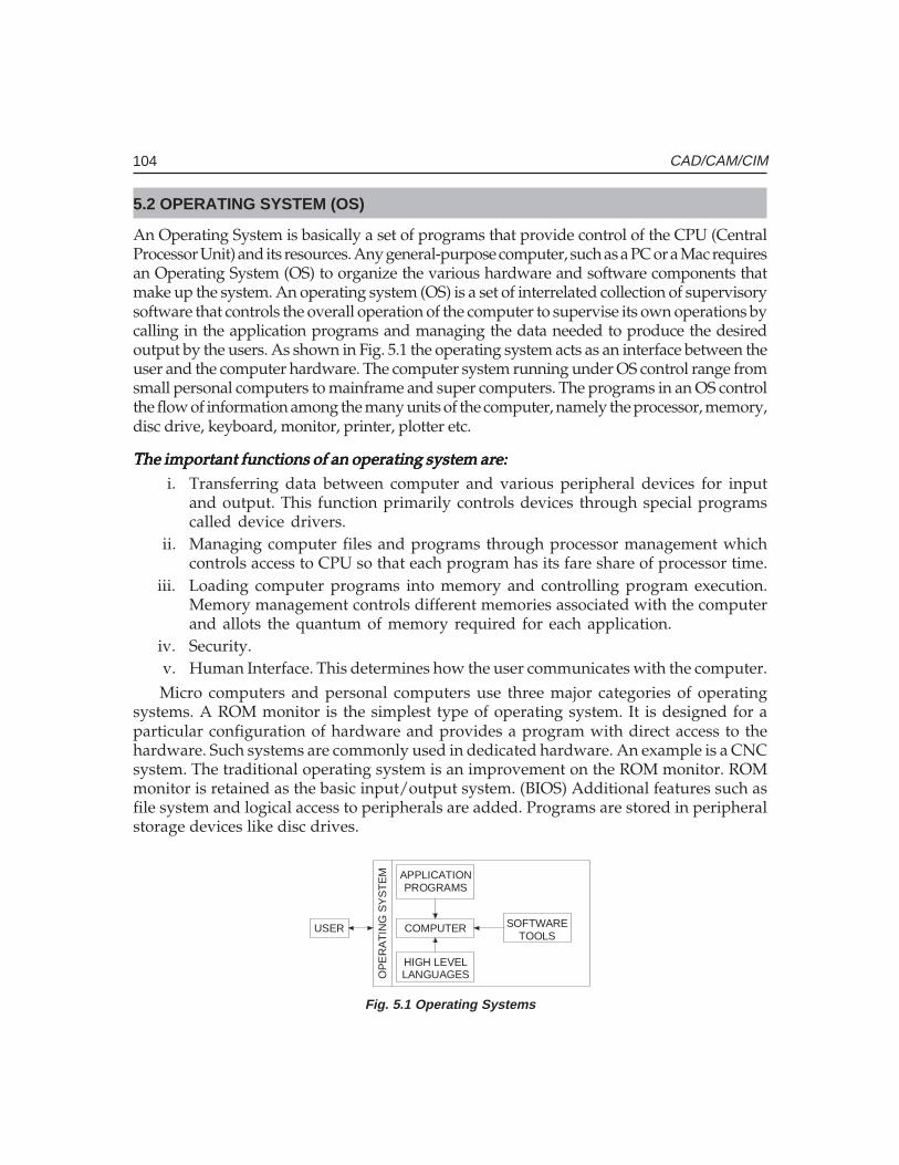
104 CAD/CAM/CIM
5.2 OPERATING SYSTEM (OS)
An Operating System is basically a set of programs that provide control of the CPU (CentralProcessor Unit) and its resources. Any general-purpose computer, such as a PC or a Mac requiresan Operating System (OS) to organize the various hardware and software components thatmake up the system. An operating system (OS) is a set of interrelated collection of supervisorysoftware that controls the overall operation of the computer to supervise its own operations bycalling in the application programs and managing the data needed to produce the desiredoutput by the users. As shown in Fig. 5.1 the operating system acts as an interface between theuser and the computer hardware. The computer system running under OS control range fromsmall personal computers to mainframe and super computers. The programs in an OS controlthe flow of information among the many units of the computer, namely the processor, memory,disc drive, keyboard, monitor, printer, plotter etc.
The important functions of an operating system are:The important functions of an operating system are:The important functions of an operating system are:The important functions of an operating system are:The important functions of an operating system are:i. Transferring data between computer and various peripheral devices for input
and output. This function primarily controls devices through special programscalled device drivers.
ii. Managing computer files and programs through processor management whichcontrols access to CPU so that each program has its fare share of processor time.
iii. Loading computer programs into memory and controlling program execution.Memory management controls different memories associated with the computerand allots the quantum of memory required for each application.
iv. Security.v. Human Interface. This determines how the user communicates with the computer.Micro computers and personal computers use three major categories of operating
systems. A ROM monitor is the simplest type of operating system. It is designed for aparticular configuration of hardware and provides a program with direct access to thehardware. Such systems are commonly used in dedicated hardware. An example is a CNCsystem. The traditional operating system is an improvement on the ROM monitor. ROMmonitor is retained as the basic input/output system. (BIOS) Additional features such asfile system and logical access to peripherals are added. Programs are stored in peripheralstorage devices like disc drives.
USERTOOLS
SOFTWARE
LANGUAGESHIGH LEVEL
COMPUTER
PROGRAMSAPPLICATION
OP
ER
AT
ING
SY
ST
EM
Fig. 5.1 Operating Systems
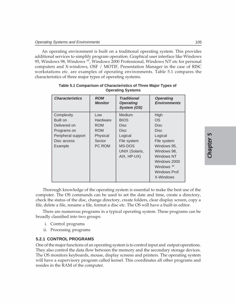
Ch
ap
ter
5C
ha
pte
r 5
Ch
ap
ter
5C
ha
pte
r 5
Ch
ap
ter
5
105Operating Systems and Environments
An operating environment is built on a traditional operating system. This providesadditional services to simplify program operation. Graphical user interface like Windows95, Windows 98, Windows XP, Windows 2000 Professional, Windows NT etc for personalcomputers and X-windows, OSF / MOTIF, Presentation Manager in the case of RISCworkstations etc. are examples of operating environments. Table 5.1 compares thecharacteristics of three major types of operating systems.
Thorough knowledge of the operating system is essential to make the best use of thecomputer. The OS commands can be used to set the date and time, create a directory,check the status of the disc, change directory, create folders, clear display screen, copy afile, delete a file, rename a file, format a disc etc. The OS will have a built-in editor.
There are numerous programs in a typical operating system. These programs can bebroadly classified into two groups:
i. Control programsii. Processing programs
5.2.1 CONTROL PROGRAMSOne of the major functions of an operating system is to control input and output operations.They also control the data flow between the memory and the secondary storage devices.The OS monitors keyboards, mouse, display screens and printers. The operating systemwill have a supervisory program called kernel. This coordinates all other programs andresides in the RAM of the computer.
Table 5.1 Comparison of Characteristics of Three Major Types ofOperating Systems
Characteristics ROM Traditional OperatingMonitor Operating Environments
System (OS)
Complexity Low Medium HighBuilt on Hardware BIOS OSDelivered on ROM Disc DiscPrograms on ROM Disc DiscPeripheral support Physical Logical LogicalDisc access Sector File system File systemExample PC ROM MS-DOS Windows 95,
UNIX (Solaris, Windows 98,AIX, HP-UX) Windows NT
Windows 2000Windows XP
Windows Prof.X-Windows
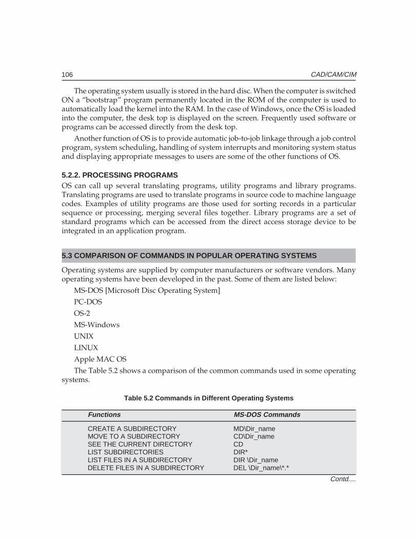
106 CAD/CAM/CIM
The operating system usually is stored in the hard disc. When the computer is switchedON a “bootstrap” program permanently located in the ROM of the computer is used toautomatically load the kernel into the RAM. In the case of Windows, once the OS is loadedinto the computer, the desk top is displayed on the screen. Frequently used software orprograms can be accessed directly from the desk top.
Another function of OS is to provide automatic job-to-job linkage through a job controlprogram, system scheduling, handling of system interrupts and monitoring system statusand displaying appropriate messages to users are some of the other functions of OS.
5.2.2. PROCESSING PROGRAMSOS can call up several translating programs, utility programs and library programs.Translating programs are used to translate programs in source code to machine languagecodes. Examples of utility programs are those used for sorting records in a particularsequence or processing, merging several files together. Library programs are a set ofstandard programs which can be accessed from the direct access storage device to beintegrated in an application program.
5.3 COMPARISON OF COMMANDS IN POPULAR OPERATING SYSTEMS
Operating systems are supplied by computer manufacturers or software vendors. Manyoperating systems have been developed in the past. Some of them are listed below:
MS-DOS [Microsoft Disc Operating System]
PC-DOS
OS-2
MS-Windows
UNIX
LINUX
Apple MAC OS
The Table 5.2 shows a comparison of the common commands used in some operatingsystems.
Table 5.2 Commands in Different Operating Systems
Functions MS-DOS Commands
CREATE A SUBDIRECTORY MD\Dir_nameMOVE TO A SUBDIRECTORY CD\Dir_nameSEE THE CURRENT DIRECTORY CDLIST SUBDIRECTORIES DIR*LIST FILES IN A SUBDIRECTORY DIR \Dir_nameDELETE FILES IN A SUBDIRECTORY DEL \Dir_name\*.*
Contd....

Ch
ap
ter
5C
ha
pte
r 5
Ch
ap
ter
5C
ha
pte
r 5
Ch
ap
ter
5
107Operating Systems and Environments
Functions MS-DOS Commands
DELETE A SUBDIRECTORY RD \Dir_nameLIST FILES OF SAME EXTENSION Dir *.ExtLIST FILES, FILENAME STARTING WITH X DIR X*.*COPY FILE FROM HARDDISC TO FLOPPY COPY C:Filename.Ext A:CREATE A FILE EDLIN Filename.ExtEDIT A FILE EDLIN Filename.ExtDISPLAY FILE CONTENTS TYPE Filename.ExtPRINT A FILE PRINT Filename.ExtSORT FILES IN A SUBDIRECTORY DIR \Dir_name | SORTRENAME A FILE REN Oldname.Ext Newname.ExtAPPEND ONE FILE TO OTHER COPY File1.Ext+File2.Ext
Newname.ExtSEARCH A STRING IN A FILE SFIND “String” Filename.ExtCHANGE ATTRIBUTE OF A FILE
(Read only) ATTRIB +R Filename.Ext(Read/Write) ATTRIB -R Filename.Ext
CREATE A SUBDIRECTORY mkdir Dir_nameMOVE TO A SUBDIRECTORY cd \Dir_nameSEE THE CURRENT DIRECTORY pwdLIST FILES IN A SUBDIRECTORY ls Dir_nameDELETE FILES IN A SUBDIRECTORY rm Dir_name/?*.*DELETE A SUBDIRECTORY rm Dir_nameLIST FILES OF SAME EXTENSION ls *.ExtLIST FILES, FILENAME STARTING WITH X ls X*.*COPY FILES FROM ONE cp source_Dir/Filename.Ext Dest_DirSUBDIRECTORY TO ANOTHER mv Source_Dir/Filename.Ext Dest_DirMOVE FILE FROM ONE
SUBDIRECTORY TO ANOTHER tar -xvb device-nameCOPY FILES FROM CATRIDGE TAPE
TO HARD DISCCOPY FILES FROM HARDDISC tar -cvb device-name
TO CATRIDGE TAPECREATE A FILE vi Filename.ExtEDIT A FILE vi Filename.ExtDISPLAY FILE CONTENTS cat Filename.ExtPRINT A FILE lp Filename.ExtRENAME A FILE mv Source.Ext Newname.ExtAPPEND ONE FILE TO OTHER cp Firstfile.Ext+Secondfile.Ext NewfileCREATE LINK TO A FILE IN A ln Link-name File_path
SUBDIRECTORYSEARCH A STRING IN A FILE grep String Filename.Ext
Contd....
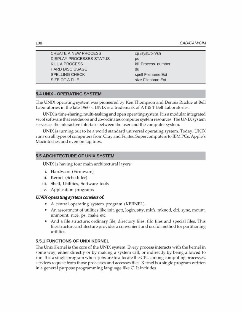
108 CAD/CAM/CIM
CREATE A NEW PROCESS cp /sys5/bin/shDISPLAY PROCESSES STATUS psKILL A PROCESS kill Process_numberHARD DISC USAGE duSPELLING CHECK spell Filename.ExtSIZE OF A FILE size Filename.Ext
5.4 UNIX - OPERATING SYSTEM
The UNIX operating system was pioneered by Ken Thompson and Dennis Ritchie at BellLaboratories in the late 1960’s. UNIX is a trademark of AT & T Bell Laboratories.
UNIX is time-sharing, multi-tasking and open operating system. It is a modular integratedset of software that resides on and co-ordinates computer system resources. The UNIX systemserves as the interactive interface between the user and the computer system.
UNIX is turning out to be a world standard universal operating system. Today, UNIXruns on all types of computers from Cray and Fujitsu Supercomputers to IBM PCs, Apple’sMacintoshes and even on lap tops.
5.5 ARCHITECTURE OF UNIX SYSTEM
UNIX is having four main architectural layers:
i. Hardware (Firmware)ii. Kernel (Scheduler)
iii. Shell, Utilities, Software toolsiv. Application programs
UNIX operating system consists of:UNIX operating system consists of:UNIX operating system consists of:UNIX operating system consists of:UNIX operating system consists of:
• A central operating system program (KERNEL).• An assortment of utilities like init, gett, login, stty, mkfs, mknod, clri, sync, mount,
unmount, nice, ps, make etc.• And a file structure; ordinary file, directory files, fifo files and special files. This
file structure architecture provides a convenient and useful method for partitioningutilities.
5.5.1 FUNCTIONS OF UNIX KERNELThe Unix Kernel is the core of the UNIX system. Every process interacts with the kernel insome way, either directly or by making a system call, or indirectly by being allowed torun. It is a single program whose jobs are to allocate the CPU among computing processes,services request from those processes and accesses files. Kernel is a single program writtenin a general purpose programming language like C. It includes
Ch
ap
ter
5C
ha
pte
r 5
Ch
ap
ter
5C
ha
pte
r 5
Ch
ap
ter
5
109Operating Systems and Environments
• Interrupt and error handling• System accounting• Memory management• Process scheduling and management• Input/Output services• File management and security• Date and time services
5.5.2 FUNCTIONS OF THE SHELLIn AT & T’s version the Bourne shell prompt is ‘$’ and Berkeley’s BSD shell prompt is ‘%’.The shell is an interpreter program which acts for:
• Program execution• Interactive programming language• Pipe-line hookup• Input/Output redirection• Filename substitution
5.5.3 REASONS FOR THE POPULARITY OF UNIXThe popularity of UNIX can be attributed to many of its very distinctive features. Some ofthem are listed below.
• A general purpose system for performing a wide variety of jobs orapplications.
• An interactive environment that allows you to communicate directly withthe computer and receive immediate responses to your requests andmessages.
• A multi-user environment that allows you to share the computer’s resourceswith other users without sacrificing productivity.
• The system’s main asset is its portability, the relative ease with which itcan be implemented on different hardware, software systems andarchitectures.
• UNIX has achieved the status of a de-facto standard in the computerindustries.
• Net-working in enterprise wide client-server computing.• UNIX has found a home on workstations. It matches up naturally with
Reduced Instruction Set Computing (RISC) workstations.• Distributed processing capability, satellite, and fully transparent distributed
system.• POSIX - Portable Operating System Interface,
110 CAD/CAM/CIM
• Shell programming• Sophisticated security for user, group, others and file, record locking with
encode decode facility.• UNIX supports almost all programming languages.• UNIX offers many “vertical” applications such as financial modeling,
robotics and medical billing.Because of the availability and wide acceptability of UNIX, hundreds of software tools
and utilities have been developed with the help of which a programmer can save his timeand can utilize it for better software development for the effective use of computer.
UNIX serves all levels of users:UNIX serves all levels of users:UNIX serves all levels of users:UNIX serves all levels of users:UNIX serves all levels of users:Office automation - Text processing, text formatting.Terminal operator - Online transaction processing (OLTP).Programmer - Plenty of utilities are available to reduce
miscellaneous programming.Engineers - Work stations (CAD, CAM, CASE, and Robotics).Managers - Shell programming for query purpose, mail
processing for decision making.Multi-unit industry - By using extensive networking communication
facilities.
5.5.4 BASIC UNIX SYSTEM COMMANDS
at:at:at:at:at: Request that a command be run in background mode at a time you specifyon the command line. If you do not specify a time, at (1) displays the jobnumbers of all jobs you have running in at (1), batch (1), or background mode.
A sample format is:at 8:45am Jun 09 <CR>command1<CR> command2<CR><^d>
If you use the at command without the date, the command executes within 24 hours atthe time specified.
banner:banner:banner:banner:banner: Display a message (in words one to ten characters long) in large letter on thestandard output.
batch:batch:batch:batch:batch: Submit command(s) to be processed when the system load is at an acceptablelevel. A sample format of this command is:batch<CR>command1<CR>command2<CR><^d>
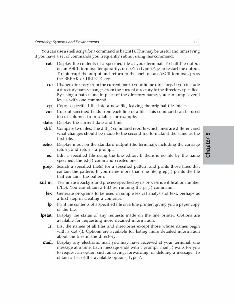
Ch
ap
ter
5C
ha
pte
r 5
Ch
ap
ter
5C
ha
pte
r 5
Ch
ap
ter
5
111Operating Systems and Environments
You can use a shell script for a command in batch(1). This may be useful and timesavingif you have a set of commands you frequently submit using this command.
cat:cat:cat:cat:cat: Display the contents of a specified file at your terminal. To halt the outputon an ASCII terminal temporarily, use <^s>; type <^q> to restart the output.To interrupt the output and return to the shell on an ASCII terminal, pressthe BREAK or DELETE key.
cd:cd:cd:cd:cd: Change directory from the current one to your home directory. If you includea directory name, changes from the current directory to the directory specified.By using a path name in place of the directory name, you can jump severallevels with one command.
cpcpcpcpcp: Copy a specified file into a new file, leaving the original file intact.cutcutcutcutcut: Cut out specified fields from each line of a file. This command can be used
to cut columns from a table, for example.date:date:date:date:date: Display the current date and time.diffdiffdiffdiffdiff: Compare two files. The diff(1) command reports which lines are different and
what changes should be made to the second file to make it the same as thefirst file.
echoechoechoechoecho: Display input on the standard output (the terminal), including the carriagereturn, and returns a prompt.
ededededed: Edit a specified file using the line editor. If there is no file by the namespecified, the ed(1) command creates one.
grepgrepgrepgrepgrep: Search a specified file(s) for a specified pattern and prints those lines thatcontain the pattern. If you name more than one file, grep(1) prints the filethat contains the pattern.
kill m:kill m:kill m:kill m:kill m: Terminate a background process specified by its process identification number(PID). You can obtain a PID by running the ps(1) command.
lexlexlexlexlex: Generate programs to be used in simple lexical analysis of text, perhaps asa first step in creating a compiler.
lplplplplp: Print the contents of a specified file on a line printer, giving you a paper copyof the file.
lpstat:lpstat:lpstat:lpstat:lpstat: Display the status of any requests made on the line printer. Options areavailable for requesting more detailed information.
ls:ls:ls:ls:ls: List the names of all files and directories except those whose names beginwith a dot (.). Options are available for listing more detailed informationabout the files in the directory.
mail:mail:mail:mail:mail: Display any electronic mail you may have received at your terminal, onemessage at a time. Each message ends with ? prompt’ mail(1) waits for youto request an option such as saving, forwarding, or deleting a message. Toobtain a list of the available options, type ?.
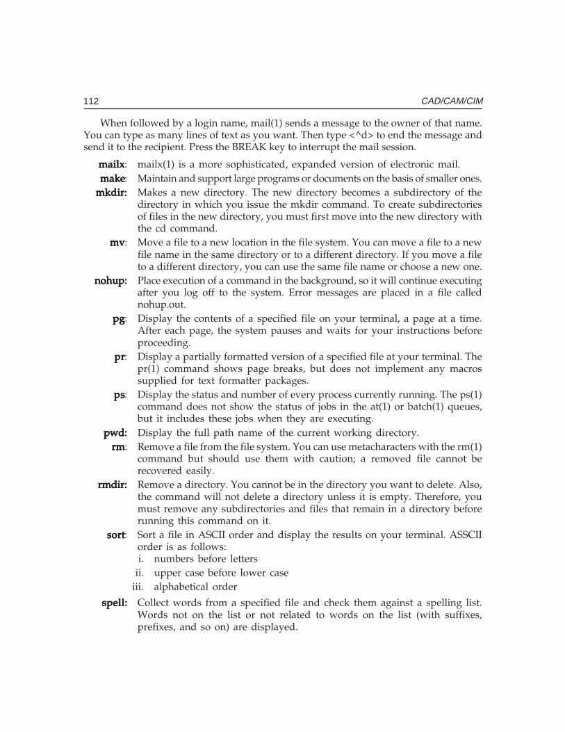
112 CAD/CAM/CIM
When followed by a login name, mail(1) sends a message to the owner of that name.You can type as many lines of text as you want. Then type <^d> to end the message andsend it to the recipient. Press the BREAK key to interrupt the mail session.
mailxmailxmailxmailxmailx: mailx(1) is a more sophisticated, expanded version of electronic mail.makemakemakemakemake: Maintain and support large programs or documents on the basis of smaller ones.
mkdir:mkdir:mkdir:mkdir:mkdir: Makes a new directory. The new directory becomes a subdirectory of thedirectory in which you issue the mkdir command. To create subdirectoriesof files in the new directory, you must first move into the new directory withthe cd command.
mvmvmvmvmv: Move a file to a new location in the file system. You can move a file to a newfile name in the same directory or to a different directory. If you move a fileto a different directory, you can use the same file name or choose a new one.
nohup:nohup:nohup:nohup:nohup: Place execution of a command in the background, so it will continue executingafter you log off to the system. Error messages are placed in a file callednohup.out.
pgpgpgpgpg: Display the contents of a specified file on your terminal, a page at a time.After each page, the system pauses and waits for your instructions beforeproceeding.
prprprprpr: Display a partially formatted version of a specified file at your terminal. Thepr(1) command shows page breaks, but does not implement any macrossupplied for text formatter packages.
pspspspsps: Display the status and number of every process currently running. The ps(1)command does not show the status of jobs in the at(1) or batch(1) queues,but it includes these jobs when they are executing.
pwd:pwd:pwd:pwd:pwd: Display the full path name of the current working directory.rmrmrmrmrm: Remove a file from the file system. You can use metacharacters with the rm(1)
command but should use them with caution; a removed file cannot berecovered easily.
rmdir:rmdir:rmdir:rmdir:rmdir: Remove a directory. You cannot be in the directory you want to delete. Also,the command will not delete a directory unless it is empty. Therefore, youmust remove any subdirectories and files that remain in a directory beforerunning this command on it.
sortsortsortsortsort: Sort a file in ASCII order and display the results on your terminal. ASSCIIorder is as follows:i. numbers before letters
ii. upper case before lower caseiii. alphabetical order
spell:spell:spell:spell:spell: Collect words from a specified file and check them against a spelling list.Words not on the list or not related to words on the list (with suffixes,prefixes, and so on) are displayed.
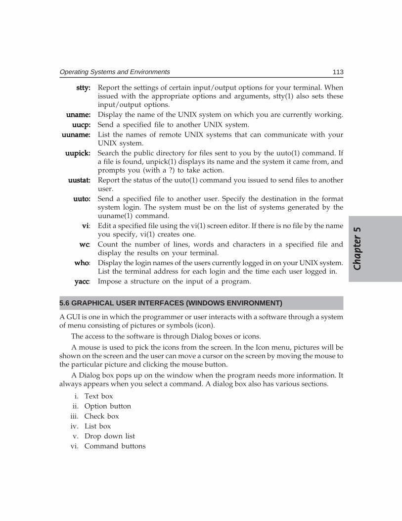
Ch
ap
ter
5C
ha
pte
r 5
Ch
ap
ter
5C
ha
pte
r 5
Ch
ap
ter
5
113Operating Systems and Environments
stty:stty:stty:stty:stty: Report the settings of certain input/output options for your terminal. Whenissued with the appropriate options and arguments, stty(1) also sets theseinput/output options.
uname:uname:uname:uname:uname: Display the name of the UNIX system on which you are currently working.uucp:uucp:uucp:uucp:uucp: Send a specified file to another UNIX system.
uuname:uuname:uuname:uuname:uuname: List the names of remote UNIX systems that can communicate with yourUNIX system.
uupick:uupick:uupick:uupick:uupick: Search the public directory for files sent to you by the uuto(1) command. Ifa file is found, unpick(1) displays its name and the system it came from, andprompts you (with a ?) to take action.
uustat:uustat:uustat:uustat:uustat: Report the status of the uuto(1) command you issued to send files to anotheruser.
uuto:uuto:uuto:uuto:uuto: Send a specified file to another user. Specify the destination in the formatsystem login. The system must be on the list of systems generated by theuuname(1) command.
vivivivivi: Edit a specified file using the vi(1) screen editor. If there is no file by the nameyou specify, vi(1) creates one.
wcwcwcwcwc: Count the number of lines, words and characters in a specified file anddisplay the results on your terminal.
whowhowhowhowho: Display the login names of the users currently logged in on your UNIX system.List the terminal address for each login and the time each user logged in.
yaccyaccyaccyaccyacc: Impose a structure on the input of a program.
5.6 GRAPHICAL USER INTERFACES (WINDOWS ENVIRONMENT)
A GUI is one in which the programmer or user interacts with a software through a systemof menu consisting of pictures or symbols (icon).
The access to the software is through Dialog boxes or icons.
A mouse is used to pick the icons from the screen. In the Icon menu, pictures will beshown on the screen and the user can move a cursor on the screen by moving the mouse tothe particular picture and clicking the mouse button.
A Dialog box pops up on the window when the program needs more information. Italways appears when you select a command. A dialog box also has various sections.
i. Text boxii. Option button
iii. Check boxiv. List boxv. Drop down list
vi. Command buttons
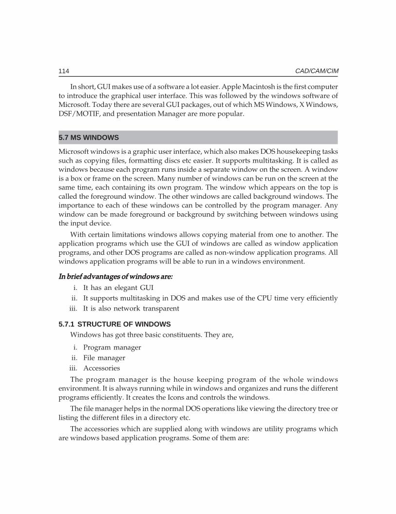
114 CAD/CAM/CIM
In short, GUI makes use of a software a lot easier. Apple Macintosh is the first computerto introduce the graphical user interface. This was followed by the windows software ofMicrosoft. Today there are several GUI packages, out of which MS Windows, X Windows,DSF/MOTIF, and presentation Manager are more popular.
5.7 MS WINDOWS
Microsoft windows is a graphic user interface, which also makes DOS housekeeping taskssuch as copying files, formatting discs etc easier. It supports multitasking. It is called aswindows because each program runs inside a separate window on the screen. A windowis a box or frame on the screen. Many number of windows can be run on the screen at thesame time, each containing its own program. The window which appears on the top iscalled the foreground window. The other windows are called background windows. Theimportance to each of these windows can be controlled by the program manager. Anywindow can be made foreground or background by switching between windows usingthe input device.
With certain limitations windows allows copying material from one to another. Theapplication programs which use the GUI of windows are called as window applicationprograms, and other DOS programs are called as non-window application programs. Allwindows application programs will be able to run in a windows environment.
In brief advantages of windows are:In brief advantages of windows are:In brief advantages of windows are:In brief advantages of windows are:In brief advantages of windows are:
i. It has an elegant GUIii. It supports multitasking in DOS and makes use of the CPU time very efficiently
iii. It is also network transparent
5.7.1 STRUCTURE OF WINDOWSWindows has got three basic constituents. They are,
i. Program managerii. File manager
iii. Accessories
The program manager is the house keeping program of the whole windowsenvironment. It is always running while in windows and organizes and runs the differentprograms efficiently. It creates the Icons and controls the windows.
The file manager helps in the normal DOS operations like viewing the directory tree orlisting the different files in a directory etc.
The accessories which are supplied along with windows are utility programs whichare windows based application programs. Some of them are:
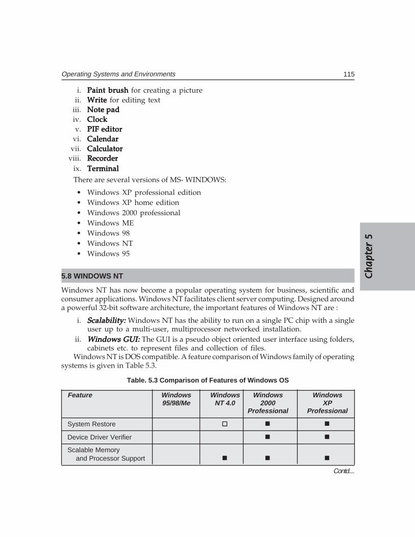
Ch
ap
ter
5C
ha
pte
r 5
Ch
ap
ter
5C
ha
pte
r 5
Ch
ap
ter
5
115Operating Systems and Environments
i. Paint brushPaint brushPaint brushPaint brushPaint brush for creating a pictureii. WriteWriteWriteWriteWrite for editing text
iii. Note padNote padNote padNote padNote padiv. ClockClockClockClockClockv. PIF editorPIF editorPIF editorPIF editorPIF editor
vi. CalendarCalendarCalendarCalendarCalendarvii. CalculatorCalculatorCalculatorCalculatorCalculator
viii. RecorderRecorderRecorderRecorderRecorderix. TerminalTerminalTerminalTerminalTerminalThere are several versions of MS- WINDOWS:
• Windows XP professional edition• Windows XP home edition• Windows 2000 professional• Windows ME• Windows 98• Windows NT• Windows 95
5.8 WINDOWS NT
Windows NT has now become a popular operating system for business, scientific andconsumer applications. Windows NT facilitates client server computing. Designed arounda powerful 32-bit software architecture, the important features of Windows NT are :
i. Scalability: Scalability: Scalability: Scalability: Scalability: Windows NT has the ability to run on a single PC chip with a singleuser up to a multi-user, multiprocessor networked installation.
ii. Windows GUI: Windows GUI: Windows GUI: Windows GUI: Windows GUI: The GUI is a pseudo object oriented user interface using folders,cabinets etc. to represent files and collection of files.
Windows NT is DOS compatible. A feature comparison of Windows family of operatingsystems is given in Table 5.3.
Table. 5.3 Comparison of Features of Windows OS
Feature Windows Windows Windows Windows95/98/Me NT 4.0 2000 XP
Professional Professional
System Restore � � �
Device Driver Verifier � �
Scalable Memoryand Processor Support � � �
Contd....
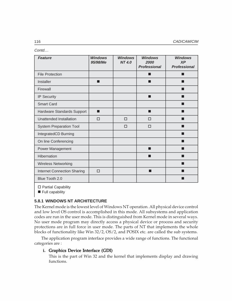
116 CAD/CAM/CIM
Feature Windows Windows Windows Windows95/98/Me NT 4.0 2000 XP
Professional Professional
File Protection � �
Installer � � �
Firewall �
IP Security � �
Smart Card �
Hardware Standards Support � � �
Unattended Installation � � � �
System Preparation Tool � � �
IntegratedCD Burning �
On line Conferencing �
Power Management � �
Hibernation � �
Wireless Networking �
Internet Connection Sharing � � �
Blue Tooth 2.0 �
� Partial Capability� Full capability
5.8.1 WINDOWS NT ARCHITECTUREThe Kernel mode is the lowest level of Windows NT operation. All physical device controland low level OS control is accomplished in this mode. All subsystems and applicationcodes are run in the user mode. This is distinguished from Kernel mode in several ways.No user mode program may directly access a physical device or process and securityprotections are in full force in user mode. The parts of NT that implements the wholeblocks of functionality like Win 32/2, OS/2, and POSIX etc. are called the sub systems.
The application program interface provides a wide range of functions. The functionalcategories are :
i.i.i.i.i. Graphics Device Interface (GDI)Graphics Device Interface (GDI)Graphics Device Interface (GDI)Graphics Device Interface (GDI)Graphics Device Interface (GDI)This is the part of Win 32 and the kernel that implements display and drawingfunctions.
Contd....
Ch
ap
ter
5C
ha
pte
r 5
Ch
ap
ter
5C
ha
pte
r 5
Ch
ap
ter
5
117Operating Systems and Environments
ii.ii.ii.ii.ii. System services and informationSystem services and informationSystem services and informationSystem services and informationSystem services and informationSystem services are a subset of Win32 that gives applications access to the resourcesof the computers and the lowest level features of the OS such as memory, console310, file system drivers etc.
iii.iii.iii.iii.iii. MultimediaMultimediaMultimediaMultimediaMultimediaNT is becoming a premier platform for high end graphics animation and soundprocessing.
iv.iv.iv.iv.iv. Window creation and managementWindow creation and managementWindow creation and managementWindow creation and managementWindow creation and managementWindow management gives Win 32 applications the means to create and managea user interface.
v.v.v.v.v. Remote procedure callsRemote procedure callsRemote procedure callsRemote procedure callsRemote procedure callsRemote procedure calls give the applications means to carry out distributedcomputing, letting Win 32 applications tap the resources and computing powerof other computers, all of which are linked through a network.
vi.vi.vi.vi.vi. Win 32 extensionWin 32 extensionWin 32 extensionWin 32 extensionWin 32 extensionWin 32 extensions provide services and capabilities beyond the basic services ofWin 32. These consist of the following :
(a) Common controls and dialog boxes(b) Data decompression and file installation(c) Dynamic Data Exchange (DDE) and network DDE management(d) Shell extension
The network support infrastructure of Windows NT provides transport drives for:
TCP/IP (Transmission Control Protocol/Internet Protocol)NW LinkNet BEUI (Net BIOS extended user interface)DLC (Data Link Control)
5.8.2 WINDOWS 2000 PROFESSIONAL DESKTOPAfter your computer boots Windows 2000 professional, the screen displayed is thedesktop. The desktop replaces the Program Manager interface from earlier versions ofWindows and Windows NT. You can create shortcuts to programs you use frequentlyand place them on the desktop. You can also configure the display properties, such asicon size, background color, screen saver, display resolution, and so on, by right clickinganywhere on the desktop and then clicking Properties. There are several icons on thedesktop, as well as a taskbar and a Start button. Figure 5.2 shows Windows 2000professional Desktop screen.
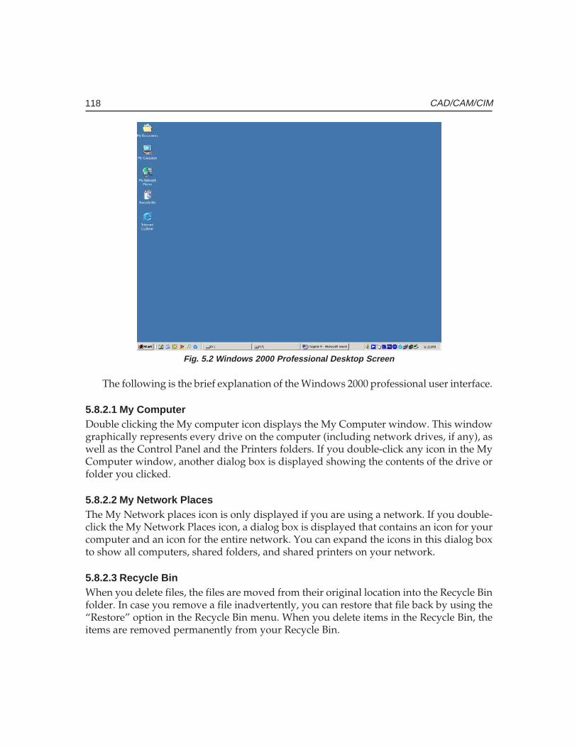
118 CAD/CAM/CIM
Fig. 5.2 Windows 2000 Professional Desktop Screen
The following is the brief explanation of the Windows 2000 professional user interface.
5.8.2.1 My ComputerDouble clicking the My computer icon displays the My Computer window. This windowgraphically represents every drive on the computer (including network drives, if any), aswell as the Control Panel and the Printers folders. If you double-click any icon in the MyComputer window, another dialog box is displayed showing the contents of the drive orfolder you clicked.
5.8.2.2 My Network PlacesThe My Network places icon is only displayed if you are using a network. If you double-click the My Network Places icon, a dialog box is displayed that contains an icon for yourcomputer and an icon for the entire network. You can expand the icons in this dialog boxto show all computers, shared folders, and shared printers on your network.
5.8.2.3 Recycle BinWhen you delete files, the files are moved from their original location into the Recycle Binfolder. In case you remove a file inadvertently, you can restore that file back by using the“Restore” option in the Recycle Bin menu. When you delete items in the Recycle Bin, theitems are removed permanently from your Recycle Bin.
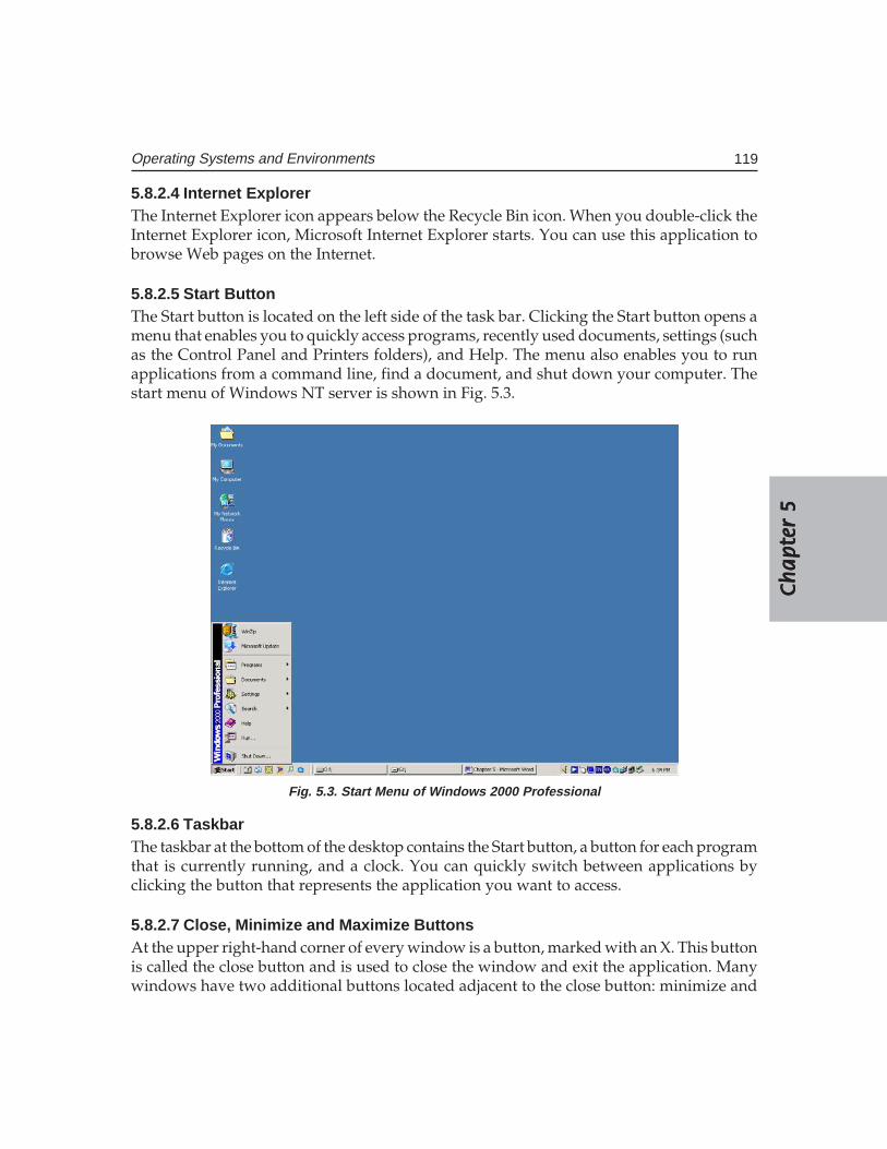
Ch
ap
ter
5C
ha
pte
r 5
Ch
ap
ter
5C
ha
pte
r 5
Ch
ap
ter
5
119Operating Systems and Environments
5.8.2.4 Internet ExplorerThe Internet Explorer icon appears below the Recycle Bin icon. When you double-click theInternet Explorer icon, Microsoft Internet Explorer starts. You can use this application tobrowse Web pages on the Internet.
5.8.2.5 Start ButtonThe Start button is located on the left side of the task bar. Clicking the Start button opens amenu that enables you to quickly access programs, recently used documents, settings (suchas the Control Panel and Printers folders), and Help. The menu also enables you to runapplications from a command line, find a document, and shut down your computer. Thestart menu of Windows NT server is shown in Fig. 5.3.
Fig. 5.3. Start Menu of Windows 2000 Professional
5.8.2.6 TaskbarThe taskbar at the bottom of the desktop contains the Start button, a button for each programthat is currently running, and a clock. You can quickly switch between applications byclicking the button that represents the application you want to access.
5.8.2.7 Close, Minimize and Maximize ButtonsAt the upper right-hand corner of every window is a button, marked with an X. This buttonis called the close button and is used to close the window and exit the application. Manywindows have two additional buttons located adjacent to the close button: minimize and
120 CAD/CAM/CIM
maximize buttons. The minimize button looks like an underscore on a button. Clickingthis button will minimize the application to its icon on the taskbar. The maximize buttonlooks like either a single box with a dark line across the top, or like two overlapping boxes,each with a dark line across the top. Clicking the maximize button switches between asmall view of the window and a full screen view of the window.
You can also access any file, folder, printer or application on your computer or on thenetwork in Windows 2000 Professional. Windows 2000 Professional is a useful tool forcopying, moving and deleting files. To access programs click the “Start” button on the leftcorner of the taskbar.
Windows 2000 Professional is a high-security capable operating system. Like WindowsNT Workstation, user logon and authentication is required. Security is controlled andadministered via a domain directory database. Windows 2000 Professional is optimizedfor server performance. Its client/server platform provides for powerful network features.
5.9 LINUX
The concept of open source software is almost as old as commercial software itself. RichardStallman founded the GNU project in 1983. In 1991 Linus Torwalds wrote a kernel for theopen source system which was later named as Linux. Linux is a full featured 32 bit multiuser and multitasking operating system and adheres to the common POSIX standards forUNIX. Linux features native TCP/IP support and a mature X Windows GUI interface. Itprovides a complete development environment for C, C++, and Java etc. As in UNIX allinteractions to OS are done through designated “users”. Linux is a good, reliable and stableplatform for developers. It has several GUI software development interfaces.
QUESTIONS
1. What are the functions of an operating system?2. Compare the functionalities of an operating system and an operating environment.3. Differentiate between control program and processing programs.4. Describe the architecture of UNIX operating system.5. Why is UNIX a popular operation system?6. What is a GUI? Why are GUI’s popular?7. Compare the functionalities in the different windows versions.8. Make a comparative study of UNIX and Windows NT.
�����������������
��� ������
� �����
Geometric modeling techniques like wire frame, surface and solid modeling have totallychanged not only the drawing office practices but also have helped to integrate design withanalysis, simulation and optimization as well as to seamlessly integrate design with downstreammanufacturing applications. Data created in geometric models can thus be directly passed onto all the application software packages like finite element analysis, mechanism analysis,CNC programming, inspection etc. Geometric modeling has therefore paved the way for CIM.The salient features of the different modeling techniques are discussed in this chapter. Thestarting point of new product development is conceptual design. The designer has to developthe shape of the product which in turn has to accommodate the functional parts inside. Whetherit is a consumer durable like a camera, and an electric iron, a washing machine, an automobile,an entertainment electronic item like television or a sports item like a golf club, shape designis a critical activity in product design. This chapter also discusses conceptual design techniquesand transfer of data to modeling software.
6.1 INTRODUCTION
Product development activity starts with the design of the product. As mentioned inChapter 2 this is a very critical activity which will influence the cost, performance, servicelife, quality, manufacturability, maintainability etc. The challenges before the productdesigners today are listed below:
• Higher customer quality expectations• Need to have innovation and originality in design• Need for global collaboration across and beyond the enterprise among designers,
customers and vendors to reduce development lead times• Need to evaluate feasibility throughout the design process• Ability to react quickly to design changes as and when change requests are made• Ability to express the design intent in terms of shape and function using the tools
available as well as the ability of the tools to transfer data back and forth seamlessly.Manufacturing of machine parts and components is carried out with the help of
drawings. The machine operator is provided with the drawing of the finished part and anoperation sheet which gives step by step instructions to produce the part. Drawings arealso required for process planning, tool design, production planning, and CNC
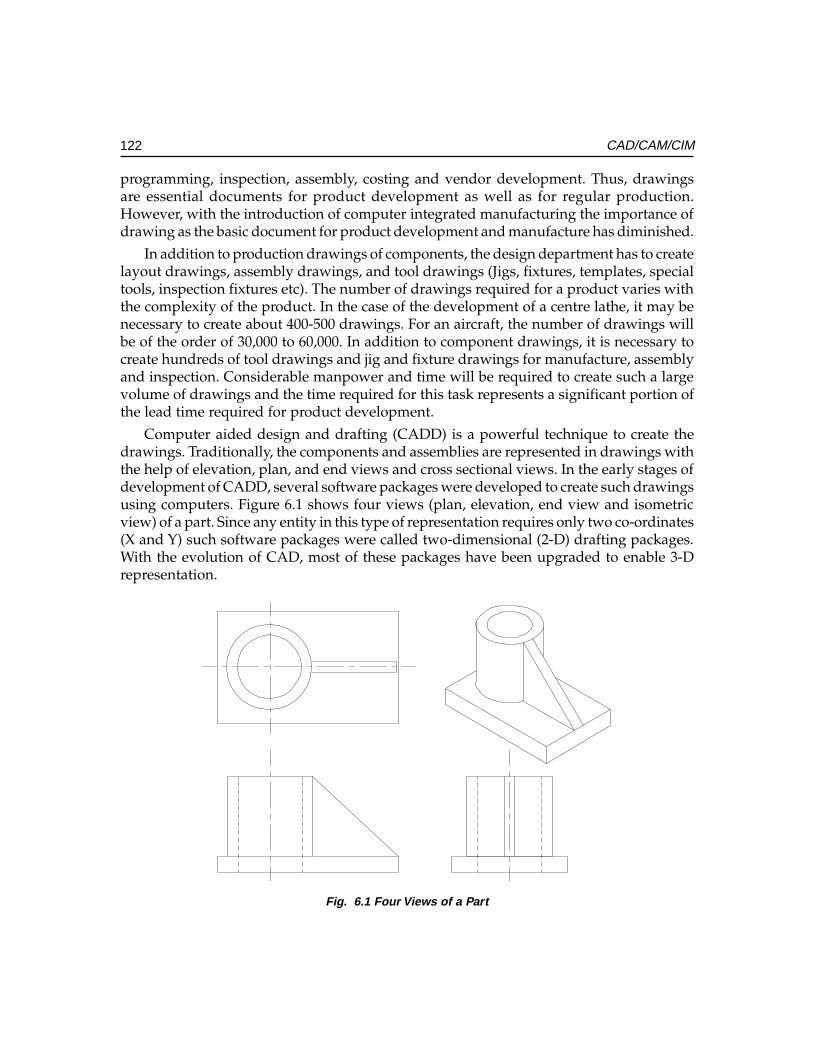
122 CAD/CAM/CIM
programming, inspection, assembly, costing and vendor development. Thus, drawingsare essential documents for product development as well as for regular production.However, with the introduction of computer integrated manufacturing the importance ofdrawing as the basic document for product development and manufacture has diminished.
In addition to production drawings of components, the design department has to createlayout drawings, assembly drawings, and tool drawings (Jigs, fixtures, templates, specialtools, inspection fixtures etc). The number of drawings required for a product varies withthe complexity of the product. In the case of the development of a centre lathe, it may benecessary to create about 400-500 drawings. For an aircraft, the number of drawings willbe of the order of 30,000 to 60,000. In addition to component drawings, it is necessary tocreate hundreds of tool drawings and jig and fixture drawings for manufacture, assemblyand inspection. Considerable manpower and time will be required to create such a largevolume of drawings and the time required for this task represents a significant portion ofthe lead time required for product development.
Computer aided design and drafting (CADD) is a powerful technique to create thedrawings. Traditionally, the components and assemblies are represented in drawings withthe help of elevation, plan, and end views and cross sectional views. In the early stages ofdevelopment of CADD, several software packages were developed to create such drawingsusing computers. Figure 6.1 shows four views (plan, elevation, end view and isometricview) of a part. Since any entity in this type of representation requires only two co-ordinates(X and Y) such software packages were called two-dimensional (2-D) drafting packages.With the evolution of CAD, most of these packages have been upgraded to enable 3-Drepresentation.
Fig. 6.1 Four Views of a Part
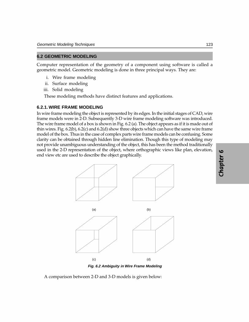
Ch
ap
ter
6C
ha
pte
r 6
Ch
ap
ter
6C
ha
pte
r 6
Ch
ap
ter
6
123Geometric Modeling Techniques
6.2 GEOMETRIC MODELING
Computer representation of the geometry of a component using software is called ageometric model. Geometric modeling is done in three principal ways. They are:
i. Wire frame modelingii. Surface modeling
iii. Solid modelingThese modeling methods have distinct features and applications.
6.2.1. WIRE FRAME MODELINGIn wire frame modeling the object is represented by its edges. In the initial stages of CAD, wireframe models were in 2-D. Subsequently 3-D wire frame modeling software was introduced.The wire frame model of a box is shown in Fig. 6.2 (a). The object appears as if it is made out ofthin wires. Fig. 6.2(b), 6.2(c) and 6.2(d) show three objects which can have the same wire framemodel of the box. Thus in the case of complex parts wire frame models can be confusing. Someclarity can be obtained through hidden line elimination. Though this type of modeling maynot provide unambiguous understanding of the object, this has been the method traditionallyused in the 2-D representation of the object, where orthographic views like plan, elevation,end view etc are used to describe the object graphically.
(d)(c)
(b)(a)
Fig. 6.2 Ambiguity in Wire Frame Modeling
A comparison between 2-D and 3-D models is given below:
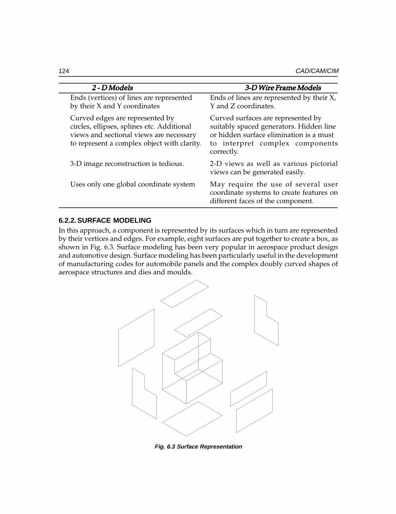
124 CAD/CAM/CIM
2 - D Models2 - D Models2 - D Models2 - D Models2 - D Models 3-D Wire Frame Models3-D Wire Frame Models3-D Wire Frame Models3-D Wire Frame Models3-D Wire Frame ModelsEnds (vertices) of lines are represented Ends of lines are represented by their X,by their X and Y coordinates Y and Z coordinates.
Curved edges are represented by Curved surfaces are represented bycircles, ellipses, splines etc. Additional suitably spaced generators. Hidden lineviews and sectional views are necessary or hidden surface elimination is a mustto represent a complex object with clarity. to interpret complex components
correctly.
3-D image reconstruction is tedious. 2-D views as well as various pictorialviews can be generated easily.
Uses only one global coordinate system May require the use of several usercoordinate systems to create features ondifferent faces of the component.
6.2.2.SURFACE MODELINGIn this approach, a component is represented by its surfaces which in turn are representedby their vertices and edges. For example, eight surfaces are put together to create a box, asshown in Fig. 6.3. Surface modeling has been very popular in aerospace product designand automotive design. Surface modeling has been particularly useful in the developmentof manufacturing codes for automobile panels and the complex doubly curved shapes ofaerospace structures and dies and moulds.
Fig. 6.3 Surface Representation
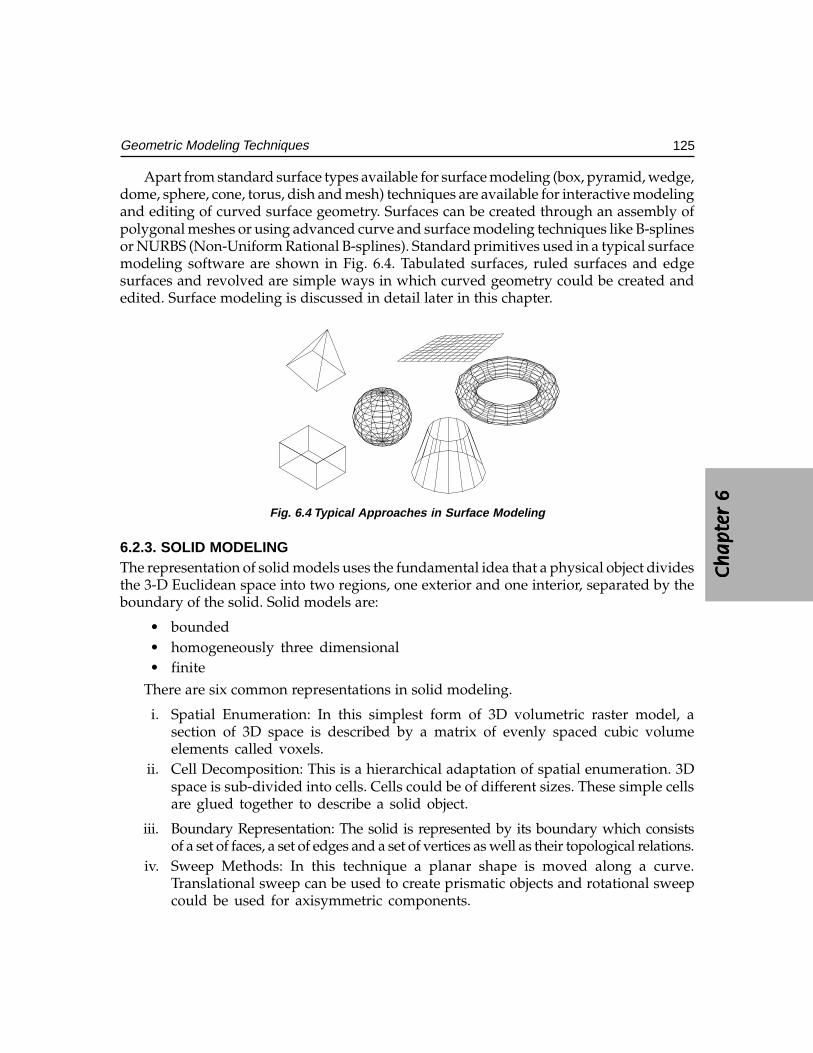
Ch
ap
ter
6C
ha
pte
r 6
Ch
ap
ter
6C
ha
pte
r 6
Ch
ap
ter
6
125Geometric Modeling Techniques
Apart from standard surface types available for surface modeling (box, pyramid, wedge,dome, sphere, cone, torus, dish and mesh) techniques are available for interactive modelingand editing of curved surface geometry. Surfaces can be created through an assembly ofpolygonal meshes or using advanced curve and surface modeling techniques like B-splinesor NURBS (Non-Uniform Rational B-splines). Standard primitives used in a typical surfacemodeling software are shown in Fig. 6.4. Tabulated surfaces, ruled surfaces and edgesurfaces and revolved are simple ways in which curved geometry could be created andedited. Surface modeling is discussed in detail later in this chapter.
Fig. 6.4 Typical Approaches in Surface Modeling
6.2.3. SOLID MODELINGThe representation of solid models uses the fundamental idea that a physical object dividesthe 3-D Euclidean space into two regions, one exterior and one interior, separated by theboundary of the solid. Solid models are:
• bounded• homogeneously three dimensional• finite
There are six common representations in solid modeling.
i. Spatial Enumeration: In this simplest form of 3D volumetric raster model, asection of 3D space is described by a matrix of evenly spaced cubic volumeelements called voxels.
ii. Cell Decomposition: This is a hierarchical adaptation of spatial enumeration. 3Dspace is sub-divided into cells. Cells could be of different sizes. These simple cellsare glued together to describe a solid object.
iii. Boundary Representation: The solid is represented by its boundary which consistsof a set of faces, a set of edges and a set of vertices as well as their topological relations.
iv. Sweep Methods: In this technique a planar shape is moved along a curve.Translational sweep can be used to create prismatic objects and rotational sweepcould be used for axisymmetric components.
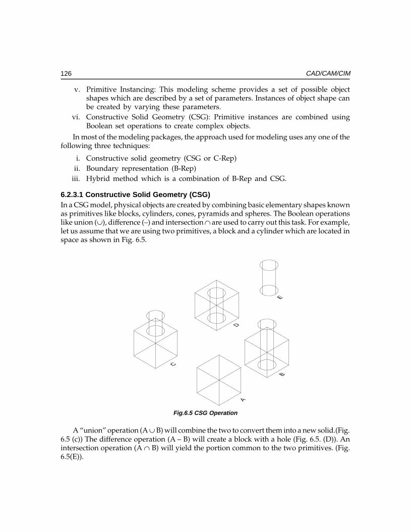
126 CAD/CAM/CIM
v. Primitive Instancing: This modeling scheme provides a set of possible objectshapes which are described by a set of parameters. Instances of object shape canbe created by varying these parameters.
vi. Constructive Solid Geometry (CSG): Primitive instances are combined usingBoolean set operations to create complex objects.
In most of the modeling packages, the approach used for modeling uses any one of thefollowing three techniques:
i. Constructive solid geometry (CSG or C-Rep)ii. Boundary representation (B-Rep)
iii. Hybrid method which is a combination of B-Rep and CSG.
6.2.3.1 Constructive Solid Geometry (CSG)In a CSG model, physical objects are created by combining basic elementary shapes knownas primitives like blocks, cylinders, cones, pyramids and spheres. The Boolean operationslike union (∪), difference (–) and intersection ∩ are used to carry out this task. For example,let us assume that we are using two primitives, a block and a cylinder which are located inspace as shown in Fig. 6.5.
Fig.6.5 CSG Operation
A “union” operation (A ∪ B) will combine the two to convert them into a new solid.(Fig.6.5 (c)) The difference operation (A – B) will create a block with a hole (Fig. 6.5. (D)). Anintersection operation (A ∩ B) will yield the portion common to the two primitives. (Fig.6.5(E)).
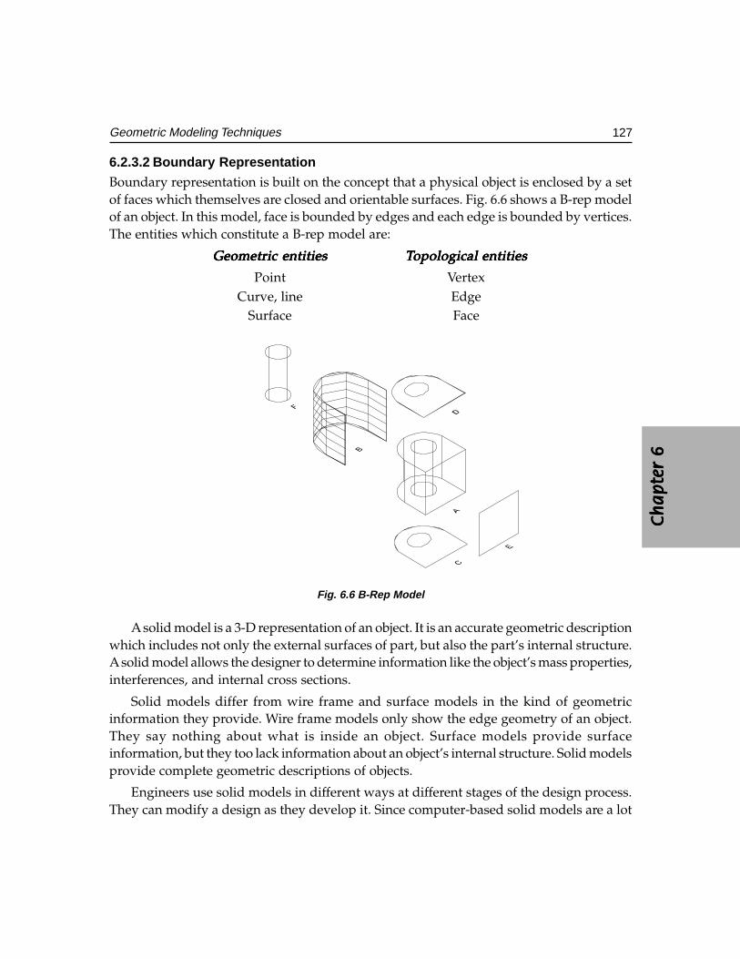
Ch
ap
ter
6C
ha
pte
r 6
Ch
ap
ter
6C
ha
pte
r 6
Ch
ap
ter
6
127Geometric Modeling Techniques
6.2.3.2 Boundary RepresentationBoundary representation is built on the concept that a physical object is enclosed by a setof faces which themselves are closed and orientable surfaces. Fig. 6.6 shows a B-rep modelof an object. In this model, face is bounded by edges and each edge is bounded by vertices.The entities which constitute a B-rep model are:
Geometric entitiesGeometric entitiesGeometric entitiesGeometric entitiesGeometric entities TTTTTopological entitiesopological entitiesopological entitiesopological entitiesopological entities
Point VertexCurve, line Edge
Surface Face
Fig. 6.6 B-Rep Model
A solid model is a 3-D representation of an object. It is an accurate geometric descriptionwhich includes not only the external surfaces of part, but also the part’s internal structure.A solid model allows the designer to determine information like the object’s mass properties,interferences, and internal cross sections.
Solid models differ from wire frame and surface models in the kind of geometricinformation they provide. Wire frame models only show the edge geometry of an object.They say nothing about what is inside an object. Surface models provide surfaceinformation, but they too lack information about an object’s internal structure. Solid modelsprovide complete geometric descriptions of objects.
Engineers use solid models in different ways at different stages of the design process.They can modify a design as they develop it. Since computer-based solid models are a lot
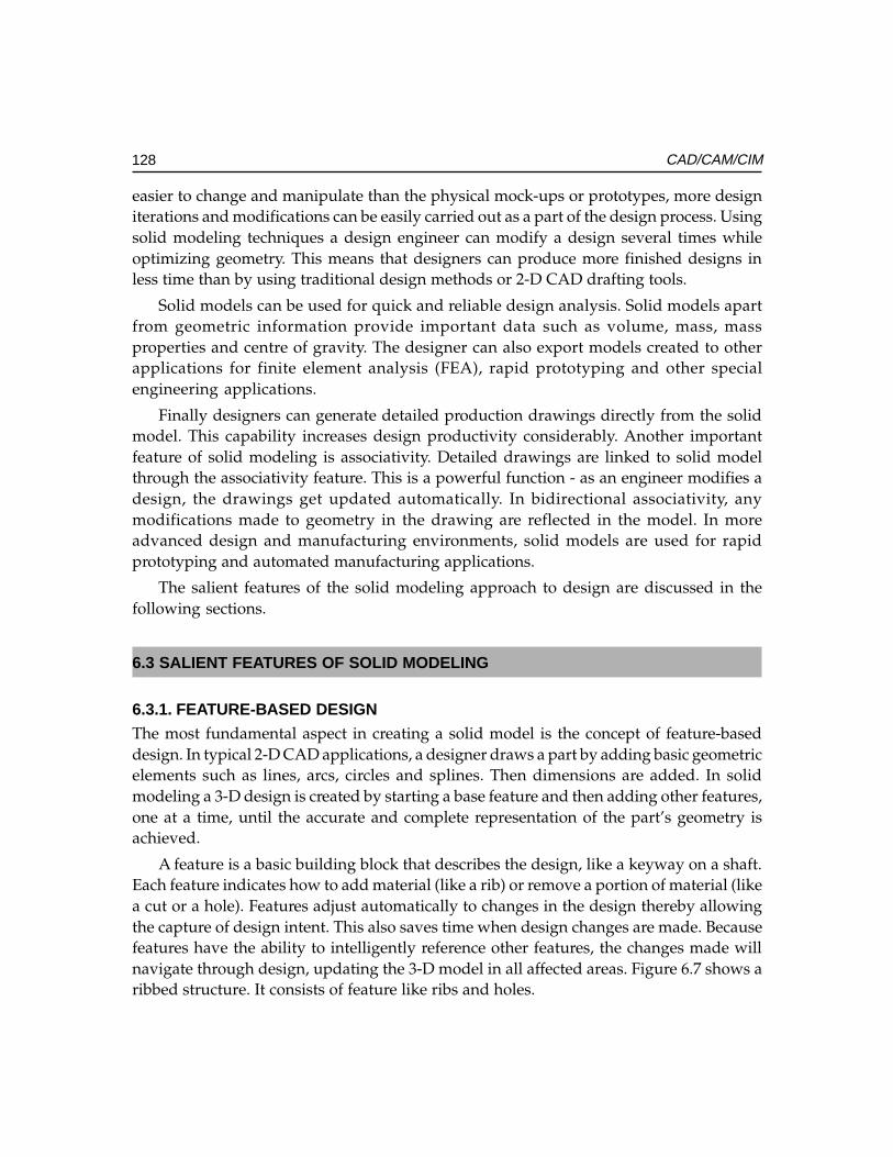
128 CAD/CAM/CIM
easier to change and manipulate than the physical mock-ups or prototypes, more designiterations and modifications can be easily carried out as a part of the design process. Usingsolid modeling techniques a design engineer can modify a design several times whileoptimizing geometry. This means that designers can produce more finished designs inless time than by using traditional design methods or 2-D CAD drafting tools.
Solid models can be used for quick and reliable design analysis. Solid models apartfrom geometric information provide important data such as volume, mass, massproperties and centre of gravity. The designer can also export models created to otherapplications for finite element analysis (FEA), rapid prototyping and other specialengineering applications.
Finally designers can generate detailed production drawings directly from the solidmodel. This capability increases design productivity considerably. Another importantfeature of solid modeling is associativity. Detailed drawings are linked to solid modelthrough the associativity feature. This is a powerful function - as an engineer modifies adesign, the drawings get updated automatically. In bidirectional associativity, anymodifications made to geometry in the drawing are reflected in the model. In moreadvanced design and manufacturing environments, solid models are used for rapidprototyping and automated manufacturing applications.
The salient features of the solid modeling approach to design are discussed in thefollowing sections.
6.3 SALIENT FEATURES OF SOLID MODELING
6.3.1. FEATURE-BASED DESIGNThe most fundamental aspect in creating a solid model is the concept of feature-baseddesign. In typical 2-D CAD applications, a designer draws a part by adding basic geometricelements such as lines, arcs, circles and splines. Then dimensions are added. In solidmodeling a 3-D design is created by starting a base feature and then adding other features,one at a time, until the accurate and complete representation of the part’s geometry isachieved.
A feature is a basic building block that describes the design, like a keyway on a shaft.Each feature indicates how to add material (like a rib) or remove a portion of material (likea cut or a hole). Features adjust automatically to changes in the design thereby allowingthe capture of design intent. This also saves time when design changes are made. Becausefeatures have the ability to intelligently reference other features, the changes made willnavigate through design, updating the 3-D model in all affected areas. Figure 6.7 shows aribbed structure. It consists of feature like ribs and holes.
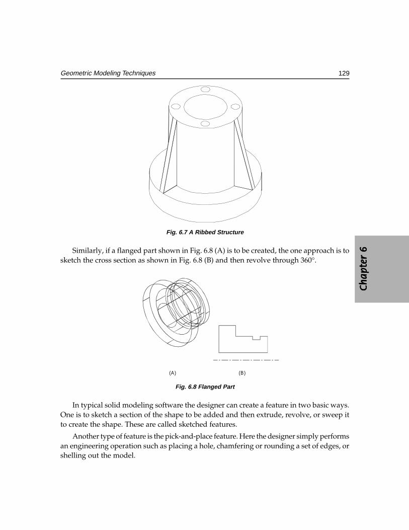
Ch
ap
ter
6C
ha
pte
r 6
Ch
ap
ter
6C
ha
pte
r 6
Ch
ap
ter
6
129Geometric Modeling Techniques
Fig. 6.7 A Ribbed Structure
Similarly, if a flanged part shown in Fig. 6.8 (A) is to be created, the one approach is tosketch the cross section as shown in Fig. 6.8 (B) and then revolve through 360°.
(A) (B)
Fig. 6.8 Flanged Part
In typical solid modeling software the designer can create a feature in two basic ways.One is to sketch a section of the shape to be added and then extrude, revolve, or sweep itto create the shape. These are called sketched features.
Another type of feature is the pick-and-place feature. Here the designer simply performsan engineering operation such as placing a hole, chamfering or rounding a set of edges, orshelling out the model.
130 CAD/CAM/CIM
An important component of every feature is its dimensions. Dimensions are thevariables that one changes in order to make the design update automatically. When adimension is changed the solid modeling software recalculates the geometry.
Design of a part always begins with a base feature. This is a basic shape, such as ablock or a cylinder that approximates the shape of the part one wants to design. Then byadding familiar design features like protrusions, cuts, ribs, keyways, rounds, holes, andothers the geometry of a part is created.
This process represents true design. Unlike many CAD applications in which designingmeans drawing a picture of the part, working with the feature-based solid modeling methodis more like sculpting designs from solid material.
Features/available in typical solid modeling software are:
Extrude Revolve ThinBlend Slot CutProtrusion Shaft RoundHole Flange RibChamfer Push DomeDraft Ear ShellOffset LipPipe Sweep
6.3.2. MODELING TOOLSWhen a 3-D model is built the designer describes the features that make up a part. Partsare put together to make an assembly, and then documentation is made.
SketchingSketchingSketchingSketchingSketchingThe first step in creating many 3-D features is sketching a 2-D section. Then by using
appropriate instructions the design conveys the information regarding how far to extendthis section in a space. The third dimension is created this way. For instance, a 30 mmcircle extruded 50 mm through space produces a cylinder 30 mm diameter and 50 mmhigh. The circle is the sketched section of the cylinder.
CrCrCrCrCreating Partseating Partseating Partseating Partseating PartsAs mentioned earlier solid modeler uses features such as cuts, protrusions, holes,
chamfers, and other basic shapes to build part geometry. The designer gets the informationabout the geometry of a feature (like the size and shape of cuts and protrusions), from asketcher window.
As the features are added the geometry of the part is enhanced. By adding togeometry one feature at a time, parts with very complex geometry can be created asshown in Fig. 6.9.
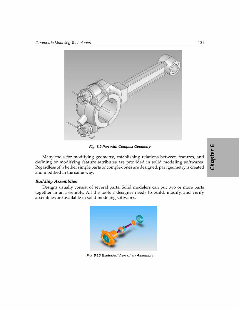
Ch
ap
ter
6C
ha
pte
r 6
Ch
ap
ter
6C
ha
pte
r 6
Ch
ap
ter
6
131Geometric Modeling Techniques
Fig. 6.9 Part with Complex Geometry
Many tools for modifying geometry, establishing relations between features, anddefining or modifying feature attributes are provided in solid modeling softwares.Regardless of whether simple parts or complex ones are designed, part geometry is createdand modified in the same way.
Building Building Building Building Building AssembliesAssembliesAssembliesAssembliesAssembliesDesigns usually consist of several parts. Solid modelers can put two or more parts
together in an assembly. All the tools a designer needs to build, modify, and verifyassemblies are available in solid modeling softwares.
Fig. 6.10 Exploded View of an Assembly
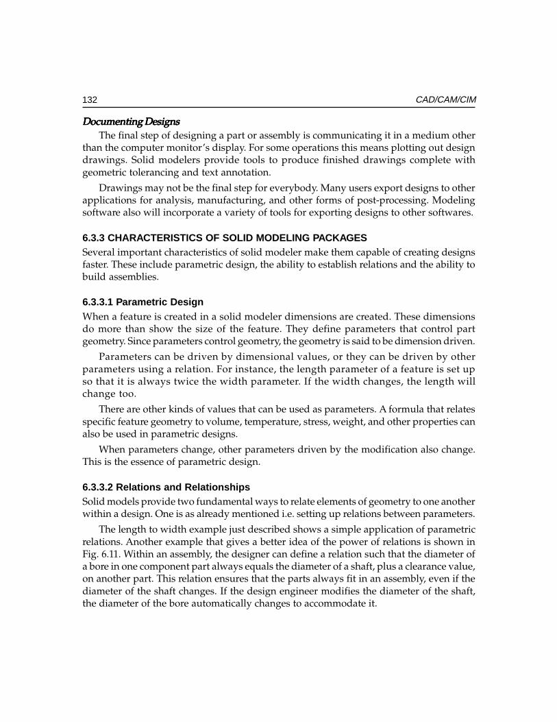
132 CAD/CAM/CIM
Documenting DesignsDocumenting DesignsDocumenting DesignsDocumenting DesignsDocumenting DesignsThe final step of designing a part or assembly is communicating it in a medium other
than the computer monitor’s display. For some operations this means plotting out designdrawings. Solid modelers provide tools to produce finished drawings complete withgeometric tolerancing and text annotation.
Drawings may not be the final step for everybody. Many users export designs to otherapplications for analysis, manufacturing, and other forms of post-processing. Modelingsoftware also will incorporate a variety of tools for exporting designs to other softwares.
6.3.3 CHARACTERISTICS OF SOLID MODELING PACKAGESSeveral important characteristics of solid modeler make them capable of creating designsfaster. These include parametric design, the ability to establish relations and the ability tobuild assemblies.
6.3.3.1 Parametric DesignWhen a feature is created in a solid modeler dimensions are created. These dimensionsdo more than show the size of the feature. They define parameters that control partgeometry. Since parameters control geometry, the geometry is said to be dimension driven.
Parameters can be driven by dimensional values, or they can be driven by otherparameters using a relation. For instance, the length parameter of a feature is set upso that it is always twice the width parameter. If the width changes, the length willchange too.
There are other kinds of values that can be used as parameters. A formula that relatesspecific feature geometry to volume, temperature, stress, weight, and other properties canalso be used in parametric designs.
When parameters change, other parameters driven by the modification also change.This is the essence of parametric design.
6.3.3.2 Relations and RelationshipsSolid models provide two fundamental ways to relate elements of geometry to one anotherwithin a design. One is as already mentioned i.e. setting up relations between parameters.
The length to width example just described shows a simple application of parametricrelations. Another example that gives a better idea of the power of relations is shown inFig. 6.11. Within an assembly, the designer can define a relation such that the diameter ofa bore in one component part always equals the diameter of a shaft, plus a clearance value,on another part. This relation ensures that the parts always fit in an assembly, even if thediameter of the shaft changes. If the design engineer modifies the diameter of the shaft,the diameter of the bore automatically changes to accommodate it.
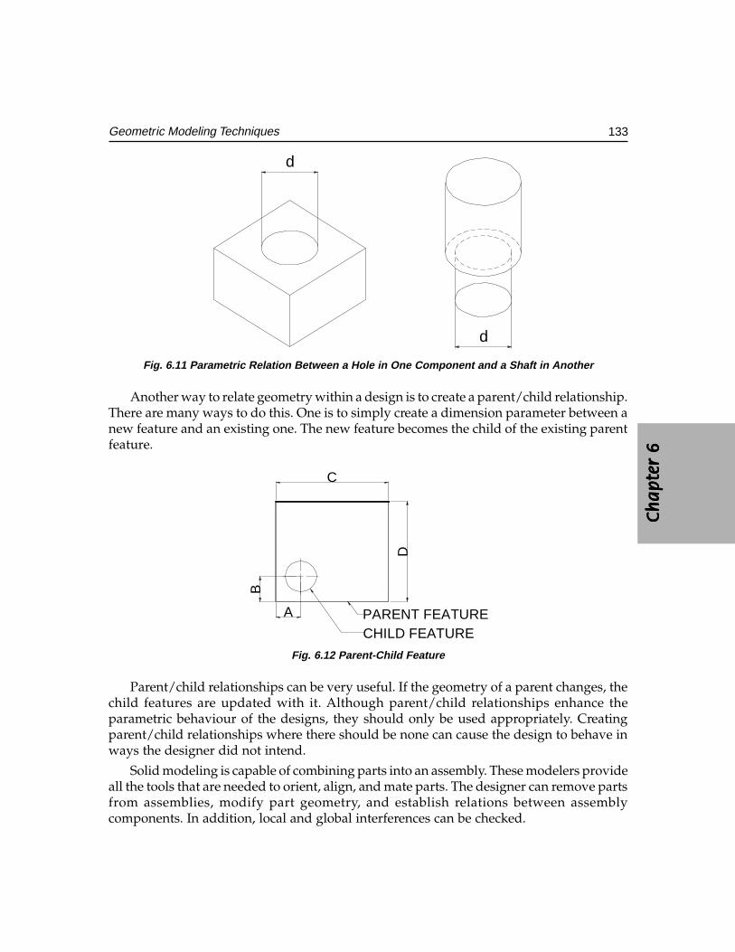
Ch
ap
ter
6C
ha
pte
r 6
Ch
ap
ter
6C
ha
pte
r 6
Ch
ap
ter
6
133Geometric Modeling Techniques
d
d
Fig. 6.11 Parametric Relation Between a Hole in One Component and a Shaft in Another
Another way to relate geometry within a design is to create a parent/child relationship.There are many ways to do this. One is to simply create a dimension parameter between anew feature and an existing one. The new feature becomes the child of the existing parentfeature.
CHILD FEATUREPARENT FEATUREA
B
D
C
Fig. 6.12 Parent-Child Feature
Parent/child relationships can be very useful. If the geometry of a parent changes, thechild features are updated with it. Although parent/child relationships enhance theparametric behaviour of the designs, they should only be used appropriately. Creatingparent/child relationships where there should be none can cause the design to behave inways the designer did not intend.
Solid modeling is capable of combining parts into an assembly. These modelers provideall the tools that are needed to orient, align, and mate parts. The designer can remove partsfrom assemblies, modify part geometry, and establish relations between assemblycomponents. In addition, local and global interferences can be checked.
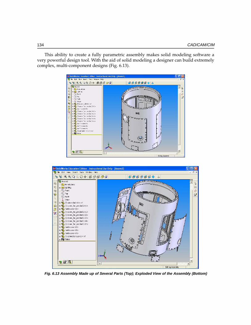
134 CAD/CAM/CIM
This ability to create a fully parametric assembly makes solid modeling software avery powerful design tool. With the aid of solid modeling a designer can build extremelycomplex, multi-component designs (Fig. 6.13).
Fig. 6.13 Assembly Made up of Several Parts (Top); Exploded View of the Assembly (Bottom)
Ch
ap
ter
6C
ha
pte
r 6
Ch
ap
ter
6C
ha
pte
r 6
Ch
ap
ter
6
135Geometric Modeling Techniques
All designs, whether big or small, begin with an idea. As the idea takes form, so do certainaspects of the idea. What is the purpose of the design? What are the key features and componentsthat make the design achieve its objectives? How do the components fit together? And whatother questions are to be satisfactorily answered to make it a viable design? These are some ofthe issues the designer has to answer while carrying out a design.
6.3.3.3 Behaviour ModelingBehavior modeling is the latest development in mechanical CAD. It gives the designersmore efficient and adaptable ways of creating designs. It helps to synthesize requiredfunctional behavior, design context and geometry. Through an intelligent process ofknowledge capture and iterative solving behavior modeling allows engineers to pursuehighly innovative and robust designs. The process of behavior modeling involves:
Smart models:Smart models:Smart models:Smart models:Smart models: These encapsulate engineering intelligence. Designs are created usingfeature based techniques, which capture geometry, specifications, design intent, and processknowledge-all at the design level.
Engineering objective based design: Engineering objective based design: Engineering objective based design: Engineering objective based design: Engineering objective based design: Design tools use feature based designspecifications within the smart model to drive and adapt product design. Using objectivedriven functions, engineers can arrive at an optimum design, even in designs with severalvariables and constraints and multiple objective criteria.
Open extensible envirOpen extensible envirOpen extensible envirOpen extensible envirOpen extensible environment:onment:onment:onment:onment: This facilitates associative bi-directionalcommunication to any external application like analysis, manufacturing etc. at the featurelevel of the design ensuring that model reflects the changes incorporated in otherapplications.
Behavior modeling helps to create designs which are more innovative, differentiableand more responsive to customers’ requirements. With the help of objective driven designprocess engineers can focus on key design issues, and evolve optimal design solutions forbetter performance and functionality.
Behavior modeling helps to make electronic product designs more complete.Behavior modeling strategy advances feature-based modeling to accommodate a set
of adaptive process features that go beyond the traditional core geometric features. Thesefeatures accommodate a variety of information that further specifies the intent andperformance of the design. There are two distinct categories of adaptive design. Applicationfeatures describe process information. Behavioral features contain engineering andfunctional specifications. Application features encapsulate product and process information.Behavioral features define component assembly connectivity, using welds, or pins or sliderjoints. When behavioral features consist of assembly connectivity information, includingany assembly constraints, the assembly design process automatically implements thatinformation to execute functional behavior and purpose. By capturing original design intent,product designs retain their integrity, robustness, and performance while adapting tomarket and engineering changes. The adaptive process features make smart models highlyflexible. As the engineers make changes to the smart models, the models regenerate toaccommodate all their features and context. This highly flexible adaptation makes smart
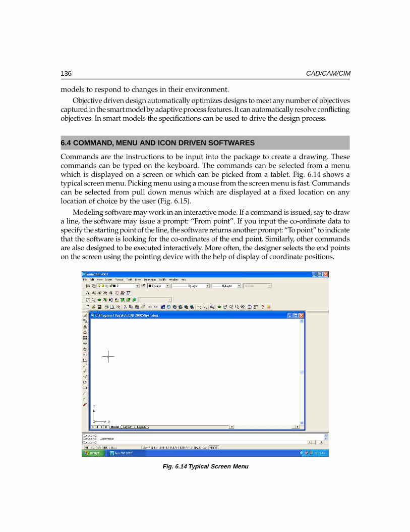
136 CAD/CAM/CIM
models to respond to changes in their environment.Objective driven design automatically optimizes designs to meet any number of objectives
captured in the smart model by adaptive process features. It can automatically resolve conflictingobjectives. In smart models the specifications can be used to drive the design process.
6.4 COMMAND, MENU AND ICON DRIVEN SOFTWARES
Commands are the instructions to be input into the package to create a drawing. Thesecommands can be typed on the keyboard. The commands can be selected from a menuwhich is displayed on a screen or which can be picked from a tablet. Fig. 6.14 shows atypical screen menu. Picking menu using a mouse from the screen menu is fast. Commandscan be selected from pull down menus which are displayed at a fixed location on anylocation of choice by the user (Fig. 6.15).
Modeling software may work in an interactive mode. If a command is issued, say to drawa line, the software may issue a prompt: “From point”. If you input the co-ordinate data tospecify the starting point of the line, the software returns another prompt: “To point” to indicatethat the software is looking for the co-ordinates of the end point. Similarly, other commandsare also designed to be executed interactively. More often, the designer selects the end pointson the screen using the pointing device with the help of display of coordinate positions.
Fig. 6.14 Typical Screen Menu
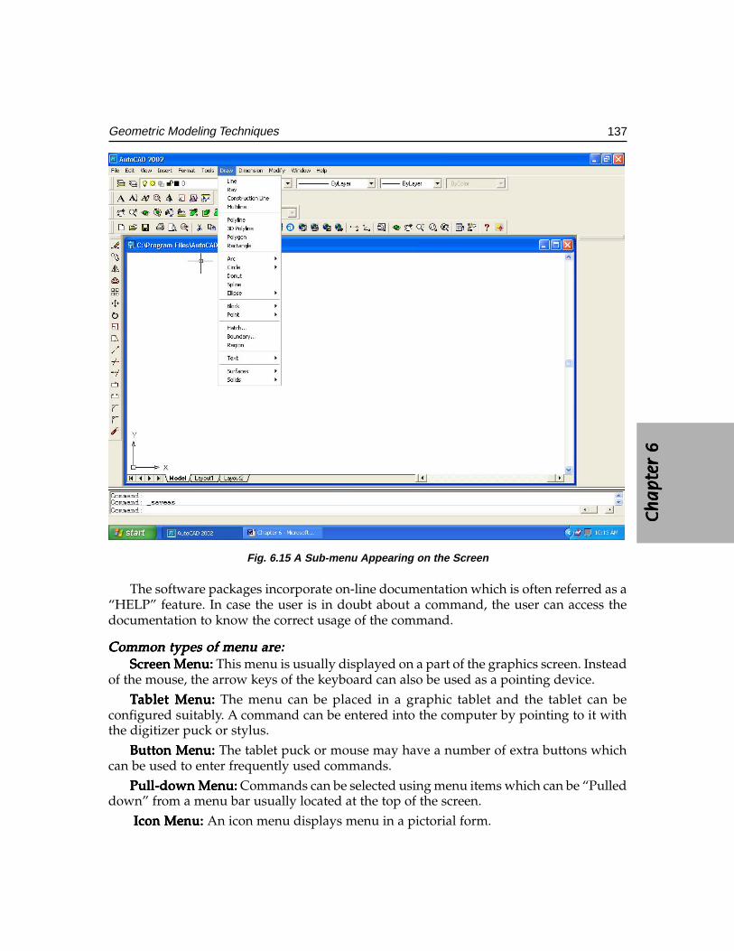
Ch
ap
ter
6C
ha
pte
r 6
Ch
ap
ter
6C
ha
pte
r 6
Ch
ap
ter
6
137Geometric Modeling Techniques
Fig. 6.15 A Sub-menu Appearing on the Screen
The software packages incorporate on-line documentation which is often referred as a“HELP” feature. In case the user is in doubt about a command, the user can access thedocumentation to know the correct usage of the command.
Common types of menu arCommon types of menu arCommon types of menu arCommon types of menu arCommon types of menu are:e:e:e:e:ScrScrScrScrScreen Menu: een Menu: een Menu: een Menu: een Menu: This menu is usually displayed on a part of the graphics screen. Instead
of the mouse, the arrow keys of the keyboard can also be used as a pointing device.
TTTTTablet Menu:ablet Menu:ablet Menu:ablet Menu:ablet Menu: The menu can be placed in a graphic tablet and the tablet can beconfigured suitably. A command can be entered into the computer by pointing to it withthe digitizer puck or stylus.
Button Menu:Button Menu:Button Menu:Button Menu:Button Menu: The tablet puck or mouse may have a number of extra buttons whichcan be used to enter frequently used commands.
Pull-down Menu:Pull-down Menu:Pull-down Menu:Pull-down Menu:Pull-down Menu: Commands can be selected using menu items which can be “Pulleddown” from a menu bar usually located at the top of the screen.
Icon Menu: Icon Menu: Icon Menu: Icon Menu: Icon Menu: An icon menu displays menu in a pictorial form.
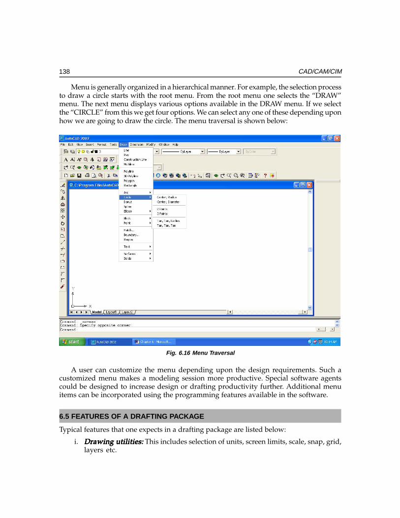
138 CAD/CAM/CIM
Menu is generally organized in a hierarchical manner. For example, the selection processto draw a circle starts with the root menu. From the root menu one selects the “DRAW”menu. The next menu displays various options available in the DRAW menu. If we selectthe “CIRCLE” from this we get four options. We can select any one of these depending uponhow we are going to draw the circle. The menu traversal is shown below:
Fig. 6.16 Menu Traversal
A user can customize the menu depending upon the design requirements. Such acustomized menu makes a modeling session more productive. Special software agentscould be designed to increase design or drafting productivity further. Additional menuitems can be incorporated using the programming features available in the software.
6.5 FEATURES OF A DRAFTING PACKAGE
Typical features that one expects in a drafting package are listed below:
i. Drawing utilities:Drawing utilities:Drawing utilities:Drawing utilities:Drawing utilities: This includes selection of units, screen limits, scale, snap, grid,layers etc.
Ch
ap
ter
6C
ha
pte
r 6
Ch
ap
ter
6C
ha
pte
r 6
Ch
ap
ter
6
139Geometric Modeling Techniques
ii. Entity drawing:Entity drawing:Entity drawing:Entity drawing:Entity drawing: Several standard entities like line, circle, arc, polyline, polygon,ellipse etc are available to create the model required.
iii. Edit commands:Edit commands:Edit commands:Edit commands:Edit commands: A number of commands are available to modify or copy orreplicate the entities or groups of entities in a model.
iv. StandarStandarStandarStandarStandard parts:d parts:d parts:d parts:d parts: Facilities are available to create symbols, shapes, and otherstandard parts. Frequently used parts can be stored as blocks which can beinserted into a drawing as and when required.
v. Display:Display:Display:Display:Display: The model can be enlarged, reduced in size, or moved across the screen,using display commands.
vi. CrCrCrCrCross hatching:oss hatching:oss hatching:oss hatching:oss hatching: Sectional plans can be indicated through cross hatching.vii. Dimensioning:Dimensioning:Dimensioning:Dimensioning:Dimensioning: Parts can be dimensioned using a number of standard
dimensioning systems.viii. Plotting:Plotting:Plotting:Plotting:Plotting: Facilities to get hard copies of drawings using a pen or electrostatic
plotter and printer will be available.ix. Configuration:Configuration:Configuration:Configuration:Configuration: A software has to be configured to a given hardware environment.x. Customization:Customization:Customization:Customization:Customization: Drafting productivity can be enhanced through customizing
software package.xi. Drawing interDrawing interDrawing interDrawing interDrawing interchange:change:change:change:change: It may be necessary to import or export drawing files
created in one software package to another. Facilities should be available to carryout this task. This is usually carried out by a post processor to convert the modelinto a neutral file like STEP and pre-processor to read the STEP file and convertthe data into the model.
These features are discussed in detail in the following sections.
6.6 DRAWING UTILITIES
Drawing utilities include several functions to help the creation and storage of drawings.These are discussed below:
6.6.1 SCREEN SIZEGenerally the screen is given a default size but the size can be modified as per therequirements. This facility is available in all softwares because various sizes of drawingsand figures will have to be created. Assembly drawings may require larger sizes whereaspart drawings require only smaller sizes. When the command for fixing the drawinglimits are invoked the values of the co-ordinates at the bottom left corner and the topright corner are specified as answer to the queries. Alternatively, the size of the drawingsheet (A4, A3, A2, A1 or A0) can be specified. Automatically the software re-fixes thesize of the screen. Default screen sizes and standard layouts are also incorporated in thedesign packages.
140 CAD/CAM/CIM
6.6.2 SCALINGIt may be necessary to fit a large sized drawing within a smaller drawing sheet size. Thedimensions can be automatically scaled for this purpose.
6.6.3 GRIDA grid facility is provided by the software to help the designer to estimate distances on thescreen. A grid is a matrix of points on the screen whose intervals can be chosen as required.The grid display can be switched on or off and this does not appear while making a hardcopy of the drawing.
6.6.4 SNAPThe drawing is created with the help of a cursor. The smallest movement of the cursor isone pixel. The cursor can be moved through a specific distance using SNAP feature. Thesnap interval can be chosen as described or can be made equal to grid interval. The snapmode can also be switched on or off as desired.
6.6.5 UNITSDifferent types of units are used for different applications. Examples are metric units andinch units. The dimension format may be scientific, decimal, engineering, architectural orfractional. Angles can be specified in decimal degrees, degree/minute/seconds or radians.
6.6.6 SPECIFYING POINTSA point can be specified using the following formats:
i. Cartesian co-ordinatesii. Polar co-ordinates
iii. Spherical co-ordinatesiv. Cylindrical co-ordinatesv. Relative co-ordinates
6.6.7 LINE TYPES, TEXT FONTS AND SHAPESIn a drawing several types of lines will be used and these types are already available (alibrary) and are given some designation by the software. The default will be the generallyused type of line, but as per the requirement the type of line can be chosen before any lineis drawn. Softwares also provide simple methods to create and add a new type of line tothe library of line types.
Similarly, texts to be added may be chosen from a library of fonts (standard, Italic,Complex, Simplex, Roman, Byte etc.) and before any text is added this choice has to bemade. The text size and the alignment of the text, and the starting and end points of textmay also be chosen. It may also be possible to left justify, centre justify and right justify thetext. New symbols can be also created and a library of shapes (with names) can be compiled.
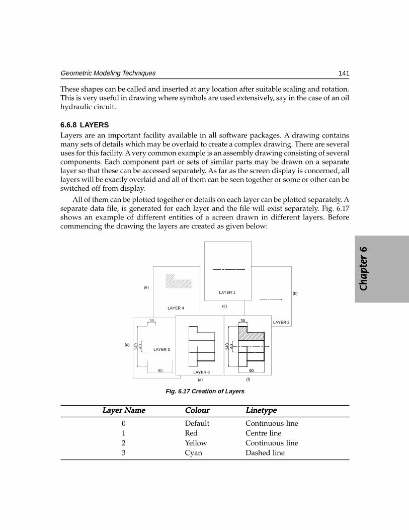
Ch
ap
ter
6C
ha
pte
r 6
Ch
ap
ter
6C
ha
pte
r 6
Ch
ap
ter
6
141Geometric Modeling Techniques
These shapes can be called and inserted at any location after suitable scaling and rotation.This is very useful in drawing where symbols are used extensively, say in the case of an oilhydraulic circuit.
6.6.8 LAYERSLayers are an important facility available in all software packages. A drawing containsmany sets of details which may be overlaid to create a complex drawing. There are severaluses for this facility. A very common example is an assembly drawing consisting of severalcomponents. Each component part or sets of similar parts may be drawn on a separatelayer so that these can be accessed separately. As far as the screen display is concerned, alllayers will be exactly overlaid and all of them can be seen together or some or other can beswitched off from display.
All of them can be plotted together or details on each layer can be plotted separately. Aseparate data file, is generated for each layer and the file will exist separately. Fig. 6.17shows an example of different entities of a screen drawn in different layers. Beforecommencing the drawing the layers are created as given below:
(f)
(e)
(d)
(c)
(b)
(a)
LAYER 4
LAYER 3
LAYER 2
LAYER 0
LAYER 1
30
90
40140
30
90
40140
90
30
40140
Fig. 6.17 Creation of Layers
Layer NameLayer NameLayer NameLayer NameLayer Name ColourColourColourColourColour LinetypeLinetypeLinetypeLinetypeLinetype
0 Default Continuous line1 Red Centre line2 Yellow Continuous line3 Cyan Dashed line
142 CAD/CAM/CIM
The part of drawing shown in Fig. 6.17(a) is drawn in Layer 0. Then layer 1 is set andthe centre line shown in Fig. 6.17(b) is drawn in layer 1. The entities drawn on layer 0 willalso be visible. For the sake of clarity they are not shown in Fig. 6.17(b).
Similarly hatching is drawn in layer 2 (Fig. 6.17(c)) and the dimensions in layer 3 asshown in Fig. 6.17(d). All the layers are superimposed and the drawing will look like asshown in Fig..6.7(e). Only one layer can be set an any given time. A layer can be given aspecific name. A number of layers can be used in a drawing. It is possible to use more thanone color and one line type in a layer. However it is better to use only one color and oneline type in a layer. A layer can be switched on or off as and when needed. When a layer isswitched off the contents of that layer are not displayed on the screen.
6.6.9 SAVING A DRAWINGAfter a drawing is created it is saved with a file name. The drawing file may have extensionslike .PRT or .DWG.
6.6.10 FILE UTILITIESDrafting softwares offer the following file utilities:
Directory serviceDelete filesRename filesCopy filesUnlock filesEdit a file
In addition, it is normally possible to access the operating system commands during adrafting session.
6.7 ENTITIES
A drawing is created using a number of entities. A large number of options are provided todraw the entities depending upon the requirements. The common entities used for draftingare listed below:
Point Arc
Line Trace
Circle Polyline (2D & 3D)
Polygon Doughnut
Ellipse Solid
Some drafting packages use constraint based construction method. Fixing constraintsallows interactive creations of variants.
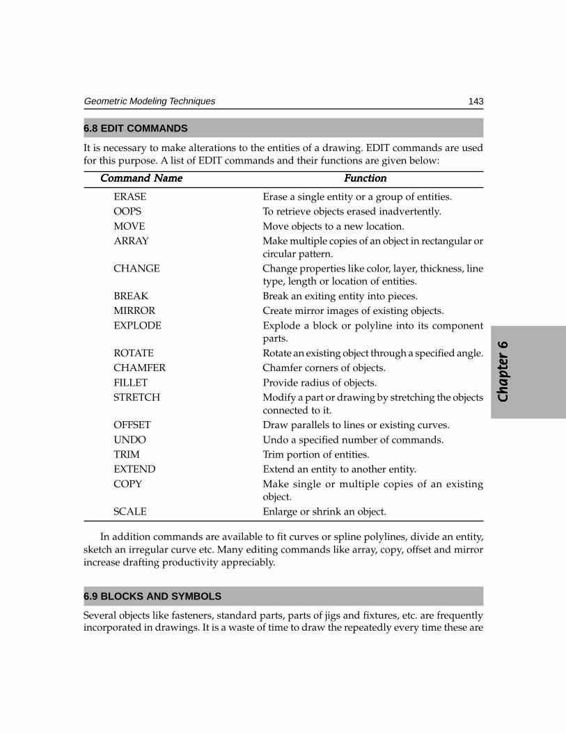
Ch
ap
ter
6C
ha
pte
r 6
Ch
ap
ter
6C
ha
pte
r 6
Ch
ap
ter
6
143Geometric Modeling Techniques
6.8 EDIT COMMANDS
It is necessary to make alterations to the entities of a drawing. EDIT commands are usedfor this purpose. A list of EDIT commands and their functions are given below:
Command NameCommand NameCommand NameCommand NameCommand Name FunctionFunctionFunctionFunctionFunction
ERASE Erase a single entity or a group of entities.OOPS To retrieve objects erased inadvertently.MOVE Move objects to a new location.ARRAY Make multiple copies of an object in rectangular or
circular pattern.CHANGE Change properties like color, layer, thickness, line
type, length or location of entities.BREAK Break an exiting entity into pieces.MIRROR Create mirror images of existing objects.EXPLODE Explode a block or polyline into its component
parts.ROTATE Rotate an existing object through a specified angle.CHAMFER Chamfer corners of objects.FILLET Provide radius of objects.STRETCH Modify a part or drawing by stretching the objects
connected to it.OFFSET Draw parallels to lines or existing curves.UNDO Undo a specified number of commands.TRIM Trim portion of entities.EXTEND Extend an entity to another entity.COPY Make single or multiple copies of an existing
object.SCALE Enlarge or shrink an object.
In addition commands are available to fit curves or spline polylines, divide an entity,sketch an irregular curve etc. Many editing commands like array, copy, offset and mirrorincrease drafting productivity appreciably.
6.9 BLOCKS AND SYMBOLS
Several objects like fasteners, standard parts, parts of jigs and fixtures, etc. are frequentlyincorporated in drawings. It is a waste of time to draw the repeatedly every time these are
144 CAD/CAM/CIM
used in drawings. A facility like block can be used for this purpose. A block is a group ofentities stored as a drawing file with a specific file name.
The block has a certain reference (insertion) point and an angular position. Any blockcan be inserted (INSERT command) into the drawing by indicating where the insertionpoint is to be located. The block can be scaled and rotated when it is being inserted into adrawing. Blocks can be revised and the drawing can be updated with the revised block.
It is also possible to create small objects, called shapes (within the drawing). These canalso be called and inserted at any location in a drawing just like a block. A good draftingsoftware should have this facility particularly for specialized drawings where small elementsare repeatedly drawn (example: oil hydraulics, electrical schematics, electronic circuits, surfaceroughness symbols, geometric tolerance symbols, weld symbols etc).
A standard parts library can be created using parametric programming facilitiesavailable in the design software packages. Many software packages also provide interfaceto high level languages like C to create such symbols.
6.10 DISPLAY
Display commands are useful to manipulate the drawings on the screen. A frequentlyused display command is ZOOM. A drawing or parts of a drawing usually picked by awindow option can be scaled up or down as required by ZOOM command. This makes itpossible to draw minute details accurately as well as to view the drawings in detail. In thecase of large drawings parts of the drawing may be out of the screen. In order to view suchhidden portion the PAN command is used. This command causes the drawing to be movedacross the screen. These two are powerful commands which facilitate large drawings to beprepared accurately. REDRAW command is used to refresh the screen.
The drawing database is updated using REGENERATE command. The screen can bedivided into 2, 3 or 4 parts to display different views of the same drawing usingVIEWPORTS command. Working in windows environment also allows simultaneousdisplays and interactions in multiple overlapping windows. This means that the user getsmultiple screens on one graphics screen. Windows can be shuffled by mouse click. It ispossible to expand the contents of one window into another. There are commands togenerate orthographic, isometric, perspective and axonometric projections. Dynamicviewing is also available in many packages.
6.11 CROSS HATCHING AND PATTERN FILLING
This is another important facility in drafting packages. All CAD softwares have this facility.The type of cross hatch line, the distance between lines and the angle of the filler lines canbe chosen. Usually a chain of commands starting from “HATCH” leads to the choice. Insome cases, instead of cross hatching with lines, a given pattern (available in a library ofpatterns) may also be chosen.
Ch
ap
ter
6C
ha
pte
r 6
Ch
ap
ter
6C
ha
pte
r 6
Ch
ap
ter
6
145Geometric Modeling Techniques
The choice of the area to be filled often may lead to difficulties. The best softwaressimply need the information in terms of a point and all the area enclosing this point willbe cross hatched or filled with patterns. All the connected area as along as it is not separatedby any curve or line will be filled.
Hatching with text inside the hatch area is another facility that should be available. Insuch cases, the text may have to be first drawn, before “HATCH” command.
6.12 DIMENSIONING
Dimensioning and adding annotations are very important in any drawing. If the dimensionof any object could be drawn just by pointing the object, it will be the best facility. Such afeature is known as automatic dimensioning, particularly if the dimensions are drawn inthe various views of the object. The features of an object in the various views are notrelated at all and they are treated as separate objects, by the software and so dimensioninghas to be done in the different views separately.
Generally linear dimensioning involves the drawing of two extension lines, (adimension line with arrow heads) separated from the object. Additionally tolerance valuesmay also have to be shown in some cases. It can thus be realized that dimensioning israther a complex process and a lot of decisions are involved. Simple inexpensive 2-Dsoftwares may not have an automatic dimensioning facility, but all of them should havethe capacity to do these by separate instructions from the operator.
Choice should be available to draw the extension lines, in terms of location, lengthand the distance from the object. The location choice is generally by picking the endpoints of the object to be dimensioned. This is done interactively by some input device.The arrow size, the location of dimension text etc. are chosen by specifying a seriesof dimension variables. The position of the dimension line is also input by picking,whereas its angular location is indicated by instructions like horizontal, vertical,aligned etc. Choice is available to use the same base line to dimension a number ofobjects and also for continuous dimension writing along a line. Usually the actuallength of the object is displayed by the computer but a different value can be chosenby the draftsman.
The dimensioning features also include angular, radial, diametrical, aligned andleader options. The associative dimensioning feature available in some software enablesautomatic change in the dimensioning when the entities are edited. Many CADsoftwares permit generation of dimension styles compatible to ISO, ANSI, DIN andother standards. Dimensioning feature can be customized by assigning appropriatevalues for various dimension variables. Fig. 6.18 and 6.19 show two drawings createdusing 2-D drafting.
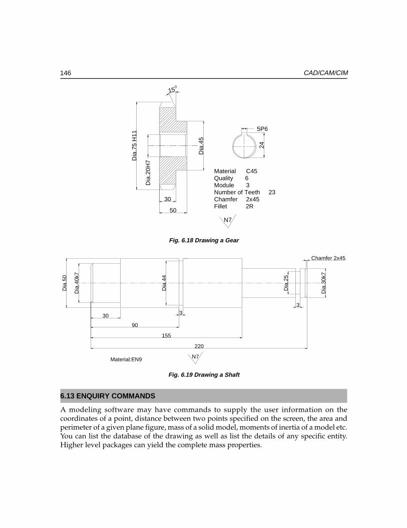
146 CAD/CAM/CIM
N7
Fillet 2RChamfer 2x45Number of Teeth 23Module 3Quality 6Material C45
015
24
5P6
Dia
.45
50
30
Dia
.75
H11
Dia
.20
H7
Fig. 6.18 Drawing a Gear
Material:EN9
220
155
90
30
Chamfer 2x45
33
Dia
.25
Dia
.44
Dia
.30k
7
Dia
.50
Dia
.40k
7
N7
Fig. 6.19 Drawing a Shaft
6.13 ENQUIRY COMMANDS
A modeling software may have commands to supply the user information on thecoordinates of a point, distance between two points specified on the screen, the area andperimeter of a given plane figure, mass of a solid model, moments of inertia of a model etc.You can list the database of the drawing as well as list the details of any specific entity.Higher level packages can yield the complete mass properties.
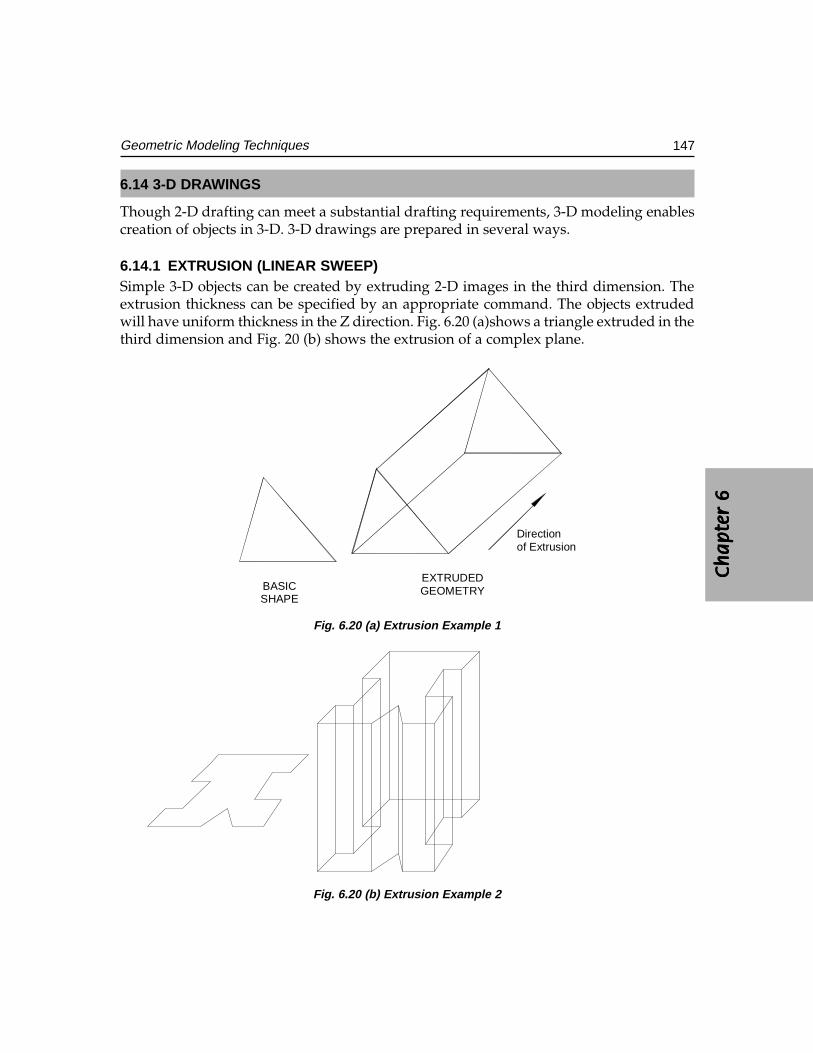
Ch
ap
ter
6C
ha
pte
r 6
Ch
ap
ter
6C
ha
pte
r 6
Ch
ap
ter
6
147Geometric Modeling Techniques
6.14 3-D DRAWINGS
Though 2-D drafting can meet a substantial drafting requirements, 3-D modeling enablescreation of objects in 3-D. 3-D drawings are prepared in several ways.
6.14.1 EXTRUSION (LINEAR SWEEP)Simple 3-D objects can be created by extruding 2-D images in the third dimension. Theextrusion thickness can be specified by an appropriate command. The objects extrudedwill have uniform thickness in the Z direction. Fig. 6.20 (a)shows a triangle extruded in thethird dimension and Fig. 20 (b) shows the extrusion of a complex plane.
of ExtrusionDirection
GEOMETRYEXTRUDED
SHAPEBASIC
Fig. 6.20 (a) Extrusion Example 1
Fig. 6.20 (b) Extrusion Example 2
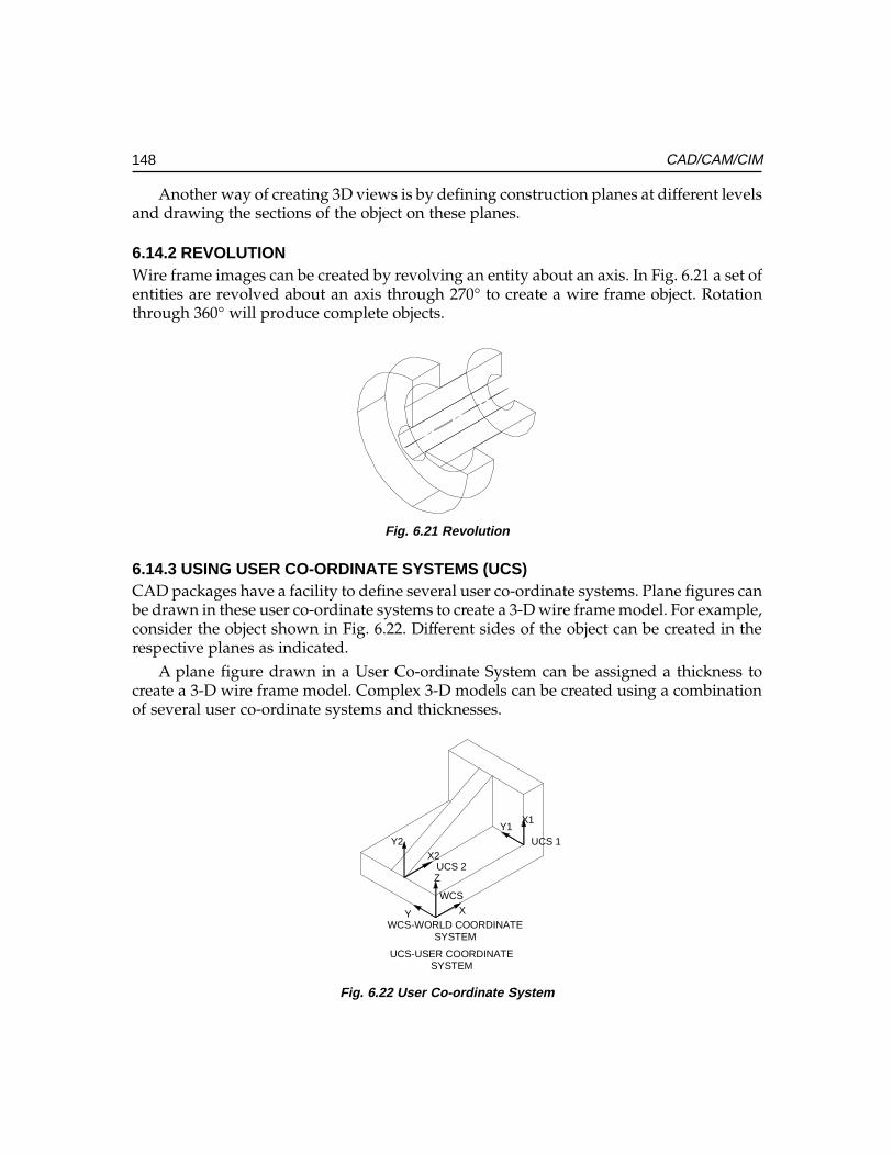
148 CAD/CAM/CIM
Another way of creating 3D views is by defining construction planes at different levelsand drawing the sections of the object on these planes.
6.14.2 REVOLUTIONWire frame images can be created by revolving an entity about an axis. In Fig. 6.21 a set ofentities are revolved about an axis through 270° to create a wire frame object. Rotationthrough 360° will produce complete objects.
Fig. 6.21 Revolution
6.14.3 USING USER CO-ORDINATE SYSTEMS (UCS)CAD packages have a facility to define several user co-ordinate systems. Plane figures canbe drawn in these user co-ordinate systems to create a 3-D wire frame model. For example,consider the object shown in Fig. 6.22. Different sides of the object can be created in therespective planes as indicated.
A plane figure drawn in a User Co-ordinate System can be assigned a thickness tocreate a 3-D wire frame model. Complex 3-D models can be created using a combinationof several user co-ordinate systems and thicknesses.
WCS
SYSTEMUCS-USER COORDINATE
SYSTEMWCS-WORLD COORDINATE
UCS 1
UCS 2
Y1X1
Y2X2
Z
Y X
Fig. 6.22 User Co-ordinate System
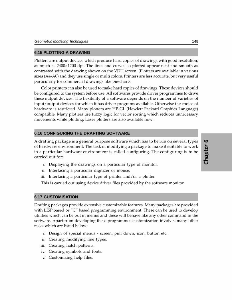
Ch
ap
ter
6C
ha
pte
r 6
Ch
ap
ter
6C
ha
pte
r 6
Ch
ap
ter
6
149Geometric Modeling Techniques
6.15 PLOTTING A DRAWING
Plotters are output devices which produce hard copies of drawings with good resolution,as much as 2400×1200 dpi. The lines and curves so plotted appear neat and smooth ascontrasted with the drawing shown on the VDU screen. (Plotters are available in varioussizes (A4-A0) and they use single or multi colors. Printers are less accurate, but very usefulparticularly for commercial drawings like pie-charts.
Color printers can also be used to make hard copies of drawings. These devices shouldbe configured to the system before use. All softwares provide driver programmes to drivethese output devices. The flexibility of a software depends on the number of varieties ofinput/output devices for which it has driver programs available. Otherwise the choice ofhardware is restricted. Many plotters are HP-GL (Hewlett Packard Graphics Language)compatible. Many plotters use fuzzy logic for vector sorting which reduces unnecessarymovements while plotting. Laser plotters are also available now.
6.16 CONFIGURING THE DRAFTING SOFTWARE
A drafting package is a general purpose software which has to be run on several typesof hardware environment. The task of modifying a package to make it suitable to workin a particular hardware environment is called configuring. The configuring is to becarried out for:
i. Displaying the drawings on a particular type of monitor.ii. Interfacing a particular digitizer or mouse.
iii. Interfacing a particular type of printer and/or a plotter.
This is carried out using device driver files provided by the software monitor.
6.17 CUSTOMISATION
Drafting packages provide extensive customizable features. Many packages are providedwith LISP based or “C” based programming environment. These can be used to developutilities which can be put in menus and these will behave like any other command in thesoftware. Apart from developing these programmes customization involves many othertasks which are listed below:
i. Design of special menus - screen, pull down, icon, button etc.ii. Creating modifying line types.
iii. Creating hatch patterns.iv. Creating symbols and fonts.v. Customizing help files.
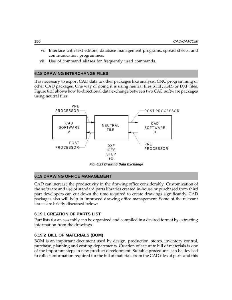
150 CAD/CAM/CIM
vi. Interface with text editors, database management programs, spread sheets, andcommunication programmes.
vii. Use of command aliases for frequently used commands.
6.18 DRAWING INTERCHANGE FILES
It is necessary to export CAD data to other packages like analysis, CNC programming orother CAD packages. One way of doing it is using neutral files STEP, IGES or DXF files.Figure 6.23 shows how bi-directional data exchange between two CAD software packagesusing neutral files.
PR E PR O C ESSO R
PO S T PR O C ESSO R
PR E PR O C ESSO R
PO S T PR O CE SSO R
etc.ST EPIG ESD XF
BSO FT WA RE
C AD
FILEN EU TR A L
ASO FT WA RE
C AD
Fig. 6.23 Drawing Data Exchange
6.19 DRAWING OFFICE MANAGEMENT
CAD can increase the productivity in the drawing office considerably. Customization ofthe software and use of standard parts libraries created in-house or purchased from thirdpart developers can cut down the time required to create drawings significantly. CADpackages also will help in improved drawing office management. Some of the relevantissues are briefly discussed below:
6.19.1 CREATION OF PARTS LISTPart lists for an assembly can be organized and compiled in a desired format by extractinginformation from the drawings.
6.19.2 BILL OF MATERIALS (BOM)BOM is an important document used by design, production, stores, inventory control,purchase, planning and costing departments. Creation of accurate bill of materials is oneof the important steps in new product development. Suitable procedures can be devisedto collect information required for the bill of materials from the CAD files of parts and this
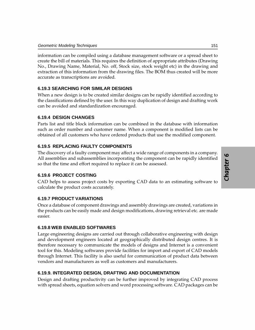
Ch
ap
ter
6C
ha
pte
r 6
Ch
ap
ter
6C
ha
pte
r 6
Ch
ap
ter
6
151Geometric Modeling Techniques
information can be compiled using a database management software or a spread sheet tocreate the bill of materials. This requires the definition of appropriate attributes (DrawingNo., Drawing Name, Material, No. off, Stock size, stock weight etc) in the drawing andextraction of this information from the drawing files. The BOM thus created will be moreaccurate as transcriptions are avoided.
6.19.3 SEARCHING FOR SIMILAR DESIGNSWhen a new design is to be created similar designs can be rapidly identified according tothe classifications defined by the user. In this way duplication of design and drafting workcan be avoided and standardization encouraged.
6.19.4 DESIGN CHANGESParts list and title block information can be combined in the database with informationsuch as order number and customer name. When a component is modified lists can beobtained of all customers who have ordered products that use the modified component.
6.19.5 REPLACING FAULTY COMPONENTSThe discovery of a faulty component may affect a wide range of components in a company.All assemblies and subassemblies incorporating the component can be rapidly identifiedso that the time and effort required to replace it can be assessed.
6.19.6 PROJECT COSTINGCAD helps to assess project costs by exporting CAD data to an estimating software tocalculate the product costs accurately.
6.19.7 PRODUCT VARIATIONSOnce a database of component drawings and assembly drawings are created, variations inthe products can be easily made and design modifications, drawing retrieval etc. are madeeasier.
6.19.8 WEB ENABLED SOFTWARESLarge engineering designs are carried out through collaborative engineering with designand development engineers located at geographically distributed design centres. It istherefore necessary to communicate the models of designs and Internet is a convenienttool for this. Modeling softwares provide facilities for import and export of CAD modelsthrough Internet. This facility is also useful for communication of product data betweenvendors and manufacturers as well as customers and manufacturers.
6.19.9. INTEGRATED DESIGN, DRAFTING AND DOCUMENTATIONDesign and drafting productivity can be further improved by integrating CAD processwith spread sheets, equation solvers and word processing software. CAD packages can be
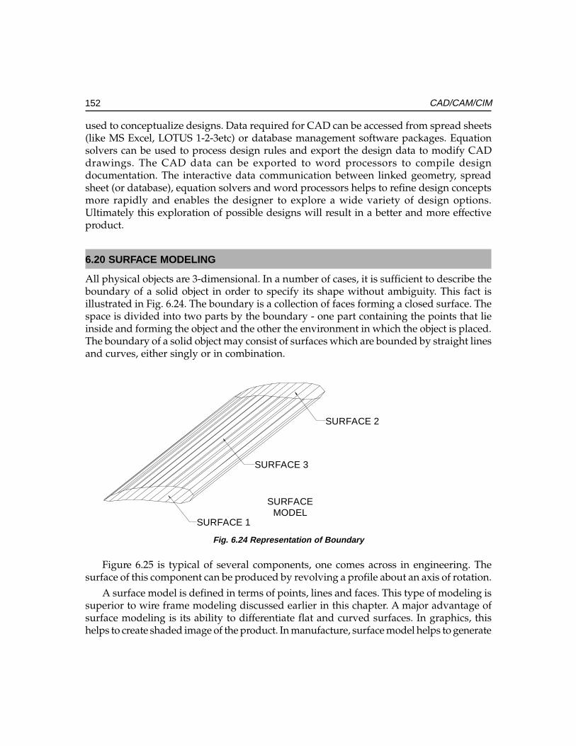
152 CAD/CAM/CIM
used to conceptualize designs. Data required for CAD can be accessed from spread sheets(like MS Excel, LOTUS 1-2-3etc) or database management software packages. Equationsolvers can be used to process design rules and export the design data to modify CADdrawings. The CAD data can be exported to word processors to compile designdocumentation. The interactive data communication between linked geometry, spreadsheet (or database), equation solvers and word processors helps to refine design conceptsmore rapidly and enables the designer to explore a wide variety of design options.Ultimately this exploration of possible designs will result in a better and more effectiveproduct.
6.20 SURFACE MODELING
All physical objects are 3-dimensional. In a number of cases, it is sufficient to describe theboundary of a solid object in order to specify its shape without ambiguity. This fact isillustrated in Fig. 6.24. The boundary is a collection of faces forming a closed surface. Thespace is divided into two parts by the boundary - one part containing the points that lieinside and forming the object and the other the environment in which the object is placed.The boundary of a solid object may consist of surfaces which are bounded by straight linesand curves, either singly or in combination.
MODELSURFACE
SURFACE 3
SURFACE 2
SURFACE 1
Fig. 6.24 Representation of Boundary
Figure 6.25 is typical of several components, one comes across in engineering. Thesurface of this component can be produced by revolving a profile about an axis of rotation.
A surface model is defined in terms of points, lines and faces. This type of modeling issuperior to wire frame modeling discussed earlier in this chapter. A major advantage ofsurface modeling is its ability to differentiate flat and curved surfaces. In graphics, thishelps to create shaded image of the product. In manufacture, surface model helps to generate
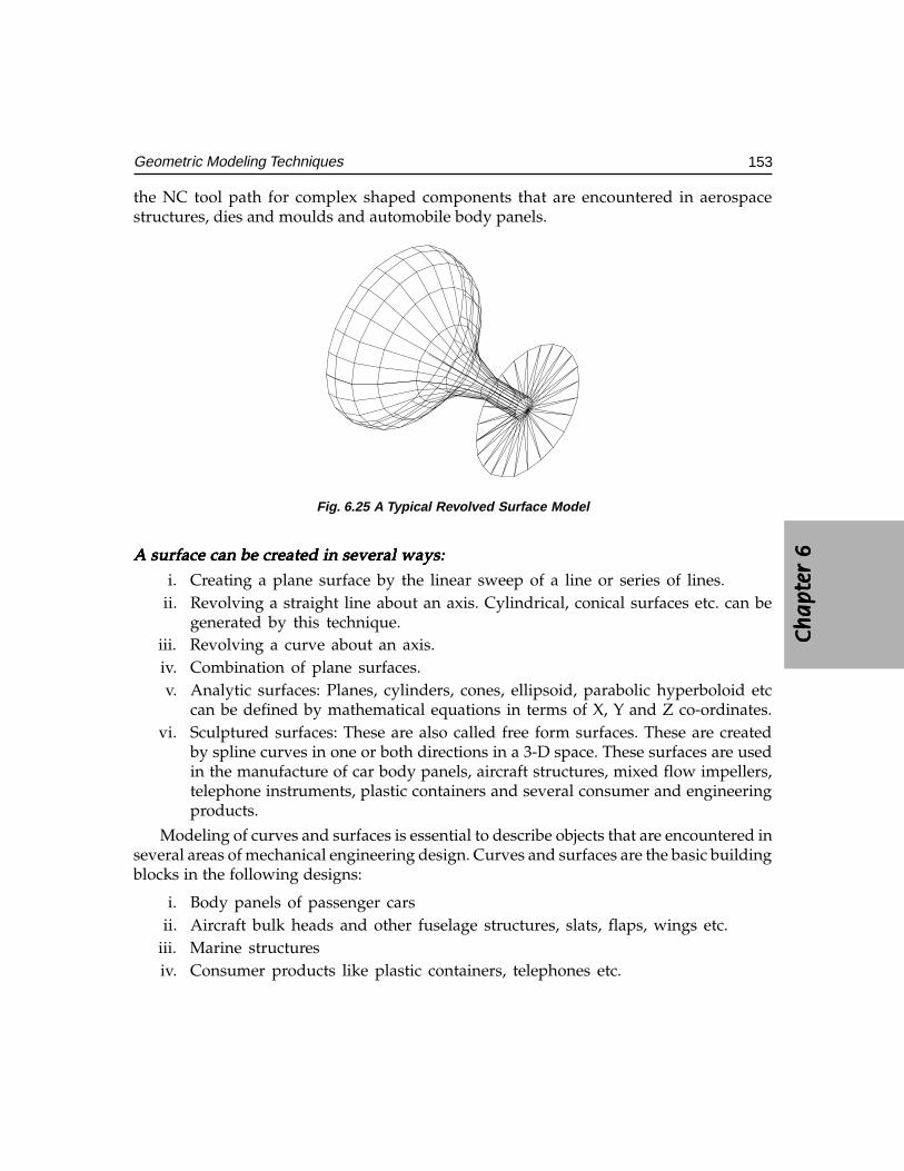
Ch
ap
ter
6C
ha
pte
r 6
Ch
ap
ter
6C
ha
pte
r 6
Ch
ap
ter
6
153Geometric Modeling Techniques
the NC tool path for complex shaped components that are encountered in aerospacestructures, dies and moulds and automobile body panels.
Fig. 6.25 A Typical Revolved Surface Model
AAAAA surface can be cr surface can be cr surface can be cr surface can be cr surface can be created in several ways:eated in several ways:eated in several ways:eated in several ways:eated in several ways:
i. Creating a plane surface by the linear sweep of a line or series of lines.ii. Revolving a straight line about an axis. Cylindrical, conical surfaces etc. can be
generated by this technique.iii. Revolving a curve about an axis.iv. Combination of plane surfaces.v. Analytic surfaces: Planes, cylinders, cones, ellipsoid, parabolic hyperboloid etc
can be defined by mathematical equations in terms of X, Y and Z co-ordinates.vi. Sculptured surfaces: These are also called free form surfaces. These are created
by spline curves in one or both directions in a 3-D space. These surfaces are usedin the manufacture of car body panels, aircraft structures, mixed flow impellers,telephone instruments, plastic containers and several consumer and engineeringproducts.
Modeling of curves and surfaces is essential to describe objects that are encountered inseveral areas of mechanical engineering design. Curves and surfaces are the basic buildingblocks in the following designs:
i. Body panels of passenger carsii. Aircraft bulk heads and other fuselage structures, slats, flaps, wings etc.
iii. Marine structuresiv. Consumer products like plastic containers, telephones etc.
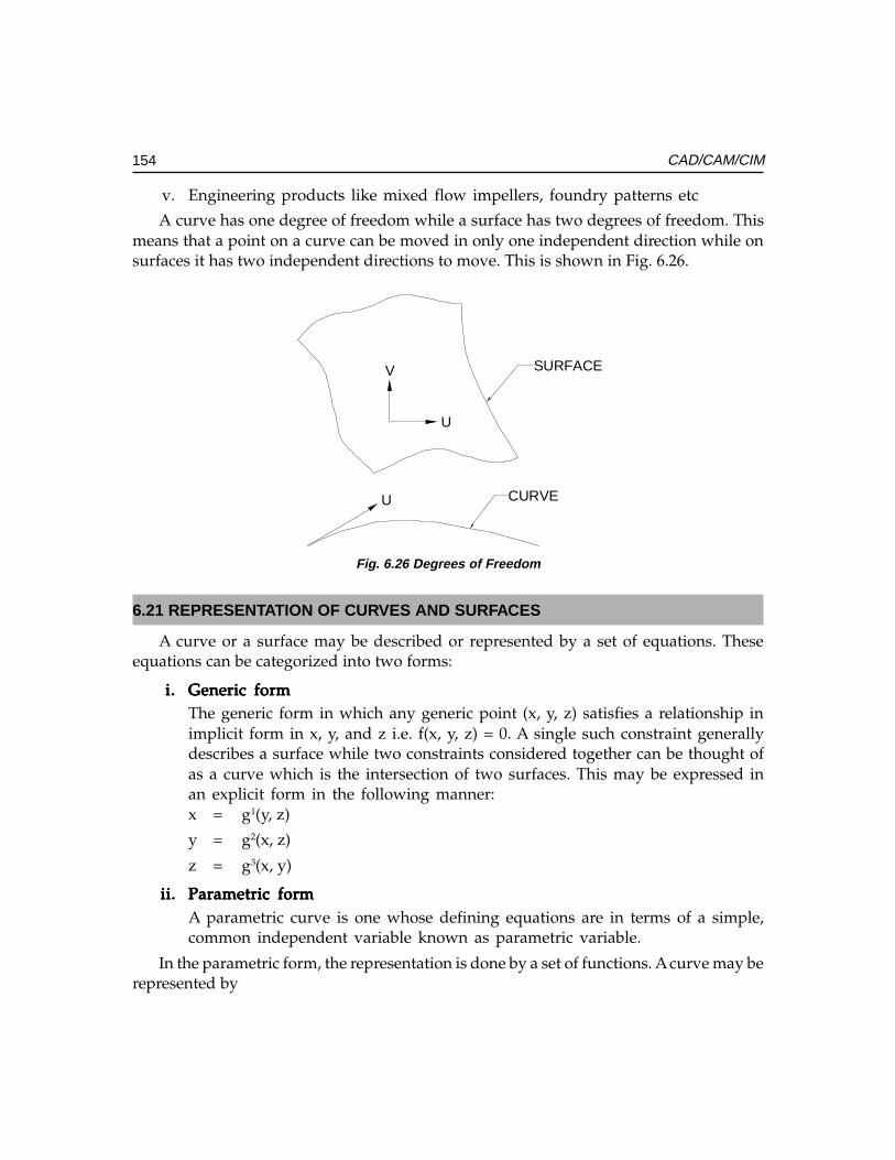
154 CAD/CAM/CIM
v. Engineering products like mixed flow impellers, foundry patterns etc
A curve has one degree of freedom while a surface has two degrees of freedom. Thismeans that a point on a curve can be moved in only one independent direction while onsurfaces it has two independent directions to move. This is shown in Fig. 6.26.
CURVEU
SURFACEV
U
Fig. 6.26 Degrees of Freedom
6.21 REPRESENTATION OF CURVES AND SURFACES
A curve or a surface may be described or represented by a set of equations. Theseequations can be categorized into two forms:
i.i.i.i.i. Generic formGeneric formGeneric formGeneric formGeneric formThe generic form in which any generic point (x, y, z) satisfies a relationship inimplicit form in x, y, and z i.e. f(x, y, z) = 0. A single such constraint generallydescribes a surface while two constraints considered together can be thought ofas a curve which is the intersection of two surfaces. This may be expressed inan explicit form in the following manner:x = g1(y, z)
y = g2(x, z)
z = g3(x, y)
ii.ii.ii.ii.ii. Parametric formParametric formParametric formParametric formParametric formA parametric curve is one whose defining equations are in terms of a simple,common independent variable known as parametric variable.
In the parametric form, the representation is done by a set of functions. A curve may berepresented by
Ch
ap
ter
6C
ha
pte
r 6
Ch
ap
ter
6C
ha
pte
r 6
Ch
ap
ter
6
155Geometric Modeling Techniques
x = x (u)y = y (u)z = z (u)
where x, y, z are co-ordinates of the points on the curve which are functions of someparameter u and the parametric variable is constrained in the interval. For example, apoint (x, y) is located at an angle θ from +X axis on a circle with centre at (0, 0) and radius= 1 can be described in parametric form as:
x = Cos θy = Sin θ
where θ is the parameter. Surfaces are described similarly for which x, y and z are functionstwo independent parameters u and v. Parametric design is very popular in computer aideddesign for a variety of reasons, which are listed below:
• Separation of variables• Each variable is treated alike• More degrees of freedom/control• Parametric equations can be transformed directly• Infinite slopes can be handled without computational breakdown• Easy to express as vectors• Amenable to plotting and digitizing• Inherently bounded
6.22 DESIGN OF CURVED SHAPES
Design of curved shapes should satisfy the following requirements:
i. It should be possible to represent the shape mathematically.ii. The modeling should involve minimum computation.
iii. It should be possible to generate a CNC program to machine the surfaces (2, 3,4 and 5 axis machining) or to prepare a mould or die to make the part (as in plasticinjection molding or casting or automobile panel pressing).
A component can be designed using the curves and shapes which can be mathematicallydescribed e.g. arc, circle, conics, ellipsoid, hyperbolic paraboloid, sphere, and cone, cylinder,linear, conical - and circular swept surfaces etc. However very often the designer startswith specifying a few points which roughly describe the shape.
Two approaches are available to designers to model curves and surfaces in such cases:interpolation and approximation. The interpolation essentially tries to pass a curve on asurface called interpolant through all these points. Approximation tries to fit a smoothercurve on surface which may be close to these points but may not actually pass througheach of them. Fig. 6.27 illustrates the difference between interpolation (a) andapproximation (b).
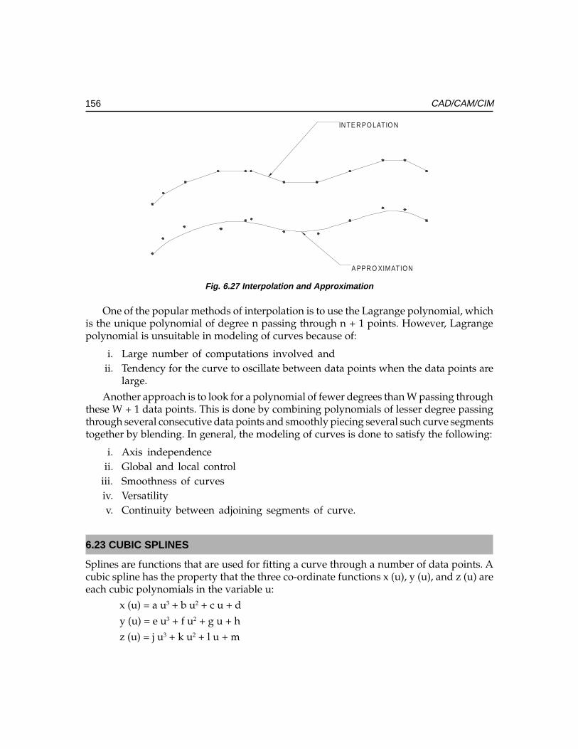
156 CAD/CAM/CIM
A PPRO XIMATION
INTE RPO LATIO N
Fig. 6.27 Interpolation and Approximation
One of the popular methods of interpolation is to use the Lagrange polynomial, whichis the unique polynomial of degree n passing through n + 1 points. However, Lagrangepolynomial is unsuitable in modeling of curves because of:
i. Large number of computations involved and ii. Tendency for the curve to oscillate between data points when the data points are
large.
Another approach is to look for a polynomial of fewer degrees than W passing throughthese W + 1 data points. This is done by combining polynomials of lesser degree passingthrough several consecutive data points and smoothly piecing several such curve segmentstogether by blending. In general, the modeling of curves is done to satisfy the following:
i. Axis independenceii. Global and local control
iii. Smoothness of curvesiv. Versatilityv. Continuity between adjoining segments of curve.
6.23 CUBIC SPLINES
Splines are functions that are used for fitting a curve through a number of data points. Acubic spline has the property that the three co-ordinate functions x (u), y (u), and z (u) areeach cubic polynomials in the variable u:
x (u) = a u3 + b u2 + c u + d
y (u) = e u3 + f u2 + g u + h
z (u) = j u3 + k u2 + l u + m
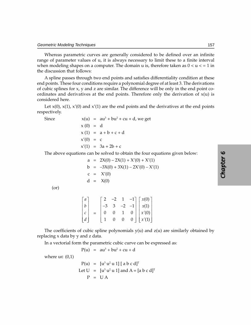
Ch
ap
ter
6C
ha
pte
r 6
Ch
ap
ter
6C
ha
pte
r 6
Ch
ap
ter
6
157Geometric Modeling Techniques
Whereas parametric curves are generally considered to be defined over an infiniterange of parameter values of u, it is always necessary to limit these to a finite intervalwhen modeling shapes on a computer. The domain u is, therefore taken as 0 < u < = 1 inthe discussion that follows:
A spline passes through two end points and satisfies differentiality condition at theseend points. These four conditions require a polynomial degree of at least 3. The derivationsof cubic splines for x, y and z are similar. The difference will be only in the end point co-ordinates and derivatives at the end points. Therefore only the derivation of x(u) isconsidered here.
Let x(0), x(1), x’(0) and x’(1) are the end points and the derivatives at the end pointsrespectively.
Since x(u) = au3 + bu2 + cu + d, we get
x (0) = d
x (1) = a + b + c + d
x’(0) = c
x’(1) = 3a + 2b + c
The above equations can be solved to obtain the four equations given below:
a = 2X(0) – 2X(1) + X’(0) + X’(1)
b = –3X(0) + 3X(1) – 2X’(0) – X’(1)
c = X’(0)
d = X(0)
(or)
a
bc
d
=
2 2 1 13 3 2 1
0 0 1 01 0 0 0
− − − − −
(0)(1)'(0)'(1)
x
xx
x
The coefficients of cubic spline polynomials y(u) and z(u) are similarly obtained byreplacing x data by y and z data.
In a vectorial form the parametric cubic curve can be expressed as:
P(u) = au3 + bu2 + cu + d
where u∈ (0,1)
P(u) = [u3 u2 u 1] [ a b c d]T
Let U = [u3 u2 u 1] and A = [a b c d]T
P = U A
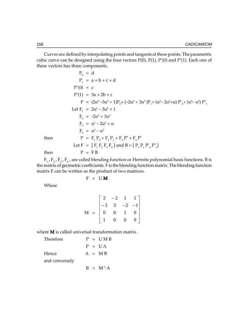
158 CAD/CAM/CIM
Curves are defined by interpolating points and tangents at these points. The parametriccubic curve can be designed using the four vectors P(0), P(1), P’(0) and P’(1). Each one ofthese vectors has three components.
P0 = d
P1 = a + b + c + d
P’(0) = c
P’(1) = 3a + 2b + c
P = (2u3 –3u2 + 1)P0+ (–2u3 + 3u2 )P1+ (u3– 2u2+u) P’0+ (u3– u2) P’1
Let F1 = 2u3 – 3u2 + 1
F2 = -2u3 + 3u2
F3 = u3 – 2u2 + u
F4 = u3 – u2
then P = F1 P0 + F2 P1 + F3 P’ + F4 P’
Let F = [ F1 F2 F3 F4 ] and B = [ P0 P1 P’0 P’1]
then P = F B
F1 , F2 , F3 , F4 , are called blending function or Hermite polynomial basis functions. B isthe matrix of geometric coefficients. F is the blending function matrix. The blending functionmatrix F can be written as the product of two matrices.
F = U MMMMM
Where
M =
−−−
−
0001
0100
1233
1122
where MMMMM is called universal transformation matrix.
Therefore P = U M B
P = U A
Hence A = M B
and conversely
B = M–1 A
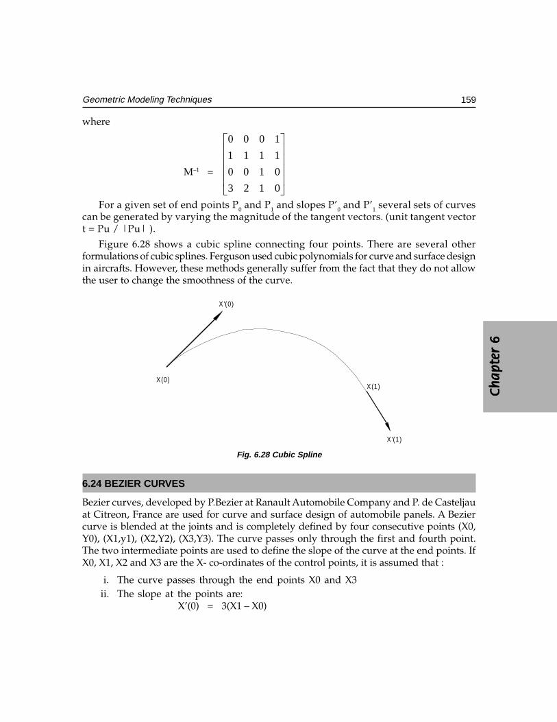
Ch
ap
ter
6C
ha
pte
r 6
Ch
ap
ter
6C
ha
pte
r 6
Ch
ap
ter
6
159Geometric Modeling Techniques
where
M–1 =
0123
0100
1111
1000
For a given set of end points P0 and P1 and slopes P’0 and P’1 several sets of curvescan be generated by varying the magnitude of the tangent vectors. (unit tangent vectort = Pu / |Pu| ).
Figure 6.28 shows a cubic spline connecting four points. There are several otherformulations of cubic splines. Ferguson used cubic polynomials for curve and surface designin aircrafts. However, these methods generally suffer from the fact that they do not allowthe user to change the smoothness of the curve.
X'(1)
X(1)
X '(0)
X(0)
Fig. 6.28 Cubic Spline
6.24 BEZIER CURVES
Bezier curves, developed by P.Bezier at Ranault Automobile Company and P. de Casteljauat Citreon, France are used for curve and surface design of automobile panels. A Beziercurve is blended at the joints and is completely defined by four consecutive points (X0,Y0), (X1,y1), (X2,Y2), (X3,Y3). The curve passes only through the first and fourth point.The two intermediate points are used to define the slope of the curve at the end points. IfX0, X1, X2 and X3 are the X- co-ordinates of the control points, it is assumed that :
i. The curve passes through the end points X0 and X3ii. The slope at the points are:
X’(0) = 3(X1 – X0)
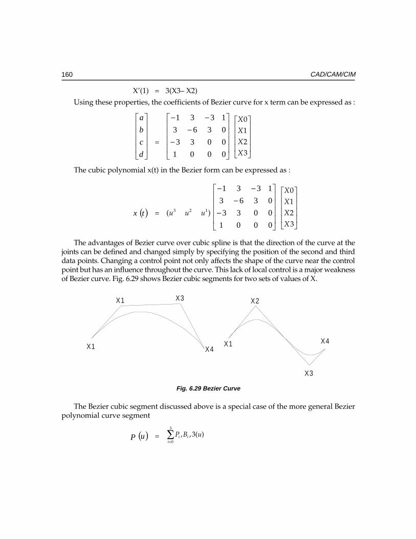
160 CAD/CAM/CIM
X’(1) = 3(X3– X2)
Using these properties, the coefficients of Bezier curve for x term can be expressed as :
d
c
b
a
=
−−
−−
0001
0033
0363
1331
X
XX
X
0123
�
�
����
�
�
����
The cubic polynomial x(t) in the Bezier form can be expressed as :
x ( )t = 3 2 1( )u u u
−−
−−
0001
0033
0363
1331
X
XX
X
0123
�
�
����
�
�
����
The advantages of Bezier curve over cubic spline is that the direction of the curve at thejoints can be defined and changed simply by specifying the position of the second and thirddata points. Changing a control point not only affects the shape of the curve near the controlpoint but has an influence throughout the curve. This lack of local control is a major weaknessof Bezier curve. Fig. 6.29 shows Bezier cubic segments for two sets of values of X.
X4
X3
X2
X1X4
X3X1
X1
Fig. 6.29 Bezier Curve
The Bezier cubic segment discussed above is a special case of the more general Bezierpolynomial curve segment
P ( )u ==∑
3
0
, , 3( )i ii
P B u
Ch
ap
ter
6C
ha
pte
r 6
Ch
ap
ter
6C
ha
pte
r 6
Ch
ap
ter
6
161Geometric Modeling Techniques
where u ∈ [0,1]
With blending functions: Bi,n (u) = C(n,i) ui (1 – u)n-i
where n is the binomial coefficient
C ( )in, =!
!
i
n−( 1)!n
and p(u) are the control points and there are n+1 of them defining the vertices of thecharacteristic polygon.
6.25 βββββ-SPLINES
This form of cubic segments uses a third set of basis functions different from the typesdiscussed earlier. A cubic β-spline curve is a special case of spline curve. The equation forthis curve can be written as:
P (u) = ∑n
i=1 P i N i, k (u)
u ∈ [0, (n– k + 2)]
This generates what is known as piecewise polynomial. The N(u) blending functionsare defined recursively as :
N (u) = 1 if ti < u < ti+1
= 0 otherwise
N ( )u =( ) ( ) ( ) ( )
tt
uKNut
tt
uKNtu
−−+
−−
11
,,
The resulting parametric polynomials are of degree (k - 1). The t are called knot values.For an open curve there are
ti = 0 if i < k
ti = i – k +1 if k ≤ i ≤ n i ∈ [0, n + k]
ti = n – k + 2 if i > n
The blending functions confine the effects of a control point movement to the immediatelocale. Thus the curve change shape is local and not global as it is for Bezier curves.
x(u) = (1 u u2 u3 ) 1/6
−−−
−
1331
0363
0303
0141
+
−
−
1
1
2
i
i
i
i
x
x
x
x
162 CAD/CAM/CIM
When the control points are distinct, this curve is continuous in slope and in curvaturebetween successive segments but it does not pass through any of the intermediate controlpoints. The cubic β-spline has the advantage that the control points may be moved withoutaffecting slope and curvature continuity and only four spans of the overall curve will beaffected by the change. Moreover, by allowing two control points to coincide it is possibleto create a curvature discontinuity. A slope discontinuity, similarly, can be introduced bychoosing three successive control points to be coincident.
It is possible to represent complex curve shapes by considering composite curvesconstructed from individual segments, in the case of cubic spline, Bezier and B-splinetechniques.
6.26 NURBS AND βββββ-SPLINES
Two important surface representation schemes exist that extend the control of shape beyondmovement of control vertices. These are NURBS (Non Uniform Rational β-Splines) and β-splines. In the case of NURBS a local vertex is extended to a four dimensional co-ordinate,the extra parameter being a weight that allows a subtle form of control which is differentin effect to moving a control vertex. In the simplest form of β-spline control two globalparameters (bias and tension) are introduced which affect the whole curve.
6.26.1 NURBSA non-uniform β-spline curve is defined on a knot vector where the interior knot spansare not equal. A rational β-spline is defined by a set of four dimensional control points.
P = (Wi Xi , Wi Yi , Wi Zi , Wi )
The perspective map of such a curve in three dimensional space is called a rationalβ-spline curve.
P(u) = H ,0
[ ( )]n w
i i ki
PN u=∑
P(u) = ( )
∑
=
n
iKi
Wi uNPH
0,
= ( ) ( )∑∑==
n
iKi
n
iuKii uWWP
0,
0,
= ( )∑=
n
iKii uRP
0,
Rational β- splines have the same analytical and geometric properties as non-rationalβ- splines.
Ch
ap
ter
6C
ha
pte
r 6
Ch
ap
ter
6C
ha
pte
r 6
Ch
ap
ter
6
163Geometric Modeling Techniques
Wi associated with each control point is called a weight and can be viewed as an extrashape parameter. Wi affects the curve only locally and can be interpreted geometrically asa coupling factor. The curve is pulled towards a control point if W increases.
6.26.2 βββββ- SPLINESβ- splines are obtained from β-splines by introducing two new degrees of freedom: biasand tension. These can be applied uniformly or non-uniformly.
6.27 REPRESENTATION OF SURFACES
A surface can be defined as the locus of points which satisfy a constraint equation in theform of F(X, Y, Z) = 0. In parametric form a surface may be represented as
x = X (u, v)
y = Y (u, v)
z = Z (u, v)
where X, Y and Z are suitable functions of two parameters u and v. For example, theparametric representation of the surface of a sphere whose centre is at the origin of co-ordinates and of radius R is
x = X (θ, φ) = R sin φ cos θy = Y (θ, φ) = R sin φ sin θz = Z (θ, φ) = R cos φ
6.28 DESIGN OF SURFACES
The design of surfaces may be based on quadrics like ellipsoid, hyperboloid, cone,hyperbolic cylinder, parabolic cylinder, elliptic cylinder and elliptic paraboloid. A surfacemay be generated by sweeping a pattern curve along a spline curve. The swept surfacemay also be linear, conical linear or circular swept surface.
6.29 PARAMETRIC DESIGN OF SURFACES
Parametric surfaces may be defined in one of the following methods:
i. In terms of points of data (positions, tangents, normals)ii. In terms of data on a number of space curves lying in these surfaces.
The resulting surface will either interpolate or approximate the data. Surfaces arenormally designed in patches, each patch corresponding to a rectangular domain in u-vspace. A surface patch defined in terms of point data will usually be based on a rectangular
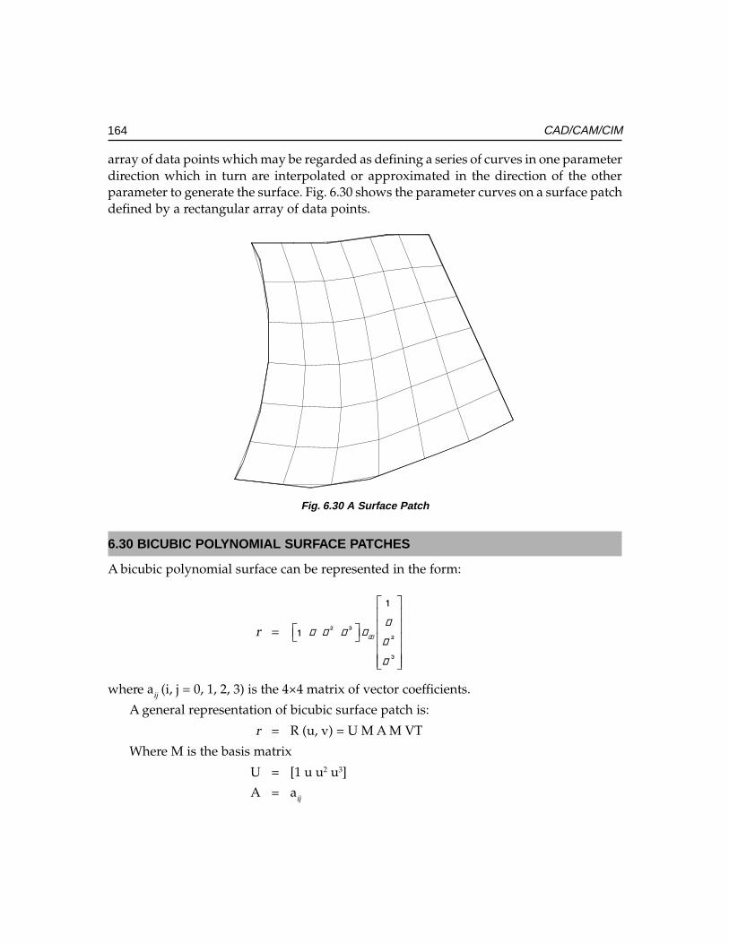
164 CAD/CAM/CIM
array of data points which may be regarded as defining a series of curves in one parameterdirection which in turn are interpolated or approximated in the direction of the otherparameter to generate the surface. Fig. 6.30 shows the parameter curves on a surface patchdefined by a rectangular array of data points.
Fig. 6.30 A Surface Patch
6.30 BICUBIC POLYNOMIAL SURFACE PATCHES
A bicubic polynomial surface can be represented in the form:
r =
� �
�
�
�
���
�
� � � �
�
�
where aij (i, j = 0, 1, 2, 3) is the 4×4 matrix of vector coefficients.
A general representation of bicubic surface patch is:
r = R (u, v) = U M A M VT
Where M is the basis matrix
U = [1 u u2 u3]
A = aij
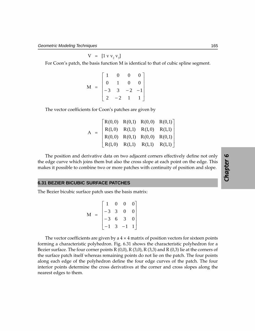
Ch
ap
ter
6C
ha
pte
r 6
Ch
ap
ter
6C
ha
pte
r 6
Ch
ap
ter
6
165Geometric Modeling Techniques
V = [1 v v2 v3]
For Coon’s patch, the basis function M is identical to that of cubic spline segment.
M =
−−−−1122
1233
0010
0001
The vector coefficients for Coon’s patches are given by
A =
R(0,0) R(0,1) R(0,0) R(0,1)
R(1,0) R(1,1) R(1,0) R(1,1)
R(0,0) R(0,1) R(0,0) R(0,1)
R(1,0) R(1,1) R(1,1) R(1,1)
The position and derivative data on two adjacent corners effectively define not onlythe edge curve which joins them but also the cross slope at each point on the edge. Thismakes it possible to combine two or more patches with continuity of position and slope.
6.31 BEZIER BICUBIC SURFACE PATCHES
The Bezier bicubic surface patch uses the basis matrix:
M =
−−−−
1131
0363
0033
0001
The vector coefficients are given by a 4 × 4 matrix of position vectors for sixteen pointsforming a characteristic polyhedron. Fig. 6.31 shows the characteristic polyhedron for aBezier surface. The four corner points R (0,0), R (3,0), R (3,3) and R (0,3) lie at the corners ofthe surface patch itself whereas remaining points do not lie on the patch. The four pointsalong each edge of the polyhedron define the four edge curves of the patch. The fourinterior points determine the cross derivatives at the corner and cross slopes along thenearest edges to them.
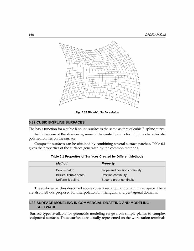
166 CAD/CAM/CIM
Fig. 6.31 Bi-cubic Surface Patch
6.32 CUBIC B-SPLINE SURFACES
The basis function for a cubic B-spline surface is the same as that of cubic B-spline curve.
As in the case of B-spline curve, none of the control points forming the characteristicpolyhedron lies on the surface.
Composite surfaces can be obtained by combining several surface patches. Table 6.1gives the properties of the surfaces generated by the common methods.
Table 6.1 Properties of Surfaces Created by Different Methods
Method Property
Coon’s patch Slope and position continuity
Bezier Bicubic patch Position continuity
Uniform B-spline Second order continuity
The surfaces patches described above cover a rectangular domain in u-v space. Thereare also methods proposed for interpolation on triangular and pentagonal domains.
6.33 SURFACE MODELING IN COMMERCIAL DRAFTING AND MODELINGSOFTWARE
Surface types available for geometric modeling range from simple planes to complexsculptured surfaces. These surfaces are usually represented on the workstation terminals
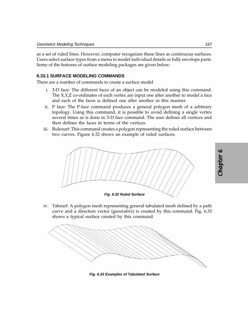
Ch
ap
ter
6C
ha
pte
r 6
Ch
ap
ter
6C
ha
pte
r 6
Ch
ap
ter
6
167Geometric Modeling Techniques
as a set of ruled lines. However, computer recognizes these lines as continuous surfaces.Users select surface types from a menu to model individual details or fully envelope parts.Some of the features of surface modeling packages are given below:
6.33.1 SURFACE MODELING COMMANDSThere are a number of commands to create a surface model
i. 3-D face: The different faces of an object can be modeled using this command.The X,Y,Z co-ordinates of each vertex are input one after another to model a faceand each of the faces is defined one after another in this manner.
ii. P face: The P-face command produces a general polygon mesh of a arbitrarytopology. Using this command, it is possible to avoid defining a single vertexseveral times as is done in 3-D face command. The user defines all vertices andthen defines the faces in terms of the vertices.
iii. Rulesurf: This command creates a polygon representing the ruled surface betweentwo curves. Figure 6.32 shows an example of ruled surfaces.
Fig. 6.32 Ruled Surface
iv. Tabsurf: A polygon mesh representing general tabulated mesh defined by a pathcurve and a direction vector (generatrix) is created by this command. Fig. 6.33shows a typical surface created by this command.
Fig. 6.33 Examples of Tabulated Surface
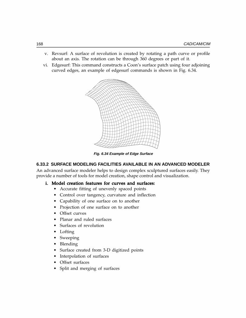
168 CAD/CAM/CIM
v. Revsurf: A surface of revolution is created by rotating a path curve or profileabout an axis. The rotation can be through 360 degrees or part of it.
vi. Edgesurf: This command constructs a Coon’s surface patch using four adjoiningcurved edges, an example of edgesurf commands is shown in Fig. 6.34.
Fig. 6.34 Example of Edge Surface
6.33.2 SURFACE MODELING FACILITIES AVAILABLE IN AN ADVANCED MODELERAn advanced surface modeler helps to design complex sculptured surfaces easily. Theyprovide a number of tools for model creation, shape control and visualization.
i.i.i.i.i. Model crModel crModel crModel crModel creation featureation featureation featureation featureation features for curves and surfaces:es for curves and surfaces:es for curves and surfaces:es for curves and surfaces:es for curves and surfaces:• Accurate fitting of unevenly spaced points• Control over tangency, curvature and inflection• Capability of one surface on to another• Projection of one surface on to another• Offset curves• Planar and ruled surfaces• Surfaces of revolution• Lofting• Sweeping• Blending• Surface created from 3-D digitized points• Interpolation of surfaces• Offset surfaces• Split and merging of surfaces
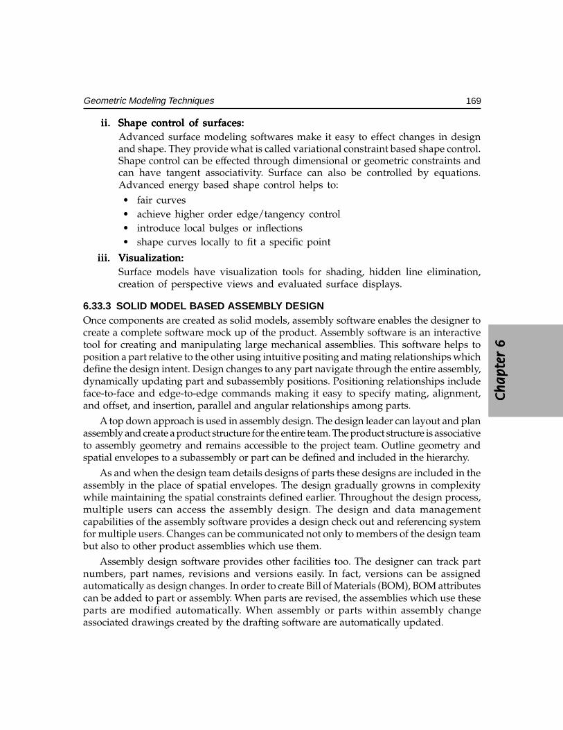
Ch
ap
ter
6C
ha
pte
r 6
Ch
ap
ter
6C
ha
pte
r 6
Ch
ap
ter
6
169Geometric Modeling Techniques
ii.ii.ii.ii.ii. Shape contrShape contrShape contrShape contrShape control of surfaces:ol of surfaces:ol of surfaces:ol of surfaces:ol of surfaces:Advanced surface modeling softwares make it easy to effect changes in designand shape. They provide what is called variational constraint based shape control.Shape control can be effected through dimensional or geometric constraints andcan have tangent associativity. Surface can also be controlled by equations.Advanced energy based shape control helps to:• fair curves• achieve higher order edge/tangency control• introduce local bulges or inflections• shape curves locally to fit a specific point
iii.iii.iii.iii.iii. VVVVVisualization:isualization:isualization:isualization:isualization:Surface models have visualization tools for shading, hidden line elimination,creation of perspective views and evaluated surface displays.
6.33.3 SOLID MODEL BASED ASSEMBLY DESIGNOnce components are created as solid models, assembly software enables the designer tocreate a complete software mock up of the product. Assembly software is an interactivetool for creating and manipulating large mechanical assemblies. This software helps toposition a part relative to the other using intuitive positing and mating relationships whichdefine the design intent. Design changes to any part navigate through the entire assembly,dynamically updating part and subassembly positions. Positioning relationships includeface-to-face and edge-to-edge commands making it easy to specify mating, alignment,and offset, and insertion, parallel and angular relationships among parts.
A top down approach is used in assembly design. The design leader can layout and planassembly and create a product structure for the entire team. The product structure is associativeto assembly geometry and remains accessible to the project team. Outline geometry andspatial envelopes to a subassembly or part can be defined and included in the hierarchy.
As and when the design team details designs of parts these designs are included in theassembly in the place of spatial envelopes. The design gradually growns in complexitywhile maintaining the spatial constraints defined earlier. Throughout the design process,multiple users can access the assembly design. The design and data managementcapabilities of the assembly software provides a design check out and referencing systemfor multiple users. Changes can be communicated not only to members of the design teambut also to other product assemblies which use them.
Assembly design software provides other facilities too. The designer can track partnumbers, part names, revisions and versions easily. In fact, versions can be assignedautomatically as design changes. In order to create Bill of Materials (BOM), BOM attributescan be added to part or assembly. When parts are revised, the assemblies which use theseparts are modified automatically. When assembly or parts within assembly changeassociated drawings created by the drafting software are automatically updated.
170 CAD/CAM/CIM
Assembly design software is a powerful tool for design evaluation. Since parts aredesigned in solid models the design can carry out checks for interference between matingparts and subassemblies. It is also possible to animate kinematic assemblies to evaluatehow mechanisms work. Since variational geometry is used, the designer can vary thedimensions of the links to study the impact of design changes and articulate the mechanismin real time.
Assembly level mass and inertial properties can also be calculated. The renderingcapabilities available in the modeling package enable true to life presentation of theassembly to management, marketing, manufacturing, purchase and other downstreamusers for review. Their feedback will be useful to avoid costly design changes at the end ofproduct development cycle.
6.33.4 SOLID MODEL BASED DRAFTINGThe drafting process creates production drawings. When solid model based design isfollowed, the production drawings can be generated from the solid model itself. Some draftingsystems allow either a single user or dual user. In the single user mode, the entire design/drafting job is done by a single designer by creating a design with solid or assembly modelerand documenting that model using the drafting module. Bi-directional associativity helpsto make changes to the solid model by incorporating a change in the detail drawing. Thedual user approach is suitable for organizations where design and drafting tasks are carriedout by separate persons. This mode of work enables the draftsman to begin his work evenbefore the designer completes his design. Concurrent associativity allows the drawing to beupdated while maintaining design change control with the design engineer. Drafting moduleprovides the following additional facilities also:
(i) Set up and create associative single or multiple cross sections through parts withautomatic cross hatching
(ii) Associative detail views can be added(iii) Make first angle or third angle projections, isometric, auxiliary or true projections(iv) Multiple view of one or more drawings can be placed on one drawing or multiple
drawings(v) Automatic removal or display of hidden line by dashed lines
(vi) Border, title block or the necessary drawing format can be added(vii) Different layers for different parts of the drawing can be specified.
Many solid modeling packages provide exhaustive symbol libraries or facilities to createsymbols which expedite detailing of drawings. A variety of dimensioning techniques areavailable. Dimensioning can be automatic or a dynamic navigation style with userinteraction can be adopted. In the latter, as the draftsman traverses the drawing, thegeometry entities are highlighted. Appropriate icons are displayed next to the curser thatrepresent the dimensions. These dimensions can be added simply by picking with thecursor. Dimensioning supports ANSI, ISO, DIN, BIS and JIS. Geometric dimensioning and
Ch
ap
ter
6C
ha
pte
r 6
Ch
ap
ter
6C
ha
pte
r 6
Ch
ap
ter
6
171Geometric Modeling Techniques
tolerancing methods are also available in the package. Provision for adding text orannotations in different languages is also available. Another facility available is theassociative cross hatching facility with ability to recognize internal holes and islands.
Another feature of a drafting module is the dynamic Bill of Materials that automaticallyupdates when changes are made to the drawing. This ensures that BOM accurately reflectsthe data of the drawing.
In addition to the above the drafting module includes integrated drawing managementcapabilities. Some of these capabilities are listed below:
(i) Lists the solid model associated with the part drawing(ii) Lists all drawings associated with a model
(iii) Searches for a drawing by name, number or the draftsman(iv) Stores the drawings in libraries(v) Retrieve drawings
(vi) Tracks drawing stage (in-design, check, released etc)(vii) Tracks revisions and versions
(viii) Compiles total time spent on a drawing(ix) Tracks drawings read from STEP, IGES and DXF files(x) Creates of engineering change order
(xi) Provides project configurations
Drafting modules associated with solid modeling packages can also be used for standalone drafting. The features of a drafting package are discussed in a subsequent section inthis chapter.
6.33.5 SOLID MODEL BASED MECHANISM DESIGNSolid model based kinematic analysis can be used to determine complex motions ofmechanisms. A mechanical design software is used for this purpose. Mechanism modelsare defined directly on the assembly model geometry. Rigid models are defined directlyon the assembly model geometry. Rigid bodies are automatically understood and jointsand constraints are defined simply by selecting appropriate locations on the assembly.Motions of mechanisms and loads are defined using a forms based user interface and canbe defined by mathematical expressions or sketches. All solid geometry and inertiaproperties can be accessed from the assembly design. Mechanism design capabilities includethe following :
Joint definitionJoint definitionJoint definitionJoint definitionJoint definitionRevolve
Universal
Planar
172 CAD/CAM/CIM
General (screw, rack & pinion)
Ball
Translational
Cylindrical
ConstraintsConstraintsConstraintsConstraintsConstraintsGround
Spring/damper
Coupler
Gears
MotionsMotionsMotionsMotionsMotionsRotational about revolute or cylindrical joint
Translation along a cylindrical or transitional joint
LoadsLoadsLoadsLoadsLoadsRotational and translational forces
Gravity
Torque
Velocity
Acceleration
FunctionsFunctionsFunctionsFunctionsFunctionsAbility to display several simultaneous functions
Functions defined by mathematical expressions
Transformations to manipulate functions
Geometry checking to determine the validity of mechanisms
Once joints, constraints and functions have been defined the mechanism can be solvedusing an internal solver. Some of the capabilities of a typical mechanism solver are given below:
(i) Analysis of open and closed loop mechanisms(ii) Shaded animation
(iii) Determination of position, velocity and acceleration of all bodies(iv) Automatic solid model based interference checking(v) Joint, inertia and spring forces are automatically calculated
(vi) Relative position, velocity and acceleration between any two arbitrary points canbe obtained
(vii) Plotting facilities are available
Ch
ap
ter
6C
ha
pte
r 6
Ch
ap
ter
6C
ha
pte
r 6
Ch
ap
ter
6
173Geometric Modeling Techniques
This kinematic analysis module as an add on to solid modeling packages also willhave facility to preprocess data to be used in an advanced kinematic analysis package likeADAMS or DADS.
6.33.6 FINITE ELEMENT MODELING FROM SOLID MODELSOptimization of designs require detailed analysis to determine stresses, deflection, naturalfrequencies, mode shapes, temperature distribution, heat flow rates etc. Finite elementtechnique is used to carry out these analysis is to create a finite element model. The solidmodel geometry can be used directly to create the FE model.
Automatic mesh generation and application of loads and boundary conditions canalso be carried out while creating the finite element model.
It is often necessary to modify design geometry to create an effective finite elementmodel. Automatic mesh generation can be done either through free meshing or adaptivemeshing. A comprehensive library of finite elements are available in the software. Theelements will be linear or parabolic. Shell, solid, beam, rod, spring, damper, mass and gapare some of the elements available for the purpose of modeling. A FE modeling softwareprovides extensive capabilities to define loading and boundary conditions to correctlysimulate the environment that a part will be subjected in operation.
Loads can be:Loads can be:Loads can be:Loads can be:Loads can be:
• Structural loads• Heat transfer loads
Physical and material properties can be obtained from the material database of thesolid model. Facilities for mode checking and model optimization are also available.
The optimized model can be solved by any one of the analysis package like ANSYS,NISA, ABAQUS or NASTRAN. Finite element modeling, analysis, simulation andoptimization are discussed in the next chapter.
6.33.7 GENERATIVE CNC MACHINING BASED ON SOLID MODELINGThe geometry of solid models can serve as the basis for generating CNC codes formanufacturing the component. Solid modeling based generative machining softwarehelps to:
(i) evolve stock model(ii) capture manufacturing planning
(iii) design the tooling(iv) develop feature driven machining programs
Solid modeling based machining software encompasses the complete machiningenvironment. The tool paths generated by it avoid grouping of parts, avoid collision withclamps and optimize motion.
174 CAD/CAM/CIM
Thus solid modeling technique helps in
(i) conceptualize the design(ii) provide interface to analysis
(iii) generate NC tool paths
A number of software packages are available now for modeling. Important amongthem are:
AUTOCAD
IDEAS
PRO/ENGINEER
UNIGRAPHICS
CADDS V
CATIA
CADAM
IEMS
SOLID WORKS
SOLID EDGEIRON CAD
6.34 THE CONCEPTUAL DESIGN PROCESS
Traditionally designers used to make 2-D or 3-D sketches as starting point of shapedesigns. From these sketches, models in materials like wood, clay, sheet metal or poly-urethane foam will be made. These models were then displayed to public or groups ofinterested persons like management or customers to obtain the customer preferences orreactions or feed back. The final design shape is then arrived at by altering the modelscreated incorporating engineering and manufacturing feedback. This process used totake considerable time and constituted a significant portion of product developmentcycle time.
With the emphasis on time compression in product development, the accent today isin using the computer itself for conceptual design. Once the shape design is completed,the model data could be transferred to the solid modeling software to complete the designanalysis and optimization. The software used for conceptual design is also called computeraided industrial design (CAID) package. CAID package is a conceptual front end of theproduct development process and are specifically designed to stimulate creativity byproviding a wide variety of design options. This tool can quickly create and modify theshape, form and surface qualities of 3D models. A CAID package will have photorealisticrendering and lighting capabilities. Several software packages offer the CAID capabilities.Prominent among them are:
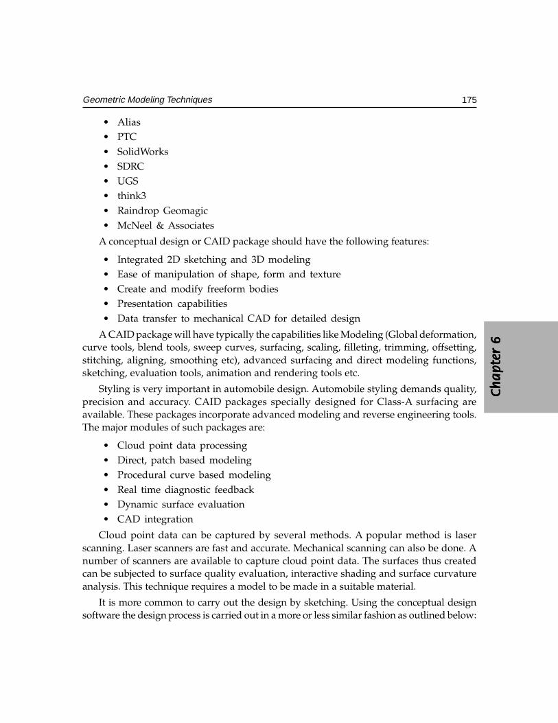
Ch
ap
ter
6C
ha
pte
r 6
Ch
ap
ter
6C
ha
pte
r 6
Ch
ap
ter
6
175Geometric Modeling Techniques
• Alias• PTC• SolidWorks• SDRC• UGS• think3• Raindrop Geomagic• McNeel & Associates
A conceptual design or CAID package should have the following features:
• Integrated 2D sketching and 3D modeling• Ease of manipulation of shape, form and texture• Create and modify freeform bodies• Presentation capabilities• Data transfer to mechanical CAD for detailed design
A CAID package will have typically the capabilities like Modeling (Global deformation,curve tools, blend tools, sweep curves, surfacing, scaling, filleting, trimming, offsetting,stitching, aligning, smoothing etc), advanced surfacing and direct modeling functions,sketching, evaluation tools, animation and rendering tools etc.
Styling is very important in automobile design. Automobile styling demands quality,precision and accuracy. CAID packages specially designed for Class-A surfacing areavailable. These packages incorporate advanced modeling and reverse engineering tools.The major modules of such packages are:
• Cloud point data processing• Direct, patch based modeling• Procedural curve based modeling• Real time diagnostic feedback• Dynamic surface evaluation• CAD integration
Cloud point data can be captured by several methods. A popular method is laserscanning. Laser scanners are fast and accurate. Mechanical scanning can also be done. Anumber of scanners are available to capture cloud point data. The surfaces thus createdcan be subjected to surface quality evaluation, interactive shading and surface curvatureanalysis. This technique requires a model to be made in a suitable material.
It is more common to carry out the design by sketching. Using the conceptual designsoftware the design process is carried out in a more or less similar fashion as outlined below:
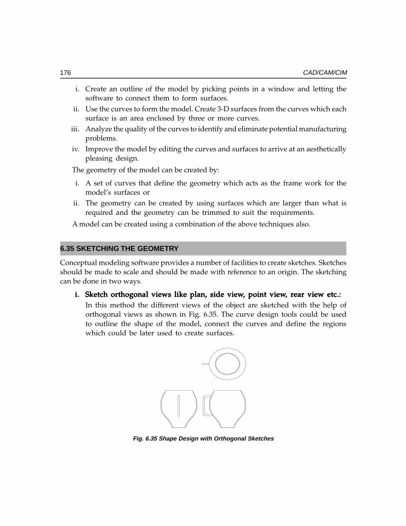
176 CAD/CAM/CIM
i. Create an outline of the model by picking points in a window and letting thesoftware to connect them to form surfaces.
ii. Use the curves to form the model. Create 3-D surfaces from the curves which eachsurface is an area enclosed by three or more curves.
iii. Analyze the quality of the curves to identify and eliminate potential manufacturingproblems.
iv. Improve the model by editing the curves and surfaces to arrive at an aestheticallypleasing design.
The geometry of the model can be created by:
i. A set of curves that define the geometry which acts as the frame work for themodel’s surfaces or
ii. The geometry can be created by using surfaces which are larger than what isrequired and the geometry can be trimmed to suit the requirements.
A model can be created using a combination of the above techniques also.
6.35 SKETCHING THE GEOMETRY
Conceptual modeling software provides a number of facilities to create sketches. Sketchesshould be made to scale and should be made with reference to an origin. The sketchingcan be done in two ways.
i.i.i.i.i. Sketch orthogonal views like plan, side viewSketch orthogonal views like plan, side viewSketch orthogonal views like plan, side viewSketch orthogonal views like plan, side viewSketch orthogonal views like plan, side view, point view, point view, point view, point view, point view, r, r, r, r, rear view etc.:ear view etc.:ear view etc.:ear view etc.:ear view etc.:In this method the different views of the object are sketched with the help oforthogonal views as shown in Fig. 6.35. The curve design tools could be usedto outline the shape of the model, connect the curves and define the regionswhich could be later used to create surfaces.
Fig. 6.35 Shape Design with Orthogonal Sketches
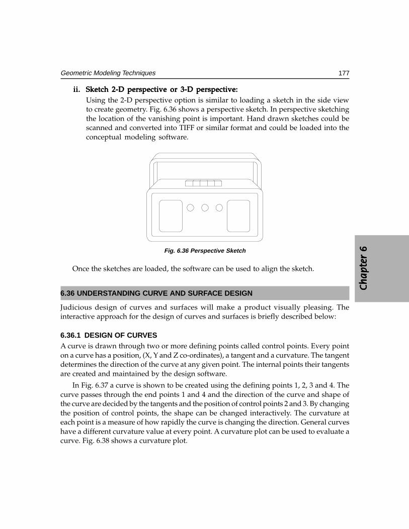
Ch
ap
ter
6C
ha
pte
r 6
Ch
ap
ter
6C
ha
pte
r 6
Ch
ap
ter
6
177Geometric Modeling Techniques
ii.ii.ii.ii.ii. Sketch 2-D perspective or 3-D perspective:Sketch 2-D perspective or 3-D perspective:Sketch 2-D perspective or 3-D perspective:Sketch 2-D perspective or 3-D perspective:Sketch 2-D perspective or 3-D perspective:Using the 2-D perspective option is similar to loading a sketch in the side viewto create geometry. Fig. 6.36 shows a perspective sketch. In perspective sketchingthe location of the vanishing point is important. Hand drawn sketches could bescanned and converted into TIFF or similar format and could be loaded into theconceptual modeling software.
Fig. 6.36 Perspective Sketch
Once the sketches are loaded, the software can be used to align the sketch.
6.36 UNDERSTANDING CURVE AND SURFACE DESIGN
Judicious design of curves and surfaces will make a product visually pleasing. Theinteractive approach for the design of curves and surfaces is briefly described below:
6.36.1 DESIGN OF CURVESA curve is drawn through two or more defining points called control points. Every pointon a curve has a position, (X, Y and Z co-ordinates), a tangent and a curvature. The tangentdetermines the direction of the curve at any given point. The internal points their tangentsare created and maintained by the design software.
In Fig. 6.37 a curve is shown to be created using the defining points 1, 2, 3 and 4. Thecurve passes through the end points 1 and 4 and the direction of the curve and shape ofthe curve are decided by the tangents and the position of control points 2 and 3. By changingthe position of control points, the shape can be changed interactively. The curvature ateach point is a measure of how rapidly the curve is changing the direction. General curveshave a different curvature value at every point. A curvature plot can be used to evaluate acurve. Fig. 6.38 shows a curvature plot.
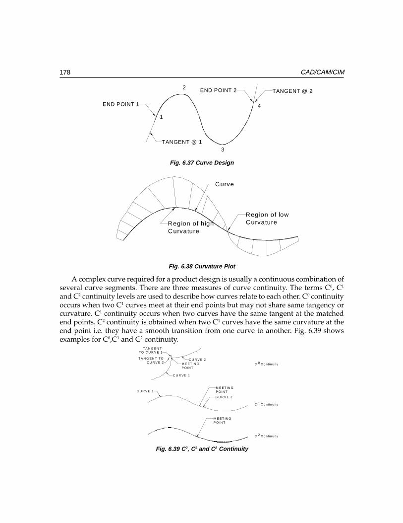
178 CAD/CAM/CIM
1
2
3
4END POINT 1
END POINT 2
TANGENT @ 1
TANGENT @ 2
Fig. 6.37 Curve Design
Region of lowCurvatureRegion of high
Curvature
Curve
Fig. 6.38 Curvature Plot
A complex curve required for a product design is usually a continuous combination ofseveral curve segments. There are three measures of curve continuity. The terms C0, C1
and C2 continuity levels are used to describe how curves relate to each other. C0 continuityoccurs when two C1 curves meet at their end points but may not share same tangency orcurvature. C1 continuity occurs when two curves have the same tangent at the matchedend points. C2 continuity is obtained when two C1 curves have the same curvature at theend point i.e. they have a smooth transition from one curve to another. Fig. 6.39 showsexamples for C0,C1 and C2 continuity.
C U R V E 1
C U R V E 2
M E ET IN GP O IN T
M E ET IN GP O IN T
C C o n tin u ity
C C o n tin u ity
C C o n tin u ity
0
1
2
C U R V E 2
C U R V E 1
M E ET IN GP O IN T
TA N G EN TTO C U R V E 1
TA N G EN T TOC U R V E 2
Fig. 6.39 C0, C1 and C2 Continuity
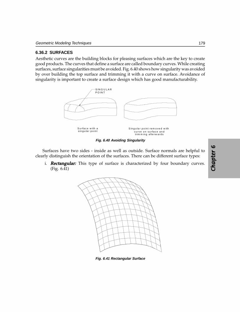
Ch
ap
ter
6C
ha
pte
r 6
Ch
ap
ter
6C
ha
pte
r 6
Ch
ap
ter
6
179Geometric Modeling Techniques
6.36.2 SURFACESAesthetic curves are the building blocks for pleasing surfaces which are the key to creategood products. The curves that define a surface are called boundary curves. While creatingsurfaces, surface singularities must be avoided. Fig. 6.40 shows how singularity was avoidedby over building the top surface and trimming it with a curve on surface. Avoidance ofsingularity is important to create a surface design which has good manufacturability.
S IN G U L A RP O IN T
S u rfa c e w ith as in g u la r p o in t
S in g u la r p o in t re m o v e d w ith c u rv e o n s u rfa c e a n dtr im m in g a f te rw a rd s
Fig. 6.40 Avoiding Singularity
Surfaces have two sides - inside as well as outside. Surface normals are helpful toclearly distinguish the orientation of the surfaces. There can be different surface types:
i. Rectangular: Rectangular: Rectangular: Rectangular: Rectangular: This type of surface is characterized by four boundary curves.(Fig. 6.41)
Fig. 6.41 Rectangular Surface
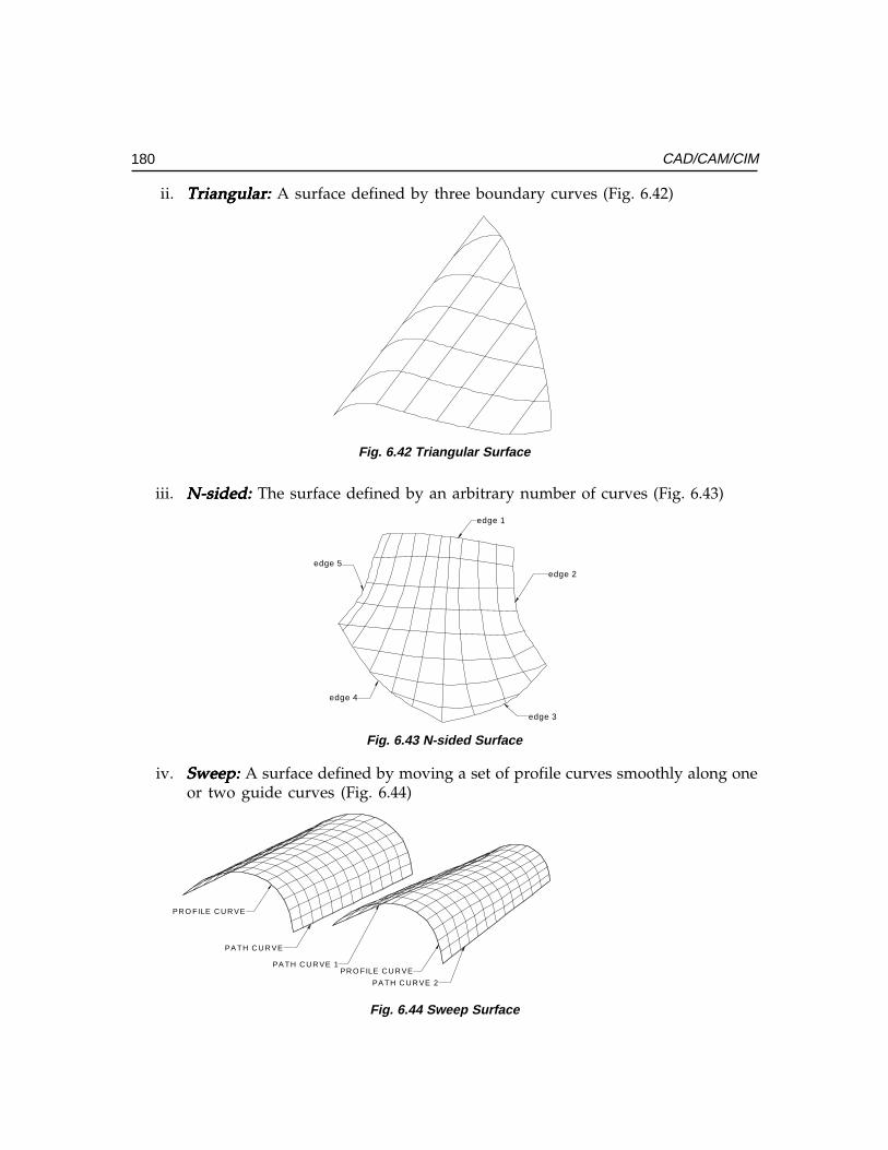
180 CAD/CAM/CIM
ii. Triangular: Triangular: Triangular: Triangular: Triangular: A surface defined by three boundary curves (Fig. 6.42)
Fig. 6.42 Triangular Surface
iii. N-sided: N-sided: N-sided: N-sided: N-sided: The surface defined by an arbitrary number of curves (Fig. 6.43)
edge 1
edge 2
edge 3
edge 4
edge 5
Fig. 6.43 N-sided Surface
iv. Sweep: Sweep: Sweep: Sweep: Sweep: A surface defined by moving a set of profile curves smoothly along oneor two guide curves (Fig. 6.44)
PR O FILE C U R VE
PA TH C U R VE
PA TH C U R VE 1
PA TH C U R VE 2
PR O FILE C U R VE
Fig. 6.44 Sweep Surface
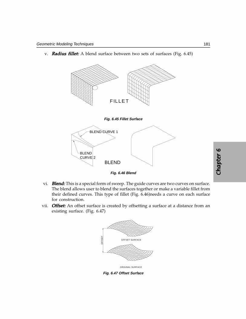
Ch
ap
ter
6C
ha
pte
r 6
Ch
ap
ter
6C
ha
pte
r 6
Ch
ap
ter
6
181Geometric Modeling Techniques
v. Radius fillet:Radius fillet:Radius fillet:Radius fillet:Radius fillet: A blend surface between two sets of surfaces (Fig. 6.45)
FILLE T
Fig. 6.45 Fillet Surface
BLEND
BLEND CURVE 1
BLENDCURVE 2
Fig. 6.46 Blend
vi. Blend:Blend:Blend:Blend:Blend: This is a special form of sweep. The guide curves are two curves on surface.The blend allows user to blend the surfaces together or make a variable fillet fromtheir defined curves. This type of fillet (Fig. 6.46)needs a curve on each surfacefor construction.
vii. Offset:Offset:Offset:Offset:Offset: An offset surface is created by offsetting a surface at a distance from anexisting surface. (Fig. 6.47)
ORIGINAL SURFACE
OFFSET SURFACE
OF
FS
ET
Fig. 6.47 Offset Surface
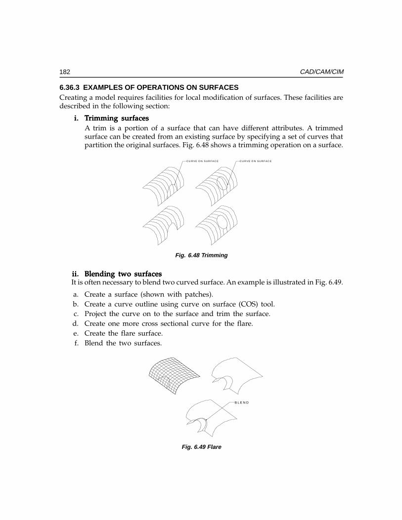
182 CAD/CAM/CIM
6.36.3 EXAMPLES OF OPERATIONS ON SURFACESCreating a model requires facilities for local modification of surfaces. These facilities aredescribed in the following section:
i.i.i.i.i. TTTTTrimming surfacesrimming surfacesrimming surfacesrimming surfacesrimming surfacesA trim is a portion of a surface that can have different attributes. A trimmedsurface can be created from an existing surface by specifying a set of curves thatpartition the original surfaces. Fig. 6.48 shows a trimming operation on a surface.
C U R V E O N S U R FA C E C U R V E O N S U R FA C E
Fig. 6.48 Trimming
ii.ii.ii.ii.ii. Blending two surfacesBlending two surfacesBlending two surfacesBlending two surfacesBlending two surfacesIt is often necessary to blend two curved surface. An example is illustrated in Fig. 6.49.
a. Create a surface (shown with patches).b. Create a curve outline using curve on surface (COS) tool.c. Project the curve on to the surface and trim the surface.d. Create one more cross sectional curve for the flare.e. Create the flare surface.f. Blend the two surfaces.
B L E N D
Fig. 6.49 Flare
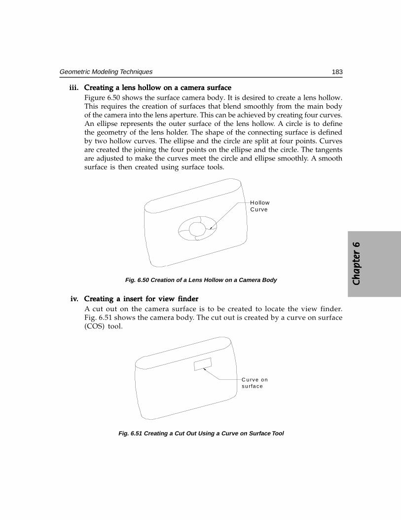
Ch
ap
ter
6C
ha
pte
r 6
Ch
ap
ter
6C
ha
pte
r 6
Ch
ap
ter
6
183Geometric Modeling Techniques
iii.iii.iii.iii.iii. Creating a lens hollow on a camera surfaceCreating a lens hollow on a camera surfaceCreating a lens hollow on a camera surfaceCreating a lens hollow on a camera surfaceCreating a lens hollow on a camera surfaceFigure 6.50 shows the surface camera body. It is desired to create a lens hollow.This requires the creation of surfaces that blend smoothly from the main bodyof the camera into the lens aperture. This can be achieved by creating four curves.An ellipse represents the outer surface of the lens hollow. A circle is to definethe geometry of the lens holder. The shape of the connecting surface is definedby two hollow curves. The ellipse and the circle are split at four points. Curvesare created the joining the four points on the ellipse and the circle. The tangentsare adjusted to make the curves meet the circle and ellipse smoothly. A smoothsurface is then created using surface tools.
HollowCurve
Fig. 6.50 Creation of a Lens Hollow on a Camera Body
iviviviviv..... CrCrCrCrCreating a insert for view findereating a insert for view findereating a insert for view findereating a insert for view findereating a insert for view finderA cut out on the camera surface is to be created to locate the view finder.Fig. 6.51 shows the camera body. The cut out is created by a curve on surface(COS) tool.
C u rve o nsu rface
Fig. 6.51 Creating a Cut Out Using a Curve on Surface Tool
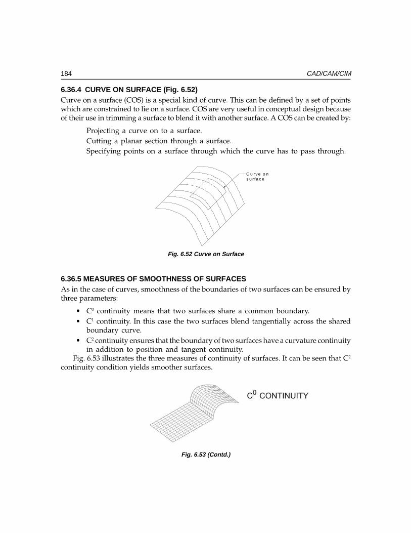
184 CAD/CAM/CIM
6.36.4 CURVE ON SURFACE (Fig. 6.52)Curve on a surface (COS) is a special kind of curve. This can be defined by a set of pointswhich are constrained to lie on a surface. COS are very useful in conceptual design becauseof their use in trimming a surface to blend it with another surface. A COS can be created by:
Projecting a curve on to a surface.Cutting a planar section through a surface.Specifying points on a surface through which the curve has to pass through.
C u rv e o ns u r fa c e
Fig. 6.52 Curve on Surface
6.36.5 MEASURES OF SMOOTHNESS OF SURFACESAs in the case of curves, smoothness of the boundaries of two surfaces can be ensured bythree parameters:
• C0 continuity means that two surfaces share a common boundary.• C1 continuity. In this case the two surfaces blend tangentially across the shared
boundary curve.• C2 continuity ensures that the boundary of two surfaces have a curvature continuity
in addition to position and tangent continuity.Fig. 6.53 illustrates the three measures of continuity of surfaces. It can be seen that C2
continuity condition yields smoother surfaces.
Fig. 6.53 (Contd.)
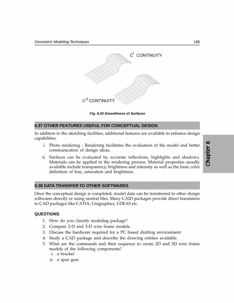
Ch
ap
ter
6C
ha
pte
r 6
Ch
ap
ter
6C
ha
pte
r 6
Ch
ap
ter
6
185Geometric Modeling Techniques
Fig. 6.53 Smoothness of Surfaces
6.37 OTHER FEATURES USEFUL FOR CONCEPTUAL DESIGN
In addition to the sketching facilities, additional features are available to enhance designcapabilities:
i. Photo rendering - Rendering facilitates the evaluation of the model and bettercommunication of design ideas,
ii. Surfaces can be evaluated by accurate reflections, highlights and shadows.Materials can be applied in the rendering process. Material properties usuallyavailable include transparency, brightness and intensity as well as the basic colordefinition of hue, saturation and brightness.
6.38 DATA TRANSFER TO OTHER SOFTWARES
Once the conceptual design is completed, model data can be transferred to other designsoftwares directly or using neutral files. Many CAID packages provide direct translatorsto CAD packages like CATIA, Unigraphics, I-DEAS etc.
QUESTIONS
1. How do you classify modeling package?2. Compare 2-D and 3-D wire frame models.3. Discuss the hardware required for a PC based drafting environment4. Study a CAD package and describe the drawing entities available.5. What are the commands and their sequence to create 2D and 3D wire frame
models of the following components?i. a bracket
ii. a spur gear
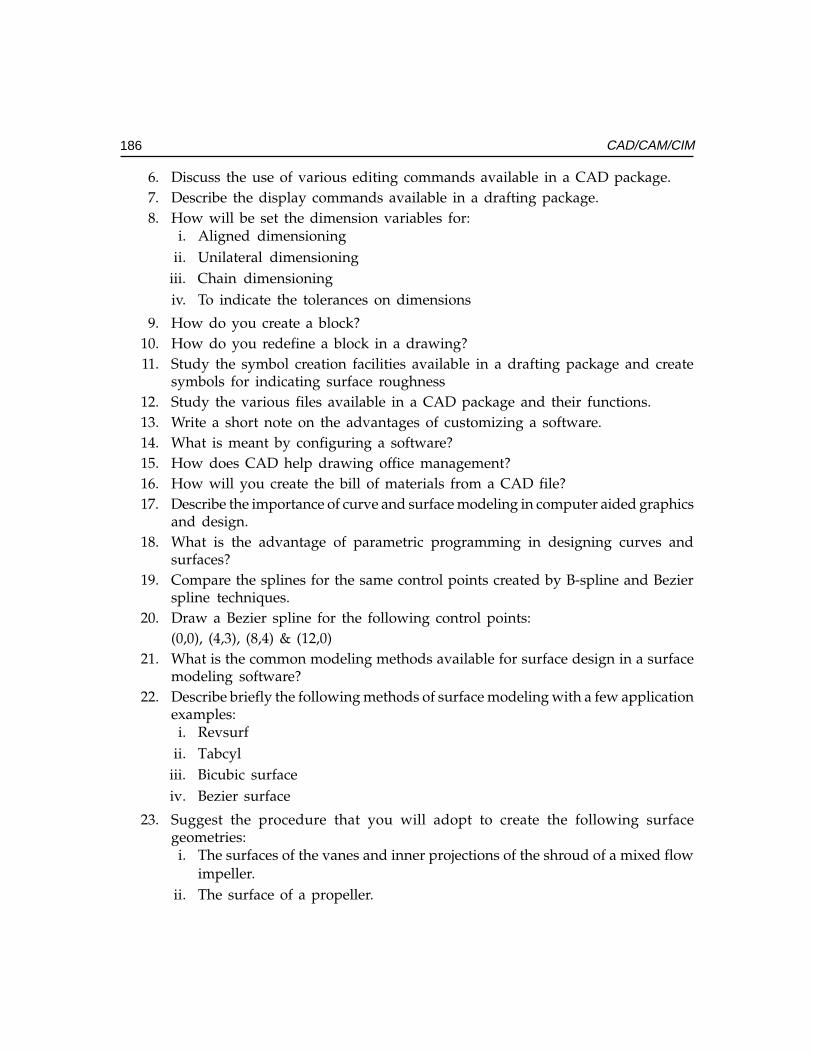
186 CAD/CAM/CIM
6. Discuss the use of various editing commands available in a CAD package.7. Describe the display commands available in a drafting package.8. How will be set the dimension variables for:
i. Aligned dimensioningii. Unilateral dimensioning
iii. Chain dimensioningiv. To indicate the tolerances on dimensions
9. How do you create a block?10. How do you redefine a block in a drawing?11. Study the symbol creation facilities available in a drafting package and create
symbols for indicating surface roughness12. Study the various files available in a CAD package and their functions.13. Write a short note on the advantages of customizing a software.14. What is meant by configuring a software?15. How does CAD help drawing office management?16. How will you create the bill of materials from a CAD file?17. Describe the importance of curve and surface modeling in computer aided graphics
and design.18. What is the advantage of parametric programming in designing curves and
surfaces?19. Compare the splines for the same control points created by B-spline and Bezier
spline techniques.20. Draw a Bezier spline for the following control points:
(0,0), (4,3), (8,4) & (12,0)21. What is the common modeling methods available for surface design in a surface
modeling software?22. Describe briefly the following methods of surface modeling with a few application
examples:i. Revsurf
ii. Tabcyliii. Bicubic surfaceiv. Bezier surface
23. Suggest the procedure that you will adopt to create the following surfacegeometries:i. The surfaces of the vanes and inner projections of the shroud of a mixed flow
impeller.ii. The surface of a propeller.
Ch
ap
ter
6C
ha
pte
r 6
Ch
ap
ter
6C
ha
pte
r 6
Ch
ap
ter
6
187Geometric Modeling Techniques
24. Exercisesi Create an assembly of a reduction gearbox and prepare geometric models of
individual components.ii Create a surface model of a mouse.
iii Create a solid model of a bracket and extract plan, elevation, end view anda sectional view, with dimensions.
iv Create a frame type structure in C.I and extract mass properties.
25. Create a solid model and generate a STEP file. Write a program to extract all flatsurfaces and holes.i. Study typical consumer durable products like electric iron, coffee percolator,
water heater etc. and analyze the impact of shape design on their salesappeal.
ii. Study the shape of a passenger car and analyze how the blending of varioussurfaces of body panels is done.
iii. Compare the measures of continuity of curves and surfaces.
26. Study typical consumer durable products like electric iron, coffee percolator,water heater etc. and analyze the impact of shape design on their sales appeal.
27. Study the shape of a passenger car and analyze how the blending of varioussurfaces of body panels is done.
28. Compare the measures of continuity of curves and surfaces.
PROJECT
1. Obtain a cloud of points on the surface of an impeller blade and create a smoothsurface, using CAD software.
2. Create the surface model of a product of your choice.(a toy car, a blender, desktop grinder, shampoo bottle, a two-in-one transistor cumtape recorder, head lamp of a passenger car, etc.).

This pageintentionally left
blank
���������������
���������
���� ����������
�������
Finite element modeling (FEM) and finite element analysis (FEA) are used today in severalfields of engineering and technology. Finite element analysis is one of the powerful techniquesfor not only design but also for manufacturing applications. Therefore, FEA has an importantrole in CIM. This chapter gives a brief account of the technique and surveys some applicationsof this technique. A few examples from design and a brief review of applications tomanufacturing simulation are given in this chapter.
7.1 INTRODUCTION
Traditional approach to design analysis involves the application of classical or analyticaltechniques. This approach has the following limitations:
i. Stresses and strains are obtained only at macro level. This may result ininappropriate deployment of materials. Micro level information is necessary tooptimally allocate material to heavily stressed parts.
ii. Adequate information will not be available on critically stressed parts of thecomponents.
iii. It may be necessary to make several simplifications and assumptions to designcomplex components and systems, if design analysis is carried out in theconventional manner.
iv. Manual design is time consuming and prone to errors.v. Design optimization is tedious and time consuming.
FEA is a convenient tool to analyze simple as well as complex structures. The use offinite element analysis is not restricted to mechanical engineering systems alone. FEA findsextensive application in electrical engineering, electronics engineering, micro electromechanical systems, biomedical engineering etc. In manufacturing, FEA is used in simulationand optimization of manufacturing processes like casting, machining, plastic molding,forging, metal forming, heat treatment, welding etc. Structural, dynamic, thermal, magneticpotential and fluid flow problems can be handled with ease and accuracy using FEA.
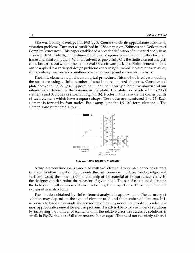
190 CAD/CAM/CIM
FEA was initially developed in 1943 by R. Courant to obtain approximate solution tovibration problems. Turner et al published in 1956 a paper on “Stiffness and Deflection ofComplex Structures”. This paper established a broader definition of numerical analysis asa basis of FEA. Initially, finite element analysis programs were mainly written for mainframe and mini computers. With the advent of powerful PC’s, the finite element analysiscould be carried out with the help of several FEA software packages. Finite element methodcan be applied to a variety of design problems concerning automobiles, airplanes, missiles,ships, railway coaches and countless other engineering and consumer products.
The finite element method is a numerical procedure. This method involves modelingthe structure using a finite number of small interconnected elements. Consider theplate shown in Fig. 7.1 (a). Suppose that it is acted upon by a force P as shown and ourinterest is to determine the stresses in the plate. The plate is discretized into 20 ofelements and 33 nodes as shown in Fig. 7.1 (b). Nodes in this case are the corner pointsof each element which have a square shape. The nodes are numbered 1 to 33. Eachelement is formed by four nodes. For example, nodes 1,9,10,2 form element 1. Theelements are numbered 1 to 20.
1
2
3
4
5
6
7
8
9
10
11
12
13
14
15
16
17
18
19
20
21
22
23
24
25
26
27
28
29
30
31
32
33
1
2
3
4
5
6
7
8
9
10
11
12
13
14
15
16
17
18
19
20
PART TO BEANALYZED
FINITE ELEMENTMESH
1,2,3..........NODES
1 2 3 ELEMENTS
P
(a) (b)
A
Fig. 7.1 Finite Element Modeling
A displacement function is associated with each element. Every interconnected elementis linked to other neighboring elements through common interfaces (nodes, edges andsurfaces). Using the stress- strain relationship of the material of the part under analysis,the designer can determine the behavior of given node. The set of equations describingthe behavior of all nodes results in a set of algebraic equations. These equations areexpressed in matrix form.
The solution obtained by finite element analysis is approximate. The accuracy ofsolution may depend on the type of element used and the number of elements. It isnecessary to have a thorough understanding of the physics of the problem to select themost appropriate element for a given problem. It is advisable to try a number of solutionsby increasing the number of elements until the relative error in successive solutions issmall. In Fig. 7.1 the size of all elements are shown equal. This need not be strictly adhered
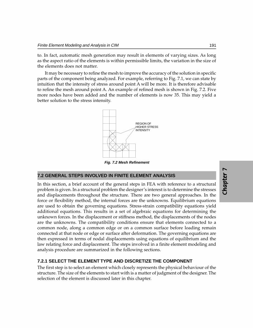
Ch
ap
ter
7C
ha
pte
r 7
Ch
ap
ter
7C
ha
pte
r 7
Ch
ap
ter
7
191Finite Element Modeling and Analysis in CIM
to. In fact, automatic mesh generation may result in elements of varying sizes. As longas the aspect ratio of the elements is within permissible limits, the variation in the size ofthe elements does not matter.
It may be necessary to refine the mesh to improve the accuracy of the solution in specificparts of the component being analyzed. For example, referring to Fig. 7.1, we can state byintuition that the intensity of stress around point A will be more. It is therefore advisableto refine the mesh around point A. An example of refined mesh is shown in Fig. 7.2. Fivemore nodes have been added and the number of elements is now 35. This may yield abetter solution to the stress intensity.
REGION OFHIGHER STRESSINTENSITY
Fig. 7.2 Mesh Refinement
7.2 GENERAL STEPS INVOLVED IN FINITE ELEMENT ANALYSIS
In this section, a brief account of the general steps in FEA with reference to a structuralproblem is given. In a structural problem the designer’s interest is to determine the stressesand displacements throughout the structure. There are two general approaches. In theforce or flexibility method, the internal forces are the unknowns. Equilibrium equationsare used to obtain the governing equations. Stress-strain compatibility equations yieldadditional equations. This results in a set of algebraic equations for determining theunknown forces. In the displacement or stiffness method, the displacements of the nodesare the unknowns. The compatibility conditions ensure that elements connected to acommon node, along a common edge or on a common surface before loading remainconnected at that node or edge or surface after deformation. The governing equations arethen expressed in terms of nodal displacements using equations of equilibrium and thelaw relating force and displacement. The steps involved in a finite element modeling andanalysis procedure are summarized in the following sections.
7.2.1 SELECT THE ELEMENT TYPE AND DISCRETIZE THE COMPONENTThe first step is to select an element which closely represents the physical behaviour of thestructure. The size of the elements to start with is a matter of judgment of the designer. Theselection of the element is discussed later in this chapter.
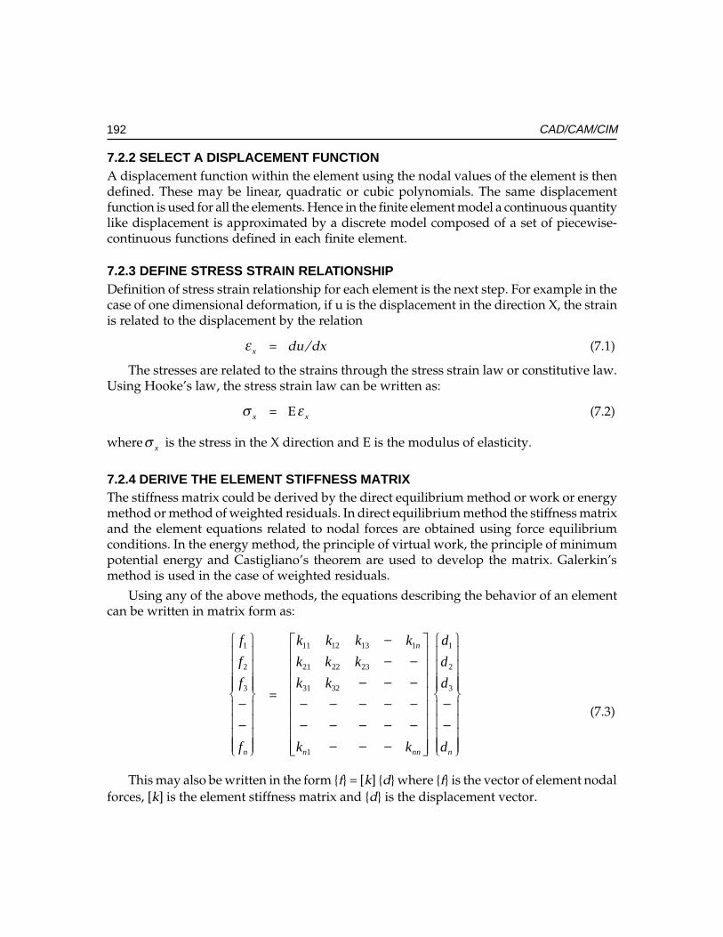
192 CAD/CAM/CIM
7.2.2 SELECT A DISPLACEMENT FUNCTIONA displacement function within the element using the nodal values of the element is thendefined. These may be linear, quadratic or cubic polynomials. The same displacementfunction is used for all the elements. Hence in the finite element model a continuous quantitylike displacement is approximated by a discrete model composed of a set of piecewise-continuous functions defined in each finite element.
7.2.3 DEFINE STRESS STRAIN RELATIONSHIPDefinition of stress strain relationship for each element is the next step. For example in thecase of one dimensional deformation, if u is the displacement in the direction X, the strainis related to the displacement by the relation
xε = du/dx (7.1)
The stresses are related to the strains through the stress strain law or constitutive law.Using Hooke’s law, the stress strain law can be written as:
xσ = E xε (7.2)
where xσ is the stress in the X direction and E is the modulus of elasticity.
7.2.4 DERIVE THE ELEMENT STIFFNESS MATRIXThe stiffness matrix could be derived by the direct equilibrium method or work or energymethod or method of weighted residuals. In direct equilibrium method the stiffness matrixand the element equations related to nodal forces are obtained using force equilibriumconditions. In the energy method, the principle of virtual work, the principle of minimumpotential energy and Castigliano’s theorem are used to develop the matrix. Galerkin’smethod is used in the case of weighted residuals.
Using any of the above methods, the equations describing the behavior of an elementcan be written in matrix form as:
−−
nf
f
f
f
3
2
1
=
−−−−−−−−−−−−−−−−−−
−
nnn
n
kk
kk
kkk
kkkk
1
3231
232221
1131211
−−
nd
d
d
d
3
2
1
(7.3)
This may also be written in the form {f} = [k] {d} where {f} is the vector of element nodalforces, [k] is the element stiffness matrix and {d} is the displacement vector.
Ch
ap
ter
7C
ha
pte
r 7
Ch
ap
ter
7C
ha
pte
r 7
Ch
ap
ter
7
193Finite Element Modeling and Analysis in CIM
7.2.5 ASSEMBLE GLOBAL STIFFNESS MATRIXThe individual element stiffness matrices are then assembled to obtain the global stiffnessmatrix of the whole component being analyzed. The global stiffness matrix is written as:
[F] = [K]{d} (7.4)where [F] vector of global nodal forces, [K] is the global stiffness matrix and{ }d is thevector of unknown displacements.
7.2.6 SOLVE TO OBTAIN NODAL DISPLACEMENTSPre-multiplying both sides of Eq. 7.4 by the inverse of stiffness matrix we will obtain thesolution for the displacements.
7.2.7 SOLVE FOR ELEMENT STRAINS AND STRESSESStrains can be computed from the displacements. Once the strain is known the stress canbe calculated using Hooke’s law. Principal stresses, shear stresses, von Mises stresses(equivalent stress) etc. could be computed depending on the interest of the designer.
The finite element analysis does not stop here. The results are to be interpreted withthe aid of nodal data as well as post processed plots of the results. The analysis could berepeated by changing the number of nodes and elements to check if there is convergencebetween successive analysis results. In case specific areas of the component are to beanalyzed in detail to improve the accuracy, the number of nodes and elements in theportions of interest could be increased and analysis repeated. Sub structuring techniquecould also be adopted. In case the designer is looking for an optimum solution, the analysiscould be carried out after defining the objective criterion.
7.3 TYPES OF ANALYSIS
Depending upon the type of design problem handled, the finite element analysis can beclassified into several types.
7.3.1 STRUCTURAL ANALYSIS (STATIC AND DYNAMIC ANALYSIS)If the analysis involves only the calculation of stresses and deflections in a mechanicalcomponent, the analysis is called structural analysis. In this case, the designer creates afinite element model of the component. The structural model thus created can be used topredict the behavior of the real structure, under the action of external forces. The result isusually obtained in terms of nodal deflection and stress. If the loads do not vary with time,this analysis is called static analysis. When the loads vary with time, the analysis is calleddynamic analysis. A dynamic force will induce velocities and accelerations that will produceappreciable variations in displacements and stresses depending on the frequency ofexcitation and the natural frequency of the component analyzed. If the displacement,velocity or acceleration is computed against time, the response is called transient responseanalysis or steady state analysis depending on the problem.
194 CAD/CAM/CIM
Another type of dynamic analysis is the computation of the model’s natural frequenciesof vibration and associated mode shapes. For example, such a type of analysis can be used tostudy the response of an automobile traveling over a rough terrain at a particular speed. Thedynamic force may create uncomfortable vibrations of the whole structure or the vehicle aswell as individual parts like the steering wheel or door panel. In the case of a machine toolstructure, it is necessary to avoid high amplitudes of vibration of the machine tool, tool,work piece and fixture system to ensure good surface finish on work pieces and better toollife. When designing such components, it is important to avoid natural frequencies, whichmight get excited in the course of normal operation. Analysis can also be carried out at thedesign stage to assess the risks to arrive at a robust design.
7.3.2 LINEAR AND NON-LINEAR ANALYSISIf the properties of the structure, such as stiffness remain constant during the entire analysis,the analysis is called linear. If these properties vary, the analysis is non-linear. Such variationcan be due to large displacements in the structure (geometric non-linearity), large scaleyielding in the material (material non-linearity) or changes in boundary conditions.
7.3.3 THERMAL ANALYSISFinite element analysis can be used for several design and analysis problems involvingthermal stresses, thermal displacement, heat flow, temperature distribution etc.
7.3.4 FLUID FLOW ANALYSISFinite element analysis can solve several types of fluid flow problems. Fluid flow is veryimportant in many engineering design problems involving aerospace, automobile, chemicalengineering, power generation, heating, ventilation, air conditioning, biomedicalengineering, combustion, oil and gas, ship design, microfluidics, micropumps etc. Tillrecently, designers had to resort to experimental studies to verify design assumptions. Theimprovement in the processing power of personal computers and availability of verypowerful programs has made reasonably accurate numerical solutions possible. This fieldhas become very specialized of late and is called computational fluid dynamics (CFD).CFD is now capable of predicting the performance of new designs before they aremanufactured.
7.3.5 FIELD ANALYSIS (ELECTRICAL, MAGNETIC, ELECTROMAGNETIC ANDELECTROSTATIC)
Problems in the analysis of magnetic flux and acoustics can be solved by finite elementanalysis. Example of magnetic analysis is the study of the distribution of magnetic flux inthe stator of an electric motor. Field analysis can be applied to the design of radio frequencydevices, microwave devices, solenoids, magnets etc.
7.3.6 MEMS DESIGNThe design of micro-electromechanical systems is a specialized field of analysis.
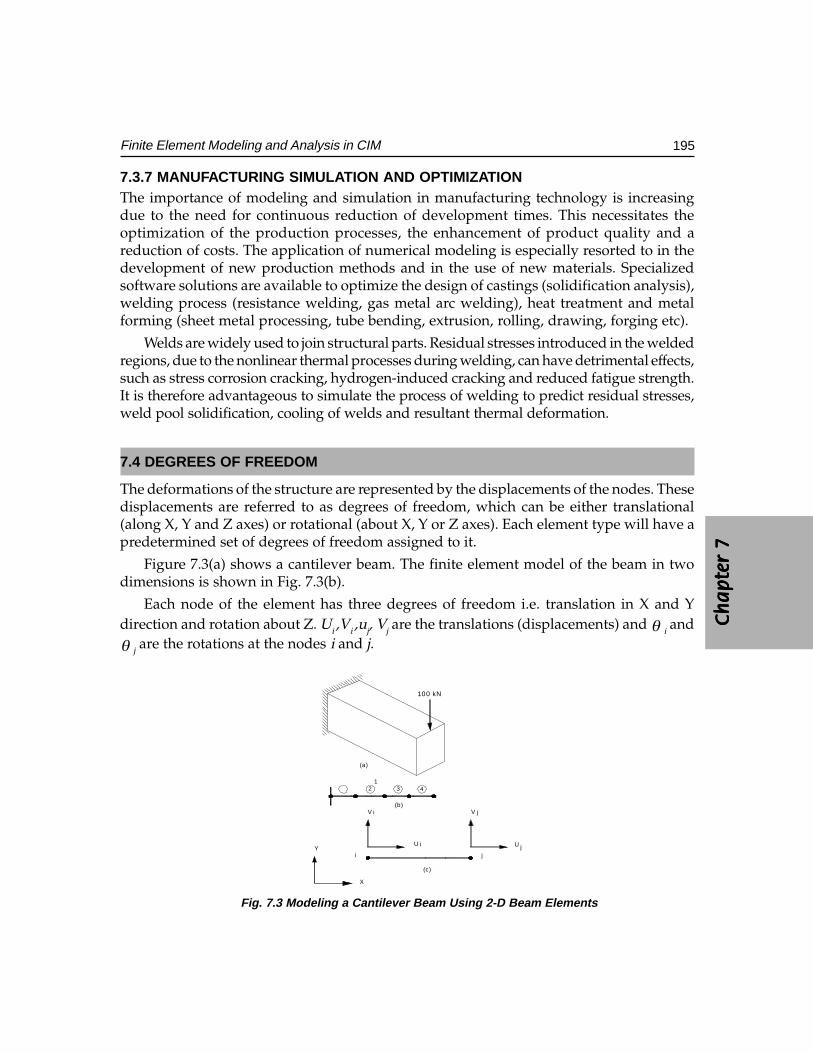
Ch
ap
ter
7C
ha
pte
r 7
Ch
ap
ter
7C
ha
pte
r 7
Ch
ap
ter
7
195Finite Element Modeling and Analysis in CIM
7.3.7 MANUFACTURING SIMULATION AND OPTIMIZATIONThe importance of modeling and simulation in manufacturing technology is increasingdue to the need for continuous reduction of development times. This necessitates theoptimization of the production processes, the enhancement of product quality and areduction of costs. The application of numerical modeling is especially resorted to in thedevelopment of new production methods and in the use of new materials. Specializedsoftware solutions are available to optimize the design of castings (solidification analysis),welding process (resistance welding, gas metal arc welding), heat treatment and metalforming (sheet metal processing, tube bending, extrusion, rolling, drawing, forging etc).
Welds are widely used to join structural parts. Residual stresses introduced in the weldedregions, due to the nonlinear thermal processes during welding, can have detrimental effects,such as stress corrosion cracking, hydrogen-induced cracking and reduced fatigue strength.It is therefore advantageous to simulate the process of welding to predict residual stresses,weld pool solidification, cooling of welds and resultant thermal deformation.
7.4 DEGREES OF FREEDOM
The deformations of the structure are represented by the displacements of the nodes. Thesedisplacements are referred to as degrees of freedom, which can be either translational(along X, Y and Z axes) or rotational (about X, Y or Z axes). Each element type will have apredetermined set of degrees of freedom assigned to it.
Figure 7.3(a) shows a cantilever beam. The finite element model of the beam in twodimensions is shown in Fig. 7.3(b).
Each node of the element has three degrees of freedom i.e. translation in X and Ydirection and rotation about Z. Ui ,Vi ,uj, Vj are the translations (displacements) and θ i andθ j are the rotations at the nodes i and j.
100 kN
12 3 4
V V
U U
i j
i
i
j
jY
X
(a)
(b)
(c)
Fig. 7.3 Modeling a Cantilever Beam Using 2-D Beam Elements
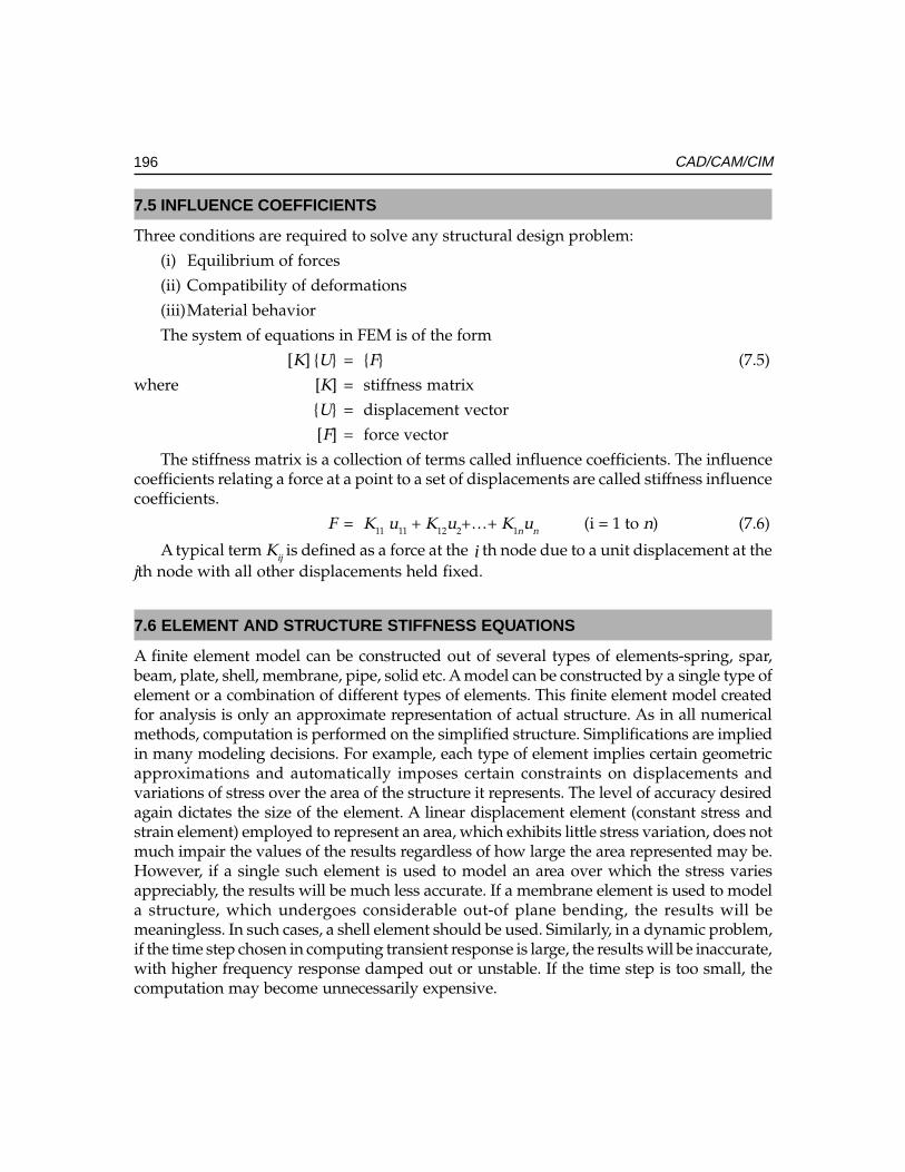
196 CAD/CAM/CIM
7.5 INFLUENCE COEFFICIENTS
Three conditions are required to solve any structural design problem:
(i) Equilibrium of forces
(ii) Compatibility of deformations
(iii)Material behavior
The system of equations in FEM is of the form
[K] {U} = {F} (7.5)
where [K] = stiffness matrix
{U} = displacement vector
[F] = force vector
The stiffness matrix is a collection of terms called influence coefficients. The influencecoefficients relating a force at a point to a set of displacements are called stiffness influencecoefficients.
F = K11 u11 + K12u2+…+ K1nun (i = 1 to n) (7.6)
A typical term Kij is defined as a force at the i th node due to a unit displacement at thejth node with all other displacements held fixed.
7.6 ELEMENT AND STRUCTURE STIFFNESS EQUATIONS
A finite element model can be constructed out of several types of elements-spring, spar,beam, plate, shell, membrane, pipe, solid etc. A model can be constructed by a single type ofelement or a combination of different types of elements. This finite element model createdfor analysis is only an approximate representation of actual structure. As in all numericalmethods, computation is performed on the simplified structure. Simplifications are impliedin many modeling decisions. For example, each type of element implies certain geometricapproximations and automatically imposes certain constraints on displacements andvariations of stress over the area of the structure it represents. The level of accuracy desiredagain dictates the size of the element. A linear displacement element (constant stress andstrain element) employed to represent an area, which exhibits little stress variation, does notmuch impair the values of the results regardless of how large the area represented may be.However, if a single such element is used to model an area over which the stress variesappreciably, the results will be much less accurate. If a membrane element is used to modela structure, which undergoes considerable out-of plane bending, the results will bemeaningless. In such cases, a shell element should be used. Similarly, in a dynamic problem,if the time step chosen in computing transient response is large, the results will be inaccurate,with higher frequency response damped out or unstable. If the time step is too small, thecomputation may become unnecessarily expensive.
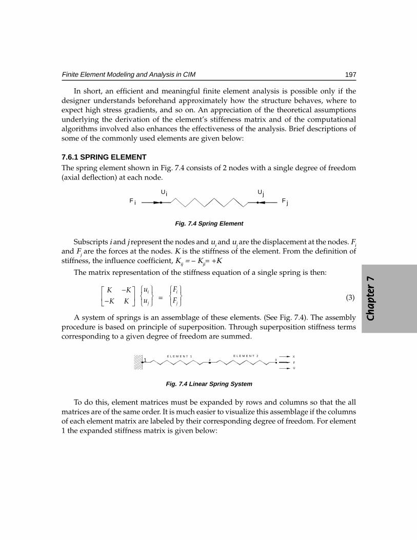
Ch
ap
ter
7C
ha
pte
r 7
Ch
ap
ter
7C
ha
pte
r 7
Ch
ap
ter
7
197Finite Element Modeling and Analysis in CIM
In short, an efficient and meaningful finite element analysis is possible only if thedesigner understands beforehand approximately how the structure behaves, where toexpect high stress gradients, and so on. An appreciation of the theoretical assumptionsunderlying the derivation of the element’s stiffeness matrix and of the computationalalgorithms involved also enhances the effectiveness of the analysis. Brief descriptions ofsome of the commonly used elements are given below:
7.6.1 SPRING ELEMENTThe spring element shown in Fig. 7.4 consists of 2 nodes with a single degree of freedom(axial deflection) at each node.
F i F j
Ui Uj
Fig. 7.4 Spring Element
Subscripts i and j represent the nodes and ui and uj are the displacement at the nodes. Fi
and Fj are the forces at the nodes. K is the stiffness of the element. From the definition ofstiffness, the influence coefficient, Kij = – Kji= +K
The matrix representation of the stiffness equation of a single spring is then:
K K
K K
− −
i
j
uu
=i
j
FF
(3)
A system of springs is an assemblage of these elements. (See Fig. 7.4). The assemblyprocedure is based on principle of superposition. Through superposition stiffness termscorresponding to a given degree of freedom are summed.
X
U
F321
E L E M E N T 2E L E M E N T 1
Fig. 7.4 Linear Spring System
To do this, element matrices must be expanded by rows and columns so that the allmatrices are of the same order. It is much easier to visualize this assemblage if the columnsof each element matrix are labeled by their corresponding degree of freedom. For element1 the expanded stiffness matrix is given below:
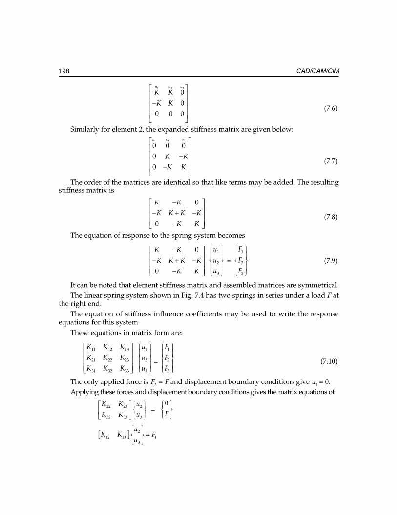
198 CAD/CAM/CIM
31 2
00
0 0 0
uu u
K K
K K
−
(7.6)
Similarly for element 2, the expanded stiffness matrix are given below:31 2
0 0 000
uu u
K KK K
− −
(7.7)
The order of the matrices are identical so that like terms may be added. The resultingstiffness matrix is
0
0
K K
K K K K
K K
− − + − −
(7.8)
The equation of response to the spring system becomes
0
0
K KK K K K
K K
− − + − −
1
2
3
u
u
u
= 1
2
3
F
F
F
(7.9)
It can be noted that element stiffness matrix and assembled matrices are symmetrical.The linear spring system shown in Fig. 7.4 has two springs in series under a load F at
the right end.The equation of stiffness influence coefficients may be used to write the response
equations for this system.These equations in matrix form are:
11 12 13
21 22 23
31 32 33
K K K
K K K
K K K
1
2
3
u
u
u
=
1
2
3
F
F
F
(7.10)
The only applied force is F3 = F and displacement boundary conditions give u1 = 0.Applying these forces and displacement boundary conditions gives the matrix equations of:
22 23 2
32 33 3
K K u
K K u
=0F
[ ] 212 13 1
3
uK K F
u
=
Ch
ap
ter
7C
ha
pte
r 7
Ch
ap
ter
7C
ha
pte
r 7
Ch
ap
ter
7
199Finite Element Modeling and Analysis in CIM
In the case of spring element, the element co-ordinate system is identical with the globalreference co-ordinate system. The assemblage of elements is valid only when alldisplacements and forces at a node have the same reference co-ordinate system.
Example:Example:Example:Example:Example: A short stepped bar 123 is shown in Fig. 7.5. The stiffness of the large sectionis 12 kN/mm and the stiffness of the small section is 8 kN/mm. End “1 “is fixed and anaxial load of 6 kN acts at node 3. Determine the displacements at node 2 and node 3.
2K1K6 k N
6 k N
8 k N / m m1 2 k N / m m
321
Fig. 7 .5 Stepped Bar and Spring Model
Solution.Solution.Solution.Solution.Solution. Using the matrix equation developed and taking u1 = 0.
12 12 012 20 80 8 8
− − − −
2
3
0X
X
=
1
06
F
(7.11)
Thus 20 X2–8X3 = 0 (7.12)
– 8 X2 + 8X3 = 6 (7.13)
Adding
12X2 = 6
X2 = 0.5 mm (Answer)(Answer)(Answer)(Answer)(Answer)
Substituting in (10)
10 – 8X3 = 0
X3 = 0.8 mm (Answer)(Answer)(Answer)(Answer)(Answer)
Strain in section 1-2 = X2/L1
Stress in section 1-2 = E (X2/L1)
Strain in section 2-3 = X2/L2
Stress in section 1-2 = E (X2/L2) where E is Young’s Modulus.
7.6.2 SPAR OR ROD ELEMENTA spar element is one, which can take only axial load, either tensile or compressive.Such elements are used in pin-jointed frames or trusses. Fig. 7.6 shows a spar element.The subscripts refer to element co-ordinate system. The element stiffness matrix forthe spar is:

200 CAD/CAM/CIM
[K] =
− − = − −
1 11 1
AE AEAEL L
AE AE LL L
(7.14)
where A is the area of cross section of the element and E is modulus of elasticity of thematerial.
In the case of spar element the orientation of the element has to be taken into accountin determining the stiffness matrix.
A R E A O F C R O S S S E C T I O N , AM O D U L U S O F E L A S T IC I T Y , E
ji
L
Fig. 7.6 Spar (rod) Element
j
F
FXi
FYj
X
Y
F
FYj
FX
Fig. 7.7 Spar Element Oriented at an Angle θθθθθ
Consider the pin-jointed member ij (shown in Fig. 7.7) subjected to a compressiveforce F that has components FXi, FYi, FXj, FYj at the ends. As a result of the structuredeforming and the member itself deforming the ends i, j are displaced by uxi, uyi, uxj, anduyj. The member is originally at an angle θ to the positive X-direction. The elongation ofthe member is given by:
eij =− −
− + −
( ) ( )j i j ij i j i
X X Y YUX UX UY UY
L L(7.15)
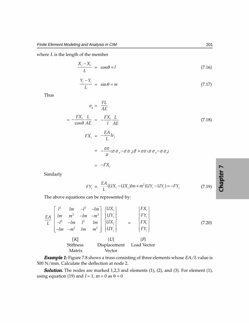
Ch
ap
ter
7C
ha
pte
r 7
Ch
ap
ter
7C
ha
pte
r 7
Ch
ap
ter
7
201Finite Element Modeling and Analysis in CIM
where L is the length of the member
j iX X
L
−= cos lθ = (7.16)
j iY Y
L
−= sin mθ = (7.17)
Thus
eij =FLAE
= cos
iFX LAEθ
− = iFX Ll AE
− (7.18)
iFX = j
EAle
L−
= �
� � � �� � � �
��� � � � � � � �
�
− − + −
= jFX−
Similarly
iFY = 2( ) ( )i j i j j
EAUX UX lm m UY UY FY
L− + − = − (7.19)
The above equations can be represented by:
EAL
− − − − − − − −
2 2
2 2
2 2
2 2
l lm l lm
lm m lm ml lm l lm
lm m lm m
i
i
j
j
UXUY
UXUY
=
i
i
i
j
FXFY
FXFY
(7.20)
[K] {U} {F}Stiffness Displacement Load Vector Matrix Vector
Example 1:Example 1:Example 1:Example 1:Example 1: Figure 7.8 shows a truss consisting of three elements whose EA/L value is500 N/mm. Calculate the deflection at node 2.
Solution.Solution.Solution.Solution.Solution. The nodes are marked 1,2,3 and elements (1), (2), and (3). For element (1),using equation (19) and l = 1, m = 0 as θ = 0
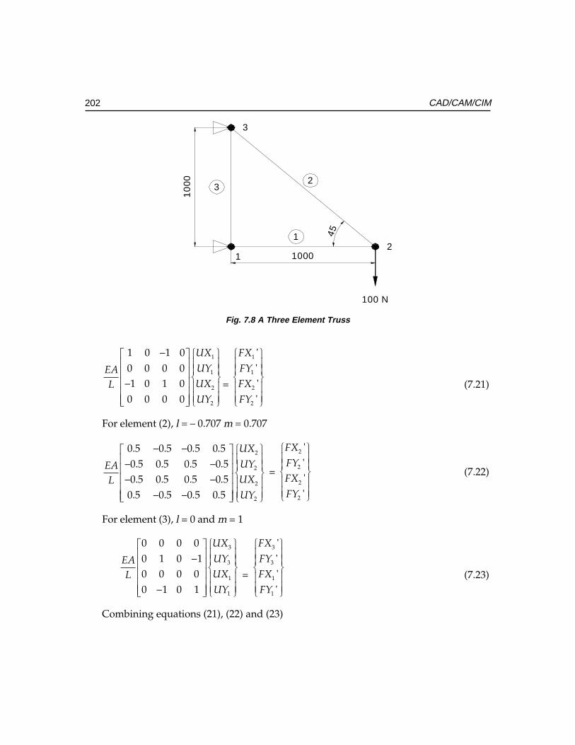
202 CAD/CAM/CIM
10
00
1000
1
23
100 N
21
3
45Fig. 7.8 A Three Element Truss
1
1
2
2
1 0 1 00 0 0 01 0 1 0
0 0 0 0
UX
UYEAUXLUY
− −
=
1
1
2
2
''''
FX
FYFX
FY
(7.21)
For element (2), l = – 0.707 m = 0.707
2
2
2
2
0.5 0.5 0.5 0.50.5 0.5 0.5 0.50.5 0.5 0.5 0.5
0.5 0.5 0.5 0.5
UX
UYEAUXLUY
− − − − − − − −
=
2
2
2
2
''''
FX
FYFX
FY
(7.22)
For element (3), l = 0 and m = 1
3
3
1
1
0 0 0 00 1 0 10 0 0 00 1 0 1
UX
UYEAUXLUY
− −
=
3
3
1
1
''''
FX
FYFX
FY
(7.23)
Combining equations (21), (22) and (23)
Ch
ap
ter
7C
ha
pte
r 7
Ch
ap
ter
7C
ha
pte
r 7
Ch
ap
ter
7
203Finite Element Modeling and Analysis in CIM
EAL
1 0 1 0 0 00 1 0 0 0 1
1 0 1.5 0.5 0.5 0.50 0 0.5 0.5 0.5 0.50 0 0.5 0.5 0.5 0.50 1 0.5 0.5 0.5 1.5
− − − − − − − − −
− − −
1
1
2
2
3
3
UX
UY
UXUY
UX
UY
=
1
1
2
2
3
3
FX
FY
FXFY
FX
FY
(7.24)
The boundary conditions for node displacement are:
1UX = 1 3 30, 0, 0, 0UY UX UY= = = (7.25)
2FY = 100− (7.26)
Equation (24) now becomes:
EAL
1 0 1 0 0 00 1 0 0 0 11 0 1.5 0.5 0.5 0.5
0 0 0.5 0.5 0.5 0.50 0 0.5 0.5 0.5 0.50 1 0.5 0.5 0.5 1.5
− − − − − − − − −
− − −
2
2
00
00
UX
UY
=
1
1
3
3
0100
FX
FY
FX
FY
−
(7.27)
Solving equation (25)
2 2(1.5 0.5 )EAUX UY
L− = 0 (7.28)
2 2( 0.5 0.5 )EA
UX UYL
− + = –100 (7.29)
From equations (26) and (27)
UX2 = – 0.2 mm (Answer)(Answer)(Answer)(Answer)(Answer)
Substituting in equation (27)
500(– 0.5 × – 0.2 + 0.5 UY2) = 100
0.1 + 0.5 UY2 = 0.2
0.5 UY2 = 0.1
UY2 = 0.2 mm (Answer)(Answer)(Answer)(Answer)(Answer)
7.6.3 BEAM ELEMENTAnalysis of pin-jointed frames is an ideal or limiting condition in structural analysis sinceno rotational restraints are supplied at the frictionless pin joints and consequently, no
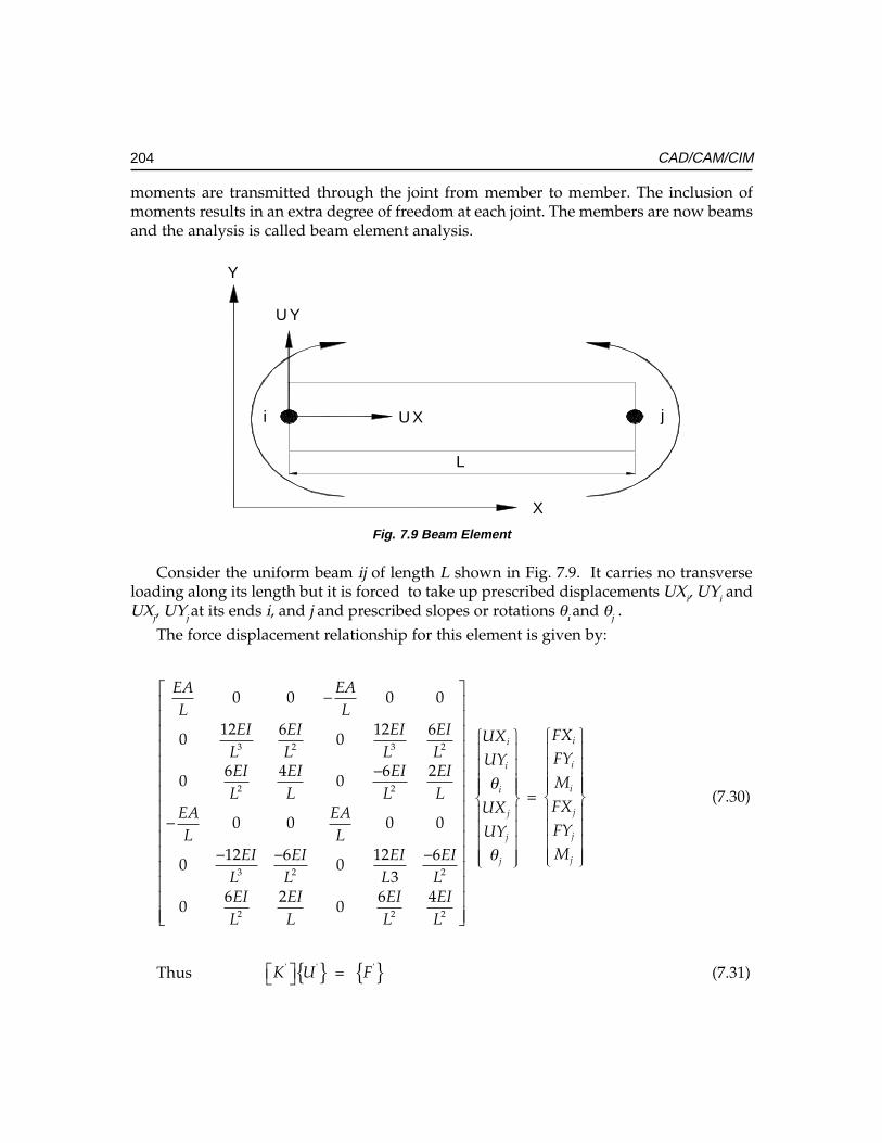
204 CAD/CAM/CIM
moments are transmitted through the joint from member to member. The inclusion ofmoments results in an extra degree of freedom at each joint. The members are now beamsand the analysis is called beam element analysis.
X
Y
i jU X
U Y
L
Fig. 7.9 Beam Element
Consider the uniform beam ij of length L shown in Fig. 7.9. It carries no transverseloading along its length but it is forced to take up prescribed displacements UXi, UYi andUXj, UYj at its ends i, and j and prescribed slopes or rotations θi and θj .
The force displacement relationship for this element is given by:
3 2 3 2
2 2
3 2 2
2 2 2
0 0 0 0
12 6 12 60 0
6 4 6 20 0
0 0 0 0
12 6 12 60 0
36 2 6 4
0 0
EA EAL L
EI EI EI EIL L L LEI EI EI EIL L L L
EA EAL L
EI EI EI EIL L L LEI EI EI EIL L L L
− − −
− − −
i
i
i
j
j
j
UXUY
UX
UY
θ
θ
=
i
i
i
j
j
j
FXFY
M
FX
FYM
(7.30)
Thus { }' 'K U = { }'F (7.31)
Ch
ap
ter
7C
ha
pte
r 7
Ch
ap
ter
7C
ha
pte
r 7
Ch
ap
ter
7
205Finite Element Modeling and Analysis in CIM
If the beam is assumed to be oriented at an angle θ to the global co-ordinate system,
{ }F = [ ]{ }'T F (7.32)
Where T is the transformation matrix
[ ]T =
0 0 0 00 0 0 0
0 0 0 0 00 0 0 00 0 0 00 0 0 0 0
l mm l
ll m
m ll
− −
(7.33)
From equation (29)
{ }'F = [ ]{ }'K U (7.34)
[ ]{ }T U = { }'U (7.35)
From equation (30)
[ ]{ }T F = { }'F (7.36)
[ ]{ }T F = [ ]{ }'K T U (7.37)
{ }F = [ ] [ ]{ } –1 'T K T U (7.38)
OR
{ }F = [ ]{ }K U (7.39)
7.6.4 PLANE STRESS/PLANE STRAIN FINITE ELEMENT ANALYSISDevelopment of element matrices for structures other than springs and spars by the aboveprocedure would be difficult. Two of the most common methods used in such cases are thedirect and variational methods. Both these methods depend upon choosing a displacementfunction to describe the relationship between displacement and the co-ordinates of thenodes of the elements. The displacement function enables the elements to simulate theactual displacement, strain and stress behavior within the chosen elasticity theory. Forexample, a linear displacement function models linear deflection patterns, but only constantstresses and strains within the element.
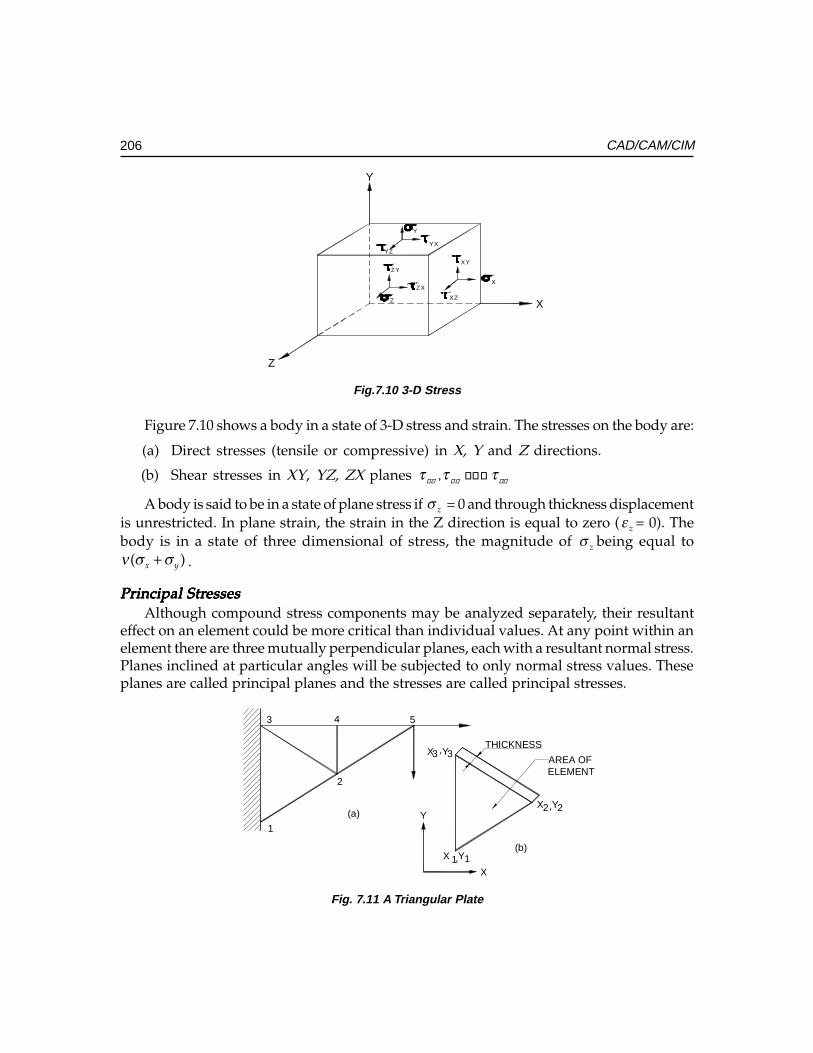
206 CAD/CAM/CIM
X
Z
Y
Y
YXYZ
Z
ZY
ZX
XZ
X
XY
Fig.7.10 3-D Stress
Figure 7.10 shows a body in a state of 3-D stress and strain. The stresses on the body are:
(a) Direct stresses (tensile or compressive) in X, Y and Z directions.
(b) Shear stresses in XY, YZ, ZX planes � ����� � �
τ τ τ
A body is said to be in a state of plane stress if zσ = 0 and through thickness displacementis unrestricted. In plane strain, the strain in the Z direction is equal to zero ( zε = 0). Thebody is in a state of three dimensional of stress, the magnitude of zσ being equal to
( )x yν σ σ+ .
Principal StrPrincipal StrPrincipal StrPrincipal StrPrincipal StressesessesessesessesessesAlthough compound stress components may be analyzed separately, their resultant
effect on an element could be more critical than individual values. At any point within anelement there are three mutually perpendicular planes, each with a resultant normal stress.Planes inclined at particular angles will be subjected to only normal stress values. Theseplanes are called principal planes and the stresses are called principal stresses.
(b)
(a)
THICKNESS
AREA OFELEMENT
,
,
, 33
22
11
X Y
X Y
X Y
Y
X
543
2
1
Fig. 7.11 A Triangular Plate
Ch
ap
ter
7C
ha
pte
r 7
Ch
ap
ter
7C
ha
pte
r 7
Ch
ap
ter
7
207Finite Element Modeling and Analysis in CIM
The finite element approach to continuum problems is developed as a direct extensionof the approach used in earlier sections. The method is outlined with respect to a thintriangular plate shown in Fig. 7.11. It is fixed along its edge 1-3 and loaded at 5. It isrequired to find the displacements under the loads and stresses in the plate. The plate isshown divided into 3 elements with 5 nodes.
The simplest assumption for the deformation within an element is a uniform state ofstrain throughout. This may be achieved by assuming displacements UX and UY to begiven by linear functions of x and y, the global co-ordinates.
Therefore,UX = 1 2 3x yα α α+ + (7.40)
UY = 1 2 3x yβ β β+ + (7.41)
The corresponding strains are
xε = 2
ux
α∂ =∂ (7.42)
yε = 2
uy
β∂ =∂ (7.43)
xyγ = 3 2
u vy x
α β∂ ∂+ = +∂ ∂
(7.44)
It can be seen that strains are constant. Using equations (38) and (39) the nodaldisplacements can be written as:
{ }U =
1
1
2
2
3
3
UX
UY
UXUY
UX
UY
=
1 1
1 1
2 2
2 2
3 3
3 3
1 0 0 00 0 0 11 0 0 00 0 0 11 0 0 00 0 0 1
X Y
X Y
X YX Y
X Y
X Y
1
2
3
1
2
3
αααβββ
(7.45)
= [ ]{ }A α (7.46)
Similarly
{ε} =
1
2
3
1
2
3
0 1 0 0 0 00 0 0 0 0 10 0 1 0 1 0
x
y
xy
αε
εε
εβ
γββ
=
(7.47)
208 CAD/CAM/CIM
= [ ]{ }Bα α (7.48)
{ε} = { }1 2 3
1 2 3
1 1 2 2 3 3
0 0 01
0 0 02
b b b
a a a UA
a b a b a a
(7.49)
= [B] {U} (7.50)
Where
a1 = X3 –X2 and b1 = Y2 –Y3
a2 = X1 –X3 b2 = Y3 –Y1
a3 = X2 –X1 b3 = Y1 –Y2
A = area of triangular element.
In plane stress, the through thickness stress σz = 0 and through thickness displacementsare unrestricted.
Thus,
xσ = 21 x y
E ε νεν
+ −(7.51)
yσ = 21 y x
E ε νεν
+ − (7.52)
xyτ = xyGγ (7.53)
or in matrix form
{σ} =x
y
xy
σστ
=
2 2
2 2
01 1
01 1
0 02(1 )
x
y
xy
E E
E E
E
νν ν ε
ν εν ν
γ
ν
− −
− − +
(7.54)
= [D] {ε} (7.56)
where E = 2G (1+v).
The coefficients of D matrix for place stress are:
Ch
ap
ter
7C
ha
pte
r 7
Ch
ap
ter
7C
ha
pte
r 7
Ch
ap
ter
7
209Finite Element Modeling and Analysis in CIM
11d = 22 1E
dν
=−
21d = 12 1E
dν
ν=
−
33d =2(1 )
Eν+
In place strain εz = 0 and σz = v (σx + σy).
For place strain
11d = 22 (1 )(1 2 )E
dν ν
=+ +
12d = 21 (1 )(1 2 )E
dν ν
=+ −
33d =2(1 )
Eν+
Substituting equation (7.50) in (7.55)
{σ} = [D]{ε} = [D] [B] {U} (7.56)
To obtain a set of nodal forces in equilibrium with the stresses in the element, theprinciple of virtual work is made use of.
The variational approach of virtual work is based upon the potential energy equationof the system. The potential energy is designated as
πp = U + W where U is the internal energy and
W is work done by external force.
U = { } { }12
T dσ ε ν∫
W = { } { }TP U dν∫Where {σ} = body forces, {U}= displacements.
The principle of virtual work states that the sum of the work done by the applied forceand the stored energy for the virtual displacement is zero.
U’ + WWWWW = 0
where U’ is the change in strain energy for the virtual displacement.
W’ is the work done by the virtual displacement.
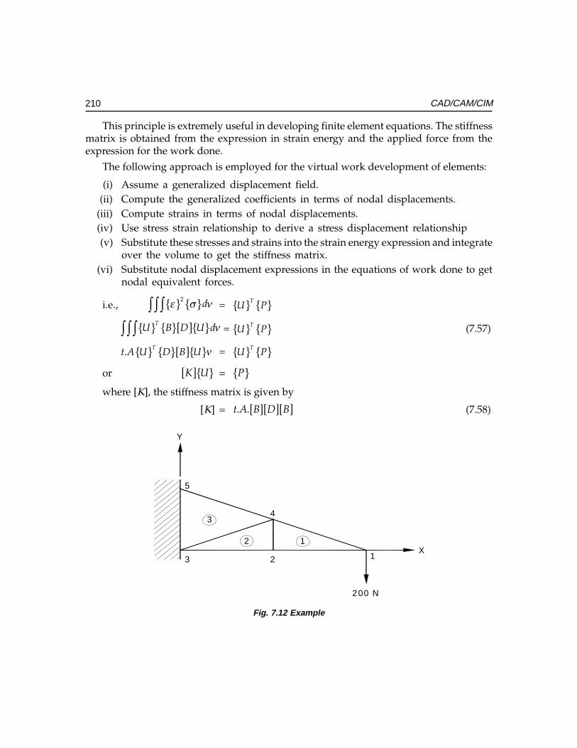
210 CAD/CAM/CIM
This principle is extremely useful in developing finite element equations. The stiffnessmatrix is obtained from the expression in strain energy and the applied force from theexpression for the work done.
The following approach is employed for the virtual work development of elements:
(i) Assume a generalized displacement field.(ii) Compute the generalized coefficients in terms of nodal displacements.
(iii) Compute strains in terms of nodal displacements.(iv) Use stress strain relationship to derive a stress displacement relationship(v) Substitute these stresses and strains into the strain energy expression and integrate
over the volume to get the stiffness matrix.(vi) Substitute nodal displacement expressions in the equations of work done to get
nodal equivalent forces.
i.e., { } { }2 dε σ ν∫ ∫ ∫ = { } { }TU P
{ } { }[ ]{ }TU B D U dν∫ ∫ ∫ = { } { }TU P (7.57)
{ } { }[ ]{ }. Tt A U D B U ν = { } { }TU P
or [ ]{ }K U = { }P
where [K], the stiffness matrix is given by
[K] = [ ][ ][ ]. .t A B D B (7.58)
Y
X12
3
123
4
5
200 N
Fig. 7.12 Example
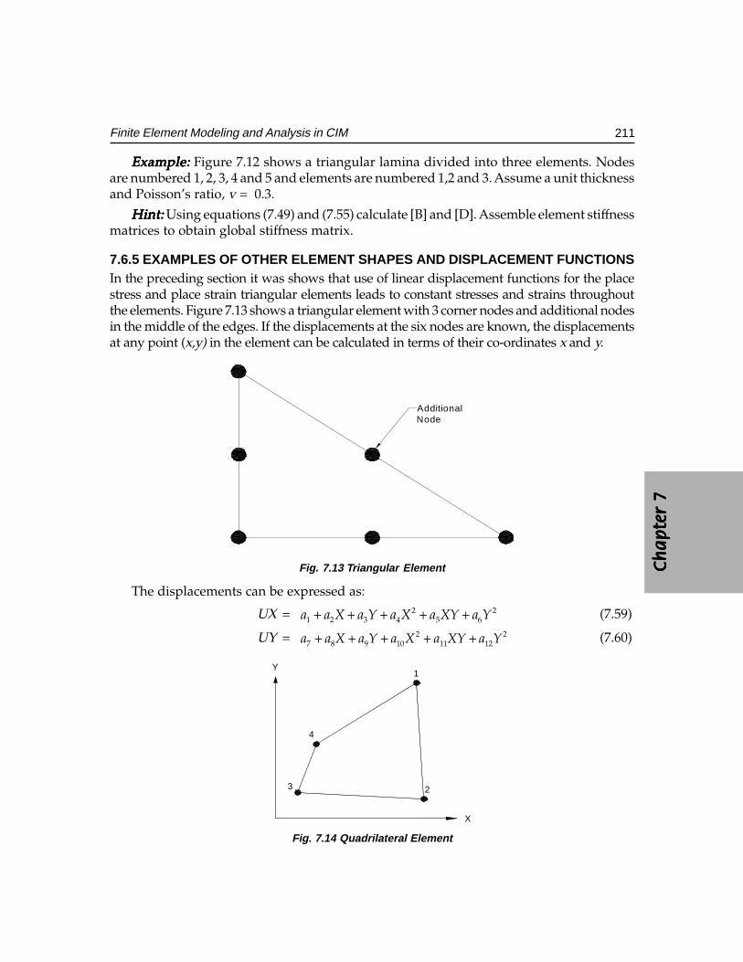
Ch
ap
ter
7C
ha
pte
r 7
Ch
ap
ter
7C
ha
pte
r 7
Ch
ap
ter
7
211Finite Element Modeling and Analysis in CIM
Example:Example:Example:Example:Example: Figure 7.12 shows a triangular lamina divided into three elements. Nodesare numbered 1, 2, 3, 4 and 5 and elements are numbered 1,2 and 3. Assume a unit thicknessand Poisson’s ratio, v = 0.3.
Hint:Hint:Hint:Hint:Hint: Using equations (7.49) and (7.55) calculate [B] and [D]. Assemble element stiffnessmatrices to obtain global stiffness matrix.
7.6.5 EXAMPLES OF OTHER ELEMENT SHAPES AND DISPLACEMENT FUNCTIONSIn the preceding section it was shows that use of linear displacement functions for the placestress and place strain triangular elements leads to constant stresses and strains throughoutthe elements. Figure 7.13 shows a triangular element with 3 corner nodes and additional nodesin the middle of the edges. If the displacements at the six nodes are known, the displacementsat any point (x,y) in the element can be calculated in terms of their co-ordinates x and y.
AdditionalNode
Fig. 7.13 Triangular Element
The displacements can be expressed as:
UX = 2 21 2 3 4 5 6a a X a Y a X a XY a Y+ + + + + (7.59)
UY = 2 27 8 9 10 11 12a a X a Y a X a XY a Y+ + + + + (7.60)
X
Y1
23
4
Fig. 7.14 Quadrilateral Element
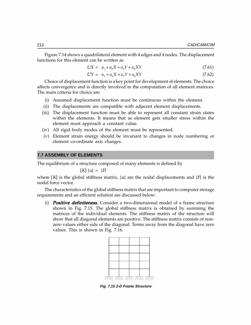
212 CAD/CAM/CIM
Figure 7.14 shows a quadrilateral element with 4 edges and 4 nodes. The displacementfunctions for this element can be written as
UX = 1 2 3 4a a X a Y a XY+ + + (7.61)
UY = 5 6 7 8a a X a Y a XY+ + + (7.62)
Choice of displacement function is a key point for development of elements. The choiceaffects convergence and is directly involved in the computation of all element matrices.The main criteria for choice are:
(i) Assumed displacement function must be continuous within the element.(ii) The displacements are compatible with adjacent element displacements.
(iii) The displacement function must be able to represent all constant strain stateswithin the elements. It means that as element gets smaller stress within theelement must approach a constant value.
(iv) All rigid body modes of the element must be represented.(v) Element strain energy should be invariant to changes in node numbering or
element co-ordinate axis changes.
7.7 ASSEMBLY OF ELEMENTS
The equilibrium of a structure composed of many elements is defined by
[K] {u} = {F}
where [K] is the global stiffness matrix, {u} are the nodal displacements and {F} is thenodal force vector.
The characteristics of the global stiffness matrix that are important to computer storagerequirements and an efficient solution are discussed below:
(i) Positive definiteness. Positive definiteness. Positive definiteness. Positive definiteness. Positive definiteness. Consider a two-dimensional model of a frame structureshown in Fig. 7.15. The global stiffness matrix is obtained by summing thematrices of the individual elements. The stiffness matrix of the structure willshow that all diagonal elements are positive. The stiffness matrix consists of non-zero values either side of the diagonal. Terms away from the diagonal have zerovalues. This is shown in Fig. 7.16.
Fig. 7.15 2-D Frame Structure
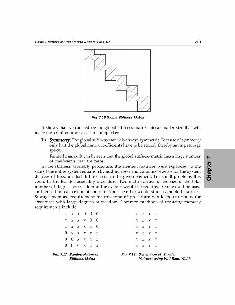
Ch
ap
ter
7C
ha
pte
r 7
Ch
ap
ter
7C
ha
pte
r 7
Ch
ap
ter
7
213Finite Element Modeling and Analysis in CIM
Fig. 7.16 Global Stiffness Matrix
It shows that we can reduce the global stiffness matrix into a smaller size that willmake the solution process easier and quicker.
(ii) Symmetry: Symmetry: Symmetry: Symmetry: Symmetry: The global stiffness matrix is always symmetric. Because of symmetryonly half the global matrix coefficients have to be stored, thereby saving storagespace.Banded matrix: It can be seen that the global stiffness matrix has a large numberof coefficients that are zeros.
In the stiffness assembly procedure, the element matrices were expanded to thesize of the entire system equation by adding rows and columns of zeros for the systemdegrees of freedom that did not exist in the given element. For small problems thiscould be the feasible assembly procedure. Two matrix arrays of the size of the totalnumber of degrees of freedom of the system would be required. One would be usedand reused for each element computation. The other would store assembled matrices.Storage memory requirement for this type of procedure would be enormous forstructures with large degrees of freedom. Common methods of reducing memoryrequirements include:
0 0 00 0
000 00 0 0
x x x
x x x x
x x x x x
x x x x x
x x x x
x x x
x x x x
x x x x
x x x x
x x x x
x x x x
x x x x
Fig. 7.17 Banded Nature of Fig. 7.18 Generation of SmallerStiffness Matrix Matrices using Half Band Width
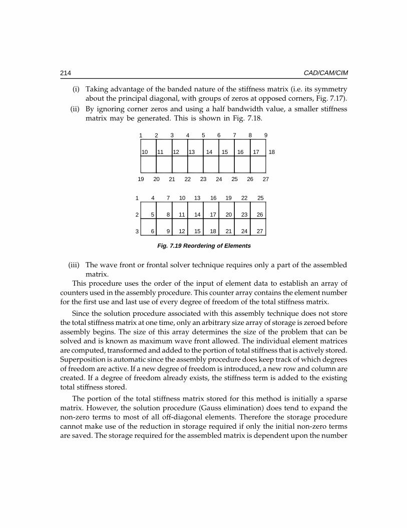
214 CAD/CAM/CIM
(i) Taking advantage of the banded nature of the stiffness matrix (i.e. its symmetryabout the principal diagonal, with groups of zeros at opposed corners, Fig. 7.17).
(ii) By ignoring corner zeros and using a half bandwidth value, a smaller stiffnessmatrix may be generated. This is shown in Fig. 7.18.
1 2 3 4 5 6 7 8 9
10 11 12 13 14 15 16 17 18
19 20 21 22 23 24 25 26 27
1
2
3
4
5
6
7
8
9
10
11
12
13
14
15
16
17
18
19
20
21
22
23
24
25
26
27
Fig. 7.19 Reordering of Elements
(iii) The wave front or frontal solver technique requires only a part of the assembledmatrix.
This procedure uses the order of the input of element data to establish an array ofcounters used in the assembly procedure. This counter array contains the element numberfor the first use and last use of every degree of freedom of the total stiffness matrix.
Since the solution procedure associated with this assembly technique does not storethe total stiffness matrix at one time, only an arbitrary size array of storage is zeroed beforeassembly begins. The size of this array determines the size of the problem that can besolved and is known as maximum wave front allowed. The individual element matricesare computed, transformed and added to the portion of total stiffness that is actively stored.Superposition is automatic since the assembly procedure does keep track of which degreesof freedom are active. If a new degree of freedom is introduced, a new row and column arecreated. If a degree of freedom already exists, the stiffness term is added to the existingtotal stiffness stored.
The portion of the total stiffness matrix stored for this method is initially a sparsematrix. However, the solution procedure (Gauss elimination) does tend to expand thenon-zero terms to most of all off-diagonal elements. Therefore the storage procedurecannot make use of the reduction in storage required if only the initial non-zero termsare saved. The storage required for the assembled matrix is dependent upon the number
Ch
ap
ter
7C
ha
pte
r 7
Ch
ap
ter
7C
ha
pte
r 7
Ch
ap
ter
7
215Finite Element Modeling and Analysis in CIM
of active degrees of freedom within the assembled matrix. This number is called thewave front size. The active degrees of freedom are those that still have other elementsthat will contribute to them. If an active degree of freedom is closed, assembly is finishedso no more elements contribute to it and this degree of freedom is eliminated by Gausselimination process.
To reduce maximum wave front size, the elements must be ordered from the solutionphase so that element for which each node is mentioned first is as close as possible insequence to the element for which it is mentioned last. In geometric terms, the elementshould be ordered so that the wave front sweeps through the model continuously fromone end to the other in the direction in which it has the largest number of nodes. Forexample, consider a model having 3 nodes in one direction and nine nodes in the otherdirection as shown in Fig. 7.19. The element should be ordered along one three-node edgeand ordering progresses towards the other three-node edge. In this way equations will bedeleted from the assembled matrix as soon as possible after they are added, thus minimizingwave front size.
(iv) Solving the equations for each element in turn whilst storing the others on discand then writing out the reduced equations to the disc. Back substitution is thenused with the reduced equations, which are read back into the core memory.
7.8 FINITE ELEMENT ANALYSIS PACKAGES
With the widespread adoption of CAE approach to design, finite element analysis becameintegrated with the design and analysis process. There are several CAD packages availabletoday with built-in FEA capabilities (I-DEAS, PRO/E, Unigraphics, CATIA etc). Thereare also several FEA packages with interface to database of solid modeling packages tocarryout FE Analysis. FEA packages by themselves possess modeling capabilities (wireframe or solid modeling) so that they can be used independent of CAD software. Thereare several such software packages available today which can run on mainframes,minicomputers as well as PC’s. NASTRAN, NISA, PATRAN, ANSYS, COSMOS, ALGOR,PCTRAN etc., are some of the well-known analysis packages.
7.8.1 MODELING CAPABILITIES OF TYPICAL FINITE ELEMENT SOFTWARE PACKAGEThe following list gives some of the capabilities of finite element software packages.
(i) Static analysis. Calculation of stresses and displacements in a structure subjectedto static loads.
(ii) Dynamic analysis. Calculation of transient and steady state response of a structureto loads which vary with respect to time.
216 CAD/CAM/CIM
(iii) Modal analysis. Computation of natural frequencies associated mode shapes of thestructure, response spectrum analysis, random vibration and forced vibrationproblems.
(iv) Stability analysis. Determination of buckling loads on a structure.
(v) Heat transfer. Computation of temperature distribution and heat flow within astructure under steady state and transient conditions.
(vi) Field problems. Analysis of field intensity and flux density of a magnetic field,analysis of field problems in acoustics and fluid mechanics.
(vii) Coupling effects. Solution techniques for interfacing multiple field effects suchas displacement, forces, temperature, heat flows, electrical voltage and current,magnetic field intensity and flux, and fluid pressure and velocity.
(viii) Non-linear capabilities. Computations taking into account the temperaturedependency of material properties, plasticity, non-linear elasticity, creep, swelling,large deflections, and work hardening.
(ix) Material properties. Analysis of isotropic, orthotropic, sandwich plates, andcomposites.
Analysis capabilities are today extended to overlay composite solid, laminatedcomposite shell, sandwich shell, fatigue, and fracture. Typical loading situations areconcentrated loads, body forces, surface forces, non-zero nodal displacements, nodaltemperature gradients etc.
7.9 GENERAL STRUCTURE OF A FINITE ELEMENT ANALYSIS PROCEDURE
The analysis of a structure during its design process is accomplished by the solution of thepartial differential equations which describe the given model. This involves the followingthree steps (Fig. 7.20).
(i) The description of the geometry the physical characteristics and the mesh (pre-processing)
(ii) The application of the finite element analysis (solution)
(iii) The visualization and interpretation of the results of the solution (post processing).
These three steps are quite distinct and correspond to creating, on the programminglevel, the three distinct modules:
(i) Module to enter the data
(ii) Module to perform the analysis
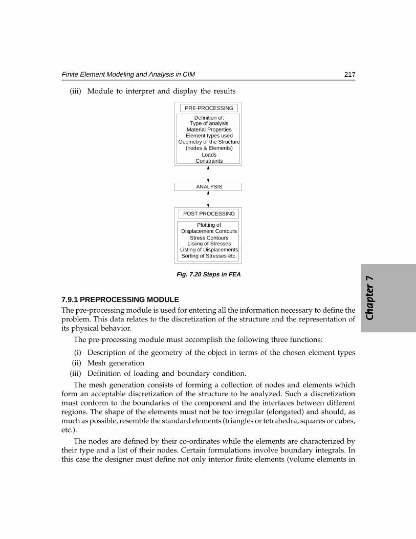
Ch
ap
ter
7C
ha
pte
r 7
Ch
ap
ter
7C
ha
pte
r 7
Ch
ap
ter
7
217Finite Element Modeling and Analysis in CIM
(iii) Module to interpret and display the results
PRE-PROCESSING
Sorting of Stresses etc.Listing of Displacements
Lisiing of StressesStress Contours
Displacement ContoursPlotting of
POST PROCESSING
ANALYSIS
ConstraintsLoads
(nodes & Elements)Geometry of the Structure
Element types usedMaterial Properties
Type of analysisDefinition of:
Fig. 7.20 Steps in FEA
7.9.1 PREPROCESSING MODULEThe pre-processing module is used for entering all the information necessary to define theproblem. This data relates to the discretization of the structure and the representation ofits physical behavior.
The pre-processing module must accomplish the following three functions:
(i) Description of the geometry of the object in terms of the chosen element types(ii) Mesh generation
(iii) Definition of loading and boundary condition.
The mesh generation consists of forming a collection of nodes and elements whichform an acceptable discretization of the structure to be analyzed. Such a discretizationmust conform to the boundaries of the component and the interfaces between differentregions. The shape of the elements must not be too irregular (elongated) and should, asmuch as possible, resemble the standard elements (triangles or tetrahedra, squares or cubes,etc.).
The nodes are defined by their co-ordinates while the elements are characterized bytheir type and a list of their nodes. Certain formulations involve boundary integrals. Inthis case the designer must define not only interior finite elements (volume elements in
218 CAD/CAM/CIM
three dimensions and surface elements in two dimensions) but also boundary finite elements(surface elements in three dimensions and line elements in two dimensions) on thecorresponding boundaries.
It is also necessary to describe the physical characteristics of the elements, such asdescription of material properties (e.g., thermal conductivity, modulus of elasticity, density,Poisson’s ratio); description of heat sources, description of boundary conditions, anddescription of initial conditions (for time dependent problems).
Generally, this information is entered region by region of the component. Thedescription of the geometry is sometimes implicitly linked to the meshing. However, thetrend at present is to separate the two. The description of the geometry is done first andthen the mesh is generated. The most extreme case of this separation is the use of twoseparate specialized programs: a solid modeler for the geometrical input and a meshgenerator for the discretization.
More than one type of element can be used in a model, including two dimensionalelements where all forces and displacements act in a plane; axisymmetric elements forsolids of revolution that are also two-dimensional but have node displacements inradial and axial directions; three-dimensional solid elements where forces anddisplacements act in all three directions or when a structure has a complex geometrythat does not allow two-dimensional analysis. Specialty elements such as plate andbeam types are used where sections of a structure behave according to conventionalplate and beam theory.
Elements with nodes at vertices generally model only a linear variation of displacementwith constant strain. Elements are also available, however, with nodes at edges. Theseelements can model high-order variations in displacements and strain within an element.Many elements with nodes along their sides are “Isoparametric” where additional nodesallow element sides to form curved boundaries. These elements also increase accuracy.Isoparametric models can cut model construction times but require more processing timeper element.
7.9.2 PRE-PROCESSING FROM CAD MODELIn computer aided engineering the product development starts with a CAD model. Thismodel is then subjected to several types of analysis (FEA, mechanisms analysis etc.) toverify the model and explore modifications to design. This requires the transfer of CADdatabase to the finite analysis software. This can be carried out broadly in two ways.
(a)(a)(a)(a)(a) Using a prUsing a prUsing a prUsing a prUsing a preprepreprepreprocessor packageocessor packageocessor packageocessor packageocessor packageCommercial packages like HyperMesh are available which will carry out pre-processing of CAD model, so that time consuming tasks of node generation, elementgeneration etc. can be avoided. For example, if the CAD model is made by a PRO/E or CATIA software package, the FEA model can be created by a finite elementmodeling interface software. The automatic mesh generation facility (volume
Ch
ap
ter
7C
ha
pte
r 7
Ch
ap
ter
7C
ha
pte
r 7
Ch
ap
ter
7
219Finite Element Modeling and Analysis in CIM
meshing or area meshing as the case may be) takes out the tedium of meshing. Themodel is more accurate as the redefinition of the geometry is avoided.
The advantages of this approach are:
• Reduced time and engineering analysis cost.• Reduced overhead costs of maintaining multiple pre- and post-processing tools.• Minimized “new user” learning curves.• Increased efficiency.• Open-architecture design and customization functionality.• Reduced redundancy and model development costs.• Simplified modeling process for complex geometry through high-speed, high-
quality auto meshing, hexa-meshing and tetra-meshing.• Dramatic increase in end-user modeling efficiency.
There are several ways in which finite element models are created from CAD models.Different meshing approaches are used for creating the models. These are described below:
(i) Shell meshing: Shell meshing: Shell meshing: Shell meshing: Shell meshing: Shell meshing is performed using triangular mesh elements. Thisis designed to mesh surfaces. Surfaces are designated for shell meshing in three ways:(a) Pair meshing. In this case, part surfaces are paired so that material is
sandwiched between selected surfaces. These surfaces are then compressedtogether to a single surface using thickness as a property. The shell meshingis done in the compressed plane.
(b) Boundary meshing. The surface of a part is shell meshed using this option.(c) Quilt meshing. Two dimensional features are shell meshed using this option.
(ii) Solid meshing: Solid meshing: Solid meshing: Solid meshing: Solid meshing: Solid meshing of interiors of solid is done with tetrahedralelements.
(iii) Mixed meshing:Mixed meshing:Mixed meshing:Mixed meshing:Mixed meshing: Shell and tetrahedral meshing technique can be usedadvantageously for many parts. If the model contains thin and thick parts, thinparts can be shell meshed and thick parts can be meshed with tetrahedral elements.The corresponding tetrahedral mesh elements are forced to coincide to provideanalytical continuity.
7.9.3 PROCEDURE FOR CREATION OF FINITE ELEMENT MODEL FROM SOLIDMODEL
The following procedure is recommended to create a finite element model from a solidmodel:
(i) Simplify the model by removing features which are unnecessary to the finiteelement analysis. Features like rounds, chamfers and small holes can be suppressed.Dimensions can be modified to align edges and surfaces are very close. Anotherway to simplify the model is to use symmetry of the part to be modeled. Onlya portion of a symmetrical object needs modeling.
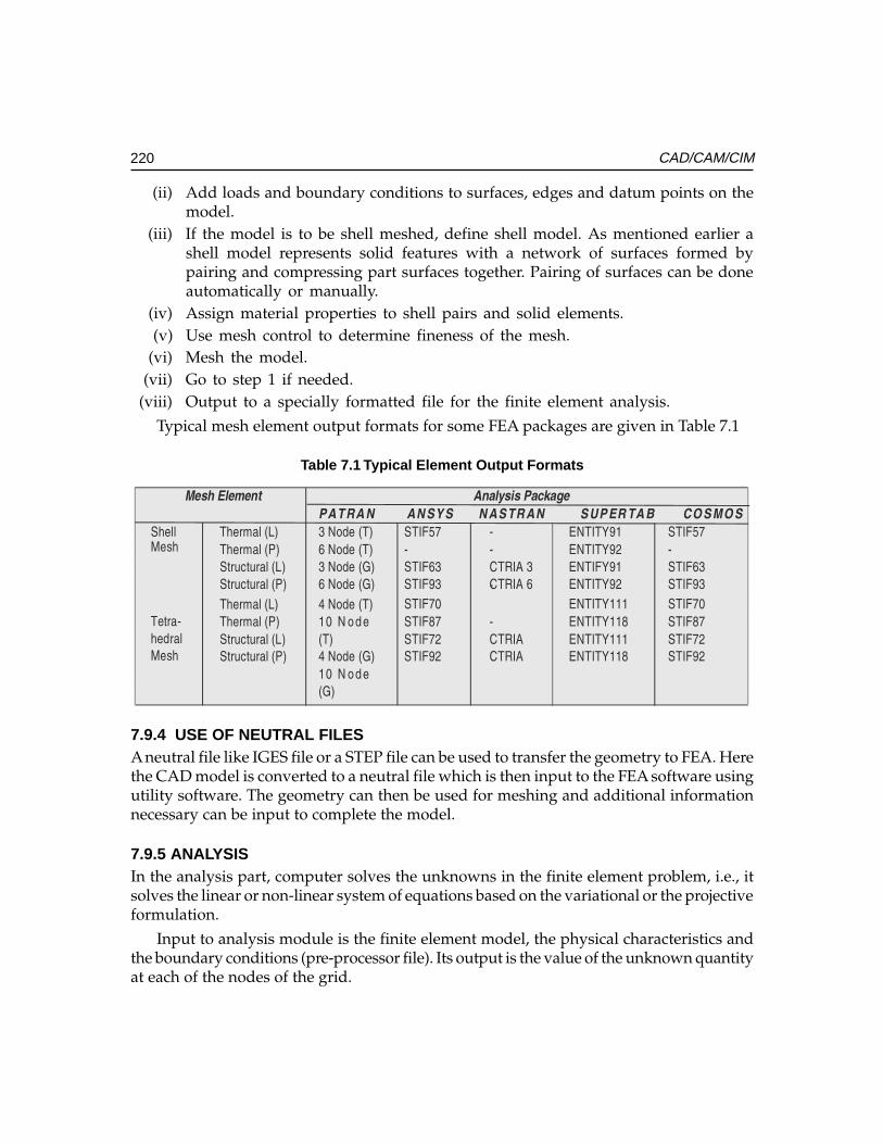
220 CAD/CAM/CIM
(ii) Add loads and boundary conditions to surfaces, edges and datum points on themodel.
(iii) If the model is to be shell meshed, define shell model. As mentioned earlier ashell model represents solid features with a network of surfaces formed bypairing and compressing part surfaces together. Pairing of surfaces can be doneautomatically or manually.
(iv) Assign material properties to shell pairs and solid elements.(v) Use mesh control to determine fineness of the mesh.
(vi) Mesh the model.(vii) Go to step 1 if needed.
(viii) Output to a specially formatted file for the finite element analysis.
Typical mesh element output formats for some FEA packages are given in Table 7.1
Table 7.1 Typical Element Output Formats
������������� �� ����� � ���
���� � �� �� � � �� �� �� � � �� �� � �� � �� �
����������
�����������
������������
�������������
����������
����������
����������
����������
������
��
������
������
��
��
��������
��������
����!�"�
����!�#�
����!�"�
����!�#�
������
��
������
������
�����$�%���
�
�
������
�������
$�%��
����������
�����������
������������
�������������
&���������
"' � ���
���
&���������
"' � ���
����
����'�
���(��
����#�
����#�
��
��
������
������
����!"""�
����!""(�
����!"""�
����!""(�
�
����'�
���(��
����#�
����#�
7.9.4 USE OF NEUTRAL FILESA neutral file like IGES file or a STEP file can be used to transfer the geometry to FEA. Herethe CAD model is converted to a neutral file which is then input to the FEA software usingutility software. The geometry can then be used for meshing and additional informationnecessary can be input to complete the model.
7.9.5 ANALYSISIn the analysis part, computer solves the unknowns in the finite element problem, i.e., itsolves the linear or non-linear system of equations based on the variational or the projectiveformulation.
Input to analysis module is the finite element model, the physical characteristics andthe boundary conditions (pre-processor file). Its output is the value of the unknown quantityat each of the nodes of the grid.
Ch
ap
ter
7C
ha
pte
r 7
Ch
ap
ter
7C
ha
pte
r 7
Ch
ap
ter
7
221Finite Element Modeling and Analysis in CIM
Two large classes of methods are used to solve these sets of equations: point or blockmethods of relaxation or global matrix methods. The latter, more popular today, requiresseveral steps:
(i) Creation of sub-matrices and sub-vectors corresponding to each individual finiteelement;
(ii) Assembly of these elementary matrices and vectors to build the system matrixand right hand vector;
(iii) Solution of the linear system of equations.
The solution of linear algebraic systems can be done in several ways: by direct methods(Gauss, Choleski), semi-direct methods, or block iterative methods (Gauss-Seidel). Whenthe system of equations is non-linear, these operations are repeated in an iterative scheme(Gauss-Seidel, Newton-Kantorovich, Newton-Raphson). When the problem is timedependent, these steps must be repeated for each time step (implicit or explicit finitedifference methods, Crank-Nicholson, Predictor-Corrector, Guyan reduction techniques,and Householder method).
7.9.6 POSTPROCESSORThe large amount of data is generated in the solution phase (several thousand of nodalvalues in complex problems). These are often too much to be understood without furtherprocessing. The post processor presents the output of the problem in a manner which iseasily understood and interpreted by the user.
The postprThe postprThe postprThe postprThe postprocessor performs two tasks:ocessor performs two tasks:ocessor performs two tasks:ocessor performs two tasks:ocessor performs two tasks:
(i) Extraction of significant information:Extraction of significant information:Extraction of significant information:Extraction of significant information:Extraction of significant information: The information may be related to localquantities (magnetic flux density, stress distribution) or global quantities (heatflux, electromagnetic forces, etc.).
(ii) Synthetic prSynthetic prSynthetic prSynthetic prSynthetic presentation of the numerical data via graphics facilities:esentation of the numerical data via graphics facilities:esentation of the numerical data via graphics facilities:esentation of the numerical data via graphics facilities:esentation of the numerical data via graphics facilities: This makesthe data more understandable and easier to interpret (stress plots, displacement plots,isothermal plots, temperature Vs time curves, magnetic field along a line, etc.).
7.10 ARCHITECTURE OF FINITE ELEMENT SOFTWARE
Finite element software packages are structured in many ways. At one extreme, a pre-andpostprocessor may not exist at all. In this case, the input data file can be created with a texteditor. The results of the analysis can then be processed directly by the user. In more popularFEA softwares, however, the pre and postprocessors are highly developed to reduce thetime involved in the input of data and the analysis of the results of the simulation. Theyboth require high performance interactive graphics modules.
The solution phase, however, needs classical computational resources: arithmeticoperations, large primary memory, mass storage, etc. The diversity of facilities (good
222 CAD/CAM/CIM
interactivity and high quality graphics for pre-and post-processing) and computational powerand storage facilities for the solver are the main reasons for the organization of the softwarein these separate modules, sometimes implemented on different computers (minicomputerfor interactive graphics and a mainframe or parallel computer for computation).
The data is transferred from one program to another (perhaps from one computer toanother) through various files.
The structure most frequently encountered can be classified into the following threegroups:
(i) One prOne prOne prOne prOne program for all functions: ogram for all functions: ogram for all functions: ogram for all functions: ogram for all functions: When all the functions are contained in a singleprogram, rapid interaction among all operations is facilitated. It is well suited toapplications with numerous input/output operations.
(ii) One prOne prOne prOne prOne program for program for program for program for program for pre-and post-pre-and post-pre-and post-pre-and post-pre-and post-processing:ocessing:ocessing:ocessing:ocessing: In this case, the user has at his/herdisposal all of the interactive facilities and all of the computational facilities. He/she can describe the problem and analyze the results with a high performanceinteractive graphics terminal (perhaps a mainframe, super or parallel computer).
(iii) One prOne prOne prOne prOne program for each function:ogram for each function:ogram for each function:ogram for each function:ogram for each function: This method involves the construction of a setof procedures from different sources. A procedure may be run by means of a setof dedicated programs. For instance, if we have two different mesh generators,one completely automatic, and the other semi-automatic, we can first do anautomatic meshing of the problem. Then, if the result does not look good (toomany elements, symmetry not taken into account) we can modify the resultsusing the semi-automatic mesh generator. In both cases the problem will use thesame solution technique.
7.11 USING A FINITE ELEMENT ANALYSIS PACKAGE FOR SIMPLE PROBLEMS
Simple problems can be solved using the modeling facilities available within a FEA package.
To illustrate the use of a PC-based finite element package, the procedure of analysisusing ANSYS is discussed in the following sections.
7.11.1 MODES OF OPERATIONThe mode of operation of a finite element package will vary depending on the type andversion of the package. In some cases the pre-processing, analysis and post-processing arecarried out by separate modules. Often these segments of the analysis are executedconsecutively. The procedure in the case of ANSYS 10 is given below:
All ANSYS data input is written to a ASCII coded file (FILE18.DAT). This file may besaved and is suitable for printout, and rewound when analysis is performed. Hence it isnecessary to copy this file before analysis if the data is to be preserved. The analysis can becarried out in an interactive or batch mode. In batch mode, the user creates two files-apreprocessing file and a post processing file. These files can be created using an editor.
Ch
ap
ter
7C
ha
pte
r 7
Ch
ap
ter
7C
ha
pte
r 7
Ch
ap
ter
7
223Finite Element Modeling and Analysis in CIM
7.11.2 PREPROCESSINGThe first step in finite element analysis is creation of a model that breaks a structure intosimple standardized shapes or by a common coordinate grid system. The coordinate points,called nodes, are locations in the model where output information is provided.
Finite element packages provide exhaustive element libraries to enable adequatemodeling of even complicated parts. A list of elements used in the ANSYS package isgiven in the next section.
7.12 ELEMENTS IN A FINITE ELEMENT ANALYSIS SOFTWARE
Several elements are available in a typical finite element analysis software. Some of themare:
LINK1 - 2-D Spar (or Truss)
PLANE2 - 2-D 6-Node Triangular Structural Solid
BEAM3 - 2-D Elastic Beam
BEAM4 - 3-D Elastic Beam
SOLID5 - 3-D Coupled-Field Solid
COMBIN7 - Revolute Joint
LINK8 - 3-D Spar (or Truss)
INFIN9 - 2-D Infinite Boundary
LINK10 - Tension-only or Compression-only Spar
LINK11 - Linear Actuator
CONTAC12 - 2-D Point-to-Point Contact
PLANE13 - 2-D Coupled-Field Solid
COMBIN14 - Spring-Damper
PIPE16 - Elastic Straight Pipe
PIPE17 - Elastic Pipe Tee
PIPE18 - Elastic Curved Pipe (Elbow)
PIPE20 - Plastic Straight Pipe
MASS21 - Structural Mass
BEAM23 - 2-D Plastic Beam
BEAM24 - 3-D Thin-walled Beam
PLANE25 - Axisymmetric-Harmonic 4-Node Structural Solid
CONTAC26 - 2-D Point-to-Ground Contact
MATRIX27 - Stiffness, Damping, or Mass Matrix
224 CAD/CAM/CIM
SHELL28 - Shear/Twist Panel
FLUID29 - 2-D Acoustic Fluid
FLUID30 - 3-D Acoustic Fluid
LINK31 - Radiation Link
LINK32 - 2-D Conduction Bar
LINK33 - 3-D Conduction Bar
LINK34 - Convection Link
PLANE35 - 2-D 6-Node Triangular Thermal Solid
SOURC36 - Current Source
COMBIN37 - Control
FLUID38 - Dynamic Fluid Coupling
COMBIN39 - Nonlinear Spring
COMBIN40 - Combination
SHELL41 - Membrane Shell
PLANE42 - 2-D Structural Solid
SHELL43 - 4-Node Plastic Large Strain Shell
BEAM44 - 3-D Elastic Tapered Unsymmetric Beam
SOLID45 - 3-D Structural Solid
SOLID46 - 3-D 8-Node Layered Structural Solid
INFIN47 - 3-D Infinite Boundary
CONTAC48 - 2-D Point-to-Surface Contact
CONTAC49 - 3-D Point-to-Surface Contact
MATRIX50 - Superelement (or Substructure)
SHELL51 - Axisymmetric Structural Shell
CONTAC52 - 3-D Point-to-Point Contact
PLANE53 - 2-D 8-Node Magnetic Solid
BEAM54 - 2-D Elastic Tapered Unsymmetric Beam
PLANE55 - 2-D Thermal Solid
HYPER56 - 2-D 4-Node Mixed U-P Hyperelastic Solid
SHELL57 - Thermal Shell
HYPER58 - 3-D 8-Node Mixed U-P Hyperelastic SolidPIPE59 - Immersed Pipe or CablePIPE60 - Plastic Curved Pipe (Elbow)
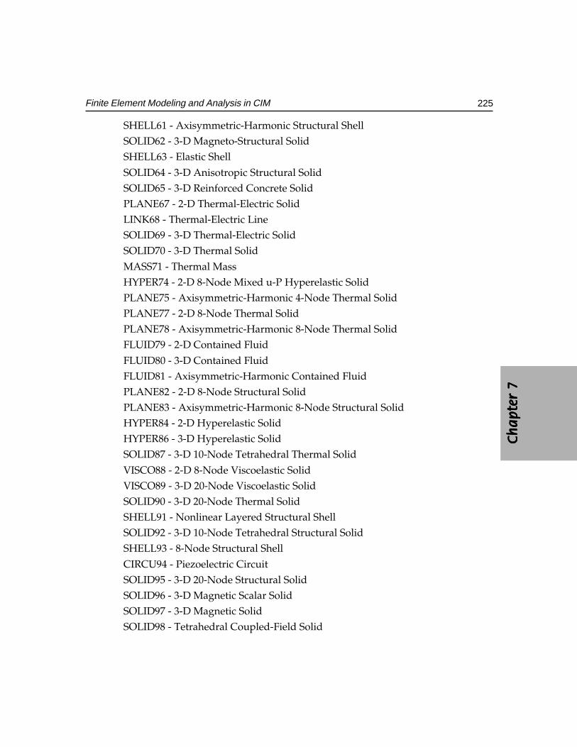
Ch
ap
ter
7C
ha
pte
r 7
Ch
ap
ter
7C
ha
pte
r 7
Ch
ap
ter
7
225Finite Element Modeling and Analysis in CIM
SHELL61 - Axisymmetric-Harmonic Structural ShellSOLID62 - 3-D Magneto-Structural SolidSHELL63 - Elastic Shell
SOLID64 - 3-D Anisotropic Structural SolidSOLID65 - 3-D Reinforced Concrete SolidPLANE67 - 2-D Thermal-Electric SolidLINK68 - Thermal-Electric LineSOLID69 - 3-D Thermal-Electric SolidSOLID70 - 3-D Thermal Solid
MASS71 - Thermal MassHYPER74 - 2-D 8-Node Mixed u-P Hyperelastic SolidPLANE75 - Axisymmetric-Harmonic 4-Node Thermal SolidPLANE77 - 2-D 8-Node Thermal SolidPLANE78 - Axisymmetric-Harmonic 8-Node Thermal SolidFLUID79 - 2-D Contained Fluid
FLUID80 - 3-D Contained FluidFLUID81 - Axisymmetric-Harmonic Contained FluidPLANE82 - 2-D 8-Node Structural SolidPLANE83 - Axisymmetric-Harmonic 8-Node Structural SolidHYPER84 - 2-D Hyperelastic SolidHYPER86 - 3-D Hyperelastic SolidSOLID87 - 3-D 10-Node Tetrahedral Thermal Solid
VISCO88 - 2-D 8-Node Viscoelastic SolidVISCO89 - 3-D 20-Node Viscoelastic SolidSOLID90 - 3-D 20-Node Thermal SolidSHELL91 - Nonlinear Layered Structural ShellSOLID92 - 3-D 10-Node Tetrahedral Structural SolidSHELL93 - 8-Node Structural Shell
CIRCU94 - Piezoelectric CircuitSOLID95 - 3-D 20-Node Structural SolidSOLID96 - 3-D Magnetic Scalar SolidSOLID97 - 3-D Magnetic SolidSOLID98 - Tetrahedral Coupled-Field Solid
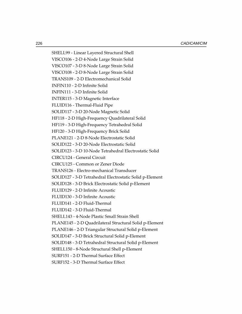
226 CAD/CAM/CIM
SHELL99 - Linear Layered Structural ShellVISCO106 - 2-D 4-Node Large Strain SolidVISCO107 - 3-D 8-Node Large Strain SolidVISCO108 - 2-D 8-Node Large Strain SolidTRANS109 - 2-D Electromechanical SolidINFIN110 - 2-D Infinite SolidINFIN111 - 3-D Infinite SolidINTER115 - 3-D Magnetic InterfaceFLUID116 - Thermal-Fluid PipeSOLID117 - 3-D 20-Node Magnetic SolidHF118 - 2-D High-Frequency Quadrilateral SolidHF119 - 3-D High-Frequency Tetrahedral SolidHF120 - 3-D High-Frequency Brick SolidPLANE121 - 2-D 8-Node Electrostatic SolidSOLID122 - 3-D 20-Node Electrostatic SolidSOLID123 - 3-D 10-Node Tetrahedral Electrostatic SolidCIRCU124 - General CircuitCIRCU125 - Common or Zener DiodeTRANS126 - Electro-mechanical TransducerSOLID127 - 3-D Tetrahedral Electrostatic Solid p-ElementSOLID128 - 3-D Brick Electrostatic Solid p-ElementFLUID129 - 2-D Infinite AcousticFLUID130 - 3-D Infinite AcousticFLUID141 - 2-D Fluid-ThermalFLUID142 - 3-D Fluid-ThermalSHELL143 - 4-Node Plastic Small Strain ShellPLANE145 - 2-D Quadrilateral Structural Solid p-ElementPLANE146 - 2-D Triangular Structural Solid p-ElementSOLID147 - 3-D Brick Structural Solid p-ElementSOLID148 - 3-D Tetrahedral Structural Solid p-ElementSHELL150 - 8-Node Structural Shell p-ElementSURF151 - 2-D Thermal Surface EffectSURF152 - 3-D Thermal Surface Effect
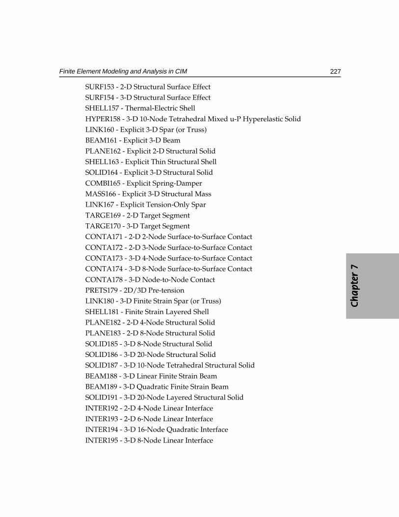
Ch
ap
ter
7C
ha
pte
r 7
Ch
ap
ter
7C
ha
pte
r 7
Ch
ap
ter
7
227Finite Element Modeling and Analysis in CIM
SURF153 - 2-D Structural Surface EffectSURF154 - 3-D Structural Surface EffectSHELL157 - Thermal-Electric ShellHYPER158 - 3-D 10-Node Tetrahedral Mixed u-P Hyperelastic SolidLINK160 - Explicit 3-D Spar (or Truss)BEAM161 - Explicit 3-D BeamPLANE162 - Explicit 2-D Structural SolidSHELL163 - Explicit Thin Structural ShellSOLID164 - Explicit 3-D Structural SolidCOMBI165 - Explicit Spring-DamperMASS166 - Explicit 3-D Structural MassLINK167 - Explicit Tension-Only SparTARGE169 - 2-D Target SegmentTARGE170 - 3-D Target SegmentCONTA171 - 2-D 2-Node Surface-to-Surface ContactCONTA172 - 2-D 3-Node Surface-to-Surface ContactCONTA173 - 3-D 4-Node Surface-to-Surface ContactCONTA174 - 3-D 8-Node Surface-to-Surface ContactCONTA178 - 3-D Node-to-Node ContactPRETS179 - 2D/3D Pre-tensionLINK180 - 3-D Finite Strain Spar (or Truss)SHELL181 - Finite Strain Layered ShellPLANE182 - 2-D 4-Node Structural SolidPLANE183 - 2-D 8-Node Structural SolidSOLID185 - 3-D 8-Node Structural SolidSOLID186 - 3-D 20-Node Structural SolidSOLID187 - 3-D 10-Node Tetrahedral Structural SolidBEAM188 - 3-D Linear Finite Strain BeamBEAM189 - 3-D Quadratic Finite Strain BeamSOLID191 - 3-D 20-Node Layered Structural SolidINTER192 - 2-D 4-Node Linear InterfaceINTER193 - 2-D 6-Node Linear InterfaceINTER194 - 3-D 16-Node Quadratic InterfaceINTER195 - 3-D 8-Node Linear Interface
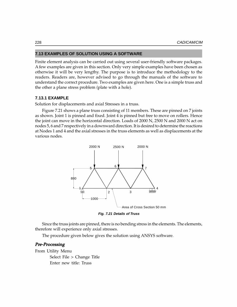
228 CAD/CAM/CIM
7.13 EXAMPLES OF SOLUTION USING A SOFTWARE
Finite element analysis can be carried out using several user-friendly software packages.A few examples are given in this section. Only very simple examples have been chosen asotherwise it will be very lengthy. The purpose is to introduce the methodology to thereaders. Readers are, however advised to go through the manuals of the software tounderstand the correct procedure. Two examples are given here. One is a simple truss andthe other a plane stress problem (plate with a hole).
7.13.1 EXAMPLESolution for displacements and axial Stresses in a truss.
Figure 7.21 shows a plane truss consisting of 11 members. These are pinned on 7 jointsas shown. Joint 1 is pinned and fixed. Joint 4 is pinned but free to move on rollers. Hencethe joint can move in the horizontal direction. Loads of 2000 N, 2500 N and 2000 N act onnodes 5, 6 and 7 respectively in a downward direction. It is desired to determine the reactionsat Nodes 1 and 4 and the axial stresses in the truss elements as well as displacements at thevarious nodes.
2000 N 2500 N 2000 N
12 3
4
56
7
880
1000
Area of Cross Section 50 mm
Fig. 7.21 Details of Truss
Since the truss joints are pinned, there is no bending stress in the elements. The elements,therefore will experience only axial stresses.
The procedure given below gives the solution using ANSYS software.
PrPrPrPrPre-Pre-Pre-Pre-Pre-Processingocessingocessingocessingocessing
From Utility MenuSelect File > Change TitleEnter new title: Truss
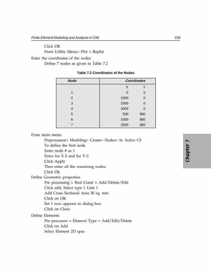
Ch
ap
ter
7C
ha
pte
r 7
Ch
ap
ter
7C
ha
pte
r 7
Ch
ap
ter
7
229Finite Element Modeling and Analysis in CIM
Click OKFrom Utility Menu> Plot > Replot
Enter the coordinates of the nodesDefine 7 nodes as given in Table 7.2
Table 7.2 Coordinates of the Nodes
Node Coordinates
X Y
1 0 0
2 1000 0
3 2000 0
4 3000 0
5 500 880
6 1500 880
7 2500 880
From main menuPreprocessor> Modeling> Create> Nodes> In Active CSTo define the first nodeEnter node # as 1Enter for X 0 and for Y 0Click ApplyThen enter all the remaining nodes.Click Ok
Define Geometric properties.Pre processing > Real Const > Add/Delete/EditClick add. Select type 1 Link 1Add Cross Sectional Area 50 sq. mmClick on OKSet 1 now appears in dialog box.Click on Close.
Define ElementsPre processor > Element Type > Add/Edit/DeleteClick on AddSelect Element 2D spar.
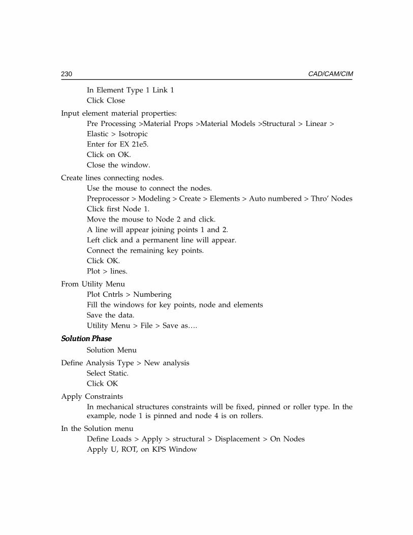
230 CAD/CAM/CIM
In Element Type 1 Link 1Click Close
Input element material properties:Pre Processing >Material Props >Material Models >Structural > Linear >Elastic > IsotropicEnter for EX 21e5.Click on OK.Close the window.
Create lines connecting nodes.Use the mouse to connect the nodes.Preprocessor > Modeling > Create > Elements > Auto numbered > Thro’ NodesClick first Node 1.Move the mouse to Node 2 and click.A line will appear joining points 1 and 2.Left click and a permanent line will appear.Connect the remaining key points.Click OK.Plot > lines.
From Utility MenuPlot Cntrls > NumberingFill the windows for key points, node and elementsSave the data.Utility Menu > File > Save as….
Solution PhaseSolution PhaseSolution PhaseSolution PhaseSolution Phase
Solution Menu
Define Analysis Type > New analysisSelect Static.Click OK
Apply ConstraintsIn mechanical structures constraints will be fixed, pinned or roller type. In theexample, node 1 is pinned and node 4 is on rollers.
In the Solution menuDefine Loads > Apply > structural > Displacement > On NodesApply U, ROT, on KPS Window
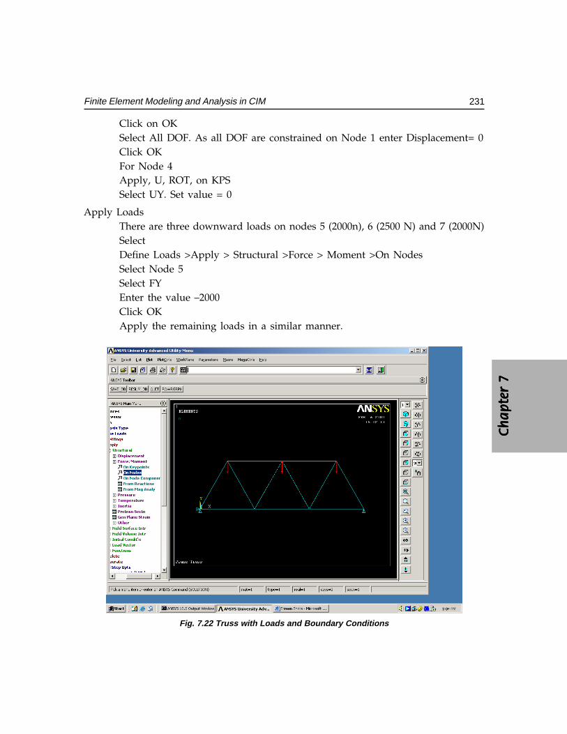
Ch
ap
ter
7C
ha
pte
r 7
Ch
ap
ter
7C
ha
pte
r 7
Ch
ap
ter
7
231Finite Element Modeling and Analysis in CIM
Click on OKSelect All DOF. As all DOF are constrained on Node 1 enter Displacement= 0Click OKFor Node 4Apply, U, ROT, on KPSSelect UY. Set value = 0
Apply LoadsThere are three downward loads on nodes 5 (2000n), 6 (2500 N) and 7 (2000N)SelectDefine Loads >Apply > Structural >Force > Moment >On NodesSelect Node 5Select FYEnter the value –2000Click OKApply the remaining loads in a similar manner.
Fig. 7.22 Truss with Loads and Boundary Conditions
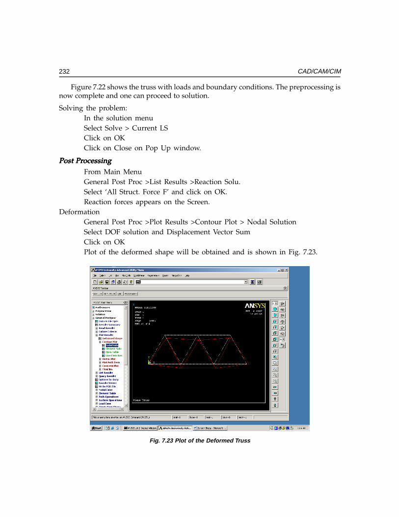
232 CAD/CAM/CIM
Figure 7.22 shows the truss with loads and boundary conditions. The preprocessing isnow complete and one can proceed to solution.
Solving the problem:In the solution menuSelect Solve > Current LSClick on OKClick on Close on Pop Up window.
Post PrPost PrPost PrPost PrPost Processingocessingocessingocessingocessing
From Main MenuGeneral Post Proc >List Results >Reaction Solu.Select ‘All Struct. Force F’ and click on OK.Reaction forces appears on the Screen.
DeformationGeneral Post Proc >Plot Results >Contour Plot > Nodal SolutionSelect DOF solution and Displacement Vector SumClick on OKPlot of the deformed shape will be obtained and is shown in Fig. 7.23.
Fig. 7.23 Plot of the Deformed Truss
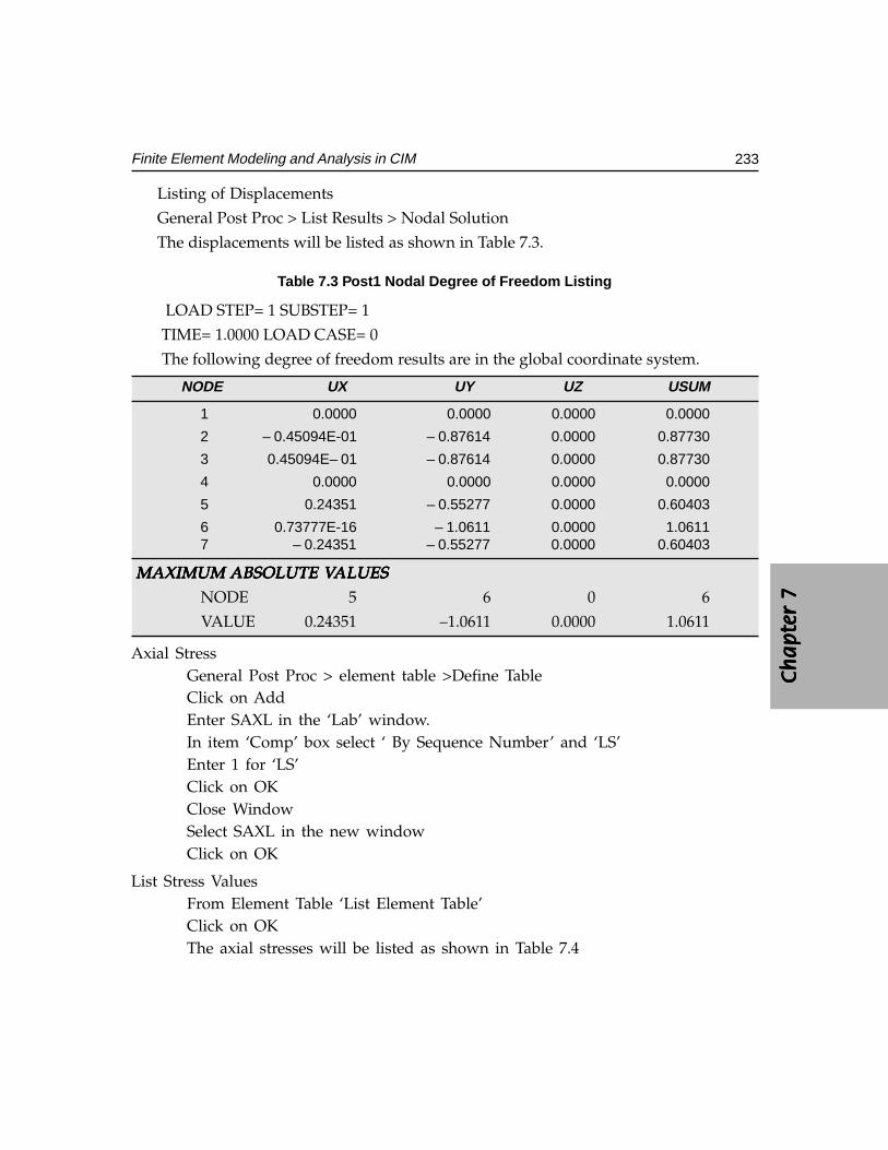
Ch
ap
ter
7C
ha
pte
r 7
Ch
ap
ter
7C
ha
pte
r 7
Ch
ap
ter
7
233Finite Element Modeling and Analysis in CIM
Listing of Displacements
General Post Proc > List Results > Nodal Solution
The displacements will be listed as shown in Table 7.3.
Table 7.3 Post1 Nodal Degree of Freedom Listing
LOAD STEP= 1 SUBSTEP= 1
TIME= 1.0000 LOAD CASE= 0
The following degree of freedom results are in the global coordinate system.
NODE UX UY UZ USUM
1 0.0000 0.0000 0.0000 0.0000
2 – 0.45094E-01 – 0.87614 0.0000 0.87730
3 0.45094E– 01 – 0.87614 0.0000 0.87730
4 0.0000 0.0000 0.0000 0.0000
5 0.24351 – 0.55277 0.0000 0.60403
6 0.73777E-16 – 1.0611 0.0000 1.0611 7 – 0.24351 – 0.55277 0.0000 0.60403
MAXIMUM MAXIMUM MAXIMUM MAXIMUM MAXIMUM ABSOLUTE VABSOLUTE VABSOLUTE VABSOLUTE VABSOLUTE VALUESALUESALUESALUESALUES NODE 5 6 0 6
VALUE 0.24351 –1.0611 0.0000 1.0611
Axial StressGeneral Post Proc > element table >Define TableClick on AddEnter SAXL in the ‘Lab’ window.In item ‘Comp’ box select ‘ By Sequence Number’ and ‘LS’Enter 1 for ‘LS’Click on OKClose WindowSelect SAXL in the new windowClick on OK
List Stress ValuesFrom Element Table ‘List Element Table’Click on OKThe axial stresses will be listed as shown in Table 7.4
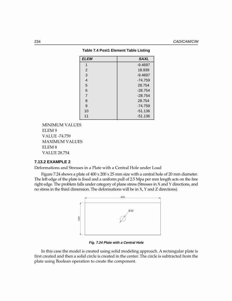
234 CAD/CAM/CIM
Table 7.4 Post1 Element Table Listing
ELEM SAXL
1 -9.46972 18.9393 -9.46974 -74.7595 28.7546 -28.7547 -28.7548 28.7549 -74.759
10 -51.13611 -51.136
MINIMUM VALUES ELEM 9 VALUE -74.759 MAXIMUM VALUES ELEM 8 VALUE 28.754
7.13.2 EXAMPLE 2Deformations and Stresses in a Plate with a Central Hole under Load
Figure 7.24 shows a plate of 400 x 200 x 25 mm size with a central hole of 20 mm diameter.The left edge of the plate is fixed and a uniform pull of 2.5 Mpa per mm length acts on the freeright edge. The problem falls under category of plane stress (Stresses in X and Y directions, andno stress in the third dimension. The deformations will be in X, Y and Z directions).
Ø 30
400
20
0
Fig. 7.24 Plate with a Central Hole
In this case the model is created using solid modeling approach. A rectangular plate isfirst created and then a solid circle is created in the center. The circle is subtracted from theplate using Boolean operation to create the component.
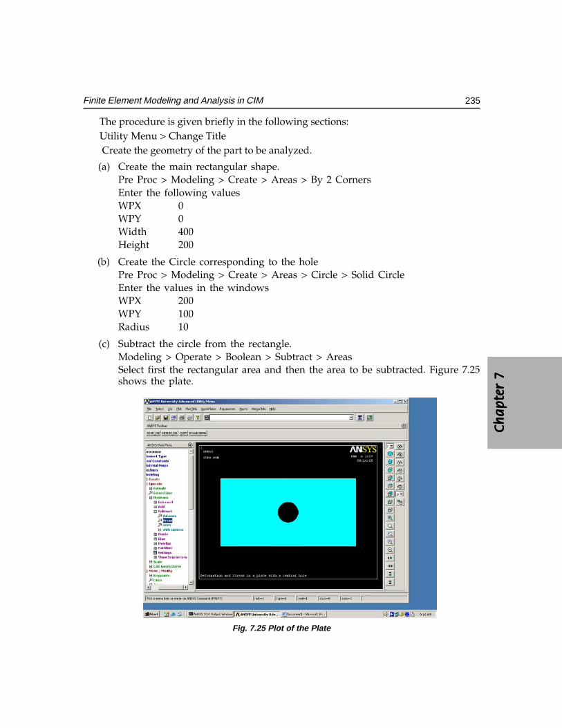
Ch
ap
ter
7C
ha
pte
r 7
Ch
ap
ter
7C
ha
pte
r 7
Ch
ap
ter
7
235Finite Element Modeling and Analysis in CIM
The procedure is given briefly in the following sections:Utility Menu > Change Title Create the geometry of the part to be analyzed.
(a) Create the main rectangular shape.Pre Proc > Modeling > Create > Areas > By 2 CornersEnter the following valuesWPX 0WPY 0Width 400Height 200
(b) Create the Circle corresponding to the holePre Proc > Modeling > Create > Areas > Circle > Solid CircleEnter the values in the windowsWPX 200WPY 100Radius 10
(c) Subtract the circle from the rectangle.Modeling > Operate > Boolean > Subtract > AreasSelect first the rectangular area and then the area to be subtracted. Figure 7.25shows the plate.
Fig. 7.25 Plot of the Plate
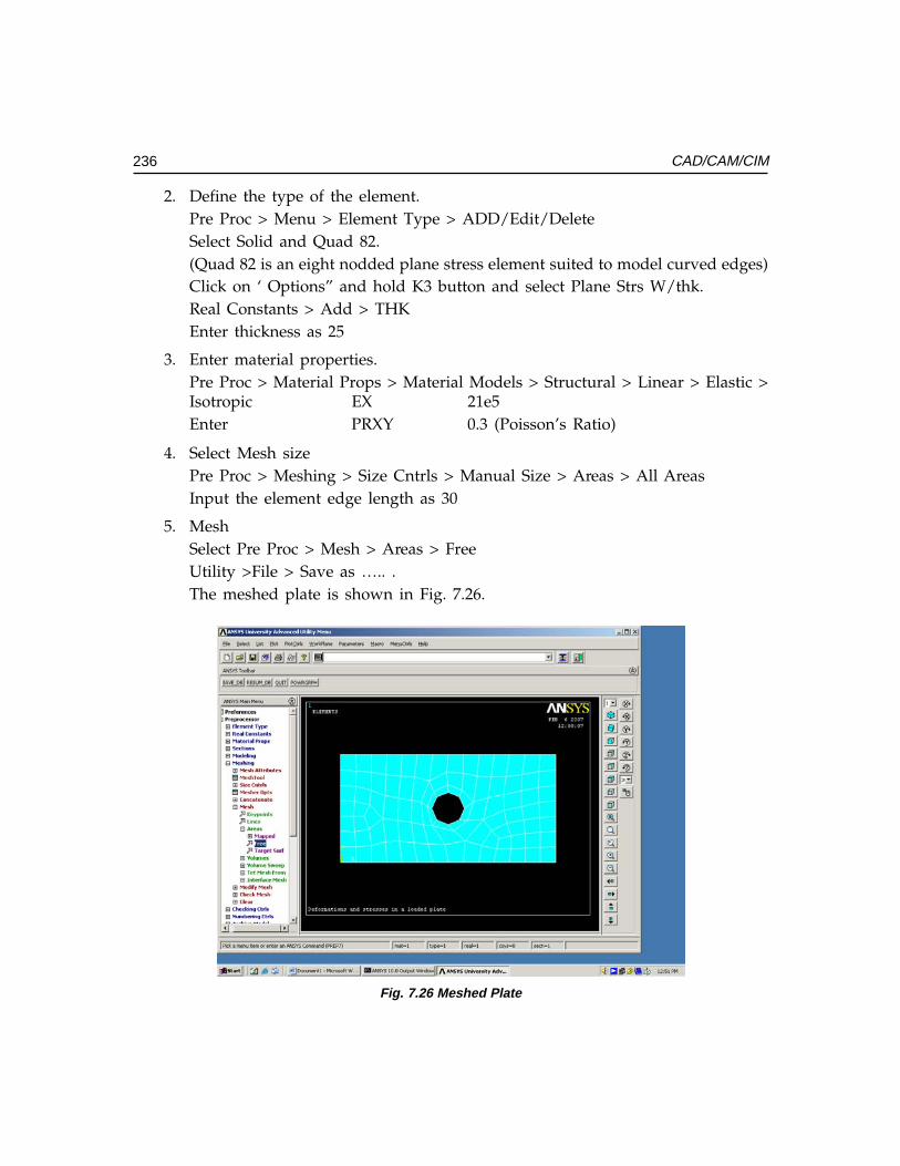
236 CAD/CAM/CIM
2. Define the type of the element.Pre Proc > Menu > Element Type > ADD/Edit/DeleteSelect Solid and Quad 82.(Quad 82 is an eight nodded plane stress element suited to model curved edges)Click on ‘ Options” and hold K3 button and select Plane Strs W/thk.Real Constants > Add > THKEnter thickness as 25
3. Enter material properties.Pre Proc > Material Props > Material Models > Structural > Linear > Elastic >Isotropic EX 21e5Enter PRXY 0.3 (Poisson’s Ratio)
4. Select Mesh sizePre Proc > Meshing > Size Cntrls > Manual Size > Areas > All AreasInput the element edge length as 30
5. MeshSelect Pre Proc > Mesh > Areas > FreeUtility >File > Save as ….. .The meshed plate is shown in Fig. 7.26.
Fig. 7.26 Meshed Plate
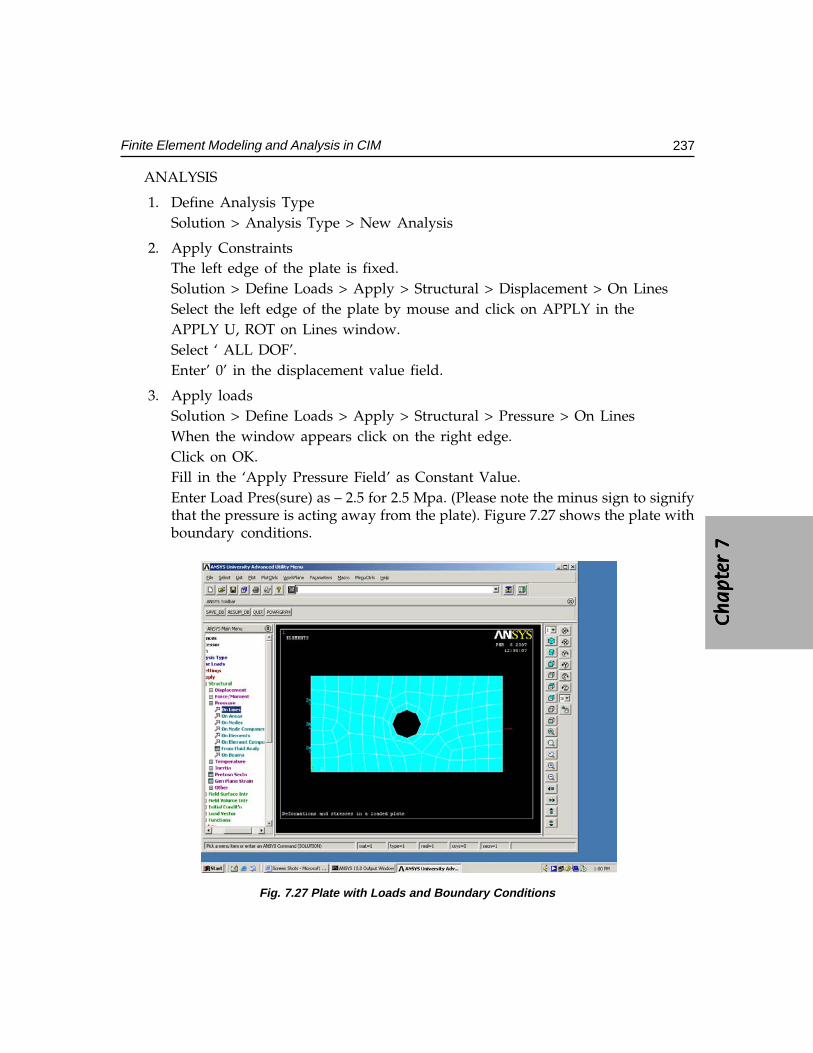
Ch
ap
ter
7C
ha
pte
r 7
Ch
ap
ter
7C
ha
pte
r 7
Ch
ap
ter
7
237Finite Element Modeling and Analysis in CIM
ANALYSIS
1. Define Analysis TypeSolution > Analysis Type > New Analysis
2. Apply ConstraintsThe left edge of the plate is fixed.Solution > Define Loads > Apply > Structural > Displacement > On LinesSelect the left edge of the plate by mouse and click on APPLY in theAPPLY U, ROT on Lines window.Select ‘ ALL DOF’.Enter’ 0’ in the displacement value field.
3. Apply loadsSolution > Define Loads > Apply > Structural > Pressure > On LinesWhen the window appears click on the right edge.Click on OK.Fill in the ‘Apply Pressure Field’ as Constant Value.Enter Load Pres(sure) as – 2.5 for 2.5 Mpa. (Please note the minus sign to signifythat the pressure is acting away from the plate). Figure 7.27 shows the plate withboundary conditions.
�
Fig. 7.27 Plate with Loads and Boundary Conditions
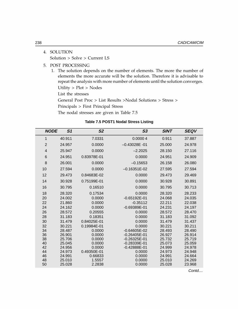
238 CAD/CAM/CIM
4. SOLUTIONSolution > Solve > Current LS
5. POST PROCESSING1. The solution depends on the number of elements. The more the number of
elements the more accurate will be the solution. Therefore it is advisable torepeat the analysis with more number of elements until the solution converges.Utility > Plot > NodesList the stressesGeneral Post Proc > List Results >Nodal Solutions > Stress >Principals > First Principal StressThe nodal stresses are given in Table 7.5
Table 7.5 POST1 Nodal Stress Listing
NODE S1 S2 S3 SINT SEQV
1 40.911 7.0331 0.0000 4 0.911 37.887
2 24.957 0.0000 –0.43028E -01 25.000 24.978
4 25.947 0.0000 –2.2025 28.150 27.116
6 24.951 0.83978E-01 0.0000 24.951 24.909
8 26.001 0.0000 –0.15653 26.158 26.080
10 27.594 0.0000 –0.16351E-02 27.595 27.594
12 29.473 0.84683E-02 0.0000 29.473 29.469
14 30.928 0.75199E-01 0.0000 30.928 30.891
16 30.795 0.16510 0.0000 30.795 30.713
18 28.320 0.17534 0.0000 28.320 28.23320 24.002 0.0000 -0.65192E-01 24.068 24.03522 21.860 0.0000 -0.35112 22.211 22.03824 24.162 0.0000 -0.69389E-01 24.231 24.19726 28.572 0.20555 0.0000 28.572 28.47028 31.183 0.18351 0.0000 31.183 31.09230 31.479 0.84025E-01 0.0000 31.479 31.43732 30.221 0.19984E-01 0.0000 30.221 30.21134 28.487 0.0000 -0.64605E-02 28.493 28.49036 26.901 0.0000 -0.26405E-01 26.927 26.91438 25.706 0.0000 -0.26325E-01 25.732 25.71940 25.045 0.0000 -0.28339E-01 25.073 25.05942 24.956 0.0000 -0.42888E-01 24.999 24.97844 24.973 0.49350E-01 0.0000 24.973 24.94846 24.991 0.66833 0.0000 24.991 24.66448 25.010 1.5557 0.0000 25.010 24.26950 25.028 2.2838 0.0000 25.028 23.968
Contd....
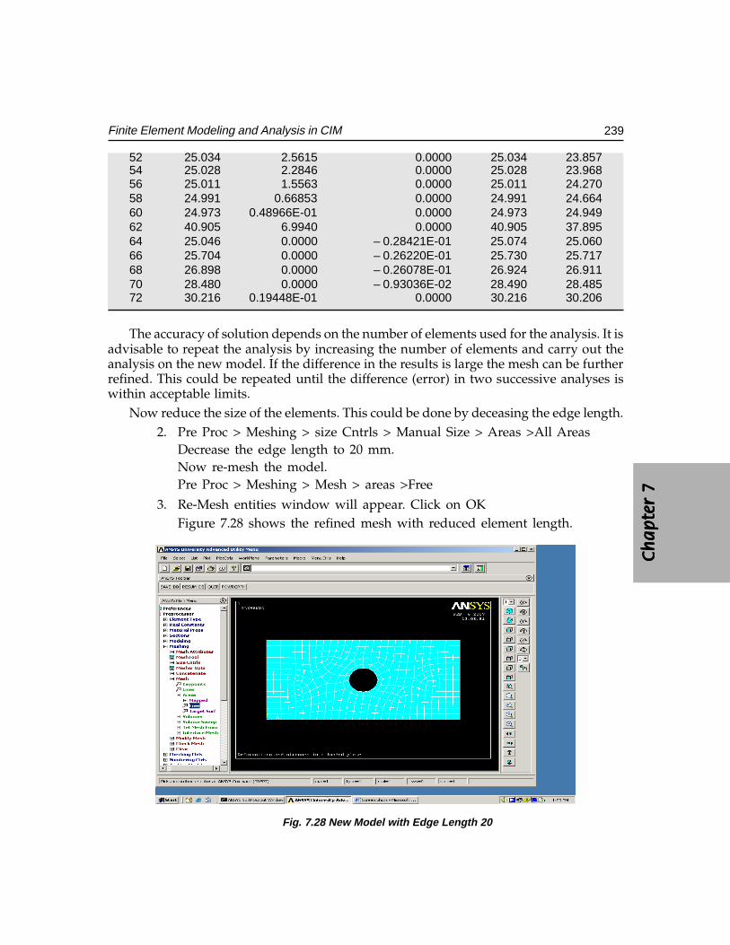
Ch
ap
ter
7C
ha
pte
r 7
Ch
ap
ter
7C
ha
pte
r 7
Ch
ap
ter
7
239Finite Element Modeling and Analysis in CIM
52 25.034 2.5615 0.0000 25.034 23.85754 25.028 2.2846 0.0000 25.028 23.96856 25.011 1.5563 0.0000 25.011 24.27058 24.991 0.66853 0.0000 24.991 24.66460 24.973 0.48966E-01 0.0000 24.973 24.94962 40.905 6.9940 0.0000 40.905 37.89564 25.046 0.0000 – 0.28421E-01 25.074 25.06066 25.704 0.0000 – 0.26220E-01 25.730 25.71768 26.898 0.0000 – 0.26078E-01 26.924 26.91170 28.480 0.0000 – 0.93036E-02 28.490 28.48572 30.216 0.19448E-01 0.0000 30.216 30.206
The accuracy of solution depends on the number of elements used for the analysis. It isadvisable to repeat the analysis by increasing the number of elements and carry out theanalysis on the new model. If the difference in the results is large the mesh can be furtherrefined. This could be repeated until the difference (error) in two successive analyses iswithin acceptable limits.
Now reduce the size of the elements. This could be done by deceasing the edge length.2. Pre Proc > Meshing > size Cntrls > Manual Size > Areas >All Areas
Decrease the edge length to 20 mm.Now re-mesh the model.Pre Proc > Meshing > Mesh > areas >Free
3. Re-Mesh entities window will appear. Click on OKFigure 7.28 shows the refined mesh with reduced element length.
Fig. 7.28 New Model with Edge Length 20
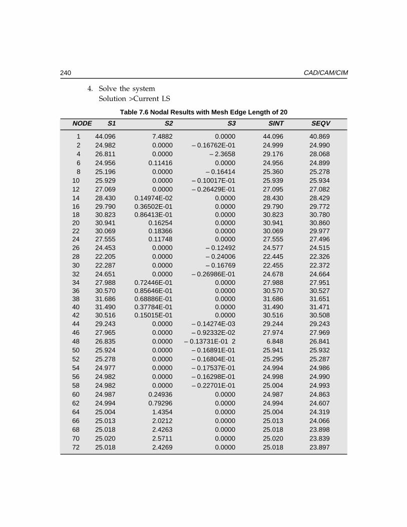
240 CAD/CAM/CIM
4. Solve the systemSolution >Current LS
Table 7.6 Nodal Results with Mesh Edge Length of 20
NODE S1 S2 S3 SINT SEQV
1 44.096 7.4882 0.0000 44.096 40.8692 24.982 0.0000 – 0.16762E-01 24.999 24.9904 26.811 0.0000 – 2.3658 29.176 28.0686 24.956 0.11416 0.0000 24.956 24.8998 25.196 0.0000 – 0.16414 25.360 25.278
10 25.929 0.0000 – 0.10017E-01 25.939 25.93412 27.069 0.0000 – 0.26429E-01 27.095 27.08214 28.430 0.14974E-02 0.0000 28.430 28.42916 29.790 0.36502E-01 0.0000 29.790 29.77218 30.823 0.86413E-01 0.0000 30.823 30.78020 30.941 0.16254 0.0000 30.941 30.86022 30.069 0.18366 0.0000 30.069 29.97724 27.555 0.11748 0.0000 27.555 27.49626 24.453 0.0000 – 0.12492 24.577 24.51528 22.205 0.0000 – 0.24006 22.445 22.32630 22.287 0.0000 – 0.16769 22.455 22.37232 24.651 0.0000 – 0.26986E-01 24.678 24.66434 27.988 0.72446E-01 0.0000 27.988 27.95136 30.570 0.85646E-01 0.0000 30.570 30.52738 31.686 0.68886E-01 0.0000 31.686 31.65140 31.490 0.37784E-01 0.0000 31.490 31.47142 30.516 0.15015E-01 0.0000 30.516 30.50844 29.243 0.0000 – 0.14274E-03 29.244 29.24346 27.965 0.0000 – 0.92332E-02 27.974 27.96948 26.835 0.0000 – 0.13731E-01 2 6.848 26.84150 25.924 0.0000 – 0.16891E-01 25.941 25.93252 25.278 0.0000 – 0.16804E-01 25.295 25.28754 24.977 0.0000 – 0.17537E-01 24.994 24.98656 24.982 0.0000 – 0.16298E-01 24.998 24.99058 24.982 0.0000 – 0.22701E-01 25.004 24.99360 24.987 0.24936 0.0000 24.987 24.86362 24.994 0.79296 0.0000 24.994 24.60764 25.004 1.4354 0.0000 25.004 24.31966 25.013 2.0212 0.0000 25.013 24.06668 25.018 2.4263 0.0000 25.018 23.89870 25.020 2.5711 0.0000 25.020 23.83972 25.018 2.4269 0.0000 25.018 23.897
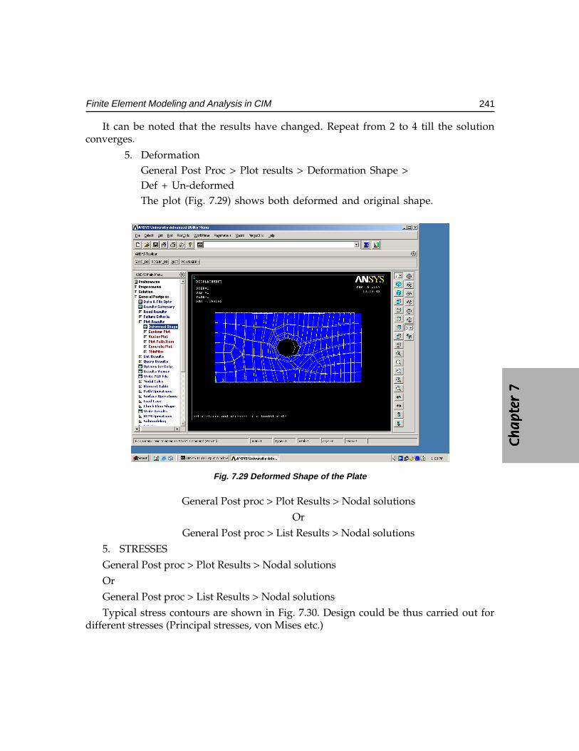
Ch
ap
ter
7C
ha
pte
r 7
Ch
ap
ter
7C
ha
pte
r 7
Ch
ap
ter
7
241Finite Element Modeling and Analysis in CIM
It can be noted that the results have changed. Repeat from 2 to 4 till the solutionconverges.
5. DeformationGeneral Post Proc > Plot results > Deformation Shape >Def + Un-deformedThe plot (Fig. 7.29) shows both deformed and original shape.
Fig. 7.29 Deformed Shape of the Plate
General Post proc > Plot Results > Nodal solutions
Or
General Post proc > List Results > Nodal solutions
5. STRESSES
General Post proc > Plot Results > Nodal solutions
Or
General Post proc > List Results > Nodal solutions
Typical stress contours are shown in Fig. 7.30. Design could be thus carried out fordifferent stresses (Principal stresses, von Mises etc.)
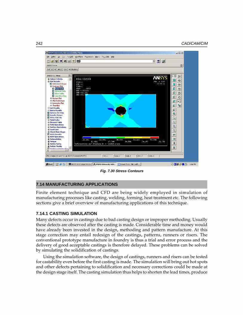
242 CAD/CAM/CIM
7.14 MANUFACTURING APPLICATIONS
Finite element technique and CFD are being widely employed in simulation ofmanufacturing processes like casting, welding, forming, heat treatment etc. The followingsections give a brief overview of manufacturing applications of this technique.
7.14.1 CASTING SIMULATIONMany defects occur in castings due to bad casting design or improper methoding. Usuallythese defects are observed after the casting is made. Considerable time and money wouldhave already been invested in the design, methoding and pattern manufacture. At thisstage correction may entail redesign of the castings, patterns, runners or risers. Theconventional prototype manufacture in foundry is thus a trial and error process and thedelivery of good acceptable castings is therefore delayed. These problems can be solvedby simulating the solidification of castings.
Using the simulation software, the design of castings, runners and risers can be testedfor castability even before the first casting is made. The simulation will bring out hot spotsand other defects pertaining to solidification and necessary corrections could be made atthe design stage itself. The casting simulation thus helps to shorten the lead times, produce
Fig. 7.30 Stress Contours
Ch
ap
ter
7C
ha
pte
r 7
Ch
ap
ter
7C
ha
pte
r 7
Ch
ap
ter
7
243Finite Element Modeling and Analysis in CIM
high quality castings and improve the yield, resulting in lower cost, higher profits andimproved market share. Sand casting, investment casting, permanent mold casting, pressuredie casting and continuous casting of several materials can be analyzed using simulation.These software packages have modules to assist casting designers on proper gating andriser design. The flow of molten metal in the mold cavity can also be simulated. The thermalmodeling capabilities include conduction, convection and radiation. Using simulation itis possible to minimize the defects due to improper flow of molten metal, such as misruns,premature solidification, and oxide formation as well as mold erosion due to excessivevelocity of molten metal during filling.
The simulation programs also may have an optimization module based on criteria likeyield, shrinkage or solidification time.
7.14.2 COMPARISON BETWEEN CONVENTIONAL CASTING APPROACH AND THESIMULATION APPROACH
The conventional casting process is more of a sequential process. At different stages, theengineer encounters problems which make it necessary to go to previous stages for designimprovement or rectification. Corrections after the pattern or die is made are more costly.More important issue is the consequent increase in the development cycle time and theassociated cost overrun. In the CAE approach, the casting design and the casting processare verified through analysis and simulation before the pattern or die is made. Thisconsiderably reduces the development cycle time and costly iterations. Moreover, thecustomers are made happy because of on time delivery of the castings.
7.14.3 CASTING DESIGN SOFTWAREThere are several commercial casting simulation packages available. Some of them arelisted below:
• ProCAST• PASSAGE/PowerCAST• dieCAS• MAGMA• Alphacast-MAVIS FLOW• PAM-CAST• SOLIDCAST,FLOWCAST,OPTICAST
7.15 WELDING SIMULATION
Welding involves very high temperatures to melt the metal in the weld zone whereas themetal at a short distance from the weld pool will be at room temperature. As the weld cools,the residual stresses are produced in the weld zone. These residual stresses induce distortionof the welded structure, which is a major problem the fabricating engineers would like toavoid. The prediction of residual stresses will yield a quantitative understanding of thethermal distortion. The simulation uses a sequentially coupled approach in which a thermal
244 CAD/CAM/CIM
analysis is followed by a stress analysis. The most important phenomenon in welding is heatconduction, which determines the thermal history of the work piece. The thermal historyhas a significant influence on the microstructure and work piece distortion. The convectiveflow of the molten metal in the weld pool is also important in this respect.
There are several software packages available to help the weld planners to determinethe best approach to welding from design to fabrication. A typical simulation covers singlepass welding, multi pass welding, friction welding and friction stir welding. The procedureinvolves modeling the configuration of the weld joint, creation of a global model consistingof the component to be joined by welding, definition of welding sequence and fixturingand finally the calculation of distortion. The analysis of distortion may help to optimizethe process.
A list of welding software packages is given below:
• PAM-Assembly• SORPAS• Virtual Fabrication Technology (VFT)• WELD PRO• CRADA
7.16 FINITE ELEMENT ANALYSIS APPLICATIONS TO METAL FORMING
Metal forming comprises many processes like sheet metal forming (blanking, bending,drawing, stamping, deep drawing, coining, forming etc), extrusion, rolling, forging etc.Forming a sheet metal part usually involves the deformation of the material by either one ora combination of various sheet metal forming processes. Metal forming is a near net shapemanufacturing process and has very wide application in many industries. In particular,sheet metal work involving stamping, drawing and forming is very important activity inautomotive manufacturing. Approach to metal forming earlier was more empirical resultingin considerable trial and error, rework of part design and tooling, wastage and long cycletime in product realization, not to mention about the resultant increase in cost.
FEA based computer simulation software packages for metal forming eliminate thetrial and error approach by allowing rapid modeling of the process at the blue print stageitself, resulting in the reduction of development time and quick turn around of newproducts. The high cost of prototyping, multiple tooling and design iterations, processvariability etc can be substantially reduced, if not entirely eliminated.
Numerical simulation of metal forming operations requires highly complex andaccurate mathematical formulation to model large displacements, rotations, strains andinterfacial friction.
The procedure for simulation of metal forming operations involves generally thefollowing steps:
Ch
ap
ter
7C
ha
pte
r 7
Ch
ap
ter
7C
ha
pte
r 7
Ch
ap
ter
7
245Finite Element Modeling and Analysis in CIM
• Creating a solid model of the component• Developing flat patterns from the solid model in the case of sheet metal parts• Predicting likely manufacturing defects prior to fabrication• Optimize product designs• Determining the most efficient manufacturing process• Arrive at tool parameters• Suggesting solutions for solving manufacturing problems.
There are many software packages available for metal forming simulation. Some ofthem are listed below:
• HyperForm• FemForm• AutoForm• Fastform• HypereXtrude• PAM-STAMP• DEFORM• HyperBlank• LS-DYNA• OPTRIS• Dynaform• MSC.SuperForge• Forge 2D, Forge 3D
7.17 SIMULATION OF HEAT TRATMENT
Important issue in heat treatment is the prediction of residual stresses and distortion. Theheat treatment simulation requires simultaneous modeling of complex physical phenomena:heat transfer, phase transformations, changes in microstructure and mechanics. Thesimulation of heat treatment is very involved because of the complex nature of the constitutivebehavior of the thermo-mechanical properties of the material. Considerable research is beingcarried out to simulate numerous heat treatment processes - case hardening, throughhardening, tempering and annealing. Some software products are already available in themarket. However, there is still considerable scope for development work in this domain.
7.18 PLASTIC INJECTION MOLDING
Plastic injection molding is one application where the finite element technique has beenwidely used for a long time. Mold flow, mold cool, warpage, shrinkage etc could besimulated using a mold analysis software so that the time to market could be considerablyreduced in developing plastic injection molded parts.
246 CAD/CAM/CIM
QUESTIONS
1. Discuss the principle of finite element modeling and analysis for the optimizeddesign of mechanical components.
2. Describe the general steps involved in a finite element analysis.3. Enumerate various types of design problems that could be handled by FEA.4. Distinguish between flexibility and stiffness methods used in FEA.5. Identify two mechanical components each which could be modeled by spring,
spar and beam elements. Justify your answer.6. The truss shown in Fig. 7.8 is manufactured using steel L angles of 50 × 50 × 10 mm
cross section. Other details remaining the same, calculate the stresses in elements 1 and2. Verify your answer using a finite element analysis software.
7. Give some examples of plane stress and plane strain problems in machine design.8. The steel plate shown in Fig. 7.11 has the following dimensions. Length 13 = 800
mm. Length 35 = 1250 mm. A force of 500 N acts on node 5. Develop the stiffnessmatrix and solve for stresses and displacements.
9. Differentiate between isoparametric and non linear elements.10. Why is the assembly procedure of stiffness matrix attached considerable importance?11. Discuss the following with reference to stiffness matrix:
i. Sparse matrixii. Band width
12. What are the capabilities of a typical general purpose FEA package?13. Describe the step by step procedure in solving a design problem using a FEA
package.14. What are the steps involved in creating a pre processing file for the truss shown
in Fig. 7.8 and the plate shown in Fig. 7.11.15. Describe the various approaches to create a finite element model from a solid model.16. Describe the considerations in selecting elements to model the following:
i. Column of a machine toolii. Connecting rod of an engine
iii. Spindle of a latheiv. Flywheel of a diesel engine
17. Analyze the problem given in Fig. 7.24 with different number of elements anddraw a graph percentage error Vs number of elements.
18. Describe the application of finite element technique to simulate:i. Sand Casting
ii. Die Castingiii. Plastic Injection moldingiv. Forming
����������������
����������������
��
������
In a CIM environment the total integration of operations is achieved by a common databaselinking various designs, manufacturing and other related activities. This chapter deals withthe concepts of database and database management system suitable for computer integratedmanufacturing.
8.1 INTRODUCTION
As discussed in the previous sections, Computer Integrated Manufacturing integrates allthe functions related to the manufacture. The following are the major functions amongthem:
i. Computer aided engineering covering design, analysis, simulation andoptimization.
ii. Computer aided manufacturingiii. Operations Managementiv. Logistics, Supply Chain Management, Warehousing and other functions.In the ideal case, all these and their related functions use the same database as shown
in Fig. 8.1. In essence, the successful implementation of CIM lies in the efficient way relevantdata is shared among the different segments of CIM.
The information required for manufacturing is complex covering a wide range ofdisciplines and serving a multitude of inter-related yet vastly differing needs. The CIMdatabase comprises basically four classes of data:
i. PrPrPrPrProduct Data:oduct Data:oduct Data:oduct Data:oduct Data: Data about parts to be manufactured. It includes text and geometrydata.
ii. Manufacturing Data: Manufacturing Data: Manufacturing Data: Manufacturing Data: Manufacturing Data: The information as to how the parts are to be manufacturedis available in production data.
iii. Operational Data:Operational Data:Operational Data:Operational Data:Operational Data: Closely related to manufacturing data but describes the thingsspecific to production, such as lot size, schedule, assembly sequence, qualificationscheme etc.
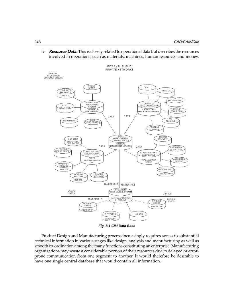
248 CAD/CAM/CIM
iv. ResourResourResourResourResource Data:ce Data:ce Data:ce Data:ce Data: This is closely related to operational data but describes the resourcesinvolved in operations, such as materials, machines, human resources and money.
OPERATIONSMANAGEMENT
SYSTEMPLANNING &
MEASUREMENT
PRODUCTONPLANNING &
CONTROL
ORDERENTRY
COSTACCOUNTING
PURCHASING SHOPFLOOR CONTROL
DATAMANAGEMENT &
COMMUNICATIONS
INTERNALNETWORKING sERVICES
COMPUTER AIDEDMANUFACTURING
PARTSMANUFACURING &
TEST
CNC &DNC
FABRICATING
PRINTEDCIRCUIT BOARDS
MATERIALSHANDLING
ROBOTS
WELDINGPAINTING
ROBOTS
PLASTICMOULDING
CAD
ANALYSIS
NCPROGRAMMING
MOULD/TOOL DESIGN
QCPLANNING
PROCESSPLANNING
COMPUTERAIDED ENGINEERING
ROBOTICASSEMBLY
AUTOMATEDINSPECTION
AUTOMATEDTESTING
PROGRAMMABLE
CONTROLLERS
COMPUTER AIDEDENGINEERING
FINAL ASSEMBLY& TEST
PRODUCT ANDPROCESS ENGINEERING
INTELLIGENTWAREHOUSING SYSTEM
MATERIALS STORAGE& HANDLING
INSPECTION
IN PROCESS
INVENTORY
FINISHEDGOODS
INVENTORY
INCOMINGPARTS
AS & RS
INTE RNAL PUB LIC/P RIVATE NETW O RK S
VENDORPARTS
M AT E R IA L S
SHIPPING
PACKEDGOODS
D ATA
MARKETINFORMATION
CUSTOMER ORDERS
M AT E R IA L S M AT E R IA L S
D ATA
D ATA D ATA
Fig. 8.1 CIM Data Base
Product Design and Manufacturing process increasingly requires access to substantialtechnical information in various stages like design, analysis and manufacturing as well assmooth co-ordination among the many functions constituting an enterprise. Manufacturingorganizations may waste a considerable portion of their resources due to delayed or error-prone communication from one segment to another. It would therefore be desirable tohave one single central database that would contain all information.
Ch
ap
ter
8C
ha
pte
r 8
Ch
ap
ter
8C
ha
pte
r 8
Ch
ap
ter
8
249CIM Data Base and Data Base Management Systems
8.2 DATABASE REQUIREMENTS OF CIM
A major challenge facing the implementation of CIM is to establish the type of data neededto bridge the mechanical design and manufacturing functions. Following is the list ofvaried tasks one might expect to accomplish in a CIM environment.
i. Designing assemblies and performing tolerance analysis on those assemblies.ii. Preparing production drawings of assemblies, individual parts, tooling, fixtures
and other manufacturing facilities.iii. Creating analytical models of parts for structural, kinematical and thermal analysis
(FEM, MeM etc).iv. Calculating weights, volumes, centres of gravity and other mass properties and
costs of manufacturing (cost estimation).v. Classifying existing parts according to shape, function, and the process by which
they are manufactured and retrieving these parts from the parts library on demand(Group technology and coding).
vi. Preparing part lists and bill of materials (BOM).vii. Preparing process plans for individual part manufacture and assembly (Variant
or Generative).viii. Programming CNC machines for processing complete parts (CAM).
ix. Designing work cells and programming the movement of components in thosecells using work handling devices like robots, conveyors, AGV’s/ RGV’s, etc.(Cellular manufacture).
x. Controlling engineering changes and maintaining associativity between designand manufacturing (PDM, VPDM, concurrent associativity etc).
xi. Preparing programs to handle components or manipulate production equipment(like welding torches or robots).
xii. Preparing inspection programs including programs for CNC co-ordinate measuringmachines [CNC CMM’s].
The exchange of graphic information has been advanced with increasing acceptanceof Initial Graphics Exchange Specification (IGES) and STEP.
8.3 DATA BASE
A data base can be defined as a collection of data in a single location designed to be usedby different programmers for a variety of applications. The term database denotes a commonbase of data collection designed to be used by different programmers. More specifically itis a collection of logically related data stored together in a set of files intended to serve oneor more applications in an optimal fashion. Data are stored such that they are independentof the data. A database must also have a predetermined structure and organization suitablefor access, interpretation, or processing either manually or automatically. A database not
250 CAD/CAM/CIM
only stores the data but also provides several ways to view the data depending upon theneeds of the user. There are several classifications of data.
i. Physical data:Physical data:Physical data:Physical data:Physical data: These are data stored in the computer’s storage device. Thevolume of data required by a manufacturing company is so large that secondarystorage devices such as hard discs, tapes, CD-ROMs, and other digital storagedevices of several gigabyte capacities will be used.
ii. Logical data:Logical data:Logical data:Logical data:Logical data: This indicates how a user views the physical data. The distinctionbetween the physical data and the corresponding logical view is that the userconceptualizes certain meaningful relationships among the physical data elements.For example, we may have a set of items and quantities recorded in files. Thelogical view or interpretation of these sets of data can be that the items representcomponents available in stores and that the quantities recorded correspond totheir inventory.
iii. Data independence:Data independence:Data independence:Data independence:Data independence: Database management systems (DBMS) are used by theusers to manage the physical data. DBMS makes a distinction between the twonamely, the user and the physical data. Changes in the organization of physicaldata and or in the storage device parameters are absorbed by DBMS and thereforedo not affect the user or more accurately, the application program. This flexibilityis absent in the traditional file systems.
8.3.1 OBJECTIVES OF DATABASEA database serves the following objectives:
• Reduce or eliminate redundant data• Integrate existing data• Provide security• Share data among users• Incorporate changes quickly and effectively• Exercise effective control over data• Simplify the method of using data• Reduce the cost of storage and retrieval of data• Improve accuracy and integrity of data
8.3.2 ISSUES OF CONCERN IN DATABASEThere are, of course, some issues to be considered while implementing a database. These include:
• High investment in hardware and software• Need to use larger and faster hardware• Necessity to have highly trained manpower
Ch
ap
ter
8C
ha
pte
r 8
Ch
ap
ter
8C
ha
pte
r 8
Ch
ap
ter
8
251CIM Data Base and Data Base Management Systems
• Redundancy to take care of eventualities like crash of the database server.• Need to ensure integrity and reliability of data
8.4 DATABASE MANAGEMENT
The manufacturing database and its management are major issues in CIM. The issues arecomplex but they are beginning to be addressed in a number of ways, including schemesfor organizing data, standards for product data exchange and standards for communicationprotocols. The standards for product data exchange are discussed in chapter 17 andcommunication protocols have been discussed elsewhere. This chapter hence is devotedto the organization of data.
A major problem to be solved to implement CIM has always been that of distributinginformation among different computer based systems. As indicated in earlier chaptersCIM is typically integration of islands of computer aided functions running on differentcomputers using different databases. Joining those islands into an effective CIM enterpriserequires proper methods of processing information. Information, if it is to be useful, mustbe appropriate, machine-interpretable, and available when and where it is needed.
8.5 FEATURES OF A DATABASE MANAGEMENT SYSTEM
A database management system consists of a collection of interrelated data and a set ofprograms to access that data. Database management involves:
• Organize a database.• Add new data to the database.• Sort the data in some meaningful order.• Search the database for types of information.• Print the data into formatted reports.• Edit the data.• Delete the data.
8.5.1 DATABASE ADMINISTRATORThe person responsible for managing the database is often referred to as databaseadministrator. His functions include:
• Creating the primary database structure• Backing up and restoring data in case of crash• Modifying the structure• Transfer data to external files• Allocate and control user access rights• Monitoring performance
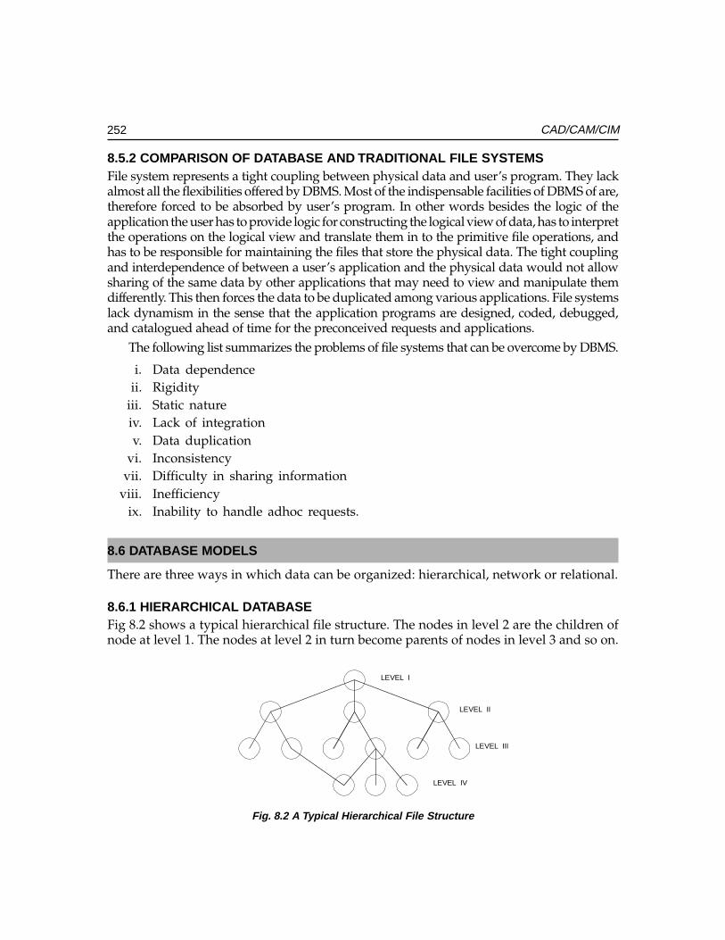
252 CAD/CAM/CIM
8.5.2 COMPARISON OF DATABASE AND TRADITIONAL FILE SYSTEMSFile system represents a tight coupling between physical data and user’s program. They lackalmost all the flexibilities offered by DBMS. Most of the indispensable facilities of DBMS of are,therefore forced to be absorbed by user’s program. In other words besides the logic of theapplication the user has to provide logic for constructing the logical view of data, has to interpretthe operations on the logical view and translate them in to the primitive file operations, andhas to be responsible for maintaining the files that store the physical data. The tight couplingand interdependence of between a user’s application and the physical data would not allowsharing of the same data by other applications that may need to view and manipulate themdifferently. This then forces the data to be duplicated among various applications. File systemslack dynamism in the sense that the application programs are designed, coded, debugged,and catalogued ahead of time for the preconceived requests and applications.
The following list summarizes the problems of file systems that can be overcome by DBMS.
i. Data dependenceii. Rigidity
iii. Static natureiv. Lack of integrationv. Data duplication
vi. Inconsistencyvii. Difficulty in sharing information
viii. Inefficiencyix. Inability to handle adhoc requests.
8.6 DATABASE MODELS
There are three ways in which data can be organized: hierarchical, network or relational.
8.6.1 HIERARCHICAL DATABASEFig 8.2 shows a typical hierarchical file structure. The nodes in level 2 are the children ofnode at level 1. The nodes at level 2 in turn become parents of nodes in level 3 and so on.
LEVEL I
LEVEL II
LEVEL III
LEVEL IV
Fig. 8.2 A Typical Hierarchical File Structure
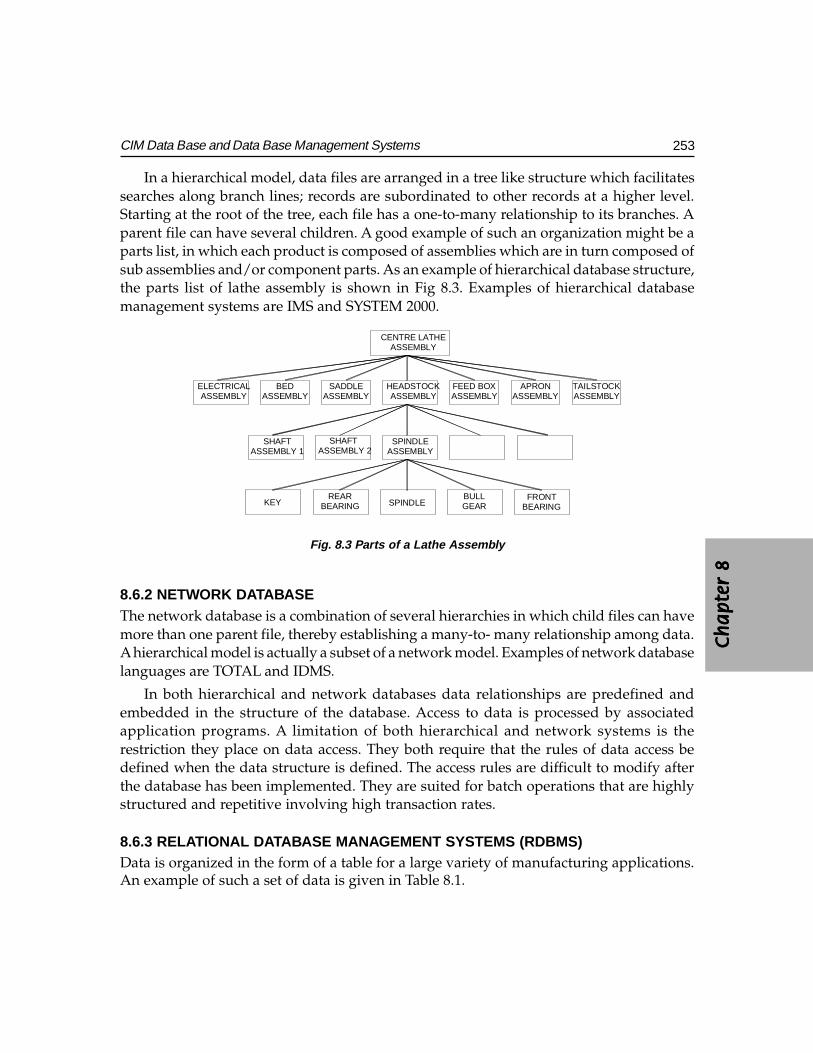
Ch
ap
ter
8C
ha
pte
r 8
Ch
ap
ter
8C
ha
pte
r 8
Ch
ap
ter
8
253CIM Data Base and Data Base Management Systems
In a hierarchical model, data files are arranged in a tree like structure which facilitatessearches along branch lines; records are subordinated to other records at a higher level.Starting at the root of the tree, each file has a one-to-many relationship to its branches. Aparent file can have several children. A good example of such an organization might be aparts list, in which each product is composed of assemblies which are in turn composed ofsub assemblies and/or component parts. As an example of hierarchical database structure,the parts list of lathe assembly is shown in Fig 8.3. Examples of hierarchical databasemanagement systems are IMS and SYSTEM 2000.
HEADSTOCKASSEMBLYASSEMBLY
BEDASSEMBLY
ELECTRICALASSEMBLY
FEED BOXASSEMBLY
APRONASSEMBLY
TAILSTOCKASSEMBLY
CENTRE LATHEASSEMBLY
SADDLE
SHAFTASSEMBLY 1
SHAFT ASSEMBLY 2
SPINDLEASSEMBLY
SPINDLEBULLGEAR
FRONTBEARING
REARBEARINGKEY
Fig. 8.3 Parts of a Lathe Assembly
8.6.2 NETWORK DATABASEThe network database is a combination of several hierarchies in which child files can havemore than one parent file, thereby establishing a many-to- many relationship among data.A hierarchical model is actually a subset of a network model. Examples of network databaselanguages are TOTAL and IDMS.
In both hierarchical and network databases data relationships are predefined andembedded in the structure of the database. Access to data is processed by associatedapplication programs. A limitation of both hierarchical and network systems is therestriction they place on data access. They both require that the rules of data access bedefined when the data structure is defined. The access rules are difficult to modify afterthe database has been implemented. They are suited for batch operations that are highlystructured and repetitive involving high transaction rates.
8.6.3 RELATIONAL DATABASE MANAGEMENT SYSTEMS (RDBMS)Data is organized in the form of a table for a large variety of manufacturing applications.An example of such a set of data is given in Table 8.1.
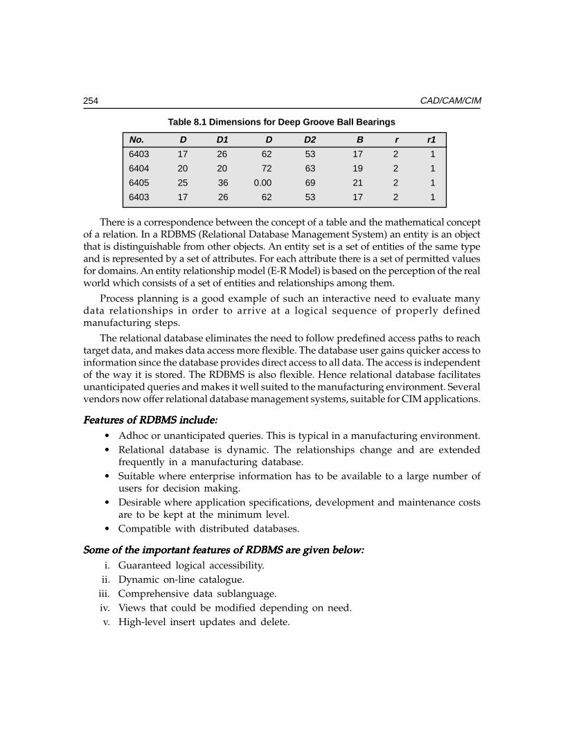
254 CAD/CAM/CIM
Table 8.1 Dimensions for Deep Groove Ball Bearings
No. D D1 D D2 B r r1
6403 17 26 62 53 17 2 1
6404 20 20 72 63 19 2 1
6405 25 36 0.00 69 21 2 1
6403 17 26 62 53 17 2 1
There is a correspondence between the concept of a table and the mathematical conceptof a relation. In a RDBMS (Relational Database Management System) an entity is an objectthat is distinguishable from other objects. An entity set is a set of entities of the same typeand is represented by a set of attributes. For each attribute there is a set of permitted valuesfor domains. An entity relationship model (E-R Model) is based on the perception of the realworld which consists of a set of entities and relationships among them.
Process planning is a good example of such an interactive need to evaluate manydata relationships in order to arrive at a logical sequence of properly definedmanufacturing steps.
The relational database eliminates the need to follow predefined access paths to reachtarget data, and makes data access more flexible. The database user gains quicker access toinformation since the database provides direct access to all data. The access is independentof the way it is stored. The RDBMS is also flexible. Hence relational database facilitatesunanticipated queries and makes it well suited to the manufacturing environment. Severalvendors now offer relational database management systems, suitable for CIM applications.
FeaturFeaturFeaturFeaturFeatures of RDBMS include:es of RDBMS include:es of RDBMS include:es of RDBMS include:es of RDBMS include:
• Adhoc or unanticipated queries. This is typical in a manufacturing environment.• Relational database is dynamic. The relationships change and are extended
frequently in a manufacturing database.• Suitable where enterprise information has to be available to a large number of
users for decision making.• Desirable where application specifications, development and maintenance costs
are to be kept at the minimum level.• Compatible with distributed databases.
Some of the important featurSome of the important featurSome of the important featurSome of the important featurSome of the important features of RDBMS ares of RDBMS ares of RDBMS ares of RDBMS ares of RDBMS are given below:e given below:e given below:e given below:e given below:i. Guaranteed logical accessibility.
ii. Dynamic on-line catalogue.iii. Comprehensive data sublanguage.iv. Views that could be modified depending on need.v. High-level insert updates and delete.
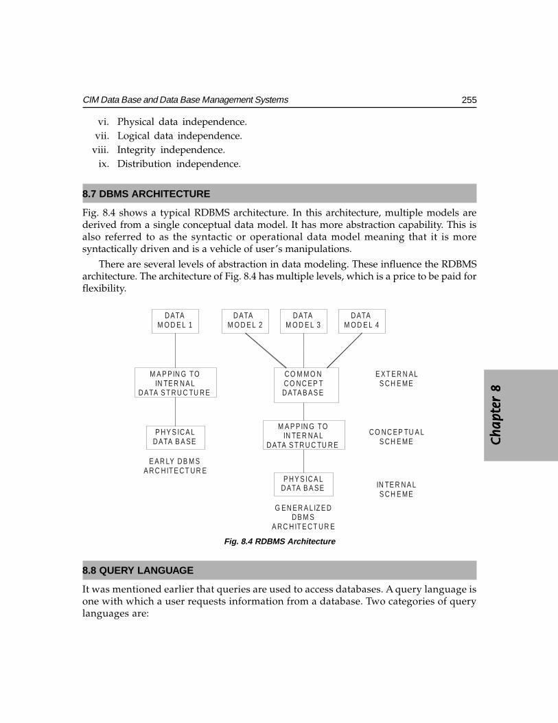
Ch
ap
ter
8C
ha
pte
r 8
Ch
ap
ter
8C
ha
pte
r 8
Ch
ap
ter
8
255CIM Data Base and Data Base Management Systems
vi. Physical data independence.vii. Logical data independence.
viii. Integrity independence.ix. Distribution independence.
8.7 DBMS ARCHITECTURE
Fig. 8.4 shows a typical RDBMS architecture. In this architecture, multiple models arederived from a single conceptual data model. It has more abstraction capability. This isalso referred to as the syntactic or operational data model meaning that it is moresyntactically driven and is a vehicle of user’s manipulations.
There are several levels of abstraction in data modeling. These influence the RDBMSarchitecture. The architecture of Fig. 8.4 has multiple levels, which is a price to be paid forflexibility.
D ATAM O D E L 1
D ATA M O D E L 2
D ATAM O D E L 3
D ATAM O D E L 4
M A P PIN G TOIN TE R N A L
D ATA S T R U C TU R E
P H Y S IC A LD ATA B A SE
A R C H IT E C T U R E
C O M M O NC O N C EP TD ATA B AS E
G EN ER A L IZ E DD B M S
A R C H IT E C T U R E
E XT ER N ALS C H E ME
C O N C EP TU A LS C H E ME
IN TE R N A LS C H E ME
E AR LY D B M S
D ATA S T R U C TU R EIN TE R N A L
M A P PIN G TO
P H Y S IC A LD ATA B A SE
Fig. 8.4 RDBMS Architecture
8.8 QUERY LANGUAGE
It was mentioned earlier that queries are used to access databases. A query language isone with which a user requests information from a database. Two categories of querylanguages are:
256 CAD/CAM/CIM
(i) Procedural(ii) Non-procedural
There are a number of commercial query languages available today. They can beclassified as:
SQL - Structured Query Language
QUEL - Query Language
QBE - Query by Example
The structured query language approach is widely used. The following section presentsa brief overview of SQL.
8.9 STRUCTURED QUERY LANGUAGE [SQL]
The advent and successful implementation of relational databases has brought with itneed for a data base language that is user friendly enough for the common user whilebeing convenient and comfortable for the programmer and applications builder. Thestructured query language now called SQL [pronounced “sequel”], has emerged to fillthis need. The user can easily learn and understand SQL. It can be embedded in a procedurallanguage such as C, COBOL, or PL/l. SQL helps user and programmer to understand therequirements of each other. This fact is very important in making the transition from paperfiles to computerized database systems smooth.
SQL is acronym for Structured Query Language. It is often referred to frequently by itsformer name, Sequel.
The basic structure of an SQL expression consists of three clauses: select, from andwhere.
The static clause corresponds to the projection operation of the relational algebra. It isused to list the attributes desired in the result of a query.
The italic clause is a list of relations to be scanned in the execution of the expression.
The italic clause corresponds to the selection predicate involving attributes of therelations that appear in the ‘from’ clause.
A typical SQL query has the form
Select A1, A2 ... AnFrom rl, r2 ... rmWhere P.
The A’s represent attributes, the r’s represent relations, and the P is a predicate.
SQL forms certain product of the relations named in the ‘from’ clause, performs arelational algebra selection using the where clause predicate.
Ch
ap
ter
8C
ha
pte
r 8
Ch
ap
ter
8C
ha
pte
r 8
Ch
ap
ter
8
257CIM Data Base and Data Base Management Systems
Examples:Examples:Examples:Examples:Examples:
(i) Select Cutting speedFrom cut-dataWhere Material = “C45”And cutting = “Rough turning”And tool = “Carbide”
(ii) Select Feed per toothFrom Mill-dataWhere Material = “Aluminum”And Process = “End Milling”And Cutting = “Rough”
A number of commercial databases now incorporate SQL as their data sub language.
i. IBM System Rii. The Information Management Systems (IMS)
iii. The SQL/Data System (SQL/DS)iv. Database 2(DB2)v. ORACLE
vi. Informixvii. SQLBASE XDB
viii. Ingresix. Sybasex. Progress
8.10 SQL AS A KNOWLEDGE BASE QUERY LANGUAGE
Artificial Intelligence (AI) has wide applications in CIM. Expert Systems constitute animportant field of AI. These systems require extensive knowledge bases to enable sounddecision making. A knowledge base is a database and a set of rules. As such, a knowledgebase is used in the construction of an expert system, which emulates the reasoning of ahuman being in some field of knowledge.
In an expert system, exact answers to the queries posed to the knowledge base are notnecessarily contained within the system. The rules for obtaining an answer provide a meansfor arriving at a conclusion. The conclusion may not necessarily be an absolute answerwith 100 percent certainty. It should have about the same probability of being correct aswould an expert in that field. This contrasts with a database where direct answers to queriesare either contained within the system or are not there at all.
SQL can be used equally well with a database or a knowledge base, and several expertsystems currently exist that use SQL. Like databases, knowledge bases need to be updated
258 CAD/CAM/CIM
from time to time; additional data need to be inserted, as well obsolete or redundant data tobe deleted. The SQL capabilities serve these purposes. However, knowledge bases have anadditional problem in that rules that are added may contradict existing rules. Also, addedrules may simply be extensions or necessary corollaries of existing rules, and therefore maybe redundant. Testing for these problems quickly becomes tedious as the knowledge basegrows large. The expert system called ARITY, developed and sold by Arity Corporation, isan example of the use of SQL to access a knowledge base.
8.11 PRODUCT DATA MANAGEMENT (PDM)
Databases are one component needed to deliver instant, accurate data. Engineeringinformation systems are the other. An engineering data management system shouldautomatically notify members of the design team with updates and circulate latest changeorders. In order to derive maximum benefit from CAD it must be possible to deliver CADdata efficiently and seamlessly to all downstream applications related to engineeringplanning. Product data management is a technology developed to meet this need. PDMsystems work on network layouts called client-server architectures. The server is also calleda vault, even though the information may be distributed over several workstations. Thevault acts as the heart of an engineering network. The vault or the server has the capabilitiesto handle efficiently large amounts of complex information. Product development engineersaccess the vault through their desktop computers called clients.
This client-server idea works efficiently because it runs on two separate, synchronizeddatabases. One database stores product information such as CAD drawings, partspecifications, analysis data, and manufacturing product information. The other database,called a meta database is a relational database that stores information about the data. Forexample given a drawing number this gives information about the attributes of the drawingi.e. where a drawing is stored and when it was last updated etc. The client software letsthe clients talk to the server, allowing design engineers, manufacturing engineers, andmanager’s access to the information stored.
The featurThe featurThe featurThe featurThe features of a PDM system include:es of a PDM system include:es of a PDM system include:es of a PDM system include:es of a PDM system include:• Electronically track, access, sort and retrieve design data enabling the engineers
to work on the most recently updated designs.• Integrating the design environment by providing facilities for viewing drawings
created in different CAD systems like AutoCAD, PRO/E, Unigraphics, CADDS5, I-DEAS, Solid Edge, Solid Works etc.
• Providing a CAD view-and-mark up package to view complete designs on thescreens of the clients so that planning engineers can satisfy themselves thatdesigns are complete before they are released to manufacturing planning.
• Retrieving drawings and designs based on limited information so that designengineers can retrieve already available designs, thereby saving valuable time inproduct development.
Ch
ap
ter
8C
ha
pte
r 8
Ch
ap
ter
8C
ha
pte
r 8
Ch
ap
ter
8
259CIM Data Base and Data Base Management Systems
• Capturing design revision information from a variety of documents like drawings,part lists, bill-of-materials (BOM).
• Providing data security through multi-tier access control.• Creating comprehensive back-up and recovery procedures.• Automatic disk clean-up of old drawing versions and batch back-up.• Generating audit trails such as who designed the part, who modified the part,
who approved the design etc.• Providing graphical user interface tool kits so as to enable the design team to
create new applications.
In short PDM is an excellent tool for concurrent engineering. PDM systems efficientlymanages design reviews by getting the right documents and the drawings to the rightpeople in the quickly. Some of the functions of PDM are discussed in the subsequentsections.
8.11.1 DESIGN REVIEW FUNCTIONTo set up the design review function the project administrator defines each design project,assign the members to the team, describe the actual process and define the workflow. Forexample, in the case of an electric motor design project the tasks to be included may beconceptual design, stress and field analysis, detailed drawings and a description ofmanufacturing and assembly process. One task, for example, the design analysis will becarried out by a group of three and approved by one. The design may have to be acceptedby all the members of the group. The design review system gives considerable flexibilityfor the persons in charge of the project.
8.11.2 CHANGE MANAGEMENTThe project administrator develops the process that handles engineering change orders. Asignificant change management feature is the protection of engineering changes-in-progressfrom implemented too soon or by accident. This also eliminates paper work.
8.11.3 WHERE-USED REPORTSThis is another function of PDM. The software answers the question, “Which assemblyuses component A?”. PDM produces a report which shows component-by-componentbreakdown of the complete assembly with the “where-used” components highlighted.
8.11.4 CONFIGURATION MANAGEMENTThe configuration management function is also called product-structure management. Thisshows how the parts in an assembly relate to one another. This provides an opportunityfor the product administrators to create standards for handling bill-of-material partrelationships and for defining product life-cycle data requirements. For example, the graphicdisplay from a configuration management application will show the hierarchy of
260 CAD/CAM/CIM
automobile body parts, starting with body, doors, wheels and tyres. This will be furtherbroken down to the last nut and bolt. Each component will be described in several ways toshow the use and assembly inter-relationships.
8.12 ADVANTAGES OF PDM
PDM offers several benefits for the speedy execution of product development projects:
• PDM helps engineers to access design drawings in minutes.• Managers know how many drawings were released for fabrication.• Manufacturing engineers know exactly when to start fabrication.• Two designers cannot simultaneously edit the same drawing.• Two drawings cannot have the same drawing numbers.• All information from drawing-release statistics to revision details pass to the
primary project management system that tracks overall project status for all thecompany activities.
• The PDM system keeps a complete history of the modifications, when themodifications took place and keeps all previous versions of data for a perioddefined by the company.
• Subcontractors can be given direct access to PDM database. Controls ensure thatno subcontractor can access data associated with the sub-sets of projects he is notinvolved with.
QUESTIONS
1. Prepare a chart showing the data required and data generated in the varioussegments of a manufacturing industry?
2. What is a database?3. What are the objectives of a database?4. What are the disadvantages of a database?5. How does the conventional file system differ from a database?6. What are the four classes of data in manufacturing?7. What are the desirable features of a database management system?8. Describe the three database models.9. Study typical data in a factory and analyze how you can classify the data.
10. What is a relational database? Give an example.11. Describe the architecture of a database management system?12. What are the essential requirements of a relational database management system?13. What is a query language? What are the major types of query language?14. What is SQL?

Ch
ap
ter
8C
ha
pte
r 8
Ch
ap
ter
8C
ha
pte
r 8
Ch
ap
ter
8
261CIM Data Base and Data Base Management Systems
15. Give an example of the use of SQL to access a database?16. What is the role of PDM in drawing office management?17. What are the features of PDM which help speedy product development?18. What are the benefits of PDM?

This pageintentionally left
blank
�������������
����� �������
������
Once the design of a component is over, the planning phase of manufacturing commences.The first task in planning is the design of the processes. Process planning is a vital linkbetween design and manufacturing functions. This is an important task as the cost of thepart depends on the process. One of the active research areas in CIM is computer aidedprocess planning. This chapter deals with the use of computers for process design.
9.1 INTRODUCTION
Process planning is concerned with determining the sequence of individual manufacturingoperations needed to produce a given part or product. The resulting operation sequence isdocumented on a form typically referred to as operation sheet. The operation sheet is alisting of the production operations and associated machine tools for a work part orassembly. Process planning is an important stage of product development since productiontooling like jigs, fixtures, special tools etc. can be designed only after the process is finalized.
Like a group technology - based system utilizing classification and coding to retrieveparts, code numbers can be used for retrieval of existing and preferred manufacturinginformation. The principle of group technology is therefore discussed here as part of processplanning. The importance of process planning lies in the fact that process plans have adirect bearing on the cost of the part. As new manufacturing processes and machines areintroduced, process plans also undergo changes. Hence process planning is a dynamicactivity. The continuous emphasis on cost reduction also requires the process plans to beupdated to reduce the cost. Cost information can be included in a computer assisted processplanning system, using an automatic time standards (ATS) system.
9.2 PROCESS PLANNING
Manufacturing planning, process planning, material processing, process engineering andmachine routing are a few titles given to the topic referred to here as process planning.
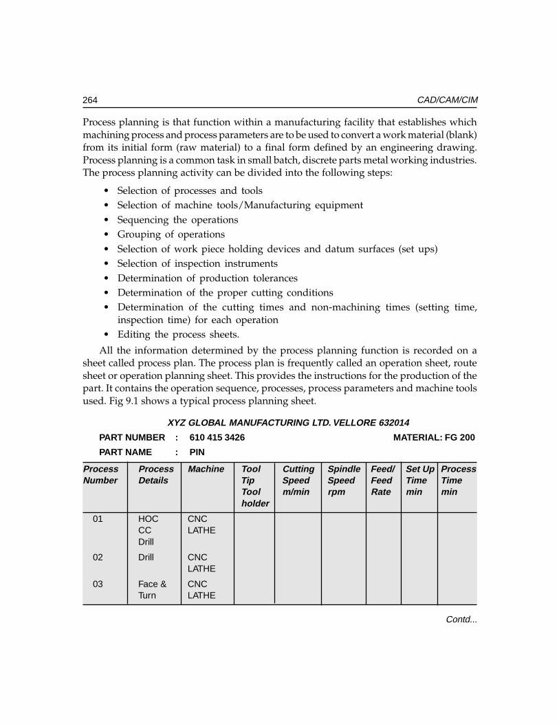
264 CAD/CAM/CIM
Process planning is that function within a manufacturing facility that establishes whichmachining process and process parameters are to be used to convert a work material (blank)from its initial form (raw material) to a final form defined by an engineering drawing.Process planning is a common task in small batch, discrete parts metal working industries.The process planning activity can be divided into the following steps:
• Selection of processes and tools• Selection of machine tools/Manufacturing equipment• Sequencing the operations• Grouping of operations• Selection of work piece holding devices and datum surfaces (set ups)• Selection of inspection instruments• Determination of production tolerances• Determination of the proper cutting conditions• Determination of the cutting times and non-machining times (setting time,
inspection time) for each operation• Editing the process sheets.
All the information determined by the process planning function is recorded on asheet called process plan. The process plan is frequently called an operation sheet, routesheet or operation planning sheet. This provides the instructions for the production of thepart. It contains the operation sequence, processes, process parameters and machine toolsused. Fig 9.1 shows a typical process planning sheet.
XYZ GLOBAL MANUFACTURING LTD. VELLORE 632014
PART NUMBER : 610 415 3426 MATERIAL: FG 200
PART NAME : PIN
Process Process Machine Tool Cutting Spindle Feed/ Set Up ProcessNumber Details Tip Speed Speed Feed Time Time
Tool m/min rpm Rate min minholder
01 HOC CNCCC LATHEDrill
02 Drill CNCLATHE
03 Face & CNCTurn LATHE
Contd...
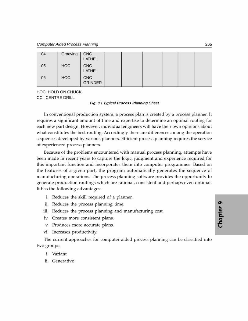
Ch
ap
ter
9C
ha
pte
r 9
Ch
ap
ter
9C
ha
pte
r 9
Ch
ap
ter
9
265Computer Aided Process Planning
04 Grooving CNCLATHE
05 HOC CNCLATHE
06 HOC CNCGRINDER
HOC: HOLD ON CHUCKCC : CENTRE DRILL
Fig. 9.1 Typical Process Planning Sheet
In conventional production system, a process plan is created by a process planner. Itrequires a significant amount of time and expertise to determine an optimal routing foreach new part design. However, individual engineers will have their own opinions aboutwhat constitutes the best routing. Accordingly there are differences among the operationsequences developed by various planners. Efficient process planning requires the serviceof experienced process planners.
Because of the problems encountered with manual process planning, attempts havebeen made in recent years to capture the logic, judgment and experience required forthis important function and incorporates them into computer programmes. Based onthe features of a given part, the program automatically generates the sequence ofmanufacturing operations. The process planning software provides the opportunity togenerate production routings which are rational, consistent and perhaps even optimal.It has the following advantages:
i. Reduces the skill required of a planner.
ii. Reduces the process planning time.
iii. Reduces the process planning and manufacturing cost.
iv. Creates more consistent plans.
v. Produces more accurate plans.
vi. Increases productivity.
The current approaches for computer aided process planning can be classified intotwo groups:
i. Variant
ii. Generative
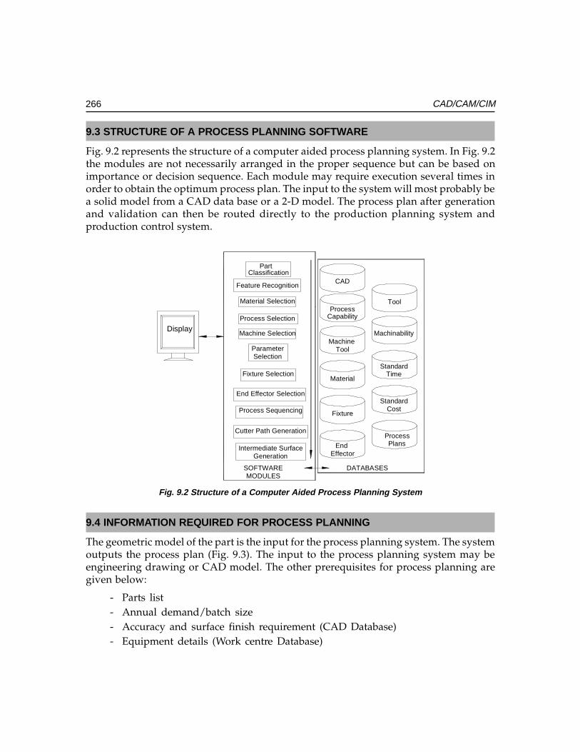
266 CAD/CAM/CIM
9.3 STRUCTURE OF A PROCESS PLANNING SOFTWARE
Fig. 9.2 represents the structure of a computer aided process planning system. In Fig. 9.2the modules are not necessarily arranged in the proper sequence but can be based onimportance or decision sequence. Each module may require execution several times inorder to obtain the optimum process plan. The input to the system will most probably bea solid model from a CAD data base or a 2-D model. The process plan after generationand validation can then be routed directly to the production planning system andproduction control system.
DATABASESMODULES
SOFTWARE
Part
PlansProcess
EffectorEnd
Fixture
Material
Tool
ToolMachine
CapabilityProcess
CAD
GenerationIntermediate Surface
Cutter Path Generation
Process Sequencing
End Effector Selection
Fixture Selection
Machine Selection
Process Selection
Material Selection
Feature Recognition
CostStandard
TimeStandard
Machinability
SelectionParameter
Classification
Display
Fig. 9.2 Structure of a Computer Aided Process Planning System
9.4 INFORMATION REQUIRED FOR PROCESS PLANNING
The geometric model of the part is the input for the process planning system. The systemoutputs the process plan (Fig. 9.3). The input to the process planning system may beengineering drawing or CAD model. The other prerequisites for process planning aregiven below:
- Parts list- Annual demand/batch size- Accuracy and surface finish requirement (CAD Database)- Equipment details (Work centre Database)
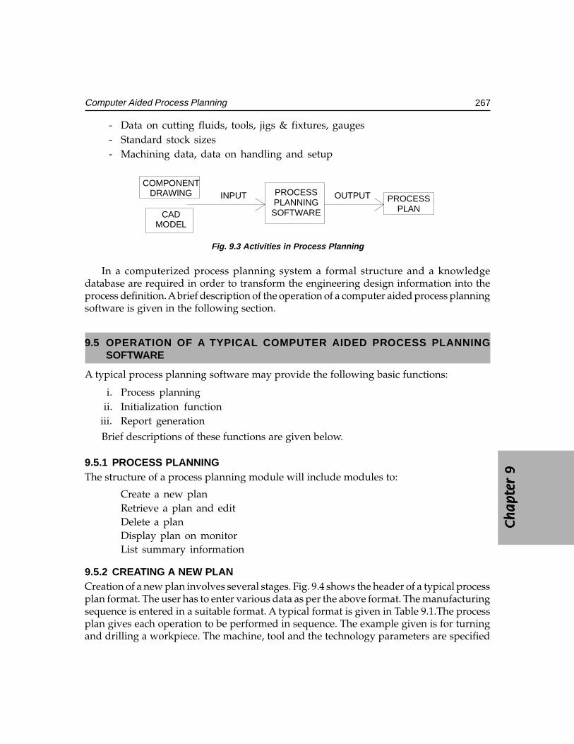
Ch
ap
ter
9C
ha
pte
r 9
Ch
ap
ter
9C
ha
pte
r 9
Ch
ap
ter
9
267Computer Aided Process Planning
- Data on cutting fluids, tools, jigs & fixtures, gauges- Standard stock sizes- Machining data, data on handling and setup
PLANPROCESSOUTPUT
SOFTWAREPLANNINGPROCESSINPUT
MODELCAD
DRAWINGCOMPONENT
Fig. 9.3 Activities in Process Planning
In a computerized process planning system a formal structure and a knowledgedatabase are required in order to transform the engineering design information into theprocess definition. A brief description of the operation of a computer aided process planningsoftware is given in the following section.
9.5 OPERATION OF A TYPICAL COMPUTER AIDED PROCESS PLANNINGSOFTWARE
A typical process planning software may provide the following basic functions:
i. Process planningii. Initialization function
iii. Report generation
Brief descriptions of these functions are given below.
9.5.1 PROCESS PLANNINGThe structure of a process planning module will include modules to:
Create a new planRetrieve a plan and editDelete a planDisplay plan on monitorList summary information
9.5.2 CREATING A NEW PLANCreation of a new plan involves several stages. Fig. 9.4 shows the header of a typical processplan format. The user has to enter various data as per the above format. The manufacturingsequence is entered in a suitable format. A typical format is given in Table 9.1.The processplan gives each operation to be performed in sequence. The example given is for turningand drilling a workpiece. The machine, tool and the technology parameters are specified
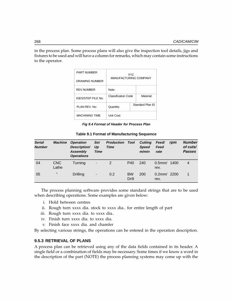
268 CAD/CAM/CIM
in the process plan. Some process plans will also give the inspection tool details, jigs andfixtures to be used and will have a column for remarks, which may contain some instructionsto the operator.
Unit Cost:
Standard Plan IDQuantity:
Material:Classification Code
Note:
MANUFACTURING COMPANYXYZ
MACHINING TIME
PLAN REV. No:
IGES/STEP FILE No:
REV.NUMBER
DRAWING NUMBER
PART NUMBER
Fig 9.4 Format of Header for Process Plan
Table 9.1 Format of Manufacturing Sequence
Serial Machine Operation Set Production Tool Cutting Feed/ rpm NumberNumber Description/ Up Time Speed Feed of cuts/
Assembly Time m/min rate PassesOperations
04 CNC Turning - 2 P40 240 0.5mm/ 1400 4Lathe rev.
05 ” Drilling - 0.2 BW 200 0.2mm/ 2200 1Drill rev.
The process planning software provides some standard strings that are to be usedwhen describing operations. Some examples are given below:
i. Hold between centresii. Rough turn xxxx dia. stock to xxxx dia.. for entire length of part
iii. Rough turn xxxx dia. to xxxx dia..iv. Finish turn xxxx dia. to xxxx dia.v. Finish face xxxx dia. and chamfer
By selecting various strings, the operations can be entered in the operation description.
9.5.3 RETRIEVAL OF PLANSA process plan can be retrieved using any of the data fields contained in its header. Asingle field or a combination of fields may be necessary. Some times if we know a word inthe description of the part (NOTE) the process planning systems may come up with the
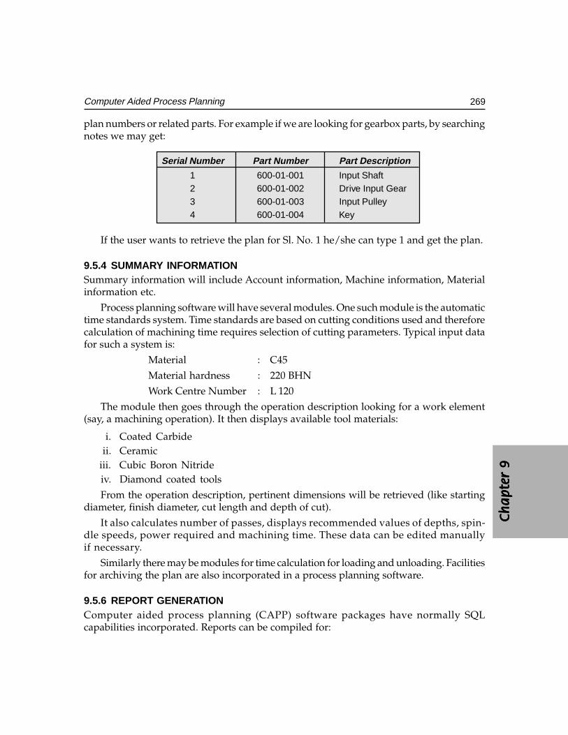
Ch
ap
ter
9C
ha
pte
r 9
Ch
ap
ter
9C
ha
pte
r 9
Ch
ap
ter
9
269Computer Aided Process Planning
plan numbers or related parts. For example if we are looking for gearbox parts, by searchingnotes we may get:
Serial Number Part Number Part Description
1 600-01-001 Input Shaft2 600-01-002 Drive Input Gear3 600-01-003 Input Pulley4 600-01-004 Key
If the user wants to retrieve the plan for Sl. No. 1 he/she can type 1 and get the plan.
9.5.4 SUMMARY INFORMATIONSummary information will include Account information, Machine information, Materialinformation etc.
Process planning software will have several modules. One such module is the automatictime standards system. Time standards are based on cutting conditions used and thereforecalculation of machining time requires selection of cutting parameters. Typical input datafor such a system is:
Material : C45
Material hardness : 220 BHN
Work Centre Number : L 120
The module then goes through the operation description looking for a work element(say, a machining operation). It then displays available tool materials:
i. Coated Carbideii. Ceramic
iii. Cubic Boron Nitrideiv. Diamond coated tools
From the operation description, pertinent dimensions will be retrieved (like startingdiameter, finish diameter, cut length and depth of cut).
It also calculates number of passes, displays recommended values of depths, spin-dle speeds, power required and machining time. These data can be edited manuallyif necessary.
Similarly there may be modules for time calculation for loading and unloading. Facilitiesfor archiving the plan are also incorporated in a process planning software.
9.5.6 REPORT GENERATIONComputer aided process planning (CAPP) software packages have normally SQLcapabilities incorporated. Reports can be compiled for:
270 CAD/CAM/CIM
i. Parts with identical classification
ii. Parts using specific machine type
iii. Parts machined using specific tool materials
iv. Bill of materials
9.6 CAD BASED PROCESS PLANNING - CERTAIN LIMITATIONS AND PROBLEMS
The geometric model of an object is represented by a set of data. The data consists of numericalvalues, names, codes and symbols. The data are stored in computer memory in an organizedmanner. This organization represents the relationship of each data element to other elements.Included in this relationship is the topological relationship of the surface geometry.
The common methods of geometric modeling in use today are:
i. 2-D modelingii. Surface modeling
iii. Solid modelingThe techniques of these methods have been discussed in earlier chapters. The creation
of process for CNC machining is discussed in Chapter 12. This chapter concentrates ongeneral process design.
With the taxonomy of graphical representation described by above procedures, somegeneral problems of part representation systems can be identified. These problems include:
i. The inability to represent special manufacturing techniques like coatings andsurface treatment.
ii. Lack of data interchange between some drafting representations. Since there isno easy way to identify surfaces requiring machining using any of the geometricrepresentations mentioned previously, the best solution is to use a human-computerinteractive system to identify the surface.
In order to use a CAD system as the front end for computer aided process planning,the following capabilities are required.
i. Location and interactive identification of lines and surfaces.ii. Easy dimension retrieval.
iii. Storage and retrieval of tolerance information.iv. Capability of displaying multiple objects.v. Built- in special tags (i.e., drill angle for hole).
vi. Combining information on special processes like heat treatment, surface treatmentand surface finishing techniques with the geometric model.
The addition of automatic feature recognition (AFR) software has made the processplanning task considerably easy. CAD software which incorporates this feature highlights
Ch
ap
ter
9C
ha
pte
r 9
Ch
ap
ter
9C
ha
pte
r 9
Ch
ap
ter
9
271Computer Aided Process Planning
individual machining feature one by one. The process planner can then interactivelydefine the processes or check if any feature has been left out while creating an automaticprocess plan.
The recent developments in modeling technologies and detailing procedures havehelped designers to incorporate auxiliary information like geometric tolerances. Theseadditions have improved the quality of process plans created by CAPP.
In the case of precision components, the process design can be extremely complex.This is particularly so when we consider components with accuracies of the order of a fewmicrometers and surface finishes at sub micrometer level. Further, the need to achieve therequired concentricity, parallelism and perpendicularity etc. requires very careful designof the processes. Such extra precision components will have high rejection levels. Processdesign even by experienced planners may have to undergo several modifications to realizethe ultimate product. The inability to model the dynamics of machine tool - material –work piece - fixture system is still a major bottleneck in manufacturing. Further, the physicaland metallurgical behavior of the work material and the non-deterministic nature of toolwear may necessitate modifications to process plans. Tolerance accumulation in machinedcomponents is another major problem.
One of the convenient ways in which process plans can be created for a component is bysearching for the availability of similar components in the component database. The similaritycan be in geometry, tolerances, materials and processes. If a similar component is available it islikely that their manufacturing process is also proven. In that case it is reasonable to use theprocess plan with whatever modifications that may be necessary rather than creating a newprocess plan. Automatic process planning tends to be more successful if such a “variant”approach is adopted. This requires an efficient method of retrieval based on a suitableidentification number. Codes based on group technology provide unique identification forpart families. Group technology is known and practiced for the last three decades or more inbatch manufacturing industries and it is a convenient tool for classifying and codingcomponents, machined components, components made of sheet metal etc. The followingsections give a brief introduction to this technology and its uses in CAPP.
Both geometric modeling and drafting are detailed representation of an engineeringdesign. They provide information concerning the component to be made, and are essentialin conveying the design intent to the manufacturing personnel.
However, as with many decision making processes, too much information may makearriving at decisions difficult. Thus, for the purpose of process plan retrieval, the grouptechnology technique can be used to code a component without considering its finer details.
There are two types of information that are required by a process planning system:
i. Design features of the component.ii. Process knowledge/economic alternatives/information of materials/process
equipment.
272 CAD/CAM/CIM
9.7 GROUP TECHNOLOGY
Group technology is an operations management philosophy based on the recognition thatsimilarities occur in the design and manufacture of discrete parts. Similar parts can thenbe arranged into part families. To implement such a system, some form of classification ofparts and coding is required.
Part classification and coding is concerned with identifying the similarities and usingthese similarities to evolve a classification code. Similarities are of two types: designattributes (such as geometric shape and size), and manufacturing attributes (the sequenceof processing steps required to make the part).
In companies which employ several design engineers and manufacturing a diverserange of products, such classifications and coding has a number of other uses. One of themajor benefits is avoiding the duplication of similar components. This can result inconsiderable savings in terms of design cost, processing cost and tooling cost. One primenecessity to realize this is to have a good design retrieval system.
The parts classification and coding is required in a design retrieval system, and incomputer aided process planning the process routing is developed by recognizing thespecific attributes of the part and relating these attributes to the correspondingmanufacturing operations.
9.7.1 PART FAMILIESA part family is a collection of parts which are similar either because of geometry and sizeor because similar processing steps are required in their manufacture. The parts within afamily are different, but their similarities are close enough to merit their identification asmembers of the part family. The major obstacle in changing over to group technologyfrom a traditional production shop is the problem of grouping parts into families. Thereare three general methods for solving this problem.
i. Visual inspectionii. Production flow analysis
iii. Parts classification and coding system
What is desirable in a computer integrated manufacturing environment is a softwarewhich will analyze the geometric model of the part and come out with a set of alphabetic/numeric characters which can broadly embed similarities.
9.7.2 PARTS CLASSIFICATION AND CODING SYSTEMSParts classification and coding systems can be grouped into three general types:
i. Systems based on design attributesii. Systems based on part manufacturing attributes
iii. Systems based on both design and manufacturing attributes
Ch
ap
ter
9C
ha
pte
r 9
Ch
ap
ter
9C
ha
pte
r 9
Ch
ap
ter
9
273Computer Aided Process Planning
Systems in the first category are useful for design retrieval and to promote designstandardization. Systems in the second category are used for computer-aided processplanning, tool design, and other production related functions. The third category representsan attempt to combine the functions and advantages of the other two systems into a singleclassification scheme. The types of design and manufacturing attributes typically includedin classification schemes are listed below:
Part Design Part Design Part Design Part Design Part Design AttributesAttributesAttributesAttributesAttributesBasic (External/Internal) shapeAxisymmetric/Prismatic/sheet metalLength/diameter ratioMaterialMajor dimensionsMinor dimensionsTolerancesSurface finish
Part Manufacturing Part Manufacturing Part Manufacturing Part Manufacturing Part Manufacturing AttributesAttributesAttributesAttributesAttributesMajor process of manufactureSurface treatments/coatingsMachine tool/processing equipmentCutting toolsOperation sequenceProduction timeBatch quantityProduction rateFixtures needed
If we take a look at a machine tool manufacturing industry, large part families can begrouped as:
i. Heavy parts - beds, columns etc.ii. Shafts, characterized by large L/D ratios
iii. Spindles (long shafts, screw rods included)iv. Non-rounds (small prismatic parts)v. Gears, disc type parts (whose L/D ratios are small)
From the manufacturing point of view, group technology can bring in considerableeconomy in tooling, set up time, part changeover times, machine specifications etc. Theclassification of components in groups can lead to formation of cells where similarcomponents are machined. However, these considerations are extraneous to the processplanning function.
274 CAD/CAM/CIM
9.8 CODING STRUCTURES
A part coding scheme consists of symbols that identify the part’s design and/ormanufacturing attributes. The symbols in the code can be all numeric, all alphabetic, ora combination of both types. There are three basic code structures used in grouptechnology applications:
i. Hierarchical structureii. Chain type structure
iii. Hybrid structure which is a combination of the above two
With the hierarchical structure, the interpretation of each succeeding symbol dependson the value of the preceding symbols. In the chain type structure, the interpretation ofeach symbol in the sequence is fixed and does not depend on the value of preceding digits.Most of the commercial parts coding systems are used in industry are a combination of thetwo pure structures.
When selecting a coding system for a component’s representation, there are severalfactors to be considered. They include:
i. The geometry of components (i.e., rotational, prismatic, deep drawn, sheet metaletc.)
ii. The code structureiii. The digital representation (i.e., binary, octal, hexadecimal etc.)iv. Material of manufacture - ferrous, non ferrous, plastics, composites etc.
When using a code to represent an engineering design, it is important to represent thebasic features of the design. For process planning, it is desirable to have codes that candistinguish unique production families.
Some of the coding systems that have been successfully implemented in processplanning are given below:
i. OPITZ systemii. The CODE system
iii. The KK-3 systemiv. The MICLASS systemv. DCLASS system
vi. COFORM (coding for machining)
When implementing a parts classification and coding system, most companiescan purchase a commercially available package or develop a system for their ownspecific use.
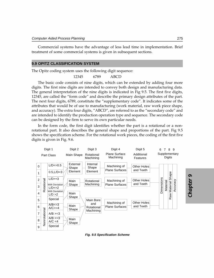
Ch
ap
ter
9C
ha
pte
r 9
Ch
ap
ter
9C
ha
pte
r 9
Ch
ap
ter
9
275Computer Aided Process Planning
Commercial systems have the advantage of less lead time in implementation. Brieftreatment of some commercial systems is given in subsequent sections.
9.9 OPITZ CLASSIFICATION SYSTEM
The Opitz coding system uses the following digit sequence:
12345 6789 ABCD
The basic code consists of nine digits, which can be extended by adding four moredigits. The first nine digits are intended to convey both design and manufacturing data.The general interpretation of the nine digits is indicated in Fig 9.5. The first five digits,12345, are called the “form code” and describe the primary design attributes of the part.The next four digits, 6789, constitute the “supplementary code”. It indicates some of theattributes that would be of use to manufacturing (work material, raw work piece shape,and accuracy). The extra four digits, “ABCD”, are referred to as the “secondary code” andare intended to identify the production operation type and sequence. The secondary codecan be designed by the firm to serve its own particular needs.
In the form code, the first digit identifies whether the part is a rotational or a non-rotational part. It also describes the general shape and proportions of the part. Fig 9.5shows the specification scheme. For the rotational work pieces, the coding of the first fivedigits is given in Fig. 9.6.
9876
DigitsSupplementary
FeaturesAdditional
Digit 5
MachiningPlane Surface
Digit 4
MachiningRotational
Digit 3
Main Shape
Digit 2
Part Class
Digit 1
Rot
atio
nal
Non
rota
tiona
l
Acc
urac
yR
aw M
ater
ial S
hape
Mat
eria
l
Dim
ensi
ons
Other Holesand Teeth
Other Holesand Teeth
and TeethOther Holes
Plane SurfacesMachining of
Plane SurfacesMachining of
Plane SurfacesMachining of
MachiningRotational
andMain Bore
MachiningRotational
ElementShapeInternal
MainShape
MainShape
MainShape
ShapeMain
ElementShapeExternal
SpecialA/C <4A/B <=3A/B >=3
A/C>=4A/B<=3
Special
L/D >2With DeviationL/D<=2
With Deviation
L/D>=3
0.5,L/D<3
L/D<=0.5
9
8
7
6
5
4
3
2
1
0
Fig. 9.5 Specification Scheme
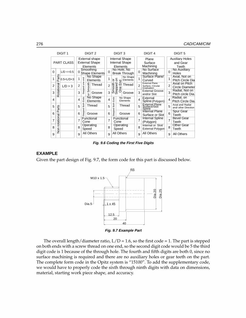
276 CAD/CAM/CIM
L/D > 3
0.5<L/D<3
L/D <=0.5
or S
moo
th
DIGIT 5DIGIT 4DIGIT 3DIGIT 2DIGIT 1
All Others
Pitch Circle Dia.Radial, on
TeethOther GearTeethBevel GearTeethSpur Gearand/ other DirectionAxial and/ Radial
Pitch circle Dia.Radial, Not onCircle DiameterAxial on PitchPitch Circle DiaAxial, Not onHolesNo Auxiliary
Teethand Gear
Auxiliary Holes
(Polygon)
All Others
Slot/External PolygonInternal or(Polygon)Internal SplineSurface or SlotInternal PlaneSplineSurface/SlotExternal PlaneSplineExternaland/or SlotExternal GrooveGraduationSurface, CircularExternal PlaneCurvedSurface Plane/MachiningNo SurfaceMachining
SurfacePlane
One
End
Ste
pped
on
Sm
ooth
or
Ste
pped
Bot
h E
nds
All OthersSpeedOperatingConeFunctional
Groove
Thread
ElementsNo Shape
Groove
Thread
ElementsNo Shape
Break ThroughNo Hole, NoElements
Internal ShapeInternal Shape
1
2
0
4
6
5
7
9
8
3
1
2
0
4
6
5
7
9
8
3
1
2
0
4
5
6
7
8
9
3Ste
pped
one
end
Ste
pped
Bot
h E
nds
Non
rot
atio
nal P
arts
Rot
atio
nal P
arts
1
2
0
4
5
6
7
8
9
3
9
8
7
6
5
4
3
2
1
0
PART CLASS
Groove
ThreadElementsNo Shape
All OthersSpeedOperatingConeFunctional
Groove
ThreadElementsNo Shape
Shape ElementsSmoothing Elements
External Shape External shape
Fig. 9.6 Coding the First Five Digits
EXAMPLEGiven the part design of Fig. 9.7, the form code for this part is discussed below.
40
2012.5
1 x 45Dia.5
Dia
.25
Dia
.20
M10 x 1.5
Fig. 9.7 Example Part
The overall length/diameter ratio, L/D = 1.6, so the first code = 1. The part is steppedon both ends with a screw thread on one end, so the second digit code would be 5 the thirddigit code is 1 because of the through hole. The fourth and fifth digits are both 0, since nosurface machining is required and there are no auxiliary holes or gear teeth on the part.The complete form code in the Opitz system is “15100”. To add the supplementary code,we would have to properly code the sixth through ninth digits with data on dimensions,material, starting work piece shape, and accuracy.
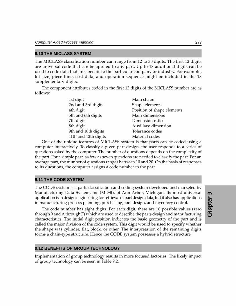
Ch
ap
ter
9C
ha
pte
r 9
Ch
ap
ter
9C
ha
pte
r 9
Ch
ap
ter
9
277Computer Aided Process Planning
9.10 THE MICLASS SYSTEM
The MICLASS classification number can range from 12 to 30 digits. The first 12 digitsare universal code that can be applied to any part. Up to 18 additional digits can beused to code data that are specific to the particular company or industry. For example,lot size, piece time, cost data, and operation sequence might be included in the 18supplementary digits.
The component attributes coded in the first 12 digits of the MICLASS number are asfollows:
1st digit Main shape2nd and 3rd digits Shape elements4th digit Position of shape elements5th and 6th digits Main dimensions7th digit Dimension ratio8th digit Auxiliary dimension9th and 10th digits Tolerance codes11th and 12th digits Material codes
One of the unique features of MICLASS system is that parts can be coded using acomputer interactively. To classify a given part design, the user responds to a series ofquestions asked by the computer. The number of questions depends on the complexity ofthe part. For a simple part, as few as seven questions are needed to classify the part. For anaverage part, the number of questions ranges between 10 and 20. On the basis of responsesto its questions, the computer assigns a code number to the part.
9.11 THE CODE SYSTEM
The CODE system is a parts classification and coding system developed and marketed byManufacturing Data System, Inc (MDSI), of Ann Arbor, Michigan. Its most universalapplication is in design engineering for retrieval of part design data, but it also has applicationsin manufacturing process planning, purchasing, tool design, and inventory control.
The code number has eight digits. For each digit, there are 16 possible values (zerothrough 9 and A through F) which are used to describe the parts design and manufacturingcharacteristics. The initial digit position indicates the basic geometry of the part and iscalled the major division of the code system. This digit would be used to specify whetherthe shape was cylinder, flat, block, or other. The interpretation of the remaining digitsforms a chain-type structure. Hence the CODE system possesses a hybrid structure.
9.12 BENEFITS OF GROUP TECHNOLOGY
Implementation of group technology results in more focused factories. The likely impactof group technology can be seen in Table 9.2.
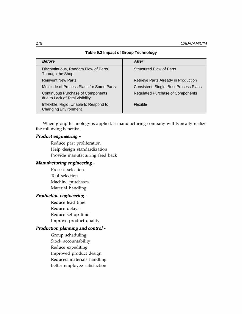
278 CAD/CAM/CIM
Table 9.2 Impact of Group Technology
Before After
Discontinuous, Random Flow of Parts Structured Flow of PartsThrough the Shop
Reinvent New Parts Retrieve Parts Already in Production
Multitude of Process Plans for Some Parts Consistent, Single, Best Process Plans
Continuous Purchase of Components Regulated Purchase of Componentsdue to Lack of Total Visibility
Inflexible, Rigid, Unable to Respond to FlexibleChanging Environment
When group technology is applied, a manufacturing company will typically realizethe following benefits:
PrPrPrPrProduct engineering -oduct engineering -oduct engineering -oduct engineering -oduct engineering -
Reduce part proliferationHelp design standardizationProvide manufacturing feed back
Manufacturing engineering -Manufacturing engineering -Manufacturing engineering -Manufacturing engineering -Manufacturing engineering -
Process selectionTool selectionMachine purchasesMaterial handling
PrPrPrPrProduction engineering -oduction engineering -oduction engineering -oduction engineering -oduction engineering -
Reduce lead timeReduce delaysReduce set-up timeImprove product quality
PrPrPrPrProduction planning and controduction planning and controduction planning and controduction planning and controduction planning and control -ol -ol -ol -ol -
Group schedulingStock accountabilityReduce expeditingImproved product designReduced materials handlingBetter employee satisfaction
Ch
ap
ter
9C
ha
pte
r 9
Ch
ap
ter
9C
ha
pte
r 9
Ch
ap
ter
9
279Computer Aided Process Planning
Other benefits:Other benefits:Other benefits:Other benefits:Other benefits:• Increased productivity• Improved accuracy in estimation of costs• Greater standardization and variety reduction• Reduced set up times• Better product delivery (Helps to implement just-in-time (JIT) manufacturing)• Reduced cost of purchasing• Improved plant efficiency
9.13 PROCESS SELECTION
Selecting the manufacturing processes to transform the raw material into the finished partis based on matching requirements with process capabilities. Process capability is the database of knowledge for each process. It includes:
i. The shape and size of part a process can produceii. The dimensions and geometric tolerances that can be obtained
iii. The surface finish attainableiv. The material removal ratev. The relative cost
vi. Technological parametersProcess engineering does not necessarily imply that all process selection is based on
the information above. However, the more the information considered in selecting a process,the more complete the result will be. A computer aided process planning system functionsbased on this process capability information.
Earlier it was mentioned that planning systems could be classified into variant andgenerative types. A variant planning system is a retrieval system and is analogous to planningbased on experience. In the variant planning system, standard plans are stored based oncomponent shape. These plans are then retrieved based on the similarity of a coded part. Agenerative system, however, makes processing, tooling and other decision via software logic.
9.14 EXPERIENCE-BASED PLANNING
It is always true that the accumulation of experience is knowledge. This is also true in thecontext of manufacturing process. Even now, many process planning activities still rely onthe experience of the process planners. However, there are some problems associated withsuch a planning approach.
i. Experience is gathered over a period of time.ii. Experience may not represent correct and current knowledge.
iii. No experience will be available in the case of new processes.
280 CAD/CAM/CIM
Because of the problems noted above, it is necessary to seek more efficient ways torepresent process capability knowledge base so that it might be preserved and installed aspart of a decision support system on a computer.
9.15 HAND BOOKS/DATA BOOKS/MANUALS
One way to store the process information is to print it in a hand book or manual. Thishas been a standard practice. Process information is usually presented in tables, figuresor listed as guide lines. Many manufacturers usually prepare their own manuals forinternal use. Some process information is listed as guide lines, so that the process plannerscan follow some general rules. For example, the following guidelines can be applied toproduce holes.
Diameter <= 8 mmDiameter <= 8 mmDiameter <= 8 mmDiameter <= 8 mmDiameter <= 8 mm TTTTTrrrrrue position > 0.01ue position > 0.01ue position > 0.01ue position > 0.01ue position > 0.01i. Tolerance > H10 Drill the hole.
ii. Tolerance <= H8 Drill and Ream etc.
9.16 DECISION TABLES AND DECISION TREES
Decision tables and decision trees are methods of describing or specifying the variousactions (decisions) associated with combination of (input) conditions. Both methods havebeen used for a long time to help decision making. This is also suitable for use withdigital computers.
9.17 PROCESS CAPABILITY
The process capability depends on the following factors:
i. Shape that a process can generate.ii. Size limitation (boundaries of the tooling, machine tooling, and fixtures).
iii. Tolerances (both dimensional and geometric).iv. Surface finish attainable.v. Cutting force.
vi. Power consumption.
The shape element implies the basic geometry predicable by a process. However, this isdifficult task to achieve using a computer that is reasoning the shape capabilities in its naturalform (geometry and topology). A feasible alternative is to represent shape by a code. Forinternal machining process, the size capability is constrained by the available tool size. Inexternal machining, size is constrained by the available machine table size. The othercapabilities and limitations can be expressed mathematically. These expressions are straightforward to programme on a computer if the exact equations and constraints can be quantified.
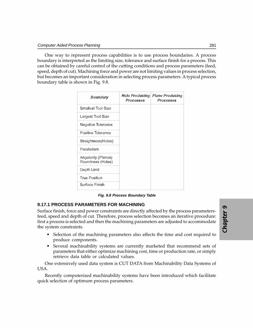
Ch
ap
ter
9C
ha
pte
r 9
Ch
ap
ter
9C
ha
pte
r 9
Ch
ap
ter
9
281Computer Aided Process Planning
One way to represent process capabilities is to use process boundaries. A processboundary is interpreted as the limiting size, tolerance and surface finish for a process. Thiscan be obtained by careful control of the cutting conditions and process parameters (feed,speed, depth of cut). Machining force and power are not limiting values in process selection,but becomes an important consideration in selecting process parameters. A typical processboundary table is shown in Fig. 9.8.
Fig. 9.8 Process Boundary Table
9.17.1 PROCESS PARAMETERS FOR MACHININGSurface finish, force and power constraints are directly affected by the process parameters-feed, speed and depth of cut. Therefore, process selection becomes an iterative procedure:first a process is selected and then the machining parameters are adjusted to accommodatethe system constraints.
• Selection of the machining parameters also affects the time and cost required toproduce components.
• Several machinability systems are currently marketed that recommend sets ofparameters that either optimize machining cost, time or production rate, or simplyretrieve data table or calculated values.
One extensively used data system is CUT DATA from Machinability Data Systems ofUSA.
Recently computerized machinability systems have been introduced which facilitatequick selection of optimum process parameters.
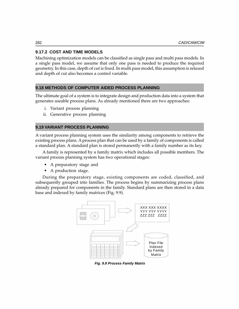
282 CAD/CAM/CIM
9.17.2 COST AND TIME MODELSMachining optimization models can be classified as single pass and multi pass models. Ina single pass model, we assume that only one pass is needed to produce the requiredgeometry. In this case, depth of cut is fixed. In multi pass model, this assumption is relaxedand depth of cut also becomes a control variable.
9.18 METHODS OF COMPUTER AIDED PROCESS PLANNING
The ultimate goal of a system is to integrate design and production data into a system thatgenerates useable process plans. As already mentioned there are two approaches:
i. Variant process planningii. Generative process planning
9.19 VARIANT PROCESS PLANNING
A variant process planning system uses the similarity among components to retrieve theexisting process plans. A process plan that can be used by a family of components is calleda standard plan. A standard plan is stored permanently with a family number as its key.
A family is represented by a family matrix which includes all possible members. Thevariant process planning system has two operational stages:
• A preparatory stage and• A production stage.
During the preparatory stage, existing components are coded, classified, andsubsequently grouped into families. The process begins by summarizing process plansalready prepared for components in the family. Standard plans are then stored in a database and indexed by family matrices (Fig. 9.9).
Matrixby FamilyIndexedPlan File
ZZZ ZZZ ZZZZYYY YYY YYYYXXX XXX XXXX
Fig. 9.9 Process Family Matrix
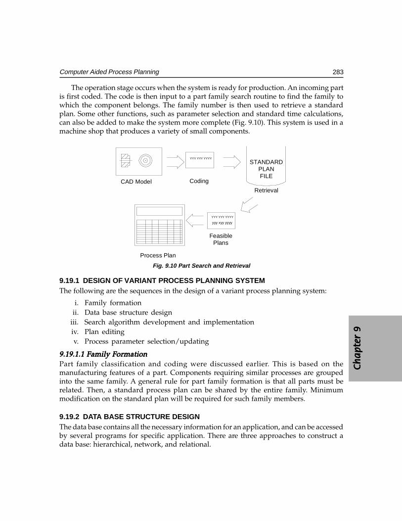
Ch
ap
ter
9C
ha
pte
r 9
Ch
ap
ter
9C
ha
pte
r 9
Ch
ap
ter
9
283Computer Aided Process Planning
The operation stage occurs when the system is ready for production. An incoming partis first coded. The code is then input to a part family search routine to find the family towhich the component belongs. The family number is then used to retrieve a standardplan. Some other functions, such as parameter selection and standard time calculations,can also be added to make the system more complete (Fig. 9.10). This system is used in amachine shop that produces a variety of small components.
PlansFeasible
Process Plan
Retrieval
CodingCAD Model
yyy xyy yyyy
YYY YYY YYYY
FILEPLAN
STANDARDYYY YYY YYYY
Fig. 9.10 Part Search and Retrieval
9.19.1 DESIGN OF VARIANT PROCESS PLANNING SYSTEMThe following are the sequences in the design of a variant process planning system:
i. Family formationii. Data base structure design
iii. Search algorithm development and implementationiv. Plan editingv. Process parameter selection/updating
9.19.1.1 Family Formation9.19.1.1 Family Formation9.19.1.1 Family Formation9.19.1.1 Family Formation9.19.1.1 Family FormationPart family classification and coding were discussed earlier. This is based on themanufacturing features of a part. Components requiring similar processes are groupedinto the same family. A general rule for part family formation is that all parts must berelated. Then, a standard process plan can be shared by the entire family. Minimummodification on the standard plan will be required for such family members.
9.19.2 DATA BASE STRUCTURE DESIGNThe data base contains all the necessary information for an application, and can be accessedby several programs for specific application. There are three approaches to construct adata base: hierarchical, network, and relational.
284 CAD/CAM/CIM
9.19.3 SEARCH PROCEDUREThe principle of a variant system is to retrieve process plans for similar components. Thesearch for a process plan is based on the search of a part family to which the componentbelongs. When, the part family is found, the associated standard plan can then be retrieved.A family matrix search can be seen as the matching of the family with a given code. Familymatrices can be considered as masks. Whenever, a code can pass through a masksuccessfully, the family is identified.
9.19.4 PLAN EDITING AND PARAMETER SELECTIONBefore a process plan can be issued to the shop, some modification of the standard planmay be necessary, and process parameters must be added to the plan. There are twotypes of plan editing: One is the editing of the standard plan itself in the data base, andthe other is editing of the plan for the component. For editing a standard plan, thestructure of the data base must be flexible enough for expansion, additions, and deletionsof the data records.
A complete process plan includes not only operations but also process parameters.The data in the process parameter files are linked so that we can go through the tree to findthe speed and feed for an operation. The parameter file can be integrated into variantplanning to select process parameters automatically.
9.20 GENERATIVE PROCESS PLANNING
Generative process planning is a system that synthesizes process information in orderto create a process plan for a new component automatically. In a generative planningsystem, process plans are created from information available in manufacturing data basewithout human intervention. Upon receiving the design model, the system can generatethe required operations and operation sequences for the component. Knowledge ofmanufacturing must be captured and encoded into efficient software. By applyingdecision logic, a process planner’s decision making can be imitated. Other planningfunctions, such as machine selection, tool selection, process optimization, and so on, canalso be automated using generative planning techniques. The generative planning hasthe following advantages:
i. It can generate consistent process plans rapidly.ii. New process plans can be created as easily as retrieving the plans of existing
components.iii. It can be interfaced with an automated manufacturing facility to provide detailed
and up-to-date control information.
Fig. 9.11 shows the modular structure of a generative CAPP system.
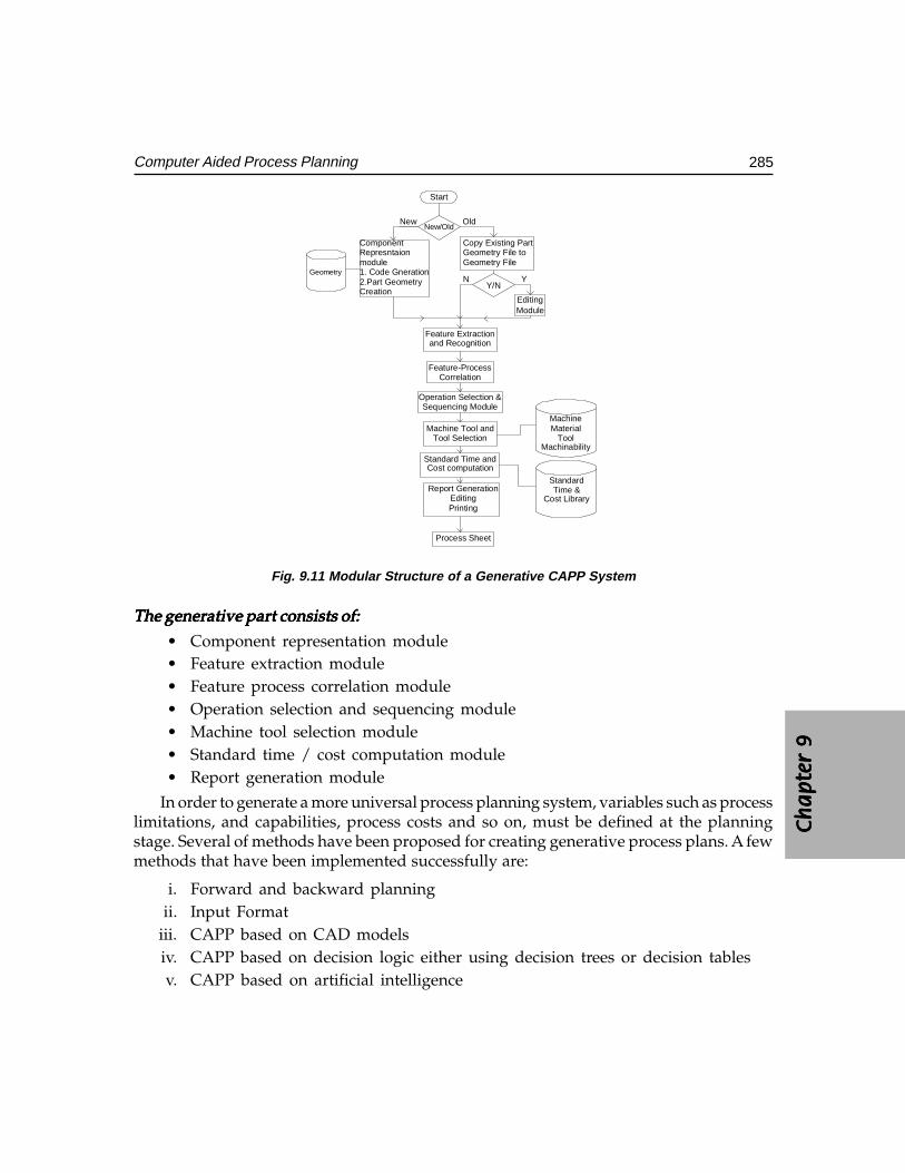
Ch
ap
ter
9C
ha
pte
r 9
Ch
ap
ter
9C
ha
pte
r 9
Ch
ap
ter
9
285Computer Aided Process Planning
Cost LibraryTime &
Standard
MachinabilityTool
MaterialMachine
Process Sheet
PrintingEditing
Report Generation
Cost computationStandard Time and
Tool SelectionMachine Tool and
Sequencing ModuleOperation Selection &
CorrelationFeature-Process
and RecognitionFeature Extraction
YN
ModuleEditing
Y/N
Geometry FileGeometry File toCopy Existing Part
Creation2.Part Geometry1. Code GnerationmoduleRepresntaion Component
Geometry
New OldNew/Old
Start
Fig. 9.11 Modular Structure of a Generative CAPP System
The generative part consists of:The generative part consists of:The generative part consists of:The generative part consists of:The generative part consists of:
• Component representation module• Feature extraction module• Feature process correlation module• Operation selection and sequencing module• Machine tool selection module• Standard time / cost computation module• Report generation module
In order to generate a more universal process planning system, variables such as processlimitations, and capabilities, process costs and so on, must be defined at the planningstage. Several of methods have been proposed for creating generative process plans. A fewmethods that have been implemented successfully are:
i. Forward and backward planningii. Input Format
iii. CAPP based on CAD models iv. CAPP based on decision logic either using decision trees or decision tables v. CAPP based on artificial intelligence
286 CAD/CAM/CIM
9.20.1 FORWARD AND BACKWARD PLANNINGIn generative process planning, when process plans are generated, the system must definean initial state in order to reach the final state (goal). The path taken represents the sequenceof processes. For example, the initial state is the raw material and the final state is thecomponent design. Then a planner works in modifying the raw workpiece until it takeson the final design qualities. This is called forward planning.
Backward planning uses a reverse procedure. Assuming that we have a finishedcomponent, the goal is to go back to the un-machined workpiece. Each machining processis considered a filling process.
Forward and backward planning may seem similar. However they influence theprogramming of the system significantly. Planning each process can be characterized by aprecondition of the surface to be machined and a post condition of the machining (the endresult). For forward planning, we must know the successor surface before we select aprocess, because the post condition of the first process becomes the precondition for secondprocess. Backward planning eliminates this problem since it begins with the final surfacesfrom and processes are selected to satisfy the initial requirements.
In forward planning, the steps to obtain the final surface with the desirable attributesmust be carefully planned to guarantee the result. On the other hand, backward planningstarts with the final requirements and searches for the initial condition.
9.20.2 INPUT FORMATThe input format of a process planning system affects the ease with which a system can beused, and the capability of the system. The transitional form from the original design(either engineering drawing or CAD model) to a specific input format may be tedious anddifficult to automate. However, such input can provide more complete information abouta component, and more planning functions can be accomplished using the input.
Many different input formats have been used in process planning systems. Some ofthe few input formats used are:
CODE:CODE:CODE:CODE:CODE: Some generative systems such as APPAS use GT codes as input. Codes usedare in generative system are more detailed.
DESCRIPTION LANGUAGE:DESCRIPTION LANGUAGE:DESCRIPTION LANGUAGE:DESCRIPTION LANGUAGE:DESCRIPTION LANGUAGE: Specially designed part description languages canprovide detailed information for process planning system. For example AUTAP systemuses a language similar to a solid modeling language. A component is described by theunion of some primitives and modifiers. Material, processes, machine selection, and timeestimates can be selected by the system using the input model. Another system CIMS/PRO uses an input language called CIMS/DEC. CAPP system uses its own special language.
9.20.3 CAPP BASED ON CAD MODELSUsing a CAD model as input to a process planning system can eliminate the human
effort of translating a design into code and other descriptive form. A CAD model contains
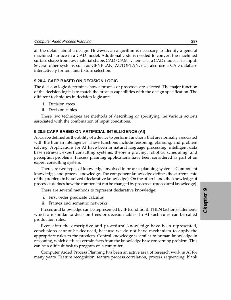
Ch
ap
ter
9C
ha
pte
r 9
Ch
ap
ter
9C
ha
pte
r 9
Ch
ap
ter
9
287Computer Aided Process Planning
all the details about a design. However, an algorithm is necessary to identify a generalmachined surface in a CAD model. Additional code is needed to convert the machinedsurface shape from raw material shape. CAD/CAM system uses a CAD model as its input.Several other systems such as GENPLAN, AUTOPLAN, etc., also use a CAD databaseinteractively for tool and fixture selection.
9.20.4 CAPP BASED ON DECISION LOGICThe decision logic determines how a process or processes are selected. The major functionof the decision logic is to match the process capabilities with the design specification. Thedifferent techniques in decision logic are:
i. Decision treesii. Decision tables
These two techniques are methods of describing or specifying the various actionsassociated with the combination of input conditions.
9.20.5 CAPP BASED ON ARTIFICIAL INTELLIGENCE (AI)AI can be defined as the ability of a device to perform functions that are normally associatedwith the human intelligence. These functions include reasoning, planning, and problemsolving. Applications for AI have been in natural language processing, intelligent database retrieval, expert consulting systems, theorem proving, robotics, scheduling, andperception problems. Process planning applications have been considered as part of anexpert consulting system.
There are two types of knowledge involved in process planning systems: Componentknowledge, and process knowledge. The component knowledge defines the current stateof the problem to be solved (declarative knowledge). On the other hand, the knowledge ofprocesses defines how the component can be changed by processes (procedural knowledge).
There are several methods to represent declarative knowledge:
i. First order predicate calculusii. Frames and semantic networks
Procedural knowledge can be represented by IF (condition), THEN (action) statementswhich are similar to decision trees or decision tables. In AI such rules can be calledproduction rules.
Even after the descriptive and procedural knowledge have been represented,conclusions cannot be deduced, because we do not have mechanism to apply theappropriate rules to the problem. Control knowledge is similar to human knowledge inreasoning, which deduces certain facts from the knowledge base concerning problem. Thiscan be a difficult task to program on a computer.
Computer Aided Process Planning has been an active area of research work in AI formany years. Feature recognition, feature process correlation, process sequencing, blank
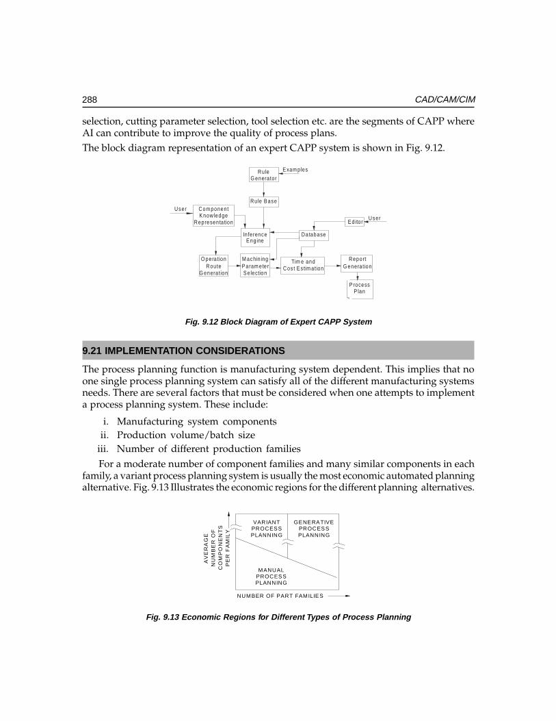
288 CAD/CAM/CIM
selection, cutting parameter selection, tool selection etc. are the segments of CAPP whereAI can contribute to improve the quality of process plans.The block diagram representation of an expert CAPP system is shown in Fig. 9.12.
U ser
E xam ples
P lanP rocess
G enera tionR eport
C os t E s tim a tionTim e and
S e lectionP aram ete rM achin ing
G enera tionR oute
O pera tion
U serE d ito r
D a tabaseE ng ine
In fe rence
R epresen ta tionK now ledgeC om ponen t
R u le B ase
G enera to rR u le
Fig. 9.12 Block Diagram of Expert CAPP System
9.21 IMPLEMENTATION CONSIDERATIONS
The process planning function is manufacturing system dependent. This implies that noone single process planning system can satisfy all of the different manufacturing systemsneeds. There are several factors that must be considered when one attempts to implementa process planning system. These include:
i. Manufacturing system componentsii. Production volume/batch size
iii. Number of different production familiesFor a moderate number of component families and many similar components in each
family, a variant process planning system is usually the most economic automated planningalternative. Fig. 9.13 Illustrates the economic regions for the different planning alternatives.
PE
R F
AM
ILY
CO
MP
ON
EN
TS
NU
MB
ER
OF
AV
ER
AG
E
NUMBER OF PART FAMILIES
PLANNINGPROCESSMANUAL
PLANNINGPROCESS
GENERATIVE
PLANNINGPROCESSVARIANT
Fig. 9.13 Economic Regions for Different Types of Process Planning
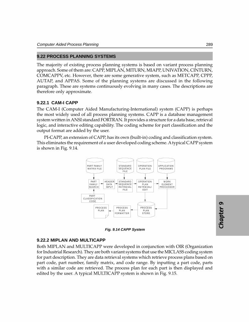
Ch
ap
ter
9C
ha
pte
r 9
Ch
ap
ter
9C
ha
pte
r 9
Ch
ap
ter
9
289Computer Aided Process Planning
9.22 PROCESS PLANNING SYSTEMS
The majority of existing process planning systems is based on variant process planningapproach. Some of them are: CAPP, MIPLAN, MITURN, MIAPP, UNIVATION, CINTURN,COMCAPPV, etc. However, there are some generative system, such as METCAPP, CPPP,AUTAP, and APPAS. Some of the planning systems are discussed in the followingparagraph. These are systems continuously evolving in many cases. The descriptions aretherefore only approximate.
9.22.1 CAM-I CAPPThe CAM-I (Computer Aided Manufacturing-International) system (CAPP) is perhapsthe most widely used of all process planning systems. CAPP is a database managementsystem written in ANSI standard FORTRAN. It provides a structure for a data base, retrievallogic, and interactive editing capability. The coding scheme for part classification and theoutput format are added by the user.
PI-CAPP, an extension of CAPP, has its own (built-in) coding and classification system.This eliminates the requirement of a user developed coding scheme. A typical CAPP systemis shown in Fig. 9.14.
CO DECL ASSIF ICAT IO N
PART
PLANPRO CESS
FOR M ATTERPLAN
PRO CESS
STO REPLAN
PRO CESS
PRO CESSO RELEM EN T
W OR K
EDITRETRIEVAL/
PLANO PERAT IO N
F IL ERETRIEVALSEQ UENCESTANDAR D
INPUTDATA
HEAD ER
SEARC HFAM ILY
PART
PRO G RAM SAPPLICAT ION
PLAN F ILEO PERAT IO N
F IL ESEQ UENCESTANDAR D
M ATRIX F ILEPART FAM ILY
Fig. 9.14 CAPP System
9.22.2 MIPLAN AND MULTICAPPBoth MIPLAN and MULTICAPP were developed in conjunction with OIR (Organizationfor Industrial Research). They are both variant systems that use the MICLASS coding systemfor part description. They are data retrieval systems which retrieve process plans based onpart code, part number, family matrix, and code range. By inputting a part code, partswith a similar code are retrieved. The process plan for each part is then displayed andedited by the user. A typical MULTICAPP system is shown in Fig. 9.15.
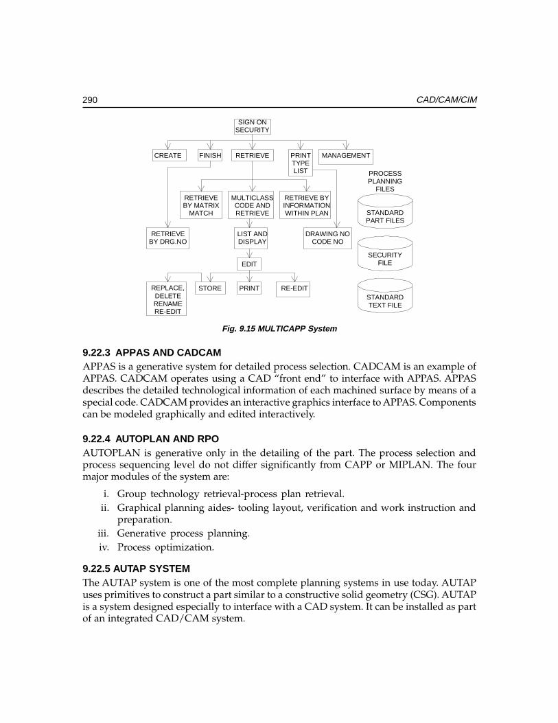
290 CAD/CAM/CIM
FILESPLANNINGPROCESS
STANDARD
TEXT FILESTANDARD
FILESECURITY
PART FILES
RE-EDITRENAMEDELETE
REPLACE, STORE RE-EDITPRINT
EDIT
CODE NODRAWING NO
DISPLAYLIST AND
BY DRG.NORETRIEVE
WITHIN PLANINFORMATIONRETRIEVE BY
RETRIEVECODE AND
MULTICLASS
MATCHBY MATRIXRETRIEVE
MANAGEMENT
LISTTYPEPRINTRETRIEVEFINISHCREATE
SECURITYSIGN ON
Fig. 9.15 MULTICAPP System
9.22.3 APPAS AND CADCAMAPPAS is a generative system for detailed process selection. CADCAM is an example ofAPPAS. CADCAM operates using a CAD “front end” to interface with APPAS. APPASdescribes the detailed technological information of each machined surface by means of aspecial code. CADCAM provides an interactive graphics interface to APPAS. Componentscan be modeled graphically and edited interactively.
9.22.4 AUTOPLAN AND RPOAUTOPLAN is generative only in the detailing of the part. The process selection andprocess sequencing level do not differ significantly from CAPP or MIPLAN. The fourmajor modules of the system are:
i. Group technology retrieval-process plan retrieval.ii. Graphical planning aides- tooling layout, verification and work instruction and
preparation.iii. Generative process planning.iv. Process optimization.
9.22.5 AUTAP SYSTEMThe AUTAP system is one of the most complete planning systems in use today. AUTAPuses primitives to construct a part similar to a constructive solid geometry (CSG). AUTAPis a system designed especially to interface with a CAD system. It can be installed as partof an integrated CAD/CAM system.
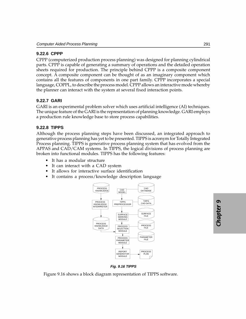
Ch
ap
ter
9C
ha
pte
r 9
Ch
ap
ter
9C
ha
pte
r 9
Ch
ap
ter
9
291Computer Aided Process Planning
9.22.6 CPPPCPPP (computerized production process planning) was designed for planning cylindricalparts. CPPP is capable of generating a summary of operations and the detailed operationsheets required for production. The principle behind CPPP is a composite componentconcept. A composite component can be thought of as an imaginary component whichcontains all the features of components in one part family. CPPP incorporates a speciallanguage, COPPL, to describe the process model. CPPP allows an interactive mode wherebythe planner can interact with the system at several fixed interaction points.
9.22.7 GARIGARI is an experimental problem solver which uses artificial intelligence (AI) techniques.The unique feature of the GARI is the representation of planning knowledge. GARI employsa production rule knowledge base to store process capabilities.
9.22.8 TIPPSAlthough the process planning steps have been discussed, an integrated approach togenerative process planning has yet to be presented. TIPPS is acronym for Totally IntegratedProcess planning. TIPPS is generative process planning system that has evolved from theAPPAS and CAD/CAM systems. In TIPPS, the logical divisions of process planning arebroken into functional modules. TIPPS has the following features:
• It has a modular structure• It can interact with a CAD system• It allows for interactive surface identification• It contains a process/knowledge description language
PLANPROCESS
MODULEGENERATOR
REPORT
DATAKNOWLEDGE
PROCESS
INTERPRETERKNOWLEDGE
PROCESS
KNOWLEDGEPROCESS
MODULEPARAMETER
PROCESS
MODULESELECTIONPROCESS
MODULEMARKINGSURFACE
PREPROCESSORTIPPS
MODELCAD
FILEPARAMETER
FILEPROCESS
FILESURFACE
CAD DATATIPPS
DATABASECAD
Fig. 9.16 TIPPS
Figure 9.16 shows a block diagram representation of TIPPS software.
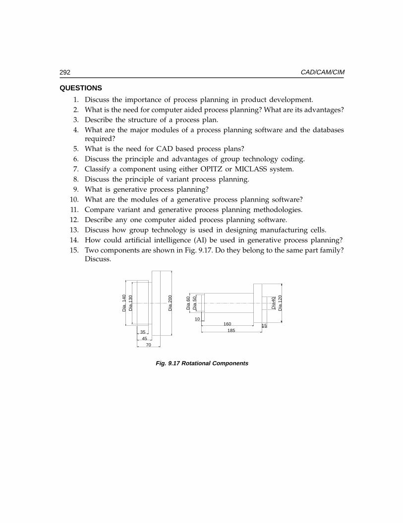
292 CAD/CAM/CIM
QUESTIONS
1. Discuss the importance of process planning in product development.2. What is the need for computer aided process planning? What are its advantages?3. Describe the structure of a process plan.4. What are the major modules of a process planning software and the databases
required?5. What is the need for CAD based process plans?6. Discuss the principle and advantages of group technology coding.7. Classify a component using either OPITZ or MICLASS system.8. Discuss the principle of variant process planning.9. What is generative process planning?
10. What are the modules of a generative process planning software?11. Compare variant and generative process planning methodologies.12. Describe any one computer aided process planning software.13. Discuss how group technology is used in designing manufacturing cells.14. How could artificial intelligence (AI) be used in generative process planning?15. Two components are shown in Fig. 9.17. Do they belong to the same part family?
Discuss.
15185
16010
Dia
40
Dia
60
Dia
50
Dia
.130
7045
35
Dia
.200
Dia
. 140
Dia
.120
Fig. 9.17 Rotational Components
���������������� ���
����� ��� ���
��� ������������
�������
������
Information systems are used to organize and manage the manufacturing environment,and to deliver manufacturing information in a useful and timely fashion to various sub-systems of manufacturing to create dynamic enterprises. An efficient enterprise resourcesplanning system will help to increase the productivity in manufacturing and improve profitsand market share applications. There are a number of manufacturing planning systempackages and enterprise resource planning systems available today for a wide range ofmicro, mini and main frame installations from various vendors. This chapter deals with thesegments of manufacturing resource planning and introduces ERP, dynamic enterprisemodeling and supply chain management.
10.1 INTRODUCTION
Manufacturing companies, large and small, continually seek to improve response tocustomers, increase profitability and become more competitive. Their aim is to make savingsin working capital by reducing stocks, service and support costs whilst improving cycletimes, deliveries and quality. Advanced computer based management planning and controlsystems help to achieve these aims.
In recent years due to the pressure of globalization, the highly competitive world ofmanufacturing has grown increasingly complex. As new methods for production andinventory control have arisen and demands for increased productivity have mounted,proper manufacturing planning and control of manufacturing resources have becomeessential. The concept of manufacturing planning has been enlarged to include the entireenterprise covering such critical issues like logistics and supply chain management. Infact, efficiency of information management and proper manufacturing planning createstrategic advantages that can translate into increased market share and improved profitmargins. The need for proper planning and execution of manufacturing plans has resulted
294 CAD/CAM/CIM
in the development of IT based systems to organize and manage the manufacturing toall users concerned.
10.2 BACKGROUND
In the 1960’s with the population of computers and their popularity growing,manufacturers looked for ways to use them to facilitate ordering of materials and partsfor their manufacturing goods. This resulted in the development of software called MRP(Material Requirement Planning). MRP was a simple computer program for planningmaterial orders with the purpose of reducing inventory, responding more effectively tomarket demand, and ultimately increasing sales.
MRP is a time-phased planning system that detects when the due date of an order isout of phase with it’s “need date”, and ultimately keeps the priorities valid in a changingmanufacturing environment. The original MRP programs linked material requirementswith inventory levels and replenishment purchase orders and work orders over a timeframe. MRP brought out discrepancies and helped to restore a balance between theinventory requirements and replenishments. The program determined net requirementsfor every manufactured and purchased component and created planned purchase ordersor work orders for these items.
The managers were then required to either confirm the orders or change the quantitiesor due dates. MRP was a very good management planning tool, if the indicatedmanufacturing lead time and the inventory levels were correct. Despite this method, whichimproved inventory control and material planning, many manufacturers realized therewere several segments in the manufacturing chain that were missing. They constantly feltthat there was more to their job than monitoring material availability.
This led to the development of manufacturing resource planning or MRP II. MRP-IIsystems go for beyond the planning tools of MRP. They are in effect manufacturing controlsystems. These systems can plan, track, and control almost any aspect of manufacturing,from inventory levels to job costing, to the placement of finished goods on the proper truckto get to the right distributor. However, as the compulsions of the global competition andcomplexities of economic manufacturing grew the manufacturers had to go for more efficientplanning tools. This led to the development of enterprise resource planning (ERP). ERPattempts a dynamic enterprise modeling which can respond to any exigencies of amanufacturing and marketing demand. Further, manufacturers are implementing efficientsupply chain management systems to keep customers happy and maintain their profit levels.Information Technology (IT) has thus become the back bone of manufacturing activity.
A word of caution may not be out of place here. Any manufacturing system will notgive the desired results unless the focus is on continuous improvement. Traditionally,systems have been designed “top down.” In simple terms, the approach has been one ofimitating the “push system”. This is in contrast with the Toyota Production System (TPS)
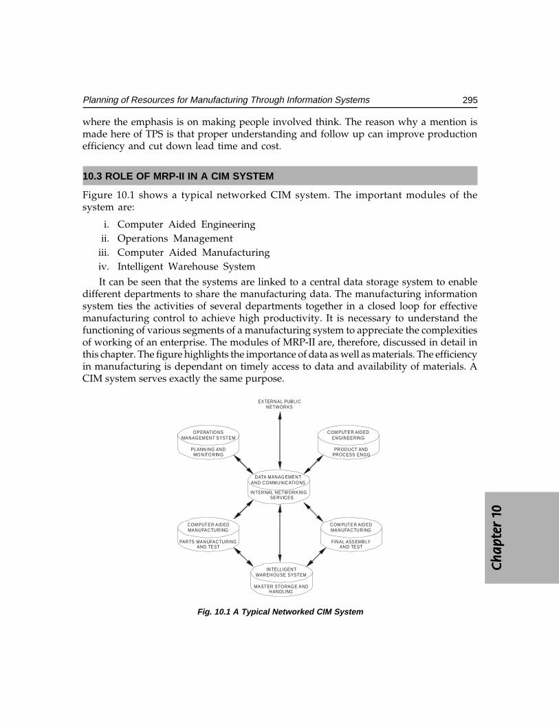
Ch
ap
ter
1C
ha
pte
r 1
Ch
ap
ter
1C
ha
pte
r 1
Ch
ap
ter
1 0000 0
295Planning of Resources for Manufacturing Through Information Systems
where the emphasis is on making people involved think. The reason why a mention ismade here of TPS is that proper understanding and follow up can improve productionefficiency and cut down lead time and cost.
10.3 ROLE OF MRP-II IN A CIM SYSTEM
Figure 10.1 shows a typical networked CIM system. The important modules of thesystem are:
i. Computer Aided Engineeringii. Operations Management
iii. Computer Aided Manufacturingiv. Intelligent Warehouse System
It can be seen that the systems are linked to a central data storage system to enabledifferent departments to share the manufacturing data. The manufacturing informationsystem ties the activities of several departments together in a closed loop for effectivemanufacturing control to achieve high productivity. It is necessary to understand thefunctioning of various segments of a manufacturing system to appreciate the complexitiesof working of an enterprise. The modules of MRP-II are, therefore, discussed in detail inthis chapter. The figure highlights the importance of data as well as materials. The efficiencyin manufacturing is dependant on timely access to data and availability of materials. ACIM system serves exactly the same purpose.
DATA MANAG EMENTAND COMMUNICATIONS
COM PUTER AIDEDENGINEERING
PRODUCT ANDPROCESS ENGG
OPERATIONSMANAGEMENT SYSTEM
PLANNING ANDMO NITO RING
INTERNAL NETWORKINGSERVICES
COM PUTER AIDEDMANUFACTURING
PARTS MANUFACTURINGAND TEST
COM PUTER AIDEDMANUFACTURING
FINAL ASSEMBLYAND TEST
INTELLIGENTWAREHOUSE SYSTEM
MASTER STORAGE ANDHANDLING
EXTERNAL PUBLICNETWORKS
Fig. 10.1 A Typical Networked CIM System
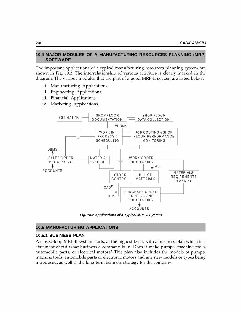
296 CAD/CAM/CIM
10.4 MAJOR MODULES OF A MANUFACTURING RESOURCES PLANNING (MRP)SOFTWARE
The important applications of a typical manufacturing resources planning system areshown in Fig. 10.2. The interrelationship of various activities is clearly marked in thediagram. The various modules that are part of a good MRP-II system are listed below:
i. Manufacturing Applicationsii. Engineering Applications
iii. Financial Applicationsiv. Marketing Applications
E S TIM AT IN GS H O P F LO O R
D O C U M EN TAT IO NS H O P F LO O R
D ATA C O LL EC T IO N
W O R K IN P R O C ES S &
S C H E D U L IN G
JO B C O S T IN G & SH O PF L O O R P ER F O R M AN C E
M O N IT O R IN G
S A L ES O R D E RP R O C ES S IN G
M ATE R IALS C H E D U L E
W O R K O R D ERP R O C ES S IN G
S TO C KC O N T R O L
B IL L O FM ATE R IAL S
M ATE R IAL SR E Q IR E M E N T S
P L A N N IN G
P U R C H A S E O R D E R P R IN T IN G AN DP R O C ES S IN G
A C C O U N T S
D B M S
C A D
C A D
D B M S
D B M S
A C C O U N T S
Fig. 10.2 Applications of a Typical MRP-II System
10.5 MANUFACTURING APPLICATIONS
10.5.1 BUSINESS PLANA closed-loop MRP-II system starts, at the highest level, with a business plan which is astatement about what business a company is in. Does it make pumps, machine tools,automobile parts, or electrical motors? This plan also includes the models of pumps,machine tools, automobile parts or electronic motors and any new models or types beingintroduced, as well as the long-term business strategy for the company.
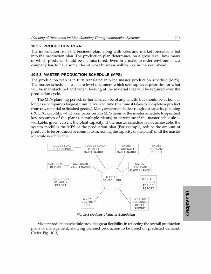
Ch
ap
ter
1C
ha
pte
r 1
Ch
ap
ter
1C
ha
pte
r 1
Ch
ap
ter
1 0000 0
297Planning of Resources for Manufacturing Through Information Systems
10.5.2 PRODUCTION PLANThe information from the business plan, along with sales and market forecasts, is fedinto the production plan. The production plan determines, on a gross level, how manyof which products should be manufactured. Even in a make-to-order environment, acompany has to have some idea of what business will be like in the year ahead.
10.5.3 MASTER PRODUCTION SCHEDULE (MPS)The production plan is in turn translated into the master production schedule (MPS).The master schedule is a macro level document which sets top-level priorities for whatwill be manufactured and when, looking at the material that will be required over theproduction cycle.
The MPS planning period, or horizon, can be of any length, but should be at least aslong as a company’s longest cumulative lead time (the time it takes to complete a productfrom raw material to finished goods.). Many systems include a rough cut capacity planning(RCCP) capability, which compares certain MPS items of the master schedule to specifiedkey resources of the plant (or multiple plants) to determine if the master schedule isworkable, given current the plant capacity. If the master schedule is not achievable, thesystem modifies the MPS or the production plan (For example, reduce the amount ofproducts to be produced or commit to increasing the capacity of the plant) until the masterschedule is achievable.
PRO DU CT LO A DPRO FILE REP O RT
PRO DU CT LO A DPRO FILE
M AINTEN ANCE
SALE S FOR ECAST
M AINTEN ANCE
SALE SFOR ECAST
REPO RT
CALEND ARREPO RT
CALEND ARM AINTEN ANCE
SALE S FOR ECAST
M AINTEN ANCE
M ASTER SCH EDULE
PERIO DREPO RT
M ASTERSCH EDULE
DETAILREPO RT
W O RKCEN TR E
LIST
RO UG H C UTCAPACITYREPO RT
M ASTERSCH EDULIN G
Fig. 10.3 Modules of Master Scheduling
Master production schedule provides great flexibility in reflecting the overall productionplans of management, allowing planned production to be based on predicted demand.(Refer Fig. 10.3)
298 CAD/CAM/CIM
The master production schedule software is useful in many ways.
• Enables the user to scan through the file starting at any point to easily locatedata.
• Accesses items by number or partial description.
• Eases forecasting.
• Allows interactive entry of requirement and replenishment orders on the masterschedule including creation of firm planned orders.
• Merges existing shop orders, purchase orders, and MRP planned orders intothe master schedule for easy comparison with customer orders and salesforecast orders.
• Maintains orders by exact date, allowing reports to be detailed or summarizesinto a variety of user-defined periods.
• Supports “what if” analysis by projecting into the future with adjustments toquantities.
• Displays or prints how much of each inventory item is available to promise fordelivery in current and future periods.
• Identifies under or over-scheduled key work centres though rough cut capacityplanning.
• Pinpoints desired information responding to user-specified parameters.
10.5.4 MATERIALS REQUIREMENTS PLANNING
The master production schedule becomes a direct input to the material requirementsplanning (MRP) function, which determines the material needed at each work centrelocation in order to meet the master production schedule. MRP is the heart of anymanufacturing control system. It uses information from the bills of material, inventory,shop and purchase orders, and the master schedule to draw a detailed material requirementsplan. MRP accesses the data from the master production to determine what products willbe built during the planning period.
Bills of material and routings define the raw materials required to produce the product,the instructions and routing(s) through the shop the shop floor for producing the product.MRP determines the total gross requirements and compares against current inventory andscheduled receipts (any replenishment orders due).
If MRP determines that material will not be available when it is required, it canregenerate planned orders for that material. Figure 10.4 illustrates the important sub-modules of MRP.
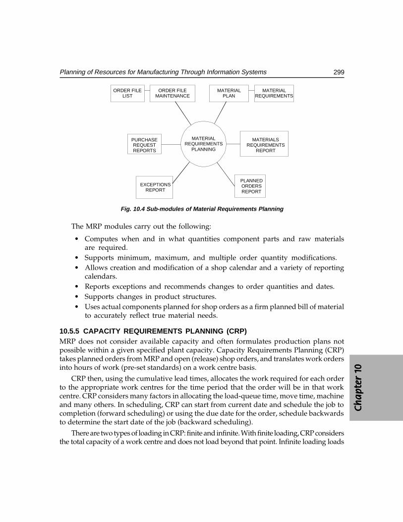
Ch
ap
ter
1C
ha
pte
r 1
Ch
ap
ter
1C
ha
pte
r 1
Ch
ap
ter
1 0000 0
299Planning of Resources for Manufacturing Through Information Systems
MATERIALREQUIREMENTS
PLANNING
ORDER FILELIST
ORDER FILEMAINTENANCE
MATERIALPLAN
MATERIALREQUIREMENTS
EXCEPTIONSREPORT
PLANNEDORDERSREPORT
MATERIALSREQUIREMENTS
REPORT
PURCHASEREQUESTREPORTS
Fig. 10.4 Sub-modules of Material Requirements Planning
The MRP modules carry out the following:
• Computes when and in what quantities component parts and raw materialsare required.
• Supports minimum, maximum, and multiple order quantity modifications.• Allows creation and modification of a shop calendar and a variety of reporting
calendars.• Reports exceptions and recommends changes to order quantities and dates.• Supports changes in product structures.• Uses actual components planned for shop orders as a firm planned bill of material
to accurately reflect true material needs.
10.5.5 CAPACITY REQUIREMENTS PLANNING (CRP)MRP does not consider available capacity and often formulates production plans notpossible within a given specified plant capacity. Capacity Requirements Planning (CRP)takes planned orders from MRP and open (release) shop orders, and translates work ordersinto hours of work (pre-set standards) on a work centre basis.
CRP then, using the cumulative lead times, allocates the work required for each orderto the appropriate work centres for the time period that the order will be in that workcentre. CRP considers many factors in allocating the load-queue time, move time, machineand many others. In scheduling, CRP can start from current date and schedule the job tocompletion (forward scheduling) or using the due date for the order, schedule backwardsto determine the start date of the job (backward scheduling).
There are two types of loading in CRP: finite and infinite. With finite loading, CRP considersthe total capacity of a work centre and does not load beyond that point. Infinite loading loads
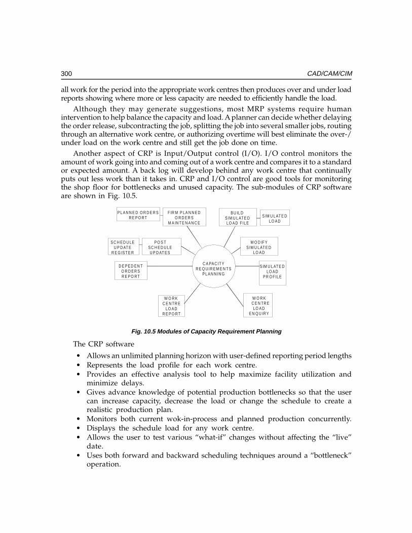
300 CAD/CAM/CIM
all work for the period into the appropriate work centres then produces over and under loadreports showing where more or less capacity are needed to efficiently handle the load.
Although they may generate suggestions, most MRP systems require humanintervention to help balance the capacity and load. A planner can decide whether delayingthe order release, subcontracting the job, splitting the job into several smaller jobs, routingthrough an alternative work centre, or authorizing overtime will best eliminate the over-/under load on the work centre and still get the job done on time.
Another aspect of CRP is Input/Output control (I/O). I/O control monitors theamount of work going into and coming out of a work centre and compares it to a standardor expected amount. A back log will develop behind any work centre that continuallyputs out less work than it takes in. CRP and I/O control are good tools for monitoringthe shop floor for bottlenecks and unused capacity. The sub-modules of CRP softwareare shown in Fig. 10.5.
C A PA C IT YR E Q U IR E M E N T S
P L A N N IN G
P L A N N E D O R D E R SR E P O R T
F IR M P LA N N E DO R D E R S
M A IN T E N A N C E
B U IL D S IM U L AT E DLO A D F ILE
S IM U L AT E DLO A D
S C H E D U LEU P D AT E
R E G IS T E R
P O S TS C H E D U LEU P D AT E S
M O D IF YS IM U L AT E D
LO A D
D E P E D E N TO R D E R SR E P O R T
W O R K C E N TR E
LO A DR E P O R T
W O R KC E N TR ELO A D
E N Q U IR Y
S IM U L AT E DLO A D
P R O F ILE
Fig. 10.5 Modules of Capacity Requirement Planning
The CRP software
• Allows an unlimited planning horizon with user-defined reporting period lengths• Represents the load profile for each work centre.• Provides an effective analysis tool to help maximize facility utilization and
minimize delays.• Gives advance knowledge of potential production bottlenecks so that the user
can increase capacity, decrease the load or change the schedule to create arealistic production plan.
• Monitors both current wok-in-process and planned production concurrently.• Displays the schedule load for any work centre.• Allows the user to test various “what-if” changes without affecting the “live”
date.• Uses both forward and backward scheduling techniques around a “bottleneck”
operation.
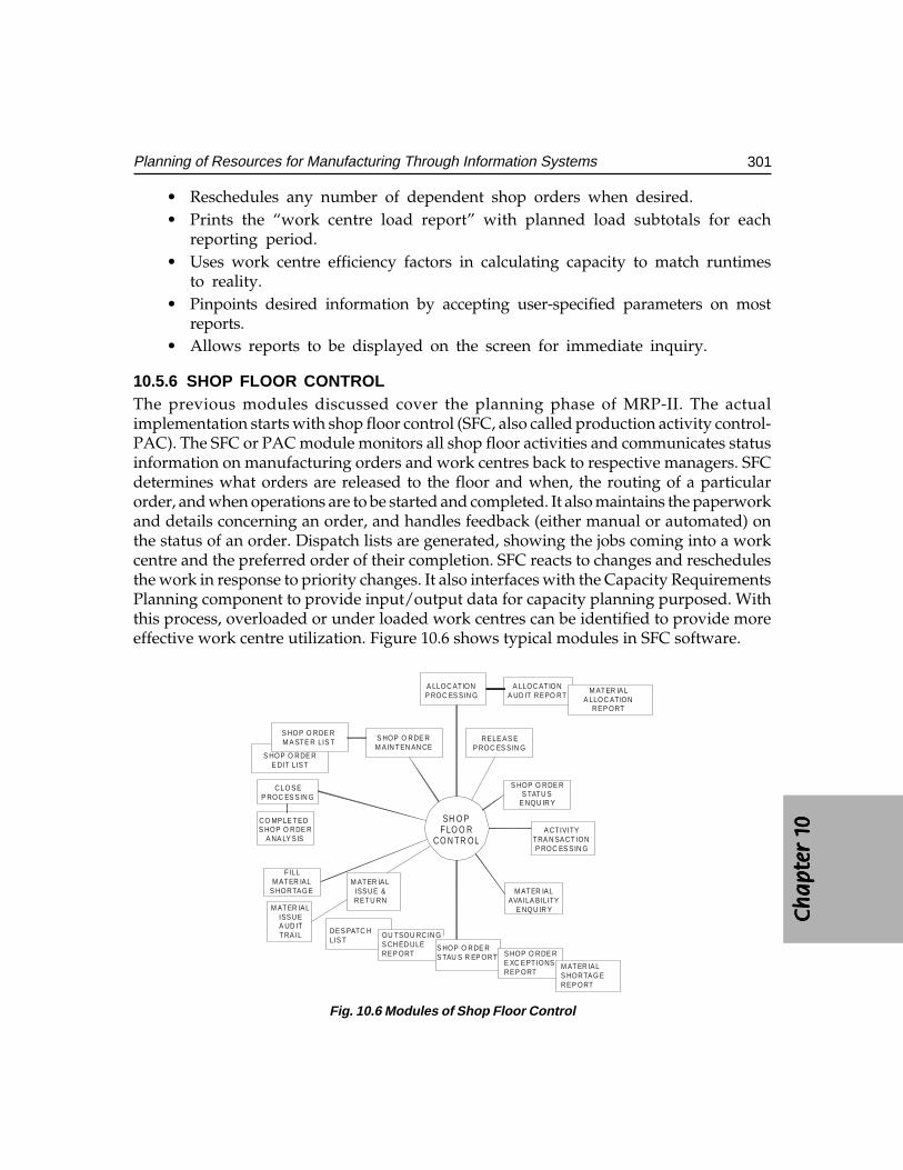
Ch
ap
ter
1C
ha
pte
r 1
Ch
ap
ter
1C
ha
pte
r 1
Ch
ap
ter
1 0000 0
301Planning of Resources for Manufacturing Through Information Systems
• Reschedules any number of dependent shop orders when desired.• Prints the “work centre load report” with planned load subtotals for each
reporting period.• Uses work centre efficiency factors in calculating capacity to match runtimes
to reality.• Pinpoints desired information by accepting user-specified parameters on most
reports.• Allows reports to be displayed on the screen for immediate inquiry.
10.5.6 SHOP FLOOR CONTROLThe previous modules discussed cover the planning phase of MRP-II. The actualimplementation starts with shop floor control (SFC, also called production activity control-PAC). The SFC or PAC module monitors all shop floor activities and communicates statusinformation on manufacturing orders and work centres back to respective managers. SFCdetermines what orders are released to the floor and when, the routing of a particularorder, and when operations are to be started and completed. It also maintains the paperworkand details concerning an order, and handles feedback (either manual or automated) onthe status of an order. Dispatch lists are generated, showing the jobs coming into a workcentre and the preferred order of their completion. SFC reacts to changes and reschedulesthe work in response to priority changes. It also interfaces with the Capacity RequirementsPlanning component to provide input/output data for capacity planning purposed. Withthis process, overloaded or under loaded work centres can be identified to provide moreeffective work centre utilization. Figure 10.6 shows typical modules in SFC software.
S HOP O RDE RM A STE R LIS T S HOP O RDE R
M A IN TEN AN CERELE AS E
P ROC ES SIN GS HOP O RDE R
E DIT LIST
CLO SEP ROC ES SIN G
CO MPLE TED S HOP O RDE R
A NA LY SIS
FILLM ATER IAL
S HORTAG E
M ATER IALISSUEA UD ITTRA IL
M ATER IALISSUE &RETU RN
S HOP O RDE RS TATU S
E NQU IR Y
A CTIVITYTRA N SACTIONP ROC ES SIN G
M ATER IALAVAILA BILITY
E NQU IR Y
DES PATC HLIS T
OU TSOU RC IN GS CH ED ULEREP ORT
S HOP O RDE RS TAU S R EP ORT S HOP O RDE R
E XC EPTIONSREP ORT
M ATER IALS HORTAG EREP ORT
A LLOC ATIONP ROC ES SIN G
A LLOC ATIONA UD IT REPO RT
M ATER IALA LLOC ATION
REP ORT
SH O PF LO O R
C O N TR OL
Fig. 10.6 Modules of Shop Floor Control
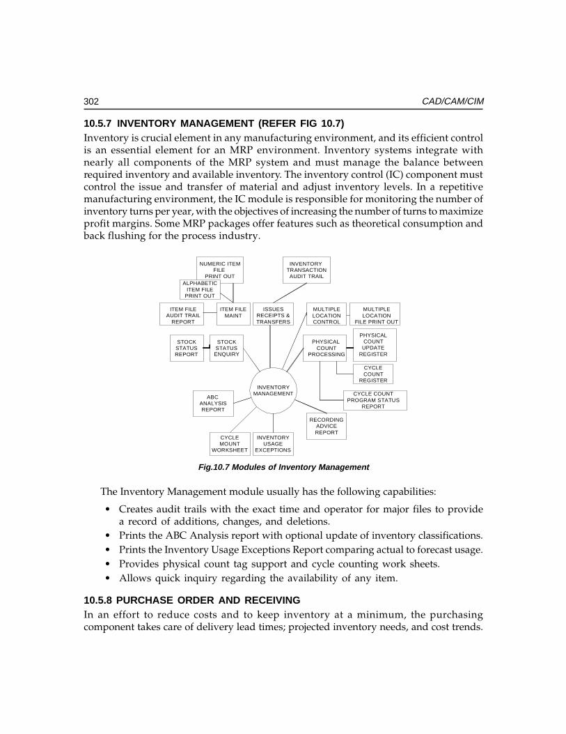
302 CAD/CAM/CIM
10.5.7 INVENTORY MANAGEMENT (REFER FIG 10.7)Inventory is crucial element in any manufacturing environment, and its efficient controlis an essential element for an MRP environment. Inventory systems integrate withnearly all components of the MRP system and must manage the balance betweenrequired inventory and available inventory. The inventory control (IC) component mustcontrol the issue and transfer of material and adjust inventory levels. In a repetitivemanufacturing environment, the IC module is responsible for monitoring the number ofinventory turns per year, with the objectives of increasing the number of turns to maximizeprofit margins. Some MRP packages offer features such as theoretical consumption andback flushing for the process industry.
NUMERIC ITEMFILE
PRINT OUTALPHABETIC
ITEM FILEPRINT OUT
INVENTORY TRANSACTIONAUDIT TRAIL
ITEM FILEAUDIT TRAIL
REPORT
ITEM FILEMAINT
ISSUESRECEIPTS &TRANSFERS
MULTIPLELOCATIONCONTROL
MULTIPLELOCATION
FILE PRINT OUT
STOCKSTATUSREPORT
STOCKSTATUS
ENQUIRY
PHYSICAL COUNT
PROCESSING
PHYSICALCOUNT
UPDATEREGISTER
CYCLECOUNT
REGISTER
CYCLE COUNTPROGRAM STATUS
REPORT
RECORDINGADVICEREPORT
INVENTORYUSAGE
EXCEPTIONS
CYCLEMOUNT
WORKSHEET
ABC ANALYSISREPORT
INVENTORYMANAGEMENT
Fig.10.7 Modules of Inventory Management
The Inventory Management module usually has the following capabilities:
• Creates audit trails with the exact time and operator for major files to providea record of additions, changes, and deletions.
• Prints the ABC Analysis report with optional update of inventory classifications.• Prints the Inventory Usage Exceptions Report comparing actual to forecast usage.• Provides physical count tag support and cycle counting work sheets.• Allows quick inquiry regarding the availability of any item.
10.5.8 PURCHASE ORDER AND RECEIVINGIn an effort to reduce costs and to keep inventory at a minimum, the purchasingcomponent takes care of delivery lead times; projected inventory needs, and cost trends.
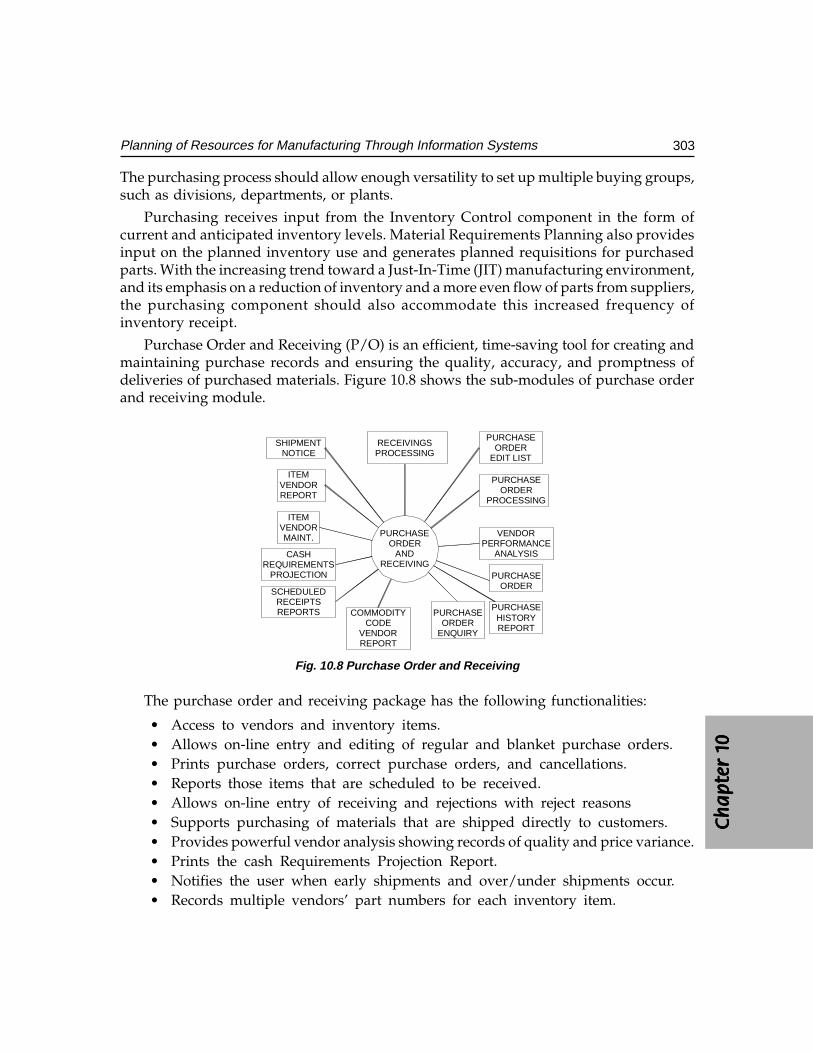
Ch
ap
ter
1C
ha
pte
r 1
Ch
ap
ter
1C
ha
pte
r 1
Ch
ap
ter
1 0000 0
303Planning of Resources for Manufacturing Through Information Systems
The purchasing process should allow enough versatility to set up multiple buying groups,such as divisions, departments, or plants.
Purchasing receives input from the Inventory Control component in the form ofcurrent and anticipated inventory levels. Material Requirements Planning also providesinput on the planned inventory use and generates planned requisitions for purchasedparts. With the increasing trend toward a Just-In-Time (JIT) manufacturing environment,and its emphasis on a reduction of inventory and a more even flow of parts from suppliers,the purchasing component should also accommodate this increased frequency ofinventory receipt.
Purchase Order and Receiving (P/O) is an efficient, time-saving tool for creating andmaintaining purchase records and ensuring the quality, accuracy, and promptness ofdeliveries of purchased materials. Figure 10.8 shows the sub-modules of purchase orderand receiving module.
SHIPMENTNOTICE
RECEIVINGSPROCESSING
ITEMVENDORREPORT
ITEMVENDORMAINT.
CASHREQUIREMENTS
PROJECTION
SCHEDULEDRECEIPTSREPORTS COMMODITY
CODEVENDORREPORT
PURCHASEORDER
ENQUIRY
PURCHASEHISTORYREPORT
PURCHASEORDER
VENDORPERFORMANCE
ANALYSIS
PURCHASEORDER
PROCESSING
PURCHASEORDER
EDIT LIST
PURCHASEORDER
ANDRECEIVING
Fig. 10.8 Purchase Order and Receiving
The purchase order and receiving package has the following functionalities:
• Access to vendors and inventory items.• Allows on-line entry and editing of regular and blanket purchase orders.• Prints purchase orders, correct purchase orders, and cancellations.• Reports those items that are scheduled to be received.• Allows on-line entry of receiving and rejections with reject reasons• Supports purchasing of materials that are shipped directly to customers.• Provides powerful vendor analysis showing records of quality and price variance.• Prints the cash Requirements Projection Report.• Notifies the user when early shipments and over/under shipments occur.• Records multiple vendors’ part numbers for each inventory item.
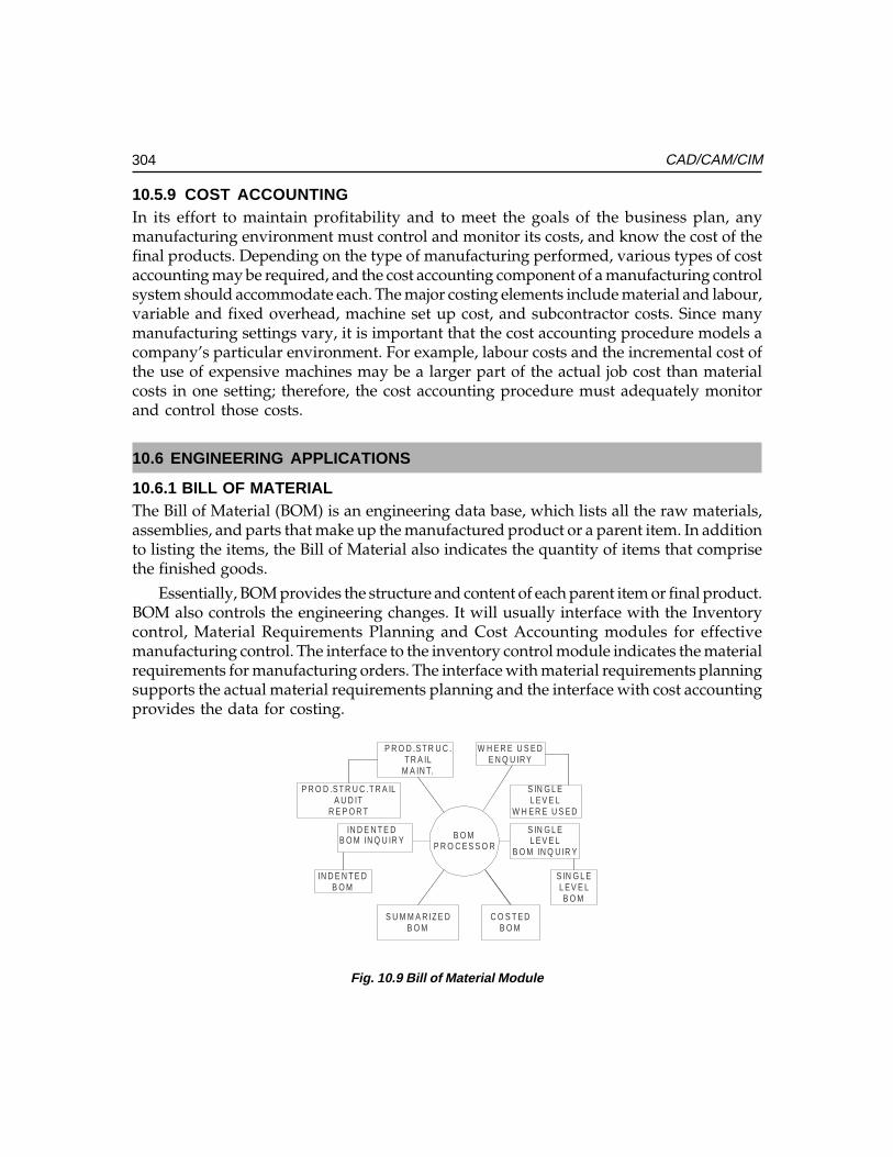
304 CAD/CAM/CIM
10.5.9 COST ACCOUNTINGIn its effort to maintain profitability and to meet the goals of the business plan, anymanufacturing environment must control and monitor its costs, and know the cost of thefinal products. Depending on the type of manufacturing performed, various types of costaccounting may be required, and the cost accounting component of a manufacturing controlsystem should accommodate each. The major costing elements include material and labour,variable and fixed overhead, machine set up cost, and subcontractor costs. Since manymanufacturing settings vary, it is important that the cost accounting procedure models acompany’s particular environment. For example, labour costs and the incremental cost ofthe use of expensive machines may be a larger part of the actual job cost than materialcosts in one setting; therefore, the cost accounting procedure must adequately monitorand control those costs.
10.6 ENGINEERING APPLICATIONS
10.6.1 BILL OF MATERIALThe Bill of Material (BOM) is an engineering data base, which lists all the raw materials,assemblies, and parts that make up the manufactured product or a parent item. In additionto listing the items, the Bill of Material also indicates the quantity of items that comprisethe finished goods.
Essentially, BOM provides the structure and content of each parent item or final product.BOM also controls the engineering changes. It will usually interface with the Inventorycontrol, Material Requirements Planning and Cost Accounting modules for effectivemanufacturing control. The interface to the inventory control module indicates the materialrequirements for manufacturing orders. The interface with material requirements planningsupports the actual material requirements planning and the interface with cost accountingprovides the data for costing.
P R O D .S T R U C .T R A ILA U D IT
R E P O R T
P R O D .S T R U C .T R A IL
M A IN T.
W H E R E U S E DE N Q U IR Y
S IN G L EL E V E L
W H E R E U S E D
IN D E N T E DB O M
IN D E N T E DB O M IN Q U IR Y
S IN G L EL E V E L
B O M IN Q U IR Y
S IN G L EL E V E LB O M
S U M M A R IZ E DB O M
C O S T E DB O M
B O MP R O C E S S O R
Fig. 10.9 Bill of Material Module
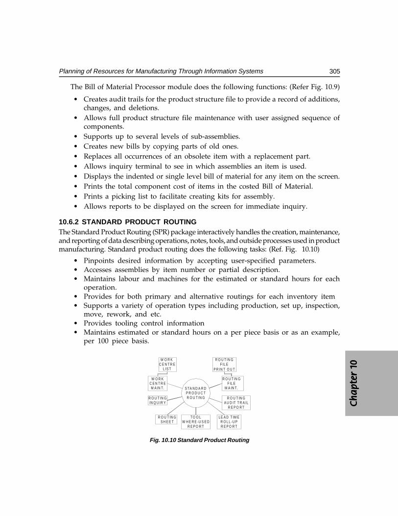
Ch
ap
ter
1C
ha
pte
r 1
Ch
ap
ter
1C
ha
pte
r 1
Ch
ap
ter
1 0000 0
305Planning of Resources for Manufacturing Through Information Systems
The Bill of Material Processor module does the following functions: (Refer Fig. 10.9)
• Creates audit trails for the product structure file to provide a record of additions,changes, and deletions.
• Allows full product structure file maintenance with user assigned sequence ofcomponents.
• Supports up to several levels of sub-assemblies.• Creates new bills by copying parts of old ones.• Replaces all occurrences of an obsolete item with a replacement part.• Allows inquiry terminal to see in which assemblies an item is used.• Displays the indented or single level bill of material for any item on the screen.• Prints the total component cost of items in the costed Bill of Material.• Prints a picking list to facilitate creating kits for assembly.• Allows reports to be displayed on the screen for immediate inquiry.
10.6.2 STANDARD PRODUCT ROUTINGThe Standard Product Routing (SPR) package interactively handles the creation, maintenance,and reporting of data describing operations, notes, tools, and outside processes used in productmanufacturing. Standard product routing does the following tasks: (Ref. Fig. 10.10)
• Pinpoints desired information by accepting user-specified parameters.• Accesses assemblies by item number or partial description.• Maintains labour and machines for the estimated or standard hours for each
operation.• Provides for both primary and alternative routings for each inventory item• Supports a variety of operation types including production, set up, inspection,
move, rework, and etc.• Provides tooling control information• Maintains estimated or standard hours on a per piece basis or as an example,
per 100 piece basis.
W O R K C E N T R E
L IS T
W O R KC E N T R EM A IN T.
R O U T IN GF IL E
R O U T IN GF IL E
M A IN T.
R O U T IN GIN Q U IR Y
R O U T IN GS H E E T
TO O LW H E R E -U S E D
R E P O R T
L E A D T IM ER O L L -U PR E P O R T
R O U T IN GA U D IT T R A IL
R E P O R T
S TA N D A R DP R O D U C TR O U T IN G
P R IN T O U T
Fig. 10.10 Standard Product Routing
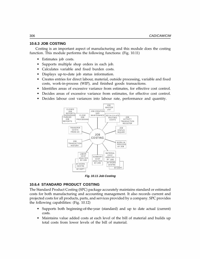
306 CAD/CAM/CIM
10.6.3 JOB COSTINGCosting is an important aspect of manufacturing and this module does the costing
function. This module performs the following functions: (Fig. 10.11)
• Estimates job costs.• Supports multiple shop orders in each job.• Calculates variable and fixed burden costs.• Displays up-to-date job status information.• Creates entries for direct labour, material, outside processing, variable and fixed
costs, work-in-process (WIP), and finished goods transactions.• Identifies areas of excessive variance from estimates, for effective cost control.• Decides areas of excessive variance from estimates, for effective cost control.• Decides labour cost variances into labour rate, performance and quantity.
JO B C R E AT IO NA N D
M A IN TE NA NC ECL O SEJO B
P R O C ES SI NG
T RA NS FE RCO ST S
F RO M A /C
JO BT RA NS AC TI O N
HI ST O RY
LAB O R CO ST
A N A LY SI SB Y JO B
S U M M A R YCO ST
A N A LY SI SB Y JO B
M ATE R IALCO ST
A N A LY SI SB Y JO B
W O R K INP R O C ES SB Y JO B
JO BS TAT U SIN Q U IRY
RE CA LC U LATERO UT IN G
CO ST SP U RG ED
JO BRE P O R T S
CL O SE DJO B
RE P O R T S
JO B M A ST E R
LIS T
JO BA C T IV IT Y
T RA NS AC TI O NRE G IST ER
B Y W O R K CE NT R E
B Y D EP T
B Y W O R KCE NT R E
B Y D EP T
JOBCO ST IN G
Fig. 10.11 Job Costing
10.6.4 STANDARD PRODUCT COSTINGThe Standard Product Costing (SPC) package accurately maintains standard or estimatedcosts for both manufacturing and accounting management. It also records current andprojected costs for all products, parts, and services provided by a company. SPC providesthe following capabilities: (Fig. 10.12)
• Supports both beginning-of-the-year (standard) and up to date actual (current)costs.
• Maintains value added costs at each level of the bill of material and builds uptotal costs from lower levels of the bill of material.
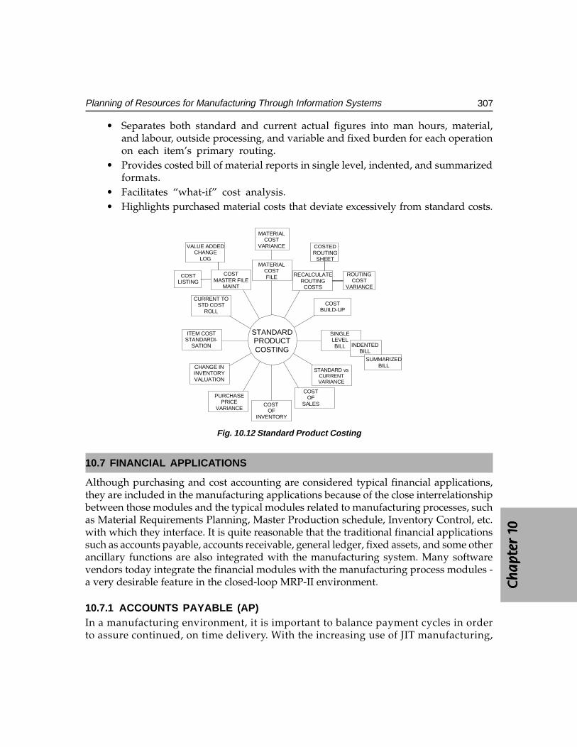
Ch
ap
ter
1C
ha
pte
r 1
Ch
ap
ter
1C
ha
pte
r 1
Ch
ap
ter
1 0000 0
307Planning of Resources for Manufacturing Through Information Systems
• Separates both standard and current actual figures into man hours, material,and labour, outside processing, and variable and fixed burden for each operationon each item’s primary routing.
• Provides costed bill of material reports in single level, indented, and summarizedformats.
• Facilitates “what-if” cost analysis.• Highlights purchased material costs that deviate excessively from standard costs.
STANDARD vsCURRENTVARIANCE
MATERIALCOSTFILE
COSTMASTER FILE
MAINT
CURRENT TOSTD COST
ROLL
ITEM COSTSTANDARDI-
SATION
CHANGE ININVENTORYVALUATION
PURCHASEPRICE
VARIANCECOST
OFINVENTORY
COSTOF
SALES
SINGLELEVELBILL
COSTBUILD-UP
RECALCULATEROUTING
COSTS
INDENTEDBILL
SUMMARIZEDBILL
COSTEDROUTING
SHEET
ROUTINGCOST
VARIANCE
MATERIALCOST
VARIANCEVALUE ADDEDCHANGE
LOG
COSTLISTING
STANDARDPRODUCTCOSTING
Fig. 10.12 Standard Product Costing
10.7 FINANCIAL APPLICATIONS
Although purchasing and cost accounting are considered typical financial applications,they are included in the manufacturing applications because of the close interrelationshipbetween those modules and the typical modules related to manufacturing processes, suchas Material Requirements Planning, Master Production schedule, Inventory Control, etc.with which they interface. It is quite reasonable that the traditional financial applicationssuch as accounts payable, accounts receivable, general ledger, fixed assets, and some otherancillary functions are also integrated with the manufacturing system. Many softwarevendors today integrate the financial modules with the manufacturing process modules -a very desirable feature in the closed-loop MRP-II environment.
10.7.1 ACCOUNTS PAYABLE (AP)In a manufacturing environment, it is important to balance payment cycles in orderto assure continued, on time delivery. With the increasing use of JIT manufacturing,
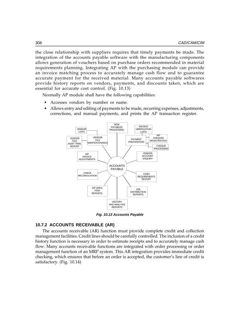
308 CAD/CAM/CIM
the close relationship with suppliers requires that timely payments be made. Theintegration of the accounts payable software with the manufacturing componentsallows generation of vouchers based on purchase orders recommended in materialrequirements planning. Integrating AP with the purchasing module can providean invoice matching process to accurately manage cash flow and to guaranteeaccurate payment for the received material. Many accounts payable softwaresprovide history reports on vendors, payments, and discounts taken, which areessential for accurate cost control. (Fig. 10.13)
Normally AP module shall have the following capabilities:
• Accesses vendors by number or name.• Allows entry and editing of payments to be made, recurring expenses, adjustments,
corrections, and manual payments, and prints the AP transaction register.
CHECKRECONCILIATION
NEWPAYABLES
PROCESSING
PAYMENTPREPARATION
VENDORACCOUNTENQUIRY
CASHREQUIREMENTS
REPORT
JOBDISTRIBUTION
REPORTS
HISTORYAND ANALYSIS
REPORTS
A/P OPENITEM
REPORTS
A/PINVOICE
ADJUSTMENTS
VENDORFILE
MAINTENTENANCE
INVOICEVERIFICATION
LISTS
A/PCHEQUES
REGISTRATION
CHEQUEPROCESSING
VENDORLISTS
VENDORFILE
AUDIT TRAILREPORT
ACCOUNTSPAYABLE
Fig. 10.13 Accounts Payable
10.7.2 ACCOUNTS RECEIVABLE (AR)The accounts receivable (AR) function must provide complete credit and collection
management facilities. Credit lines should be carefully controlled. The inclusion of a credithistory function is necessary in order to estimate receipts and to accurately manage cashflow. Many accounts receivable functions are integrated with order processing or ordermanagement function of an MRP system. This AR integration provides immediate creditchecking, which ensures that before an order is accepted, the customer’s line of credit issatisfactory. (Fig. 10.14)
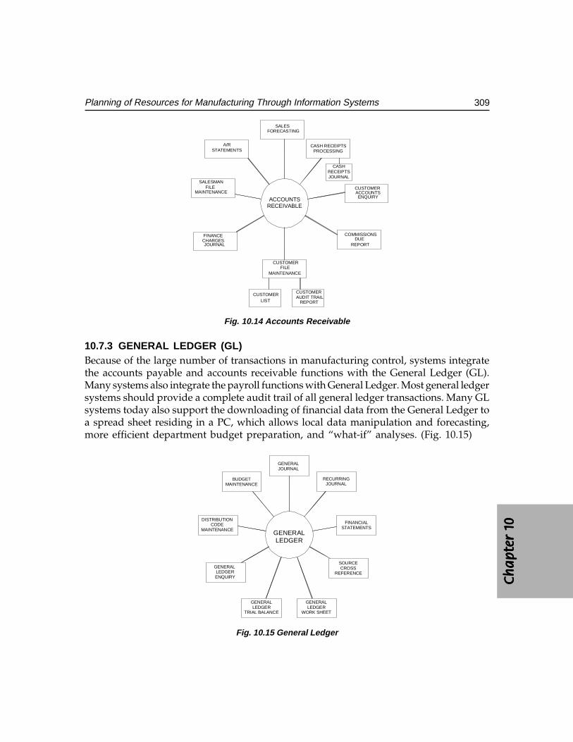
Ch
ap
ter
1C
ha
pte
r 1
Ch
ap
ter
1C
ha
pte
r 1
Ch
ap
ter
1 0000 0
309Planning of Resources for Manufacturing Through Information Systems
ACCOUNTSRECEIVABLE
CASH RECEIPTSPROCESSING
CUSTOMERACCOUNTSENQUIRY
COMMISSIONSDUE
REPORT
FINANCECHARGESJOURNAL
SALESMANFILE
MAINTENANCE
CUSTOMERFILE
MAINTENANCE
SALESFORECASTING
A/RSTATEMENTS
CASHRECEIPTSJOURNAL
CUSTOMERLIST
CUSTOMERAUDIT TRAIL
REPORT
Fig. 10.14 Accounts Receivable
10.7.3 GENERAL LEDGER (GL)Because of the large number of transactions in manufacturing control, systems integratethe accounts payable and accounts receivable functions with the General Ledger (GL).Many systems also integrate the payroll functions with General Ledger. Most general ledgersystems should provide a complete audit trail of all general ledger transactions. Many GLsystems today also support the downloading of financial data from the General Ledger toa spread sheet residing in a PC, which allows local data manipulation and forecasting,more efficient department budget preparation, and “what-if” analyses. (Fig. 10.15)
GENERALLEDGER
TRIAL BALANCE
GENERALLEDGER
WORK SHEET
SOURCECROSS
REFERENCE
FINANCIALSTATEMENTS
RECURRINGJOURNAL
GENERALJOURNAL
BUDGETMAINTENANCE
DISTRIBUTIONCODE
MAINTENANCE
GENERAL LEDGERENQUIRY
GENERALLEDGER
Fig. 10.15 General Ledger
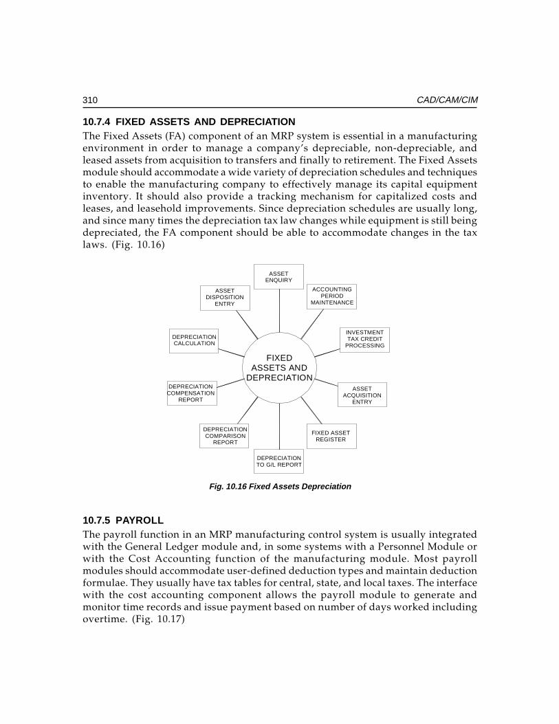
310 CAD/CAM/CIM
10.7.4 FIXED ASSETS AND DEPRECIATIONThe Fixed Assets (FA) component of an MRP system is essential in a manufacturingenvironment in order to manage a company’s depreciable, non-depreciable, andleased assets from acquisition to transfers and finally to retirement. The Fixed Assetsmodule should accommodate a wide variety of depreciation schedules and techniquesto enable the manufacturing company to effectively manage its capital equipmentinventory. It should also provide a tracking mechanism for capitalized costs andleases, and leasehold improvements. Since depreciation schedules are usually long,and since many times the depreciation tax law changes while equipment is still beingdepreciated, the FA component should be able to accommodate changes in the taxlaws. (Fig. 10.16)
FIXEDASSETS AND
DEPRECIATION
DEPRECIATIONTO G/L REPORT
FIXED ASSETREGISTER
ASSETACQUISITION
ENTRY
INVESTMENTTAX CREDIT
PROCESSING
ACCOUNTINGPERIOD
MAINTENANCE
ASSETENQUIRY
ASSETDISPOSITION
ENTRY
DEPRECIATIONCALCULATION
DEPRECIATIONCOMPENSATION
REPORT
DEPRECIATIONCOMPARISON
REPORT
Fig. 10.16 Fixed Assets Depreciation
10.7.5 PAYROLLThe payroll function in an MRP manufacturing control system is usually integratedwith the General Ledger module and, in some systems with a Personnel Module orwith the Cost Accounting function of the manufacturing module. Most payrollmodules should accommodate user-defined deduction types and maintain deductionformulae. They usually have tax tables for central, state, and local taxes. The interfacewith the cost accounting component allows the payroll module to generate andmonitor time records and issue payment based on number of days worked includingovertime. (Fig. 10.17)
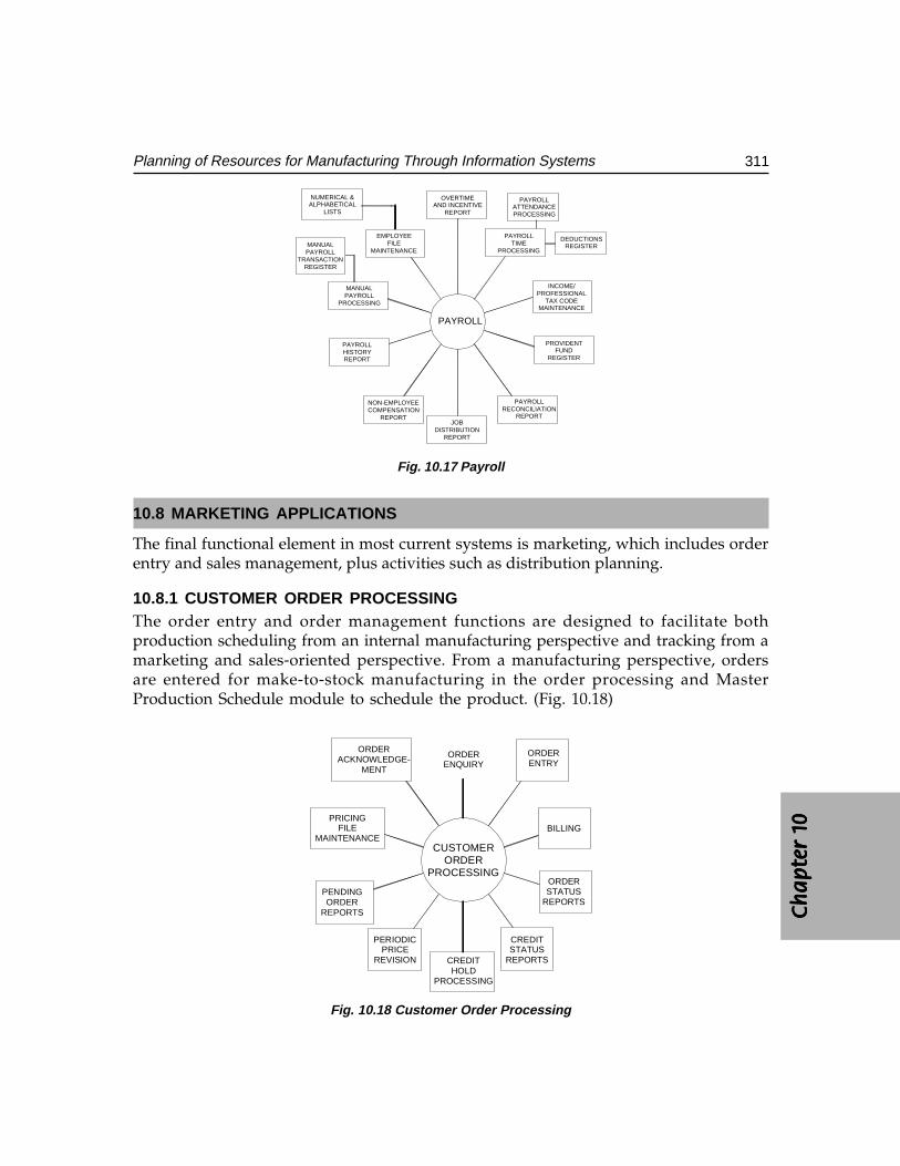
Ch
ap
ter
1C
ha
pte
r 1
Ch
ap
ter
1C
ha
pte
r 1
Ch
ap
ter
1 0000 0
311Planning of Resources for Manufacturing Through Information Systems
PAYROLL
OVERTIMEAND INCENTIVE
REPORT
PAYROLLTIME
PROCESSING
INCOME/PROFESSIONAL
TAX CODEMAINTENANCE
PROVIDENTFUND
REGISTER
PAYROLLRECONCILIATION
REPORTJOB
DISTRIBUTIONREPORT
NON-EMPLOYEECOMPENSATION
REPORT
PAYROLLHISTORYREPORT
MANUALPAYROLL
PROCESSING
EMPLOYEEFILE
MAINTENANCE
NUMERICAL &ALPHABETICAL
LISTS
MANUALPAYROLL
TRANSACTIONREGISTER
PAYROLLATTENDANCEPROCESSING
DEDUCTIONSREGISTER
Fig. 10.17 Payroll
10.8 MARKETING APPLICATIONS
The final functional element in most current systems is marketing, which includes orderentry and sales management, plus activities such as distribution planning.
10.8.1 CUSTOMER ORDER PROCESSINGThe order entry and order management functions are designed to facilitate bothproduction scheduling from an internal manufacturing perspective and tracking from amarketing and sales-oriented perspective. From a manufacturing perspective, ordersare entered for make-to-stock manufacturing in the order processing and MasterProduction Schedule module to schedule the product. (Fig. 10.18)
ORDERENQUIRY
ORDERENTRY
BILLING
ORDERSTATUS
REPORTS
CREDITSTATUS
REPORTSCREDITHOLD
PROCESSING
PERIODICPRICE
REVISION
PENDINGORDER
REPORTS
PRICINGFILE
MAINTENANCE
ORDERACKNOWLEDGE-
MENT
CUSTOMERORDER
PROCESSING
Fig. 10.18 Customer Order Processing
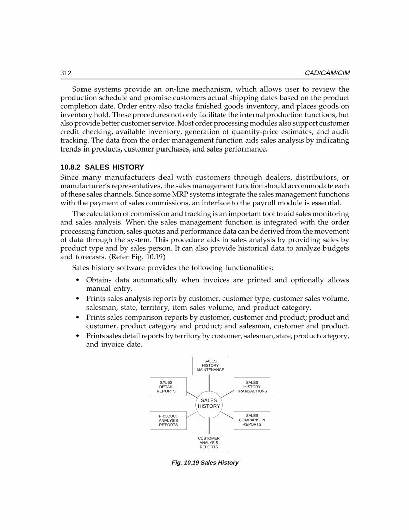
312 CAD/CAM/CIM
Some systems provide an on-line mechanism, which allows user to review theproduction schedule and promise customers actual shipping dates based on the productcompletion date. Order entry also tracks finished goods inventory, and places goods oninventory hold. These procedures not only facilitate the internal production functions, butalso provide better customer service. Most order processing modules also support customercredit checking, available inventory, generation of quantity-price estimates, and audittracking. The data from the order management function aids sales analysis by indicatingtrends in products, customer purchases, and sales performance.
10.8.2 SALES HISTORYSince many manufacturers deal with customers through dealers, distributors, ormanufacturer’s representatives, the sales management function should accommodate eachof these sales channels. Since some MRP systems integrate the sales management functionswith the payment of sales commissions, an interface to the payroll module is essential.
The calculation of commission and tracking is an important tool to aid sales monitoringand sales analysis. When the sales management function is integrated with the orderprocessing function, sales quotas and performance data can be derived from the movementof data through the system. This procedure aids in sales analysis by providing sales byproduct type and by sales person. It can also provide historical data to analyze budgetsand forecasts. (Refer Fig. 10.19)
Sales history software provides the following functionalities:
• Obtains data automatically when invoices are printed and optionally allowsmanual entry.
• Prints sales analysis reports by customer, customer type, customer sales volume,salesman, state, territory, item sales volume, and product category.
• Prints sales comparison reports by customer, customer and product; product andcustomer, product category and product; and salesman, customer and product.
• Prints sales detail reports by territory by customer, salesman, state, product category,and invoice date.
SALESHISTORY
SALESCOMPARISON
REPORTS
SALESHISTORY
TRANSACTIONS
SALESHISTORY
MAINTENANCE
SALESDETAIL
REPORTS
PRODUCTANALYSISREPORTS
CUSTOMERANALYSISREPORTS
Fig. 10.19 Sales History
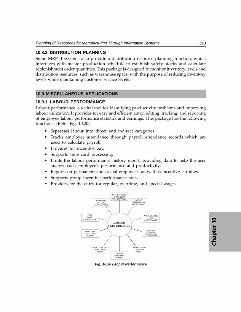
Ch
ap
ter
1C
ha
pte
r 1
Ch
ap
ter
1C
ha
pte
r 1
Ch
ap
ter
1 0000 0
313Planning of Resources for Manufacturing Through Information Systems
10.8.3 DISTRIBUTION PLANNINGSome MRP-II systems also provide a distribution resource planning function, whichinterfaces with master production schedule to establish safety stocks and calculatereplenishment order quantities. This package is designed to monitor inventory levels anddistribution resources, such as warehouse space, with the purpose of reducing inventorylevels while maintaining customer service levels.
10.9 MISCELLANEOUS APPLICATIONS
10.9.1 LABOUR PERFORMANCELabour performance is a vital tool for identifying productivity problems and improvinglabour utilization. It provides for easy and efficient entry, editing, tracking, and reportingof employee labour performance statistics and earnings. This package has the followingfunctions: (Refer Fig. 10.20)
• Separates labour into direct and indirect categories.• Tracks employee attendance through payroll attendance records which are
used to calculate payroll.• Provides for incentive pay.• Supports time card processing.• Prints the labour performance history report, providing data to help the user
analyze each employee’s performance and productivity.• Reports on permanent and casual employees as well as incentive earnings.• Supports group incentive performance rates.• Provides for the entry for regular, overtime, and special wages.
DATA CAPTUREFOR LABOUR
PERFORMANCELABOUR
TRANSACTIONPROCESSING
WORK CENTREFILE
MAINTENANCE
LABOUREARNINGS
PROCESSING
WORK CENTRECAPACITYREPORT
LABOUREARNINGSREPORT
EMPLOYEE DATAAUDIT TRAIL
REPORT
TIME CARDAUDIT TRAIL
REPORT
TIMECARD
PROCESSING
EMPLOYEEDATA FILE
MAINTENANCE
LABOURPERFORMANCE
Fig. 10.20 Labour Performance
314 CAD/CAM/CIM
10.10 COMMON ACRONYMS USED IN AN MRP-II ENVIRONMENT
AP (A/P) - Accounts payable
AR (A/R) - Accounts Receivable
BOM (BOMP) - Bill Of Material(S) (Bill of Material(S)
Processor)
CRP - Capacity Requirements Planning
DRP - Distribution Requirements Planning
FA (F/A) - Fixed Assets
GL (G/L) - General Ledger
IC (I/C) - Inventory Control
JIT - Just in Time Manufacturing
MPS - Master Production Scheduling
MRP - Material Requirements Planning
MRP-II - Manufacturing Resources Planning
OE (O/E) - Order Entry
OP (O/P) - Order Processing
PAC - Production Activity Control
PR (P/R) - Payroll
PO (P/O) - Purchase Order
RRP - Resource Requirements Planning
SFC - Shop Floor Control
10.11 STATUS OF MRP-II SOFTWARE
Many vendors advertise their manufacturing control system as “the cornerstone of CIMsystem”, and feature state of the art interfaces and modules. Many manufactures, however,are still struggling with too much inventory and incorrect bills of materials; they are notyet ready for the factory of the future. It must be stressed that MRP-II, or CIM, or JIT alonewill not solve all manufacturing problems. Putting the problems on a computer will onlyautomate the solution.
First, manufacturers should identify and begin to solve their problems whileimplementing a good, basic MRP-II. This may involve a year or two of updating their billsof material to reflect the real world, reducing inventories, and cutting lead times. They
Ch
ap
ter
1C
ha
pte
r 1
Ch
ap
ter
1C
ha
pte
r 1
Ch
ap
ter
1 0000 0
315Planning of Resources for Manufacturing Through Information Systems
can then gradually introduce basic just-in-time (JIT) techniques, such as having a goodrelationship with one or two reliable suppliers, reducing lot sizes, and implementingtotal quality control programs.
Surprisingly, many manufacturers are just now discovering that their employeesare a great resource which they have all along virtually ignored. Sadly, somemanufacturers are yet to discover it. No one knows where the waste and inefficiencyexists better than people on the shop floor. Nobody else is in a better position to suggestways to stop it. The Japanese discovered this, and used this in quality circles and totalquality control (TQM) to correct the design and manufacturing problems. Theimmediate future of manufacturing in India depends on getting employees more andmore involved in the decision making and quality of the products. To do this uphilltask, top management has to get involved, delegate some of their powers, and letemployees know that they can make a difference.
In the long run, the adoption of JIT is inevitable. To be competitive, Indianmanufacturers must reduce their lead times, become more flexible to satisfy a rapidlychanging market, and institute better quality control methods-all the hallmarks of JIT.
In the past, vendors advertised systems that were upgradeable to larger systems.Today, more and more software vendors are realizing the importance of personalcomputers in the office and industry environment. Most offer some facility to downloadinformation collected through the MRP system to PCs for use in spreadsheets and reports.
This trend towards smaller, distributed (but linked) systems will continue. With theincredible power and ease of use of today’s mini and personal computers, one will beseeing fewer mainframe installations and more minicomputers and networking of personalcomputers. PC’s, unlike mainframes (and to some extent minis), do not require an extensiveMIS department. PCs can be used independently for word processing or data manipulationwhile still being tied into a network with a central file server. Networked systems canexpand or shrink to fit the needs of the company.
10.12 DYNAMIC ENTERPRISES
Global competition forces manufacturing companies to constantly strive for improvementin quality and reduction in price and product development time. The manufacturingcompanies, therefore, are always on the look out for strategies which will help them toachieve these objectives. During the last few decades, the focus of the manufacturing strategyhas been shifting from one innovation to another in order to improve the flexibility whichis essential for supplying products, which meets the satisfaction of customers. Theseinnovations are shown in Fig. 10.21.
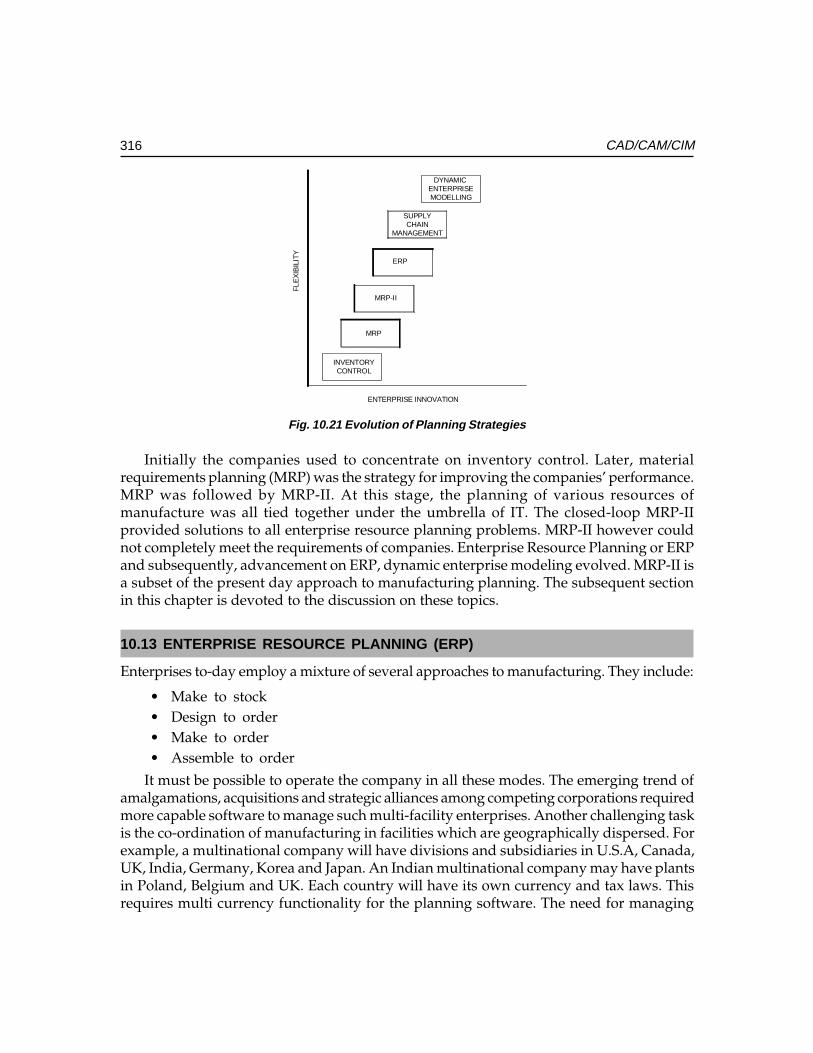
316 CAD/CAM/CIM
DYNAMIC ENTERPRISEMODELLING
SUPPLYCHAIN
MANAGEMENT
ERP
MRP-II
MRP
INVENTORYCONTROL
ENTERPRISE INNOVATION
FLE
XIB
ILIT
Y
Fig. 10.21 Evolution of Planning Strategies
Initially the companies used to concentrate on inventory control. Later, materialrequirements planning (MRP) was the strategy for improving the companies’ performance.MRP was followed by MRP-II. At this stage, the planning of various resources ofmanufacture was all tied together under the umbrella of IT. The closed-loop MRP-IIprovided solutions to all enterprise resource planning problems. MRP-II however couldnot completely meet the requirements of companies. Enterprise Resource Planning or ERPand subsequently, advancement on ERP, dynamic enterprise modeling evolved. MRP-II isa subset of the present day approach to manufacturing planning. The subsequent sectionin this chapter is devoted to the discussion on these topics.
10.13 ENTERPRISE RESOURCE PLANNING (ERP)
Enterprises to-day employ a mixture of several approaches to manufacturing. They include:
• Make to stock• Design to order• Make to order• Assemble to order
It must be possible to operate the company in all these modes. The emerging trend ofamalgamations, acquisitions and strategic alliances among competing corporations requiredmore capable software to manage such multi-facility enterprises. Another challenging taskis the co-ordination of manufacturing in facilities which are geographically dispersed. Forexample, a multinational company will have divisions and subsidiaries in U.S.A, Canada,UK, India, Germany, Korea and Japan. An Indian multinational company may have plantsin Poland, Belgium and UK. Each country will have its own currency and tax laws. Thisrequires multi currency functionality for the planning software. The need for managing
Ch
ap
ter
1C
ha
pte
r 1
Ch
ap
ter
1C
ha
pte
r 1
Ch
ap
ter
1 0000 0
317Planning of Resources for Manufacturing Through Information Systems
the entire enterprise within a more global, tightly integrated closed-loop solution has ledto the evolution of ERP software.
The core activity in ERP is the creation of an integrated data model, coveringemployees, customers, suppliers etc. A distinguishing feature of the ERP software is thatit incorporates best practices. This means that the manufacturing solution developedusing ERP is an optimum one.
The implementation of an ERP system includes the following stages:
i. Definition of the scope of the projectii. Identification of the objectives and deliverables
iii. Project organization• Identifying an executive responsible for successful implementation of ERP• Establish a senior management steering committee• Establish a project team• Define the role of consultants
iv. Work plan developmentv. Assessment of the business of the company - where it is to day and where it
should govi. Education of key managersvii. Cost/benefit analysis
10.13.1 MODULES IN TYPICAL ERP SOFTWAREThe important modules in typical ERP software are:
i.i.i.i.i. Finance ModuleFinance ModuleFinance ModuleFinance ModuleFinance ModuleThe finance module extracts financial transactions from the sales andmanufacturing areas and posts them to the general ledger. The main elementsof finance module are:
General ledgerAccounts payableAccounts receivableCash managementFixed AssetsFinancial statementBudgetCost allocation
ii.ii.ii.ii.ii. Distribution ModuleDistribution ModuleDistribution ModuleDistribution ModuleDistribution ModuleThis module manages finished goods, raw materials and services. Sales ordersare managed by this module. Inventory control, location control, Distribution
318 CAD/CAM/CIM
Requirements planning and replenishment control are part of distributionmodule.
The business objects of this module are:The business objects of this module are:The business objects of this module are:The business objects of this module are:The business objects of this module are:Item controlCost accountingPurchase controlSales controlSales and marketing informationElectronic data interchangeReplenishment order controlInventory controlLot controlLocation controlDistribution requirements planning
iii.iii.iii.iii.iii. Manufacturing ModuleManufacturing ModuleManufacturing ModuleManufacturing ModuleManufacturing ModuleThis module is designed to control all the operations related to manufacture.The business objectives of this module are:
Engineering Data ManagementItem controlBill of materialsRoutingMaster production scheduleMaterials requirement planningCapacity requirement planningRepetitive manufacturingShop floor controlHours accountingProject budgetProduct configuration and classificationProject controlQuality management
iviviviviv..... Service ModuleService ModuleService ModuleService ModuleService ModuleService module deals with repair and warranty related activities. The functionsof this module are:
Installation controlContract controlService order control
Ch
ap
ter
1C
ha
pte
r 1
Ch
ap
ter
1C
ha
pte
r 1
Ch
ap
ter
1 0000 0
319Planning of Resources for Manufacturing Through Information Systems
Service analysis control
v.v.v.v.v. Transportation moduleTransportation moduleTransportation moduleTransportation moduleTransportation module
The functions of this module are:Employee controlAddress controlFleet managementFuel controlHours and expense controlTransport controlPacking controlWarehouse control
vi.vi.vi.vi.vi. Process ModuleProcess ModuleProcess ModuleProcess ModuleProcess ModuleThe process module helps companies to keep track of the manufacture ofproducts.
vii.vii.vii.vii.vii. Project ModuleProject ModuleProject ModuleProject ModuleProject ModuleThe project module consists of
EstimatingDefinitionBudgetPlanningRequirementProgressMonitoringInvoicing
viii.viii.viii.viii.viii. TTTTTools Moduleools Moduleools Moduleools Moduleools ModuleTools Module covers the following:
Software installationApplication configurationUser managementDevice managementJob managementDatabase managementAudit managementText managementMenu managementSQL queriesApplication development and customizationDocumentation
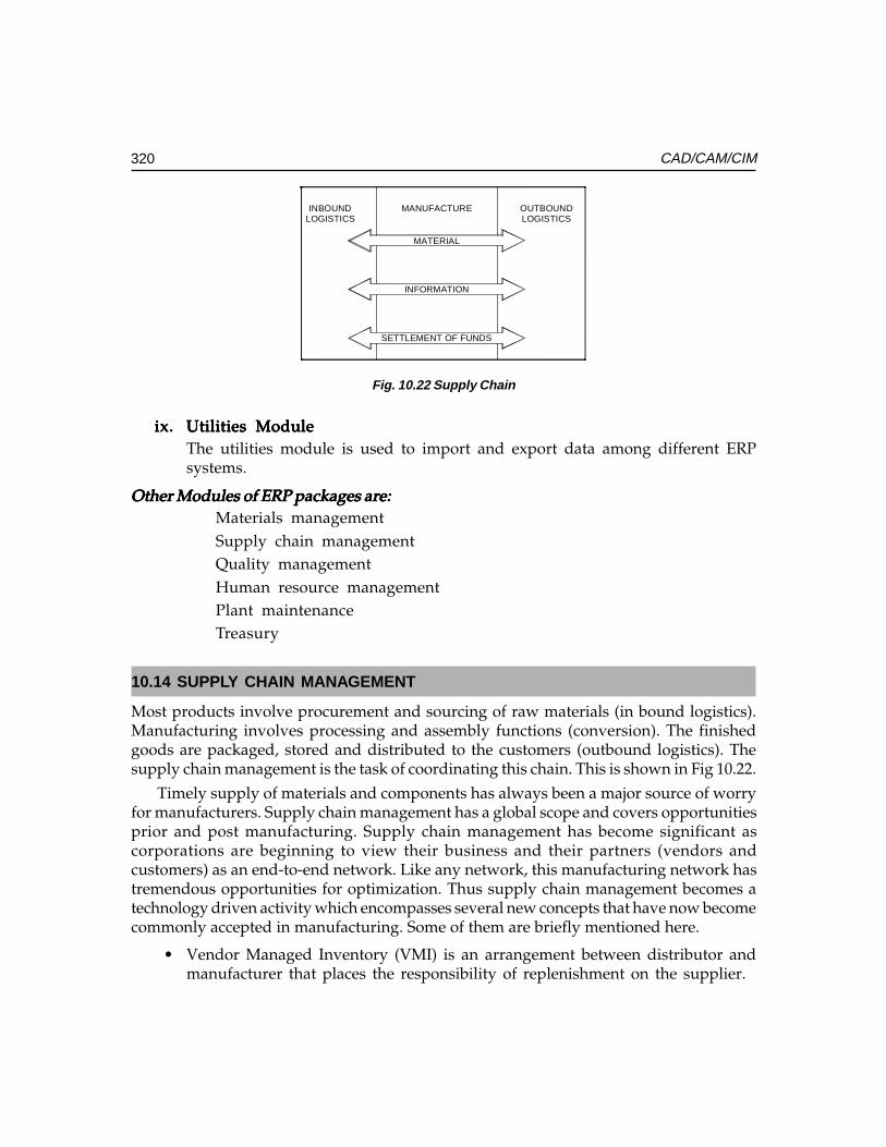
320 CAD/CAM/CIM
SETTLEMENT OF FUNDS
MANUFACTURE
MATERIAL
INFORMATION
INBOUNDLOGISTICS
OUTBOUNDLOGISTICS
Fig. 10.22 Supply Chain
ix.ix.ix.ix.ix. Utilities ModuleUtilities ModuleUtilities ModuleUtilities ModuleUtilities ModuleThe utilities module is used to import and export data among different ERPsystems.
Other Modules of ERP packages are:Other Modules of ERP packages are:Other Modules of ERP packages are:Other Modules of ERP packages are:Other Modules of ERP packages are:Materials managementSupply chain managementQuality managementHuman resource managementPlant maintenanceTreasury
10.14 SUPPLY CHAIN MANAGEMENT
Most products involve procurement and sourcing of raw materials (in bound logistics).Manufacturing involves processing and assembly functions (conversion). The finishedgoods are packaged, stored and distributed to the customers (outbound logistics). Thesupply chain management is the task of coordinating this chain. This is shown in Fig 10.22.
Timely supply of materials and components has always been a major source of worryfor manufacturers. Supply chain management has a global scope and covers opportunitiesprior and post manufacturing. Supply chain management has become significant ascorporations are beginning to view their business and their partners (vendors andcustomers) as an end-to-end network. Like any network, this manufacturing network hastremendous opportunities for optimization. Thus supply chain management becomes atechnology driven activity which encompasses several new concepts that have now becomecommonly accepted in manufacturing. Some of them are briefly mentioned here.
• Vendor Managed Inventory (VMI) is an arrangement between distributor andmanufacturer that places the responsibility of replenishment on the supplier.
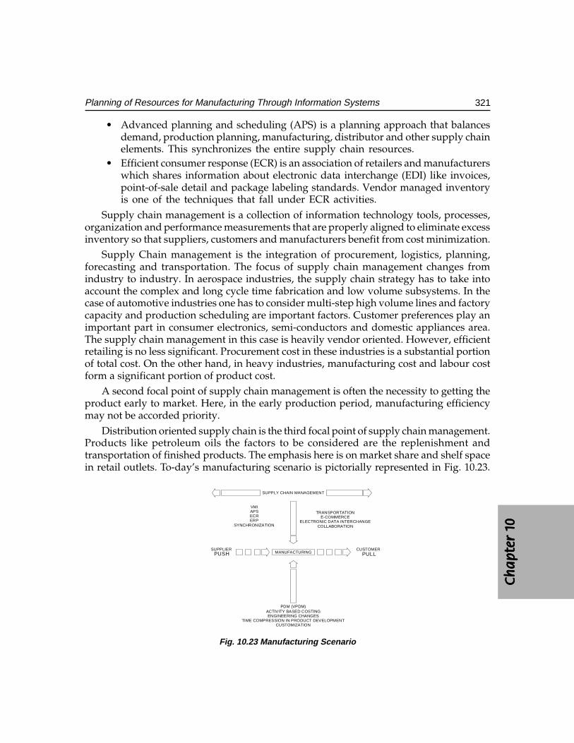
Ch
ap
ter
1C
ha
pte
r 1
Ch
ap
ter
1C
ha
pte
r 1
Ch
ap
ter
1 0000 0
321Planning of Resources for Manufacturing Through Information Systems
• Advanced planning and scheduling (APS) is a planning approach that balancesdemand, production planning, manufacturing, distributor and other supply chainelements. This synchronizes the entire supply chain resources.
• Efficient consumer response (ECR) is an association of retailers and manufacturerswhich shares information about electronic data interchange (EDI) like invoices,point-of-sale detail and package labeling standards. Vendor managed inventoryis one of the techniques that fall under ECR activities.
Supply chain management is a collection of information technology tools, processes,organization and performance measurements that are properly aligned to eliminate excessinventory so that suppliers, customers and manufacturers benefit from cost minimization.
Supply Chain management is the integration of procurement, logistics, planning,forecasting and transportation. The focus of supply chain management changes fromindustry to industry. In aerospace industries, the supply chain strategy has to take intoaccount the complex and long cycle time fabrication and low volume subsystems. In thecase of automotive industries one has to consider multi-step high volume lines and factorycapacity and production scheduling are important factors. Customer preferences play animportant part in consumer electronics, semi-conductors and domestic appliances area.The supply chain management in this case is heavily vendor oriented. However, efficientretailing is no less significant. Procurement cost in these industries is a substantial portionof total cost. On the other hand, in heavy industries, manufacturing cost and labour costform a significant portion of product cost.
A second focal point of supply chain management is often the necessity to getting theproduct early to market. Here, in the early production period, manufacturing efficiencymay not be accorded priority.
Distribution oriented supply chain is the third focal point of supply chain management.Products like petroleum oils the factors to be considered are the replenishment andtransportation of finished products. The emphasis here is on market share and shelf spacein retail outlets. To-day’s manufacturing scenario is pictorially represented in Fig. 10.23.
MANUFACTURING
TRANSPORTATIONE-COMMERCE
ELECTRONIC DATA INTERCHANGECOLLABORATION
PDM (VPDM)ACTIVITY BASED COSTINGENGINEERING CHANGES
TIME COMPRESSION IN PRODUCT DEVELOPMENTCUSTOMIZATION
CUSTOMERPULL
SUPPLIERPUSH
VMIAPSECRERP
SYNCHRONIZATION
SUPPLY CHAIN MANAGEMENT
Fig. 10.23 Manufacturing Scenario
322 CAD/CAM/CIM
Manufacturing is subjected to the supplier push at one end and client pull at theother end. The supplier is required to ensure synchronized direct-line delivery. Thatmeans no storage of parts in manufacturer’s works. Instead of components, value-addedsub-assemblies are preferred. The practice of concurrent engineering enables the supplierto participate in the configuring of the product and hence uncertainties in componentdesign and costing are eliminated. The lot size of items delivered is small, necessitatingmore frequent deliveries. At the customers’ end, lot sizes are small because ofcustomization. There are more frequent design changes to accommodate customer’s needsand deliveries are synchronized with the requirements. For efficient manufacturing, thereis more emphasis on the use of product data management Softwares, activity-basedcosting, frequent engineering changes and short product development life cycles. Thesupply chain management system is the enabling technology across this chain.
10.15 VIRTUAL MANUFACTURING
The concepts of downsizing and outsourcing are changing the manufacturing scenario.In a virtual manufacturing scenario, the manufacturing companies need not own amanufacturing facility. From a supply chain perspective the functions of the chain canalso be satisfied through a contract relationship. A virtual enterprise is a corporate businessmodel that creates a supply chain for a product but does not use in house manufacturingfacility. What is required is a strong development team and partners to supply parts, acontract firm to manufacture and a sales / distribution partner. The capabilities of a teamof expert supply chain partners are leveraged to carry on with a particular business process.
10.16 SELECTION OF AN ERP PACKAGE
There are several criteria for the selection of an ERP package. They are:
Suitability of package to operationsBetter functionality offered by packageBetter compatibility with existing applicationsAvailability of better technical supportFewer time frames for implementationLess customization effort requiredBetter priceRecommendation of consultantsExperience on the use of same package in similar industriesHigh vendor reputationBetter sales supportAffordability
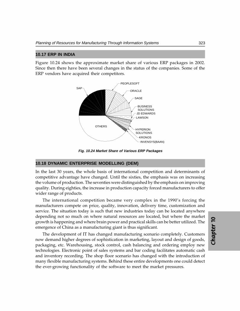
Ch
ap
ter
1C
ha
pte
r 1
Ch
ap
ter
1C
ha
pte
r 1
Ch
ap
ter
1 0000 0
323Planning of Resources for Manufacturing Through Information Systems
10.17 ERP IN INDIA
Figure 10.24 shows the approximate market share of various ERP packages in 2002.Since then there have been several changes in the status of the companies. Some of theERP vendors have acquired their competitors.
SAP
PEOPLESOFT
ORACLE
SAGE
BUSINESSSOLUTIONS
JD EDWARDS
LAWSON
HYPERIONSOLUTIONS
KRONOS
INVENSYS(BAAN)
OTHERS
Fig. 10.24 Market Share of Various ERP Packages
10.18 DYNAMIC ENTERPRISE MODELLING (DEM)
In the last 30 years, the whole basis of international competition and determinants ofcompetitive advantage have changed. Until the sixties, the emphasis was on increasingthe volume of production. The seventies were distinguished by the emphasis on improvingquality. During eighties, the increase in production capacity forced manufacturers to offerwider range of products.
The international competition became very complex in the 1990’s forcing themanufacturers compete on price, quality, innovation, delivery time, customization andservice. The situation today is such that new industries today can be located anywheredepending not so much on where natural resources are located, but where the marketgrowth is happening and where brain power and practical skills can be better utilized. Theemergence of China as a manufacturing giant is thus significant.
The development of IT has changed manufacturing scenario completely. Customersnow demand higher degrees of sophistication in marketing, layout and design of goods,packaging, etc. Warehousing, stock control, cash balancing and ordering employ newtechnologies. Electronic point of sales systems and bar coding facilitates automatic cashand inventory recording. The shop floor scenario has changed with the introduction ofmany flexible manufacturing systems. Behind these entire developments one could detectthe ever-growing functionality of the software to meet the market pressures.
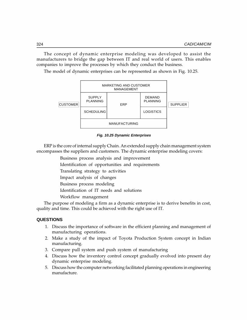
324 CAD/CAM/CIM
The concept of dynamic enterprise modeling was developed to assist themanufacturers to bridge the gap between IT and real world of users. This enablescompanies to improve the processes by which they conduct the business.
The model of dynamic enterprises can be represented as shown in Fig. 10.25.
MARKETING AND CUSTOMERMANAGEMENT
SUPPLYPLANNING
SCHEDULING
DEMANDPLANNING
LOGISTICS
ERP
MANUFACTURING
SUPPLIERCUSTOMER
Fig. 10.25 Dynamic Enterprises
ERP is the core of internal supply Chain. An extended supply chain management systemencompasses the suppliers and customers. The dynamic enterprise modeling covers:
Business process analysis and improvementIdentification of opportunities and requirementsTranslating strategy to activitiesImpact analysis of changesBusiness process modelingIdentification of IT needs and solutionsWorkflow management
The purpose of modeling a firm as a dynamic enterprise is to derive benefits in cost,quality and time. This could be achieved with the right use of IT.
QUESTIONS
1. Discuss the importance of software in the efficient planning and management ofmanufacturing operations.
2. Make a study of the impact of Toyota Production System concept in Indianmanufacturing.
3. Compare pull system and push system of manufacturing4. Discuss how the inventory control concept gradually evolved into present day
dynamic enterprise modeling.5. Discuss how the computer networking facilitated planning operations in engineering
manufacture.
Ch
ap
ter
1C
ha
pte
r 1
Ch
ap
ter
1C
ha
pte
r 1
Ch
ap
ter
1 0000 0
325Planning of Resources for Manufacturing Through Information Systems
6. Describe the major modules of MRP software.7. Why is master schedule important? How does master schedule accommodate
flexibility in manufacturing?8. What are the important sub-modules of a materials requirements planning software?9. What is the significance of capacity requirements planning in the context of
globalization and outsourcing?10. How does shop floor monitoring help in meeting delivery schedules?11. Discuss the inventory management vis-à-vis just in time manufacture.12. Discuss the various modules of purchase management software.13. What is the significance of bill of materials?14. What are the different financial and accounting modules of the manufacturing
information systems?15. Why is enterprise resource planning a holistic approach to manufacturing planning?16. Discuss the scenario of implementation of ERP in Indian manufacturing industries.17. What is meant by a virtual enterprise?

This pageintentionally left
blank
�������������
���������
��� ���
One of the major developments that led to CIM was the introduction of computer control ofmanufacturing equipment and operations. Till the advent of microprocessors and personalcomputers, manufacturing automation was mainly through the so-called hard automationthrough hydraulic, pneumatic or electric methods. Programmable logic controllers (PLC)have now become a very convenient tool for flexible automation. PLC’s are widely used inpneumatic, hydraulic, electric, and electronic automation. CNC machine tools, robots, transfermachines, industrial drives etc. use PLC’s. This chapter introduces the readers to theconcepts of low cost automation as well as automation using PLC’s through simpleapplication circuits.
11.1 INTRODUCTION
Apart from the soft data processing aspects of automation like what was discussed inchapter 10, manufacturing involve machinery and equipment to shape raw materials toparts of desired geometry. Manufacturing processes like casting, welding, forming of sheetmetals and tubes, extrusion, injection molding, spinning, drawing, forging, rolling, cutting,machining, lithography, assembly etc involve different kinds of machinery and equipment.Automation involves not only carrying out the manufacturing process without humanintervention but also many connected operations like stock feeding, proper sequencing ofvarious steps involved in manufacturing, removal of the processed part from the machineor equipment, measurement of the completed part and the removal of swarf and lubricants.For example, in a pressure die casting operation, the molding machine may be hydraulicallyoperated while the molten metal may be automatically transferred from the melting furnaceto the injection chamber. The cast part is automatically picked up after the separation ofthe dies and the parts are cooled and trimmed. Automation is employed to lubricate thedies, cool the dies after part removal etc. Sensors are employed to measure injection speed,shot rod position, hydraulic pressure and other data required to adjust process parametersnot only to ensure castings of consistent quality, shot after shot but also to collectperformance data for statistical analysis for quality assurance purposes as well as futureprocess improvement.
328 CAD/CAM/CIM
Similarly, if one considers the welding operation, welding operations like spot weldingcould be easily automated. In arc welding, the extent of automation is such that the entirewelding activity including electrode feeding, manipulating the work piece, seam trackingetc requires hardly any human intervention.
Manufacturing automation is not limited to metal processing alone. Textiles,semiconductors, chemicals, plastics processing etc today employ very high level ofautomation, lending themselves to integration leading to a CIM system. This chapter andas many of the subsequent chapters are devoted to automation of hardware.
Mechanization preceded automation in manufacturing. Mechanization involvesproviding human operators with machinery to assist them with the physical requirementsof the work. For example, a chip conveyor eliminates the need for operator to remove thechips from the cutting zone in lathe operations. A hydraulic chuck facilitates quick andeasy clamping of work pieces. An automation system eliminates the need for human sensoryinputs and decision making and makes the manufacturing system autonomous.
Semiautomatic and automatic machines were introduced in the early stages ofmanufacturing. Mechanical control by cams was widely employed before the advent ofelectrical control using limit switches and plug board control. Hydraulic tracer controlwas also popular in machining. The advent of the computer era introduced several typesof automation systems one after another. Information input by punched cards was followedby punched tape. Sophisticated data acquisition systems facilitated the automation ofprocess control systems. Transfer lines using a combination of mechanical, electrical,pneumatic and hydraulic automation was introduced by automobile industry. Thedevelopments in semiconductor industry and entertainment electronic industrynecessitated sophisticated automation equipment and robots. Another compelling reasonfor automation is the need for maintenance of consistent quality as human operators aresubject to fatigue, which reduces their concentration, which often has an adverse effect onquality. Automation also increases productivity.
11. 2 TYPES OF AUTOMATION SYSTEMS
Automation systems can be classified into three major types:
i. Pneumatic automationii. Hydraulic automation
iii. Automation systems using programmable logic controllers, which involvecombinations of the above.
These are briefly discussed in the subsequent sections.
11.2.1 PNEUMATIC SYSTEMSMany low cost automation systems are based on air-operated devices. Most of themanufacturing shops will have pressurized air supply for clamping, cleaning etc. This
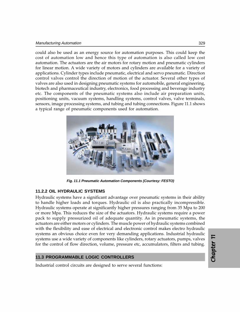
Ch
ap
ter
1C
ha
pte
r 1
Ch
ap
ter
1C
ha
pte
r 1
Ch
ap
ter
1 1111 1
329Manufacturing Automation
could also be used as an energy source for automation purposes. This could keep thecost of automation low and hence this type of automation is also called low costautomation. The actuators are the air motors for rotary motion and pneumatic cylindersfor linear motion. A wide variety of motors and cylinders are available for a variety ofapplications. Cylinder types include pneumatic, electrical and servo pneumatic. Directioncontrol valves control the direction of motion of the actuator. Several other types ofvalves are also used in designing pneumatic systems for automobile, general engineering,biotech and pharmaceutical industry, electronics, food processing and beverage industryetc. The components of the pneumatic systems also include air preparation units,positioning units, vacuum systems, handling systems, control valves, valve terminals,sensors, image processing systems, and tubing and tubing connections. Figure 11.1 showsa typical range of pneumatic components used for automation.
Fig. 11.1 Pneumatic Automation Components (Courtesy: FESTO)
11.2.2 OIL HYDRAULIC SYSTEMSHydraulic systems have a significant advantage over pneumatic systems in their abilityto handle higher loads and torques. Hydraulic oil is also practically incompressible.Hydraulic systems operate at significantly higher pressures ranging from 35 Mpa to 200or more Mpa. This reduces the size of the actuators. Hydraulic systems require a powerpack to supply pressurized oil of adequate quantity. As in pneumatic systems, theactuators are either motors or cylinders. The muscle power of hydraulic systems combinedwith the flexibility and ease of electrical and electronic control makes electro hydraulicsystems an obvious choice even for very demanding applications. Industrial hydraulicsystems use a wide variety of components like cylinders, rotary actuators, pumps, valvesfor the control of flow direction, volume, pressure etc, accumulators, filters and tubing.
11.3 PROGRAMMABLE LOGIC CONTROLLERS
Industrial control circuits are designed to serve several functions:
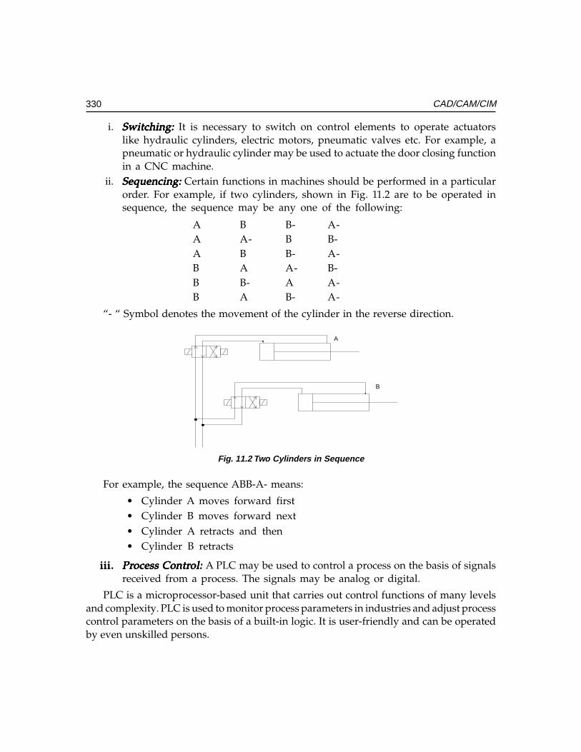
330 CAD/CAM/CIM
i. Switching:Switching:Switching:Switching:Switching: It is necessary to switch on control elements to operate actuatorslike hydraulic cylinders, electric motors, pneumatic valves etc. For example, apneumatic or hydraulic cylinder may be used to actuate the door closing functionin a CNC machine.
ii. Sequencing:Sequencing:Sequencing:Sequencing:Sequencing: Certain functions in machines should be performed in a particularorder. For example, if two cylinders, shown in Fig. 11.2 are to be operated insequence, the sequence may be any one of the following:
A B B- A-A A- B B-A B B- A-B A A- B-B B- A A-B A B- A-
“- “ Symbol denotes the movement of the cylinder in the reverse direction.
A
B
Fig. 11.2 Two Cylinders in Sequence
For example, the sequence ABB-A- means:
• Cylinder A moves forward first• Cylinder B moves forward next• Cylinder A retracts and then• Cylinder B retracts
iii.iii.iii.iii.iii. PrPrPrPrProcess Controcess Controcess Controcess Controcess Control: ol: ol: ol: ol: A PLC may be used to control a process on the basis of signalsreceived from a process. The signals may be analog or digital.
PLC is a microprocessor-based unit that carries out control functions of many levelsand complexity. PLC is used to monitor process parameters in industries and adjust processcontrol parameters on the basis of a built-in logic. It is user-friendly and can be operatedby even unskilled persons.
Ch
ap
ter
1C
ha
pte
r 1
Ch
ap
ter
1C
ha
pte
r 1
Ch
ap
ter
1 1111 1
331Manufacturing Automation
TTTTTypical PLC applications arypical PLC applications arypical PLC applications arypical PLC applications arypical PLC applications are listed below:e listed below:e listed below:e listed below:e listed below:
(a) Switching functions in a CNC machine tool like spindle motor on/off, coolantmotor on/off, chuck opening and closing, tailstock forward/reverse, door close/open, guard open/close, pallet change etc.
(b) Operation of lifts in buildings.(c) Control of electric motors in industrial drives.(d) Transfer machine control.(e) Heating control in process industries.(f) Control of traffic signals.(g) Safety control of presses.(h) Robot control.(i) Home and medical equipment.
PLC is widely used because of several of its advantages, some of which are describedin the following sections:
(i) Flexibility:Flexibility:Flexibility:Flexibility:Flexibility: A PLC can be used for controlling one machine or a group ofmachines. A PLC program can be altered easily through a keyboard sequenceso that the machine functions can be modified at the will of the designerswithout incurring additional cost of hardware or scrapping existing hardware.
(ii) Low cost:Low cost:Low cost:Low cost:Low cost: Technological developments in microelectronics technology havereduced the cost of PLC’s considerably.
(iii) Speed of operation: Speed of operation: Speed of operation: Speed of operation: Speed of operation: PLC’s operate faster than relays.(iv) Security: Security: Security: Security: Security: A PLC program cannot be altered without unlocking the program.(v) Reprogramming: Reprogramming: Reprogramming: Reprogramming: Reprogramming: In the case of transfer machines the modifications in the control
circuit can be carried out by simple reprogramming so that same hardware canbe used for a new sequence.
(vi) Modularity:Modularity:Modularity:Modularity:Modularity: PLC’s can be assembled in a modular fashion. The designer can addmodules depending upon his requirement of the number of inputs and outputs.
(vii) Analog and digital inputs:Analog and digital inputs:Analog and digital inputs:Analog and digital inputs:Analog and digital inputs: PLC can input/output both analog and digital signals.(viii) Correction of errors: Correction of errors: Correction of errors: Correction of errors: Correction of errors: Efficient debugging procedure enables easy error correction.
(ix) Off-line programming:Off-line programming:Off-line programming:Off-line programming:Off-line programming: PLC program can be designed off-line and tested beforeimplementation.
(x) Boolean programming: Boolean programming: Boolean programming: Boolean programming: Boolean programming: PLC programming can be carried out using a ladderdiagram by an experienced technician.
(xi) Documentation: Documentation: Documentation: Documentation: Documentation: PLC programming devices can generate a printout as soon asthe ladder diagram is completed. This avoids the need for separate documentationefforts.
(xii) Reliability:Reliability:Reliability:Reliability:Reliability: Since PLC is a solid-state device the reliability is very high.(xiii) Maintainability: Maintainability: Maintainability: Maintainability: Maintainability: The modular nature of the PLC design makes maintenance easy.
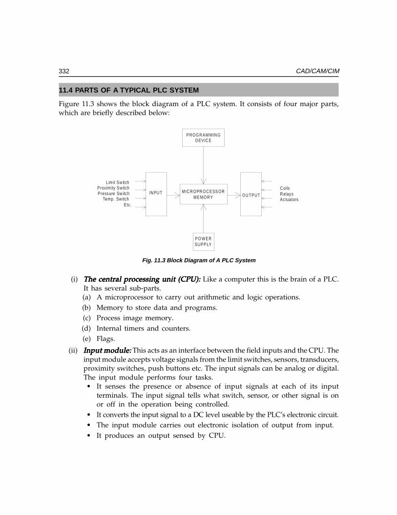
332 CAD/CAM/CIM
11.4 PARTS OF A TYPICAL PLC SYSTEM
Figure 11.3 shows the block diagram of a PLC system. It consists of four major parts,which are briefly described below:
Fig. 11.3 Block Diagram of A PLC System
(i) The central processing unit (CPU):The central processing unit (CPU):The central processing unit (CPU):The central processing unit (CPU):The central processing unit (CPU): Like a computer this is the brain of a PLC.It has several sub-parts.(a) A microprocessor to carry out arithmetic and logic operations.(b) Memory to store data and programs.(c) Process image memory.(d) Internal timers and counters.(e) Flags.
(ii) Input module:Input module:Input module:Input module:Input module: This acts as an interface between the field inputs and the CPU. Theinput module accepts voltage signals from the limit switches, sensors, transducers,proximity switches, push buttons etc. The input signals can be analog or digital.The input module performs four tasks.• It senses the presence or absence of input signals at each of its input
terminals. The input signal tells what switch, sensor, or other signal is onor off in the operation being controlled.
• It converts the input signal to a DC level useable by the PLC’s electronic circuit.• The input module carries out electronic isolation of output from input.• It produces an output sensed by CPU.
Lim it Sw itchProxim ity SwitchPressure Sw itch
Temp. Sw itchEtc .
PROGR AM MIN GD EVIC E
MIC R O PR O C ESS O RME MORY
PO W ERSUPP LY
OU TPUT
C oilsR elaysAc tuators
IN PU T
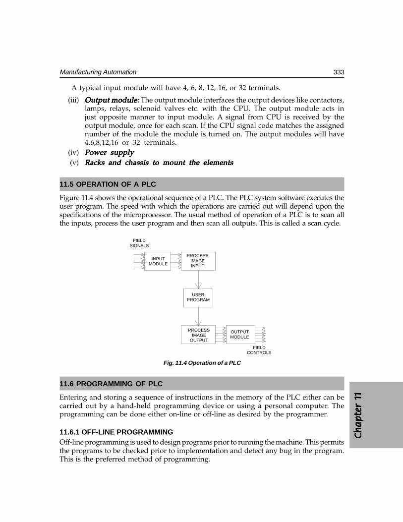
Ch
ap
ter
1C
ha
pte
r 1
Ch
ap
ter
1C
ha
pte
r 1
Ch
ap
ter
1 1111 1
333Manufacturing Automation
A typical input module will have 4, 6, 8, 12, 16, or 32 terminals.
(iii) Output module: Output module: Output module: Output module: Output module: The output module interfaces the output devices like contactors,lamps, relays, solenoid valves etc. with the CPU. The output module acts injust opposite manner to input module. A signal from CPU is received by theoutput module, once for each scan. If the CPU signal code matches the assignednumber of the module the module is turned on. The output modules will have4,6,8,12,16 or 32 terminals.
(iv) Power supplyPower supplyPower supplyPower supplyPower supply(v) Racks and chassis to mount the elementsRacks and chassis to mount the elementsRacks and chassis to mount the elementsRacks and chassis to mount the elementsRacks and chassis to mount the elements
11.5 OPERATION OF A PLC
Figure 11.4 shows the operational sequence of a PLC. The PLC system software executes theuser program. The speed with which the operations are carried out will depend upon thespecifications of the microprocessor. The usual method of operation of a PLC is to scan allthe inputs, process the user program and then scan all outputs. This is called a scan cycle.
PROCESSIMAGE
OUTPUT
PROCESSIMAGEINPUT
USERPROGRAM
OUTPUTMODULE
INPUTMODULE
FIELDSIGNALS
FIELDCONTROLS
Fig. 11.4 Operation of a PLC
11.6 PROGRAMMING OF PLC
Entering and storing a sequence of instructions in the memory of the PLC either can becarried out by a hand-held programming device or using a personal computer. Theprogramming can be done either on-line or off-line as desired by the programmer.
11.6.1 OFF-LINE PROGRAMMINGOff-line programming is used to design programs prior to running the machine. This permitsthe programs to be checked prior to implementation and detect any bug in the program.This is the preferred method of programming.
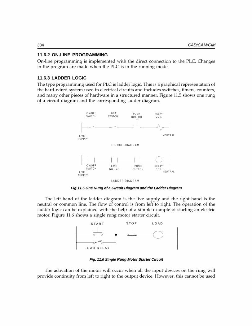
334 CAD/CAM/CIM
11.6.2 ON-LINE PROGRAMMINGOn-line programming is implemented with the direct connection to the PLC. Changesin the program are made when the PLC is in the running mode.
11.6.3 LADDER LOGICThe type programming used for PLC is ladder logic. This is a graphical representation ofthe hard-wired system used in electrical circuits and includes switches, timers, counters,and many other pieces of hardware in a structured manner. Figure 11.5 shows one rungof a circuit diagram and the corresponding ladder diagram.
O N /OF FSW ITC H
LIM ITSW ITC H
PU S HBU TTO N
R ELAYC O IL
O N /OF FSW ITC H
LIM ITSW ITC H
PU S HBU TTO N
R ELAYC O IL
L IV ESU P PLY
N EU TR AL
LIV ESU P PLY
N EU TR AL
C IR C U IT D IA G R A M
L A D D E R D IA G R A M
Fig.11.5 One Rung of a Circuit Diagram and the Ladder Diagram
The left hand of the ladder diagram is the live supply and the right hand is theneutral or common line. The flow of control is from left to right. The operation of theladder logic can be explained with the help of a simple example of starting an electricmotor. Figure 11.6 shows a single rung motor starter circuit.
S T A R T S T O P L O A D
L O A D R E L A Y
Fig. 11.6 Single Rung Motor Starter Circuit
The activation of the motor will occur when all the input devices on the rung willprovide continuity from left to right to the output device. However, this cannot be used
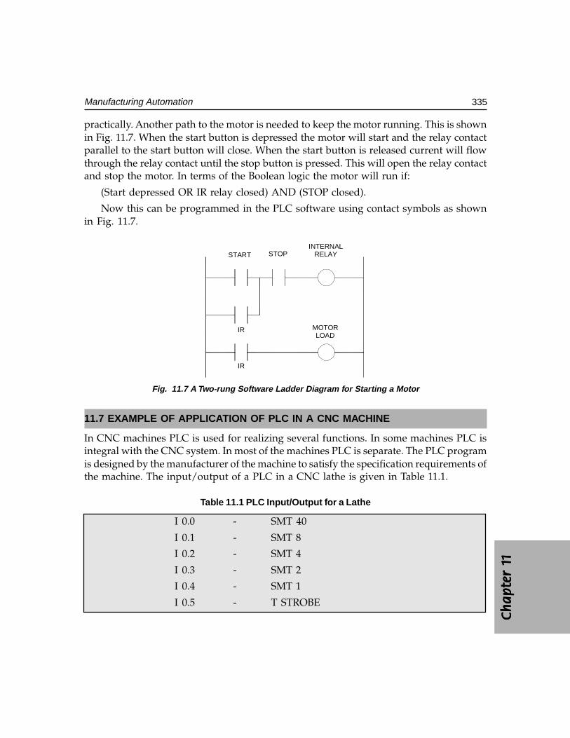
Ch
ap
ter
1C
ha
pte
r 1
Ch
ap
ter
1C
ha
pte
r 1
Ch
ap
ter
1 1111 1
335Manufacturing Automation
practically. Another path to the motor is needed to keep the motor running. This is shownin Fig. 11.7. When the start button is depressed the motor will start and the relay contactparallel to the start button will close. When the start button is released current will flowthrough the relay contact until the stop button is pressed. This will open the relay contactand stop the motor. In terms of the Boolean logic the motor will run if:
(Start depressed OR IR relay closed) AND (STOP closed).
Now this can be programmed in the PLC software using contact symbols as shownin Fig. 11.7.
START STOPINTERNAL
RELAY
IR
IR
MOTORLOAD
Fig. 11.7 A Two-rung Software Ladder Diagram for Starting a Motor
11.7 EXAMPLE OF APPLICATION OF PLC IN A CNC MACHINE
In CNC machines PLC is used for realizing several functions. In some machines PLC isintegral with the CNC system. In most of the machines PLC is separate. The PLC programis designed by the manufacturer of the machine to satisfy the specification requirements ofthe machine. The input/output of a PLC in a CNC lathe is given in Table 11.1.
Table 11.1 PLC Input/Output for a Lathe
I 0.0 - SMT 40
I 0.1 - SMT 8
I 0.2 - SMT 4
I 0.3 - SMT 2
I 0.4 - SMT 1
I 0.5 - T STROBE
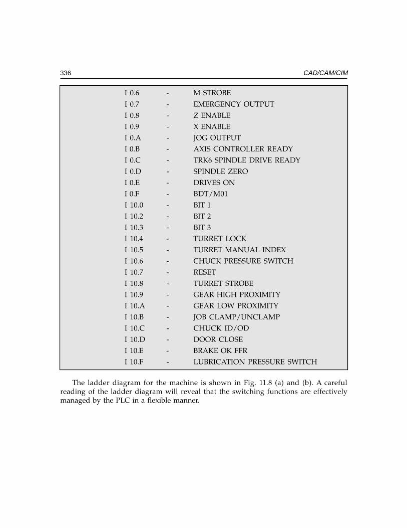
336 CAD/CAM/CIM
I 0.6 - M STROBE
I 0.7 - EMERGENCY OUTPUT
I 0.8 - Z ENABLE
I 0.9 - X ENABLE
I 0.A - JOG OUTPUT
I 0.B - AXIS CONTROLLER READY
I 0.C - TRK6 SPINDLE DRIVE READY
I 0.D - SPINDLE ZERO
I 0.E - DRIVES ON
I 0.F - BDT/M01
I 10.0 - BIT 1
I 10.2 - BIT 2
I 10.3 - BIT 3
I 10.4 - TURRET LOCK
I 10.5 - TURRET MANUAL INDEX
I 10.6 - CHUCK PRESSURE SWITCH
I 10.7 - RESET
I 10.8 - TURRET STROBE
I 10.9 - GEAR HIGH PROXIMITY
I 10.A - GEAR LOW PROXIMITY
I 10.B - JOB CLAMP/UNCLAMP
I 10.C - CHUCK ID/OD
I 10.D - DOOR CLOSE
I 10.E - BRAKE OK FFR
I 10.F - LUBRICATION PRESSURE SWITCH
The ladder diagram for the machine is shown in Fig. 11.8 (a) and (b). A carefulreading of the ladder diagram will reveal that the switching functions are effectivelymanaged by the PLC in a flexible manner.
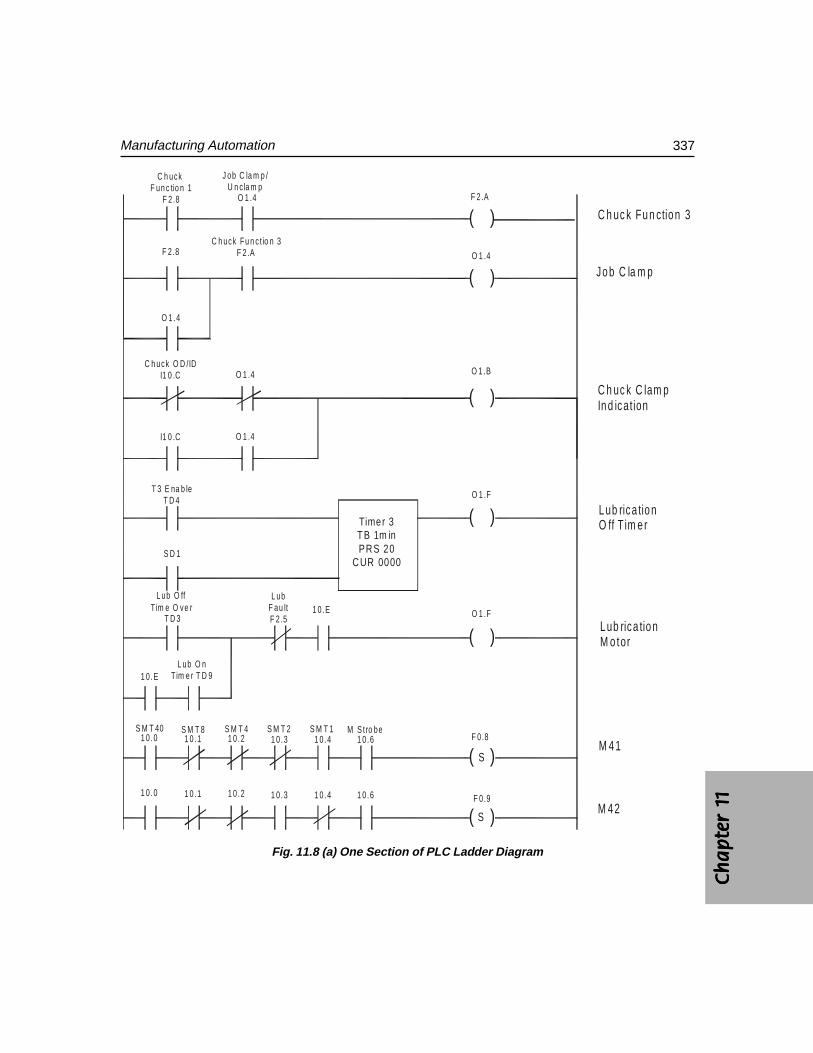
Ch
ap
ter
1C
ha
pte
r 1
Ch
ap
ter
1C
ha
pte
r 1
Ch
ap
ter
1 1111 1
337Manufacturing Automation
( )
( )
( )
( )
( )
( )
( )
Timer 3TB 1m inPRS 20
CUR 0000S D 1
L ub O ffT im e O ve r
T D 3
1 0.EL ub O n
Tim e r T D 9
L ubF au ltF 2 .5
1 0 .E
S M T 40 S M T 8 S M T 4 S M T 21 0.0 1 0 .1 1 0 .2 1 0 .3
S M T 1 M S t ro be1 0 .4 1 0 .6
1 0 .0 1 0 .1 1 0 .2 1 0 .3 1 0 .4 1 0 .6
C h uck F un c tio n 1
F 2 .8
J ob C la m p /U n cla m p
C h uck Fu n c t io n 3F 2 .AF 2.8
O 1 .4
O 1 .4
C h uck O D /IDI1 0 .C O 1 .4
I1 0 .C O 1 .4
T 3 E na b leT D 4
F 2.A
O 1 .4
O 1 .B
O 1 .F
F 0 .8
F 0 .9
S
S
O 1 .F
C h uc k Fu n ctio n 3
Jo b C la m p
C h uc k C lam pIn d ication
L ub rica tio nO ff T im e r
L ub rica tio nM o tor
M 4 1
M 4 2
Fig. 11.8 (a) One Section of PLC Ladder Diagram
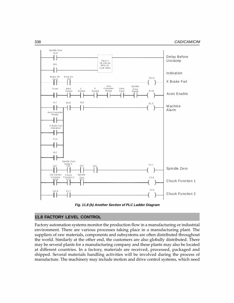
338 CAD/CAM/CIM
Fig. 11.8 (b) Another Section of PLC Ladder Diagram
11.8 FACTORY LEVEL CONTROL
Factory automation systems monitor the production flow in a manufacturing or industrialenvironment. There are various processes taking place in a manufacturing plant. Thesuppliers of raw materials, components and subsystems are often distributed throughoutthe world. Similarly at the other end, the customers are also globally distributed. Theremay be several plants for a manufacturing company and these plants may also be locatedat different countries. In a factory, materials are received, processed, packaged andshipped. Several materials handling activities will be involved during the process ofmanufacture. The machinery may include motion and drive control systems, which need
( )
( )
( )
( )
( )
( )
Sp ind le Z ero1 0. D
S0 1
Tim e r 1T B 1 00 ms
PR S 1 0C UR 00 0 0
Brak e O k D riv e O nI1 0 .E I0 .E
Tu rre t EM GO u tp ut
Z En a b le
XEn a b le
Ax isC o nt rolle r
R e ad yL ub eF a u lt
I0 .E
Sp ind leD riv e
R e ad y
I0 .7 S0 .E
Ax is C on t ro lle rR e ad y
X B ra k e Fa ilIn d ic ati o n
F 2 .5
I0 .C
Sp ind le Z eroD e la y 2
I0 .E T D1 I0 .C I0 .D
J ob C la m p /U n c la m p
C h uc k F u n c tio n 2
Sp ind le Z e ro
I1 0 .B F 2 .9 F 2 .7
I1 0 .B F 2 .7
0 11 .0
0 1. B
0 1. C
F 2 .7
F 2 .8
F 2 .9
Delay BeforeUnc la mp
X Bra ke Fa il
In dicat ion
Axes Ena ble
M achin e Ala rm
Sp in dle Ze ro
Chuck Fu nc tio n 1
Chuck Fu nc tio n 2
Ch
ap
ter
1C
ha
pte
r 1
Ch
ap
ter
1C
ha
pte
r 1
Ch
ap
ter
1 1111 1
339Manufacturing Automation
continuous control and monitoring. The manufacturing or process operations have tobe monitored using appropriate sensors located in the machinery or shop floor. In addition,there will be several utilities connected with the plant, which require monitoring andcontrol. It is desirable that these are controlled from a single integrated system. It is alsonecessary that such systems should be scalable to accommodate future expansion.
Many companies like Siemens, Rockwell, and Honeywell etc. provide such integratedautomation systems. The Rockwell Automation system is mentioned here as the exampleof integrated architecture. This uses a combination of enabling technologies like Logixcontrol platform, NetLinx open network architecture, View Visualization Platform andFactoryTalk data and information services. Brief descriptions of each of the above aregiven below, courtesy Rockwell Automation.
The Logix control platform enables the user to choose the most effective controllerfor a given application. These are programmed through a single software package.Programming can be done using any of the following:
• Ladder Diagram• Function Block• Sequential Function Chart• Structured Text Language
The use of the Logix controller results in significant reduction in design, hardwareand programming costs.
Netlinx open networks provide a network infrastructure information flow. Theseshare a common protocol which enables seamless flow of information from the deviceon the plant floor to the enterprise system without additional programming. Reducedprogramming, increase in flexibility, reduction in installation cost and increasedproductivity are the benefits of this approach.
View Visualization platform is a unified suite of operator interface and supervisorylevel monitoring solutions, that share the same development software. The advantages ofthis system are faster development and implementation, flexibility and lower cost ofownership.
FactoryTalk is a suite of services embedded in integrated architecture componentsthat simplifies data production, movement and use. FactoryTalk services give the user atag only once and reuse it throughout the entire control system.
The advantages of such systems are:
• Improvement in response time and decision making• Reduced maintenance cost and downtime• Scalability to ensure future growth• Increased operator response time• Reduced implementation time• Reduced costs• Availability of information across the enterprise
340 CAD/CAM/CIM
QUESTIONS
1. Study the automation systems used in a manufacturing company.2. Discuss the importance of low cost automation in improving productivity in
small and medium industries.3. Design a simple low cost automation system for automating turning and
cutting off operations in a centre lathe.4. Compare hydraulic and pneumatic automation systems.5. Discuss the need for flexibility in automated manufacturing systems.6. What are the essential elements of a PLC system?7. Discuss with an example, the principle of operation of a programmable logic
controller.8. What are the roles of a PLC in a CNC machine?9. Discuss the details of any one of the integrated plant automation software and
hardware products.
����������������
��� ��
12.1 INTRODUCTION
After the Second World War, there was a big spurt in the design and development ofaerospace products like satellites, launch vehicles, civil and military aircraft etc. Thehydraulic copying and electrical program controlled machines used at that time could notmeet the manufacturing challenges posed by the complex aerospace designs. Themanufacturing engineers were therefore looking for a better way of automating themachining operations. Numerical control (NC) was developed in early 50’s to meet thecritical requirements of aerospace Industry. Many components used in aircraft and spacevehicles are machined from solid raw materials, often involving removal of considerablestock and requiring several hundred positioning movements of the machine tool slides.Manual operation under these circumstances is not only tedious but also less efficientand unproductive. Often the part after several hours of machining is liable to be rejecteddue to machining errors.
Digital technology developed for communication purposes became very handy fordesigners of control of machine tools. Since the information required to actuate and controlslides was coded numerically, this technology came to be known as numerical control.
Production equipment with computer numerical control is a major component of CIM.Computer numerically controlled (C N C) Machine Tools paved the way for introducingflexible automation on the shop floor. The technology of computer numerical control istoday applied to a large spectrum of material processing equipment. The developments inCNC have been one of the major factors that have contributed to the evolution of CAD/CAMand subsequently CIM. For manufacturing a component, the CAD/CAM process generates aprogram, which can run on the CNC machine. The fundamentals of numerical control, thetypes of CNC machines and the programming techniques are presented in this chapter. Thefeatures of CAM software and CNC systems are discussed in detail. The integration of CNCmachines in the CIM environment is also dealt with in this chapter.
342 CAD/CAM/CIM
Early numerically controlled machines were fully hardwired machines as the entirecontrol logic was implemented in hardware. This posed several difficulties in theoperation of NC machines apart from serious limitations on reliability of operation. Thedesigners of NC machines achieved a major breakthrough during mid-six tees whenthey could integrate a NC machine tool with a mini-computer. The technology was thenrenamed as computer numerical control. The integration of computers with NC machinetools resulted in the following advantages:
• Increase in the memory for part program processing
• Increase in capacity for storing large part programs
• Easy editing of part programs on the control console
• Realization of control logic through software
• Significant improvement in the reliability of operation of the machines• Integration of N.C. machines in the manufacturing system as a whole.
Further developments in large scale integration resulted in the development ofmicroprocessors around which computers could be designed. This naturally led to thedevelopment of CNC systems based on microprocessors. Today all CNC machines aremicroprocessor based and both NC and CNC mean computer numerical control.
12.2 PRINCIPLE OF OPERATION OF A NUMERICAL CONTROLLED MACHINE
The CNC machine differs from a conventional manual machine in several respects.The principle of operation of a numerical controlled machine can be explained withthe help of Fig. 12.1. The figure shows a vertical milling machine. For carrying outan operation like end milling the spindle head is to be positioned in Z- axis and thetable in X and Y coordinate axes. The feed movement is to be realized by the individualor simultaneous movement of X and Y axes. Thus the milling machine requires threeslide movements, which are usually referred as axes feed drives. A special feature of aCNC machine is that a separate motor called a servomotor individually drives eachaxis. AC servomotors are the preferred choice for this purpose today. DC servomotorswere widely used earlier. The slides are driven by the servomotors through re-circulating ball screw and nut assemblies. The use of re-circulating ball screw reducesfriction, backlash and wear. The low friction reduces the torque required at the motorand the lost motion through torsional deflection of the screw. The use of ball screwsalso improves the dynamic response of the system. In some modern designs, particularlyin the case of high-speed machines, linear motors are used in the place of servomotorball screw combination.
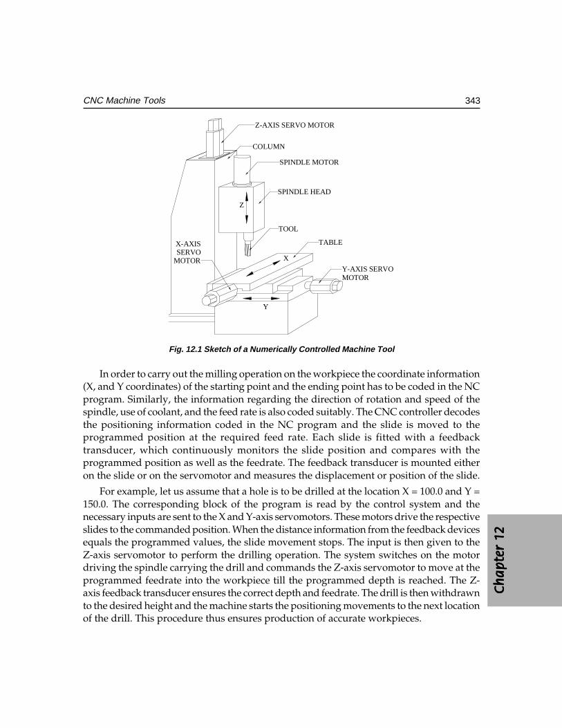
Ch
ap
ter
12C
ha
pte
r 12
Ch
ap
ter
12C
ha
pte
r 12
Ch
ap
ter
12
343CNC Machine Tools
Z-AXIS SERVO MOTOR
COLUMN
SPINDLE MOTOR
SPINDLE HEAD
TOOL
TABLE
Y-AXIS SERVOMOTOR
X-AXISSERVO
MOTOR
Z
X
Y
Fig. 12.1 Sketch of a Numerically Controlled Machine Tool
In order to carry out the milling operation on the workpiece the coordinate information(X, and Y coordinates) of the starting point and the ending point has to be coded in the NCprogram. Similarly, the information regarding the direction of rotation and speed of thespindle, use of coolant, and the feed rate is also coded suitably. The CNC controller decodesthe positioning information coded in the NC program and the slide is moved to theprogrammed position at the required feed rate. Each slide is fitted with a feedbacktransducer, which continuously monitors the slide position and compares with theprogrammed position as well as the feedrate. The feedback transducer is mounted eitheron the slide or on the servomotor and measures the displacement or position of the slide.
For example, let us assume that a hole is to be drilled at the location X = 100.0 and Y =150.0. The corresponding block of the program is read by the control system and thenecessary inputs are sent to the X and Y-axis servomotors. These motors drive the respectiveslides to the commanded position. When the distance information from the feedback devicesequals the programmed values, the slide movement stops. The input is then given to theZ-axis servomotor to perform the drilling operation. The system switches on the motordriving the spindle carrying the drill and commands the Z-axis servomotor to move at theprogrammed feedrate into the workpiece till the programmed depth is reached. The Z-axis feedback transducer ensures the correct depth and feedrate. The drill is then withdrawnto the desired height and the machine starts the positioning movements to the next locationof the drill. This procedure thus ensures production of accurate workpieces.
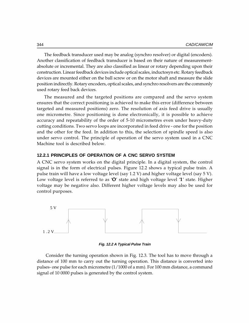
344 CAD/CAM/CIM
The feedback transducer used may be analog (synchro resolver) or digital (encoders).Another classification of feedback transducer is based on their nature of measurement-absolute or incremental. They are also classified as linear or rotary depending upon theirconstruction. Linear feedback devices include optical scales, inductosyn etc. Rotary feedbackdevices are mounted either on the ball screw or on the motor shaft and measure the slideposition indirectly. Rotary encoders, optical scales, and synchro resolvers are the commonlyused rotary feed back devices.
The measured and the targeted positions are compared and the servo systemensures that the correct positioning is achieved to make this error (difference betweentargeted and measured positions) zero. The resolution of axis feed drive is usuallyone micrometre. Since positioning is done electronically, it is possible to achieveaccuracy and repeatability of the order of 5-10 micrometres even under heavy-dutycutting conditions. Two servo loops are incorporated in feed drive - one for the positionand the other for the feed. In addition to this, the selection of spindle speed is alsounder servo control. The principle of operation of the servo system used in a CNCMachine tool is described below.
12.2.1 PRINCIPLES OF OPERATION OF A CNC SERVO SYSTEM
A CNC servo system works on the digital principle. In a digital system, the controlsignal is in the form of electrical pulses. Figure 12.2 shows a typical pulse train. Apulse train will have a low voltage level (say 1.2 V) and higher voltage level (say 5 V).Low voltage level is referred to as ‘OOOOO’ state and high voltage level ‘11111’ state. Highervoltage may be negative also. Different higher voltage levels may also be used forcontrol purposes.
1 . 2 V
5 V
Fig. 12.2 A Typical Pulse Train
Consider the turning operation shown in Fig. 12.3. The tool has to move through adistance of 100 mm to carry out the turning operation. This distance is converted intopulses- one pulse for each micrometre (1/1000 of a mm). For 100 mm distance, a commandsignal of 10 0000 pulses is generated by the control system.
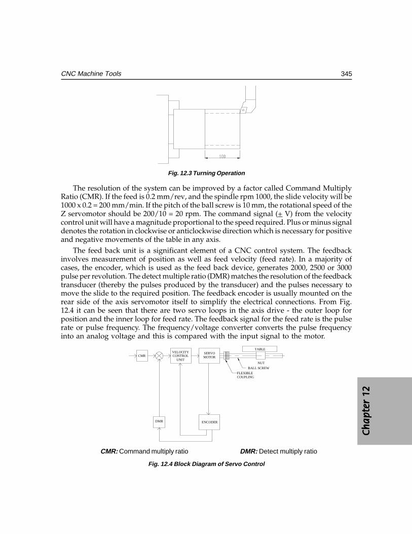
Ch
ap
ter
12C
ha
pte
r 12
Ch
ap
ter
12C
ha
pte
r 12
Ch
ap
ter
12
345CNC Machine Tools
Fig. 12.3 Turning Operation
The resolution of the system can be improved by a factor called Command MultiplyRatio (CMR). If the feed is 0.2 mm/rev, and the spindle rpm 1000, the slide velocity will be1000 x 0.2 = 200 mm/min. If the pitch of the ball screw is 10 mm, the rotational speed of theZ servomotor should be 200/10 = 20 rpm. The command signal (+ V) from the velocitycontrol unit will have a magnitude proportional to the speed required. Plus or minus signaldenotes the rotation in clockwise or anticlockwise direction which is necessary for positiveand negative movements of the table in any axis.
The feed back unit is a significant element of a CNC control system. The feedbackinvolves measurement of position as well as feed velocity (feed rate). In a majority ofcases, the encoder, which is used as the feed back device, generates 2000, 2500 or 3000pulse per revolution. The detect multiple ratio (DMR) matches the resolution of the feedbacktransducer (thereby the pulses produced by the transducer) and the pulses necessary tomove the slide to the required position. The feedback encoder is usually mounted on therear side of the axis servomotor itself to simplify the electrical connections. From Fig.12.4 it can be seen that there are two servo loops in the axis drive - the outer loop forposition and the inner loop for feed rate. The feedback signal for the feed rate is the pulserate or pulse frequency. The frequency/voltage converter converts the pulse frequencyinto an analog voltage and this is compared with the input signal to the motor.
VELOCITYCONTROL
UNIT
SERVOMOTOR
ENCODERDMR
TABLE
BALL SCREW
NUT
FLEXIBLECOUPLING
CMR
CMR: Command multiply ratio DMR: Detect multiply ratio
Fig. 12.4 Block Diagram of Servo Control
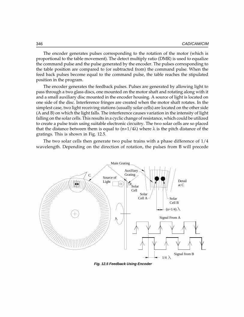
346 CAD/CAM/CIM
The encoder generates pulses corresponding to the rotation of the motor (which isproportional to the table movement). The detect multiply ratio (DMR) is used to equalizethe command pulse and the pulse generated by the encoder. The pulses corresponding tothe table position are compared to (or subtracted from) the command pulse. When thefeed back pulses become equal to the command pulse, the table reaches the stipulatedposition in the program.
The encoder generates the feedback pulses. Pulses are generated by allowing light topass through a two glass discs, one mounted on the motor shaft and rotating along with itand a small auxiliary disc mounted in the encoder housing. A source of light is located onone side of the disc. Interference fringes are created when the motor shaft rotates. In thesimplest case, two light receiving stations (usually solar cells) are located on the other side(A and B) on which the light falls. The interference causes variation in the intensity of lightfalling on the solar cells. This results in a cyclic change of resistance, which could be utilizedto create a pulse train using suitable electronic circuitry. The two solar cells are so placedthat the distance between them is equal to (n+1/4λ) where λ is the pitch distance of thegratings. This is shown in Fig. 12.5.
The two solar cells then generate two pulse trains with a phase difference of 1/4wavelength. Depending on the direction of rotation, the pulses from B will precede
Fig. 12.5 Feedback Using Encoder
SolarCell A Solar
Cell B
(n+1/4)
1/4
C
Detailat C
Source ofLight
SolarCell
Main Grating
AuxiliaryGrating
Signal From A
Signal from B
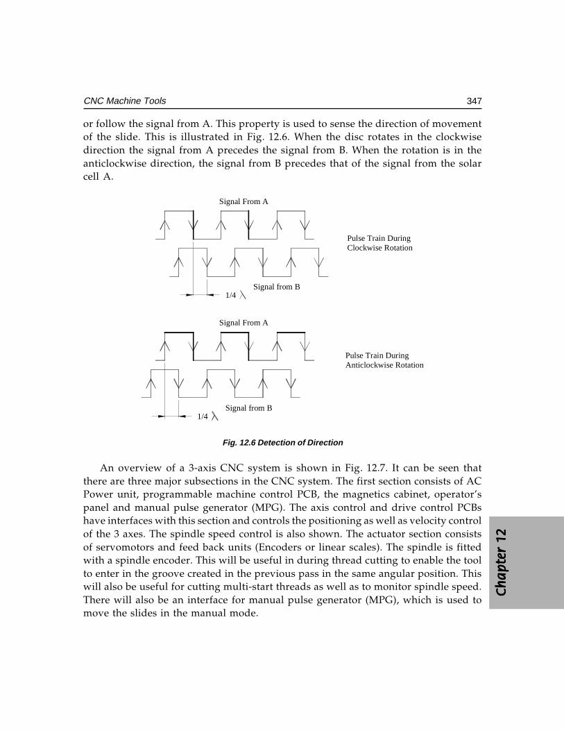
Ch
ap
ter
12C
ha
pte
r 12
Ch
ap
ter
12C
ha
pte
r 12
Ch
ap
ter
12
347CNC Machine Tools
or follow the signal from A. This property is used to sense the direction of movementof the slide. This is illustrated in Fig. 12.6. When the disc rotates in the clockwisedirection the signal from A precedes the signal from B. When the rotation is in theanticlockwise direction, the signal from B precedes that of the signal from the solarcell A.
1/4
Signal From A
Signal from B
Signal From A
Signal from B1/4
Pulse Train DuringClockwise Rotation
Pulse Train DuringAnticlockwise Rotation
Fig. 12.6 Detection of Direction
An overview of a 3-axis CNC system is shown in Fig. 12.7. It can be seen thatthere are three major subsections in the CNC system. The first section consists of ACPower unit, programmable machine control PCB, the magnetics cabinet, operator’spanel and manual pulse generator (MPG). The axis control and drive control PCBshave interfaces with this section and controls the positioning as well as velocity controlof the 3 axes. The spindle speed control is also shown. The actuator section consistsof servomotors and feed back units (Encoders or linear scales). The spindle is fittedwith a spindle encoder. This will be useful in during thread cutting to enable the toolto enter in the groove created in the previous pass in the same angular position. Thiswill also be useful for cutting multi-start threads as well as to monitor spindle speed.There will also be an interface for manual pulse generator (MPG), which is used tomove the slides in the manual mode.
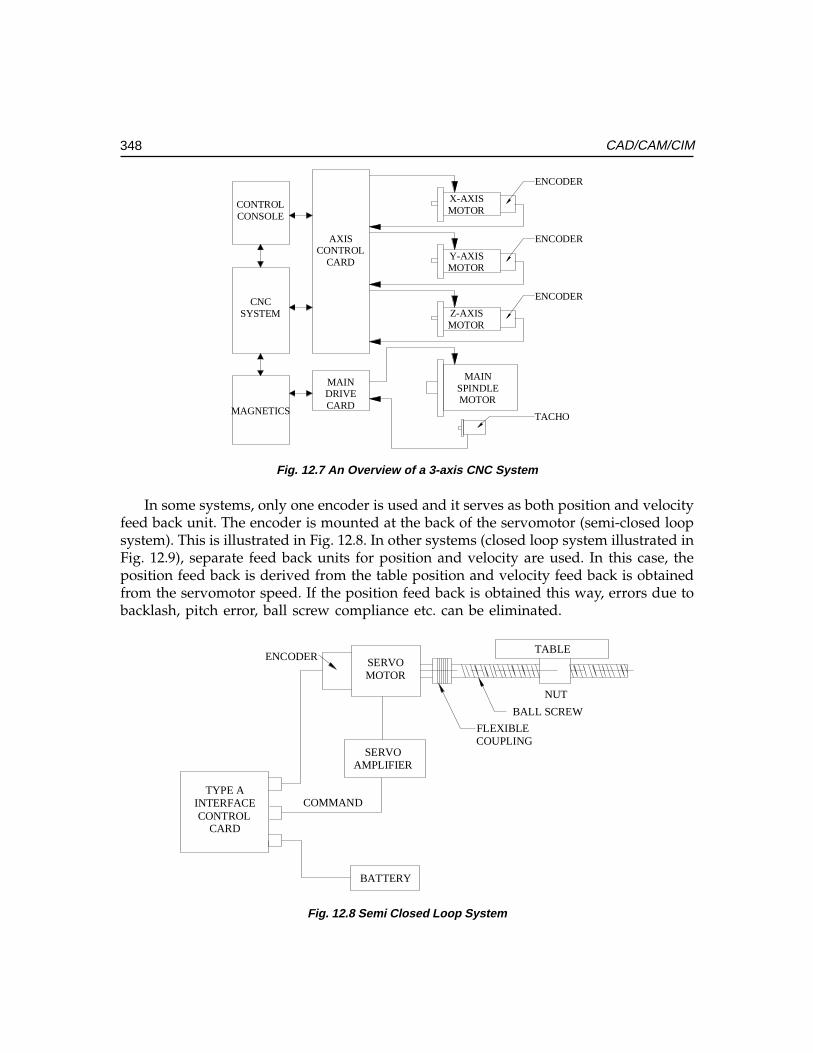
348 CAD/CAM/CIM
CONTROLCONSOLE
CNCSYSTEM
MAGNETICS
AXISCONTROL
CARD
MAINDRIVECARD
X-AXISMOTOR
Y-AXISMOTOR
Z-AXISMOTOR
MAINSPINDLEMOTOR
ENCODER
ENCODER
ENCODER
TACHO
Fig. 12.7 An Overview of a 3-axis CNC System
In some systems, only one encoder is used and it serves as both position and velocityfeed back unit. The encoder is mounted at the back of the servomotor (semi-closed loopsystem). This is illustrated in Fig. 12.8. In other systems (closed loop system illustrated inFig. 12.9), separate feed back units for position and velocity are used. In this case, theposition feed back is derived from the table position and velocity feed back is obtainedfrom the servomotor speed. If the position feed back is obtained this way, errors due tobacklash, pitch error, ball screw compliance etc. can be eliminated.
TABLE
BALL SCREW
NUT
FLEXIBLECOUPLING
TYPE AINTERFACE
CARD
SERVOAMPLIFIER
COMMAND
BATTERY
CONTROL
ENCODER SERVOMOTOR
Fig. 12.8 Semi Closed Loop System
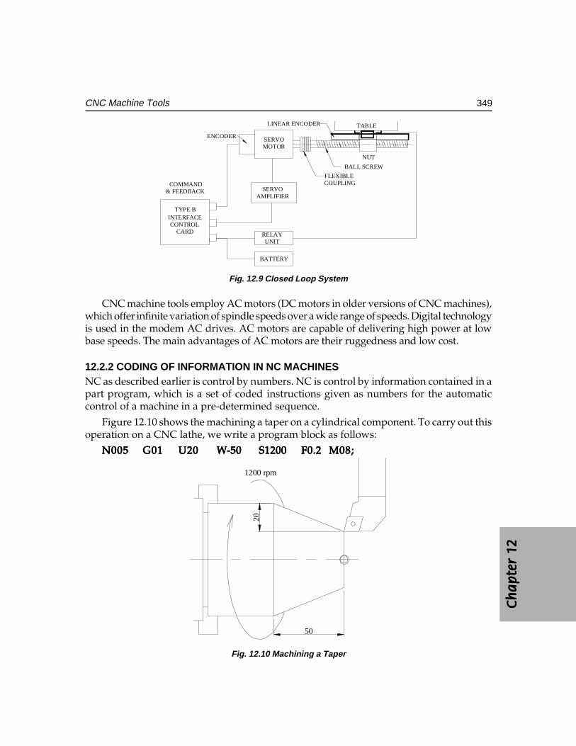
Ch
ap
ter
12C
ha
pte
r 12
Ch
ap
ter
12C
ha
pte
r 12
Ch
ap
ter
12
349CNC Machine Tools
TABLE
BALL SCREW
NUT
FLEXIBLECOUPLING
INTERFACE
CARD
SERVOAMPLIFIER
COMMAND
BATTERY
CONTROL
ENCODER
TYPE B
LINEAR ENCODER
RELAYUNIT
& FEEDBACK
SERVOMOTOR
Fig. 12.9 Closed Loop System
CNC machine tools employ AC motors (DC motors in older versions of CNC machines),which offer infinite variation of spindle speeds over a wide range of speeds. Digital technologyis used in the modem AC drives. AC motors are capable of delivering high power at lowbase speeds. The main advantages of AC motors are their ruggedness and low cost.
12.2.2 CODING OF INFORMATION IN NC MACHINESNC as described earlier is control by numbers. NC is control by information contained in apart program, which is a set of coded instructions given as numbers for the automaticcontrol of a machine in a pre-determined sequence.
Figure 12.10 shows the machining a taper on a cylindrical component. To carry out thisoperation on a CNC lathe, we write a program block as follows:
N005N005N005N005N005 G01G01G01G01G01 U20U20U20U20U20 WWWWW-50-50-50-50-50 S1200 S1200 S1200 S1200 S1200 F0.2F0.2F0.2F0.2F0.2 M08;M08;M08;M08;M08;
1200 rpm
50
20
Fig. 12.10 Machining a Taper
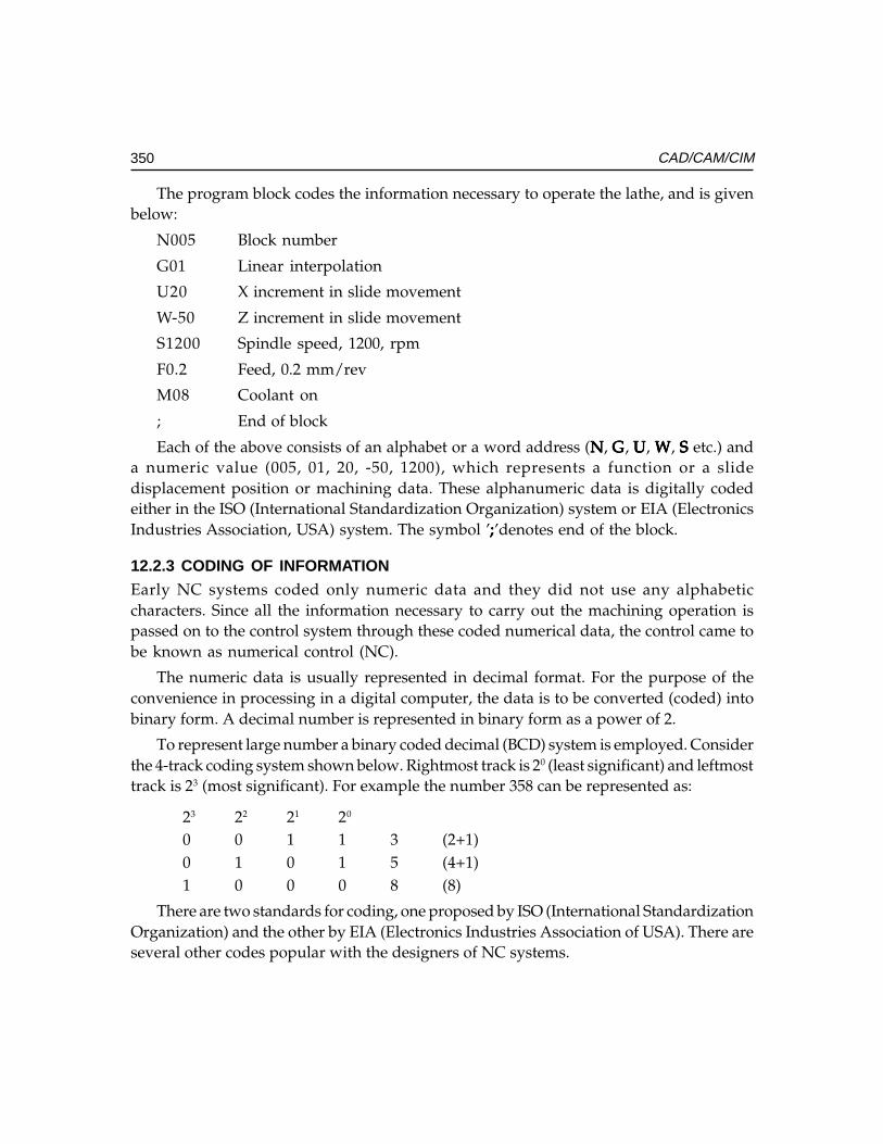
350 CAD/CAM/CIM
The program block codes the information necessary to operate the lathe, and is givenbelow:
N005 Block number
G01 Linear interpolation
U20 X increment in slide movement
W-50 Z increment in slide movement
S1200 Spindle speed, 1200, rpm
F0.2 Feed, 0.2 mm/rev
M08 Coolant on
; End of block
Each of the above consists of an alphabet or a word address (NNNNN, GGGGG, UUUUU, WWWWW, SSSSS etc.) anda numeric value (005, 01, 20, -50, 1200), which represents a function or a slidedisplacement position or machining data. These alphanumeric data is digitally codedeither in the ISO (International Standardization Organization) system or EIA (ElectronicsIndustries Association, USA) system. The symbol ’;;;;;’denotes end of the block.
12.2.3 CODING OF INFORMATIONEarly NC systems coded only numeric data and they did not use any alphabeticcharacters. Since all the information necessary to carry out the machining operation ispassed on to the control system through these coded numerical data, the control came tobe known as numerical control (NC).
The numeric data is usually represented in decimal format. For the purpose of theconvenience in processing in a digital computer, the data is to be converted (coded) intobinary form. A decimal number is represented in binary form as a power of 2.
To represent large number a binary coded decimal (BCD) system is employed. Considerthe 4-track coding system shown below. Rightmost track is 20 (least significant) and leftmosttrack is 23 (most significant). For example the number 358 can be represented as:
23 22 21 20
0 0 1 1 3 (2+1)0 1 0 1 5 (4+1)1 0 0 0 8 (8)
There are two standards for coding, one proposed by ISO (International StandardizationOrganization) and the other by EIA (Electronics Industries Association of USA). There areseveral other codes popular with the designers of NC systems.
Ch
ap
ter
12C
ha
pte
r 12
Ch
ap
ter
12C
ha
pte
r 12
Ch
ap
ter
12
351CNC Machine Tools
12.3 HISTORICAL DEVELOPMENT
As mentioned in the beginning of this chapter, the need for a new technology to controlmachine movement was felt during late 40’s to meet the challenges in the production ofaerospace components. The manufacture of many of these components involves severalthousands of machine movements.
A major contribution to this development was made by John Parsons who developeda technique to machine accurate templates to manufacture helicopter blades. This involvedcalculating 200 points on a curve and drilling them on a precision jig mill. He subsequentlydeveloped in 1948 a 3-D method of machining using ball end mill on a SIP jig bore and aDe Vlieg jig mill. The successive settings of the tool were determined using the IBMpunched card reader. Parsons was later entrusted with the development of a (NC) millingmachine working on the same principle. The U S Air Force was the funding agency forthe NC development. Parsons found that card reader is too slow and approachedMassachusetts Institute of Technology (MIT) to develop a tape reader and power drivefor the proposed machine. The collaboration between Parsons and M I T ran intodifficulties later. U S Air force, then, awarded a contract to M I T. The ServomechanismsLaboratory of M I T developed the first N C Machine in 1952. Giddings and Lewis, GeneralElectric and Bendix are the companies who took interest in developing NC technology,in its early years.
The development of the machine hardware and the programming technique calledAutomatic Positioning of Tools (APT) was undertaken almost simultaneously at MIT.It must also be noted here that another project undertaken at that time at M I T (WhirlWind Project) led to development of Interactive Computer Graphics. This ultimately ledto the development of CAD technology through stages like 2-D drafting, 3-D modeling,surface modeling, solid modeling etc. The project to develop drives resulted in thedevelopment of DC variable speed drives. The first CNC system developed at MIT usedrelays. Subsequent developments in electronics and VLSI design led to the developmentof present generation CNC machines and computer aided manufacturing technology.The efforts to integrate CAD and CAM and later all other activities connected withmanufacture resulted in the development of Computer Integrated Manufacturing. (CIM).It can be said that the path breaking development of John Parsons is the beginning of theCIM technology.
Presently, all the NC machines produced are computer numerical control machines,as the NC system (or CNC system) is designed and built around one or moremicroprocessors. CNC Machine tools now form a major part of output of machine toolsin advanced countries. Table 12.1 gives the status of CNC Machine tool production inIndia in 2002.
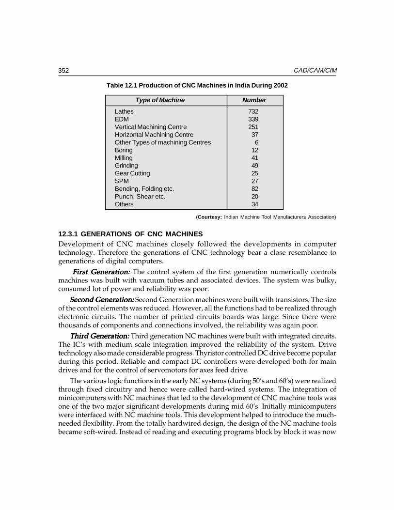
352 CAD/CAM/CIM
Table 12.1 Production of CNC Machines in India During 2002
Type of Machine Number
Lathes 732EDM 339Vertical Machining Centre 251Horizontal Machining Centre 37Other Types of machining Centres 6Boring 12Milling 41Grinding 49Gear Cutting 25SPM 27Bending, Folding etc. 82Punch, Shear etc. 20Others 34
(Courtesy: Indian Machine Tool Manufacturers Association)
12.3.1 GENERATIONS OF CNC MACHINESDevelopment of CNC machines closely followed the developments in computertechnology. Therefore the generations of CNC technology bear a close resemblance togenerations of digital computers.
First Generation:First Generation:First Generation:First Generation:First Generation: The control system of the first generation numerically controlsmachines was built with vacuum tubes and associated devices. The system was bulky,consumed lot of power and reliability was poor.
Second Generation:Second Generation:Second Generation:Second Generation:Second Generation: Second Generation machines were built with transistors. The sizeof the control elements was reduced. However, all the functions had to be realized throughelectronic circuits. The number of printed circuits boards was large. Since there werethousands of components and connections involved, the reliability was again poor.
Third Generation:Third Generation:Third Generation:Third Generation:Third Generation: Third generation NC machines were built with integrated circuits.The IC’s with medium scale integration improved the reliability of the system. Drivetechnology also made considerable progress. Thyristor controlled DC drive become popularduring this period. Reliable and compact DC controllers were developed both for maindrives and for the control of servomotors for axes feed drive.
The various logic functions in the early NC systems (during 50’s and 60’s) were realizedthrough fixed circuitry and hence were called hard-wired systems. The integration ofminicomputers with NC machines that led to the development of CNC machine tools wasone of the two major significant developments during mid 60’s. Initially minicomputerswere interfaced with NC machine tools. This development helped to introduce the much-needed flexibility. From the totally hardwired design, the design of the NC machine toolsbecame soft-wired. Instead of reading and executing programs block by block it was now
Ch
ap
ter
12C
ha
pte
r 12
Ch
ap
ter
12C
ha
pte
r 12
Ch
ap
ter
12
353CNC Machine Tools
possible to store the program in the computer memory and execute the program. Severallimitations of the NC systems could also be overcome by CNC systems. Program editingbecame much easier and several NC functions could be implemented in software. Theother development was the evolution the concept of Direct Numerical Control (DNC)technique by which several NC machine tools could be controlled from a single computer.This technology enabled the NC user to by-pass the tape reader and control a number ofNC machine tools from a single computer. DNC system manufacturers also introducedthe concept of NC data transfer from a computer or remote station using telecommunicationwires. A detailed description of DNC systems is provided later in this chapter.
Fourth Generation: Fourth Generation: Fourth Generation: Fourth Generation: Fourth Generation: Towards the end of 70’s the computer design underwent changesand microprocessor came to be used as the CPU of computers. This change also influencedthe design of NC machines. The designers started developing NC systems aroundmicroprocessors. This simplified the logic and control and design and instead of severalPCB’s in the case of NC machines, the entire control could be implemented with just onePCB for CNC machines. Initially 8 and 16 bit microprocessors were used. Later controlsystems with several processors (Multi-processing Systems) were introduced. The reliabilityof the system was considerably improved. The developments in CNC systems still continue.Today many CNC systems are based on 32 bit as well as 64 bit microprocessors. Severalpersonal computer based CNC systems are also available in the market. Features availablein modern CNC systems are discussed later in this chapter.
12.4 TYPES OF CNC MACHINES
Computer numerical control is applied to a variety of machines. Most of these find readyapplication in aircraft, automobile and general engineering industry. Some of them arelisted below:
i. Machining Centre• Horizontal• Vertical• Universal
ii. CNC Lathesiii. CNC Turning Centresiv. Turn-mill Centresv. CNC Milling/Drilling Machines, Plane Milling Machines
vi. Gear Hobbing Machinesvii. Gear Shaping Machines
viii. Wire Cut EDM/EDMix. Tube Bendingx. Electron Beam Welding
354 CAD/CAM/CIM
xi. Laser/Arc/Plasma Cuttingxii. Co-ordinate Measuring Machines
xiii. Grinding Machines• Surface Grinder• Cylindrical Grinder• Centreless Grinder
xiv. Tool and Cutter Grinderxv. CNC Boring and Jig Boring Machines
xvi. PCB Drilling Machinesxvii. Press Brakes
xviii. CNC Guillotinesxix. CNC Transfer Lines, SPM’sxx. Electrochemical Milling Machines
xxi. Abrasive Water Jet Cutting Machinesxxii. Flow Forming Machines
xxiii. Roll Forming Machinesxxiv. Turret Punch Press
Brief descriptions of some of these machines are given below:
12.4.1 MACHINING CENTRESManufacture of prismatic components like gear boxes, bulkheads, frames, brackets, casings,covers etc require milling, boring, drilling, tapping and many other related machiningoperations to be performed. Before the introduction of machining centres, these machiningoperations had to be carried out on different machines resulting in considerable lead time forproduction. Machining centres are very important types of CNC machine tools and aremultifunction machines equipped with automatic tool changers and are capable of carryingout milling, drilling, reaming, tapping, boring, counter boring and allied operations withoutoperator intervention for change of tools. Tool changing is carried out using an automatictool changer and is accomplished in 0.5 to 6 seconds depending upon the machine.
An indexable tool magazine, which can store several tools, characterizes a machiningcentre. The tool magazine may carry 16 to 100 tools depending upon its capacity. Anautomatic tool changer (ATC) is provided to pick up the programmed tool from the toolmagazine and mount it on the spindle. The removed tool is put back into the magazineand the ATC picks up the next tool. The ATC is thus ready with the tool for the nextoperation and awaits the current operation to be over to replace the tool.
Machining centres are often provided with two or more work tables called pallets. Ina 2-pallet machine while the job on one pallet is being machined, the operator can set upthe next job on the free pallet. The automatic pallet changer (APC) then moves away thepallet with the finished job from the working zone and moves the other pallet with thenew workpiece to the working zone. The machining operation on the new workpiecebegins with a lapse of only a few minutes.
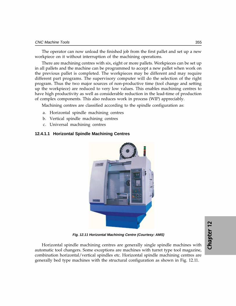
Ch
ap
ter
12C
ha
pte
r 12
Ch
ap
ter
12C
ha
pte
r 12
Ch
ap
ter
12
355CNC Machine Tools
The operator can now unload the finished job from the first pallet and set up a newworkpiece on it without interruption of the machining operations.
There are machining centres with six, eight or more pallets. Workpieces can be set upin all pallets and the machine can be programmed to accept a new pallet when work onthe previous pallet is completed. The workpieces may be different and may requiredifferent part programs. The supervisory computer will do the selection of the rightprogram. Thus the two major sources of non-productive time (tool change and settingup the workpiece) are reduced to very low values. This enables machining centres tohave high productivity as well as considerable reduction in the lead-time of productionof complex components. This also reduces work in process (WIP) appreciably.
Machining centres are classified according to the spindle configuration as:
a. Horizontal spindle machining centresb. Vertical spindle machining centresc. Universal machining centres
12.4.1.1 Horizontal Spindle Machining Centres
Fig. 12.11 Horizontal Machining Centre (Courtesy: AMS)
Horizontal spindle machining centres are generally single spindle machines withautomatic tool changers. Some exceptions are machines with turret type tool magazine,combination horizontal/vertical spindles etc. Horizontal spindle machining centres aregenerally bed type machines with the structural configuration as shown in Fig. 12.11.
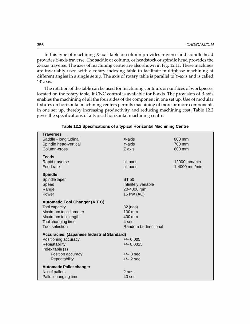
356 CAD/CAM/CIM
In this type of machining X-axis table or column provides traverse and spindle headprovides Y-axis traverse. The saddle or column, or headstock or spindle head provides theZ-axis traverse. The axes of machining centre are also shown in Fig. 12.11. These machinesare invariably used with a rotary indexing table to facilitate multiphase machining atdifferent angles in a single setup. The axis of rotary table is parallel to Y-axis and is called‘B’ axis.
The rotation of the table can be used for machining contours on surfaces of workpieceslocated on the rotary table, if CNC control is available for B-axis. The provision of B-axisenables the machining of all the four sides of the component in one set up. Use of modularfixtures on horizontal machining centers permits machining of more or more componentsin one set up, thereby increasing productivity and reducing machining cost. Table 12.2gives the specifications of a typical horizontal machining centre.
Table 12.2 Specifications of a typical Horizontal Machining Centre
TraversesSaddle - longitudinal X-axis 800 mmSpindle head-vertical Y-axis 700 mmColumn-cross Z axis 800 mm
FeedsRapid traverse all axes 12000 mm/minFeed rate all axes 1-4000 mm/min
SpindleSpindle taper BT 50Speed Infinitely variableRange 20-4000 rpmPower 15 kW (AC)
Automatic Tool Changer (A T C)Tool capacity 32 (nos)Maximum tool diameter 100 mmMaximum tool length 400 mmTool changing time 4 secTool selection Random bi-directional
Accuracies: (Japanese Industrial Standard)Positioning accuracy +/– 0.005Repeatability +/– 0.0025Index table (1)
Position accuracy +/– 3 secRepeatability +/– 2 sec
Automatic Pallet changerNo. of pallets 2 nosPallet changing time 40 sec
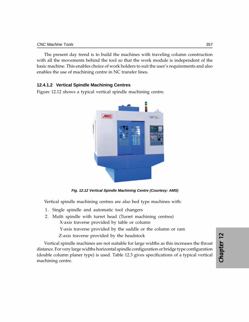
Ch
ap
ter
12C
ha
pte
r 12
Ch
ap
ter
12C
ha
pte
r 12
Ch
ap
ter
12
357CNC Machine Tools
The present day trend is to build the machines with traveling column constructionwith all the movements behind the tool so that the work module is independent of thebasic machine. This enables choice of work holders to suit the user’s requirements and alsoenables the use of machining centre in NC transfer lines.
12.4.1.2 Vertical Spindle Machining Centres
Figure 12.12 shows a typical vertical spindle machining centre.
Fig. 12.12 Vertical Spindle Machining Centre (Courtesy: AMS)
Vertical spindle machining centres are also bed type machines with:
1. Single spindle and automatic tool changers2. Multi spindle with turret head (Turret machining centres)
X-axis traverse provided by table or columnY-axis traverse provided by the saddle or the column or ramZ-axis traverse provided by the headstock
Vertical spindle machines are not suitable for large widths as this increases the throatdistance. For very large widths horizontal spindle configuration or bridge type configuration(double column planer type) is used. Table 12.3 gives specifications of a typical verticalmachining centre.
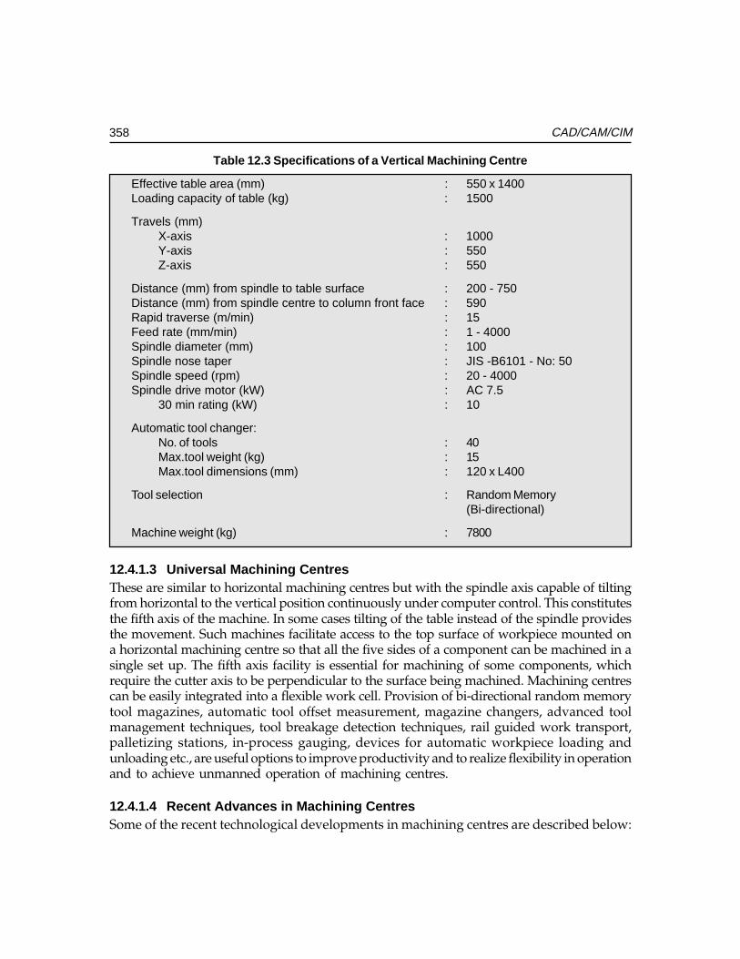
358 CAD/CAM/CIM
Table 12.3 Specifications of a Vertical Machining Centre
Effective table area (mm) : 550 x 1400Loading capacity of table (kg) : 1500
Travels (mm)X-axis : 1000Y-axis : 550Z-axis : 550
Distance (mm) from spindle to table surface : 200 - 750Distance (mm) from spindle centre to column front face : 590Rapid traverse (m/min) : 15Feed rate (mm/min) : 1 - 4000Spindle diameter (mm) : 100Spindle nose taper : JIS -B6101 - No: 50Spindle speed (rpm) : 20 - 4000Spindle drive motor (kW) : AC 7.5
30 min rating (kW) : 10
Automatic tool changer:No. of tools : 40Max.tool weight (kg) : 15Max.tool dimensions (mm) : 120 x L400
Tool selection : Random Memory(Bi-directional)
Machine weight (kg) : 7800
12.4.1.3 Universal Machining CentresThese are similar to horizontal machining centres but with the spindle axis capable of tiltingfrom horizontal to the vertical position continuously under computer control. This constitutesthe fifth axis of the machine. In some cases tilting of the table instead of the spindle providesthe movement. Such machines facilitate access to the top surface of workpiece mounted ona horizontal machining centre so that all the five sides of a component can be machined in asingle set up. The fifth axis facility is essential for machining of some components, whichrequire the cutter axis to be perpendicular to the surface being machined. Machining centrescan be easily integrated into a flexible work cell. Provision of bi-directional random memorytool magazines, automatic tool offset measurement, magazine changers, advanced toolmanagement techniques, tool breakage detection techniques, rail guided work transport,palletizing stations, in-process gauging, devices for automatic workpiece loading andunloading etc., are useful options to improve productivity and to realize flexibility in operationand to achieve unmanned operation of machining centres.
12.4.1.4 Recent Advances in Machining CentresSome of the recent technological developments in machining centres are described below:
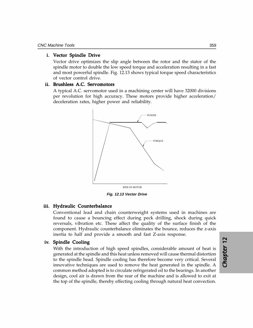
Ch
ap
ter
12C
ha
pte
r 12
Ch
ap
ter
12C
ha
pte
r 12
Ch
ap
ter
12
359CNC Machine Tools
i.i.i.i.i. Vector Spindle DriveVector Spindle DriveVector Spindle DriveVector Spindle DriveVector Spindle DriveVector drive optimizes the slip angle between the rotor and the stator of thespindle motor to double the low speed torque and acceleration resulting in a fastand most powerful spindle. Fig. 12.13 shows typical torque speed characteristicsof vector control drive.
ii.ii.ii.ii.ii. Brushless A.C. ServomotorsBrushless A.C. ServomotorsBrushless A.C. ServomotorsBrushless A.C. ServomotorsBrushless A.C. ServomotorsA typical A.C. servomotor used in a machining center will have 32000 divisionsper revolution for high accuracy. These motors provide higher acceleration/deceleration rates, higher power and reliability.
RPM OF MOTOR
TORQUE
POWER
Fig. 12.13 Vector Drive
iii.iii.iii.iii.iii. Hydraulic CounterbalanceHydraulic CounterbalanceHydraulic CounterbalanceHydraulic CounterbalanceHydraulic CounterbalanceConventional lead and chain counterweight systems used in machines arefound to cause a bouncing effect during peck drilling, shock during quickreversals, vibration etc. These affect the quality of the surface finish of thecomponent. Hydraulic counterbalance eliminates the bounce, reduces the z-axisinertia to half and provide a smooth and fast Z-axis response.
iviviviviv..... Spindle CoolingSpindle CoolingSpindle CoolingSpindle CoolingSpindle CoolingWith the introduction of high speed spindles, considerable amount of heat isgenerated at the spindle and this heat unless removed will cause thermal distortionto the spindle head. Spindle cooling has therefore become very critical. Severalinnovative techniques are used to remove the heat generated in the spindle. Acommon method adopted is to circulate refrigerated oil to the bearings. In anotherdesign, cool air is drawn from the rear of the machine and is allowed to exit atthe top of the spindle, thereby effecting cooling through natural heat convection.
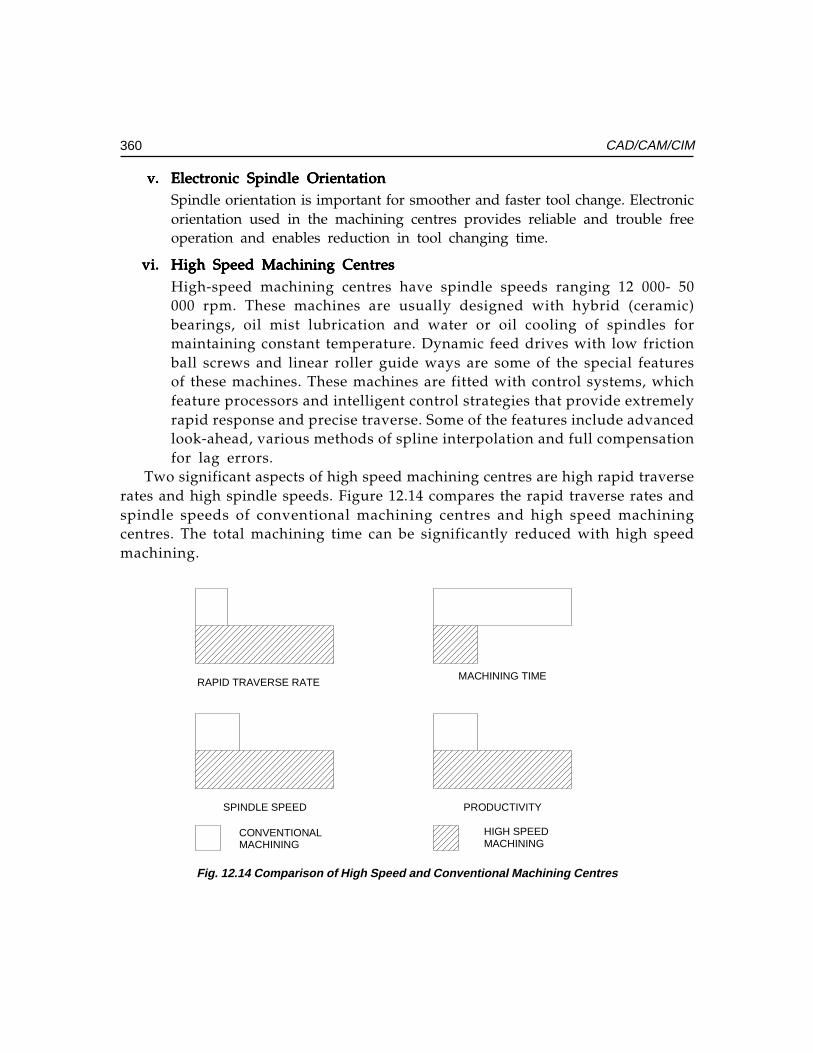
360 CAD/CAM/CIM
v.v.v.v.v. Electronic Spindle OrientationElectronic Spindle OrientationElectronic Spindle OrientationElectronic Spindle OrientationElectronic Spindle OrientationSpindle orientation is important for smoother and faster tool change. Electronicorientation used in the machining centres provides reliable and trouble freeoperation and enables reduction in tool changing time.
vi.vi.vi.vi.vi. High Speed Machining CentresHigh Speed Machining CentresHigh Speed Machining CentresHigh Speed Machining CentresHigh Speed Machining CentresHigh-speed machining centres have spindle speeds ranging 12 000- 50000 rpm. These machines are usually designed with hybrid (ceramic)bearings, oil mist lubrication and water or oil cooling of spindles formaintaining constant temperature. Dynamic feed drives with low frictionball screws and linear roller guide ways are some of the special featuresof these machines. These machines are fitted with control systems, whichfeature processors and intelligent control strategies that provide extremelyrapid response and precise traverse. Some of the features include advancedlook-ahead, various methods of spline interpolation and full compensationfor lag errors.
Two significant aspects of high speed machining centres are high rapid traverserates and high spindle speeds. Figure 12.14 compares the rapid traverse rates andspindle speeds of conventional machining centres and high speed machiningcentres. The total machining time can be significantly reduced with high speedmachining.
RAPID TRAVERSE RATE
CONVENTIONAL
SPINDLE SPEED
MACHINING
MACHINING TIME
HIGH SPEED
PRODUCTIVITY
MACHINING
Fig. 12.14 Comparison of High Speed and Conventional Machining Centres
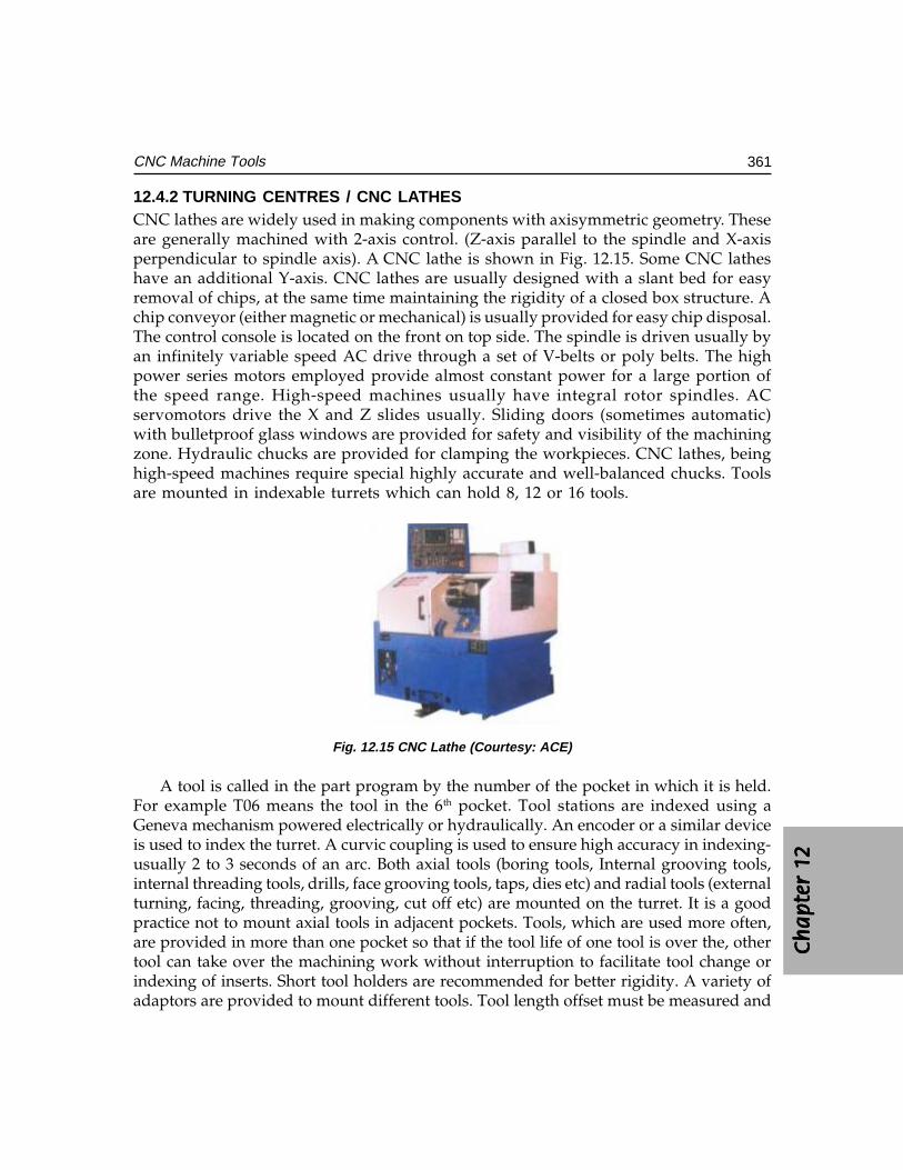
Ch
ap
ter
12C
ha
pte
r 12
Ch
ap
ter
12C
ha
pte
r 12
Ch
ap
ter
12
361CNC Machine Tools
12.4.2 TURNING CENTRES / CNC LATHESCNC lathes are widely used in making components with axisymmetric geometry. Theseare generally machined with 2-axis control. (Z-axis parallel to the spindle and X-axisperpendicular to spindle axis). A CNC lathe is shown in Fig. 12.15. Some CNC latheshave an additional Y-axis. CNC lathes are usually designed with a slant bed for easyremoval of chips, at the same time maintaining the rigidity of a closed box structure. Achip conveyor (either magnetic or mechanical) is usually provided for easy chip disposal.The control console is located on the front on top side. The spindle is driven usually byan infinitely variable speed AC drive through a set of V-belts or poly belts. The highpower series motors employed provide almost constant power for a large portion ofthe speed range. High-speed machines usually have integral rotor spindles. ACservomotors drive the X and Z slides usually. Sliding doors (sometimes automatic)with bulletproof glass windows are provided for safety and visibility of the machiningzone. Hydraulic chucks are provided for clamping the workpieces. CNC lathes, beinghigh-speed machines require special highly accurate and well-balanced chucks. Toolsare mounted in indexable turrets which can hold 8, 12 or 16 tools.
Fig. 12.15 CNC Lathe (Courtesy: ACE)
A tool is called in the part program by the number of the pocket in which it is held.For example T06 means the tool in the 6th pocket. Tool stations are indexed using aGeneva mechanism powered electrically or hydraulically. An encoder or a similar deviceis used to index the turret. A curvic coupling is used to ensure high accuracy in indexing-usually 2 to 3 seconds of an arc. Both axial tools (boring tools, Internal grooving tools,internal threading tools, drills, face grooving tools, taps, dies etc) and radial tools (externalturning, facing, threading, grooving, cut off etc) are mounted on the turret. It is a goodpractice not to mount axial tools in adjacent pockets. Tools, which are used more often,are provided in more than one pocket so that if the tool life of one tool is over the, othertool can take over the machining work without interruption to facilitate tool change orindexing of inserts. Short tool holders are recommended for better rigidity. A variety ofadaptors are provided to mount different tools. Tool length offset must be measured and
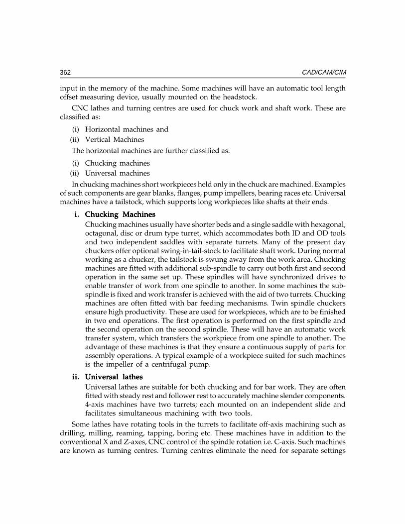
362 CAD/CAM/CIM
input in the memory of the machine. Some machines will have an automatic tool lengthoffset measuring device, usually mounted on the headstock.
CNC lathes and turning centres are used for chuck work and shaft work. These areclassified as:
(i) Horizontal machines and(ii) Vertical Machines
The horizontal machines are further classified as:
(i) Chucking machines(ii) Universal machines
In chucking machines short workpieces held only in the chuck are machined. Examplesof such components are gear blanks, flanges, pump impellers, bearing races etc. Universalmachines have a tailstock, which supports long workpieces like shafts at their ends.
i.i.i.i.i. Chucking MachinesChucking MachinesChucking MachinesChucking MachinesChucking MachinesChucking machines usually have shorter beds and a single saddle with hexagonal,octagonal, disc or drum type turret, which accommodates both ID and OD toolsand two independent saddles with separate turrets. Many of the present daychuckers offer optional swing-in-tail-stock to facilitate shaft work. During normalworking as a chucker, the tailstock is swung away from the work area. Chuckingmachines are fitted with additional sub-spindle to carry out both first and secondoperation in the same set up. These spindles will have synchronized drives toenable transfer of work from one spindle to another. In some machines the sub-spindle is fixed and work transfer is achieved with the aid of two turrets. Chuckingmachines are often fitted with bar feeding mechanisms. Twin spindle chuckersensure high productivity. These are used for workpieces, which are to be finishedin two end operations. The first operation is performed on the first spindle andthe second operation on the second spindle. These will have an automatic worktransfer system, which transfers the workpiece from one spindle to another. Theadvantage of these machines is that they ensure a continuous supply of parts forassembly operations. A typical example of a workpiece suited for such machinesis the impeller of a centrifugal pump.
ii.ii.ii.ii.ii. Universal lathesUniversal lathesUniversal lathesUniversal lathesUniversal lathesUniversal lathes are suitable for both chucking and for bar work. They are oftenfitted with steady rest and follower rest to accurately machine slender components.4-axis machines have two turrets; each mounted on an independent slide andfacilitates simultaneous machining with two tools.
Some lathes have rotating tools in the turrets to facilitate off-axis machining such asdrilling, milling, reaming, tapping, boring etc. These machines have in addition to theconventional X and Z-axes, CNC control of the spindle rotation i.e. C-axis. Such machinesare known as turning centres. Turning centres eliminate the need for separate settings
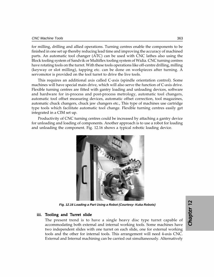
Ch
ap
ter
12C
ha
pte
r 12
Ch
ap
ter
12C
ha
pte
r 12
Ch
ap
ter
12
363CNC Machine Tools
for milling, drilling and allied operations. Turning centres enable the components to befinished in one set up thereby reducing lead time and improving the accuracy of machinedparts. An automatic tool changer (ATC) can be used with CNC lathes also using theBlock tooling system of Sandvik or Multiflex tooling system of Widia. CNC turning centreshave rotating tools on the turret. With these tools operations like off-centre drilling, milling(keyway or slot milling), tapping etc. can be done on workpieces after turning. Aservomotor is provided on the tool turret to drive the live tools.
This requires an additional axis called C-axis (spindle orientation control). Somemachines will have special main drive, which will also serve the function of C-axis drive.Flexible turning centres are fitted with gantry loading and unloading devices, softwareand hardware for in-process and post-process metrology, automatic tool changers,automatic tool offset measuring devices, automatic offset correction, tool magazines,automatic chuck changers, chuck jaw changers etc., This type of machines use cartridgetype tools which facilitate automatic tool change. Flexible turning centres easily getintegrated in a CIM set up.
Productivity of CNC turning centres could be increased by attaching a gantry devicefor unloading and loading of components. Another approach is to use a robot for loadingand unloading the component. Fig. 12.16 shows a typical robotic loading device.
Fig. 12.16 Loading a Part Using a Robot (Courtesy- Kuka Robots)
iii.iii.iii.iii.iii. TTTTTooling and Tooling and Tooling and Tooling and Tooling and Turrurrurrurrurret slideet slideet slideet slideet slideThe present trend is to have a single heavy disc type turret capable ofaccommodating both external and internal working tools. Some machines havetwo independent slides with one turret on each slide, one for external workingtools and the other for internal tools. This arrangement will need 4-axis CNC.External and Internal machining can be carried out simultaneously. Alternatively
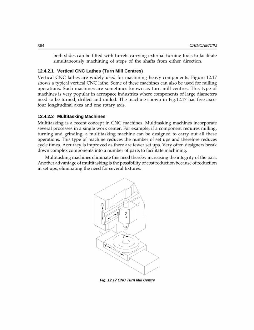
364 CAD/CAM/CIM
both slides can be fitted with turrets carrying external turning tools to facilitatesimultaneously machining of steps of the shafts from either direction.
12.4.2.1 Vertical CNC Lathes (Turn Mill Centres)Vertical CNC lathes are widely used for machining heavy components. Figure 12.17shows a typical vertical CNC lathe. Some of these machines can also be used for millingoperations. Such machines are sometimes known as turn mill centres. This type ofmachines is very popular in aerospace industries where components of large diametersneed to be turned, drilled and milled. The machine shown in Fig.12.17 has five axes-four longitudinal axes and one rotary axis.
12.4.2.2 Multitasking MachinesMultitasking is a recent concept in CNC machines. Multitasking machines incorporateseveral processes in a single work center. For example, if a component requires milling,turning and grinding, a multitasking machine can be designed to carry out all theseoperations. This type of machine reduces the number of set ups and therefore reducescycle times. Accuracy is improved as there are fewer set ups. Very often designers breakdown complex components into a number of parts to facilitate machining.
Multitasking machines eliminate this need thereby increasing the integrity of the part.Another advantage of multitasking is the possibility of cost reduction because of reductionin set ups, eliminating the need for several fixtures.
X
Y
Z
R
C
Fig. 12.17 CNC Turn Mill Centre
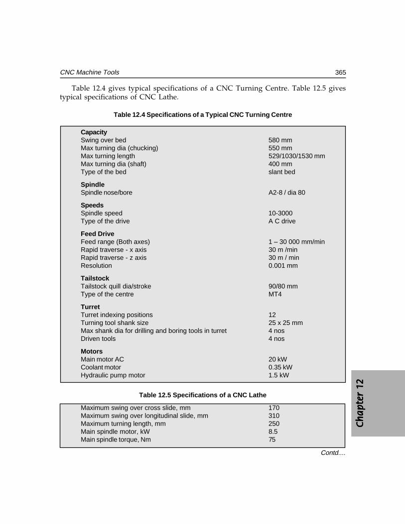
Ch
ap
ter
12C
ha
pte
r 12
Ch
ap
ter
12C
ha
pte
r 12
Ch
ap
ter
12
365CNC Machine Tools
Table 12.4 gives typical specifications of a CNC Turning Centre. Table 12.5 givestypical specifications of CNC Lathe.
Table 12.4 Specifications of a Typical CNC Turning Centre
CapacitySwing over bed 580 mmMax turning dia (chucking) 550 mmMax turning length 529/1030/1530 mmMax turning dia (shaft) 400 mmType of the bed slant bed
SpindleSpindle nose/bore A2-8 / dia 80
SpeedsSpindle speed 10-3000Type of the drive A C drive
Feed DriveFeed range (Both axes) 1 – 30 000 mm/minRapid traverse - x axis 30 m /minRapid traverse - z axis 30 m / minResolution 0.001 mm
TailstockTailstock quill dia/stroke 90/80 mmType of the centre MT4
TurretTurret indexing positions 12Turning tool shank size 25 x 25 mmMax shank dia for drilling and boring tools in turret 4 nosDriven tools 4 nos
MotorsMain motor AC 20 kWCoolant motor 0.35 kWHydraulic pump motor 1.5 kW
Table 12.5 Specifications of a CNC Lathe
Maximum swing over cross slide, mm 170Maximum swing over longitudinal slide, mm 310Maximum turning length, mm 250Main spindle motor, kW 8.5Main spindle torque, Nm 75
Contd....
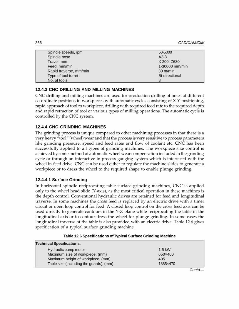
366 CAD/CAM/CIM
Spindle speeds, rpm 50-5000Spindle nose A2-8Travel, mm X 200, Z630Feed, mm/min 1-30000 mm/minRapid traverse, mm/min 30 m/minType of tool turret Bi-directionalNo. of tools 8
12.4.3 CNC DRILLING AND MILLING MACHINESCNC drilling and milling machines are used for production drilling of holes at differentco-ordinate positions in workpieces with automatic cycles consisting of X-Y positioning,rapid approach of tool to workpiece, drilling with required feed rate to the required depthand rapid retraction of tool or various types of milling operations. The automatic cycle iscontrolled by the CNC system.
12.4.4 CNC GRINDING MACHINESThe grinding process is unique compared to other machining processes in that there is avery heavy “tool” (wheel) wear and that the process is very sensitive to process parameterslike grinding pressure, speed and feed rates and flow of coolant etc. CNC has beensuccessfully applied to all types of grinding machines. The workpiece size control isachieved by some method of automatic wheel wear compensation included in the grindingcycle or through an interactive in-process gauging system which is interfaced with thewheel in-feed drive. CNC can be used either to regulate the machine slides to generate aworkpiece or to dress the wheel to the required shape to enable plunge grinding.
12.4.4.1 Surface GrindingIn horizontal spindle reciprocating table surface grinding machines, CNC is appliedonly to the wheel head slide (Y-axis), as the most critical operation in these machines isthe depth control. Conventional hydraulic drives are retained for feed and longitudinaltraverse. In some machines the cross feed is replaced by an electric drive with a timercircuit or open loop control for feed. A closed loop control on the cross feed axis can beused directly to generate contours in the Y-Z plane while reciprocating the table in thelongitudinal axis or to contour-dress the wheel for plunge grinding. In some cases thelongitudinal traverse of the table is also provided with an electric drive. Table 12.6 givesspecification of a typical surface grinding machine.
Table 12.6 Specifications of Typical Surface Grinding Machine
Technical Specifications:
Hydraulic pump motor 1.5 kWMaximum size of workpiece, (mm) 650×400Maximum height of workpiece, (mm) 405Table size (including the guards), (mm) 1885×470
Contd....
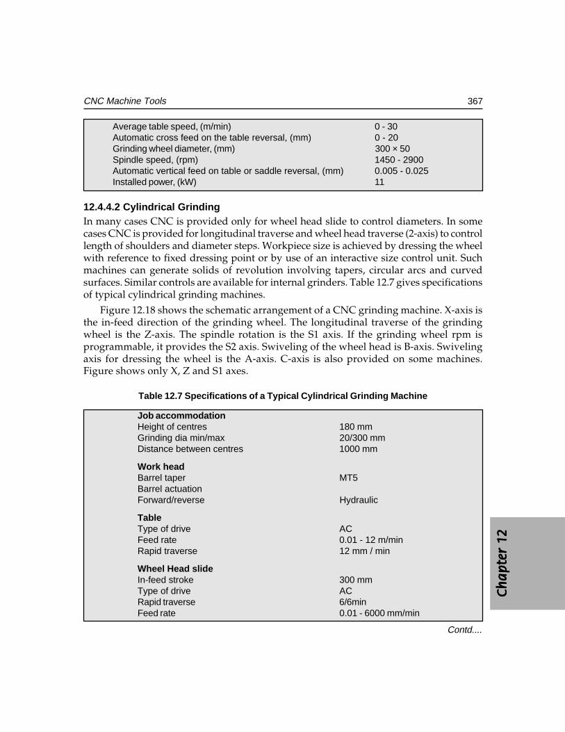
Ch
ap
ter
12C
ha
pte
r 12
Ch
ap
ter
12C
ha
pte
r 12
Ch
ap
ter
12
367CNC Machine Tools
Average table speed, (m/min) 0 - 30Automatic cross feed on the table reversal, (mm) 0 - 20Grinding wheel diameter, (mm) 300 × 50Spindle speed, (rpm) 1450 - 2900Automatic vertical feed on table or saddle reversal, (mm) 0.005 - 0.025Installed power, (kW) 11
12.4.4.2 Cylindrical GrindingIn many cases CNC is provided only for wheel head slide to control diameters. In somecases CNC is provided for longitudinal traverse and wheel head traverse (2-axis) to controllength of shoulders and diameter steps. Workpiece size is achieved by dressing the wheelwith reference to fixed dressing point or by use of an interactive size control unit. Suchmachines can generate solids of revolution involving tapers, circular arcs and curvedsurfaces. Similar controls are available for internal grinders. Table 12.7 gives specificationsof typical cylindrical grinding machines.
Figure 12.18 shows the schematic arrangement of a CNC grinding machine. X-axis isthe in-feed direction of the grinding wheel. The longitudinal traverse of the grindingwheel is the Z-axis. The spindle rotation is the S1 axis. If the grinding wheel rpm isprogrammable, it provides the S2 axis. Swiveling of the wheel head is B-axis. Swivelingaxis for dressing the wheel is the A-axis. C-axis is also provided on some machines.Figure shows only X, Z and S1 axes.
Table 12.7 Specifications of a Typical Cylindrical Grinding Machine
Job accommodationHeight of centres 180 mmGrinding dia min/max 20/300 mmDistance between centres 1000 mm
Work headBarrel taper MT5Barrel actuationForward/reverse Hydraulic
TableType of drive ACFeed rate 0.01 - 12 m/minRapid traverse 12 mm / min
Wheel Head slideIn-feed stroke 300 mmType of drive ACRapid traverse 6/6minFeed rate 0.01 - 6000 mm/min
Contd....
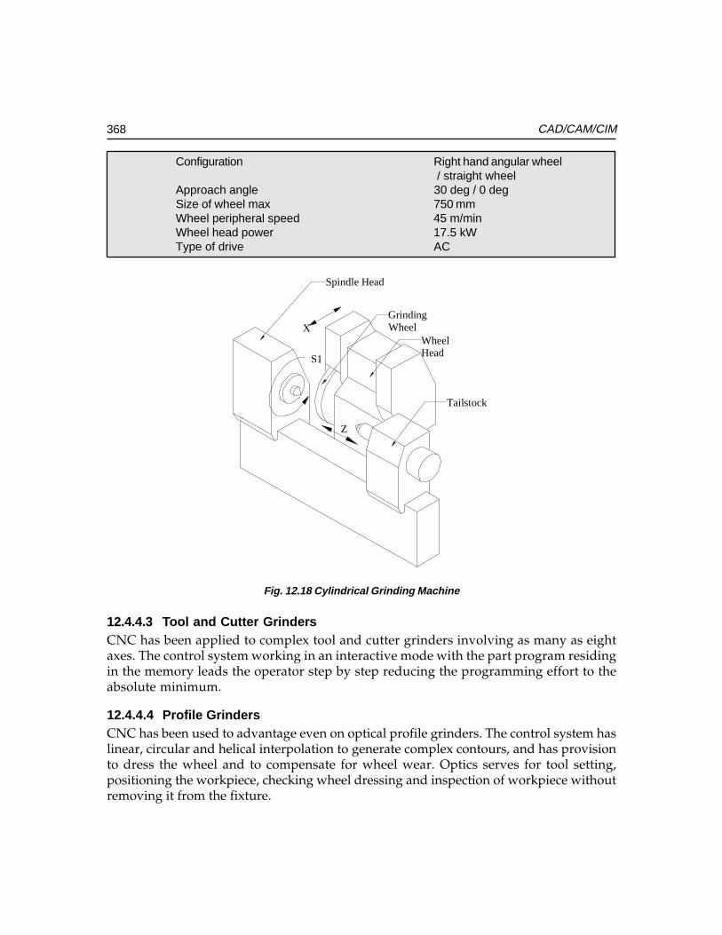
368 CAD/CAM/CIM
Configuration Right hand angular wheel / straight wheel
Approach angle 30 deg / 0 degSize of wheel max 750 mmWheel peripheral speed 45 m/minWheel head power 17.5 kWType of drive AC
X
S1
Z
GrindingWheel
WheelHead
Tailstock
Spindle Head
Fig. 12.18 Cylindrical Grinding Machine
12.4.4.3 Tool and Cutter GrindersCNC has been applied to complex tool and cutter grinders involving as many as eightaxes. The control system working in an interactive mode with the part program residingin the memory leads the operator step by step reducing the programming effort to theabsolute minimum.
12.4.4.4 Profile GrindersCNC has been used to advantage even on optical profile grinders. The control system haslinear, circular and helical interpolation to generate complex contours, and has provisionto dress the wheel and to compensate for wheel wear. Optics serves for tool setting,positioning the workpiece, checking wheel dressing and inspection of workpiece withoutremoving it from the fixture.
Ch
ap
ter
12C
ha
pte
r 12
Ch
ap
ter
12C
ha
pte
r 12
Ch
ap
ter
12
369CNC Machine Tools
12.4.5 ELECTRICAL DISCHARGE MACHININGElectric discharge machine is an important machine in tool rooms. There are severaltypes of electric discharge machines, which are fitted with computer numerical control.
12.4.5.1 Ram Type EDMIn this type of machine the electrode has to have the same size and shape of thecounterpart of the workpiece being machined. Servo control is used to maintain the gapbetween the electrode and the workpiece.
12.4.5.2 Orbital EDMIn this type of machines, the electrode is in the form of a ball-ended cutter and spinsabout its own axis. The relative position of the electrode and workpiece is regulated by a3-axis CNC system to generate any three dimensional surface.
12.4.5.3 Wire EDMWire cut EDM is an indispensable machine in tool rooms. This is used to make dies forblanking and piercing. The special feature of wire EDM is that the electrode is in the formof a thin wire of about 0.2 mm in dia. A small hole is drilled into the workpiece and thewire electrode is threaded through the workpiece onto a take-up roll. The movements ofthe work table through computer numerical control in X and Y directions enable cuttingthe component to the required shapes. In some cases where a relief is required for the dieor the punch being machined, a 3-axis NC is used to tilt the wire axis relative to workpiecesurface in the required direction. The direction of tilt varies with the contour and is controlledby the third axis of the CNC. Some of the latest wire EDM machines have the automaticdrilling and self threading facility.
12.4.6 TURRET PUNCH PRESSCNC has become very popular with punching and nibbling machine used for sheetmetal work. Many of these machines are equipped with a turret head. Such machinesare called turret punch presses. This machine is widely used in press shops. Mainapplication of the turret punch press is to cut various types of holes/openings in sheetmetal for manufacturing machine frames or control cabinets out of sheet metal. Modulartooling systems available simplify tooling. Interactive programming facilities are availablewith the machine controls. Off line programming and simulation are adopted to utilizethe machine fully and to obtain correct workpiece. Some of the turret punch presseshave an additional plasma arc or a laser cutting head to generate contoured patterns.Some of the latest machines have automatic work handling, automatic tool change andautomatic measuring systems interfaced with the machine. CNC has also been appliedto other forming machines such as plate bending, tube bending, flow turning and stretchforming as well. Table 12.8 gives specifications of a typical CNC Turret Punch Press.
370 CAD/CAM/CIM
Table 12.8 Specifications of a Typical Turret Punch Press
Sheet size with one reposition 2040 x 1540 mmAxis speed 40 m/minMax sheet weight 75 kgMax material thickness (MS) 6.35 mmPunching accuracy +/-0.13 mmTurret layout 15 stationsNibbling rate 180 hmpMax hit rate @25 mm increments 180 hmpRam stroke 25 mmMinimum material thickness 0.8 mmPress motor 4.5 kWAxis drive AC servoClutch Air combinationBrake Air combinationWeight 8100 kgRegrinding life of punch 10 mm
12.4.7 GEAR CUTTING MACHINESCNC has been introduced to automate various types of gear cutting machines.
• Gear Hobbing Machines• Gear Shaping Machines• Gear Grinders• Bevel Gear Generators
CNC enables elimination of change gears in gear cutting machines. The relativerotary and translation movements of the tool and the workpiece are controlled by CNCsystems and can be easily programmed through keyboard of CNC system to facilitatequick setting up of the machine. CNC gear cutting machines employ the concept of anelectronic gearbox. CNC increases both the productivity and accuracy of gear cuttingmachine appreciably.
Three to six-axis control is very common in CNC gear hobbing machines. Many CNCgear hobbing machines incorporate direct hob drives, automatic hob shift, quick-changehobs, and automatic hob head swiveling. High-speed hob spindles make effective use ofmulti-start TiN coated, carbide coated or carbide insert hobs. Table 12.9 gives specificationsof a typical Gear Hobbing Machine.
Use of CNC in gear shaping machine eliminates the need for change gears. CNC controlis provided for the axial movement of cutter head slide, radial movement of column slide,rotary movement of cutter spindle and rotary movement of worktable.
Ch
ap
ter
12C
ha
pte
r 12
Ch
ap
ter
12C
ha
pte
r 12
Ch
ap
ter
12
371CNC Machine Tools
Table 12.9 Specifications of a Typical Gear Hobbing Machine
Max dia of workpiece 200 mmMax module in steel 6 mmMax axial travel 250 mmMin/max no. of teeth 6/120
Working rangeDia of work table/bore 215/60 mmDistance between hob and work axis 220 (max): 20 (min)Max dia. of hob 150 mmMax length of hob 220 mmMax hob shift 170 mmMax helix angle 45 deg
Speeds and feedsHob speed 120-500 rpmWork speed 50 rpmAxial feed 1-3000 mm/minRadial feed 1-3000 mm/minTangential feed 1-540 mm/minHob swiveling 1-500 deg/minCNC system 6 axes CNC control system,
Sinumerik 3GA with electronicGear box for synchronization
PowerMain motor 12.5 kW
12.4.8 CNC PRESS BRAKESA press brake is basically a sheet bending machine. This machine finds extensive use infabrication of control panels, enclosures etc. Provision of CNC increases the productivityand significantly improves the quality of the final product. CNC systems of press brakesprovide interactive help for programming. A tool library is also provided. Simulationcapability in the programming software helps in the development of correct programs.
12.4.9 SPECIAL PURPOSE CNC MACHINESMany SPM’s are now designed with computer numerical control to provide the necessaryflexibility to the machine. A typical example is a moving column SPM that is designed forboring and reaming operations. Under the guidance of CNC the tool is positioned at adesired point or the tool is made to follow any contour for machining operations. Switchover from one type of machining operations to other is completely automatic through theprovision of Automatic Tool Changer (ATC). The column traverse and fixed table modulecontribute to higher transfer efficiency and flexibility in line production. Hence these CNCspecial purpose machines can be integrated with other machine tools into flexiblemanufacturing line for greater flexibility in producing a variety of totally finished
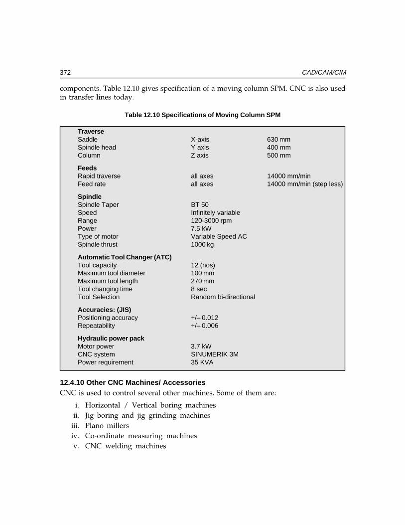
372 CAD/CAM/CIM
components. Table 12.10 gives specification of a moving column SPM. CNC is also usedin transfer lines today.
Table 12.10 Specifications of Moving Column SPM
TraverseSaddle X-axis 630 mmSpindle head Y axis 400 mmColumn Z axis 500 mm
FeedsRapid traverse all axes 14000 mm/minFeed rate all axes 14000 mm/min (step less)
SpindleSpindle Taper BT 50Speed Infinitely variableRange 120-3000 rpmPower 7.5 kWType of motor Variable Speed ACSpindle thrust 1000 kg
Automatic Tool Changer (ATC)Tool capacity 12 (nos)Maximum tool diameter 100 mmMaximum tool length 270 mmTool changing time 8 secTool Selection Random bi-directional
Accuracies: (JIS)Positioning accuracy +/– 0.012Repeatability +/– 0.006
Hydraulic power packMotor power 3.7 kWCNC system SINUMERIK 3MPower requirement 35 KVA
12.4.10 Other CNC Machines/ AccessoriesCNC is used to control several other machines. Some of them are:
i. Horizontal / Vertical boring machinesii. Jig boring and jig grinding machines
iii. Plano millersiv. Co-ordinate measuring machinesv. CNC welding machines
Ch
ap
ter
12C
ha
pte
r 12
Ch
ap
ter
12C
ha
pte
r 12
Ch
ap
ter
12
373CNC Machine Tools
vi. Assembly machinesvii. Printed circuit board drilling machines
viii. CNC forming machines
• Tube bending machines• Plate bending machines• Stretch forming machines• Flow forming machines
ix. Tool handling systemsx. Work handling systems
xi. Cleaning and washing stationsxii. Heat treatment equipment
xiii. Packaging equipmentxiv. Electron beam welding machinexv. Fettling machines
xvi. CNC press brakesxvii. Laser cutting machines
xviii. Water jet cutting machines.
12.4.11 USE OF CNC MACHINES AS INSPECTION MACHINESSince CNC machine slides are fitted with feedback devices, they can also be used forpost process metrology. Many of the present day machines are fitted with touch triggerprobes, which can be used for inspection of workpiece and for setting the tool offsets.On machining centres the probe can be stored in one of the pockets of the tool magazine.The probe is inserted into the spindle under program control and then can be used like aco-ordinate measuring machine to inspect the component being machined.
The probe can be used to compensate for fixture offsets, thermal deformations etc. Asimilar probe located at a fixed reference point can be used to set the offsets of the toolslocated in the spindle. Such probes are also used on turning machines to set the tool offsetsand for monitoring the size of the workpiece.
12.5 FEATURES OF CNC SYSTEMS
The brain of a CNC machine is the control system. This is designed around one or moreof the advanced microprocessors. Because of the advancement in the hardwaretechnology, CNC systems are highly reliable with a very high mean time between failures.Several control systems, which are dedicated to different families of machines, areavailable today. Each model will have several variations to cater to the variousrequirements of machine tool builders and users. Several new CNC systems are fittedwith PC based CNC systems too. A CNC system can be fitted to machine tools in order
374 CAD/CAM/CIM
to effect control over several machine functions. In order to perform these functions, aCNC system is characterized by a number of features. These functions can be broadlyclassified as follows:
i. Control system featuresii. Memory features
iii. Programming featuresiv. PLC featuresv. Diagnostic features
12.5.1 CONTROL SYSTEM FEATURESThese features provide information about the characteristics of the CNC system and itscapabilities. Important features are given below:
12.5.1.1 Technology of SystemCurrently two types of architectures are being used in CNC systems
(i) Single microprocessor based systems(ii) Multi microprocessor based systems (Multiprocessor systems)
Single microprocessor architecture: Single microprocessor architecture: Single microprocessor architecture: Single microprocessor architecture: Single microprocessor architecture: In this type of system a 16, 32 or 64 bitmicroprocessor is used.
Multiprocessor architecture:Multiprocessor architecture:Multiprocessor architecture:Multiprocessor architecture:Multiprocessor architecture: This type of the architecture is widely used in many CNCsystems today. The control functions are carried out by a set of microprocessors, each doingan assigned task. This concept helps to implement various functions faster. Both hardwareand software structures are modular thereby enhancing the flexibility of the system.
12.5.1.2 Executive ProgramThe executive program contains the intelligence needed to carry out different tasks inCNC system. The executive program is resident usually in EPROM/Bubble memory.
12.5.1.3 Other System FeaturesOther features of CNC system are:
• C R T display and alphanumeric keyboard• Manual data input (M D I) and operator programming• System resolution, ex: 0.1 µm, 0.5 µm, 1 µm or 10 µm• Feed and rapid traverse rates• Spindle Speeds - directly programmable or through S codes• Modes of operation like M D I, Single step, Auto etc.• Operating controls like Jog, feedrate and spindle speed override, axis select
switch, edit, reference, dry run, test mode
Ch
ap
ter
12C
ha
pte
r 12
Ch
ap
ter
12C
ha
pte
r 12
Ch
ap
ter
12
375CNC Machine Tools
12.5.1.4 Axis CalibrationThis is a very useful feature for obtaining higher positioning accuracy. The error in thepitch of the lead screw can be compensated with this feature.
12.5.1.5 Reversal Error (Backlash) Compensation
Backlash is due to the play between the screw and nut. Backlash will cause lost motionwhen the slides are reversed. Even pre-loaded ball screws may develop backlash in thecourse of time. This feature effects automatic compensation every time the slide is reversed.Error due to backlash in the lead screw can thus be minimized.
12.5.1.6 Pitch Error Compensation
There are several classes of accuracy for ball screws. There will always be some error frompitch to pitch, however accurate the screw may be. Pitch error will cause error in positioningas well as thread cutting. Hence there is a need to compensate pitch error. The positioningerrors that might arise due to error in pitch are compensated through software.
12.5.1.7 Tool Nose Radius Compensation
The radius of the tool will introduce positioning errors in contouring. This error iscompensated by the tool nose radius compensation function.
12.5.1.8 Machine Setup Data (MSD)MSD or machine tool parameters indicate the machine tool characteristics,specifications and functions. The contents of each parameter should be set accordingto the parameter list annexed to the machine. The end user must not change thecontents on the parameters. The OEM can use one standard control on several machinesizes and/or types.
Entering machine parameters: These are three methods of entering machineparameters.
i. Setting through parameter CD-ROM-each block contains a machine set up datacode to identify the machine parameter followed by data for that parameter.
ii. Setting data through MDI - the machine data can be input through the operator’scontrol panel by following the procedure for the control system.
iii. Setting data in EPROM’s - machine parameters can be entered in the erasableprogrammable read only memories. The data is permanently stored in specificlocations in the memory chip. To enter the set up data in EPROM, an EPROMprogrammer is necessary.
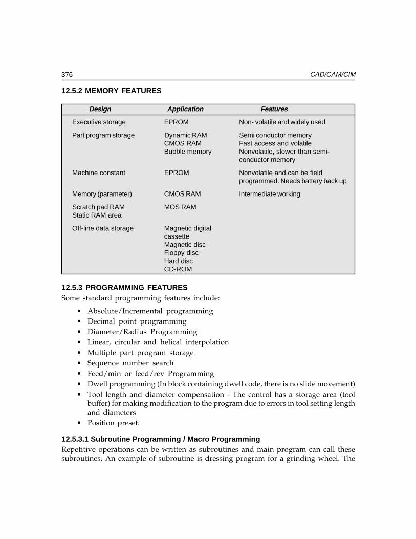
376 CAD/CAM/CIM
12.5.2 MEMORY FEATURES
Design Application Features
Executive storage EPROM Non- volatile and widely used
Part program storage Dynamic RAM Semi conductor memoryCMOS RAM Fast access and volatileBubble memory Nonvolatile, slower than semi-
conductor memory
Machine constant EPROM Nonvolatile and can be fieldprogrammed. Needs battery back up
Memory (parameter) CMOS RAM Intermediate working
Scratch pad RAM MOS RAMStatic RAM area
Off-line data storage Magnetic digitalcassetteMagnetic discFloppy discHard discCD-ROM
12.5.3 PROGRAMMING FEATURESSome standard programming features include:
• Absolute/Incremental programming• Decimal point programming• Diameter/Radius Programming• Linear, circular and helical interpolation• Multiple part program storage• Sequence number search• Feed/min or feed/rev Programming• Dwell programming (In block containing dwell code, there is no slide movement)• Tool length and diameter compensation - The control has a storage area (tool
buffer) for making modification to the program due to errors in tool setting lengthand diameters
• Position preset.
12.5.3.1 Subroutine Programming / Macro ProgrammingRepetitive operations can be written as subroutines and main program can call thesesubroutines. An example of subroutine is dressing program for a grinding wheel. The
Ch
ap
ter
12C
ha
pte
r 12
Ch
ap
ter
12C
ha
pte
r 12
Ch
ap
ter
12
377CNC Machine Tools
advantage of using this subroutine is that it eliminates the need for rewriting a repetitiveoperation, thereby saving the memory space.
12.5.3.2 Parametric ProgrammingParameters are freely assigned by the control for the purpose of arithmetic calculation ina part program. Trigonometric operations are also possible with R parameters.
12.5.3.3 Canned Cycles (Fixed Cycles)This is a powerful control feature intended to shorten the length of the part programthereby conserving memory space. Canned cycles are single block multi pass fixed cycles.
Examples:Examples:Examples:Examples:Examples: Canned cycles for rough turning and peck drilling in CNC Lathes. Cannedcycles for drilling, boring and tapping in machining centres.
12.5.4 PROGRAMMABLE LOGIC CONTROLLERProgrammable logic controller is a software oriented machine interface between theCNC system and machine tool functions such as miscellaneous functions (coolant on /off, pallet operation, spindle speed functions (M00, M01, M03, M04, etc) and toolfunctions). Signals from CNC to PLC are on /off type. The programmable logic controllersavailable today are microprocessor-based units, which are integrated into the CNC system.The programmable logic controllers have memory space to store interface programs.
Some of the common P L C features are listed below:
• Number of inputs and outputs 24, 32, 48 etc., (Both analog and digital)• Memory capacity 4 k, 8 k etc.• High-speed microprocessor to execute sequence program processing time of the
order of milliseconds• Software timers and counters• Data exchange between CNC and PLC
12.5.5 DIAGNOSTIC FEATURESThe CNC systems have diagnostics features for faults or error conditions. Diagnosticsare software programs, which check the functioning of the CNC system at various levels.The control system manufacturer gives detailed use and applications of these diagnosticprograms. Diagnostics can be grouped as follows:
i. Real time diagnosticsii. On-line diagnostics
iii. Off-line diagnostics
Real Time Diagnostics:Real Time Diagnostics:Real Time Diagnostics:Real Time Diagnostics:Real Time Diagnostics:D C power supply voltages, low voltage and real time clock are monitored. In case of
failure of any one of these, control system automatically assumes the emergency stopconditions and shuts down the drives.
378 CAD/CAM/CIM
On-line Diagnostics:On-line Diagnostics:On-line Diagnostics:On-line Diagnostics:On-line Diagnostics:On-line diagnostics are active during machine operation. Diagnostic messages are
either readable from C R T screen or from LED Indicators. Program diagnostics detectprogramming errors. (Syntax, Parity etc.)
Off-line Diagnostics:Off-line Diagnostics:Off-line Diagnostics:Off-line Diagnostics:Off-line Diagnostics:It is provided in the form of a CD-ROM or ROM board (PCB). Following a malfunction,
the off-line diagnostic programs are to be loaded which check the different areas of thesystem and respond with error codes / error description on C R T Display. Diagnostics arevery powerful features of CNC systems. To be productive, the system should have a lowMTTR (Mean Time to Repair).
Remote Diagnostics:Remote Diagnostics:Remote Diagnostics:Remote Diagnostics:Remote Diagnostics:It is now possible to send diagnostic programs through Internet to check the errors in
CNC Machines. This enables manufacturers to locate faults even if the machine is locatedin a remote place in another country.
12.5.6 SOME FEATURES OF MODERN CNC SYSTEMS
(i) Advanced hardware architecture:Advanced hardware architecture:Advanced hardware architecture:Advanced hardware architecture:Advanced hardware architecture: Custom built very large scale integrated circuits(VLSI) which can handle several functions in a single chip are used in modernCNC systems. This way, the benefits of reduced component count and improvedreliability are realized.
(ii) Software modularity: Software modularity: Software modularity: Software modularity: Software modularity: Each function is written as a discrete module - (structuredprogramming). Additional software features can be added at any time to upgradethe control without affecting the software.
(iii) Adaptive control:Adaptive control:Adaptive control:Adaptive control:Adaptive control: Reduces the production time by maximizing the utilization ofthe machine tool. It acts on measurement taken from external sensors (In-processmeasurement) and modifies the cutting conditions suitably.
(iv) Conversational programming: Conversational programming: Conversational programming: Conversational programming: Conversational programming: The system featuring conversational programmingare termed “user friendly” since they are designed with the operator in mind.One example of such a friendly feature is graphic display. With this feature, theoperator can create the part drawing on screen and simulate the tool paths in thepreparatory phase (Prior to machining). The operator can program in completesafety and be sure that nothing is omitted. The operator can also check thecorrectness of the part program on graphic display.
(v) Programming flexibility: InProgramming flexibility: InProgramming flexibility: InProgramming flexibility: InProgramming flexibility: In addition to conversational part programminglanguage, high level language commands like IF-THEN ELSE, GO TO etc., canbe used to extend the program’s power. Higher mathematical functions can beused to calculate square roots, trigonometric functions etc.
(vi) DNC link. DNC link. DNC link. DNC link. DNC link. This is discussed separately in detail later.
Ch
ap
ter
12C
ha
pte
r 12
Ch
ap
ter
12C
ha
pte
r 12
Ch
ap
ter
12
379CNC Machine Tools
(vii) Colour graphics: Colour graphics: Colour graphics: Colour graphics: Colour graphics: This provides visual interface between the operator and CNC.Part cross sections can be highlighted. Operating instructions and warningdisplay can be colour coded for more clarity.
(viii) Machine interface:Machine interface:Machine interface:Machine interface:Machine interface: A high-level language like C is used for programming themachine logic in PC (example: GE 2000 MC). In AB8600, high-level languageSIPROM (System Interface-Programming) is used.
(ix) Automatic selection of cutting speeds:Automatic selection of cutting speeds:Automatic selection of cutting speeds:Automatic selection of cutting speeds:Automatic selection of cutting speeds: If we specify the tool material and workmaterial, C N C System selects cutting speed and feed from cutting conditiontechnology database.
(x) Automatic selection of tools and sequencing of tools:Automatic selection of tools and sequencing of tools:Automatic selection of tools and sequencing of tools:Automatic selection of tools and sequencing of tools:Automatic selection of tools and sequencing of tools: If operation is specified,system selects corresponding tools and sequence of tools. Systems like MazakFusion 640 provides this knowledge based approach.
(xi) Optimization of machine program:Optimization of machine program:Optimization of machine program:Optimization of machine program:Optimization of machine program: This feature will be useful for componentswith large number of drilling, tapping operations, or repetitive end milling toolpaths as in the case of machining of dies and molds etc.
(xii) Display of finished component: Display of finished component: Display of finished component: Display of finished component: Display of finished component: Today CNC systems offer a feature to display thefinished component together with dimensions. Sectioning and rotation of themodel of the finished part are also possible.
(xiii) Background programming: Background programming: Background programming: Background programming: Background programming: It is a common facility available in CNC systems. Theuser can run, edit and simulate another program while a program is beingexecuted on the machine tool.
(xiv) Digital CNC:Digital CNC:Digital CNC:Digital CNC:Digital CNC: The new breed of CNC controls use digital technology. Theintroduction of digital CNC has brought increased speed and precision to machinetool builders. The PC based open architecture controls incorporate such featureslike acceleration with jerk limitation, direct NURBS interpolation, use of highlevel languages, execution of large CNC programs from hard disc and increasednumber of zero offsets. In some of the systems the CNC and drive amplifiers areon the some board at the digital level.
(xv) Look ahead feature:Look ahead feature:Look ahead feature:Look ahead feature:Look ahead feature: The control system scans 150 or more blocks ahead of theblock that is being executed and carries out interpolation and calculates theacceleration and deceleration requirements in the case of generation of complextool paths. This helps to produce accurate profiles in high speed machining.
12.6 DIRECT NUMERICAL CONTROL (DNC)
Early NC machines used a tape reader for storing and inputting the program into thememory of the NC machine tool. Because of the unreliability of the tape reader as well asthe low speed of operation NC engineers were searching for a suitable alternative. Theadvent of CNC in mid-sixtees opened up the possibility of improving the performance ofNC machines by interfacing them with minicomputers. Yet another significanttechnological development was the interfacing of several NC machines with a computer,
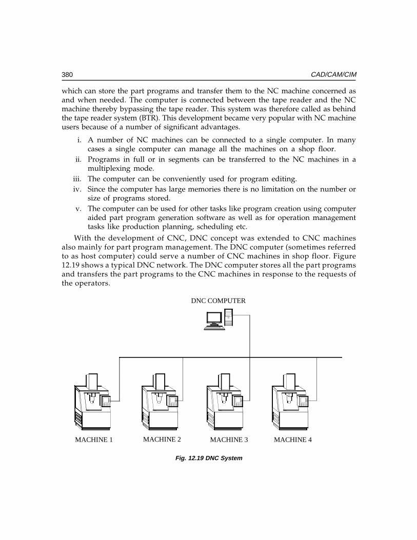
380 CAD/CAM/CIM
which can store the part programs and transfer them to the NC machine concerned asand when needed. The computer is connected between the tape reader and the NCmachine thereby bypassing the tape reader. This system was therefore called as behindthe tape reader system (BTR). This development became very popular with NC machineusers because of a number of significant advantages.
i. A number of NC machines can be connected to a single computer. In manycases a single computer can manage all the machines on a shop floor.
ii. Programs in full or in segments can be transferred to the NC machines in amultiplexing mode.
iii. The computer can be conveniently used for program editing.iv. Since the computer has large memories there is no limitation on the number or
size of programs stored.v. The computer can be used for other tasks like program creation using computer
aided part program generation software as well as for operation managementtasks like production planning, scheduling etc.
With the development of CNC, DNC concept was extended to CNC machinesalso mainly for part program management. The DNC computer (sometimes referredto as host computer) could serve a number of CNC machines in shop floor. Figure12.19 shows a typical DNC network. The DNC computer stores all the part programsand transfers the part programs to the CNC machines in response to the requests ofthe operators.
DNC COMPUTER
MACHINE 1 MACHINE 2 MACHINE 3 MACHINE 4
Fig. 12.19 DNC System
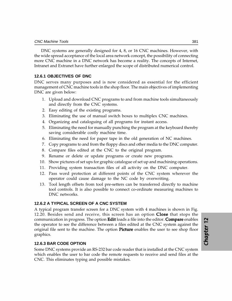
Ch
ap
ter
12C
ha
pte
r 12
Ch
ap
ter
12C
ha
pte
r 12
Ch
ap
ter
12
381CNC Machine Tools
DNC systems are generally designed for 4, 8, or 16 CNC machines. However, withthe wide spread acceptance of the local area network concept, the possibility of connectingmore CNC machine in a DNC network has become a reality. The concepts of Internet,Intranet and Extranet have further enlarged the scope of distributed numerical control.
12.6.1 OBJECTIVES OF DNCDNC serves many purposes and is now considered as essential for the efficientmanagement of CNC machine tools in the shop floor. The main objectives of implementingDNC are given below:
1. Upload and download CNC programs to and from machine tools simultaneouslyand directly from the CNC systems.
2. Easy editing of the existing programs.3. Eliminating the use of manual switch boxes to multiplex CNC machines.4. Organizing and cataloguing of all programs for instant access.5. Eliminating the need for manually punching the program at the keyboard thereby
saving considerable costly machine time.6. Eliminating the need for paper tape in the old generation of NC machines.7. Copy programs to and from the floppy discs and other media to the DNC computer.8. Compare files edited at the CNC to the original program.9. Rename or delete or update programs or create new programs.
10. Show pictures of set ups for graphic catalogue of set up and machining operations.11. Providing system transaction files of all activity on the DNC computer.12. Pass word protection at different points of the CNC system wherever the
operator could cause damage to the NC code by overwriting.13. Tool length offsets from tool pre-setters can be transferred directly to machine
tool controls. It is also possible to connect co-ordinate measuring machines toDNC networks.
12.6.2 A TYPICAL SCREEN OF A CNC SYSTEMA typical program transfer screen for a DNC system with 4 machines is shown in Fig.12.20. Besides send and receive, this screen has an option CloseCloseCloseCloseClose that stops thecommunication in progress. The option EditEditEditEditEdit loads a file into the editor. Compare Compare Compare Compare Compare enablesthe operator to see the difference between a files edited at the CNC system against theoriginal file sent to the machine. The option PicturePicturePicturePicturePicture enables the user to see shop floorgraphics.
12.6.3 BAR CODE OPTIONSome DNC systems provide an RS-232 bar code reader that is installed at the CNC systemwhich enables the user to bar code the remote requests to receive and send files at theCNC. This eliminates typing and possible mistakes.
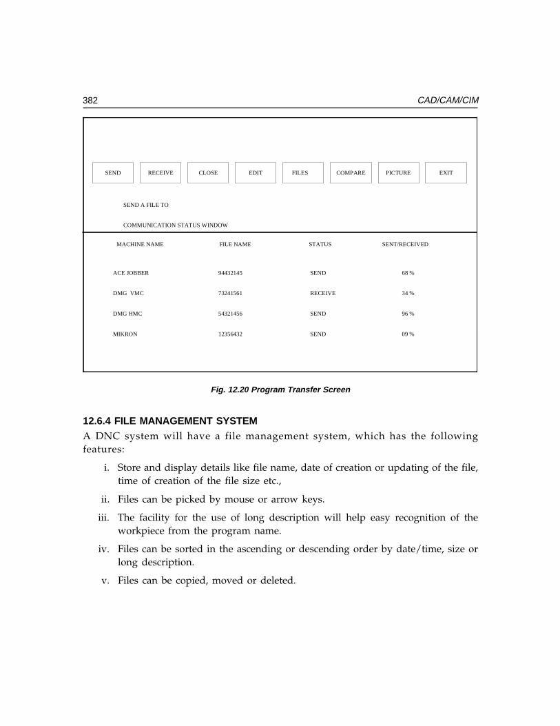
382 CAD/CAM/CIM
SEND RECEIVE CLOSE EDIT FILES COMPARE PICTURE EXIT
SEND A FILE TO
COMMUNICATION STATUS WINDOW
MACHINE NAME FILE NAME STATUS SENT/RECEIVED
ACE JOBBER
DMG VMC
DMG HMC
MIKRON
94432145
73241561
54321456
12356432
SEND
RECEIVE
SEND
SEND
68 %
34 %
96 %
09 %
Fig. 12.20 Program Transfer Screen
12.6.4 FILE MANAGEMENT SYSTEMA DNC system will have a file management system, which has the followingfeatures:
i. Store and display details like file name, date of creation or updating of the file,time of creation of the file size etc.,
ii. Files can be picked by mouse or arrow keys.
iii. The facility for the use of long description will help easy recognition of theworkpiece from the program name.
iv. Files can be sorted in the ascending or descending order by date/time, size orlong description.
v. Files can be copied, moved or deleted.
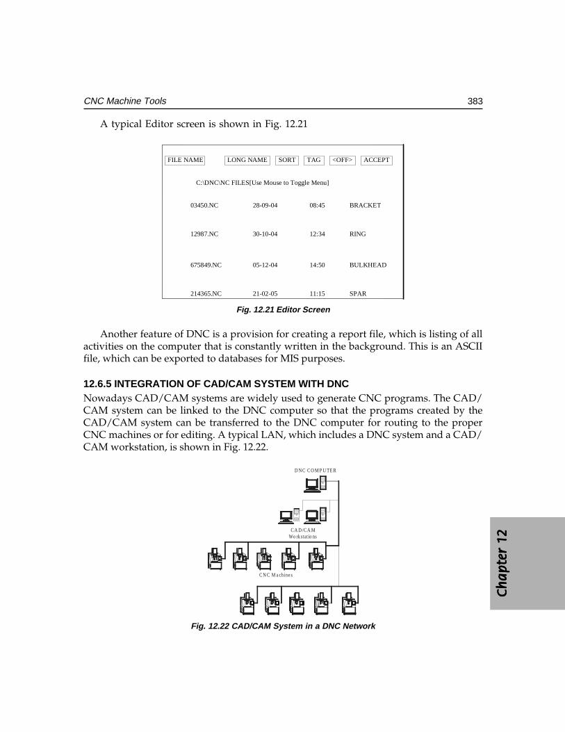
Ch
ap
ter
12C
ha
pte
r 12
Ch
ap
ter
12C
ha
pte
r 12
Ch
ap
ter
12
383CNC Machine Tools
A typical Editor screen is shown in Fig. 12.21
BRACKET
RING
BULKHEAD
SPAR
FILE NAME LONG NAME SORT TAG <OFF> ACCEPT
C:\DNC\NC FILES[Use Mouse to Toggle Menu]
03450.NC
12987.NC
675849.NC
214365.NC
28-09-04
30-10-04
05-12-04
21-02-05
08:45
12:34
14:50
11:15
Fig. 12.21 Editor Screen
Another feature of DNC is a provision for creating a report file, which is listing of allactivities on the computer that is constantly written in the background. This is an ASCIIfile, which can be exported to databases for MIS purposes.
12.6.5 INTEGRATION OF CAD/CAM SYSTEM WITH DNCNowadays CAD/CAM systems are widely used to generate CNC programs. The CAD/CAM system can be linked to the DNC computer so that the programs created by theCAD/CAM system can be transferred to the DNC computer for routing to the properCNC machines or for editing. A typical LAN, which includes a DNC system and a CAD/CAM workstation, is shown in Fig. 12.22.
D N C C O M P U TE R
C A D /C A MWo rk stat io ns
C N C M a chine s
Fig. 12.22 CAD/CAM System in a DNC Network
384 CAD/CAM/CIM
12.6.6 DISTRIBUTED NUMERICAL CONTROLSometimes the abbreviation DNC is used to denote distributed numerical control. Acomputer network for manufacturing may consist of a main frame computer, CAD/CAMwork stations, DNC host computer and the CNC systems connected to it. This configurationcan be beneficially used for NC data processing. Any complex calculations required forgenerating NC data can be transferred to the more powerful mainframe computer. Thusthe NC DATA processing is done at different hierarchical levels. In a way many of theDNC systems to day are in fact distributed processing systems.
12.6.7 FUNCTIONS OF A DNC SYSTEMThe functions of a DNC system can be summarized as below:
i. Part Program management: Part program stored in the hard disc can be routedto appropriate machines in the network depending upon the schedule.
ii. Shop floor editing: Program can be edited or modified to take into accountdesign changes, tool changes or machine changes.
iii. Shop floor graphics: The tool path simulation can be carried out on the shopfloor.
iv. Data collection: The DNC computer can be used for shop floor data collectionfor scheduling and monitoring.
v. Shop scheduling: Since NC program despatch is interlinked with the schedule,the DNC computer can be used for scheduling.
vi. Statistical Process Control (SPC): The SPC function can be integrated into theworking of the DNC computer as it can be interfaced with the shop floor datacollection function.
vii. Tool offset management: Tool offset data is sent to appropriate machine by thisfunction.
The DNC network systems are usually UNIX, Novell or Windows based. They havemultitasking capabilities and Ethernet, arcnet or token ring interfaces. They may also havelimited CAD/CAM capabilities. Efficient built-in security systems will take care ofunauthorized access.
12.7 FUNCTIONS AVAILABLE IN A TYPICAL CNC SYSTEM
The functions available in a popular CNC system are listed below:
(i) Controlled axes 2, 3, 4, 5 etc.(ii) Simultaneous axes 2, 3, 4, 5 etc.
(iii) Max. programmable dimensions 7 digits(iv) Linear Interpolation(v) Multi-quadrant circular Interpolation
Ch
ap
ter
12C
ha
pte
r 12
Ch
ap
ter
12C
ha
pte
r 12
Ch
ap
ter
12
385CNC Machine Tools
(vi) Thread cutting(vii) Rapid traverse
(viii) Feed rate override(ix) Rapid traverse override(x) Auto acceleration and retardation
(xi) Exact stop(xii) Dwell
(xiii) Reference point return(xiv) Co-ordinate system setting(xv) Decimal point input
(xvi) X axis dia./radius programming(xvii) Radius programming
(xviii) S, T, M codes(xix) Program number display(xx) Program number search
(xxi) Program/subprogram(xxii) Program format
(xxiii) Optional block skip(xxiv) Canned cycles(xxv) No. of offsets
(xxvi) Backlash compensation(xxvii) Cycle start/Feed hold(xxviii) Reset(xxix) Manual continuous feed(xxx) Incremental feed
(xxxi) Machine lock(xxxii) Dry run(xxxiii) Single block(xxxiv) Registerable programs(xxxv) Variable tape storage length(xxxvi) Data protect(xxxvii) Self diagnostics(xxxviii) Emergency stop(xxxix) Stored stop check
(XL) PMC (programmable machine control)(XLi) Spindle speed
( XLii) T N R C (Tool Nose Radius Compensation)( XLiii) Custom macros

386 CAD/CAM/CIM
(XLiv) Run Hour/Part display.
12.8 STANDARD CONTROLLERS
There are large number of manufacturers of CNC controllers. Some of those listed belowmay not be in production today.
(i) Acramatic(ii) Aciera CNC
(iii) AEG(iv) Allen Bradley(v) Anilam
(vi) ASEA(vii) Bendix
(viii) Bosch, 860, 880, alpha 2, alpha 3, CC 100, CC 200, CC 300, CC 330 Boschmicro 5Z, 8Z, PC (PG), system 5
(ix) Boehringer B1 T, B2 T(x) Charmilles Robofill
(xi) Cincinnati(xii) Deckel CNC 2301, contur, FP2-FP4
(xiii) DeVlieg(xiv) Dixi NC(xv) Emco-Turn
(xvi) ESAB NCE 301(xvii) FANUC, 0M, 0T, 3TF, 3M, 3TF 3T, 5M, 6MB, 6MA, 7M, 7T, 9, 10, 11, 12,
15, 20, 20A, 2000, 3000, MATE L, MATE M, MATE TS(xviii) Fidia
(xix) GE 550, 1050, 1050HL OX, 7542, CNC2000.(xx) Gildemeister EPL, EPM(UNI), EPM(ITY), EPM(SET), EPM II (BTR) 22
(xxi) Heidenhain TNC 135, 145, 151, 155, 355, 455(xxii) Heller Unipro 80
(xxiii) Hurco Ultimax B M C40(xxiv) Kongsberg NC 300, NC 2000(xxv) MAHO 432
(xxvi) Mandelli(xxvii) Mazak M1, M2, M32, T1, T2, T3, T4, T32
(xxviii) Meldas 5000(xxix) NUM 560, 750
Ch
ap
ter
12C
ha
pte
r 12
Ch
ap
ter
12C
ha
pte
r 12
Ch
ap
ter
12
387CNC Machine Tools
(xxx) Okuma OSP 330 D, OSP 2000, OSP3000, OSP5000(xxxi) Olivetti Contour
(xxxii) Philips 432, 3300, 3353, 6600, 6652.(xxxiii) Sinumerik Mate TG, PRIMO S, SPRINT T, SPRINT 3T, 3M, 5M, 5T, 6MA,
6TA, 6MB, 6TB, 7M, 7T, 520, 550C, 560K, 810, 820, 850(xxxiv) Traub TX 7,TX8,TX8D(xxxv) Toshiba
(xxxvi) Yasnac 3000 (xxxvii) Fagor
Fanuc, , , , , Sinumerik and GE-Fanuc are the most popular CNC system manufacturerstoday.
12.9 SOME OF THE FEATURES AVAILABLE IN TYPICAL HIGH END CNC SYSTEM
Recently a new generation of CNC controllers have been marketed by severalmanufacturers. Some of their important features are:
(i) Automatic determination of optimum tool path:Automatic determination of optimum tool path:Automatic determination of optimum tool path:Automatic determination of optimum tool path:Automatic determination of optimum tool path: By using data that is interactivelyinput to define the workpiece contours artificial intelligence is employed todetermine the optimum approach point and tool path to eliminate unnecessarytool movement. As a result, the overall machining cycle is minimized.
(ii) Feed spindle orientation: Feed spindle orientation: Feed spindle orientation: Feed spindle orientation: Feed spindle orientation: By the use of a digitally controlled AC spindle motor,spindle orientation is fast and precise.
(iii) Automatic feedrate override: Automatic feedrate override: Automatic feedrate override: Automatic feedrate override: Automatic feedrate override: Even though only one feedrate is programmed fora machining cycle such as a pocket milling, the optimum feedrate for both thein-feed direction and corner cutting is automatically determined. Also whenmilling pockets, the feedrate is automatically changed when machining with fullcutter width and when machining with partial cutter width to maintain theoptimum cutting conditions for the minimum machining time.
(iv) Simultaneous S, M and T functions: Simultaneous S, M and T functions: Simultaneous S, M and T functions: Simultaneous S, M and T functions: Simultaneous S, M and T functions: Simultaneous operation of different units,such as the ATC and Machine table indexing, A T C and pallet changer canperformed to greatly reduce machine’s non-cutting time.
(v) High speed tapping: High speed tapping: High speed tapping: High speed tapping: High speed tapping: The digitally controlled spindle motor allows spindle rotationand Z axis feed to be synchronized. This advanced design makes high speed, highprecision tapping possible without the use of the floating tap holder. This is alsoreferred as rigid tapping.
(vi) High speed cutting of complex contours:High speed cutting of complex contours:High speed cutting of complex contours:High speed cutting of complex contours:High speed cutting of complex contours: For complex contours that requireinterpolation by extremely small increments, the faster processing of speed of the32 or 64 bit processor results in a much higher vectorial feed rate than that ofconventional CNC systems.
388 CAD/CAM/CIM
(vii) D N C interface: D N C interface: D N C interface: D N C interface: D N C interface: The 32 or 64 bit CNC mounted on a machine can be linkedwith a host computer and transmit and receive data. By DNC interface,information can be shared.
(viii) MAP compatibility:MAP compatibility:MAP compatibility:MAP compatibility:MAP compatibility: The 32 bit CNC controllers is designed for MAP(Manufacturing Automation Protocol) compatibility - the internationalcommunication standards to be used by equipment in an automated factory.
(ix) Background communication: Background communication: Background communication: Background communication: Background communication: The high speed 32 bit microprocessors can handlecommunications of variety of data - programs, parameters, tool data andprograms with a host computer simultaneously while in automatic operation.
(x) Absolute position detection: Absolute position detection: Absolute position detection: Absolute position detection: Absolute position detection: If equipped with absolute position detection function,a machine does not have to return to the home position prior to beginningoperation. This is especially advantageous for a machining center controlled byhost computer.
(xi) Tool life management, Tool breakage detection and recovery:Tool life management, Tool breakage detection and recovery:Tool life management, Tool breakage detection and recovery:Tool life management, Tool breakage detection and recovery:Tool life management, Tool breakage detection and recovery: These functionsresident in the individual machine’s memory can be communicated with thehost computer, thereby facilitating centralized tool management.
(xii) Automatic centering: Automatic centering: Automatic centering: Automatic centering: Automatic centering: By the use of a touch sensor mounted in the spindle,measurement of datum holes and surfaces is performed. Based on themeasurement results, the work co-ordinate system is automatically shifted andmachining begins.
(xiii) Adaptive feed rate control: Adaptive feed rate control: Adaptive feed rate control: Adaptive feed rate control: Adaptive feed rate control: By continually monitoring the load on the spindlemotor and Z- axis servo motor, optimum cutting conditions are maintained.When an overload condition is detected, the programmed feedrate is automaticallyoverridden. As the cutting load becomes smaller, the feed rate will automaticallyreturn to the programmed value.
(xiv) Process management and program layout displays:Process management and program layout displays:Process management and program layout displays:Process management and program layout displays:Process management and program layout displays: The interconnections betweenprocesses and subprograms and processes with commonly used tools are indicatedon these displays for convenient program restarts.
(xv) Automatic tool length measurement: Automatic tool length measurement: Automatic tool length measurement: Automatic tool length measurement: Automatic tool length measurement: Tool length can be automatically measuredand registered in memory to greatly reduce tool setting time. One setting of themeasurement cycle allows up to 13 tools to automatically processed. (Thisprocess is semi-automatic for face mills and boring bars in that the tool mustfirst be manually positioned over the measurement unit).
(xvi) Workpiece co-ordinates: Workpiece co-ordinates: Workpiece co-ordinates: Workpiece co-ordinates: Workpiece co-ordinates: When using a tool (such as an edge finder) to establisha workpiece datum point, all that is required is to enter the tool radius. Thenecessary calculations are performed automatically to set the workpiece zeroposition. When the optional touch sensor is used the angular offset co-ordinatescan also be set. This allows high machining accuracy to be obtained even withsimple fixtures.
Ch
ap
ter
12C
ha
pte
r 12
Ch
ap
ter
12C
ha
pte
r 12
Ch
ap
ter
12
389CNC Machine Tools
(xvii) Tool path storage:Tool path storage:Tool path storage:Tool path storage:Tool path storage: The tool path storage function can be used to store in memorythe point where a tool breaks during the cutting plus the path used to retractthe cutter for servicing. This allows fast and smooth program restarting.
(xviii) Automatic cutting conditions editing: Automatic cutting conditions editing: Automatic cutting conditions editing: Automatic cutting conditions editing: Automatic cutting conditions editing: Programmed spindle speeds and feedrate are easily altered by override keys according to actual machining conditions.By pushing an appropriate key, the programmed cutting conditions areautomatically edited by the override amount on an individual tool basis.
(xix) Modal information display: Modal information display: Modal information display: Modal information display: Modal information display: The modal information display indicates which G,M, S, f codes are effective. This is extremely convenient for error-free restartof EIA / ISO programs.
(xx) Deflection compensation: Deflection compensation: Deflection compensation: Deflection compensation: Deflection compensation: Automatic compensation can be performed for thedisplacement at one axis in relation to another axis used as the datum.
(xxi) Large reduction of component parts:Large reduction of component parts:Large reduction of component parts:Large reduction of component parts:Large reduction of component parts: With a 32 or 64 bit microprocessor as thecore, large capacity memory chips, customs LSI’s and other state of the arttechnology used to the maximum, the number of parts is considerably smallerthen that of conventional CNC system resulting in a highly reliable and compactdesign.
(xxii) Ladder circuit display:Ladder circuit display:Ladder circuit display:Ladder circuit display:Ladder circuit display: The open and close status of individual circuits aredisplayed on the ladder chart on CRT display to help pinpoint the cause ofproblems.
(xxiii) Optimization of cutting conditions: Optimization of cutting conditions: Optimization of cutting conditions: Optimization of cutting conditions: Optimization of cutting conditions: Several CNC systems access cutting tooldatabases as well as cutting parameter databases. The interactive programmingfacilities enable the operator of the machine tool to input the features of thedrawing in the CNC system. The system responds with appropriate toolselection and cutting parameter selection. Techniques are also incorporatedto optimize the parameters.
12.10 GENERAL PROGRAMMING FEATURES OF CNC SYSTEMS
CNC systems can be classified into:
(i) CNC Systems for machining centres(ii) CNC Systems for lathes and turning Centres
(iii) CNC Systems for special applications like Grinding Machines, EDM, Electronbeam welding etc.
There are many features in these CNC systems which are of general interest andsome of them are discussed below:
Absolute and Incremental Programming:Absolute and Incremental Programming:Absolute and Incremental Programming:Absolute and Incremental Programming:Absolute and Incremental Programming: Figure 12.23 shows a plate in which 3 holesare to be drilled. The locations of the holes are indicated in the drawing of the component.For the purpose of programming, these dimensions should be specified with respect tothe workpiece coordinate system.
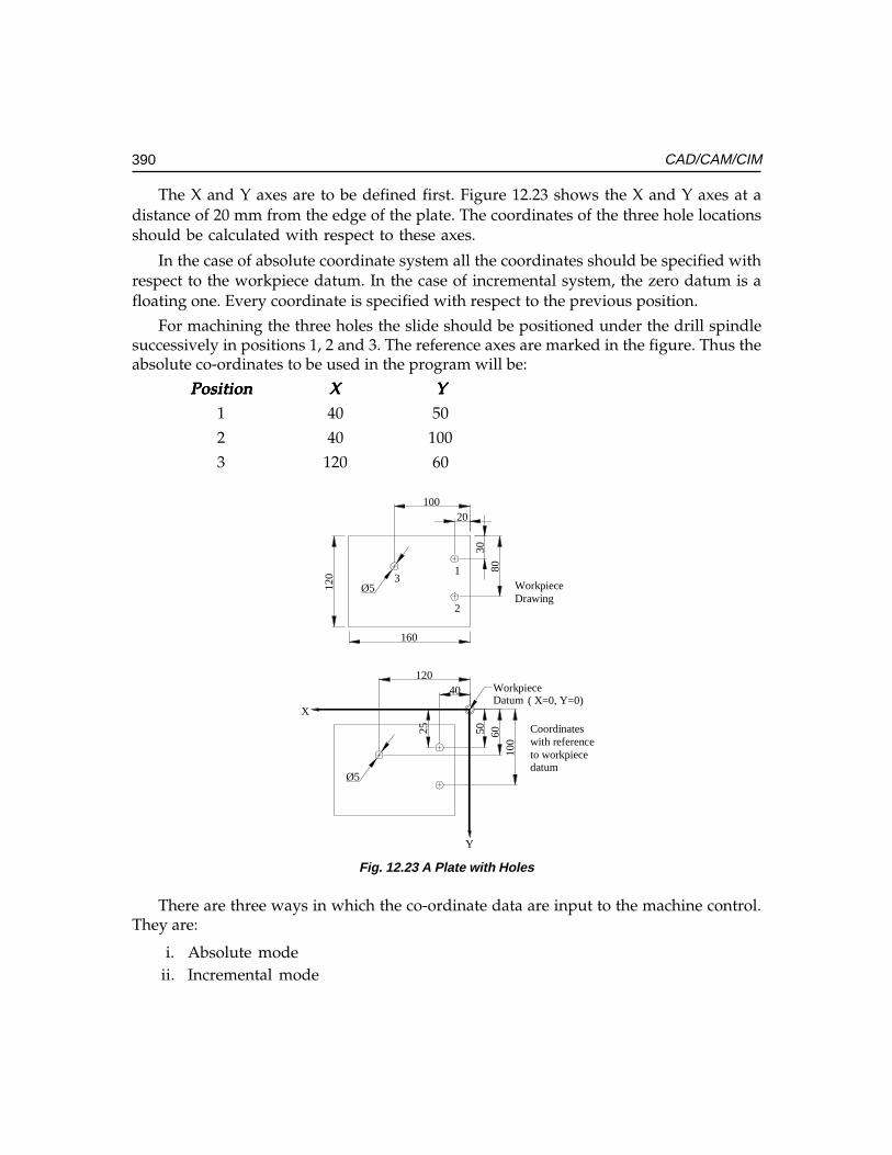
390 CAD/CAM/CIM
The X and Y axes are to be defined first. Figure 12.23 shows the X and Y axes at adistance of 20 mm from the edge of the plate. The coordinates of the three hole locationsshould be calculated with respect to these axes.
In the case of absolute coordinate system all the coordinates should be specified withrespect to the workpiece datum. In the case of incremental system, the zero datum is afloating one. Every coordinate is specified with respect to the previous position.
For machining the three holes the slide should be positioned under the drill spindlesuccessively in positions 1, 2 and 3. The reference axes are marked in the figure. Thus theabsolute co-ordinates to be used in the program will be:
PositionPositionPositionPositionPosition XXXXX YYYYY1 40 50
2 40 100
3 120 60
25
Ø5
Ø5
3080
20100
120
160
12040
100
6050
X
Y
1
2
3
WorkpieceDatum
WorkpieceDrawing
Coordinateswith referenceto workpiecedatum
( X=0, Y=0)
Fig. 12.23 A Plate with Holes
There are three ways in which the co-ordinate data are input to the machine control.They are:
i. Absolute modeii. Incremental mode
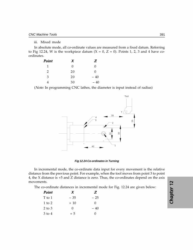
Ch
ap
ter
12C
ha
pte
r 12
Ch
ap
ter
12C
ha
pte
r 12
Ch
ap
ter
12
391CNC Machine Tools
iii. Mixed mode
In absolute mode, all co-ordinate values are measured from a fixed datum. Referringto Fig 12.24, W is the workpiece datum (X = 0, Z = 0). Points 1, 2, 3 and 4 have co-ordinates.
PointPointPointPointPoint XXXXX ZZZZZ1 0 0
2 20 0
3 20 – 40
4 30 – 40
(Note: In programming CNC lathes, the diameter is input instead of radius)
Fig 12.24 Co-ordinates in Turning
In incremental mode, the co-ordinate data input for every movement is the relativedistance from the previous point. For example, when the tool moves from point 3 to point4, the X distance is +5 and Z distance is zero. Thus, the co-ordinates depend on the axismovements.
The co-ordinate distances in incremental mode for Fig. 12.24 are given below:
PointPointPointPointPoint XXXXX ZZZZZT to 1 – 35 – 25
1 to 2 + 10 0
2 to 3 0 – 40
3 to 4 + 5 0
1
234
T20
40
Tool
35
30
25
392 CAD/CAM/CIM
In mixed mode, the co-ordinates can be either in absolute co-ordinates or incrementalco-ordinates. Absolute co-ordinates are labeled X and Z and incremental co-ordinates Uand W. For the example given, the co-ordinates can also be input as:
In mixed mode, the co-ordinates can be either in absolute co-ordinates or incrementalco-ordinates. Absolute co-ordinates are labeled X and Z and incremental co-ordinates Uand W. For the example given, the co-ordinates can also be input as:
PointPointPointPointPoint ZZZZZ ZZZZZ1 X0 Z02 U10 Z03 X20 W – 40
4 U+5 W0In lathes it is convenient to program in mixed mode whereas in the case of machining
centres program segments can be either in incremental or absolute mode or the wholeprogram can be in either one of the modes.
ii.ii.ii.ii.ii. Preparatory codes and miscellaneous codes:Preparatory codes and miscellaneous codes:Preparatory codes and miscellaneous codes:Preparatory codes and miscellaneous codes:Preparatory codes and miscellaneous codes:A typical line of a CNC program (called block) is given below:
N 0040N 0040N 0040N 0040N 0040 G01G01G01G01G01 X100.05X100.05X100.05X100.05X100.05 Y180.95 S450Y180.95 S450Y180.95 S450Y180.95 S450Y180.95 S450 M08;M08;M08;M08;M08;
Every block starts with a block number (3 or 4 digits), (N word); A block may haveone or more G functions. G- functions like G01 if defined earlier and if the value is thesame need not be repeated. For example, in a block if G01 is defined and if the next blockalso involves G01, this will be implied and need not be explicitly stated. Such G functionsare called modal G functions. The block may contain the X, Y and Z co-ordinates of thetarget point. The feed at which the slide movement is to be executed is specified in thefeed value. (e.g. F equal to 400 mm/min). If the feed is same as specified in the previousblock it need not be repeated again. The spindle speed is specified by the S address. (e.g.Speed is 450 rpm). The M word represents a miscellaneous function. In this case M08switches on the coolant motor. Thus each word has a unique alphabetic address. Hencethis type of formatting the program is referred to as word address format. Other commonlyused word addresses are T for tool, V for cutting speed, A for angle, etc.
G-codes or G functions are mainly NC functions. These are also called preparatoryfunctions. Some of these have been assigned standard functions and others are left to bedefined by the CNC system manufacturers. Common preparatory functions in a CNCsystem for lathes (FANUC 0) include:
(i) Interpolation functions• Positioning (G00)• Linear interpolation (G01)• Circular interpolation (G02, G03)• Polar co-ordinate interpolation (G112, G113)
• Cylindrical interpolation (G107)
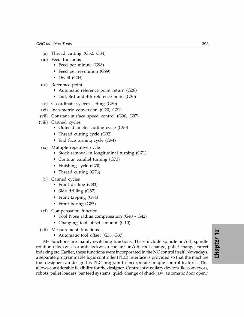
Ch
ap
ter
12C
ha
pte
r 12
Ch
ap
ter
12C
ha
pte
r 12
Ch
ap
ter
12
393CNC Machine Tools
(ii) Thread cutting (G32, G34)(iii) Feed functions
• Feed per minute (G98)• Feed per revolution (G99)• Dwell (G04)
(iv) Reference point• Automatic reference point return (G28)• 2nd, 3rd and 4th reference point (G30)
(v) Co-ordinate system setting (G50)(vi) Inch-metric conversion (G20, G21)
(vii) Constant surface speed control (G96, G97)(viii) Canned cycles
• Outer diameter cutting cycle (G90)• Thread cutting cycle (G92)• End face turning cycle (G94)
(ix) Multiple repetitive cycle• Stock removal in longitudinal turning (G71)• Contour parallel turning (G73)• Finishing cycle (G70)• Thread cutting (G76)
(x) Canned cycles• Front drilling (G83)• Side drilling (G87)• Front tapping (G84)• Front boring (G85)
(xi) Compensation function• Tool Nose radius compensation (G40 - G42)• Changing tool offset amount (G10)
(xii) Measurement functions• Automatic tool offset (G36, G37)
M- Functions are mainly switching functions. These include spindle on/off, spindlerotation (clockwise or anticlockwise) coolant on/off, tool change, pallet change, turretindexing etc. Earlier, these functions were incorporated in the NC control itself. Nowadays,a separate programmable logic controller (PLC) interface is provided so that the machinetool designer can design his PLC program to incorporate unique control features. Thisallows considerable flexibility for the designer. Control of auxiliary devices like conveyors,robots, pallet loaders, bar feed systems, quick change of chuck jaw, automatic door open/
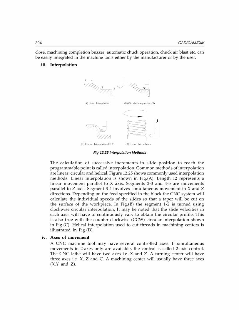
394 CAD/CAM/CIM
close, machining completion buzzer, automatic chuck operation, chuck air blast etc. canbe easily integrated in the machine tools either by the manufacturer or by the user.
iii.iii.iii.iii.iii. InterpolationInterpolationInterpolationInterpolationInterpolation
Fig 12.25 Interpolation Methods
The calculation of successive increments in slide position to reach theprogrammable point is called interpolation. Common methods of interpolationare linear, circular and helical. Figure 12.25 shows commonly used interpolationmethods. Linear interpolation is shown in Fig.(A). Length 12 represents alinear movement parallel to X axis. Segments 2-3 and 4-5 are movementsparallel to Z-axis. Segment 3-4 involves simultaneous movement in X and Zdirections. Depending on the feed specified in the block the CNC system willcalculate the individual speeds of the slides so that a taper will be cut onthe surface of the workpiece. In Fig.(B) the segment 1-2 is turned usingclockwise circular interpolation. It may be noted that the slide velocities ineach axes will have to continuously vary to obtain the circular profile. Thisis also true with the counter clockwise (CCW) circular interpolation shownin Fig.(C). Helical interpolation used to cut threads in machining centers isillustrated in Fig.(D).
iv.iv.iv.iv.iv. Axes of movementAxes of movementAxes of movementAxes of movementAxes of movementA CNC machine tool may have several controlled axes. If simultaneousmovements in 2-axes only are available, the control is called 2-axis control.The CNC lathe will have two axes i.e. X and Z. A turning center will havethree axes i.e. X, Z and C. A machining center will usually have three axes(X,Y and Z).
1
23
45
1
2
1
2
(A ) L in ea r In te rpo lat io n (B ) C irc u la r In te rp o la t io n -C W
(C ) C irc u la r In te rp o la t io n -C C W (D ) H el ica l In te rpo la t io n
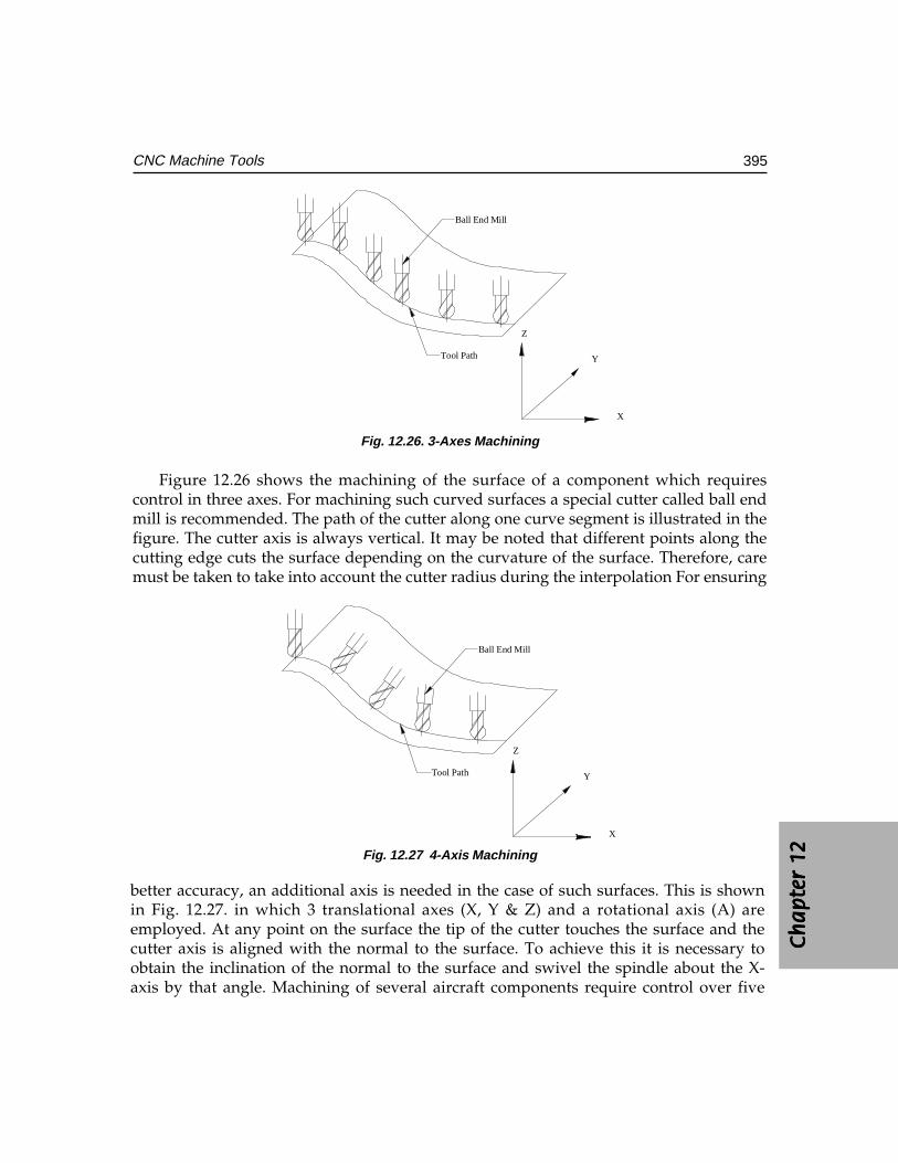
Ch
ap
ter
12C
ha
pte
r 12
Ch
ap
ter
12C
ha
pte
r 12
Ch
ap
ter
12
395CNC Machine Tools
Tool Path
X
Y
Z
Ball End Mill
Fig. 12.26. 3-Axes Machining
Figure 12.26 shows the machining of the surface of a component which requirescontrol in three axes. For machining such curved surfaces a special cutter called ball endmill is recommended. The path of the cutter along one curve segment is illustrated in thefigure. The cutter axis is always vertical. It may be noted that different points along thecutting edge cuts the surface depending on the curvature of the surface. Therefore, caremust be taken to take into account the cutter radius during the interpolation For ensuring
better accuracy, an additional axis is needed in the case of such surfaces. This is shownin Fig. 12.27. in which 3 translational axes (X, Y & Z) and a rotational axis (A) areemployed. At any point on the surface the tip of the cutter touches the surface and thecutter axis is aligned with the normal to the surface. To achieve this it is necessary toobtain the inclination of the normal to the surface and swivel the spindle about the X-axis by that angle. Machining of several aircraft components require control over five
Tool Path
X
Y
Z
Ball End Mill
Fig. 12.27 4-Axis Machining
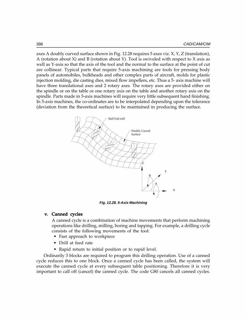
396 CAD/CAM/CIM
axes A doubly curved surface shown in Fig. 12.28 requires 5 axes viz. X, Y, Z (translation),A (rotation about X) and B (rotation about Y). Tool is swiveled with respect to X axis aswell as Y-axis so that the axis of the tool and the normal to the surface at the point of cutare collinear. Typical parts that require 5-axis machining are tools for pressing bodypanels of automobiles, bulkheads and other complex parts of aircraft, molds for plasticinjection molding, die casting dies, mixed flow impellers, etc. Thus a 5- axis machine willhave three translational axes and 2 rotary axes. The rotary axes are provided either onthe spindle or on the table or one rotary axis on the table and another rotary axis on thespindle. Parts made in 5-axis machines will require very little subsequent hand finishing.In 5-axis machines, the co-ordinates are to be interpolated depending upon the tolerance(deviation from the theoretical surface) to be maintained in producing the surface.
Ball End mill
Doubly CurvedSurface
B
A
X
Y
Z
Fig. 12.28. 5-Axis Machining
v.v.v.v.v. Canned cyclesCanned cyclesCanned cyclesCanned cyclesCanned cyclesA canned cycle is a combination of machine movements that perform machiningoperations like drilling, milling, boring and tapping. For example, a drilling cycleconsists of the following movements of the tool:• Fast approach to workpiece• Drill at feed rate• Rapid return to initial position or to rapid level.
Ordinarily 3 blocks are required to program this drilling operation. Use of a cannedcycle reduces this to one block. Once a canned cycle has been called, the system willexecute the canned cycle at every subsequent table positioning. Therefore it is veryimportant to call off (cancel) the canned cycle. The code G80 cancels all canned cycles.
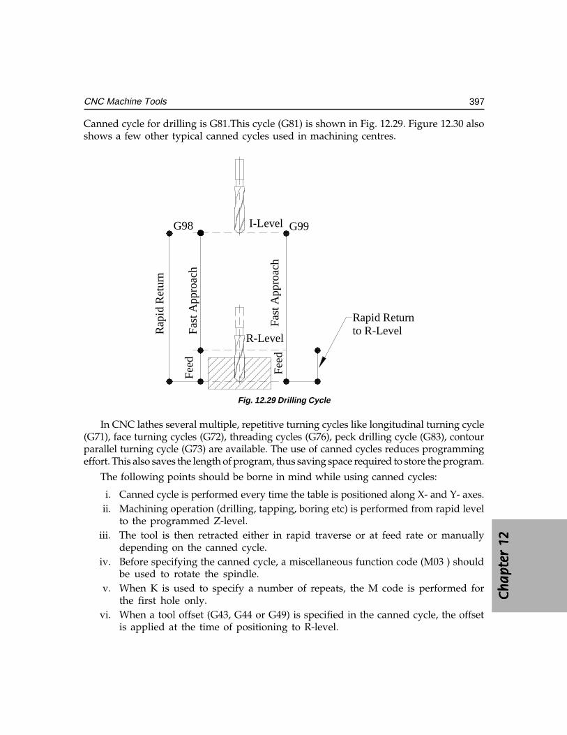
Ch
ap
ter
12C
ha
pte
r 12
Ch
ap
ter
12C
ha
pte
r 12
Ch
ap
ter
12
397CNC Machine Tools
Canned cycle for drilling is G81.This cycle (G81) is shown in Fig. 12.29. Figure 12.30 alsoshows a few other typical canned cycles used in machining centres.
Fast
App
roac
h
Rap
id R
etur
n
Fast
App
roac
h
Feed
Feed
Rapid Returnto R-Level
I-Level
R-Level
G98 G99
Fig. 12.29 Drilling Cycle
In CNC lathes several multiple, repetitive turning cycles like longitudinal turning cycle(G71), face turning cycles (G72), threading cycles (G76), peck drilling cycle (G83), contourparallel turning cycle (G73) are available. The use of canned cycles reduces programmingeffort. This also saves the length of program, thus saving space required to store the program.
The following points should be borne in mind while using canned cycles:
i. Canned cycle is performed every time the table is positioned along X- and Y- axes.ii. Machining operation (drilling, tapping, boring etc) is performed from rapid level
to the programmed Z-level.iii. The tool is then retracted either in rapid traverse or at feed rate or manually
depending on the canned cycle.iv. Before specifying the canned cycle, a miscellaneous function code (M03 ) should
be used to rotate the spindle.v. When K is used to specify a number of repeats, the M code is performed for
the first hole only.vi. When a tool offset (G43, G44 or G49) is specified in the canned cycle, the offset
is applied at the time of positioning to R-level.
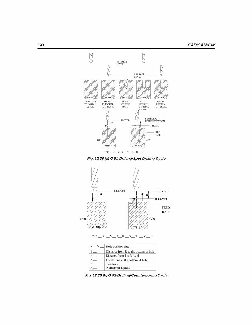
398 CAD/CAM/CIM
WORK WORK WORK WORK WORK
APPROACHTO INITIAL
LEVEL
RAPIDTRAVERSE
TO R-LEVEL
DRILLAT FEED
RATE
RAPIDRETURN
TO INITIALLEVEL
RAPIDRETURN
TO R-LEVEL
INITIAL(I)LEVEL
RAPIDLEVEL
(R)
TRAVERSERAPID
WORK
WORK
I-LEVEL
WORK
R-LEVEL
SYMBOLICREPRESENTATION
FEEDRAPID
G81 X Y Z R F K ;
G98 G99
Fig. 12.30 (a) G 81-Drilling/Spot Drilling Cycle
WORK
I-LEVEL
WORK
R-LEVEL
FEEDRAPID
G98 G99
G82 X Y Z R P F K ;
X Y
ZR
PFK
Hole position data
Distance from I to R level
Dwell time at the bottom of holeFeed rateNumber of repeats
Distance from R to the bottom of hole
I-LEVEL
R
Z
Fig. 12.30 (b) G 82-Drilling/Counterboring Cycle
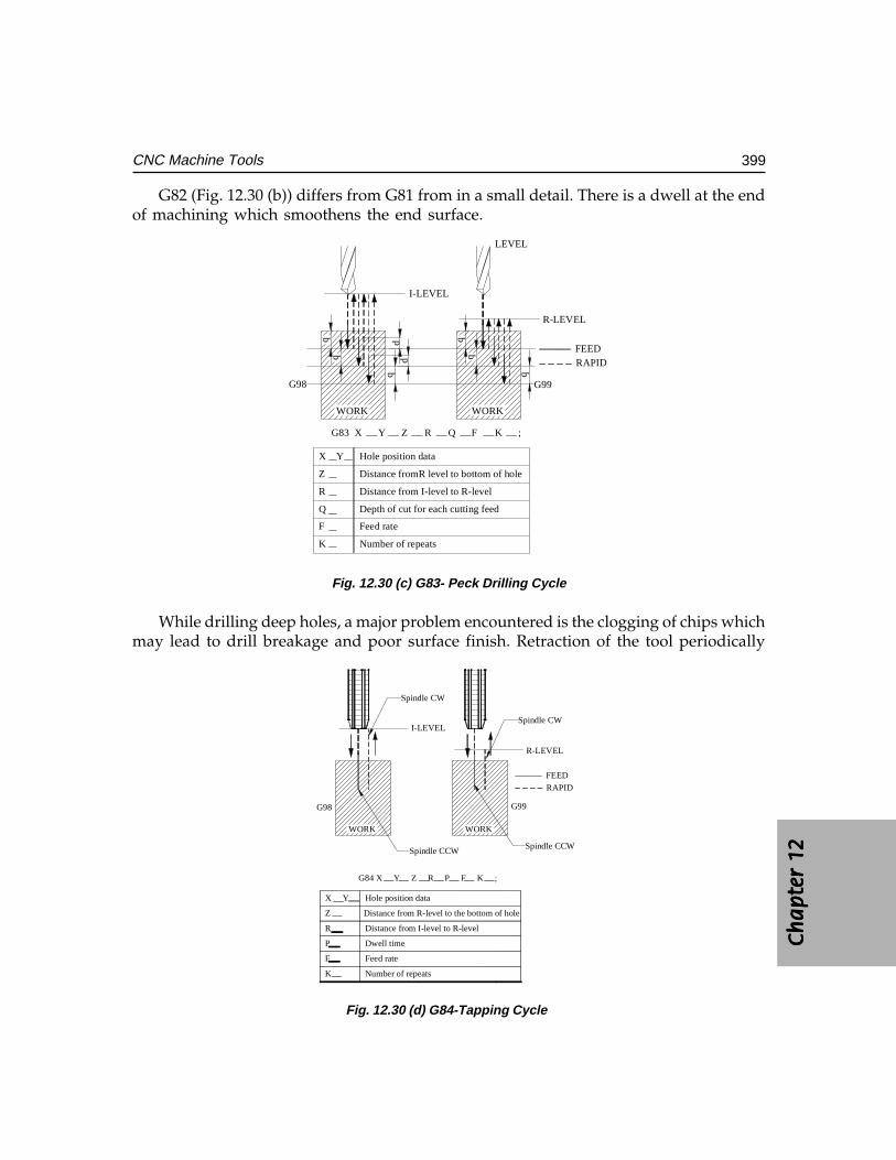
Ch
ap
ter
12C
ha
pte
r 12
Ch
ap
ter
12C
ha
pte
r 12
Ch
ap
ter
12
399CNC Machine Tools
G82 (Fig. 12.30 (b)) differs from G81 from in a small detail. There is a dwell at the endof machining which smoothens the end surface.
LEVEL
WORK
I-LEVEL
WORK
R-LEVEL
FEEDRAPID
G98 G99
q
q
dd
X Y
Z
R
Q
F
K
Hole position data
Distance fromR level to bottom of hole
Distance from I-level to R-level
Depth of cut for each cutting feed
Feed rate
Number of repeats
G83 X Y Z R Q F K ;
Fig. 12.30 (c) G83- Peck Drilling Cycle
While drilling deep holes, a major problem encountered is the clogging of chips whichmay lead to drill breakage and poor surface finish. Retraction of the tool periodically
WORK
I-LEVEL
WORK
R-LEVEL
FEED
RAPID
G98 G99
Spindle CCW
Spindle CW
Spindle CW
Spindle CCW
G84 X Y Z R P F K ;
X Y
Z
R
P
F
K
Hole position data
Distance from I-level to R-level
Dwell time
Feed rate
Number of repeats
Distance from R-level to the bottom of hole
Fig. 12.30 (d) G84-Tapping Cycle
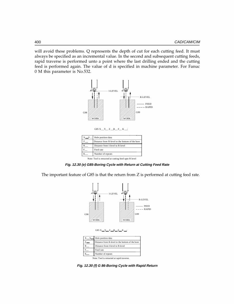
400 CAD/CAM/CIM
will avoid these problems. Q represents the depth of cut for each cutting feed. It mustalways be specified as an incremental value. In the second and subsequent cutting feeds,rapid traverse is performed unto a point where the last drilling ended and the cuttingfeed is performed again. The value of d is specified in machine parameter. For Fanuc0 M this parameter is No.532.
WORK
I-LEVEL
WORK
R-LEVEL
FEEDRAPID
G98 G99
X Y
Z
R
F
K
Hole position data
Distance from I-level to R-level
Feed rate
Number of repeats
G85 X Y Z R F K ;
Distance from R-level to the bottom of the bore
Note: Tool is retracted at cutting feed upto R level
Fig. 12.30 (e) G85-Boring Cycle with Return at Cutting Feed Rate
The important feature of G85 is that the return from Z is performed at cutting feed rate.
WORK
I-LEVEL
WORK
R-LEVEL
FEEDRAPID
G98 G99
X Y
Z
R
F
K
Hole position data
Distance from I-level to R-level
Feed rate
Number of repeats
G85 X Y Z R F K ;
Distance from R-level to the bottom of the bore
Note: Tool is retracted at rapid traverse.
Fig. 12.30 (f) G 86-Boring Cycle with Rapid Return
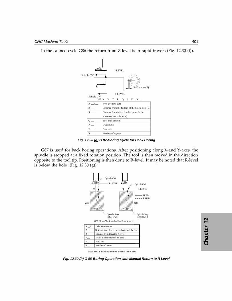
Ch
ap
ter
12C
ha
pte
r 12
Ch
ap
ter
12C
ha
pte
r 12
Ch
ap
ter
12
401CNC Machine Tools
In the canned cycle G86 the return from Z level is in rapid travers (Fig. 12.30 (f)).
I-LEVEL
Shift amount Q
R-LEVEL
G87 X Y Z R Q P F K ;
X Y
Z
R
Q
P
F
K
Hole position data
Distance from the bottom of the holeto point Z
Distance from initial level to point R( the
bottom of the hole level)
Tool shift amount
Dwell time
Feed rate
Number of repeats
Spindle CW
Spindle CW
Fig. 12.30 (g) G 87-Boring Cycle for Back Boring
G87 is used for back boring operations. After positioning along X-and Y-axes, thespindle is stopped at a fixed rotation position. The tool is then moved in the directionopposite to the tool tip. Positioning is then done to R-level. It may be noted that R-levelis below the hole (Fig. 12.30 (g)).
R
F
K
Hole position data
Distance from I-level to R-level
Feed rate
Number of repeats
Distance from R-level to the bottom of the bore
Spindle StopAfter Dwell
Spindle StopAfter Dwell
Spindle CW
Spindle CW
G86 X Y Z R P F K ;
P Dwell at the bottom of the bore
Note: Tool is manually retracted either to I or R level.
WORK
I-LEVEL
WORK
R-LEVEL
FEEDRAPID
G98 G99
X Y
Z
Fig. 12.30 (h) G 88-Boring Operation with Manual Return to R Level
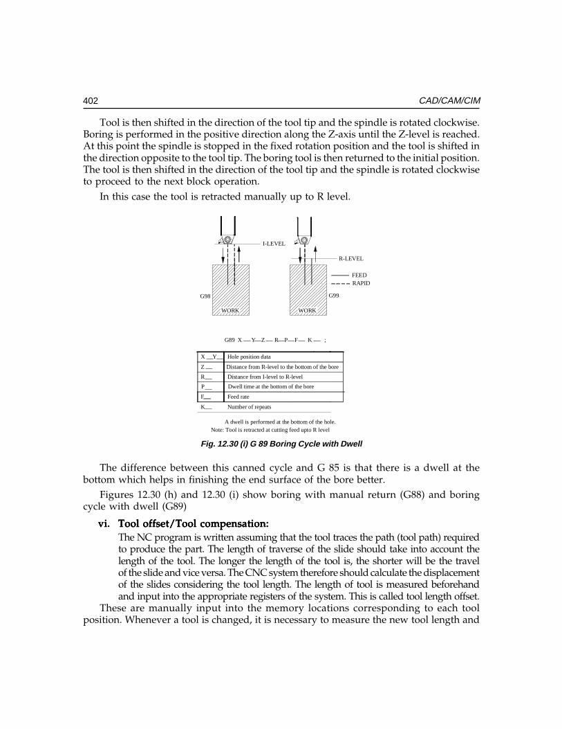
402 CAD/CAM/CIM
Tool is then shifted in the direction of the tool tip and the spindle is rotated clockwise.Boring is performed in the positive direction along the Z-axis until the Z-level is reached.At this point the spindle is stopped in the fixed rotation position and the tool is shifted inthe direction opposite to the tool tip. The boring tool is then returned to the initial position.The tool is then shifted in the direction of the tool tip and the spindle is rotated clockwiseto proceed to the next block operation.
In this case the tool is retracted manually up to R level.
R
F
K
Hole position data
Distance from I-level to R-level
Feed rate
Number of repeats
Distance from R-level to the bottom of the bore
Note: Tool is retracted at cutting feed upto R level
P Dwell time at the bottom of the bore
G89 X Y Z R P F K ;
A dwell is performed at the bottom of the hole.
WORK
I-LEVEL
WORK
R-LEVEL
FEEDRAPID
G98 G99
X Y
Z
Fig. 12.30 (i) G 89 Boring Cycle with Dwell
The difference between this canned cycle and G 85 is that there is a dwell at thebottom which helps in finishing the end surface of the bore better.
Figures 12.30 (h) and 12.30 (i) show boring with manual return (G88) and boringcycle with dwell (G89)
vi.vi.vi.vi.vi. Tool offset/Tool compensation:Tool offset/Tool compensation:Tool offset/Tool compensation:Tool offset/Tool compensation:Tool offset/Tool compensation:The NC program is written assuming that the tool traces the path (tool path) requiredto produce the part. The length of traverse of the slide should take into account thelength of the tool. The longer the length of the tool is, the shorter will be the travelof the slide and vice versa. The CNC system therefore should calculate the displacementof the slides considering the tool length. The length of tool is measured beforehandand input into the appropriate registers of the system. This is called tool length offset.
These are manually input into the memory locations corresponding to each toolposition. Whenever a tool is changed, it is necessary to measure the new tool length and
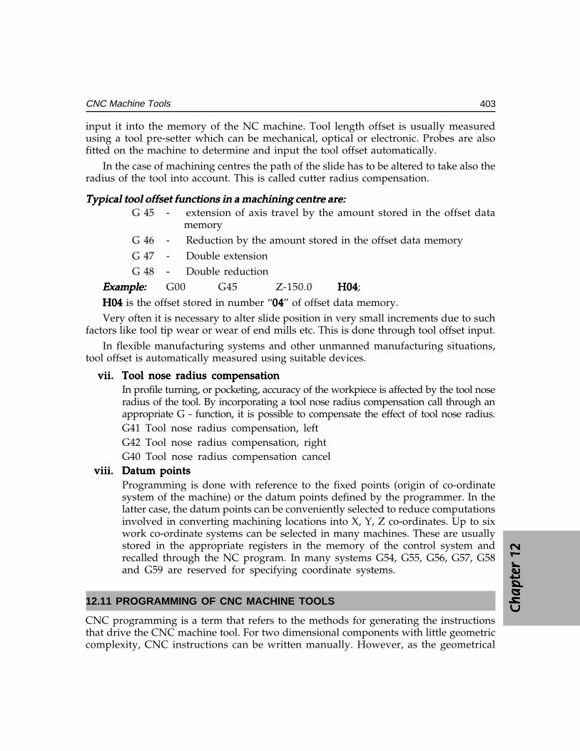
Ch
ap
ter
12C
ha
pte
r 12
Ch
ap
ter
12C
ha
pte
r 12
Ch
ap
ter
12
403CNC Machine Tools
input it into the memory of the NC machine. Tool length offset is usually measuredusing a tool pre-setter which can be mechanical, optical or electronic. Probes are alsofitted on the machine to determine and input the tool offset automatically.
In the case of machining centres the path of the slide has to be altered to take also theradius of the tool into account. This is called cutter radius compensation.
Typical tool offset functions in a machining centre are:Typical tool offset functions in a machining centre are:Typical tool offset functions in a machining centre are:Typical tool offset functions in a machining centre are:Typical tool offset functions in a machining centre are:G 45 - extension of axis travel by the amount stored in the offset data
memoryG 46 - Reduction by the amount stored in the offset data memoryG 47 - Double extensionG 48 - Double reduction
Example:Example:Example:Example:Example: G00 G45 Z-150.0 H04H04H04H04H04;
H04H04H04H04H04 is the offset stored in number “0404040404” of offset data memory.Very often it is necessary to alter slide position in very small increments due to such
factors like tool tip wear or wear of end mills etc. This is done through tool offset input.In flexible manufacturing systems and other unmanned manufacturing situations,
tool offset is automatically measured using suitable devices.
vii.vii.vii.vii.vii. Tool nose radius compensationTool nose radius compensationTool nose radius compensationTool nose radius compensationTool nose radius compensationIn profile turning, or pocketing, accuracy of the workpiece is affected by the tool noseradius of the tool. By incorporating a tool nose radius compensation call through anappropriate G - function, it is possible to compensate the effect of tool nose radius.G41 Tool nose radius compensation, leftG42 Tool nose radius compensation, rightG40 Tool nose radius compensation cancel
viii.viii.viii.viii.viii. Datum pointsDatum pointsDatum pointsDatum pointsDatum pointsProgramming is done with reference to the fixed points (origin of co-ordinatesystem of the machine) or the datum points defined by the programmer. In thelatter case, the datum points can be conveniently selected to reduce computationsinvolved in converting machining locations into X, Y, Z co-ordinates. Up to sixwork co-ordinate systems can be selected in many machines. These are usuallystored in the appropriate registers in the memory of the control system andrecalled through the NC program. In many systems G54, G55, G56, G57, G58and G59 are reserved for specifying coordinate systems.
12.11 PROGRAMMING OF CNC MACHINE TOOLS
CNC programming is a term that refers to the methods for generating the instructionsthat drive the CNC machine tool. For two dimensional components with little geometriccomplexity, CNC instructions can be written manually. However, as the geometrical
404 CAD/CAM/CIM
complexity increases more sophisticated techniques are required, particularly for 3-axis,4-axis and 5-axis CNC machining.
There are three distinct techniques adopted for creating CNC programs:
i. Manual CNC Programmingii. Programming using CAM software (CAD/CAM based programming systems)
Manual programming is recommended for simple workpieces which require only afew blocks of program. Programming of complex workpieces requires the help of a CAMsoftware. CAD/CAM based systems have become popular recently and are now beingwidely adopted. Detailed description of these techniques is given in the following section.
12.11.1 MANUAL PART PROGRAMMINGThis technique is widely used for workpieces of relatively simple geometry. The steps inmanual programming are:
i. Careful study of component drawing- materials, tolerances, surface finish etcii. Select the raw material or blank if not specified.
iii. Select the number of set ups necessary and the machine/s on which the part ismachined.
iv. Deciding the workpiece datum for each set up.v. Designing the fixtures or holding of the job.
vi. Deciding the process and sequence of processes to achieve the desired accuracyand tolerances
vii. Selecting the tools and cutting parameters.viii. Writing the program
ix. Input the program and dry run; correct mistakes if any.x. Produce the first part and inspect.
xi. Correct the program if necessary and progress to lot production.xii. Create documentation for future reference.
xiii. Archive the program and documentation.
It was mentioned earlier that an NC program will consist of a number of lines called blocks.Each block will consist of a number of words. Each word will have two components: a wordaddress and a numeric code representing information. The common word addresses are:
N - G - X - Y - Z - A - B - C - F - S - T - M
where
N = sequence number of instructions
G = preparatory function
XYZABC = co-ordinate and angular data
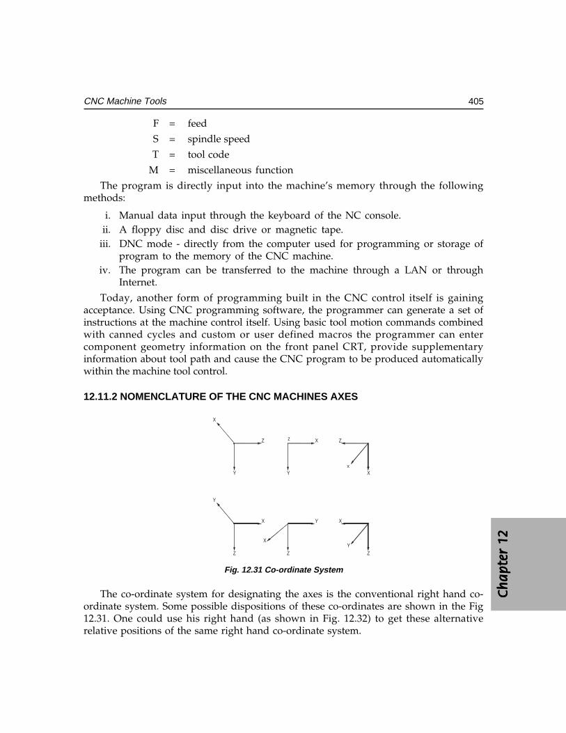
Ch
ap
ter
12C
ha
pte
r 12
Ch
ap
ter
12C
ha
pte
r 12
Ch
ap
ter
12
405CNC Machine Tools
F = feed
S = spindle speed
T = tool code
M = miscellaneous function
The program is directly input into the machine’s memory through the followingmethods:
i. Manual data input through the keyboard of the NC console.ii. A floppy disc and disc drive or magnetic tape.
iii. DNC mode - directly from the computer used for programming or storage ofprogram to the memory of the CNC machine.
iv. The program can be transferred to the machine through a LAN or throughInternet.
Today, another form of programming built in the CNC control itself is gainingacceptance. Using CNC programming software, the programmer can generate a set ofinstructions at the machine control itself. Using basic tool motion commands combinedwith canned cycles and custom or user defined macros the programmer can entercomponent geometry information on the front panel CRT, provide supplementaryinformation about tool path and cause the CNC program to be produced automaticallywithin the machine tool control.
12.11.2 NOMENCLATURE OF THE CNC MACHINES AXES
Y
X
Z
Y
X
Z
Z
Y
Y
X
X
Z
X
ZY
X
z
Fig. 12.31 Co-ordinate System
The co-ordinate system for designating the axes is the conventional right hand co-ordinate system. Some possible dispositions of these co-ordinates are shown in the Fig12.31. One could use his right hand (as shown in Fig. 12.32) to get these alternativerelative positions of the same right hand co-ordinate system.
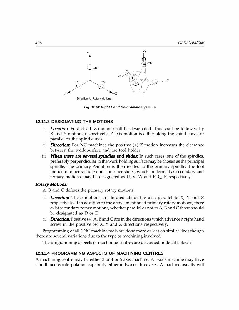
406 CAD/CAM/CIM
Fig. 12.32 Right Hand Co-ordinate Systems
12.11.3 DESIGNATING THE MOTIONS
i. LocationLocationLocationLocationLocation::::: First of all, Z-motion shall be designated. This shall be followed byX and Y motions respectively. Z-axis motion is either along the spindle axis orparallel to the spindle axis.
ii. DirectionDirectionDirectionDirectionDirection::::: For NC machines the positive (+) Z-motion increases the clearancebetween the work surface and the tool holder.
iii. When there are several spindles and slidesWhen there are several spindles and slidesWhen there are several spindles and slidesWhen there are several spindles and slidesWhen there are several spindles and slides::::: In such cases, one of the spindles,preferably perpendicular to the work holding surface may be chosen as the principalspindle. The primary Z-motion is then related to the primary spindle. The toolmotion of other spindle quills or other slides, which are termed as secondary andtertiary motions, may be designated as U, V, W and P, Q, R respectively.
Rotary Motions:Rotary Motions:Rotary Motions:Rotary Motions:Rotary Motions:A, B and C defines the primary rotary motions.
i. Location: Location: Location: Location: Location: These motions are located about the axis parallel to X, Y and Zrespectively. If in addition to the above mentioned primary rotary motions, thereexist secondary rotary motions, whether parallel or not to A, B and C those shouldbe designated as D or E.
ii. Direction:Direction:Direction:Direction:Direction: Positive (+) A, B and C are in the directions which advance a right handscrew in the positive (+) X, Y and Z directions respectively.
Programming of all CNC machine tools are done more or less on similar lines thoughthere are several variations due to the type of machining involved.
The programming aspects of machining centres are discussed in detail below :
12.11.4 PROGRAMMING ASPECTS OF MACHINING CENTRESA machining centre may be either 3 or 4 or 5 axis machine. A 3-axis machine may havesimultaneous interpolation capability either in two or three axes. A machine usually will
+C
+Y
+Z +X
+A
Direction for Rotary Motions
+B
+X
+A
+Y
+Z
+C
+B
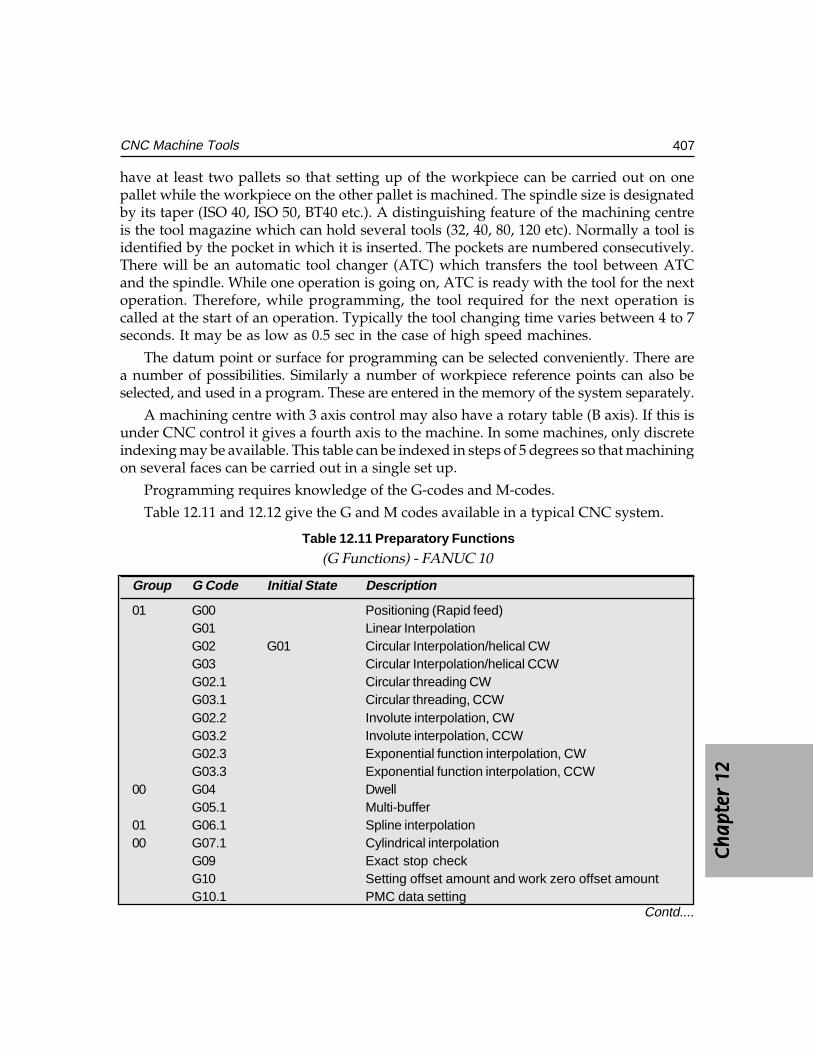
Ch
ap
ter
12C
ha
pte
r 12
Ch
ap
ter
12C
ha
pte
r 12
Ch
ap
ter
12
407CNC Machine Tools
have at least two pallets so that setting up of the workpiece can be carried out on onepallet while the workpiece on the other pallet is machined. The spindle size is designatedby its taper (ISO 40, ISO 50, BT40 etc.). A distinguishing feature of the machining centreis the tool magazine which can hold several tools (32, 40, 80, 120 etc). Normally a tool isidentified by the pocket in which it is inserted. The pockets are numbered consecutively.There will be an automatic tool changer (ATC) which transfers the tool between ATCand the spindle. While one operation is going on, ATC is ready with the tool for the nextoperation. Therefore, while programming, the tool required for the next operation iscalled at the start of an operation. Typically the tool changing time varies between 4 to 7seconds. It may be as low as 0.5 sec in the case of high speed machines.
The datum point or surface for programming can be selected conveniently. There area number of possibilities. Similarly a number of workpiece reference points can also beselected, and used in a program. These are entered in the memory of the system separately.
A machining centre with 3 axis control may also have a rotary table (B axis). If this isunder CNC control it gives a fourth axis to the machine. In some machines, only discreteindexing may be available. This table can be indexed in steps of 5 degrees so that machiningon several faces can be carried out in a single set up.
Programming requires knowledge of the G-codes and M-codes.
Table 12.11 and 12.12 give the G and M codes available in a typical CNC system.
Table 12.11 Preparatory Functions
(G Functions) - FANUC 10
Group G Code Initial State Description
01 G00 Positioning (Rapid feed)G01 Linear InterpolationG02 G01 Circular Interpolation/helical CWG03 Circular Interpolation/helical CCWG02.1 Circular threading CWG03.1 Circular threading, CCWG02.2 Involute interpolation, CWG03.2 Involute interpolation, CCWG02.3 Exponential function interpolation, CWG03.3 Exponential function interpolation, CCW
00 G04 DwellG05.1 Multi-buffer
01 G06.1 Spline interpolation00 G07.1 Cylindrical interpolation
G09 Exact stop checkG10 Setting offset amount and work zero offset amountG10.1 PMC data setting
Contd....
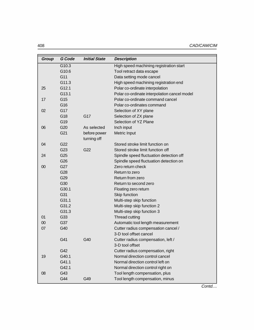
408 CAD/CAM/CIM
Group G Code Initial State Description
G10.3 High speed machining registration startG10.6 Tool retract data escapeG11 Data setting mode cancelG11.3 High speed machining registration end
25 G12.1 Polar co-ordinate interpolationG13.1 Polar co-ordinate interpolation cancel model
17 G15 Polar co-ordinate command cancelG16 Polar co-ordinates command
02 G17 Selection of XY planeG18 G17 Selection of ZX planeG19 Selection of YZ Plane
06 G20 As selected Inch inputG21 before power Metric Input
turning off04 G22 Stored stroke limit function on
G23 G22 Stored stroke limit function off24 G25 Spindle speed fluctuation detection off
G26 Spindle speed fluctuation detection on00 G27 Zero return check
G28 Return to zeroG29 Return from zeroG30 Return to second zeroG30.1 Floating zero returnG31 Skip functionG31.1 Multi-step skip functionG31.2 Multi-step skip function 2G31.3 Multi-step skip function 3
01 G33 Thread cutting00 G37 Automatic tool length measurement07 G40 Cutter radius compensation cancel /
3-D tool offset cancelG41 G40 Cutter radius compensation, left /
3-D tool offsetG42 Cutter radius compensation, right
19 G40.1 Normal direction control cancelG41.1 Normal direction control left onG42.1 Normal direction control right on
08 G43 Tool length compensation, plusG44 G49 Tool length compensation, minus
Contd....
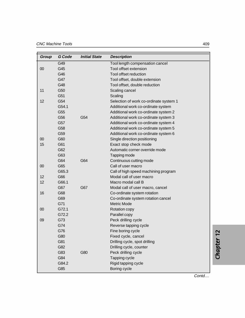
Ch
ap
ter
12C
ha
pte
r 12
Ch
ap
ter
12C
ha
pte
r 12
Ch
ap
ter
12
409CNC Machine Tools
Group G Code Initial State Description
G49 Tool length compensation cancel00 G45 Tool offset extension
G46 Tool offset reductionG47 Tool offset, double extensionG48 Tool offset, double reduction
11 G50 Scaling cancelG51 Scaling
12 G54 Selection of work co-ordinate system 1G54.1 Additional work co-ordinate systemG55 Additional work co-ordinate system 2G56 G54 Additional work co-ordinate system 3G57 Additional work co-ordinate system 4G58 Additional work co-ordinate system 5G59 Additional work co-ordinate system 6
00 G60 Single direction positioning15 G61 Exact stop check mode
G62 Automatic corner override modeG63 Tapping modeG64 G64 Continuous cutting mode
00 G65 Call of user macroG65.3 Call of high speed machining program
12 G66 Modal call of user macro12 G66.1 Macro modal call B
G67 G67 Modal call of user macro, cancel16 G68 Co-ordinate system rotation
G69 Co-ordinate system rotation cancelG71 Metric Mode
00 G72.1 Rotation copyG72.2 Parallel copy
09 G73 Peck drilling cycleG74 Reverse tapping cycleG76 Fine boring cycleG80 Fixed cycle, cancelG81 Drilling cycle, spot drillingG82 Drilling cycle, counterG83 G80 Peck drilling cycleG84 Tapping cycleG84.2 Rigid tapping cycleG85 Boring cycle
Contd....
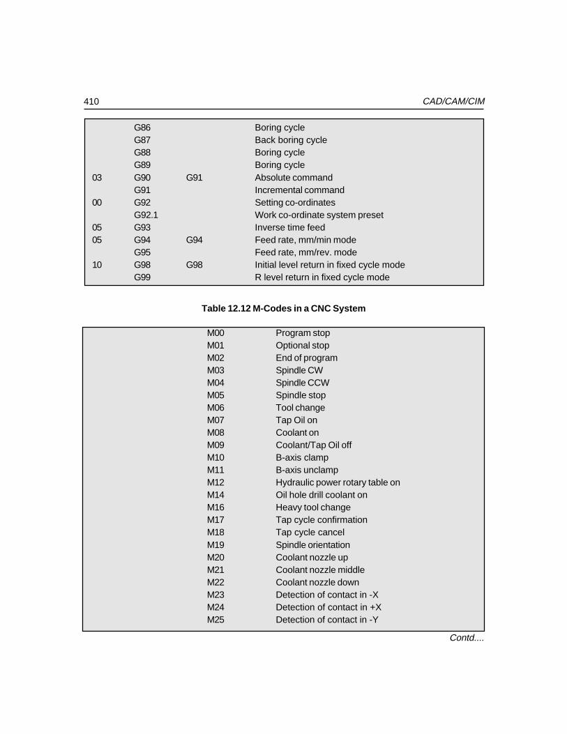
410 CAD/CAM/CIM
G86 Boring cycleG87 Back boring cycleG88 Boring cycleG89 Boring cycle
03 G90 G91 Absolute commandG91 Incremental command
00 G92 Setting co-ordinatesG92.1 Work co-ordinate system preset
05 G93 Inverse time feed05 G94 G94 Feed rate, mm/min mode
G95 Feed rate, mm/rev. mode10 G98 G98 Initial level return in fixed cycle mode
G99 R level return in fixed cycle mode
Table 12.12 M-Codes in a CNC System
M00 Program stopM01 Optional stopM02 End of programM03 Spindle CWM04 Spindle CCWM05 Spindle stopM06 Tool changeM07 Tap Oil onM08 Coolant onM09 Coolant/Tap Oil offM10 B-axis clampM11 B-axis unclampM12 Hydraulic power rotary table onM14 Oil hole drill coolant onM16 Heavy tool changeM17 Tap cycle confirmationM18 Tap cycle cancelM19 Spindle orientationM20 Coolant nozzle upM21 Coolant nozzle middleM22 Coolant nozzle downM23 Detection of contact in -XM24 Detection of contact in +XM25 Detection of contact in -Y
Contd....
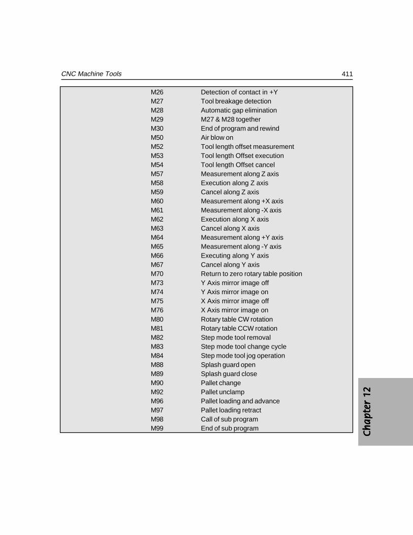
Ch
ap
ter
12C
ha
pte
r 12
Ch
ap
ter
12C
ha
pte
r 12
Ch
ap
ter
12
411CNC Machine Tools
M26 Detection of contact in +YM27 Tool breakage detectionM28 Automatic gap eliminationM29 M27 & M28 togetherM30 End of program and rewindM50 Air blow onM52 Tool length offset measurementM53 Tool length Offset executionM54 Tool length Offset cancelM57 Measurement along Z axisM58 Execution along Z axisM59 Cancel along Z axisM60 Measurement along +X axisM61 Measurement along -X axisM62 Execution along X axisM63 Cancel along X axisM64 Measurement along +Y axisM65 Measurement along -Y axisM66 Executing along Y axisM67 Cancel along Y axisM70 Return to zero rotary table positionM73 Y Axis mirror image offM74 Y Axis mirror image onM75 X Axis mirror image offM76 X Axis mirror image onM80 Rotary table CW rotationM81 Rotary table CCW rotationM82 Step mode tool removalM83 Step mode tool change cycleM84 Step mode tool jog operationM88 Splash guard openM89 Splash guard closeM90 Pallet changeM92 Pallet unclampM96 Pallet loading and advanceM97 Pallet loading retractM98 Call of sub programM99 End of sub program
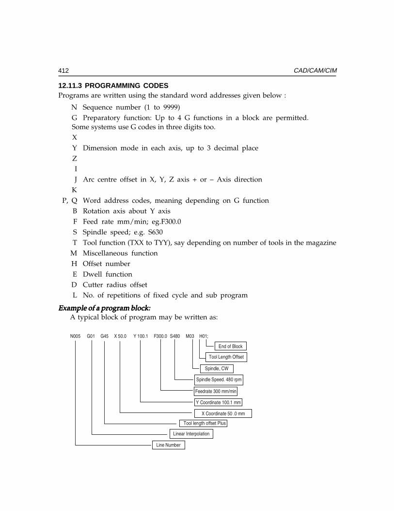
412 CAD/CAM/CIM
12.11.3 PROGRAMMING CODESPrograms are written using the standard word addresses given below :
N Sequence number (1 to 9999)G Preparatory function: Up to 4 G functions in a block are permitted.
Some systems use G codes in three digits too.XY Dimension mode in each axis, up to 3 decimal placeZIJ Arc centre offset in X, Y, Z axis + or – Axis direction
KP, Q Word address codes, meaning depending on G function
B Rotation axis about Y axisF Feed rate mm/min; eg.F300.0S Spindle speed; e.g. S630T Tool function (TXX to TYY), say depending on number of tools in the magazine
M Miscellaneous functionH Offset numberE Dwell functionD Cutter radius offsetL No. of repetitions of fixed cycle and sub program
Example of a program block:Example of a program block:Example of a program block:Example of a program block:Example of a program block:A typical block of program may be written as:
������ ����� ����� ������� ������� ������� ���������������������
��� �� �����
���������� �!��"����
#$����%�&'�
#$����� #��������(#)
����(*�������))+)$�
&��(�$�*�� ���� ))
��&��(�$�*��������))�
���� ����� ���"�� ,�-"
�$��*(�.���(#��*�$���
�$����-)/�(�
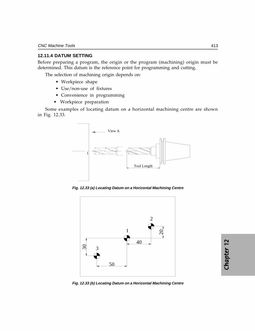
Ch
ap
ter
12C
ha
pte
r 12
Ch
ap
ter
12C
ha
pte
r 12
Ch
ap
ter
12
413CNC Machine Tools
12.11.4 DATUM SETTINGBefore preparing a program, the origin or the program (machining) origin must bedetermined. This datum is the reference point for programming and cutting.
The selection of machining origin depends on:
• Workpiece shape• Use/non-use of fixtures• Convenience in programming
• Workpiece preparation
Some examples of locating datum on a horizontal machining centre are shownin Fig. 12.33.
Tool Length
View A
1
Fig. 12.33 (a) Locating Datum on a Horizontal Machining Centre
40
20
50
30
1
2
3
Fig. 12.33 (b) Locating Datum on a Horizontal Machining Centre
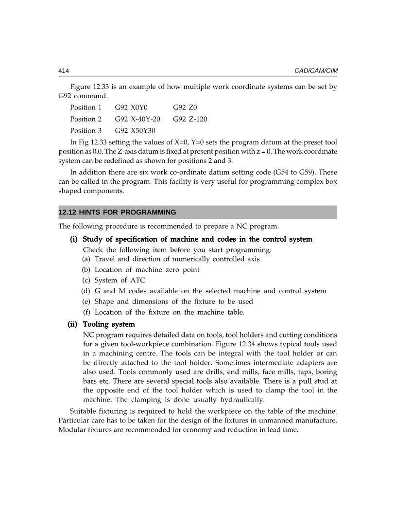
414 CAD/CAM/CIM
Figure 12.33 is an example of how multiple work coordinate systems can be set byG92 command.
Position 1 G92 X0Y0 G92 Z0
Position 2 G92 X-40Y-20 G92 Z-120
Position 3 G92 X50Y30
In Fig 12.33 setting the values of X=0, Y=0 sets the program datum at the preset toolposition as 0.0. The Z-axis datum is fixed at present position with z = 0. The work coordinatesystem can be redefined as shown for positions 2 and 3.
In addition there are six work co-ordinate datum setting code (G54 to G59). Thesecan be called in the program. This facility is very useful for programming complex boxshaped components.
12.12 HINTS FOR PROGRAMMING
The following procedure is recommended to prepare a NC program.
(i)(i)(i)(i)(i) Study of specification of machine and codes in the control systemStudy of specification of machine and codes in the control systemStudy of specification of machine and codes in the control systemStudy of specification of machine and codes in the control systemStudy of specification of machine and codes in the control systemCheck the following item before you start programming:(a) Travel and direction of numerically controlled axis(b) Location of machine zero point(c) System of ATC(d) G and M codes available on the selected machine and control system(e) Shape and dimensions of the fixture to be used(f) Location of the fixture on the machine table.
(ii)(ii)(ii)(ii)(ii) Tooling systemTooling systemTooling systemTooling systemTooling systemNC program requires detailed data on tools, tool holders and cutting conditionsfor a given tool-workpiece combination. Figure 12.34 shows typical tools usedin a machining centre. The tools can be integral with the tool holder or canbe directly attached to the tool holder. Sometimes intermediate adapters arealso used. Tools commonly used are drills, end mills, face mills, taps, boringbars etc. There are several special tools also available. There is a pull stud atthe opposite end of the tool holder which is used to clamp the tool in themachine. The clamping is done usually hydraulically.
Suitable fixturing is required to hold the workpiece on the table of the machine.Particular care has to be taken for the design of the fixtures in unmanned manufacture.Modular fixtures are recommended for economy and reduction in lead time.
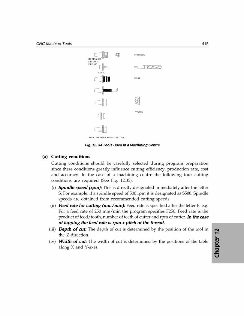
Ch
ap
ter
12C
ha
pte
r 12
Ch
ap
ter
12C
ha
pte
r 12
Ch
ap
ter
12
415CNC Machine Tools
TOOLS
TOOL HOLDERS AND ADAPTORS
BT MAS 403DIN 79871DIN2080
HSK A
Fig. 12. 34 Tools Used in a Machining Centre
(a)(a)(a)(a)(a) Cutting conditionsCutting conditionsCutting conditionsCutting conditionsCutting conditionsCutting conditions should be carefully selected during program preparationsince these conditions greatly influence cutting efficiency, production rate, costand accuracy. In the case of a machining centre the following four cuttingconditions are required (See Fig. 12.35).
(i) Spindle speed (rpm): Spindle speed (rpm): Spindle speed (rpm): Spindle speed (rpm): Spindle speed (rpm): This is directly designated immediately after the letterS. For example, if a spindle speed of 500 rpm it is designated as S500. Spindlespeeds are obtained from recommended cutting speeds.
(ii) Feed rate for cutting (mm/min): Feed rate for cutting (mm/min): Feed rate for cutting (mm/min): Feed rate for cutting (mm/min): Feed rate for cutting (mm/min): Feed rate is specified after the letter F. e.g.For a feed rate of 250 mm/min the program specifies F250. Feed rate is theproduct of feed/tooth, number of teeth of cutter and rpm of cutter. In the caseIn the caseIn the caseIn the caseIn the caseof tapping the feed rate is rpm x pitch of the thread.of tapping the feed rate is rpm x pitch of the thread.of tapping the feed rate is rpm x pitch of the thread.of tapping the feed rate is rpm x pitch of the thread.of tapping the feed rate is rpm x pitch of the thread.
(iii) Depth of cut: Depth of cut: Depth of cut: Depth of cut: Depth of cut: The depth of cut is determined by the position of the tool inthe Z-direction.
(iv) Width of cut: Width of cut: Width of cut: Width of cut: Width of cut: The width of cut is determined by the positions of the tablealong X and Y-axes.
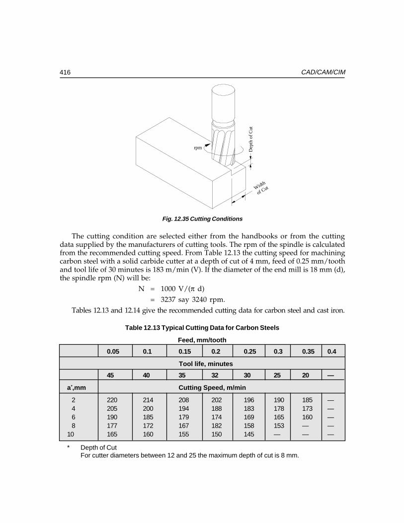
416 CAD/CAM/CIM
Width
of Cut
Dep
th o
f Cut
rpm
Fig. 12.35 Cutting Conditions
The cutting condition are selected either from the handbooks or from the cuttingdata supplied by the manufacturers of cutting tools. The rpm of the spindle is calculatedfrom the recommended cutting speed. From Table 12.13 the cutting speed for machiningcarbon steel with a solid carbide cutter at a depth of cut of 4 mm, feed of 0.25 mm/toothand tool life of 30 minutes is 183 m/min (V). If the diameter of the end mill is 18 mm (d),the spindle rpm (N) will be:
N = 1000 V/(π d)= 3237 say 3240 rpm.
Tables 12.13 and 12.14 give the recommended cutting data for carbon steel and cast iron.
Table 12.13 Typical Cutting Data for Carbon Steels
Feed, mm/tooth
0.05 0.1 0.15 0.2 0.25 0.3 0.35 0.4
Tool life, minutes
45 40 35 32 30 25 20 —
a*,mm Cutting Speed, m/min
2 220 214 208 202 196 190 185 —4 205 200 194 188 183 178 173 —6 190 185 179 174 169 165 160 —8 177 172 167 182 158 153 — —
10 165 160 155 150 145 — — —
* Depth of CutFor cutter diameters between 12 and 25 the maximum depth of cut is 8 mm.
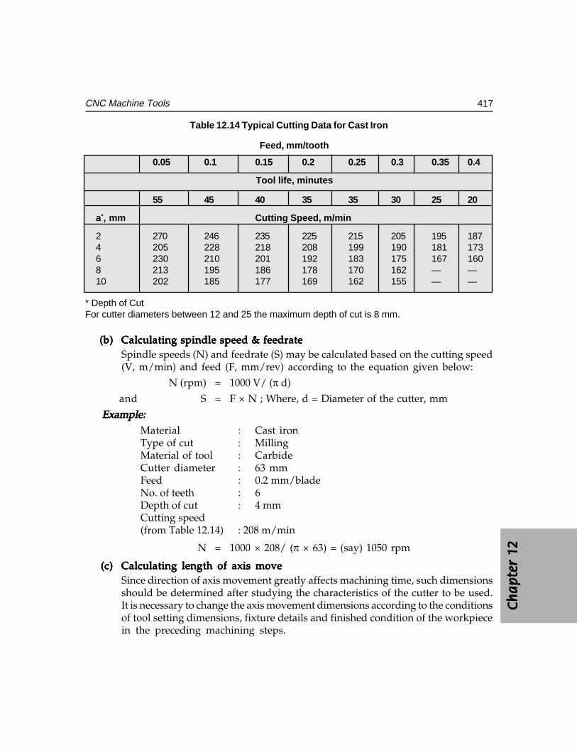
Ch
ap
ter
12C
ha
pte
r 12
Ch
ap
ter
12C
ha
pte
r 12
Ch
ap
ter
12
417CNC Machine Tools
Table 12.14 Typical Cutting Data for Cast Iron
Feed, mm/tooth
0.05 0.1 0.15 0.2 0.25 0.3 0.35 0.4
Tool life, minutes
55 45 40 35 35 30 25 20
a*, mm Cutting Speed, m/min
2 270 246 235 225 215 205 195 1874 205 228 218 208 199 190 181 1736 230 210 201 192 183 175 167 1608 213 195 186 178 170 162 — —10 202 185 177 169 162 155 — —
* Depth of CutFor cutter diameters between 12 and 25 the maximum depth of cut is 8 mm.
(b)(b)(b)(b)(b) Calculating spindle speed & feedrateCalculating spindle speed & feedrateCalculating spindle speed & feedrateCalculating spindle speed & feedrateCalculating spindle speed & feedrateSpindle speeds (N) and feedrate (S) may be calculated based on the cutting speed(V, m/min) and feed (F, mm/rev) according to the equation given below:
N (rpm) = 1000 V/ (π d)
and S = F × N ; Where, d = Diameter of the cutter, mm
Example:Example:Example:Example:Example:Material : Cast ironType of cut : MillingMaterial of tool : CarbideCutter diameter : 63 mmFeed : 0.2 mm/bladeNo. of teeth : 6Depth of cut : 4 mmCutting speed(from Table 12.14) : 208 m/min
N = 1000 × 208/ (π × 63) = (say) 1050 rpm
(c)(c)(c)(c)(c) Calculating length of axis moveCalculating length of axis moveCalculating length of axis moveCalculating length of axis moveCalculating length of axis moveSince direction of axis movement greatly affects machining time, such dimensionsshould be determined after studying the characteristics of the cutter to be used.It is necessary to change the axis movement dimensions according to the conditionsof tool setting dimensions, fixture details and finished condition of the workpiecein the preceding machining steps.
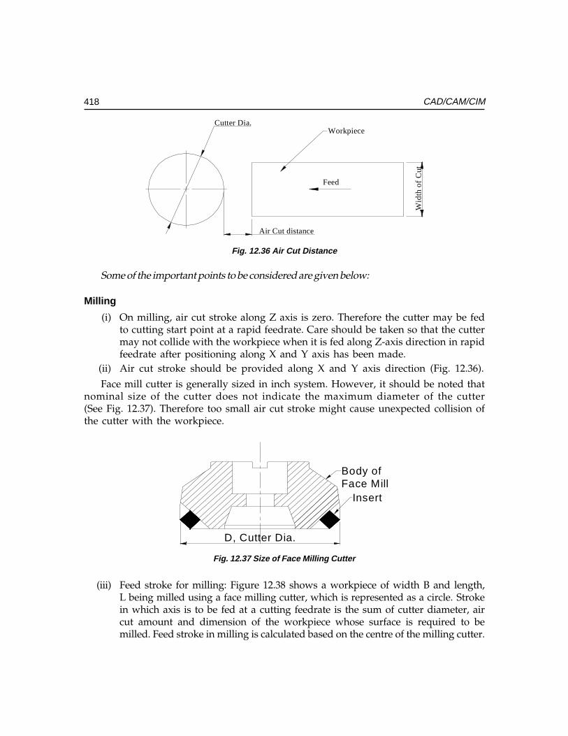
418 CAD/CAM/CIM
Cutter Dia.
Wid
th o
f C
ut
Air Cut distance
Feed
Workpiece
Fig. 12.36 Air Cut Distance
Some of the important points to be considered are given below:
Milling
(i) On milling, air cut stroke along Z axis is zero. Therefore the cutter may be fedto cutting start point at a rapid feedrate. Care should be taken so that the cuttermay not collide with the workpiece when it is fed along Z-axis direction in rapidfeedrate after positioning along X and Y axis has been made.
(ii) Air cut stroke should be provided along X and Y axis direction (Fig. 12.36).
Face mill cutter is generally sized in inch system. However, it should be noted thatnominal size of the cutter does not indicate the maximum diameter of the cutter(See Fig. 12.37). Therefore too small air cut stroke might cause unexpected collision ofthe cutter with the workpiece.
Insert
Body ofFace Mill
D, Cutter Dia.
Fig. 12.37 Size of Face Milling Cutter
(iii) Feed stroke for milling: Figure 12.38 shows a workpiece of width B and length,L being milled using a face milling cutter, which is represented as a circle. Strokein which axis is to be fed at a cutting feedrate is the sum of cutter diameter, aircut amount and dimension of the workpiece whose surface is required to bemilled. Feed stroke in milling is calculated based on the centre of the milling cutter.
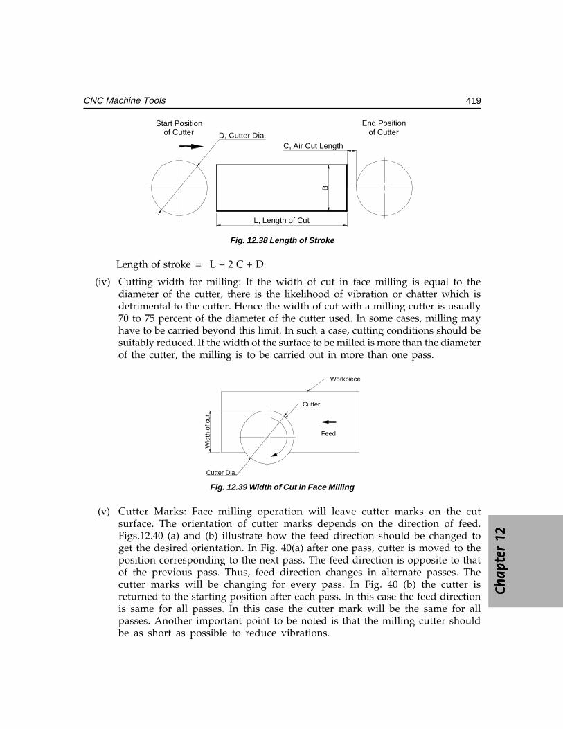
Ch
ap
ter
12C
ha
pte
r 12
Ch
ap
ter
12C
ha
pte
r 12
Ch
ap
ter
12
419CNC Machine Tools
D, Cutter Dia.
Start Positionof Cutter
End Positionof Cutter
C, Air Cut Length
L, Length of Cut
B
Fig. 12.38 Length of Stroke
Length of stroke = L + 2 C + D
(iv) Cutting width for milling: If the width of cut in face milling is equal to thediameter of the cutter, there is the likelihood of vibration or chatter which isdetrimental to the cutter. Hence the width of cut with a milling cutter is usually70 to 75 percent of the diameter of the cutter used. In some cases, milling mayhave to be carried beyond this limit. In such a case, cutting conditions should besuitably reduced. If the width of the surface to be milled is more than the diameterof the cutter, the milling is to be carried out in more than one pass.
Workpiece
Cutter
Wid
th o
f cut
Feed
Cutter Dia.
Fig. 12.39 Width of Cut in Face Milling
(v) Cutter Marks: Face milling operation will leave cutter marks on the cutsurface. The orientation of cutter marks depends on the direction of feed.Figs.12.40 (a) and (b) illustrate how the feed direction should be changed toget the desired orientation. In Fig. 40(a) after one pass, cutter is moved to theposition corresponding to the next pass. The feed direction is opposite to thatof the previous pass. Thus, feed direction changes in alternate passes. Thecutter marks will be changing for every pass. In Fig. 40 (b) the cutter isreturned to the starting position after each pass. In this case the feed directionis same for all passes. In this case the cutter mark will be the same for allpasses. Another important point to be noted is that the milling cutter shouldbe as short as possible to reduce vibrations.
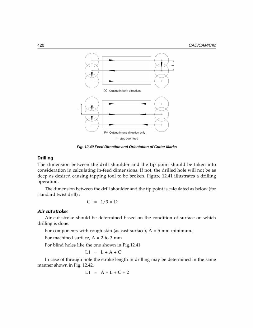
420 CAD/CAM/CIM
(a)
(b)
Cutting in both directions
Cutting in one direction only
f
f
f = step over feed
Fig. 12.40 Feed Direction and Orientation of Cutter Marks
DrillingThe dimension between the drill shoulder and the tip point should be taken intoconsideration in calculating in-feed dimensions. If not, the drilled hole will not be asdeep as desired causing tapping tool to be broken. Figure 12.41 illustrates a drillingoperation.
The dimension between the drill shoulder and the tip point is calculated as below (forstandard twist drill) :
C = 1/3 × D
Air cut stroke:Air cut stroke:Air cut stroke:Air cut stroke:Air cut stroke:Air cut stroke should be determined based on the condition of surface on which
drilling is done.
For components with rough skin (as cast surface), A = 5 mm minimum.
For machined surface, A = 2 to 3 mm
For blind holes like the one shown in Fig.12.41
L1 = L + A + C
In case of through hole the stroke length in drilling may be determined in the samemanner shown in Fig. 12.42.
L1 = A + L + C + 2
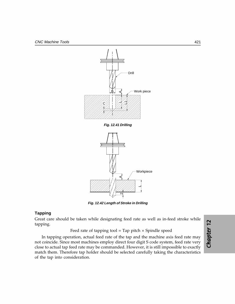
Ch
ap
ter
12C
ha
pte
r 12
Ch
ap
ter
12C
ha
pte
r 12
Ch
ap
ter
12
421CNC Machine Tools
A
C
Drill
Work pieceD
L L1Fig. 12.41 Drilling
A
L
2
Workpiece
Fig. 12.42 Length of Stroke in Drilling
TappingGreat care should be taken while designating feed rate as well as in-feed stroke whiletapping.
Feed rate of tapping tool = Tap pitch × Spindle speed
In tapping operation, actual feed rate of the tap and the machine axis feed rate maynot coincide. Since most machines employ direct four digit S code system, feed rate veryclose to actual tap feed rate may be commanded. However, it is still impossible to exactlymatch them. Therefore tap holder should be selected carefully taking the characteristicsof the tap into consideration.
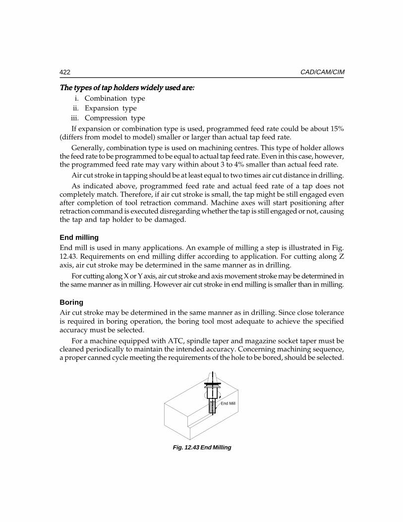
422 CAD/CAM/CIM
The types of tap holders widely used are:The types of tap holders widely used are:The types of tap holders widely used are:The types of tap holders widely used are:The types of tap holders widely used are:i. Combination type
ii. Expansion typeiii. Compression typeIf expansion or combination type is used, programmed feed rate could be about 15%
(differs from model to model) smaller or larger than actual tap feed rate.Generally, combination type is used on machining centres. This type of holder allows
the feed rate to be programmed to be equal to actual tap feed rate. Even in this case, however,the programmed feed rate may vary within about 3 to 4% smaller than actual feed rate.
Air cut stroke in tapping should be at least equal to two times air cut distance in drilling.As indicated above, programmed feed rate and actual feed rate of a tap does not
completely match. Therefore, if air cut stroke is small, the tap might be still engaged evenafter completion of tool retraction command. Machine axes will start positioning afterretraction command is executed disregarding whether the tap is still engaged or not, causingthe tap and tap holder to be damaged.
End millingEnd mill is used in many applications. An example of milling a step is illustrated in Fig.12.43. Requirements on end milling differ according to application. For cutting along Zaxis, air cut stroke may be determined in the same manner as in drilling.
For cutting along X or Y axis, air cut stroke and axis movement stroke may be determined inthe same manner as in milling. However air cut stroke in end milling is smaller than in milling.
BoringAir cut stroke may be determined in the same manner as in drilling. Since close toleranceis required in boring operation, the boring tool most adequate to achieve the specifiedaccuracy must be selected.
For a machine equipped with ATC, spindle taper and magazine socket taper must becleaned periodically to maintain the intended accuracy. Concerning machining sequence,a proper canned cycle meeting the requirements of the hole to be bored, should be selected.
End Mill
Fig. 12.43 End Milling
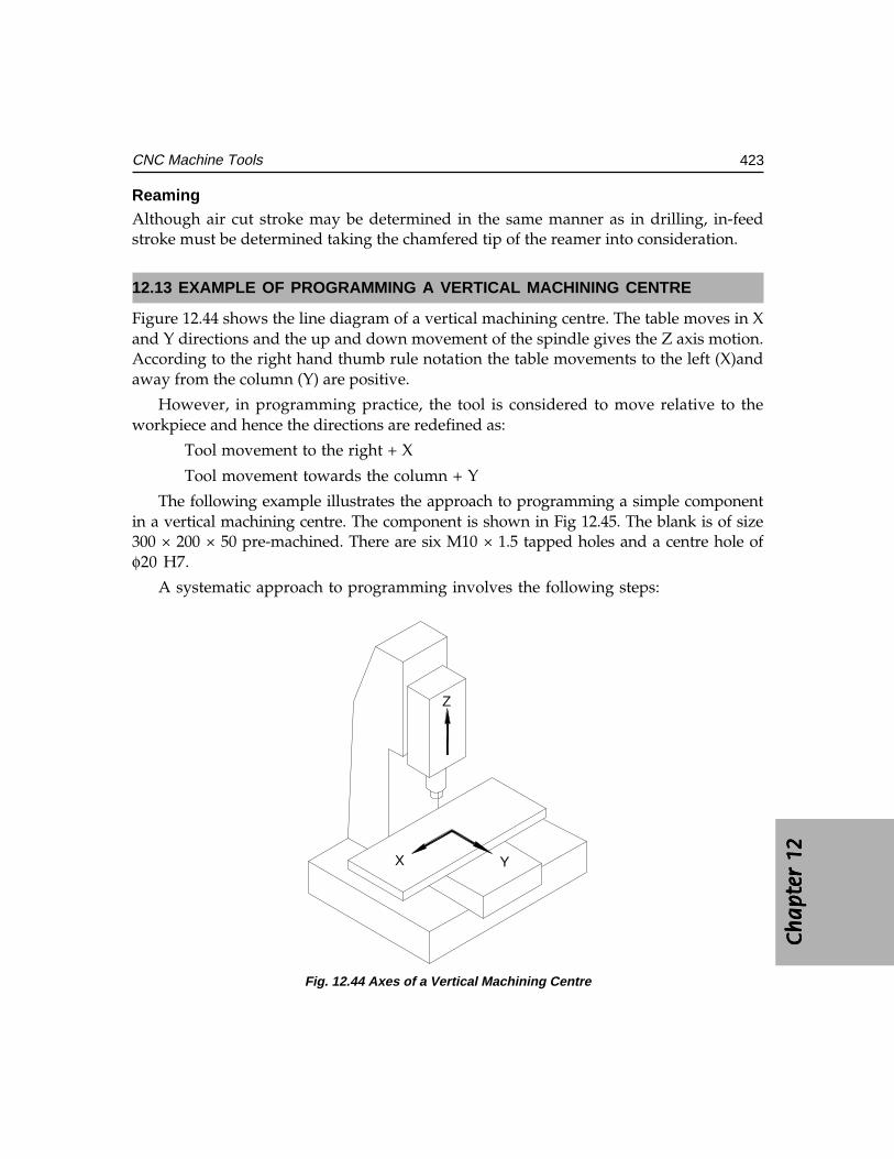
Ch
ap
ter
12C
ha
pte
r 12
Ch
ap
ter
12C
ha
pte
r 12
Ch
ap
ter
12
423CNC Machine Tools
ReamingAlthough air cut stroke may be determined in the same manner as in drilling, in-feedstroke must be determined taking the chamfered tip of the reamer into consideration.
12.13 EXAMPLE OF PROGRAMMING A VERTICAL MACHINING CENTRE
Figure 12.44 shows the line diagram of a vertical machining centre. The table moves in Xand Y directions and the up and down movement of the spindle gives the Z axis motion.According to the right hand thumb rule notation the table movements to the left (X)andaway from the column (Y) are positive.
However, in programming practice, the tool is considered to move relative to theworkpiece and hence the directions are redefined as:
Tool movement to the right + X
Tool movement towards the column + Y
The following example illustrates the approach to programming a simple componentin a vertical machining centre. The component is shown in Fig 12.45. The blank is of size300 × 200 × 50 pre-machined. There are six M10 × 1.5 tapped holes and a centre hole ofφ20 H7.
A systematic approach to programming involves the following steps:
Z
X Y
Fig. 12.44 Axes of a Vertical Machining Centre
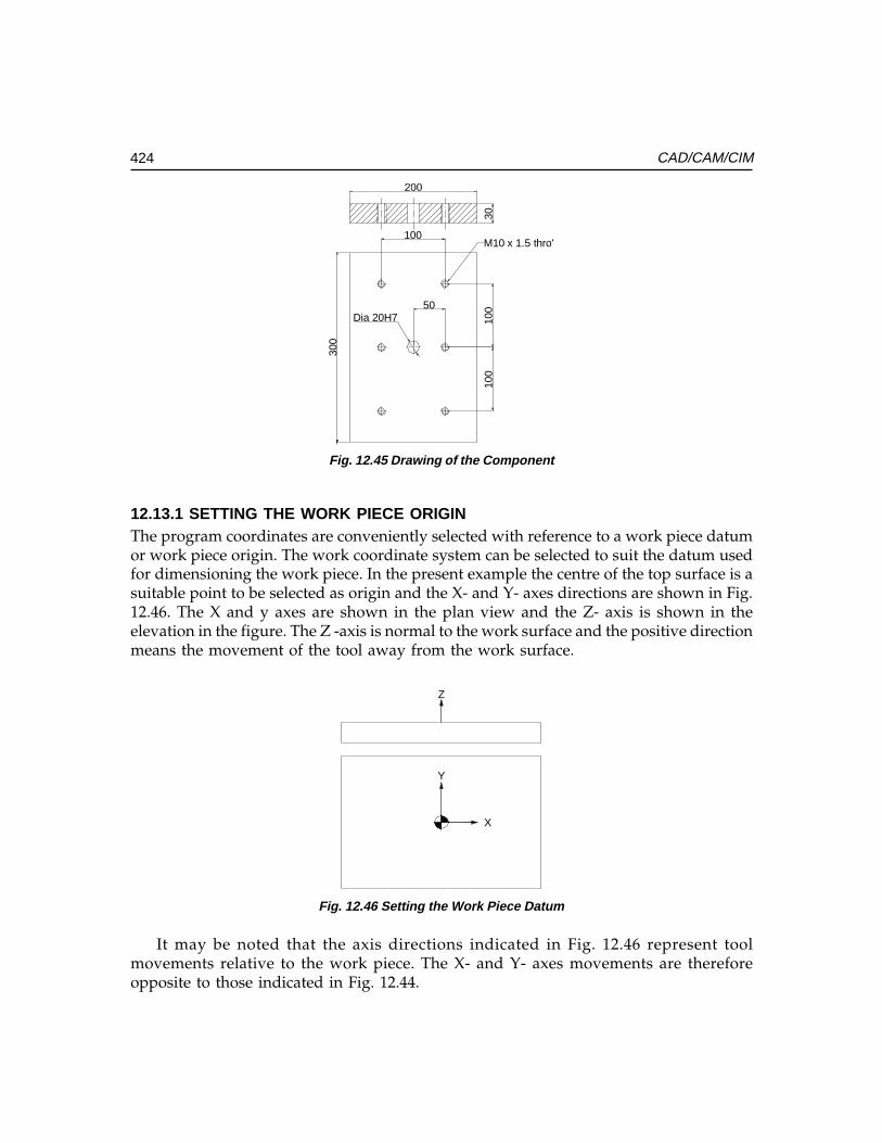
424 CAD/CAM/CIM
100
100
100
50Dia 20H7
30
M10 x 1.5 thro'
300
Fig. 12.45 Drawing of the Component
12.13.1 SETTING THE WORK PIECE ORIGINThe program coordinates are conveniently selected with reference to a work piece datumor work piece origin. The work coordinate system can be selected to suit the datum usedfor dimensioning the work piece. In the present example the centre of the top surface is asuitable point to be selected as origin and the X- and Y- axes directions are shown in Fig.12.46. The X and y axes are shown in the plan view and the Z- axis is shown in theelevation in the figure. The Z -axis is normal to the work surface and the positive directionmeans the movement of the tool away from the work surface.
X
Y
Z
Fig. 12.46 Setting the Work Piece Datum
It may be noted that the axis directions indicated in Fig. 12.46 represent toolmovements relative to the work piece. The X- and Y- axes movements are thereforeopposite to those indicated in Fig. 12.44.
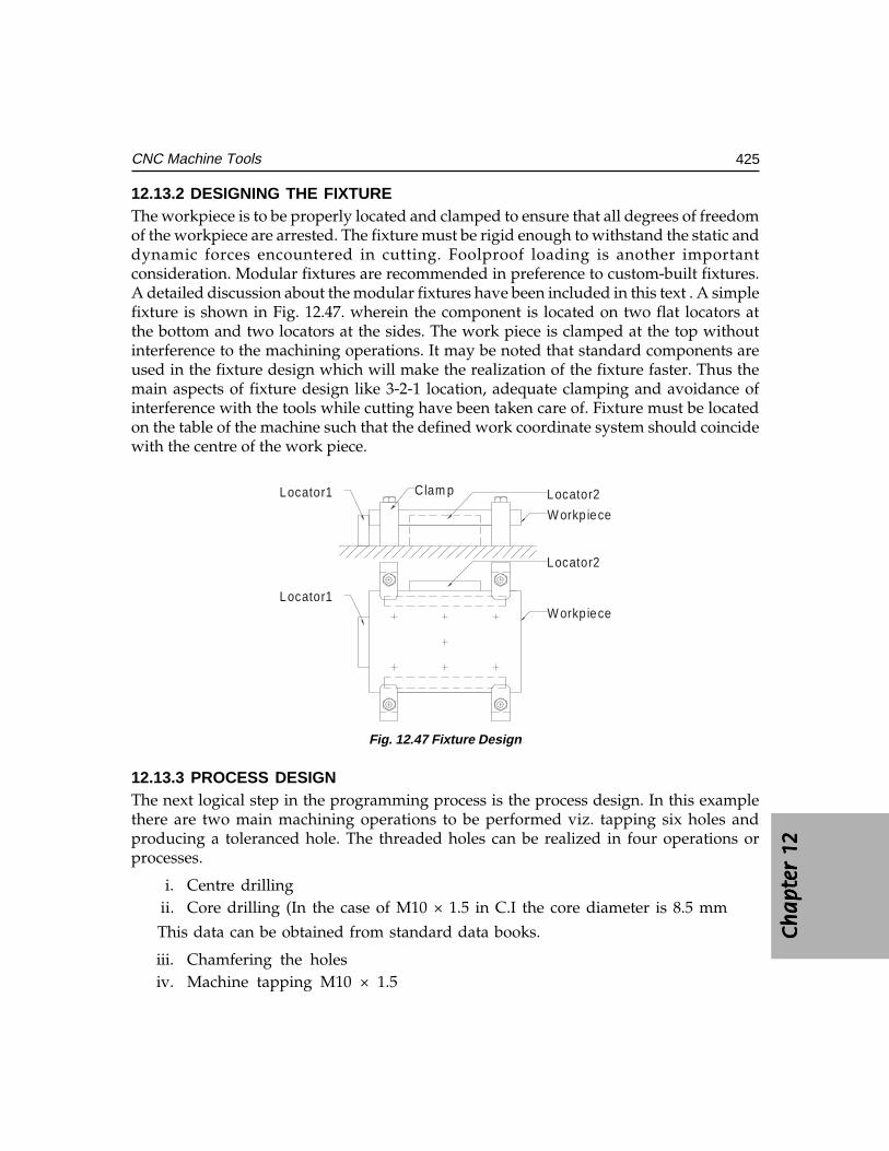
Ch
ap
ter
12C
ha
pte
r 12
Ch
ap
ter
12C
ha
pte
r 12
Ch
ap
ter
12
425CNC Machine Tools
12.13.2 DESIGNING THE FIXTUREThe workpiece is to be properly located and clamped to ensure that all degrees of freedomof the workpiece are arrested. The fixture must be rigid enough to withstand the static anddynamic forces encountered in cutting. Foolproof loading is another importantconsideration. Modular fixtures are recommended in preference to custom-built fixtures.A detailed discussion about the modular fixtures have been included in this text . A simplefixture is shown in Fig. 12.47. wherein the component is located on two flat locators atthe bottom and two locators at the sides. The work piece is clamped at the top withoutinterference to the machining operations. It may be noted that standard components areused in the fixture design which will make the realization of the fixture faster. Thus themain aspects of fixture design like 3-2-1 location, adequate clamping and avoidance ofinterference with the tools while cutting have been taken care of. Fixture must be locatedon the table of the machine such that the defined work coordinate system should coincidewith the centre of the work piece.
Locator1
Locator1
Locator2
Locator2
W orkp iece
W orkp iece
Clam p
Fig. 12.47 Fixture Design
12.13.3 PROCESS DESIGNThe next logical step in the programming process is the process design. In this examplethere are two main machining operations to be performed viz. tapping six holes andproducing a toleranced hole. The threaded holes can be realized in four operations orprocesses.
i. Centre drillingii. Core drilling (In the case of M10 × 1.5 in C.I the core diameter is 8.5 mm
This data can be obtained from standard data books.
iii. Chamfering the holesiv. Machine tapping M10 × 1.5
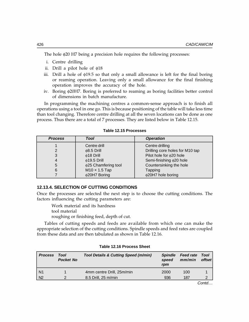
426 CAD/CAM/CIM
Contd....
The hole φ20 H7 being a precision hole requires the following processes:
i. Centre drillingii. Drill a pilot hole of φ18
iii. Drill a hole of φ19.5 so that only a small allowance is left for the final boringor reaming operation. Leaving only a small allowance for the final finishingoperation improves the accuracy of the hole.
iv. Boring φ20H7. Boring is preferred to reaming as boring facilities better controlof dimensions in batch manufacture.
In programming the machining centres a common-sense approach is to finish alloperations using a tool in one go. This is because positioning of the table will take less timethan tool changing. Therefore centre drilling at all the seven locations can be done as oneprocess. Thus there are a total of 7 processes. They are listed below in Table 12.15.
Table 12.15 Processes
Process Tool Operation
1 Centre drill Centre drilling2 φ8.5 Drill Drilling core holes for M10 tap3 φ18 Drill Pilot hole for φ20 hole4 φ19.5 Drill Semi-finishing φ20 hole5 φ25 Chamfering tool Countersinking the hole6 M10 × 1.5 Tap Tapping7 φ20H7 Boring φ20H7 hole boring
12.13.4. SELECTION OF CUTTING CONDITIONSOnce the processes are selected the next step is to choose the cutting conditions. Thefactors influencing the cutting parameters are:
Work material and its hardnesstool materialroughing or finishing feed, depth of cut.
Tables of cutting speeds and feeds are available from which one can make theappropriate selection of the cutting conditions. Spindle speeds and feed rates are coupledfrom these data and are then tabulated as shown in Table 12.16.
Table 12.16 Process Sheet
Process Tool Tool Details & Cutting Speed (m/min) Spindle Feed rate ToolPocket No speed mm/min offset
rpm
N1 1 4mm centre Drill, 25m/min 2000 100 1N2 2 8.5 Drill, 25 m/min 936 187 2
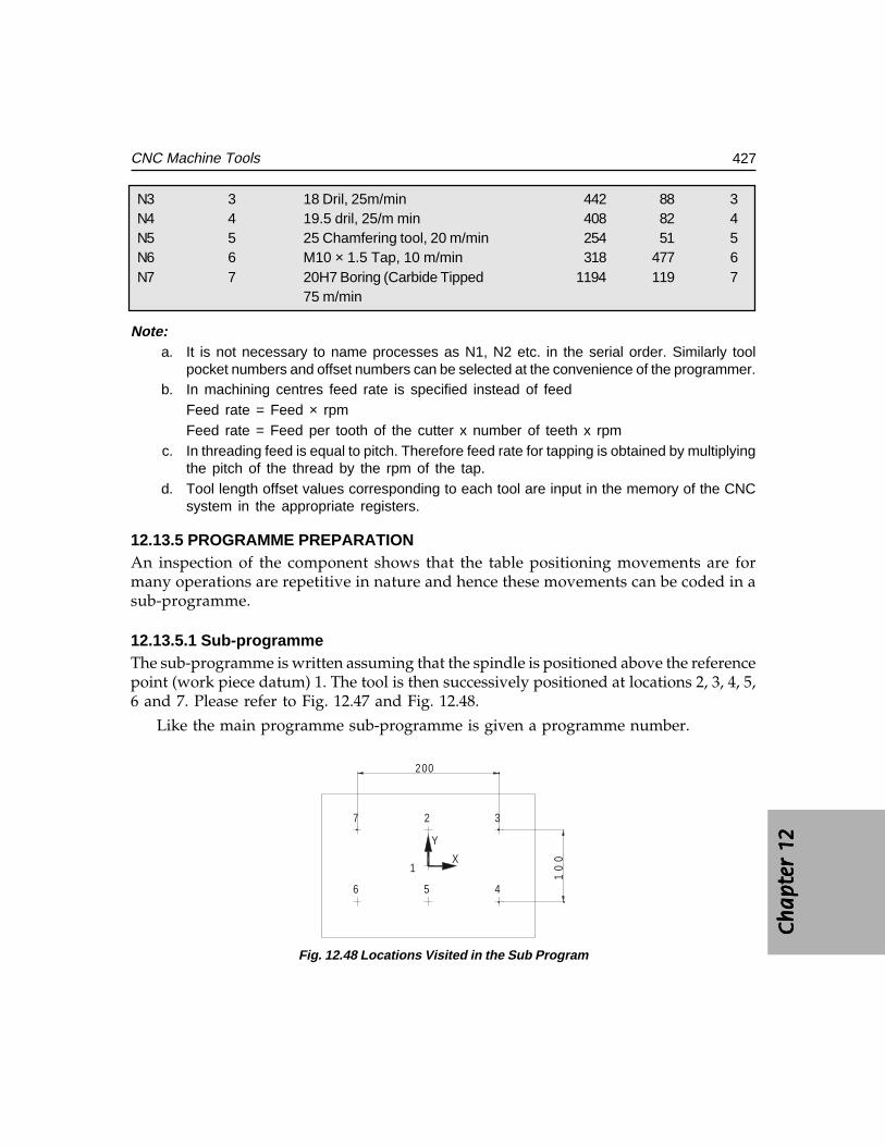
Ch
ap
ter
12C
ha
pte
r 12
Ch
ap
ter
12C
ha
pte
r 12
Ch
ap
ter
12
427CNC Machine Tools
N3 3 18 Dril, 25m/min 442 88 3N4 4 19.5 dril, 25/m min 408 82 4N5 5 25 Chamfering tool, 20 m/min 254 51 5N6 6 M10 × 1.5 Tap, 10 m/min 318 477 6N7 7 20H7 Boring (Carbide Tipped 1194 119 7
75 m/min
Note:a. It is not necessary to name processes as N1, N2 etc. in the serial order. Similarly tool
pocket numbers and offset numbers can be selected at the convenience of the programmer.b. In machining centres feed rate is specified instead of feed
Feed rate = Feed × rpmFeed rate = Feed per tooth of the cutter x number of teeth x rpm
c. In threading feed is equal to pitch. Therefore feed rate for tapping is obtained by multiplyingthe pitch of the thread by the rpm of the tap.
d. Tool length offset values corresponding to each tool are input in the memory of the CNCsystem in the appropriate registers.
12.13.5 PROGRAMME PREPARATIONAn inspection of the component shows that the table positioning movements are formany operations are repetitive in nature and hence these movements can be coded in asub-programme.
12.13.5.1 Sub-programmeThe sub-programme is written assuming that the spindle is positioned above the referencepoint (work piece datum) 1. The tool is then successively positioned at locations 2, 3, 4, 5,6 and 7. Please refer to Fig. 12.47 and Fig. 12.48.
Like the main programme sub-programme is given a programme number.
1
2 3
456
7
200
10
0X
Y
Fig. 12.48 Locations Visited in the Sub Program

428 CAD/CAM/CIM
027 ;(Programme Number 27. This number is used to call the sub-programme in themain programme.)
X0.0 Y50.0 ; (Position 2)X100.0 ; (Position 2)Y-50.0 ;X0.0;X-100.0 ;Y50.0 ;M 99 ; (Return to the main programme)
12.13.5.2 Main Programme018 ; (Programme number 18)(Part-name)
G0 G40 G80 ; (Rapid traverse)(Cutter compensation cancel)(Canned cycle cancel)
G91 G28 X0 Y0 Z0 ; (Incremental positioning)(XYZ zero return)
/T1 ; (Call tool in Pocket #1 Centre Drill)
/M06 (Call tool change)(Tool #1 is now inserted in the spindle)
Note :Note :Note :Note :Note : Block delete switch (/////) is used here as these blocks are used only during set up. Theseblocks with “/” sign are again provided at the end of the programme. Hence during repeated machiningthe block delete switch is kept in the ononononon position and these lines preceding / symbol are ignored.
M1 ; ( An optional stop code is introduced so that the program will
Temporarily cease execution to facilitate inspection. The
program will continue if the “ Start” button is pressed. Once theprogram is proven, the optional stop switch is shifted to “off”mode so that M1 code is ignored.)
(Centre Drilling)(Centre Drilling)(Centre Drilling)(Centre Drilling)(Centre Drilling)N1 T2 ; (Calling next tool i.e. 8.5 Drill)
G0 G90 G54 G43 X0 Y0 Z50.0 H1 S2000 M3 ;(Select work co-ordinate system (G54)Rapid positioning above location 1Tool length offset 1 activeSpindle speed 2000 rpmSpindle rotation clockwise (M03))
Ch
ap
ter
12C
ha
pte
r 12
Ch
ap
ter
12C
ha
pte
r 12
Ch
ap
ter
12
429CNC Machine Tools
G98 G81 Z-8.0 R47.0 F100.0 (Canned cycle (Drilling) G81Return to Initial position (G98)Drilling depth = –5 mmRapid up to Z = 3 mmFeed rate 100 mm / min)
M98 P27 ; (Calling sub programme #27- Centre drilling in 7 locations)
G80 G91 G28 Z0 ; (Fixed cycle cancelZ axis zero return)
M6 ; (8.5 mm drill is now inserted in the spindleThe centre drill is returned to the tool magazine)
M1 ; Optional stop
5
5
Initial Level
Rapid Level
WorkPiece
Fig. 12.49 Centre Drilling Cycle
(8.5 Drill)N2 T2 (Process #2, calling Tool #3)G0 G90 G43 X0 Y0 Z50.0 H2 S936 M3;G99 G81 Z-38.0 R47.0 F187 L0; (Rapid traverse to stop at Z=3 mm
Depth = 35 mmReturn to initial rapid level (G99)No machining to be done at thisposition (L0))
M98 P27 ;G80 G91 G28 Z0 ; Returned to Z home position for
tool change
M 6 ;

430 CAD/CAM/CIM
M1 ;
(18 DIA DRILL)N3 T4 ;G0 G90 G43 X0 Y0 Z50.0 H3 S442 M3 ;G81 Z41.0 R47.0 F88 ;M 98 P27 ;M6 ;M1 ;
(19.5 DRILL)N4 T5;G0 G90 G43 X0 Y0 Z50.0 H4 S408 M3 ;G81 Z -38.0 R47.0 F82 ;G80 G91 G28 Z0 ;M6 ;M1 ;
(CHAMFERING)N5 T6 ;G0 G90 G43 X0 Y0 Z50.0 H3 S442 M3 ;G81 Z-41.0 R47.0 F88 ;G80G91G28Z0;S500 H5 M3;G99G81 Z - 6.0 R47.0 F51 L0 ;M98 P27G80 G91 G28 Z0 ;M6 ;M1 ;
(M10 × 1.5 TAP)G0 G90 G43 X0 Y0 Z50.0 H6 S318 M3 ;G84 Z-38.0 R40.0 F477 L0;
(Note:Note:Note:Note:Note: Tapping cycle G84 involves rapid traverse, feed, reverse feed and return)
M98 P27 ;G80 G91 G28 Z0;M6 ;M1 ;(f20 H7 BORING)N7 T1 ;G0 G90 G43 X0 Y0 Z50.0 H7 S1194 M3;
(Note:Note:Note:Note:Note: Boring, being a critical operation is performed in two stages during initial trials. Adistance of 5 mm is first machined and the operator can check whether the hole is within tolerance

Ch
ap
ter
12C
ha
pte
r 12
Ch
ap
ter
12C
ha
pte
r 12
Ch
ap
ter
12
431CNC Machine Tools
limits. That is why the four succeeding lines of programme starts with block delete symbol.Once the setting of the boring bar is proven to be satisfactory the block delete switch can bethrown into the “ON’ position thereby ignoring these lines during regular production run)
/G81 Z-5.0 R3.0 F119 ;/G80 G91 G28 Z0 M5 ;/M1 ;/G0 G90 G43 X0 Y0 Z50.0 H7 M3 ;/G81 Z-8.0 R47.0 F119 ;/G80 G91 G28 Z0 M5 ;/M1 ;/G0 G90 G43 X0 Y0 Z50.0 H7 M3 ;G76 Z-35.0 R47.0 P0.5 Q0.5 F119 ; (P, Dwell 0.5 Sec,
Q, Offset 0.5 mm)Note:Note:Note:Note:Note: G76 is precision boring operation. At the end of the boring operation the tool is
withdrawn along the radial direction at the orientated stop position of the spindle. There is adwell of 0.5 sec and the boring bar is withdrawn.
G80 G91 G28 Z0 ;M6 ;M30 ;
Note: Note: Note: Note: Note: The readers are advised to compare the G and M codes used in this program with theG and M codes of the machines available with them as there may be differences in the G-Codesand m codes from system to system.
12.14 CNC TURNING A GEAR BLANK
Figure 12.50 shows the cross section of a part to be machined in a CNC lathe. Providingfor facing and turning allowances the blank (Fig. 12.51) have a diameter of 71 mm andlength 24 mm.
R2
10.2
22.2
2 x 45
1 x 45
Dia
52
Dia
24
.75
Dia
. 6
6.9
h1
1
10
Material: 40Ni2 Cr1Mo28
N7
Fig. 12.50 Drawing of the Component
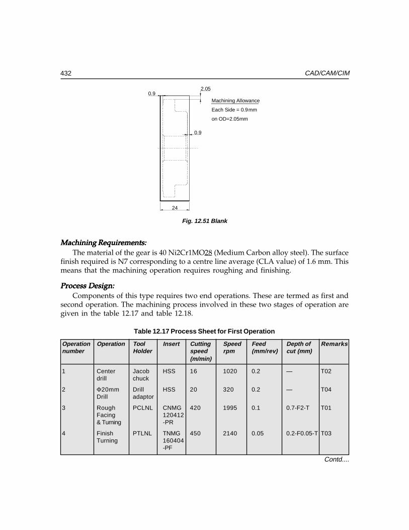
432 CAD/CAM/CIM
0.9
0.92.05
24
Machining Allowance
on OD=2.05mm
Each Side = 0.9mm
Fig. 12.51 Blank
Machining Requirements:Machining Requirements:Machining Requirements:Machining Requirements:Machining Requirements:The material of the gear is 40 Ni2Cr1MO28 (Medium Carbon alloy steel). The surface
finish required is N7 corresponding to a centre line average (CLA value) of 1.6 mm. Thismeans that the machining operation requires roughing and finishing.
Process Design:Process Design:Process Design:Process Design:Process Design:Components of this type requires two end operations. These are termed as first and
second operation. The machining process involved in these two stages of operation aregiven in the table 12.17 and table 12.18.
Table 12.17 Process Sheet for First Operation
Operation Operation Tool Insert Cutting Speed Feed Depth of Remarksnumber Holder speed rpm (mm/rev) cut (mm)
(m/min)
1 Center Jacob HSS 16 1020 0.2 — T02drill chuck
2 Φ20mm Drill HSS 20 320 0.2 — T04Drill adaptor
3 Rough PCLNL CNMG 420 1995 0.1 0.7-F2-T T01Facing 120412& Turning -PR
4 Finish PTLNL TNMG 450 2140 0.05 0.2-F0.05-T T03Turning 160404
-PF
Contd....
Ch
ap
ter
12C
ha
pte
r 12
Ch
ap
ter
12C
ha
pte
r 12
Ch
ap
ter
12
433CNC Machine Tools
5 24.25 mm PTFNL TNMG 80 1050 0.1 2.125 T06Rough 160404boring
6 24.75mm PTFNL TNMG 100 1285 0.05 0.25 T06finish 160404boring
Work Material: 40Ni2Cr1M028 Hardness :229-277 BHN
Table 12.18 Process Sheet for Second Operation
Operation Operation Tool Insert Cutting Speed Feed Depth of Remarksnumber Holder speed rpm (mm/rev) cut (mm)
(m/min)
1 Rough PCLNL CNMG 420 0.1 0.7 – F T01 Facing & 120412 2 - TTurning -PR
2 Finish PTTNL TNMG 450 0.05 0.2 – F T03Turning 160404 0.05 – T
-PF
3 Boring PTFNL TNMG 80 1285 0.1 1.375 T06160404
Tool Length Offset:Tool Length Offset:Tool Length Offset:Tool Length Offset:Tool Length Offset:The tool length offset is the distance between the home position and the work piece
datum. The work piece datum is the point at which the X and Z co-ordinates on thecomponent is zero. Normally, for cylindrical parts the datum is fixed along the axis onthe finished surface of the workpiece.
Procedure for setting the work piece datum:
i. First the tool turret is moved to the machine datum (home position). Here thevalues of X and Z will be zero.
ii. The tool is then moved in JOG mode / MPG mode and it is touched on the faceof the component. The Z value shown will be the tool length offset. This valueis entered in the offset page or allowance for facing shall be added with this valueif needed.
iii. The tool is then touched along the periphery of the component. The X value notedat this position is added with the radius of the component to set the X datumalong the axis. This value is entered in the tool offset page.
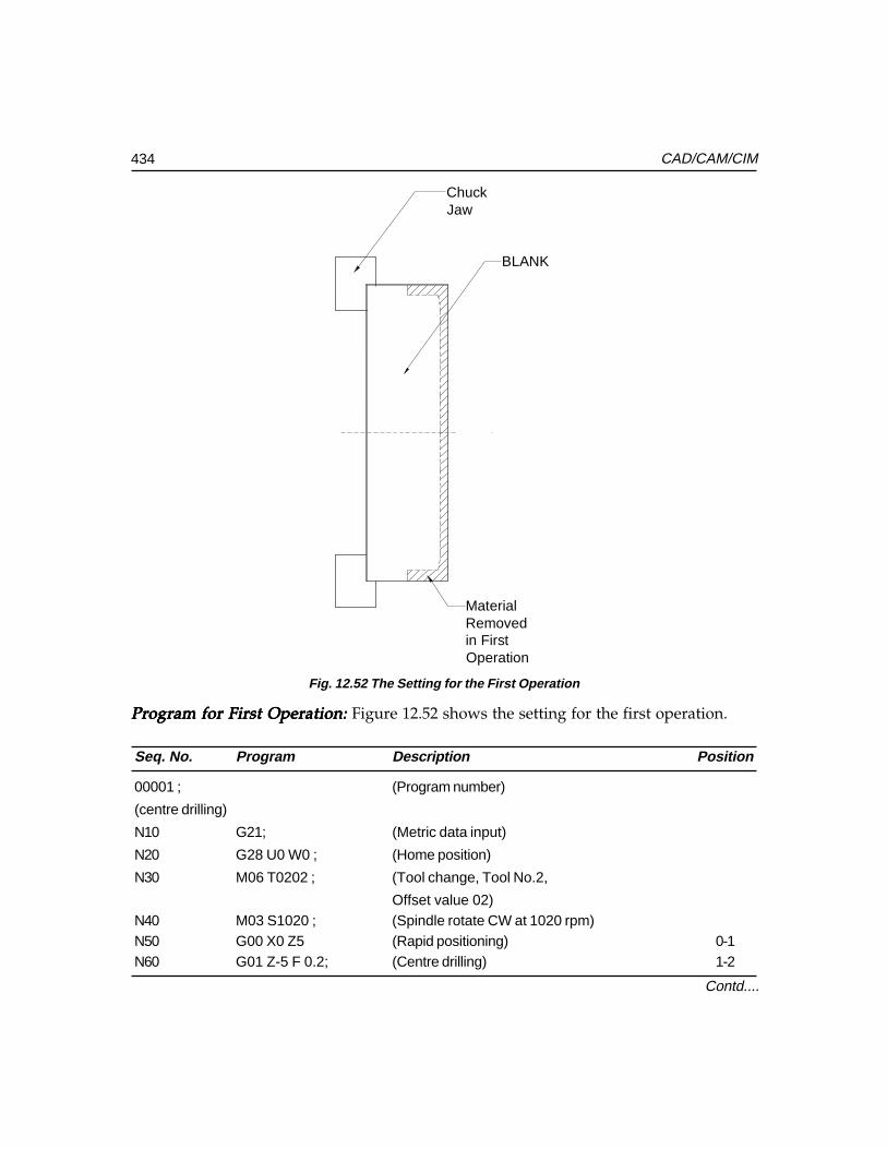
434 CAD/CAM/CIM
BLANK
MaterialRemovedin FirstOperation
ChuckJaw
Seq. No. Program Description Position
00001 ; (Program number)
(centre drilling)
N10 G21; (Metric data input)
N20 G28 U0 W0 ; (Home position)
N30 M06 T0202 ; (Tool change, Tool No.2,
Offset value 02)N40 M03 S1020 ; (Spindle rotate CW at 1020 rpm)N50 G00 X0 Z5 (Rapid positioning) 0-1N60 G01 Z-5 F 0.2; (Centre drilling) 1-2
Program for First Operation: Program for First Operation: Program for First Operation: Program for First Operation: Program for First Operation: Figure 12.52 shows the setting for the first operation.
Fig. 12.52 The Setting for the First Operation
Contd....
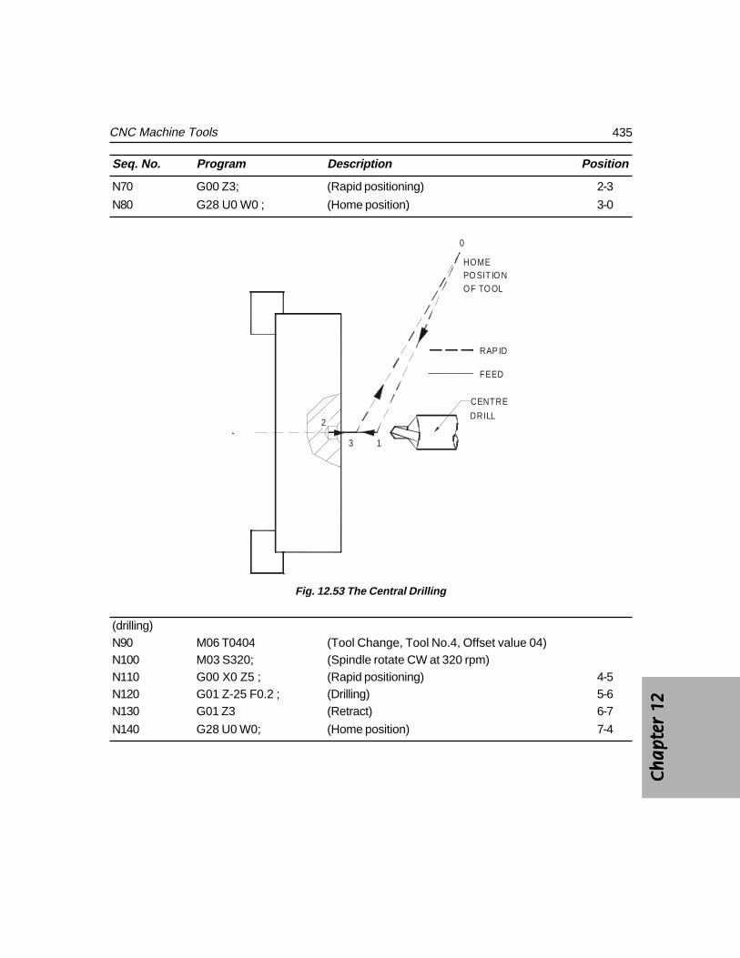
Ch
ap
ter
12C
ha
pte
r 12
Ch
ap
ter
12C
ha
pte
r 12
Ch
ap
ter
12
435CNC Machine Tools
Seq. No. Program Description Position
N70 G00 Z3; (Rapid positioning) 2-3
N80 G28 U0 W0 ; (Home position) 3-0
0
1
2
3
CENTRE
DRILL
HOMEPO SIT IO NOF TO OL
RAP ID
FEED
Fig. 12.53 The Central Drilling
(drilling)N90 M06 T0404 (Tool Change, Tool No.4, Offset value 04)N100 M03 S320; (Spindle rotate CW at 320 rpm)N110 G00 X0 Z5 ; (Rapid positioning) 4-5N120 G01 Z-25 F0.2 ; (Drilling) 5-6N130 G01 Z3 (Retract) 6-7
N140 G28 U0 W0; (Home position) 7-4
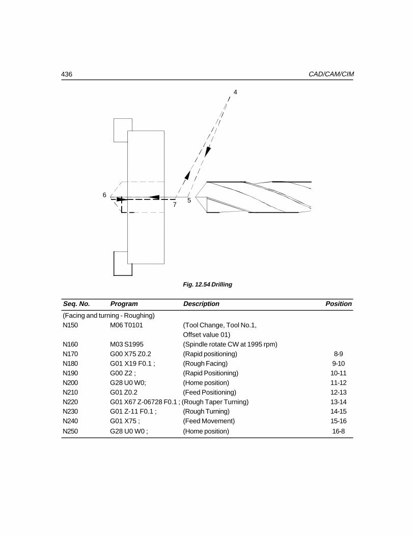
436 CAD/CAM/CIM
4
56
7
Fig. 12.54 Drilling
Seq. No. Program Description Position
(Facing and turning - Roughing)N150 M06 T0101 (Tool Change, Tool No.1,
Offset value 01)N160 M03 S1995 (Spindle rotate CW at 1995 rpm)N170 G00 X75 Z0.2 (Rapid positioning) 8-9N180 G01 X19 F0.1 ; (Rough Facing) 9-10N190 G00 Z2 ; (Rapid Positioning) 10-11N200 G28 U0 W0; (Home position) 11-12N210 G01 Z0.2 (Feed Positioning) 12-13N220 G01 X67 Z-06728 F0.1 ; (Rough Taper Turning) 13-14N230 G01 Z-11 F0.1 ; (Rough Turning) 14-15N240 G01 X75 ; (Feed Movement) 15-16
N250 G28 U0 W0 ; (Home position) 16-8
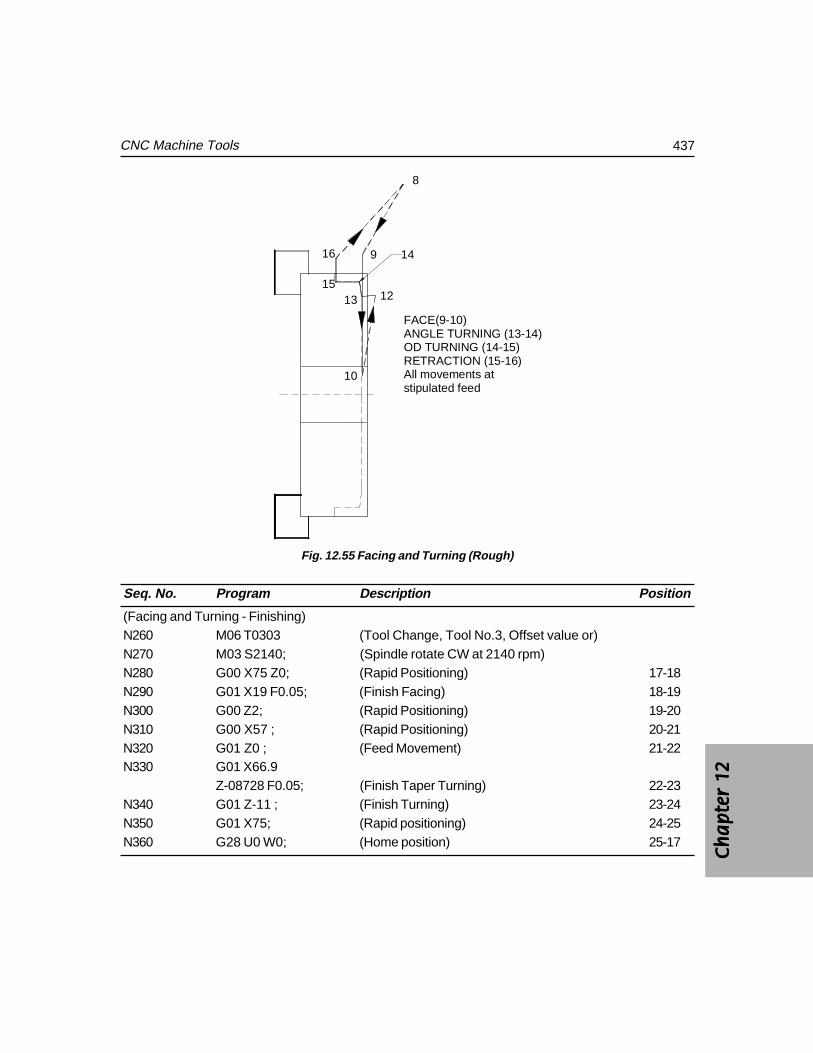
Ch
ap
ter
12C
ha
pte
r 12
Ch
ap
ter
12C
ha
pte
r 12
Ch
ap
ter
12
437CNC Machine Tools
8
9
10
121315
16 14
FACE(9-10)ANGLE TURNING (13-14)OD TURNING (14-15)RETRACTION (15-16)All movements atstipulated feed
Fig. 12.55 Facing and Turning (Rough)
Seq. No. Program Description Position
(Facing and Turning - Finishing)N260 M06 T0303 (Tool Change, Tool No.3, Offset value or)N270 M03 S2140; (Spindle rotate CW at 2140 rpm)N280 G00 X75 Z0; (Rapid Positioning) 17-18N290 G01 X19 F0.05; (Finish Facing) 18-19N300 G00 Z2; (Rapid Positioning) 19-20N310 G00 X57 ; (Rapid Positioning) 20-21N320 G01 Z0 ; (Feed Movement) 21-22N330 G01 X66.9
Z-08728 F0.05; (Finish Taper Turning) 22-23N340 G01 Z-11 ; (Finish Turning) 23-24N350 G01 X75; (Rapid positioning) 24-25N360 G28 U0 W0; (Home position) 25-17
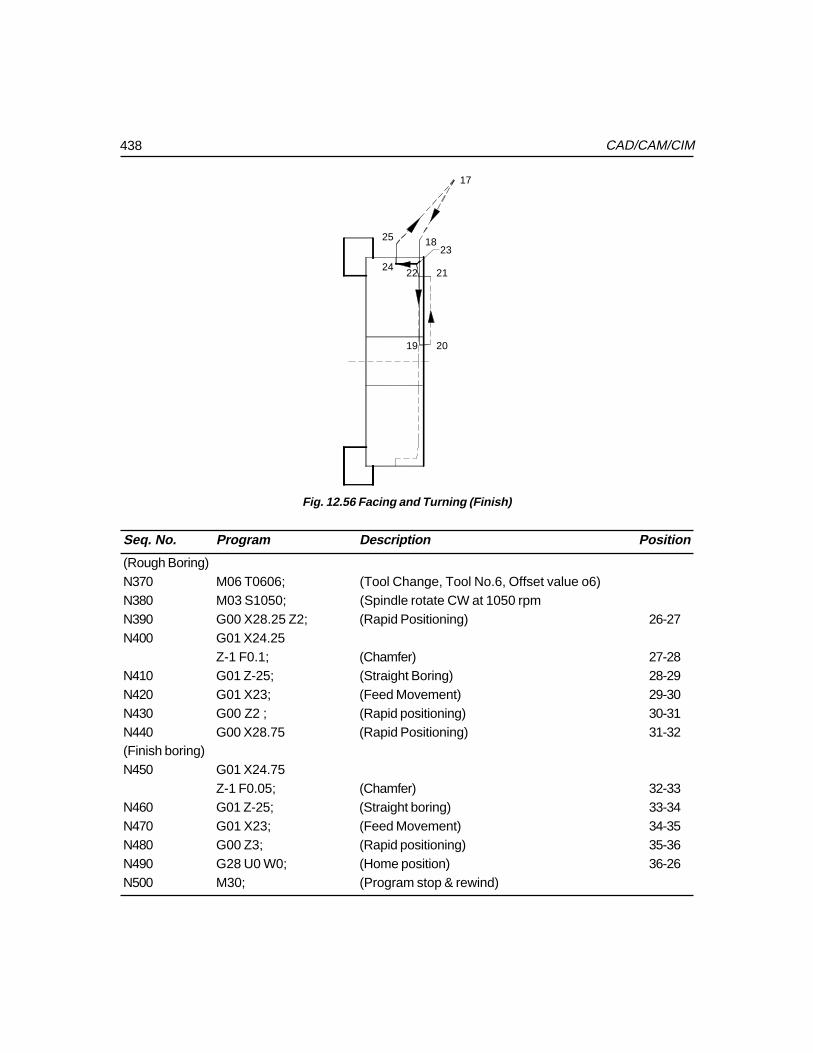
438 CAD/CAM/CIM
17
18
19 20
212224
2523
Fig. 12.56 Facing and Turning (Finish)
Seq. No. Program Description Position
(Rough Boring)N370 M06 T0606; (Tool Change, Tool No.6, Offset value o6)N380 M03 S1050; (Spindle rotate CW at 1050 rpmN390 G00 X28.25 Z2; (Rapid Positioning) 26-27N400 G01 X24.25
Z-1 F0.1; (Chamfer) 27-28N410 G01 Z-25; (Straight Boring) 28-29N420 G01 X23; (Feed Movement) 29-30N430 G00 Z2 ; (Rapid positioning) 30-31N440 G00 X28.75 (Rapid Positioning) 31-32(Finish boring)N450 G01 X24.75
Z-1 F0.05; (Chamfer) 32-33N460 G01 Z-25; (Straight boring) 33-34N470 G01 X23; (Feed Movement) 34-35N480 G00 Z3; (Rapid positioning) 35-36N490 G28 U0 W0; (Home position) 36-26N500 M30; (Program stop & rewind)
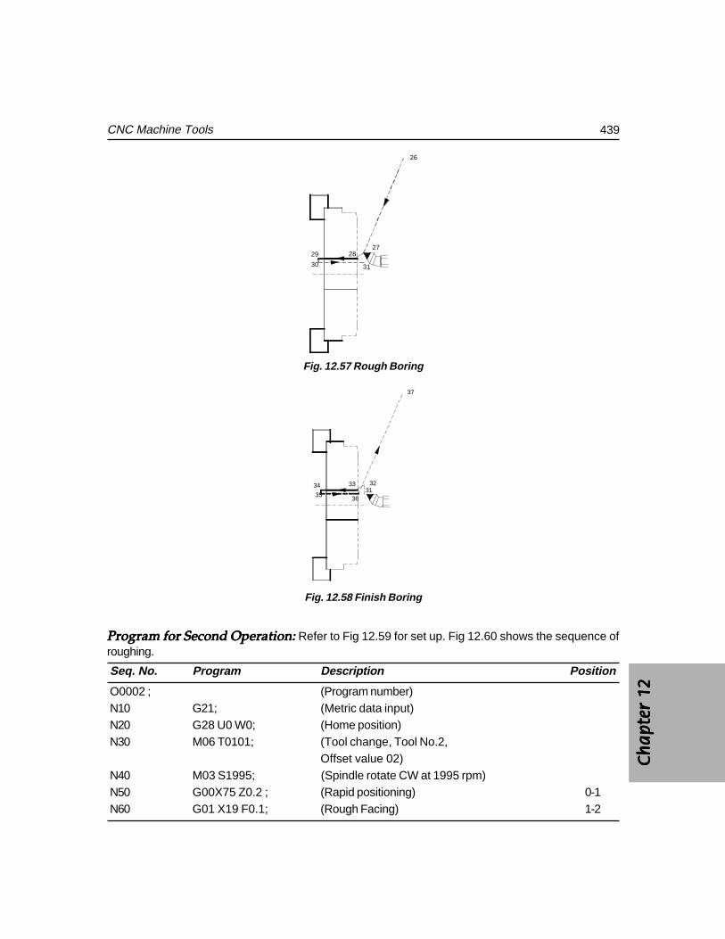
Ch
ap
ter
12C
ha
pte
r 12
Ch
ap
ter
12C
ha
pte
r 12
Ch
ap
ter
12
439CNC Machine Tools
26
272829
30 31
Fig. 12.57 Rough Boring
31323334
3536
37
Fig. 12.58 Finish Boring
Program for Second Operation: Program for Second Operation: Program for Second Operation: Program for Second Operation: Program for Second Operation: Refer to Fig 12.59 for set up. Fig 12.60 shows the sequence ofroughing.
Seq. No. Program Description Position
O0002 ; (Program number)N10 G21; (Metric data input)N20 G28 U0 W0; (Home position)N30 M06 T0101; (Tool change, Tool No.2,
Offset value 02)N40 M03 S1995; (Spindle rotate CW at 1995 rpm)N50 G00X75 Z0.2 ; (Rapid positioning) 0-1N60 G01 X19 F0.1; (Rough Facing) 1-2
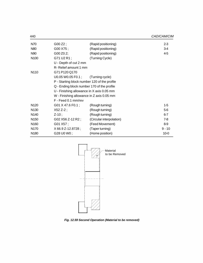
440 CAD/CAM/CIM
N70 G00 Z2 ; (Rapid positioning) 2-3N80 G00 X75 ; (Rapid positioning) 3-4N90 G00 Z0.2; (Rapid positioning) 4-5N100 G71 U2 R1 ; (Turning Cycle)
U - Depth of cut 2 mmR- Relief amount 1 mm
N110 G71 P120 Q170U0.05 W0.05 F0.1 ; (Turning cycle)P - Starting block number 120 of the profileQ - Ending block number 170 of the profileU - Finishing allowance in X axis 0.05 mmW - Finishing allowance in Z axis 0.05 mmF - Feed 0.1 mm/rev
N120 G01 X 47.6 F0.1 ; (Rough turning) 1-5N130 X52 Z-2 ; (Rough turning) 5-6N140 Z-10 ; (Rough turning) 6-7N150 G02 X56 Z-12 R2 ; (Circular interpolation) 7-8N160 G01 X57 ; (Feed Movement) 8-9N170 X 66.9 Z-12.8728 ; (Taper turning) 9 - 10N180 G28 U0 W0 ; (Home position) 10-0
Materialto be Removed
Fig. 12.59 Second Operation (Material to be removed)
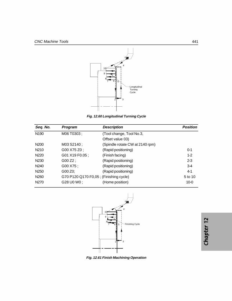
Ch
ap
ter
12C
ha
pte
r 12
Ch
ap
ter
12C
ha
pte
r 12
Ch
ap
ter
12
441CNC Machine Tools
0
1
2 3
4
5678
9
10
LongitudinalTurning Cycle
Fig. 12.60 Longitudinal Turning Cycle
Seq. No. Program Description Position
N190 M06 T0303 ; (Tool change, Tool No.3,Offset value 03)
N200 M03 S2140 ; (Spindle rotate CW at 2140 rpm)N210 G00 X75 Z0 ; (Rapid positioning) 0-1N220 G01 X19 F0.05 ; (Finish facing) 1-2N230 G00 Z2 ; (Rapid positioning) 2-3N240 G00 X75 ; (Rapid positioning) 3-4N250 G00 Z0; (Rapid positioning) 4-1N260 G70 P120 Q170 F0,05 ; (Finishing cycle) 5 to 10N270 G28 U0 W0 ; (Home position) 10-0
0
1
2 3
4
5678
9
10
Finishing Cycle
Fig. 12.61 Finish Machining Operation
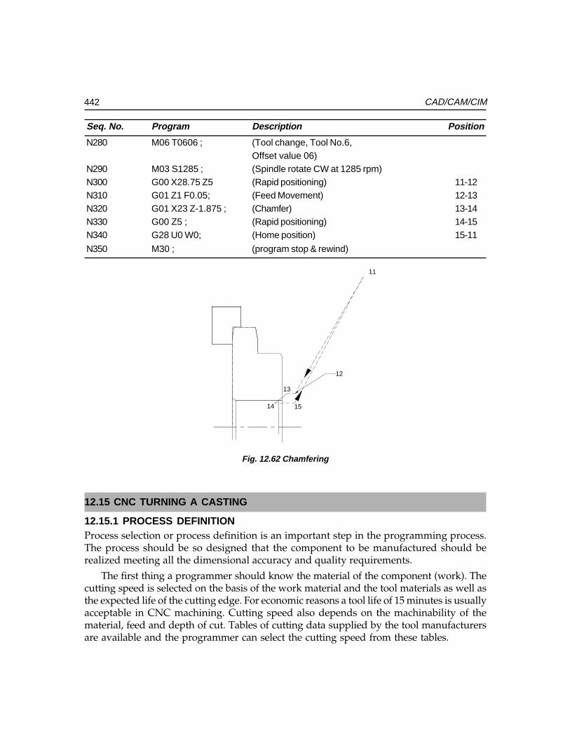
442 CAD/CAM/CIM
Seq. No. Program Description Position
N280 M06 T0606 ; (Tool change, Tool No.6,Offset value 06)
N290 M03 S1285 ; (Spindle rotate CW at 1285 rpm)N300 G00 X28.75 Z5 (Rapid positioning) 11-12N310 G01 Z1 F0.05; (Feed Movement) 12-13N320 G01 X23 Z-1.875 ; (Chamfer) 13-14N330 G00 Z5 ; (Rapid positioning) 14-15N340 G28 U0 W0; (Home position) 15-11
N350 M30 ; (program stop & rewind)
11
13
14 15
12
Fig. 12.62 Chamfering
12.15 CNC TURNING A CASTING
12.15.1 PROCESS DEFINITIONProcess selection or process definition is an important step in the programming process.The process should be so designed that the component to be manufactured should berealized meeting all the dimensional accuracy and quality requirements.
The first thing a programmer should know the material of the component (work). Thecutting speed is selected on the basis of the work material and the tool materials as well asthe expected life of the cutting edge. For economic reasons a tool life of 15 minutes is usuallyacceptable in CNC machining. Cutting speed also depends on the machinability of thematerial, feed and depth of cut. Tables of cutting data supplied by the tool manufacturersare available and the programmer can select the cutting speed from these tables.
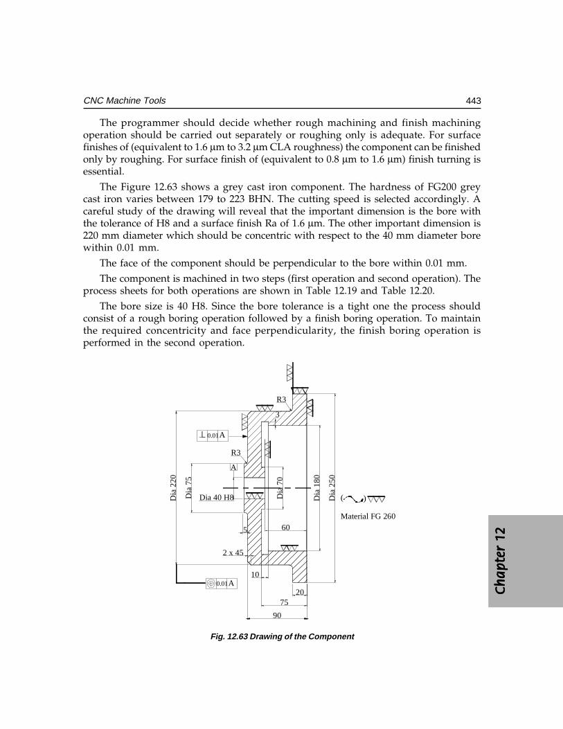
Ch
ap
ter
12C
ha
pte
r 12
Ch
ap
ter
12C
ha
pte
r 12
Ch
ap
ter
12
443CNC Machine Tools
The programmer should decide whether rough machining and finish machiningoperation should be carried out separately or roughing only is adequate. For surfacefinishes of (equivalent to 1.6 µm to 3.2 µm CLA roughness) the component can be finishedonly by roughing. For surface finish of (equivalent to 0.8 µm to 1.6 µm) finish turning isessential.
The Figure 12.63 shows a grey cast iron component. The hardness of FG200 greycast iron varies between 179 to 223 BHN. The cutting speed is selected accordingly. Acareful study of the drawing will reveal that the important dimension is the bore withthe tolerance of H8 and a surface finish Ra of 1.6 µm. The other important dimension is220 mm diameter which should be concentric with respect to the 40 mm diameter borewithin 0.01 mm.
The face of the component should be perpendicular to the bore within 0.01 mm.
The component is machined in two steps (first operation and second operation). Theprocess sheets for both operations are shown in Table 12.19 and Table 12.20.
The bore size is 40 H8. Since the bore tolerance is a tight one the process shouldconsist of a rough boring operation followed by a finish boring operation. To maintainthe required concentricity and face perpendicularity, the finish boring operation isperformed in the second operation.
Dia
70
Dia
180
Dia
250
R3
2075
90
2 x 45
R3
Dia 40 H8
A
Dia
75
A0.01
5
Dia
220
0.01A
60
3
10
( )
Material FG 260
Fig. 12.63 Drawing of the Component
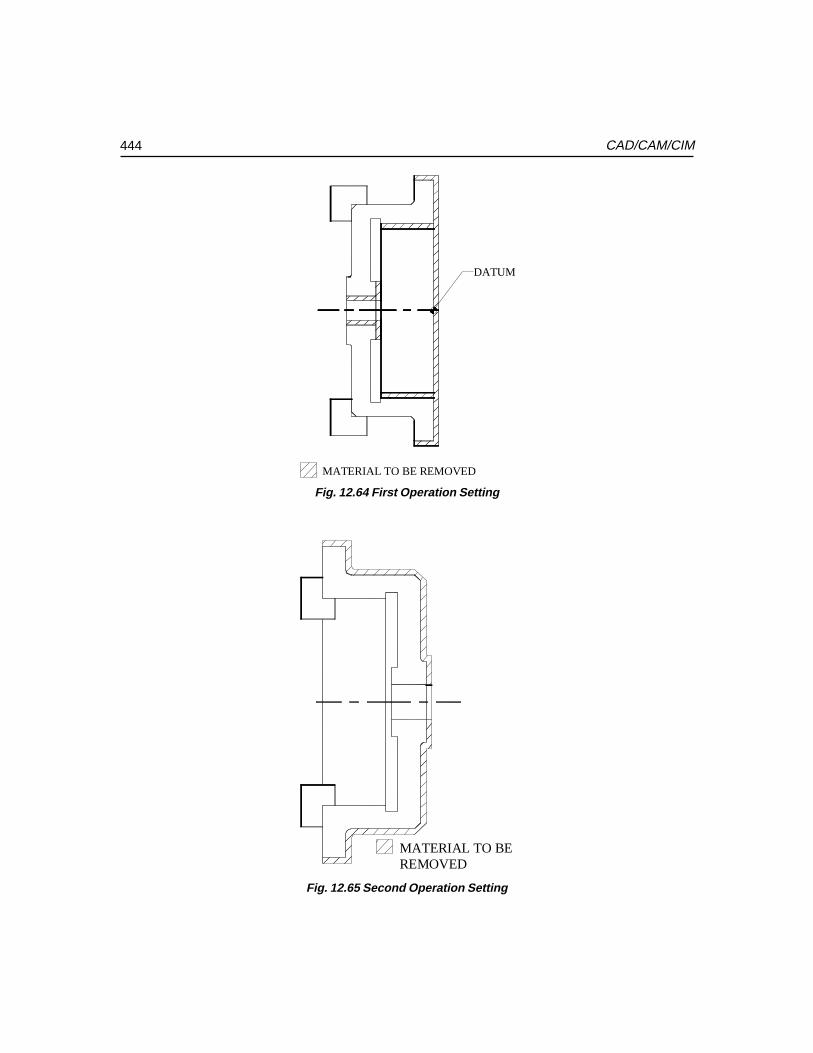
444 CAD/CAM/CIM
MATERIAL TO BE REMOVED
DATUM
Fig. 12.64 First Operation Setting
MATERIAL TO BE REMOVED
Fig. 12.65 Second Operation Setting
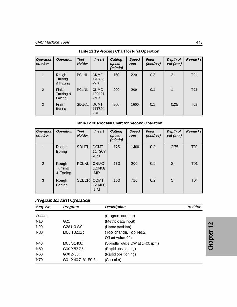
Ch
ap
ter
12C
ha
pte
r 12
Ch
ap
ter
12C
ha
pte
r 12
Ch
ap
ter
12
445CNC Machine Tools
Table 12.19 Process Chart for First Operation
Operation Operation Tool Insert Cutting Speed Feed Depth of Remarksnumber Holder speed rpm (mm/rev) cut (mm)
(m/min)
1 Rough PCLNL CNMG 160 220 0.2 2 T01Turning 120408& Facing -MR
2 Finish PCLNL CNMG 200 260 0.1 1 T03Turning & 120404Facing - MR
3 Finish SDUCL DCMT 200 1600 0.1 0.25 T02Boring 11T304
- UF
Table 12.20 Process Chart for Second Operation
Operation Operation Tool Insert Cutting Speed Feed Depth of Remarksnumber Holder speed rpm (mm/rev) cut (mm)
(m/min)
1 Rough SDUCL DCMT 175 1400 0.3 2.75 T02Boring 11T308
-UM
2 Rough PCLNL CNMG 160 200 0.2 3 T01Turning 120408& Facing -MR
3 Rough SCLCR CCMT 160 720 0.2 3 T04Facing 120408
-UM
Program for First OperationProgram for First OperationProgram for First OperationProgram for First OperationProgram for First OperationSeq. No. Program Description Position
O0001; (Program number)N10 G21 (Metric data input)N20 G28 U0 W0; (Home position)N30 M06 T0202 ; (Tool change, Tool No.2,
Offset value 02)N40 M03 S1400; (Spindle rotate CW at 1400 rpm)N50 G00 X53 Z5 ; (Rapid positioning)N60 G00 Z-55; (Rapid positioning)N70 G01 X40 Z-61 F0.2 ; (Chamfer)
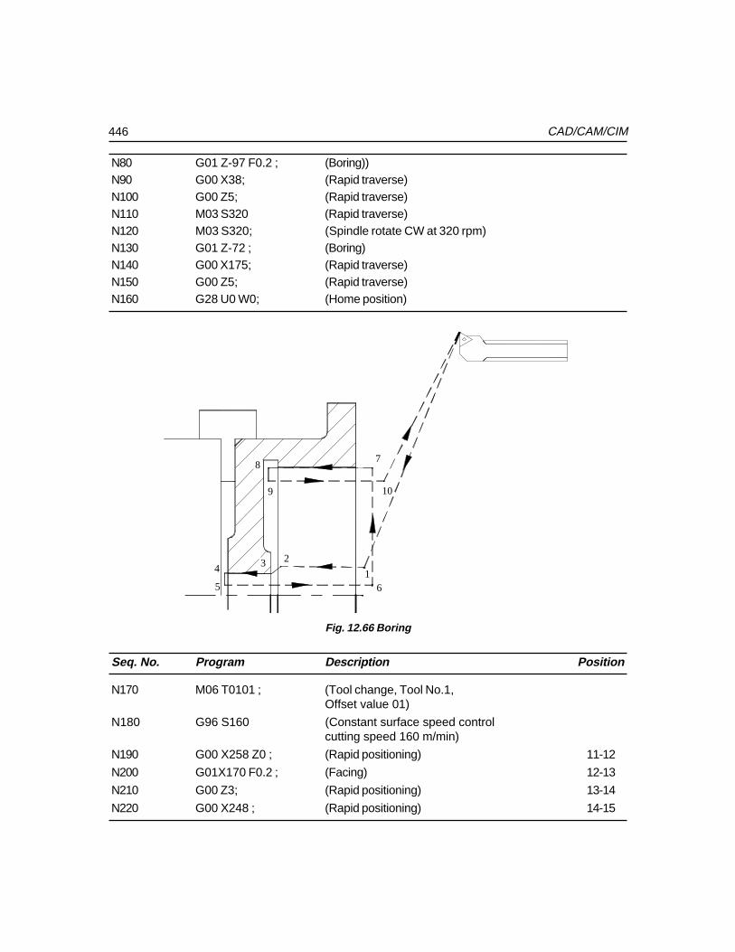
446 CAD/CAM/CIM
N80 G01 Z-97 F0.2 ; (Boring))N90 G00 X38; (Rapid traverse)N100 G00 Z5; (Rapid traverse)N110 M03 S320 (Rapid traverse)N120 M03 S320; (Spindle rotate CW at 320 rpm)N130 G01 Z-72 ; (Boring)N140 G00 X175; (Rapid traverse)N150 G00 Z5; (Rapid traverse)N160 G28 U0 W0; (Home position)
1
234
5 6
78
9 10
Fig. 12.66 Boring
Seq. No. Program Description Position
N170 M06 T0101 ; (Tool change, Tool No.1,Offset value 01)
N180 G96 S160 (Constant surface speed controlcutting speed 160 m/min)
N190 G00 X258 Z0 ; (Rapid positioning) 11-12
N200 G01X170 F0.2 ; (Facing) 12-13
N210 G00 Z3; (Rapid positioning) 13-14
N220 G00 X248 ; (Rapid positioning) 14-15
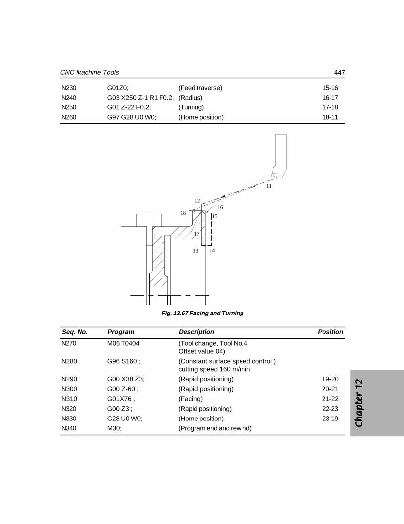
Ch
ap
ter
12C
ha
pte
r 12
Ch
ap
ter
12C
ha
pte
r 12
Ch
ap
ter
12
447CNC Machine Tools
N230 G01Z0; (Feed traverse) 15-16
N240 G03 X250 Z-1 R1 F0.2; (Radius) 16-17
N250 G01 Z-22 F0.2; (Turning) 17-18
N260 G97 G28 U0 W0; (Home position) 18-11
11
12
13 14
1518
17
16
Fig. 12.67 Facing and Turning
Seq. No. Program Description Position
N270 M06 T0404 (Tool change, Tool No.4Offset value 04)
N280 G96 S160 ; (Constant surface speed control )cutting speed 160 m/min
N290 G00 X38 Z3; (Rapid positioning) 19-20
N300 G00 Z-60 ; (Rapid positioning) 20-21
N310 G01X76 ; (Facing) 21-22
N320 G00 Z3 ; (Rapid positioning) 22-23
N330 G28 U0 W0; (Home position) 23-19
N340 M30; (Program end and rewind)
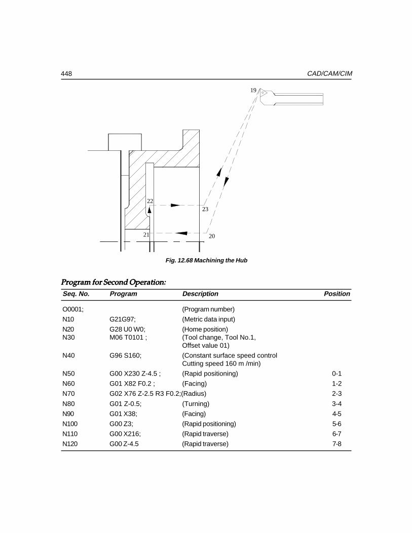
448 CAD/CAM/CIM
19
2021
2223
Fig. 12.68 Machining the Hub
Program for Second Operation:Program for Second Operation:Program for Second Operation:Program for Second Operation:Program for Second Operation:
Seq. No. Program Description Position
O0001; (Program number)
N10 G21G97; (Metric data input)
N20 G28 U0 W0; (Home position)N30 M06 T0101 ; (Tool change, Tool No.1,
Offset value 01)
N40 G96 S160; (Constant surface speed controlCutting speed 160 m /min)
N50 G00 X230 Z-4.5 ; (Rapid positioning) 0-1
N60 G01 X82 F0.2 ; (Facing) 1-2
N70 G02 X76 Z-2.5 R3 F0.2;(Radius) 2-3
N80 G01 Z-0.5; (Turning) 3-4
N90 G01 X38; (Facing) 4-5
N100 G00 Z3; (Rapid positioning) 5-6
N110 G00 X216; (Rapid traverse) 6-7
N120 G00 Z-4.5 (Rapid traverse) 7-8
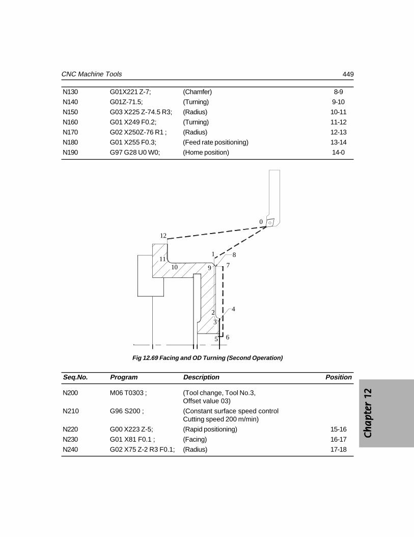
Ch
ap
ter
12C
ha
pte
r 12
Ch
ap
ter
12C
ha
pte
r 12
Ch
ap
ter
12
449CNC Machine Tools
N130 G01X221 Z-7; (Chamfer) 8-9
N140 G01Z-71.5; (Turning) 9-10
N150 G03 X225 Z-74.5 R3; (Radius) 10-11
N160 G01 X249 F0.2; (Turning) 11-12
N170 G02 X250Z-76 R1 ; (Radius) 12-13
N180 G01 X255 F0.3; (Feed rate positioning) 13-14
N190 G97 G28 U0 W0; (Home position) 14-0
0
1
2
3
5 6
791011
12
4
8
Fig 12.69 Facing and OD Turning (Second Operation)
Seq.No. Program Description Position
N200 M06 T0303 ; (Tool change, Tool No.3,Offset value 03)
N210 G96 S200 ; (Constant surface speed controlCutting speed 200 m/min)
N220 G00 X223 Z-5; (Rapid positioning) 15-16
N230 G01 X81 F0.1 ; (Facing) 16-17
N240 G02 X75 Z-2 R3 F0.1; (Radius) 17-18
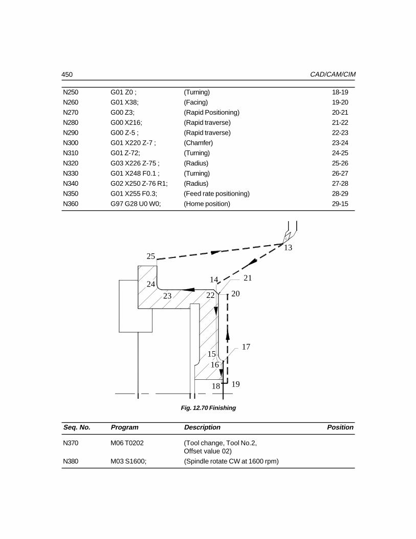
450 CAD/CAM/CIM
N250 G01 Z0 ; (Turning) 18-19
N260 G01 X38; (Facing) 19-20
N270 G00 Z3; (Rapid Positioning) 20-21
N280 G00 X216; (Rapid traverse) 21-22
N290 G00 Z-5 ; (Rapid traverse) 22-23
N300 G01 X220 Z-7 ; (Chamfer) 23-24
N310 G01 Z-72; (Turning) 24-25
N320 G03 X226 Z-75 ; (Radius) 25-26
N330 G01 X248 F0.1 ; (Turning) 26-27
N340 G02 X250 Z-76 R1; (Radius) 27-28
N350 G01 X255 F0.3; (Feed rate positioning) 28-29
N360 G97 G28 U0 W0; (Home position) 29-15
13
14
1516
17
18 19
20
21
2223
24
25
Fig. 12.70 Finishing
Seq. No. Program Description Position
N370 M06 T0202 (Tool change, Tool No.2,Offset value 02)
N380 M03 S1600; (Spindle rotate CW at 1600 rpm)
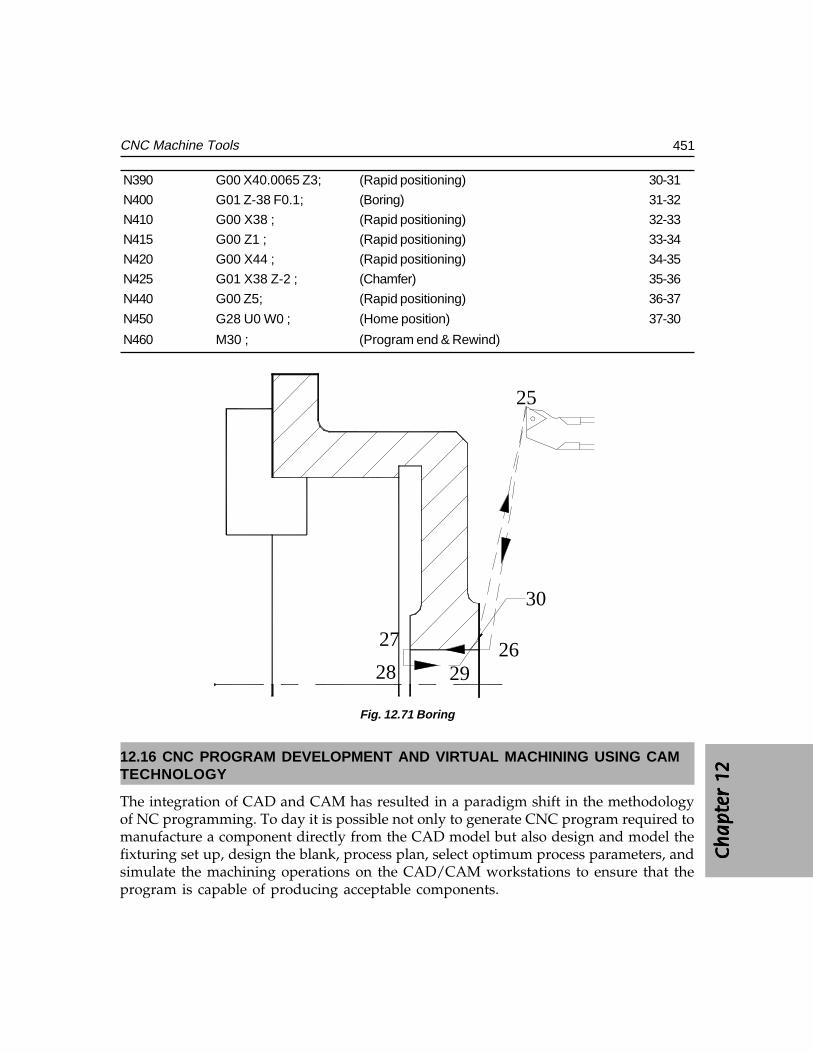
Ch
ap
ter
12C
ha
pte
r 12
Ch
ap
ter
12C
ha
pte
r 12
Ch
ap
ter
12
451CNC Machine Tools
N390 G00 X40.0065 Z3; (Rapid positioning) 30-31
N400 G01 Z-38 F0.1; (Boring) 31-32
N410 G00 X38 ; (Rapid positioning) 32-33
N415 G00 Z1 ; (Rapid positioning) 33-34
N420 G00 X44 ; (Rapid positioning) 34-35
N425 G01 X38 Z-2 ; (Chamfer) 35-36
N440 G00 Z5; (Rapid positioning) 36-37
N450 G28 U0 W0 ; (Home position) 37-30
N460 M30 ; (Program end & Rewind)
25
2627
28 29
30
Fig. 12.71 Boring
12.16 CNC PROGRAM DEVELOPMENT AND VIRTUAL MACHINING USING CAMTECHNOLOGY
The integration of CAD and CAM has resulted in a paradigm shift in the methodologyof NC programming. To day it is possible not only to generate CNC program required tomanufacture a component directly from the CAD model but also design and model thefixturing set up, design the blank, process plan, select optimum process parameters, andsimulate the machining operations on the CAD/CAM workstations to ensure that theprogram is capable of producing acceptable components.
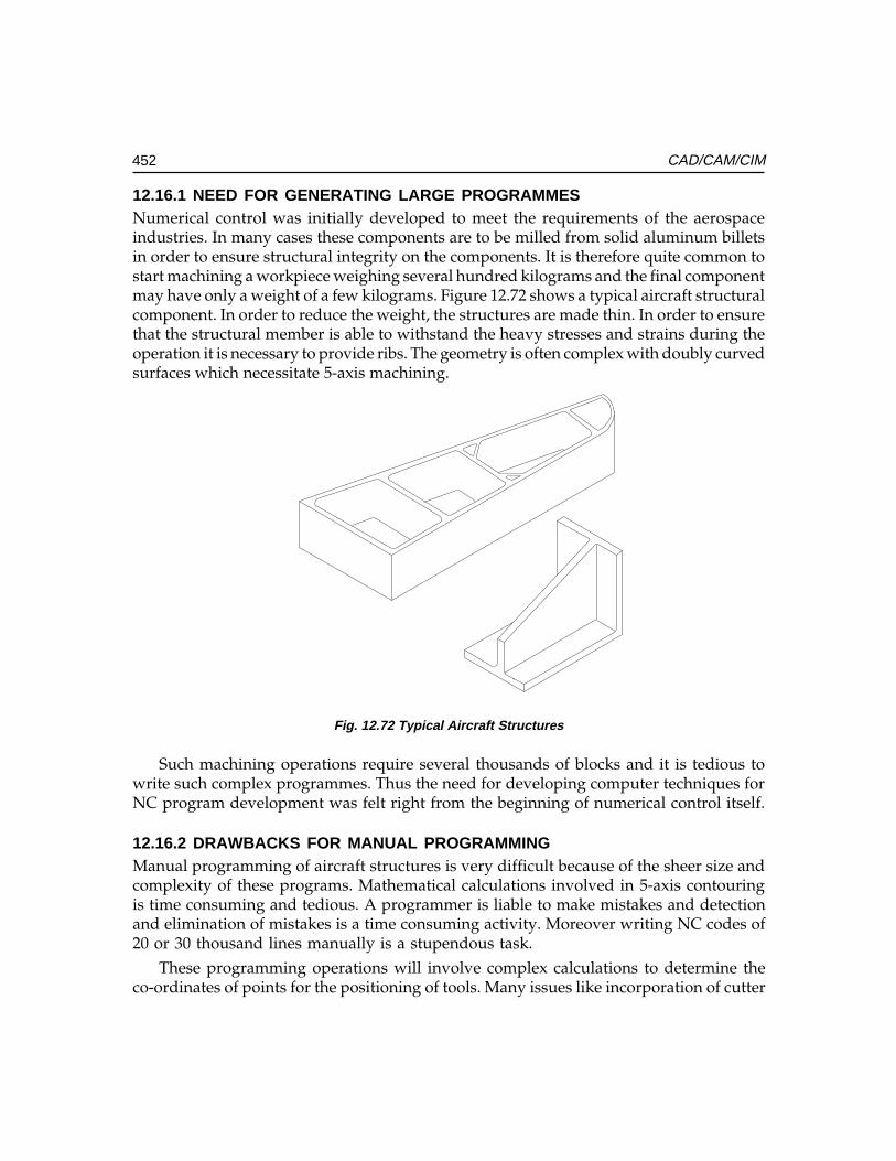
452 CAD/CAM/CIM
12.16.1 NEED FOR GENERATING LARGE PROGRAMMESNumerical control was initially developed to meet the requirements of the aerospaceindustries. In many cases these components are to be milled from solid aluminum billetsin order to ensure structural integrity on the components. It is therefore quite common tostart machining a workpiece weighing several hundred kilograms and the final componentmay have only a weight of a few kilograms. Figure 12.72 shows a typical aircraft structuralcomponent. In order to reduce the weight, the structures are made thin. In order to ensurethat the structural member is able to withstand the heavy stresses and strains during theoperation it is necessary to provide ribs. The geometry is often complex with doubly curvedsurfaces which necessitate 5-axis machining.
Fig. 12.72 Typical Aircraft Structures
Such machining operations require several thousands of blocks and it is tedious towrite such complex programmes. Thus the need for developing computer techniques forNC program development was felt right from the beginning of numerical control itself.
12.16.2 DRAWBACKS FOR MANUAL PROGRAMMINGManual programming of aircraft structures is very difficult because of the sheer size andcomplexity of these programs. Mathematical calculations involved in 5-axis contouringis time consuming and tedious. A programmer is liable to make mistakes and detectionand elimination of mistakes is a time consuming activity. Moreover writing NC codes of20 or 30 thousand lines manually is a stupendous task.
These programming operations will involve complex calculations to determine theco-ordinates of points for the positioning of tools. Many issues like incorporation of cutter
Ch
ap
ter
12C
ha
pte
r 12
Ch
ap
ter
12C
ha
pte
r 12
Ch
ap
ter
12
453CNC Machine Tools
diameter compensation make these calculations very involved. Further, errors ifundetected will result in enormous wastage in terms of materials and time resulting inover runs in project time and cost.
12.16.3 DEVELOPMENT OF COMPUTER AIDED MANUFACTURINGBecause of the reasons mentioned in the previous section the need for computer tools forprogram development was felt early in the history of NC. MIT developed APT in 50’s andfor a long time APT used to be the most commonly used software for computer aided NCprogramming. APT (acronym for AAAAAutomatic PPPPPositioning of TTTTTools) was originally developedby Massachusetts Institute of Technology . Later Illinois Institute of Technology ResearchInstitute, Chicago developed APT further. An organization called CAM-I was carryingout developments in APT after IITRI . Depending on the computer on which APT wasimplemented there were several versions of APT namely, UNIAPT (Univac Computer),NELAPT (National Engineering Laboratory), FAPT (Fujitsu Fanuc), ADAPT (IBM),AUTOSPOT (IBM), CINTURN (Cincinnati Milacron), COMPACT-II (Manufacturing DataSystems International), GENTURN (General Electric), MILTURN (Metal Institute,Netherlands), NEL (Ferranti), SPLIT (Sundstrand), EXAPT (Technische Hochschule,Aachen) etc. Several other computer aided programming softwares were also available tothe programmers in ‘60s and ‘70s.
The approach to computer aided part programming in these softwares is as follows:
i. Definition of geometry (Geometry statements):Definition of geometry (Geometry statements):Definition of geometry (Geometry statements):Definition of geometry (Geometry statements):Definition of geometry (Geometry statements): The geometry of the componentis defined with statements like POINT, LINE, PLANE, CIRCLE, CYLINDER,ELLIPSE, VECTOR, CONIC, TABCYL (Ta BULATED CYLINDER) ETC. Usingthese statements the geometry of the component can be completely defined.
ii. Motion statements:Motion statements:Motion statements:Motion statements:Motion statements: The tool assumed to around the workpiece to carry out themachining operations. Commands like GO, GODLTA, GOTO, OFFSET, TLLFT,GOLFT, GOUP, TLNDON, etc., are used to define the tool movements.
iii. Post processor statements:Post processor statements:Post processor statements:Post processor statements:Post processor statements: It is necessary to specify the cutter details, spindlespeed, feed rate, tolerances etc., and these are included in the post processorstatements. FEDRAT, COOLNT, CUTTER, TOLER, etc., were the typical post-processing statements.
The APT processor will create a cutter location data file (CL Data file) which isbasically a text file containing the co-ordinates of the points to be visited by the tool. Itis necessary to modify this and convert it into a NC program to suit a particularcombination of a machine tool and a control system. Since the specifications andcapabilities of machine tools and the features of the control systems vary widely it isessential to develop separate post processors to create NC programs for each machinetool and control system combination.
APT was the forerunner of the present CAD/CAM technology. The developmentsin CAD and CAM has made this approach of program creation obsolete. To day the
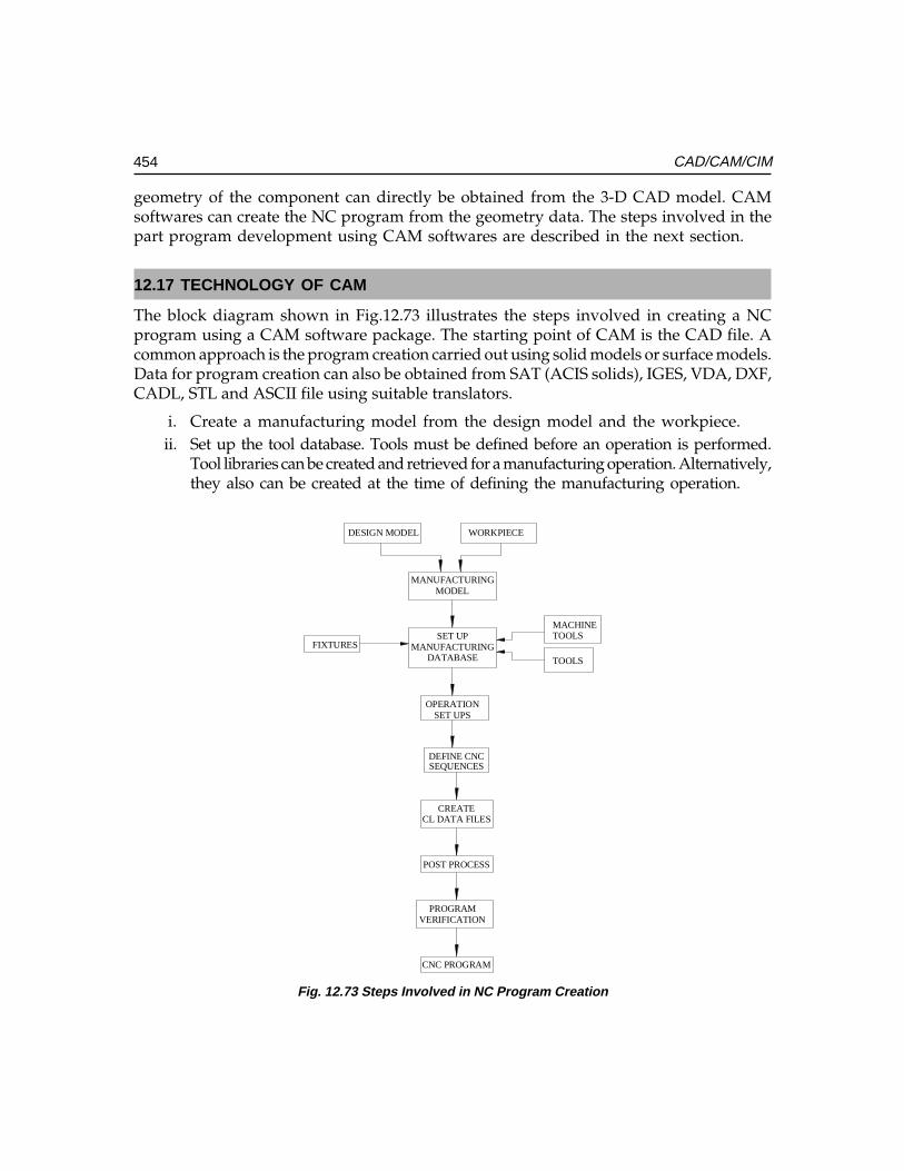
454 CAD/CAM/CIM
geometry of the component can directly be obtained from the 3-D CAD model. CAMsoftwares can create the NC program from the geometry data. The steps involved in thepart program development using CAM softwares are described in the next section.
12.17 TECHNOLOGY OF CAM
The block diagram shown in Fig.12.73 illustrates the steps involved in creating a NCprogram using a CAM software package. The starting point of CAM is the CAD file. Acommon approach is the program creation carried out using solid models or surface models.Data for program creation can also be obtained from SAT (ACIS solids), IGES, VDA, DXF,CADL, STL and ASCII file using suitable translators.
i. Create a manufacturing model from the design model and the workpiece.ii. Set up the tool database. Tools must be defined before an operation is performed.
Tool libraries can be created and retrieved for a manufacturing operation. Alternatively,they also can be created at the time of defining the manufacturing operation.
CNC PROGRAM
MACHINETOOLS
TOOLS
FIXTURES
DESIGN MODEL WORKPIECE
MANUFACTURINGMODEL
SET UPMANUFACTURING
DATABASE
OPERATIONSET UPS
DEFINE CNCSEQUENCES
CREATECL DATA FILES
POST PROCESS
PROGRAMVERIFICATION
Fig. 12.73 Steps Involved in NC Program Creation
Ch
ap
ter
12C
ha
pte
r 12
Ch
ap
ter
12C
ha
pte
r 12
Ch
ap
ter
12
455CNC Machine Tools
iii. Select the set up for the machining operation. A component may require morethan one set up to complete the machining operation.
iv. Fixtures are necessary for each set up. Fixtures can be displayed along with theworkpiece. This is to ensure that the path of the tools does not interfere with thetools. Fixtures consist of the locating and clamping elements to hold the workpieceon the machine table during the machining operation. In the case of a turningoperation appropriate chucking devices should be used. Standard fixture elementscan be created as a library of parts and assembled before the manufacturingoperation is commenced. These are also available as standard libraries.
v. Create a machinability database. Parameters like spindle speed and feed rate canbe selected from the machinability database.
vi. Create the manufacturing operations to generate the CL data. As eachmanufacturing operation takes place, material is removed from the workpiece tosimulate the actual manufacturing operation. This simulation is enhanced by thetool path being displayed for each operation.
vii. If needed the CL data can be modified by modifying the operation parametersor by editing the CL data file.
viii. Create a manufacturing route sheet at the end of the manufacturing session.ix. Post-process the CL file to create the NC program.There are several popular CAM packages available today. Some of them are listed
below:
PRO/ManufacturingCVCNCI-DEAS generative ManufacturingUG - ManufacturingSurf CAMVirtual GibbsEdge CAMProspectorMaster CAMCimatron
The next section describes in detail the procedure of creating a NC program using aCAM software.
12.18 PROCEDURE OF CAM
The CAD model represents the finished product. This is used as a basis for themanufacturing operations. Features, surfaces and edges are selected on the design modelas references for each manufacturing operation. Referencing the geometry of the designmodel sets up parametric relationship between the design model and the workpiece.
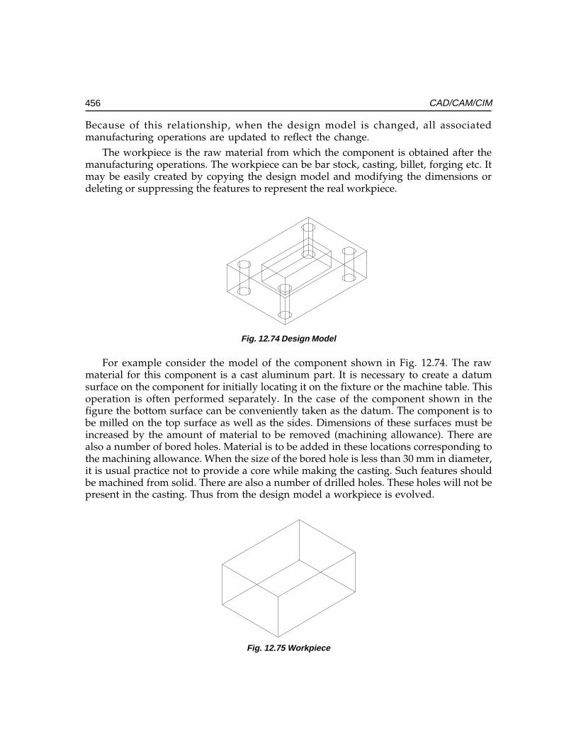
456 CAD/CAM/CIM
Because of this relationship, when the design model is changed, all associatedmanufacturing operations are updated to reflect the change.
The workpiece is the raw material from which the component is obtained after themanufacturing operations. The workpiece can be bar stock, casting, billet, forging etc. Itmay be easily created by copying the design model and modifying the dimensions ordeleting or suppressing the features to represent the real workpiece.
Fig. 12.74 Design Model
For example consider the model of the component shown in Fig. 12.74. The rawmaterial for this component is a cast aluminum part. It is necessary to create a datumsurface on the component for initially locating it on the fixture or the machine table. Thisoperation is often performed separately. In the case of the component shown in thefigure the bottom surface can be conveniently taken as the datum. The component is tobe milled on the top surface as well as the sides. Dimensions of these surfaces must beincreased by the amount of material to be removed (machining allowance). There arealso a number of bored holes. Material is to be added in these locations corresponding tothe machining allowance. When the size of the bored hole is less than 30 mm in diameter,it is usual practice not to provide a core while making the casting. Such features shouldbe machined from solid. There are also a number of drilled holes. These holes will not bepresent in the casting. Thus from the design model a workpiece is evolved.
Fig. 12.75 Workpiece
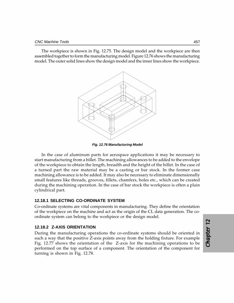
Ch
ap
ter
12C
ha
pte
r 12
Ch
ap
ter
12C
ha
pte
r 12
Ch
ap
ter
12
457CNC Machine Tools
The workpiece is shown in Fig. 12.75. The design model and the workpiece are thenassembled together to form the manufacturing model. Figure 12.76 shows the manufacturingmodel. The outer solid lines show the design model and the inner lines show the workpiece.
Fig. 12.76 Manufacturing Model
In the case of aluminum parts for aerospace applications it may be necessary tostart manufacturing from a billet. The machining allowances to be added to the envelopeof the workpiece to obtain the length, breadth and the height of the billet. In the case ofa turned part the raw material may be a casting or bar stock. In the former casemachining allowance is to be added. It may also be necessary to eliminate dimensionallysmall features like threads, grooves, fillets, chamfers, holes etc., which can be createdduring the machining operation. In the case of bar stock the workpiece is often a plaincylindrical part.
12.18.1 SELECTING CO-ORDINATE SYSTEMCo-ordinate systems are vital components in manufacturing. They define the orientationof the workpiece on the machine and act as the origin of the CL data generation. The co-ordinate system can belong to the workpiece or the design model.
12.18.2 Z-AXIS ORIENTATIONDuring the manufacturing operations the co-ordinate systems should be oriented insuch a way that the positive Z-axis points away from the holding fixture. For exampleFig. 12.77 shows the orientation of the Z-axis for the machining operations to beperformed on the top surface of a component. The orientation of the component forturning is shown in Fig. 12.78.
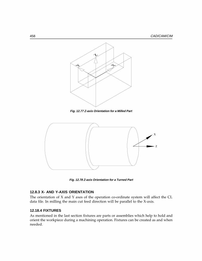
458 CAD/CAM/CIM
Fig. 12.77 Z-axis Orientation for a Milled Part
X
Z
Fig. 12.78 Z-axis Orientation for a Turned Part
12.8.3 X- AND Y-AXIS ORIENTATIONThe orientation of X and Y axes of the operation co-ordinate system will affect the CLdata file. In milling the main cut feed direction will be parallel to the X-axis.
12.18.4 FIXTURESAs mentioned in the last section fixtures are parts or assemblies which help to hold andorient the workpiece during a machining operation. Fixtures can be created as and whenneeded.
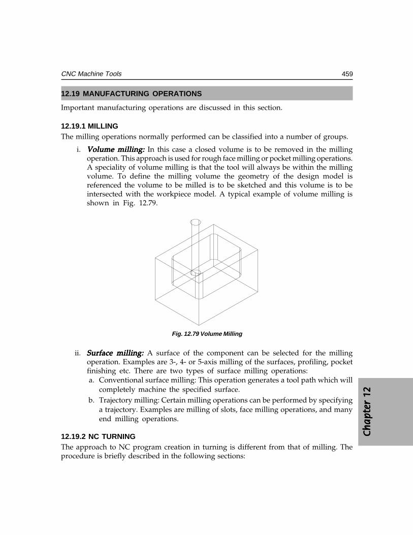
Ch
ap
ter
12C
ha
pte
r 12
Ch
ap
ter
12C
ha
pte
r 12
Ch
ap
ter
12
459CNC Machine Tools
12.19 MANUFACTURING OPERATIONS
Important manufacturing operations are discussed in this section.
12.19.1 MILLINGThe milling operations normally performed can be classified into a number of groups.
i. Volume milling: Volume milling: Volume milling: Volume milling: Volume milling: In this case a closed volume is to be removed in the millingoperation. This approach is used for rough face milling or pocket milling operations.A speciality of volume milling is that the tool will always be within the millingvolume. To define the milling volume the geometry of the design model isreferenced the volume to be milled is to be sketched and this volume is to beintersected with the workpiece model. A typical example of volume milling isshown in Fig. 12.79.
Fig. 12.79 Volume Milling
ii. Surface milling: Surface milling: Surface milling: Surface milling: Surface milling: A surface of the component can be selected for the millingoperation. Examples are 3-, 4- or 5-axis milling of the surfaces, profiling, pocketfinishing etc. There are two types of surface milling operations:a. Conventional surface milling: This operation generates a tool path which will
completely machine the specified surface.b. Trajectory milling: Certain milling operations can be performed by specifying
a trajectory. Examples are milling of slots, face milling operations, and manyend milling operations.
12.19.2 NC TURNINGThe approach to NC program creation in turning is different from that of milling. Theprocedure is briefly described in the following sections:
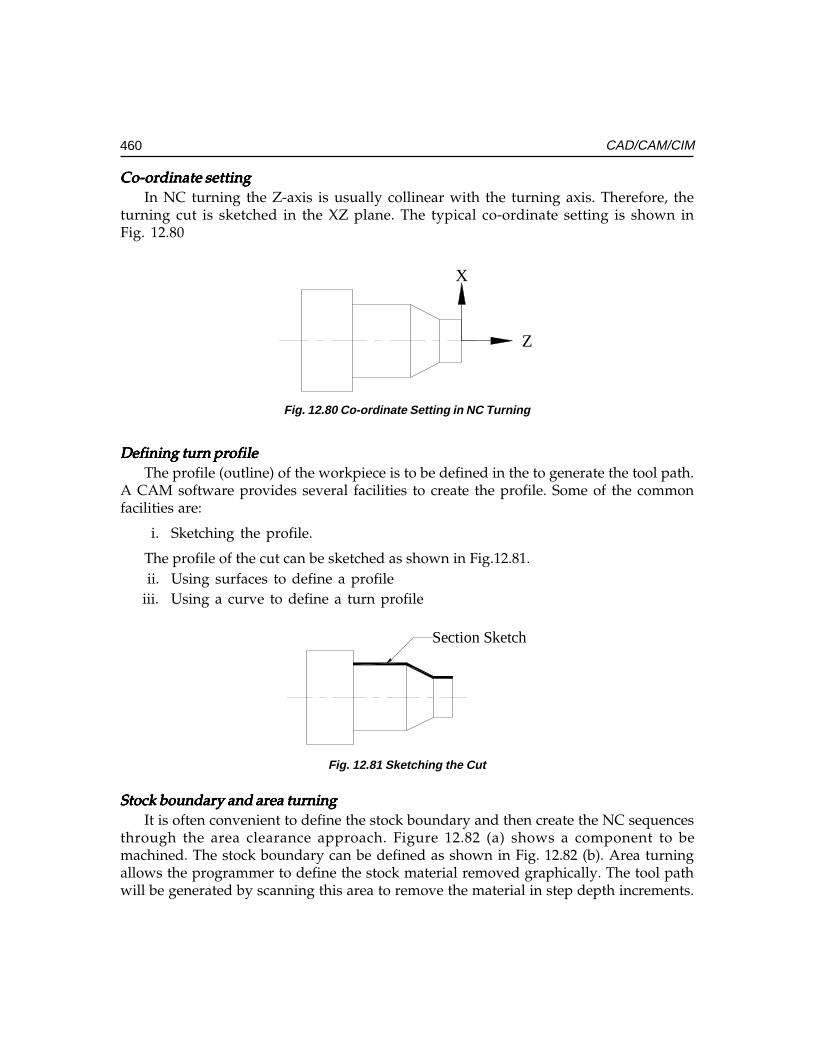
460 CAD/CAM/CIM
Co-ordinate settingCo-ordinate settingCo-ordinate settingCo-ordinate settingCo-ordinate settingIn NC turning the Z-axis is usually collinear with the turning axis. Therefore, the
turning cut is sketched in the XZ plane. The typical co-ordinate setting is shown inFig. 12.80
X
Z
Fig. 12.80 Co-ordinate Setting in NC Turning
Defining turn profileDefining turn profileDefining turn profileDefining turn profileDefining turn profileThe profile (outline) of the workpiece is to be defined in the to generate the tool path.
A CAM software provides several facilities to create the profile. Some of the commonfacilities are:
i. Sketching the profile.
The profile of the cut can be sketched as shown in Fig.12.81. ii. Using surfaces to define a profileiii. Using a curve to define a turn profile
Section Sketch
Fig. 12.81 Sketching the Cut
Stock boundary and area turningStock boundary and area turningStock boundary and area turningStock boundary and area turningStock boundary and area turningIt is often convenient to define the stock boundary and then create the NC sequences
through the area clearance approach. Figure 12.82 (a) shows a component to bemachined. The stock boundary can be defined as shown in Fig. 12.82 (b). Area turningallows the programmer to define the stock material removed graphically. The tool pathwill be generated by scanning this area to remove the material in step depth increments.
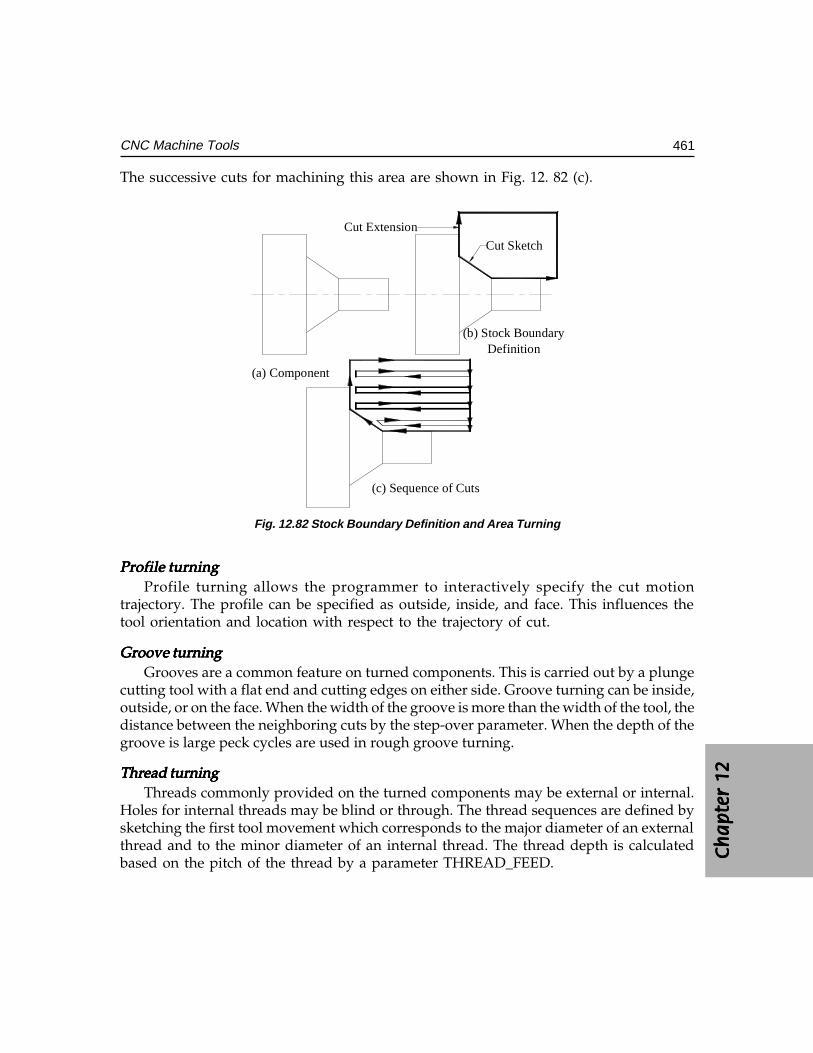
Ch
ap
ter
12C
ha
pte
r 12
Ch
ap
ter
12C
ha
pte
r 12
Ch
ap
ter
12
461CNC Machine Tools
The successive cuts for machining this area are shown in Fig. 12. 82 (c).
Cut Sketch
Cut Extension
(a) Component
(b) Stock BoundaryDefinition
(c) Sequence of Cuts
Fig. 12.82 Stock Boundary Definition and Area Turning
Profile turningProfile turningProfile turningProfile turningProfile turningProfile turning allows the programmer to interactively specify the cut motion
trajectory. The profile can be specified as outside, inside, and face. This influences thetool orientation and location with respect to the trajectory of cut.
Groove turningGroove turningGroove turningGroove turningGroove turningGrooves are a common feature on turned components. This is carried out by a plunge
cutting tool with a flat end and cutting edges on either side. Groove turning can be inside,outside, or on the face. When the width of the groove is more than the width of the tool, thedistance between the neighboring cuts by the step-over parameter. When the depth of thegroove is large peck cycles are used in rough groove turning.
Thread turningThread turningThread turningThread turningThread turningThreads commonly provided on the turned components may be external or internal.
Holes for internal threads may be blind or through. The thread sequences are defined bysketching the first tool movement which corresponds to the major diameter of an externalthread and to the minor diameter of an internal thread. The thread depth is calculatedbased on the pitch of the thread by a parameter THREAD_FEED.
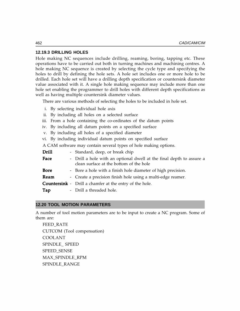
462 CAD/CAM/CIM
12.19.3 DRILLING HOLESHole making NC sequences include drilling, reaming, boring, tapping etc. Theseoperations have to be carried out both in turning machines and machining centres. Ahole making NC sequence is created by selecting the cycle type and specifying theholes to drill by defining the hole sets. A hole set includes one or more hole to bedrilled. Each hole set will have a drilling depth specification or countersink diametervalue associated with it. A single hole making sequence may include more than onehole set enabling the programmer to drill holes with different depth specifications aswell as having multiple countersink diameter values.
There are various methods of selecting the holes to be included in hole set.
i. By selecting individual hole axisii. By including all holes on a selected surface
iii. From a hole containing the co-ordinates of the datum pointsiv. By including all datum points on a specified surfacev. By including all holes of a specified diameter
vi. By including individual datum points on specified surface
A CAM software may contain several types of hole making options.
DrillDrillDrillDrillDrill - Standard, deep, or break chip
FaceFaceFaceFaceFace - Drill a hole with an optional dwell at the final depth to assure aclean surface at the bottom of the hole
BoreBoreBoreBoreBore - Bore a hole with a finish hole diameter of high precision.
ReamReamReamReamReam - Create a precision finish hole using a multi-edge reamer.
CountersinkCountersinkCountersinkCountersinkCountersink - Drill a chamfer at the entry of the hole.
TapTapTapTapTap - Drill a threaded hole.
12.20 TOOL MOTION PARAMETERS
A number of tool motion parameters are to be input to create a NC program. Some ofthem are:
FEED_RATE
CUTCOM (Tool compensation)
COOLANT
SPINDLE_ SPEED
SPEED_SENSE
MAX_SPINDLE_RPM
SPINDLE_RANGE
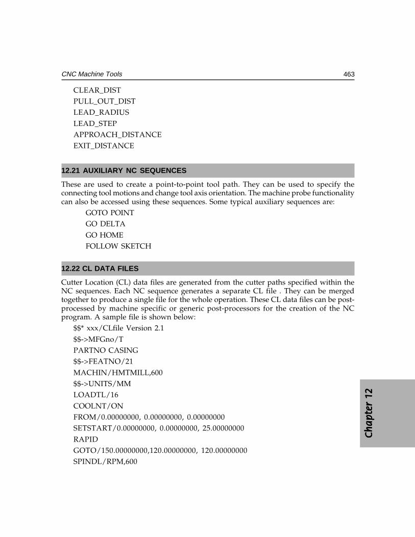
Ch
ap
ter
12C
ha
pte
r 12
Ch
ap
ter
12C
ha
pte
r 12
Ch
ap
ter
12
463CNC Machine Tools
CLEAR_DISTPULL_OUT_DISTLEAD_RADIUSLEAD_STEPAPPROACH_DISTANCEEXIT_DISTANCE
12.21 AUXILIARY NC SEQUENCES
These are used to create a point-to-point tool path. They can be used to specify theconnecting tool motions and change tool axis orientation. The machine probe functionalitycan also be accessed using these sequences. Some typical auxiliary sequences are:
GOTO POINTGO DELTAGO HOMEFOLLOW SKETCH
12.22 CL DATA FILES
Cutter Location (CL) data files are generated from the cutter paths specified within theNC sequences. Each NC sequence generates a separate CL file . They can be mergedtogether to produce a single file for the whole operation. These CL data files can be post-processed by machine specific or generic post-processors for the creation of the NCprogram. A sample file is shown below:
$$* xxx/CLfile Version 2.1$$->MFGno/TPARTNO CASING$$->FEATNO/21MACHIN/HMTMILL,600$$->UNITS/MMLOADTL/16COOLNT/ONFROM/0.00000000, 0.00000000, 0.00000000SETSTART/0.00000000, 0.00000000, 25.00000000RAPIDGOTO/150.00000000,120.00000000, 120.00000000SPINDL/RPM,600
464 CAD/CAM/CIM
FEDRAT/100.000000000,MMPM
CYCLE/DRILL, -75.0, 100.000000000, MMPM
RAPID
GOTO/0.00000000, 0.00000000, 0.00000000
CYCLE/OFF
SPINDL/OFF
$$->END/
FINI
The CL data can be used to display the tool path. This feature will help to locate errorsin the program. The CL data can be edited and modified by rotation, translation, mirroringand scaling.
12.23 NC POST-PROCESSING
The specifications and capabilities of a CNC machine tool will vary from one to another.There area number of manufacturers of CNC control systems and each system will have anumber of versions which will be different with regard to their features. The CL files requireto be modified to generate a NC program from the CL data to suit a machine tool-controlsystem combination. This procedure is called post-processing and CAM softwares usuallyincorporate a software module called generic post-processor for this purpose. Usually theMACHIN statement is used to select the post-processor. A GENER statement will retrieveall the necessary information about the NC machine from the database. The NC programthus created can be stored, listed or simulated on the screen for editing or modification ifneeded, or transferred to a CNC machine using DNC. The NC program can also be checkedusing a software like VERICUT.
12.24 VIRTUAL MACHINING
Creation of programs through CAM software packages is a significant development.This method eliminated the drudgery involved in writing large programs. Errors arereduced and thereby wastage is avoided. However, it is still necessary to prove theprogram as there are so many factors which will influence the acceptability of thecomponent. Gouging is a common problem encountered in creating complex surfaces.Improper programming may remove more material or leave material on the workpieceun-removed. Errors in geometry or tool motion statements may result in a workpiecewhose dimensions after machining may not be acceptable. Dry runs and program proveout on the machine are always time consuming and costly. Hence it is desirable to simulatethe machining program on the computer to verify the program.
Program verification softwares which are now available as a module of CAM softwarepackages are a useful tool to carry out machining on the computer workstation. Since the
Ch
ap
ter
12C
ha
pte
r 12
Ch
ap
ter
12C
ha
pte
r 12
Ch
ap
ter
12
465CNC Machine Tools
machining is carried out in a virtual environment it is called virtual machining. This enablesthe programmers to visualize and modify the program until they are completely satisfiedabout the program. It helps to remove all moves that would have gouged the part. Cutsdeeper than what is required are also detected. The experience of the users of virtualmachining indicates that it is possible to straight away proceed to machining metals andusual problems encountered in machining like tool breakage, collisions and tool wear dueto long run times are avoided. The tool library built into the system enables the programmersto select the tool of the actual shape and dimensions used on the shop floor for simulation.
12.25 SUMMARY
CNC is an important development in manufacturing. A broad overview of the technologywith brief description of some of the recent developments has been presented in the foregoingsections. As a technology which is highly influenced by the developments in microprocessors,microelectronics and information technology, CNC is a still evolving technology. The factorswhich made CNC technology popular in recent years are listed below:
i. With the downsizing of large companies, jobs are subcontracted to smaller shopswhere the use of CNC machines has proved profitable.
ii. Introduction of PC based CNC machines and windows based CAM softwarepackages has made CNC programming and operation user friendly.
iii. CAM software packages make it easy to translate CAD files into CNC programswhich enable users handle sophisticated jobs and schedule work for greaterproductivity and profit.
iv. The cost of CNC machine tools has come down considerably.
QUESTIONS
1. What is the most popular type of drive for CNC machines today?2. Sketch and explain the torque speed characteristics of a spindle drive.3. Why is a gearbox used in the main drive of some CNC machines?4. Why is separate cooling motor used with DC drives?5. List the advantages of AC servomotors over DC servomotors.6. Why is a servomotor used for axes feed drive?7. Why is often a reduction drive using timing belt, employed in feed drives?8. What is the advantage of servomotors with built-in encoders?9. What are the four common types of ball screw mounting arrangements?
10. What are the advantages of Linear Motion guide ways?11. What is the type of plastic insert used in CNC machine sideways?12. What is the purpose of using LM guides or plastic inserts in sideways?13. What is the advantage of using slant bed design for turning machines?
466 CAD/CAM/CIM
14. Why should a brake be used with the X-axis drive in a slant bed lathe?15. What is the principle of operation of a linear motor?16. How is the turret of a CNC lathe indexed?17. What is a bi-directional turret?18. Why are not axial tools kept in adjacent pockets in a tool turret?19. Why is a poly V belt preferred for main drive ?20. What is the advantage of using a linear transducer for feedback measuring?21. What is the advantage of using an absolute measuring system?22. What is the advantage of using an analog measuring system?23. Describe the principle of working of two analog transducers.24. Explain the principle of working of two digital incremental transducers.25. What is a Digital Read Out (DRO) ?26. What is an A/D converter ? Where is it used in a CNC Machine?27. Name three types of bearings used in the mounting of spindles of CNC machines.28. Why is sometimes a spindle oil cooler necessary?29. Is it necessary to keep a CNC machine in an A/C room?30. What type of microprocessors are used in modern CNC systems?31. What is the advantage of multiprocessor CNC system?32. Name three techniques of interpolation.33. Give major specifications of a machining centre.34. Give major specifications of a CNC lathe.35. What are the differences between a CNC lathe and a turning centre?36. What is a typical tool changing time in a modern high speed machining centre?37. How is the slide position referenced?38. What is meant by accuracy?39. What is meant by repeatability?40. How is a CNC machine calibrated?41. What are the following G Functions for a lathe?
G04, G09, G27, G54, G7642.42. What are the following G Functions for a machining centre?
G17, G30, G81, G9943. What are the following M functions for a machining Centre?
M03, M19, M0644. Write and explain the standard format of G01 code in a CNC lathe.45. What is a user macro?46. What is the purpose of a tool pre-setter?
Ch
ap
ter
12C
ha
pte
r 12
Ch
ap
ter
12C
ha
pte
r 12
Ch
ap
ter
12
467CNC Machine Tools
47. What are the D and H codes in a machining centre program?48. How is a tapered thread cut in a machining centre?49. How is a program number designated?50. What is the difference between absolute and incremental programming?51. Specify Nine linear axes as per ISO.52. Specify the different combinations of axes of a 5-axis machining centre.53. What are the axes of a 4 axes machining centre?54. Name the roughing and finishing tool holders in a CNC lathe for turning.55. Name the turning inserts for the above.56. What is the difference between BT taper and ISO taper for machining centres?57. What is the code for tool nose radius compensation in a lathe?58. What is the G code for cutter diameter compensation in milling?59. Describe the types of milling operations available in a CAM software.60. Describe the common tool motion statements available in a CAM software.61. Discuss the stock boundary definition and area clearance in a CAM software.62. What is the speciality of a tapping tool holder in a machining centre? What is
the significance of rigid tapping?63. Why is ceramic tool advantageous than carbide tools in CNC turning?64. Why is a curvic coupling preferred in indexing devices in a CNC machine?65. What are the common types of automatic tool changers?66. Why is a pull stud used in the tool holder of a machining centre?67. How is clamping and unclamping carried out in fixing the tool in the machining
centre?68. Why is a soft jaw used in CNC turning?69. How does an chip conveyor work?70. How is post process metrology carried out in a CNC machine?71. What are the override switches provided on the control panel?72. What is optional stop?73. What is the difference between M00 and M30?74. What is the difference between EIA code and ISO code?75. What are the features of a PC based CNC?76. Name the loading devices used in CNC lathes to improve productivity.77. What is a PLC ?78. How is tool life monitored in a CNC lathe?89. How is tool offset measured in the machine?80. What is the purpose of post processing?
468 CAD/CAM/CIM
81. What is a CL data file?82. What is a universal machining centre?83. Why is a ball nose cutter used in machining of curved surfaces?84. What is background programming ?85. What is meant by conversational programming?86. What is a ‘soft key’ in a CNC panel?87. What is dry run?88. What is simulation?89. What is DNC operation of CNC machines?90. What is radius programming?91. In which G function do you incorporate chamfer command?92. What G code do you use to machine sharp corners?93. What is a canned cycle?94. What are the various methods of selecting a holes on hole set for drilling holes
in a CAM software?95. What are the advantages of using CAM softwares ?96. What is a word address block format?97. Differentiate among design model, workpiece model and manufacturing model
in a CAM software.98. Define the process, write the operation sheet, sketch the set ups and write the
NC program for turning the following components.99. A Cast iron slab of width 600 mm is milled with a face milling cutter of 200 mm
diameter. How many passes are needed to completely mill the entire surface?Sketch the successive paths. What is the step over feed?
100. An aluminum billet of 200 mm width and 600 mm long is milled using a facemilling cutter of 250 mm diameter in one pass. If the air cut distance at thebeginning and at the end of cut is equal to 8 mm estimate the length of cut. Ifthe feed rate used is 800 mm/min calculate the time required for one cut.
101. A 16 mm hole is drilled in a cast iron work piece of 50 mm thick. Calculatethe feed stroke if (a) the depth of the hole is 30 mm and (b) if the hole is a throughhole.
102. Define the process, plan the set up and fixtures, select the tools, prepare theoperation sheets and write/create NC programs for the components givenbelow:
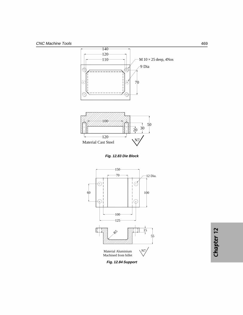
Ch
ap
ter
12C
ha
pte
r 12
Ch
ap
ter
12C
ha
pte
r 12
Ch
ap
ter
12
469CNC Machine Tools
Material Cast Steel
110120140
70
20 3050
100
120
M10x25 deep,4Nos
9 Dia
N7
Fig. 12.83 Die Block
100
Material AluminiumMachined from billet
100
R5
12 Dia.
60
125
N7
150
70
15
55
Fig. 12.84 Support
M 10 × 25 deep, 4Nos
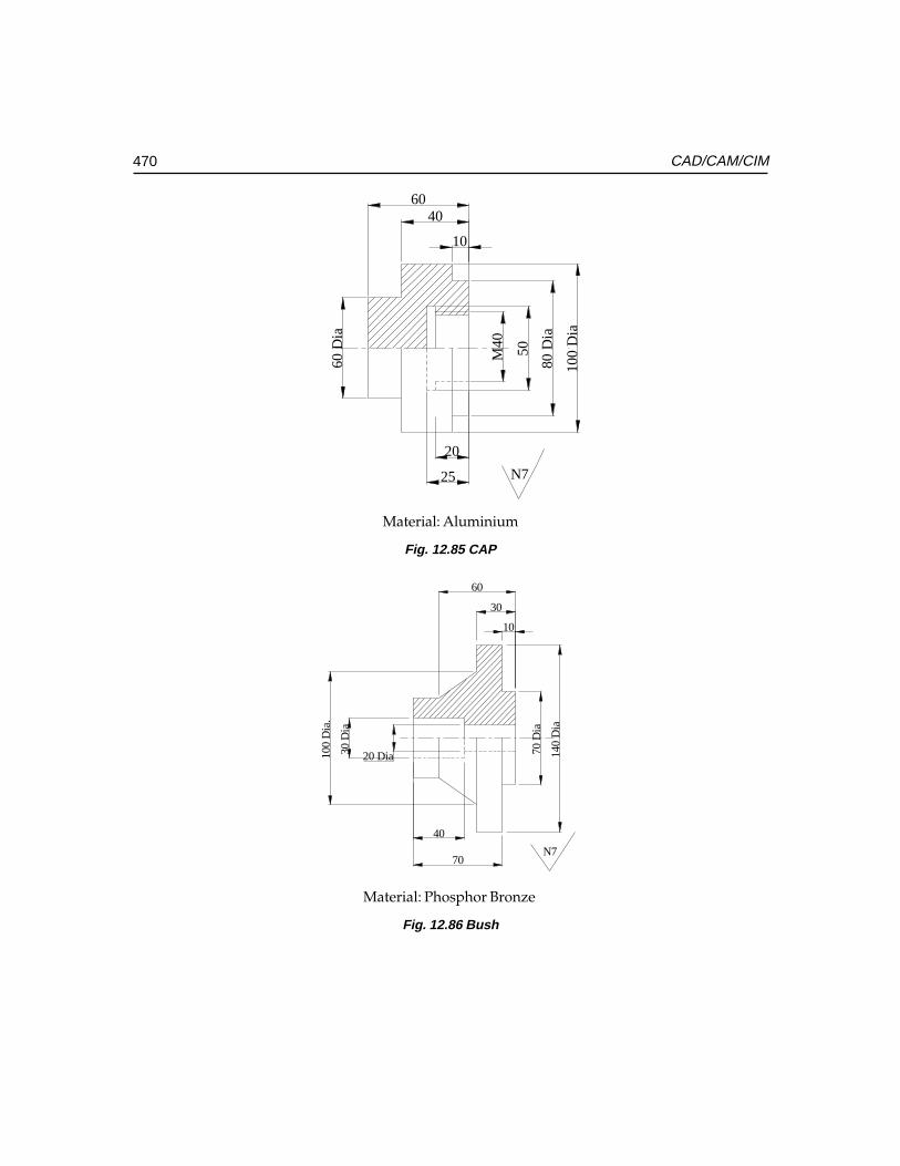
470 CAD/CAM/CIM
Material: Aluminium
Fig. 12.85 CAP
20 Dia30 D
ia
70 D
ia
140
Dia
100
Dia
.
10
30
60
70
40
N7
Fig. 12.86 Bush
6040
10
M40 50
80 D
ia
100
Dia
60 D
ia
25
20
N7
Material: Phosphor Bronze
���������������� �
��� ���� �
�����������
���� �
The introduction of robots in manufacturing plants has helped to integrate materials handlingand several manufacturing operations. To understand the role of Robots in ComputerIntegrated Manufacturing (CIM) and to appreciate what robots can do in productionoperations, one must start with the basics of the Robot technology. The objective of thischapter is to provide a basic understanding of the hardware and software that make up atypical robotic system and to present to the reader various issues involved in the use ofrobots.
13.1 INTRODUCTION
Robots perform several tasks in factories. Some of them are:
i. Movement of materials on the shop floor(Automated guided vehicles (AGV) or rail guided vehicle (RGV)
ii. Loading and unloading of components in machines(Gantry robot, machine mounted robot, free-standing robot)
iii. Inspection using vision sensorsiv. Manufacturing operations like painting, welding, component insertion in printed
circuit boards, sorting, automatic assembly, deburring, sampling, dispensing,marking, etc.
Robots are programmable machines with some human like capabilities. They are madeup of mechanical components, a control system and a computer. These elements can bearranged in different ways and can vary in size and complexity to perform different tasks.Thus robots are available in a wide variety of types, which vary in their mechanicalconfiguration, degrees of freedom of motion and type of drive and control systems. Thedegrees of freedom and working envelope provided by its geometric configuration are thetwo major selection factors of a robot. A number of different types of drive systems, eachhaving its own advantages in cost and performance are used in robot technology. Robotsare controlled by a variety of hardware and software systems. The more complex tasksusually require servo-control systems, which use sensors and microprocessors. The controlsystem carries out the functions, which govern the robot’s motion.
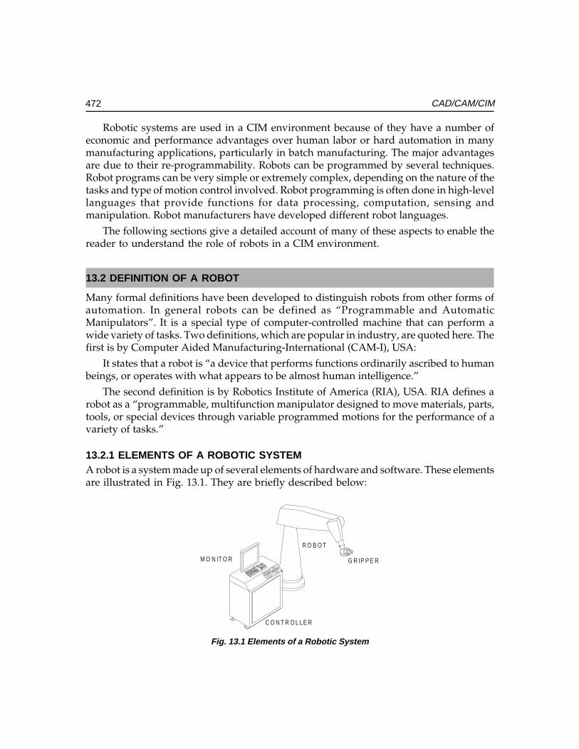
472 CAD/CAM/CIM
Robotic systems are used in a CIM environment because of they have a number ofeconomic and performance advantages over human labor or hard automation in manymanufacturing applications, particularly in batch manufacturing. The major advantagesare due to their re-programmability. Robots can be programmed by several techniques.Robot programs can be very simple or extremely complex, depending on the nature of thetasks and type of motion control involved. Robot programming is often done in high-levellanguages that provide functions for data processing, computation, sensing andmanipulation. Robot manufacturers have developed different robot languages.
The following sections give a detailed account of many of these aspects to enable thereader to understand the role of robots in a CIM environment.
13.2 DEFINITION OF A ROBOT
Many formal definitions have been developed to distinguish robots from other forms ofautomation. In general robots can be defined as “Programmable and AutomaticManipulators”. It is a special type of computer-controlled machine that can perform awide variety of tasks. Two definitions, which are popular in industry, are quoted here. Thefirst is by Computer Aided Manufacturing-International (CAM-I), USA:
It states that a robot is “a device that performs functions ordinarily ascribed to humanbeings, or operates with what appears to be almost human intelligence.”
The second definition is by Robotics Institute of America (RIA), USA. RIA defines arobot as a “programmable, multifunction manipulator designed to move materials, parts,tools, or special devices through variable programmed motions for the performance of avariety of tasks.”
13.2.1 ELEMENTS OF A ROBOTIC SYSTEMA robot is a system made up of several elements of hardware and software. These elementsare illustrated in Fig. 13.1. They are briefly described below:
R O B O T
C O N T R O L LE R
M O N IT O R G R IP P E R
Fig. 13.1 Elements of a Robotic System
Ch
ap
ter
13C
ha
pte
r 13
Ch
ap
ter
13C
ha
pte
r 13
Ch
ap
ter
13
473Robots in Computer Integrated Manufacturing
Mechanical Components:Mechanical Components:Mechanical Components:Mechanical Components:Mechanical Components:They provide the physical robot motions and perform the various tasks. They include:
(i)(i)(i)(i)(i) Components of the robot manipulator:Components of the robot manipulator:Components of the robot manipulator:Components of the robot manipulator:Components of the robot manipulator:(a) A manipulator (the base and arm assembly)(b) End-of-arm tooling, such as a gripper or end effecter(c) Actuators (motors or drives that move the links of the robot) and associated
equipment(d) Transmission elements like belts, pulleys, ball screws, gearing and other
mechanical components.
(ii)(ii)(ii)(ii)(ii) Control system:Control system:Control system:Control system:Control system:The control system is used to generate the necessary signals co-ordinate themovements of the robot. It includes:
(a) Mechanical, hydraulic, pneumatic, electrical, or electronic (either open loopor closed loop) controls.
(b) Sensors including cameras, amplifiers, and related hardware.(c) Equipment interfaces.
(iii)(iii)(iii)(iii)(iii) Computer system:Computer system:Computer system:Computer system:Computer system:This provides the data processing capability necessary to interpolate theintermediate positions and control the movement of the links or arms the robot.It includes:
(a) Microprocessor or a programmable logic controller or a personal computer(b) User interfaces (e.g. keyboard, display, teach pendant)(c) Control software to manipulate the robot for various applications.
Robots can be configured in many different ways by using various combinations of theabove elements. Since robots are designed to perform tasks that might otherwise requirehumans, many of their basic features are like those of a human arm. For example, anarticulated robot has arm, hand, wrist and gripper to reach, grasp and manipulate objects.They are driven by a power source, which provides the energy necessary for theirmovements. They can be programmed or can have an intelligent control system, controlledby neural, fuzzy or fuzzy neural techniques, which can acquire, store, process and performon the basis of the data collected by sensors attached to the robot.
13.2.2 NEED FOR USING ROBOTSRobots are being used increasingly in manufacturing applications for many reasons. In manysituations, they have a number of advantages over employing humans or special purpose,hard or fixed automation. The important benefits from the use of robots are listed below:
(i) Robots can be built with performance capabilities superior to those of humanbeings in terms of strength, size, speed, accuracy and repeatability.
474 CAD/CAM/CIM
(ii) Robots are better than humans to perform simple and repetitive tasks withbetter quality and consistency.
(iii) Robots can replace humans in performing tasks that are difficult and hazardousbecause of factors such as size, weight, reach, precision or environment (e.g., heat(as in pressure die casting), dust (as in foundries), chemicals (detection of mines),nuclear radiation, and pollution).
(iv) Robots do not have the limitations and negative attributes of human workers,such as fatigue, need for rest, diversion of attention, absenteeism, need forrefreshments etc.
(v) Robots can be used to perform tasks which human operators do not like to do- jobs that are considered unskilled, demeaning, or low-paying or that involvepoor working conditions.
(vi) Robots can lower costs, through reduction in usage of materials, through theirefficiency and consistency.
(vii) Robots become more economical as labor costs increase.(viii) Robots are flexible compared to hard automation since they can be reconfigured
and reprogrammed. This permits them to be reused in new or modifiedapplications, and they are less likely to become obsolete. The output of thehumans will depend upon the learning curve every time the job is changed.
Thus robots can do jobs easier and faster to implement automation since they are moreflexible. The flexibility is due to their reprogrammability. One can expect generally lessdown time with robots than complex hard automation in batch manufacturing operations.
Although robots may have all these advantages, they are not always the best choice forall manufacturing applications. Even though they may have a wide range of capabilities,they still cannot match the unique combination of mental skill and alertness and physicaldexterity of a human operator. Robots, however, can supplement human operators toenhance their productivity.
13.3 TYPES OF ROBOTS
Industrial robots are designed in a variety of shapes and sizes. They can be classifiedbased on a few basic characteristic features. These are listed below:
(i) The physical geometry of the manipulator arm and base unit and their degreesof freedom (DOF) (Movements along different axes).
(ii) The complexity of the path in which the manipulator can move. (Point to pointin the case of a pick and place robot, continuous in the case of a welding robot).
(iii) The type of power source used to move the manipulator. (Electrical, hydraulic,pneumatic etc.).
(iv) The techniques and systems used to control the motion of the manipulator. (Servoand non-servo).
(v) Depending on whether the robot is stationary or mobile.
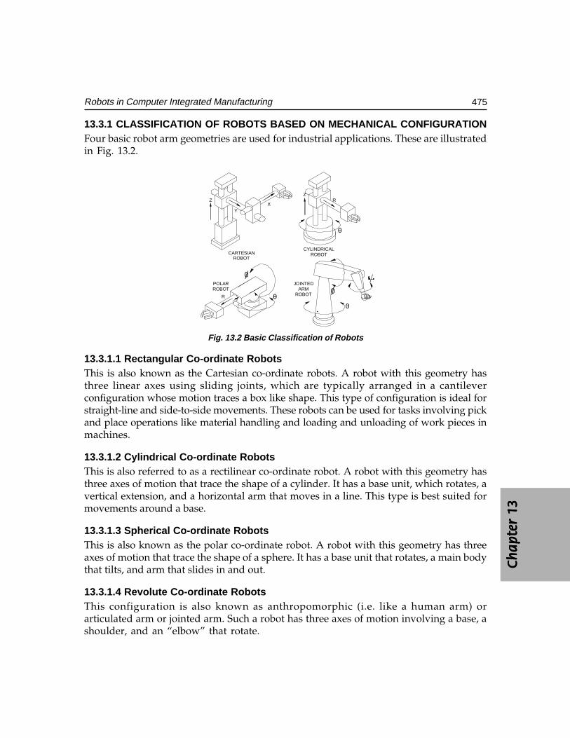
Ch
ap
ter
13C
ha
pte
r 13
Ch
ap
ter
13C
ha
pte
r 13
Ch
ap
ter
13
475Robots in Computer Integrated Manufacturing
13.3.1 CLASSIFICATION OF ROBOTS BASED ON MECHANICAL CONFIGURATIONFour basic robot arm geometries are used for industrial applications. These are illustratedin Fig. 13.2.
CARTESIANROBOT
CYLINDRICALROBOT
POLARROBOT
JOINTEDARM
ROBOT
Z
YX
ZR
R
0
00
0
0
Fig. 13.2 Basic Classification of Robots
13.3.1.1 Rectangular Co-ordinate RobotsThis is also known as the Cartesian co-ordinate robots. A robot with this geometry hasthree linear axes using sliding joints, which are typically arranged in a cantileverconfiguration whose motion traces a box like shape. This type of configuration is ideal forstraight-line and side-to-side movements. These robots can be used for tasks involving pickand place operations like material handling and loading and unloading of work pieces inmachines.
13.3.1.2 Cylindrical Co-ordinate RobotsThis is also referred to as a rectilinear co-ordinate robot. A robot with this geometry hasthree axes of motion that trace the shape of a cylinder. It has a base unit, which rotates, avertical extension, and a horizontal arm that moves in a line. This type is best suited formovements around a base.
13.3.1.3 Spherical Co-ordinate RobotsThis is also known as the polar co-ordinate robot. A robot with this geometry has threeaxes of motion that trace the shape of a sphere. It has a base unit that rotates, a main bodythat tilts, and arm that slides in and out.
13.3.1.4 Revolute Co-ordinate RobotsThis configuration is also known as anthropomorphic (i.e. like a human arm) orarticulated arm or jointed arm. Such a robot has three axes of motion involving a base, ashoulder, and an “elbow” that rotate.
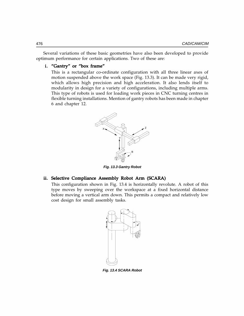
476 CAD/CAM/CIM
Several variations of these basic geometries have also been developed to provideoptimum performance for certain applications. Two of these are:
i.i.i.i.i. “Gantry” or “box frame”“Gantry” or “box frame”“Gantry” or “box frame”“Gantry” or “box frame”“Gantry” or “box frame”This is a rectangular co-ordinate configuration with all three linear axes ofmotion suspended above the work space (Fig. 13.3). It can be made very rigid,which allows high precision and high acceleration. It also lends itself tomodularity in design for a variety of configurations, including multiple arms.This type of robots is used for loading work pieces in CNC turning centres inflexible turning installations. Mention of gantry robots has been made in chapter6 and chapter 12.
X
Y
Z
B
Fig. 13.3 Gantry Robot
ii.ii.ii.ii.ii. Selective Compliance Assembly Robot Arm (SCARA)Selective Compliance Assembly Robot Arm (SCARA)Selective Compliance Assembly Robot Arm (SCARA)Selective Compliance Assembly Robot Arm (SCARA)Selective Compliance Assembly Robot Arm (SCARA)This configuration shown in Fig. 13.4 is horizontally revolute. A robot of thistype moves by sweeping over the workspace at a fixed horizontal distancebefore moving a vertical arm down. This permits a compact and relatively lowcost design for small assembly tasks.
Fig. 13.4 SCARA Robot
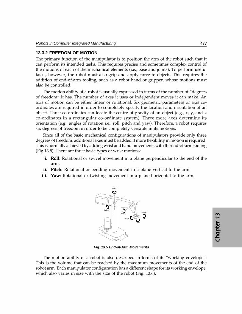
Ch
ap
ter
13C
ha
pte
r 13
Ch
ap
ter
13C
ha
pte
r 13
Ch
ap
ter
13
477Robots in Computer Integrated Manufacturing
13.3.2 FREEDOM OF MOTIONThe primary function of the manipulator is to position the arm of the robot such that itcan perform its intended tasks. This requires precise and sometimes complex control ofthe motions of each of the mechanical elements (i.e., base and joints). To perform usefultasks, however, the robot must also grip and apply force to objects. This requires theaddition of end-of-arm tooling, such as a robot hand or gripper, whose motions mustalso be controlled.
The motion ability of a robot is usually expressed in terms of the number of “degreesof freedom” it has. The number of axes it uses or independent moves it can make. Anaxis of motion can be either linear or rotational. Six geometric parameters or axis co-ordinates are required in order to completely specify the location and orientation of anobject. Three co-ordinates can locate the centre of gravity of an object (e.g., x, y, and zco-ordinates in a rectangular co-ordinate system). Three more axes determine itsorientation (e.g., angles of rotation i.e., roll, pitch and yaw). Therefore, a robot requiressix degrees of freedom in order to be completely versatile in its motions.
Since all of the basic mechanical configurations of manipulators provide only threedegrees of freedom, additional axes must be added if more flexibility in motion is required.This is normally achieved by adding wrist and hand movements with the end-of-arm tooling(Fig 13.5). There are three basic types of wrist motions:
i.i.i.i.i. Roll: Roll: Roll: Roll: Roll: Rotational or swivel movement in a plane perpendicular to the end of thearm.
ii.ii.ii.ii.ii. Pitch: Pitch: Pitch: Pitch: Pitch: Rotational or bending movement in a plane vertical to the arm.iii.iii.iii.iii.iii. YawYawYawYawYaw: Rotational or twisting movement in a plane horizontal to the arm.
Axis 1
Axis 2
Axis 3 Pitch
Roll
Yaw
Fig. 13.5 End-of-Arm Movements
The motion ability of a robot is also described in terms of its “working envelope”.This is the volume that can be reached by the maximum movements of the end of therobot arm. Each manipulator configuration has a different shape for its working envelope,which also varies in size with the size of the robot (Fig. 13.6).
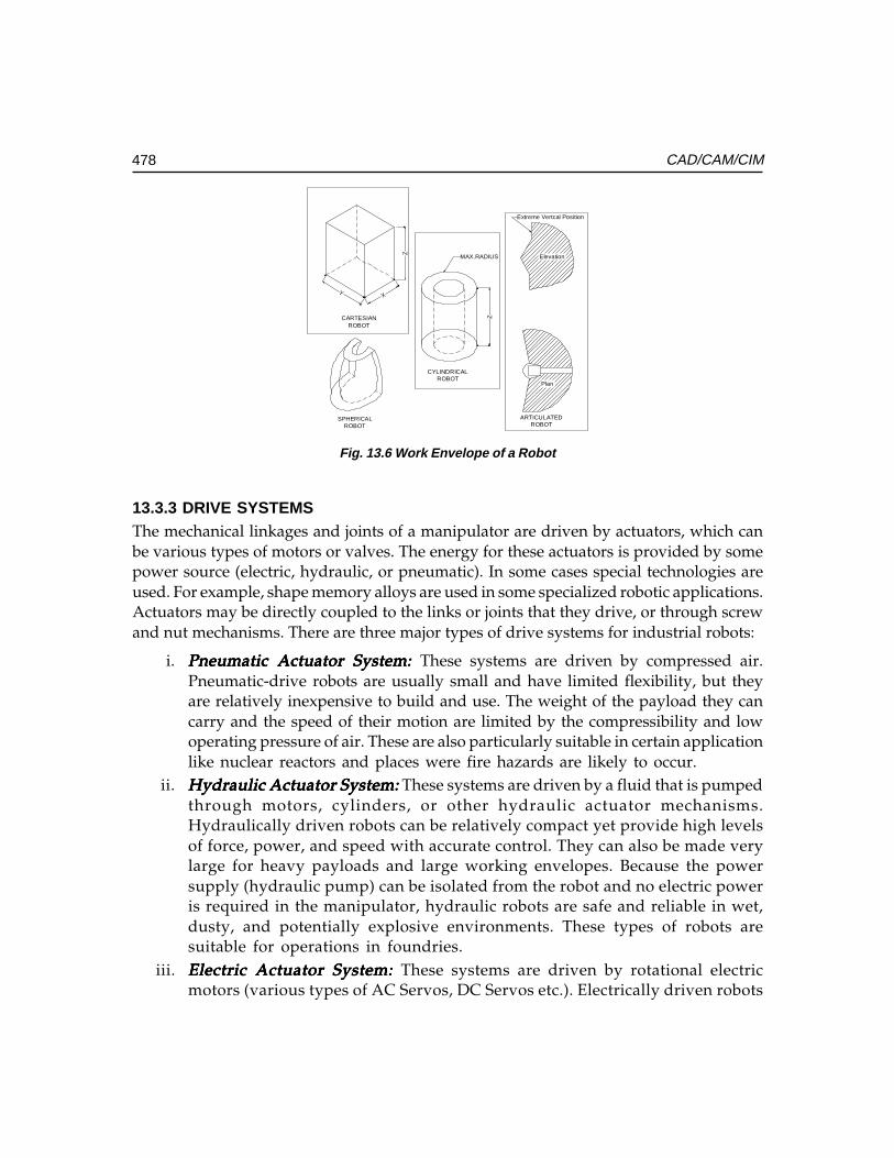
478 CAD/CAM/CIM
XY
Z
MAX.RADIUS
ZCARTESIANROBOT
CYLINDRICALROBOT
SPHERICALROBOT
ARTICULATEDROBOT
Elevation
Plan
Extreme Vertcal Position
Fig. 13.6 Work Envelope of a Robot
13.3.3 DRIVE SYSTEMSThe mechanical linkages and joints of a manipulator are driven by actuators, which canbe various types of motors or valves. The energy for these actuators is provided by somepower source (electric, hydraulic, or pneumatic). In some cases special technologies areused. For example, shape memory alloys are used in some specialized robotic applications.Actuators may be directly coupled to the links or joints that they drive, or through screwand nut mechanisms. There are three major types of drive systems for industrial robots:
i. Pneumatic Actuator System:Pneumatic Actuator System:Pneumatic Actuator System:Pneumatic Actuator System:Pneumatic Actuator System: These systems are driven by compressed air.Pneumatic-drive robots are usually small and have limited flexibility, but theyare relatively inexpensive to build and use. The weight of the payload they cancarry and the speed of their motion are limited by the compressibility and lowoperating pressure of air. These are also particularly suitable in certain applicationlike nuclear reactors and places were fire hazards are likely to occur.
ii. Hydraulic Actuator System:Hydraulic Actuator System:Hydraulic Actuator System:Hydraulic Actuator System:Hydraulic Actuator System: These systems are driven by a fluid that is pumpedthrough motors, cylinders, or other hydraulic actuator mechanisms.Hydraulically driven robots can be relatively compact yet provide high levelsof force, power, and speed with accurate control. They can also be made verylarge for heavy payloads and large working envelopes. Because the powersupply (hydraulic pump) can be isolated from the robot and no electric poweris required in the manipulator, hydraulic robots are safe and reliable in wet,dusty, and potentially explosive environments. These types of robots aresuitable for operations in foundries.
iii. Electric Actuator System:Electric Actuator System:Electric Actuator System:Electric Actuator System:Electric Actuator System: These systems are driven by rotational electricmotors (various types of AC Servos, DC Servos etc.). Electrically driven robots
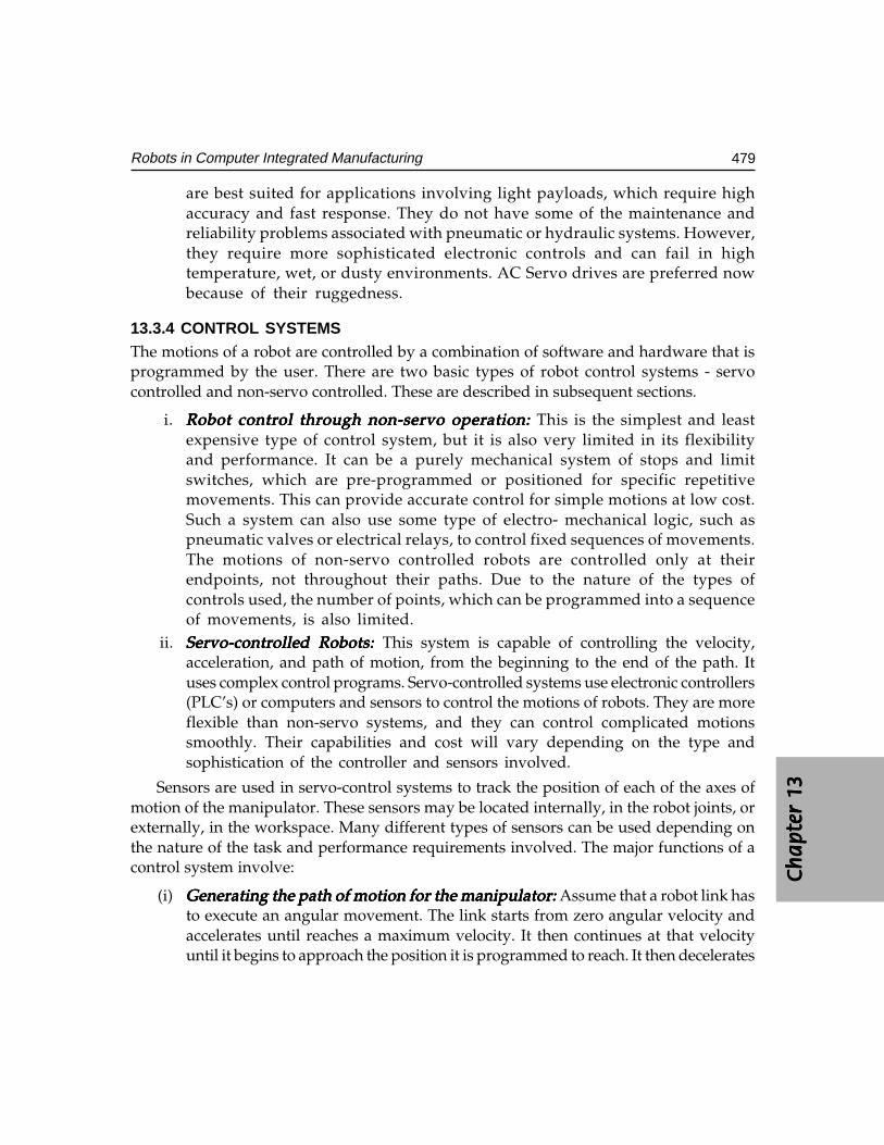
Ch
ap
ter
13C
ha
pte
r 13
Ch
ap
ter
13C
ha
pte
r 13
Ch
ap
ter
13
479Robots in Computer Integrated Manufacturing
are best suited for applications involving light payloads, which require highaccuracy and fast response. They do not have some of the maintenance andreliability problems associated with pneumatic or hydraulic systems. However,they require more sophisticated electronic controls and can fail in hightemperature, wet, or dusty environments. AC Servo drives are preferred nowbecause of their ruggedness.
13.3.4 CONTROL SYSTEMSThe motions of a robot are controlled by a combination of software and hardware that isprogrammed by the user. There are two basic types of robot control systems - servocontrolled and non-servo controlled. These are described in subsequent sections.
i. Robot control through non-servo operation:Robot control through non-servo operation:Robot control through non-servo operation:Robot control through non-servo operation:Robot control through non-servo operation: This is the simplest and leastexpensive type of control system, but it is also very limited in its flexibilityand performance. It can be a purely mechanical system of stops and limitswitches, which are pre-programmed or positioned for specific repetitivemovements. This can provide accurate control for simple motions at low cost.Such a system can also use some type of electro- mechanical logic, such aspneumatic valves or electrical relays, to control fixed sequences of movements.The motions of non-servo controlled robots are controlled only at theirendpoints, not throughout their paths. Due to the nature of the types ofcontrols used, the number of points, which can be programmed into a sequenceof movements, is also limited.
ii. Servo-controlled Robots: Servo-controlled Robots: Servo-controlled Robots: Servo-controlled Robots: Servo-controlled Robots: This system is capable of controlling the velocity,acceleration, and path of motion, from the beginning to the end of the path. Ituses complex control programs. Servo-controlled systems use electronic controllers(PLC’s) or computers and sensors to control the motions of robots. They are moreflexible than non-servo systems, and they can control complicated motionssmoothly. Their capabilities and cost will vary depending on the type andsophistication of the controller and sensors involved.
Sensors are used in servo-control systems to track the position of each of the axes ofmotion of the manipulator. These sensors may be located internally, in the robot joints, orexternally, in the workspace. Many different types of sensors can be used depending onthe nature of the task and performance requirements involved. The major functions of acontrol system involve:
(i) Generating the path of motion for the manipulator:Generating the path of motion for the manipulator:Generating the path of motion for the manipulator:Generating the path of motion for the manipulator:Generating the path of motion for the manipulator: Assume that a robot link hasto execute an angular movement. The link starts from zero angular velocity andaccelerates until reaches a maximum velocity. It then continues at that velocityuntil it begins to approach the position it is programmed to reach. It then decelerates
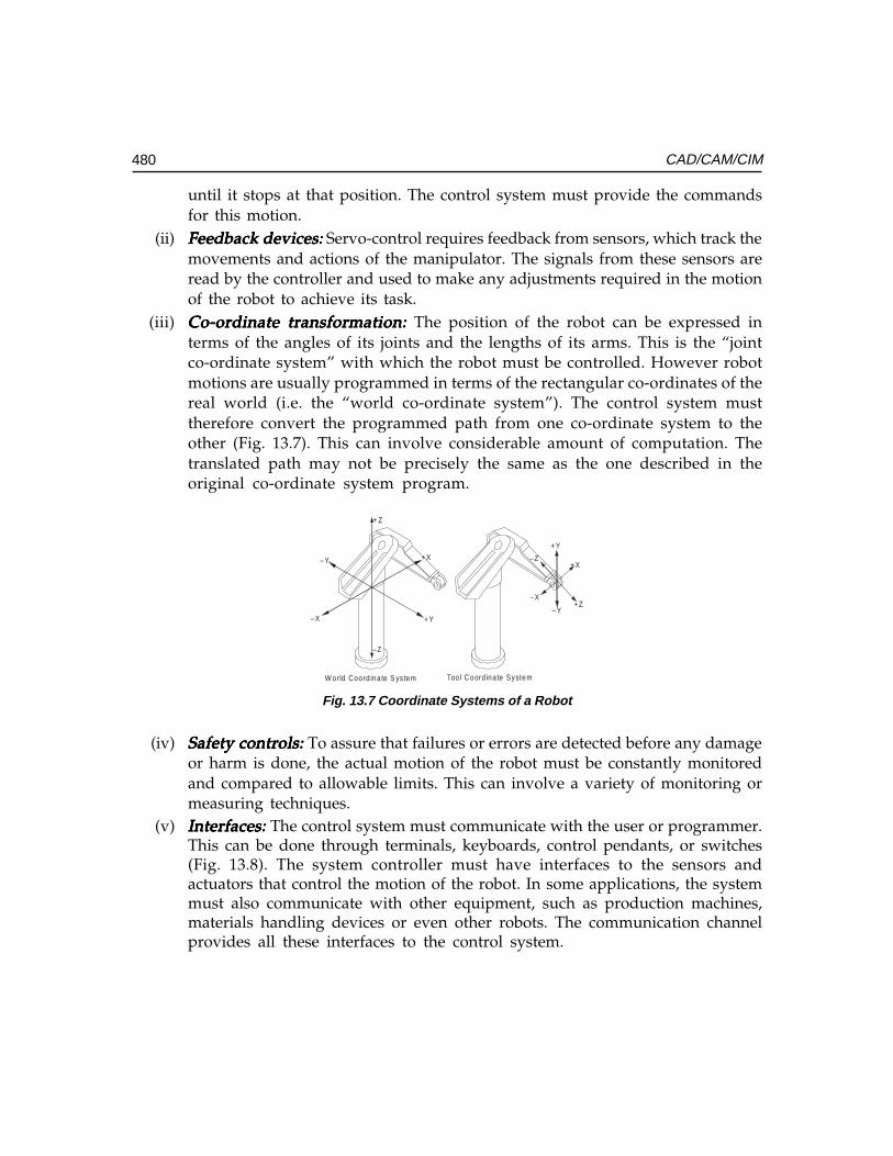
480 CAD/CAM/CIM
until it stops at that position. The control system must provide the commandsfor this motion.
(ii) Feedback devices:Feedback devices:Feedback devices:Feedback devices:Feedback devices: Servo-control requires feedback from sensors, which track themovements and actions of the manipulator. The signals from these sensors areread by the controller and used to make any adjustments required in the motionof the robot to achieve its task.
(iii) Co-ordinate transformation: Co-ordinate transformation: Co-ordinate transformation: Co-ordinate transformation: Co-ordinate transformation: The position of the robot can be expressed interms of the angles of its joints and the lengths of its arms. This is the “jointco-ordinate system” with which the robot must be controlled. However robotmotions are usually programmed in terms of the rectangular co-ordinates of thereal world (i.e. the “world co-ordinate system”). The control system musttherefore convert the programmed path from one co-ordinate system to theother (Fig. 13.7). This can involve considerable amount of computation. Thetranslated path may not be precisely the same as the one described in theoriginal co-ordinate system program.
+ Z
–Z
+ X
–X
–Y
+ Y
+ Z
–Z+ X
–X
+ Y
–Y
W orld Coord ina te S ys tem Too l C oord ina te System
Fig. 13.7 Coordinate Systems of a Robot
(iv) Safety controls: Safety controls: Safety controls: Safety controls: Safety controls: To assure that failures or errors are detected before any damageor harm is done, the actual motion of the robot must be constantly monitoredand compared to allowable limits. This can involve a variety of monitoring ormeasuring techniques.
(v) Interfaces: Interfaces: Interfaces: Interfaces: Interfaces: The control system must communicate with the user or programmer.This can be done through terminals, keyboards, control pendants, or switches(Fig. 13.8). The system controller must have interfaces to the sensors andactuators that control the motion of the robot. In some applications, the systemmust also communicate with other equipment, such as production machines,materials handling devices or even other robots. The communication channelprovides all these interfaces to the control system.
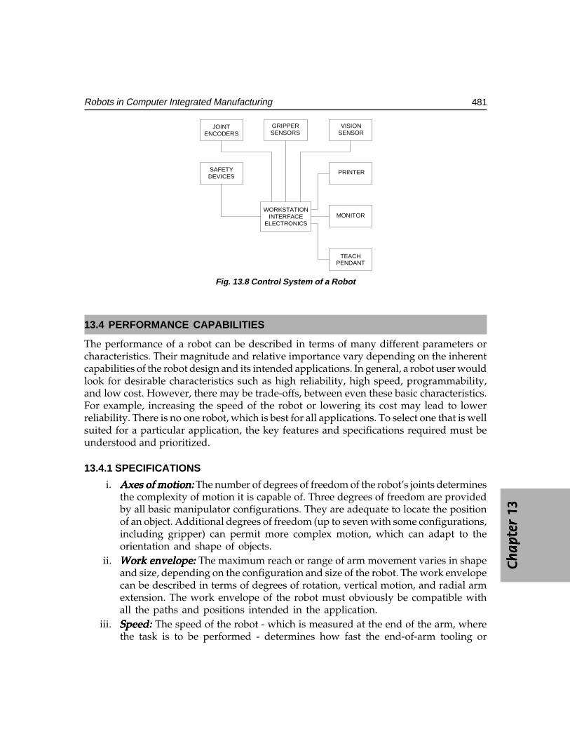
Ch
ap
ter
13C
ha
pte
r 13
Ch
ap
ter
13C
ha
pte
r 13
Ch
ap
ter
13
481Robots in Computer Integrated Manufacturing
JOINTENCODERS
GRIPPERSENSORS
VISIONSENSOR
SAFETYDEVICES
PRINTER
MONITOR
TEACHPENDANT
WORKSTATIONINTERFACE
ELECTRONICS
Fig. 13.8 Control System of a Robot
13.4 PERFORMANCE CAPABILITIES
The performance of a robot can be described in terms of many different parameters orcharacteristics. Their magnitude and relative importance vary depending on the inherentcapabilities of the robot design and its intended applications. In general, a robot user wouldlook for desirable characteristics such as high reliability, high speed, programmability,and low cost. However, there may be trade-offs, between even these basic characteristics.For example, increasing the speed of the robot or lowering its cost may lead to lowerreliability. There is no one robot, which is best for all applications. To select one that is wellsuited for a particular application, the key features and specifications required must beunderstood and prioritized.
13.4.1 SPECIFICATIONS
i. Axes of motion:Axes of motion:Axes of motion:Axes of motion:Axes of motion: The number of degrees of freedom of the robot’s joints determinesthe complexity of motion it is capable of. Three degrees of freedom are providedby all basic manipulator configurations. They are adequate to locate the positionof an object. Additional degrees of freedom (up to seven with some configurations,including gripper) can permit more complex motion, which can adapt to theorientation and shape of objects.
ii. Work envelope: Work envelope: Work envelope: Work envelope: Work envelope: The maximum reach or range of arm movement varies in shapeand size, depending on the configuration and size of the robot. The work envelopecan be described in terms of degrees of rotation, vertical motion, and radial armextension. The work envelope of the robot must obviously be compatible withall the paths and positions intended in the application.
iii. Speed:Speed:Speed:Speed:Speed: The speed of the robot - which is measured at the end of the arm, wherethe task is to be performed - determines how fast the end-of-arm tooling or
482 CAD/CAM/CIM
gripper can get from one position to another. This speed will vary, dependingon payload, position in the work envelope, and axis of movement.
(iv) Acceleration:Acceleration:Acceleration:Acceleration:Acceleration: This is the rate at which the robot can reach its programmedspeed. It can be important for complex paths, in which the time to reachmaximum velocity can be a significant portion of the total travel time. Theacceleration capability of a robot is determined by the power is built into thedrive system. Hydraulic drives can provide very high accelerations by storingenergy in an accumulator.
(v) Payload capacity:Payload capacity:Payload capacity:Payload capacity:Payload capacity: The maximum weight the robot can carry is normally specifiedat low or normal speeds. It depends on the size and configuration of the robot.High payload capacity is a compromise with some other performancespecifications, such as maximum speed, acceleration and accuracy. Very largerobots can even carry payloads of several hundred kilograms.
(vi) Accuracy: Accuracy: Accuracy: Accuracy: Accuracy: The Accuracy denotes how closely the end of the robot arm can bemoved to a specific position. This is a function of several factors:(a) The basic geometric configuration of the manipulator.(b) The mathematical function used by the control system to convert position
specifications from world co-ordinates to joint co-ordinates.(c) The effects of the payload on deflections and distortions in the joints and
arms, because of the robot’s static and dynamic compliances.(d) The effects of temperature on the joints and arms.(e) Errors in the control system.(f) The accuracy of the specification of the end position or objects to be reached.(g) Degradation or drift in the performance of the actuators and sensors.
(vii) Resolution:Resolution:Resolution:Resolution:Resolution: This may also be referred to as the precision of the robot. Resolutionis the smallest increment of motion for which the robot can be controlled; it isnormally dependent on the sensors used.
(viii) Repeatability: Repeatability: Repeatability: Repeatability: Repeatability: Repeatability is the ability of the manipulator to repeatedly returnto exactly the same position. It depends on the stability of the control system andis affected by temperature, load and joint clearances.
(ix) Reliability:Reliability:Reliability:Reliability:Reliability: This is measured in terms of the average time between failures.Reliability depends on the speed and load during operation as well as on thequality of the robot design and control system. Industrial robots have usuallyhigh values of mean time between failures (MTBF).
13.4.2 KEY FEATURE CAPABILITIESIn addition to the typical specifications, which define a robot’s performance capabilities, anumber of other features can also influence its performance. These features are moresubjective and therefore difficult to quantify. They are:
Ch
ap
ter
13C
ha
pte
r 13
Ch
ap
ter
13C
ha
pte
r 13
Ch
ap
ter
13
483Robots in Computer Integrated Manufacturing
i. Quality: Quality: Quality: Quality: Quality: Generally, one can expect higher accuracy and reliability from robotsthat are built with better and more rugged electrical and mechanical components.
ii. Serviceability: Serviceability: Serviceability: Serviceability: Serviceability: Many features can be added to the design of the robot tominimize both the frequency of failure and time it takes for repair. Such featuresinclude conservative designs for electrical and mechanical parts, modular designand extensive use of standard parts.
iii. Safety: Safety: Safety: Safety: Safety: A wide variety of features are incorporated to prevent damage or injuryduring robot operation, including sensors, limit switches and end stops. Thedesign of the work cell is as important as the selection of the robot.
iv. Modularity: Modularity: Modularity: Modularity: Modularity: Adoption modular design technique enables for the manipulator tobe reconfigured for different applications.
v. Dexterity:Dexterity:Dexterity:Dexterity:Dexterity: This is the ability of the manipulator to perform delicate, precise, orcomplex tasks. This depends on the number of axes and the design of the gripper.
13.4.3 TECHNICAL SPECIFICATION OF A ROBOT
Typical specifications of a robot are given below:Typical specifications of a robot are given below:Typical specifications of a robot are given below:Typical specifications of a robot are given below:Typical specifications of a robot are given below:No. of axes 6Maximum reach 1 mPayload 8 kgfRepeatability + 0.025 mmJoint speed 90 deg/secWaist rotation 290 degShoulder rotation 300 degElbow rotation 300 degWrist pitch + 90 degWrist roll + 180 degDrive AC ServomotorMounting options Pedestal, table top, floor, overhead, servo track
Controller specifications:Controller specifications:Controller specifications:Controller specifications:Controller specifications:Processor 32 bitMemory 10 MBCommunication RS 232 Serial portsUser I/O 32 digital I/O24 analog I/OProgramming Language AR-SMART, AR-BASIC
484 CAD/CAM/CIM
13.5 PROGRAMMING ROBOTS
The major advantage that robots have over fixed automation is their ability to bereprogrammed. They can perform complex tasks under the control of stored programs,which can be modified at will. In addition they can move in response to real time inputsfrom sensors. Programming is an important feature of robots, and it is also a significantcomponent in their design and application. The process of robot programming involves“teaching” it the task to be performed, storing the program, executing the program, anddebugging it. A number of different techniques and software approaches are used toprogram robots.
The kinematic analysis of a robot means the determination of position, velocity andacceleration of the various links of the robot. This can be of two types - direct kinematicsand inverse kinematics. Direct kinematics involves determination of position of the endeffectors for specified displacement of links. Inverse kinematics deals with the problemof the calculation of link movements to achieve a desired position of the end effectors.The inverse kinematics problem is important in most of robotic applications. Theprogramming of the robot involves the coding of the data obtained from direct/inversekinematic analysis so that the end effector of the robot is positioned suitably for therequired applications.
The principal task of the robot program is to control the motions and actions of themanipulator. However, due to the inaccuracies and uncertainties involved in the positionsand movements of robots, much of the programming involved deals with the detectionand correction of errors. Programs must also be written to deal with both user and machines.The user may include professional programmers, as well as operators, maintenancepersonnel, and application engineers.
13.5.1 PROGRAMMING METHODSThe following methods are commonly used to program robots:
i. Guiding: Guiding: Guiding: Guiding: Guiding: This is also known as the “Walk through” or “Playback” method. Itinvolves manipulating the robot arm so that it can be moved manually throughthe intended motions while its link movements are being recorded by the controlsystem. This is the simplest technique and does not require the operator to writeany program code, but it is limited to relatively short and simple motions. Withthis method, the operator physically guides the robot through its movements. Thestored “program” of robot motion can then be played back, during the actualperformance of the task. It is also possible to edit this program to optimize it.
ii. Teach pendant:Teach pendant:Teach pendant:Teach pendant:Teach pendant: This is also known as the “lead through” method. It uses a controlpanel, called a “teach pendant”, which has buttons or switches that control themotion of the robot. The operator or programmer can lead the manipulatorthrough the task one step at a time, recording each incremental move along theway. Only the major points in the path of the robot’s movements are recorded,
Ch
ap
ter
13C
ha
pte
r 13
Ch
ap
ter
13C
ha
pte
r 13
Ch
ap
ter
13
485Robots in Computer Integrated Manufacturing
so the intermediate points must be interpolated or calculated by the controlsystem. The control system then generates a program for the complete path ofthe robot. Like the walk through method, this technique does not require codewriting, but it can be used for more complex and precise tasks. It is often usedfor developing applications or training.
iii. Off-line programming:Off-line programming:Off-line programming:Off-line programming:Off-line programming: This is the most common method of robot programmingin which a high-level language is used to write a control program. This programdescribes all the movements and actions of each of the links of the robot. Theprogram may involve many steps, requiring a large number of lines of programcode. In addition, a great deal of computation is normally associated with thetranslation and generation of path of motion. This method of control is the mostflexible and can also enable the robot to respond to signals from external sensorsto modify its movements.
iv. On-line programming: On-line programming: On-line programming: On-line programming: On-line programming: A variation of the above programming method is on-line programming. This requires the availability of a robot, but it also gives theprogrammer the ability to see the motions of the robot actually executing theprogram as it is being developed. In most cases, this approach is used eitheras a substitute for a teach pendant or to debug programs that have been writtenoff-line.
v. Comparison of off-line and on-line programming:Comparison of off-line and on-line programming:Comparison of off-line and on-line programming:Comparison of off-line and on-line programming:Comparison of off-line and on-line programming: On-line and off-lineprogramming are used on different control levels of the robot cell. Off-lineprogramming supports the integration of robots into a CIM system. It allows themanipulation of CAD system data to reduce the programming time by eliminatingthe interaction with the physical devices. The programming method, however,has difficulty in handling sensor information, and this obliges the programmerto use simulation, which allows modeling of the sensor input in critical situationsand its interpretation. In general, an off-line programming system needs a softwaredevelopment environment to specify the application requirements, to analyze thetasks, and to decompose the global task to subtasks. Program test facilities areneeded, as well. An on-line programming system provides tools for debuggingand testing the program. Here the use of the physical robot system is required.An on-line language is more convenient to non-expert users.
13.5.2 ROBOT PROGRAMMING FUNCTIONSA robot programming system involves major functions to make the execution of the actualtask possible.
(i) Modeling the work space:Modeling the work space:Modeling the work space:Modeling the work space:Modeling the work space: A significant part of specifying the robot’s task isdefining the positions of the elements and constraints involved in the application.When the task environment is not known precisely, the position of the robot mustbe specified relative to the objects. Position data may be obtained from severalsources, such as robot sensors, geometric models, or external sensing systems.
486 CAD/CAM/CIM
(ii) Path generation:Path generation:Path generation:Path generation:Path generation: The path of motion is normally specified by interpolatingintermediate points from a sequence of motions and positions identified in theprogram. As mentioned earlier, the position specifications must be translatedfrom world co-ordinates to joint co-ordinates, which the robot control system canunderstand. The type of path generated may not be coordinated between thejoints. That is, each joint may move independent of the others. This will normallyresult in a non-uniform, curved path. If straight line motion is desired, themotions of the joints must be coordinated.
(iii) Sensing:Sensing:Sensing:Sensing:Sensing: The use of sensors permits the robot to deal with uncertainties, whichmay include:(a) The detection of errors.(b) The identification of objects or positions, using a vision system.(c) The initiation or termination of actions, using limit switches, proximity
switches or feedback devices.To use sensors, the robot control system must be able to connect and interpret sensory
data from internal or external sources and generate control signals that will modify theactions of the manipulator. The data acquisition, computation, and output signal generationactivities must be built into the control program. A sensor-based robot must have a programthat allows it to choose between alternative actions on the basis of data from the sensorsand its model of the environment.
(iv) Programming support:Programming support:Programming support:Programming support:Programming support: Some of other functions that are necessary in aprogramming system for robots include:(a) Editing tools for modifying programs.(b) Debugging tools for finding problems during program development.(c) Diagnostic tools for finding problems during operation.(d) Simulators for trying out robot programs without actually operating the robot.(e) Interfaces to controllers, peripheral equipment, and other computers.
13.5.3 THE ROBOT PROGRAMMING ENVIRONMENTToday, robots are mainly used in high volume or medium lot production. Examples arespot welding of automotive chassis and component insertion in printed circuit boards.With the classical on-line programming methods a robot cannot be used for productionduring the programming. For this reason, off-line programming systems are needed as alinkage to production planning. Thus a higher flexibility and short manufacturing planningcycles can be realized.
On-line programming languages for robots should support:
(i) The specification of the program flow control.(ii) The capability of writing subroutines for exception handling.
(iii) The sensor interaction and the rules for the sensor-guided path control.
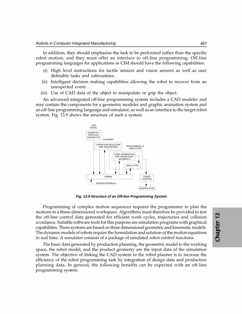
Ch
ap
ter
13C
ha
pte
r 13
Ch
ap
ter
13C
ha
pte
r 13
Ch
ap
ter
13
487Robots in Computer Integrated Manufacturing
In addition, they should emphasize the task to be performed rather than the specificrobot motion, and they must offer an interface to off-line programming. Off-lineprogramming languages for applications in CIM should have the following capabilities:
(i) High level instructions for tactile sensors and vision sensors as well as userdefinable tasks and subroutines.
(ii) Intelligent decision making capabilities allowing the robot to recover from anunexpected event.
(iii) Use of CAD data of the object to manipulate or grip the object.An advanced integrated off-line programming system includes a CAD modeler and
may contain the components for a geometric modeler and graphic animation system andan off-line programming language and simulator, as well as an interface to the target robotsystem. Fig. 13.9 shows the structure of such a system.
GEOMETRYTOPOLOGYKINEMATICS
OPERATION SELECTIONAND SEQUENCING
CODE GENERATIONFOR TRAJECTORY
SEGMENTS
SIMULATION
CADMODEL
PLANNING
RDBMS ROBOTCONTROL
MANIPULATOR
SENSOR FEEDBACK
PROGRAMMING &SIMULATION
Fig. 13.9 Structure of an Off-line Programming System
Programming of complex motion sequences requires the programmer to plan themotions in a three-dimensional workspace. Algorithms must therefore be provided to testthe off-line control data generated for efficient work cycles, trajectories and collisionavoidance. Suitable software tools for this purpose are simulation programs with graphicalcapabilities. These systems are based on three dimensional geometric and kinematic models.The dynamic models of robots require the formulation and solution of the motion equationsin real time. A simulator consists of a package of emulated robot control functions.
The basic data generated by production planning, the geometric model to the workingspace, the robot model, and the product geometry are the input data of the simulationsystem. The objective of linking the CAD system to the robot planner is to increase theefficiency of the robot programming task by integration of design data and productionplanning data. In general, the following benefits can be expected with an off-lineprogramming system:
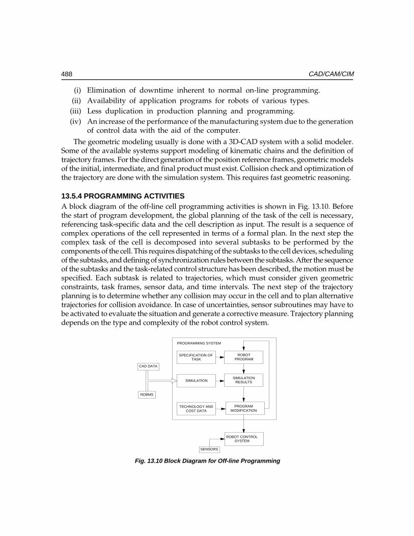
488 CAD/CAM/CIM
(i) Elimination of downtime inherent to normal on-line programming.(ii) Availability of application programs for robots of various types.
(iii) Less duplication in production planning and programming.(iv) An increase of the performance of the manufacturing system due to the generation
of control data with the aid of the computer.
The geometric modeling usually is done with a 3D-CAD system with a solid modeler.Some of the available systems support modeling of kinematic chains and the definition oftrajectory frames. For the direct generation of the position reference frames, geometric modelsof the initial, intermediate, and final product must exist. Collision check and optimization ofthe trajectory are done with the simulation system. This requires fast geometric reasoning.
13.5.4 PROGRAMMING ACTIVITIESA block diagram of the off-line cell programming activities is shown in Fig. 13.10. Beforethe start of program development, the global planning of the task of the cell is necessary,referencing task-specific data and the cell description as input. The result is a sequence ofcomplex operations of the cell represented in terms of a formal plan. In the next step thecomplex task of the cell is decomposed into several subtasks to be performed by thecomponents of the cell. This requires dispatching of the subtasks to the cell devices, schedulingof the subtasks, and defining of synchronization rules between the subtasks. After the sequenceof the subtasks and the task-related control structure has been described, the motion must bespecified. Each subtask is related to trajectories, which must consider given geometricconstraints, task frames, sensor data, and time intervals. The next step of the trajectoryplanning is to determine whether any collision may occur in the cell and to plan alternativetrajectories for collision avoidance. In case of uncertainties, sensor subroutines may have tobe activated to evaluate the situation and generate a corrective measure. Trajectory planningdepends on the type and complexity of the robot control system.
SPECIFICATION OF TASK
ROBOTPROGRAM
SIMULATIONSIMULATION
RESULTS
TECHNOLOGY ANDCOST DATA
PROGRAMMODIFICATION
ROBOT CONTROLSYSTEM
CAD DATA
RDBMS
SENSORS
PROGRAMMING SYSTEM
Fig. 13.10 Block Diagram for Off-line Programming
Ch
ap
ter
13C
ha
pte
r 13
Ch
ap
ter
13C
ha
pte
r 13
Ch
ap
ter
13
489Robots in Computer Integrated Manufacturing
13.5.5 PROGRAMMING LANGUAGE OF INDUSTRIAL ROBOTSPresently, there are more than 300 robot programming languages. Programminglanguages can be classified as explicit or implicit. Explicit programming languages arebased on such classical programming languages as Pascal, C, Modula-2, and Assembler.Object oriented languages like Small Talk or C++ are also applied in programming systems.An implicit robot programming system is based on a world model and knowledge aboutthe task to be performed. A world model can be implemented with the help of the frameconcept that originates from artificial intelligence. A frame is a logic structure suitable ofprocessing facts and world data; it can be represented with the help of a relationaldatabase to obtain direct access to the stored information about the robot world. Relationaldatabase is an essential part of an implicit robot programming system. Two types ofinformation are used to describe the world. One contains geometric and the other non-geometric parameters. The programmer must access both types and combine the retrievedinformation for the application at hand.
Relation between objects and attributes of the objects are parameters needed forimplicit robot programming. Other data required are sensor parameters, descriptions ofthe robot (geometric, kinematic, and dynamic) and control data (trajectories).
13.5.6 BASIC TYPES OF ROBOT PROGRAMMING LANGUAGESThe robot programming languages can be classified according to the robot model, thetype of control structures used for data, the type of motion specification, the sensors, theinterfaces to external machines, and the peripheral used. The following types of robotprogramming languages are available:
(i) Point-to-point motion languages(ii) Basic motion languages at the assembler level
(iii) Non-structured high level programming languages(iv) Structured high level programming languages(v) Numerical control type programming languages
(vi) Object-oriented languages(vii) Task-oriented languages
13.5.7 ON-LINE AND OFF-LINE PROGRAMMING LANGUAGESThe purpose of a robot control program is to yield the individual motions required ofeach of links. Robot programming is usually done with high-level languages that use alimited number of basic commands. They are normally executed by an interpreter ratherthan the compiler for ease of use. High-level interactive languages provide functions fordata processing, computation, and sensing as well as manipulation. The commandsused in a programming language are subroutines that are provided by the system whichdefine frequently used functions. They may be used to control the actions of the robot, toperform computations, or to process data. Some of the basic types of commands are:

490 CAD/CAM/CIM
Motion and sensing functions (e.g., MOVE, MONITOR)
Computation functions (e.g., ADD, SORT)
Program-flow control functions (e.g., RETURN, BRANCH)
The most common command in most robot programs is to move the manipulator.The syntax for the move command is:
MOVE [<JOINTS><GOALS>]
E.g.: MOVE [<1, 3, 5><5, 10, 20>]
The first command means that joints 1, 3 and 5 are to be moved by 5, 10 and 20units, respectively. There are also a number of frequently used functions that are notinvolved in the path itself (e.g., WAIT, CONTINUE, BRANCH, OUTPUT).
Many robot languages are now available. Each is unique in its design and capabilities.Some are more powerful and versatile than others. Some were developed by robot users,others by robot manufacturers. Some of the most widely used are:
VAL (Unimation)
AML (IBM)
HELP (General Electric)
RAIL (Automatrix)
AL (Stanford University)
MCL (McDonnel-Douglas)
RPS (SRI)
JARS (Jet Propulsion Laboratory)
AS (Kawasaki)
A program for loading a component in a CNC Chucker using a UMI RT100 Robot inteaches mode is given below:
0: SEQUENCE -1 (Load the part from conveyor)1 100% SPEED2 UNFIX-GRIP3 ABOVE-CONVEYOR4 25% SPEED5 ON-CONVEYOR-O6 ON-CONVEYOR-C7 FIX-GRIP8 100% SPEED9 ABOVE-CONVEYOR10 PARK
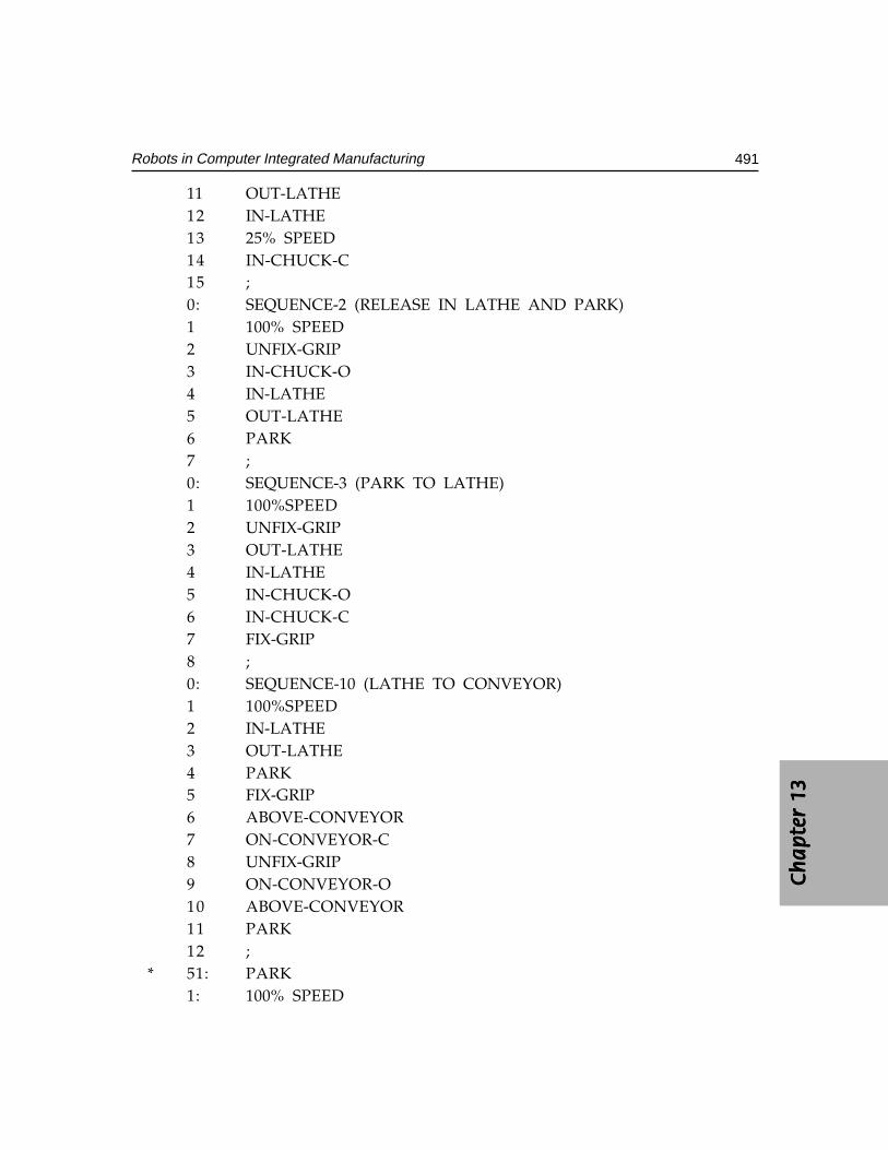
Ch
ap
ter
13C
ha
pte
r 13
Ch
ap
ter
13C
ha
pte
r 13
Ch
ap
ter
13
491Robots in Computer Integrated Manufacturing
11 OUT-LATHE12 IN-LATHE13 25% SPEED14 IN-CHUCK-C15 ;0: SEQUENCE-2 (RELEASE IN LATHE AND PARK)1 100% SPEED2 UNFIX-GRIP3 IN-CHUCK-O4 IN-LATHE5 OUT-LATHE6 PARK7 ;0: SEQUENCE-3 (PARK TO LATHE)1 100%SPEED2 UNFIX-GRIP3 OUT-LATHE4 IN-LATHE5 IN-CHUCK-O6 IN-CHUCK-C7 FIX-GRIP8 ;0: SEQUENCE-10 (LATHE TO CONVEYOR)1 100%SPEED2 IN-LATHE3 OUT-LATHE4 PARK5 FIX-GRIP6 ABOVE-CONVEYOR7 ON-CONVEYOR-C8 UNFIX-GRIP9 ON-CONVEYOR-O10 ABOVE-CONVEYOR11 PARK12 ;
* 51: PARK1: 100% SPEED
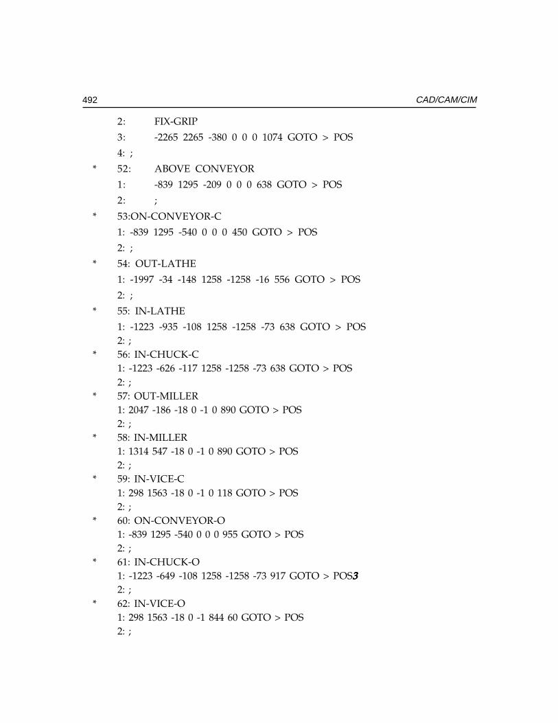
492 CAD/CAM/CIM
2: FIX-GRIP
3: -2265 2265 -380 0 0 0 1074 GOTO > POS
4: ;
* 52: ABOVE CONVEYOR
1: -839 1295 -209 0 0 0 638 GOTO > POS
2: ;
* 53:ON-CONVEYOR-C
1: -839 1295 -540 0 0 0 450 GOTO > POS
2: ;
* 54: OUT-LATHE
1: -1997 -34 -148 1258 -1258 -16 556 GOTO > POS
2: ;
* 55: IN-LATHE
1: -1223 -935 -108 1258 -1258 -73 638 GOTO > POS2: ;
* 56: IN-CHUCK-C1: -1223 -626 -117 1258 -1258 -73 638 GOTO > POS2: ;
* 57: OUT-MILLER1: 2047 -186 -18 0 -1 0 890 GOTO > POS2: ;
* 58: IN-MILLER1: 1314 547 -18 0 -1 0 890 GOTO > POS2: ;
* 59: IN-VICE-C1: 298 1563 -18 0 -1 0 118 GOTO > POS2: ;
* 60: ON-CONVEYOR-O1: -839 1295 -540 0 0 0 955 GOTO > POS2: ;
* 61: IN-CHUCK-O1: -1223 -649 -108 1258 -1258 -73 917 GOTO > POS333332: ;
* 62: IN-VICE-O1: 298 1563 -18 0 -1 844 60 GOTO > POS2: ;
Ch
ap
ter
13C
ha
pte
r 13
Ch
ap
ter
13C
ha
pte
r 13
Ch
ap
ter
13
493Robots in Computer Integrated Manufacturing
13.6 GEOMETRIC REQUIREMENTS FOR THE CAD/ROBOT LINKAGE
The off-line programming system provides the possibility of developing task-orientedand robot-independent user programs. That is, programs can be developed without havinga specific robot in mind. When a task is decomposed into several subtasks, it must bepossible to choose among different co-ordinate frames according to the specified task.For general-purpose applications a reference co-ordinate frame is used, since it allowsthe programmer to easily visualize the motion of the robot in a 3D space. The zero-reference points of the various co-ordinate frames are chosen freely by the programmer,who can then use location-independent information from the CAD database, which isaccessed by any element of the manufacturing system.
To generate the user program, it is necessary to transform the geometric informationof the different co-ordinates, into a common reference co-ordinate frame. This can bedone automatically by the system. The required information to carry out thetransformation is provided by the CAD system. To get an executable user program, atransformation from the Cartesian co-ordinate to the robot co-ordinate system must beperformed. The transformation is necessary for a translation and rotation. The relativeposition and orientation between adjacent co-ordinate frames is calculated with ahomogeneous transformation. With a freely selectable co-ordinate system, task-orientedprogramming is dependent of a special robot. The position of the robot in relation to theworkspace must not be available during programming. However, the exact positiondata must be entered before the program is executed either by a simulator or the robotitself. Changes of the geometric relations between robot and its workspace can be simplycorrelated for. This programming technique is also useful for application to mobile robots.
In an integrated robot programming system, the information generated during theproduct design phase must be available from the CAD database. This includes geometrydata, information on how to process and assemble the work pieces, and data ontechnological requirements for programming. For example, a surface representation of acar body must be carried out to define spot welding points and collision-free robottrajectories. For assemblies, a solid or surface representation is required to computecollision-free trajectories and control surfaces. Also required are task frames (e.g., grasppoints, approach and return direction, and centre of gravity of the component). Standardinterfaces for the exchange of geometric data are available with IGES or with STEP dataexchange formats.
Features of typical simulation software include:Features of typical simulation software include:Features of typical simulation software include:Features of typical simulation software include:Features of typical simulation software include:> Tight integration between simulation systems and solid modeling packages> Real time 3D smooth shaded simulation> Automatic collision detection> Data conversion from CAD models> Extensive robot libraries
494 CAD/CAM/CIM
> Input/output logic simulated between multiple devices> Automatic adjustment of robot work envelope for tool offsets and joint limits.> Real time tele-robotics control and simulation
13.7 SIMULATION
A graphical simulation system for the validation and specification of the robot programis an integral part of an advanced programming system. It must provide a library ofemulated robots, transport devices, and end-effectors to build up a cell model quickly.Modeling capabilities should include modeling the robot’s environment and the robotitself. The mathematics and geometric descriptions of the models depend on the desiredaccuracy of the simulation (2D-or 3D-models, wire frame, surface or solid representation).The graphic representation enables the operator to check the programmed operationsequence. Today, many PC workstations offer high resolution graphics based on theraster graphics technology.
Graphic standards like GKS or PHIGS facilitate the graphic animation of the simulatedrobot. For program alteration an interactive interface is necessary, which allows the use ofa joystick, mouse or light pen. A simulation may be discrete / continuous. Discretesimulation supports programming of the overall control structure of a cell using predicatetransitions. Continuous simulation is used for testing such details of the program as therobot motion, interaction with other components of the cell, and the dynamic behavior ofthe robot.
13.8 ADAPTIVE CONTROL
Adaptive control is the ability to modify a program in real time, based upon sensorydata. Robots can make use of abilities such as orienting parts based on features, followinga changed path, or recognizing work pieces. Adaptive control requires sensory inputand the ability to respond to that input.
Adaptive control will greatly enhance role of the industrial robots in the computerintegrated factory. The robot endowed with ability to adjust to its environment, reducesscrap and rework, and a robot equipped with adaptive control can perform quality - controlfunctions integral with its tasks.
Adaptive control sensors for robots are found in the same general categories as thehuman senses: touch, sound, vision and process related sensors (functionally similarto taste and smell). Sensor input can be used at different levels in the robot hierarchy.Commonly, they are used for robot path or position alteration. Sensors may be used toadaptively control processes being performed by the robot. Sensor data may also sendby the robot to other machines. The physical integration of sensors into the robot
Ch
ap
ter
13C
ha
pte
r 13
Ch
ap
ter
13C
ha
pte
r 13
Ch
ap
ter
13
495Robots in Computer Integrated Manufacturing
structure has been dictated by the specific task to be performed and the properties ofthe sensors.
13.9 ROBOT OPERATION
Robots are used for several applications. Each application requires a certain mode ofoperations. These modes of operation can be classified into four types:
i. Pick-and-place: Pick-and-place: Pick-and-place: Pick-and-place: Pick-and-place: As the name implies, this mode involves a very limited sequenceof moves to a fixed position where it grasps a part (“pick”), then moves to anotherposition where it “places” the part. Some applications may involve several movepositions. The controls involved are generally the simplest. A non-servo controlsystem, with either mechanical stops or pneumatic logic, is adequate. Because ofthe simplicity of the motion and the fixed positions involved, the pick-and-placemode can be accurate and capable of high speed. A typical application is placingthe IC’s on a printed circuit board.
ii. Point-to-point:Point-to-point:Point-to-point:Point-to-point:Point-to-point: This is used for more complex movements where the arm iscontrolled in a series of steps that have been stored in memory. The programmingis usually performed by the use of teach pendant. Although the movement isnormally under servo control, there is no coordinated motion between the axes.Each axis operates at its maximum rate until it reaches the desired endpointposition. The intermediate path, velocity, and relative motion between axes arenot controlled. This is adequate for many applications where only the activity atthe endpoint positions is important. Applications like spot welding are examplesof point to point operations.
iii. Continuous path:Continuous path:Continuous path:Continuous path:Continuous path: This mode is required when the control of the manipulator’spath is critical, such as in a spray-painting application. The robot’s path is notdetermined by a series of pre-programmed points. The path and movement ofeach axis is stored during a walk through programming session. Although thiscreates a continuous path, it is not precise. All the movements of the operatorintended or not, are recorded. A large amount of memory and a high-speedsampling system are needed to record all the path data.
iv. Controlled path: Controlled path: Controlled path: Controlled path: Controlled path: Where the total control of the robot’s motion as in an arc weldingdesired, a detailed control program and sophisticated servo-control system mustbe used. This provides coordinated control of all the axes in terms of theirposition, velocity, and acceleration. The program can optimize the movementsof the manipulator to reduce cycle time, minimize forces, eliminate jerky motions,and improve precision. Sensors provide the necessary feedback to control theprocess. For example vision sensors provide feedback of progress of a roboticwelding operation.
496 CAD/CAM/CIM
13.10 ENDS-OF-ARM-TOOLING
The robot control program must also control any operations involving the end-of-armtooling or gripper. For simple one-step operations, a single output from an on-off switchmay be all that is necessary to activate the gripper. For movements involving a sequenceof several steps, multiple outputs may be required, including those from support fixturesand tools. In complex applications, the control program must integrate all the signals,which can influence the actions of the robot. They may include inputs from other machinesto determine if they are ready to operate. They may also include signals, which notify thesystem that a part is present or that an operation was performed successfully.
13.11 CONTROL SYSTEM OPERATION
During the operation of a robot, the control system is very busy, even for relatively simplemovements. A real-time servo control system executes a series of tasks at a fixed frequency,normally a high-speed sampling rate that has been pre-programmed into the control system.A typical sequence of events goes as follows:
(i) Read input status (e.g., safety interlocks, power on)(ii) Execute program commands (e.g., MOVE)
(iii) Check safety conditions(iv) Monitor sensor values(v) Interpret motion commands
(vi) Output updated joint position goals(vii) Log and terminate processing
13.12 APPLICATIONS OF INDUSTRIAL ROBOTS
Robots are being used for a wide range of tasks in the industry (Fig. 13.11). A study ofthe application wise break-up of industrial robots in U.S. and Japan identifies majorapplication areas to be handling. welding, surface coating, machining and assembly.
Application USA JAPAN
Welding 35% 28.5 %Material 26% 27.5 %Handling/Casting 8 % 9 %Machine Loading 5 % 3.5 %Painting Assembly 16 % 26 %Others 10% 5.5 %
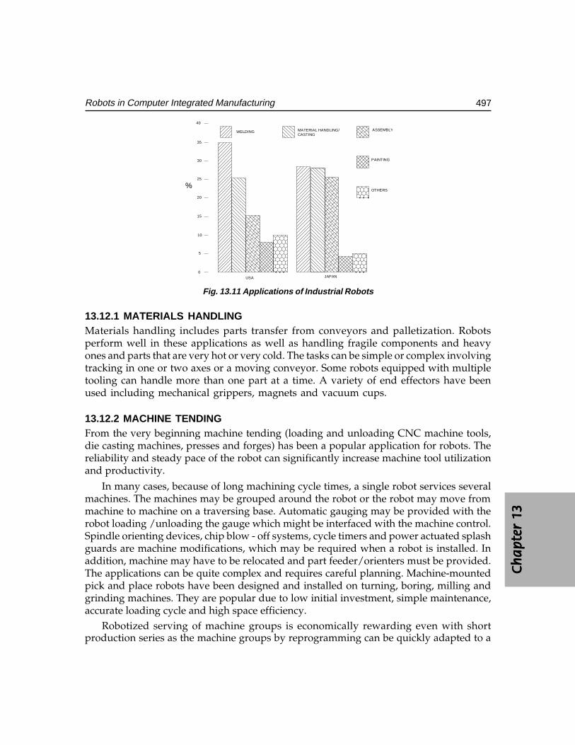
Ch
ap
ter
13C
ha
pte
r 13
Ch
ap
ter
13C
ha
pte
r 13
Ch
ap
ter
13
497Robots in Computer Integrated Manufacturing
0
5
10
15
20
25
30
35
40
WELDING MATERIAL HANDLING/CASTING
ASSEMBLY
PAINTING
OTHERS%
USA JAPAN
Fig. 13.11 Applications of Industrial Robots
13.12.1 MATERIALS HANDLINGMaterials handling includes parts transfer from conveyors and palletization. Robotsperform well in these applications as well as handling fragile components and heavyones and parts that are very hot or very cold. The tasks can be simple or complex involvingtracking in one or two axes or a moving conveyor. Some robots equipped with multipletooling can handle more than one part at a time. A variety of end effectors have beenused including mechanical grippers, magnets and vacuum cups.
13.12.2 MACHINE TENDINGFrom the very beginning machine tending (loading and unloading CNC machine tools,die casting machines, presses and forges) has been a popular application for robots. Thereliability and steady pace of the robot can significantly increase machine tool utilizationand productivity.
In many cases, because of long machining cycle times, a single robot services severalmachines. The machines may be grouped around the robot or the robot may move frommachine to machine on a traversing base. Automatic gauging may be provided with therobot loading /unloading the gauge which might be interfaced with the machine control.Spindle orienting devices, chip blow - off systems, cycle timers and power actuated splashguards are machine modifications, which may be required when a robot is installed. Inaddition, machine may have to be relocated and part feeder/orienters must be provided.The applications can be quite complex and requires careful planning. Machine-mountedpick and place robots have been designed and installed on turning, boring, milling andgrinding machines. They are popular due to low initial investment, simple maintenance,accurate loading cycle and high space efficiency.
Robotized serving of machine groups is economically rewarding even with shortproduction series as the machine groups by reprogramming can be quickly adapted to a
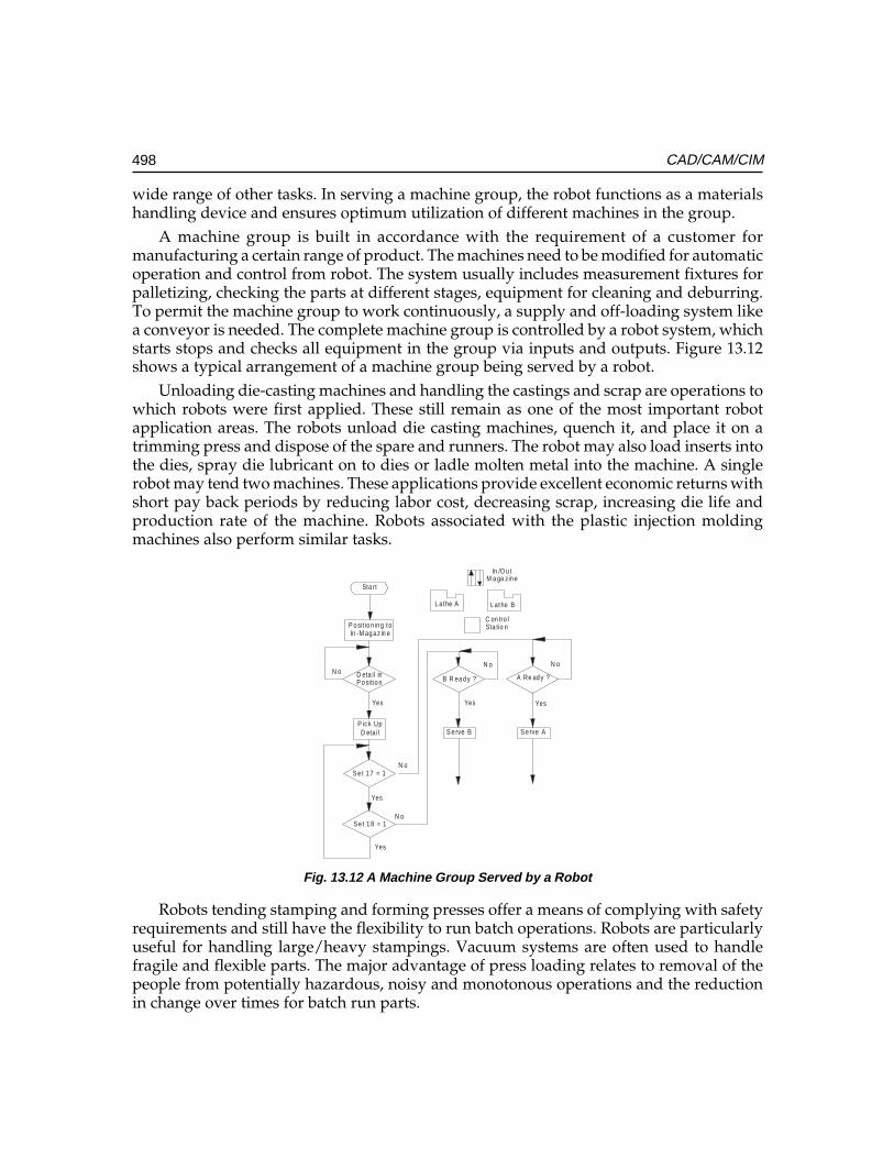
498 CAD/CAM/CIM
wide range of other tasks. In serving a machine group, the robot functions as a materialshandling device and ensures optimum utilization of different machines in the group.
A machine group is built in accordance with the requirement of a customer formanufacturing a certain range of product. The machines need to be modified for automaticoperation and control from robot. The system usually includes measurement fixtures forpalletizing, checking the parts at different stages, equipment for cleaning and deburring.To permit the machine group to work continuously, a supply and off-loading system likea conveyor is needed. The complete machine group is controlled by a robot system, whichstarts stops and checks all equipment in the group via inputs and outputs. Figure 13.12shows a typical arrangement of a machine group being served by a robot.
Unloading die-casting machines and handling the castings and scrap are operations towhich robots were first applied. These still remain as one of the most important robotapplication areas. The robots unload die casting machines, quench it, and place it on atrimming press and dispose of the spare and runners. The robot may also load inserts intothe dies, spray die lubricant on to dies or ladle molten metal into the machine. A singlerobot may tend two machines. These applications provide excellent economic returns withshort pay back periods by reducing labor cost, decreasing scrap, increasing die life andproduction rate of the machine. Robots associated with the plastic injection moldingmachines also perform similar tasks.
Sta rt
P o sitio nin g toIn -M ag a z in e
D eta il inP o sitio n
P ic k UpD eta il
S e t 1 7 = 1
S e t 1 8 = 1
B R ea d y ?
S e rve B
A Re ad y ?
S e rve A
N o N o
Yes Yes
N o
N o
Yes
Yes
Yes
N o
L athe A L athe B
In /O u tM a ga zin e
C on tro lSta tio n
Fig. 13.12 A Machine Group Served by a Robot
Robots tending stamping and forming presses offer a means of complying with safetyrequirements and still have the flexibility to run batch operations. Robots are particularlyuseful for handling large/heavy stampings. Vacuum systems are often used to handlefragile and flexible parts. The major advantage of press loading relates to removal of thepeople from potentially hazardous, noisy and monotonous operations and the reductionin change over times for batch run parts.
Ch
ap
ter
13C
ha
pte
r 13
Ch
ap
ter
13C
ha
pte
r 13
Ch
ap
ter
13
499Robots in Computer Integrated Manufacturing
Robot applications in forging include die forging, upset forging and roll forging. Therobots may load furnaces, forging presses, headers and trim presses and lubricate dies.Special attention is taken to protect the robot from heat and shock loads. The applicationsoffer significant benefits like reduction in labor cost and removal of human labor.
In comparison with traditional production methods, robotized machine group servinghas the following advantages:
• Better utilization of both machines and robot• Shorter throughput time• Improved and more even product quality• increased operational safety• Lower personnel training costs• Partly or completely unmanned production
13.12.3 WELDINGSpot welding was the first major automobile application where robots were usedextensively. This application is proven and so widespread that leading automobilemanufacturers in U.S, Japan, Germany, Italy, U.K, and Sweden have fully automatic weldinglines integrating number of robots, fixturing and transfer services. Robots are also used inIndian automobile industries. The robot’s ability to carry out consistent placement of weldspermit a reduction in number of spot welds required for the same net output.
13.12.3.1 ARC WeldingArc welding is an area for extensive robotic application. Potential robot arc weldingoperations are not only two to three times faster than manual welding but also relieveworkers from exposure to hazardous fumes, radiation and noise and from tasks, whichcall for high degree of concentration and skill. The advantages of the application of a robotto weld sheet metal components include improved and consistent quality of welds andremoval of human operator from a tedious, unpleasant and potentially dangerous task.An example is the welding of header pipes in boilers.
13.12.4 SURFACE COATINGSurface coating operations with robots involve spray application of paint, stain, plasticpowder, sound absorber or similar materials. The robots are normally servo controlledwith six or seven degrees of freedom and are designed to be intrinsically safe for use in avolatile atmosphere. Cost savings in labor, consistent product quality, material savings,energy savings, reduced booth maintenance and relieving workers from exposure to toxicfumes are the advantages claimed for surface coating robotic installations.
13.12.5 MACHININGMachining operations with industrial robots are relatively new area of application.Deburring of machined parts, grinding, polishing, removal of flash from parting lines of
500 CAD/CAM/CIM
forged/cast parts, drilling, routing and riveting of aircraft panels are some of theoperations. Pneumatically or electrically driven tools are usually compliantly mountedon the robot. In some installations the robot handles the work piece against a fixed tool.Robotic machining has the potential to eliminate manual operations, which limits theproduction throughput and aims to eliminate costly tooling aids.
13.12.6 ASSEMBLYPresently most assembly operations are effected manually and they represent a roboticapplication area of significant economic potential. A number of small servo controlledrobots have been developed for assembly functions. Vision and tactile sensing capabilitiesare being developed to this new generation of robots. The inherent economic benefits,improved quality and increased productivity have encouraged research/developmentin this area.
Robots are widely used in automobile assembly. Some of such operations carried outby robots are:
Engine and power train assembly
• fixing flywheels, spring struts, front covers• Front and rear axles• Steering gear
Trim assembly
• Door liners• Wind shield preparation and fitting
Final assembly
• Wheels• Chassis module and body decking
13.12.7 INSPECTIONFor inspection purposes, the robot may be used primarily as a handling device passivelyor it may handle the measuring device itself positioning the gauge in the programmedlocation relative to part inspected. Gauging devices can be either contact devices or lasers.Robotic inspection speeds up the process and assures high reliability of data as well.
13.13 THE INTEGRATION OF THE INDUSTRIAL ROBOT INTO A CIM SYSTEM
The block diagram of an industrial robotic cell is shown in Fig. 13.13.A robot can beprogrammed to serve a number of machines. This makes sense as otherwise the robotwill be under utilized. In the figure the robot is shown to attend four machines. Thework involved may be loading/unloading, deburring etc. Sensors attached to the
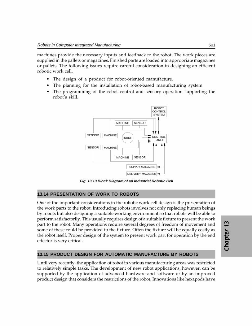
Ch
ap
ter
13C
ha
pte
r 13
Ch
ap
ter
13C
ha
pte
r 13
Ch
ap
ter
13
501Robots in Computer Integrated Manufacturing
machines provide the necessary inputs and feedback to the robot. The work pieces aresupplied in the pallets or magazines. Finished parts are loaded into appropriate magazinesor pallets. The following issues require careful consideration in designing an efficientrobotic work cell.
• The design of a product for robot-oriented manufacture.• The planning for the installation of robot-based manufacturing system.• The programming of the robot control and sensory operation supporting the
robot’s skill.
ROBOT
MACHINE SENSOR
MACHINE
MACHINE
MACHINE
SENSOR
SENSOR
SENSOR
CONTROLPANEL
ROBOTCONTROLSYSTEM
SUPPLY MAGAZINE
DELIVERY MAGAZINE
Fig. 13.13 Block Diagram of an Industrial Robotic Cell
13.14 PRESENTATION OF WORK TO ROBOTS
One of the important considerations in the robotic work cell design is the presentation ofthe work parts to the robot. Introducing robots involves not only replacing human beingsby robots but also designing a suitable working environment so that robots will be able toperform satisfactorily. This usually requires design of a suitable fixture to present the workpart to the robot. Many operations require several degrees of freedom of movement andsome of these could be provided to the fixture. Often the fixture will be equally costly asthe robot itself. Proper design of the system to present work part for operation by the endeffector is very critical.
13.15 PRODUCT DESIGN FOR AUTOMATIC MANUFACTURE BY ROBOTS
Until very recently, the application of robot in various manufacturing areas was restrictedto relatively simple tasks. The development of new robot applications, however, can besupported by the application of advanced hardware and software or by an improvedproduct design that considers the restrictions of the robot. Innovations like hexapods have

502 CAD/CAM/CIM
been incorporated of late in the design of robots. Two research areas can thus bedistinguished: the development of advanced assembly robots and the redesign of theproduct and its components for assembly by robots.
Both of these approaches are important, and they may complement each other. Tilltoday, the first approach was the one mainly pursued by industry. However, the experienceof companies indicates that much greater effort is required to design a product for assemblyrobots. Flexible assembly stations using robots require a standardization of the product orpart of it and unique method for the description of the product assembly system.
13.16. MANUFACTURERS OF ROBOTS
There are a large number of robot manufacturers. Some of the well known manufacturersare listed below:
• Fanuc• Kuka• ABB• Epson• DENSO• Hyundai• Comau• Nachi• Motoman• Adept• ABB• Seiko• Kawasaki• Staubli Unimation• Mitsubishi
QUESTIONS
1. What is the significant advantage of using a Robot in a computer integratedmanufacturing system?
2. Describe the elements of a robotic system.3. How do you justify the use of a robot?4. How do you classify robots?5. Differentiate between a SCARA and a gantry robot.6. Define the work envelope of a robot. How does it differ from one type of robot
to another?

Ch
ap
ter
13C
ha
pte
r 13
Ch
ap
ter
13C
ha
pte
r 13
Ch
ap
ter
13
503Robots in Computer Integrated Manufacturing
7. What are the different types of drives used in robots?8. What are the different types of control systems used in robots?9. How do you specify a robot?
10. What are the different methods of programming of robots?11. Discuss the basic types of robot programming languages.12. How do you integrate CAD data with robot operation?13. Briefly describe significant application areas of robots.14. Discuss the importance of proper presentation of work parts to the robots.15. Determine the effective work envelope of a robot from its specifications.

This pageintentionally left
blank
��������������
������������
������
Quality in manufacturing context can be defined as the degree to which a product or itscomponents conform to certain standards that have been specified by the designer. Thedesign standard generally relates to the materials, dimensions and tolerances, appearance,performance, reliability, and any other measurable characteristics of the product. This chapterdeals with the integration of the quality control function in a CIM system.Using CIM, potential fit and function problems in the actions and interactions of themanufactured part and its tooling and assembly procedure can be analyzed successfullyand remedial action taken earlier.
14.1 INTRODUCTION
Getting anything right first time costs money. However, it also saves money. While thecost of getting it right increases, the cost of getting it wrong decreases. The important thingis to establish the level at which these curves cross and to achieve the optimum in terms ofquality costs. However there is a further factor in the equation i.e. that of customersatisfaction. Quality control, which encompasses inspection, measurement and testing, isa vital part of any manufacturing activity and is applied to ensure consistently high qualityin manufactured goods.
The quality control (QC) function has traditionally been performed using manualinspection methods and statistical sampling procedures. Manual inspection is generally atime consuming procedure, which involves precise, yet monotonous work. Parts may haveto be removed from the vicinity of the production machines to a separate inspection area.This causes delays and often obstructs smooth flow of the components through differentprocesses. Manufacturing schedules are also often upset because of this delay.
Inherent in the use of statistical sampling procedures is acknowledgement of the riskthat some defective parts will slip through. Indeed, statistical quality control implies thata certain expected or average fraction defect rate will be generated during the production/inspection process. The nature of traditional statistical QC procedures is that somethingless than 100% good quality must be tolerated.
506 CAD/CAM/CIM
There is another aspect of statistical QC inspection process, which detracts it from itsusefulness. It is often performed after the parts are already made. If the parts are defectivethey must be scrapped or reworked at an additional cost. There are several economic,social, and technological factors at work to modernize the quality control function. Theeconomic factors include high cost of inspection and desire to eliminate inspection as asource of costly delay in manufacture. The social factors include the ever-increasing demandby customers for near perfection in the quality of manufactured items. The technical factorsconsist of several important advances, which have been made, in inspection automation.
Computer integrated manufacturing attempts to solve this problem in a differentway. This concept is called total quality management.
14.2 TOTAL QUALITY MANAGEMENT (TQM)
In chapter 3, we discussed the application of concurrent engineering to productdevelopment. The total quality management is based on more or less the same philosophy.TQM is based on the assumption that quality cannot be “inspected into” a product; it mustbe “built into” it. That means any amount of inspection after the products or the componentsare manufactured will not help to improve the quality. One must look at the process itselfto avoid production of poor quality products. To ensure this, consideration of the followingaspects is necessary.
i. Quality of design:Quality of design:Quality of design:Quality of design:Quality of design: Primary attribute of a good product is that the quality ofits design must be superior. There are several factors, which influence the designquality.
These include:These include:These include:These include:These include:• Choice of right materials• Selection of appropriate raw material shapes• Design involving minimum number of parts• Use of standardization and variety reduction• Reduction in the material removed during processing• Economic use of materials• Use of standard/bought out parts
A good product can be evolved if the design is analyzed using “Failure Modes, Effectsand Criticality Analysis (FMECA)” as well as “Design for Manufacture and Assembly(DFMA)” techniques. Softwares are now available to carry out this task. The use of FMECAand DFMA techniques will ensure that all the weak aspects of design, which affect productquality and make manufacturing difficult, can be identified and rectified before thedrawings are released for manufacture.
ii. Selection of appropriate process and equipment:Selection of appropriate process and equipment:Selection of appropriate process and equipment:Selection of appropriate process and equipment:Selection of appropriate process and equipment: Proper design of themanufacturing technique plays an important role in the quality of the product.
Ch
ap
ter
14C
ha
pte
r 14
Ch
ap
ter
14C
ha
pte
r 14
Ch
ap
ter
14
507Computer Aided Quality Control
CIM lays great emphasis on manufacturing technology development for newproduct development, which often requires new manufacturing techniques orrefinement of existing technique. However, choice of appropriate technique ofmanufacture is a key issue influencing the quality of the product.
iii. Choice of equipment:Choice of equipment:Choice of equipment:Choice of equipment:Choice of equipment: Choice of process equipment is another vital factor. Theequipment must have the capability to produce parts of requisite quality withoutextra attention on the part of the operator. Since CIM uses equipment likecomputerized machines and handling equipment with integrated processmonitoring and control, this aspect has been well taken care of.
iv. Training of personnel:Training of personnel:Training of personnel:Training of personnel:Training of personnel: One of the important aspects of quality production is thatthe personnel involved in the production must be properly and adequately trainedto carry out their task. They ought to know how to produce the product, withthe required quality. They should be well aware of the quality requirements. Theaxiom “doing it right, the first time, every time” is significant in this context.
Today, every manufacturer is keen to obtain ISO-9000 certification. Implementation ofCIM automatically takes care of many documentation and communication requirementsof ISO-9000, right from product design to testing and shipping, covering the entire gamutof manufacture.
14.3 QC AND CIM
A wide range of computer-based instrumentation is being used for quality control. Inparticular the increased sophistication of sensors and transducers, which are part of CIM,is making it easier to carry out pre-process, in-process, and post-process inspection.Inspection and testing are meant to reduce wastage and make maximum use of resources.
The incorporation of digital techniques in manufacturing systems and the use ofcomputers and microprocessors for controlling manufacturing processes have resulted inthe introduction of several types of inspection techniques. In modern manufacturingsystems, inspection is no longer considered as an appraisal oriented process (ACCEPTED/REJECTED) but as prevention oriented process. At present, inspection with the use ofcomputers has acquired a status of its own known as COMPUTER AIDED INSPECTION(CAI) and is an integral part of Computer Integrated Manufacturing.
The present day concern in any manufacturing shop is to ensure that every componentand the end product produced should meet an established and well-defined quality levels.It should also to aim at a cost effective inspection system. This calls for an inspection system,which should be able to track the production process, and which has the potential forproviding information to implement corrective action before the process goes out of control.This can be carried out by both contact type and non-contact type inspection which cancollect the data not only to qualify or classify a component but also to correct themanufacturing process that may cause undesirable deviation. The additional advantagesof non-contact type systems are the instant data collection and data evaluation with less
508 CAD/CAM/CIM
human effort. In addition to this, integration of the latest measuring systems with themanufacturing activities and use of computer for controlling, directing, machining,inspecting etc., result in the total integration of manufacturing.
14.4 INSPECTION AND TESTING
Inspection is normally used to examine whether a product conforms to the designstandards specified for it. For a mechanical component, this would be probably concernedwith the dimensions, surface texture and tolerances specified for the part. Non-conforminggoods result in scrap, rework, and the loss of customer goodwill.
The common situations that warrant inspection are:The common situations that warrant inspection are:The common situations that warrant inspection are:The common situations that warrant inspection are:The common situations that warrant inspection are:
• Incoming materials (raw materials, standard items, subcontracted parts)• Stage inspection during manufacturing (e.g., when the parts are moved from
one production section to another)• At the completion of processing of the parts• Before shipping the final assembled product to the customer.
Whereas inspection is a regular activity in production, testing is a significant stageof work in product development to prove the capability of the product. Testing isnormally associated with the functional aspect of item, and is often directed at thefinal product rather than its components. Testing consists of the appraisal of theperformance of the final product under actual or simulated conditions. If the productsuccessfully passes the tests, it is deemed suitable for use. Testing ascertains the qualityof performance of the product.
Various categories of tests used for final product evaluation are listed below:Various categories of tests used for final product evaluation are listed below:Various categories of tests used for final product evaluation are listed below:Various categories of tests used for final product evaluation are listed below:Various categories of tests used for final product evaluation are listed below:
• Functional tests under normal or simulated operating conditions• Fatigue or wear tests to determine the product’s life function until failure• Overload tests to determine the level of safety factor built into the product• Environmental testing to determine how well the product will perform under
different environments (e.g. humidity, temperature, vibration).Another test that is often resorted to is destructive testing. This is a procedure that
results in destruction of the item in order to measure the property of interest. A commonexample is the tensile test on a metal specimen to determine the metal’s strength andductility properties. Destructive testing is often employed as an inspection procedure,because it is often applied to raw materials, partially processed materials and componentparts. It can also be applied to the final product. However, destructive test for final productsis very expensive and would be done on a very limited sampling basis. Tests at the prototypestage yield valuable information for product improvement.
Ch
ap
ter
14C
ha
pte
r 14
Ch
ap
ter
14C
ha
pte
r 14
Ch
ap
ter
14
509Computer Aided Quality Control
14.5 STATISTICAL PROCESS CONTROL (SPC)
A controlled production process is one in which only random causes influence qualityvariation. It means that the process parameters which affect the variability of the processis well under control and the process monitoring mechanism can detect any significantchange in the process. Statistical process control (SPC) is widely employed in CIM to exerciseprocess control. SPC uses X charts, R charts and SIGMA charts to monitor process variability.Measuring instruments are directly linked to microprocessor-based equipment to processthe data and display results.
Several SPC instruments are now available in the market. These instruments includehand held instruments as well as PC based systems. Control charts, Pareto charts, histogramsand full SPC analysis can be done using these equipments. Data entry to an instrument iseither manually, via the keyboard, or directly from a gauge.
14.6 OBJECTIVES OF CAQC
The objectives of computer-aided quality control are to:The objectives of computer-aided quality control are to:The objectives of computer-aided quality control are to:The objectives of computer-aided quality control are to:The objectives of computer-aided quality control are to:
i. Improve product qualityii. Increase productivity in the inspection process
iii. Increase productivityiv. Reduce lead-timev. Reduce wastage due to scrap/rework
The strategy for achieving these objectives is basically to automate the inspectionprocess through the application of computers combined with sensor technology. Wheretechnically possible and economically feasible, inspection should be done on a 100%basis rather sampling.
14.7 ROLE OF COMPUTER IN QC
Computer-aided inspection (CAI) and computer aided testing (CAT) are the two majorsegments of computer-aided quality control. Whereas these activities have been traditionallyperformed manually (with the help of gauges, measuring devices and testing apparatus),CAI and CAT are performed automatically using computer and sensor technology. Today,CAI and CAT can be well integrated into the overall CIM system.
The implications of the use of computer-aided quality control are important. Theautomated methods of CAQC will result in significant improvements in product quality.The following list summarizes the important benefits of CAQC.
i. With Computer aided inspection and computer aided testing inspection andtesting will typically be done on a 100% basis rather by the sampling procedures
510 CAD/CAM/CIM
normally used in traditional QC. This eliminates any problem in assembly laterand therefore is important in CIM.
ii. Inspection is integrated into the manufacturing process. This will help to reducethe lead-time to complete the parts.
iii. The use of non-contact sensors is recommended for computer aided inspectionand CIM. With contact inspection devices, the part must be stopped and oftenrepositioned to allow the inspection device to be applied properly. These activitiestake time. With non-contact sensing devices the parts can be inspected while inoperation. The inspection can thus be completed in a fraction of a second.
iv. The on-line non-contact sensors are useful as the feedback element of adaptivecontrol systems. These systems will be capable of making adjustments to theprocess variables based on analysis of the data including trend analysis. Anexample of the application of trend analysis can be found in the compensationof gradual wear of cutting tool in a machining operation. This would not onlyhelp to identify out-of-tolerance conditions but also to take corrective action. Byregulating the process in this manner, parts will be made much closer to thedesired nominal dimension rather than merely within tolerance. This will helpto reduce scrap losses and improve product quality.
v. Sensor technology will not be the only manifestation of automation in CAQC.Intelligent robots fitted with computer vision and other sensors, as an integralpart of completely automated test cells is also a feature of CIM.
vi. An important feature of QC in a CIM environment is that the CAD/CAM databasewill be used to develop inspection plan.
As mentioned earlier inspection can be either contact or non-contact type. The contactmethod usually involves the use of coordinate measuring machines (CMM).
14.8 COORDINATE MEASURING MACHINE
The coordinate measuring machine (CMM) is the most prominent example of theequipment used for contact inspection of parts. When used for CIM these machines arecontrolled by CNC. A typical three-dimensional measuring machine consists of a table,which holds the part in a fixed, position, and movable head, which holds a sensing,probe. The probe can be moved in three directions corresponding to the X, Y and ZCoordinates. For manual operation, the control unit is provided with joysticks, or otherdevices which drive X, Y and Z servo motors (AC/DC).
During operation, the probe is brought into contact with the part surface to bemeasured and the three co-ordinate positions are indicated to a high level of accuracy.Typical accuracies of these machines are in the neighborhood of + 0.004 mm with aresolution of 0.001 mm. The measuring accuracy of a typical CMM is quoted 2.6 +L/300 micrometers, where L is the measured length in mm.
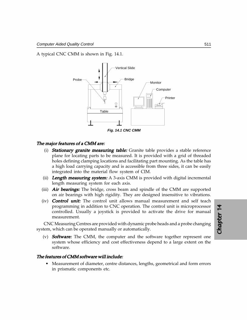
Ch
ap
ter
14C
ha
pte
r 14
Ch
ap
ter
14C
ha
pte
r 14
Ch
ap
ter
14
511Computer Aided Quality Control
A typical CNC CMM is shown in Fig. 14.1.
Vertical Slide
Bridge
Table
ProbeMonitor
Computer
Printer
+.
Fig. 14.1 CNC CMM
The major features of a CMM are:The major features of a CMM are:The major features of a CMM are:The major features of a CMM are:The major features of a CMM are:(i) Stationary granite measuring table: Stationary granite measuring table: Stationary granite measuring table: Stationary granite measuring table: Stationary granite measuring table: Granite table provides a stable reference
plane for locating parts to be measured. It is provided with a grid of threadedholes defining clamping locations and facilitating part mounting. As the table hasa high load carrying capacity and is accessible from three sides, it can be easilyintegrated into the material flow system of CIM.
(ii) Length measuring system:Length measuring system:Length measuring system:Length measuring system:Length measuring system: A 3-axis CMM is provided with digital incrementallength measuring system for each axis.
(iii) Air bearings:Air bearings:Air bearings:Air bearings:Air bearings: The bridge, cross beam and spindle of the CMM are supportedon air bearings with high rigidity. They are designed insensitive to vibrations.
(iv) Control unit:Control unit:Control unit:Control unit:Control unit: The control unit allows manual measurement and self teachprogramming in addition to CNC operation. The control unit is microprocessorcontrolled. Usually a joystick is provided to activate the drive for manualmeasurement.
CNC Measuring Centres are provided with dynamic probe heads and a probe changingsystem, which can be operated manually or automatically.
(v) Software:Software:Software:Software:Software: The CMM, the computer and the software together represent onesystem whose efficiency and cost effectiveness depend to a large extent on thesoftware.
The features of CMM software will include:The features of CMM software will include:The features of CMM software will include:The features of CMM software will include:The features of CMM software will include:
• Measurement of diameter, centre distances, lengths, geometrical and form errorsin prismatic components etc.
512 CAD/CAM/CIM
• On-line statistics for statistical information in a batch.• Parameter programming to minimize CNC programming time of similar parts.• Measurement of plane and spatial curves.• Data communications.• Digital input and output commands for process integration.• Programs for the measurement of spur, helical, bevel and hypoid gears.• Interface to CAD software.
Typical software may also provide a generalized method for reverse engineering complexshaped objects. The component is digitized, taking a dense set of points, using a CNC CMM.The digitized data is then converted into a computer model, which describes the true surfaceof the component, with allowance for the digitizing probe diameter. The model may then beexpanded, offset or mirrored to an allowance for the manufacturing process.
Recent advances in CMM technology are based largely on greater intelligence featuresprovided by the computer software. These advances include the capability for automaticwork part alignment on the table, interactive programming of the CMM for inspectionpersonnel who are not experienced in the use of computers. Besides this, the software hasthe capability to orient the coordinate system as required (between polar and Cartesiancoordinate systems). Similarly translation of origin can be effected as desired.
Savings in inspection time by using CMM are significant. Typically between 5 and10% of the time is required on a CMM compared to traditional manual inspection methods.Other advantages include consistency in the inspection process from one part to the next,which cannot be matched by manual inspection, and reductions in production delays toget approval of the first workpiece in a batch.
14.8.1 ADVANTAGES OF CNC OPERATION OF CMMCNC operation increases cost effectiveness through the following advantages:
i. Shorter measuring timesii. Higher throughput rates
iii. Better repeatabilityiv. Economical even for small batchesv. Simple operation
vi. Unmanned second and third shift inspection of parts if parts are loadedautomatically.
14.9 NON-CONTACT INSPECTION METHODS
The field of non-contact inspection, in particular optical inspection is composed of thefollowing basic areas:
Ch
ap
ter
14C
ha
pte
r 14
Ch
ap
ter
14C
ha
pte
r 14
Ch
ap
ter
14
513Computer Aided Quality Control
i. Inspection of part dimensions.ii. Inspection of surface defects.
iii. Inspection of completed or semi-completed parts.
The main advantages of non-contact inspection are:The main advantages of non-contact inspection are:The main advantages of non-contact inspection are:The main advantages of non-contact inspection are:The main advantages of non-contact inspection are:
i. It eliminates the need to reposition the workpiece.ii. Non-contact inspection is faster than contact inspection.
iii. There is no mechanical wear encountered in the contact inspection probe.iv. The possibility of damage to the surface of a part due to measuring pressure
is eliminated.
Some of the examples of non-contact inspection are laser interferometer measuringsystem, laser telemetric measuring system, machine vision system and optical gauging.These are discussed below.
14.9.1 LASER INTERFEROMETER MEASURING SYSTEMPresently lasers are used as length measuring devices. They are commonly used forpositional accuracy measurements. They are also used as length measuring machines ofhigh accuracy (accuracy of the order of 0.01 micrometer). The feed back of this can be usedfor positioning of the machine and also for computation of measurements.
Nowadays it has become a common practice to use laser-measuring system for thecalibration of CNC machines. Using laser-measuring system the measurements performedare reliable, accurate and faster compared to conventional methods. The laserinterferometer can be directly interfaced with a computer. This makes it easy for theoperator to evaluate the results as per the evaluation procedures mentioned in variousstandards like AMT, AFNOR, VDI, MTTA, and JIS etc. Using different attachments laserinterferometer is also used for other measurements like straightness, flatness, squareness,velocity, pitch, yaw etc.
14.9.2 LASER TELEMETRIC MEASURING SYSTEMSThis is a high speed gauging system providing accuracy and repeatability of a contact typegauge with versatility of a non-contact type of gauge. The principle is explained below:
A thin band of laser beam projects from a transmitter to receiver. When an object isplaced across the beam, the object casts a shadow. The signal from light entering the receiveris used by the microprocessor to detect the shadow and to calculate the dimensionrepresented by the distance between the edges of the shadow.
The system consists of three modules:The system consists of three modules:The system consists of three modules:The system consists of three modules:The system consists of three modules:
i. Transmitter moduleii. Receiver module
iii. Processor electronics
514 CAD/CAM/CIM
The transmitter module contains a low power He-Ne gas laser and its power supply,a specially designed collimating lens, a synchronous motor, multi-faced reflector prism,a synchronous pulse detector and protective window. This produces a collimated parallelscanning laser beam moving at a high and constant speed. The scanning beam appearsas a line of red light. The receiver module collects and photo electrically senses the laserlight transmitted past the object being measured. The processor electronics takes thereceiver signals and converts them to digital signal and displays the dimensions beinggauged.
The information thus collected is processed not only to qualify or classify a part butalso can be used to correct the manufacturing process that might have caused theundesirable deviation. This is done automatically without touching the part and withoutthe need for human intervention. The microprocessor actuates precise computer control ofcontinuously manufactured parts. The prompting formats guide the operator regardingthe gauge setting. The operational procedures notify the operator in case any error occursin the system by displaying error message on the CRT terminal. It also keeps the operatorinformed about the product in the production process, displays, prints out and records thecomplete measured and analyzed results.
Laser telemetric measuring systems give out a number of signal outputs and processingoptions to make the dimensional measurement more useful in production environment.Examples are listed below:
i. A high/low limit alarm option, which activates lights and connector panel, outputwhen the tolerance limits are exceeded.
ii. A process control option, which makes it possible to provide a closed loopcontrol of the diameter of a continuously processed product. The chart recorderand instrumentation interface provide both an analog output for plotting deviationand a RS-232C for digital transmission of other instruments and controls.
14.9.3 VISION SYSTEMA vision system can be defined as a system for automatic acquisition and analysis ofimages to obtain desired data for interpreting or controlling an activity. In a broadersense, the term is applied to a wide range of non-contact electro-optical sensing techniquesfrom simple triangulation and profiling to a 3D object recognition technique. These arebased on sophisticated computerized image analysis routines. The applications rangefrom relatively simple detection and measuring tasks to full-blown robot control, whichinclude quality assurance, sorting, material handling and process control, robot guidance,calibration and testing, machine monitoring and safety.
The schematic diagram of a typical vision system is shown in Fig 14.2. This systeminvolves image acquisition, image processing or image analysis and interpretation.Acquisition requires appropriate lighting, the use of electronic camera and means ofstoring a digital representation of the image. Processing involves manipulating the digitalimage to simplify and reduce number of data points that must be handled by subsequentanalytical routines used to interpret the data. Computers with suitable softwares areused for this purpose.
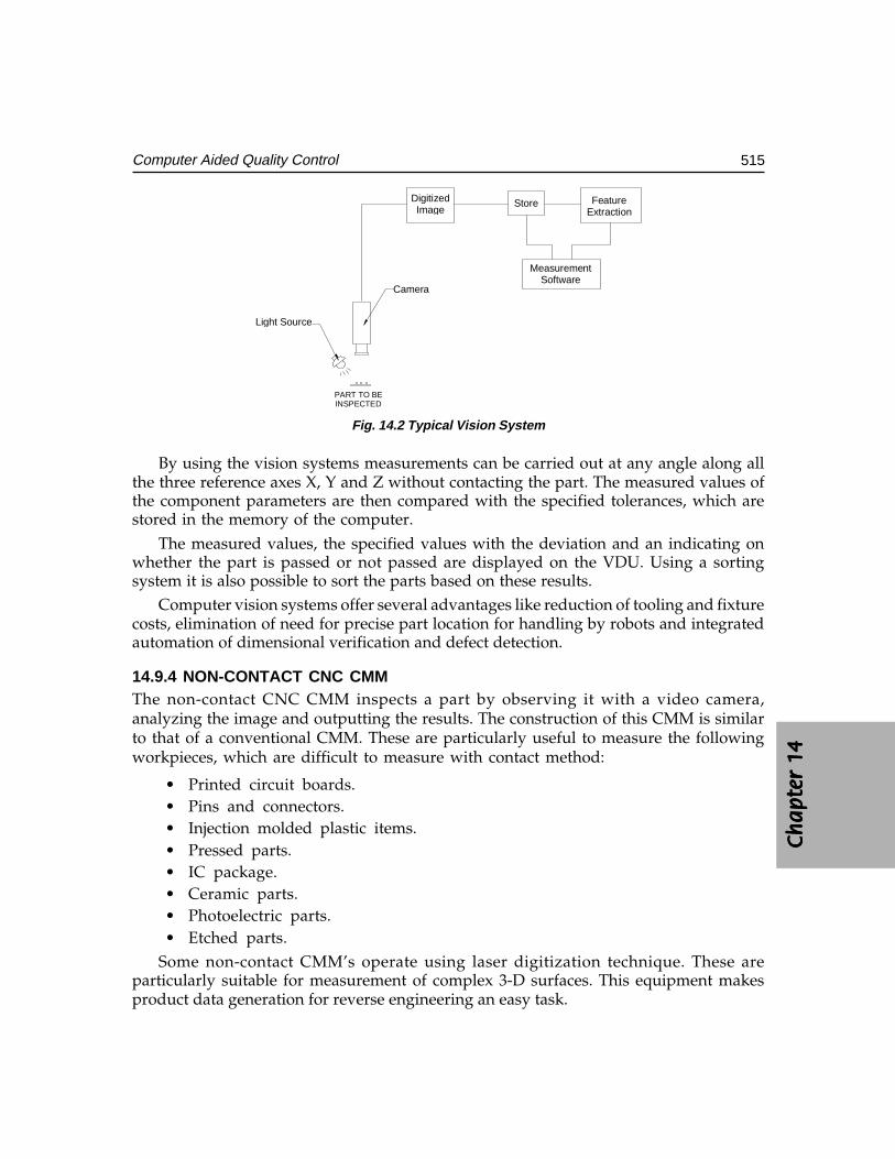
Ch
ap
ter
14C
ha
pte
r 14
Ch
ap
ter
14C
ha
pte
r 14
Ch
ap
ter
14
515Computer Aided Quality Control
DigitizedImage
Store FeatureExtraction
MeasurementSoftware
Camera
Light Source
PART TO BEINSPECTED
Fig. 14.2 Typical Vision System
By using the vision systems measurements can be carried out at any angle along allthe three reference axes X, Y and Z without contacting the part. The measured values ofthe component parameters are then compared with the specified tolerances, which arestored in the memory of the computer.
The measured values, the specified values with the deviation and an indicating onwhether the part is passed or not passed are displayed on the VDU. Using a sortingsystem it is also possible to sort the parts based on these results.
Computer vision systems offer several advantages like reduction of tooling and fixturecosts, elimination of need for precise part location for handling by robots and integratedautomation of dimensional verification and defect detection.
14.9.4 NON-CONTACT CNC CMMThe non-contact CNC CMM inspects a part by observing it with a video camera,analyzing the image and outputting the results. The construction of this CMM is similarto that of a conventional CMM. These are particularly useful to measure the followingworkpieces, which are difficult to measure with contact method:
• Printed circuit boards.• Pins and connectors.• Injection molded plastic items.• Pressed parts.• IC package.• Ceramic parts.• Photoelectric parts.• Etched parts.
Some non-contact CMM’s operate using laser digitization technique. These areparticularly suitable for measurement of complex 3-D surfaces. This equipment makesproduct data generation for reverse engineering an easy task.
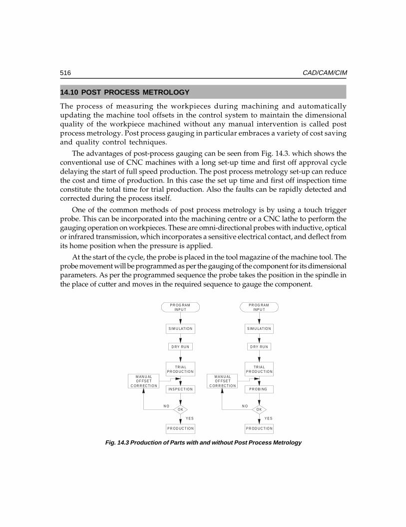
516 CAD/CAM/CIM
14.10 POST PROCESS METROLOGY
The process of measuring the workpieces during machining and automaticallyupdating the machine tool offsets in the control system to maintain the dimensionalquality of the workpiece machined without any manual intervention is called postprocess metrology. Post process gauging in particular embraces a variety of cost savingand quality control techniques.
The advantages of post-process gauging can be seen from Fig. 14.3. which shows theconventional use of CNC machines with a long set-up time and first off approval cycledelaying the start of full speed production. The post process metrology set-up can reducethe cost and time of production. In this case the set up time and first off inspection timeconstitute the total time for trial production. Also the faults can be rapidly detected andcorrected during the process itself.
One of the common methods of post process metrology is by using a touch triggerprobe. This can be incorporated into the machining centre or a CNC lathe to perform thegauging operation on workpieces. These are omni-directional probes with inductive, opticalor infrared transmission, which incorporates a sensitive electrical contact, and deflect fromits home position when the pressure is applied.
At the start of the cycle, the probe is placed in the tool magazine of the machine tool. Theprobe movement will be programmed as per the gauging of the component for its dimensionalparameters. As per the programmed sequence the probe takes the position in the spindle inthe place of cutter and moves in the required sequence to gauge the component.
P R OG RAMINP U T
S IM U LAT IO N
D RY RU N
TR IA LP R OD UC TIO N
INS P E C TIO N
O K
P R OD UC TIO N
Y E S
N O
M AN U ALO F FS E T
C OR R EC TIO N
P R OG RAMINP U T
S IM U LAT IO N
D RY RU N
TR IA LP R OD UC TIO N
O K
P R OD UC TIO N
Y E S
N O
M AN U ALO F FS E T
C OR R EC TIO NP R OB ING
Fig. 14.3 Production of Parts with and without Post Process Metrology
Ch
ap
ter
14C
ha
pte
r 14
Ch
ap
ter
14C
ha
pte
r 14
Ch
ap
ter
14
517Computer Aided Quality Control
The signals from the probe will be transmitted to the control system to initiate thecorrective action. After incorporating the correction through tool offset, the full speedproduction will be started.
The general applications of probe systems are given below:The general applications of probe systems are given below:The general applications of probe systems are given below:The general applications of probe systems are given below:The general applications of probe systems are given below:InspectionComponent verificationIn-cycle gaugingDigitizingTool settingJob set upTool breakage detection
The data from the probe systems can be communicated to the machine control unitin three ways:
a. Inductive transmissionb. Hard-wired transmissionc. Optical transmission
The actual gauging cycle, contained in the part programme, is brought into actionbetween cutting cycles. Based on the information received from the measuring systemcorrective action through appropriate offset values will be incorporated in the system tomachine the component to the required size.
14.11 COMPUTER AIDED INSPECTION USING ROBOTS
Robots can be used to carry out inspection or testing operations for mechanicaldimensions and other physical characteristics and product performance. Generallyrobot must work with other pieces of equipment in order to perform the operations.Examples include machine vision systems, robot manipulated inspection and/ortesting equipment.
Checking robot, programmable robot, and co-ordinate robot are some of the titlesgiven to multi-axis measuring machines aimed at high-speed measurement. Thesemachines automatically perform all the basic routines of a CNC co-ordinate measuringmachine but at a faster rate than that of a CMM. These machines are designed to be usedin environments such as shop floor. They are not as accurate as precision CMM’s butthey can check up to accuracies of 5 micrometres which is often sufficient for manyapplications. However, quality levels can be improved by increasing the number ofinspections. By using robots the dimensional drifts can be accurately and quickly detected
518 CAD/CAM/CIM
and the appropriate process action can be taken. One example is, segregating thecomponents according to the tolerance specifications.
Using the modern touch trigger probe, a co-ordinate robot or a pair of robots cantake successive readings at high speed and evaluate the results using a computer graphicsbased real time statistical analysis system. This gives high-speed data processing ofmeasured information and can provide early warning of rejection. The computer alsomonitors the geometry and wear of the tools, which produce the component. After themeasurement, if the component is not acceptable it is placed on a conveyor where itslides under gravity into REJECT bin.
14.12 INTEGRATED COMPUTER AIDED INSPECTION SYSTEMS
Automation in industries is intended to provide a batch oriented manufacturing. Theintegration of the activities starting from design to the part coming out of the factory leadsto total automation. This closes the loop in a computer integrated manufacturing system.Some of the integrated systems are available in different configurations, examples beingintegrated CAD/CAM/CAI Systems with robots etc. Some of these are discussed in thefollowing sections:
14.12.1 INTEGRATION OF CAD/CAM WITH INSPECTION SYSTEMCAD/CAM systems are seen as a natural adjunct to automatic gauging wherein aproduct is designed, manufactured and inspected in one automatic process. There is astrong trend in the direction of a closed loop, fully adaptive manufacturing system.
One of the critical factors in manufacturing quality assurance is to ensure thatevery part coming off the production line is within design tolerance. The successfulfactory constantly monitors quality at each step of design and manufacturing process.In the shop, the coordinate measuring machine assists in this quality assurancefunction. The productivity of the coordinate measuring machine can be improved byinterfacing with a CAD/CAM system. Interfacing with the CAD/CAM database, theoperator can use the off-line programming capabilities of the CMM interface to processthe input values for the part geometry being measured. This eliminates the laboriousmanual data entry techniques and reduces preparation time and increases availabilityof CMM for inspection.
The CAD/CAM-CMM interface helps the programming efforts in the quality assuranceoffice where quick response to engineering changes can be made and current data to theCMM can be provided. Generally the CAD/CAM-CMM interface consists of a numberof modules as shown in Fig. 14.4.
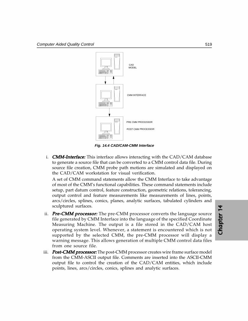
Ch
ap
ter
14C
ha
pte
r 14
Ch
ap
ter
14C
ha
pte
r 14
Ch
ap
ter
14
519Computer Aided Quality Control
CADMODEL
CMM INTERFACE
PRE CMM PROCESSOR
POST CMM POCESSOR
Fig. 14.4 CAD/CAM-CMM Interface
i. CMM-Interface:CMM-Interface:CMM-Interface:CMM-Interface:CMM-Interface: This interface allows interacting with the CAD/CAM databaseto generate a source file that can be converted to a CMM control data file. Duringsource file creation, CMM probe path motions are simulated and displayed onthe CAD/CAM workstation for visual verification.A set of CMM command statements allow the CMM Interface to take advantageof most of the CMM’s functional capabilities. These command statements includesetup, part datum control, feature construction, geometric relations, tolerancing,output control and feature measurements like measurements of lines, points,arcs/circles, splines, conics, planes, analytic surfaces, tabulated cylinders andsculptured surfaces.
ii. Pre-CMM processor:Pre-CMM processor:Pre-CMM processor:Pre-CMM processor:Pre-CMM processor: The pre-CMM processor converts the language sourcefile generated by CMM Interface into the language of the specified CoordinateMeasuring Machine. The output is a file stored in the CAD/CAM hostoperating system level. Whenever, a statement is encountered which is notsupported by the selected CMM, the pre-CMM processor will display awarning message. This allows generation of multiple CMM control data filesfrom one source file.
iii. Post-CMM processor:Post-CMM processor:Post-CMM processor:Post-CMM processor:Post-CMM processor: The post-CMM processor creates wire frame surface modelfrom the CMM-ASCII output file. Comments are inserted into the ASCII-CMMoutput file to control the creation of the CAD/CAM entities, which includepoints, lines, arcs/circles, conics, splines and analytic surfaces.
PROCESSOR
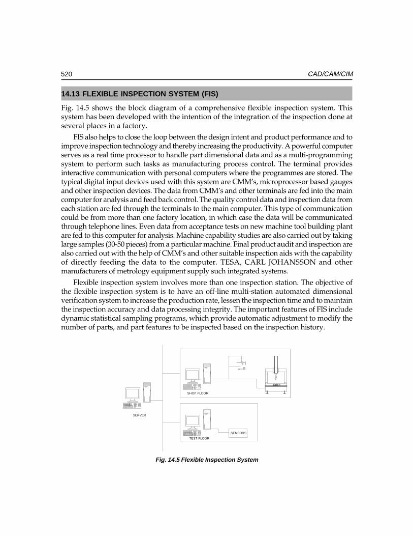
520 CAD/CAM/CIM
14.13 FLEXIBLE INSPECTION SYSTEM (FIS)
Fig. 14.5 shows the block diagram of a comprehensive flexible inspection system. Thissystem has been developed with the intention of the integration of the inspection done atseveral places in a factory.
FIS also helps to close the loop between the design intent and product performance and toimprove inspection technology and thereby increasing the productivity. A powerful computerserves as a real time processor to handle part dimensional data and as a multi-programmingsystem to perform such tasks as manufacturing process control. The terminal providesinteractive communication with personal computers where the programmes are stored. Thetypical digital input devices used with this system are CMM’s, microprocessor based gaugesand other inspection devices. The data from CMM’s and other terminals are fed into the maincomputer for analysis and feed back control. The quality control data and inspection data fromeach station are fed through the terminals to the main computer. This type of communicationcould be from more than one factory location, in which case the data will be communicatedthrough telephone lines. Even data from acceptance tests on new machine tool building plantare fed to this computer for analysis. Machine capability studies are also carried out by takinglarge samples (30-50 pieces) from a particular machine. Final product audit and inspection arealso carried out with the help of CMM’s and other suitable inspection aids with the capabilityof directly feeding the data to the computer. TESA, CARL JOHANSSON and othermanufacturers of metrology equipment supply such integrated systems.
Flexible inspection system involves more than one inspection station. The objective ofthe flexible inspection system is to have an off-line multi-station automated dimensionalverification system to increase the production rate, lessen the inspection time and to maintainthe inspection accuracy and data processing integrity. The important features of FIS includedynamic statistical sampling programs, which provide automatic adjustment to modify thenumber of parts, and part features to be inspected based on the inspection history.
Table
SENSORS
SHOP FLOOR
TEST FLOOR
SERVER
Fig. 14.5 Flexible Inspection System
Ch
ap
ter
14C
ha
pte
r 14
Ch
ap
ter
14C
ha
pte
r 14
Ch
ap
ter
14
521Computer Aided Quality Control
QUESTIONS
1. What is the significance of quality control in CIM?2. Define total quality management and explain its relevance to CIM.3. What are the objectives of computer aided quality control?4. Discuss the important benefits of computer-aided quality control.5. Explain the method of part inspection using a CMM.6. What are the important features available in CMM software?7. Discuss major non-contact inspection methods.8. What is the working principle of computer vision systems?9. How is post-process metrology incorporated in CNC Machines?
10. Describe the features of a flexible inspection system.11. Discuss the integration of CAD database and CMM operation.

This pageintentionally left
blank
���������������
��� ������
�������
Communication is the nervous system of CIM and thus is an integral part of CIM. Thedevelopments in communication engineering have made implementation of CIM easierthan before. This chapter presents a brief overview of fundamentals of networking ofcomputers and introduces the concepts of enterprise wide networking. The potential ofInternet and workflow automation software in the implementation of CIM is also emphasized.
15.1 INTRODUCTION
Data is defined as the raw, unorganized information that is available on each componentof a CIM system like a PC, Robot, and Workstation or CNC machine. Normally, eachcomponent wants access to all the necessary data to make decisions. This means eachcomponent in a CIM system, can take advantage of all the available information to achievehigher reliability, more optimal processing or manufacturing and higher throughput.Networks allow channels of communications to exist among various sections of amanufacturing system. Real-time modifications to business plans can be effected viacommunications through the network. Networks are essential to move information fasteracross various users or various segments of CIM. For example, while the design is beingcompleted, if the manufacturing engineer has access to the design data of the component,the engineer can plan fixture design and start creating the program for manufacture. Theprocess-planning engineer can select a suitable machine tool to machine the component.These are typical cases where time can be saved.
Networks are today integral parts of CIM systems, which have made data sharingeasy, peripheral changing or interfacing easy and information sharing possible.
15.2 PRINCIPLES OF NETWORKING
Advances in technology have been adding more processing power into smallercomputers. The trend has been to move away from massive, centralized computers, whichhandle every task to networks of smaller desktop computers, each closely tailored to aparticular application.
524 CAD/CAM/CIM
From the manufacturing standpoint, this eliminates the possibility of shutting downthe entire plant if a large central computer fails. It is easier to replace a defective PC. Moredesktop computers can be added to the network depending on the need. Thus, the networkis scalable. Networking also allows incremental growth of the overall system with minimalinvestment and disruption.
Networking is a convenient technique for tying together the various “islands ofautomation” which were discussed in Chapter 1 and in the process makes integrationpossible through high-speed data exchange between different automated segments.
Networking of computers was initially adopted successfully by service sectors likebanking, airline and train reservation etc. and later was introduced in manufacturingindustries. Today, many designs involve collaborative efforts of hundreds of engineers.Networked systems facilitate quick information exchange and effectively cut downdevelopment lead-time. Some examples are:
(i) Design and development of VLSI and UVLSI chips like microprocessors.(ii) Design and manufacture of aircrafts and automobiles.
Communication networks can be classified into four categories depending upon thephysical separation of the communicating devices:
(i) Miniature (< 50 m): Such networks are concerned with the interconnection ofmultiple computational elements.
(ii) Small (< 500 m): These are concerned with the interconnection of multiplecomputational units.
(iii) Medium (< 1 km usually): These networks are concerned with the interconnectionof multiple computational units (office workstations, CAD systems, shop floorcomputers and data collection terminals, CNC systems, Robots etc.). These areconnected through a Local Area Network (LAN), or Intranet. LAN may coverdistances more than one 1 km too.
(iv) Large (> 1 km): Large networks involve connection of remote mainframes,networking of a minicomputer system to a remote mainframe or terminals etc.It can be citywide (Metropolitan Area Network-MAN) or countrywide orWorldwide-WAN). With Internet becoming more and more popular, the intranet-internet-extranet technologies have found favour with manufacturing companies.
15.2.1 PRIVATE COMPUTER COMMUNICATION NETWORKSA manufacturing industry may have a number of plants situated at different locations in acountry or in different continents. There is need for them to communicate each other toshare resources and exchange information. An autonomous data communication networkfor this purpose is called a private computer communication network. The technologyinvolved in such a network is discussed in detail later in this chapter. However Intranetsand Extranets provide powerful, convenient and cost effective alternatives.
Ch
ap
ter
15C
ha
pte
r 15
Ch
ap
ter
15C
ha
pte
r 15
Ch
ap
ter
15
525Fundamentals of Networking
15.2.1.1 Virtual Private Network (VPN)The desire to use the Internet for business and industry and the risk factors associatedwith doing so have given rise to a new technology paradigm called Virtual Private Networks(VPN). A VPN typically is Internet Protocol (IP) based network (usually the public Internet)that uses encryption and tunneling to achieve one or more of the following goals:
• Connect users securely to their own corporate network (remote access)• Link branch offices to an enterprise network (Intranet)• Extend organizations’ existing computing infrastructure to include partners,
suppliers and customers (Extranet)Security of data is a major concern for manufacturing industries also. Every VPN
solution provides some sort of encryption.
The two primary cryptographic systems in use today are secret key cryptography andpublic key cryptography. Secret (or private) key cryptography uses a shared key, which isused to encrypt and decrypt messages. The major problem with private key cryptography iskey exchange. Sending secret keys across the Internet unencrypted is not an option for obviousreasons. Public key cryptography eliminates this problem. Public key cryptography uses amathematically linked key pair for each communicating party. This means that data encryptedwith one key can be decrypted with the other key in the pair. A sender can encrypt a messagewith the recipient’s public key, which as the name implies is publicly available (on a server,for example). The recipient can then decrypt the message using his or her own private key.
An important issue is integrity of data. Integrity ensures that information beingtransmitted over the public Internet is not altered in any way during transit. A VPN mayuse one of three technologies mentioned below to ensure integrity:
• One way hash functions• Message authentication codes• Digital signatures
Authentication is another issue in security. Authentication ensures the identity of allcommunicating parties in the network. Authentication is based on password authenticationor digital certificates.
The separate technologies used to provide confidentiality, integrity and authenticationin a given implementation are grouped into a broad VPN protocol. Three widely usedprotocols are IPsec, tunneling and Socks5.
15.2.2 PUBLIC SWITCHED DATA NETWORKSInitially organizations implemented their own private nation-wide data networks usingcommunication lines leased from public telephone network. As computer technologygrew and variety of computers increased, it became necessary to communicate betweendifferent types of computers in different organizations. This led to the development ofpublic switched data networks (PSDN). The need for efficient transmission of voice anddata has led to the development of Integrated Services Digital Networks (ISDN).
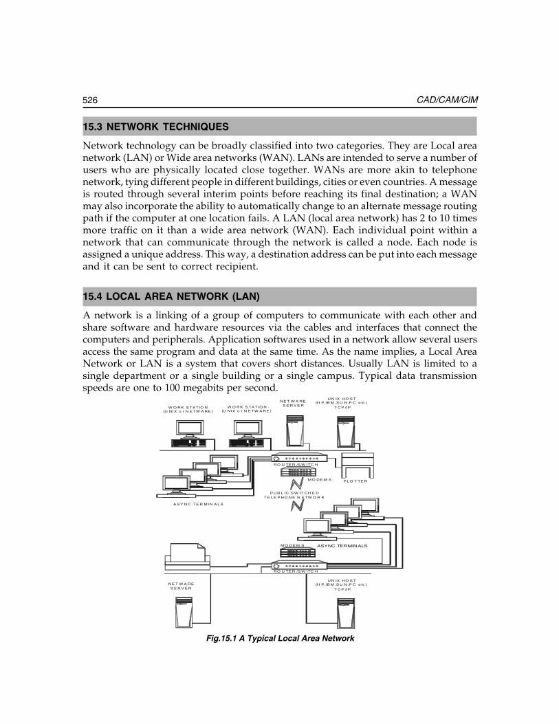
526 CAD/CAM/CIM
15.3 NETWORK TECHNIQUES
Network technology can be broadly classified into two categories. They are Local areanetwork (LAN) or Wide area networks (WAN). LANs are intended to serve a number ofusers who are physically located close together. WANs are more akin to telephonenetwork, tying different people in different buildings, cities or even countries. A messageis routed through several interim points before reaching its final destination; a WANmay also incorporate the ability to automatically change to an alternate message routingpath if the computer at one location fails. A LAN (local area network) has 2 to 10 timesmore traffic on it than a wide area network (WAN). Each individual point within anetwork that can communicate through the network is called a node. Each node isassigned a unique address. This way, a destination address can be put into each messageand it can be sent to correct recipient.
15.4 LOCAL AREA NETWORK (LAN)
A network is a linking of a group of computers to communicate with each other andshare software and hardware resources via the cables and interfaces that connect thecomputers and peripherals. Application softwares used in a network allow several usersaccess the same program and data at the same time. As the name implies, a Local AreaNetwork or LAN is a system that covers short distances. Usually LAN is limited to asingle department or a single building or a single campus. Typical data transmissionspeeds are one to 100 megabits per second.
W O RK S TA TIO N(U NIX o r N E TW A RE )
UN IX HO S T(H P,IB M ,S U N,P C e tc )
T CP /IP
UN IX HO S T(H P,IB M ,S U N,P C e tc )
T CP /IP
NE T W A RES E R V E R
NE T W A RES E R V E R
P UB L IC S W IT CH E DT E LE P HO N E N E TW O R K
A S Y NC .TE R M IN A LS
ASYNC.TERMINALS
W O RK S TA TIO N(U NIX o r N E TW A RE )
RO U TE R /S W ITC H
M O DE M S P LO T TE R
RO U TE R /S W ITC H
M O DE M S
Fig.15.1 A Typical Local Area Network
Ch
ap
ter
15C
ha
pte
r 15
Ch
ap
ter
15C
ha
pte
r 15
Ch
ap
ter
15
527Fundamentals of Networking
Fig. 15.1 shows a typical network, in which two LAN’s are shown, each networkinga number of computers connected to its file server. A network connects together a numberof workstations, as shown in the figure. Another way of interconnection is through a routerto which a number of asynchronous terminals are connected. Remote access to anotherLAN can be affected through a Router-Modem-Public Switched Telephone Network-Modem-Router scheme. A router is intermediate equipment, which transfers data betweentwo networks that use the same protocols. Modem is an equipment that connects acomputer to a telephone line (usually voice grade). Modems also connect a large localnetwork to a network provider over a leased line which is a dedicated communicationline leased from the Department of Telecommunications (DOT) by one or more userorganizations. Leased lines provide faster communication capability than dial-up lines.Common resources of the network include a bank of printers and plotters and facilitiesfor disc mirroring and disc duplexing.
Local area networks (LANs) fall into different sizes. Their topology, access method,medium, and market are different throughout. It is a private data communications systemcovering a limited geographical area, which is typically about a kilometre long. A LANlets a factory network communicate with computers vertically and horizontally. It allowssharing of input and output devices and databases. The LAN allows access to remotemainframes. Many LAN topologies are available today.
A LAN is capable of data transfer rates of 1-10 Mbits/sec in computer-to-computercommunications. It also handles requirements of dissimilar devices found in variousapplications, involving human, machines, and databases. A LAN can integrate the hardwareand data on shop floor. An advantage of a LAN is that it allows electronic communicationsto maintain, optimize, and use external database resources and process controls with lessthan 10 seconds response. It does appropriate filtering of messages so that bad messagescannot get through, and it allows downloading of program and data into productionequipment like programmable controllers, numerical controllers, and microprocessors tofacilitate flexible manufacturing. LANs allow machines and managers and supervisors tomonitor the entire process by “zooming” onto any particular segment in as great detail asnecessary. The LAN can monitor quality and make corrections, or, stop process to allowhumans to make corrections, before the quality or yield of system goes down belowacceptable levels.
A basic requirement of a LAN is that it must have a flexible architecture to permit PC’sand other computers located where they are needed. It must also be possible to remove acomputer without causing disruption. Reliability is another important aspect. Since themanufacturing activities depend upon the working of LAN, the LAN system must be highlyreliable. The most widely used LAN system is Ethernet.
PC’s attached to a LAN can use the processing capabilities of other intelligent devicesin the network as in a host-to-terminal network.
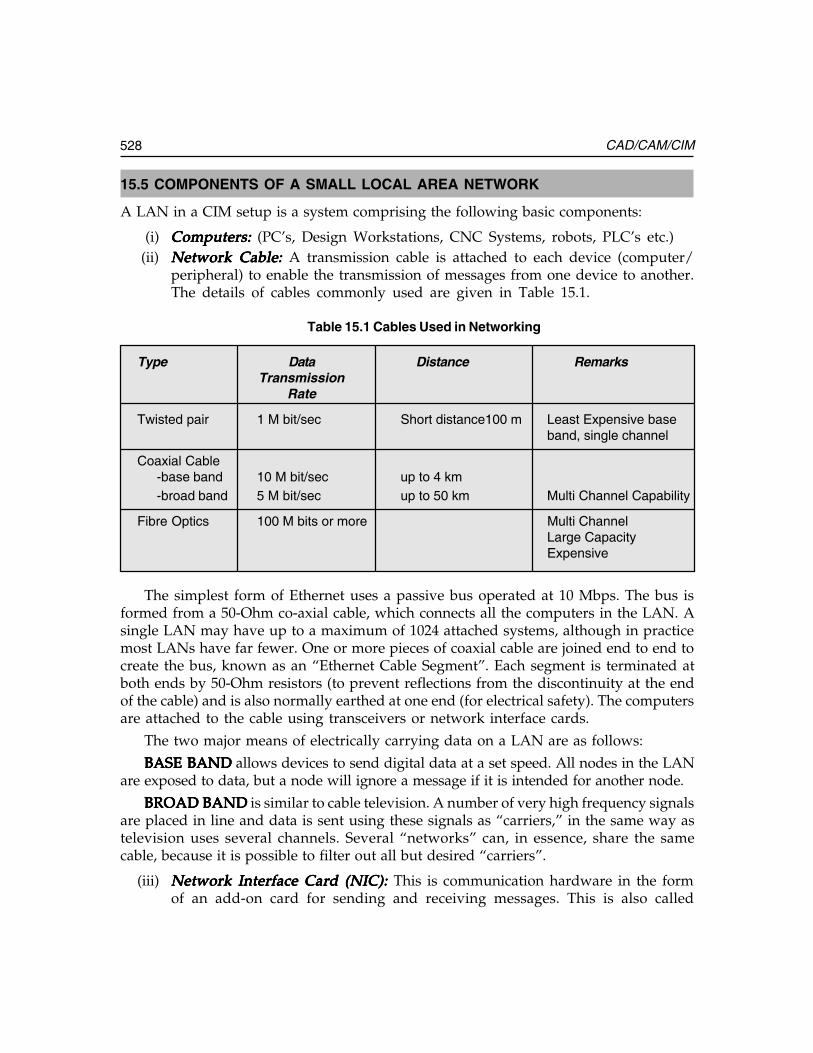
528 CAD/CAM/CIM
15.5 COMPONENTS OF A SMALL LOCAL AREA NETWORK
A LAN in a CIM setup is a system comprising the following basic components:
(i) Computers:Computers:Computers:Computers:Computers: (PC’s, Design Workstations, CNC Systems, robots, PLC’s etc.)(ii) Network Cable:Network Cable:Network Cable:Network Cable:Network Cable: A transmission cable is attached to each device (computer/
peripheral) to enable the transmission of messages from one device to another.The details of cables commonly used are given in Table 15.1.
Table 15.1 Cables Used in Networking
Type Data Distance RemarksTransmission
Rate
Twisted pair 1 M bit/sec Short distance100 m Least Expensive baseband, single channel
Coaxial Cable-base band 10 M bit/sec up to 4 km-broad band 5 M bit/sec up to 50 km Multi Channel Capability
Fibre Optics 100 M bits or more Multi ChannelLarge CapacityExpensive
The simplest form of Ethernet uses a passive bus operated at 10 Mbps. The bus isformed from a 50-Ohm co-axial cable, which connects all the computers in the LAN. Asingle LAN may have up to a maximum of 1024 attached systems, although in practicemost LANs have far fewer. One or more pieces of coaxial cable are joined end to end tocreate the bus, known as an “Ethernet Cable Segment”. Each segment is terminated atboth ends by 50-Ohm resistors (to prevent reflections from the discontinuity at the endof the cable) and is also normally earthed at one end (for electrical safety). The computersare attached to the cable using transceivers or network interface cards.
The two major means of electrically carrying data on a LAN are as follows:
BASE BANDBASE BANDBASE BANDBASE BANDBASE BAND allows devices to send digital data at a set speed. All nodes in the LANare exposed to data, but a node will ignore a message if it is intended for another node.
BROAD BANDBROAD BANDBROAD BANDBROAD BANDBROAD BAND is similar to cable television. A number of very high frequency signalsare placed in line and data is sent using these signals as “carriers,” in the same way astelevision uses several channels. Several “networks” can, in essence, share the samecable, because it is possible to filter out all but desired “carriers”.
(iii) Network Interface Card (NIC): Network Interface Card (NIC): Network Interface Card (NIC): Network Interface Card (NIC): Network Interface Card (NIC): This is communication hardware in the formof an add-on card for sending and receiving messages. This is also called
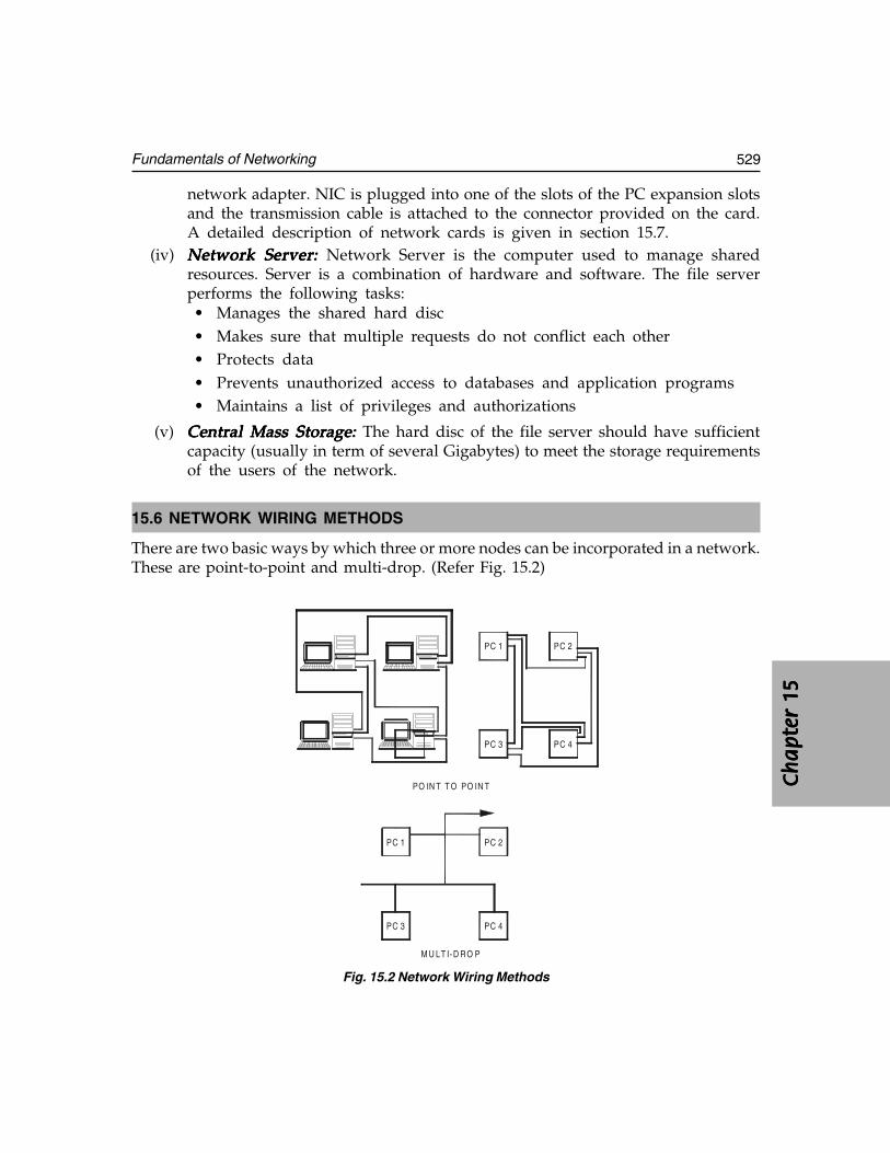
Ch
ap
ter
15C
ha
pte
r 15
Ch
ap
ter
15C
ha
pte
r 15
Ch
ap
ter
15
529Fundamentals of Networking
network adapter. NIC is plugged into one of the slots of the PC expansion slotsand the transmission cable is attached to the connector provided on the card.A detailed description of network cards is given in section 15.7.
(iv) Network Server:Network Server:Network Server:Network Server:Network Server: Network Server is the computer used to manage sharedresources. Server is a combination of hardware and software. The file serverperforms the following tasks:• Manages the shared hard disc• Makes sure that multiple requests do not conflict each other• Protects data• Prevents unauthorized access to databases and application programs• Maintains a list of privileges and authorizations
(v) Central Mass Storage:Central Mass Storage:Central Mass Storage:Central Mass Storage:Central Mass Storage: The hard disc of the file server should have sufficientcapacity (usually in term of several Gigabytes) to meet the storage requirementsof the users of the network.
15.6 NETWORK WIRING METHODS
There are two basic ways by which three or more nodes can be incorporated in a network.These are point-to-point and multi-drop. (Refer Fig. 15.2)
PC 1 PC 2
PC 3 PC 4
PC 1 PC 2
PC 3 PC 4
PO IN T T O PO IN T
M U LT I-D R O P
Fig. 15.2 Network Wiring Methods
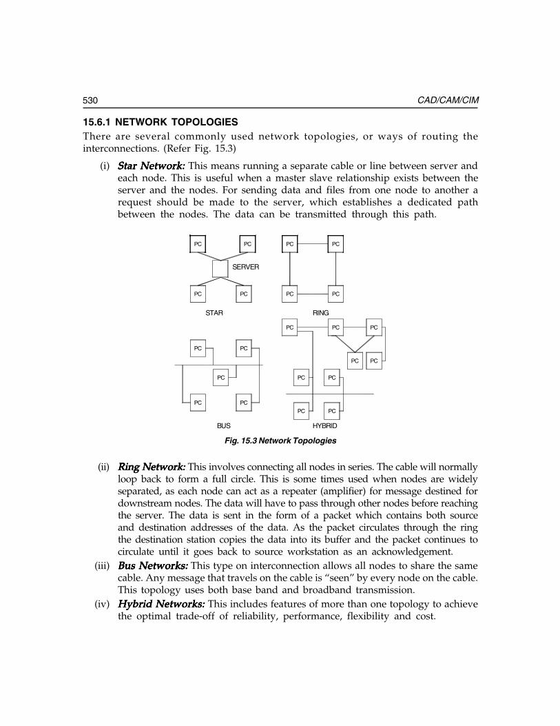
530 CAD/CAM/CIM
15.6.1 NETWORK TOPOLOGIESThere are several commonly used network topologies, or ways of routing theinterconnections. (Refer Fig. 15.3)
(i) Star Network: Star Network: Star Network: Star Network: Star Network: This means running a separate cable or line between server andeach node. This is useful when a master slave relationship exists between theserver and the nodes. For sending data and files from one node to another arequest should be made to the server, which establishes a dedicated pathbetween the nodes. The data can be transmitted through this path.
PC PC PC PC
PC PC PC PC
PC PC
PC PC PC
PC PC
PC
PC PC
PC PC
PC PC
STAR RING
BUS HYBRID
SERVER
Fig. 15.3 Network Topologies
(ii) Ring Network: Ring Network: Ring Network: Ring Network: Ring Network: This involves connecting all nodes in series. The cable will normallyloop back to form a full circle. This is some times used when nodes are widelyseparated, as each node can act as a repeater (amplifier) for message destined fordownstream nodes. The data will have to pass through other nodes before reachingthe server. The data is sent in the form of a packet which contains both sourceand destination addresses of the data. As the packet circulates through the ringthe destination station copies the data into its buffer and the packet continues tocirculate until it goes back to source workstation as an acknowledgement.
(iii) Bus Networks:Bus Networks:Bus Networks:Bus Networks:Bus Networks: This type on interconnection allows all nodes to share the samecable. Any message that travels on the cable is “seen” by every node on the cable.This topology uses both base band and broadband transmission.
(iv) Hybrid Networks:Hybrid Networks:Hybrid Networks:Hybrid Networks:Hybrid Networks: This includes features of more than one topology to achievethe optimal trade-off of reliability, performance, flexibility and cost.
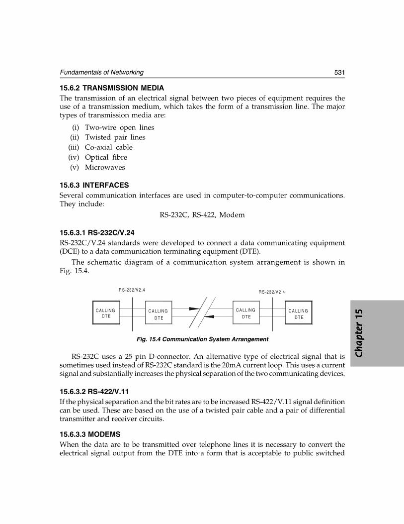
Ch
ap
ter
15C
ha
pte
r 15
Ch
ap
ter
15C
ha
pte
r 15
Ch
ap
ter
15
531Fundamentals of Networking
15.6.2 TRANSMISSION MEDIAThe transmission of an electrical signal between two pieces of equipment requires theuse of a transmission medium, which takes the form of a transmission line. The majortypes of transmission media are:
(i) Two-wire open lines(ii) Twisted pair lines
(iii) Co-axial cable(iv) Optical fibre(v) Microwaves
15.6.3 INTERFACESSeveral communication interfaces are used in computer-to-computer communications.They include:
RS-232C, RS-422, Modem
15.6.3.1 RS-232C/V.24RS-232C/V.24 standards were developed to connect a data communicating equipment(DCE) to a data communication terminating equipment (DTE).
The schematic diagram of a communication system arrangement is shown inFig. 15.4.
C A LLIN GD TE
C A LLIN G
D TE
C A LLIN G
D T EC A LLIN G
D T E
R S -23 2/V2 .4 R S -23 2/V2 .4
Fig. 15.4 Communication System Arrangement
RS-232C uses a 25 pin D-connector. An alternative type of electrical signal that issometimes used instead of RS-232C standard is the 20mA current loop. This uses a currentsignal and substantially increases the physical separation of the two communicating devices.
15.6.3.2 RS-422/V.11If the physical separation and the bit rates are to be increased RS-422/V.11 signal definitioncan be used. These are based on the use of a twisted pair cable and a pair of differentialtransmitter and receiver circuits.
15.6.3.3 MODEMSWhen the data are to be transmitted over telephone lines it is necessary to convert theelectrical signal output from the DTE into a form that is acceptable to public switched
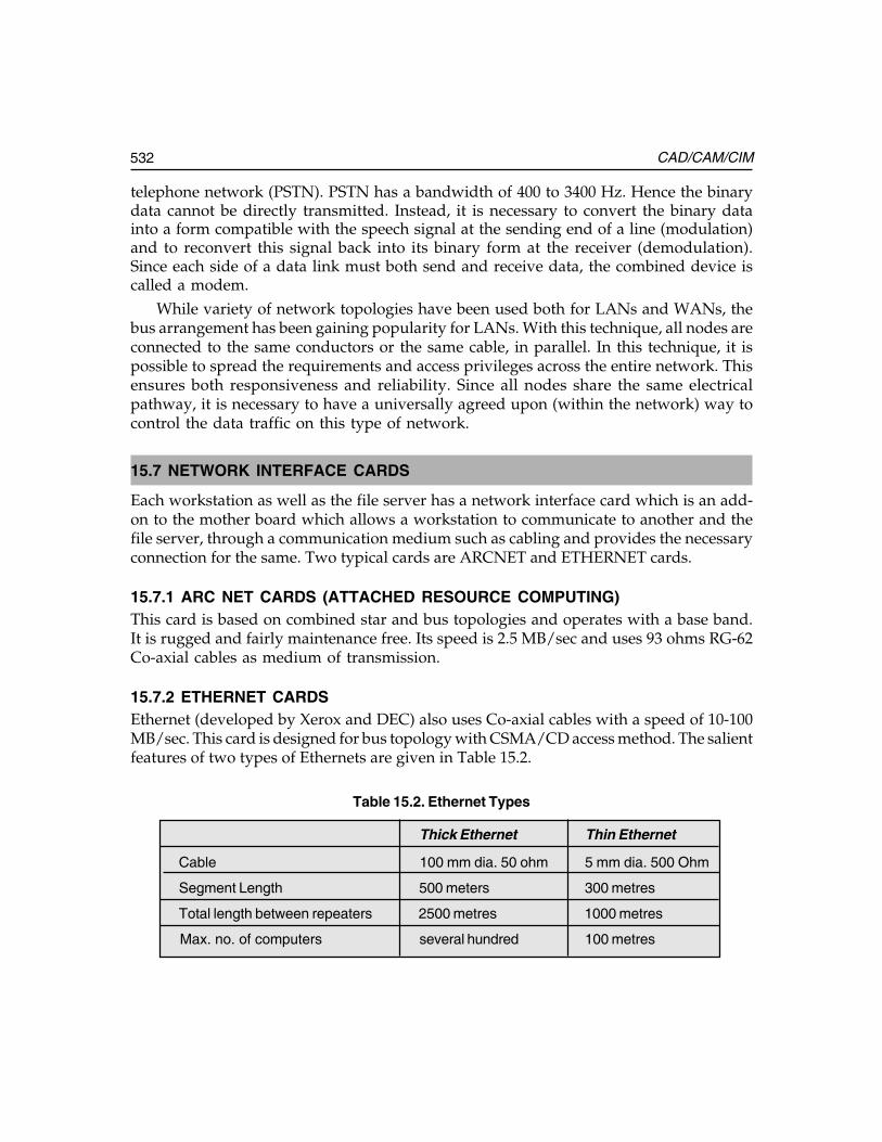
532 CAD/CAM/CIM
telephone network (PSTN). PSTN has a bandwidth of 400 to 3400 Hz. Hence the binarydata cannot be directly transmitted. Instead, it is necessary to convert the binary datainto a form compatible with the speech signal at the sending end of a line (modulation)and to reconvert this signal back into its binary form at the receiver (demodulation).Since each side of a data link must both send and receive data, the combined device iscalled a modem.
While variety of network topologies have been used both for LANs and WANs, thebus arrangement has been gaining popularity for LANs. With this technique, all nodes areconnected to the same conductors or the same cable, in parallel. In this technique, it ispossible to spread the requirements and access privileges across the entire network. Thisensures both responsiveness and reliability. Since all nodes share the same electricalpathway, it is necessary to have a universally agreed upon (within the network) way tocontrol the data traffic on this type of network.
15.7 NETWORK INTERFACE CARDS
Each workstation as well as the file server has a network interface card which is an add-on to the mother board which allows a workstation to communicate to another and thefile server, through a communication medium such as cabling and provides the necessaryconnection for the same. Two typical cards are ARCNET and ETHERNET cards.
15.7.1 ARC NET CARDS (ATTACHED RESOURCE COMPUTING)This card is based on combined star and bus topologies and operates with a base band.It is rugged and fairly maintenance free. Its speed is 2.5 MB/sec and uses 93 ohms RG-62Co-axial cables as medium of transmission.
15.7.2 ETHERNET CARDSEthernet (developed by Xerox and DEC) also uses Co-axial cables with a speed of 10-100MB/sec. This card is designed for bus topology with CSMA/CD access method. The salientfeatures of two types of Ethernets are given in Table 15.2.
Table 15.2. Ethernet Types
Thick Ethernet Thin Ethernet
Cable 100 mm dia. 50 ohm 5 mm dia. 500 Ohm
Segment Length 500 meters 300 metres
Total length between repeaters 2500 metres 1000 metres
Max. no. of computers several hundred 100 metres
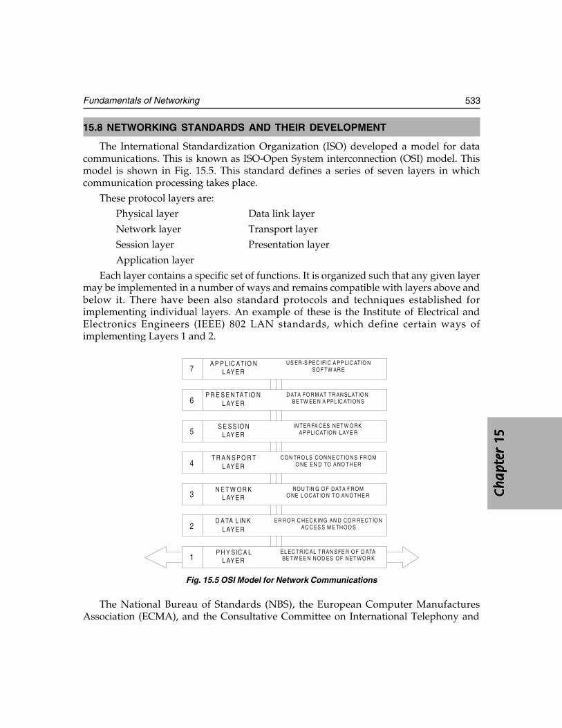
Ch
ap
ter
15C
ha
pte
r 15
Ch
ap
ter
15C
ha
pte
r 15
Ch
ap
ter
15
533Fundamentals of Networking
15.8 NETWORKING STANDARDS AND THEIR DEVELOPMENT
The International Standardization Organization (ISO) developed a model for datacommunications. This is known as ISO-Open System interconnection (OSI) model. Thismodel is shown in Fig. 15.5. This standard defines a series of seven layers in whichcommunication processing takes place.
These protocol layers are:
Physical layer Data link layer
Network layer Transport layer
Session layer Presentation layer
Application layer
Each layer contains a specific set of functions. It is organized such that any given layermay be implemented in a number of ways and remains compatible with layers above andbelow it. There have been also standard protocols and techniques established forimplementing individual layers. An example of these is the Institute of Electrical andElectronics Engineers (IEEE) 802 LAN standards, which define certain ways ofimplementing Layers 1 and 2.
A P P L IC A TIO NL AY E R
P R E S E N TA T IO NL AY E R
S E S S IO NL AY E R
T R A N S P O R TL AY E R
N E T W O R KL AY E R
D A TA L IN KL AY E R
P H Y S IC A LL AY E R
U S ER -S PEC IFIC A PP LIC ATIO NSO F TW AR E
D ATA FO R M AT TR AN SL AT IO NBE TW EE N A PPL IC ATION S
IN TER FA C ES N ET W OR K AP PL IC AT ION LAYE R
C ON TR O LS C ON N E C T ION S FR OMO NE EN D TO A NO T H ER
R OU TIN G O F D ATA F R OMO NE L OC AT IO N T O AN O TH E R
ER R OR C H EC K IN G AN D CO R RE CT IO NAC C ES S M E TH O D S
EL EC TR IC AL T R AN S FE R O F D ATABE TW EE N N OD ES OF N ET W O R K
7
6
5
4
3
2
1
Fig. 15.5 OSI Model for Network Communications
The National Bureau of Standards (NBS), the European Computer ManufacturesAssociation (ECMA), and the Consultative Committee on International Telephony and
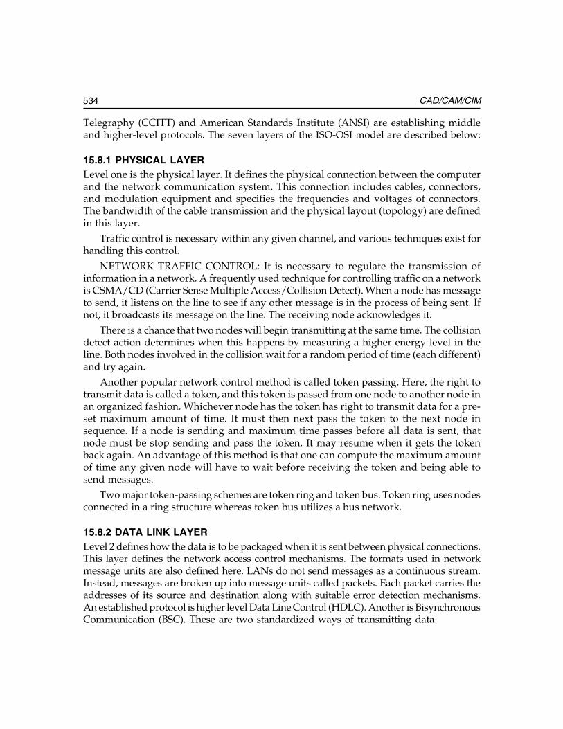
534 CAD/CAM/CIM
Telegraphy (CCITT) and American Standards Institute (ANSI) are establishing middleand higher-level protocols. The seven layers of the ISO-OSI model are described below:
15.8.1 PHYSICAL LAYERLevel one is the physical layer. It defines the physical connection between the computerand the network communication system. This connection includes cables, connectors,and modulation equipment and specifies the frequencies and voltages of connectors.The bandwidth of the cable transmission and the physical layout (topology) are definedin this layer.
Traffic control is necessary within any given channel, and various techniques exist forhandling this control.
NETWORK TRAFFIC CONTROL: It is necessary to regulate the transmission ofinformation in a network. A frequently used technique for controlling traffic on a networkis CSMA/CD (Carrier Sense Multiple Access/Collision Detect). When a node has messageto send, it listens on the line to see if any other message is in the process of being sent. Ifnot, it broadcasts its message on the line. The receiving node acknowledges it.
There is a chance that two nodes will begin transmitting at the same time. The collisiondetect action determines when this happens by measuring a higher energy level in theline. Both nodes involved in the collision wait for a random period of time (each different)and try again.
Another popular network control method is called token passing. Here, the right totransmit data is called a token, and this token is passed from one node to another node inan organized fashion. Whichever node has the token has right to transmit data for a pre-set maximum amount of time. It must then next pass the token to the next node insequence. If a node is sending and maximum time passes before all data is sent, thatnode must be stop sending and pass the token. It may resume when it gets the tokenback again. An advantage of this method is that one can compute the maximum amountof time any given node will have to wait before receiving the token and being able tosend messages.
Two major token-passing schemes are token ring and token bus. Token ring uses nodesconnected in a ring structure whereas token bus utilizes a bus network.
15.8.2 DATA LINK LAYERLevel 2 defines how the data is to be packaged when it is sent between physical connections.This layer defines the network access control mechanisms. The formats used in networkmessage units are also defined here. LANs do not send messages as a continuous stream.Instead, messages are broken up into message units called packets. Each packet carries theaddresses of its source and destination along with suitable error detection mechanisms.An established protocol is higher level Data Line Control (HDLC). Another is BisynchronousCommunication (BSC). These are two standardized ways of transmitting data.
Ch
ap
ter
15C
ha
pte
r 15
Ch
ap
ter
15C
ha
pte
r 15
Ch
ap
ter
15
535Fundamentals of Networking
15.8.3 NETWORK LAYERThis layer defines switching and routing information between networks and how packetsof data are exchanged between different LANs. An example is the X.25 standard, whichdefines standards for packet switching networks.
15.8.4 TRANSPORT LAYERThe transport layer defines network addressing and the way in which connectionsbetween networks can be linked or unlinked. The transport layer guarantees the messagedelivery with no omissions or duplications.
15.8.5 SESSION LAYERThe primary function of this layer is to define an application interface to the transportlayer. This layer maps names to network addresses so that applications can use names tocommunicate with devices.
Layers 3, 4 and 5 combine to form a sub-net level containing the software, which controlsthe network hardware. Though cables are attached to every device in a network, actualcommunication involves only two devices—the sender and the receiver. The subnet levelestablishes and manages a temporary link called virtual connection between the senderand the receiver.
At levels 4 and 5, the major concern is about how applications in different LANscommunicate. Consider two computers on a LAN, each running different programs. (SeeFig. 15.6.) Program A on computer 1 needs to exchange data with program C on computer2; program B on computer one needs to talk with program D on computer 2. Level 4 ofOSI establishes virtual channels, effectively isolating each pair of communicating programsfrom other sets of programs talking over the network.
PROGRAM A
LAYER 7
PROGRAM B
LAYER 7
LAYER 6
LAYER 6
LAYER 1
PROGRAM B
LAYER 7 LAYER 1
LAYER 6
PROGRAM A
LAYER 7 LAYER 6
PROGRAM ADATA
PROGRAM BDATA
PROGRAM CDATA
PROGRAM DDATA
COMPUTER 1
COMPUTER 2
Fig. 15.6 Communication between Different Applications
536 CAD/CAM/CIM
15.8.6 PRESENTATION LAYERThis layer defines the translation formats and syntax from an application to the networkand the manner in which software applications enter the network.
15.8.7 APPLICATION LAYERThis layer contains several programs that define the network applications that supportfile serving.
The developments in computer communication during the last two years havesignificantly simplified the communication protocols.
15.9 EXAMPLES OF NETWORK STANDARDS
Several computer manufacturers and organizations have developed systems for networkcommunications.
15.9.1 DECNETDECNET is a trademark of former Digital Equipment Corporation. This is a good exampleof a network following Level 2 through 8 of the ISO OSI standard. DECNET allows changeof files between computers. It allows a terminal attached to computer A to interact withcomputer B in another location. In advanced applications, it even supports distributeddatabases. It is a software protocol, where a number of different electrical and line protocolsmay be used to support it. For example DECNET is used in a hybrid, point-to-point network.It may also use Ethernet as an electrical protocol.
15.9.2 SYSTEM NETWORK ARCHITECTUREIBM’s System Network Architecture (SNA) is a network management scheme usedprimarily for peer-to-peer communications between computers. It has become a de-factostandard for interconnection of large mainframes, due to popularity of IBM and IBMcompatible hardware. Gateway devices are available from several manufacturers tointerface between SNA and various LANs. SNA to non-IBM computer interfaces are alsoavailable. Several other vendors also supply SNA interfaces.
15.9.3 MANUFACTURING AUTOMATION PROTOCOL (MAP)MAP is a hardware/software protocol developed jointly by a group of industries andvendors of computers and PLCs. It follows the ISO OSI model. MAP was developed as aresult of the plans of General Motors to automate its factories.
MAP uses a broad band LAN, with a token ring protocol for traffic control. Since it isbroadband, all devices in the LAN like computers, CNC machines, robots, and PLC’s etc.share the same cable, but different groups of devices can be placed on separate “channels”on the line. Additionally, closed circuit TV (video) channel can also be accommodatedon same cable. MAP physical level is based on the IEEE 802.4 token-bus standard. At the
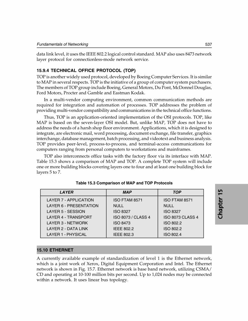
Ch
ap
ter
15C
ha
pte
r 15
Ch
ap
ter
15C
ha
pte
r 15
Ch
ap
ter
15
537Fundamentals of Networking
data link level, it uses the IEEE 802.2 logical control standard. MAP also uses 8473 networklayer protocol for connectionless-mode network service.
15.9.4 TECHNICAL OFFICE PROTOCOL (TOP)TOP is another widely used protocol, developed by Boeing Computer Services. It is similarto MAP in several respects. TOP is the initiative of a group of computer system purchasers.The members of TOP group include Boeing, General Motors, Du Pont, McDonnel Douglas,Ford Motors, Procter and Gamble and Eastman Kodak.
In a multi-vendor computing environment, common communication methods arerequired for integration and automation of processes. TOP addresses the problem ofproviding multi-vendor compatibility and communications in the technical office functions.
Thus, TOP is an application-oriented implementation of the OSI protocols. TOP, likeMAP is based on the seven-layer OSI model. But, unlike MAP, TOP does not have toaddress the needs of a harsh shop floor environment. Applications, which it is designed tointegrate, are electronic mail, word processing, document exchange, file transfer, graphicsinterchange, database management, batch processing, and videotext and business analysis.TOP provides peer-level, process-to-process, and terminal-access communications forcomputers ranging from personal computers to workstations and mainframes.
TOP also interconnects office tasks with the factory floor via its interface with MAP.Table 15.3 shows a comparison of MAP and TOP. A complete TOP system will includeone or more building blocks covering layers one to four and at least one building block forlayers 5 to 7.
Table 15.3 Comparison of MAP and TOP Protocols
LAYER MAP TOP
LAYER 7 - APPLICATION ISO FTAM 8571 ISO FTAM 8571LAYER 6 - PRESENTATION NULL NULLLAYER 5 - SESSION ISO 8327 ISO 8327LAYER 4 - TRANSPORT ISO 8073 / CLASS 4 ISO 8073 CLASS 4LAYER 3 - NETWORK ISO 8473 ISO 802.2LAYER 2 - DATA LINK IEEE 802.2 ISO 802.2LAYER 1 - PHYSICAL IEEE 802.3 ISO 802.4
15.10 ETHERNET
A currently available example of standardization of level 1 is the Ethernet network,which is a joint work of Xerox, Digital Equipment Corporation and Intel. The Ethernetnetwork is shown in Fig. 15.7. Ethernet network is base band network, utilizing CSMA/CD and operating at 10-100 million bits per second. Up to 1,024 nodes may be connectedwithin a network. It uses linear bus topology.
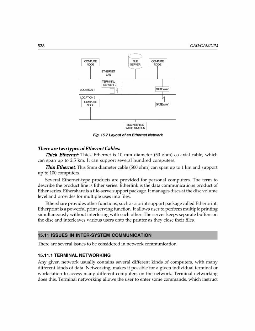
538 CAD/CAM/CIM
COMPUTENODE
ETHERNETLAN
FILESERVER
COMPUTENODE
TERMINALSERVER
GATEWAY
GATEWAY
ENGINEERINGWORK STATION
COMPUTENODE
LOCATION 1
LOCATION 2
Fig. 15.7 Layout of an Ethernet Network
There are two types of Ethernet Cables:There are two types of Ethernet Cables:There are two types of Ethernet Cables:There are two types of Ethernet Cables:There are two types of Ethernet Cables:Thick EthernetThick EthernetThick EthernetThick EthernetThick Ethernet: Thick Ethernet is 10 mm diameter (50 ohm) co-axial cable, which
can span up to 2.5 km. It can support several hundred computers.
Thin EthernetThin EthernetThin EthernetThin EthernetThin Ethernet: This 5mm diameter cable (500 ohm) can span up to 1 km and supportup to 100 computers.
Several Ethernet-type products are provided for personal computers. The term todescribe the product line is Ether series. Etherlink is the data communications product ofEther series. Ethershare is a file-serve support package. It manages discs at the disc volumelevel and provides for multiple uses into files.
Ethershare provides other functions, such as a print support package called Etherprint.Etherprint is a powerful print serving function. It allows user to perform multiple printingsimultaneously without interfering with each other. The server keeps separate buffers onthe disc and interleaves various users onto the printer as they close their files.
15.11 ISSUES IN INTER-SYSTEM COMMUNICATION
There are several issues to be considered in network communication.
15.11.1 TERMINAL NETWORKINGAny given network usually contains several different kinds of computers, with manydifferent kinds of data. Networking, makes it possible for a given individual terminal orworkstation to access many different computers on the network. Terminal networkingdoes this. Terminal networking allows the user to enter some commands, which instruct
Ch
ap
ter
15C
ha
pte
r 15
Ch
ap
ter
15C
ha
pte
r 15
Ch
ap
ter
15
539Fundamentals of Networking
the appropriate network device to establish communication between the user’s terminaland the desired computer. A lot of flexibility is provided by this arrangement. For example,any given node can be more specialized and optimized to its task-yet locally attachedusers are not confined to narrow range of capabilities, but rather can have access to the fullrange of functionality afforded by the network. With this flexibility comes a requirementfor great care in system operation.
15.11.2 FILE SHARINGWhen it is necessary to share and/or transfer files across a network from one networknode to another file sharing is used. The steps involved in file sharing are:
(i) Understand and service file requests coming from any where in the network.(ii) Realize when the user needs to access a file which is stored at another network
node, then request the file from the INPUT/OUTPUT driver on the other system,via the network.
From the stand point of a given network node, this technique can be used to access andread a file from another node, and also send a file to another node.
15.11.3 DATA TRANSLATIONPhysical capability of exchanging data between two computers does not automaticallyguarantee that the programs on one computer will be able to decipher data stored on theother. The data on one system may be stored in a format, which is unintelligible to programson the other system. Because of this, it is important to consider the requirements andtechniques for data translation networks. This is especially critical when you plan to mixhardware and/or software from different vendors in a network.
15.11.4 DISTRIBUTED DATABASEAn input/output driver can also be designed to read or write individual records within afile across the network. In the case of a structured file system like a relational, hierarchicalor network database remote access requires many issues to be dealt with.
The design of database structure is affected by network topology. Specifically, thismeans that you can place a given type of data on the individual computer that uses it most.For example, consider a distributed database of a manufacturing company, which includesproduction statistics from its foundry department. The data can reside directly on thefoundry’s computer and nowhere else.
Later, when a program running on the plant computer is doing a summary of totalfactory production and needs the data on the foundry computer, the plant computer accessesthese records directly. The plant computer may also write some records into the foundry’sproduction plan database indicating new production requirements.
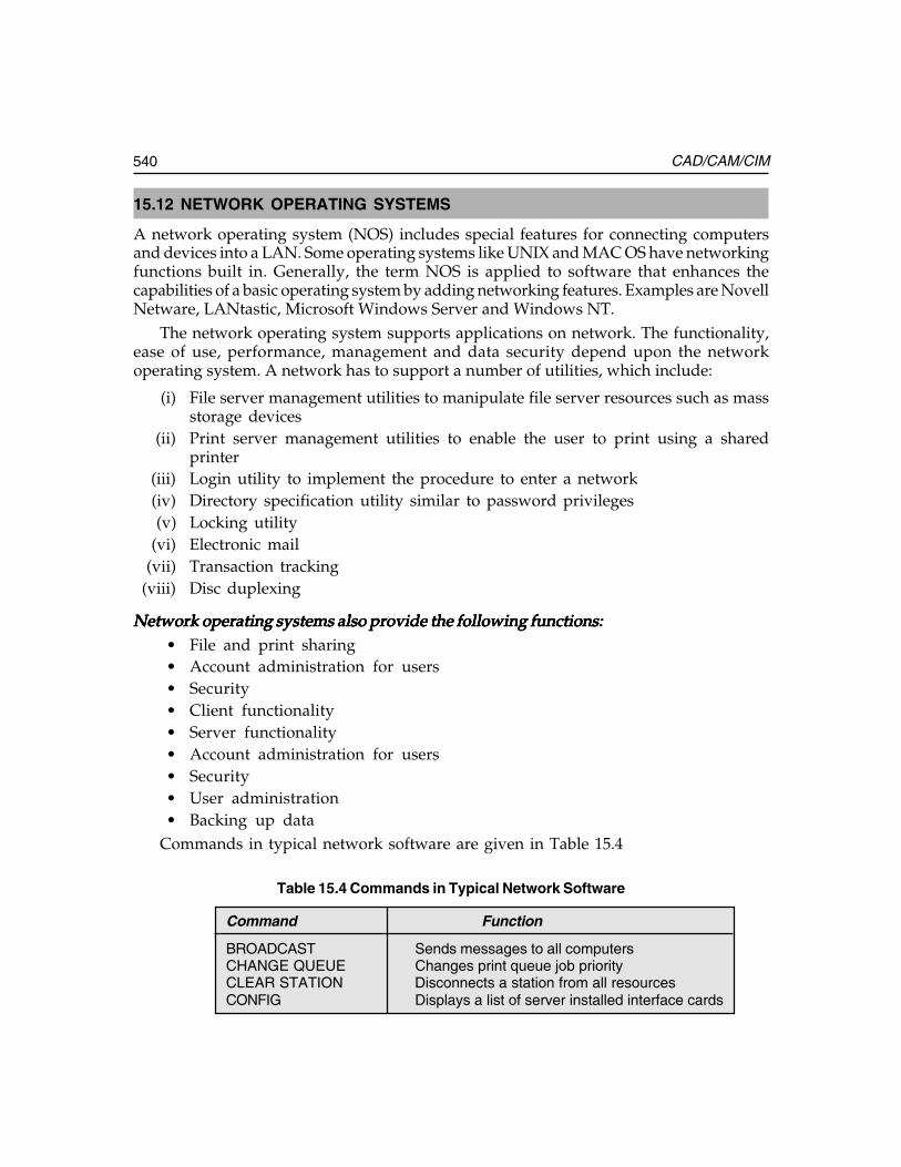
540 CAD/CAM/CIM
15.12 NETWORK OPERATING SYSTEMS
A network operating system (NOS) includes special features for connecting computersand devices into a LAN. Some operating systems like UNIX and MAC OS have networkingfunctions built in. Generally, the term NOS is applied to software that enhances thecapabilities of a basic operating system by adding networking features. Examples are NovellNetware, LANtastic, Microsoft Windows Server and Windows NT.
The network operating system supports applications on network. The functionality,ease of use, performance, management and data security depend upon the networkoperating system. A network has to support a number of utilities, which include:
(i) File server management utilities to manipulate file server resources such as massstorage devices
(ii) Print server management utilities to enable the user to print using a sharedprinter
(iii) Login utility to implement the procedure to enter a network(iv) Directory specification utility similar to password privileges(v) Locking utility
(vi) Electronic mail(vii) Transaction tracking
(viii) Disc duplexing
Network operating systems also provide the following functions:Network operating systems also provide the following functions:Network operating systems also provide the following functions:Network operating systems also provide the following functions:Network operating systems also provide the following functions:• File and print sharing• Account administration for users• Security• Client functionality• Server functionality• Account administration for users• Security• User administration• Backing up data
Commands in typical network software are given in Table 15.4
Table 15.4 Commands in Typical Network Software
Command Function
BROADCAST Sends messages to all computersCHANGE QUEUE Changes print queue job priorityCLEAR STATION Disconnects a station from all resourcesCONFIG Displays a list of server installed interface cards
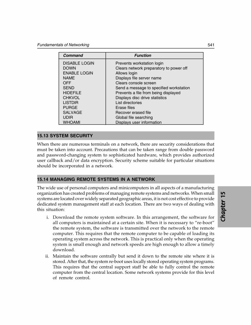
Ch
ap
ter
15C
ha
pte
r 15
Ch
ap
ter
15C
ha
pte
r 15
Ch
ap
ter
15
541Fundamentals of Networking
Command Function
DISABLE LOGIN Prevents workstation loginDOWN Clears network preparatory to power offENABLE LOGIN Allows loginNAME Displays file server nameOFF Clears console screenSEND Send a message to specified workstationHIDEFILE Prevents a file from being displayedCHKVOL Displays disc drive statisticsLISTDIR List directoriesPURGE Erase filesSALVAGE Recover erased fileUDIR Global file searchingWHOAMI Displays user information
15.13 SYSTEM SECURITY
When there are numerous terminals on a network, there are security considerations thatmust be taken into account. Precautions that can be taken range from double passwordand password-changing system to sophisticated hardware, which provides authorizeduser callback and/or data encryption. Security scheme suitable for particular situationsshould be incorporated in a network.
15.14 MANAGING REMOTE SYSTEMS IN A NETWORK
The wide use of personal computers and minicomputers in all aspects of a manufacturingorganization has created problems of managing remote systems and networks. When smallsystems are located over widely separated geographic areas, it is not cost effective to providededicated system management staff at each location. There are two ways of dealing withthis situation:
i. Download the remote system software. In this arrangement, the software forall computers is maintained at a certain site. When it is necessary to “re-boot”the remote system, the software is transmitted over the network to the remotecomputer. This requires that the remote computer to be capable of loading itsoperating system across the network. This is practical only when the operatingsystem is small enough and network speeds are high enough to allow a timelydownload.
ii. Maintain the software centrally but send it down to the remote site where it isstored. After that, the system re-boot uses locally stored operating system programs.This requires that the central support staff be able to fully control the remotecomputer from the central location. Some network systems provide for this levelof remote control.
542 CAD/CAM/CIM
15.15 DESIGN ACTIVITY IN A NETWORKED ENVIRONMENT
Several large-scale design activities require several engineers (sometimes even hundreds)to work on different aspects of design; Examples are design of aircrafts and VLSI andUVLSI chip designs. Such designs are efficiently carried out in a networked environment.
In a network linking several CAD systems, a situation may arise where designers atseveral different locations need to access the same design data. Design control, in its simplestform, ensures that two different designers never modify the same design independently.Unless this situation is somehow controlled, design can be lost, because the second designerto save his change will wipe out the work done on that design by the first designer.
What is required here is a system, which allows an authorized designer to check out adesign. While the design is being modified, a copy of the original design is retained by thesystem, but nobody else can work on that design. The system must also maintain the identityof the designer who has checked it out. This type of system is especially important on anetwork, where many users can potentially and inadvertently conflict with each other.
15.16 ENGINEERING CHANGE CONTROL
Engineering changes frequently occur and should be communicated to all the personnelconcerned. A network almost necessarily implies a large organization, or at least onescattered across a geographical area; otherwise, there would be no need for network.Therefore, a networked system is likely to have a need for automatic notification of variouspeople involved when an engineering change is effected. One of the requirements of CIMis the effective communication and networking helps a lot in this regard.
There are several milestones in an engineering change:
i. When ordered (and why and by whom)ii. When change is incorporated in design
iii. When change becomes effective for production
Because engineering changes can affect other aspects of manufacturing, companiesoften implement systems, which are driven by engineering changes. These systems performfunctions such as:
i. Automatic distribution of changed drawings to all areas requiring these.ii. Maintenance of history of changes for contract reasons. Effective engineering
change control will eliminate wastages and delays in a manufacturing organization.
15.17 NETWORKING IN A MANUFACTURING COMPANY
A manufacturing company carries out a number of operations using computers.
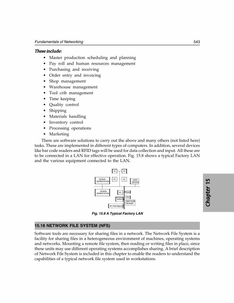
Ch
ap
ter
15C
ha
pte
r 15
Ch
ap
ter
15C
ha
pte
r 15
Ch
ap
ter
15
543Fundamentals of Networking
These include:These include:These include:These include:These include:
• Master production scheduling and planning• Pay roll and human resources management• Purchasing and receiving• Order entry and invoicing• Shop management• Warehouse management• Tool crib management• Time keeping• Quality control• Shipping• Materials handling• Inventory control• Processing operations• Marketing
There are software solutions to carry out the above and many others (not listed here)tasks. These are implemented in different types of computers. In addition, several deviceslike bar code readers and RFID tags will be used for data collection and input. All these areto be connected in a LAN for effective operation. Fig. 15.8 shows a typical Factory LANand the various equipment connected to the LAN.
DESIGNWORKSTATION
PC
ROBOT
CNC
PLC
RF PORTABLES
BAR CODEREADER
WORKSTATIONDESIGN
PC
PC PC
PC
HOSTSERVER
Fig. 15.8 A Typical Factory LAN
15.18 NETWORK FILE SYSTEM (NFS)
Software tools are necessary for sharing files in a network. The Network File System is afacility for sharing files in a heterogeneous environment of machines, operating systemsand networks. Mounting a remote file system, then reading or writing files in place, sincethese units may use different operating systems accomplishes sharing. A brief descriptionof Network File System is included in this chapter to enable the readers to understand thecapabilities of a typical network file system used in workstations.
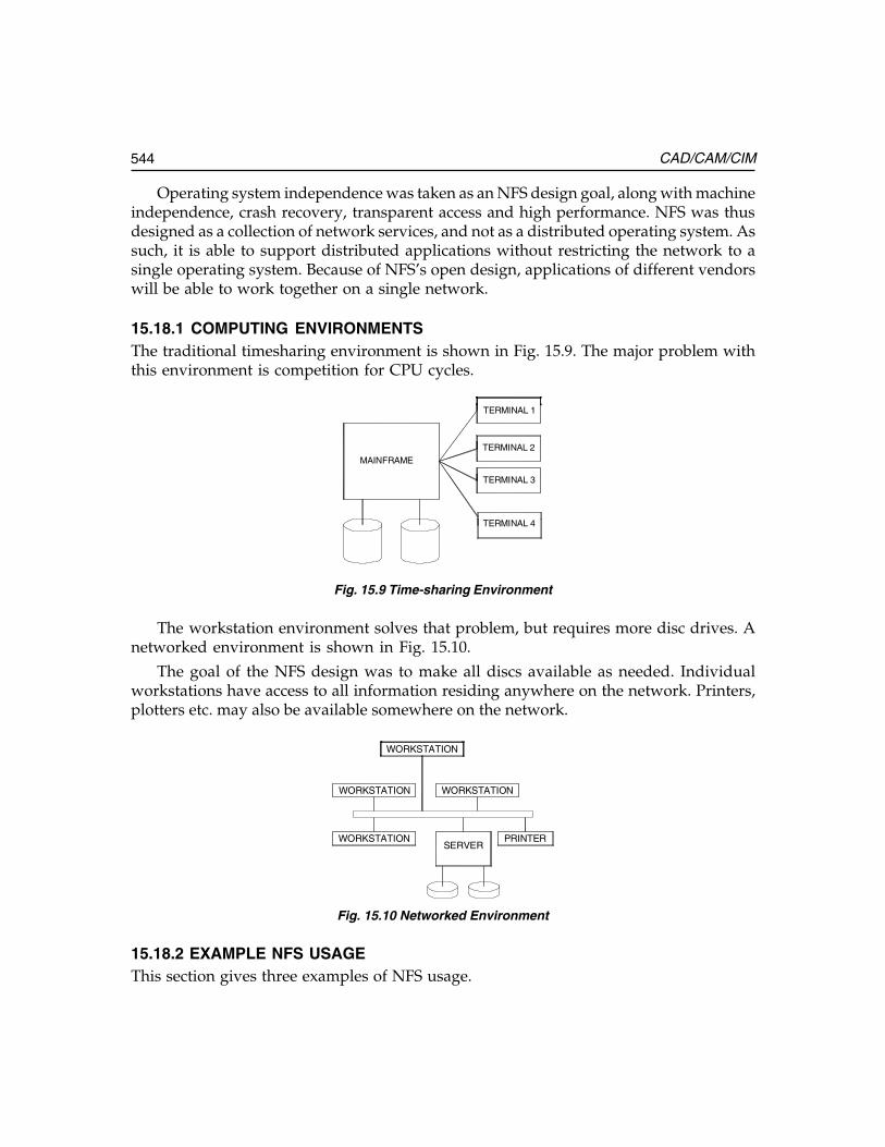
544 CAD/CAM/CIM
Operating system independence was taken as an NFS design goal, along with machineindependence, crash recovery, transparent access and high performance. NFS was thusdesigned as a collection of network services, and not as a distributed operating system. Assuch, it is able to support distributed applications without restricting the network to asingle operating system. Because of NFS’s open design, applications of different vendorswill be able to work together on a single network.
15.18.1 COMPUTING ENVIRONMENTSThe traditional timesharing environment is shown in Fig. 15.9. The major problem withthis environment is competition for CPU cycles.
MAINFRAME
TERMINAL 1
TERMINAL 2
TERMINAL 3
TERMINAL 4
Fig. 15.9 Time-sharing Environment
The workstation environment solves that problem, but requires more disc drives. Anetworked environment is shown in Fig. 15.10.
The goal of the NFS design was to make all discs available as needed. Individualworkstations have access to all information residing anywhere on the network. Printers,plotters etc. may also be available somewhere on the network.
WORKSTATION
WORKSTATION
WORKSTATION
WORKSTATIONSERVER
PRINTER
Fig. 15.10 Networked Environment
15.18.2 EXAMPLE NFS USAGEThis section gives three examples of NFS usage.
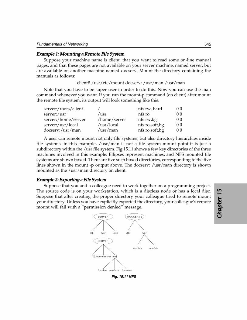
Ch
ap
ter
15C
ha
pte
r 15
Ch
ap
ter
15C
ha
pte
r 15
Ch
ap
ter
15
545Fundamentals of Networking
Example 1: Mounting a Remote File SystemExample 1: Mounting a Remote File SystemExample 1: Mounting a Remote File SystemExample 1: Mounting a Remote File SystemExample 1: Mounting a Remote File SystemSuppose your machine name is client, that you want to read some on-line manual
pages, and that these pages are not available on your server machine, named server, butare available on another machine named docserv. Mount the directory containing themanuals as follows:
client# /usr/etc/mount docserv: /usr/man /usr/man
Note that you have to be super user in order to do this. Now you can use the mancommand whenever you want. If you run the mount-p command (on client) after mountthe remote file system, its output will look something like this:
server:/roots/client / nfs rw, hard 0 0server:/usr /usr nfs ro 0 0server:/home/server /home/server nfs rw,bg 0 0server:/usr/local /usr/local nfs ro,soft,bg 0 0docserv:/usr/man /usr/man nfs ro,soft,bg 0 0
A user can remote mount not only file systems, but also directory hierarchies insidefile systems. in this example, /usr/man is not a file system mount point-it is just asubdirectory within the /usr file system. Fig 15.11 shows a few key directories of the threemachines involved in this example. Ellipses represent machines, and NFS mounted filesystems are shown boxed. There are five such boxed directories, corresponding to the fivelines shown in the mount -p output above. The docserv: /usr/man directory is shownmounted as the /usr/man directory on client.
Example 2: Exporting a File SystemExample 2: Exporting a File SystemExample 2: Exporting a File SystemExample 2: Exporting a File SystemExample 2: Exporting a File SystemSuppose that you and a colleague need to work together on a programming project.
The source code is on your workstation, which is a discless node or has a local disc.Suppose that after creating the proper directory your colleague tried to remote mountyour directory. Unless you have explicitly exported the directory, your colleague’s remotemount will fail with a “permission denied” message.
SE RV ER D OC SE RV E
/lib /usr /etc /lib /usr
/usr/b in /usr/b in
SE RV ER
/ /hom e/server /usr
/usr/b in /usr/lo ca l /usr/m an
Fig. 15.11 NFS
546 CAD/CAM/CIM
To export a directory, first become superuser and then edit the /etc/exports (8) (afterputting this line in /etc/exports):
/usr/proj -access=cohort
If no explicit access is given for a directory, then the system allows anyone on thenetwork to remote mount your directory. By giving explicit access to cohort, you havedenied access to others. The file /etc/xtab contains the entries for directories that arecurrently exported. Now your cohort can remote mount the source directory by issuingthis command:
cohort# /etc/mount client:/usr/proj /usr/proj
This, however, is not the end of the story, since NFS requests are also checked at requesttime. If you do nothing, the accesses that you have established in your /etc/exports filewill stay in effect, but you (and your programs) are free to change them at any time withthe exportfs command and system call. Since both you and your colleague will be able toedit files on /usr/proj, it would be best to use the sccs (source code control system) forconcurrency control.
Example 3: Administering a Server MachineExample 3: Administering a Server MachineExample 3: Administering a Server MachineExample 3: Administering a Server MachineExample 3: Administering a Server MachineSystem administrators must know how to set up the NFS server machine so that client
workstations can mount all the necessary file systems. You can export file systems (thatis, make them available) by placing appropriate lines in the /etc/exports file. Here is asample /etc/exports file for a typical server machine:
/ -access=systems/exec -access=engineering:raj:rupees/usr -access=engineering/home/server -access=engineering/home/local.sun2 -access=engineering:proto/home/local.sun3 -access=engineering
Machine names or net groups, such as staff may be specified after the file system, inwhich case remote mounts are limited to machines that are a member of this net group. Atany time, the system administrator can see which file systems are remote mounted byexecuting the show mount command.
15.18.3 NFS ARCHITECTURETransparent Information AccessUsers are able to get directly to the files they want without knowing the network addressof the data. To the user, all NFS-mounted file systems look just like private discs. There’sno apparent difference between reading or writing a file on a local disc, and reading orwriting a file on a disc in the next building. Information on the network is trulydistributed.
Ch
ap
ter
15C
ha
pte
r 15
Ch
ap
ter
15C
ha
pte
r 15
Ch
ap
ter
15
547Fundamentals of Networking
Different Machines and Operating SystemsNo single vendor can supply tools for all the work that needs to get done, so appropriateservices must be integrated on a network. NFS provides a flexible, operating system-independent platform for such integration.
Easily ExtensibleA distributed system must have an architecture that allows integration of new softwaretechnologies without disturbing the software environment. Since the NFS network-servicesapproach does not depend on pushing the operating system onto the network, but insteadoffers an extensible set of protocols for data exchange, it supports the flexible integrationof new software.
Ease of Network AdministrationThe administration of large networks can be complicated and time-consuming, yet theyshould (ideally) be at least as easy to administer as a set of local file systems on timesharingsystem. The UNIX system has a convenient set of maintenance commands developed overthe years, and the Network Information Service (NIS), a NFS-based network databaseservice, has allowed them to be adapted and extended for the purpose of administering anetwork of machines. The NIS also allows certain aspects of network administration to becentralized onto a small number of file servers, e.g. only server discs must be backed up innetworks of disc less clients.
ReliabilityNFS’s reliability derives from the robustness of the 4.2 BSD file system, from the statelessNFS protocol, and from the daemon-based methodology which network provides serviceslike file and record locking. In addition, the file server protocol is designed so that clientworkstations can continue to operate even when the server crashes and reboots.
The major advantage of a stateless server is robustness in the face of client, server, ornetwork failures. Should a client fail, it is not necessary for a server (or humanadministrator) to take any action to continue normal operation. Should a server or thenetwork fail, it is only necessary that clients continue to attempt to complete NFSoperations until the server or network gets fixed. This robustness is especially importantin a complex network of heterogeneous systems, many of which are not under the controlof professional operations staff.
High PerformanceThe flexibility of NFS allows configuration for a variety of cost performance trade-offs. Forexample, configuring servers with large, high-performance discs, and clients with no discs,may yield better performance at lower cost than having many machines with small,inexpensive discs. Furthermore, it is possible to distribute the file system data across many
548 CAD/CAM/CIM
servers and get the added benefit of multiprocessing without losing transparency. In thecase of read-only files, copies can be kept on several servers to avoid bottlenecks.
15.19 INTERNET
Internet is the mother of all networks and is a gigantic network of networks that connectspresently several million people and millions of computer sites. These computer sites arespread all over the world at various government locations, corporate offices, colleges anduniversities and research institutions. All those people and millions like them who arelinked up to the Internet can talk to each other by way of exchanging electronic messagesin real time.
There are literally hundreds of databases that let people access information rangingfrom CAD data, manufacturing data, medical information, economic data, GIS andengineering tables. This superhighway of information makes available millions and millionsof computer files filled with sound and video clips. Literally anybody can take these andpeople can exchange notes, reviews and views with each other via USENET newsgroupsand bulletin boards.
15.19.1 THE EVOLUTION OF THE INTERNETThe Department of Defense of the United States established a network called ARPANET.It was designed to be an experimental network that supported US military research onnetworks that could withstand disasters like power failures, nuclear or bomb attacks.The idea was that the network must be up and running despite these disasters. Thebasic philosophy was that every computer on the network could talk, as a peer, withany other computer.
So whenever you wanted to send a message on the network, all you had to do was toget onto your computer that would put your data in an envelope, called an Internet Protocol(IP) packet, “address” the data or packets correctly. The communicating computers-notthe network itself—were also given the responsibility to ensure that the communicationwas accomplished. Instrumental in the development of the Internet Protocol was theInternational Standards Organization (ISO) who spent years and years also designing,according to them the ultimate standard in computer networking. Scores of Internetdevelopers in response to market demands started placing the Internet Protocol Softwareon all types of computers. So makers of computers realized that it is the logical method bywhich their computers could communicate to each other. This became a highly attractiveproposition to the US government and the Universities. Everybody had the freedom todecide which one they liked to buy and also expected those computers to work togetherover the network.
A few years’ later Ethernet local area networks (LAN) and workstations with BerkeleyUNIX (which came up with IP networking) appeared on the computing scene. With thearrival of these new workstations a new type of demand was created. Instead of hooking
Ch
ap
ter
15C
ha
pte
r 15
Ch
ap
ter
15C
ha
pte
r 15
Ch
ap
ter
15
549Fundamentals of Networking
up to one large timesharing computer per site, institutions wanted to connect theARPANET to their entire local network. This would allow all the computers on thatLAN to access ARPANET facilities. At the same time, other organizations started buildingtheir own networks using the same communication protocols as the ARPANET namely,IP and its relatives. It became obvious that if these networks could talk together, users onone network could communicate with those on another; everyone would benefit.
One of the most important of these newer networks was the NSFNET, run by theNational Science Foundation (NSF), an agency of the US Government. In the late 80’s theNSF created five supercomputer centres. By creating supercomputer centres, the NSF wasmaking these resources available for any scholarly research. Only five centres were createdbecause they were so expensive — so they had to be shared. This created a communicationsproblem: they needed a way to connect their centres together and to allow the clients ofthese centres to access them.
In response, NSF decided to build its own network, based on the Arpanet’s IPtechnology. It connected the centres with 56,000 bit per second (56 kbps) telephone lines. Itwas however, very expensive. Therefore, they decided to create regional networks. In eacharea of the country, colleges would be connected to a supercomputer centre at one point,and the centres were connected together. With this configuration, any computer couldeventually communicate with any other by forwarding the conversation through itsneighbours.
15.19.2 FILE TRANSFER PROTOCOL (FTP)FTP stands for File Transfer Protocol. It is both a program and the method used totransfer files between computers on the Internet. Anonymous FTP is a type of FTP thatlets the user transfer any of more than 2 million files from several thousand computerson the Internet to the personal computer or computer account. By using FTP, theInternet becomes like a huge disc drive attached to the computer. FTP sites containbooks, journals, software, games, images, sound, multimedia, courseware, datasetsand other information available for the user to transfer. There are a variety of FTPprograms, but most of them work in the same way.
15.19.3 CLIENT/SERVERThe purpose of having computers communicate with each other in a client/server mode isthat they can both share the work. In the early years of computer development, mainframessent information out to dumb terminals, and the mainframe had to do all the work. This alsoallows the user, for example, to take advantage of always-improving client software, whicha user can install in the PC, while the software on the server machine may remain the same.
15.19.4 WORLD WIDE WEB (WWW)World Wide Web is an innovative hypertext front-end program based on client/server architecture that allows the user to access information on the Internet as if
550 CAD/CAM/CIM
it were a part of a seamless web. The goal of WWW is to make all online knowledgepart of one interconnected web of documents and services, and allow the user tofollow facts and texts wherever they might lead. For systems with “character only”displays such as UNIX, DOS and VMS one has to use line browser software inwhich one moves through the web by typing line numbers. On systems likeWindows, X-windows, and Macs these are client programs that allow the user tomake links by clicking and pointing.
15.19.5 INTRANETINTRANET can be defined as a manufacturing organization’s use of world wide web andrelated Internet technology to accomplish its primary objectives, viz., helping in productionof superior quality goods with substantial decrease in operating costs, or achieving totalcustomer satisfaction, maintaining healthy employer—employee relationship etc.
An Intranet is designed to distribute corporate information within an organizationto organization’s own people. Using Intranet, web and related technology can be put tomaximum use to further the purpose of the organization. People may include bothemployees and valuable customers of that organization. In the broadest sense, both internetand intranet use the same technology. However, Intranet is an organizational network,whereas Internet is a global one, which embraces thousands of servers providing widerange of information. Intranet has access to Internet but not vice versa.
Intranets are internal networks that the employees’ can access for information by simplebrowsing as on the world wide web. It acts as a reservoir of company information. It is avery effective platform for the employees to discuss projects and share ideas. Intranetenhances project management and reporting systems and improves workflow and increasesproductivity. Another very significant advantage of intranet is that it permits employeesshare information with colleagues spread over various locations simultaneously. Thefollowing are the major applications of intranet:
i. Mailii. Publishing corporate documents
iii. Access to searchable directoriesiv. Corporate / Department / individual web pagesv. Workgroup collaboration
vi. Software distributionvii. User interface using HTMLA company, which has manufacturing division spread geographically, can make
use of internet technology for effective workflow automation and collaborative productdevelopment or collaborative product commerce. The company can set up intranet atthe headquarters. Each division can have its own intranet, which can be linked to theintranet at the Head Quarters through internet. The divisional intranets can be called
Ch
ap
ter
15C
ha
pte
r 15
Ch
ap
ter
15C
ha
pte
r 15
Ch
ap
ter
15
551Fundamentals of Networking
extranets. Thus, the entire manufacturing organization can be linked into a singlenetworked entity.
15.20 HARDWARE ELEMENTS OF A NETWORK
Introduction of CIM necessitates every manufacturing engineer to be aware of the basichardware elements of a network. The components required for a small network (sayrestricted to a computerized design action or production planning department) havebeen described earlier. This section gives a brief overview of these elements used in anEthernet network, which can cover an entire manufacturing plant.
15.20.1 LAN ADAPTERSThese adapters are used for client workstations running DOS and Windows or OS/2 orfor servers with ISA buses. Network adapters have been discussed in an earlier section.The LAN Adapter for Ethernet provides installation flexibility with connections for10BaseT, 10Base2 and AUI.
Features:Features:Features:Features:Features:• Support for 8 or 16 bit ISA slots.• Software configurability.• Programmed I/O or shared memory mode operation.• Support for Novell Netware, Banyan VINES, Artisoft LANtastic SCO, UNIX,
Microsoft Windows NT, DEC Patchworks. IBM OS/2 LAN Server and MicrosoftLAN Manager networking operating systems.
• Remote Program Load.• Diagnostic check and power-up.
15.20.2 ETHERNET SWITCHUsing high-speed, parallel paths among connected Ethernet LAN segments and devicesuses Ethernet Switch to increase bandwidth 400 percent. By using this switch, LANcongestion is reduced, so frequent LAN users get extra capacity without crowding outothers on the same network.
Features:Features:Features:Features:Features:• Lowers costs per port without adding bridges and routers.• Connects to a variety of hubs and concentrators.• Provides aggregate bandwidth of up to 100Mbps through media speed frame
transfer between four pairs of ports.• Supports large, high-speed switch networks by using up to four full duplex links
for a maximum bandwidth of 100 Mbps.• Improves security by controlling traffic flow to specific addresses or within a
defined group of virtual switch ports.• Enables remote configuration and microcode download.
552 CAD/CAM/CIM
15.20.3 ETHERNET WORKGROUP HUBSWorkgroup hubs allow the addition of up to 8 or 16 stations to an existing Ethernetnetwork to prevent network congestion. They automatically partition any port connectedto a device, which generates repeated collisions, and re-enable the port when the conditionclears. They are also pathways to continued network growth.
Features:Features:Features:Features:Features:
• Contains 8 or 16 10BaseT ports.• Includes an uplink port for cascading multiple 8222s between 10BaseT ports.• Simplifies set-up via plug and play installation.• Detects polarity reversal on cables connected to 10BaseT ports.• Indicates status of power, collisions and connections via LEDs.
15.20.4 WIRELESS LAN ADAPTERSThese adapters provide seamless LAN access to any unwired PC. One can even create aLAN among notebook PCs in conference rooms, airplanes - anywhere.
Features:Features:Features:Features:Features:
• Uses diffused infrared light. So transmissions are secure and do not have to beaimed.
• Includes cables for external infrared transceivers for communications within aradius of 6 m.
• Provides seamless bridging and roaming support for Token-Ring and Ethernetnetworks.
• Extends existing LANs via infrared-enabled bridges or routers.• Supports different device drivers.• Works with industry-standard computers.• Provides a 1Mbps data transfer rate.• Supports IBM LAN Support Program, IBM TCP/IP, Artisoft, LANtastic, Netware,
Personal NetWare, NetWare Lite and Windows for Workgroups.
15.20.5 FDDI ADAPTERSThe Fiber Distributed Data Interface (FDDI) delivers the bandwidth you need for even themost demanding network applications. Micro Channel, ISA and EISA systems benefit from100Mbps speed to the desktop—just the capacity you require for today’s graphics intensiveapplications. The newest FDDI Adapters deliver this fast throughput over existing UTP type5 or FTP copper cabling providing a low cost upgrade to a high performance network.
Features:Features:Features:Features:Features:• Supports ANSI X3T9.5 and ISO 9314 standards.
Ch
ap
ter
15C
ha
pte
r 15
Ch
ap
ter
15C
ha
pte
r 15
Ch
ap
ter
15
553Fundamentals of Networking
• Compatible with today’s leading operating systems such as DOS, OS/2,Windows, Windows NT, Netware, SFT III and UNIX.
• Provides synchronous frame transmission and bandwidth allocation formultimedia and time critical applications.
• Includes Remote Program Update.
15.20.6 FDDI WORKGROUP CONCENTRATORThe workgroup concentrator is a low cost hub solution. It works with existing hubs toserve as a high-speed link or backbone.
Features:Features:Features:Features:Features:
• Links up to 12 devices via fiber as well as shielded and unshielded twisted paircopper connections.
• Extends 8240 functionality to serve as an entry-level FDDI concentrator or“collapsed backbone” for small workgroups or LAN extensions.
• Includes SMT and SNMP network management protocols.
15.20.7 TOKEN-RING ADAPTERSToken-Ring adapters are available for ISA, EISA, PCMICA, Micro Channel and PCIbuses. They offer low price, easy installation, reduced network maintenance costs, andenhanced functionality.
Features:Features:Features:Features:Features:
• Full duplex enabled so that when attached to a full duplex Token Ring switch,the available bandwidth can be increased to 32 Mbits/sec.
• Support for Ring-Speed Listen that senses the speed of a Token Ring andautomatically configures the adapter to 4 or 16 Mbits/sec.
• Software configurable, with graphical installation software to simplify set up.• Auto media detect that senses the type of media connection and automatically
configures the adapter to Unshielded Twisted Pair (UTP) or Shielded TwistedPair (STP).
• MAC addresses located on the outside of the adapter for quick diagnostics.• Switchless (no DIP switches or jumpers to set).
15.20.8 ROUTER
Many branch networks need a cost-effective, high performance multi-protocol routingand bridging solution that connects to the main network. A router serves this purpose.
554 CAD/CAM/CIM
15.21 ATM (ASYNCHRONOUS TRANSFER MODE) NETWORKS
Transfer mode defines how information supplied by network users is eventually mappedonto the physical network. It is also a technique used for transmission, multiplexing andswitching aspects of a communication network.
According to the architecture and techniques used to transfer data, networks used canbe categorized into two. They are:
(i) Circuit Switched Networks(ii) Packet Switched Networks
Circuit SwitchingCircuit Switching is mostly used for telephone networks. Here the bandwidth ismultiplexed among the transmitting stations, each having a fixed bandwidth. A circuitis established between the two entities to exchange information for the complete durationof the connection. Each channel has a fixed bandwidth. Several channels can bemultiplexed onto a link and translating the incoming channel number to the outgoingchannel number performs switching. Before the data can start flowing, a collection ofconsecutive channels are reserved from source to destination by signaling. Once thecircuit is established, the traffic flows continuously during the duration of the connection.
Packet SwitchingPacket Switching is a scheme in which user messages are segmented into packets beforethey are transmitted. The size of the packet is restricted to some maximum value. By doingthis, reception and transmission of packets of a message can be overlapped, therebyreducing end to end delay of messages. Essentially, each packet in the network is treatedas an independent entity. However, they are required to be reassembled at the receiver toform the original information unit before being passed to the user. Early work in supportingreal time applications together with data applications in integrated networks was connectedin a variant of packet switching known as Fast Packet Switching (FPS).
In the fast packet switching scheme, a packet could be transmitted from an intermediatemode, even before it is completely received, thereby further reducing the end-to-end delay.However, Fast Packet Switching with variable length packets results in complex switchingfabric and buffer management schemes, as the transmission speeds increase. Hence theyhave a ceiling for the bit transfer rates. FPS schemes were modified suitably to support B-ISDN applications. One such instance of the FPS is the Asynchronous Transfer Mode (ATM)shown in Fig 15.12, which provides connection-oriented service employing small, fixedlength packets known as cells of size 53 bytes.
Features:Features:Features:Features:Features:• The fixed small cell sizes, result in simplified buffer management and switching
fabric design. The buffer sizes at the intermediate nodes are expected to be small,thereby bounding the cell delay.
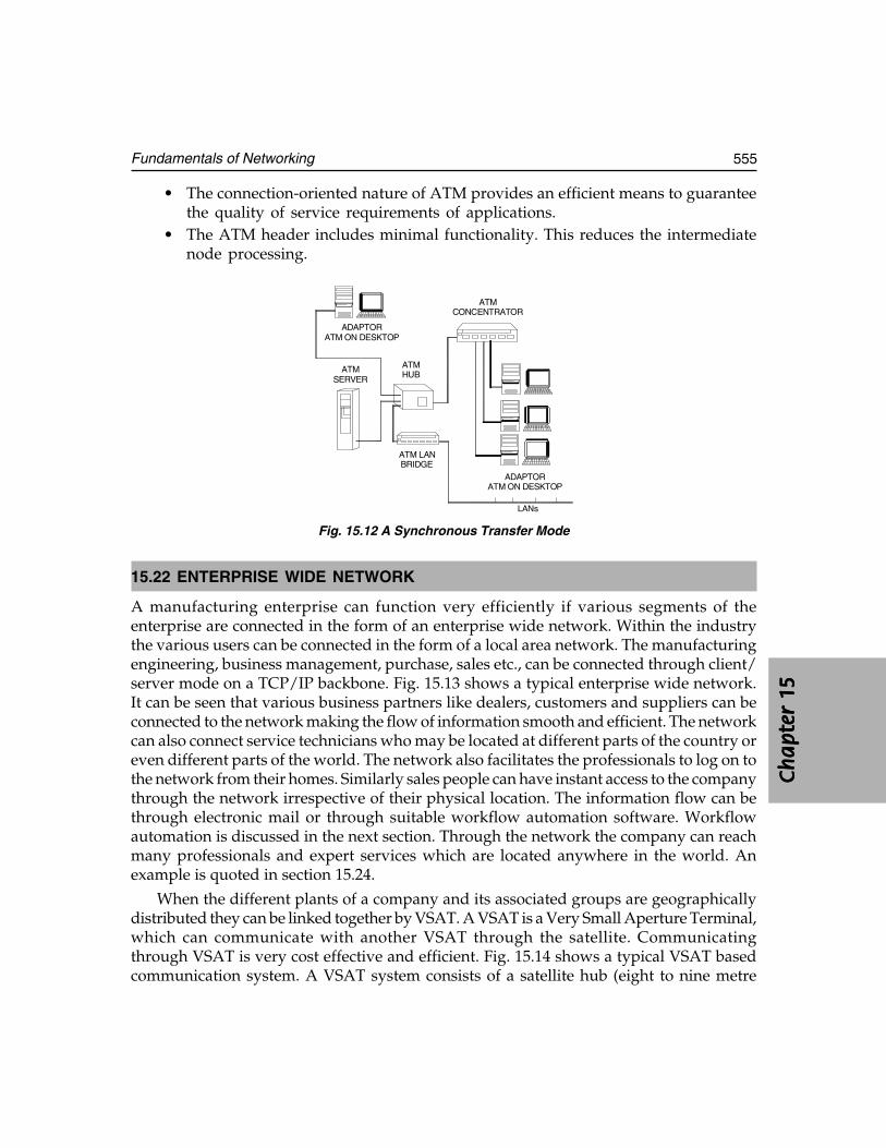
Ch
ap
ter
15C
ha
pte
r 15
Ch
ap
ter
15C
ha
pte
r 15
Ch
ap
ter
15
555Fundamentals of Networking
• The connection-oriented nature of ATM provides an efficient means to guaranteethe quality of service requirements of applications.
• The ATM header includes minimal functionality. This reduces the intermediatenode processing.
ATMCONCENTRATOR
ATMSERVER
ATMHUB
ATM LANBRIDGE
ADAPTORATM ON DESKTOP
ADAPTORATM ON DESKTOP
LANs
Fig. 15.12 A Synchronous Transfer Mode
15.22 ENTERPRISE WIDE NETWORK
A manufacturing enterprise can function very efficiently if various segments of theenterprise are connected in the form of an enterprise wide network. Within the industrythe various users can be connected in the form of a local area network. The manufacturingengineering, business management, purchase, sales etc., can be connected through client/server mode on a TCP/IP backbone. Fig. 15.13 shows a typical enterprise wide network.It can be seen that various business partners like dealers, customers and suppliers can beconnected to the network making the flow of information smooth and efficient. The networkcan also connect service technicians who may be located at different parts of the country oreven different parts of the world. The network also facilitates the professionals to log on tothe network from their homes. Similarly sales people can have instant access to the companythrough the network irrespective of their physical location. The information flow can bethrough electronic mail or through suitable workflow automation software. Workflowautomation is discussed in the next section. Through the network the company can reachmany professionals and expert services which are located anywhere in the world. Anexample is quoted in section 15.24.
When the different plants of a company and its associated groups are geographicallydistributed they can be linked together by VSAT. A VSAT is a Very Small Aperture Terminal,which can communicate with another VSAT through the satellite. Communicatingthrough VSAT is very cost effective and efficient. Fig. 15.14 shows a typical VSAT basedcommunication system. A VSAT system consists of a satellite hub (eight to nine metre
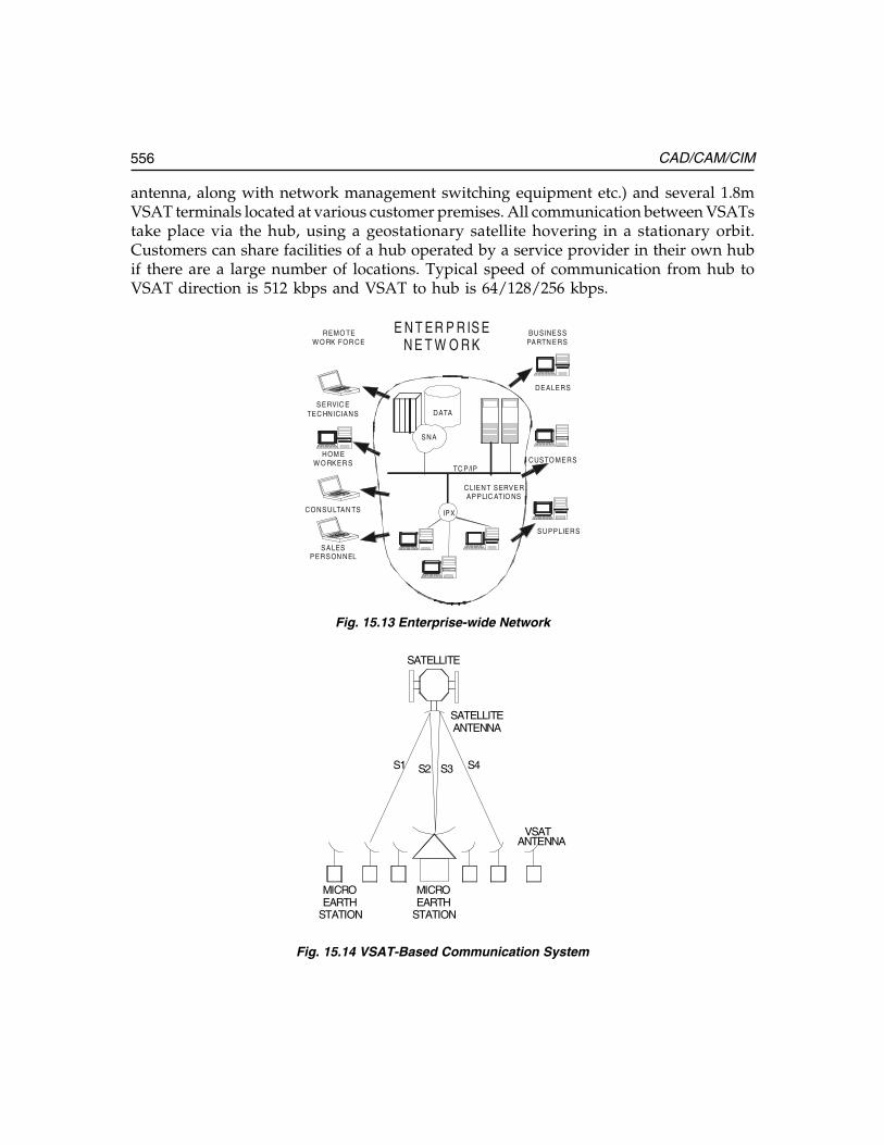
556 CAD/CAM/CIM
antenna, along with network management switching equipment etc.) and several 1.8mVSAT terminals located at various customer premises. All communication between VSATstake place via the hub, using a geostationary satellite hovering in a stationary orbit.Customers can share facilities of a hub operated by a service provider in their own hubif there are a large number of locations. Typical speed of communication from hub toVSAT direction is 512 kbps and VSAT to hub is 64/128/256 kbps.
SNA
TC P/IP
DEALERS
CUSTO MERS
SUPPLIERS
IPXCONSULTAN TS
SALESPERSON NEL
HOM EW O RKER S
SERVIC ETEC HN ICIANS
REMO TEW O RK FOR CE
BUSINESSPARTN ERS
DATA
CLIENT SERVERAPPLIC ATIO NS
E N T ER P R IS EN E T W O R K
Fig. 15.13 Enterprise-wide Network
SATELLITEANTENNA
VSATANTENNA
S1 S2 S3 S4
MICROEARTH
STATION
MICROEARTH
STATION
SATELLITE
Fig. 15.14 VSAT-Based Communication System
Ch
ap
ter
15C
ha
pte
r 15
Ch
ap
ter
15C
ha
pte
r 15
Ch
ap
ter
15
557Fundamentals of Networking
15.23 DOCUMENT AND WORKFLOW MANAGEMENT SYSTEM
Computer Integrated Manufacturing can reduce paper documents to a considerableextent, apart from improving the communication among various segments involved inmanufacture.
Some estimates show that manufacturing industries now consume twice as much paperfor document preparation and development as they did a few years ago. That means twiceas many documents cross engineer’s desk, and twice as many reviews and approvals haveto be looked over and forwarded. More seriously engineers have a large number of electronicfiles to manage too. This means heavy workload for staff. This also results in loss inproductivity and accidental errors (overwritten and deleted files, for example).
15.23.1 PAPERLESS OFFICEThe introduction of desktop computers led to the use of hundreds of electronic files. Thishas necessitated the following:
Better tools for document creation: Better tools for document creation: Better tools for document creation: Better tools for document creation: Better tools for document creation: Easier ways to create and edit documents meanmore documents get produced.
Archival necessity:Archival necessity:Archival necessity:Archival necessity:Archival necessity: The engineers have to revise, distribute and archive documents(and all their iterations) over many years for many more people. To meet these regulationsthe engineer must handle and track documents differently than before.
Lean organizations:Lean organizations:Lean organizations:Lean organizations:Lean organizations: As organizations strive to become more efficient, fewer staffmembers must manage the same amount of information.
Shorter business cycles: Shorter business cycles: Shorter business cycles: Shorter business cycles: Shorter business cycles: Time is money, and today’s clients want higher quality,shorter lead times and lower costs than ever before. Companies compete fiercely inregional and global markets. They compete most successfully when they adopt “parallelprocessing” techniques, when they use resources and manage processes—design,engineering, drafting, manufacturing - concurrently rather than sequentially. The resultis more electronic and paper documentation.
Changes in the means of communication:Changes in the means of communication:Changes in the means of communication:Changes in the means of communication:Changes in the means of communication: If the engineers do not keep up withtechnological changes, they lose their competitive edge. Ever-faster PCs and printers, faxes,e-mail, network servers and information superhighway are all to be used to speed upengineers’ tasks. Today employees generate many more documents. Information is createdfaster, reviewed by more people, and distributed more widely.
Many manufacturing managers underestimate the negative impact of poor documentmanagement on productivity. They believe that existing procedures provide adequatesecurity and that finding documents is a “nuisance” rather than a serious threat toproductivity. However, mismanaged files may cause significant delay in project completion.
Manual procedures developed to manage paper drawings are simply inadequate forelectronic documents - no matter how small or large the manufacturing company is. In
558 CAD/CAM/CIM
fact, small companies probably pay an even higher price for ineffective documentmanagement than their larger competitors. Smaller companies cannot absorb the extracosts that result from mismanaged documents and workflow. They have fewer employeesto handle a crisis and fewer cash reserves for overruns. And they more quickly lose theircompetitive edge when poor security leads to error.
15.23.2 MANAGING DRAWINGS ELECTRONICALLYIf the manufacturing engineer has a computer, he can manage drawings electronically.But he needs a document management system to do it - one that lets him maintain, accessand manipulate drawings and related information quickly, securely, cost effectively. Aquality document management system can:
• Display document information on custom electronic “file” cards.• Organize drawings and related documents into folders that can be restructured
without physically moving files.• List all drawings and related documents currently being worked on by anyone
of the staff.• Ensure that drawings and related information can be easily located and search
parameters saved for future use.• Make document “behaviour” user definable.• Store all drawings and related documents in a secure, central location.• Monitor authorization and access rights to maintain security.• Automatically back up selected (or all) drawings and related documents.• Automate workflow by automatically routing drawings, related documents and
instructions/messages to all relevant staff - from approvers to reviewers tomanagers - and tracking individual responses and revisions.
15.23.3 THE FUNDAMENTALS OF TECHNICAL DOCUMENT MANAGEMENTA viable document management system helps the manufacturing engineer to find thefiles he needs. It makes it easy to find out what is in them and lets him edit them with theprogram appropriate to the job. It should have the organization and access features andbenefits described below:
• Flexible organization:Flexible organization:Flexible organization:Flexible organization:Flexible organization: A single, fixed document organization is not adequate.Electronic document must often appear in more than one “folder”, but one doesnot want to duplicate files. The system should organize documents into foldersthat can be reorganized at any time without physically moving documents. Thebest systems group documents dynamically by specific tasks, projects or designphases. Users can change these groupings to view documents in the formatappropriate to their task. For example, the team leader might view informationorganized by discipline and document type, whereas the designer prefers projectand plot sheet.
Ch
ap
ter
15C
ha
pte
r 15
Ch
ap
ter
15C
ha
pte
r 15
Ch
ap
ter
15
559Fundamentals of Networking
• Document types:Document types:Document types:Document types:Document types: File types, typically indicated by a file extension (.DBF, .DWG,.TXT, .DOC, .DXF etc.) are inadequate for organizing and managing electronicdocuments. An effective document management system lets the user definedocument types that relate to the work you do. For example, AutoCAD filesmight be differentiated into Plans, Sections and Elevations (AEC) or Assemblyand Part (Mechanical). Each document should have a specific program associatedwith it for editing, viewing, redlining or printing.
• Document names:Document names:Document names:Document names:Document names: An effective document management system should let theengineer use longer, more meaningful file names and view them from within hisapplications.
• Easy to access profile information:Easy to access profile information:Easy to access profile information:Easy to access profile information:Easy to access profile information: The user should be able to quickly and easilyview document name, author, creation and revision dates, revision number, anda list of related documents. He should be able to modify profile information atany time and to save custom information with each document and each revision.All documents checked out to a user should be displayed in a single list.
• Document search capability:Document search capability:Document search capability:Document search capability:Document search capability: Searches of the common document storage areashould allow the user to obtain a list of documents meeting specific criteria. Oneneed not have to know complex query parameters or Structured Query Language(SQL) commands to complete these searches. One should be able to define andsave common searches and rapidly access them through dialog boxes, scrollinglists and user intuitive sequences. More complex searches with prompts shouldstill be easy to create and save, so that less-experienced staff can run them.
• Document security:Document security:Document security:Document security:Document security: For some companies, “document security” means carefullyrestricting access to sensitive information - financial reports, sales plans, personneldata. But designs and drawings are corporate assets, too, and should be securedfrom inadvertent deletion or overwriting. The engineers may also need to ensurethat unqualified people does not edit design documents.
• Managing documents—Managing documents—Managing documents—Managing documents—Managing documents—Revisions: To avoid user confusion and error, a documentmanagement system should automatically save and sequentially number allrevisions. It should limit on-line revisions by automatically archiving or deletingearlier versions.Information associativity: When a drawing is revised, the document managershould distinguish which associated documents should be linked to the newrelease, and which, to the original.Quick comparison: Occasionally one will want to compare two revisions of adrawing. With a “compare” feature, the document management system visuallyhighlights the differences between two files, so one can easily choose the right one.
• Document viewing: Document viewing: Document viewing: Document viewing: Document viewing: Any document management system should include extensive,quickly generated, built in viewing capabilities.Multi-format viewing:Multi-format viewing:Multi-format viewing:Multi-format viewing:Multi-format viewing: The system must handle all the documents with whichone works. For each file type, one should be able to view, search and print
560 CAD/CAM/CIM
documents - even if one does not have immediate access to the application withwhich they were created. And if the software cannot handle a particularformat, adding a third party viewer application for that format should be aneasy job.
• Thumbnails:Thumbnails:Thumbnails:Thumbnails:Thumbnails: Some systems provide a thumbnail of each document so one caninstantly see what it is, regardless of format.
• Redlining:Redlining:Redlining:Redlining:Redlining: Redlining lets the user correct or comment on a drawing withoutchanging the drawing itself. Redlining also allows non-CAD oriented users toeasily pass comments to design. However, a red line file must be a separate file,and the document management system must track the relationship between theoriginal and the red line.
15.23.4 AUTOMATING WORKFLOWWorkflow automation should help the manufacturing engineer share and routedocuments in the manner best suited to the team. It must be tightly linked to the system’sdocument management features and facilitate the adhoc interactions common in thedesign process.
A workflow automation system should provide electronic document routing, alerts,automatic event notifications and electronic approvals.
The following attributes are required for a document management system:
• Sharing of information:Sharing of information:Sharing of information:Sharing of information:Sharing of information: Successful workflow automation begins with clearsystem procedures and easy-to-use communication and information sharingprocesses. As a standard feature, the system must provide task routing withall relevant documents attached.For example, an action slip, with documents attached, is routed to the team,recipients see it on e-mail, and the system tracks responses. The system shouldallow the user to route work requests to predefined teams. Thus, a project managercreates a change order, attaches the relevant drawing, and routes it as needed.
• Alerts:Alerts:Alerts:Alerts:Alerts: The team leader or other user can specify the sequence of individuals foredit or review of a series of documents. When team members do not respondwithin a given time, the system should alert the message originator and theperson responsible for the delay.
• Approvals:Approvals:Approvals:Approvals:Approvals: An electronic approval system allows supervisory staff to approvedesigns and changes rapidly, eliminating the delays inherent in paper-based approvalloops. The software should not only route documents for approvals, but alsoautomatically designate a document as “approved” and alter the revision number.Usually, several team members review and comment on different project phasesallowing them to work with the same documents, compiling individual comments,and updating associated documents. Since these actions are performedelectronically, the traditional paper file is no longer necessary.
Ch
ap
ter
15C
ha
pte
r 15
Ch
ap
ter
15C
ha
pte
r 15
Ch
ap
ter
15
561Fundamentals of Networking
• Event notification: Event notification: Event notification: Event notification: Event notification: A tightly integrated workflow automation and documentmanagement system can notify the user when certain changes are made to adocument. For example, a manager may want to know when someone checksout a specific document for editing. An engineer may want to be notified whena component or assembly drawing has been modified. You should be able toconfigure this kind of event notification to work on specific documents, for avariety of events, and to notify either single users or entire groups.
A good technical document management and workflow automation system must beeasy to use. The following are the attributes of a good system:
• Transparent user operations:Transparent user operations:Transparent user operations:Transparent user operations:Transparent user operations: Software with a friendly user interface means lesstime to train employees.
• CAD software integration: CAD software integration: CAD software integration: CAD software integration: CAD software integration: The document management and workflow automationsoftware should function as an extension of the CAD system, not as a separateapplication. This improves productivity.
• Bulk downloading:Bulk downloading:Bulk downloading:Bulk downloading:Bulk downloading: Whether one needs to access entire projects or electroniclibraries of details or parts, he/she should be able to easily import large numbersof documents into the system.
• System performance:System performance:System performance:System performance:System performance: All computerized document management and workflowautomation systems use a database “engine”. This responds quickly to userrequests.
Response times depend on many factors - for example, network performancecapabilities, number of users simultaneously accessing the database and re-indexing speed.Background processing can also significantly affect system performance.
15.23.5 ADVANTAGES OF WORKFLOW MANAGEMENT SYSTEMS
i.i.i.i.i. Individual Productivity:Individual Productivity:Individual Productivity:Individual Productivity:Individual Productivity:Every person on the team using a document management and workflow automationsystem will become more productive. For example, the new system will eliminatemanual searches for files when edits must be made. Check-in/check-out featureswill guard against accidental overwrites and unintentional revisions.
ii.ii.ii.ii.ii. Increase in Team Productivity:Increase in Team Productivity:Increase in Team Productivity:Increase in Team Productivity:Increase in Team Productivity:The typical design process has several phases. In every phase, documents arecontinuously created, reviewed and revised. A document management andworkflow automation system reduces rework and shortens review cycles. Itimproves communications and helps the member of the team to easily finddrawings and other files. The review cycle is shorter because you route documentsto several people at once rather than to one person at a time.
A document management and workflow automation system will also affect the waythe team manages design changes. Changes made early in the design process areinexpensive to implement and vice versa. Indeed, late changes can upset the whole project
562 CAD/CAM/CIM
schedule. Yet in most companies, design changes increase as the project nears completion.These changes are incorporated incurring substantially high costs. Any tools that helpyour team make changes earlier generate savings.
Thus Workflow automation software is an enabling tool for concurrent engineering.
15.24 A CASE STUDY OF APPLICATION OF GLOBAL NETWORKING
There are a number of success stories of application of use of computer networks forproduct development and modification. The following example of application ofconcurrent engineering appeared in Industrial World, July 3, 1995.
This story is related to the product development in a company called VeriFone Inc.,Redwood city, California, and a maker of transaction automation equipment. Theiroperations are such that on a typical project a software engineer in Hawaii might collaboratewith mechanical engineers in California and Taiwan and printed circuit board designersin Paris. They have a strong packaging design group in Taiwan and if a complicatedenclosure is to be designed they get it done in Taiwan. The activities are thus allocated tothe sites where strength exists.
Rather than having the different development centers work on their own specificprojects, VeriFone brings a number of the globally dispersed sites into the development ofeach new product. With Global networking geographic distances can be turned into acompetitive advantage. For e.g.VeriFone has a development centre in Bangalore, India, totake advantage of the high quality engineering manpower available in this region and onein Paris to gain access to European technologies.
Even time difference between locations can be an advantage to respond to requestfor design changes. For example, when an engineer who works in Hawaii receives anurgent request later in the day he will send it immediately to Bangalore or Taipei whereit is earlier in the day. The person who receives the request can access the related CADfiles, make the necessary changes and send the design changes back to the person whohas requested it. Depending upon where the person lives the new design is available atthe start of his next working day.
With this global approach VeriFone has cut short its product development cycledown to as short as seven months to complete the project. The key to making developmentwork globally is a highly effective communication system, which includes a computernetwork and video conferencing.
The technological foundation of VeriFone’s global development strategy is an extensivecomputer network. VeriFone has a gateway to the internet and users can log onto thecomputer system from anywhere in the world via CompuServe. A Motif based programgives every engineer regardless of location, access to every file in the company. The networksupports the company’s E-mail system, which is the main form of communication at thiscompany. Through E-mail any employee can reach any other employee in the entire
Ch
ap
ter
15C
ha
pte
r 15
Ch
ap
ter
15C
ha
pte
r 15
Ch
ap
ter
15
563Fundamentals of Networking
company instantaneously, Customers also use E-mail for communication.Videoconferencing is another technology to foster international communication. Rarelywill all engineers on a particular project gather in the same room, but they will meet fromtime to time in a videoconference.
QUESTIONS
1. Discuss the need and advantages of networking in a manufacturing shop.2. Differentiate between LAN, MAN and WAN.3. What are the different components of a LAN?4. Describe different interfaces used in transmitting signals.5. Explain the working of a modem.6. Describe the three basic network topologies.7. Explain the functions of each layer in ISO-OSI.8. Describe the salient features of MAP and TOP.9. What are the commonly used network interface cards?
10. Study a LAN and prepare a brief report on the functions of a network operatingsystem.
11. Discuss how you will carry out a design in a networked environment.12. Study a manufacturing shop and prepare a document on networking the computer
related equipment on the shop floor.13. How does a network help design activity where a large number of engineers are
involved?14. What are the requirements of an enterprise wide network?15. How does workflow automation software help to improve team productivity?16. What are the advantages of using workflow automation software?17. Why is VSAT an essential tool for a CIM company?18. How will you use internet to advantage to implement CIM?

This pageintentionally left
blank
�������������
��������
� ����
World Wide Web and Internet have brought about significant changes the way engineeringdesign and manufacturing activities are being carried out. It is now possible for differentteams to work together on diverse platforms in geographically distributed locations andcomplete the product design and development efficiently. The technologies evolving thatmake this possible are discussed in this chapter.
16.1 INTRODUCTION
Large engineering projects involve co-ordinated work of hundreds of engineers workingin small or large teams. Computer integrated manufacturing environment makes thispossible because of the possibility of data transfer between different applications. However,to day the necessity to collaborate between teams working in places far apart has arisen.For example, the design of an add on board for a new generation computer may be carriedout in the Silicon Valley, USA. The engineers working in the development group generatethe product data. The testing may be undertaken at Chennai. The product data is transferredvia Internet to the manufacturing company in South Korea to make the chips. The printedcircuit board may be made in Malaysia. A firm in Singapore may assemble the product.This is shown in Fig. 16.1. The members in entire team involved collaboratively workusing the Internet.
On the face of it may appear to be a sequential task. In reality Intranet and Internetpermit the design, manufacturing and testing teams to collaborate during the developmentphase itself so that the product can be introduced in the market as early as possible. Thecompany can also share the design data with the prospective users long before the productis manufactured. For example, let us assume that a company is developing 40 GB disc drives.Long before the product is launched in the market the manufacturer can pass on the data onthis disk drive so that the computer manufacturers can start developing new computerswith this disk drive. As soon as the disk drive is made available, new computers can
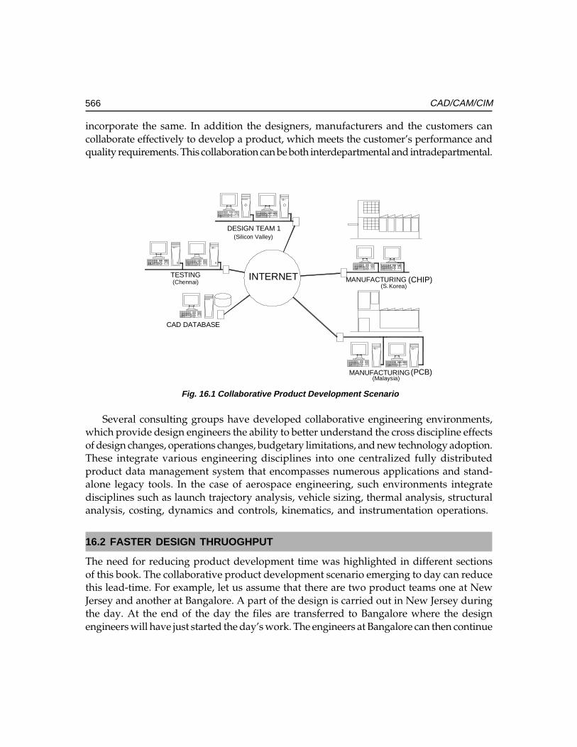
566 CAD/CAM/CIM
incorporate the same. In addition the designers, manufacturers and the customers cancollaborate effectively to develop a product, which meets the customer’s performance andquality requirements. This collaboration can be both interdepartmental and intradepartmental.
INTERNET
DESIGN TEAM 1
CAD DATABASE
MANUFACTURINGTESTING
MANUFACTURING
(CHIP)
(PCB)
(Silicon Valley)
(Chennai)
(Malaysia)
(S.Korea)
Fig. 16.1 Collaborative Product Development Scenario
Several consulting groups have developed collaborative engineering environments,which provide design engineers the ability to better understand the cross discipline effectsof design changes, operations changes, budgetary limitations, and new technology adoption.These integrate various engineering disciplines into one centralized fully distributedproduct data management system that encompasses numerous applications and stand-alone legacy tools. In the case of aerospace engineering, such environments integratedisciplines such as launch trajectory analysis, vehicle sizing, thermal analysis, structuralanalysis, costing, dynamics and controls, kinematics, and instrumentation operations.
16.2 FASTER DESIGN THRUOGHPUT
The need for reducing product development time was highlighted in different sectionsof this book. The collaborative product development scenario emerging to day can reducethis lead-time. For example, let us assume that there are two product teams one at NewJersey and another at Bangalore. A part of the design is carried out in New Jersey duringthe day. At the end of the day the files are transferred to Bangalore where the designengineers will have just started the day’s work. The engineers at Bangalore can then continue
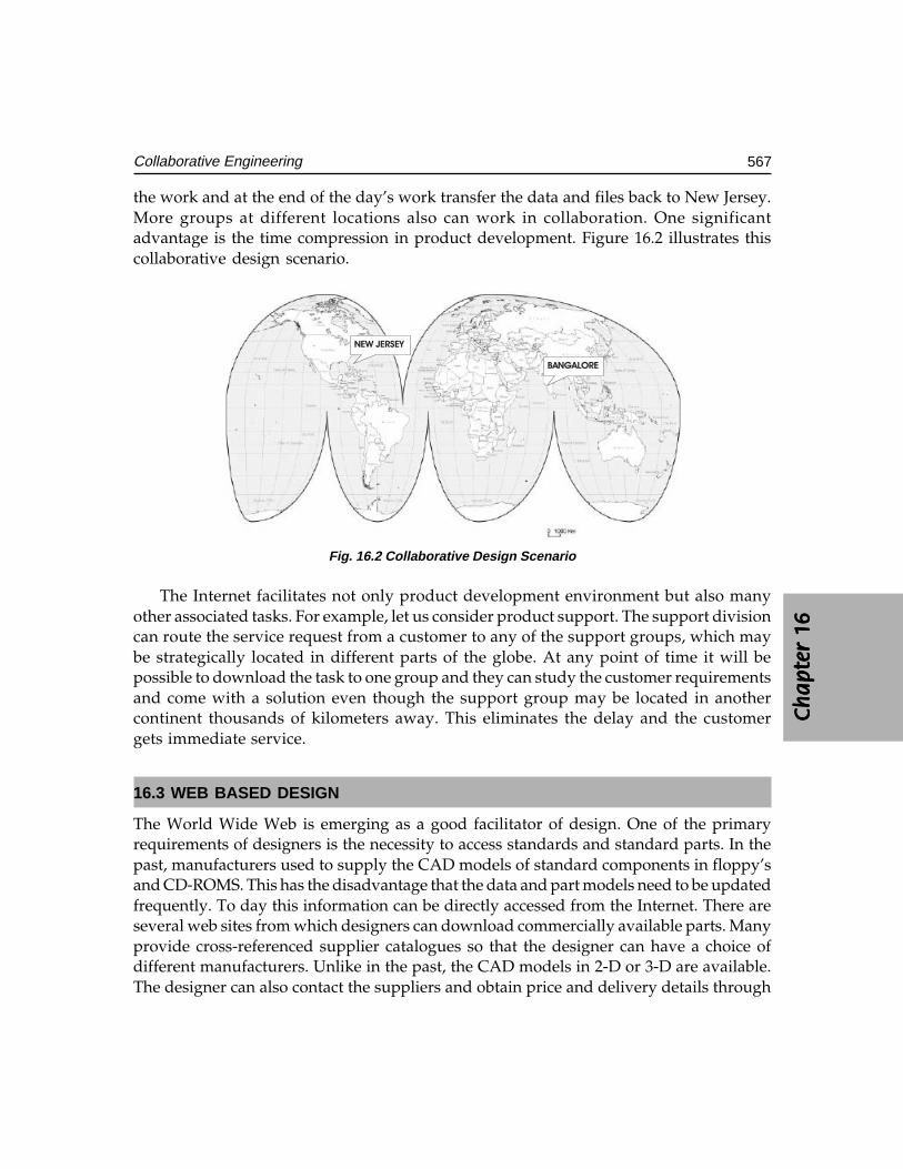
Ch
ap
ter
16C
ha
pte
r 16
Ch
ap
ter
16C
ha
pte
r 16
Ch
ap
ter
16
567Collaborative Engineering
the work and at the end of the day’s work transfer the data and files back to New Jersey.More groups at different locations also can work in collaboration. One significantadvantage is the time compression in product development. Figure 16.2 illustrates thiscollaborative design scenario.
����������
��� ��
Fig. 16.2 Collaborative Design Scenario
The Internet facilitates not only product development environment but also manyother associated tasks. For example, let us consider product support. The support divisioncan route the service request from a customer to any of the support groups, which maybe strategically located in different parts of the globe. At any point of time it will bepossible to download the task to one group and they can study the customer requirementsand come with a solution even though the support group may be located in anothercontinent thousands of kilometers away. This eliminates the delay and the customergets immediate service.
16.3 WEB BASED DESIGN
The World Wide Web is emerging as a good facilitator of design. One of the primaryrequirements of designers is the necessity to access standards and standard parts. In thepast, manufacturers used to supply the CAD models of standard components in floppy’sand CD-ROMS. This has the disadvantage that the data and part models need to be updatedfrequently. To day this information can be directly accessed from the Internet. There areseveral web sites from which designers can download commercially available parts. Manyprovide cross-referenced supplier catalogues so that the designer can have a choice ofdifferent manufacturers. Unlike in the past, the CAD models in 2-D or 3-D are available.The designer can also contact the suppliers and obtain price and delivery details through
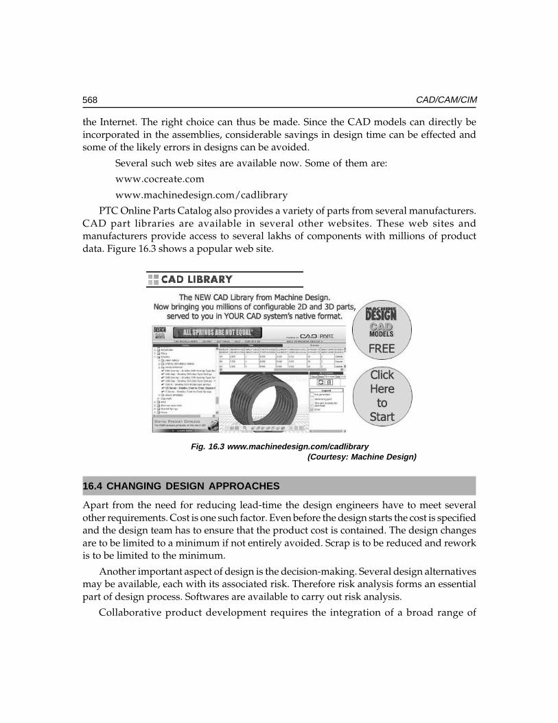
568 CAD/CAM/CIM
the Internet. The right choice can thus be made. Since the CAD models can directly beincorporated in the assemblies, considerable savings in design time can be effected andsome of the likely errors in designs can be avoided.
Several such web sites are available now. Some of them are:
www.cocreate.com
www.machinedesign.com/cadlibrary
PTC Online Parts Catalog also provides a variety of parts from several manufacturers.CAD part libraries are available in several other websites. These web sites andmanufacturers provide access to several lakhs of components with millions of productdata. Figure 16.3 shows a popular web site.
Fig. 16.3 www.machinedesign.com/cadlibrary(Courtesy: Machine Design)
16.4 CHANGING DESIGN APPROACHES
Apart from the need for reducing lead-time the design engineers have to meet severalother requirements. Cost is one such factor. Even before the design starts the cost is specifiedand the design team has to ensure that the product cost is contained. The design changesare to be limited to a minimum if not entirely avoided. Scrap is to be reduced and reworkis to be limited to the minimum.
Another important aspect of design is the decision-making. Several design alternativesmay be available, each with its associated risk. Therefore risk analysis forms an essentialpart of design process. Softwares are available to carry out risk analysis.
Collaborative product development requires the integration of a broad range of
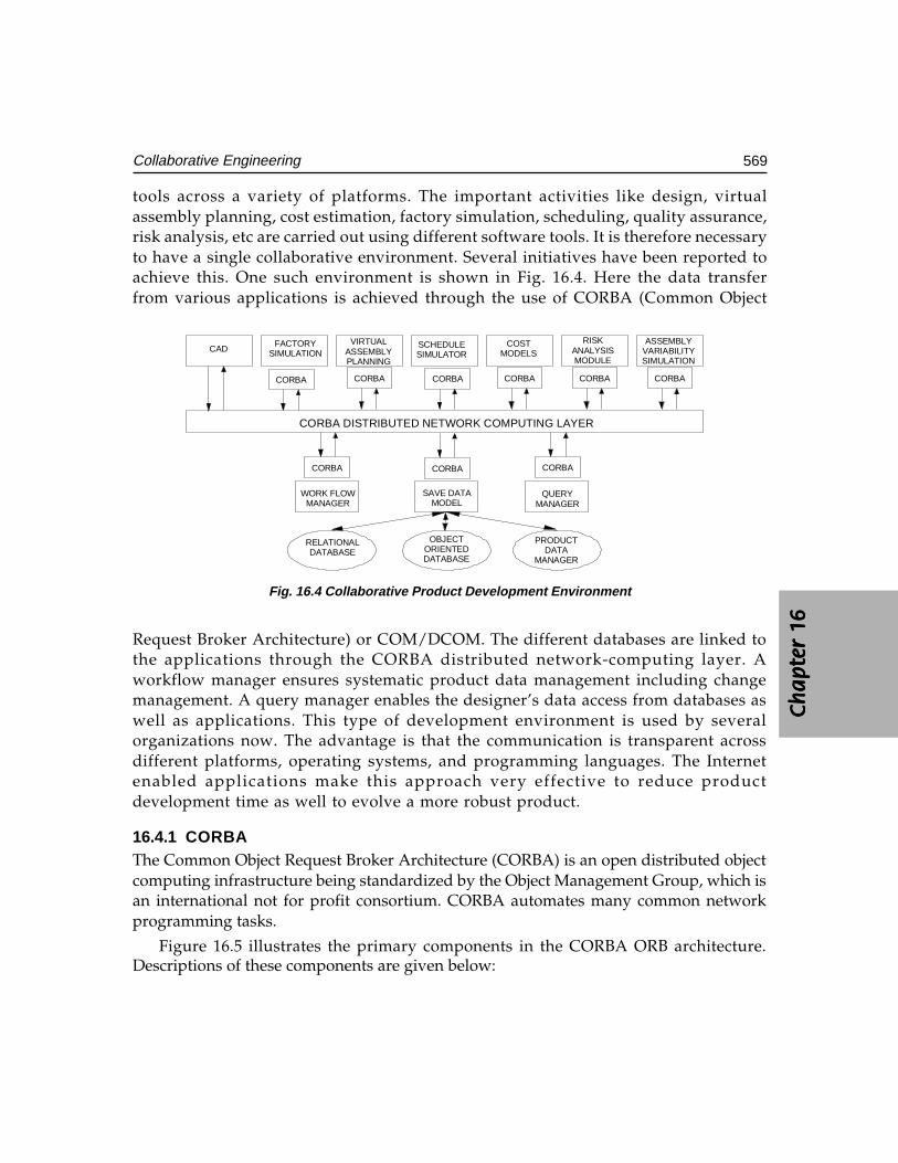
Ch
ap
ter
16C
ha
pte
r 16
Ch
ap
ter
16C
ha
pte
r 16
Ch
ap
ter
16
569Collaborative Engineering
tools across a variety of platforms. The important activities like design, virtualassembly planning, cost estimation, factory simulation, scheduling, quality assurance,risk analysis, etc are carried out using different software tools. It is therefore necessaryto have a single collaborative environment. Several initiatives have been reported toachieve this. One such environment is shown in Fig. 16.4. Here the data transferfrom various applications is achieved through the use of CORBA (Common Object
Request Broker Architecture) or COM/DCOM. The different databases are linked tothe applications through the CORBA distributed network-computing layer. Aworkflow manager ensures systematic product data management including changemanagement. A query manager enables the designer’s data access from databases aswell as applications. This type of development environment is used by severalorganizations now. The advantage is that the communication is transparent acrossdifferent platforms, operating systems, and programming languages. The Internetenabled applications make this approach very effective to reduce productdevelopment time as well to evolve a more robust product.
16.4.1 CORBAThe Common Object Request Broker Architecture (CORBA) is an open distributed objectcomputing infrastructure being standardized by the Object Management Group, which isan international not for profit consortium. CORBA automates many common networkprogramming tasks.
Figure 16.5 illustrates the primary components in the CORBA ORB architecture.Descriptions of these components are given below:
CADFACTORY
SIMULATIONVIRTUAL
ASSEMBLYPLANNING
SCHEDULESIMULATOR
COSTMODELS
RISKANALYSISMODULE
ASSEMBLYVARIABILITYSIMULATION
CORBA CORBA CORBA CORBA CORBA CORBA
CORBA DISTRIBUTED NETWORK COMPUTING LAYER
CORBA CORBA CORBA
WORK FLOWMANAGER
SAVE DATAMODEL
QUERYMANAGER
OBJECTORIENTEDDATABASE
PRODUCTDATA
MANAGER
RELATIONALDATABASE
Fig. 16.4 Collaborative Product Development Environment
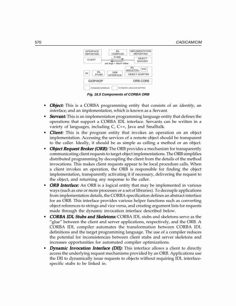
570 CAD/CAM/CIM
INTERFACEREPORTING
IDLCOMPILER
IMPLEMENTATIONREPORTING
CLIENT OBJECTSERVANT
in args
out args + return value
DIIIDL
STUBSORB
INTERFACE OBJECT ADAPTER
DSIIDLSKELETON
GIOP/IIOP ORB CORE
STANDARD INTERFACE STANDARD LANGUAGE MAPPING
Fig. 16.5 Components of CORBA ORB
• Object:Object:Object:Object:Object: This is a CORBA programming entity that consists of an identity, aninterface, and an implementation, which is known as a Servant.
• Servant:Servant:Servant:Servant:Servant: This is an implementation programming language entity that defines theoperations that support a CORBA IDL interface. Servants can be written in avariety of languages, including C, C++, Java and Smalltalk.
• Client: Client: Client: Client: Client: This is the program entity that invokes an operation on an objectimplementation. Accessing the services of a remote object should be transparentto the caller. Ideally, it should be as simple as calling a method or an object.
• Object Request Broker (ORB):Object Request Broker (ORB):Object Request Broker (ORB):Object Request Broker (ORB):Object Request Broker (ORB): The ORB provides a mechanism for transparentlycommunicating client requests to target object implementations. The ORB simplifiesdistributed programming by decoupling the client from the details of the methodinvocations. This makes client requests appear to be local procedure calls. Whena client invokes an operation, the ORB is responsible for finding the objectimplementation, transparently activating it if necessary, delivering the request tothe object, and returning any response to the caller.
• ORB Interface:ORB Interface:ORB Interface:ORB Interface:ORB Interface: An ORB is a logical entity that may be implemented in variousways (such as one or more processes or a set of libraries). To decouple applicationsfrom implementation details, the CORBA specification defines an abstract interfacefor an ORB. This interface provides various helper functions such as convertingobject references to strings and vice versa, and creating argument lists for requestsmade through the dynamic invocation interface described below.
• CORBA IDL Stubs and Skeletons:CORBA IDL Stubs and Skeletons:CORBA IDL Stubs and Skeletons:CORBA IDL Stubs and Skeletons:CORBA IDL Stubs and Skeletons: CORBA IDL stubs and skeletons serve as the“glue” between the client and server applications, respectively, and the ORB. ACORBA IDL compiler automates the transformation between CORBA IDLdefinitions and the target programming language. The use of a compiler reducesthe potential for inconsistencies between client stubs and server skeletons andincreases opportunities for automated compiler optimizations.
• Dynamic Invocation Interface (DII):Dynamic Invocation Interface (DII):Dynamic Invocation Interface (DII):Dynamic Invocation Interface (DII):Dynamic Invocation Interface (DII): This interface allows a client to directlyaccess the underlying request mechanisms provided by an ORB. Applications usethe DII to dynamically issue requests to objects without requiring IDL interface-specific stubs to be linked in.
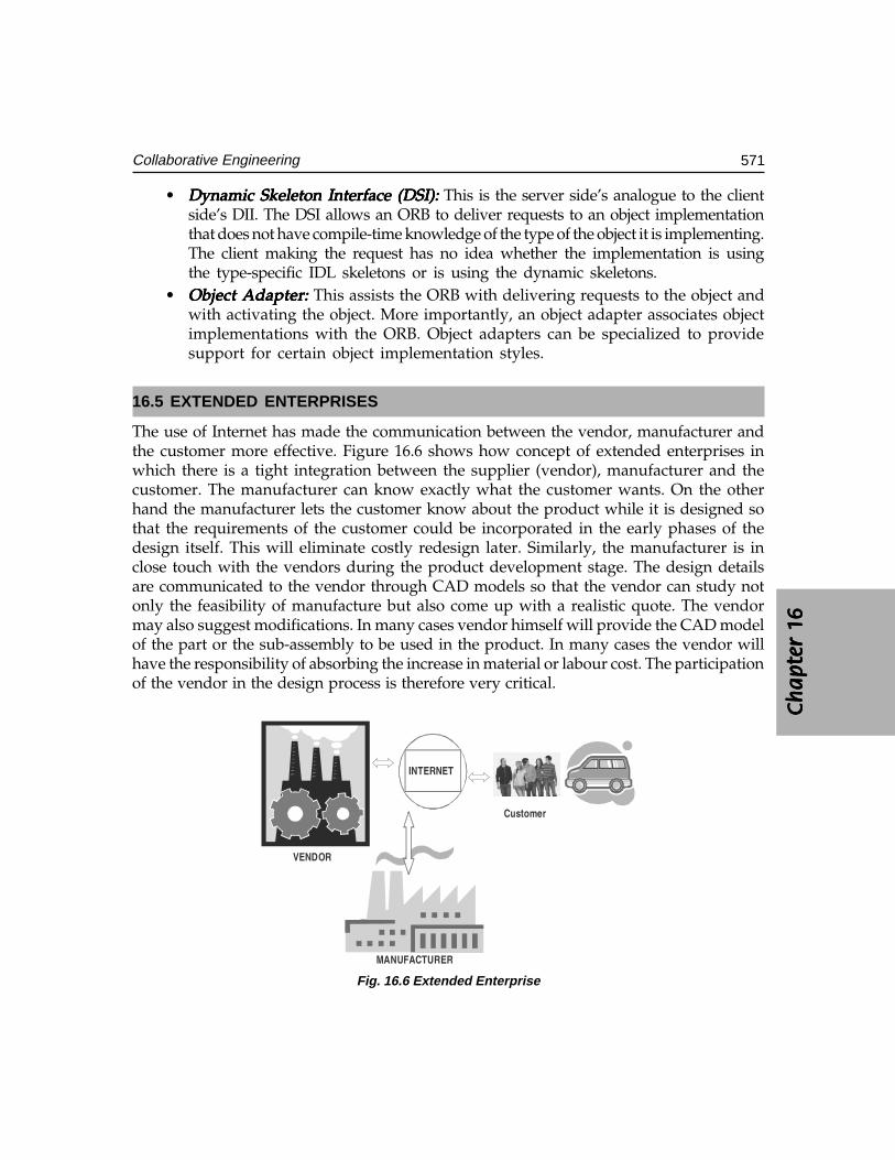
Ch
ap
ter
16C
ha
pte
r 16
Ch
ap
ter
16C
ha
pte
r 16
Ch
ap
ter
16
571Collaborative Engineering
• Dynamic Skeleton Interface (DSI):Dynamic Skeleton Interface (DSI):Dynamic Skeleton Interface (DSI):Dynamic Skeleton Interface (DSI):Dynamic Skeleton Interface (DSI): This is the server side’s analogue to the clientside’s DII. The DSI allows an ORB to deliver requests to an object implementationthat does not have compile-time knowledge of the type of the object it is implementing.The client making the request has no idea whether the implementation is usingthe type-specific IDL skeletons or is using the dynamic skeletons.
• Object Adapter:Object Adapter:Object Adapter:Object Adapter:Object Adapter: This assists the ORB with delivering requests to the object andwith activating the object. More importantly, an object adapter associates objectimplementations with the ORB. Object adapters can be specialized to providesupport for certain object implementation styles.
16.5 EXTENDED ENTERPRISES
The use of Internet has made the communication between the vendor, manufacturer andthe customer more effective. Figure 16.6 shows how concept of extended enterprises inwhich there is a tight integration between the supplier (vendor), manufacturer and thecustomer. The manufacturer can know exactly what the customer wants. On the otherhand the manufacturer lets the customer know about the product while it is designed sothat the requirements of the customer could be incorporated in the early phases of thedesign itself. This will eliminate costly redesign later. Similarly, the manufacturer is inclose touch with the vendors during the product development stage. The design detailsare communicated to the vendor through CAD models so that the vendor can study notonly the feasibility of manufacture but also come up with a realistic quote. The vendormay also suggest modifications. In many cases vendor himself will provide the CAD modelof the part or the sub-assembly to be used in the product. In many cases the vendor willhave the responsibility of absorbing the increase in material or labour cost. The participationof the vendor in the design process is therefore very critical.
��������
������
��� �����
��������
Fig. 16.6 Extended Enterprise
572 CAD/CAM/CIM
16.6 SOFTWARE FOR COLLABORATIVE DESIGN AND ENTERPRISE-WIDEPRODUCT VISUALIZATION
Many CAD/CAM packages provide facilities for collaborative design.
Dassault System’s Component Application Architecture (CAA V5) provides the IXSPeeD V5 suite, making it a natively interoperable and collaborative solution for theCATIA(R) V5. This new product suite includes add-on modules for specialized designrequirements to address an extended product development cycle. With IX SPeeD V5,companies manufacturing consumer goods, electronics and electrical (E&E) can takeadvantage of the power and flexibility of its functional design approach. This powerand flexibility is derived from ImpactXoft’s innovative method of capturing the designbehavior as functional features. This makes it easier to create, interpret, edit and reusedesigns across the extended enterprise. A feature of the Dassault System’s software isthe instant participation feature for collaborative design within the CAA V5 environment.Instant participation’s collaborative capabilities allow OEMs and suppliers to not onlycommunicate design changes, but also to share and merge elements of their productdesigns at anytime, from anywhere, and with anyone working on the project. Functionalmodeling and simultaneous product development approach to solving design problemswithin a global development environment raises the bar for innovative 3D design andcollaboration capabilities.
Collaboration can be synchronous or asynchronous. A synchronous collaborativeCAD solution is usually hosted on an application server provider (ASP) form. CoCreate’sOneSpace is the first such application to appear. PTC’s Pro/Collaborate providesasynchronous collaborative capability. Some of the other software for collaborative designinclude Teamcenter, Cimatron, Fullscope and Matrix One.
Another typical example of collaborative design is that of Swedish automobilemanufacturer Volvo. Volvo’s collaborative design system was built using CentricInnovation software from San Jose-based Centric Software Inc. The software is integratedwith Volvo’s computer-aided design and manufacturing (CAD/CAM) systems and is usedto evaluate alternative vehicle designs and conduct project reviews online, as opposed tobuilding physical mock-ups of prospective vehicles. The system tracks design changesand notify engineers whose specifications are affected by those alterations. The Centricsystem will also help tackle the complex challenge of pulling data from different CAD/CAM systems and then updating those changes across the systems. Volvo currently usesthree different types of CAD/CAM systems for different phases of the vehicle conceptualdesign process.
Digital manufacturing systems with advanced 3-D simulation, virtual reality, andcollaborative product lifecycle management (PLM) software tools are helpingmanufacturers accelerate the design and build cycles of new products, while loweringproduction costs and boosting plant efficiencies.
With digital manufacturing solutions, several manufacturers in aerospace and
Ch
ap
ter
16C
ha
pte
r 16
Ch
ap
ter
16C
ha
pte
r 16
Ch
ap
ter
16
573Collaborative Engineering
automotive have implemented cutting-edge virtual factory systems that allow greaterre-use of engineering data, better control of late engineering changes in the design cycle,and more sophisticated simulations of NC machining processes and factory-floor layouts.
As far as aircraft industry is concerned, Boeing 777 is said to be one of the earliestprojects that was done as a fully digital mockup. With the 787, Boeing is trying to go to acomplete PLM environment using CATIA for design, Enovia for data management andlifecycle management, and Delmia for the manufacturing applications. Lockheed MartinAeronautics Co. also has used digital manufacturing in its Joint Strike Fighter (JSF) program.It is deploying Delmia’s simulation software to assist in analyzing its abilities to produceand support the aircraft. Lockheed Martin uses Delmia simulation tools to identify potentialcollisions in machinery, tooling, and fixtures at the tightly packed, assembly plant in FortWorth, Texas where the planes will be built. Engineers are using the tools to determineaccessibility of spaces inside the airframe and workflow of parts and people with Delmia’sErgo human simulation software that analyzes ergonomic issues.
With collaborative 3-D modeling and simulation, software solutions like Delmia andTecnomatix provide a data model beneath all the applications, which ensures all the dataentered in any one of those disciplines is made available for the other applications to enhanceand leverage the data. This facilitates different team in creating and optimizing their sets ofdata. The customers and vendors also need not search for the most accurate, up-to-date data.This kind of a collaborative environment provides data that are always accurate, current andaccessible. Thus manufacturers can leverage data collaborations in CAD, machining datawith CAM systems, and 3-D simulations on the factory floor and in factory process planning.
Enterprise-wide product development may involve the use of software packages ondiverse platforms and different database software packages. To leverage their investmentin the design and database technology, more and more large manufacturing companiesare using visualization.
The reduction of product development time necessitates that all members of a designteam must be capable of visualizing the product as it is being evolved. Team membersmay be designers within the company or from the vendors. Many will be using differentsoftware packages. The visualization software enables the users to easily view, analyze,and collaborate on complex visual products in a single visual environment. Viewing productinformation in context with the complete visual model is critical to improve communicationacross all departments of a company. Users can interact with a complete product- whetherit is a passenger car, airplane or a machine tool or zoom in on a single small part anddetermine its associated design, manufacturing, and cost or supplier information. Usingstandard Web browser and simulation software, engineers and designers from around theworld can quickly access the latest product databases to interactively view large models ina single visual environment. The real time collaboration capabilities of these softwaresbring designers together in one interactive session, enabling them to quickly identify andresolve issues before costly redevelopment efforts are necessary. This collaboration isalso an effective way to present and review the products with customers and suppliers.

574 CAD/CAM/CIM
QUESTIONS
1. Discuss how Internet is an enabling tool for collaborative product development.2. Describe how World Wide Web can help to shorten the product development
cycle time.3. What are the benefits of collaborative product development?4. Discuss the significance of enterprise wide product visualization.
����������������
���� �
The need for portability of the geometric model among different hardware platforms has ledto the development of device independent graphics. Simultaneously standards for theexchange of drawing database among software packages have been evolved to facilitatethe integration of design and manufacturing operations.
17.1 INTRODUCTION
The heart of any CAD model is the component database. This includes the graphicsentities like points, lines, arcs, circles etc. and the co-ordinate points, which define thelocation of these entities. This geometric data is used in all downstream applications ofCAD, which include finite element modeling and analysis, process planning, estimation,CNC programming, robot programming, programming of co-ordinate measuringmachines, ERP system programming and simulation.
In order to achieve at least a reasonably high level of integration between CAD,analysis and manufacturing operations, the component database must contain:
i. Shapes of the components (based on solid models)ii. Bill of materials (BOM), of the assembly in which the components are used.
iii. Material of the componentsiv. Manufacturing, test and assembly procedures to be carried out to produce a
component so that it is capable of functioning as per the requirements of design.
In designing a data structure for CAD database the following factors are to be considered:
i. The data must be neutralii. The data structure must be user-friendly
iii. The data must be portable.
In order to achieve the above requirements, some type of standardization has to befollowed by the CAD software designers. The basic elements associated with a CADsystem are:
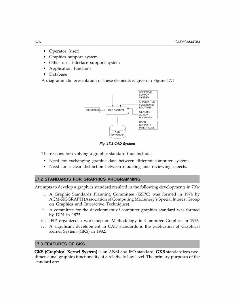
576 CAD/CAM/CIM
• Operator (user)• Graphics support system• Other user interface support system• Application functions• Database
A diagrammatic presentation of these elements is given in Figure 17.1
DESIGNER CAD SYSTEM
GRAPHICS SUPPORTSYSTEM
APPLICATION FUNCTIONS/ROUTINES
GENERICACTIONROUTINES
USERSUPPORTINTERFACES
CADDATABASE
Fig. 17.1 CAD System
The reasons for evolving a graphic standard thus include:
• Need for exchanging graphic data between different computer systems.• Need for a clear distinction between modeling and reviewing aspects.
17.2 STANDARDS FOR GRAPHICS PROGRAMMING
Attempts to develop a graphics standard resulted in the following developments in 70’s:
i. A Graphic Standards Planning Committee (GSPC) was formed in 1974 byACM-SIGGRAPH (Association of Computing Machinery’s Special Interest Groupon Graphics and Interactive Techniques).
ii. A committee for the development of computer graphics standard was formedby DIN in 1975.
iii. IFIP organized a workshop on Methodology in Computer Graphics in 1976.iv. A significant development in CAD standards is the publication of Graphical
Kernel System (GKS) in 1982.
17.3 FEATURES OF GKS
GKS (Graphical Kernel System)GKS (Graphical Kernel System)GKS (Graphical Kernel System)GKS (Graphical Kernel System)GKS (Graphical Kernel System) is an ANSI and ISO standard. GKSGKSGKSGKSGKS standardizes two-dimensional graphics functionality at a relatively low level. The primary purposes of thestandard are:
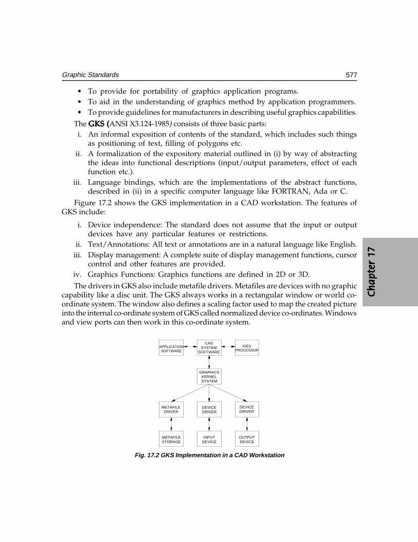
Ch
ap
ter
17C
ha
pte
r 17
Ch
ap
ter
17C
ha
pte
r 17
Ch
ap
ter
17
577Graphic Standards
• To provide for portability of graphics application programs.• To aid in the understanding of graphics method by application programmers.• To provide guidelines for manufacturers in describing useful graphics capabilities.
The GKS (GKS (GKS (GKS (GKS (ANSI X3.124-1985) consists of three basic parts:i. An informal exposition of contents of the standard, which includes such things
as positioning of text, filling of polygons etc.ii. A formalization of the expository material outlined in (i) by way of abstracting
the ideas into functional descriptions (input/output parameters, effect of eachfunction etc.).
iii. Language bindings, which are the implementations of the abstract functions,described in (ii) in a specific computer language like FORTRAN, Ada or C.
Figure 17.2 shows the GKS implementation in a CAD workstation. The features ofGKS include:
i. Device independence: The standard does not assume that the input or outputdevices have any particular features or restrictions.
ii. Text/Annotations: All text or annotations are in a natural language like English.iii. Display management: A complete suite of display management functions, cursor
control and other features are provided.iv. Graphics Functions: Graphics functions are defined in 2D or 3D.
The drivers in GKS also include metafile drivers. Metafiles are devices with no graphiccapability like a disc unit. The GKS always works in a rectangular window or world co-ordinate system. The window also defines a scaling factor used to map the created pictureinto the internal co-ordinate system of GKS called normalized device co-ordinates. Windowsand view ports can then work in this co-ordinate system.
APPLICATIONSOFTWARE
CADSYSTEM
SOFTWARE
IGESPROCESSOR
GRAPHICSKERNELSYSTEM
METAFILEDRIVER
DEVICEDRIVER
DEVICEDRIVER
METAFILESTORAGE
INPUTDEVICE
OUTPUTDEVICE
Fig. 17.2 GKS Implementation in a CAD Workstation
578 CAD/CAM/CIM
GKS offers two routines to define the user created pictures. They are primitivefunctions and attribute functions. Examples of primitive functions are:
• POLYLINE to draw a set of connected straight-line vectors• POLYMARKER to draw a set of markers or shapes• FILL AREA to draw a closed polygon with interior fill• TEXT to create characters• GDP (Generalized Drawing Primitive) to specify the standard drawing entities
like circle, ellipse etc.
The attribute functions define the appearance of the image e.g. color, line-type etc.Current level of GKS is GKS-3D, which provides several other functions. GKS-3D is anextension to GKS, which allows the production of 3-D objects.
17.4 OTHER GRAPHICS STANDARDS
The Graphics Standards Planning Committee (GSPC) of ACM-SIGGRAPH proposedthe CORE system in 1977 and revised it in 1979. Though the development of GKS hasbeen influenced by the CORE system, there are a number of significant differencesbetween the two. However, the core graphics have a number of problems at the level ofprogram portability. From a technological point of view, the GSPC CORE has beeneclipsed by the development in GKS.
17.5 PHIGS
PHIGS (Programmer’s Hierarchical Interactive Graphics Standard) includes in itsfunctionality three dimensional output primitives and transformations. It has dynamiccontrol over the visual appearance of attributes of primitives in a segment. The PHIGSstandard defines a set of device-independent logical concepts. Application programmerscan use these concepts within a set of PHIGS rules. The major concepts are the LogicalInput Device, PHIGS structure, Structure Networks, Structure Manipulation, Search andInquiry, Structure Traversal and Display, the Name Set mechanism, the viewing pipeline,and the PHIGS workstation.
PHIGS, a programming library for 3D graphics, was developed and maintained byISO. It is most commonly used on the X Windows system. The PHIGS high level graphicslibrary contains over 400 functions ranging from simple line drawing to lighting andshading. Before displaying a picture, the application first stores its graphics informationin the PHIGS graphic database. Therefore PHIGS is referred to as a display list system.The application then appears on one or more display devices and then passes the listto them.
Ch
ap
ter
17C
ha
pte
r 17
Ch
ap
ter
17C
ha
pte
r 17
Ch
ap
ter
17
579Graphic Standards
17.5.1 STRUCTURE NETWORKSStructure networks are formed through a relation among various structures in thecentralized structure store (CSS). Structure networks are hierarchical and acyclic. This meansthat structure networks are formed through invocations of other structures in the CSS.
17.5.2 LOGICAL INPUT DEVICESPHIGS allows graphics input for applications programs via six classes of logical inputdevices, each of which delivers graphics data. These are listed below:
Locator : returns a point in world co-ordinates.Stroke : returns a list of points the work coordinates.Valuator : returns a real value in a settable range.Choice : returns an integer between 1 and a certain value nString : returns a character string.Hierarchical pick : returns a reference to a picked primitive.
These conceptual devices are not linked to specific hardware. i.e., the same tablet canbe used to realize different devices such as locator and a hierarchical pick. All of thesedevices are similar to those of Graphics Kernel System (GKS) except for the hierarchicalpick. This is unique to PHIGS.
17.5.3 STRUCTURE MANIPULATIONA structure can be deleted invoking a function called DELETE STRUCTURE. Once thisfunction has been executed the entire structure is wiped out from the CSS. Another functionDELETE STRUCTURE NETWORK wipes out the whole structure network from the pointit has been referenced.
17.5.4 SEARCH AND ENQUIRYPHIGS has functionalities for interrogating the CSS for determining the element contentsand its characteristics. The complete details of a specified structure element can bedetermined by calling functions like INQUIRE ELEMENT TYPE AND SIZE and INQUIREELEMENT CONTENT. Functions such as INQUIRE PATHS TO ANCESTORS andINQUIRE PATHS TO DESCENDANTS can determine the relationship of a structure toother structures in the CSS. The ELEMENT SEARCH function allows searching within astructure for a particular element type or one of a set of element types. The INCREMENTALSPATIAL SEARCH (ISS) allows a structure network to be searched for the next occurrenceof a graphical output structure element, which satisfies the specified search criteria. Searchpaths do the referencing of the start-point and found-point.
17.5.5 STRUCTURE ARCHIVAL AND RETRIEVALAn archive file is a medium for storing structure definitions.
580 CAD/CAM/CIM
Functions like ARCHIVE STRUCTURES (or STRUCTURE NETWORKS), RETRIEVESTRUCTURES (or STRUCTURE NETWORKS), DELETE STRUCTURES (or STRUCTURENETWORKS), etc. are available in PHIGS for archiving structures (or its networks) into an‘archive file’ from the CSS, or retrieving it from the file itself, respectively. The relationshipof a structure with other structures is determined by the path functions.
17.5.6 STRUCTURE TRAVERSAL AND DISPLAYTraversal is an operation used to describe a method of structure element processing. Thetraversal of a network leads to the display of graphical output from the structure networkat each workstation to which it is posted. The traversal process interprets each structureelement in the structure network sequentially starting at the first element at the top of thenetwork. Any change to the posted structure network triggers a re-traversal of the structurenetwork so that the changes are processed immediately.
17.5.7 GRAPHICAL OUTPUTThe graphical output of PHIGS is built up from ‘output primitives’ and ‘primitive attributes’.Output primitives are generated from structure elements by structure traversal. Arepresentative cross-section of these are: Polyline, Polymarker, Text, Fill Area, Fill AreaSet, Cell Array, Generalized Drawing Primitive (GDP), B-splines, and NURBS. Text, FillArea, Fill Area Set, and Cell Array are ‘planar primitives’ in arbitrary planes. Conceptuallythese planes have two sides and zero thickness. The viewing transformation determineswhich side of these primitives is seen.
The discussion on the GKS and PHIGS is to make the reader aware of the developmentsthat led to the present status of computer graphics. The popularity of Open GL has nowmade GKS obsolete.
17.6 OPENGL
Silicon Graphics (SGI) developed the OpenGL application-programming interface (API)for the development of 2D and 3D graphics applications. It is a low-level vendor-neutralsoftware interface. It is often referred to as the assembler language of computer graphics.It provides enormous flexibility and functionality. It is used on a variety of platforms.
OpenGL is a low-level graphics library specification. OpenGL makes available to theprogrammer a small set of geometric primitives - points, lines, polygons, images, andbitmaps. OpenGL provides a set of commands that allow the specification of geometricobjects in two or three dimensions, using the provided primitives, together with commandsthat control how these objects are rendered into the frame buffer.
The OpenGL API was designed for use with the C and C++ programming languagesbut there are also bindings for a number of other programming languages such as Java,Ada, and FORTRAN. OpenGL provides primitives for modelling in 3D. Its capabilities
Ch
ap
ter
17C
ha
pte
r 17
Ch
ap
ter
17C
ha
pte
r 17
Ch
ap
ter
17
581Graphic Standards
include viewing and modelling transformation, viewport transformation, projections(orthographic and perspective), animation, lighting etc.
17.7 PARASOLID
Most high-end CAD/CAM systems have their proprietary geometric modeler embeddedwithin the modeling application. Parasolid is a portable “kernel” that can be used inmultiple systems - both high-end and mid-range. In the early 1990s a number of softwaredevelopers decided to adopt Parasolid. By adopting Parasolid, start-up softwarecompanies have eliminated a major barrier to application development - a high initialinvestment. This enabled them to effectively market softwares with strong solid modelingfunctionality at lower-cost.
Today Parasolid is used as component software in many of the world’s leading CAD/CAM systems. Unigraphics and Solid Edge, Parametric Technology, Solid WorksCorporation ANSYS, Mechanical Dynamics, McNeal-Schwendler and Bentley systemsare today using Parasolid. Companies such as Boeing, Israel Aircraft Industries andMitsubishi Motors use Parasolid for internal development.
17.7.1 MODELING FUNCTIONALITIES OF PARASOLIDParasolid’s modeling abilities include:
(i) Complex Blending:Complex Blending:Complex Blending:Complex Blending:Complex Blending: Parasolid provides excellent functionality of blending edgesand faces. The functions include, rolling ball, variable, face-face, cliff-edge,overlapping, overflowing, continuous, tangent hold line, disc and conic sectionand conic hold line.
(ii) Hollowing, Shelling, Offsetting and Thickening Surfaces:Hollowing, Shelling, Offsetting and Thickening Surfaces:Hollowing, Shelling, Offsetting and Thickening Surfaces:Hollowing, Shelling, Offsetting and Thickening Surfaces:Hollowing, Shelling, Offsetting and Thickening Surfaces: These are methods forcreating thin-walled parts, which are very common in many industries. To theCAD/CAM user, these are conceptually simple, but the topological changesrequired are a rigorous test of modeler reliability.
(iii) Tapering and Draft Angles:Tapering and Draft Angles:Tapering and Draft Angles:Tapering and Draft Angles:Tapering and Draft Angles: These operations are used primarily for mold anddie design. Parasolid can apply taper to complex designs following complexparting lines. Non-uniform scaling is another useful feature.
(iv) Complex Modeling Using B-Surfaces:Complex Modeling Using B-Surfaces:Complex Modeling Using B-Surfaces:Complex Modeling Using B-Surfaces:Complex Modeling Using B-Surfaces: These are methods for creating thin-walled parts, which are very common in many industries. To the CAD/CAMuser these are conceptually simple, but the topological changes required are arigorous test of modeler reliability.
(v) Tolerant Modeling and B-rep Import Tools:Tolerant Modeling and B-rep Import Tools:Tolerant Modeling and B-rep Import Tools:Tolerant Modeling and B-rep Import Tools:Tolerant Modeling and B-rep Import Tools: Parasolid’s Tolerant Modelingtechnology helps to import geometry, particularly trimmed surfaces from othermodelers even when they are less accurate. Parasolid can apply differenttolerances to each entity to accommodate anomalies in imported geometry.When improved trimmed surfaces do not fit exactly to Parasolid’s high accuracy,
582 CAD/CAM/CIM
the surfaces can be sewn together by asking Parasolid to calculate appropriatetolerances to optimize performance and reliability.
In a nutshell, Parasolid incorporates object-oriented routines needed to create reallife, complex models great accuracy, reliability and speed. Some of the functionalities inParasolid are:
• Creation of solid primitives: blocks, cones, cylinders, tori, and spheres• Creation of solids using swept and spun profiles• Creation of solids by sewing and knitting of trimmed surfaces• NURBS curves and surfaces as well as analytical curves and surfaces• Non-manifold, cellular and mixed dimension topologies• feature modeling applications through Booleans and instancing• Complex blending and chamfering• Non-uniform scaling• Tolerant Modeling enables reliable modeling with imported data• Geometry and topology inquiries• Interference detection and clearance calculations• Calculation of mass and inertia properties• Foreign geometry interface to allow import from proprietary geometric systems• Full range of geometric output formats including trimmed surface• Graphical data output for wire-frame, silhouettes, hidden line and faceting
17.7.2 APPLICATIONS
(i) Computer Aided Design:Computer Aided Design:Computer Aided Design:Computer Aided Design:Computer Aided Design: CAD systems create mathematical models based on userinput. Individual models can then be combined as components of an assemblyto create a product. Parasolid adds value by being able to model real life objectsmore accurately and more reliably.
(ii) Computer Aided Engineering:Computer Aided Engineering:Computer Aided Engineering:Computer Aided Engineering:Computer Aided Engineering: CAE systems analyze designs created by CADsystems by calculating stress, applying the principles of thermodynamics, vibration,mechanisms, acoustics, aerodynamics and electromagnetism. Analyzing, makingdesign changes and re-analyzing optimize a design.
(iii) Computer Aided Manufacturing:Computer Aided Manufacturing:Computer Aided Manufacturing:Computer Aided Manufacturing:Computer Aided Manufacturing: CAM systems generate programs for CNCmachine tools to manufacture a component. CAM covers every type of machiningprocess from simple turning on a lathe to 5 axes milling of complex surfaces.Parasolid adds value by permitting the import of models from many Parasolid-based CAD systems and the interrogation of the geometry and topology.
(iv) Translators:Translators:Translators:Translators:Translators: Parasolid is capable of accepting data from other modeler formats.Its unique Tolerant Modeling functionality can accommodate and compensate forless accurate data.
Ch
ap
ter
17C
ha
pte
r 17
Ch
ap
ter
17C
ha
pte
r 17
Ch
ap
ter
17
583Graphic Standards
17.8 ACIS
ACIS is another object oriented three-dimensional geometric modeling engine. It isdesigned for use as the geometry foundation in a 3D modeling application.
ACIS is written in C++ and consists of a set of C++ classes and functions. A developeruses these classes and functions to create an end user 3D application. ACIS complementsexisting applications by offering a unified environment for the modeling of curves, surfacesand solids. ACIS provides a foundation of common modeling functionality and flexibilityto be adapted and extended for particular application requirements.
ACIS integrates wire frame, surface and solid modeling by allowing these alternativerepresentations to coexist naturally in a unified data structure, which is implemented in ahierarchy of C++ classes. ACIS bodies can have any of these forms or combinations ofthem. Linear and quadratic geometry is represented analytically and non-uniform rationalB-Splines represent free-form geometry. ACIS is a boundary-representation (B-rep) modeler,which means that it defines the boundary between solid material and empty space. Thisboundary is made from a closed set of surfaces.
17.8.1 ACIS ARCHITECTUREThe ACIS has been designed using software component technology. A ‘softwarecomponent’ is a functionally specialized unit of software - a collection of software items(functions, classes, etc.) grouped together to serve some distinct purpose. It serves as aconstituent part of a whole software system or product. A ‘product’ is one or moresoftware components that are assembled together and sold as a package. Componentscan be arranged in different combinations to form different products.
Some of the ACIS components are:Some of the ACIS components are:Some of the ACIS components are:Some of the ACIS components are:Some of the ACIS components are:Advanced Blending - Optional husk for blending beyond standard ACIS
blendingAG spline - Spline library and interfaceACISMFC - Support for MFC based applicationsBoolean - Unite, intersect and subtract operationsClearance - Determine minimum distance between bodies or facesConstructors - Basic topology construction; wire frame
construction and editing; analysis (area,length, mass properties)
Cellular Topology - Divide lumps into sets of cellsEuler Operations - Expand, separate and combine lumpsFaceter - Generate faceted (polygonal) representationGeneric Attributes - Attributes that allow applications to exchange dataGraphic Interaction - Commonly needed graphic display functionality
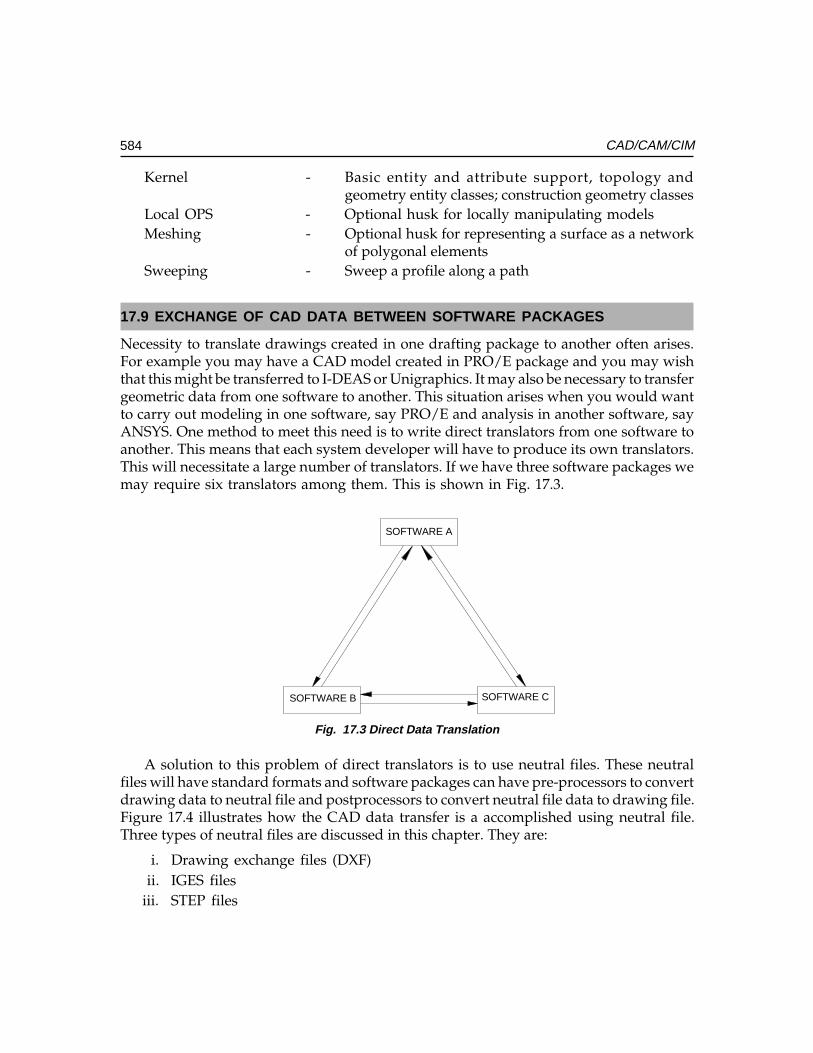
584 CAD/CAM/CIM
Kernel - Basic entity and attribute support, topology andgeometry entity classes; construction geometry classes
Local OPS - Optional husk for locally manipulating modelsMeshing - Optional husk for representing a surface as a network
of polygonal elementsSweeping - Sweep a profile along a path
17.9 EXCHANGE OF CAD DATA BETWEEN SOFTWARE PACKAGES
Necessity to translate drawings created in one drafting package to another often arises.For example you may have a CAD model created in PRO/E package and you may wishthat this might be transferred to I-DEAS or Unigraphics. It may also be necessary to transfergeometric data from one software to another. This situation arises when you would wantto carry out modeling in one software, say PRO/E and analysis in another software, sayANSYS. One method to meet this need is to write direct translators from one software toanother. This means that each system developer will have to produce its own translators.This will necessitate a large number of translators. If we have three software packages wemay require six translators among them. This is shown in Fig. 17.3.
SOFTWARE A
SOFTWARE B SOFTWARE C
Fig. 17.3 Direct Data Translation
A solution to this problem of direct translators is to use neutral files. These neutralfiles will have standard formats and software packages can have pre-processors to convertdrawing data to neutral file and postprocessors to convert neutral file data to drawing file.Figure 17.4 illustrates how the CAD data transfer is a accomplished using neutral file.Three types of neutral files are discussed in this chapter. They are:
i. Drawing exchange files (DXF)ii. IGES files
iii. STEP files
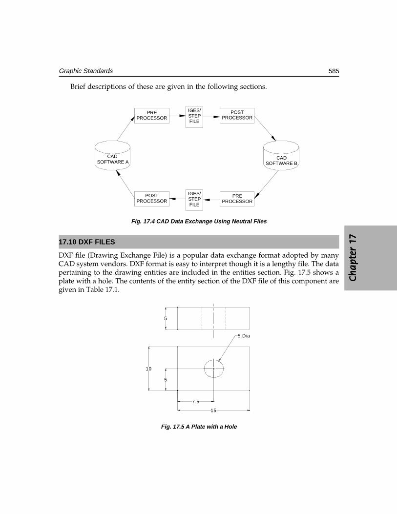
Ch
ap
ter
17C
ha
pte
r 17
Ch
ap
ter
17C
ha
pte
r 17
Ch
ap
ter
17
585Graphic Standards
Brief descriptions of these are given in the following sections.
CAD SOFTWARE A
PREPROCESSOR
POSTPROCESSOR
IGES/STEPFILE
IGES/STEPFILE
POSTPROCESSOR
PREPROCESSOR
CADSOFTWARE B
Fig. 17.4 CAD Data Exchange Using Neutral Files
17.10 DXF FILES
DXF file (Drawing Exchange File) is a popular data exchange format adopted by manyCAD system vendors. DXF format is easy to interpret though it is a lengthy file. The datapertaining to the drawing entities are included in the entities section. Fig. 17.5 shows aplate with a hole. The contents of the entity section of the DXF file of this component aregiven in Table 17.1.
7.5
15
10
5
5 Dia
5
Fig. 17.5 A Plate with a Hole
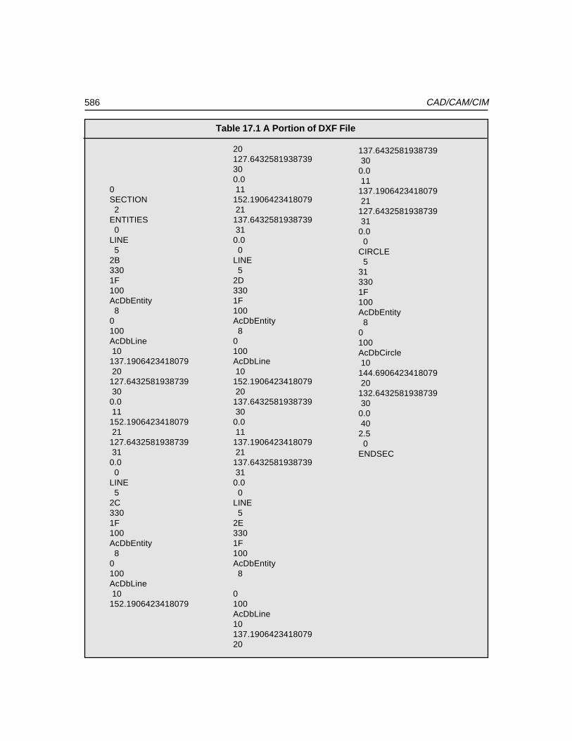
586 CAD/CAM/CIM
Table 17.1 A Portion of DXF File
137.6432581938739 300.0 11137.1906423418079 21127.6432581938739 310.0 0CIRCLE 5313301F100AcDbEntity 80100AcDbCircle 10144.6906423418079 20132.6432581938739 300.0 402.5 0ENDSEC
20127.6432581938739300.0 11152.1906423418079 21137.6432581938739 310.0 0LINE 52D3301F100AcDbEntity 80100AcDbLine 10152.1906423418079 20137.6432581938739 300.0 11137.1906423418079 21137.6432581938739 310.0 0LINE 52E3301F100AcDbEntity 8
0100AcDbLine10137.190642341807920
0SECTION 2ENTITIES 0LINE 52B3301F100AcDbEntity 80100AcDbLine 10137.1906423418079 20127.6432581938739 300.0 11152.1906423418079 21127.6432581938739 310.0 0LINE 52C3301F100AcDbEntity 80100AcDbLine 10152.1906423418079
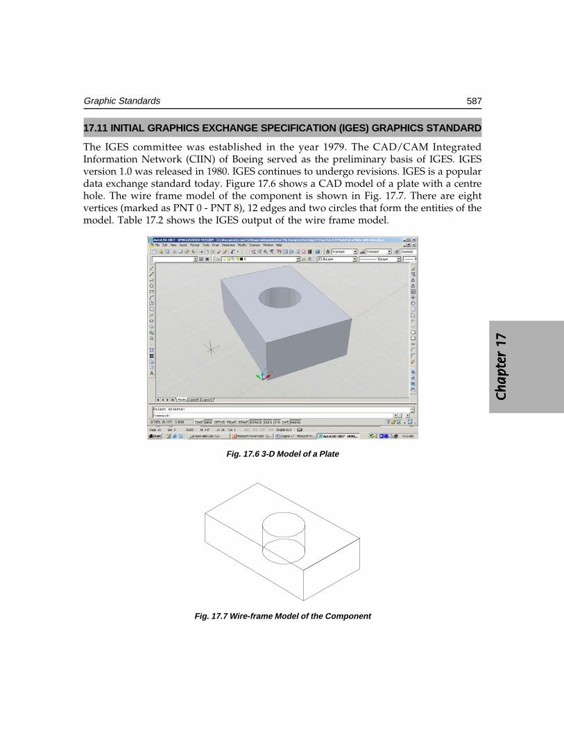
Ch
ap
ter
17C
ha
pte
r 17
Ch
ap
ter
17C
ha
pte
r 17
Ch
ap
ter
17
587Graphic Standards
17.11 INITIAL GRAPHICS EXCHANGE SPECIFICATION (IGES) GRAPHICS STANDARD
The IGES committee was established in the year 1979. The CAD/CAM IntegratedInformation Network (CIIN) of Boeing served as the preliminary basis of IGES. IGESversion 1.0 was released in 1980. IGES continues to undergo revisions. IGES is a populardata exchange standard today. Figure 17.6 shows a CAD model of a plate with a centrehole. The wire frame model of the component is shown in Fig. 17.7. There are eightvertices (marked as PNT 0 - PNT 8), 12 edges and two circles that form the entities of themodel. Table 17.2 shows the IGES output of the wire frame model.
Fig. 17.6 3-D Model of a Plate
Fig. 17.7 Wire-frame Model of the Component
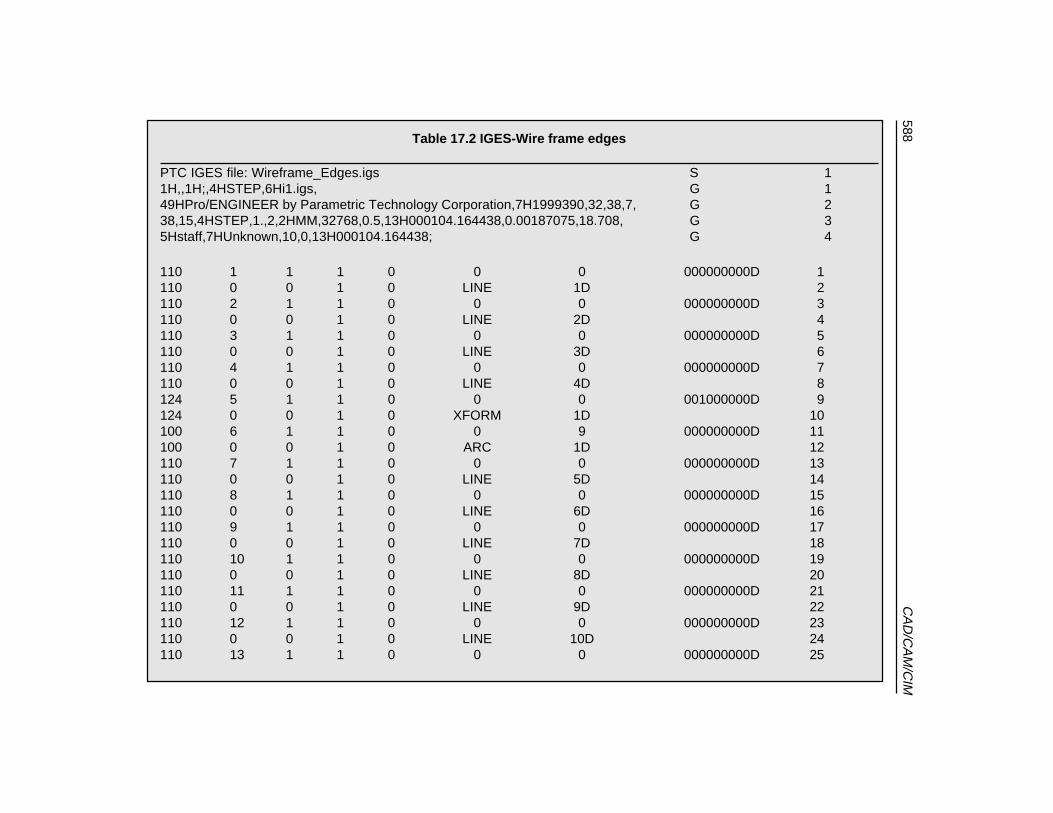
588C
AD
/CA
M/C
IMTable 17.2 IGES-Wire frame edges
PTC IGES file: Wireframe_Edges.igs S 11H,,1H;,4HSTEP,6Hi1.igs, G 149HPro/ENGINEER by Parametric Technology Corporation,7H1999390,32,38,7, G 238,15,4HSTEP,1.,2,2HMM,32768,0.5,13H000104.164438,0.00187075,18.708, G 35Hstaff,7HUnknown,10,0,13H000104.164438; G 4
110 1 1 1 0 0 0 000000000D 1110 0 0 1 0 LINE 1D 2110 2 1 1 0 0 0 000000000D 3110 0 0 1 0 LINE 2D 4110 3 1 1 0 0 0 000000000D 5110 0 0 1 0 LINE 3D 6110 4 1 1 0 0 0 000000000D 7110 0 0 1 0 LINE 4D 8124 5 1 1 0 0 0 001000000D 9124 0 0 1 0 XFORM 1D 10100 6 1 1 0 0 9 000000000D 11100 0 0 1 0 ARC 1D 12110 7 1 1 0 0 0 000000000D 13110 0 0 1 0 LINE 5D 14110 8 1 1 0 0 0 000000000D 15110 0 0 1 0 LINE 6D 16110 9 1 1 0 0 0 000000000D 17110 0 0 1 0 LINE 7D 18110 10 1 1 0 0 0 000000000D 19110 0 0 1 0 LINE 8D 20110 11 1 1 0 0 0 000000000D 21110 0 0 1 0 LINE 9D 22110 12 1 1 0 0 0 000000000D 23110 0 0 1 0 LINE 10D 24110 13 1 1 0 0 0 000000000D 25
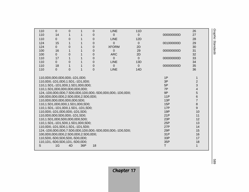
Chapter 17Chapter 17Chapter 17Chapter 17Chapter 17
589G
raphic Standards
110 0 0 1 0 LINE 11D 26110 14 1 1 0 0 0 000000000D 27110 0 0 1 0 LINE 12D 28124 15 1 1 0 0 0 001000000D 29124 0 0 1 0 XFORM 2D 30100 16 1 1 0 0 29 000000000D 31100 0 0 1 0 ARC 2D 32110 17 1 1 0 0 0 000000000D 33110 0 0 1 0 LINE 13D 34110 18 1 1 0 0 0 000000000D 35110 0 0 1 0 LINE 14D 36
110,0D0,0D0,0D0,0D0,-1D1,0D0; 1P 1110,0D0,-1D1,0D0,1.5D1,-1D1,0D0; 3P 2110,1.5D1,-1D1,0D0,1.5D1,0D0,0D0; 5P 3110,1.5D1,0D0,0D0,0D0,0D0,0D0; 7P 4124,-1D0,0D0,0D0,7.5D0,0D0,1D0,0D0,-5D0,0D0,0D0,-1D0,0D0; 9P 5100,0D0,0D0,0D0,2.5D0,0D0,2.5D0,0D0; 11P 6110,0D0,0D0,0D0,0D0,0D0,5D0; 13P 7110,1.5D1,0D0,0D0,1.5D1,0D0,5D0; 15P 8110,1.5D1,-1D1,0D0,1.5D1,-1D1,5D0; 17P 9110,0D0,-1D1,0D0,0D0,-1D1,5D0; 19P 10110,0D0,0D0,5D0,0D0,-1D1,5D0; 21P 11110,1.5D1,0D0,5D0,0D0,0D0,5D0; 23P 12110,1.5D1,-1D1,5D0,1.5D1,0D0,5D0; 25P 13110,0D0,-1D1,5D0,1.5D1,-1D1,5D0; 27P 14124,-1D0,0D0,0D0,7.5D0,0D0,1D0,0D0,-5D0,0D0,0D0,-1D0,5D0; 29P 15100,0D0,0D0,0D0,2.5D0,0D0,2.5D0,0D0; 31P 16110,5D0,-5D0,5D0,5D0,-5D0,0D0; 33P 17110,1D1,-5D0,5D0,1D1,-5D0,0D0; 35P 18S 1G 4D 36P 18 T 1
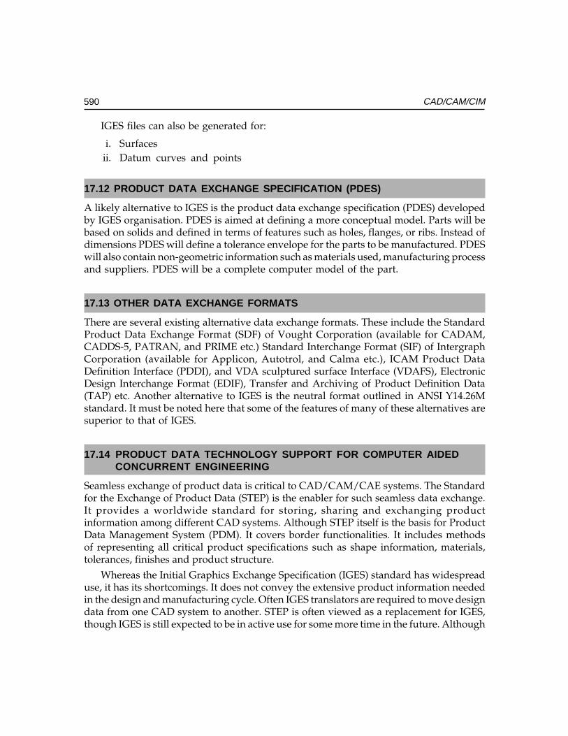
590 CAD/CAM/CIM
IGES files can also be generated for:
i. Surfacesii. Datum curves and points
17.12 PRODUCT DATA EXCHANGE SPECIFICATION (PDES)
A likely alternative to IGES is the product data exchange specification (PDES) developedby IGES organisation. PDES is aimed at defining a more conceptual model. Parts will bebased on solids and defined in terms of features such as holes, flanges, or ribs. Instead ofdimensions PDES will define a tolerance envelope for the parts to be manufactured. PDESwill also contain non-geometric information such as materials used, manufacturing processand suppliers. PDES will be a complete computer model of the part.
17.13 OTHER DATA EXCHANGE FORMATS
There are several existing alternative data exchange formats. These include the StandardProduct Data Exchange Format (SDF) of Vought Corporation (available for CADAM,CADDS-5, PATRAN, and PRIME etc.) Standard Interchange Format (SIF) of IntergraphCorporation (available for Applicon, Autotrol, and Calma etc.), ICAM Product DataDefinition Interface (PDDI), and VDA sculptured surface Interface (VDAFS), ElectronicDesign Interchange Format (EDIF), Transfer and Archiving of Product Definition Data(TAP) etc. Another alternative to IGES is the neutral format outlined in ANSI Y14.26Mstandard. It must be noted here that some of the features of many of these alternatives aresuperior to that of IGES.
17.14 PRODUCT DATA TECHNOLOGY SUPPORT FOR COMPUTER AIDEDCONCURRENT ENGINEERING
Seamless exchange of product data is critical to CAD/CAM/CAE systems. The Standardfor the Exchange of Product Data (STEP) is the enabler for such seamless data exchange.It provides a worldwide standard for storing, sharing and exchanging productinformation among different CAD systems. Although STEP itself is the basis for ProductData Management System (PDM). It covers border functionalities. It includes methodsof representing all critical product specifications such as shape information, materials,tolerances, finishes and product structure.
Whereas the Initial Graphics Exchange Specification (IGES) standard has widespreaduse, it has its shortcomings. It does not convey the extensive product information neededin the design and manufacturing cycle. Often IGES translators are required to move designdata from one CAD system to another. STEP is often viewed as a replacement for IGES,though IGES is still expected to be in active use for some more time in the future. Although
Ch
ap
ter
17C
ha
pte
r 17
Ch
ap
ter
17C
ha
pte
r 17
Ch
ap
ter
17
591Graphic Standards
the current focus of STEP is on mechanical parts, STEP is a data exchange standard thatwould apply to a wide range of product areas, including electronics, architectural,engineering and construction, apparel and shipbuilding.
17.14.1 STEP ARCHITECTURESTEP architecture has four main components:
• EXPRESS modeling language• Data schemes including attributes such as geometry, topology, features and
tolerance.• Aapplication interface called Standard Data Access Interface (SDAI), which
is a standard interface to enable applications to access and manipulate STEPdata
• STEP database, which has the following forms:• ASCII format file for data exchange• Working from file, usually in binary format, that can be shared by multiple
systems• Shared database, involving object oriented database management system or
relational database system• Knowledge base, with a database management system as a base coupled to
an expert shell
17.14.2 STEP ENABLER FOR CONCURRENT ENGINEERINGSTEP was released in early 1993 as a Draft International Standard (DIS). The initial releaseof STEP has four basic parts. These include:
• EXPRESS modeling language• Two application protocols• Drafting and Configuration Control Design for three-dimensional product data.• Six application resources.
Subsequent releases of STEP provided added functionality in terms of the kinds ofproduct supported and the extent of the product life cycle. While STEP is advancing towardsmaturity, it had been investigated for the feasibility of incorporation into framework system.Both STEP and Concurrent Engineering share the common goal of influencing the productcycle from design, assembly, etc. to the disposal stages which have been realized in theCONSENS system under ESPRIT EP6896. The object-oriented database for CONSENShas a schema with STEP definitions alongside company specific definitions. A modulecalled Product Information Archive (PIA) provides functionality for STEP data accessvia SDAI. It is generic to be adopted for different domains.
For example it is used for product information by the Aircraft Company, DeutshcesAerospace and electronics manufacturing company, AEG.

592 CAD/CAM/CIM
STEP data export in a CAD modeling package has the following options:
(i) wire frame edges(ii) surfaces
(iii) solids(iv) shells(v) Datum curves and points
A typical STEP output for the wire frame model shown in Fig. 17.7 is given in Table17.3.
Table 17.3 STEP Output
ISO-10303-21;HEADER;FILE_DESCRIPTION((‘’),’1');FILE_NAME(‘STEP’,’2000-01-04T’,(‘staff’),(‘’),‘PRO/ENGINEER BY PARAMETRIC TECHNOLOGY CORPORATION, 1999390’,‘PRO/ENGINEER BY PARAMETRIC TECHNOLOGY CORPORATION, 1999390’,’’);FILE_SCHEMA((‘CONFIG_CONTROL_DESIGN’));ENDSEC;DATA;#1=DIRECTION(‘’,(0.E0,-1.E0,0.E0));#2=VECTOR(‘’,#1,1.E1);#3=CARTESIAN_POINT(‘’,(0.E0,0.E0,0.E0));#4=LINE(‘’,#3,#2);#6=GEOMETRIC_CURVE_SET(‘’,(#5,#11,#16,#21,#27,#32,#37,#42,#47,#52,#57,#62,#67,#73,#78,#83));#7=DIRECTION(‘’,(1.E0,0.E0,0.E0));#8=VECTOR(‘’,#7,1.5E1);#9=CARTESIAN_POINT(‘’,(0.E0,-1.E1,0.E0));#10=LINE(‘’,#9,#8);#12=DIRECTION(‘’,(0.E0,1.E0,0.E0));#13=VECTOR(‘’,#12,1.E1);#14=CARTESIAN_POINT(‘’,(1.5E1,-1.E1,0.E0));#15=LINE(‘’,#14,#13);#17=DIRECTION(‘’,(-1.E0,0.E0,0.E0));#18=VECTOR(‘’,#17,1.5E1);#19=CARTESIAN_POINT(‘’,(1.5E1,0.E0,0.E0));#20=LINE(‘’,#19,#18);#22=CARTESIAN_POINT(‘’,(7.5E0,-5.E0,0.E0));
Contd....
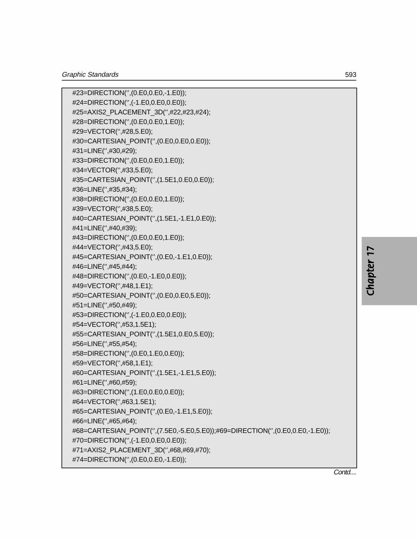
Ch
ap
ter
17C
ha
pte
r 17
Ch
ap
ter
17C
ha
pte
r 17
Ch
ap
ter
17
593Graphic Standards
#23=DIRECTION(‘’,(0.E0,0.E0,-1.E0));#24=DIRECTION(‘’,(-1.E0,0.E0,0.E0));#25=AXIS2_PLACEMENT_3D(‘’,#22,#23,#24);#28=DIRECTION(‘’,(0.E0,0.E0,1.E0));#29=VECTOR(‘’,#28,5.E0);#30=CARTESIAN_POINT(‘’,(0.E0,0.E0,0.E0));#31=LINE(‘’,#30,#29);#33=DIRECTION(‘’,(0.E0,0.E0,1.E0));#34=VECTOR(‘’,#33,5.E0);#35=CARTESIAN_POINT(‘’,(1.5E1,0.E0,0.E0));#36=LINE(‘’,#35,#34);#38=DIRECTION(‘’,(0.E0,0.E0,1.E0));#39=VECTOR(‘’,#38,5.E0);#40=CARTESIAN_POINT(‘’,(1.5E1,-1.E1,0.E0));#41=LINE(‘’,#40,#39);#43=DIRECTION(‘’,(0.E0,0.E0,1.E0));#44=VECTOR(‘’,#43,5.E0);#45=CARTESIAN_POINT(‘’,(0.E0,-1.E1,0.E0));#46=LINE(‘’,#45,#44);#48=DIRECTION(‘’,(0.E0,-1.E0,0.E0));#49=VECTOR(‘’,#48,1.E1);#50=CARTESIAN_POINT(‘’,(0.E0,0.E0,5.E0));#51=LINE(‘’,#50,#49);#53=DIRECTION(‘’,(-1.E0,0.E0,0.E0));#54=VECTOR(‘’,#53,1.5E1);#55=CARTESIAN_POINT(‘’,(1.5E1,0.E0,5.E0));#56=LINE(‘’,#55,#54);#58=DIRECTION(‘’,(0.E0,1.E0,0.E0));#59=VECTOR(‘’,#58,1.E1);#60=CARTESIAN_POINT(‘’,(1.5E1,-1.E1,5.E0));#61=LINE(‘’,#60,#59);#63=DIRECTION(‘’,(1.E0,0.E0,0.E0));#64=VECTOR(‘’,#63,1.5E1);#65=CARTESIAN_POINT(‘’,(0.E0,-1.E1,5.E0));#66=LINE(‘’,#65,#64);#68=CARTESIAN_POINT(‘’,(7.5E0,-5.E0,5.E0));#69=DIRECTION(‘’,(0.E0,0.E0,-1.E0));#70=DIRECTION(‘’,(-1.E0,0.E0,0.E0));#71=AXIS2_PLACEMENT_3D(‘’,#68,#69,#70);#74=DIRECTION(‘’,(0.E0,0.E0,-1.E0));
Contd....

594 CAD/CAM/CIM
#75=VECTOR(‘’,#74,5.E0);#76=CARTESIAN_POINT(‘’,(5.E0,-5.E0,5.E0));#77=LINE(‘’,#76,#75);#79=DIRECTION(‘’,(0.E0,0.E0,-1.E0));#80=VECTOR(‘’,#79,5.E0);#81=CARTESIAN_POINT(‘’,(1.E1,-5.E0,5.E0));#82=LINE(‘’,#81,#80);#84=(LENGTH_UNIT()NAMED_UNIT(*)SI_UNIT(.MILLI.,.METRE.));#85=DIMENSIONAL_EXPONENTS(0.E0,0.E0,0.E0,0.E0,0.E0,0.E0,0.E0);#86=(NAMED_UNIT(*)PLANE_ANGLE_UNIT()SI_UNIT($,.RADIAN.));#87=PLANE_ANGLE_MEASURE_WITH_UNIT(PLANE_ANGLE_MEASURE(1.745329251994E-2),#86);#88=(CONVERSION_BASED_UNIT(‘DEGREE’,#87)NAMED_UNIT(#85)PLANE_ANGLE_UNIT());#89=(NAMED_UNIT(*)SI_UNIT($,.STERADIAN.)SOLID_ANGLE_UNIT();#90=UNCERTAINTY_MEASURE_WITH_UNIT(LENGTH_MEASURE(1.870753860239E-3),#84,‘closure’,‘Maximum model space distance between geometric entities at asserted connectivity’);#91=(GEOMETRIC_REPRESENTATION_CONTEXT(3)GLOBAL_UNCERTAINTY_ASSIGNED_CONTEXT((#90))GLOBAL_UNIT_ASSIGNED_CONTEXT((#84,#88,#89))REPRESENTATION_CONTEXT(‘ID1’,’3'));#93=APPLICATION_CONTEXT(‘CONFIGURATION CONTROLLED 3D DESIGNS OF MECHANICAL PARTS AND ASSEMBLIES’);#94=APPLICATION_PROTOCOL_DEFINITION(‘international standard’,‘config_control_design’,1994,#93);#95=DESIGN_CONTEXT(‘’,#93,’design’);#96=MECHANICAL_CONTEXT(‘’,#93,’mechanical’);#97=PRODUCT(‘STEP’,’STEP’,’NOT SPECIFIED’,(#96));#98=PRODUCT_DEFINITION_FORMATION_WITH_SPECIFIED_SOURCE(‘3’,’LAST_VERSION’,#97,.MADE.);#102=PRODUCT_CATEGORY(‘part’,’’);#103=PRODUCT_RELATED_PRODUCT_CATEGORY(‘detail’,’’,(#97));#104=PRODUCT_CATEGORY_RELATIONSHIP(‘’,’’,#102,#103);#105=SECURITY_CLASSIFICATION_LEVEL(‘unclassified’);#106=SECURITY_CLASSIFICATION(‘’,’’,#105);#107=CC_DESIGN_SECURITY_CLASSIFICATION(#106,(#98));#108=APPROVAL_STATUS(‘approved’);#109=APPROVAL(#108,’’);#110=CC_DESIGN_APPROVAL(#109,(#106,#98,#99));#111=CALENDAR_DATE(100,4,1);#112=COORDINATED_UNIVERSAL_TIME_OFFSET(5,30,.AHEAD.);
Contd....

Ch
ap
ter
17C
ha
pte
r 17
Ch
ap
ter
17C
ha
pte
r 17
Ch
ap
ter
17
595Graphic Standards
#113=LOCAL_TIME(17,50,1.E1,#112);#114=DATE_AND_TIME(#111,#113);#115=APPROVAL_DATE_TIME(#114,#109);#116=DATE_TIME_ROLE(‘creation_date’);#117=CC_DESIGN_DATE_AND_TIME_ASSIGNMENT(#114,#116,(#99));#118=DATE_TIME_ROLE(‘classification_date’);#119=CC_DESIGN_DATE_AND_TIME_ASSIGNMENT(#114,#118,(#106));#120=PERSON(‘UNSPECIFIED’,’UNSPECIFIED’,$,$,$,$);#121=ORGANIZATION(‘UNSPECIFIED’,’UNSPECIFIED’,’UNSPECIFIED’);#122=PERSON_AND_ORGANIZATION(#120,#121);#123=APPROVAL_ROLE(‘approver’);#124=APPROVAL_PERSON_ORGANIZATION(#122,#109,#123);#125=PERSON_AND_ORGANIZATION_ROLE(‘creator’);#126=CC_DESIGN_PERSON_AND_ORGANIZATION_ASSIGNMENT(#122,#125,(#98,#99));#127=PERSON_AND_ORGANIZATION_ROLE(‘design_supplier’);#128=CC_DESIGN_PERSON_AND_ORGANIZATION_ASSIGNMENT(#122,#127,(#98));#129=PERSON_AND_ORGANIZATION_ROLE(‘classification_officer’);#130=CC_DESIGN_PERSON_AND_ORGANIZATION_ASSIGNMENT(#122,#129,(#106));#131=PERSON_AND_ORGANIZATION_ROLE(‘design_owner’);#132=CC_DESIGN_PERSON_AND_ORGANIZATION_ASSIGNMENT(#122,#131,(#97));#5=TRIMMED_CURVE(‘’,#4,(PARAMETER_VALUE(0.E0)),(PARAMETER_VALUE(1.E0)),.T.,.UNSPECIFIED.);#11=TRIMMED_CURVE(‘’,#10,(PARAMETER_VALUE(0.E0)),(PARAMETER_VALUE(1.E0)),.T.,.UNSPECIFIED.);#16=TRIMMED_CURVE(‘’,#15,(PARAMETER_VALUE(0.E0)),(PARAMETER_VALUE(1.E0)),.T.,.UNSPECIFIED.);#21=TRIMMED_CURVE(‘’,#20,(PARAMETER_VALUE(0.E0)),(PARAMETER_VALUE(1.E0)),.T.,.UNSPECIFIED.);#26=CIRCLE(‘’,#25,2.5E0);#27=TRIMMED_CURVE(‘’,#26,(PARAMETER_VALUE(0.E0)),(PARAMETER_VALUE(3.6E2)),.T.,.UNSPECIFIED.);#32=TRIMMED_CURVE(‘’,#31,(PARAMETER_VALUE(0.E0)),(PARAMETER_VALUE(1.E0)),.T.,.UNSPECIFIED.);#37=TRIMMED_CURVE(‘’,#36,(PARAMETER_VALUE(0.E0)),(PARAMETER_VALUE(1.E0)),.T., .UNSPECIFIED.);#42=TRIMMED_CURVE(‘’,#41,(PARAMETER_VALUE(0.E0)),(PARAMETER_VALUE(1.E0)),.T..UNSPECIFIED.);#47=TRIMMED_CURVE(‘’,#46,(PARAMETER_VALUE(0.E0)),(PARAMETER_VALUE(1.E0)),.T.,.UNSPECIFIED.);
Contd....

596 CAD/CAM/CIM
#52=TRIMMED_CURVE(‘’,#51,(PARAMETER_VALUE(0.E0)),(PARAMETER_VALUE(1.E0)),.T.,.UNSPECIFIED.);#57=TRIMMED_CURVE(‘’,#56,(PARAMETER_VALUE(0.E0)),(PARAMETER_VALUE(1.E0)),.T.,.UNSPECIFIED.);#62=TRIMMED_CURVE(‘’,#61,(PARAMETER_VALUE(0.E0)),(PARAMETER_VALUE(1.E0)),.T.,.UNSPECIFIED.);#67=TRIMMED_CURVE(‘’,#66,(PARAMETER_VALUE(0.E0)),(PARAMETER_VALUE(1.E0)),.T.,.UNSPECIFIED.);#72=CIRCLE(‘’,#71,2.5E0);#73=TRIMMED_CURVE(‘’,#72,(PARAMETER_VALUE(0.E0)),(PARAMETER_VALUE(3.6E2)),.T.,.UNSPECIFIED.);#78=TRIMMED_CURVE(‘’,#77,(PARAMETER_VALUE(0.E0)),(PARAMETER_VALUE(1.E0)),.T.,.UNSPECIFIED.);#83=TRIMMED_CURVE(‘’,#82,(PARAMETER_VALUE(0.E0)),(PARAMETER_VALUE(1.E0)),.T.,.UNSPECIFIED.);#92=GEOMETRICALLY_BOUNDED_WIREFRAME_SHAPE_REPRESENTATION(‘’,(#6),#91);#99=PRODUCT_DEFINITION(‘design’,’’,#98,#95);#100=PRODUCT_DEFINITION_SHAPE(‘’,’SHAPE FOR STEP.’,#99);#101=SHAPE_DEFINITION_REPRESENTATION(#100,#92);ENDSEC;END-ISO-10303-21;
QUESTIONS
1. Discuss the need for standardisation in Computer Graphics.2. Compare CORE and GKS graphics standards.3. What are the salient features of GKS?4. Describe the structure of an IGES file.5. Describe briefly the various data exchange systems currently in use.6. Create a CAD model and obtain the export files in different formats and make
a comparative study.
�����������
��� ��
CIM is a technology evolved over a period of time and deals with several applications to tietogether activities like design, planning and manufacturing. There has to be seamlessintegration of data across these applications. Till recently, this has not been the case. Thislack of integration can often be attributed to a lack of understanding of the mappings of dataamong individual systems. A CIM model is a methodology for expressing these mappings.Several software models have been proposed to implement CIM. Some of the well-knownCIM models are reviewed in this Chapter.
18.1 INTRODUCTION
Industrial enterprises throughout the world are undergoing a transformation.Globalization of economy has thrown several challenges to the manufacturing manager.The products are now designed to meet the specific market needs. The concept of make-to-stock is increasingly replaced by make-to-need. Quick response to market needs isanother important requirement today. Enterprises are exploring new ways tomanufacture products with better and better quality at competitive prices. Manufacturersare recognizing competitive advantages in service differentiation to the customers.Environmental aspects and safety features are factors of major concern of productdesigners and manufacturing engineers. These are reflected in the current trend to re-examine the business processes and the shift to the optimization of the business processes.
Industrial concepts like agile manufacturing, lean production, teamwork, andcollaborative product engineering, maximum use of communication facilities like Internet,etc. are being adopted by the industries for this purpose. Topics like elimination of wasteand continuous improvement of products and processes are to-day common in the agendaof manufacturing engineers.
The role of information systems and technology is very critical for implementing theseconcepts. Therefore the CIM architecture to day attempts to integrate business processes,people, computers, and software through an infrastructure of enabling platforms. ComputerIntegrated Manufacturing (CIM) is an ideal concept in which computer basedmanufacturing applications communicate information to coordinate design, planning and
598 CAD/CAM/CIM
manufacturing processes. Traditional approaches to integration focus on either developingtranslations between two systems or a single data file that acts as a database for all integratedtools. What is needed, however, is an integration architecture, which supports eachapplication’s local data requirements. To understand each system’s data requirements,there is a need to model them using a unified information model.
Manufacturing management today has to face several challenges, in order to becompetitive in the world market. The manufacturing system has to be highly flexible. Atthe same time the delivery schedules are to be strictly adhered to. The various problemsthat manufacturing companies face are listed below:
(i) Manufacturing of products often requires introduction of changes in specificationsas the job progresses.
(ii) Capacity management is often one of the tough problems. Manufacturing jobsare complex which make scheduling to meet delivery dates a difficult exercise.Sometimes a customer wants rescheduling which makes it necessary to reschedulemany other jobs.
(iii) For efficient manufacturing management it is necessary to track at various orderlevels, component levels and assembly levels. Tracking is also necessary to monitormaterial consumption, material flow and cost.
(iv) It may be necessary to strike a balance between make to order and make to stockdepending upon the market conditions.
The approach to CIM model development is quite different from traditional databaseapproach. As in a traditional database environment, a CIM environment involves manytools, which may be modeling the same entity. The data in CIM could be grouped intothree: life cycle related, domain related and level of abstraction related. Within thesecategories, data integration or translation may be well-defined. Life cycle relatedapplications include requirements definition, design process and implementationprocedures. The domain related group includes detailed design, production planning andcontrol, manufacturing, inspection, assembly, testing, shipping, marketing, sales andservicing and retirement of the product. The design of the manufacturing facility and thedevelopment and implementation of the corporate management structure from an entirelydifferent group.
The need to integrate various shop floor and operation management related activitiesinto a system has led to the development of a number of software models. Some of themmay not be in active use today but are historically important in the development of CIM.These models have been developed by either joint international initiative like ESPRIT orcomputer companies like IBM. Some of the models are briefly described below:
(i) ESPRIT - CIM OSA Model(ii) NIST-AMRF Hierarchical Model
(iii) Siemens Model of CIM
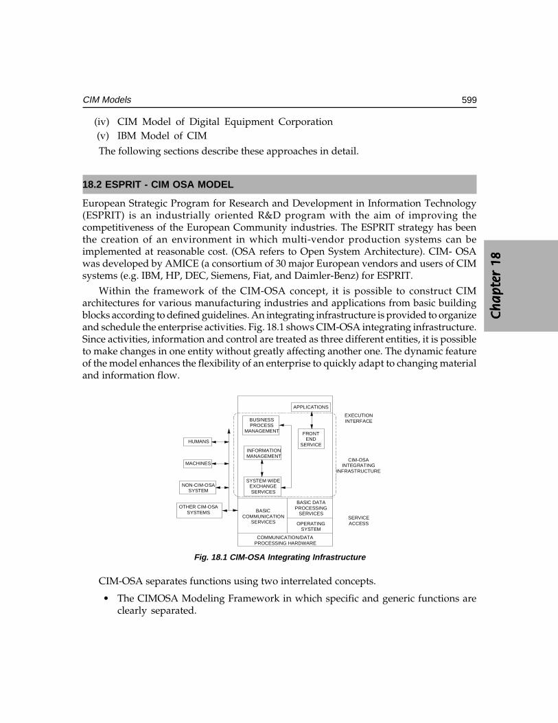
Ch
ap
ter
18C
ha
pte
r 18
Ch
ap
ter
18C
ha
pte
r 18
Ch
ap
ter
18
599CIM Models
(iv) CIM Model of Digital Equipment Corporation(v) IBM Model of CIM
The following sections describe these approaches in detail.
18.2 ESPRIT - CIM OSA MODEL
European Strategic Program for Research and Development in Information Technology(ESPRIT) is an industrially oriented R&D program with the aim of improving thecompetitiveness of the European Community industries. The ESPRIT strategy has beenthe creation of an environment in which multi-vendor production systems can beimplemented at reasonable cost. (OSA refers to Open System Architecture). CIM- OSAwas developed by AMICE (a consortium of 30 major European vendors and users of CIMsystems (e.g. IBM, HP, DEC, Siemens, Fiat, and Daimler-Benz) for ESPRIT.
Within the framework of the CIM-OSA concept, it is possible to construct CIMarchitectures for various manufacturing industries and applications from basic buildingblocks according to defined guidelines. An integrating infrastructure is provided to organizeand schedule the enterprise activities. Fig. 18.1 shows CIM-OSA integrating infrastructure.Since activities, information and control are treated as three different entities, it is possibleto make changes in one entity without greatly affecting another one. The dynamic featureof the model enhances the flexibility of an enterprise to quickly adapt to changing materialand information flow.
APPLICATIONS
BUSINESSPROCESS
MANAGEMENT FRONTEND
SERVICEINFORMATIONMANAGEMENT
SYSTEM WIDEEXCHANGESERVICES
BASICCOMMUNICATION
SERVICES
BASIC DATAPROCESSING
SERVICES
OPERATINGSYSTEM
EXECUTIONINTERFACE
CIM-OSAINTEGRATING
INFRASTRUCTURE
SERVICEACCESS
HUMANS
MACHINES
NON-CIM-OSASYSTEM
OTHER CIM-OSASYSTEMS
COMMUNICATION/DATAPROCESSING HARDWARE
Fig. 18.1 CIM-OSA Integrating Infrastructure
CIM-OSA separates functions using two interrelated concepts.
• The CIMOSA Modeling Framework in which specific and generic functions areclearly separated.
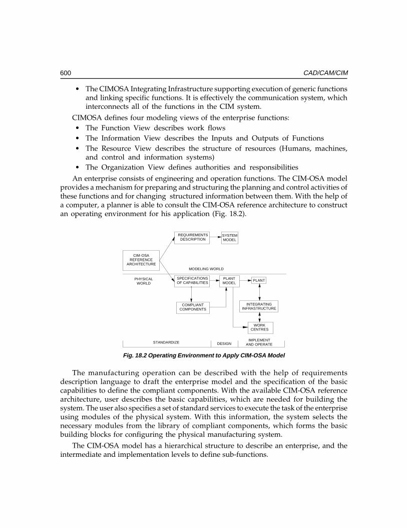
600 CAD/CAM/CIM
• The CIMOSA Integrating Infrastructure supporting execution of generic functionsand linking specific functions. It is effectively the communication system, whichinterconnects all of the functions in the CIM system.
CIMOSA defines four modeling views of the enterprise functions:• The Function View describes work flows• The Information View describes the Inputs and Outputs of Functions• The Resource View describes the structure of resources (Humans, machines,
and control and information systems)• The Organization View defines authorities and responsibilities
An enterprise consists of engineering and operation functions. The CIM-OSA modelprovides a mechanism for preparing and structuring the planning and control activities ofthese functions and for changing structured information between them. With the help ofa computer, a planner is able to consult the CIM-OSA reference architecture to constructan operating environment for his application (Fig. 18.2).
CIM-OSAREFERENCE
ARCHITECTURE
REQUIREMENTSDESCRIPTION
SPECIFICATIONSOF CAPABILITIES
SYSTEMMODEL
PLANTMODEL
PLANT
COMPLIANTCOMPONENTS
INTEGRATINGINFRASTRUCTURE
WORKCENTRES
STANDARDIZE DESIGNIMPLEMENT
AND OPERATE
MODELING WORLD
PHYSICALWORLD
Fig. 18.2 Operating Environment to Apply CIM-OSA Model
The manufacturing operation can be described with the help of requirementsdescription language to draft the enterprise model and the specification of the basiccapabilities to define the compliant components. With the available CIM-OSA referencearchitecture, user describes the basic capabilities, which are needed for building thesystem. The user also specifies a set of standard services to execute the task of the enterpriseusing modules of the physical system. With this information, the system selects thenecessary modules from the library of compliant components, which forms the basicbuilding blocks for configuring the physical manufacturing system.
The CIM-OSA model has a hierarchical structure to describe an enterprise, and theintermediate and implementation levels to define sub-functions.
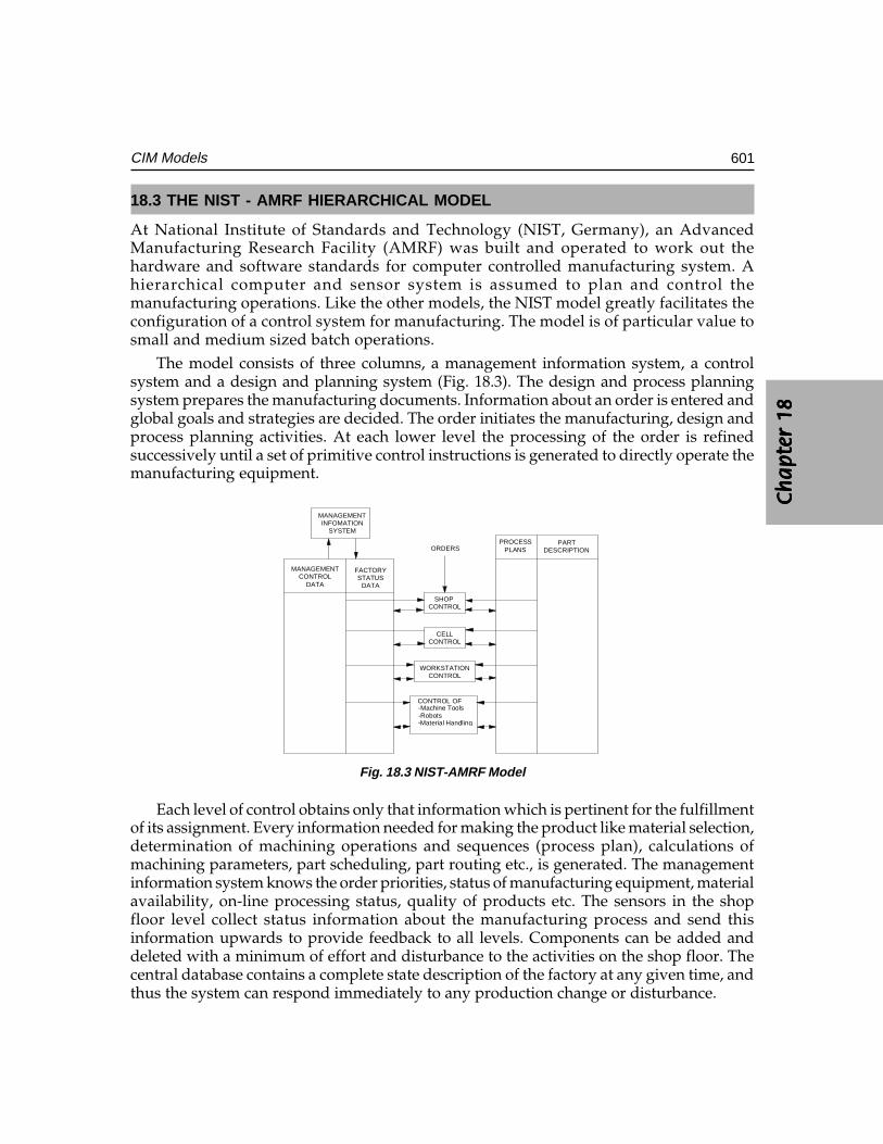
Ch
ap
ter
18C
ha
pte
r 18
Ch
ap
ter
18C
ha
pte
r 18
Ch
ap
ter
18
601CIM Models
18.3 THE NIST - AMRF HIERARCHICAL MODEL
At National Institute of Standards and Technology (NIST, Germany), an AdvancedManufacturing Research Facility (AMRF) was built and operated to work out thehardware and software standards for computer controlled manufacturing system. Ahierarchical computer and sensor system is assumed to plan and control themanufacturing operations. Like the other models, the NIST model greatly facilitates theconfiguration of a control system for manufacturing. The model is of particular value tosmall and medium sized batch operations.
The model consists of three columns, a management information system, a controlsystem and a design and planning system (Fig. 18.3). The design and process planningsystem prepares the manufacturing documents. Information about an order is entered andglobal goals and strategies are decided. The order initiates the manufacturing, design andprocess planning activities. At each lower level the processing of the order is refinedsuccessively until a set of primitive control instructions is generated to directly operate themanufacturing equipment.
MANAGEMENTINFOMATION
SYSTEM
PROCESSPLANS
PARTDESCRIPTION
MANAGEMENTCONTROL
DATA
FACTORYSTATUS
DATA
SHOP CONTROL
CELLCONTROL
WORKSTATIONCONTROL
CONTROL OF -Machine Tools
-Robots-Material Handling
ORDERS
Fig. 18.3 NIST-AMRF Model
Each level of control obtains only that information which is pertinent for the fulfillmentof its assignment. Every information needed for making the product like material selection,determination of machining operations and sequences (process plan), calculations ofmachining parameters, part scheduling, part routing etc., is generated. The managementinformation system knows the order priorities, status of manufacturing equipment, materialavailability, on-line processing status, quality of products etc. The sensors in the shopfloor level collect status information about the manufacturing process and send thisinformation upwards to provide feedback to all levels. Components can be added anddeleted with a minimum of effort and disturbance to the activities on the shop floor. Thecentral database contains a complete state description of the factory at any given time, andthus the system can respond immediately to any production change or disturbance.
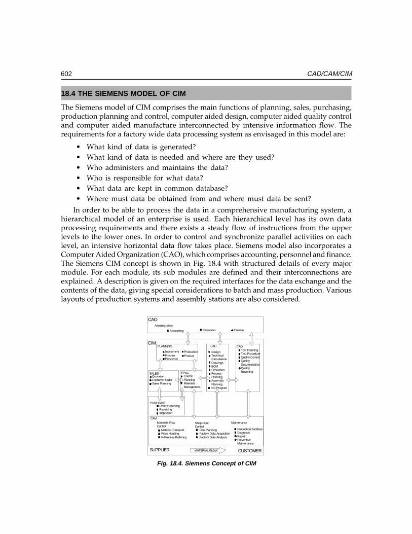
602 CAD/CAM/CIM
18.4 THE SIEMENS MODEL OF CIM
The Siemens model of CIM comprises the main functions of planning, sales, purchasing,production planning and control, computer aided design, computer aided quality controland computer aided manufacture interconnected by intensive information flow. Therequirements for a factory wide data processing system as envisaged in this model are:
• What kind of data is generated?• What kind of data is needed and where are they used?• Who administers and maintains the data?• Who is responsible for what data?• What data are kept in common database?• Where must data be obtained from and where must data be sent?
In order to be able to process the data in a comprehensive manufacturing system, ahierarchical model of an enterprise is used. Each hierarchical level has its own dataprocessing requirements and there exists a steady flow of instructions from the upperlevels to the lower ones. In order to control and synchronize parallel activities on eachlevel, an intensive horizontal data flow takes place. Siemens model also incorporates aComputer Aided Organization (CAO), which comprises accounting, personnel and finance.The Siemens CIM concept is shown in Fig. 18.4 with structured details of every majormodule. For each module, its sub modules are defined and their interconnections areexplained. A description is given on the required interfaces for the data exchange and thecontents of the data, giving special considerations to batch and mass production. Variouslayouts of production systems and assembly stations are also considered.
CAOAdministration
Accounting Personnel Finance
CIMPLANNING
InvestmentFinancePersonnel
ProductionProduct
CAD
DesignTechnicalCalculationsDrawingsBOMSimulationProcessPlanningAssemblyPlanningNC Program
CAQTest PlanningTest ProcedureQuality ControlQualityDocumentationQualityReporting
SALESQuotationCustomer OrderSales Planning
PP&CCoarsePlanningMaterialsManagement
PURCHASEOrder ReceivingReceivingInspection
CAMMaterials Flow Control
Shop FloorControl
Maintenance
Material TransportWare HousingIn Process Buffering
Fine PlanningFactory Data AcquisitionFactory Data Analysis
Production FacilitiesDiagnosisRepairPreventiveMaintenance
SUPPLIER MATERIAL FLOW CUSTOMER
Fig. 18.4. Siemens Concept of CIM
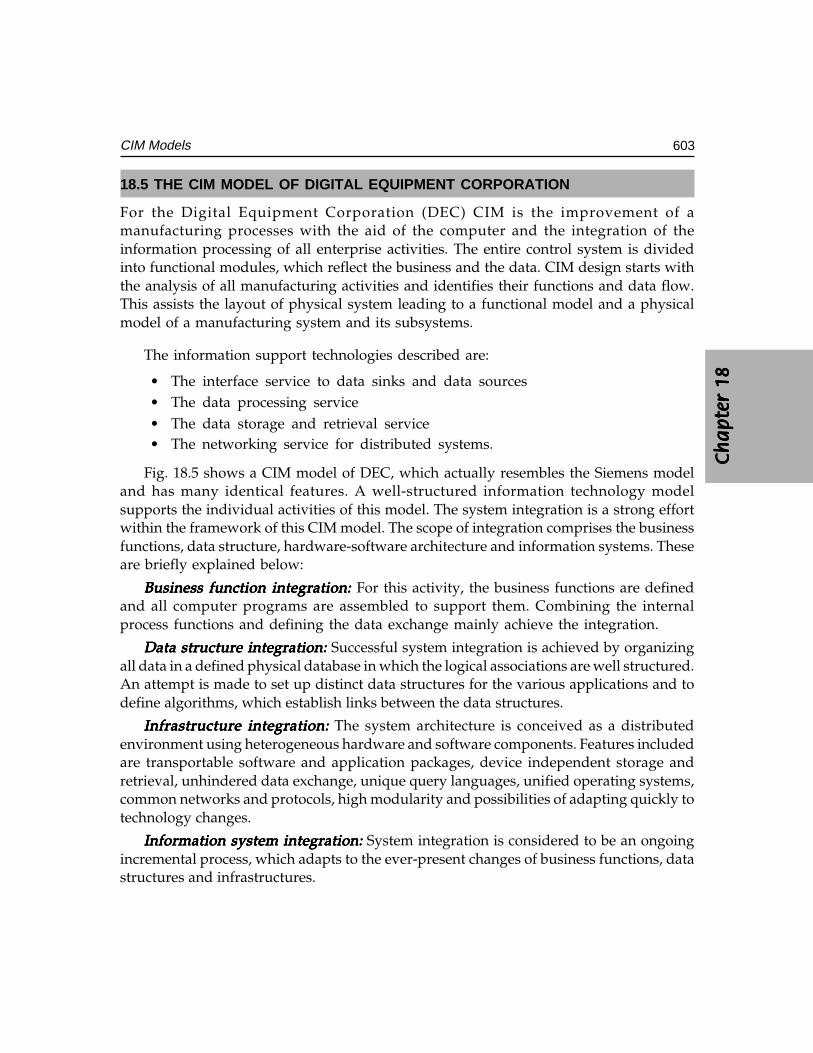
Ch
ap
ter
18C
ha
pte
r 18
Ch
ap
ter
18C
ha
pte
r 18
Ch
ap
ter
18
603CIM Models
18.5 THE CIM MODEL OF DIGITAL EQUIPMENT CORPORATION
For the Digital Equipment Corporation (DEC) CIM is the improvement of amanufacturing processes with the aid of the computer and the integration of theinformation processing of all enterprise activities. The entire control system is dividedinto functional modules, which reflect the business and the data. CIM design starts withthe analysis of all manufacturing activities and identifies their functions and data flow.This assists the layout of physical system leading to a functional model and a physicalmodel of a manufacturing system and its subsystems.
The information support technologies described are:
• The interface service to data sinks and data sources• The data processing service• The data storage and retrieval service• The networking service for distributed systems.
Fig. 18.5 shows a CIM model of DEC, which actually resembles the Siemens modeland has many identical features. A well-structured information technology modelsupports the individual activities of this model. The system integration is a strong effortwithin the framework of this CIM model. The scope of integration comprises the businessfunctions, data structure, hardware-software architecture and information systems. Theseare briefly explained below:
Business function integration:Business function integration:Business function integration:Business function integration:Business function integration: For this activity, the business functions are definedand all computer programs are assembled to support them. Combining the internalprocess functions and defining the data exchange mainly achieve the integration.
Data structure integration:Data structure integration:Data structure integration:Data structure integration:Data structure integration: Successful system integration is achieved by organizingall data in a defined physical database in which the logical associations are well structured.An attempt is made to set up distinct data structures for the various applications and todefine algorithms, which establish links between the data structures.
Infrastructure integration:Infrastructure integration:Infrastructure integration:Infrastructure integration:Infrastructure integration: The system architecture is conceived as a distributedenvironment using heterogeneous hardware and software components. Features includedare transportable software and application packages, device independent storage andretrieval, unhindered data exchange, unique query languages, unified operating systems,common networks and protocols, high modularity and possibilities of adapting quickly totechnology changes.
Information system integration:Information system integration:Information system integration:Information system integration:Information system integration: System integration is considered to be an ongoingincremental process, which adapts to the ever-present changes of business functions, datastructures and infrastructures.
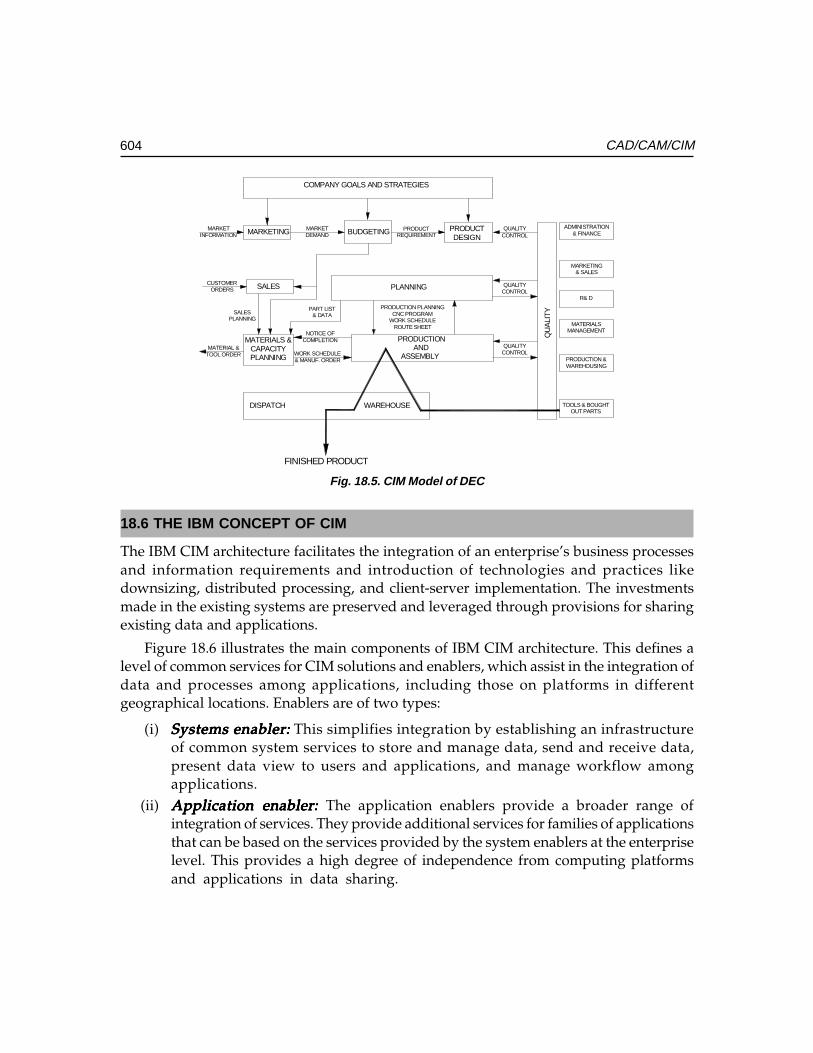
604 CAD/CAM/CIM
COMPANY GOALS AND STRATEGIES
MARKETING BUDGETING PRODUCTDESIGN
SALES
MATERIALS &CAPACITYPLANNING
PRODUCTIONAND
ASSEMBLY
PLANNING
MARKETINFORMATION
MARKETDEMAND
PRODUCTREQUIREMENT
DISPATCH WAREHOUSE
CUSTOMERORDERS
MATERIAL &TOOL ORDER
QU
ALI
TY
QUALITYCONTROL
QUALITYCONTROL
QUALITYCONTROL
ADMINISTRATION& FINANCE
MARKETING& SALES
R& D
MATERIALSMANAGEMENT
PRODUCTION &WAREHOUSING
TOOLS & BOUGHTOUT PARTS
NOTICE OFCOMPLETION
WORK SCHEDULE& MANUF. ORDER
PART LIST& DATA
PRODUCTION PLANNINGCNC PROGRAM
WORK SCHEDULEROUTE SHEET
SALESPLANNING
FINISHED PRODUCT
Fig. 18.5. CIM Model of DEC
18.6 THE IBM CONCEPT OF CIM
The IBM CIM architecture facilitates the integration of an enterprise’s business processesand information requirements and introduction of technologies and practices likedownsizing, distributed processing, and client-server implementation. The investmentsmade in the existing systems are preserved and leveraged through provisions for sharingexisting data and applications.
Figure 18.6 illustrates the main components of IBM CIM architecture. This defines alevel of common services for CIM solutions and enablers, which assist in the integration ofdata and processes among applications, including those on platforms in differentgeographical locations. Enablers are of two types:
(i) Systems enabler:Systems enabler:Systems enabler:Systems enabler:Systems enabler: This simplifies integration by establishing an infrastructureof common system services to store and manage data, send and receive data,present data view to users and applications, and manage workflow amongapplications.
(ii) Application enabler: Application enabler: Application enabler: Application enabler: Application enabler: The application enablers provide a broader range ofintegration of services. They provide additional services for families of applicationsthat can be based on the services provided by the system enablers at the enterpriselevel. This provides a high degree of independence from computing platformsand applications in data sharing.
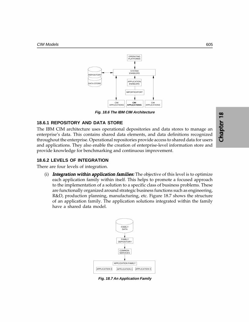
Ch
ap
ter
18C
ha
pte
r 18
Ch
ap
ter
18C
ha
pte
r 18
Ch
ap
ter
18
605CIM Models
OPERATINGPLATFORMS
SYSTEMENABLERS
APPLICATIONENABLERS
IMPORT/EXPORT
CIMAPPLICATIONS
CIMAPPLICATIONS
CIMAPPLICATIONS
CIMAPPLICATIONS
REPOSITORY
DATA STORE
Fig. 18.6 The IBM CIM Architecture
18.6.1 REPOSITORY AND DATA STOREThe IBM CIM architecture uses operational depositories and data stores to manage anenterprise’s data. This contains shared data elements, and data definitions recognizedthroughout the enterprise. Operational repositories provide access to shared data for usersand applications. They also enable the creation of enterprise-level information store andprovide knowledge for benchmarking and continuous improvement.
18.6.2 LEVELS OF INTEGRATIONThere are four levels of integration.
(i) Integration within application families:Integration within application families:Integration within application families:Integration within application families:Integration within application families: The objective of this level is to optimizeeach application family within itself. This helps to promote a focused approachto the implementation of a solution to a specific class of business problems. Theseare functionally organized around strategic business functions such as engineering,R&D, production planning, manufacturing, etc. Figure 18.7 shows the structureof an application family. The application solutions integrated within the familyhave a shared data model.
FAMILYDATA
FAMILYDEPOSITORY
COMMON SERVICES
APPLICATION FAMILY
APPLICATION 1 APPLICATION 3APPLICATION 3
Fig. 18.7 An Application Family
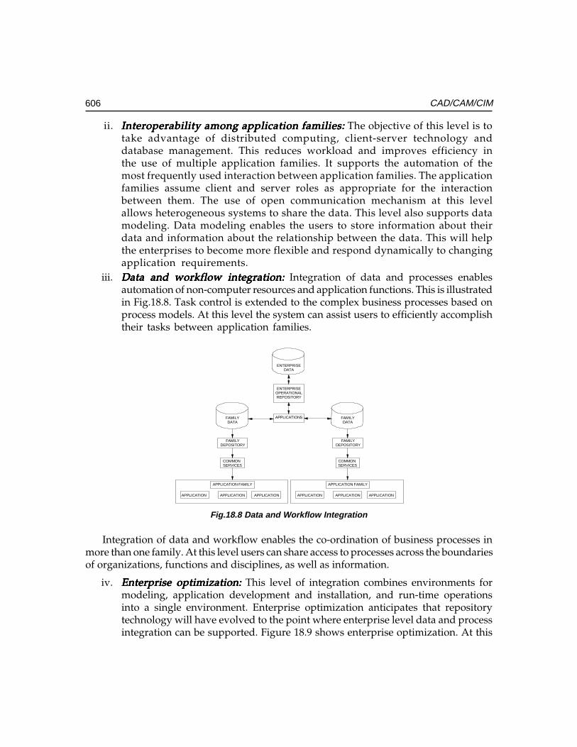
606 CAD/CAM/CIM
ii. Interoperability among application families:Interoperability among application families:Interoperability among application families:Interoperability among application families:Interoperability among application families: The objective of this level is totake advantage of distributed computing, client-server technology anddatabase management. This reduces workload and improves efficiency inthe use of multiple application families. It supports the automation of themost frequently used interaction between application families. The applicationfamilies assume client and server roles as appropriate for the interactionbetween them. The use of open communication mechanism at this levelallows heterogeneous systems to share the data. This level also supports datamodeling. Data modeling enables the users to store information about theirdata and information about the relationship between the data. This will helpthe enterprises to become more flexible and respond dynamically to changingapplication requirements.
iii. Data and workflow integration:Data and workflow integration:Data and workflow integration:Data and workflow integration:Data and workflow integration: Integration of data and processes enablesautomation of non-computer resources and application functions. This is illustratedin Fig.18.8. Task control is extended to the complex business processes based onprocess models. At this level the system can assist users to efficiently accomplishtheir tasks between application families.
ENTERPRISEOPERATIONALREPOSITORY
APPLICATIONS FAMILYDATA
FAMILYDEPOSITORY
COMMON SERVICES
APPLICATION FAMILY
FAMILYDATA
FAMILYDEPOSITORY
COMMON SERVICES
APPLICATION FAMILY
APPLICATION APPLICATION APPLICATION APPLICATION APPLICATION APPLICATION
ENTERPRISEDATA
Fig.18.8 Data and Workflow Integration
Integration of data and workflow enables the co-ordination of business processes inmore than one family. At this level users can share access to processes across the boundariesof organizations, functions and disciplines, as well as information.
iv. Enterprise optimization:Enterprise optimization:Enterprise optimization:Enterprise optimization:Enterprise optimization: This level of integration combines environments formodeling, application development and installation, and run-time operationsinto a single environment. Enterprise optimization anticipates that repositorytechnology will have evolved to the point where enterprise level data and processintegration can be supported. Figure 18.9 shows enterprise optimization. At this
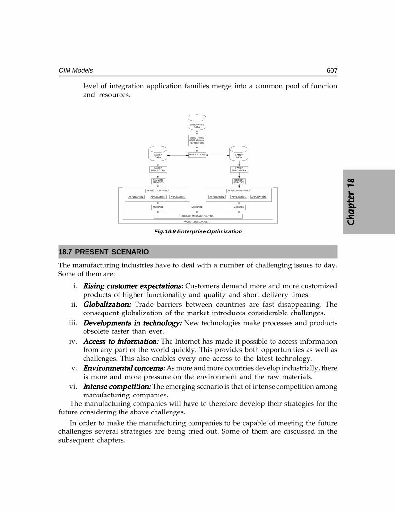
Ch
ap
ter
18C
ha
pte
r 18
Ch
ap
ter
18C
ha
pte
r 18
Ch
ap
ter
18
607CIM Models
level of integration application families merge into a common pool of functionand resources.
ENTERPRISEOPERATIONALREPOSITORY
APPLICATIONS FAMILYDATA
FAMILYDEPOSITORY
COMMON SERVICES
APPLICATION FAMILY
FAMILYDATA
FAMILYDEPOSITORY
COMMON SERVICES
APPLICATION FAMILY
APPLICATION APPLICATION APPLICATION APPLICATION APPLICATION APPLICATION
ENTERPRISEDATA
MESSAGEMESSAGE MESSAGE
COMMON MESSAGE ROUTING
WORK FLOW MANAGER
Fig.18.9 Enterprise Optimization
18.7 PRESENT SCENARIO
The manufacturing industries have to deal with a number of challenging issues to day.Some of them are:
i. Rising customer expectations:Rising customer expectations:Rising customer expectations:Rising customer expectations:Rising customer expectations: Customers demand more and more customizedproducts of higher functionality and quality and short delivery times.
ii. Globalization:Globalization:Globalization:Globalization:Globalization: Trade barriers between countries are fast disappearing. Theconsequent globalization of the market introduces considerable challenges.
iii. Developments in technology:Developments in technology:Developments in technology:Developments in technology:Developments in technology: New technologies make processes and productsobsolete faster than ever.
iv. Access to information:Access to information:Access to information:Access to information:Access to information: The Internet has made it possible to access informationfrom any part of the world quickly. This provides both opportunities as well aschallenges. This also enables every one access to the latest technology.
v. Environmental concerns:Environmental concerns:Environmental concerns:Environmental concerns:Environmental concerns: As more and more countries develop industrially, thereis more and more pressure on the environment and the raw materials.
vi. Intense competition:Intense competition:Intense competition:Intense competition:Intense competition: The emerging scenario is that of intense competition amongmanufacturing companies.
The manufacturing companies will have to therefore develop their strategies for thefuture considering the above challenges.
In order to make the manufacturing companies to be capable of meeting the futurechallenges several strategies are being tried out. Some of them are discussed in thesubsequent chapters.

608 CAD/CAM/CIM
QUESTIONS
1. Discuss the changes in product development approaches and their influencein shaping manufacturing strategies.
2. Compare different CIM Models with particular reference to the flow of information.3. Analyze the manufacturing operations of a company and prepare a report as to
how the IBM CIM model could be implemented in the company.
����������
������ ��
�������
������
A Flexible Manufacturing System (FMS) is an integrated approach to automating a productionsystem with a view to accommodate fast response to product changes. The primary natureof an FMS is that it is a computer-controlled manufacturing system that ties together storage,manufacturing machines, inspection, tooling and materials handling equipment. The FMSis designed to be flexible so that it can manufacture a variety of products at relatively lowvolumes, with minimum lead time between product changes.
19.1 INTRODUCTION
Intense competition in the global market for mechanical parts manufactured on machinetools and other metal working equipment has compelled manufacturers to reduce deliverytimes and quote competitive prices even for relatively small orders. In many situations,manufacturers have to deliver customized products to the consumers. The batch size isever-decreasing, and the need to meet specific customer needs calls for considerableflexibility in the working of the manufacturing system.
In this situation, the requirements that a modern manufacturing facility has to meetcan be detailed as follows:
• High productivity for all batch sizes, large or small• Shorter throughput times• Lower storage costs• Reduced labour if not altogether avoiding labour• Reduced handling• Flexible production system to incorporate product changes at short notice to meet
customer’s specific requirements• Sensing and taking care of such eventualities like tool breakage.
Conventional high volume production facilities such as automatic equipment andtransfer lines do not fulfill these requirements. This provided sufficient reason for
610 CAD/CAM/CIM
manufacturing engineers to turn attention to alternative approaches to manufacturing.Flexible manufacturing cells and flexible manufacturing systems have been evolved tomeet the requirements listed above.
The functions of many manufacturing equipment have already been automatedthrough the use of CNC and PLC. The next stage is to automate the wider manufacturingenvironment comprising the following activities:
• Management of resources• Storage, preparation and transport of raw workpieces and finished components• Acquisition, processing and evaluation of production data• Inspection of workpieces and continuously monitoring the performance of
production equipment• Testing of products• Developing software to control all the above operations.
In such a process of integrated automation it is necessary to combine a number ofmachines, both mechanically and in terms of data processing into a closely linkedmanufacturing unit. In this way, highly automated manufacturing units (cells) are createdwhich are capable of handling a number of different workpieces without interruptionsdue to operations like setting up workpieces, tool change, inspection etc.
Monitoring and process correction facilities through appropriate sensors are also partof the system so that operator intervention is kept to a bare minimum.
Manufacturing cells normally contain 1 to 4 production machines. In addition to various“service machines” such as measuring machines and washing machines) and transportsystems like automated guided vehicles, rail guided vehicles and conveyors for theworkpieces and for the tools.
The cell computer simultaneously controls the manufacturing operations within themanufacturing cell.
19.2 SUBSYSTEMS OF FMS
There are three major subsystems in FMS:
(i) Computer-controlled manufacturing equipment (e.g. numerically controlledmachine tools, robots, gantry loaders, palletizing systems, washing stations, toolpre-setters, in-process inspection systems etc.)
(ii) Automated materials storage, retrieval, transport and transfer system(iii) Manufacturing control system (including both machine tool, tool and logistics
control)Some FMS’s have additional subsystems. For example, in a machining application there
may also be systems for presetting tools, storing and retrieving tools, disposing of chipsand cutting fluids, washing and inspection workpieces. These subsystems must be linkedtogether to achieve integrated manufacturing operation.
Ch
ap
ter
19C
ha
pte
r 19
Ch
ap
ter
19C
ha
pte
r 19
Ch
ap
ter
19
611Flexible Manufacturing Systems
19.3 SCOPE OF FMS
Although this was initially developed for machining applications, the concept of FMShas subsequently been used in a variety of other manufacturing applications, such as:
• Assembly of equipments• Semiconductor component manufacturing• Plastic injection moulding••••• Sheet metal fabrication• Welding• Textile machinery manufacture
Such systems have proved to be practical and economical for applications with thefollowing characteristics:
• Families of parts with similar geometric features that require similar types ofequipment and processes
• A moderate number of tools and process steps• Low to medium quantities of parts• Moderate precision requirements
19.4 FMS COMPARED TO OTHER TYPES OF MANUFACTURING APPROACHES
One-off and low volumes of production are normally carried out by conventional generalpurpose machine tools. When the number of parts in a production run is more it is calledbatch production. A batch production shop is best suited for small quantities of manydifferent types of parts. The very nature of production makes the operation of a job shopless efficient than an automated production line.
Since the job shop must be provided the greatest degree of flexibility, most of itsoperations are manual. They are normally equipped with general purpose CNC machinetools. Hard automation with dedicated equipment is best suited for the production of verylarge quantities of identical parts. Production of automobile components in a transfer linefalls under this category. A large portion of the manufacturing industry involves theintermediate level of batch operations that lend themselves to the FMS approach. In thiscase volume is less but varieties are more.
FMS thus basically attempts to efficiently automate batch manufacturing operations.They are an alternative that fits in between the manual job shop and hard automation.FMS is best suited for applications that involve an intermediate level of flexibility and lowor medium quantities. Fig. 19.1 shows the different types of production systems and itcan be seen from the figure that FMS fits into the intermediate range of production.General purpose machines can accommodate a large variety of parts. They are manually
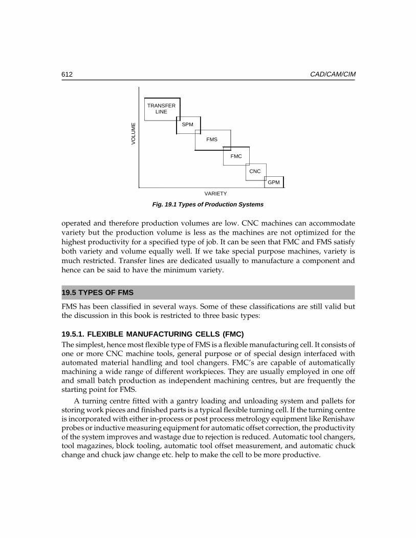
612 CAD/CAM/CIM
operated and therefore production volumes are low. CNC machines can accommodatevariety but the production volume is less as the machines are not optimized for thehighest productivity for a specified type of job. It can be seen that FMC and FMS satisfyboth variety and volume equally well. If we take special purpose machines, variety ismuch restricted. Transfer lines are dedicated usually to manufacture a component andhence can be said to have the minimum variety.
19.5 TYPES OF FMS
FMS has been classified in several ways. Some of these classifications are still valid butthe discussion in this book is restricted to three basic types:
19.5.1. FLEXIBLE MANUFACTURING CELLS (FMC)The simplest, hence most flexible type of FMS is a flexible manufacturing cell. It consists ofone or more CNC machine tools, general purpose or of special design interfaced withautomated material handling and tool changers. FMC’s are capable of automaticallymachining a wide range of different workpieces. They are usually employed in one offand small batch production as independent machining centres, but are frequently thestarting point for FMS.
A turning centre fitted with a gantry loading and unloading system and pallets forstoring work pieces and finished parts is a typical flexible turning cell. If the turning centreis incorporated with either in-process or post process metrology equipment like Renishawprobes or inductive measuring equipment for automatic offset correction, the productivityof the system improves and wastage due to rejection is reduced. Automatic tool changers,tool magazines, block tooling, automatic tool offset measurement, and automatic chuckchange and chuck jaw change etc. help to make the cell to be more productive.
TRANSFERLINE
SPM
FMS
FMC
CNC
GPM
VARIETY
VO
LUM
E
Fig. 19.1 Types of Production Systems
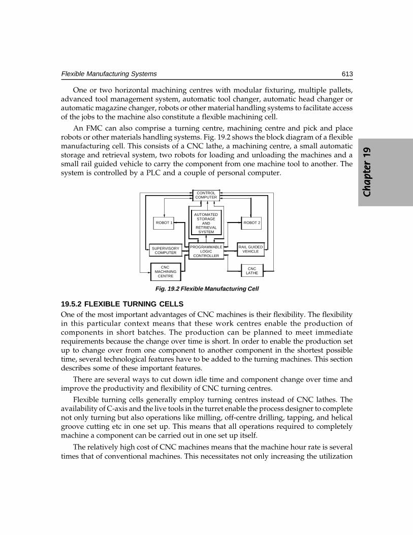
Ch
ap
ter
19C
ha
pte
r 19
Ch
ap
ter
19C
ha
pte
r 19
Ch
ap
ter
19
613Flexible Manufacturing Systems
One or two horizontal machining centres with modular fixturing, multiple pallets,advanced tool management system, automatic tool changer, automatic head changer orautomatic magazine changer, robots or other material handling systems to facilitate accessof the jobs to the machine also constitute a flexible machining cell.
An FMC can also comprise a turning centre, machining centre and pick and placerobots or other materials handling systems. Fig. 19.2 shows the block diagram of a flexiblemanufacturing cell. This consists of a CNC lathe, a machining centre, a small automaticstorage and retrieval system, two robots for loading and unloading the machines and asmall rail guided vehicle to carry the component from one machine tool to another. Thesystem is controlled by a PLC and a couple of personal computer.
ROBOT 1
SUPERVISORYCOMPUTER
CNC MACHINING
CENTRE
AUTOMATEDSTORAGE
ANDRETRIEVAL
SYSTEM
PROGRAMMABLELOGIC
CONTROLLER
RAIL GUIDEDVEHICLE
ROBOT 2
CONTROLCOMPUTER
CNCLATHE
Fig. 19.2 Flexible Manufacturing Cell
19.5.2 FLEXIBLE TURNING CELLSOne of the most important advantages of CNC machines is their flexibility. The flexibilityin this particular context means that these work centres enable the production ofcomponents in short batches. The production can be planned to meet immediaterequirements because the change over time is short. In order to enable the production setup to change over from one component to another component in the shortest possibletime, several technological features have to be added to the turning machines. This sectiondescribes some of these important features.
There are several ways to cut down idle time and component change over time andimprove the productivity and flexibility of CNC turning centres.
Flexible turning cells generally employ turning centres instead of CNC lathes. Theavailability of C-axis and the live tools in the turret enable the process designer to completenot only turning but also operations like milling, off-centre drilling, tapping, and helicalgroove cutting etc in one set up. This means that all operations required to completelymachine a component can be carried out in one set up itself.
The relatively high cost of CNC machines means that the machine hour rate is severaltimes that of conventional machines. This necessitates not only increasing the utilization
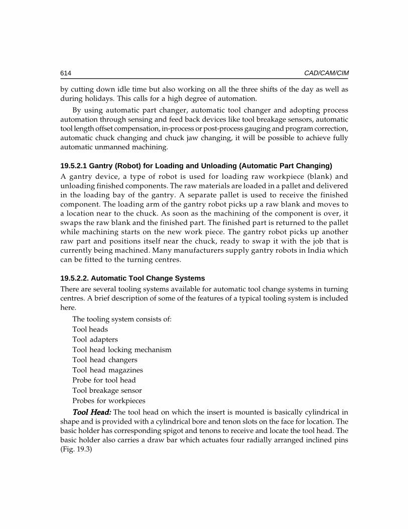
614 CAD/CAM/CIM
by cutting down idle time but also working on all the three shifts of the day as well asduring holidays. This calls for a high degree of automation.
By using automatic part changer, automatic tool changer and adopting processautomation through sensing and feed back devices like tool breakage sensors, automatictool length offset compensation, in-process or post-process gauging and program correction,automatic chuck changing and chuck jaw changing, it will be possible to achieve fullyautomatic unmanned machining.
19.5.2.1 Gantry (Robot) for Loading and Unloading (Automatic Part Changing)A gantry device, a type of robot is used for loading raw workpiece (blank) andunloading finished components. The raw materials are loaded in a pallet and deliveredin the loading bay of the gantry. A separate pallet is used to receive the finishedcomponent. The loading arm of the gantry robot picks up a raw blank and moves toa location near to the chuck. As soon as the machining of the component is over, itswaps the raw blank and the finished part. The finished part is returned to the palletwhile machining starts on the new work piece. The gantry robot picks up anotherraw part and positions itself near the chuck, ready to swap it with the job that iscurrently being machined. Many manufacturers supply gantry robots in India whichcan be fitted to the turning centres.
19.5.2.2. Automatic Tool Change SystemsThere are several tooling systems available for automatic tool change systems in turningcentres. A brief description of some of the features of a typical tooling system is includedhere.
The tooling system consists of:Tool headsTool adaptersTool head locking mechanismTool head changersTool head magazinesProbe for tool headTool breakage sensorProbes for workpieces
Tool Head:Tool Head:Tool Head:Tool Head:Tool Head: The tool head on which the insert is mounted is basically cylindrical inshape and is provided with a cylindrical bore and tenon slots on the face for location. Thebasic holder has corresponding spigot and tenons to receive and locate the tool head. Thebasic holder also carries a draw bar which actuates four radially arranged inclined pins(Fig. 19.3)
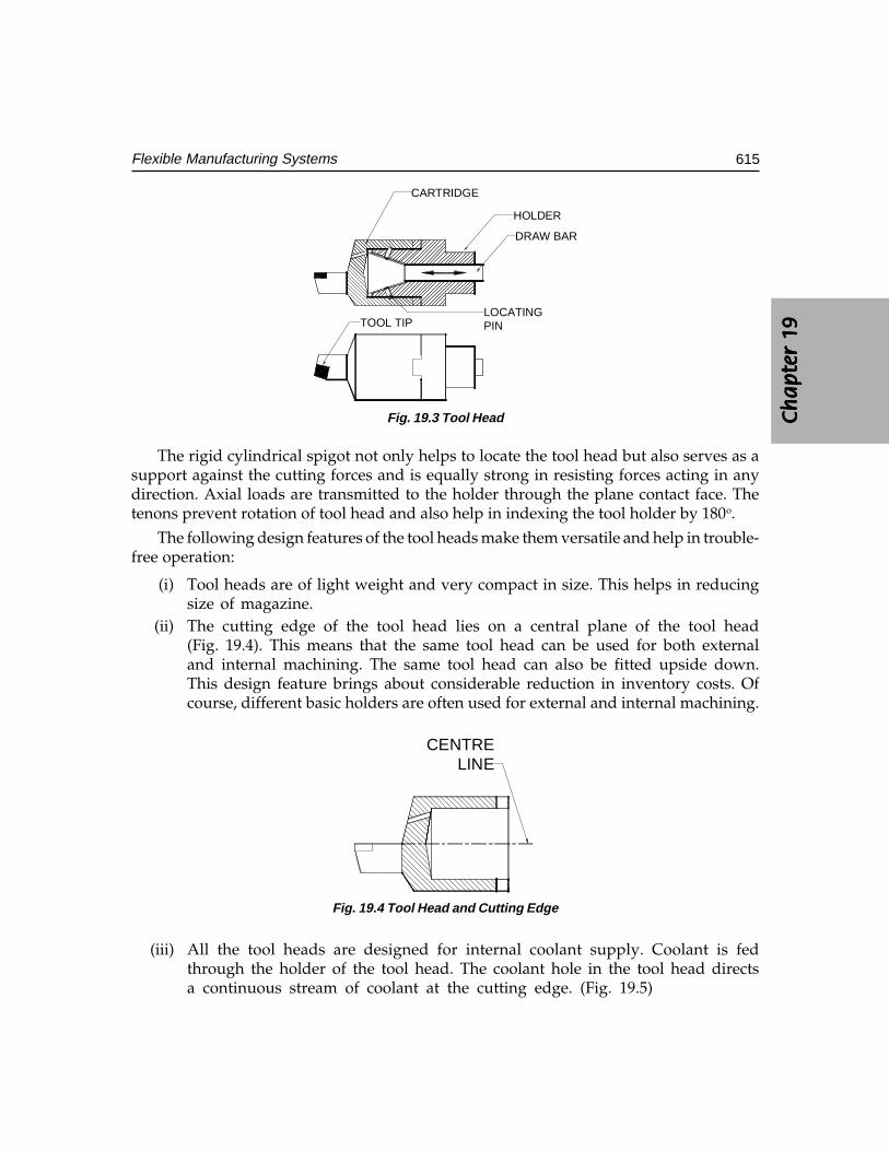
Ch
ap
ter
19C
ha
pte
r 19
Ch
ap
ter
19C
ha
pte
r 19
Ch
ap
ter
19
615Flexible Manufacturing Systems
DRAW BAR
HOLDER
CARTRIDGE
LOCATINGPINTOOL TIP
Fig. 19.3 Tool Head
The rigid cylindrical spigot not only helps to locate the tool head but also serves as asupport against the cutting forces and is equally strong in resisting forces acting in anydirection. Axial loads are transmitted to the holder through the plane contact face. Thetenons prevent rotation of tool head and also help in indexing the tool holder by 180o.
The following design features of the tool heads make them versatile and help in trouble-free operation:
(i) Tool heads are of light weight and very compact in size. This helps in reducingsize of magazine.
(ii) The cutting edge of the tool head lies on a central plane of the tool head(Fig. 19.4). This means that the same tool head can be used for both externaland internal machining. The same tool head can also be fitted upside down.This design feature brings about considerable reduction in inventory costs. Ofcourse, different basic holders are often used for external and internal machining.
CENTRELINE
Fig. 19.4 Tool Head and Cutting Edge
(iii) All the tool heads are designed for internal coolant supply. Coolant is fedthrough the holder of the tool head. The coolant hole in the tool head directsa continuous stream of coolant at the cutting edge. (Fig. 19.5)
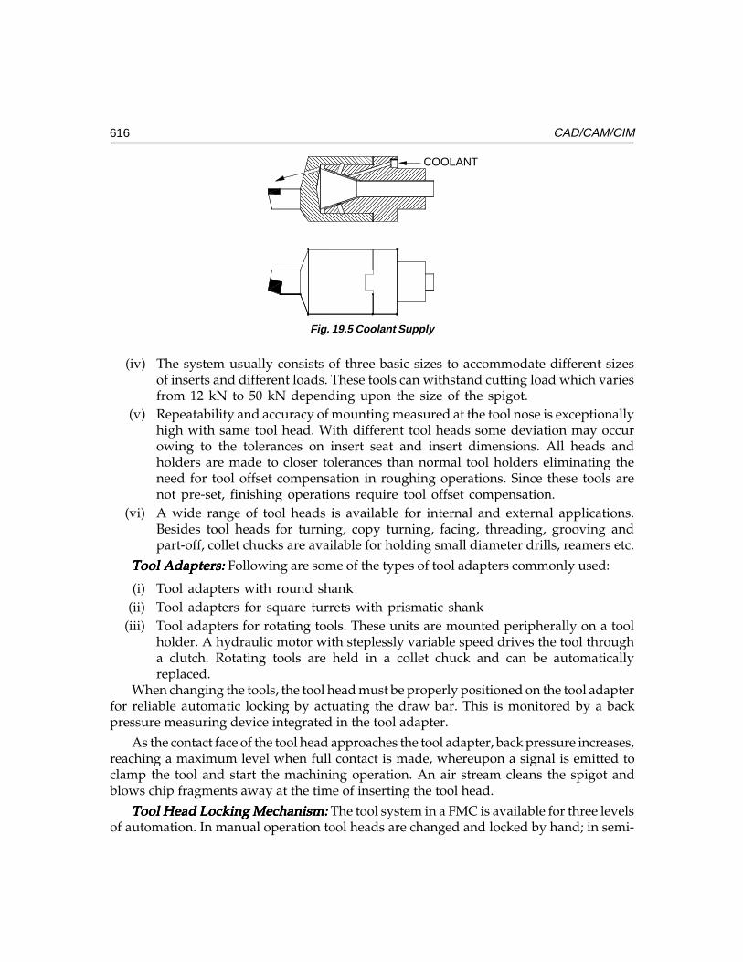
616 CAD/CAM/CIM
COOLANT
Fig. 19.5 Coolant Supply
(iv) The system usually consists of three basic sizes to accommodate different sizesof inserts and different loads. These tools can withstand cutting load which variesfrom 12 kN to 50 kN depending upon the size of the spigot.
(v) Repeatability and accuracy of mounting measured at the tool nose is exceptionallyhigh with same tool head. With different tool heads some deviation may occurowing to the tolerances on insert seat and insert dimensions. All heads andholders are made to closer tolerances than normal tool holders eliminating theneed for tool offset compensation in roughing operations. Since these tools arenot pre-set, finishing operations require tool offset compensation.
(vi) A wide range of tool heads is available for internal and external applications.Besides tool heads for turning, copy turning, facing, threading, grooving andpart-off, collet chucks are available for holding small diameter drills, reamers etc.
Tool Adapters:Tool Adapters:Tool Adapters:Tool Adapters:Tool Adapters: Following are some of the types of tool adapters commonly used:
(i) Tool adapters with round shank(ii) Tool adapters for square turrets with prismatic shank
(iii) Tool adapters for rotating tools. These units are mounted peripherally on a toolholder. A hydraulic motor with steplessly variable speed drives the tool througha clutch. Rotating tools are held in a collet chuck and can be automaticallyreplaced.
When changing the tools, the tool head must be properly positioned on the tool adapterfor reliable automatic locking by actuating the draw bar. This is monitored by a backpressure measuring device integrated in the tool adapter.
As the contact face of the tool head approaches the tool adapter, back pressure increases,reaching a maximum level when full contact is made, whereupon a signal is emitted toclamp the tool and start the machining operation. An air stream cleans the spigot andblows chip fragments away at the time of inserting the tool head.
Tool Head Locking Mechanism: Tool Head Locking Mechanism: Tool Head Locking Mechanism: Tool Head Locking Mechanism: Tool Head Locking Mechanism: The tool system in a FMC is available for three levelsof automation. In manual operation tool heads are changed and locked by hand; in semi-
Ch
ap
ter
19C
ha
pte
r 19
Ch
ap
ter
19C
ha
pte
r 19
Ch
ap
ter
19
617Flexible Manufacturing Systems
automatic operation tools are changed by hand but locked and released by a motor ; infully automatic operation locking/releasing, tool changing and process monitoring areautomatic, necessitating the use of appropriate magazine, tool changer, tool locking andprocess monitoring equipment.
Tool Head Magazines:Tool Head Magazines:Tool Head Magazines:Tool Head Magazines:Tool Head Magazines: Tool magazines accommodate all the tools required in themachine for a given workpiece or a group of workpieces. Magazine capacity ranges from24 to 120 tools. Generally, 30 to 60 tool stations are sufficient for one shift. As discussedearlier, tools are held in the magazine by short spigots. Simple mechanical features locatethe tool and prevent it from rotating or falling off. This concept offers the advantage thatused tools can be deposited in vacant stations.
Various designs of tool magazines are available, e.g. drum, rail or disc types. In setupswhere the magazine is not driven, the tool changer will execute all movements.
Tool Head Changer:Tool Head Changer:Tool Head Changer:Tool Head Changer:Tool Head Changer: Tool head handling can be effected, for instance, by a hydraulictool changer attached to the lathe’s longitudinal slide by an intermediate member.Depending on the workpiece and the machining operation, various standard designs areemployed.
The simplest set-up is for shaft work only, where all tools are for external machiningand mounted on radial tool holders. The tool changer then consists of one rotational andtwo translational hydraulic units.
Chucking work generally requires the use of radially mounted external tools as well asaxially mounted internal tools. Owing to the additional 900 turn required the tool changercomprises two rotational and three translational units. Any industrial robot meeting theserequirements can be used as a tool changer. The cylindrical spigot on the tool holder featuresan entering groove which permits trouble-free coupling of tool head and tool holder.
Probe for Tool Head:Probe for Tool Head:Probe for Tool Head:Probe for Tool Head:Probe for Tool Head: Besides tools, magazines and grippers, the tooling system alsoincludes all the sensors required in automatic operation for measuring and monitoring theprocess. An interface circuit transduces the signals received from a sensor into controlpulses for the CNC system. In addition to reliability, integrated microelectronics also offersshort response times, an advantage for quicker tool breakage detection.
Any tool in the lathe can be checked for offset along the X and Z axes. The tool to bechecked is taken to the probe, like a Renishaw LP-2 signal emitting type sensor. The signalemitted is processed at the interface circuit and passed on to the CNC system which thencompares the actual value with a preset value and automatically compensates for anyvariation in tool offset. Pre-setting of tools and fixtures is therefore rendered superfluous.
Tool Monitoring:Tool Monitoring:Tool Monitoring:Tool Monitoring:Tool Monitoring: Completely automated machining calls for continuous monitoringof tool to sense end of tool life due to gradual wear, breakage of tool due to chipping orcollision in order to avoid further damage. Tool monitoring systems help in sensing aboveevents and in avoiding damage to tool and reducing down time of machine.
A tool monitoring system consists of three individual components for sensing collision,breakage and wear.
618 CAD/CAM/CIM
All these systems work according to simple and reliable principle of measurement.During machining, cutting forces are continuously sensed through a strain transducermounted on the machine. Any variation during the process of machining leads to a changein the cutting force which is sensed by the strain transducer. If the previously set value iscrossed, then the device gives within a few milliseconds an impulse for the feed to stop.
The system consists essentially of the strain transducer, signal conditioning andprocessing electronics and the machine interface. The piezo-electric strain transducer ismounted on that part of the machine which is subject to maximum deformation. This isusually the turret housing. The signals picked up during machining operation are evaluatedcontinuously by the microprocessors in the system.
Collision Monitor:Collision Monitor:Collision Monitor:Collision Monitor:Collision Monitor: Automatic collision monitoring starts with the establishment of athreshold value of forces. The machine tool is first run through the machining programmefor the specific workpiece. The transducer measures the forces that are set up and gives adigital read-out of the maximum value. At the press of a button, this value plus a safetyallowance is transferred to the decode switch and acts as a force threshold for the monitoringprocess. When the programme is run again the collision control system automaticallymonitors the machine for collision. If process data exceeds the preset threshold, a signal isemitted to shut down the feed motor within 3 milliseconds. At the same time the operatoris alerted by visual and audible warning signals.
The turning centre programme cannot be resumed until the fault signal has beenacknowledged, either manually via a push-button or by the control system via the clear(CLR) signal. If cutting parameters are changed substantially, a new cut-out threshold hasto be established. Under certain conditions the system can even detect tool breakage, forexample if the force setup by breakage exceeds the preset threshold.
Continuous Wear:Continuous Wear:Continuous Wear:Continuous Wear:Continuous Wear: The turning centre operation can be made much more cost-effectiveby the wear control system. By determining when a tool is worn, the risk of scrap productionas a result of blunt tools is eliminated. This also reduces the risk of cutting edge breakage.The monitoring strategy for wear control is based on the measurement of the rise in forceover tool life. This rise is dependent on a number of parameters which cannot be definedin advance. They have to be learnt by the system in a teach-in phase covering the usefullife of a standard reference cutting edge. Instead of the teach-in-phase the operator canalso key in a rise-in-force value or call up from memory a previously established value.
During machining, the wear monitoring unit continuously calculates the extent of wearof each tool in use and displays the value. The operator knows at a glance how much timeremains until the next tool change. The system thus permits timely tool setting and helpseffective production scheduling.
After a workpiece has been machined the relevant tool is checked for wear. A wearmessage appears on the display giving the relevant tool number. As soon as this messageis acknowledged a new message is displayed instructing the operator to change the tool.Only when tool replacement has been effected and confirmed can production be resumed.
Ch
ap
ter
19C
ha
pte
r 19
Ch
ap
ter
19C
ha
pte
r 19
Ch
ap
ter
19
619Flexible Manufacturing Systems
Breakage Monitor: Breakage Monitor: Breakage Monitor: Breakage Monitor: Breakage Monitor: Breakage monitor is a system offering versatility in tool monitoring.It provides automatic detection and programmable response to breakage, collision, spallingand tool vibrations.
To ensure complete reliability in performing all control functions the tool breakagemonitoring and control system employs three monitoring strategies. The first involves asafety limit. The high force signal caused by collision exceeds this limit and the feed motoris shut down immediately. Collision is thus detected effectively and automatically.
The second strategy involves the system’s microprocessor monitoring every cut andcomparing it with a predetermined force value. If this value is exceeded the feed monitoris stopped instantaneously.
In a third strategy the system looks out for specific events which are typical of toolbreakage. When a tool breaks sudden high-frequency peaks occur in the components ofthe cutting force in radial and feed directions. These peaks, which do not occur in normaloperation, are due to particles of the shattered tool becoming jammed between workpieceand cutting edge. As they break free the cutting forces drop briefly to zero. The breakagemonitoring system, working with preset upper and lower tolerance limits, respondsimmediately when either of these limits is transgressed and within 2 milliseconds emits asignal to stop the feed. By means of a special stop module the feed drive is shut downwithin 20 milliseconds.
Probe for Workpiece Gauging:Probe for Workpiece Gauging:Probe for Workpiece Gauging:Probe for Workpiece Gauging:Probe for Workpiece Gauging: The workpiece gauging probe permits in-processworkpiece gauging with integrated tool offset compensation via the CNC system. Bothinside and outside diameters can be measured as well as lengths. Gauging is done by aRenishaw LP2-3D probe with a replaceable stylus. The probe is mounted in a speciallydesigned head and placed on an external or internal tool holder as required. Duringmachining the probe is stored in the magazine for protection. The signal is transferred tothe interface either by cable or via contactless induction coils or through infrared emission.The probe is calibrated with the aid of a reference plane in the machine.
19.5.3. FLEXIBLE TRANSFER LINES (FTL)Flexible transfer lines are intended for high volume production. A part in a high volumeproduction may have to undergo large number of operations. Each operation is assignedto and performed on only one machine. This results in a fixed route for each part throughthe system. The material handling system is usually a pallet or carousel or conveyor. Inaddition to general purpose machines, it can consist of SPM’s, robots and some dedicatedequipment. Scheduling to balance the machine loads is easier. Unlike conventional transferlines, a number of different workpieces can be manufactured on the FTL. The resettingprocedure is largely automatic.
19.5.4. FLEXIBLE MACHINING SYSTEMSFlexible Machining Systems consists of several flexible automated machine tools of theuniversal or special type which are flexibly interlinked by an automatic workpiece flow
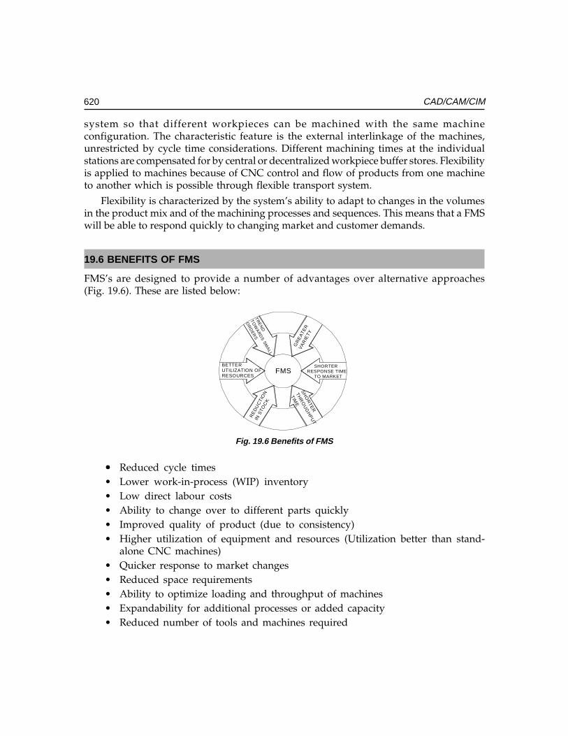
620 CAD/CAM/CIM
system so that different workpieces can be machined with the same machineconfiguration. The characteristic feature is the external interlinkage of the machines,unrestricted by cycle time considerations. Different machining times at the individualstations are compensated for by central or decentralized workpiece buffer stores. Flexibilityis applied to machines because of CNC control and flow of products from one machineto another which is possible through flexible transport system.
Flexibility is characterized by the system’s ability to adapt to changes in the volumesin the product mix and of the machining processes and sequences. This means that a FMSwill be able to respond quickly to changing market and customer demands.
19.6 BENEFITS OF FMS
FMS’s are designed to provide a number of advantages over alternative approaches(Fig. 19.6). These are listed below:
FMS
RE
DU
CTI
ON
IN S
TOC
KS
HO
RTE
R
THR
OU
GH
PU
T
TIME
SHORTER RESPONSE TIME
TO MARKET
BETTERUTILIZATION OFRESOURCES
GR
EA
TER
VA
RIE
TYT
RE
ND
TO
WA
RD
S S
MA
LL
OR
DE
RS
Fig. 19.6 Benefits of FMS
••••• Reduced cycle times• Lower work-in-process (WIP) inventory• Low direct labour costs• Ability to change over to different parts quickly• Improved quality of product (due to consistency)• Higher utilization of equipment and resources (Utilization better than stand-
alone CNC machines)• Quicker response to market changes• Reduced space requirements• Ability to optimize loading and throughput of machines• Expandability for additional processes or added capacity• Reduced number of tools and machines required
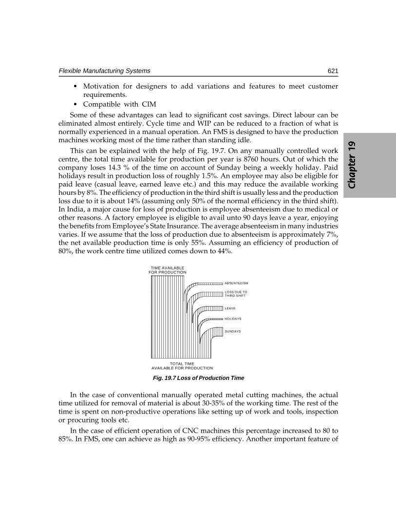
Ch
ap
ter
19C
ha
pte
r 19
Ch
ap
ter
19C
ha
pte
r 19
Ch
ap
ter
19
621Flexible Manufacturing Systems
• Motivation for designers to add variations and features to meet customerrequirements.
• Compatible with CIMSome of these advantages can lead to significant cost savings. Direct labour can be
eliminated almost entirely. Cycle time and WIP can be reduced to a fraction of what isnormally experienced in a manual operation. An FMS is designed to have the productionmachines working most of the time rather than standing idle.
This can be explained with the help of Fig. 19.7. On any manually controlled workcentre, the total time available for production per year is 8760 hours. Out of which thecompany loses 14.3 % of the time on account of Sunday being a weekly holiday. Paidholidays result in production loss of roughly 1.5%. An employee may also be eligible forpaid leave (casual leave, earned leave etc.) and this may reduce the available workinghours by 8%. The efficiency of production in the third shift is usually less and the productionloss due to it is about 14% (assuming only 50% of the normal efficiency in the third shift).In India, a major cause for loss of production is employee absenteeism due to medical orother reasons. A factory employee is eligible to avail unto 90 days leave a year, enjoyingthe benefits from Employee’s State Insurance. The average absenteeism in many industriesvaries. If we assume that the loss of production due to absenteeism is approximately 7%,the net available production time is only 55%. Assuming an efficiency of production of80%, the work centre time utilized comes down to 44%.
SUNDAYS
HOLIDAYS
LEAVE
LOSS DUE TOTHIRD SHIFT
ABSENTEEISM
TIME AVAILABLEFOR PRODUCTION
TOTAL TIMEAVAILABLE FOR PRODUCTION
Fig. 19.7 Loss of Production Time
In the case of conventional manually operated metal cutting machines, the actualtime utilized for removal of material is about 30-35% of the working time. The rest of thetime is spent on non-productive operations like setting up of work and tools, inspectionor procuring tools etc.
In the case of efficient operation of CNC machines this percentage increased to 80 to85%. In FMS, one can achieve as high as 90-95% efficiency. Another important feature of
622 CAD/CAM/CIM
FMS is that an FMS can produce parts even if the employee is absent or even if it is aholiday. The significance of FMS must be apparent from this fact.
An automated material handling system and a computer-based productionscheduling system are needed to keep the machines fed with parts. FMS uses computerautomation techniques to lower the overall cost of production operations.
19.7 MAJOR ELEMENTS OF FMS
Each of the major subsystems in an FMS performs a number of functions and is dependenton the others to make the entire system work. The functions will vary, depending uponthe type of equipment and manufacturing operations involved.
19.7.1 PRODUCTION EQUIPMENTThe production equipment used in FMS depends upon the product manufactured.
(i) FMS for sheet metal work:FMS for sheet metal work:FMS for sheet metal work:FMS for sheet metal work:FMS for sheet metal work: The work centres used in sheet metal FMS includeturret punch presses, laser machining centres, press brakes, guillotines etc. Atypical FMC consists of sheet stacking system, sheet unloading device, sortingconveyor, turret punch press, right angle shear, loading device and automaticstorage.
(ii) FMS for machining: FMS for machining: FMS for machining: FMS for machining: FMS for machining: This type of FMS typically has a number of machining centresand/or turning centres to provide general purpose machining capabilities. Machiningcenters offer the greatest flexibility, since they can perform many different machiningoperations. (e.g. milling, drilling, and boring). This is made possible by a tool-changing system that is either built into or supports the machining centre. A partcan therefore undergo multiple machining processes at a single workstation. Specialpurpose machines may also be included in the FMS to perform operations whichare unique or require more efficiency (e.g. turning, grinding). Washing machinesand inspection machines also form the equipment of FMS.
The family of parts which the FMS is designed to produce will determine the capabilitiesrequired from the machine tools (e.g. accuracy, size, power etc). Details of the CNC machinetools are given in Chapter 12.
19.7.2 SUPPORT SYSTEMSAutomated machine tools typically require several systems to support their operation.The tools required to perform the multiple processes of a machining centre or a turningcentre may be stored in magazines at each machine or in central tool storage. Localmagazines provide fast access as well as backup capability but in a large FMS a centraltool facility may be more efficient. Centralization not only permits the total number oftools to be minimized; it also provides the opportunity to perform additional functionsautomatically, such as:
Ch
ap
ter
19C
ha
pte
r 19
Ch
ap
ter
19C
ha
pte
r 19
Ch
ap
ter
19
623Flexible Manufacturing Systems
(i) Measurement of tool wear(ii) Tool pre-setting
(iii) Tool regrinding, repair and maintenance(iv) Replacement of broken or worn tools
Many automated machine tools have built-in systems to monitor tool wear anddetect tool breakage. They may use probes or non-contact techniques such as acousticemission for this purpose. When a tool needs replacement, the machine can signal thetool room for the delivery of a replacement. This may be performed by an AGV organtry set up or RGV.
Elaborate tool management support is an integral part of FMS software. With thissoftware, operating personnel can have effective centralized control of a large tool inventory.
Automated machining operations also need to have the chips cleaned off the workstationand the workpiece. This may be performed by robots or special washing stations. Cleaningmay involve turning the workpiece over, vacuuming and washing.
19.7.3 MATERIALS HANDLING SYSTEM
••••• A FMS typically needs several materials handling systems to service the machines.••••• A transport system to move workpieces into and out of the FMS (e.g. overhead
conveyors, gantry systems, AGV’s, RGV’s)••••• A buffer storage system for queues of workpieces at the machines (e.g., pallets)••••• A transfer system to load and unload the machines (e.g. robots, transfer fixtures)
For these systems to work effectively, they must be synchronized with the machineoperations. The location and movement of workpieces must be tracked automatically. Thisis done by using sensors on the materials handling system and workstations.
They may be either contact devices (e.g. switches) or non-contact devices (e.g. optical,RFID tags or proximity devices).
19.7.3.1 Automatic Guided Vehicles (AGV)AGV is one of the widely used types of material handling device in an FMS. These arebattery-powered vehicles that can move and transfer materials by following prescribedpaths around the shop floor. They are neither physically tied to the production line nordriven by an operator like forklift. Such vehicles have on-board controllers that can beprogrammed for complicated and varying routes as well as load and unload operations.The computer for the materials handling system or the central computer provides overallcontrol functions, such as dispatching, routing and traffic control and collision avoidance.AGV’s usually complement an automated production line consisting of conveyor or transfersystems by providing the flexibility of complex and programmable movement around themanufacturing shop.
624 CAD/CAM/CIM
Advantages of using AGV systems in FMSAdvantages of using AGV systems in FMSAdvantages of using AGV systems in FMSAdvantages of using AGV systems in FMSAdvantages of using AGV systems in FMS
(i)(i)(i)(i)(i) Flexibility:Flexibility:Flexibility:Flexibility:Flexibility: The route of the AGV’s can be easily altered, expanded and modified,simply by changing the guide path of the vehicles. This is more cost effective thanmodifying fixed conveyor lines or rail guided vehicles. It provides direct accessmaterials handling system for loading and unloading FMS cells and accessing theautomated storage and retrieval system.
(ii)(ii)(ii)(ii)(ii) Real time monitoring and control:Real time monitoring and control:Real time monitoring and control:Real time monitoring and control:Real time monitoring and control: Because of computer control, AGV’s can bemonitored in real time. If the FMS control system decides to change the schedule,the vehicles can be re-routed and urgent requests can be served. AGV’s areusually controlled through wires implanted on the factory floor. The control iseffected using a variable frequency approach.
Radio control, an alternative to in-floor mounted communication lines, permits twoway communications between the on-board computer and a remote computer, independentof where the vehicle is i.e. whether it is in the parking place or whether it is in motion. Toissue a command to a vehicle, the central computer sends a bit stream via its transmitterusing frequency shift keying methods to address a specific vehicle. The signal transmittedfrom the base station is, therefore, read by the appropriate vehicle only. The vehicle is alsocapable of sending signals back to the remote controller, to report the status of the vehicle,vehicle malfunction, battery status, and so on.
(iii)(iii)(iii)(iii)(iii) Safety: Safety: Safety: Safety: Safety: AGV’s can travel at a slow speed but typically operate in the range 10to 70 m/min. They have on-board microprocessor control to communicate withlocal zone controllers which direct the traffic and prevent collisions betweenvehicles as well as the vehicle and other objects. A bumper is attached to somedesigns of AGV’s to prevent collision.
AGV’s may also incorporate warning lights, fire safety interlocks and controls for safetyin shops. During design, the use of simulation can help detect whether there are enoughvehicles to perform the necessary load, unload and transportation tasks and thus optimizethe utilization of the AGV system. Because these vehicles have to work in a tandem withhighly organized FMS cells as well as with automated warehouses under computer control,their level of performance will affect the entire efficiency of the FMS.
19.7.4 AUTOMATED STORAGE AND RETRIEVAL SYSTEMSA key part of any materials handling system is storage. Major advances have been made inrecent years to automate the storage and retrieval of product and materials by employingsophisticated materials handling machines, high-density storage techniques and computercontrol. Such systems come in a variety of forms and sizes depending on the materialshandling and storage job that has to be done. They often take the form of automatedwarehouses which use automatic storage and retrieval systems, conveyors and computersto control the materials handling machines and to track and control the inventory. Thecharacteristics of such warehouses include:
Ch
ap
ter
19C
ha
pte
r 19
Ch
ap
ter
19C
ha
pte
r 19
Ch
ap
ter
19
625Flexible Manufacturing Systems
(i) High density storage (in some cases, large, high-rise rack structures)(ii) Automated handling systems (such as elevators, storage and retrieval carousels
and conveyors).(iii) Materials tracking systems (using optical or magnetic sensors)
In such a storage system, the computer can keep track of a large number of differentparts, products and materials and can assign bin locations to optimize the use of storagespace. When such a system is tied into the production control system, parts and materialscan be replenished as they are consumed on the factory floor, keeping the work in process(WIP) to a minimum.
19.7.4.1. Categories of AS/RSThe automatic storage and retrieval system can be classified into several types. Some ofthem are:
• Unit load AS/RS• Mini load AS/RS• Man-on-board AS/RS• Automated item retrieval system• Deep lane AS/RS
19.7.4.2 Basic Components of AS/RSAn AS/RS normally consists of:
• Storage structure• Storage and retrieval machine• Storage modules• Pick-up and deposit stations
19.7.4.3 Special Features of AS/RSSome of the special features of AS/RS are:
• Aisle transfer cars• Full/empty bin detectors• Sizing stations• Load identification stations
19.7.5 BUFFER STORING OF PARTSIn an FMS, parts move from one work cell to another where the various processing tasksare performed. Because of the almost random production facilities of FMS, the destinationcell might not always ready to accept the incoming part and the part has to wait in a bufferstore. These and other bottlenecks in the materials handling problems can be successfully
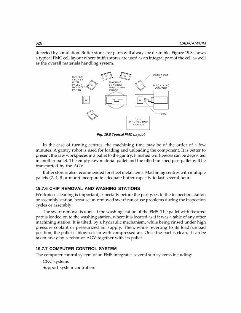
626 CAD/CAM/CIM
detected by simulation. Buffer stores for parts will always be desirable. Figure 19.8 showsa typical FMC cell layout where buffer stores are used as an integral part of the cell as wellas the overall materials handling system.
BU FFERSTOR ESW IT HPALLETM O U N TEDPAR TS
M AC HIN ELOAD IN G/U NLO ADIN GR O BO T
M ACHININGCE NTRE
C E LLIN P U T/OU TP U T
S TATIO N
W O R K PIE C EWWW
W
W
W
W
TO OL
Fig. 19.8 Typical FMC Layout
In the case of turning centres, the machining time may be of the order of a fewminutes. A gantry robot is used for loading and unloading the component. It is better topresent the raw workpieces in a pallet to the gantry. Finished workpieces can be depositedin another pallet. The empty raw material pallet and the filled finished part pallet will betransported by the AGV.
Buffer store is also recommended for sheet metal items. Machining centres with multiplepallets (2, 4, 8 or more) incorporate adequate buffer capacity to last several hours.
19.7.6 CHIP REMOVAL AND WASHING STATIONSWorkpiece cleaning is important, especially before the part goes to the inspection stationor assembly station, because un-removed swarf can cause problems during the inspectioncycles or assembly.
The swarf removal is done at the washing station of the FMS. The pallet with fixturedpart is loaded on to the washing station, where it is located as if it was a table of any othermachining station. It is tilted, by a hydraulic mechanism, while being rinsed under highpressure coolant or pressurized air supply. Then, while reverting to its load/unloadposition, the pallet is blown clean with compressed air. Once the part is clean, it can betaken away by a robot or AGV together with its pallet.
19.7.7 COMPUTER CONTROL SYSTEMThe computer control system of an FMS integrates several sub-systems including:
CNC systemsSupport system controllers
Ch
ap
ter
19C
ha
pte
r 19
Ch
ap
ter
19C
ha
pte
r 19
Ch
ap
ter
19
627Flexible Manufacturing Systems
Materials handling system controllerMonitoring and sensing devicesData communication systemData collection systemProgrammable logic controllersSupervisory computerThis control system must also integrate other computer systems if existing in the
factory. The FMS system must also communicate with the following systems:
• The CAD/CAM system which generates the CNC programs for the machinetools
• The shop floor control systems which schedules loading and routing of the work• The management information system (MIS) system which provides management
with reports on the performance of the systemThe various controllers and computers can be arranged in the form of a LAN for this
purpose.The type of the supervisory computer depends upon the size of FMS. A powerful
server will be adequate as a control computer.
19.8 OPTIMISATION OF FMS
An FMS requires considerable investment. Thorough planning and analysis should precedethe purchase of a FMS as the FMS should be designed to provide efficient operation.
Following are some approaches which should be considered in order to optimize theoverall efficiency and effectiveness of FMS:
i. Minimizing the process cycle time:Minimizing the process cycle time:Minimizing the process cycle time:Minimizing the process cycle time:Minimizing the process cycle time: The process must be designed to minimizemachining and handling.
ii. Maximizing the utilization of each machine:Maximizing the utilization of each machine:Maximizing the utilization of each machine:Maximizing the utilization of each machine:Maximizing the utilization of each machine: This can be done by balancing thework load in the system and real time scheduling.
iii. Use of automated storage systems to keep work ready for machines to process:Use of automated storage systems to keep work ready for machines to process:Use of automated storage systems to keep work ready for machines to process:Use of automated storage systems to keep work ready for machines to process:Use of automated storage systems to keep work ready for machines to process:The raw work parts must be replenished as and when needed to avoid starvingthe work centres.
iv. Provision of adequate sensors for the detection of errors or problems: Provision of adequate sensors for the detection of errors or problems: Provision of adequate sensors for the detection of errors or problems: Provision of adequate sensors for the detection of errors or problems: Provision of adequate sensors for the detection of errors or problems: Thisincludes the detection of the presence and absence of parts, jamming, tool wear,machine failures, and so on. This can be done with the use of vision systems,limit switches, proximity switches etc. In some cases special sensors like toolmonitoring systems are used.
v. Backup capabilities:Backup capabilities:Backup capabilities:Backup capabilities:Backup capabilities: Redundancy is important in ensuring trouble-free operationof the FMS. The system should be able to run even when failures occur (e.g., usespare tools, provision to isolate defective machines, supply of alternative materials
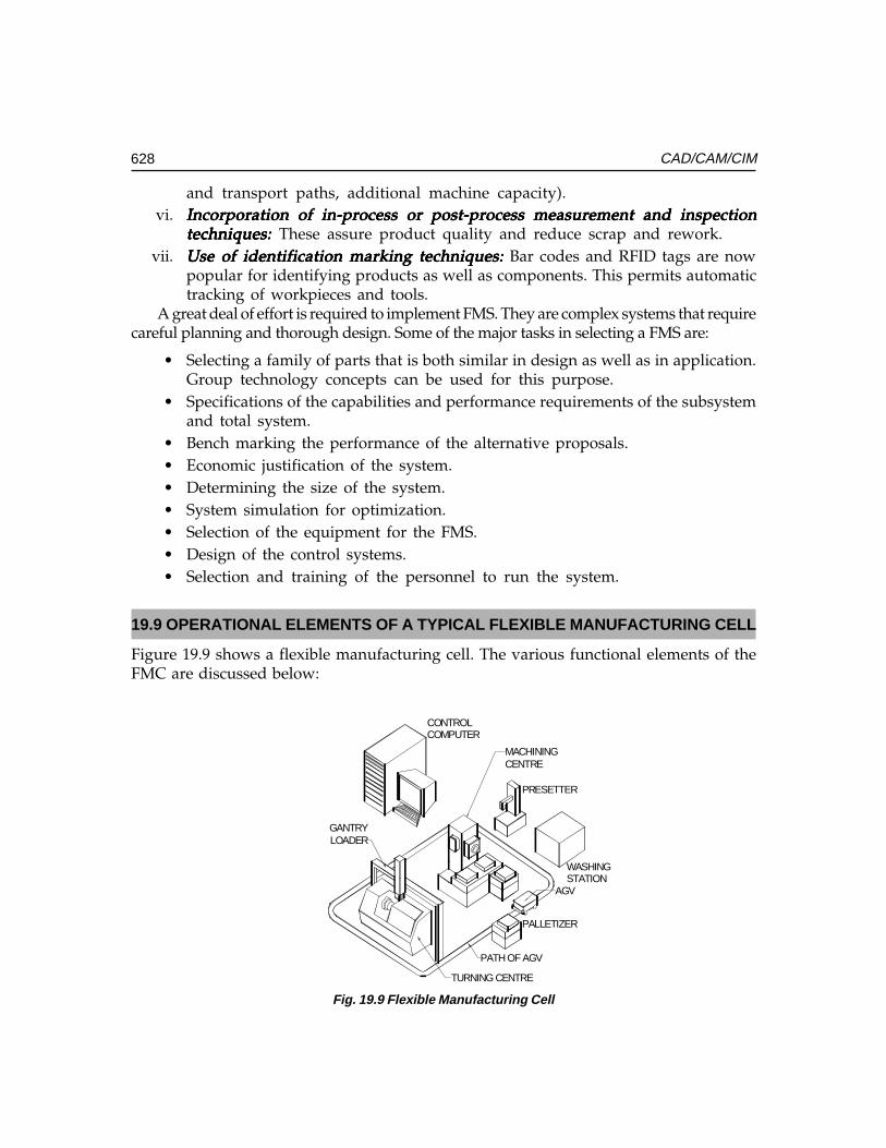
628 CAD/CAM/CIM
and transport paths, additional machine capacity).vi. Incorporation of in-process or post-process measurement and inspectionIncorporation of in-process or post-process measurement and inspectionIncorporation of in-process or post-process measurement and inspectionIncorporation of in-process or post-process measurement and inspectionIncorporation of in-process or post-process measurement and inspection
techniques:techniques:techniques:techniques:techniques: These assure product quality and reduce scrap and rework.vii. Use of identification marking techniques:Use of identification marking techniques:Use of identification marking techniques:Use of identification marking techniques:Use of identification marking techniques: Bar codes and RFID tags are now
popular for identifying products as well as components. This permits automatictracking of workpieces and tools.
A great deal of effort is required to implement FMS. They are complex systems that requirecareful planning and thorough design. Some of the major tasks in selecting a FMS are:
• Selecting a family of parts that is both similar in design as well as in application.Group technology concepts can be used for this purpose.
• Specifications of the capabilities and performance requirements of the subsystemand total system.
• Bench marking the performance of the alternative proposals.• Economic justification of the system.• Determining the size of the system.• System simulation for optimization.• Selection of the equipment for the FMS.• Design of the control systems.• Selection and training of the personnel to run the system.
19.9 OPERATIONAL ELEMENTS OF A TYPICAL FLEXIBLE MANUFACTURING CELL
Figure 19.9 shows a flexible manufacturing cell. The various functional elements of theFMC are discussed below:
WASHINGSTATION
PRESETTER
PALLETIZER
TURNING CENTRE
AGV
PATH OF AGV
GANTRYLOADER
MACHININGCENTRE
CONTROLCOMPUTER
Fig. 19.9 Flexible Manufacturing Cell
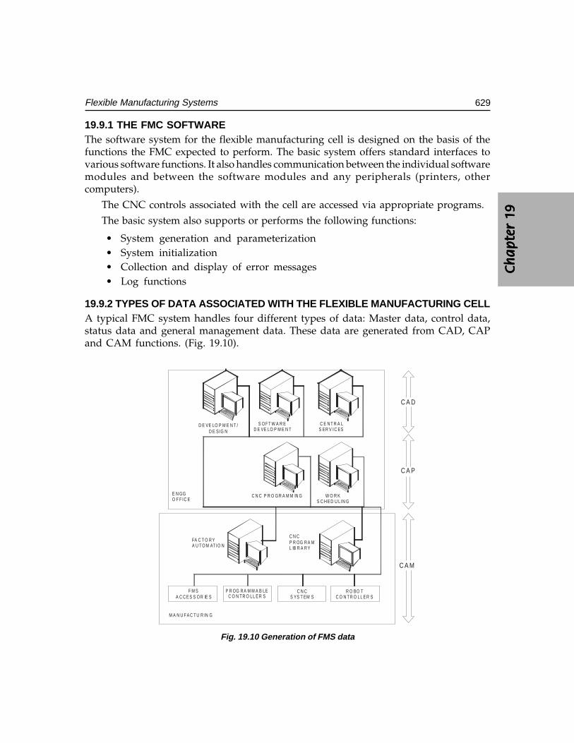
Ch
ap
ter
19C
ha
pte
r 19
Ch
ap
ter
19C
ha
pte
r 19
Ch
ap
ter
19
629Flexible Manufacturing Systems
19.9.1 THE FMC SOFTWAREThe software system for the flexible manufacturing cell is designed on the basis of thefunctions the FMC expected to perform. The basic system offers standard interfaces tovarious software functions. It also handles communication between the individual softwaremodules and between the software modules and any peripherals (printers, othercomputers).
The CNC controls associated with the cell are accessed via appropriate programs.
The basic system also supports or performs the following functions:
• System generation and parameterization• System initialization• Collection and display of error messages• Log functions
19.9.2 TYPES OF DATA ASSOCIATED WITH THE FLEXIBLE MANUFACTURING CELLA typical FMC system handles four different types of data: Master data, control data,status data and general management data. These data are generated from CAD, CAPand CAM functions. (Fig. 19.10).
F M SA C C E S S O R IE S
P R OG R A M M A B LEC O N T R O L L E R S
C N CS YS T EM S
R O BO TC O N T R O L L E R S
D E VE LO P M E N T /D E SIG N
S O F T W A R ED E VE LO P M E N T
C E N T R A LS ER V IC ES
C N C P R O G R A M M IN G W O R KS C H E D U LIN G
FA C T O R YA U T O M AT IO N
C N CP R OG R A ML IB R A R Y
E N GGO F F IC E
M A N U F A C T U R IN G
C A D
C A P
C A M
Fig. 19.10 Generation of FMS data
630 CAD/CAM/CIM
These are discussed below:
(i) Master data:Master data:Master data:Master data:Master data: Master data have to be set up only once when the flexiblemanufacturing cell is put into operation and this comprise:System-specific data (related to the architecture of the system) and
Resource master data which include:
(a) Tool master data(b) Workpiece carrier master data (data relating to the workpiece carriers and
clamping fixtures)
(ii) Control data:Control data:Control data:Control data:Control data: Control data are product-specific data.(a) CNC programs, tool layouts and work schedules (technical control data)(b) manufacturing orders (organizational control data)
(iii) Status data:Status data:Status data:Status data:Status data: Status data describes the current situation with regard to resources:(a) Plant status data(b) Resources data(c) Work piece carrier data(d) Tool data(e) Work piece data
(iv) Log data:Log data:Log data:Log data:Log data: All operational data and machine data required for later analysis anddiagnostics are recorded, evaluated by the software function modules and filledwith details of data and time of day. Such data include the following:(a) Machine specific messages
(e.g. from CNC, PLC, handling devices, transport system)
• Status and operational messages(e.g. NC start, NC end, NC program run time)
• Alarms(e.g. machine fault)
(b) Tool specific messages(e.g. tool break, end of tool life)
(c) NC messages(e.g. load NC program)
(d) Entry and description of fault by way of a dialogue
There are system statuses in which the data are not in a defined stated, namely:
• Initial start (all data), and• Restart after complete or partial loss of data
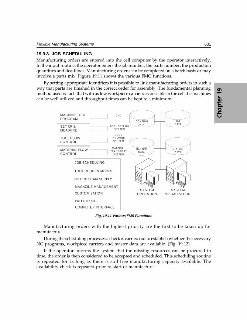
Ch
ap
ter
19C
ha
pte
r 19
Ch
ap
ter
19C
ha
pte
r 19
Ch
ap
ter
19
631Flexible Manufacturing Systems
19.9.3. JOB SCHEDULINGManufacturing orders are entered into the cell computer by the operator interactively.In the input routine, the operator enters the job number, the parts number, the productionquantities and deadlines. Manufacturing orders can be completed on a batch basis or mayinvolve a parts mix. Figure 19.11 shows the various FMC functions.
By setting appropriate identifiers it is possible to link manufacturing orders in such away that parts are finished in the correct order for assembly. The fundamental planningmethod used is such that with as few workpiece carriers as possible in the cell the machinescan be well utilized and throughput times can be kept to a minimum.
SYSTEMOPERATION
SYSTEMVISUALIZATION
JOB SCHEDULING
TOOL REQUIREMENTS
NC PROGRAM SUPPLY
MAGAZINE MANAGEMENT
CUSTOMIZATION
PALLETIZING
COMPUTER INTERFACE
MACHINE TOOLPROGRAM
SET UP &MEASURE
TOOL FLOW CONTROL
MATERIAL FLOWCONTROL
C ON T R O LD ATA
LO GD ATA
M A S TE R D ATA
S TATU SD ATA
C NC
T OO L S E TT IN GS Y S TE M
T OO LTA N S P O RT
S Y S TE M
M AT E R IA LT R A NS P O R T
S Y S TE M
Fig. 19.11 Various FMS Functions
Manufacturing orders with the highest priority are the first to be taken up formanufacture.
During the scheduling processes a check is carried out to establish whether the necessaryNC programs, workpiece carriers and master data are available. (Fig. 19.12).
If the operator informs the system that the missing resources can be procured intime, the order is then considered to be accepted and scheduled. This scheduling routineis repeated for as long as there is still free manufacturing capacity available. Theavailability check is repeated prior to start of manufacture.
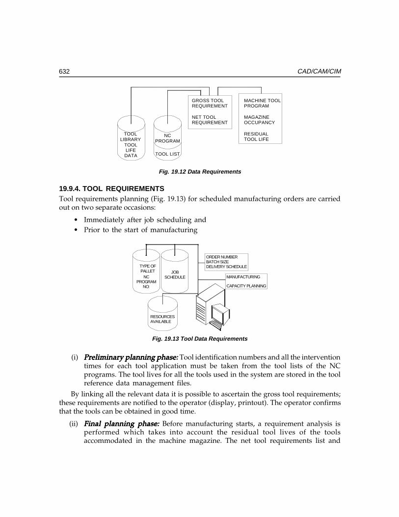
632 CAD/CAM/CIM
TOOL LIST
NCPROGRAM
GROSS TOOLREQUIREMENT
NET TOOLREQUIREMENT
MACHINE TOOLPROGRAM
MAGAZINEOCCUPANCY
RESIDUALTOOL LIFE
TOOLLIBRARY
TOOLLIFEDATA
Fig. 19.12 Data Requirements
19.9.4. TOOL REQUIREMENTSTool requirements planning (Fig. 19.13) for scheduled manufacturing orders are carriedout on two separate occasions:
• Immediately after job scheduling and• Prior to the start of manufacturing
TYPE OFPALLET
NCPROGRAM
NO:
JOBSCHEDULE
ORDER NUMBERBATCH SIZEDELIVERY SCHEDULE
MANUFACTURING
CAPACITY PLANNING
RESOURCES AVAILABLE
Fig. 19.13 Tool Data Requirements
(i) Preliminary planning phase: Preliminary planning phase: Preliminary planning phase: Preliminary planning phase: Preliminary planning phase: Tool identification numbers and all the interventiontimes for each tool application must be taken from the tool lists of the NCprograms. The tool lives for all the tools used in the system are stored in the toolreference data management files.
By linking all the relevant data it is possible to ascertain the gross tool requirements;these requirements are notified to the operator (display, printout). The operator confirmsthat the tools can be obtained in good time.
(ii) Final planning phase: Final planning phase: Final planning phase: Final planning phase: Final planning phase: Before manufacturing starts, a requirement analysis isperformed which takes into account the residual tool lives of the toolsaccommodated in the machine magazine. The net tool requirements list and
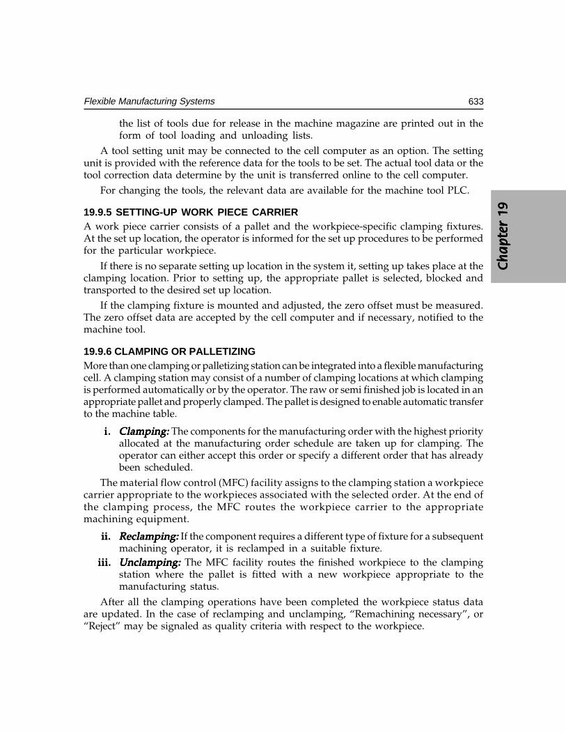
Ch
ap
ter
19C
ha
pte
r 19
Ch
ap
ter
19C
ha
pte
r 19
Ch
ap
ter
19
633Flexible Manufacturing Systems
the list of tools due for release in the machine magazine are printed out in theform of tool loading and unloading lists.
A tool setting unit may be connected to the cell computer as an option. The settingunit is provided with the reference data for the tools to be set. The actual tool data or thetool correction data determine by the unit is transferred online to the cell computer.
For changing the tools, the relevant data are available for the machine tool PLC.
19.9.5 SETTING-UP WORK PIECE CARRIERA work piece carrier consists of a pallet and the workpiece-specific clamping fixtures.At the set up location, the operator is informed for the set up procedures to be performedfor the particular workpiece.
If there is no separate setting up location in the system it, setting up takes place at theclamping location. Prior to setting up, the appropriate pallet is selected, blocked andtransported to the desired set up location.
If the clamping fixture is mounted and adjusted, the zero offset must be measured.The zero offset data are accepted by the cell computer and if necessary, notified to themachine tool.
19.9.6 CLAMPING OR PALLETIZINGMore than one clamping or palletizing station can be integrated into a flexible manufacturingcell. A clamping station may consist of a number of clamping locations at which clampingis performed automatically or by the operator. The raw or semi finished job is located in anappropriate pallet and properly clamped. The pallet is designed to enable automatic transferto the machine table.
i.i.i.i.i. Clamping: Clamping: Clamping: Clamping: Clamping: The components for the manufacturing order with the highest priorityallocated at the manufacturing order schedule are taken up for clamping. Theoperator can either accept this order or specify a different order that has alreadybeen scheduled.
The material flow control (MFC) facility assigns to the clamping station a workpiececarrier appropriate to the workpieces associated with the selected order. At the end ofthe clamping process, the MFC routes the workpiece carrier to the appropriatemachining equipment.
ii.ii.ii.ii.ii. Reclamping: Reclamping: Reclamping: Reclamping: Reclamping: If the component requires a different type of fixture for a subsequentmachining operator, it is reclamped in a suitable fixture.
iii.iii.iii.iii.iii. Unclamping:Unclamping:Unclamping:Unclamping:Unclamping: The MFC facility routes the finished workpiece to the clampingstation where the pallet is fitted with a new workpiece appropriate to themanufacturing status.
After all the clamping operations have been completed the workpiece status dataare updated. In the case of reclamping and unclamping, “Remachining necessary”, or“Reject” may be signaled as quality criteria with respect to the workpiece.
634 CAD/CAM/CIM
19.9.7 MATERIAL FLOW CONTROLThe material flow control facility controls and supervises the transport of the workpiececarriers with the clamped workpiece in the flexible manufacturing cell.
The workpiece carriers are transported by the transport system of the cell between asource station and a destination station. Source and destination station include clampinglocations, machine tools, washing and measuring machines, etc.
The transport requests are specified by the station-specific programs (e.g. machinetool program, fixturing programme) to the MFC facility at the end of an operation andprocessed by the MFC facility according to the FIFO principle (FIRST IN FIRST OUT).
In addition to the stations, each cell normally has storage locations where the workpiececan be held if the destination station is occupied.
If this happens the transport job together with the destination and the priority ispreserved. The source station identifier is replaced by the storage location number.
Information on the source and destination is obtained by interpreting the workpiece-specific schedule, in which among other things the sequence of operations is defined.
During transport the status data of the transport system, source and destination stations,workpiece carrier and workpiece are updated by the MFC facility in real time.
19.9.8 MACHINE TOOL PROGRAMIn the FMC system the machine tool program undertakes all the tasks arising at the interfaceto the machine tool. These tasks are online functions, so that each of the machine toolsintegrated into the FMC system is assigned its own machine tool program.
The machine tool programs process:
i.i.i.i.i. NC functionsNC functionsNC functionsNC functionsNC functions• Maintaining a list of the NC programs available in the CNC• Loading a program by preparing the CNC for loading and activating program
transfer via the NC program supply module• Erasing the CNC memory
ii.ii.ii.ii.ii. Tool dataTool dataTool dataTool dataTool data• Reading the tool magazine and forwarding the contents to the tool
requirement module• Forwarding the tool offset data on loading the tool magazine• Alarms and status messages which lead to the cancellation of automatic
processing of the machine tool.
Alarms and status messages are logged by the basic software system. The relevantstatus data are simultaneously updated.
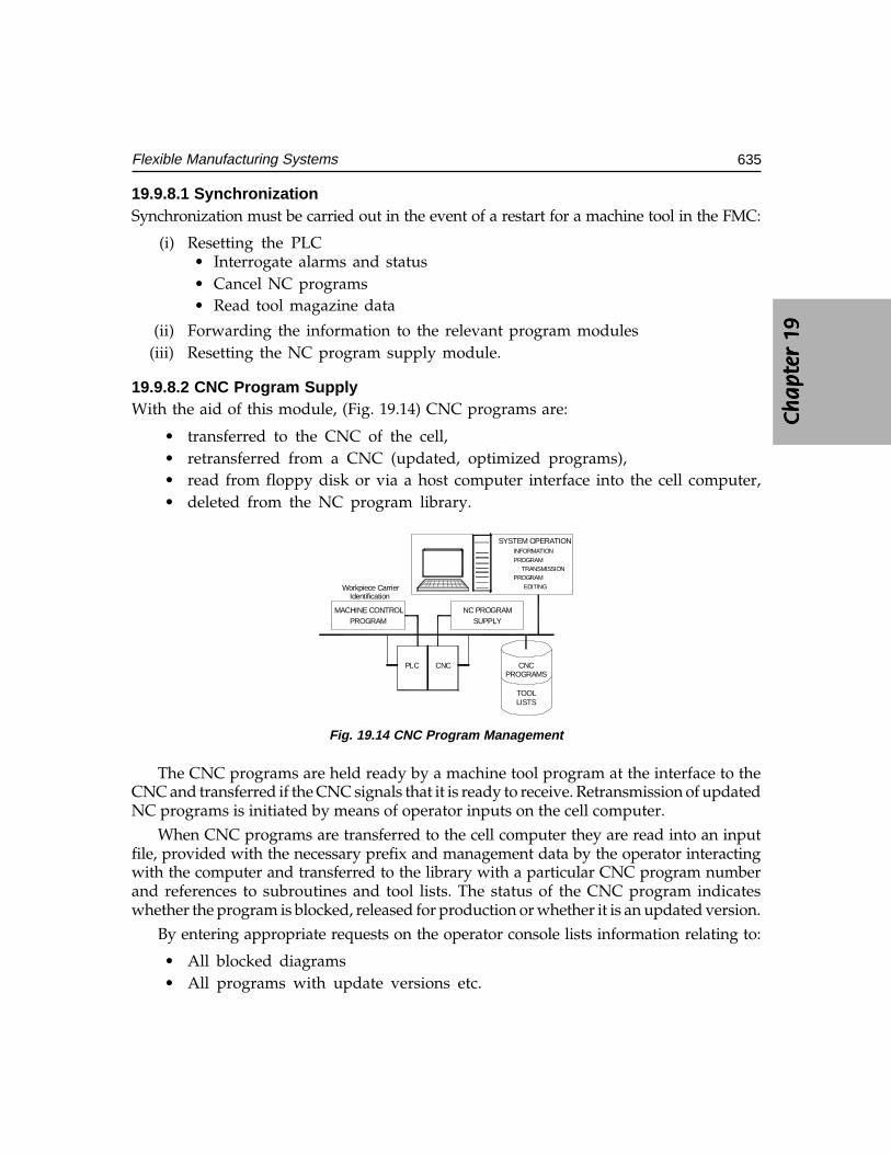
Ch
ap
ter
19C
ha
pte
r 19
Ch
ap
ter
19C
ha
pte
r 19
Ch
ap
ter
19
635Flexible Manufacturing Systems
19.9.8.1 SynchronizationSynchronization must be carried out in the event of a restart for a machine tool in the FMC:
(i) Resetting the PLC• Interrogate alarms and status• Cancel NC programs• Read tool magazine data
(ii) Forwarding the information to the relevant program modules(iii) Resetting the NC program supply module.
19.9.8.2 CNC Program SupplyWith the aid of this module, (Fig. 19.14) CNC programs are:
• transferred to the CNC of the cell,• retransferred from a CNC (updated, optimized programs),• read from floppy disk or via a host computer interface into the cell computer,• deleted from the NC program library.
CNCPROGRAMS
TOOLLISTS
SYSTEM OPERATIONINFORMATIONPROGRAM
TRANSMISSIONPROGRAM
EDITING
PLC CNC
NC PROGRAMSUPPLY
MACHINE CONTROLPROGRAM
Workpiece CarrierIdentification
Fig. 19.14 CNC Program Management
The CNC programs are held ready by a machine tool program at the interface to theCNC and transferred if the CNC signals that it is ready to receive. Retransmission of updatedNC programs is initiated by means of operator inputs on the cell computer.
When CNC programs are transferred to the cell computer they are read into an inputfile, provided with the necessary prefix and management data by the operator interactingwith the computer and transferred to the library with a particular CNC program numberand references to subroutines and tool lists. The status of the CNC program indicateswhether the program is blocked, released for production or whether it is an updated version.
By entering appropriate requests on the operator console lists information relating to:
• All blocked diagrams• All programs with update versions etc.
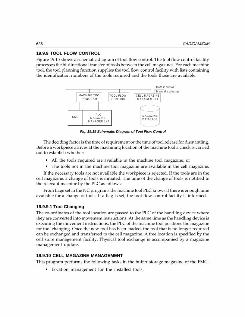
636 CAD/CAM/CIM
19.9.9 TOOL FLOW CONTROLFigure 19.15 shows a schematic diagram of tool flow control. The tool flow control facilityprocesses the bi-directional transfer of tools between the cell magazines. For each machinetool, the tool planning function supplies the tool flow control facility with lists containingthe identification numbers of the tools required and the tools those are available.
M AG AZIN EDATAB AS E
CE LL MA GA ZINEM AN A G EM E NT
Data input fo r
M anua l exchangeTOO L FLOW
CO N TRO LM AC HIN E TOO L
PR O G R AM
CN CPLC
M AG AZIN EM AN A G EM E NT
Fig. 19.15 Schematic Diagram of Tool Flow Control
The deciding factor is the time of requirement or the time of tool release for dismantling.Before a workpiece arrives at the machining location of the machine tool a check is carriedout to establish whether:
• All the tools required are available in the machine tool magazine, or• The tools not in the machine tool magazine are available in the cell magazine.
If the necessary tools are not available the workpiece is rejected. If the tools are in thecell magazine, a change of tools is initiated. The time of the change of tools is notified tothe relevant machine by the PLC as follows:
From flags set in the NC programs the machine tool PLC knows if there is enough timeavailable for a change of tools. If a flag is set, the tool flow control facility is informed.
19.9.9.1 Tool ChangingThe co-ordinates of the tool location are passed to the PLC of the handling device wherethey are converted into movement instructions. At the same time as the handling device isexecuting the movement instructions, the PLC of the machine tool positions the magazinefor tool changing. Once the new tool has been loaded, the tool that is no longer requiredcan be exchanged and transferred to the cell magazine. A free location is specified by thecell store management facility. Physical tool exchange is accompanied by a magazinemanagement update.
19.9.10 CELL MAGAZINE MANAGEMENTThis program performs the following tasks in the buffer storage magazine of the FMC:
• Location management for the installed tools,
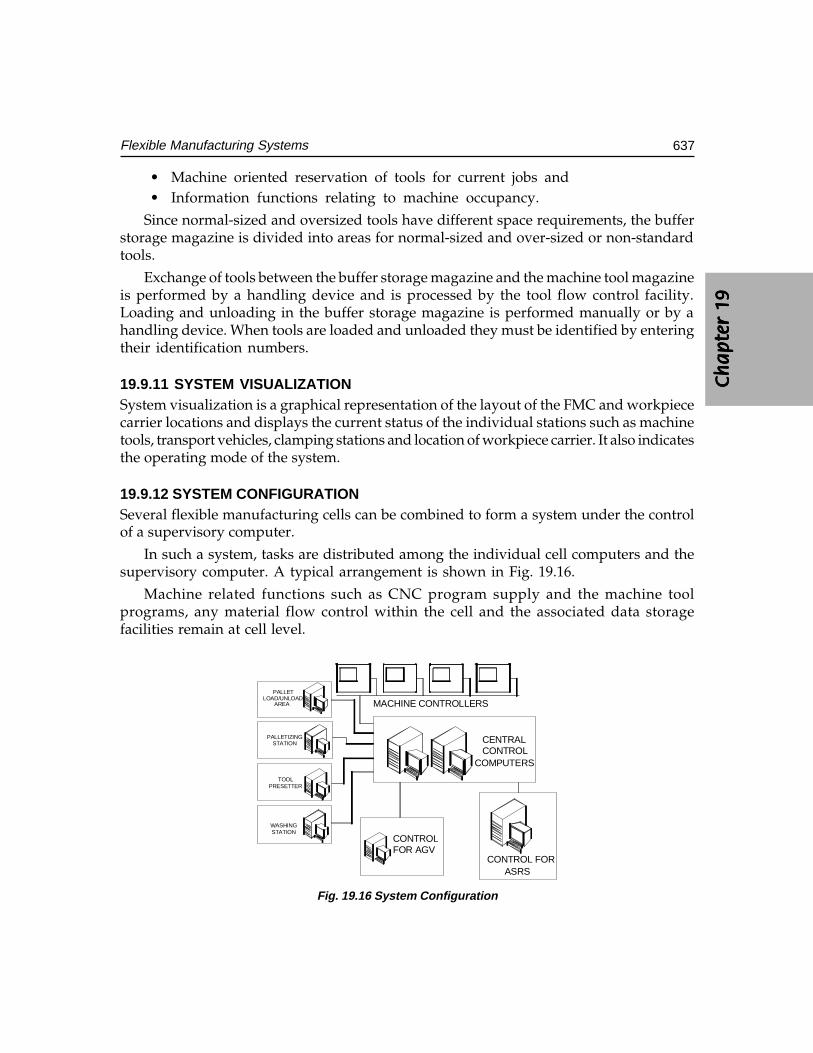
Ch
ap
ter
19C
ha
pte
r 19
Ch
ap
ter
19C
ha
pte
r 19
Ch
ap
ter
19
637Flexible Manufacturing Systems
• Machine oriented reservation of tools for current jobs and• Information functions relating to machine occupancy.
Since normal-sized and oversized tools have different space requirements, the bufferstorage magazine is divided into areas for normal-sized and over-sized or non-standardtools.
Exchange of tools between the buffer storage magazine and the machine tool magazineis performed by a handling device and is processed by the tool flow control facility.Loading and unloading in the buffer storage magazine is performed manually or by ahandling device. When tools are loaded and unloaded they must be identified by enteringtheir identification numbers.
19.9.11 SYSTEM VISUALIZATIONSystem visualization is a graphical representation of the layout of the FMC and workpiececarrier locations and displays the current status of the individual stations such as machinetools, transport vehicles, clamping stations and location of workpiece carrier. It also indicatesthe operating mode of the system.
19.9.12 SYSTEM CONFIGURATIONSeveral flexible manufacturing cells can be combined to form a system under the controlof a supervisory computer.
In such a system, tasks are distributed among the individual cell computers and thesupervisory computer. A typical arrangement is shown in Fig. 19.16.
Machine related functions such as CNC program supply and the machine toolprograms, any material flow control within the cell and the associated data storagefacilities remain at cell level.
PALLETLOAD/UNLOAD
AREA
PALLETIZINGSTATION
TOOLPRESETTER
WASHINGSTATION
MACHINE CONTROLLERS
CENTRALCONTROL
COMPUTERS
CONTROL FORASRS
CONTROLFOR AGV
Fig. 19.16 System Configuration
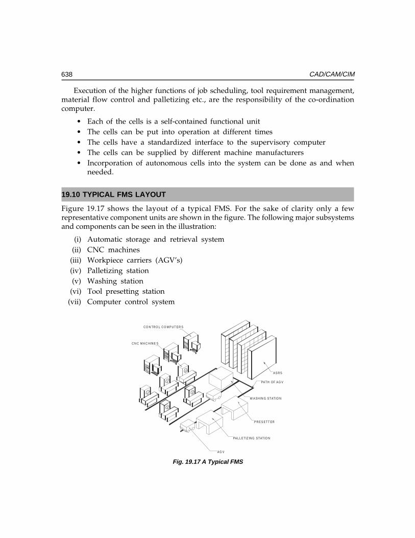
638 CAD/CAM/CIM
Execution of the higher functions of job scheduling, tool requirement management,material flow control and palletizing etc., are the responsibility of the co-ordinationcomputer.
• Each of the cells is a self-contained functional unit• The cells can be put into operation at different times• The cells have a standardized interface to the supervisory computer• The cells can be supplied by different machine manufacturers• Incorporation of autonomous cells into the system can be done as and when
needed.
19.10 TYPICAL FMS LAYOUT
Figure 19.17 shows the layout of a typical FMS. For the sake of clarity only a fewrepresentative component units are shown in the figure. The following major subsystemsand components can be seen in the illustration:
(i) Automatic storage and retrieval system(ii) CNC machines
(iii) Workpiece carriers (AGV’s)(iv) Palletizing station(v) Washing station
(vi) Tool presetting station(vii) Computer control system
C O N TR O L C O M P U T E R S
C N C M A C H IN E S
A G V
PA L L E TIZ IN G S TAT IO N
W A S H IN G S TAT IO N
P R E S E T T ER
PAT H OF A G V
A S R S
Fig. 19.17 A Typical FMS
Ch
ap
ter
19C
ha
pte
r 19
Ch
ap
ter
19C
ha
pte
r 19
Ch
ap
ter
19
639Flexible Manufacturing Systems
The automatic guided vehicle takes the palletized workpieces from the palletizingstation to the work centre. The guidance of the AGV is carried out through cables laidon the shop floor. The transfer of the palletized work from the AGV is effected througha special pallet changer device located in front of each of the machine tool.
19.11 FMS DEVELOPMENT IN INDIA
Because of the high cost in FMS, Indian manufacturers have not evinced much interestin the total adoption of this technology. The first unit of this type was established at theHeavy Alloy Penetrator Project (HAPP) at Trichy in South India during late 80’s. This unithas all the facilities of a FMS. Part of the equipment was manufactured at HMT and theinstallation of the factory was done by erstwhile HMT CIM division. Subsequently a numberof flexible turning cells have been set up by manufacturing industries in different partsof the country. FMS as a whole is not very popular today because of its high cost and thetime taken to design and install one. However, the principles of FMS are quite relevantand are being widely followed for achieving global competitiveness.
QUESTIONS
1. Discuss the need for flexibility in manufacturing in the present manufacturingscenario.
2. Compare FMS with transfer lines and CNC on the basis of volume and varietyof parts produced.
3. What is a FMC? How does FMC ensure flexibility in manufacturing?4. How does a turning centre differ from an FMC?5. Describe the essential elements of a flexible turning cell.6. Describe the additional subsystems that make a machining centre a flexible
machining system.7. What are the various innovations introduced in tooling for flexible manufacturing
systems?8. How is tool life monitored in FMS?9. Discuss the importance of in-process monitoring of workpiece quality in FMS.
10. What are the benefits of FMS?11. Discuss the relevance of FMS from the point of view of work centre utilization.12. Describe the principle of an automated storage and retrieval system.13. What are the major elements of FMS?14. Discuss the importance of materials handling system in FMS.15. Describe the types of materials handling devices used in a FMS.16. How is an FMS optimized?17. What are the different types of data associated with FMS?

640 CAD/CAM/CIM
18. How are jobs scheduled in FMS?19. Discuss the importance of palletizing.20. How is NC program management effected in a FMS?21. Discuss how the jobs are scheduled in a FMS.22. Sketch the layout of a typical FMS and explain the important subsystems.23. Compare the merits and demerits of a RGV and an AGV.24. Discuss tool management in relation to the operation of a FMS.
��������������
���� ���������� ��
���� �
Shop floor data collection systems play an important role in getting the feedback about theexecution of work on the shop floor. Whenever and wherever there is an action, some formof data is involved in that. Data collection equipment can be taken to that place and is usedto collect the data. These places of action can be a production line, a quality control station,a maintenance location or even an unattached operation such as warehouse conveyorsystem. This chapter deals with the techniques used to collect shop floor data.
20.1 INTRODUCTION
Monitoring the progress of the jobs is an integrated part of CIM. Collection of machinedata statistics, estimation of the non-production times and machine utilization, tracking offlow of materials, determination of job completion times and realization of schedules, etc.,are necessary to evaluate the efficiency of the functioning of the system. This requiresautomatic or direct data collection from the shop floor. The techniques and technologiesby which the status of production is collected are called shop floor data collection. Fig.20.1 illustrates various types of information/data to be collected from the shop floor.These include:
(i) Machine data(ii) Operator data
(iii) Tooling data(iv) Data relating to jobs to be done(v) Materials data
(vi) Materials handling data(vii) Scheduling data
(viii) Process planning data(ix) Inspection data
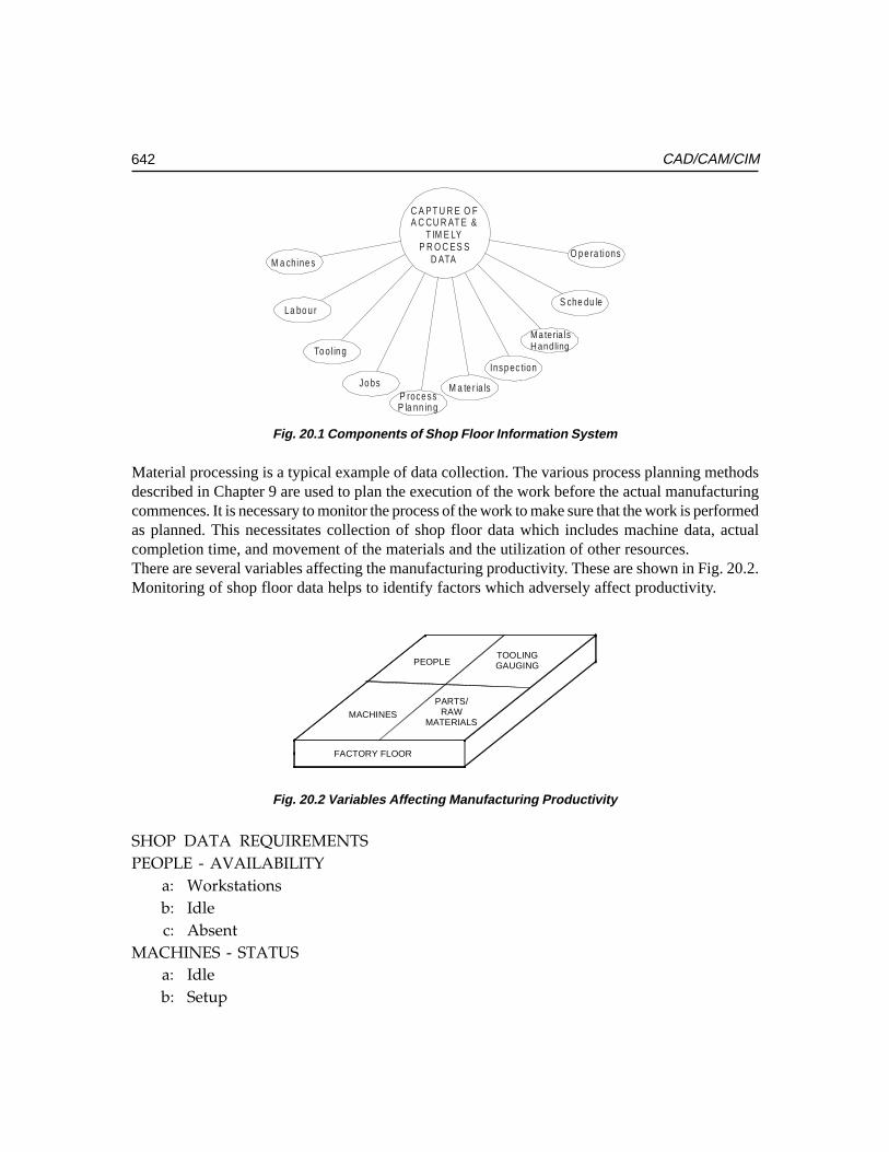
642 CAD/CAM/CIM
C A PT U R E O FA C CU R AT E &
T IM E LYP R O C ES S
D ATA O p e ra tions
S che du le
Insp ec tion
M a te r ia lsP roce ssP la nn in g
Jo bs
To ol in g
La bo u r
M a chine s
Ma teria lsH andling
Fig. 20.1 Components of Shop Floor Information System
Material processing is a typical example of data collection. The various process planning methodsdescribed in Chapter 9 are used to plan the execution of the work before the actual manufacturingcommences. It is necessary to monitor the process of the work to make sure that the work is performedas planned. This necessitates collection of shop floor data which includes machine data, actualcompletion time, and movement of the materials and the utilization of other resources.There are several variables affecting the manufacturing productivity. These are shown in Fig. 20.2.Monitoring of shop floor data helps to identify factors which adversely affect productivity.
PEOPLETOOLINGGAUGING
MACHINES
PARTS/RAW
MATERIALS
FACTORY FLOOR
Fig. 20.2 Variables Affecting Manufacturing Productivity
SHOP DATA REQUIREMENTSPEOPLE - AVAILABILITY
a: Workstationsb: Idlec: Absent
MACHINES - STATUSa: Idleb: Setup
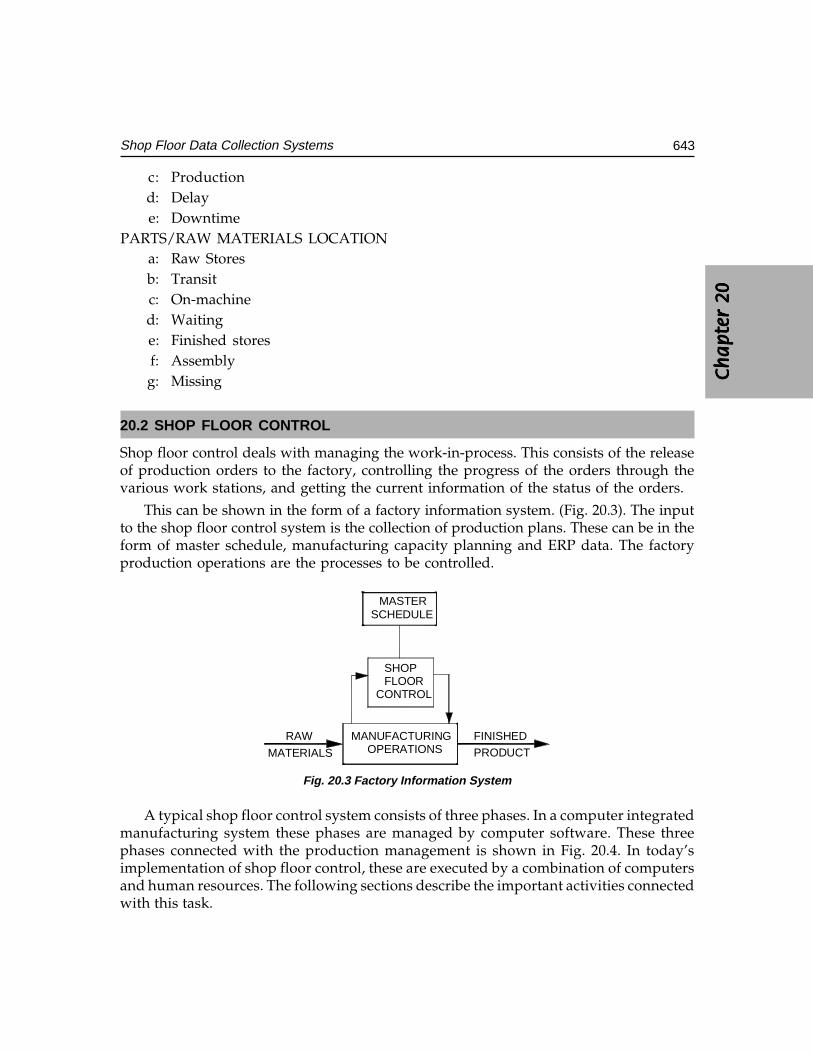
Ch
ap
ter
20C
ha
pte
r 20
Ch
ap
ter
20C
ha
pte
r 20
Ch
ap
ter
20
643Shop Floor Data Collection Systems
c: Productiond: Delaye: Downtime
PARTS/RAW MATERIALS LOCATIONa: Raw Storesb: Transitc: On-machined: Waitinge: Finished storesf: Assemblyg: Missing
20.2 SHOP FLOOR CONTROL
Shop floor control deals with managing the work-in-process. This consists of the releaseof production orders to the factory, controlling the progress of the orders through thevarious work stations, and getting the current information of the status of the orders.
This can be shown in the form of a factory information system. (Fig. 20.3). The inputto the shop floor control system is the collection of production plans. These can be in theform of master schedule, manufacturing capacity planning and ERP data. The factoryproduction operations are the processes to be controlled.
MANUFACTURINGOPERATIONS
RAW
MATERIALS
FINISHEDPRODUCT
SHOPFLOOR
CONTROL
MASTER SCHEDULE
Fig. 20.3 Factory Information System
A typical shop floor control system consists of three phases. In a computer integratedmanufacturing system these phases are managed by computer software. These threephases connected with the production management is shown in Fig. 20.4. In today’simplementation of shop floor control, these are executed by a combination of computersand human resources. The following sections describe the important activities connectedwith this task.
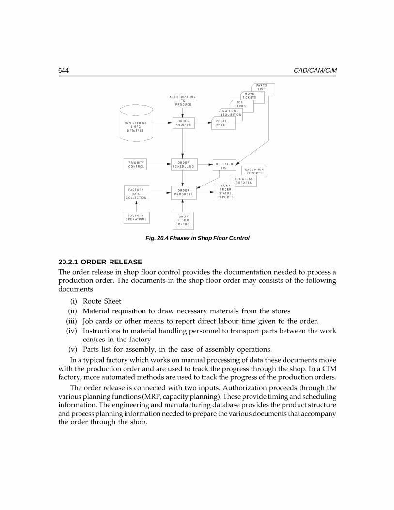
644 CAD/CAM/CIM
E N G IN E E R IN G& M F G
D ATA B A S E
P R IO R IT YC O N T R O L
F A C T O R YD ATA
C O L L E C T IO N
O R D E RR E LE A S E
O R D E RS C H E D U L IN G
O R D E RP R O G R E S S
S H O PF L O O R
C O N T R O L
F A C T O R YO P E R AT IO N S
R O U T ES H E E T
M AT E R IA LR E Q U IS IT IO N
J O BC A R D S
M O V ET IC K E T S
PA R T SL IS T
W O R KO R D E RS T AT U S
R E P O R T S
P R O G R E S SR E P O R T S
E X C E P T IO NR E P O R T S
D E S P AT C HL IS T
T OP R O D U C E
A U T H O R IZ AT I O N
Fig. 20.4 Phases in Shop Floor Control
20.2.1 ORDER RELEASEThe order release in shop floor control provides the documentation needed to process aproduction order. The documents in the shop floor order may consists of the followingdocuments
(i) Route Sheet(ii) Material requisition to draw necessary materials from the stores
(iii) Job cards or other means to report direct labour time given to the order.(iv) Instructions to material handling personnel to transport parts between the work
centres in the factory(v) Parts list for assembly, in the case of assembly operations.
In a typical factory which works on manual processing of data these documents movewith the production order and are used to track the progress through the shop. In a CIMfactory, more automated methods are used to track the progress of the production orders.
The order release is connected with two inputs. Authorization proceeds through thevarious planning functions (MRP, capacity planning). These provide timing and schedulinginformation. The engineering and manufacturing database provides the product structureand process planning information needed to prepare the various documents that accompanythe order through the shop.
Ch
ap
ter
20C
ha
pte
r 20
Ch
ap
ter
20C
ha
pte
r 20
Ch
ap
ter
20
645Shop Floor Data Collection Systems
20.2.2 ORDER SCHEDULINGThis module assigns the production orders to various work centres, machine tools, weldingstations, moulding machines etc., in the plant. It follows directly from the order releasemodule. Order scheduling executes the dispatch function in production planning andcontrol. The order scheduling module prepares a dispatch list that indicates whichproduction order should be accomplished at the various work centres. It provides theinformation on the relative priorities of the various jobs by showing the due dates for eachjob. By following the dispatch list in making work assignments and allocating resources todifferent jobs the master schedule can be best achieved.
The order schedule module addresses to two important activities in shop floorproduction control.
(i) Machine loading(ii) Job sequencing.Allocating the orders to the work centres is termed as machine loading or shop loading,
which refers to the loading of all machines in the plant. In most cases each work centre willhave a queue of orders waiting to be processed. This queue problem can be solved by jobsequencing. This involves determining the order in which the jobs will be processed througha given work centre. To determine this sequence, priorities are given to jobs in the queueand the jobs are processed according to the priorities. Several queuing models are availablein operations management to solve this problem.
This control of priorities is an important input to the order scheduling module. Rulesto establish the priorities are:
(i) Earliest due date: These are given high priority(ii) Shortest processing time: Shorter processing time orders are given high priority.
(iii) Least slack time: Orders with least slack time are given high priority.Fluctuations in market demand, equipment breakdown, cancellation of the order by
customer and defective raw material or delay in the receipt of materials affect the priority.The priority control plan reviews the relative priorities of the orders and adjusts the dispatchlist accordingly.
20.2.3 Order ProgressThe order progress module in the shop floor control system monitors the status of thevarious orders in the plant work-in-process and other characteristics that indicate theprogress and performance of production. The function of the order progress module is toprovide the information that is useful in managing the factory based on the data collectedfrom the factory. The order progress report includes:
(i) Work order status reports:Work order status reports:Work order status reports:Work order status reports:Work order status reports: These reports indicate the status of the productionorders. Typical information in the report includes the current work centre whereeach order is located, processing hours remaining before completion of eachorder, whether the job is on-time or behind schedule, and priority level.
646 CAD/CAM/CIM
(ii) Progress report:Progress report:Progress report:Progress report:Progress report: A progress report records the performance of the shop duringthe period of master schedule and reports the number of operations completedand not completed during the time period.
(iii) Exception reports:Exception reports:Exception reports:Exception reports:Exception reports: These reports bring out the deviations from the productionschedule (ex. overdue jobs).
The above reports are useful to production management in making the decisions aboutallocation of resources, authorization of the overtime hours, and other capacity issues, andin identifying areas of problems in the plant that adversely affect the implementation ofthe master production schedule.
20.3 SHOP FLOOR DATA COLLECTION
There are several of data collection techniques to gather data from the shop floor. Someof the data are keyed by the employees and the rest are recorded automatically. Laterthe data is compiled on a fully automated system that requires no human intervention.These methods are collectively called as shop floor data collection systems.
These data collection systems consist of various paper documents, terminals andautomated devices located through the plant in a plant. The shop floor data collectionsystem serves as an input to the order progress module in shop floor (Fig.20.4).
Examples of the data collection in shop floor are:
(i) To supply data to the order progress module in the shop floor control system.(ii) To provide up to date information to the production supervisors and production
control personnel.(iii) To enable the management to monitor implementation of master schedule.
To carry out this, the factory data collection system inputs the data to the computersystem in the plant.
20.4 TYPES OF DATA COLLECTION SYSTEMS
The shop floor data collection systems can be classified into two groups.
(i) On-line data collection systems(ii) Off-line data collection systems
20.4.1. ON-LINE DATA COLLECTION SYSTEMSIn an on-line system, the data are directly entered to the computer and are available to theorder progress module. The advantage lies in the fact that the data file representing thestatus of the shop is always at the current state. As and when the changes in the orderprogress module are reported they can be fed to computer and in turn to the status file. Inthis way the production personnel are provided with most up-to-data information.
Ch
ap
ter
20C
ha
pte
r 20
Ch
ap
ter
20C
ha
pte
r 20
Ch
ap
ter
20
647Shop Floor Data Collection Systems
20.4.2 OFF-LINE (BATCH) DATA COLLECTION SYSTEMSIn this the data are collected temporarily in a storage device or a stand alone computersystem to be entered and processed by plant computer in a batch mode. In this mode thereis delay in the entry and processing of the data. The delay may vary depending upon thesituation. So this system cannot provide real time information of shop floor status. Theadvantage of this system is that it is easier to install and implement.
20.5 DATA INPUT TECHNIQUES
As stated earlier, the data collection techniques include manual procedures and computerterminals located on the shop floor. The manual data collection methods require theproduction workers to fill out paper forms indicating order progress data. These forms arecompiled using a combination of clerical and computerized methods.
The manual data collection methods rely on the co-operation and clerical accuracy ofthe employees to record a data property on a proper document. Errors may creep in thistype of method. The common forms of errors that can be checked and rectified are wrongdates, incorrect order numbers and incorrect operation numbers. These can be detectedand corrected. There are, however, other errors which are difficult to identify.
Another problem is that there may be a delay in submitting the order progress forcompiling. The reason is that there will be always a time lapse between when occurrenceof events and recording of events.
These problems necessitate the location of the data collection equipment in the factoryitself. The various input techniques include manual input by push-button pads orkeyboards. Error checking routines can be incorporated to detect the syntax errors in theinput. The data entry methods also include more automated technologies, such as barcode reader, magnetic card readers etc.
An important type of equipment used in shop floor data entry is keyboard basedsystems. There are various types of such systems. They are discussed in thefollowing sections.
20.5.1 CENTRALIZED TERMINALA single terminal is located centrally in the shop floor. This requires the employees to go tothe terminal and input the data. So employee’s time will be wasted and in a big shop, thisbecomes inconvenient.
20.5.2 SATELLITE TERMINALSThese are multiple data collection centres located throughout the shop floor. In thisarrangement a balance is to be struck between the minimization of the investment cost andmaximization of the convenience of the employees in the plant.
648 CAD/CAM/CIM
20.5.3 WORK CENTRE TERMINALSThe most convenient arrangements to the employees are to have a data collection terminalat each work centre. This reduces the time to go to the central terminal. This can be appliedwhen the amount of data to be collected is very large.
20.6 AUTOMATIC DATA COLLECTION SYSTEM
The recent trend in industry towards use of more automation necessitates putting inplace automated data collection methods. Although the term automatic is used here,human participation is unavoidable in many cases.
The advantages of the automatic data collection methods are:
(i) The accuracy of data collected increases(ii) The time required by the workers to make the data entry can be reduced.
The basic elements in data collection systems are:
(i) Machine readable media(ii) Terminal configuration
(iii) Software for data collection.
20.6.1 MACHINE READABLE MEDIATypical machine readable media include:
(i) Bar Code Technology(ii) Optical Character Recognition (OCR)
(iii) Magnetic Ink Character(iv) Voice Recognition (VR)(v) Magnetic Strip Technology
(vi) Smart Cards
20.7 BAR CODE TECHNOLOGY
Bar code technology is primarily an automatic identification technique. The data is simplyreduced to a printed form, which consists of a symbol made of successive line segments. Abar code reader is used to illuminate the bar code symbol and examine successive segmentsof the symbol. The detected area may be a highly reflected area (space) or a non-reflective(bar). As the reader moves reader over the bar code symbol, due to reflectivity and non-reflectivity, alternate transitions from light to dark and dark to light occur. These are detectedand the time it will take will be converted to digital representations of ones and zeros ofthe bar code messages. Most commonly used bar codes are:
Ch
ap
ter
20C
ha
pte
r 20
Ch
ap
ter
20C
ha
pte
r 20
Ch
ap
ter
20
649Shop Floor Data Collection Systems
(i) Universal Product Code (UPC)(ii) Interleaved 2 of 5 (ITF)
(iii) Code 39
There are two types of bar code readers. They are classified as:
(i) Fixed Beam Reader(ii) Moving Beam Reader
20.7.1 FIXED BEAM READERBar code readers are either fixture mounted or hand held. The simplest form of bar codereader is a light pen. The tip of the light pen is moved in contact with the symbol andmoves the tip from leading zone through trailing zone in a smooth sweeping motion.The fixed beam light pen nearly or actually touches the symbol.
In fixture mounted reader the beam reader is fixed and the symbol moves. The readeris mounted on a conveyor or a transport system, observing a symbol while it passes througha reader beam. The fixed beam reader reads the symbol only once. In hand-held fixedbeam reader the symbol can be rescanned easily. In the fixture mounted bar code readersome mechanism which moves the symbol towards the symbol is necessary i.e., anintervention by operator is needed.
In fixed beam reader the contact with the symbol may erase the symbol and so it is lessreadable in subsequent attempts to read the symbol. Contact scanning of the symbol requiresa smooth surface. So it is not suitable to read all the surfaces on which the symbols are printed.
Light pens interpret a narrow section of the symbol printed on a surface. This maycause the distortion of the image. Fixed beam reader takes more time to read the symbol.Speed of fixed beam readers is a function of conveyor speed and height of the bar codesymbol. Faster scanners are required for shorter symbols and slower scanners are requiredfor larger symbols.
20.7.2 MOVING BEAM READERThese minimize limitations of the fixed beam reader i.e., intervention problem and contactwith the symbol. Moving beam reader, as the name indicates, scans the symbol by a line oflight emitted from the reader. This is actually a spot which moves at faster rates appearingas a straight line. A moving beam reader takes less time to scan the symbol depending onthe type of equipment.
The light emitted from the moving beam reader can be drawn through the symbol inboth the configurations i.e., hand held and conveyor configurations. Multiple viewing of thesymbol provides quick and correct information to convert the image to computer data.
20.7.3 ELEMENTS OF BAR CODE READERSThe hardware of a bar code reader consists of a detector and a light source.
650 CAD/CAM/CIM
(i) All fixed, moving beam readers will have a single detector which samples verysmall areas of the symbol. The detector used is linear charge coupled device.These employ a line of detectors which takes a snap shot of the symbol andprojects the image on photo sensitive device. Then the detector is amplified toknow whether it has observed a space or a bar. This is applied for a bar codeof maximum length of 5 cm or less. This cannot be used for larger bar codes.A matrix charge coupled device has a matrix of detectors (64 pixels long and 64
pixels high). These can be used either hand held or moving configurations or eliminatesthe problems associated with the voids, spots and edge roughness of the code. These canbe used to detect long narrow bars as well as wide bars.
(ii) The light source employed in a bar code reader to illuminate the symbol maybe a red light or infrared light.
Red light is obtained from Helium-Neon lamp transmitting at 633 nanometres. Theproblem associated with this is that red and white colors appear to be same for the detector.Infrared light source operates at 900 nm and is invisible to the human eye but can bedetected by the photo detector. Limitations of this type are the ink used to print bar codeshould have high carbon content.
A light source which operates at 800 nm or nearly infra red range will be able to readdye and colour based inks having high carbon content.
The cost of bar code system depends on the manufacturing facility. If the samemanufacturing organization is printing and reading the symbol, the cost may be less.
20.8 OPTICAL CHARACTER RECOGNITION
The optical character recognition (OCR) employs special fonts which can be read byman and machine. This is more reliable than key entry but less reliable compared to barcode technology.
OCR fonts or characters are ‘read’ by software template techniques or feature extractionor combination of both. So each character is to be unique compared to other characters inthe set.
When a number of pages of data are to be input to a computer system, optical pagereaders are very useful. Optical page readers are similar to the office copiers. In OCR,entire page is to be scanned before next page is presented to the reader. The characters ina page are identified by the reader by the specific font styles and sizes.
In OCR, the reading device is to be passed over the OCR character a number of times.Here, the reader must be precisely positioned over the string which is to be read. Theposes a problem when long strings of information are to be read. OCR is very sensitive tothe motion of the operator’s hand during reading. OCR can not read the symbols on themoving objects. To read the information on the moving objects a strobe light is to besynchronized with object.
Ch
ap
ter
20C
ha
pte
r 20
Ch
ap
ter
20C
ha
pte
r 20
Ch
ap
ter
20
651Shop Floor Data Collection Systems
OCR techniques identify the horizontal and vertical strokes, curves and endingspeculiar to each character. The absence of vertical redundancy and repeating characterpattern causes OCR to be prone to errors. These are caused by poor print quality andthose introduced through scanning process.
20.9 MAGNETIC INK CHARACTER RECOGNITION
Magnetic Ink Character Recognition (MICR) uses stylized OCR fonts. The fonts areprinted with a magnetic ink to permit readability after being overprinted or evensmudged. MICR is used to read smaller documents of size 7 to 20 cm. Like OCR, thesealso require precise orientation and registration.
20.10 VOICE RECOGNITION
Speech is the most natural way of communication. This eliminates the need of the userto understand a computer system. Voice technology is intelligently packaged and appliedin several applications. Moreover the training can be minimized and the key board entrycan be eliminated and hand and eye co-ordination is no longer needed.
Voice recognition (VR) is of two types:
(i) Speaker dependent(ii) Speaker independent
Most voice recognition systems are speaker independent systems. VR systemsrecognize the user’s vocabulary and store a computer image of each utterance andcompare later the input words to the computer stored words. If the input matches thestored pattern, recognition is achieved. This provides larger vocabulary and accuraterecognition. Commercial VR systems are having around a few hundred words in activevocabulary and skilful programming can develop application dependent vocabularies.
Real application of VR systems rests on the fact that user need not be trained to usethe system. Speaker independent system uses recognition template from memories ofthe previously recorded images. The templates represent speech patterns of both maleand female speakers. These are now available with limited vocabularies.
20.11 SMART CARDS
Smart cards are made of plastic. They are of the size of a credit card and are embeddedwith one or more microchips. These have an 8-bit or higher level microprocessors and willhave a storage capacity of about 8 kB. Recent cards can carry up to 256 kB with the contactsremoved and integrated with keypads. Personal identification numbers (PIN) preventunauthorized use of smart cards.
652 CAD/CAM/CIM
20.12 DATA ACQUISITION SYSTEMS (DAS)
The trend in shop floor data collection is towards the more use of the automated systems.Some of the bar code reading methods and other automatic identification methods discussedearlier can be operated in a fully automated mode.
Computer process monitoring system involves a computer which is directly connectedwith the manufacturing process for the purpose of collecting the data on the process andthe equipment.
The hardware components of the computer process monitoring system used to inputthe data from the process are sensors and transducers, analog-to-digital converters, limitswitches and photo detectors, pulse generators etc.
A data acquisition system is a computer system used to collect the data from a processor piece of equipment. These perform an analysis of data or transmit the data to anothercomputer for processing and analysis. A microprocessor is used as the controller/processorin a DAS. Other controllers use minicomputers or single board computers. The function ofthe controller/processor is to synchronize the data sampling and storage and tabulatedata for presentation and statistical and other analysis.
Components of DAS include analog transducers, Analog-to-digital converters, digitaltransducers, and digital input interfaces.
Separate data acquisition modules are often attached with FMS elements to enableoperation to send status information to the control computer.
QUESTIONS
1. Discuss the need and importance of shop floor data collection systems. What aretheir functions?
2. What are the major types of data collection systems?3. What are the devices used for shop floor data collection?4. How does a bar code reader work?
������������
�������� ��
������
The need to reduce time to market requires that costly iterations in product developmentshould be avoided. This means that the manufacturing engineers have to do every job rightfirst time every time. Manufacturing simulation is one way of ensuring that the process ismodeled and tested before the manufacture commences. Some details of this technologyare discussed in this chapter.
21.1 INTRODUCTION
Simulation in manufacturing refers to a broad collection of computer based applicationsto imitate the behavior of manufacturing systems. A system is a facility or a process eitheractual or planned such as factory with workers, machine tools, materials handling devices,storage devices etc. Simulation is intended to study the model of this real world system bynumerical evaluation using software. Simulation is carried out to evaluate the performanceof a system, product or process before it is physically built or implemented. Simulationwas discussed in this book earlier in different contexts- design simulation using finiteelement technique, manufacturing process simulation also using finite element technique,simulation of robots and simulation of CNC machines. Another type of simulation, whichhas become very popular of late, is manufacturing or factory simulation. Factory simulationinvolves creating a virtual factory. Here, instead of simulating a process or a work centrethe entire factory is simulated to have a clear understanding of the working of the plant asa whole.
Simulation technology holds tremendous promise for reducing costs, improving quality,and shortening the time-to-market for manufactured goods. In the present context,simulation refers to the study of the performance of a manufacturing system or a factory.Simulation involves modeling and visualization of the entire plant. There are severalpotential benefits from simulation. But lack of understanding, cost of software and expertisehave made simulation not popular with manufacturing engineers, till recently.
The development and maintenance of simulation models of manufacturing equipmentcan be costly. For example, let us take the case of a machine shop. A detailed simulation
654 CAD/CAM/CIM
model of a single machine tool may take an engineer several weeks to create, and suchcustomized models are required for each type of machine tool. However, standardreusable simulation model codes are now available which reduces the time involved increating the model.
Today, computer-based simulation is inexpensive and effective. Simulation makes iteasier to evaluate production cells or systems before implementing them. It allows errorsor deficiencies to be identified and corrected before they are implemented. Models can bebuilt, tested and compared for different design variations. ‘What-if’ analysis can then becarried out either to choose the best design or layout or product mix. Extensive simulationstudies can be carried out to evaluate the performance of a manufacturing system, undervarious input and operating conditions as well as under different plant configurationsand capacities.
Simulation helps to meet the objective of bringing products to the market faster becauseit does not require the time-consuming activities of building physical models of the plant.Instead it uses the models designed in the computer, which would normally be the basisfor building the physical models. Building physical models of plants is not practical andeven if made, they are not suitable for simulation purposes. Thus, time is saved because itis not necessary to build the ‘physical’ model. In addition, even more time is saved asmodifications could be made to the computer-based model to improve the performance ofthe plant and the simulation is repeated as a “what if” case.
In addition to usual applications like system design and performance estimation,simulation can also be used for scheduling. The simulation software in this case gathersthe required data from manufacturing execution system and generates multiple schedulesfrom which optimum could be selected.
21.2 TYPES OF SIMULATION
Simulation could be classified into three types.
i. Static or dynamic simulation:Static or dynamic simulation:Static or dynamic simulation:Static or dynamic simulation:Static or dynamic simulation: In static simulation time does not have a role.However, most of the manufacturing systems are time dependent and are hencedynamic.
ii. Continuous or discrete:Continuous or discrete:Continuous or discrete:Continuous or discrete:Continuous or discrete: A continuous system is one which continuously varieswith time. Examples are refinery, thermal power plant and plate glassmanufacturing plant where production is continuous but may fluctuate overtime. An automotive assembly plant is more or less a continuous system. On theother hand, a company manufacturing machine tools, motors, pumps, is a discretesystem. A Job shop where batch quantity may vary from one to many is anotherexample of a discrete manufacturing plant. In some cases, the manufacturingsystem may be a combination of both discrete and continuous system. Such asystem may be called mixed continuous-discrete system. Discrete event simulationis a powerful tool in manufacturing. The advantage of the simulation model is
Ch
ap
ter
2C
ha
pte
r 2
Ch
ap
ter
2C
ha
pte
r 2
Ch
ap
ter
2 1111 1
655Simulation in Manufacturing
that it can be reused for a different problem or to evaluate another option. Inthe globalization era, engineers should be capable of responding faster todynamically changing global markets and simulation helps to reduce the timeto market.
iii. Deterministic or stochastic:Deterministic or stochastic:Deterministic or stochastic:Deterministic or stochastic:Deterministic or stochastic: Systems which have no random inputs aredeterministic. A design bureau or a rapid prototyping shop may receive ordersat random. Several fabrication companies may also fall under this category. Amanufacturing system may also have both deterministic and random inputs.
21.3 TECHNIQUES OF SIMULATION
Simulation can be carried out in three ways.
i. Programming in general purpose simulation languagesii. Simulation using simulation languages
iii. High level simulators
These are briefly explained in the subsequent sections.
21.3.1 SIMULATION USING GENERAL PURPOSE LANGUAGESSimulation programs can be written in high level languages like FORTRAN or C. Thisapproach was popular when simulation languages where not available. The advantageof this approach is the opportunity to design the system to a specific application in acustomized manner. However, the process is tedious, time consuming and error prone.
21.3.2 SIMULATION LANGUAGESGeneral Purpose Simulation System (GPSS) is one language popularly used for simulation.GPSS is a family of mostly-declarative languages designed for discrete-event simulationand system modeling. A GPSS simulation program consists of a set of blocks which includegenerators, queues, servers, selectors or routers, data collectors, timing and computationalnodes. Data types supported in simulation models vary between versions, but usuallyinclude integers, real numbers, strings, and records. GPSS systems always had sophisticatedrandom sample generators to model various probability distributions that to model real-world processes. SIMSCRIPT, SLAM, SIMAN etc were later developed and became popularwith manufacturing industry. These are very flexible to simulate variety of systems.
21.3.3 HIGH-LEVEL SIMULATORSHigh level simulators differ from the simulation languages as the latter feature in additionpowerful graphics user interfaces, menus and dialog boxes. Standard constructs enablethe user to model a system quickly. This makes model creation faster. However, there isa trade off in flexibility. The facility for dynamic graphic animation gives the user tovisualize the actual working of the system.
656 CAD/CAM/CIM
21.4 SIMULATION PROCESS FOR MANUFACTURING SYSTEMS ANALYSIS
The process of simulating a manufacturing system involves the following steps.
i. Model design:Model design:Model design:Model design:Model design: In this step the issues to be addressed are identified based onwhich the project is planned. Next step is to develop a conceptual model.
ii. Model development:Model development:Model development:Model development:Model development: The simulation engineer chooses a modeling approachsuitable for the problem. After building the model it is tested to verify andvalidate the model.
iii. Model deployment:Model deployment:Model deployment:Model deployment:Model deployment: The model is used to carry out experiments like ‘What if”analysis. The results are then studied and used for making decisions.
21.5 SIMULATION SOFTWARE PACKAGES
There are a number of simulation packages in use today. Some of them are listed below:
• Analytica• Arena• Automod• Autoshed• @risk• Crystal Ball• eM Plant• Enterprise Dynamic Simulation Software• Enterprise Dynamic Simulation studio• Extend OR• Extend Suite• FlexSim• GPSS• GoldSim• Lean_modeler• MAST• Process Simulator• Pro Model• PSM+++• SAIL• Show Flow 2• SIGMA• SIMAN
Ch
ap
ter
2C
ha
pte
r 2
Ch
ap
ter
2C
ha
pte
r 2
Ch
ap
ter
2 1111 1
657Simulation in Manufacturing
• SIMPROCESS• SIMSCRIPT II.5• SIMUL8• SLIM• Supply chain Guru• Visual Simulation Environment• Web GPSS• Witness 2006• XLSim
Standardized interfaces, component model libraries, and modeling techniques havereduced the cost and increased the accuracy and accessibility of manufacturing simulationtechnology. Simulation is commonly used manufacturing system design and improvementmethods such as lean manufacturing and six sigma.
21.6 APPLICATION OF SIMULATION
Simulation has been widely used in the manufacturing industry to optimize the designof the shop floors and tailor the facility to yield the required output. It is also used topredict the output under various input and operating conditions. Automotive industryand aerospace industry are the major industries, which make use of simulation. Thefollowing sections give brief details of how simulation is used in industries.
21.6.1 SIMULATION IN AUTOMOTIVE INDUSTRYThe automotive industry uses discrete event simulation to investigate the capabilities ofthe different manufacturing shops involved in building automobiles like body shops, paintshops, trim/chassis/final assembly shops, and engine assembly shops, machining shopsand stamping shops.
Simulation of body shop systems during the concept, design and build phases of aproduct life cycle allows an automotive company to investigate the impact of tooling,conveyor and material delivery systems on the throughput.
There are two different approaches adopted to analyze the performance of a bodyshop. The first is to model the body shop at the station level. The second approach is tomodel the body shop at the line or subassembly level of detail.
The station-level simulation model is used to analyze the stand alone capability of asubassembly area. Station cycle times and downtimes are entered into a simulation modeland the subassembly throughput is estimated. The subassembly throughput can becompared directly to the body shop target throughput. As a general rule, the subassemblythroughput must be greater than the full body shop throughput or new design of thesubassembly area would be needed. If complex manual operations occur at a station, these
658 CAD/CAM/CIM
operations can be added to the station level model. Modeling the walk, pickup and setdown times can identify if an individual station can meet the required cycle time for thesubassembly area.
While the station-level analysis of the subassembly areas is being carried out, a linelevel model can be developed. The throughput estimates from the individual subassemblymodels are entered into the line level model and the conveyor systems are modeled indetail. The interaction between the subassemblies and the conveyor systems can be usedto identify sets of subassemblies or individual subassemblies to identify the bottlenecks inthe body shop. Sizing of the conveyor can be accomplished by increasing buffer betweenbottleneck subassembly areas and reducing buffer between non-bottleneck areas. Thisprocess continues through the design phase.
An alternative to this approach is to integrate all of the subassembly models into onelarge detailed model. Any time a subassembly changes or the conveyor layout changes,the model is updated to analyze the full body shop system.
The full body shop model is also used to investigate the impact that operationalparameters have on the system once it is implemented. The operational parameters caninclude: preventative maintenance, reducing mean time to repair, batch sizing, andovertime. Changing operational parameters and identifying their impact on systemperformance will show the opportunities for increasing system performance and will aidin the prioritization of funding.
An additional analysis that occurs in the body shop is the delivery of materials to theline locations. This analysis investigates the impact of the number of fork lift trucks, forklift truck assignments, the amount of stock at the line, the location of storage areas, thelocations of docks, and the number of docks on delays caused by parts not present at theline. In the concept phase, this analysis can influence the location of subassemblies andidentify strategic locations for stock to minimize the material delivery times.
When automotive paint shops are simulated, the focus is usually on the power-and-free conveyor systems that transport parts through the painting operations. Power-and-free systems are different from other conveyors because of carriers that fixthemselves to the drive chain by means of a hooking mechanism called a dog. Whentwo different speed chains merge, carriers can accumulate and are picked up by thedogs on the new chain. There are two types of chains: low speed production chainsused while parts are being painted and high speed transport chains, which move partsbetween different production areas.
During the design phase of a paint system, the power-and-free layout is evaluatedusing simulation to determine if throughput targets can be met. Power-and-free systemsmay require kilometers of production and transport chain to connect different sub-systemsto transport parts. Simulation is used to determine the number of carriers required, howchain merges and transfers will operate and whether adequate accumulation is provided.In some areas where higher density empty carrier storage is required, carriers are rotated
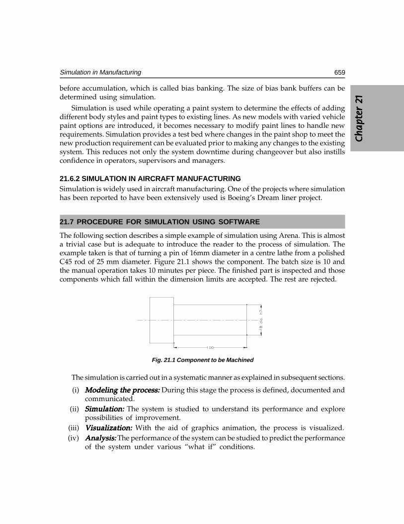
Ch
ap
ter
2C
ha
pte
r 2
Ch
ap
ter
2C
ha
pte
r 2
Ch
ap
ter
2 1111 1
659Simulation in Manufacturing
before accumulation, which is called bias banking. The size of bias bank buffers can bedetermined using simulation.
Simulation is used while operating a paint system to determine the effects of addingdifferent body styles and paint types to existing lines. As new models with varied vehiclepaint options are introduced, it becomes necessary to modify paint lines to handle newrequirements. Simulation provides a test bed where changes in the paint shop to meet thenew production requirement can be evaluated prior to making any changes to the existingsystem. This reduces not only the system downtime during changeover but also instillsconfidence in operators, supervisors and managers.
21.6.2 SIMULATION IN AIRCRAFT MANUFACTURINGSimulation is widely used in aircraft manufacturing. One of the projects where simulationhas been reported to have been extensively used is Boeing’s Dream liner project.
21.7 PROCEDURE FOR SIMULATION USING SOFTWARE
The following section describes a simple example of simulation using Arena. This is almosta trivial case but is adequate to introduce the reader to the process of simulation. Theexample taken is that of turning a pin of 16mm diameter in a centre lathe from a polishedC45 rod of 25 mm diameter. Figure 21.1 shows the component. The batch size is 10 andthe manual operation takes 10 minutes per piece. The finished part is inspected and thosecomponents which fall within the dimension limits are accepted. The rest are rejected.
Fig. 21.1 Component to be Machined
The simulation is carried out in a systematic manner as explained in subsequent sections.
(i) Modeling the process: Modeling the process: Modeling the process: Modeling the process: Modeling the process: During this stage the process is defined, documented andcommunicated.
(ii) Simulation:Simulation:Simulation:Simulation:Simulation: The system is studied to understand its performance and explorepossibilities of improvement.
(iii) Visualization:Visualization:Visualization:Visualization:Visualization: With the aid of graphics animation, the process is visualized.(iv) Analysis:Analysis:Analysis:Analysis:Analysis: The performance of the system can be studied to predict the performance
of the system under various “what if” conditions.
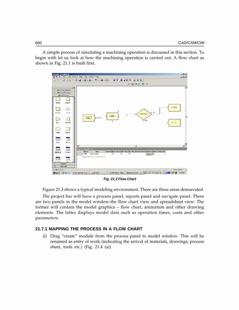
660 CAD/CAM/CIM
A simple process of simulating a machining operation is discussed in this section. Tobegin with let us look at how the machining operation is carried out. A flow chart asshown in Fig. 21.1 is built first.
Fig. 21.2 Flow Chart
Figure 21.3 shows a typical modeling environment. There are three areas demarcated.
The project bar will have a process panel, reports panel and navigate panel. Thereare two panels in the model window-the flow chart view and spreadsheet view. Theformer will contain the model graphics – flow chart, animation and other drawingelements. The latter displays model data such as operation times, costs and otherparameters.
21.7.1 MAPPING THE PROCESS IN A FLOW CHART
(i) Drag “create” module from the process panel to model window. This will berenamed as entry of work (indicating the arrival of materials, drawings, processsheet, tools etc.) (Fig. 21.4 (a))
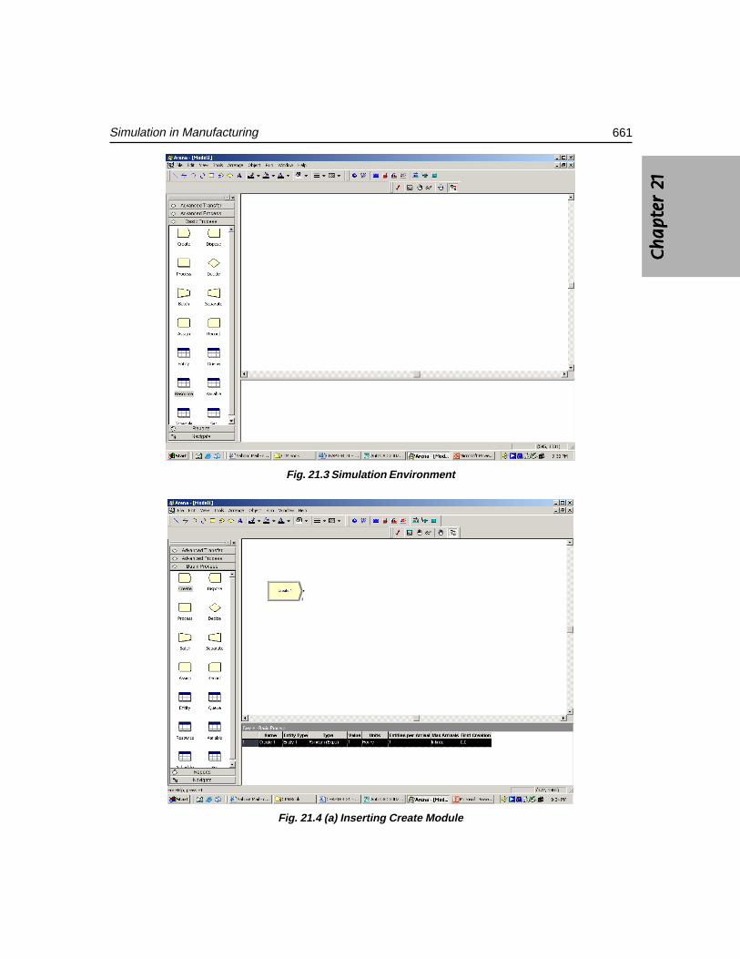
Ch
ap
ter
2C
ha
pte
r 2
Ch
ap
ter
2C
ha
pte
r 2
Ch
ap
ter
2 1111 1
661Simulation in Manufacturing
Fig. 21.3 Simulation Environment
Fig. 21.4 (a) Inserting Create Module
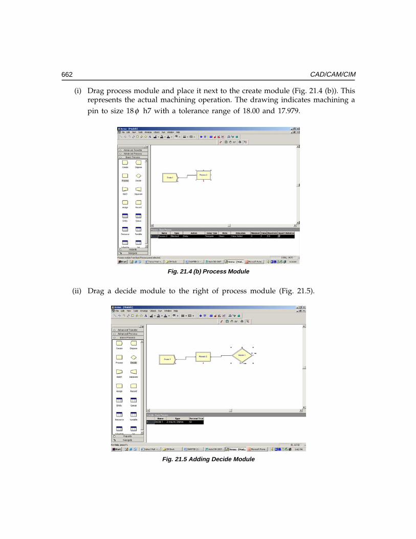
662 CAD/CAM/CIM
(i) Drag process module and place it next to the create module (Fig. 21.4 (b)). Thisrepresents the actual machining operation. The drawing indicates machining apin to size 18φ h7 with a tolerance range of 18.00 and 17.979.
Fig. 21.4 (b) Process Module
(ii) Drag a decide module to the right of process module (Fig. 21.5).
Fig. 21.5 Adding Decide Module
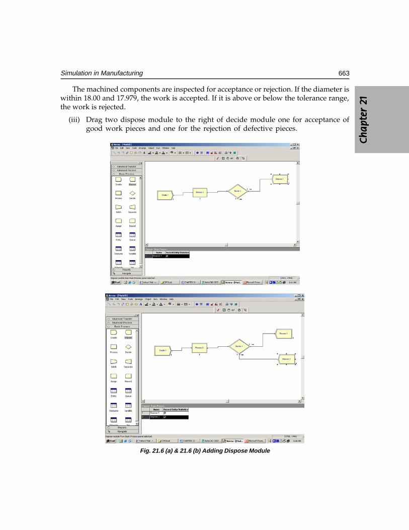
Ch
ap
ter
2C
ha
pte
r 2
Ch
ap
ter
2C
ha
pte
r 2
Ch
ap
ter
2 1111 1
663Simulation in Manufacturing
The machined components are inspected for acceptance or rejection. If the diameter iswithin 18.00 and 17.979, the work is accepted. If it is above or below the tolerance range,the work is rejected.
(iii) Drag two dispose module to the right of decide module one for acceptance ofgood work pieces and one for the rejection of defective pieces.
Fig. 21.6 (a) & 21.6 (b) Adding Dispose Module
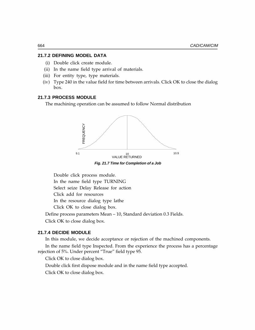
664 CAD/CAM/CIM
21.7.2 DEFINING MODEL DATA
(i) Double click create module.(ii) In the name field type arrival of materials.(iii) For entity type, type materials.(iv) Type 240 in the value field for time between arrivals. Click OK to close the dialog
box.
21.7.3 PROCESS MODULEThe machining operation can be assumed to follow Normal distribution
10 10.99.1
FR
EQ
UE
NC
Y
VALUE RETURNED
Fig. 21.7 Time for Completion of a Job
Double click process module.In the name field type TURNINGSelect seize Delay Release for actionClick add for resourcesIn the resource dialog type latheClick OK to close dialog box.
Define process parameters Mean – 10, Standard deviation 0.3 Fields.
Click OK to close dialog box.
21.7.4 DECIDE MODULEIn this module, we decide acceptance or rejection of the machined components.
In the name field type Inspected. From the experience the process has a percentagerejection of 5%. Under percent “True” field type 95.
Click OK to close dialog box.
Double click first dispose module and in the name field type accepted.
Click OK to close dialog box.
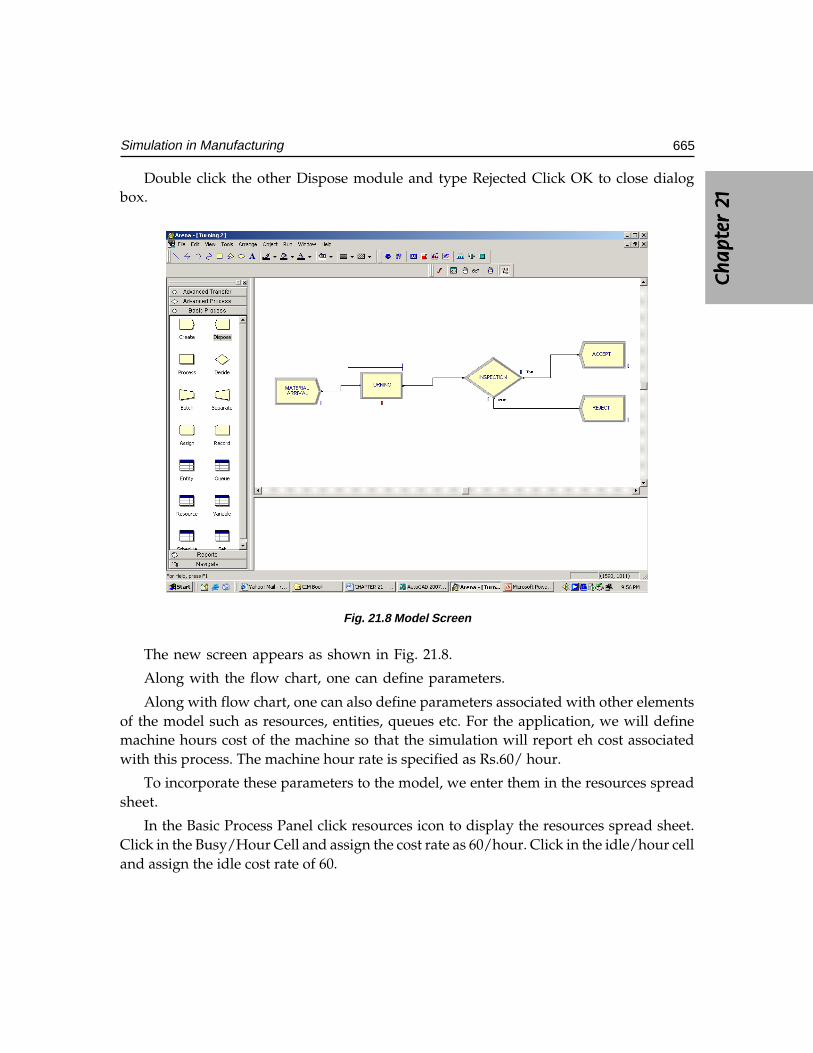
Ch
ap
ter
2C
ha
pte
r 2
Ch
ap
ter
2C
ha
pte
r 2
Ch
ap
ter
2 1111 1
665Simulation in Manufacturing
Double click the other Dispose module and type Rejected Click OK to close dialogbox.
Fig. 21.8 Model Screen
The new screen appears as shown in Fig. 21.8.
Along with the flow chart, one can define parameters.
Along with flow chart, one can also define parameters associated with other elementsof the model such as resources, entities, queues etc. For the application, we will definemachine hours cost of the machine so that the simulation will report eh cost associatedwith this process. The machine hour rate is specified as Rs.60/ hour.
To incorporate these parameters to the model, we enter them in the resources spreadsheet.
In the Basic Process Panel click resources icon to display the resources spread sheet.Click in the Busy/Hour Cell and assign the cost rate as 60/hour. Click in the idle/hour celland assign the idle cost rate of 60.
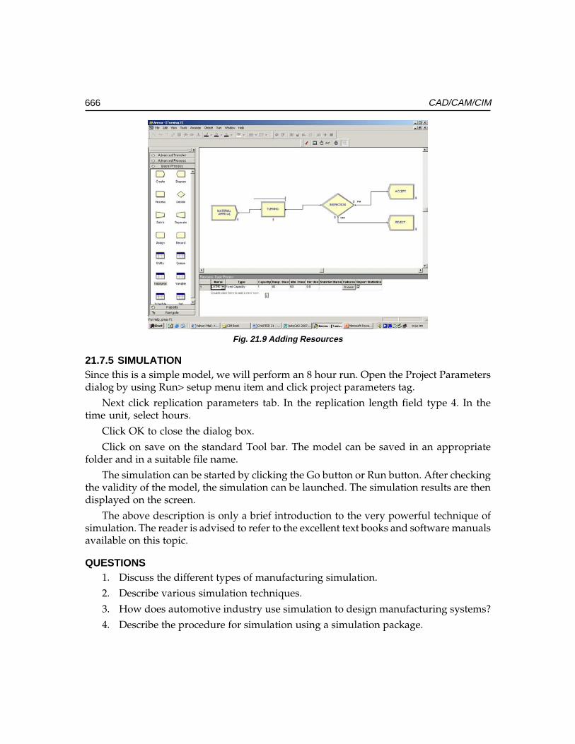
666 CAD/CAM/CIM
Fig. 21.9 Adding Resources
21.7.5 SIMULATIONSince this is a simple model, we will perform an 8 hour run. Open the Project Parametersdialog by using Run> setup menu item and click project parameters tag.
Next click replication parameters tab. In the replication length field type 4. In thetime unit, select hours.
Click OK to close the dialog box.
Click on save on the standard Tool bar. The model can be saved in an appropriatefolder and in a suitable file name.
The simulation can be started by clicking the Go button or Run button. After checkingthe validity of the model, the simulation can be launched. The simulation results are thendisplayed on the screen.
The above description is only a brief introduction to the very powerful technique ofsimulation. The reader is advised to refer to the excellent text books and software manualsavailable on this topic.
QUESTIONS1. Discuss the different types of manufacturing simulation.
2. Describe various simulation techniques.
3. How does automotive industry use simulation to design manufacturing systems?
4. Describe the procedure for simulation using a simulation package.

��
A CIM Model 597Accounts Payable 307Accounts Receivable 308ACIS 583Across the Wall Approach 17Active Edge List 67Analysis 220Anti Aliasing 72APPAS and CADCAM 290Application Layer 536Applications of Industrial Robots 496Arc Net Cards 532Artificial Intelligence 287Assembly Design 169ATM (Asynchronous Transfer Mode)
NETWORKS 554AUTAP 290Automated Storage and Retrieval Systems 624Automatic Guided Vehicles 623Automatic Positioning of Tools 351Automatic Tool Change Systems 614Automating Workflow 560Automation 327Autoplan 290
�
Banded Matrix 213Bar Code Technology 648
Base Band 528Batch Production (Discrete Manufacturing) 4Beam 203Behaviour Modeling 135Benefits of FMS 620Bezier 159Bezier Bicubic Surface Patches 165Bicubic Polynomial Surface 164Bill of Material 304Bill of Materials 150Blocks 143Boundary Representation 127Bresenham’s Algorithm 47Broad Band 528Brushless A.C. Servomotors 359B-SPLINES 161Bus Networks: 530Bus Topology 88Business Plan 296
�
CAD BASED PROCESS PLANNING 270CAD/CAM-CMM Interface 519CAM Technology 451CAM-I CAPP 289Canned Cycles 396Canned Cycles (Fixed Cycles) 377Capacity Requirements Planning 299CAPP based on CAD Models 286CAPP based on Decision Logic 287
�����
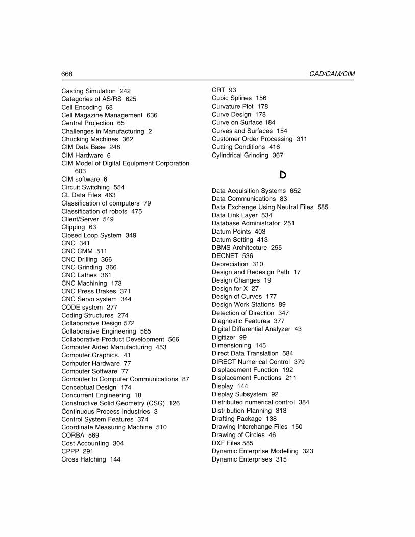
668 CAD/CAM/CIM
Casting Simulation 242Categories of AS/RS 625Cell Encoding 68Cell Magazine Management 636Central Projection 65Challenges in Manufacturing 2Chucking Machines 362CIM Data Base 248CIM Hardware 6CIM Model of Digital Equipment Corporation
603CIM software 6Circuit Switching 554CL Data Files 463Classification of computers 79Classification of robots 475Client/Server 549Clipping 63Closed Loop System 349CNC 341CNC CMM 511CNC Drilling 366CNC Grinding 366CNC Lathes 361CNC Machining 173CNC Press Brakes 371CNC Servo system 344CODE system 277Coding Structures 274Collaborative Design 572Collaborative Engineering 565Collaborative Product Development 566Computer Aided Manufacturing 453Computer Graphics. 41Computer Hardware 77Computer Software 77Computer to Computer Communications 87Conceptual Design 174Concurrent Engineering 18Constructive Solid Geometry (CSG) 126Continuous Process Industries 3Control System Features 374Coordinate Measuring Machine 510CORBA 569Cost Accounting 304CPPP 291Cross Hatching 144
CRT 93Cubic Splines 156Curvature Plot 178Curve Design 178Curve on Surface 184Curves and Surfaces 154Customer Order Processing 311Cutting Conditions 416Cylindrical Grinding 367
�
Data Acquisition Systems 652Data Communications 83Data Exchange Using Neutral Files 585Data Link Layer 534Database Administrator 251Datum Points 403Datum Setting 413DBMS Architecture 255DECNET 536Depreciation 310Design and Redesign Path 17Design Changes 19Design for X 27Design of Curves 177Design Work Stations 89Detection of Direction 347Diagnostic Features 377Digital Differential Analyzer 43Digitizer 99Dimensioning 145Direct Data Translation 584DIRECT Numerical Control 379Displacement Function 192Displacement Functions 211Display 144Display Subsystem 92Distributed numerical control 384Distribution Planning 313Drafting Package 138Drawing Interchange Files 150Drawing of Circles 46DXF Files 585Dynamic Enterprise Modelling 323Dynamic Enterprises 315
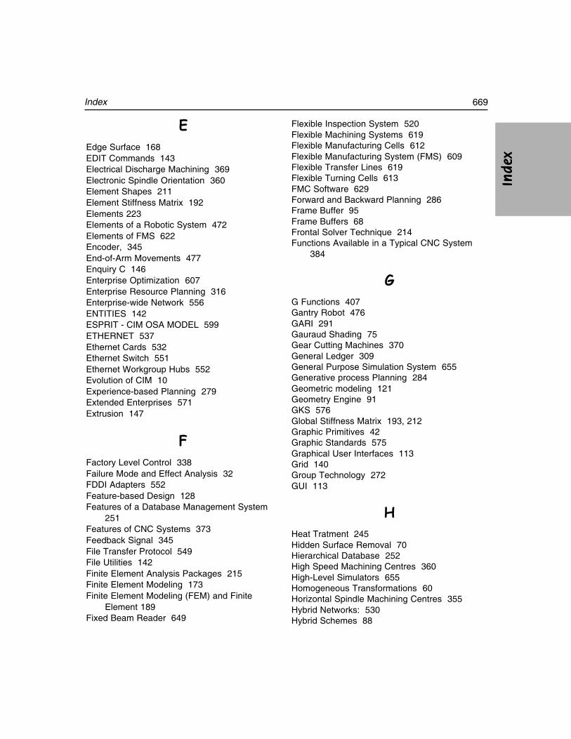
669Index
Ind
exIn
dex
Ind
exIn
dex
Ind
ex
�
Edge Surface 168EDIT Commands 143Electrical Discharge Machining 369Electronic Spindle Orientation 360Element Shapes 211Element Stiffness Matrix 192Elements 223Elements of a Robotic System 472Elements of FMS 622Encoder, 345End-of-Arm Movements 477Enquiry C 146Enterprise Optimization 607Enterprise Resource Planning 316Enterprise-wide Network 556ENTITIES 142ESPRIT - CIM OSA MODEL 599ETHERNET 537Ethernet Cards 532Ethernet Switch 551Ethernet Workgroup Hubs 552Evolution of CIM 10Experience-based Planning 279Extended Enterprises 571Extrusion 147
�
Factory Level Control 338Failure Mode and Effect Analysis 32FDDI Adapters 552Feature-based Design 128Features of a Database Management System
251Features of CNC Systems 373Feedback Signal 345File Transfer Protocol 549File Utilities 142Finite Element Analysis Packages 215Finite Element Modeling 173Finite Element Modeling (FEM) and Finite
Element 189Fixed Beam Reader 649
Flexible Inspection System 520Flexible Machining Systems 619Flexible Manufacturing Cells 612Flexible Manufacturing System (FMS) 609Flexible Transfer Lines 619Flexible Turning Cells 613FMC Software 629Forward and Backward Planning 286Frame Buffer 95Frame Buffers 68Frontal Solver Technique 214Functions Available in a Typical CNC System
384
�
G Functions 407Gantry Robot 476GARI 291Gauraud Shading 75Gear Cutting Machines 370General Ledger 309General Purpose Simulation System 655Generative process Planning 284Geometric modeling 121Geometry Engine 91GKS 576Global Stiffness Matrix 193, 212Graphic Primitives 42Graphic Standards 575Graphical User Interfaces 113Grid 140Group Technology 272GUI 113
Heat Tratment 245Hidden Surface Removal 70Hierarchical Database 252High Speed Machining Centres 360High-Level Simulators 655Homogeneous Transformations 60Horizontal Spindle Machining Centres 355Hybrid Networks: 530Hybrid Schemes 88
670 CAD/CAM/CIM
IBM Concept of CIM 604IGES 587Input Format 286Inspection Machines 373Interactive Graphic Terminals 93INTERNET 548Interpolation 394Intranet 550Inventory Management 302Isometric Projection 66
�
Job Costing 306Job Scheduling 631Joysticks 97
�
Keyboard 82, 97
Labour Performance 313Ladder Logic 334LAN Adapters 551Laser Interferometer 513Laser Telemetric Measuring Systems 513Layers 141Levels of Integration 10, 605Life of a Product 14LINUX 120Local Area Network (LAN) 526
�
Machining Centres 354Main Frame Computer 82Manual Part Programming 404Manufacturing Automation 328Manufacturing Automation Protocol 536Manufacturing Model 457Manufacturing resource planning 293Manufacturing Simulation 195, 653
Mass Production Industries 3Master Production Schedule 297Materials Requirements Planning 298M-Codes 410Mechanism Design 171Mesh Refinement 191MICLASS Classification 277Mini Computers 82MIPLAN 289Miscellaneous Codes 392Modems 87, 531Mother Board 81Mouse 98Moving Beam Reader 649MRP 294MRP-II SOFTWARE 314MS WINDOWS 114MULTICAPP 289Multitasking Machines 364
�
NC POST-PROCESSING 464Network Database 253Network File System (NFS) 543Network Layer 535Network Operating Systems 540Network Techniques 526Network Topologies 530Network Wiring Methods 529Networking 523Non-contact CNC CMM 515Numerical Control 341NURBS 162
�
Objectives of Database 250Off-line (batch) Data Collection Systems 647Oil Hydraulic Systems 329On-line Data Collection 646OpenGL 580Operating Systems 103Opitz Classification System 275Optical Character Recognition 650Order Progress 645Order Release 644Order Scheduling 645
671Index
Ind
exIn
dex
Ind
exIn
dex
Ind
ex
OSI Model 533Outsourcing 37Overview of Pentium PC 80
�
Packet Switching 554Paperless Office 557Parallel Interface 84Parallel Projection 64Parallel/Serial Conversion 85Parametric Design 132Parasolid 581Part Families 272Parts Classification and Coding Systems 272Payroll 310Personal Computers 79Perspective projection 65PHIGS 578Phong Technique 75Physical Layer 534Plane Stress/Plane Strain 205Plastic Injection Molding 245PLC applications 331PLM softwares 36Plotters 101Pneumatic Systems 328Post Process Metrology 516Postprocessor 221Preparatory Codes 392Preparatory Functions 407Preprocessing 217Presentation Layer 536Principal Stresses 206Printers 102Procedure for Simulation 659Process Boundaries. 281Process Boundary Table 281Process Capability 280Process Control: 330Process Family Matrix 282Process Planning 263Process Selection 279Product Data Management 258Product Development Cycle 13Product Development Spiral 16Product Life Cycle Management 35Production Plan 297
Programmable Logic controller 377Programmable Logic Controllers 329Programming Codes 412Programming Features 376, 389Programming of PLC 333Projections 64Public Switched Data Networks 525Purchase Order and Receiving 302
�
Quality Control 505Query Language 255
�
Raster Sca 94Raster Subsystem 92Rasterizing Polygons 69Real time Scan Conversion 67Reflection 73Rendering 69Retrieval of Plans 268Revolution 148Ring Network 88, 530Robot Programming 486Robot Programming Languages 489Robots 471Robust Design 34Rotation 58Router 553RPO 290RS-232 Interface 86Ruled Surface 167Run Length Encoding 68
�
Sales History 312Scaling 140Scaling 57Scan Conversion 66, 91Scan Converting Polygons 69Scan Line Z-Buffer Algo 72SCARA Robot 476Seed Fill Algorithm 70Sequencing: 330

672 CAD/CAM/CIM
Sequential Engineering 16Session Layer 535Shading 75Shearing 59Shop Floor Control 643Shop Floor Data Collection 641Siemens Model of CIM 602Simulation in Automotive Industry 657Simulation Languages 655Simulation Software Packages 656Simultaneous Engineering 18Singularity 179Smart Cards 651Smoothness of surfaces 184Snap 140Solar Cells 346Solid Modeling 125Spar 199Spindle Cooling 359Splines 156Spring Element 197Standard Product Costing 306Standard Product Routing 305Star Network: 530Star Topology 88Statistical Process Control (SPC) 509STEP architecture 591Steps in FEA 217Structural Analysis 193Structured Query Language 256Subroutine Programming 376Super Computers 83Supply Chain Management 320Surface Grinding 366Surface Modeling 124, 152Surface Patch 164Switching: 330System Network Architecture 536
�
Tabulated Surface 167Taguchi Method 34Technical Document Management 558Technical Office Protocol 537
Technology of CAM 454THE NIST - AMRF Hierarchical Model 601Thumb Wheel 100TIPPS 291Token-Ring Adapters 553Tool Nose Radius Compensation 403Tool Offset/Tool Compensation 402Total Quality Management (TQM) 506Touch Screens 97Toyota Production System 32Track Balls 98Transformation 55Translation 58Transmission Media 531Transport Layer 535Turning Centres 361Turret Punch Press 369Turret Slide 363Types of CNC Machines 353Types of Production Systems 612Typical FMS Layout 638
�
Units 140Universal Lathes 362Universal Machining Centres 358Universal Serial Bus 87UNIX 108Unix Kernel 108User Co-ordinate Systems 148
�
Value Engineering 34Value Stream Mapping 32Variant Process Planning 282Vector Spindle Drive 359vertical CNC Lathes 364Vertical Spindle Machining Centres 357View Port 56Virtual Machining 451, 464Virtual Manufacturing 322Virtual Private Network 525Vision System 514
673Index
Ind
exIn
dex
Ind
exIn
dex
Ind
ex
Voice Recognition 651VSAT 556
�
Wave Front 214Welding Simulation 243Wire Frame Modeling 123
Wireless LAN (WLAN) 89Wireless LAN Adapters 552Work Envelope of a Robot 478Workflow Management Systems 561World Wide Web 549
�
Z-Buffer Algorithm 71
���


![Radhakrishnan FINAL REPORT[1]](https://img.pdfslide.us/doc/110x75/577d392f1a28ab3a6b993d7c/radhakrishnan-final-report1.jpg)