Embed Size (px)
Citation preview
1
Functional Analysis Attacks on Logic LockingDeepak Sirone Pramod Subramanyan
Abstract— Logic locking refers to a set of techniques thatcan protect integrated circuits (ICs) from counterfeiting, piracyand malicious functionality changes by an untrusted foundry. Itachieves these goals by introducing new inputs, called key inputs,and additional logic to an IC such that the circuit produces thecorrect output only when the key inputs are set to specific values.The correct values of the key inputs are kept secret from theuntrusted foundry and programmed after manufacturing andbefore distribution, thus rendering piracy, counterfeiting andmalicious design changes infeasible. The security of logic lockingrelies on the assumption that the untrusted foundry cannot inferthe correct values of the key inputs by analysis of the circuit.
In this paper, we introduce a new attack on state-of-the-artlogic locking schemes which invalidates the above assumption. Wepropose Functional Analysis attacks on Logic Locking algorithms(abbreviated as FALL attacks). FALL attacks have two stages.Their first stage is dependent on the locking algorithm andinvolves analyzing structural and functional properties of lockedcircuits to identify a list of potential locking keys. The secondstage is algorithm agnostic and introduces a powerful addition toSAT-based attacks called key confirmation. Key confirmation canidentify the correct key from a list of alternatives and works evenon circuits that are resilient to the SAT attack. In comparisonto past work, the FALL attack is more practical as it can oftensucceed (90% of successful attempts in our experiments) by onlyanalyzing the locked netlist, without requiring oracle access to anunlocked circuit. Our experimental evaluation shows that FALLattacks are able to defeat 65 out of 80 (81%) circuits locked usingStripped-Functionality Logic Locking (SFLL-HD).
I. INTRODUCTION
Globalization and concomitant de-verticalization of thesemiconductor supply chain have resulted in IC design housesbecoming increasingly reliant on potentially untrustworthy off-shore foundries. This reliance has raised concerns of integratedcircuit (IC) piracy, unauthorized overproduction, and maliciousdesign modifications by adversarial entities that may be partof these contract foundries [9, 13, 30]. These issues have bothfinancial [11] and national security implications [21].
A potential solution to these problems is logic locking [3,6, 10, 16, 17]: a set of techniques that introduce additionallogic and new inputs to a digital circuit in order to create a“locked” version of it. The locked circuit operates correctlyif and only if the new inputs, referred to as key inputs, areset to the right values. Typically, key inputs are connectedto a tamper-proof memory and the circuit is activated bythe design house by programming the correct key values inthe tamper-proof memory after manufacturing and prior tosale. The security assumption underlying logic locking is that
Deepak Sirone is currently with the Department of Computer Sciences atUniversity of Wisconsin-Madison. This work was done when he was at theIndian Institute of Technology, Kanpur. E-mail: [email protected].
Pramod Subramanayan is with the Department of Computer Scienceand Engineering at the Indian Institute of Technology, Kanpur. E-mail:[email protected].
the adversary (untrusted foundry) does not know the correctvalues of the key inputs and cannot compute them.
Initial proposals for logic locking did not satisfy this as-sumption and were vulnerable to attack [14, 15, 24, 35, 38].For example, Rajendran et al. [15] used automatic test patterngeneration (ATPG) tools to compute input values that wouldallow an adversary to reveal the values of key bits. Subra-manyan et al. [24] developed the SAT attack which defeated allknown logic encryption techniques at the time. The SAT attackworks by using a Boolean SATisfiability solver to iterativelyfind inputs that distinguish between equivalence classes ofkeys. For each such input, an activated IC (perhaps purchasedfrom the market by the adversary) is queried for the correctoutput and this information is fed back to the SAT solver whencomputing the next distinguishing input. The practicality ofthis attack depends on the number of equivalence classes ofkeys present in the locked circuit.
Much subsequent work has focused on SAT attack resilientlogic locking [31, 32, 36, 39, 40]. These proposals attempt toguarantee that the number of equivalence classes of keys isexponential in the key length. Broadly speaking, they havetwo components. One sub-circuit “flips” the output of theoriginal circuit for a particular cube or set of cubes. Thecube stripping unit is independent of the key inputs but isdependent on the correct key input values. We refer to thiscomponent as the cube stripping unit. This flipped outputis then inverted by a key-dependent circuit that we referto as the progammable functionality restoration unit. Thislatter circuit is guaranteed to have an exponential number ofequivalence classes of keys and ensures SAT attack resilience.Initial proposals along these lines were Anti-SAT [31, 32]and SARLock [36]. However, Anti-SAT was vulnerable tothe signal probability skew (SPS) [36] attack while SARLockwas vulnerable to the Double DIP [20] attack and the Ap-proximate SAT [19] attack. Both schemes are vulnerable toremoval and bypass attacks [33, 37]. Subsequently, Yasin etal. proposed TTLock [40] and Stripped-Functionality LogicLocking (SFLL) [18, 39]. SFLL was the only family of logiclocking techniques resilient to all known attacks at the timeof submission of our conference paper [23].
In this paper, we introduce a novel class of FunctionalAnalysis attacks on Logic Locking (abbreviated as FALLattacks). FALL attacks defeat TTLock and the SFLL-HDh
variant of SFLL. Our approach uses structural and functionalanalyses of circuit nodes to first identify the gates that are theoutput of the cube stripping module in order to determine thelocking key. There are two challenges involved in this.
First, the locked netlist is a sea of gates, and it is unclearwhich of these is the gate being searched for. Examining everygate using computationally expensive functional analyses isnot feasible. Testing whether a gate is equivalent to the cube
arX
iv:1
811.
1208
8v3
[cs
.CR
] 1
0 Ja
n 20
20
2
stripping function for some key value involves solving a quan-tified Boolean formula (QBF). QBF is PSPACE-complete [2]in comparison to to SAT which is “only” NP-complete [8].Therefore, the naıve approach of examining every gate doesnot even scale to small netlists. We tackle these problems bythe development of a set of structural and functional propertiesof the cube stripping function used in SFLL-HDh and useSAT-based analyses to find nodes with these properties. Thesecond challenge is determining the key given the output ofcube stripping unit. Here too, we develop SAT-based analysesto extract potential locking keys from a given circuit node.
In about 90% of successful attempts in our experiments, thefirst stage of the attack shortlists exactly one potential key. Insuch cases, the FALL attack does not require input/output (I/O)oracle access to an unlocked circuit. Any malicious foundrywho can reconstruct gate-level structures from the masks canuse FALL without setting up logic analyzers, loading the scanchain, etc. This suggests that attacking logic locking may bemuch easier than previously believed.
In a few cases, more than one key may be shortlisted.To address this problem, we introduce a novel SAT-basedkey confirmation algorithm. Given a list of suspected keyvalues and I/O oracle access, key confirmation can be usedto find which one (or none) of these suspected key values iscorrect. This has important implications as key confirmationcan be used in isolation with arbitrary analysis techniquesand for arbitrary locking techniques and not just the analysesdeveloped for SFLL-HDh/TTLock in this paper. An attackerneed only guess a key value through some circuit analysis andkey confirmation can be used to verify this guess. For instance,recent work has introduced the SURF attack [5] which usesmachine learning (ML) techniques to guess the key inputvalues. While these techniques can determine a likely key, theycannot guarantee correctness. This is where key confirmationcomes in: it can prove/disprove a high-probability guess. Keyconfirmation succeeds on circuits resilient to the SAT attackand provides a new pathway for the use of powerful Booleanreasoning engines in logic locking attacks.
We present a thorough experimental analysis of the FALLattack. Our evaluation shows that FALL attacks succeed on 65out of 80 benchmark circuits (81%) in our evaluation. Amongthese 65, the functional analysis shortlists exactly one keyfor 58 circuits (90% of successful attempts), supporting ourclaim that Oracle-less attacks are indeed practical. We showexperimentally that the key confirmation attack succeeds onall the circuits we examine and is orders of magnitude fasterthan the SAT attack [24].
A. Contributions
This paper makes the following contributions.• We present functional analysis attacks on logic locking
which use structural and functional analyses to defeatSFLL-HDh and TTLock.
• We present an important improvement to the SAT attackcalled key confirmation that enables the combinationof key value hints gathered from structural/functionalanalyses with the SAT-based analyses. Key confirmation
allows the SAT attack to succeed even against SAT-resilient logic locking and applies to all combinationallogic locking schemes.
• We present a thorough evaluation of FALL attacks andkey confirmation on set of over 80 benchmarks circuitslocked using SFLL-HDh and TTLock. Our attacks defeat65 (81%) of these circuits.
Conference Publication: This paper is based on a con-ference publication in DATE 2019 [23]. This journal paperintroduces the following novel contributions: (i) the key con-firmation attack that extends the SAT attacks to target so called“SAT-resilient” attack schemes (§ VI), and (ii) proofs for theFALL lemmas and the correctness of key confirmation, and(iii) a working example of locking using SFLL and TTLock(§ III-B) and FALL attacks on this example (interspersed withthe text in § IV and § V), and (iv) an experimental evaluationof the key confirmation attack (§ VII-C).
II. BACKGROUND AND NOTATION
This section provides the background and notation used inthe rest of this paper.
A. Notation
Let B = {0, 1} be the Boolean domain. A combinationalcircuit is modeled as a directed acyclic graph (DAG) G =(V,E). Nodes in the graph correspond to logic gates, inputnodes. Some input nodes and logic gates may also be outputs.Edge (v1, v2) ∈ E if v2 is a fanin (input) of the gate v1.
Given a node v ∈ V , define fanins(v) = {v′ | (v, v′) ∈ E}.#fanins(v) is the cardinality of fanins(v). For v ∈ V suchthat #fanins(v) = k, nodefnv is the k-ary Boolean functionassociated with the node; nodefnv : V → (Bk → B). Forexample, if v1 is a 2-input AND gate, nodefnv1 = λab. a∧ b.For input nodes, nodefnv is an uninterpreted 0-ary Booleanfunction (or equivalently, a propositional variable). The circuitfunction of node v, denoted cktfnv is defined recursivelyas: cktfnv = nodefnv(cktfnv1 , . . . , cktfnvn) where vi ∈fanins(v). The transitive fanin cone of a node v, denotedTFC(v), is the set of all nodes vj such that (v, vj) ∈ E or thereexists some vi ∈ V such that (vi, vj) ∈ E and vi ∈ TFC(v).The support of a node, denoted by Supp(v), is the set of allnodes vj such that vj ∈ TFC(v) and #fanins(vj) = 0.
The notation 〈x1, x2, . . . , xm〉 refers to the m-tuple consist-ing of x1, . . . , xm. We will write tuples of variables in uppercase; e.g. X , Y and K. For example X = 〈x1, x2, . . . xm〉.We will use italics: x1, x2, k1, k2, etc. to refer to variables.Constant values are shown in fixed width: X, K, x1, k1, etc.
The notation a∧b refers to the conjunction (AND) of a andb, a ∨ b refers to their disjunction (OR), a ⊕ b refers to theirexclusive or (XOR), and ¬a refers to logical negation (NOT).A literal is either a variable (e.g., a) or its negation (e.g., ¬a).A conjunction of literals (e.g., a ∧ ¬b ∧ c) is called a cube.
B. Representing Circuits and Sets in SAT Solvers
In a locked netlist, some input nodes are key inputs whilethe remaining are circuit inputs. We will represent the tuple
3
of key inputs by K, and the tuple of circuit inputs by X . Theset of outputs of circuit is Y . Define the Boolean functionisKey(v) s.t. isKey(v) = 1 iff node v ∈ K; in other words,isKey(v) is the characteristic function of K.
When using SAT solvers to reason about circuit behavior,we will represent the functional behavior of the circuit via thecharacteristic function of its input/output relation: the Booleanfunction C(X, K, Y) will be satisfiable iff the circuit inputvalues X, and key input values K result in the output valueY. The characteristic function is typically computed using theTseitin transformation [29] which introduces new variables butwe will ignore this detail in the interest of simplicity.
The key confirmation attack needs an I/O oracle for anactivated circuit. This is modelled as a Boolean functionoracle : Bm → Bn where m and n are the number of circuitinputs and outputs respectively. oracle(X) is the output valueof the activated circuit for the input value X.
Similarly, in order to represent sets of Boolean values inSAT solvers, we will use the indicator function of the set.Suppose we have the following set of values for the keyinputs: Kset = {〈1, 0, 1, 1〉, 〈1, 0, 0, 1〉, 〈0, 1, 1, 0〉, 〈0, 0, 1, 0〉}.This set can be represented by the formula ϕ(k1, k2, k3, k4)
.=
(k1 ∧¬k2 ∧ k4)∨ (¬k1 ∧ k3 ∧¬k4). Note that function ϕ hasoutput 1 exactly for the members of the set Kset .
C. Useful Properties of Boolean Functions
We will use the following properties of Boolean functionsin the functional analyses of SFLL and TTLock.Hamming Distance: Given two bit vectors X1 =〈x11, . . . , x1m〉 and X2 = 〈x21, . . . , x2m〉, define HD(X1, X2)
.=∑m
i=1(x1i ⊕ x2i ) to be their Hamming distance.
Unateness: A Boolean function f is said to be positive (resp.negative) unate in the variable x if changing x from 0 to 1while keeping all the other variables the same, never changesthe output of the function f from 1 to 0 (resp. 0 to 1).
Formally, we say that a Boolean function f(x1, . . . , xm) :Bm → B is positive unate in the variable xi iff(x1, . . . , xi−1, 0, xi+1, . . . ) ≤ f(x1, . . . , xi−1, 1, xi+1, . . . ).We say that f is negative unate in the variable xi iff(x1, . . . , xi−1, 1, xi+1, . . . ) ≤ f(x1, . . . , xi−1, 0, xi+1, . . . ).Function f is said to be unate in xi if it is either positiveor negative unate in xi.1 Intuitively, unateness is a mono-tonicity property which states that the function monotonicallyincreases/decreases along with a specific variable x.
In § V, we will show that the cube stripping function ofTTLock has the property of unateness and that this propertycan be exploited to extract the protected cube.
D. A Model of SFLL and TTLock
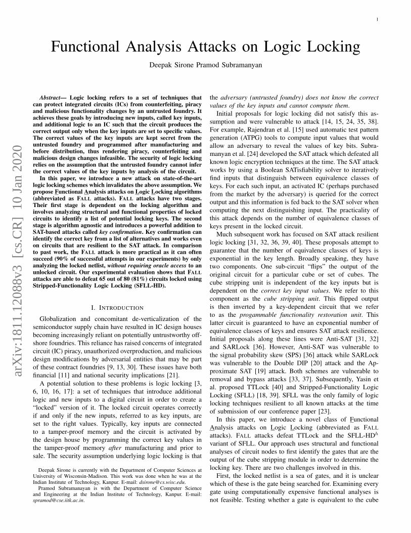
Figure 1 shows the structure of SFLL-HDh and TTLock. Asdescribed in the previous section, the locking scheme consistsof three components. The first is the original circuit which isshown as the blue triangle. The second is the cube stripper,which is shown as the red rectangle. The output of the cubestripper is XOR’d with the output of the original. This means
1a ≤ b is defined as ¬a ∨ b.
Functionality-Stripped Circuit
X = 〈x1, . . . , xm〉
Cube Stripperstrip(Kc)(X)
Functionality
Restoration UnitK = 〈k1, . . . , km〉
Original Circuit
Y
Fig. 1: Overview of SAT attack resilient locking algorithmslike TTLock and SFLL-HDh. We show a single output circuitfor simplicity, additional outputs are handled symmetrically.
that the original circuit produces the “wrong” output for allinputs which result in a high output from the cube stripper.The blue rectangle near the bottom of the figure shows thefunctionality restoration unit.
The circuit inputs are represented by the tuple X =〈x1, . . . , xm〉. The key inputs are represented by the tupleK = 〈k1, . . . , km〉. The output of the cube stripper is theBoolean function striph(Kc)(X). Here Kc is the protected cubeand is a fixed bit-vector value while X is the tuple of inputvariables. We exploit the insight that a general implementationof SFLL must leave structural traces of the value of Kc inthe netlist and our analyses provide algorithms to infer thisvalue for TTLock and SFLL-HDh. We note that there areother variants of SFLL, e.g. SFLL-fault [18]. Extending theanalyses to these variants is not in the scope of this paper.
III. ATTACK OVERVIEW
This section first describes the adversary model for the FALLattack. It then provides an overview of the attack itself.
A. Adversary Model
The adversary is assumed to be a malicious foundry withlayout and mask information. The gate level netlist can bereverse engineered from this [28]. The adversary knows thelocking algorithm and its parameters (e.g., h in SFLL-HDh).We follow [15, 24, 39] etc. and assume the adversary candistinguish between key inputs and circuit inputs, and restrictour attention to combinational circuits. Sequential circuitscan viewed as combinational by treating flip-flop inputs andoutputs as combinational outputs and inputs respectively. Weassume the adversary may have access to an activated circuitthrough which they can observe the output for a specific input.
If parameter h in SFLL-HDh is not known, then one cansweep values of h. This may lead to some incorrect keyvalues being inferred for the wrong values of h, but thesecan be eliminated by the key confirmation attack (see § VI).Distinguishing key inputs from circuit inputs is easily done byexamining which inputs are connected to I/O pads/flip-flopsand which are connected to tamper-proof memory.
4
B. Overview of TTLock and SFLL
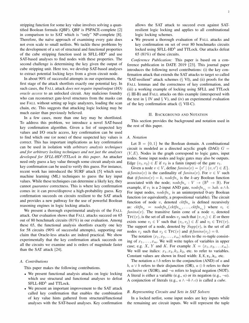
Figure 2a shows a simple circuit that computes the Booleanfunction y = (a ∧ b) ∨ (b ∧ c) ∨ (c ∧ a) ∨ d. This circuitis locked using the TTLock algorithm [40] and the resultingcircuit is shown in Figure 2b. The same circuit locked usingthe SFLL-HDh algorithm is shown in Figure 2c. This sectionprovides an overview of the locking algorithms, the challengesin attacking them and the vulnerabilities in the algorithm thatare exploited by FALL attacks.
1) Overview of TTLock: The locked circuit shown in Fig-ure 2b has two components: (i) a functionality-stripped circuitshown in the dashed blue box, and (ii) the functionalityrestoration unit shown in the dashed cyan box.
Let us first consider the functionality-stripped circuit. Thetwo new additions to the circuit in comparison to Figure 2aare the two gates shown in red. What is the impact of thegate labelled F ? The output of this gate is high only whena ∧ ¬b ∧ ¬c ∧ d = 1, or equivalently when a = d = 1 andb = c = 0. In the SFLL/TTLock terminology, the productterm a ∧ ¬b ∧ ¬c ∧ d is called a protected cube. Notice thefunctionality-stripped circuit’s output differs from the originalcircuit (in Figure 2a) for exactly this cube.
Now let us turn our attention to the functionality restorationunit. This circuit compares the values of inputs a, b, c and dwith the key inputs k1, k2, k3 and k4 respectively. If a = k1,b = k2, c = k3 and d = k4, then the functionality restorationunit flips the output of the functionality-stripped circuit. Whatis the purpose of the functionality restoration unit? If thekey inputs k1, k2, k3 and k4 are set to the same value as theprotected cube, that is if k1 = k4 = 1 and k2 = k3 = 0, thenoutput y of the locked circuit in Figure 2b is identical to theoutput of the original circuit in Figure 2a. In other words, thecircuit only produces the correct output when the keys are setto the protected cube.
2) Overview of SFLL-HDh: Notice that Figure 2c is verysimilar to Figure 2b except for the nodes F and G. Node Fimplements the following function.
F (a, b, c, d).= (¬a ∧ ¬b ∧ ¬c ∧ d) ∨ (a ∧ b ∧ ¬c ∧ d) ∨
(a ∧ ¬b ∧ c ∧ d) ∨ (a ∧ ¬b ∧ ¬c ∧ ¬d) (1)
The output of the function F (a, b, c, d) is 1 for all cubes thatHamming distance 1 from the protected cube a∧¬b∧¬c∧ d.This value 1 corresponds to the parameter h in SFLL-HDh
and is the crucial difference between SFLL-HD and TTLock.In TTLock, the functionality-stripped circuit’s output differsfrom the original circuit for exactly one cube. In contrast, thefunctionality-stripped circuits output differs from the protectedcube for all inputs that are Hamming distance h from theprotected cube in SFLL-HDh. As a result, SFLL-HDh cancause exponentially more output corruption than TTLock.
The functionality restoration unit in SFLL-HDh is analo-gously changed. Node G implements the following function.
G(p, q, r, s).= ¬
((p ∨ q ∨ r) ∧ (p ∨ r ∨ s) ∧(p ∨ q ∨ s) ∧ (q ∨ r ∨ s)
)(2)
a
b
c
d
y
(a) Original circuit.
F
c1
c2
c3
c4
G
a
b
c
d
k1
k2
k3
k4
y
Functionality-Stripped Circuit
FunctionalityRestoration Unit
(b) Circuit locked using TTLock. The protected cube is a ∧¬b ∧ ¬c ∧ d.
F
c1
c2
c3
c4
G
a
b
c
d
k1
k2
k3
k4
sq
pqrs
rp
y
Functionality-Stripped Circuit
FunctionalityRestoration Unit
(c) Circuit locked using SFLL-HD1. All cubes exactly Ham-ming distance 1 from the protected cube a ∧ ¬b ∧ ¬c ∧ d areflipped by the functionality-stripped circuit.
Fig. 2: Example circuit locked with TTLock and SFLL-HD1.
It flips the output of the functionality-stripped circuit for allcubes that are Hamming distance 1 from the values of thekey inputs. If the key inputs are equal to the protected cube,then the original functionality of the circuit is restored because
5
the functionality restoration unit “un-does” the corruptionintroduced by the functionality-stripped circuit.
y
39
37 38
36
24 34 35
23
21
30
3322
18
29
d
12 1528
27
32
10 11 13 14 16 17 19 2025 2631
cak1 b k2 k3 k4
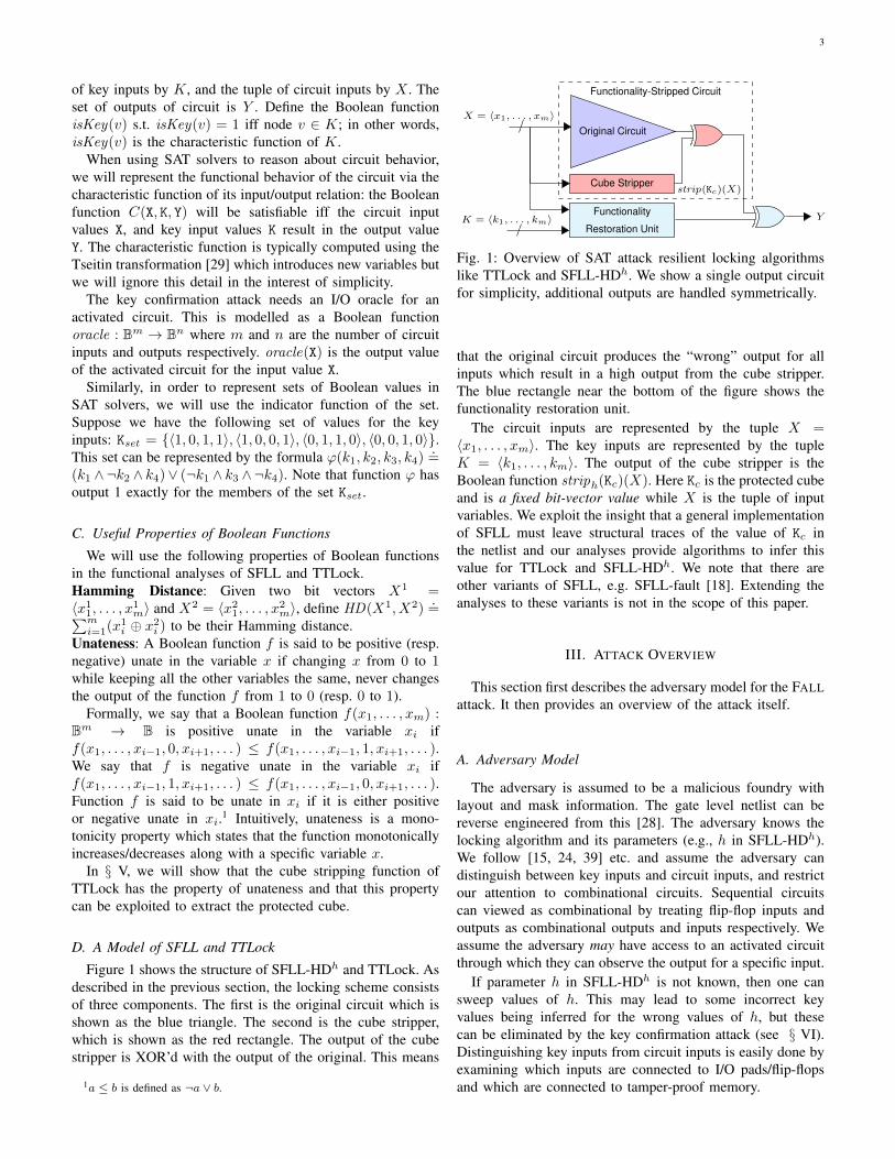
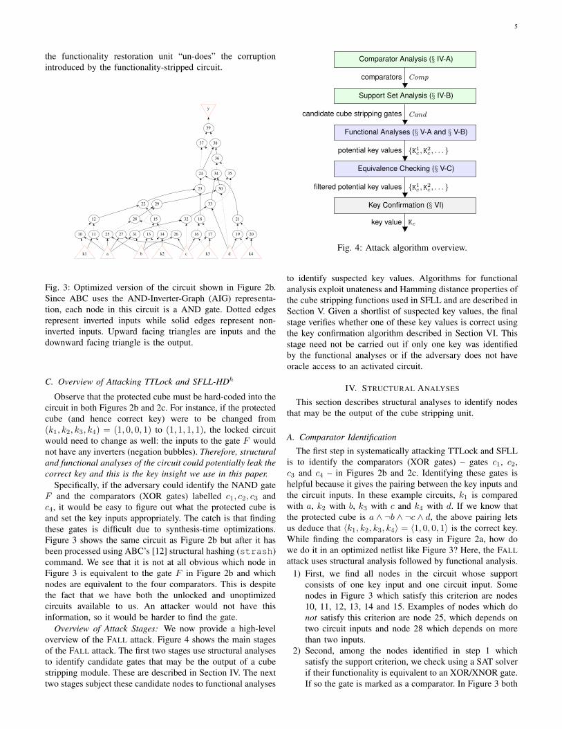
Fig. 3: Optimized version of the circuit shown in Figure 2b.Since ABC uses the AND-Inverter-Graph (AIG) representa-tion, each node in this circuit is a AND gate. Dotted edgesrepresent inverted inputs while solid edges represent non-inverted inputs. Upward facing triangles are inputs and thedownward facing triangle is the output.
C. Overview of Attacking TTLock and SFLL-HDh
Observe that the protected cube must be hard-coded into thecircuit in both Figures 2b and 2c. For instance, if the protectedcube (and hence correct key) were to be changed from(k1, k2, k3, k4) = (1, 0, 0, 1) to (1, 1, 1, 1), the locked circuitwould need to change as well: the inputs to the gate F wouldnot have any inverters (negation bubbles). Therefore, structuraland functional analyses of the circuit could potentially leak thecorrect key and this is the key insight we use in this paper.
Specifically, if the adversary could identify the NAND gateF and the comparators (XOR gates) labelled c1, c2, c3 andc4, it would be easy to figure out what the protected cube isand set the key inputs appropriately. The catch is that findingthese gates is difficult due to synthesis-time optimizations.Figure 3 shows the same circuit as Figure 2b but after it hasbeen processed using ABC’s [12] structural hashing (strash)command. We see that it is not at all obvious which node inFigure 3 is equivalent to the gate F in Figure 2b and whichnodes are equivalent to the four comparators. This is despitethe fact that we have both the unlocked and unoptimizedcircuits available to us. An attacker would not have thisinformation, so it would be harder to find the gate.
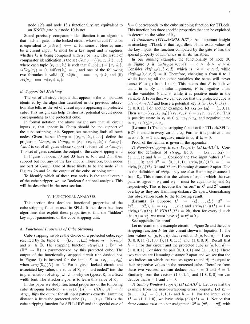
Overview of Attack Stages: We now provide a high-leveloverview of the FALL attack. Figure 4 shows the main stagesof the FALL attack. The first two stages use structural analysesto identify candidate gates that may be the output of a cubestripping module. These are described in Section IV. The nexttwo stages subject these candidate nodes to functional analyses
Comparator Analysis (§ IV-A)
Support Set Analysis (§ IV-B)
Functional Analyses (§ V-A and § V-B)
Equivalence Checking (§ V-C)
Key Confirmation (§ VI)
comparators Comp
candidate cube stripping gates Cand
potential key values {K1c , K2c , . . . }
filtered potential key values {K1c , K2c , . . . }
key value Kc
Fig. 4: Attack algorithm overview.
to identify suspected key values. Algorithms for functionalanalysis exploit unateness and Hamming distance properties ofthe cube stripping functions used in SFLL and are described inSection V. Given a shortlist of suspected key values, the finalstage verifies whether one of these key values is correct usingthe key confirmation algorithm described in Section VI. Thisstage need not be carried out if only one key was identifiedby the functional analyses or if the adversary does not haveoracle access to an activated circuit.
IV. STRUCTURAL ANALYSES
This section describes structural analyses to identify nodesthat may be the output of the cube stripping unit.
A. Comparator Identification
The first step in systematically attacking TTLock and SFLLis to identify the comparators (XOR gates) – gates c1, c2,c3 and c4 – in Figures 2b and 2c. Identifying these gates ishelpful because it gives the pairing between the key inputs andthe circuit inputs. In these example circuits, k1 is comparedwith a, k2 with b, k3 with c and k4 with d. If we know thatthe protected cube is a ∧ ¬b ∧ ¬c ∧ d, the above pairing letsus deduce that 〈k1, k2, k3, k4〉 = 〈1, 0, 0, 1〉 is the correct key.While finding the comparators is easy in Figure 2a, how dowe do it in an optimized netlist like Figure 3? Here, the FALLattack uses structural analysis followed by functional analysis.
1) First, we find all nodes in the circuit whose supportconsists of one key input and one circuit input. Somenodes in Figure 3 which satisfy this criterion are nodes10, 11, 12, 13, 14 and 15. Examples of nodes which donot satisfy this criterion are node 25, which depends ontwo circuit inputs and node 28 which depends on morethan two inputs.
2) Second, among the nodes identified in step 1 whichsatisfy the support criterion, we check using a SAT solverif their functionality is equivalent to an XOR/XNOR gate.If so the gate is marked as a comparator. In Figure 3 both
6
node 12’s and node 13’s functionality are equivalent toan XNOR gate but node 10 is not.
Stated precisely, comparator identification is an algorithmthat finds all gates in the locked circuit whose circuit functionis equivalent to (z ⊕ xi) ⇐⇒ ki for some z. Here xi mustbe a circuit input, ki must be a key input and z captureswhether ki is being compared with xi or ¬xi. The result ofcomparator identification is the set Comp = {〈vi, xi, ki〉, . . . }where each tuple 〈vi, xi, ki〉 is such that Supp(vi) = {xi, ki},isKey(xi) = 0, isKey(ki) = 1, and one of the followingtwo formulas is valid: (i) cktfnvi ⇐⇒ xi ⊕ ki and (ii)cktfnvi ⇐⇒ ¬(xi ⊕ ki).
B. Support Set Matching
The set of all circuit inputs that appear in the comparatorsidentified by the algorithm described in the previous subsec-tion also tells us the set of circuit inputs appearing in protectedcube. This insight can help us shortlist potential circuit nodescorresponding to the protected cube.
In formal notation, the above insight says that all circuitinputs xi that appear in Comp should be the support ofthe cube stripping unit. Support set matching finds all suchnodes. Given the set Comp = {〈vi, xi, ki, 〉, . . . }, define theprojection Compx as Compx = {xi | (vi, xi, ki) ∈ Comp}.Cand is set of all gates whose support is identical to Compx.This set of gates contains the output of the cube stripping unit.
In Figure 3, nodes 30 and 33 have a, b, c and d in theirsupport but not any of the key inputs. Therefore, both nodesare part of Comp. One of these likely to be the node F inFigures 2b and 2c, the output of the cube stripping unit.
To identify which of these two nodes is the actual outputof the cube stripper, we use Boolean functional analysis. Thiswill be described in the next section.
V. FUNCTIONAL ANALYSES
This section first develops functional properties of thecube stripping function used in SFLL. It then describes threealgorithms that exploit these properties to find the “hidden”key input parameters of the cube stripping unit.
A. Functional Properties of Cube Stripping
Cube stripping involves the choice of a protected cube, rep-resented by the tuple Kc = 〈k1, . . . , km〉 where m = |Comp|and ki ∈ B. The stripping function strip(Kc) : Bm →(Bm → B) is parameterized by this protected cube. Theoutput of the functionality stripped circuit (the dashed boxin Figure 1) is inverted for the input X = 〈x1, . . . , xm〉when strip(Kc)(X) = 1. For a given locked circuit andassociated key value, the value of Kc is “hard-coded” into theimplementation of strip, which is why we typeset Kc in a fixedwidth font. The attacker’s goal is to learn this value of Kc.
In this paper we study functional properties of the followingcube stripping function: striph(Kc)(X)
.= HD(Kc, X) = h.
striph flips the output for all input patterns exactly Hammingdistance h from the protected cube 〈k1, . . . , km〉. This is thecube stripping function for SFLL-HDh and the special case of
h = 0 corresponds to the cube stripping function for TTLock.This function has three specific properties that can be exploitedto determine the value of Kc.
1) Unateness (TTLock/SFLL-HD0): An important insightin attacking TTLock is that regardless of the exact values ofthe key inputs, the function computed by the gate F has thespecial property of unateness in all its variables.
In our running example, the functionality of node 30in Figure 3 is cktfn30(a, b, c, d) = a ∧ ¬b ∧ ¬c ∧ d.Consider cktfn30(1, b, c, d), which is ¬b ∧ ¬c ∧ d, whilecktfn30(0, b, c, d) = 0. Therefore, changing a from 0 to 1while keeping all the other variables the same will nevercause F to go from 1 to 0. This means that F is positiveunate in a. By a similar argument, F is negative unatein the variables b and c, while it is positive unate in thevariable d. From this, we can deduce that the protected cube isa∧¬b∧¬c∧d and hence a potential key is (k1, k2, k3, k4) =(1, 0, 0, 1). For another example, let 〈k1, k2, k3〉 = 〈1, 0, 1〉.Then strip0(〈k1, k2, k3〉)(〈x1, x2, x3〉) = x1 ∧¬x2 ∧ x3. Thisis positive unate in x1 as 0 ≤ ¬x2 ∧ x3, and negative unatein x2 as 0 ≤ x1 ∧ x3.
(Lemma 1) The cube stripping function for TTLock/SFLL-HD0 is unate in every variable xi. Further, it is positive unatein xi if ki = 1 and negative unate in xi if ki = 0.
Proof of the lemma is given in the appendix.2) Non-Overlapping Errors Property (SFLL-HDh): Con-
sider the definition of striph, let Kc = 〈k1, . . . , k4〉 =〈1, 1, 1, 1〉 and h = 1. Consider the two input values X1 =〈1, 1, 1, 0〉 and X2 = 〈0, 1, 1, 1〉. strip1(Kc)(X
1) = 1 =strip1(Kc)(X
2). X1 and X2 are Hamming distance 2 apart. Dueto the definition of strip1 they are also Hamming distance 1from Kc. This means that the values of xi on which the twopatterns agree – x2 and x3 – must be equal to k2 and k3respectively. This is because the “errors” in X1 and X2 cannotoverlap as they are Hamming distance 2h apart. Generalizingthis observation leads to the following result.
(Lemma 2) Suppose X1 = 〈x11, . . . , x1m〉, X2 =〈x21, . . . , x2m〉, Kc = 〈k1, . . . , km〉 and striph(Kc)(X
1) = 1 =striph(Kc)(X
2). If HD(X1, X2) = 2h, then for every j suchthat x1j = x2j , we must have x1j = x2j = kj .
See appendix for proof.Let us return to the example circuit in Figure 2c and the cube
stripping function F for this circuit shown in Equation 1. Thefour values of (a, b, c, d) that result in F (a, b, c, d) = 1 are(0, 0, 0, 1), (1, 1, 0, 1), (1, 0, 1, 1) and (1, 0, 0, 0). Recall thath = 1 for this circuit and the protected cube is (a, b, c, d) =(1, 0, 0, 1). Consider the pair (0, 0, 0, 1) and (1, 1, 0, 1). Thesetwo vectors are Hamming distance 2 apart and we see that thetwo indices on which the vectors agree (c and d) are equal totheir respective values in the protected cube. Therefore fromthese two vectors, we can deduce that c = 0 and d = 1.Similarly from the vectors (1, 0, 1, 1) and (1, 0, 0, 0) we candeduce that a = 1 and b = 0.
3) Sliding Window Property (SFLL-HDh): Let us revisit theexample from the non-overlapping errors property. Let Kc =〈k1, . . . , k4〉 = 〈1, 1, 1, 1〉 and h = 1. For the input valueX1 = 〈1, 1, 1, 0〉, we have strip1(Kc)(X
1) = 1. Notice thatthere cannot exist another assignment X2 = 〈x21, . . . , x24〉 with
7
x24 = 0, HD(X1, X2) = 2 and strip1(Kc)(X2) = 1. This is
because x24 6= k4, so the remaining bits in X2 must be equal toKc so that strip1(Kc)(X
2) = 1. But this forces the Hammingdistance between X1 and X2 to be 0 (and not 2 as desired).This observation leads to the following result.
(Lemma 3) Consider the assignments X1 = 〈x11, . . . , x1m〉and X2 = 〈x21, . . . , x2m〉. Let Kc = 〈k1, . . . , km〉 as before.The formula striph(Kc)(X
1) = 1 ∧ striph(Kc)(X2) = 1 ∧
HD(X1, X2) = 2h∧ x1j = x2j ∧ x1j = b is satisfiable iff b = kj .The proof of this lemma is given in the appendix.
B. Functional Analysis Algorithms
Algorithm 1 Algorithm ANALYZEUNATENESS
1: procedure ANALYZEUNATENESS(c)2: keys← ∅3: for xi ∈ Supp(c) do4: if isPositiveUnate(c, xi) then5: keys← keys ∪ (xi 7→ 1)6: else if isNegativeUnate(c, xi) then7: keys← keys ∪ (xi 7→ 0)8: else return ⊥9: end if
10: end for11: return keys12: end procedure
In this subsection, we describe three attack algorithms onSFLL that are based on Lemmas 1, 2 and 3. Each algorithmtakes as input a candidate node c in the circuit DAG. Let X =Supp(c). The functional analyses described in this subsectiondetermine whether the circuit function of this node cktfnc(X)is equivalent to strip(Kc)(X) for some assignment to Kc. Inother words, we are trying to solve the quantified Boolean for-mula (QBF): ∃Kc. ∀X. cktfnc(X) = strip(Kc)(X). However,solving this QBF instance is computationally hard. So insteadwe exploit Lemmas 1, 2 and 3 to determine potential valuesof Kc and verify this “guess” using combinational equivalencechecking.
1) ANALYZEUNATENESS: This is shown in Algorithm 1and can be used to attack SFLL-HD0/TTLock. It takes as inputa circuit node c and outputs an assignment to each node inthe support set of c if the function represented by c is unate,otherwise it returns ⊥. This assignment is the protected cube.Applicability: This algorithm is only applicable to SFLL-HDh
when h = 0, i.e. TTLock.2) SLIDINGWINDOW: Algorithm 2 takes as input the cir-
cuit node c and the algorithm checks if c behaves as thecube stripping unit of SFLL-HDh. It works by asking if thereare two distinct satisfying assignments to cktfnc which areHamming distance of 2h apart. If no such assignment existsthen ⊥ is returned. Otherwise, by Lemma 2, bits which areequal in both satisfying assignments must also be equal tothe corresponding key bits. The remaining bits are obtainedby iterating through each remaining bit and applying the SATquery in Lemma 3. If any query is inconsistent with Lemma 3
Algorithm 2 Algorithm SLIDINGWINDOW
1: procedure SLIDINGWINDOW(c)2: keys← ∅3: S ← Supp(c)4: c′ ← subsitute(c, {(xi, x′i) | x ∈ S})5: F ← c ∧ c′ ∧HD(Supp(c),Supp(c′)) = 2h6: if solve(F ) = UNSAT then return ⊥7: end if8: for xi ∈ S do9: (mi, m
′i)← (modelxi(F ), modelx′
i(F ))
10: if mi = m′i then11: keys← keys ∪ (xi 7→ mi)12: else13: ri ← solve(F ∧ (xi = x′i ∧ x′i = mi))14: r′i ← solve(F ∧ (xi = x′i ∧ x′i = m′i))15: if ri = SAT ∧ r′i = UNSAT then16: keys← keys ∪ (xi 7→ mi)17: else if ri = UNSAT ∧ r′i = SAT then18: keys← keys ∪ (xi 7→ m′i)19: else20: return ⊥21: end if22: end if23: end for24: return keys25: end procedure
during this process then ⊥ is returned. If successful, the returnvalue is the protected cube.Applicability: This algorithm is used to attack SFLL-HDh for0 < h < bm/2c where m is the number of key inputs. Notethat h > bm/2c is symmetric to h < bm/2c with respect tonegation of the key.
3) DISTANCE2H: Algorithm 3 is based on Lemma 2. Thisprocedure is similar to SLIDINGWINDOW in that it computestwo satisfying assignments to c that are distance of 2h apart.Any bits that are equal between the two assignments must beequal to the key bits. The remaining bits are computed byasking if there are two more satisfying assignments such thatthe bits which were not equal in the first pair of assignmentsare now equal. These new assignments must also be Ham-ming distance of 2h apart. The second query, if successful,determines the remaining key bits by Lemma 3.Applicability: This algorithm is applicable when 0 < 4h ≤ mwhere m is the number of key inputs.
C. Equivalence Checking
It is important to note that Lemmas 1, 2 and 3 encode neces-sary but not sufficient properties of the cube stripping function.We ensure sufficiency by using combinational equivalencechecking. Suppose the key value returned by Algorithm 1, 2 or3 is Kc. We check satisfiability of striph(Kc)(X) 6= cktfnc(X)where X is the support of the node c. If this query isunsatisfiable, this means that the node c is equivalent to cubestripping function striph(Kc).
8
Algorithm 3 Algorithm DISTANCE2H
1: procedure DISTANCE2H(c)2: S ← Supp(c)3: c′ ← subsitute(c, {(xi, x′i) | x ∈ S})4: F ← c ∧ c′ ∧HD(Supp(c),Supp(c′)) = 2h5: if solve(F ) = UNSAT then return ⊥6: end if7: MF ← {(xi, modelxi
(F ), modelx′i(F )) | xi ∈ S}
8: keysA ← {(xi 7→ mi) | (xi, mi, m′i) ∈MF ∧ mi = m′i}9: Cnst ← {(xi = x′i) | (xi, mi, m′i) ∈MF ∧ mi 6= m′i}
10: G← F ∧ (∧
pi∈Cnst pi)11: if solve(G) = UNSAT then return ⊥12: end if13: MG ← {(xi, modelxi
(G), modelx′i(G)) | xi ∈ S}
14: keysB ← {(xi 7→ mi) | (xi, mi, m′i) ∈MG ∧ mi = m′i}15: return keysA ∪ keysB16: end procedure
VI. KEY CONFIRMATION
In most cases the functional analyses determine exactlyone correct locking key. However, there are few exceptions.One case occurs when both the output of the cube strippermodule (F in Figure 2c) as well as its negation (¬F ) appearin the circuit. In this case, the algorithms may shortlist boththe correct key, e.g. 〈1, 0, 0, 1〉 and its complement 〈0, 1, 1, 0〉Another scenario is when purely by coincidence the circuitcontains a function that happens to look like the cube strippermodule, but is actually not. In the case of TTLock, the lattercase occurs when the circuit contains any unate function of allthe circuit inputs. In this case too, the algorithms will outputmultiple keys: one of these will be correct while the remainingare spurious. How do we determine which of the keys in thislist is the correct key? We introduce the key confirmationalgorithm to solve this problem.
The key confirmation algorithm takes as input a circuitrepresented by its characteristic relation C(X,K, Y ), a setof key values represented by the indicator function of thisset ϕ(K) and an I/O oracle. The indicate function ϕ is aBoolean formula over the key variables that constrains thesearch space of the algorithm. For example, suppose the circuitanalyses have shortlisted two keys 〈1, 1, 0, 1〉 and 〈0, 0, 1, 0〉.The ϕ(K)
.= (k1 ∧ k2 ∧¬k3 ∧ k4)∨ (¬k1 ∧¬k2 ∧ k3 ∧¬k4).
The algorithm either returns a key value Kc s.t. Kc |= ϕ or ⊥if no key value is consistent with ϕ and the oracle.
If no information about the keys is available then we setϕ(K) = true; this corresponds to the universal set and in thiscase, the algorithm devolves into the standard SAT attack [24].
A. Algorithm Description
To understand the algorithm, it is helpful to review thenotion of a distinguishing input introduced by Subramanyanet al. [24] in the SAT attack paper. Following the notation inthat paper, we will represent the circuit by its characteristicrelation C(X,K, Y ), where X is the vector of circuit inputs,K is the vector of key inputs and Y is the vector of circuitoutputs. Recall that the relation C(X, K, Y) is satisfiable iff the
circuit produces output Y for input X when the key inputsare set to K. Given the above relation, we say that Xd is adistinguishing input pattern for the key inputs K1 and K2 iffC(Xd, K1, Y
d1)∧C(Xd, K2, Yd2)∧(Yd1 6= Yd2) is satisfiable. In other
words, a distinguishing input pattern for two keys is an inputsuch that the circuit produces different outputs for this inputand the corresponding keys.
Algorithm 4 Key Confirmation Algorithm
1: procedure KEYCONFIRMATION(C,ϕ, oracle)2: i← 13: P1 ← ϕ(K1)4: Q1 ← C(X,K1, Y1) ∧ C(X,K2, Y2) ∧ Y1 6= Y25: while true do6: if solve[Pi] = UNSAT then7: return ⊥8: end if9: Ki ← modelK1
(Pi)10: if solve[Qi ∧ (K1 = Ki)] = UNSAT then11: return Ki12: end if13: Xdi ← modelX(Qi)14: Ydi ← oracle(Xdi )15: Pi+1 ← Pi ∧ C(Xdi ,K1, Y
di )
16: Qi+1 ← Qi ∧ C(Xdi ,K2, Ydi )
17: i← i+ 118: end while19: end procedure
The SAT-based key confirmation is shown in Algorithm 4.The two main components of the algorithm are the sequencesof formulas Pi and Qi, which we implemented using two SATsolver objects. Pi are used to produce candidate key valuesthat are consistent with ϕ and the I/O patterns observed thusfar. Note that since P1 is ϕ, all subsequent Pi =⇒ ϕ. Qi
is used to generate distinguishing inputs. When Pi becomesUNSAT, it means no key value is consistent with ϕ and theoracle. Or equivalently, the initial “guess” encoded in ϕ wasincorrect. The algorithm terminates with a correct key whenQi becomes UNSAT, i.e. no more distinguishing inputs exist.
The algorithm works as follows. In line 9, we extract the keyvalue Ki that is consistent with ϕ and the input/output patternsseen thus far. In line 10, we pose a query to the SAT solver tofind a distinguishing input such that K1 = Ki. In line 13, weextract this distinguishing input. The oracle is queried for theoutput for this input in line 14. Finally, the formulas Pi andQi are updated with the newly obtained input/output patternin lines 15 and 16. The two significant differences from theSAT attack [24] are: (i) the two solver objects correspondingto Pi and Qi which helps separate the generation of candidatekeys from the generation of distinguishing inputs, and (ii)the restriction that Pi =⇒ ϕ. The former allows us todifferentiate between two different types of UNSAT results fromthe solver: no key value being consistent with ϕ (line 7),and no more distinguishing inputs (line 10). This would notbe possible in the SAT attack formulation because we onlyget one type of UNSAT result. The latter change ensures that
9
instead of searching over the entire space of keys, we restrictthe search to keys satisfying ϕ.
B. Examples of Key Confirmation Algorithm Execution
Consider the operation of the key confirmation algorithmfor the TTLock netlist shown in Figure 2b. Without anyinformation about possible key values, i.e. when ϕ = true,then every input is a distinguishing input for this circuit andevery input rules out only one incorrect key value. This ensuressecurity against the plain SAT attack.
Now consider the case when ϕ(k1, k2, k3, k4) = k1∧¬k2∧¬k3 ∧ k4; this corresponds to the key value 〈k1, k2, k3, k4〉 =〈1, 0, 0, 1〉. Lines 6–13 of Algorithm 4 attempt to find an inputthat distinguishes between the key value 〈1, 0, 0, 1〉 and allother key values. Note that every such distinguishing inputmust be part of the protected cube. As a result, the firstdistinguishing input is 〈a, b, c, d〉 = 〈1, 0, 0, 1〉. When theoracle is queried for this input, we find that output is 1. Afterthis constraint is added to the formulas in lines 15 and 16,no more distinguishing inputs can be found. The algorithmterminates on line 11 with 〈1, 0, 0, 1〉 as the correct key.
Let us consider a scenario where we guess the wrong key.Suppose ϕ(k1, k2, k3, k4) = k1 ∧ ¬k2 ∧ ¬k3 ∧ ¬k4; thiscorresponds to the key value 〈k1, k2, k3, k4〉 = 〈1, 0, 0, 0〉. Thefirst distinguishing input between this key and all other keystested by the solver is 〈a, b, c, d〉 = 〈1, 0, 0, 0〉. The correctoutput for this input pattern is 0, and this is returned by theoracle. Note the output of the functionality stripped circuit forthis input 〈1, 0, 0, 0〉 is 0 and then the functionality restorationunit flips this output to 1 because of the initial constraint onthe key inputs. Therefore, when we now add this constraint tothe formula P in line 15, the formula P becomes unsatisfiable.This causes the algorithm to terminate with failure on line 7.
C. Correctness of Key Confirmation
Correctness of Algorithm 4 is stated in the following lemma.(Lemma 4) Algorithm 4 terminates and returns either (i)
the key Kc or (ii) ⊥. The former occurs iff Kc |= ϕ and∀X. C(X, Kc, Y ) ⇐⇒ Y = oracle(X). The latter occurs iffno such Kc exists.
The proof of this lemma is given in the appendix.The second clause of Lemma 4 is important to emphasize.
Key confirmation terminates with the result ⊥ iff no key valueKc s.t. Kc |= ϕ is correct for the given oracle. This implies keyconfirmation can be safely used even if the key value was“incorrectly” guessed – the algorithm will detect this.
VII. EVALUATION
This section describes our experimental evaluation of FALLattacks. We describe the evaluation methodology, then presentthe results of the functional analyses, after which we presentour evaluation of the key confirmation attack.
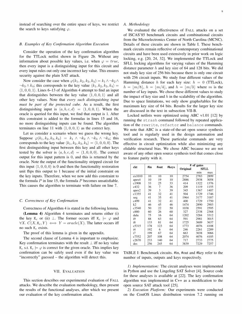
A. MethodologyWe evaluated the effectiveness of FALL attacks on a set
of ISCAS’85 benchmark circuits and combinational circuitsfrom the Microelectronics Center of North Carolina (MCNC).Details of these circuits are shown in Table I. These bench-mark circuits remain reflective of contemporary combinationalcircuits and have been used extensively in prior work on logiclocking, e.g. [20, 24, 32]. We implemented the TTLock andSFLL locking algorithms for varying values of the Hammingdistance parameter h and key size of 64 and 128 bits. We didnot study key size of 256 bits because there is only one circuitwith 256 circuit inputs. We study four different values of theHamming distance h for each key size: h = 0 (TTLock),h = bm/8c, h = bm/4c, and h = bm/3c where m is thenumber of key inputs. We chose these different values to studythe impact of key size and h in the scalability of the algorithm.Due to space limitations, we only show graphs/tables for themaximum key size of 64 bits. Results for the larger key sizeare discussed in the text in subsection VII-B.
Locked netlists were optimized using ABC v1.01 [12] byrunning the strash command followed by repeated applica-tion of the rewrite, refactor and balance commands.We note that ABC is a state-of-the-art open source synthesistool and is regularly used in the design automation andverification research. These particular commands are veryeffective in circuit optimization while also minimizing anyelidable structural bias. We chose ABC because we are notaware of any other open source synthesis tool that comes closeto feature parity with it.
ckt #in #out #keys # of gatesOriginal SFLL
min maxex1010 10 10 10 2754 2783 2899apex4 10 19 10 2886 2938 3058c1908 33 25 33 414 1322 1376c432 36 7 36 209 1119 1155apex2 39 3 39 345 1367 1407c1355 41 32 41 504 1729 1746seq 41 35 41 1964 3177 3187c499 41 32 41 400 1729 1750k2 46 45 46 1474 2890 2903c3540 50 22 50 1038 2591 2595c880 60 26 60 327 2338 2368dalu 75 16 64 1202 3284 3312i9 88 63 64 591 2981 3015i8 133 81 64 1725 3609 3637c5315 178 123 64 1773 4076 4108i4 192 6 64 246 2261 2289i7 199 67 64 663 3038 3066c7552 207 108 64 2074 4076 4105c2670 233 140 64 717 2733 2775des 256 245 64 3839 7229 7257
TABLE I: Benchmark circuits. #in, #out and #key refer to thenumber of inputs, outputs and keys respectively.
1) Implementation: The circuit analyses were implementedin Python and use the Lingeling SAT Solver [4]. Source codefor these analyses is available at [22]. The key confirmationalgorithm was implemented in C++ as a modification to theopen source SAT attack tool [25].
2) Execution Platform: Our experiments were conductedon the CentOS Linux distribution version 7.2 running on
10
0 200 400 600 800 1000Execution Time (s)
0
4
8
12
16
# of
ben
chm
arks
solv
ed
SFLL-HD0
SAT-AttackAnalyzeUnateness
0 200 400 600 800 1000Execution Time (s)
0
4
8
12
16
# of
ben
chm
arks
solv
ed
SFLL-HDh where h = m/8
SAT-AttackSlidingWindowDistance2H
0 200 400 600 800 1000Execution Time (s)
0
4
8
12
16
# of
ben
chm
arks
solv
ed
SFLL-HDh where h = m/4
SAT-AttackSlidingWindowDistance2H
0 200 400 600 800 1000Execution Time (s)
0
4
8
12
16
# of
ben
chm
arks
solv
ed
SFLL-HDh where h = m/3
SAT-AttackSlidingWindow
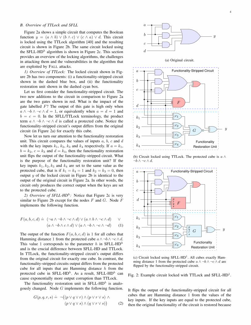
Fig. 5: Circuit analyses: execution time vs number of benchmarks solved in that time.
ex10
10
apex
4
c190
8
c432
apex
2
c135
5
seq
c499 k2
c354
0
c880
dalu i9 i8
c531
5 i4 i7
c755
2
c267
0
des10 1
100
101
102
103
104
Mea
n ex
ecut
ion
time
(s)
Key Verification SAT Attack
Fig. 6: Mean execution times of key confirmation and SAT attacks.
11
28-core Intel R© Xeon R© Platinum 8180 (“SkyLake”) ServerCPUs. All experiments had a time limit of 1000 seconds.
B. Circuit Analysis Results
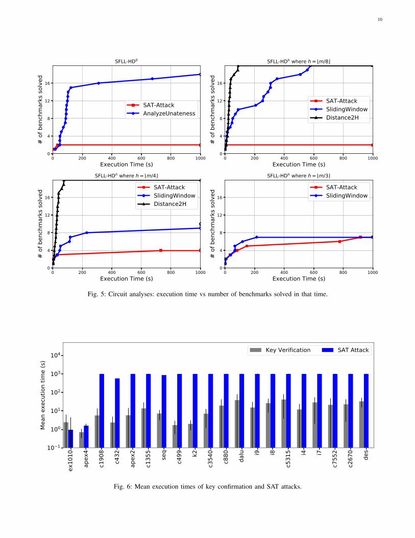
Figure 5 show the performance of the circuit analysesattacks on the benchmarks in our experimental framework.Four graphs are shown: the left most of which is for SFLL-HD0 while the remaining are for SFLL-HDh with varyingvalues of the Hamming Distance h. For each graph, the x-axis shows execution time while the y-axis shows the numberof benchmark circuits decrypted within that time.
The DISTANCE2H attack defeats all SFLL-HDh lockedcircuits for h = bm/8c and h = bm/4c. We repeated thisexperiment for the seven largest circuits with a key size of128 bits and the DISTANCE2H attack defeated all of theselocked circuits. Recall that DISTANCE2H is not applicablewhen 4h > m. ANALYZEUNATENESS is able to defeat 18 outof 20 TTLock circuits; the two remaining circuits are defeatedby the plain SAT attack. SLIDINGWINDOW is able to defeatall locked circuits for h = bm/8c, but does not perform aswell for larger values of h. This is because the SAT calls forlarger values of h are computationally harder as they involvemore adder gates in the Hamming Distance computation. Insummary, 65 out of 80 circuits (81%) are defeated by atleast one of our attack algorithms.
Among these 65 circuits for which the attack is successful,a unique key is identified for 58 circuits (90%). This means58 out of 80 circuits were defeated without oracle access(I/O access to an unlocked IC) — only functional analysis ofthe netlist was required. Among the seven circuits for whichmultiple keys were shortlisted, the attack shortlists two keyswhich are bitwise complements of each other for four circuits,three keys are shortlisted for two other circuits. One cornercases occurs for c432: 36 keys are shortlisted, this is still ahuge reduction from the initial space of 236 possible keys.
Recall that Algorithm DISTANCE2H is only applicable for0 < h ≤ bm/4c. Results show that DISTANCE2H defeatsall circuits for which it is applicable. SLIDINGWINDOW isapplicable for 0 < h < bm/2c, and results show that is lessscalable than DISTANCE2H because it has to make many morecalls to the SAT solver.
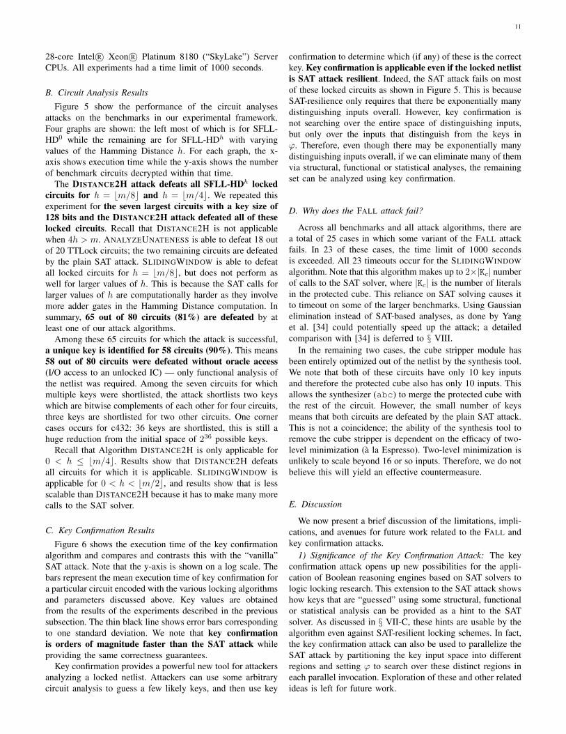
C. Key Confirmation Results
Figure 6 shows the execution time of the key confirmationalgorithm and compares and contrasts this with the “vanilla”SAT attack. Note that the y-axis is shown on a log scale. Thebars represent the mean execution time of key confirmation fora particular circuit encoded with the various locking algorithmsand parameters discussed above. Key values are obtainedfrom the results of the experiments described in the previoussubsection. The thin black line shows error bars correspondingto one standard deviation. We note that key confirmationis orders of magnitude faster than the SAT attack whileproviding the same correctness guarantees.
Key confirmation provides a powerful new tool for attackersanalyzing a locked netlist. Attackers can use some arbitrarycircuit analysis to guess a few likely keys, and then use key
confirmation to determine which (if any) of these is the correctkey. Key confirmation is applicable even if the locked netlistis SAT attack resilient. Indeed, the SAT attack fails on mostof these locked circuits as shown in Figure 5. This is becauseSAT-resilience only requires that there be exponentially manydistinguishing inputs overall. However, key confirmation isnot searching over the entire space of distinguishing inputs,but only over the inputs that distinguish from the keys inϕ. Therefore, even though there may be exponentially manydistinguishing inputs overall, if we can eliminate many of themvia structural, functional or statistical analyses, the remainingset can be analyzed using key confirmation.
D. Why does the FALL attack fail?
Across all benchmarks and all attack algorithms, there area total of 25 cases in which some variant of the FALL attackfails. In 23 of these cases, the time limit of 1000 secondsis exceeded. All 23 timeouts occur for the SLIDINGWINDOWalgorithm. Note that this algorithm makes up to 2×|Kc| numberof calls to the SAT solver, where |Kc| is the number of literalsin the protected cube. This reliance on SAT solving causes itto timeout on some of the larger benchmarks. Using Gaussianelimination instead of SAT-based analyses, as done by Yanget al. [34] could potentially speed up the attack; a detailedcomparison with [34] is deferred to § VIII.
In the remaining two cases, the cube stripper module hasbeen entirely optimized out of the netlist by the synthesis tool.We note that both of these circuits have only 10 key inputsand therefore the protected cube also has only 10 inputs. Thisallows the synthesizer (abc) to merge the protected cube withthe rest of the circuit. However, the small number of keysmeans that both circuits are defeated by the plain SAT attack.This is not a coincidence; the ability of the synthesis tool toremove the cube stripper is dependent on the efficacy of two-level minimization (a la Espresso). Two-level minimization isunlikely to scale beyond 16 or so inputs. Therefore, we do notbelieve this will yield an effective countermeasure.
E. Discussion
We now present a brief discussion of the limitations, impli-cations, and avenues for future work related to the FALL andkey confirmation attacks.
1) Significance of the Key Confirmation Attack: The keyconfirmation attack opens up new possibilities for the appli-cation of Boolean reasoning engines based on SAT solvers tologic locking research. This extension to the SAT attack showshow keys that are “guessed” using some structural, functionalor statistical analysis can be provided as a hint to the SATsolver. As discussed in § VII-C, these hints are usable by thealgorithm even against SAT-resilient locking schemes. In fact,the key confirmation attack can also be used to parallelize theSAT attack by partitioning the key input space into differentregions and setting ϕ to search over these distinct regions ineach parallel invocation. Exploration of these and other relatedideas is left for future work.
12
2) Applicability to other locking schemes: The structuralanalyses of the FALL attack are not specific to SFLL/TTLock.They can be used to identify the functionality restoration unitin all variants of SFLL including SFLL-fault [18]. This canhelp identify the circuit inputs for the protected cube. However,the identification of cube stripper and extracting the protectedcube via the functional analyses in § V is specific to SFLL-HDh and TTLock. Extending the analyses to find the protectedcube in SFLL-fault is an open problem for future work.
Note that the key confirmation attack is entirely independentof the structural and functional analyses and not at all specificto SFLL. It is an extension to the SAT attack where the attackeronly needs to somehow guess some set of keys or constraintover keys and can provide this to the SAT solver as a hint. Thesolver can use this information to greatly accelerate the searchfor the correct locking key. We believe this is of independentinterest for general attacks on combinational logic locking.
VIII. RELATED WORK
This section provides a brief overview of related attacks.Attacks on SFLL-HD: In concurrent work, Yang et al. [34]introduce a novel attack that also uses structural analysis ofthe netlist to identify the cube stripper. However, they usemanual inspection to look for signals connecting the cubestripper and the functionality restoration unit and rely on thetopological structure of these nodes to identify the output ofthe cube stripper. An important insight in their work is that thecube stripper in SFLL-HDh will have a tree-like structure witheach branch of the tree corresponding to a particular protectedpattern. They introduce an algorithm that is based on Gaussian-elimination to identify the key from the cube stripping unit.The main differences with our attack are the following. First,our analysis is completely automated, while Yang et al. usedmanual inspection to identify the cube stripping unit. Second,instead of using Gaussian elimination to identify the key, weuse Boolean function analyses (lemmas 2 and 3). Gaussianelimination has the advantage of being a polynomial timealgorithm while we rely on SAT-based analyses. Combiningtheir functional analyses with ours could potentially result ina more scalable attack on SFLL-HDh.
Alrahis et al. [1] also introduced novel attacks on SFLLconcurrently with this work. They use the reverse engineeringtool BSIM [26, 27] to identify the cube stripper and functional-ity restoration unit. Our structural and functional analyses aremore sophisticated than the implementations in BSIM becausethey are focused on SFLL-HD. The BSIM toolbox is basedon k-cut matching [7? ] and so it will miss structures whereintermediate sub-circuits have more than k inputs. Alrahis etal. work around this to some extent by reverse engineeringand then resynthesizing the circuit with a smaller gate library,but this method is not guaranteed to be foolproof.SAT-based Attacks: The key confirmation attack builds onrich body of literature in SAT-based attacks on logic locking,examples of which include the SAT attack [24], the DoubleDIP attack [20] and AppSAT [19]. As discussed in § VII-E,the main advantage of key confirmation is that it is an exactattack that can work on netlists resilient to the SAT, doubleDIP and AppSAT attacks.
IX. CONCLUSION
This paper proposed a set of Functional Analysis attackson Logic Locking (FALL attacks). We developed structuraland functional analyses to determine potential key values of alocked logic circuit. We then showed how these potential keyvalues could be verified using our key confirmation algorithm.
Our work has three important implications. First, we showedhow arbitrary structural and functional analyses can be syner-gistically combined with powerful Boolean reasoning enginesusing the key confirmation algorithm. Second, our attack wasshown to often succeed (90% of successful attempts in ourexperiments) without requiring oracle access to an unlockedcircuit. This suggests that logic locking attacks may be muchmore easily carried out than was previous assumed. Experi-ments showed that FALL defeated 65 out of 80 benchmarkcircuits locked using SFLL-HDh.
ACKNOWLEDGEMENTS
We would like to thank the anonymous reviewers for theirinsightful comments which helped improve the quality ofthis paper. We are also grateful to Intel Corp. for providingaccess to computational resources which were used to run theexperiments for this paper. This work was supported in partby the Science and Engineering Research Board, a unit of theDepartment of Science and Technology, Government of India.
REFERENCES
[1] L. Alrahis, M. Yasin, H. Saleh, B. Mohammad, and M. Al-Qutayri. Functional Reverse Engineering on SAT-Attack Re-silient Logic Locking. In 2019 IEEE International Symposiumon Circuits and Systems (ISCAS), pages 1–5, May 2019.
[2] Bengt Aspvall, Michael F. Plass, and Robert Endre Tarjan. Alinear-time algorithm for testing the truth of certain quantifiedboolean formulas. Information Processing Letters, 8(3):121 –123, 1979.
[3] A. Baumgarten, A. Tyagi, and J. Zambreno. Preventing ICPiracy Using Reconfigurable Logic Barriers. IEEE Design andTest, 27(1), Jan 2010.
[4] A. Biere. Lingeling, Plingeling and Treengeling. In A. Balint,A. Belov, M. Heule, and M. Jarvisalo, editors, Proceedings ofthe SAT Competition, 2013.
[5] P. Chakraborty, J. Cruz, and S. Bhunia. Surf: Joint structuralfunctional attack on logic locking. pages 181–190, May 2019.
[6] R.S. Chakraborty and S. Bhunia. Hardware Protection and Au-thentication Through Netlist Level Obfuscation. In IEEE/ACMInternational Conference on Computer-Aided Design, 2008.
[7] S. Chatterjee, A. Mishchenko, R. Brayton, X. Wang, andT. Kam. Reducing Structural Bias in Technology Mapping.In Proc. of the 2005 IEEE/ACM International Conf. on Comp.-Aided Design, ICCAD ’05, pages 519–526, 2005.
[8] Stephen A Cook. The complexity of theorem-proving proce-dures. In Proceedings of the third annual ACM symposium onTheory of computing, pages 151–158. ACM, 1971.
[9] Defense Science Board Task Force on High Perfor-mance Microchip Supply. http://www.acq.osd.mil/dsb/reports/ADA435563.pdf, 2005.
[10] S. Dupuis, P.-S. Ba, G. Di Natale, M.-L. Flottes, andB. Rouzeyre. A Novel Hardware Logic Encryption Techniquefor Thwarting Illegal Overproduction and Hardware Trojans. InIEEE International On-Line Testing Symposium, 2014.
[11] IHS Technology Press Release: Top 5 most counterfeitedparts represent a $169 billion potential challenge for globalsemiconductor industry. https://technology.ihs.com/405654/top-
13
5-most-counterfeited-parts-represent-a-169-billion-potential-challenge-for-global-semiconductor-market, 2012.
[12] Alan Mishchenko. ABC: System for Sequential Logic Synthesisand Formal Verification. https://github.com/berkeley-abc/abc,2018.
[13] M. Pecht and S. Tiku. Bogus! Electronic manufacturing andconsumers confront a rising tide of counterfeit electronics. IEEESpectrum, May 2006.
[14] S.M. Plaza and I.L. Markov. Solving the third-shift problem inic piracy with test-aware logic locking. In IEEE Transactionson CAD of Integrated Circuits and Systems, 2015.
[15] J. Rajendran, Y. Pino, O. Sinanoglu, and R. Karri. SecurityAnalysis of Logic Obfuscation. In Proceedings of the DesignAutomation Conference, 2012.
[16] J. Rajendran, H. Zhang, C. Zhang, G. S. Rose, Y. Pino,O. Sinanoglu, and R. Karri. Fault Analysis-Based LogicEncryption. IEEE Transactions on Computers, 64(2), Feb 2015.
[17] J. A. Roy, F. Koushanfar, and I. L. Markov. EPIC: Ending Piracyof Integrated Circuits. In Proceedings of Design, Automationand Test in Europe, 2008.
[18] Abhrajit Sengupta, Mohammed Thari Nabeel, MuhammadYasin, and Ozgur Sinanoglu. Atpg-based cost-effective, securelogic locking. In 36th IEEE VLSI Test Symposium, VTS 2018,San Francisco, CA, USA, April 22-25, 2018, pages 1–6, 2018.
[19] K. Shamsi, M. Li, T. Meade, Z. Zhao, D. Z. Pan, and Y. Jin.Appsat: Approximately deobfuscating integrated circuits. In2017 IEEE International Symposium on Hardware OrientedSecurity and Trust (HOST), 2017.
[20] Yuanqi Shen and Hai Zhou. Double DIP: Re-EvaluatingSecurity of Logic Encryption Algorithms. In Proceedings ofthe on Great Lakes Symposium on VLSI 2017, 2017.
[21] Semiconductor Industry Association: Anti-CounterfeitingWhitepaper One-Pager. http://www.semiconductors.org/clientuploads/directory/DocumentSIA/Anti%20Counterfeiting%20Task%20Force/ACTF%20Whitepaper%20Counterfeit%20One%20Pager%20Final.pdf, 2013.
[22] Deepak Sirone and Pramod Subramanyan. Fall Attacks Source.https://bitbucket.org/spramod/fall-attacks, 2018.
[23] Deepak Sirone and Pramod Subramanyan. Functional AnalysisAttacks on Logic Locking. In Proceedings of Design Automa-tion and Test in Europe (DATE), 2019.
[24] P. Subramanyan, S. Ray, and S. Malik. Evaluating the SecurityLogic Encryption Algorithms. In 2015 IEEE InternationalSymposium on Hardware Oriented Security and Trust (HOST),2015.
[25] Pramod Subramanyan and Sayak Ray. SAT and Key Confirma-tion Attacks Repository . https://bitbucket.org/spramod/host15-logic-encryption, 2019.
[26] Pramod Subramanyan, Nestan Tsiskaridze, Wenchao Li, AdriaGascon, Wei Yang Tan, Ashish Tiwari, Natarajan Shankar,Sanjit A. Seshia, and Sharad Malik. Reverse Engineering DigitalCircuits Using Structural and Functional Analyses. IEEE Trans.Emerging Topics Comput., 2(1):63–80, 2014.
[27] Pramod Subramanyan, Nestan Tsiskaridze, Kanika Pasricha,Dillon Reisman, Adriana Susnea, and Sharad Malik. Reverseengineering digital circuits using functional analysis. In Design,Automation and Test in Europe, DATE 13, Grenoble, France,March 18-22, 2013, pages 1277–1280, 2013.
[28] R. Torrance and D. James. The State-of-the-Art in IC ReverseEngineering. In Proceedings of the 11th International Workshopon Cryptographic Hardware and Embedded Systems, 2009.
[29] G. S. Tseitin. On the complexity of derivation in propositionalcalculus. In J. Siekmann and G. Wrightson, editors, Automationof Reasoning 2: Classical Papers on Computational Logic 1967-1970, pages 466–483. Springer, Berlin, Heidelberg, 1983.
[30] J. Villasenor and M. Tehranipoor. The Hidden Dangers of Chop-Shop Electronics. IEEE Spectrum, Sep 2013.
[31] Y. Xie and A. Srivastava. Mitigating SAT Attack on Logic Lock-ing. In International Conference on Cryptographic Hardware
and Embedded Systems, 2016.[32] Y. Xie and A. Srivastava. Anti-sat: Mitigating sat attack on
logic locking. IEEE Transactions on Computer-Aided Designof Integrated Circuits and Systems, 2018.
[33] X. Xu, B. Shakya, M.M Tehranipoor, and D. Forte. NovelBypass Attack and BDD-based Tradeoff Analysis Against allKnown Logic Locking Attacks. In Cryptology ePrint Archive,2017.
[34] F. Yang, M. Tang, and O. Sinanoglu. Stripped functionalitylogic locking with hamming distance-based restore unit (sfll-hd) unlocked. IEEE Transactions on Information Forensicsand Security, 14(10):2778–2786, Oct 2019.
[35] M. Yasin, B. Mazumdar, S.S. Ali, and Sinanoglu O. SecurityAnalysis of Logic Encryption against the Most Effective Side-Channel Attack: DPA. In IEEE International Symposiumon Defect and Fault Tolerance in VLSI and NanotechnologySystems, 2015.
[36] M. Yasin, B. Mazumdar, J. J. V. Rajendran, and O. Sinanoglu.SARLock: SAT attack resistant logic locking. In 2016 IEEEInternational Symposium on Hardware Oriented Security andTrust (HOST), pages 236–241, 2016.
[37] M. Yasin, B. Mazumdar, O. Sinanoglu, and Rajendran J. Re-moval Attackson Logic Locking and Camouflaging Techniques.In IEEE Transactions on Emerging Topics in Computing, 2017.
[38] M. Yasin, S.M. Saeed, J. Rajendran, and O. Sinanoglu. Activa-tion of logic encrypted chips: Pre-test or post-test? In Design,Automation Test in Europe., 2016.
[39] Muhammad Yasin, Abhrajit Sengupta, Mohammed ThariNabeel, Mohammed Ashraf, Jeyavijayan (JV) Rajendran, andOzgur Sinanoglu. Provably-secure logic locking: From theory topractice. In Proceedings of the 2017 ACM SIGSAC Conferenceon Computer and Communications Security, CCS ’17, 2017.
[40] Muhammad Yasin, Abhrajit Sengupta, Benjamin CarrionSchafer, Yiorgos Makris, Ozgur Sinanoglu, and Jeyavi-jayan (JV) Rajendran. What to lock?: Functional and parametriclocking. In Proceedings of the on Great Lakes Symposium onVLSI 2017, 2017.
Deepak Sirone received the B.Tech. degree fromthe National Institite of Technology, Calicut in 2016and the M.Tech. degree from the Indian Instititeof Technology, Kanpur in 2019. He is currentlypursuing his Ph.D. degree from the Department ofComputer Sciences at the University of Wisconsin-Madison. His research interest is in systems security.
Pramod Subramanyan received the B.E. degreefrom the R. V. College of Engineering in 2006,the M.Sc. (Engg.) degree from the Indian Instituteof Science in 2011. He obtained a Ph.D. degreefrom the Department of Electrical Engineering atPrinceton University in 2017. He is currently anassistant professor at the Department of ComputerScience and Engineering at the Indian Institute ofTechnology, Kanpur. His research interests lie at theintersection of systems security and formal methods.
14
APPENDIX: PROOFS
This appendix proves the lemmas in § V and VI.
(Lemma 2) Suppose X1 = 〈x11, . . . , x1m〉, X2 =〈x21, . . . , x2m〉, Kc = 〈k1, . . . , km〉 and striph(Kc)(X
1) = 1 =striph(Kc)(X
2). If HD(X1, X2) = 2h, then for every j suchthat x1j = x2j , we must have x1j = x2j = kj .
Proof: The proof is by induction on h. The base case forh = 0 is clearly true, because in this case striph(Kc)(X
1) =striph(Kc)(X
2) = 1 iff Kc = X1 = X2. This implies that x1j =x2j = kj for all j.
In the inductive step, assume the lemma holds for h − 1.Consider some arbitrary X1, X2 such that striph−1(Kc)(X
1) =striph−1(Kc)(X
2) = 1 and HD(X1, X2) = 2h − 2. Supposethere exist i and l with i 6= l and x1i = x2i and x1l = x2l .By the lemma for h − 1, we have x1i = x2i = ki and x1l =x2l = kl. Now consider the vectors Y1 = 〈y11, . . . , y1m〉 andY2 = 〈y21, . . . , y2m〉 which are constructed as follows. Y1 isthe same as X1 except that index i is flipped, while Y2 isthe same as X2 except at index l which is flipped. Noticethat striph(Kc)(Y
1) = striph(Kc)(Y2) = 1 because each of
these vectors differ from the protected cube on one more index(either i or l). Further HD(Y1, Y2) = 2h because i 6= l. We seethat for all j such that y1j = y2j , we must have y1j = y2j = kjbecause these indices are the same in both Y1 and X1 as wellas Y2 and X2 respectively. In other words, we have shown thelemma also holds for h if it holds for h− 1.
(Lemma 3) Consider the assignments X1 = 〈x11, . . . , x1m〉and X2 = 〈x21, . . . , x2m〉. Let Kc = 〈k1, . . . , km〉 as before.The formula striph(Kc)(X
1) = 1 ∧ striph(Kc)(X2) = 1 ∧
HD(X1, X2) = 2h∧ x1j = x2j ∧ x1j = b is satisfiable iff b = kj .Proof: The proof of this lemma is a direct consequence
of Lemma 2. Note that the above statement of the lemma isequivalent to saying that the formula striph(Kc)(X
1) = 1 ∧striph(Kc)(X
2) = 1∧HD(X1, X2) = 2h∧ x1j = x2j ∧ x1j = b isunsatisfiable iff b 6= kj . This follows from Lemma 2.
(Lemma 1) The cube stripping function for TTLock/SFLL-HD0 is unate in every variable xi. Further, it is positive unatein xi if ki = 1 and negative unate in xi if ki = 0.
Proof: The proof is by induction on the number of literalsin the protected cube. In the base case, the protected cube hasonly one literal; it is either xi or ¬xi. The function f(xi)
.= xi
is positive unate in the variable xi while the function f(xi).=
¬xi is negative unate in the variable xi.
Now consider the inductive step. We have cubeC(x1, . . . , xi−1) consisting of i− 1 literals which is assumedto be unate in all its variables. We have to show that boththe cubes C(x1, . . . , xi−1) ∧ xi and C(x1, . . . , xi−1) ∧ ¬xiare unate in the variable xi. Let us consider only the cubeC(x1, . . . , xi−1) ∧ xi w.l.o.g as the argument is symmetricfor C(x1, . . . , xi−1) ∧ ¬xi. This cube is positive unate in thevariable xi. For all the other variables in C(x1, . . . , xi−1),since C is unate in each of those variables, it is also unate inC(x1, . . . , xi−1) ∧ xi for those variables.
(Lemma 4) Algorithm 4 terminates and returns either (i)the key Kc or (ii) ⊥. The former occurs iff Kc |= ϕ and∀X. C(X, Kc, Y ) ⇐⇒ Y = oracle(X). The latter occurs iffno such Kc exists.
Proof : Each iteration of the loop rules out at least onedistinguishing input. Since there are only a finite numberof distinguishing inputs of the circuit, this guarantees thealgorithm will terminate. If the algorithm returns a key Kc, thenthis key is satisfies Pi, so this ensures that Kc |= ϕ. Further,this also means there are no distinguishing inputs for Kc andany other key as line 10 was UNSAT. This guarantees that Kcis the correct key. If the algorithm returns ⊥, it means thatthere is no input consistent with ϕ(K1) and the input/outputpatterns from the oracle.