Embed Size (px)
Citation preview
Vahé Karamian
35
Chapter 2 – Brief Introduction to Unity IDE
Interface Overview
Before we can get started with any of the cool aspects of Unity, we
would need to get ourselves familiar with the environment. At the time
of writing, Unity 5.3 was the latest public release. Hence we are going
to be concentrating our efforts on Unity 5.3.
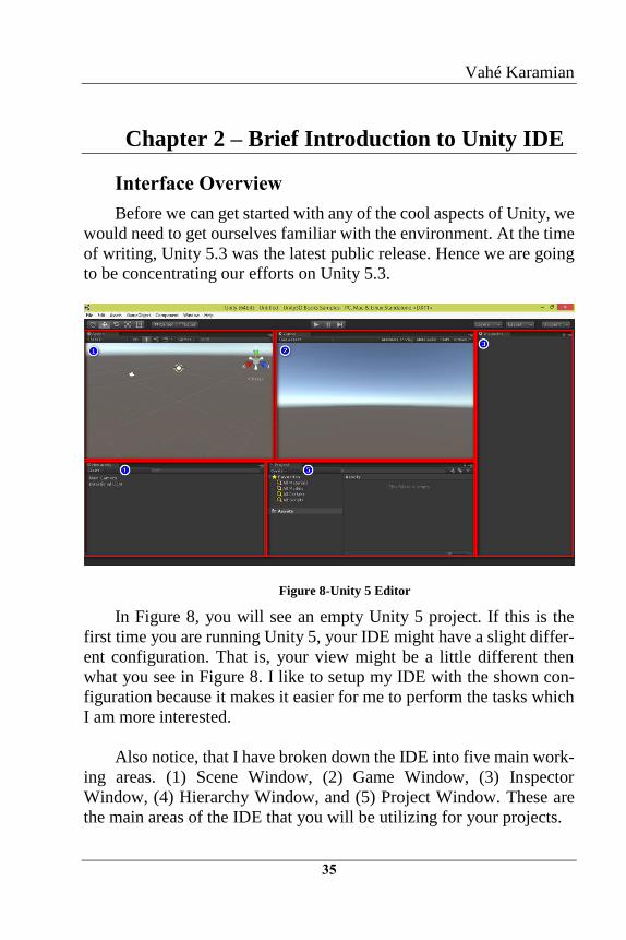
Figure 8-Unity 5 Editor
In Figure 8, you will see an empty Unity 5 project. If this is the
first time you are running Unity 5, your IDE might have a slight differ-
ent configuration. That is, your view might be a little different then
what you see in Figure 8. I like to setup my IDE with the shown con-
figuration because it makes it easier for me to perform the tasks which
I am more interested.
Also notice, that I have broken down the IDE into five main work-
ing areas. (1) Scene Window, (2) Game Window, (3) Inspector
Window, (4) Hierarchy Window, and (5) Project Window. These are
the main areas of the IDE that you will be utilizing for your projects.
Unity 3D – Game Programming Intro
36
At the moment as you can see, the IDE is pretty uninteresting.
That’s because we do not have anything interesting going on in the de-
signer, it is just a blank canvas waiting for your creative ideas! Let’s
get a better understanding of what each of these regions will be used
for in a nut-shell:
Scene View
The Scene View is your interactive sandbox. You will use the
Scene View to select and position your GameObjects. These includes
the player, the camera, your enemies, and everything else that will be
used to generate your level. Maneuvering and manipulating objects
within the Scene View are some of the most important functions in
Unity, so it is important to learn how to perform them in an efficient
way. As we go along the examples, more hints will be provided to im-
prove and increase productivity.
Game View
The Game View is rendered from the Camera(s) in your game. It
is representative of your final, published game. You will need to use
one or more Cameras to control what the player actually sees when they
are playing your game. You can also quickly change the aspect ratio of
the Game View window to quickly see how your game will look on
different resolutions and screen sizes. One other great feature of the
Game View window is that you can actually get the Rendering Statis-
tics which is a great utility for checking the performance of your game.
This data can then be used for optimizing graphics performance for
more complex scenes.
The Inspector
The Inspector Window displays detailed information about your
currently selected GameObject and all of the attached Components and
their properties. Within the Inspector Window, you can modify the
functionality of GameObjects in your scene. Any property that is dis-
played in the Inspector can be directly modified. This includes script
variable. You can also use the Inspector to change properties to see the
actual result during runtime! The Inspector is another part of the Unity
Unity 3D – Game Programming Intro
38
Creating Our First Game Object
Unity 3D is not a 3D Modeling software, so do not expect to create
sophisticated models using Unity 3D. Unity 3D is a Game Engine pri-
marily, that also provides you with some flexibility on modifying and
or creating simple 3D content! For your 3D modeling needs, you will
need to work with software such as 3D Studio Max, Maya, Rhino and
etc… Generally speaking, your models will be created by a 3D Modeler
and Designer and you will import them and use them inside your game.
By default, there are several primitives that can be created out of
the box. These are the Cube primitive, the Sphere primitive, the Cap-
sule primitive, the Cylinder primitive, the Plane primitive and the Quad
primitive. For the purpose of this demonstration we will place a Cube
primitive in the scene.
NOTE: The process of creating and modifying any primitive type
is the same. In fact, the modification, as far as the transform is con-
cerned is the same for each Game Object.
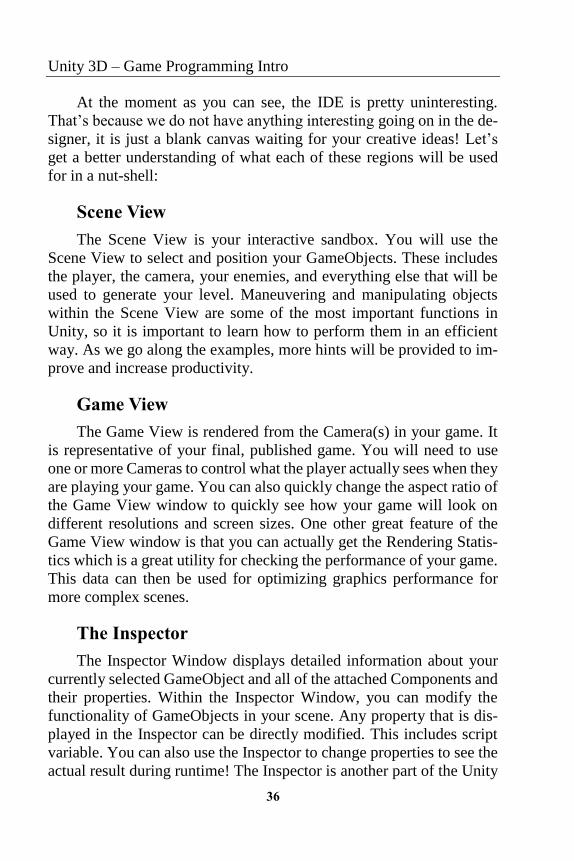
Figure 9-Cube Primitive
In order to create a Cube primitive, from the main menu select
GameObject->3D Object->Cube. This action will result in placing a
cube in your active scene. Before we continue further, let’s go ahead
Unity 3D – Game Programming Intro
40
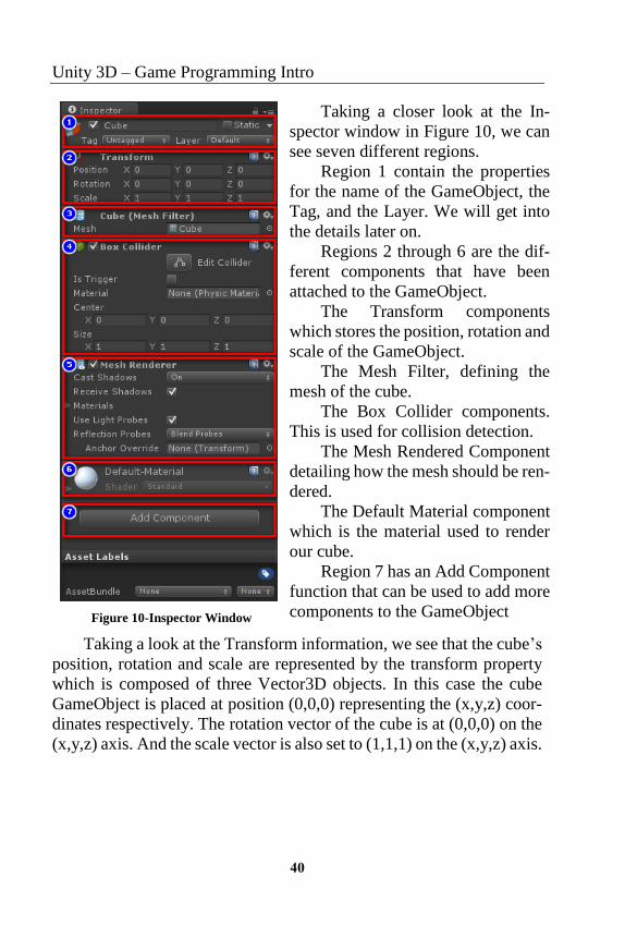
Figure 10-Inspector Window
Taking a closer look at the In-
spector window in Figure 10, we can
see seven different regions.
Region 1 contain the properties
for the name of the GameObject, the
Tag, and the Layer. We will get into
the details later on.
Regions 2 through 6 are the dif-
ferent components that have been
attached to the GameObject.
The Transform components
which stores the position, rotation and
scale of the GameObject.
The Mesh Filter, defining the
mesh of the cube.
The Box Collider components.
This is used for collision detection.
The Mesh Rendered Component
detailing how the mesh should be ren-
dered.
The Default Material component
which is the material used to render
our cube.
Region 7 has an Add Component
function that can be used to add more
components to the GameObject
Taking a look at the Transform information, we see that the cube’s
position, rotation and scale are represented by the transform property
which is composed of three Vector3D objects. In this case the cube
GameObject is placed at position (0,0,0) representing the (x,y,z) coor-
dinates respectively. The rotation vector of the cube is at (0,0,0) on the
(x,y,z) axis. And the scale vector is also set to (1,1,1) on the (x,y,z) axis.
Unity 3D – Game Programming Intro
42
The next components representing the Mesh Filter and Mesh Ren-
derer will be discussed later in the chapters. The only thing you should
be aware of is that these components are the actual representation of
the wireframe and the way the GameObject will be rendered on the
scene. We will also discuss the Collider component in later chapters
when we are building our game demos. For now you should only be
aware that colliders are used for any collision detection, and they are
pretty important to understand and configure properly. Especially in
more complex models.
The Material component is used to define the type of material that
will be applied to the selected GameObject. Materials are used in con-
junction with Mesh Renderers, Particle Systems and other rendering
components. They play an essential part in defining how your object is
displayed. The properties that a Material’s Inspector window displays
are determined by the Shader that the Material uses. A shader is a spe-
cialized kind of graphics program that determines how texture and
lighting information are combined to generate the pixels of the rendered
object onscreen. We won’t be covering shaders in this book, as it is not
our primary topic and there are far better suited books to discuss and
cover the topic.
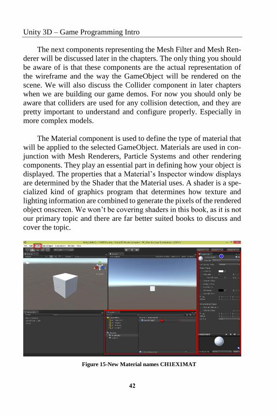
Figure 15-New Material names CH1EX1MAT
Unity 3D – Game Programming Intro
44
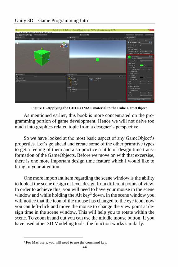
Figure 16-Applying the CH1EX1MAT material to the Cube GameObject
As mentioned earlier, this book is more concentrated on the pro-
gramming portion of game development. Hence we will not delve too
much into graphics related topic from a designer’s perspective.
So we have looked at the most basic aspect of any GameObject’s
properties. Let’s go ahead and create some of the other primitive types
to get a feeling of them and also practice a little of design time trans-
formation of the GameObjects. Before we move on with that excersise,
there is one more important design time feature which I would like to
bring to your attention.
One more important item regarding the scene window is the ability
to look at the scene design or level design from different points of view.
In order to achieve this, you will need to have your mouse in the scene
window and while holding the Alt key3 down, in the scene window you
will notice that the icon of the mouse has changed to the eye icon, now
you can left-click and move the mouse to change the view point at de-
sign time in the scene window. This will help you to rotate within the
scene. To zoom in and out you can use the middle mouse button. If you
have used other 3D Modeling tools, the function works similarly.
3 For Mac users, you will need to use the command key.
Vahé Karamian
45
Go ahead and zoom a little out in the scene view so you can see a
larger area to play around with. Next go ahead and create another cube
GameObject. By default, every GameObject will be placed at the origin
(0,0,0). Let’s make some modifications to the transform of the newly
created cube. Also note that the new Cube GameObject is named Cube
(1), in order for you to change the name of the newly created GameOb-
ject, select it and from the Inspector Window rename the object to
Cube2. You can also rename a GameObject from the Hierarchy win-
dow by selecting it and clicking it once or pressing the F2 key. This
works similar to your file system.
Let’s go ahead and use the transform tools to move Cube2 to posi-
tion (2,0,0) and then scale it down so that it is half its original size. You
can do so by selecting the red-arrow representing the x-axis, refer to
Figure 12, to drag it in the positive or negative direction. You will no-
tice that moving objects to specific locations is not going to be as easy
with the transform tool if you need to get to very specific positions such
as (2.33,0,0). For these type of coordinates, it will be best to use the
Inspector Window and directly input the position coordinates.
Now let’s scale our GameObject to half it’s size. Select the scale
tool and use the indicators, refer to Figure 14, to get the size of the
object down to half its size. Note that you will have to do this on all 3-
axis respectively. As you can see, scaling the object to exactly 0.5 on
all the three axis is hard! Make life easy and use the Inspector Window
to enter in the numerical values for the scale vector to be (0.5,0.5,0.5).
One last transformation and we will be good with this exercise.
Let’s go ahead and rotate Cube2 by 33 degrees on the xyz-axis. Select
the rotation tool and use the indicators, refer to Figure 13, to rotate the
object. If you have followed the steps your screen should resemble Fig-
ure 17.
Vahé Karamian
47
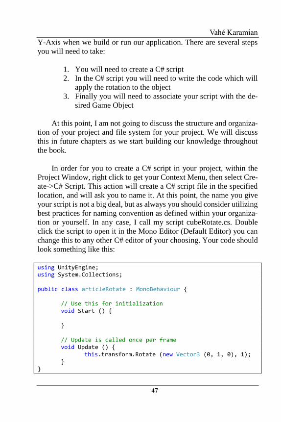
Y-Axis when we build or run our application. There are several steps
you will need to take:
1. You will need to create a C# script
2. In the C# script you will need to write the code which will
apply the rotation to the object
3. Finally you will need to associate your script with the de-
sired Game Object
At this point, I am not going to discuss the structure and organiza-
tion of your project and file system for your project. We will discuss
this in future chapters as we start building our knowledge throughout
the book.
In order for you to create a C# script in your project, within the
Project Window, right click to get your Context Menu, then select Cre-
ate->C# Script. This action will create a C# script file in the specified
location, and will ask you to name it. At this point, the name you give
your script is not a big deal, but as always you should consider utilizing
best practices for naming convention as defined within your organiza-
tion or yourself. In any case, I call my script cubeRotate.cs. Double
click the script to open it in the Mono Editor (Default Editor) you can
change this to any other C# editor of your choosing. Your code should
look something like this:
using UnityEngine; using System.Collections; public class articleRotate : MonoBehaviour { // Use this for initialization void Start () { } // Update is called once per frame void Update () { this.transform.Rotate (new Vector3 (0, 1, 0), 1); } }
Unity 3D – Game Programming Intro
48
A few things to explain before we move forward. Each script that
you create will by default inherit from MonoBehaviour. We will dis-
cuss this class at a later point. Each script that you create will also have
two functions defined as: Start() and Update().
The Start() function will be run only once at the start of the pro-
gram. So any logic and data initializations that you need or want to do
can be placed in the Start() function.
The Update() function is where most of the magic happens. This
is the function that gets called continuously throughout the life of your
game or simulation. This is the function where you will update your
game objects. In short it is the function which will be called each frame
before rendering the scene.
The line this.transform.Rotate (new Vector3 (0, 1, 0), 1); will per-
form the desired rotation we are looking for on the given object it is
applied to. Without getting too much into the details and the behind the
scene complication of this function. We can utilize the Rotate function
defined on the transform component of our object to pass in a Vector3
object, representing our (X,Y,Z), and the rotation angle.
Since we are planning to rotate on the Y-Axis, we have to define
our Vector3 as (0,1,0). The function will do all of the necessary trans-
formations and handle the computation for you. The next parameter is
the rotation angle, which we have defined as 1.
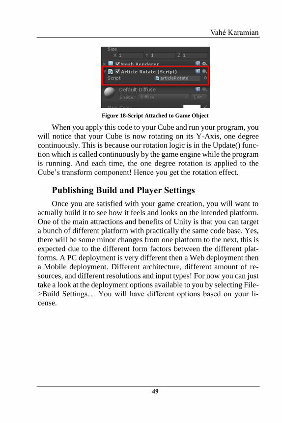
There are several ways to apply a script to a Game Object. The
simplest way would be to drag and drop your script onto the desired
game object on the scene. After you have applied the script, in the In-
spector Windows, you will see that the script is a component of the
cube.
Vahé Karamian
49
Figure 18-Script Attached to Game Object
When you apply this code to your Cube and run your program, you
will notice that your Cube is now rotating on its Y-Axis, one degree
continuously. This is because our rotation logic is in the Update() func-
tion which is called continuously by the game engine while the program
is running. And each time, the one degree rotation is applied to the
Cube’s transform component! Hence you get the rotation effect.
Publishing Build and Player Settings
Once you are satisfied with your game creation, you will want to
actually build it to see how it feels and looks on the intended platform.
One of the main attractions and benefits of Unity is that you can target
a bunch of different platform with practically the same code base. Yes,
there will be some minor changes from one platform to the next, this is
expected due to the different form factors between the different plat-
forms. A PC deployment is very different then a Web deployment then
a Mobile deployment. Different architecture, different amount of re-
sources, and different resolutions and input types! For now you can just
take a look at the deployment options available to you by selecting File-
>Build Settings… You will have different options based on your li-
cense.


![[Paris Unity meetup] - Unity 3D en entreprise](https://img.pdfslide.us/doc/110x75/55a64ec51a28ab123f8b45ab/paris-unity-meetup-unity-3d-en-entreprise.jpg)