Embed Size (px)
Citation preview
AIRBAG SYSTEMS
SEMINAR REPORT
SUBMITTED BY
REGEIF MOHAMMED ALI(AXALEME040)
In partial fulfilment for the award of the degree
Of
BACHELOR OF TECHNOLOGY
IN
MECHANICAL ENGINEERING
AXIS COLLEGE OF ENGINEERING AND TECHNOLOGY, AMBANOLY
UNIVERSITY OF CALICUT, KERALA
2015

DEPARTMENT OF MECHANICAL ENGINEERING
CERTIFICATE
This is to certify that this project report titled
AIRBAG SYSTEMS
Was prepared and presented by
REGEIF MOHAMMED ALI (AXALEME040)
of the eighth Semester Mechanical Engineering
in partial fulfilment of requirement for the award of
Degree of Bachelor of Technology in Mechanical Engineering under the University of
Calicut during the year 2011-2015
Asst Prof .ABILASH .K.J Prof .P.S. SIVARAMAN
Seminar Guide H.O.D
Dept .of . Mechanical Engg

iii
ACKNOWLEDGEMENT
No achievements can be made by individuals alone .it would be incorrect if i don't
thank the people who an important role in finishing the seminar report. First and foremost i
would like to thank god almighty for blessing me with his grace and taking my endeavour to
a successful culmination. I would like to show gratitude to esteemed principal Prof. Dr.
Anslam Raj who helped me in every possible ways. I would like to show gratitude to my
Head Of the Department Of mechanical Engineering Prof P.S Sivaraman, who helped me in
every possible ways. I express my heartfelt thanks to our internal guide & inspiration Asst.
Prof Abhilash .K J, for his valuable support, guidance & constructive ideas throughout the
seminar.I thank all the lecturer & non-supporting staff for their help & I would like to thank
my friends who helped me for the successful completion
iii
ABSTRACT
The present paper represents a brief review of life saving system in roll- over accidents, while
driving on the road by a four wheeler. An Airbag is an automotive safety restraint system for an
occupant as well as passengers. The system consists of a flexible fabric envelope or cushion, designed
to inflate rapidly during an automobile collision. Its purpose is to cushion occupants during a crash and
provide protection to their bodies when they strike interior objects such as the steering wheel or a
window etc. Thus it lowers the number of injuries by reducing the force exerted by steering wheel,
windows and the dashboard at any point on the body. Continuing research and developments are going
on in its module design, combustible material, air bag fabric design and material, coating etc. in
making this life saving safety device further efficient. However, success of any safety restraint device
depends on its correct implementation and certain safety rules to be followed
iii
LIST OF CONTENTS
CHAPTERS TITLE PAGENO.
ACKNOWLEDGEMENT iii
ABSTRACT iv
LIST OF CONTENTS v
LIST OF TABLES vii
LIST OF FIGURES viii
LIST OF ABBREVIATIONS x
1 INTRODUCTION 1
2 LITERATURE REVIEW 2
2.1 OVER VIEW 2
2.2 HISTORY 2
2.3 CHEMISTRY OF AIRBAG 5
3 MAIN PARTS 7
3.1 AIRBAG MODULE 7
3.1.1 AIR BAG PRODUCTION PROCESS 8
3.1.2 RAW MATERIALS USED IN AIR BAG 8
3.2 SENSORS 10
3.2.1 MASS TYPE SENSOR 10
3.2.2 ROLLER-TYPE SENSOR 11
3.3 AIRBAG CONTROL UNIT 12
4 WORKING 15
5 AIRBAG TYPES 16
5.1 FRONTAL AIR BAGS 16
5.2 HEAD PROTECTION BAGS 17
5.2.1 SIDE CURTAIN AIRBAGS 18
5.3 SIDE IMPACT AIR BAGS 19
5.4 OCCUPANT POSITIONING AIR BAGS 20
5.4.1 KNEE BAGS OR BOLSTERS 21
5.5 CARPET BAGS 21
5.6 ANTI-SLIDE SEAT BAGS 22
5.7 MISCELLANEOUS AIRBAGS 23

iii
6 AIRBAG RISKS 26
7 CONCLUSION 27
8 REFERANCE 28

iii
LIST OF TABLES
TABLE NO: TITLE PAGE NO:
2.1 Showing the same statics for belted, non-belted and overall 4
2.2 Showing chemical reactions inside and airbag 6
3.1 properties of these commercially used fabrics 8

iii
LIST OF FIGURES
FIGURE NO: TITLE PAGE NO:
1.1 Driver and front passenger air bag 1
2.1 Statistics for Airbag Application in Vehicles 4
2.2 Airbag Unit growth in Vehicles, by Region- 2000 to
20005
5
2.3 Chemicals inside the airbags 5
3.1 ON/OFF switch of air bag system 7
3.2 Air bag fabric productions flow-chart 8
3.3 Mass type sensor 11
3.4 Roller-type sensor 11
3.5 Airbag control unit 12
5.1 Driver side airbag 16
5.2 Shows the deployed first stage of a air bag 17
5.3 Head protection airbags 18
5.4 Side curtain airbags 19
5.5 Side impact airbags 19
5.6
Left shows an identification stamp. On the right is a
picture of a deployed knee bag.
21
5.7 Picture of a deployed carpet bag 22
5.8 Anti-slide Seat bags 22
5.9 Air bag in the head rest of the rear seat in a passenger car. 23
5.10 Air bag installed in the seat belt. 23
5.11 Pedestrians protection airbags 23
5.12 This air bag to deflect the path of the rider up and
over the impacted vehicle
24
5.13 Airbag vest is available to motorcycle riders 24

SEMINAR REPORT 2015 AIRBAG SYSTEMS
Dept. of Mechanical Engg. 9 AXIS CET
LIST OF ABBREVIATIONS
1. DOT - Department Of Transportation
2. SRS - Supplemental Restraint System
3. US - United States
4. NaN3 - Sodium Aside
5. Na - Sodium
6. N2 - Nitrogen gas
7. KNO3 - Potassium nitrate
8. K2O - Potassium oxide
9. SiO2 - Silicon dioxide
10. Na2K2SiO4 - Alkaline silicate glass
11. UV - Ultraviolet
12. ECU - Electronic Control Unit
13. FMVSS - Federal Motor Vehicle Safety Std
14. ITS - Inflatable Tubular Systems
15. HPS - Head Protection Systems
16. NHTSA - National Highway Safety Admin

SEMINAR REPORT 2015 AIRBAG SYSTEMS
Dept. of Mechanical Engg. 10 AXIS CET
CHAPTER 1
INTRODUCTION
Fig no: 1.1 Driver and front passenger air bag
For many years, the trusty seat belt provided the sole form of passive restraint in our cars. Seat
belts have been proven to be effective in saving lives and preventing or lessening injuries in
automobile accidents.. The first passive restraints were modifications of seat belts themselves; the belts
were coordinated with operations of opening the car doors and starting the automobile, which caused
belts built into tracks in the doors to wrap around the driver or passenger when the seat was occupied.
Concurrently, the airbag was devised as a secondary form of passive restraint during impact.
Air Bags have been under development for many years. They were initially used and designed
to be used in fighter planes during world war second. In the 1980’s the first commercial air bags
appeared in automobiles. Since 1988, all new cars have been required to have air bags on both driver
and passenger sides. To date, Statistics show that air bags reduce the risk of dying in a direct frontal
crash by 30 percent. Other than steering Wheel mounted or Dash board mounted bags, there are seat-
mounted and door mounted side air-bags. Air bags were invented as the result of serious government
discussions and industry research and tests.

SEMINAR REPORT 2015 AIRBAG SYSTEMS
Dept. of Mechanical Engg. 11 AXIS CET
CHAPTER 2
LITERATURE REVIEW
2.1 OVERVIEW
Airbags are considered as passive device because no action by the vehicle occupant is required
to activate or use the airbag This is in contrast to seat belts, which are considered active devices
because the vehicle occupant must act to enable them. Note that this is not related to active and passive
safety, which are, respectively, systems designed to prevent accidents in the first place and systems
designed to minimize accidents once they occur. For example, the car's Anti-lock Braking System will
qualify as an active-safety device while both its seatbelts and airbags will qualify as passive-safety,
which are, respectively, systems designed to prevent accidents in the first place and systems designed
to minimize accidents once they occur. For example, the car's Anti-lock Braking System will qualify
as an active-safety device while both its seatbelts and airbags will qualify as passive-safety devices.
Further terminological confusion can arise from the fact that passive devices and systems those
requiring no input or action by the vehicle occupant can themselves operate in an active manner; an
airbag is one such device. Vehicle safety professionals are generally careful in their use of language to
avoid this sort of confusion, though advertising principles sometimes prevent such syntactic caution in
the consumer marketing of safety features. Various manufacturers have over time used different terms
for airbags. General Motors' first bags, in the 1970s, were marketed as the Air Cushion Restraint
System. Common terms in North America include Supplemental Restraint System and Supplemental
Inflatable Restraint, these terms reflect the airbag system's nominal role as a supplement to active
restraints, i.e., seat belts.
2.2 HISTORY
The first concepts for an automatically inflating air cushion used as an impact protection for car
passengers were discussed in the sixties, approximately 10 years after corresponding patents had been
granted . John HETRICK'S patent describes a general airbag system in which a self-opening airbag is
automatically inflated following a sudden deceleration of the vehicle. In the USA ordinances FMVSS
208 was passed in the middle of the sixties against the background of increasing numbers of accidents,
to improve vehicle safety, thereby it called Safety Act. A bundle of new ordinances were planned to
improve safety in traffic. It was not until 1984, following long and controversial discussions, that an
agreement could be reached on the introduction of a passive restraint system on September 1, 1989 for

SEMINAR REPORT 2015 AIRBAG SYSTEMS
Dept. of Mechanical Engg. 12 AXIS CET
all new vehicles registered in the USA. These automatic restraint systems could be automatically
closing seat belts or the airbag. In order to be able to comply with the new ordinances (FMVSS 208)
immediately after they come into force, airbag developments were also initiated and intensified by
European automobile manufacturers; primarily by Mercedes-Benz. The basic development of passive
restraint systems stepped up at Mercedes-Benz from 1967 onwards. This first development stage from
1967 to 1972 is referred to as the principle functional proof. However, General Motors has also
introduced its first airbags in the early 1970s but consumer did not readily accept them. The market for
airbag was assured by US when the Department of Transportation (DOT) implemented the Federal
Motor Vehicle Safety Standards (FMVSS) 208inch 1984 as mention above. Because of this law, the
US leads the commercialization of airbag. The airbags of initial phase were inflated using compressed-
gas canisters. However, the pressure canisters could only be accommodated in the instrument panel.
Connection to the steering wheel proved problematic since it could only be sealed with great
difficultly. In the next development phase experiments were carried out with liquefied gas and solid
fuels. The solid propellant should supply the thermal energy needed to expand the liquid Fringe. . The
airbags of initial phase were inflated using compressed-gas canisters. Although the necessary inflation
time of 1/30 second was reached this system was still too heavy. A neoprene-coated polyamide fabric
was initially determined as a suitable material for the airbag.
After 1970, research concentrated on an inflator filled with solid fuel to inflate the airbag.
Together with development partners from the chemicals and automotive industries, this method of
producing the gas was perfected for series production as of 1974. In December 1980, the first vehicle
with a driver airbag was launched by Mercedes Benz. Seat belt tensioner were also offered for the
driver and front seat passenger. As of 1988 front-seat passengers were also protected by an airbag.
Since the beginning of the nineties, all automobile manufacturers have been offering airbags as a
standard feature or optional extra, even in compact class cars. . The airbags of initial phase were
inflated using compressed-gas canisters. However, the world-wide use of the airbag system didn't
proceed harmoniously since on the US-American market it is specified as the only restraint system
(passive system) whereas in Europe it has been developed as an additional safety device (SRS:
Supplemental Restraint System) to the seat belt system. . The airbags of initial phase were inflated
using compressed-gas canisters. These different developments have affected the size of the airbag and
inflator. As a sole passenger protection system the airbags must be much bigger and must inflate
earlier since the unprotected passenger collides faster with the instrument panel. The number of
persons, driver and passenger killed in traffic has dropped continuously since 1970.

SEMINAR REPORT 2015 AIRBAG SYSTEMS
Dept. of Mechanical Engg. 13 AXIS CET
Table no: 2.1 Showing the same statistics for belted, non-belted and over all
As a result of which in fig no:2.1 air bag penetration in the market has also get hiked from 1999 to
2005 . Airbag growth has also increased accordingly in every region of the vehicle with the stringent
demand of the safety
Fig no: 2.1 Statistics for Airbag Application in Vehicles
.Thus development of Federal rules, increased public awareness for safety and concern for safety has
enhanced the growth of air bags in the market as shown in fig no:2.2

SEMINAR REPORT 2015 AIRBAG SYSTEMS
Dept. of Mechanical Engg. 14 AXIS CET
Fig no: 2.2 Airbag Unit growth in Vehicles, by Region- 2000 to 20005.
2.3 CHEMISTRY OF AIRBAGS
Inside the airbag in fig no:2.3 is a gas generator containing a mixture of NaN3, KNO3, and
SiO2. When the car undergoes a head-on collision, a series of three chemical reactions inside the gas
generator produce gas (N2) to fill the airbag and convert NaN3, which is highly toxic, to harmless
glass. Sodium azide (NaN3) can decompose at 300oC to produce sodium metal (Na) and nitrogen gas
(N2). The signal from the deceleration sensor ignites the gas-generator mixture by an electrical
impulse, creating the high-temperature condition necessary for NaN3 to decompose. The nitrogen gas
that is generated then fills the airbag. The purpose of the
Fig no: 2.3 Chemicals inside the airbags

SEMINAR REPORT 2015 AIRBAG SYSTEMS
Dept. of Mechanical Engg. 15 AXIS CET
KNO3 and SiO2 is to remove the sodium metal (which is highly reactive and potentially explosive, by
converting it to a harmless material. First, the sodium reacts with potassium nitrate (KNO3) to produce
potassium oxide (K2O), sodium oxide (Na2O), and additional N2 gas. The N2 generated in this second
reaction also fills the airbag, and the metal oxides react with silicon dioxide (SiO2) in a final reaction
to produce silicate glass, which is harmless and stable. (First-period metal oxides, such as Na2O and
K2O, are highly reactive, so it would be unsafe to allow them to be the end product of the airbag
detonation.)
Table no: 2.2 Showing chemical reactions inside an airbag
Reaction 1
2NaN3 2Na + 3N2
Reaction 2
10Na + 2KNO3 K2O + 5Na2O + N2
Reaction 3
K2O + Na2O + SiO2 Na2K2SiO4 (alkaline silicate glass)

SEMINAR REPORT 2015 AIRBAG SYSTEMS
Dept. of Mechanical Engg. 16 AXIS CET
CHAPTER 3
MAIN PARTS
The air bag system consists of three basic parts- an air bag module, crash sensor and a diagnosis unit.
Some systems have ON/OFF switch to deactivate air bag system.
Fig no: 3.1 ON/OFF switch of air bag system
3.1 AIRBAG MODULE
The air bag module fig no:3.1 contains both an inflator unit and the lightweight fabric air bag.
The driver air bag module is located in the steering wheel hub, and the passenger air bag module is
located in the instrument panel. When fully inflated, the driver air bag is approximately the diameter of
a large beach ball. The passenger air bag can be two or three times larger since the distance between
the right-front passenger and the instrumental panel is much larger than the distance between the driver
and steering wheel

SEMINAR REPORT 2015 AIRBAG SYSTEMS
Dept. of Mechanical Engg. 17 AXIS CET
3.1.1 Air bag production process
Typical manufacturing line for air bag has been shown fig no:3.2. Airbags can be manufactured
by either of the mechanisms of fabric manufacturing, weaving and non- woven fabric manufacturing
process
Fig no: 3.2 Air bag fabric productions flow-chart
3.1.2 Raw materials used in air bag
Mostly used raw material as shown in table no:3.1 for the airbag fabric is nylon 6, 6 yarns in
the deniers ranging from 420 to 840. The side impact airbags used 1880 D nylon- 6.6 .
Table no: 3.1 Properties of these commercially used fabrics
SEMINAR REPORT 2015 AIRBAG SYSTEMS
Dept. of Mechanical Engg. 18 AXIS CET
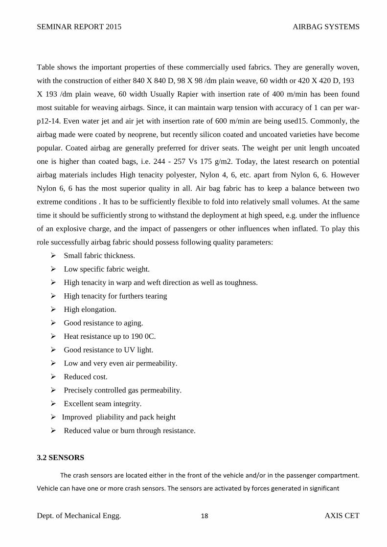
Table shows the important properties of these commercially used fabrics. They are generally woven,
with the construction of either 840 X 840 D, 98 X 98 /dm plain weave, 60 width or 420 X 420 D, 193
X 193 /dm plain weave, 60 width Usually Rapier with insertion rate of 400 m/min has been found
most suitable for weaving airbags. Since, it can maintain warp tension with accuracy of 1 can per war-
p12-14. Even water jet and air jet with insertion rate of 600 m/min are being used15. Commonly, the
airbag made were coated by neoprene, but recently silicon coated and uncoated varieties have become
popular. Coated airbag are generally preferred for driver seats. The weight per unit length uncoated
one is higher than coated bags, i.e. 244 - 257 Vs 175 g/m2. Today, the latest research on potential
airbag materials includes High tenacity polyester, Nylon 4, 6, etc. apart from Nylon 6, 6. However
Nylon 6, 6 has the most superior quality in all. Air bag fabric has to keep a balance between two
extreme conditions . It has to be sufficiently flexible to fold into relatively small volumes. At the same
time it should be sufficiently strong to withstand the deployment at high speed, e.g. under the influence
of an explosive charge, and the impact of passengers or other influences when inflated. To play this
role successfully airbag fabric should possess following quality parameters:
Small fabric thickness.
Low specific fabric weight.
High tenacity in warp and weft direction as well as toughness.
High tenacity for furthers tearing
High elongation.
Good resistance to aging.
Heat resistance up to 190 0C.
Good resistance to UV light.
Low and very even air permeability.
Reduced cost.
Precisely controlled gas permeability.
Excellent seam integrity.
Improved pliability and pack height
Reduced value or burn through resistance.
3.2 SENSORS
The crash sensors are located either in the front of the vehicle and/or in the passenger compartment.
Vehicle can have one or more crash sensors. The sensors are activated by forces generated in significant

SEMINAR REPORT 2015 AIRBAG SYSTEMS
Dept. of Mechanical Engg. 19 AXIS CET
frontal or near-frontal crashes only and not during sudden braking or while driving on rough or uneven
pavement. By function, there are 2 types. Impact sensors and Safing sensors. The forward sensors are located
in various locations forward of the passenger compartment. Some are located inside the fenders, some
are on the cowl, some are attached to the core support in front of the radiator. Rear sensors are also
known as safing sensors as their function is to determine that a crash has occurred. Rear safing sensors
are located in various locations in the passenger compartment depending on the manufacturer. Some
are integrated with the Control/Diagnostic Module. The rear safing sensor must close before the
forward sensors to avoid airbag deployment in cases where the impact is not severe enough to cause
deployment. When the vehicle is parked with the ignition off deployment is very unlikely because
there is no power to the circuits for deployment. Airbag impact sensors, sometimes colloquially called
crash sensors, are important safety features for your vehicle. These sensors, located throughout your
vehicle, detect a collision and trigger the airbags to go off. They are usually found at the front of the
vehicle, behind the front fender, to detect a frontal impact, and in the side columns to detect a side
impact. The exact number and location of airbag sensors you have will vary from one model to
another, but those are the most frequently used locations.
3.2.1 Mass type sensor
An impact sensor in fig no:3.3 is normally fitted to the front of the vehicle as this is where a
collision is likely to occur. The sensor is positioned inside the engine and a similar safety sensor is
located inside the passenger zone to the vehicle. This safety sensor is required to measure the intensity
of the collision to determine whether the impact is over a certain threshold to justify release of an
airbag. Both types of sensors (termed inertia sensors) work on the principle of detecting a decrease in
acceleration of a moving vehicle and generate an electrical impulse. Figure is a schematic diagram of
an inertial sensor
Fig no: 3.3 Mass type sensor

SEMINAR REPORT 2015 AIRBAG SYSTEMS
Dept. of Mechanical Engg. 20 AXIS CET
3.2.2 Roller-type sensor
The roller-type sensor in fig no:3.4 involves a weight connected to a coil spring component.
Like the mass-type sensor, during impact with an oncoming vehicle, the metal weight is forced
forward which alters the tension on the coil spring to manipulate the electrical circuit that closes off
the sensor contact. It is important to note that the impact and safety sensors must activate and close off
at the same time to allow for deployment of the airbag
Fig no: 3.4 Roller-type sensor
3.3 AIRBAG CONTROL UNIT
Fig no: 3.5 Airbag control unit

SEMINAR REPORT 2015 AIRBAG SYSTEMS
Dept. of Mechanical Engg. 21 AXIS CET
The ECU in fig no: 3.5 is the main controlling unit or the brain of the entire passenger safety
system. The ECU not only sends the firing signal to all the air bags, but in the case of a smart air bag
system, it controls the force at which some of those air bags are deployed. These control units are part
of more advanced smart system that can sense whether the front passenger seat is empty, and if so, will
keep the passenger air bag from deploying. The ECU also sends the signal to seat belt pretension
devices and the rollover protection bars in convertibles. The control unit is constantly receiving
sensory input from sensors mounted around the vehicle and makes the necessary calculations to allow
it to deploy the appropriate safety systems. The ECU is typically mounted in the centre of the vehicle
in an area that provides the best protection. Some of the first generation units had capacitors that could
take approximately 20 – 30 minutes for the power to drain after the 12 volt battery was disconnected.
Today’s vehicles, however, have capacitors that drain within seconds. Care must still be taken,
however, during extrication operations to ensure that the ECU is not damaged; this could inadvertently
cause the ECU to deploy an air bag. An even more advanced system senses the weight of the front seat
passenger and can either deploy the air bag with more or less force, depending on the passenger’s
weight. One of the later amendments to the Federal Motor Vehicle Safety Standard 208 requires that
all vehicles manufactured after 2007 are required to be equipped with this type of system. The purpose
of this type of system is to perform one of two functions, depending on the vehicle: keep the front
passenger air bag from deploying if unoccupied, or sense the weight of the occupant in the front seat
and deploy the air bag with less force if the passenger is smaller or with greater force for a larger
person. Some systems are very simple and only sense the presence of a person on the seat, others can
differentiate between a child, small adult or large adult. This type of system, called an Occupant
Classification System or smart system, uses sensors in the seat along with dual stage or de-powered
frontal air bags. This smart system can also sense the severity of the crash using accelerometers, wheel
speed indicators, brake pressure sensors and impact sensors in the vehicles to deploy the air bags with
the appropriate force. Dual stage air bags are equipped two individual inflator units that can be
deployed individually or both at the same time. If the ECU determines that the occupant is a heavier
person or that the crash meets the criteria for a severe crash, both inflator units will fire. If the
occupant is a smaller person or the crash is less severe, it only ignites one of the inflator units, leaving
the second inflator unit un-deployed and loaded.
The danger with this type of system is that if only one of the frontal air bag inflator units has
been deployed, rescuers can falsely assume that that both air bags are no longer a threat. The fact is,
we can have an inflator that is still loaded and ready to deploy the air bag. The typical extrication
scenario has one of the two front seats empty. A rescuer, seeing a deployed air bag, thinks that the

SEMINAR REPORT 2015 AIRBAG SYSTEMS
Dept. of Mechanical Engg. 22 AXIS CET
vehicle is safe and enters the vehicle. The rescuer then places his or her knee on the unoccupied seat.
Now the ECU senses the rescuer’s weight and arms the second un-deployed inflator. The air bag, even
though it has already deployed, is now ready to deploy for a second time into the unsuspecting rescuer.
For this reason, it is especially important to disable the entire system by disconnecting the 12 volt
battery. Even if rescuers are able to disable the system, we must make every effort to keep ourselves
and any patients out of all air bag deployment zones.
Upon signal of a collision, the controller interprets the electrical input and measures the level of collision
to determine release of an airbag. In the event of one impact sensor and safety sensor being closed, an
electrical current is transmitted to an airbag module which contains the airbag and inflator assembly.
Activation of the airbag results in an ignition that produces an electrical transmission between a pair of metal
pins. The electrical arc created between both pins activates a propellant (made up of sodium azide) that starts
to burn and give off nitrogen gas, and it is this gas that starts to fill the airbag. The Volvo V40 model takes
airbag technology to a new level by deploying a pedestrian airbag upon impact on the bumper to this car.
Similar airbag control units currently on the market include a model introduced by TRW. This integrated
control module detects vehicle impact by using an occupant dynamic-based algorithm, which meets all North
American and European regulations with a rollover sensor adapting a functional system similar to the type
discussed in this article. The idea of an integrated airbag control unit has many advantages:
Increased sensitivity of the moving vehicle by placing the integrated control module in the
vehicle’s centre of gravity
Integrated crash sensors diversifies the diagnostics on a collision
Increased precision of the integrated sensor technology to allow for better safety
Cost-effective if all crash sensor systems are integrated into one module.

SEMINAR REPORT 2015 AIRBAG SYSTEMS
Dept. of Mechanical Engg. 23 AXIS CET
CHAPTER 4
WORKING
The first stage of the airbag deployment is the accident itself. The collision, be it frontal or
lateral, activates an array of sensors in the vehicle, including accelerometers, impact sensors, side
pressure sensors, brake pressure sensors, and seat occupancy sensors. All these sensors are in intimate
connection with the ACU (Airbag Control Unit). The unit decides if and how to deploy the airbags.
When the ACU detects that the deployment threshold has been reached, it initiates the inflation stage.
As the compressed air system would have been impractical and quite inefficient, engineers came up
with an idea quite similar to the working principle of the solid rocket booster.
Each airbag incorporates a pyrotechnic device, known as an initiator or electric match,
consisting of an electrical conductor cocooned in combustible material. A current pulse heats up the
conductor, which in turn ignites the combustible material. This igniter triggers the chemical reaction
that actually fills the nylon fabric airbag with gas. The large volume of gas then forces the airbag out
of the steering wheel and/or dashboard at a speed of up to 200 mph or 322 mph, the whole process
taking about 0.04 seconds. Considering that the blink of an eye is approximated at 0.2 seconds, one
could say it's quite a speedy process The last stage of the airbag process is the deflation, which occurs
almost immediately after the inflation is completed. The gas escapes through special vents. They also
prevent the occupants from suffering major impact injuries. Another effect of the deflation is the
release of dust-like particles, mostly cornstarch and talcum powder that are used to lubricate the
airbag. Small amount of Sodium hydroxide may initially be present. This chemical can cause minor
irritation to the eyes and/or open wounds; however, with exposure to air, it quickly turns into Sodium
bicarbonate (common baking soda). Depending on the type of air bag system, potassium chloride (a
table salt substitute) may also be present. Initially, the chemicals used in airbags were a major health
concern, but present systems will only produce a mild irritation of the throat and eyes for most people,
as an outcome of dust released. Generally, these minor irritations continue up to the time occupant
remains in the vehicle with the windows closed and no ventilation. Once deployed, the air bag cannot
be reused and should be replaced by an authorized service department.
SEMINAR REPORT 2015 AIRBAG SYSTEMS
Dept. of Mechanical Engg. 24 AXIS CET
CHAPTER 5
AIRBAG TYPES
With each new generation of vehicles coming out on the market, rescuers are finding that these
vehicles are being equipped with more airbags. All of these air bags are designed with a specific
purpose and function but when used in conjunction with the other safety systems, increase the
survivability of all occupants involved in a vehicle accident. In this section, we will discuss the
different types of air bags, the intended function and the danger that they present to rescuers.
5.1 FRONTAL AIR BAGS
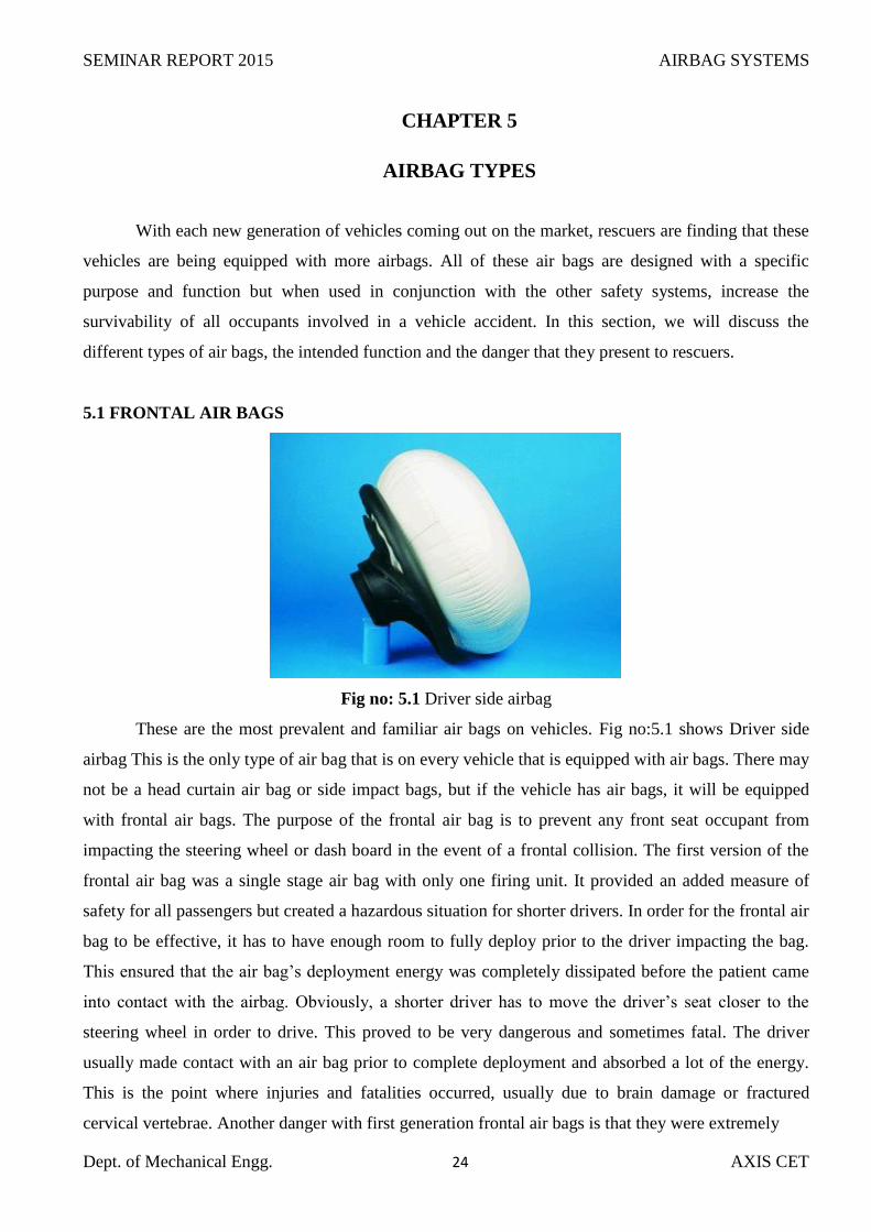
Fig no: 5.1 Driver side airbag
These are the most prevalent and familiar air bags on vehicles. Fig no:5.1 shows Driver side
airbag This is the only type of air bag that is on every vehicle that is equipped with air bags. There may
not be a head curtain air bag or side impact bags, but if the vehicle has air bags, it will be equipped
with frontal air bags. The purpose of the frontal air bag is to prevent any front seat occupant from
impacting the steering wheel or dash board in the event of a frontal collision. The first version of the
frontal air bag was a single stage air bag with only one firing unit. It provided an added measure of
safety for all passengers but created a hazardous situation for shorter drivers. In order for the frontal air
bag to be effective, it has to have enough room to fully deploy prior to the driver impacting the bag.
This ensured that the air bag’s deployment energy was completely dissipated before the patient came
into contact with the airbag. Obviously, a shorter driver has to move the driver’s seat closer to the
steering wheel in order to drive. This proved to be very dangerous and sometimes fatal. The driver
usually made contact with an air bag prior to complete deployment and absorbed a lot of the energy.
This is the point where injuries and fatalities occurred, usually due to brain damage or fractured
cervical vertebrae. Another danger with first generation frontal air bags is that they were extremely
SEMINAR REPORT 2015 AIRBAG SYSTEMS
Dept. of Mechanical Engg. 25 AXIS CET
unreliable. That, coupled with the fact that some did not have any labelling or identification gave Resc-
uers the idea that these airbags were not present. If the 12 volt battery was not disconnected, the
system remained armed. To combat these hazards, an amendment to FMVSS 208 mandated that
vehicles manufactured in 2007 and later be equipped with an Occupant Classification System to work
in conjunction with dual stage or de-powered frontal air bags, as discussed before in the Electrical
Control Unit section. Some older model vehicles were equipped with this system long before the
standard dictated. These air bags, however, are difficult if not impossible to differentiate from single
stage air bags. The rescuer will not know whether the deployed frontal air bag is a single or dual stage
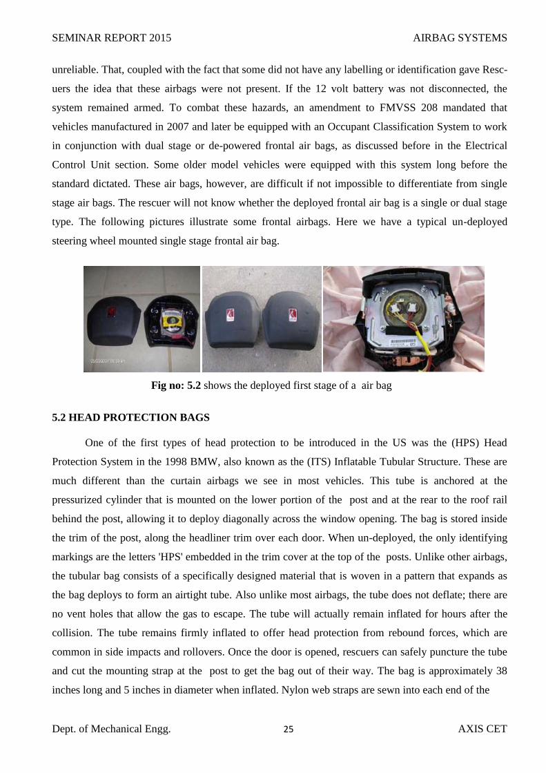
type. The following pictures illustrate some frontal airbags. Here we have a typical un-deployed
steering wheel mounted single stage frontal air bag.
Fig no: 5.2 shows the deployed first stage of a air bag
5.2 HEAD PROTECTION BAGS
One of the first types of head protection to be introduced in the US was the (HPS) Head
Protection System in the 1998 BMW, also known as the (ITS) Inflatable Tubular Structure. These are
much different than the curtain airbags we see in most vehicles. This tube is anchored at the
pressurized cylinder that is mounted on the lower portion of the post and at the rear to the roof rail
behind the post, allowing it to deploy diagonally across the window opening. The bag is stored inside
the trim of the post, along the headliner trim over each door. When un-deployed, the only identifying
markings are the letters 'HPS' embedded in the trim cover at the top of the posts. Unlike other airbags,
the tubular bag consists of a specifically designed material that is woven in a pattern that expands as
the bag deploys to form an airtight tube. Also unlike most airbags, the tube does not deflate; there are
no vent holes that allow the gas to escape. The tube will actually remain inflated for hours after the
collision. The tube remains firmly inflated to offer head protection from rebound forces, which are
common in side impacts and rollovers. Once the door is opened, rescuers can safely puncture the tube
and cut the mounting strap at the post to get the bag out of their way. The bag is approximately 38
inches long and 5 inches in diameter when inflated. Nylon web straps are sewn into each end of the

SEMINAR REPORT 2015 AIRBAG SYSTEMS
Dept. of Mechanical Engg. 26 AXIS CET
Fig 5.3 Head protection airbags
bag to attach it to the vehicle. Like all side impact airbags these cannot deploy a second time. If the
tube is not deployed rescuers must not only stay out of the deployment zone of the tube, but the whole
door area. These tubes are always used in conjunction with a torso type door or seat mounted airbag.
The gas inflator is located at the front end of the system. The canister which is filled with nitrogen,
argon or other inert gas is mounted in the dash at the lower pillar area. These systems will deploy if the
sensor experiences an impact of about 12 mph or above. As stated before the cylinder of a tube can
always be found in the lower portion of the post. This location is in close proximity to where we will
make relief cuts for the different dash displacement evolutions. It is imperative that we make sure to
peel all the plastic from this area to ensure that we do not cut through these cylinders.
5.2.1 Side curtain airbags
The two most commonly used curtain airbags are the front window type and the full length
type. The front window curtain usually extends from the post to post and extends down from the roof
to about the top of the door panel .The full length curtain usually extends from just behind the A post
to post and extends from the roof to the top of the door panel also. Like the head protection tube, both
of these are hidden behind the trim panels and head liner, when undeployed they can only be detected
by small emblems embedded in the trim panels. Rescuers must be aware that these emblems only
indicate the presence of a head curtain bag, not the location. These bags are deployed by small stored
gas inflators that can be located at the front, centre, rear, or anywhere along the support system. They
are found in the post, along the roof rails, in the posts and some even over the rear glass. It is
extremely important that these inflators be visually located before any extrication procedures begin.
Unlike the solid propellant gas canister built into the passenger’s frontal airbag, these inflators have no
protection around them; they are simply a long thin tube that is filled with a compressed inert gas.

SEMINAR REPORT 2015 AIRBAG SYSTEMS
Dept. of Mechanical Engg. 27 AXIS CET
Fig no: 5.4 Side curtain airbags
Some vehicles, such as the Volvo XC90, Infinity QSX, Nissan Pathfinder, Armada and Quest
minivan, and Ford Excursion have head curtains in two sections, requiring two cylinders to deploy the
curtain. Again, it becomes extremely important to expose as much of the plastic as possible prior to
beginning any evolutions.
5.3 SIDE IMPACT AIRBAGS
Fig no: 5.5 Side impact airbags
Side impact air bags fig no:5.5 are designed to protect a passenger’s head and thorax with
some style of bags or just the thorax with another type of bag. Some of these bags are designed to help
keep an occupant from being ejected from a vehicle in a roll over. Like the frontal airbags; side impact
airbags must have a crash sensor to recognize that a crash has occurred. These sensors are usually
mounted in the frond door, the post, or most are located inside the rocker panel just below the post.
The cylinders for these bags can be mounted in the post and also underneath the folded air bag in the
seat back. Some older vehicles used the same chemical propellant, sodium azide, used in frontal air
bags. The air bags can be mounted in one of two locations: the door or the out board side of the seat

SEMINAR REPORT 2015 AIRBAG SYSTEMS
Dept. of Mechanical Engg. 28 AXIS CET
back. The door mounted bags can either mounted on the inside of the door and deploy from a blow out
panel. Some newer door mounted bags pop up, like a toaster, from the top of the door. The 2010 Volvo
C70c1920c on vertible has an air bag that extends the entire length of the passenger compartment,
from the post to the rear of the passenger compartment. This bag is extremely rigid so that it can
provide the necessary head protection, even without a roof. These bags obviously present a danger to
rescuers who are leaning over the door of a car that has not had the battery disconnected. Side impact
bags that are mounted in the seat are usually powered by high pressure cylinders. Some older cars,
however, still use chemical propellants. As stated before the cylinders can be mounted in the posts of
the vehicle or in that actual seat back itself, usually under the folded air bag.
The seat mounted bag is usually placed under the seat fabric in the out board side of the seat. It
can either come out of a blow out panel or from a pre stressed seam in the fabric that is designed to
tear open on air bag deployment. The danger with this type of air bag is its deployment path. The
normal path is to first deploy outwards before it goes forward. The bag uses the closed door to rebound
inward changing the direction of the bag. If a door is opened or has been removed, a rescuer standing
in the door way may think that he is out of the deployment zone, but due to the bags deployment path,
might be placing him or herself in danger.
5.4 OCCUPANT POSITIONING AIR BAGS
Occupant positioning air bags are different bags placed throughout the vehicle that work
together, along with the seat belt and pretensioner, and have the sole purpose of keeping front seat
occupants from sliding out of the seat in a front end collision. In this type of collision, a person in the
front seat usually slides out of their seat and is thrown under the dash if this system is not in place.
This is known as submarine and usually meant significant injury or death to the occupant. Some
vehicles may have some or all of these types of bags and some vehicles may not be equipped with any
at all. All of these bags present their own unique dangers that we will now discuss.
5.4.1 Knee bags or bolsters
These bags fig no:5.6 deploy exactly where their name suggests. They are usually placed under
the steering column and under the passenger side dash board. They function not only as part of the
Occupant Positioning System, they also reduce the severe knee and hip injuries that normally occur
During a front end collision. These bags, as well as the others we will discuss, work in conjunction to
keep the occupant in their seat. There are two basic types of bags: the knee bag and the knee bolster.
Both serve the same purpose. The knee bag is just a simple air bag that deploys outward from the dash
toward the front edge of the seat. These bags are usually powered by the same firing units and the

SEMINAR REPORT 2015 AIRBAG SYSTEMS
Dept. of Mechanical Engg. 29 AXIS CET
propellants (sodium-azide) as the frontal air bags and are usually identified on the blow out panel. The
picture shows an identification stamp. On the right is a picture of a deployed knee bag.
Fig no: 5.6 left shows an identification stamp. On the right is a picture of a deployed knee bag.
5.5 CARPET BAGS
Carpet bags in fig no:5.7are mounted in the floor board of the vehicle and use the same sensors
as frontal air bags. These air bags deploy using a pressurized gas cylinder that is usually mounted over
the centre tunnel. The purpose of this bag is to push the occupant’s feet up, thereby slightly changing
the angle of the occupant’s legs. This slight change of angle in the legs will help keep the patient from
sliding out of the seat and under the dash. The danger comes more from where the pressurized cylinder
is mounted. Rescuers may not expect that cylinder is in the centre tunnel and cut through it or weaken
it during operations
.
Fig no: 5.7 Picture of a deployed carpet bag
5.6 ANTI-SLIDE SEAT BAGS
The anti-slide seat bag in fig no:5.8 is one of newest bags to be installed in vehicles. It is not
actually a bag, but instead a thin metal envelop structure that is mounted under the foam cushion of the

SEMINAR REPORT 2015 AIRBAG SYSTEMS
Dept. of Mechanical Engg. 30 AXIS CET
seat. The operating principle of this bag is similar to an airbag except that the bag never comes in
contact with the occupant. The bag operates in two stages upon receiving the firing signal from the
ECU: First, a gas generator inflates the metallic envelope which pushes the foam up in the front edge
of the seat. This action pushes the occupant back and against the seat back. Second, a deflation
controller beneath the module slowly deflates the envelope and causes the metal envelope to form to
the shape of the pelvis. This forms a pocket in the seat to hold the occupant in position, forming a
protective shield around the pelvis. It also assists the carpet bag in lifting the weight of the occupants
legs preventing the downward force of the feet pushing into the floor. With this bag, the obvious
danger occurs when a rescuer places his or her knee on a seat with an un-deployed bag.
Fig no: 5.8 Anti-slide Seat bag
5.7 MISCELLANEOUS AIRBAGS
In this section in fig no: 5.9 we will illustrate what the rescuer has in store for him as far as the
future of the air bag. The direction of seat belt technology shows us that the possibility of air bags and
their locations is limitless.
Fig no: 5.9 Air bag in the head rest of the rear seat in a passenger car.

SEMINAR REPORT 2015 AIRBAG SYSTEMS
Dept. of Mechanical Engg. 31 AXIS CET
Fig no: 5.10 Air bag installed in the seat belt.
Not all air bags will be inside the patient compartment. Soon, rescuers will be faced with hood, front
bumper and/or windshield air bags.
Fig no: 5.11 Pedestrians protection airbags
The Jaguar XK fig no:5.11 has 2 airbags under the hood that help to protect pedestrians by cushioning
the hood and decreasing the impact force into the windshield. Ford will soon be unveiling a bumper
and windshield air bag that is designed to protect the pedestrian from impacting the bumper and hood.
The windshield bag will decrease the force of impact with the windshield while assisting in vaulting
the patient over the windshield and roof of the car.

SEMINAR REPORT 2015 AIRBAG SYSTEMS
Dept. of Mechanical Engg. 32 AXIS CET
Fig no: 5.12 This air bag to deflect the path of the rider up and
over the impacted vehicle
Air bags will not only be seen in cars, they will also be installed on motorcycles as well. This air bag is
designed in fig no:5.12 to deflect the path of the rider up and over the impacted vehicle. Before, the
rider would fly directly into the vehicle causing fatal head and neck injuries
Fig no: 5.13 Airbag vest is available to motorcycle riders

SEMINAR REPORT 2015 AIRBAG SYSTEMS
Dept. of Mechanical Engg. 33 AXIS CET
An airbag vest in fig no:5.13 is available to motorcycle riders to give protection to the head and upper
torso in a crash. The vest is only effective if the rider is wearing a helmet. As we have clearly seen, air
bags present a very real danger to both rescuers and patients during extrication operations, regardless if
they have deployed. The most important thing to take away from this is to always operate as if you are
surrounded by live and loaded air bags. Vehicle manufacturers have installed safety devices in an
attempt to prevent accidental deployment but we should not and cannot depend on those devices to be
operational after an accident. Even if the vehicle has been stabilized and the battery has been
disconnected, you must protect yourself, your crew and your patient from the possibility of being
impacted by an air bag.

SEMINAR REPORT 2015 AIRBAG SYSTEMS
Dept. of Mechanical Engg. 34 AXIS CET
CHAPTER 6
AIRBAG RISKS
6.1 AIR BAG CONTACT INJURIES
Air bags must inflate very rapidly to be effective, and therefore come out of the steering wheel
hub or instrumental panel with considerable force, generally at a speed over 100 mph. Due to this very
high initial force, contact with a deploying air bag may cause injury. Properly restraint occupant along
with applied due seat belt receives very minor abrasion or burns. However, very serious or fatal
injuries can occur when someone is very close to, or in direct contact with an air bag module when the
air bag deploys. Even never attach objects to an air bag module or place loose objects on or near an air
bag module, since they can be propelled with great force by a deploying air bag, potentially cause
serious or fatal injuries. Thus safety restraint system must be utilized with due care and regulation to
get best results. An unrestrained or improperly restraint occupant can be seriously injured or killed by
a deploying air bag. The National Highway Traffic Safety Administration (NHTSA) recommended
certain rules for the safety of occupant and passengers.
They are as follows:
Never put a rear-facing infant restraint in the front seat of a vehicle with a front passenger air
bag.
Children of age 12 and under should be properly restrained in a rear seat.
Driver should sit with at least 10 inches between the centre of their chest bone and the steering
wheel.
Always apply seat belt, it retain occupant and passenger rightly positioned and minimizes risk
of serious injuries.

SEMINAR REPORT 2015 AIRBAG SYSTEMS
Dept. of Mechanical Engg. 35 AXIS CET
CHAPTER 7
CONCLUSION
The air bags are of greater importance in today’s vehicles since safety of human life is of prior
importance. Since the count of automobiles is increasing tremendously on our roads, the probability of
accidents is also more. So far a safe riding and for saving the precious life the safety bags must be
implemented. Today it is the privilege of the high class people who own high priced cars. Let’s hope
every automobile manufacturer implement the same since safety for life is inevitable. The number of
persons killed or injured in traffic has dropped continuously since the development of air bag system.
Over the time, the development of seat belt becomes an indisputable matter of course. Today, the 3-
point automatic seat belt, seat belt tensioner and airbag constitute a carefully matched passenger
protection system. Implementation of these safety restraint systems with due care and regulation can
further drop the fatality rate and serious injuries at the time of road accidents

SEMINAR REPORT 2015 AIRBAG SYSTEMS
Dept. of Mechanical Engg. XXXVI
AXIS CET
CHAPTER 8
REFERANCE
[1] Panchal. M, Dayaramani. A ,Project done by DKTE students,2004, online launched on,
http://www.textilepapers.tripod.com , vol 3.
[2] Goltner .W , Fabric for airbag US5236775 A patent published in Aug 17,Gogle patent ,
1993 ,vol 1
[3] Khan. M. S, project done by DKTE students,Textile 2001 learner– Air-bag for
automobiles, http://www.textilelearner.blogspot.com , vol 1
[4] Dupont , Sun. J, Barnes J. A, Airbag End-Use Technology,1999, Marerial selection for
Air-bags , vol 7
[5] C. Bastien, M. V. Blundell, D. Stubbs, J. Christensen, J. Hoffmann, M. Reisinger, R. Van
Der Made, Correlation of Airbag Fabric Material Mechanical Failure Characteristic for Out
of Position Applications, 2010, proceedings of isma 2010 including usd vol 1