Embed Size (px)
Citation preview
International Communications in Heat and Mass Transfer 37 (2010) 1366–1375
Contents lists available at ScienceDirect
International Communications in Heat and Mass Transfer
j ourna l homepage: www.e lsev ie r.com/ locate / ichmt
CFD modeling of heat transfer and fluid flow inside a pent-roof type combustionchamber using dynamic model☆
Yasin Varol a,⁎, Hakan F. Oztop a,1, Mujdat Firat a, Ahmet Koca b
a Department of Mechanical Education, Firat University, 23119 Elazig, Turkeyb Technical Vocational School, Firat University, 23119 Elazig, Turkey
☆ Communicated by W.J. Minkowycz.⁎ Corresponding author.
E-mail address: [email protected] (Y. Varol).1 Visiting Professor, King Saud University, Departme
Saudi Arabia.
0735-1933/$ – see front matter © 2010 Elsevier Ltd. Aldoi:10.1016/j.icheatmasstransfer.2010.07.003
a b s t r a c t
a r t i c l e i n f oAvailable online 9 August 2010
Keywords:Internal combustion engineCFDHeat transferCombustion chamber
A numerical work has been performed to analyze the heat transfer and fluid flow in a pent-roof typecombustion chamber. Dynamic mesh model was used to simulation piston intake stroke. Revolution ofpiston (1000≤n≤5000) is the main governing parameter on heat and fluid flow. k–ε turbulence model wasused to predict the flow in the cylinder of a non-compressing fluid. They were solved with finite volumemethod and FLUENT 12.0 commercial code. Velocity profiles, temperature distribution, pressuredistribution and velocity vectors are presented. It is found that the inclined surface of pent-roof type ofcombustion chamber reduces the swirl effect and it can be a control parameter for heat and fluid flow.
nt of Mechanical Engineering,
l rights reserved.
© 2010 Elsevier Ltd. All rights reserved.
1. Introduction
Fluid flow, heat transfer and combustion in an internal combustionengine are one of the important problems in thermofluid mechanics.In recent years, Computational Fluid Dynamics (CFD) techniques areused due to developing of numerical techniques and computercapabilities. The CFD is an indispensable tool for engine developmentwith the increasing of computer capabilities. As well known that thefluid motion inside a cylinder is turbulent, unsteady, cyclic and non-stationary both spatially and temporally [1]. The fluidmotion and heattransfer inside the cylinder of an internal combustion engine isstrongly related with the performance of the engine efficiency. Thisphenomenon is addressed by different researches as given in Ref.[2,3].
There are two types of internal combustion engine; one is sparkignition (SI) engines, where the fuel is ignited by a spark, the other iscompression ignition (CI) engines, where the rise in temperature andpressure during compression is sufficient to cause spontaneousignition of the fuel. Analysis of flow and heat transfer in-cylinder isperformed with two different methods as CFD and visualization usingLDV [4], PIV etc. [5,6]. However, there have been numerouscomputational techniques on this. In this field, there are many
computational commercial (FLUENT, KIVA, VECTICS, STAR-CD and soon) or personal codes using finite volume [7], finite element methods[8] C++ or FORTRAN. In this context, Akar [9] studied the flowcharacteristics of some engine models in two-dimensional, three-dimensional and dynamic model using FLUENT CFD solver. Numericalmodels were carried out at various valve gaps for all models. Theyshowed that the flow structure is highly affected by the valve positionand cylinder length. Payri et al. [10] studied the three-dimensionalflow calculations of the intake and compression stroke of a four-valvedirect-injection Diesel engine with different combustion chamber.Wu and Perng [11] studied the LES analysis of turbulent flow and heattransfer in motored engines with different subgrid-scale models. Theytested the flow during the compression–expansion strokes in twotypes of engine configuration under realistic engine conditions. Asindicated by Hong and Tarng [12] that the in-cylinder fluid motion isso complex that it is of non-stationary turbulence. Thus, it is verydifficult to develop a model for turbulence in-cylinder. Moureau andAngelberger [13] studied the cyclic variability in IC engines using 3DCFD code. In their work, the Smagorinsky model was used in LESsimulations. Bilgin [14] made a numerical simulation of the cold flowin an axisymmetric non-compressing engine-like geometry. Hecompared the obtained results with the measurements of literature.Milton et al. [15] investigated the two-phase fuel/air flow through aninternal combustion engine inlet valve both experimentally andnumerically. They indicated that simulation of the process for the gas-phase flow using the proprietary code, FLUENT gives good agreementwith experiment. More recently, Song et al. [16] analyzed the three-dimensional flow calculations of the in-cylinder flow for a direct-injection Diesel engine for different combustion chambers. Theyshowed that the geometries of the piston have a significant effect on
Nomenclature
e internal energy per unit mass, J/kgGb the generation of turbulence kinetic energy due to
buoyancyGk represents the generation of turbulence kinetic energy
due to the mean velocity gradientsk thermal conductivity, W/mKn engine speed, rpmp pressure, PaT temperature, Kt time, su, v, w velocity magnitudes in direction −x,−y,−z, m/sV volume, m3
Vc combustion chamber volume, m3
Greek symbolsθ crank angle� turbulent dissipation rate, m2/s3
μ dynamic viscosity, Pa/sμt turbulence viscosityρ fluid density, kg/m3
σk the turbulent Prandtl numbers for kσ� the turbulent Prandtl numbers for �
1367Y. Varol et al. / International Communications in Heat and Mass Transfer 37 (2010) 1366–1375
the distribution of the cross section-averaged swirl ratio. Thetangential velocity profiles at the cross sections are highly nonlinear,and the rigid body rotation assumption is less admissible. Ceper [17]studied the combustion and emission performance characteristics ofdifferent percentage ratios of hydrogen–methane gas mixturesexperimentally and numerically. 100% CH4, 10% H2-90% CH4, 20%H2-80% CH4 and 30% H2-70% CH4 gas mixtures were investigated at2000 rpm engine speeds and excess air ratios on a model, which isdeveloped based on real engine diameters used in her numericalstudy. In-cylinder pressure and temperature variations were givenbased on crank angles. She found that numerical study were foundwell-matched with experimental results.
The main purpose of the present study is to investigate the heattransfer and fluid flow in a pent-roof type combustion chamber andthe effects of the combustion chamber shape on the flow duringintake stroke. The engine studied in this paper is a single-cylinderspark-ignition gasoline engine with one intake port of the cylinder.The study shows how flow acts inside of whole intake cycle and itclarifies some places in which designer should consider somegeometrical innovations.
2. Definition of considered model
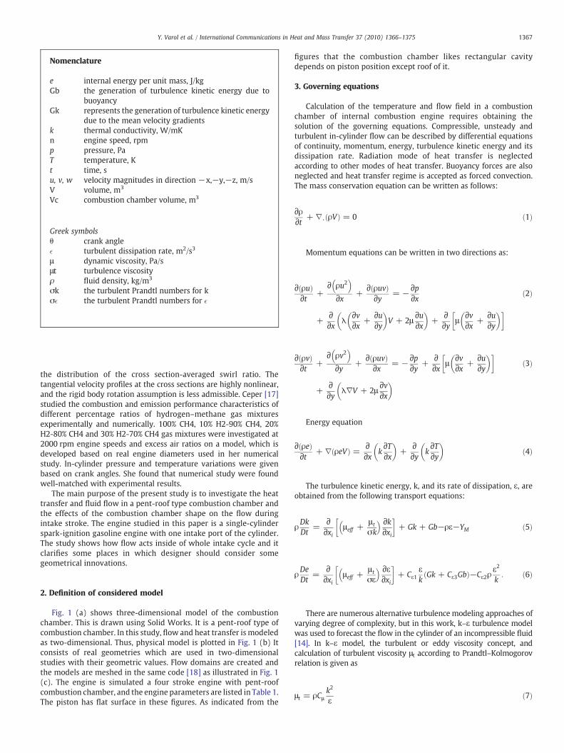
Fig. 1 (a) shows three-dimensional model of the combustionchamber. This is drawn using Solid Works. It is a pent-roof type ofcombustion chamber. In this study, flow and heat transfer is modeledas two-dimensional. Thus, physical model is plotted in Fig. 1 (b) Itconsists of real geometries which are used in two-dimensionalstudies with their geometric values. Flow domains are created andthe models are meshed in the same code [18] as illustrated in Fig. 1(c). The engine is simulated a four stroke engine with pent-roofcombustion chamber, and the engine parameters are listed in Table 1.The piston has flat surface in these figures. As indicated from the
figures that the combustion chamber likes rectangular cavitydepends on piston position except roof of it.
3. Governing equations
Calculation of the temperature and flow field in a combustionchamber of internal combustion engine requires obtaining thesolution of the governing equations. Compressible, unsteady andturbulent in-cylinder flow can be described by differential equationsof continuity, momentum, energy, turbulence kinetic energy and itsdissipation rate. Radiation mode of heat transfer is neglectedaccording to other modes of heat transfer. Buoyancy forces are alsoneglected and heat transfer regime is accepted as forced convection.The mass conservation equation can be written as follows:
∂ρ∂t + ∇⋅ ρVð Þ = 0 ð1Þ
Momentum equations can be written in two directions as:
∂ ρuð Þ∂t +
∂ ρu2� �∂x +
∂ ρuvð Þ∂y = −∂p
∂x
+∂∂x λ
∂v∂x +
∂u∂y
� �V + 2μ
∂u∂x
� �+
∂∂y μ
∂v∂x +
∂u∂y
� �� �ð2Þ
∂ ρvð Þ∂t +
∂ ρv2� �∂y +
∂ ρuvð Þ∂x = −∂p
∂y +∂∂x μ
∂v∂x +
∂u∂y
� �� �
+∂∂y λ∇V + 2μ
∂v∂x
� �ð3Þ
Energy equation
∂ ρeð Þ∂t + ∇ ρeVð Þ = ∂
∂x k∂T∂x
� �+
∂∂y k
∂T∂y
� �ð4Þ
The turbulence kinetic energy, k, and its rate of dissipation, ε, areobtained from the following transport equations:
ρDkDt
=∂∂xi
μeff +μ t
σk
� � ∂k∂xi
� �+ Gk + Gb−ρε−YM ð5Þ
ρDeDt
=∂∂xi
μeff +μ t
σε
� � ∂ε∂xi
� �+ Cε1
εk
Gk + Cε3Gbð Þ−Cε2ρε2
k: ð6Þ
There are numerous alternative turbulence modeling approaches ofvarying degree of complexity, but in this work, k–ε turbulence modelwas used to forecast the flow in the cylinder of an incompressible fluid[14]. In k–ε model, the turbulent or eddy viscosity concept, andcalculation of turbulent viscosity μt according to Prandtl–Kolmogorovrelation is given as
μt = ρCμk2
εð7Þ
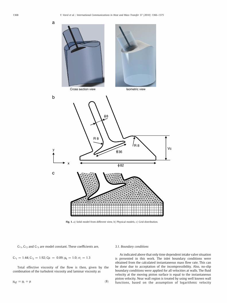
Fig. 1. a) Solid model from different view, b) Physical models, c) Grid distribution.
1368 Y. Varol et al. / International Communications in Heat and Mass Transfer 37 (2010) 1366–1375
C�1, C�2 and C�3 are model constant. These coefficients are,
C�1 = 1:44; C�2 = 1:92; Cμ = 0:09; μk = 1:0; σ� = 1:3
Total effective viscosity of the flow is then, given by thecombination of the turbulent viscosity and laminar viscosity as
μeff = μt + μ ð8Þ
3.1. Boundary conditions
As indicated above that only time dependent intake valve situationis presented in this work. The inlet boundary conditions wereobtained from the calculated instantaneous mass flow rate. This canbe done due to acceptation of the incompressibility. Also, no-slipboundary conditions were applied for all velocities at walls. The fluidvelocity at the moving piston surface is equal to the instantaneouspiston velocity. Near wall region is treated by using well known wallfunctions, based on the assumption of logarithmic velocity

Table 1Engine geometry and parameters.
Bore/mm 82Stroke/mm 90Intake valve angle/deg 22Crank period/deg 720Engine speed/rpm 1000, 3000 and 5000
1369Y. Varol et al. / International Communications in Heat and Mass Transfer 37 (2010) 1366–1375
distribution [19]. Boundary conditions for the considered physicalmodel (Fig. 1) are given as
Inlet temperature, Tinlet=303 KSide temperature of combustion chamber, Tside=493 K
Temperature of piston head, Tpiston=493 K
Inlet velocities are V=14, 33 and 54 m/s for n=1000, 3000 and5000 rpm, respectively.
Velocities at side of cylinder, u=0, v=0
Velocities at piston surface, u=0, v=vpiston
4. Numerical solution
The flow characteristics of engine models are considered as two-dimensional. Dynamic models were investigated numerically bymeans of FLUENT commercial code [18]. It is a well knownComputational Fluid Dynamic program that it is the science of
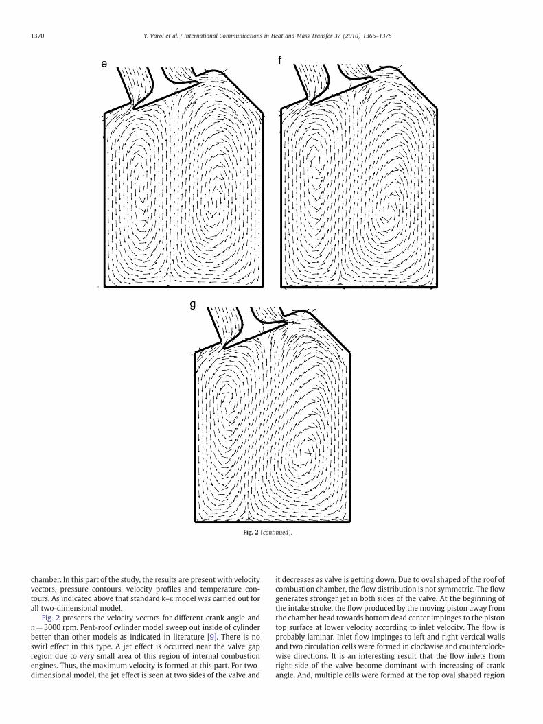
Fig. 2. Velocity vectors for different crank angle at n=3000 rpm, a) θ=3
predicting fluid flow, heat transfer, mass transfer, chemical reactions,and related phenomena by solving governing equations. Thisprogram uses finite volume method in order to solve Navier-stokesand energy equations and it is widely used in the field of internalcombustion engine design. The finite volume method can accom-modate any type of grid. Thus, it is suitable for complex geometries,like present study. The standard k–ε turbulence model was used asengine model. The CFD code is based on the pressure-correction anduses the SIMPLE algorithm of Patankar [20]. The first order upwinddifference scheme (UDS) is used to discretize themomentum, energyand turbulence equations. The dynamic grid approach is used to treatthemoving piston in the computational area. In other words, the gridgeneration approachwas used to treat themoving piston as amovingsolid body in the computational domain without generatingcompletely new grids at each crank angle step [21]. Piston movestowards to the bottom dead center (BDC). The calculations arestarted with a crank angle of top dead center (TDC) and finished at30° after bottom dead center (aBDC) in the compression strokefor a different engine speed as 1000, 3000 and 5000 rpm. The modelstructure is hybrid grid and to setup boundary condition for movingpiston. Total number of computational cells was used about 50,000 atBDC and 10,000 cells at TDC. A typical grid distribution is shown inFig. 2.
5. Results and discussion
A computational study has been performed in this work fordifferent crank angles and revolution of pent-roof combustion
0°, b) θ=60°, c) θ=90°, d) θ=120°, e) θ=150°, f) θ=180°, g) θ=210°.
}
Fig. 2 (continued).
1370 Y. Varol et al. / International Communications in Heat and Mass Transfer 37 (2010) 1366–1375
chamber. In this part of the study, the results are present with velocityvectors, pressure contours, velocity profiles and temperature con-tours. As indicated above that standard k–ε model was carried out forall two-dimensional model.
Fig. 2 presents the velocity vectors for different crank angle andn=3000 rpm. Pent-roof cylinder model sweep out inside of cylinderbetter than other models as indicated in literature [9]. There is noswirl effect in this type. A jet effect is occurred near the valve gapregion due to very small area of this region of internal combustionengines. Thus, the maximum velocity is formed at this part. For two-dimensional model, the jet effect is seen at two sides of the valve and
it decreases as valve is getting down. Due to oval shaped of the roof ofcombustion chamber, the flow distribution is not symmetric. The flowgenerates stronger jet in both sides of the valve. At the beginning ofthe intake stroke, the flow produced by the moving piston away fromthe chamber head towards bottom dead center impinges to the pistontop surface at lower velocity according to inlet velocity. The flow isprobably laminar. Inlet flow impinges to left and right vertical wallsand two circulation cells were formed in clockwise and counterclock-wise directions. It is an interesting result that the flow inlets fromright side of the valve become dominant with increasing of crankangle. And, multiple cells were formed at the top oval shaped region

Fig. 3. Comparison of velocity vectors for different revolutions at θ=90°, a) n=1000 rpm, b) n=5000 rpm.
1371Y. Varol et al. / International Communications in Heat and Mass Transfer 37 (2010) 1366–1375
for higher crank angle. Impinging flow onto piston moves toward tovalve and again impinges to the valve. This is a characteristic flowmotion of a gas engines. For higher crank angles, the combustionchamber looks a cavity. Please note that in case of crank angle of 210°,the pistonmoves toward to TDC. Fig. 3 display the effects of revolution
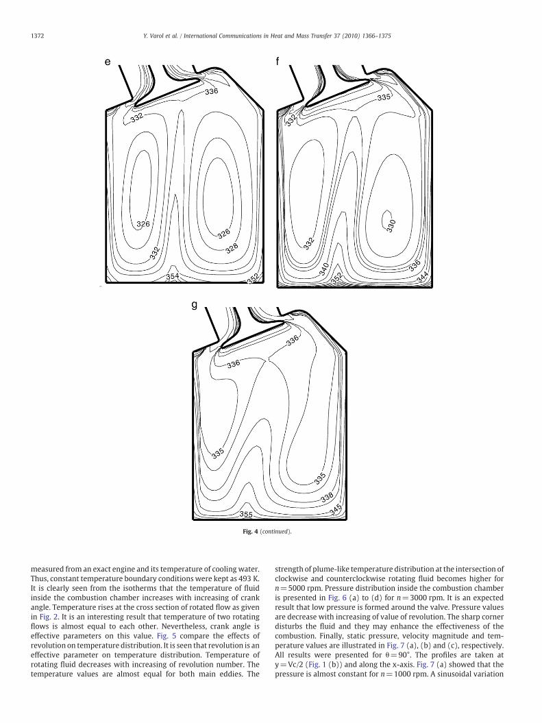
Fig. 4. Isotherms for different crank angle at n=3000 rpm, a) θ=30°, b)
for the same crank angle. Revolution number is not an effectiveparameter on velocity direction. But boundary layer becomes thinnesson top of piston at higher revolution.
Fig. 4 illustrate the isotherms of the same case of Fig. 2. It is noticedthat temperature boundary conditions for combustion chamber was
θ=60°, c) θ=90°, d) θ=120°, e) θ=150°, f) θ=180°, g) θ=210°.
}
Fig. 4 (continued).
1372 Y. Varol et al. / International Communications in Heat and Mass Transfer 37 (2010) 1366–1375
measured from an exact engine and its temperature of cooling water.Thus, constant temperature boundary conditions were kept as 493 K.It is clearly seen from the isotherms that the temperature of fluidinside the combustion chamber increases with increasing of crankangle. Temperature rises at the cross section of rotated flow as givenin Fig. 2. It is an interesting result that temperature of two rotatingflows is almost equal to each other. Nevertheless, crank angle iseffective parameters on this value. Fig. 5 compare the effects ofrevolution on temperature distribution. It is seen that revolution is aneffective parameter on temperature distribution. Temperature ofrotating fluid decreases with increasing of revolution number. Thetemperature values are almost equal for both main eddies. The
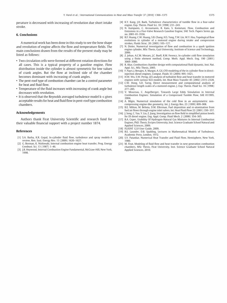
strength of plume-like temperature distribution at the intersection ofclockwise and counterclockwise rotating fluid becomes higher forn=5000 rpm. Pressure distribution inside the combustion chamberis presented in Fig. 6 (a) to (d) for n=3000 rpm. It is an expectedresult that low pressure is formed around the valve. Pressure valuesare decrease with increasing of value of revolution. The sharp cornerdisturbs the fluid and they may enhance the effectiveness of thecombustion. Finally, static pressure, velocity magnitude and tem-perature values are illustrated in Fig. 7 (a), (b) and (c), respectively.All results were presented for θ=90°. The profiles are taken aty=Vc/2 (Fig. 1 (b)) and along the x-axis. Fig. 7 (a) showed that thepressure is almost constant for n=1000 rpm. A sinusoidal variation
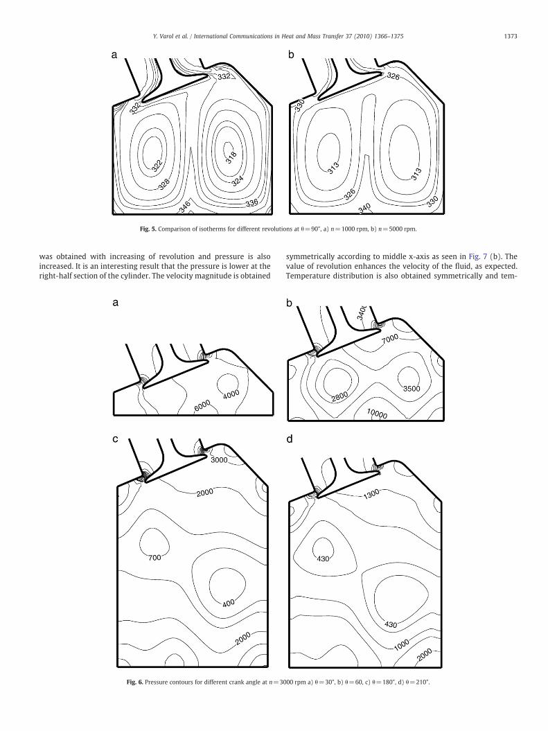
Fig. 5. Comparison of isotherms for different revolutions at θ=90°, a) n=1000 rpm, b) n=5000 rpm.
1373Y. Varol et al. / International Communications in Heat and Mass Transfer 37 (2010) 1366–1375
was obtained with increasing of revolution and pressure is alsoincreased. It is an interesting result that the pressure is lower at theright-half section of the cylinder. The velocity magnitude is obtained
Fig. 6. Pressure contours for different crank angle at n=30
symmetrically according to middle x-axis as seen in Fig. 7 (b). Thevalue of revolution enhances the velocity of the fluid, as expected.Temperature distribution is also obtained symmetrically and tem-
00 rpm a) θ=30°, b) θ=60, c) θ=180°, d) θ=210°.

Fig. 7. a) Static pressure, b) Velocity, c) Temperature for different revolution at θ=90°.
1374 Y. Varol et al. / International Communications in Heat and Mass Transfer 37 (2010) 1366–1375
1375Y. Varol et al. / International Communications in Heat and Mass Transfer 37 (2010) 1366–1375
perature is decreased with increasing of revolution due short intakestroke.
6. Conclusions
A numerical work has been done in this study to see the how shapeand revolution of engine affects the flow and temperature fields. Themain conclusions drawn from the results of the present study may belisted as follows:
• Two circulation cells were formed at different rotation directions forall cases. This is a typical property of a gasoline engine. Flowdistribution inside the cylinder is almost symmetric for low valuesof crank angles. But the flow at inclined side of the chamberbecomes dominant with increasing of crank angles.
• The pent-roof type of combustion chamber can be a control parameterfor heat and fluid flow.
• Temperature of the fluid increases with increasing of crank angle butdecreases with revolution.
• It is observed that the Reynolds averaged turbulencemodel k–ε givesacceptable results for heat andfluidflow inpent-roof type combustionchambers.
Acknowledgements
Authors thank Firat University Scientific and research fund fortheir valuable financial support with a project number 1874.
References
[1] S.A. Basha, K.R. Gopal, In-cylinder fluid flow, turbulence and spray models-Areview, Ren. Sust. Energy Rev. 13 (2009) 1620–1627.
[2] G. Borman, K. Nishiwaki, Internal combustion engine heat transfer, Prog. EnergyCombust. Sci. 13 (1987) 1–46.
[3] J.B. Heywood, Internal Combustion Engine Fundamental, McGraw-Hill, New York,1998.
[4] K.Y. Kang, J.H. Baek, Turbulence characteristics of tumble flow in a four-valveengine, Exp. Therm. Fluid Sci. 18 (1998) 231–243.
[5] N. Kampanis, C. Arcoumanis, R. Kato, S. Kometani, Flow, Combustion andEmissions in a Five-Valve Research Gasoline Engine, SAE Tech. Papers Series pp.no. 2001-01-3556.
[6] R.F. Huang, C.W. Huang, S.B. Chang, H.S. Yang, T.W. Lin, W.Y. Hsu, Topological flowevolutions in cylinder of a motored engine during intake and compressionstrokes, Fluids Struc. 20 (2005) 105–127.
[7] N. Dinler, Numerical investigation of flow and combustion in a spark ignitionengine cylinder, MSc Thesis, Gazi University, Institute of Science and Technology,2006.
[8] Z. Johan, A.C.M. Moraes, J.C. Buell, R.M. Ferencz, In-cylinder cold flow simulationusing a finite element method, Comp. Meth. Appl. Mech. Eng. 190 (2001)3069–3080.
[9] R. Akar, Combustion chamber design with computational fluid dynamic, Inst. Nat.Appl. Sci., MSc Thesis, 2005.
[10] F. Payri, J. Benajes, X. Margot, A. Gil, CFDmodeling of the in-cylinder flow in direct-injection diesel engines, Comput. Fluids 33 (2004) 995–1021.
[11] H.W. Wu, S.W. Perng, LES analysis of turbulent flow and heat transfer in motoredengines with various SGS models, Int. Heat Mass Transfer 45 (2002) 2315–2328.
[12] C.W. Hong, S.D. Tarng, Direct measurement and computational analysis ofturbulence length scales of a motored engine, J. Exp. Therm. Fluid Sci. 16 (1998)277–285.
[13] V. Moureau, C. Angelberger, Towards Large Eddy Simulation in InternalCombustion Engines: Simulation of a Compressed Tumble Flow, SAE 011995,2004.
[14] A. Bilgin, Numerical simulation of the cold flow in an axisymmetric non-compressing engine-like geometry, Int. J. Energy Res. 23 (1999) 899–908.
[15] B.E. Milton, M. Behnia, D.M. Ellerman, Fuel deposition and re-atomisation fromfuel/air flows through engine inlet valves, Int. Heat Fluid Flow 22 (2001) 350–357.
[16] J. Song, C. Yao, Y. Liu, Z. Jiang, Investigation on flow field in simplified piston bowlsfor DI diesel engine, Eng. Appl. Comp. Fluid Mech. 2 (2008) 354–365.
[17] B.A. Ceper, Usability Of Hydrogen-Natural Gas Mixtures In Internal CombustionEngines, PhD. Thesis, Erciyes University, Inst. Science Graduate School Natural andApplied Sciences, 2009.
[18] FLUENT 12.0 User Guide, 2009.[19] B.E. Launder, D.B. Spalding, Lectures in Mathematical Models of Turbulence,
Academic Press, London, 1972.[20] S.V. Patankar, Numerical Heat Transfer and Fluid Flow, Hemisphere, New York,
1980.[21] M. Firat, Modeling of fluid flow and heat transfer in new generation combustion
chambers, MSc Thesis, Firat University, Inst. Science Graduate School NaturalApplied Sciences, 2010.