Embed Size (px)
Citation preview
Emma Yee and Thomas WeyGlenn Research Center, Cleveland, Ohio
Beta Testing of CFD Code for the Analysis of Combustion Systems
NASA/TM—2015-218897
November 2015
https://ntrs.nasa.gov/search.jsp?R=20150023060 2018-07-10T01:01:50+00:00Z

NASA STI Program . . . in Profi le
Since its founding, NASA has been dedicated to the advancement of aeronautics and space science. The NASA Scientifi c and Technical Information (STI) Program plays a key part in helping NASA maintain this important role.
The NASA STI Program operates under the auspices of the Agency Chief Information Offi cer. It collects, organizes, provides for archiving, and disseminates NASA’s STI. The NASA STI Program provides access to the NASA Technical Report Server—Registered (NTRS Reg) and NASA Technical Report Server—Public (NTRS) thus providing one of the largest collections of aeronautical and space science STI in the world. Results are published in both non-NASA channels and by NASA in the NASA STI Report Series, which includes the following report types: • TECHNICAL PUBLICATION. Reports of
completed research or a major signifi cant phase of research that present the results of NASA programs and include extensive data or theoretical analysis. Includes compilations of signifi cant scientifi c and technical data and information deemed to be of continuing reference value. NASA counter-part of peer-reviewed formal professional papers, but has less stringent limitations on manuscript length and extent of graphic presentations.
• TECHNICAL MEMORANDUM. Scientifi c
and technical fi ndings that are preliminary or of specialized interest, e.g., “quick-release” reports, working papers, and bibliographies that contain minimal annotation. Does not contain extensive analysis.
• CONTRACTOR REPORT. Scientifi c and technical fi ndings by NASA-sponsored contractors and grantees.
• CONFERENCE PUBLICATION. Collected papers from scientifi c and technical conferences, symposia, seminars, or other meetings sponsored or co-sponsored by NASA.
• SPECIAL PUBLICATION. Scientifi c, technical, or historical information from NASA programs, projects, and missions, often concerned with subjects having substantial public interest.
• TECHNICAL TRANSLATION. English-language translations of foreign scientifi c and technical material pertinent to NASA’s mission.
For more information about the NASA STI program, see the following:
• Access the NASA STI program home page at http://www.sti.nasa.gov
• E-mail your question to [email protected] • Fax your question to the NASA STI
Information Desk at 757-864-6500
• Telephone the NASA STI Information Desk at 757-864-9658 • Write to:
NASA STI Program Mail Stop 148 NASA Langley Research Center Hampton, VA 23681-2199

Emma Yee and Thomas WeyGlenn Research Center, Cleveland, Ohio
Beta Testing of CFD Code for the Analysis of Combustion Systems
NASA/TM—2015-218897
November 2015
National Aeronautics andSpace Administration
Glenn Research CenterCleveland, Ohio 44135

Acknowledgments
This work was made possible by the NASA Aeronautics Scholarship Program. Emma Yee would also like to thank Kumud Ajmani from the NASA Glenn Research Center Combustion Branch for support in this project.
Available from
Trade names and trademarks are used in this report for identifi cation only. Their usage does not constitute an offi cial endorsement, either expressed or implied, by the National Aeronautics and
Space Administration.
This work was sponsored by the Fundamental Aeronautics Program at the NASA Glenn Research Center.
Level of Review: This material has been technically reviewed by technical management.
This report is a formal draft or working paper, intended to solicit comments and
ideas from a technical peer group.
This report contains preliminary fi ndings, subject to revision as analysis proceeds.
NASA STI ProgramMail Stop 148NASA Langley Research CenterHampton, VA 23681-2199
National Technical Information Service5285 Port Royal RoadSpringfi eld, VA 22161
703-605-6000
This report is available in electronic form at http://www.sti.nasa.gov/ and http://ntrs.nasa.gov/

NASA/TM—2015-218897 1
Beta Testing of CFD Code for the Analysis of Combustion Systems
Emma Yee* and Thomas Wey National Aeronautics and Space Administration
Glenn Research Center Cleveland, Ohio 44135
Abstract
A preliminary version of OpenNCC was tested to assess its accuracy in generating steady-state temperature fields for combustion systems at atmospheric conditions using three-dimensional tetrahedral meshes. Meshes were generated from a CAD model of a single-element lean-direct injection combustor, and the latest version of OpenNCC was used to calculate combustor temperature fields. OpenNCC was shown to be capable of generating sustainable reacting flames using a tetrahedral mesh, and the subsequent results were compared to experimental results. While nonreacting flow results closely matched experimental results, a significant discrepancy was present between the code’s reacting flow results and experimental results. When wide air circulation regions with high velocities were present in the model, this appeared to create inaccurately high temperature fields. Conversely, low recirculation velocities caused low temperature profiles. These observations will aid in future modification of OpenNCC reacting flow input parameters to improve the accuracy of calculated temperature fields.
Nomenclature
min Mass flow rate (kg/s) to the inlet mout Mass flow rate (kg/s) from the outlet
I. Introduction
The design process for a combustion system is a process of constant changes. In order to meet regulations and design goals, modifications must be made to the dimensions of the combustor, the fuel injector location, the procedure for fuel-air mixing, and/or other characteristics. It is necessary to understand how every design change affects the combustor’s performance and internal characteristics. Therefore, tests must be run on a model of the combustor to quantify air flow patterns, temperature fields, pressure fields, etc. Every time the design is modified, the test model must be remanufactured. Rebuilding the model and rerunning tests is lengthy and costly. The progress of aircraft is delayed when it takes many years for a new combustor design to come into use.
A Computational Fluid Dynamics (CFD)-based code is being developed to combat this problem. Open National Combustion Code (OpenNCC) is an open-source version of the National Combustion Code. It uses computational fluid dynamics to calculate physio-chemical phenomena occurring at specified points throughout a virtual model. It is a particularly attractive tool for combustor design. A CAD model of a combustion system is used to generate a mesh. This three-dimensional array of points can be easily changed on a computer to reflect combustor design changes. OpenNCC is run on the mesh to calculate internal characteristics of the combustor. OpenNCC is still in its intermediate stages. Ideally, the code would be able to output the temperature, pressure, velocity, and other fields that would occur in an actual combustor identical in design to the virtual model. It must be able to output accurate fields over a wide range of possible operating temperature, pressures, and inlet velocities.
OpenNCC’s ability to generate accurate temperature fields at atmospheric conditions remains to be improved. Past efforts to generate accurate temperature fields at these conditions resulted in code outputs
* NASA Glenn Research Center, summer intern from Columbia University.
NASA/TM—2015-218897 2
Therefore, it was proposed to create meshes composed of tetrahedral elements and assess OpenNCC’s ability to produce accurate temperature fields with these meshes. There are automatic generation algorithms for tetrahedral meshes, and therefore, they can be produced more quickly than other types of meshes (Ref. 2). If they were capable of generating more accurate temperature fields at atmospheric conditions, they would also reduce the mesh-preparation time necessary to run OpenNCC.
Meshes were generated based on a CAD model of a single-element lean-direct injection combustor with a simplified burn chamber. This type of combustor directs all the incoming air from the compressor into the combustor inlet, uses a swirler to create turbulence, and positions the fuel injector directly after the air swirler. It is lean burning and runs at high temperatures. This design is currently undergoing testing as a low-NOx-emitting combustor.
It is particularly important to improve OpenNCC’s temperature field accuracy over a wide range of conditions because calculation of NOx emissions throughout the model is dependent on temperature. If temperatures are not accurately calculated, NOx profiles are also inaccurate. The International Civilian Aviation Organization (ICAO) continues to increase their NOx standards for aircraft, promoting significant decreases in NOx emissions every year (Ref. 3). Therefore, combustor designs require accurate understanding of NOx concentrations, and any successful combustion code must address this need.
II. Tetrahedral Mesh Generation
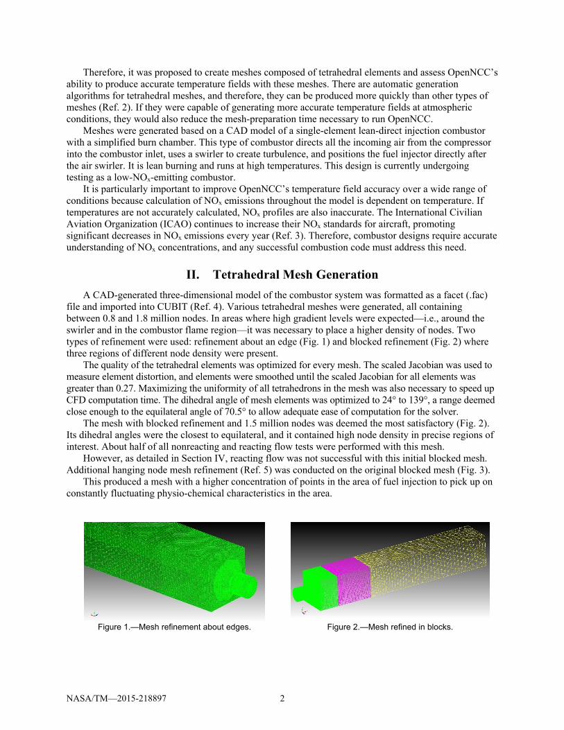
A CAD-generated three-dimensional model of the combustor system was formatted as a facet (.fac) file and imported into CUBIT (Ref. 4). Various tetrahedral meshes were generated, all containing between 0.8 and 1.8 million nodes. In areas where high gradient levels were expected—i.e., around the swirler and in the combustor flame region—it was necessary to place a higher density of nodes. Two types of refinement were used: refinement about an edge (Fig. 1) and blocked refinement (Fig. 2) where three regions of different node density were present.
The quality of the tetrahedral elements was optimized for every mesh. The scaled Jacobian was used to measure element distortion, and elements were smoothed until the scaled Jacobian for all elements was greater than 0.27. Maximizing the uniformity of all tetrahedrons in the mesh was also necessary to speed up CFD computation time. The dihedral angle of mesh elements was optimized to 24° to 139°, a range deemed close enough to the equilateral angle of 70.5° to allow adequate ease of computation for the solver.
The mesh with blocked refinement and 1.5 million nodes was deemed the most satisfactory (Fig. 2). Its dihedral angles were the closest to equilateral, and it contained high node density in precise regions of interest. About half of all nonreacting and reacting flow tests were performed with this mesh.
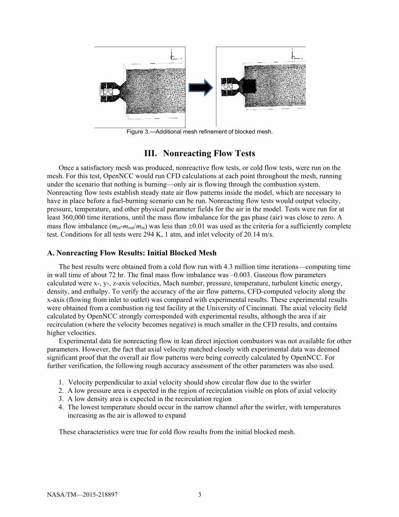
However, as detailed in Section IV, reacting flow was not successful with this initial blocked mesh. Additional hanging node mesh refinement (Ref. 5) was conducted on the original blocked mesh (Fig. 3).
This produced a mesh with a higher concentration of points in the area of fuel injection to pick up on constantly fluctuating physio-chemical characteristics in the area.
Figure 1.—Mesh refinement about edges. Figure 2.—Mesh refined in blocks.
NASA/TM—2015-218897 3
Figure 3.—Additional mesh refinement of blocked mesh.
III. Nonreacting Flow Tests
Once a satisfactory mesh was produced, nonreactive flow tests, or cold flow tests, were run on the mesh. For this test, OpenNCC would run CFD calculations at each point throughout the mesh, running under the scenario that nothing is burning—only air is flowing through the combustion system. Nonreacting flow tests establish steady state air flow patterns inside the model, which are necessary to have in place before a fuel-burning scenario can be run. Nonreacting flow tests would output velocity, pressure, temperature, and other physical parameter fields for the air in the model. Tests were run for at least 360,000 time iterations, until the mass flow imbalance for the gas phase (air) was close to zero. A mass flow imbalance (min-mout/min) was less than 0.01 was used as the criteria for a sufficiently complete test. Conditions for all tests were 294 K, 1 atm, and inlet velocity of 20.14 m/s.
A. Nonreacting Flow Results: Initial Blocked Mesh
The best results were obtained from a cold flow run with 4.3 million time iterations—computing time in wall time of about 72 hr. The final mass flow imbalance was –0.003. Gaseous flow parameters calculated were x-, y-, z-axis velocities, Mach number, pressure, temperature, turbulent kinetic energy, density, and enthalpy. To verify the accuracy of the air flow patterns, CFD-computed velocity along the x-axis (flowing from inlet to outlet) was compared with experimental results. These experimental results were obtained from a combustion rig test facility at the University of Cincinnati. The axial velocity field calculated by OpenNCC strongly corresponded with experimental results, although the area if air recirculation (where the velocity becomes negative) is much smaller in the CFD results, and contains higher velocities.
Experimental data for nonreacting flow in lean direct injection combustors was not available for other parameters. However, the fact that axial velocity matched closely with experimental data was deemed significant proof that the overall air flow patterns were being correctly calculated by OpenNCC. For further verification, the following rough accuracy assessment of the other parameters was also used.
1. Velocity perpendicular to axial velocity should show circular flow due to the swirler 2. A low pressure area is expected in the region of recirculation visible on plots of axial velocity 3. A low density area is expected in the recirculation region 4. The lowest temperature should occur in the narrow channel after the swirler, with temperatures
increasing as the air is allowed to expand
These characteristics were true for cold flow results from the initial blocked mesh.
NASA/TM—2015-218897 4
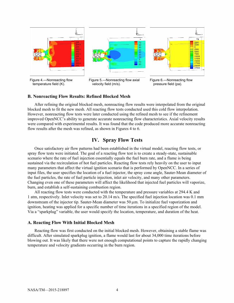
Figure 4.—Nonreacting flow
temperature field (K). Figure 5.—Nonreacting flow axial
velocity field (m/s). Figure 6.—Nonreacting flow
pressure field (pa).
B. Nonreacting Flow Results: Refined Blocked Mesh
After refining the original blocked mesh, nonreacting flow results were interpolated from the original blocked mesh to fit the new mesh. All reacting flow tests conducted used this cold flow interpolation. However, nonreacting flow tests were later conducted using the refined mesh to see if the refinement improved OpenNCC’s ability to generate accurate nonreacting flow characteristics. Axial velocity results were compared with experimental results. It was found that the code produced more accurate nonreacting flow results after the mesh was refined, as shown in Figures 4 to 6.
IV. Spray Flow Tests
Once satisfactory air flow patterns had been established in the virtual model, reacting flow tests, or spray flow tests were initiated. The goal of a reacting flow test is to create a steady-state, sustainable scenario where the rate of fuel injection essentially equals the fuel burn rate, and a flame is being sustained via the recirculation of hot fuel particles. Reacting flow tests rely heavily on the user to input many parameters that affect the virtual ignition scenario that is performed by OpenNCC. In a series of input files, the user specifies the location of a fuel injector, the spray cone angle, Sauter-Mean diameter of the fuel particles, the rate of fuel particle injection, inlet air velocity, and many other parameters. Changing even one of these parameters will affect the likelihood that injected fuel particles will vaporize, burn, and establish a self-sustaining combustion region.
All reacting flow tests were conducted with the temperature and pressure variables at 294.4 K and 1 atm, respectively. Inlet velocity was set to 20.14 m/s. The specified fuel injection location was 0.1 mm downstream of the injector tip. Sauter-Mean diameter was 50 m. To initialize fuel vaporization and ignition, heating was applied for a specific number of time iterations in a specified region of the model. Via a “sparkplug” variable, the user would specify the location, temperature, and duration of the heat.
A. Reacting Flow With Initial Blocked Mesh
Reacting flow was first conducted on the initial blocked mesh. However, obtaining a stable flame was difficult. After simulated sparkplug ignition, a flame would last for about 34,000 time iterations before blowing out. It was likely that there were not enough computational points to capture the rapidly changing temperature and velocity gradients occurring in the burn region.
NASA/TM—2015-218897 5
B. Reacting Flow With Refined Blocked Mesh
To improve the code’s ability to generate a sustainable flame, the density of points near the fuel injector was increased. With more points to pick up temperature changes in the fuel vaporization/burn region, it was more likely that the code would be able to output accurate combustion results. The initial heating element was set to 1800 °F for 20,000 time iterations in a 20 mm-diameter cylinder, heating from 4 to 40 mm downstream of the fuel injector tip. Initial fuel cone angle was set to 60°. Once the flame had self-sustained for more than 35,000 time iterations, the cone angle was gradually set to 90°, with a half-cone angle of 40°.
V. Results and Discussion
It was found that when OpenNCC is run on tetrahedral meshes, it is capable of generating extremely accurate nonreacting flow results, and a semisustainable flame in reacting flow cases. It remains to be seen if tetrahedral meshes can aid in the generation of accurate temperature fields under these conditions. However, it is likely that further changes in the input parameters for reacting flow cases will enable OpenNCC to produce temperature fields that closely mirror experimental results. Because tetrahedral meshes can be quickly created from CAD models, they provide an attractive tool for use with OpenNCC.
VI. Conclusion
A preliminary version of OpenNCC was tested to assess its accuracy in generating steady-state temperature fields for combustion systems at atmospheric conditions using three-dimensional tetrahedral meshes. Meshes were generated from a CAD model of a single-element lean-direct injection combustor, and the latest version of OpenNCC was used to calculate combustor temperature fields. OpenNCC was shown to be capable of generating sustainable reacting flames using a tetrahedral mesh, and the subsequent results were compared to experimental results. While nonreacting flow results closely matched experimental results, a significant discrepancy was present between the code’s reacting flow results and experimental results. When wide air circulation regions with high velocities were present in the model, this appeared to create inaccurately high temperature fields. Conversely, low recirculation velocities caused low temperature profiles. In the future, these observations will allow for more educated modification of reacting flow input parameters that can improve the ability of OpenNCC in producing temperature fields that closely mirror experimental results.
References
1. Wey, Thomas, and Nan-Suey Liu. Simulation of Single-Element Lean-Direct Injection Combustor Using Arbitrary Polyhedral Mesh. Tech. N.p.: American Institute of Aeronautics and Astronautics, n.d. Print.
2. Tautges, Timothy J. “Mesh Generation.” Lecture. Sandia National Laboratories, Oct. 2004. Web. 6 June 2013.
3. “US EPA Aligns with ICAO on New NOx Standards for Aircraft Engines as FAA Pledges Action on GA Leaded Fuel.” GreenAir Online.com. GreenAir Communications, 9 July 2012. Web. 5 June 2013.
4. CUBIT. Computer software. https://cubit.sandia.gov/. Vers. 14.0. Sandia National Laboratories, n.d. Web. 3 June 2013.
5. Wey, Thomas, and Nan-Suey Liu. Simulation of Single-Element Lean-Direct Injection Combustor Using a Polyhedral Mesh Derived from Hanging-Node Elements. Tech. N.p.: American Institute of Aeronautics and Astronautics, n.d. Print.