Embed Size (px)
Citation preview

Atomic Force Microscope
Fundamental Principles
-Joy BhattacharjeeIIT Kanpur.
Co-Founder & Director,Kanopy Techno Solutions

MicroscopesOptical
Simple
Compound
Stereoscopic
Confocal
X-Ray
STXM
TXM
XPEEM
Electron
TEM
SEM
STEM
REM
Probe
STM
EC-STM
MFM
CFM
EFM
AFM
C-AFM
Acoustic
SAM
C-SAM
Neutron
Invented by IBM Scientists in 1986
Gerd Binnig and Heinrich Rohrer
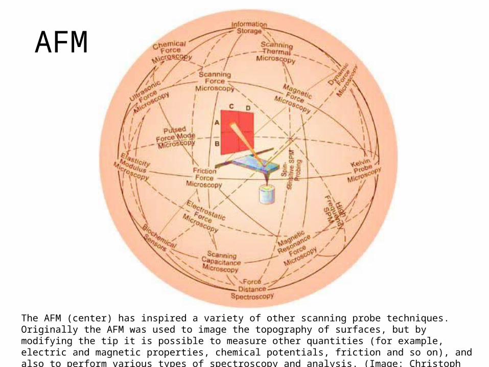
AFM
The AFM (center) has inspired a variety of other scanning probe techniques. Originally the AFM was used to image the topography of surfaces, but by modifying the tip it is possible to measure other quantities (for example, electric and magnetic properties, chemical potentials, friction and so on), and also to perform various types of spectroscopy and analysis. (Image: Christoph Gerber; copyright Nature Publishing Group)
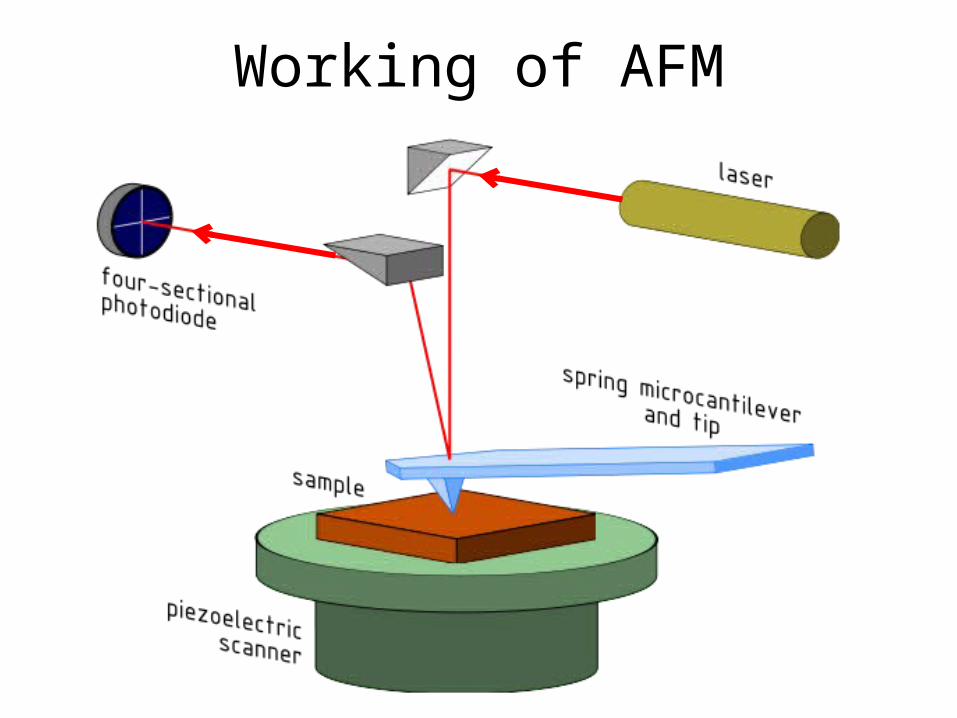
Working of AFM

Working of AFM: Block Diagram

Significant ForcesCapilla
ry
Van Der
Waals Chemical Bond
Electro-Static
Magnetic
Casimir
Solvation

Force in action

Operation
Signal for Post-Processing and Feedback
Non-Contact
TappingContact
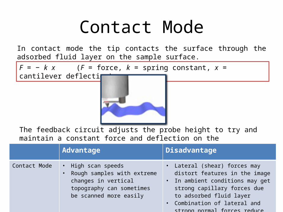
Contact ModeIn contact mode the tip contacts the surface through the adsorbed fluid layer on the sample surface.
The feedback circuit adjusts the probe height to try and maintain a constant force and deflection on the cantilever. This is known as the deflection setpoint.
F = − k x (F = force, k = spring constant, x = cantilever deflection)
Advantage Disadvantage
Contact Mode • High scan speeds• Rough samples with extreme changes
in vertical topography can sometimes be scanned more easily
• Lateral (shear) forces may distort features in the image
• In ambient conditions may get strong capillary forces due to adsorbed fluid layer
• Combination of lateral and strong normal forces reduce resolution and mean that the tip may damage the sample, or vice versa
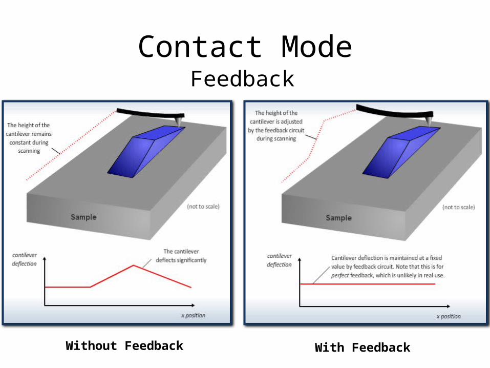
Feedback
Without Feedback With Feedback
Contact Mode
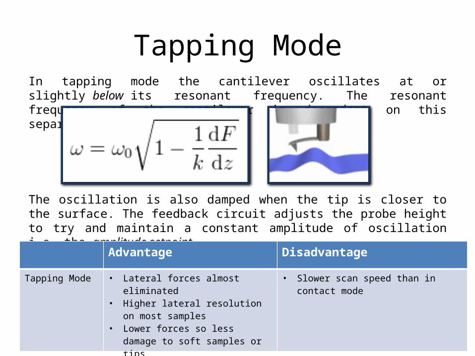
Tapping ModeIn tapping mode the cantilever oscillates at or slightly below its resonant frequency. The resonant frequency of the cantilever is dependent on this separation.
The oscillation is also damped when the tip is closer to the surface. The feedback circuit adjusts the probe height to try and maintain a constant amplitude of oscillation i.e. the amplitude setpoint.
Advantage Disadvantage
Tapping Mode • Lateral forces almost eliminated• Higher lateral resolution on most
samples• Lower forces so less damage to soft
samples or tips
• Slower scan speed than in contact mode
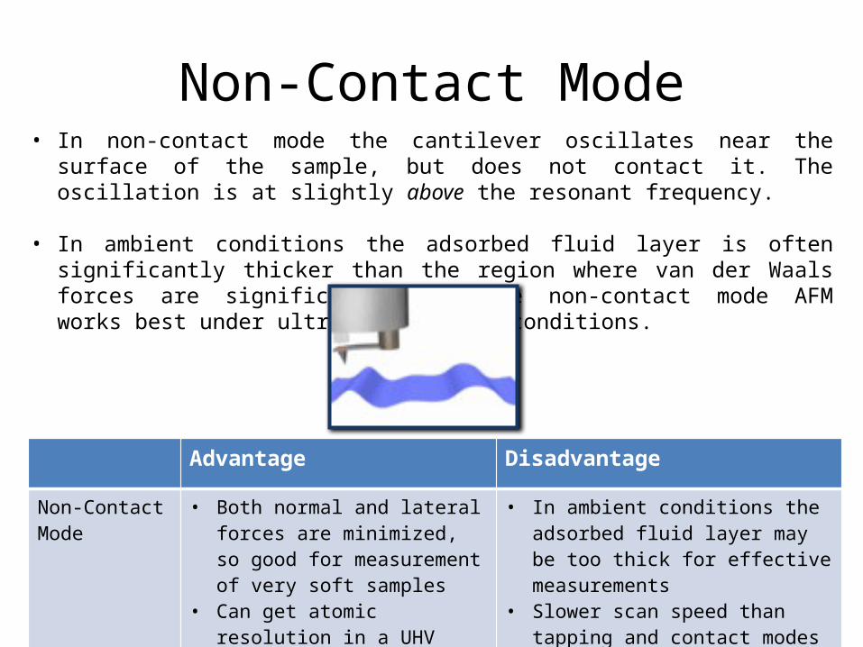
Non-Contact Mode• In non-contact mode the cantilever oscillates near the surface of the sample, but does
not contact it. The oscillation is at slightly above the resonant frequency.
• In ambient conditions the adsorbed fluid layer is often significantly thicker than the region where van der Waals forces are significant. Therefore non-contact mode AFM works best under ultra-high vacuum conditions.
Advantage Disadvantage
Non-Contact Mode
• Both normal and lateral forces are minimized, so good for measurement of very soft samples
• Can get atomic resolution in a UHV environment
• In ambient conditions the adsorbed fluid layer may be too thick for effective measurements
• Slower scan speed than tapping and contact modes to avoid contacting the adsorbed fluid layer

Effect of Shape of Tip

Details of Parts of AFM
Property Typical Value Desired Quality
Material Silicon, Silicon Nitride, Silicon Oxide
Hard, Unreactive
Tip Radius < 10 nm Small
Tip Height 15-20 µm Mechanically stable
Cantilever Length
100-250 µm Appropriate reach
Mean Width 20 – 70 µm Mechanically stable
Half Cone Angle 25° Sample dependent
Base Shape configurable Sample dependent
Apex Shape configurable Sample dependent
Resonant Frequency
Several kHz, depends on shape
Matching piezo’s resonant frequency
Coating None, Gold, Platinum, Diamond
Experiment dependent
Cantilever and Tip

Details of Parts of AFMShapes of AFM Tip

Details of Parts of AFMShapes of AFM Tip
Protruding from the Very
End
Positioned at the Very End
Square-Based Pyramid
Rectangular-based
Pyramid
Circular Symmetric Spike

Details of Parts of AFMHigh Aspect Ratio Spike
AFM Tips
Focused Ion Beam
Electron Beam Deposited
Carbon Nanotube
Plateau Rounded Sphere
Critical Dimension
Details of Parts of AFMScanner
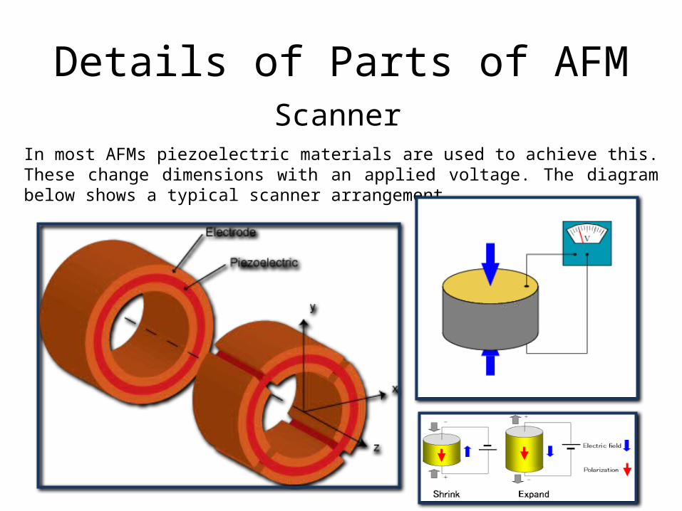
In most AFMs piezoelectric materials are used to achieve this. These change dimensions with an applied voltage. The diagram below shows a typical scanner arrangement.

Details of Parts of AFMScanner
The presence of electrical resonances and anti-resonances make the piezoelectric impedance unique. The resonances result from the electrical input signal exciting a mechanical resonance in the piezo element.
Equivalent Circuit Model

Details of Parts of AFMFeedback
The feedback system is affected by three main parameters:
1. Setpoint2. Feedback gains3. Scan rate
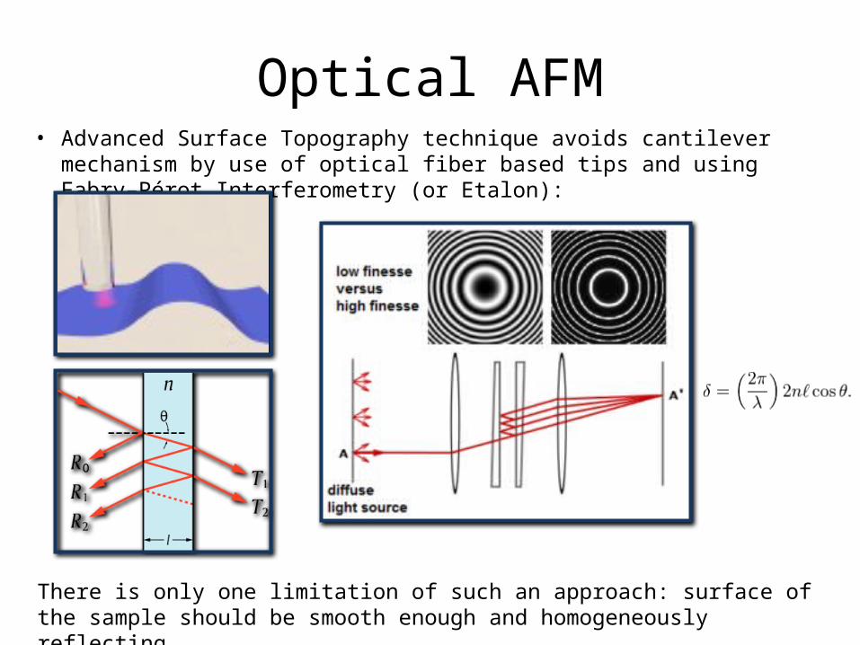
Optical AFM• Advanced Surface Topography technique avoids cantilever mechanism by use of optical
fiber based tips and using Fabry–Pérot Interferometry (or Etalon):
There is only one limitation of such an approach: surface of the sample should be smooth enough and homogeneously reflecting.

Artefacts in AFMScanner Related
Hysteresis
The piezoelectric’s response to an applied voltage is not linear. This gives rise to hysteresis.

Artefacts in AFMScanner Related
Scanner creep
If the applied voltage suddenly changes, then the piezo-scanner’s response is not all at once. It moves the majority of the distance quickly, then the last part of the movement is slower. This slow movement will cause distortion, known as creep.
Change in x-offset Change in y-offset Change in size
Artefacts in AFMScanner Related
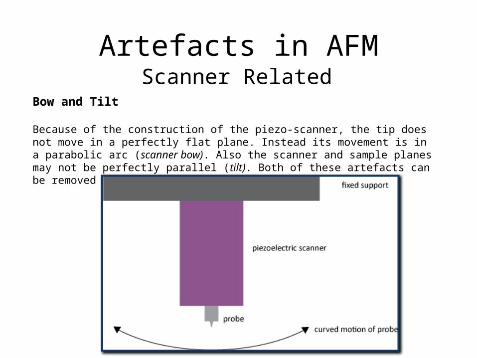
Bow and Tilt
Because of the construction of the piezo-scanner, the tip does not move in a perfectly flat plane. Instead its movement is in a parabolic arc (scanner bow). Also the scanner and sample planes may not be perfectly parallel (tilt). Both of these artefacts can be removed by using post-processing software.
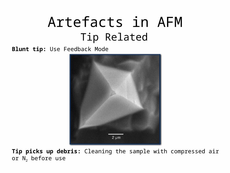
Artefacts in AFMTip Related
Blunt tip: Use Feedback Mode
Tip picks up debris: Cleaning the sample with compressed air or N2 before use

Artefacts in AFMFeedback Related
Poor tracking due to high scan rate
Gains are set too high, then the feedback circuit can begin to oscillate. This causes high frequency noise
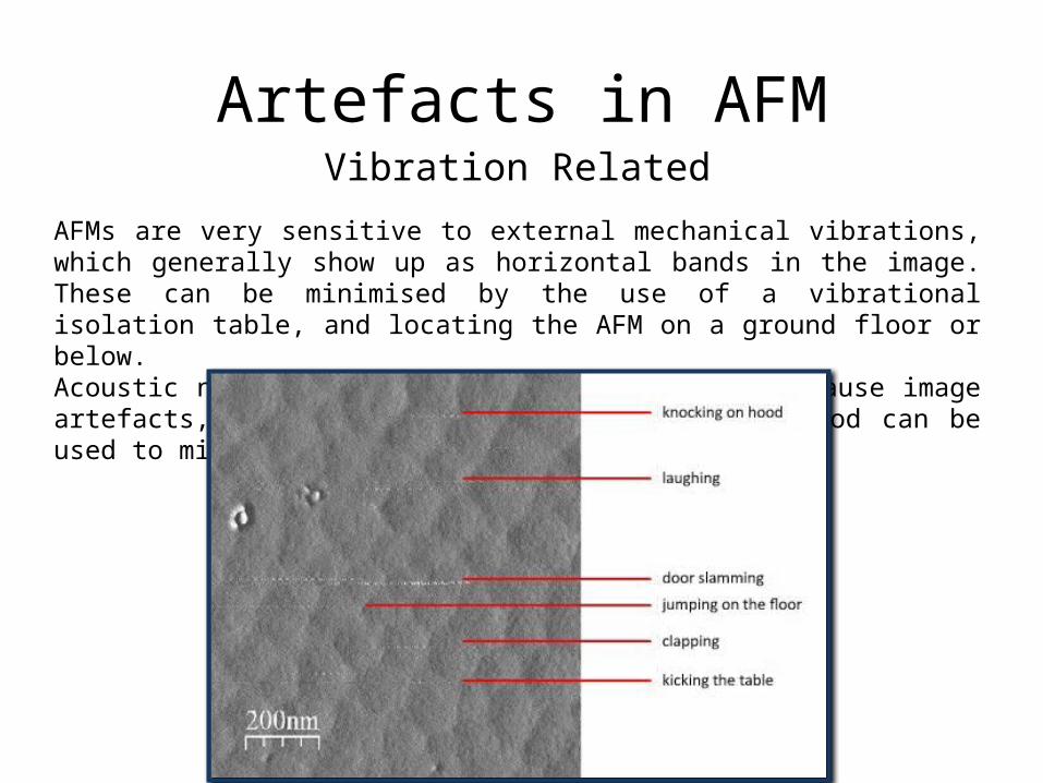
Artefacts in AFMVibration Related
AFMs are very sensitive to external mechanical vibrations, which generally show up as horizontal bands in the image. These can be minimised by the use of a vibrational isolation table, and locating the AFM on a ground floor or below.Acoustic noise such as people talking can also cause image artefacts, as can drafts of air. An acoustic hood can be used to minimise the effects of both of these.

Beyond just surfaceSeeing the atomic orbital
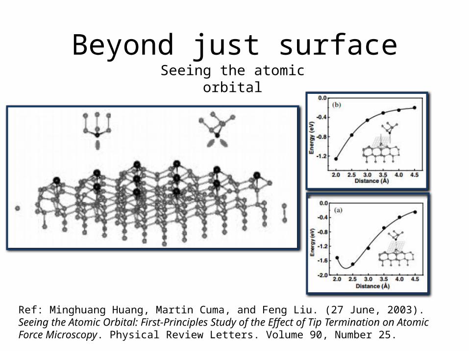
Beyond just surfaceSeeing the atomic orbital
Ref: Minghuang Huang, Martin Cuma, and Feng Liu. (27 June, 2003). Seeing the Atomic Orbital: First-Principles Study of the Effect of Tip Termination on Atomic Force Microscopy. Physical Review Letters. Volume 90, Number 25.
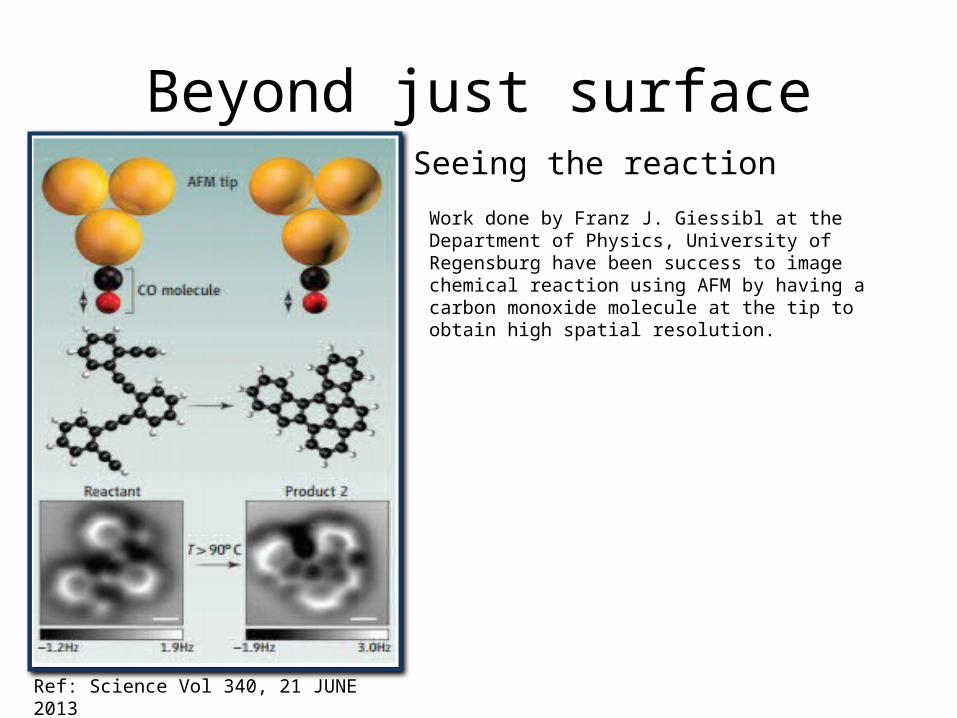
Beyond just surfaceSeeing the reactionWork done by Franz J. Giessibl at the Department of Physics, University of Regensburg have been success to image chemical reaction using AFM by having a carbon monoxide molecule at the tip to obtain high spatial resolution.
Ref: Science Vol 340, 21 JUNE 2013