Embed Size (px)
Citation preview
SAMSUNG Proprietary-Contents may change without notice
7. Level 2 Repair
7-1
This Document can not be used without Samsung's authorization
7-1. Disassembly and Assembly Instructions
7-1-1. Disassembly
Separate 2 connectors.3 Separate the PBA from Front Ass'y.4
Unscrew Rear Case1 Separate the Rear Case2
1
23
4
Unscrew 4 points on Rear Case.Separate Rear part corner using
a decomposition tool.
Separate 2 connectors from the PBA with care. Lift the Hook & Separate the PBA from Front Ass'y.
SAMSUNG Proprietary-Contents may change without notice
7. Level 2 Repair
7-2
This Document can not be used without Samsung's authorization
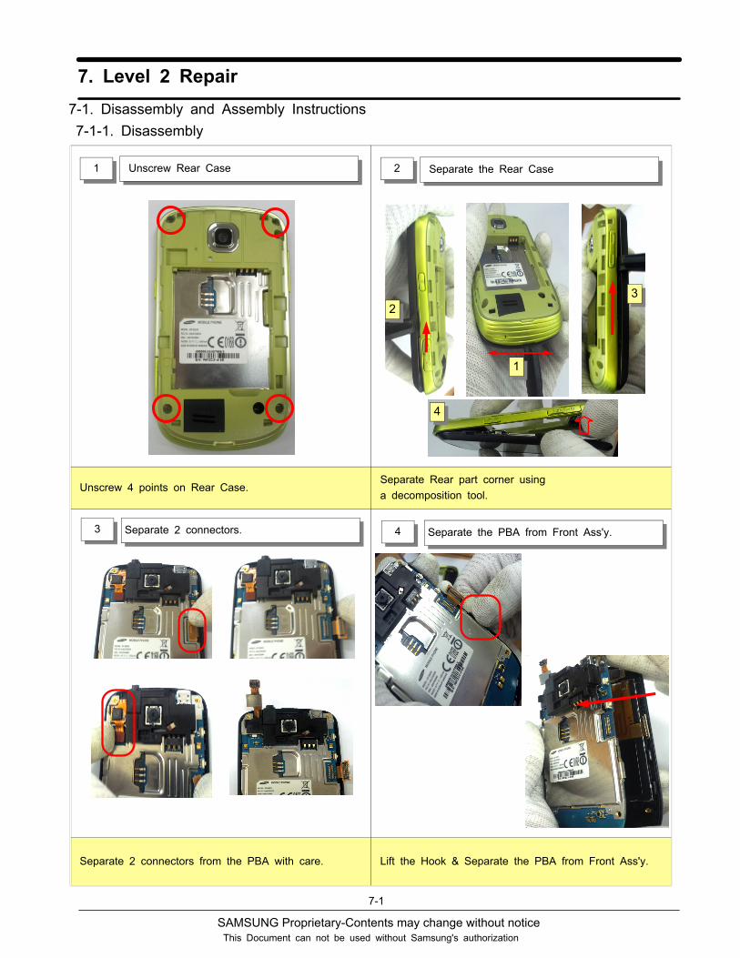
Unscrew PBA5 Separate Shield Can6
Separate the Receiver-FPCB from LCD.7
Unscrew 4 points on the PBA. Separate the Shield Can.
Separate Receiver-FPCB to Open lever of ZIP-TYPE connector.
SAMSUNG Proprietary-Contents may change without notice
7. Level 2 Repair
7-3
This Document can not be used without Samsung's authorization
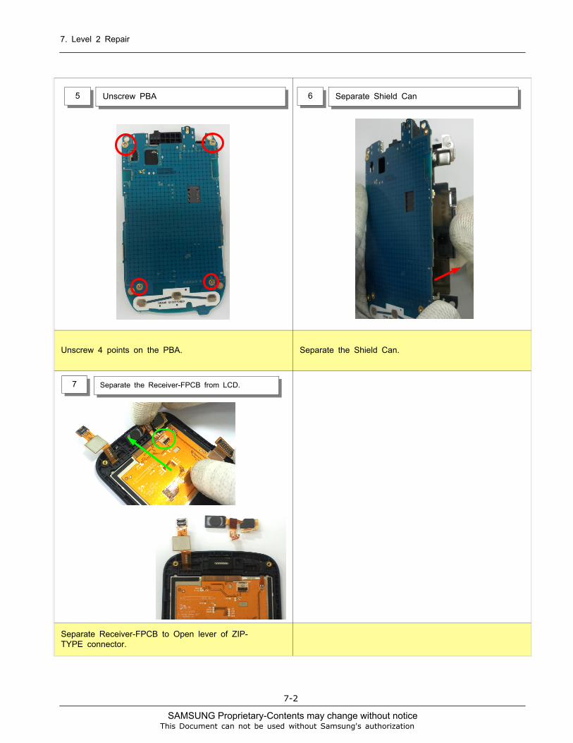
7-1-2. Assembly
Insert the Rubber on the Sensor.1 Assemble the Receiver Module.2
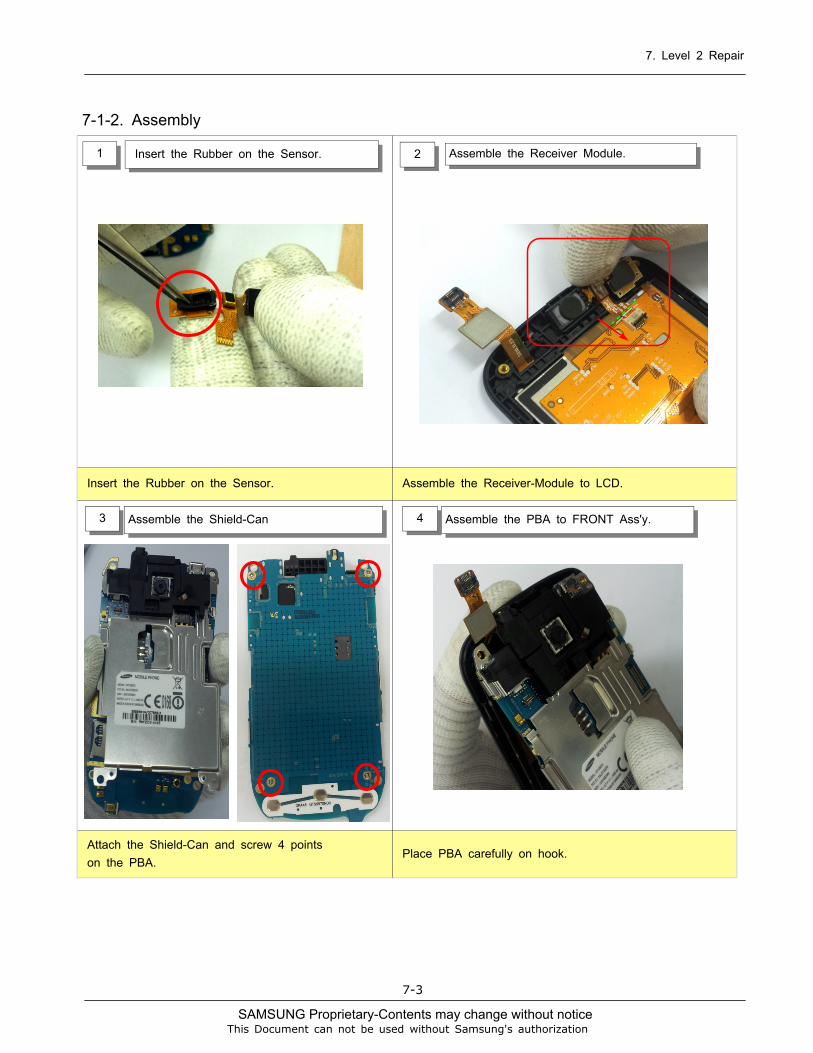
Assemble the Shield-Can3 Assemble the PBA to FRONT Ass'y.4
Insert the Rubber on the Sensor. Assemble the Receiver-Module to LCD.
Attach the Shield-Can and screw 4 points
on the PBA.Place PBA carefully on hook.
SAMSUNG Proprietary-Contents may change without notice
7. Level 2 Repair
7-4
This Document can not be used without Samsung's authorization
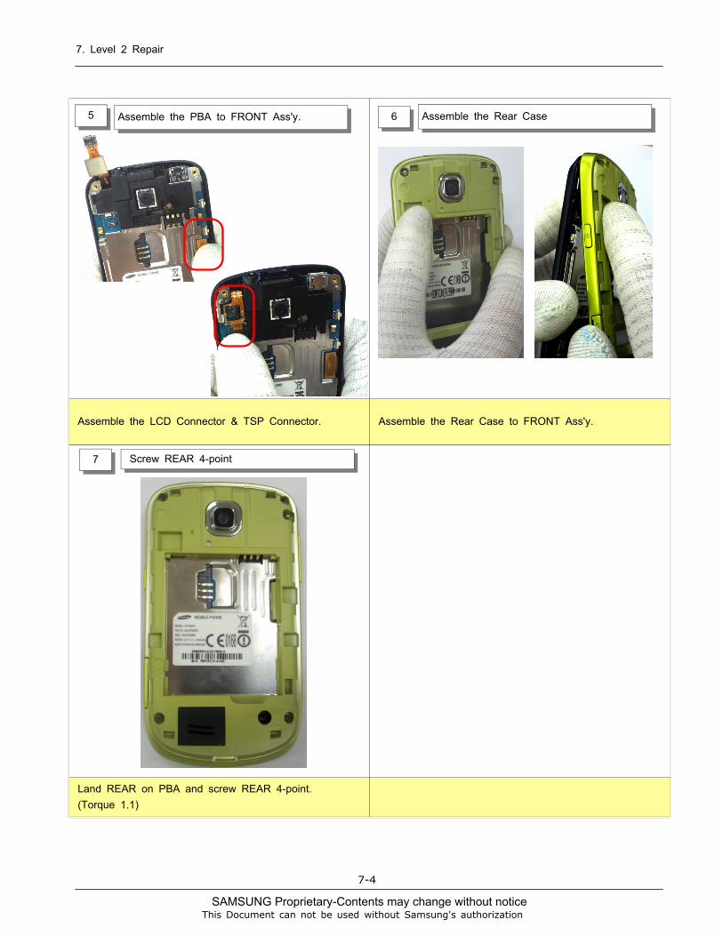
Assemble the PBA to FRONT Ass'y.5 Assemble the Rear Case6
7 Screw REAR 4-point
Assemble the LCD Connector & TSP Connector. Assemble the Rear Case to FRONT Ass'y.
Land REAR on PBA and screw REAR 4-point.
(Torque 1.1)


![Disassembly & Assembly Guide [ Galaxy S8 ] - Microsofteconnectstorage1.blob.core.windows.net/elearning33/objects/1446a5a... · - This document cannot be used without Samsung’s Authorization](https://img.pdfslide.us/doc/110x75/5add38f87f8b9a9d4d8cd7bc/disassembly-assembly-guide-galaxy-s8-micro-this-document-cannot-be-used-without.jpg)


![Disassembly & Assembly Guide [ Galaxy S8 ]](https://img.pdfslide.us/doc/110x75/623ab4e5103b9851402a8ef6/disassembly-amp-assembly-guide-galaxy-s8-.jpg)

![Pop S5570-Android 4.4.3 KitKat CM11 Stable ROM [CM 11].pdf](https://img.pdfslide.us/doc/110x75/55cf9392550346f57b9dd6dc/pop-s5570-android-443-kitkat-cm11-stable-rom-cm-11pdf.jpg)