Embed Size (px)
Citation preview

Wireless NetworksLecture
Dr .Ekhlas Kadhum Hamza
Dept. of Electrical Eng.Baghdad University
Master courseSecond semester
1.4.2015

2
Lecture Outline IEEE 802.11 Data Link Layer IEEE 802.11 Medium Access Control, IEEE 802.11 MAC Sublayer, HIPERLAN Family of Standards, Performance of a Bluetooth Piconet in the
Presence of IEEE 802.11 WLANs Architecture of a Wireless Wide-Area
Network (WWAN) WWAN Subsystem Entities(User Equipment)
3
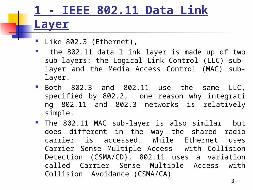
1 - IEEE 802.11 Data Link Layer Like 802.3 (Ethernet), the 802.11 data l ink layer is made up of two sub-layers: the Logical
Link Control (LLC) sub- layer and the Media Access Control (MAC) sub-layer.
Both 802.3 and 802.11 use the same LLC, specified by 802.2, one reason why integrati ng 802.11 and 802.3 networks is relatively simple.
The 802.11 MAC sub-layer is also similar but does different in the way the shared radio carrier is accessed. While Ethernet uses Carrier Sense Multiple Access with Collision Detection (CSMA/CD), 802.11 uses a variation called Carrier Sense Multiple Access with Collision Avoidance (CSMA/CA)

4
1 -IEEE 802.11 Data Link Layer In CSMA/CA a station that intends to transmit ‘listens’ for traffic on
the radio carrier frequency and sends if it is clear after a random delay period. If the receiving station receives the packet intact it sends an acknowledgement (ACK) to confirm the packet has been received. If the transmitting station does not receive an ACK it assumes a collision occurred and transmits again after a random delay period.
Another aspect of the 802.11 data link layer that is different than Ethernet is the use of a packet fragmentation and CRC error checking with each packet. Ether net implements these functions at higher pr otocol layers whereas 802.11 fragments packets and uses CRC at the data link layer. This allows the WLAN to send smaller packets that are less likely to be corrupted by interference, decreasing the need for re-transmissions.

5
IEEE 802.11 Medium Access Control MAC layer covers three functional areas:
Reliable data delivery Access control Security

6
Reliable Data Delivery More efficient to deal with errors at the MAC
level than higher layer (such as TCP) Frame exchange protocol
Source station transmits data Destination responds with acknowledgment (ACK) If source doesn’t receive ACK, it retransmits frame
Four frame exchange Source issues request to send (RTS) Destination responds with clear to send (CTS) Source transmits data Destination responds with ACK

7

8
Comparison of MAC access schemes in wireless networks.

9
IEEE 802.11 Medium Access Control Wireless local area networks operate using a shared, high bit rate
transmission medium to which all devices are attached and information frames relating to all calls are transmitted. MAC sublayer defi nes how a user obtains a channel when he or she needs one.
The 802.11 MAC layer provides for two other robustness features: cycle redundancy check (CRC) checksum and packet fragmentation. Each packet has a CRC checksum calculated and attached to ensure that the data was not corrupted in transmit. This is different from the Ethernet, where higher-level protocols such as TCP handle error checking

10
IEEE 802.11 MAC Sublayer In IEEE 802.11, the MAC sublayer is responsible for asynchronous data
service (e.g., exchange of MAC service data units (MSDUs)), security service (confidentiality, authentication, access control in conjunction with layer management), and MSDU ordering
The MAC frame contains addressing informa- tion, information to set the network allocation vector (NAV), and a frame check sequence to verify the integrity of the frame. The general IEEE 802.11 MAC frame format is shown in Figure
The MAC frame format contains four address fi elds. Any particular frame type may contain one, two, three, or four address fi elds. The address format in IEEE 802.11-1997 is a 48-bit address, used to identify the source and destination of MAC addresses contained in a frame, as IEEE 802.3. In addition to source address (SA) and destination address (DA), three additional address types are defi ned: the transmitter address, the receiver address (RA), and the basic service set identifi er (BSSID). The BSSID is a unique identifi er for a particular basic ser- vice set of the IEEE 802.11 WLAN. In an infrastructure basic service set, the BSSID is the MAC address of the AP

11
The general IEEE 802.11 MAC frame format
is 35 to 50 meters. HIPERLAN/1 provides quality of service (QoS), which lets critical traffi c be prioritized.

12
HIPERLAN Family of Standards •HIPERLAN/1 is aligned with the IEEE 802 family of standards and is very much like a modern wireless Ethernet. HIPERLAN/1, a standard completed and ratified in 1996, defines the operation of the lower portion of the OSI reference model, namely the data link layer and physical layer•The HIPERLAN MAC layer defines the various protocols which provide the HIPERLAN/1 features of power conservation, security, and multihop routing (i.e., support for forwarding), as well as the data transfer service to the upper layers of protocols•HIPERLAN/1 uses the same modulation technology that is used in GSM, Gaussian minimum shift keying (GMSK). It has an over air data rate of 23.5 Mbps and maximum user data rate (per channel) of over 18 Mbps. The range in a typical indoor environment is 35 to 50 meters. HIPERLAN/1 provides quality of service (QoS), which lets critical traffic be prioritized.

13
Table : A comparison of HIPERLAN/2 and IEEE 802.11.

14
Performance of a Bluetooth Piconet in the Presence of IEEE 802.11 WLANs Due to its global availability, the 2.4 GHz ISM unlicensed band
is a popular frequency band to low-cost radios. Bluetooth and the IEEE 802.11 WLAN both operate in this band. Therefore, it is anticipated that some interference will result from both these systems operating in the same environment. Interference may lead to significant performance degradation.
The collision probability of Bluetooth to the IEEE 802.11 frequncy hopping ( FH ) system is 1/79. In the IEEE 802.11 direct sequence (DS), the data stream is converted into a symbol stream which spreads over a relatively wide band channel of 22 MHz, so the interference on a Bluetooth packet from IEEE 802.11 DS system is much higher than that from the 802.11 FH system. It is because the bandwidth of a channel in DS is 22 times as wide as Bluetooth one channel. The collision probability of Bluetooth to the IEEE 802.11 DS system is 22/79.

15
PER from M Neighboring IEEE 802.11 WLANs*
Under IEEE 802.11 FH, the probability of M IEEE 802.11 induced collisions on a Bluetooth packet is given as
Under IEEE 802.11 DS, the probability of M IEEE 802.11 induced collisions on a Bluetooth packet is given as:

16

17
Architecture of a Wireless Wide-Area Network (WWAN)
A wireless network does not operate in isolation; it uses the services of public switched telephone networks (PSTNs) to make or receive calls from wireline users.
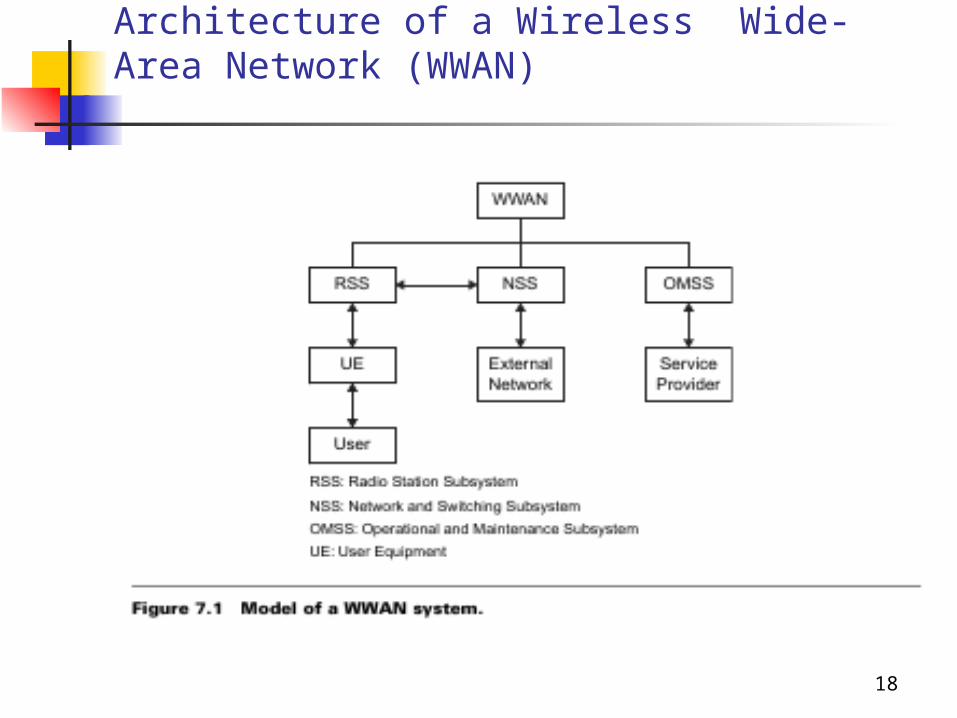
A number of functions is required to support the services and facilities in a wireless wide-area network (WWAN). The basic subsystems of the WWAN are: radio station subsystem (RSS), networking and switching subsystem (NSS), and operational and maintenance subsystem (OMSS)( see fig 7.1)
The radio subsystem is responsible for providing and managing transmission paths between the user equipment and the NSS. This includes management of the radio interface between the user equipment and the rest of the WWAN system. The NSS has the responsibility of managing communications and connecting user equipment to the relevant networks or other users. The NSS is not in direct contact with the user equipment, nor is the radio subsystem in direct contact with external networks.
18
Architecture of a Wireless Wide-Area Network (WWAN)
19
Architecture of a Wireless Wide-Area Network (WWAN)
The user equipment, radio subsystem, and NSS form the operational part of the WWAN system. The OMSS provides the means for a service provider to control them. Figure 7.1 shows the model for the WWAN system. In the WWAN, interaction between the subsystems can be grouped into two main parts :
Operational part: External Networks ⇔ NSS ⇔ RSS ⇔ UE ⇔ User Control and maintenance part: OMSS ⇔ Service Provider

20
WWAN Subsystem Entities
Figure 7.2 shows the functional entities of a WWAN and their logical interaction. A brief description of these functional entities is provided belowUser Equipment

21
WWAN Subsystem Entities

22
Assignment Example 21.5 Example 21.6 Example 21.7