Embed Size (px)
Citation preview

- V. Tejasree
VAPORIZERS

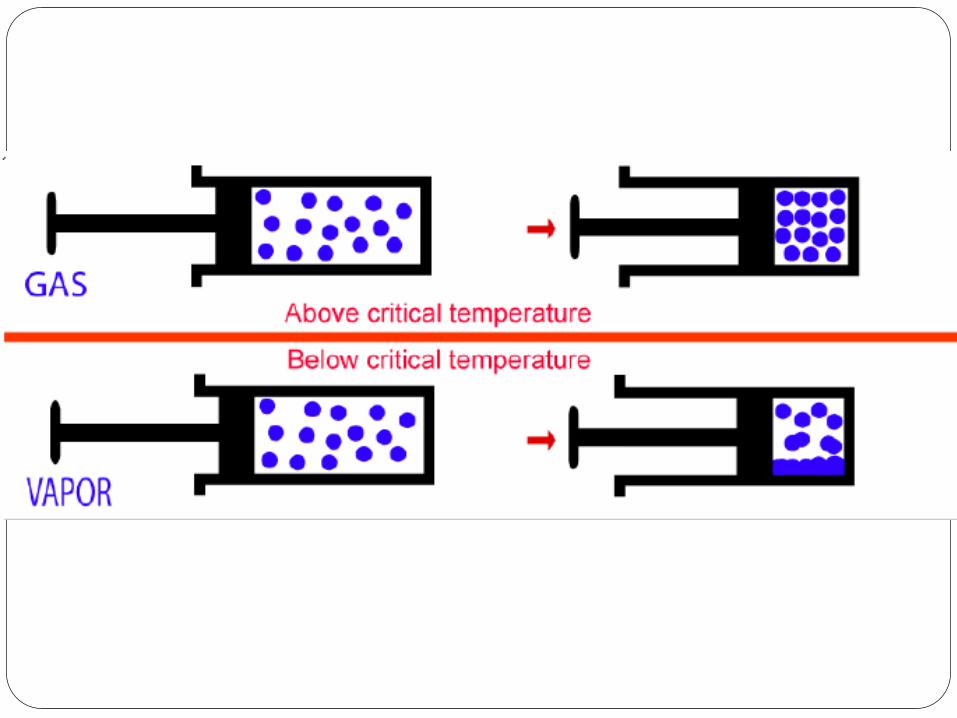
What is a vapor?
What is a gas?
What is vaporiser?

Vapor- gaseous state of a substance which at
room temperature and pressure is a liquid.
Gas- Is a substance which at room temperature
and pressure exists only in gaseous state
Vaporiser – is a device that changes a liquid
anesthetic agent into its vapor and adds a
controlled amount of that vapor to the fresh gas
flow or the breathing system.
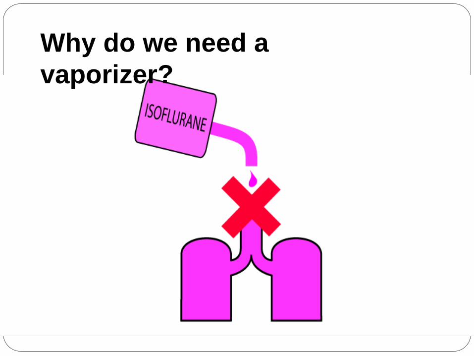
Why do we need a
vaporizer?

Most volatile, potent inhaled agents exists as a
liquid at room temperature and atmospheric
pressure.
Vaporizers are needed them to convert the liquid-
form of the anesthetic to vapor phase and add a
certain amount of this vapor to the anesthetic
circuit.

History
1540- Valerius Cordus- Ether- sweet oil of vitriol
1800- Humphry Davy- Nitrous oxide
1842- William E.Clarke &Crawford W. Long
1844- Horace Wells
1844- E.R. Smilie

1846
William Thomas Green Morton- American dentist
16th october 1846 in Massachusetts General
hospital, boston.


1847
John snow
First specialist anesthetist
Snow ether inhaler


1862
Joseph thomas clover
British physician
Clover chloroform apparatus


1879 - Esmarch Open drop mask


1890 Schimmelbusch

regulator
Augustus George vernon
Harcourt
English chemist


1908
Omberdanne ether inhaler-
Louis omberdanne
French pediatrician
and plastic surgeon
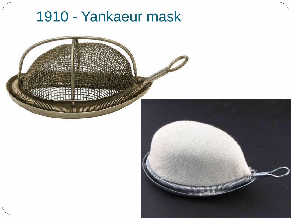
1910 - Yankaeur mask

1912 - Gwathmey-Woolsey Nitrous
Oxide-Oxygen ether Apparatus

1920’s - Boyle’s bottle


Goldman vaporizer

Copper kettle vaporizer

Oxford Miniature Vaporizer
(OMV)
Halothane, enflurane, isflurane and sevoflurane

1952- Epstein Macintosh Oxford
vaporizer (EMO)

Physics related to vaporiser
Vapor pressure
Boiling point
Gas concentration
Partial pressure
Volumes percent
Latent heat of vaporisation
Specific heat
Thermal conductivity

Ideal Gas Law
Gases Behave Predictably.
This behavior is expressed by the:
IDEAL GAS LAW
PV= nrT
P= Pressure
V= Volume
n= number of moles of gas
r= ideal gas law constant
T= Temperature

Vapor pressure
When a liquid is enclosed in a container, the
molecules of the liquid break from the surface
and enter the space above forming a vapor.
These molecules bombard the walls of the
container creating a pressure called vapor
pressure.


Saturated vapor pressure- the pressure exerted
by the vapor when in equilibrium with the liquid
phase at constant temperature
Vapor pressure depends on liquid and
temperature. Independent of ambient pressure.

SVP Varies as a Function of Temperature

Boiling point
Boiling point of a liquid is defined as the
temperature at which vapor pressure equals
atmospheric pressure.
Lower the atmospheric pressure lower the boiling
point.
Agents with low boiling points are more
susceptible to variations in barometric pressure
than agents with higher boiling points

SVP BP
Sevoflurane: 160mmHg 58.6O C
Enflurane: 175mmHg 56.5O C
Isoflurane: 238mmHg 48.5O C
Halothane: 243mmHg 50.2O C
Desflurane: 660mmHg 22.8O C

Gas concentration
Gas concentration can be explained by 2
methods.
1) Partial pressure
2) Volumes percent

Partial pressure
pressure exerted by a gas in a mixture of gases
is the partial pressure of that gas.
Dalton’s lawof partial pressures-
Ptotal = P1+P2+P3…. Pn
The partial pressure of an vapor depends only on
temperature of that agent
The highest partial pressure of a gas is its vapor
pressure at a given temperature.

Volumes percent
Concentration of a gas in a mixture is expressed
as its percentage of total volume.
Number of units of volume of a gas in relation to a
total of 100 units of volume for the total gas
mixture.
Volumes percent expresses the relative ratio of a
gas molecules in a mixture.
Partial pressure expresses an absolute value.

Heat of vaporization
Number of calories required to convert 1gram of a
liquid into a vapor.
Number of calories required to conver 1ml of an
liquid into a vapor

Specific heat
Quantity of heat required to raise the temperature
of 1 gram of the substance by 1C
Amount of heat required to raise the temperature
of 1ml of liquid by 1C
Thermal conductivity
Measure of the speed with which heat flows
through a substance.
Higher the thermal conductivity the better the
substance conducts heat. z


Ideal vaporizer Delivers a fixed desired concentration of the agent
Equal to the concentration on dial setting
Independent of temperature
Independent of flow rate
Independent of carrier gas
No effect on back pressure
Easy to maintain
Easy to clean
Agent specific

Vaporizer Classification (Old)A. Method of Regulating Output Concentration
1. Concentration Calibrated (Variable-Bypass)
2. Measured Flow (Copper Kettle)
B. Method of Vaporization
1. Flow Over
2. Bubble Through
3. Injection
C. Temperature Compensation
1. Thermo Compensation
2. Supplied Heat
D. Specificity
1. Agent Specific
2. Multiple Agent
E. Resistance
1. Plenum
2. Low Resistance

Vaporizers Classification (New)A. Concentration Calibration
1.Variable Bypass Vaporizers
2. Electronic Vaporizers
B. Vaporization Methods
1. Flow Over
2. Injection
C. Temperature Compensation
1. Mechanical Thermo Compensation
2. Supplied Heat
3. Electronic Thermo Compensation

Vaporizer design

Regulating output concentrations
Concentration calibrated / variable bypass
vaporizer
Direct reading/ Dial controlled/ Automatic plenum/
Percentage type/ Tec-type vaporizers.
Output is controlled by a single knob or dial that is
calibrated in volumes percent
Located between flow meters and common gas
outlet.

Should not be between common gas outlet and
breathing systems or in the breathing system.
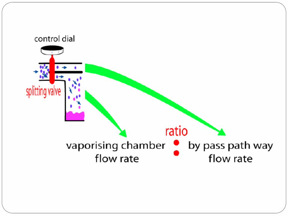
Concentrations are accomplished by splitting the
gas flow that passes through the vaporizer.

Splitting ratio It is the ratio of the resistance of the two pathways.
Ratio of the bypass gas to the gas going to the
vaporizing chamber.
gas going through the bypass
Splitting ratio = gas going through the
vaporizing chamber
It depends on-
a) Variable adjustable orifice of the inlet/outet
b) Total flow to the vaporizer

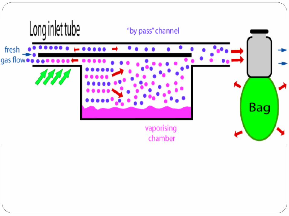
The clinically useful concentrations are
accomplished by splitting gas flows that passes
through the vaporizer.
Some of the gas flow through the vaporizing
chamber and the remainder goes through a
bypass to the vaporizer outlet.
Both gas flows join downstream of the vaporizing
chamber, where gas exits the vaporizer at desired
concentrations.


Electronic vaporizers
They are of 2 types –
a)A computer calculates the volume of carrier gas
necesssary to produce the desired agent
concentration that needs to pass through the
vaporizing chamber
b) Another type withdraws a calculated amount of
liquid agent from the agent bottle and injects the
liquid into breathing system or fresh gas flow.
The amount of liquid is adjusted to achieve the
desired agent concentrations.

Measured flows
The vaporizer heats the anesthetic agent to a
temperature above its boiling point and is then
metered into the fresh gas flow.
A measured flow is sent by a separate oxygen flow
meter to pass to the vaporizer with the output being
at saturated vapor pressure.
To dilute this concentration, output from the flow
meter is combined with gas passing from the main
flow meter.
Flow metered/ flowmeter controlled vaporizer
systems.
Copper – kettle/ Verni- trol and Metomatic
vaporizers.


Vaporization methods
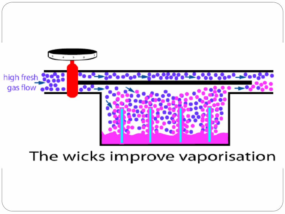
FLOW OVER-
A stream of carrier gas passes over the surface of
the liquid.
Increasing the surface area of the carrier gas –
liquid interface enhances the efficiency.
Baffles / spiral tracks / wicks

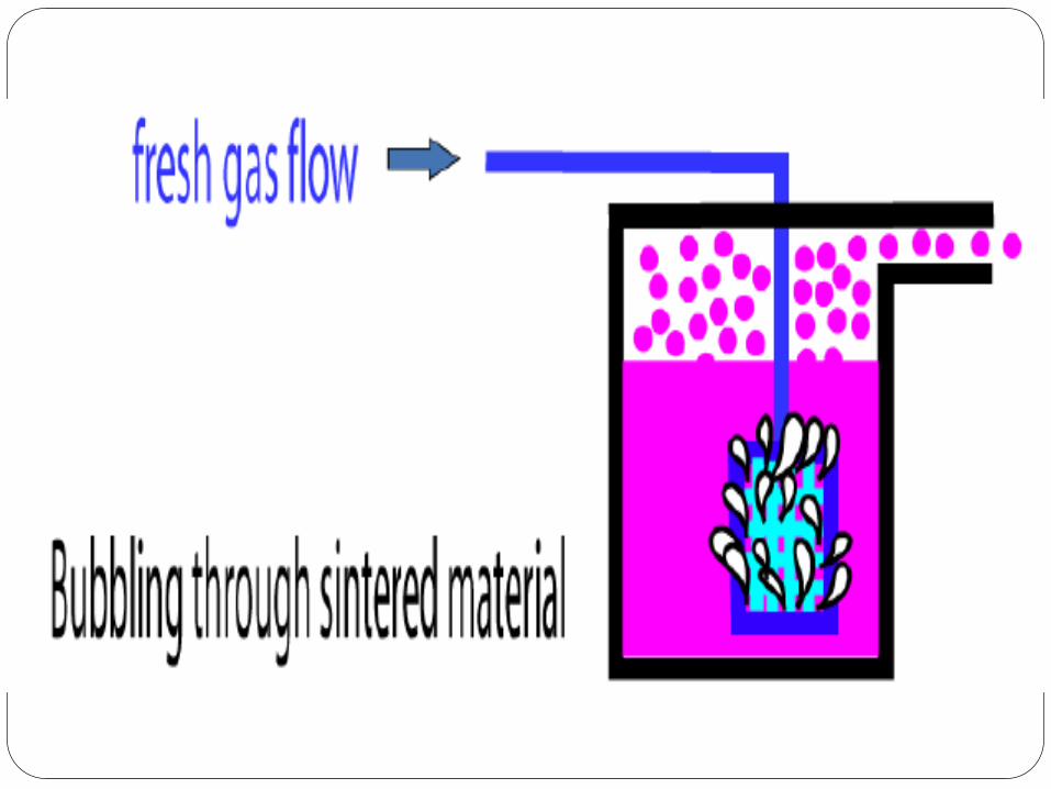
Bubble through
The carrier gas is bubbled through the liquid
anesthetic agent.
A known amount of the liquid is then injected into
the fresh gas flow.
Boyle’s bottle
Sintered diffuser

Injection
Some vaporizers control the vapor concentrations
by injecting a known amount of liquid anesthetic
into a known volume of gas.
How much liquid agent does a vaporizer use per
hour?
Ehrenworth & Eisenkraft gave a formula-
3 x FGF(L/min) x vol% = ml liquid used per hour

Location of vaporizer
Plenum
Low resistance

Plenum
Latin- fullness
Vaporizers with resistance which depend on
compressed gas driven under pressure are
plenum vaporizers.
In these the internal resistance is high such that
the fresh gas flow should be above the
atmospheric pressure.

Low resistance
In these they have a low internal resistance to
gas flow. So these can be used within the
breathing circuit.
The carrier gas is drawn through the vaporizer
either by the patient’s own respiratory efforts or
by a self inflating bag or manual bellows.
they may be used in a
Non-rebreathing draw-over apparatus
In-circuit vaporizer
In a circle absorber system
Eg: goldman vaporizer, stephens vaporizer

Temperature compensation
3 methods are employed to maintain a constant
vapor output with fluctuations in liquid anesthetic
temperature.
a) Mechanical thermocompensation
b) Supplied heat
c) Computerized thermocompensation


Mechanical thermocompensation
The splitting ratio is altered so that the
percentage of carrier gas that is directed through
the vaporizing chamber is increased or
decreased thus compensating changes in vapor
pressure with temperature changes.
As vaporizer cools, the thermal element restricts
the bypass flow, causing more carrier gas to pass
through the vaporizing chamber, vice versa.

2 types of mechanical thermocompensation are
used.
1) Bimettalic strip
2) Invar rod


Bimettalic strip-
2 dissimilar metals or alloys are placed back to
back.
Due to different rates of expansion and
contraction with temperature- Device bends
It can be used to vary the degree of occlusion in
the aperture of the gas channel and thus alter the
flow of carrier gases through it.


Invar rod-
It is a metal alloy with a low coefficient of
expansion.
The bimettalic device consists of a central rod
made of invar, sitting inside a brass jacket, the
top part of which is attached to the roof of
vaporizing chamber.
As the liquid cools, the brass jacket contratcs
more than the invar which is pushed upwards into
the bypass restricting the flow of gas.


Supplied heat-
An electric heater can be used to supply heat to a
vaporizer and maintain it at desired constant
temperature.

Computerized Thermocompensation
It is accomplished by computer control
2 methods.
1) Amount of agent injected into the breathing
system or fresh g an amount of as flow may be
altered.
If the vaporizer withdraws an amount of liquid from
a bottle and inject it, the heat loss due to
vaporization may not be important.
2) The computerized control of the amount of
carrier gas flows through the vaporizing chamber.

Agent specificity
Agent specific
Multiple agent

Effects of intermittent back pressure
When assisted or controlled ventilation is used,
the positive pressure generated during inspiration
is transmitted from the breathing system back to
the machine and the vaporizers.
Back pressure may either
Increase the vaporizer output-Pumping effect
Or
Decrease the vaporizer output- Pressurizing
effect

Pumping effect
Factors effecting pumping effect
Less agent in vaporizing chamber
Carrier gas flow is low
Pressure fluctuations are high and frequent
Dial setting is low


Modifications
Small vaporizing chamber
Increasing size of bypass chamber
Employing a long spiral large diametered tube
leading to vaporizing chamber.
Exclude wicks where the inlet tube joins the
vaporizing chamber
One – way valve


Pressurizing effect
Factors
High flows
Large pressure fluctuations
Low vaporizer settings


Effects of rebreathing
Vaporizer dial setting reflects the concentration of
inhalational agent delivered to the system.
When FGF is high, exhaled gas is rebreathed, and
inspired concentration should be close to the
vaporizer setting
If FGF is low, exhaled gases contirbute a significant
proportion of inspired gases.
If minute volume is increased, more rebreathing and
greater effect.
Agent analyzer

Vaporizers and standards
The effects of variations in ambient temperature
and pressure, tilting, back pressure and input flow
rate and gas mixture composition on vaporizer
performance must be stated in accompanying
documents
The average delivered concentration from the
vaporizer shall not deviate from the set value by
more than 20% or 5% of the maximum setting,
whichever is greater, without back pressure.

The average delivered concentration from the
vaporizer shall not deviate from the set value by
more than 30% or 20% or by more than 7.5%0r -
5% of the maximum setting, whichever is greater,
with pressure fluctuations at the common gas
outlet of 2kPa with a total gas flow of 2L/min or
5kPa with a total gas flow of 8L/min

A system that prevents gas from passing through the
vaporizing chamber or reservoir of one vaporizer and
then through that of another must be provided.
The output of the vaporizer shall be less than 0.05%
in the OFF or Zero position if the Zero position is
also the OFF position
All vaporizer control knobs must open
counterclockwise
Either the maximum and minimum fillling levels or
the actual usable volume and capacity shall be
displayed.

The vaporizer must be designed so that it cannot be overfilled when in normal operating position.
Vaporizers unsuitable for use in the breathing system must have non-interchangeable proprietary or 23mm fittings. Conical fittings of 15mm and 22mm cannot be used. When 23mm fittings are used, the inlet of the vaporizer must be male and the outlet female. The direction of the gas flow must be marked

Vaporizers suitable for use in the breathing
system must have standard 22mm fittings or
screw threaded, weight bearing fittings with the
inlet female and the outlet male. The direction of
gas flow must be indicated by arrows and the
vaporizer marked “for use in the breathing
system.”

Tec 5 Vaporizer
Classification: Concentration Calibrated
Flow Over with Wick
Out of System Location
Temperature Compensation by Automatic Flow Alteration
Agent Specific


Tec 6 Vaporizer
Classification:
Concentration Calibrated
Injection
Thermo Compensation by
Supplied Heat,
Electrically Heated,
Dual Circuit Gas Vapor Blender
Single Agent (Desflurane)


Tec 7 Vaporizer
Classification:
Same as Tec 4/5


Classification Datex-Ohmeda:
Tec4, Tec 5,
Aladin (can use De
Drager:
Vapor 19.n,
Vapor 2000
Copper Kettle,
Vernitrol
Datex-Ohmeda:
Tec 6 (Desflurane)
Splitting Ratio
(Carrier Gas Flow)
Variable-Bypass
(vaporizer determines carrier gas split)
Measured-flow (operator determines carrier gas split)
Dual-circuit (carrier gas is not split)
Method of Vaporization
Flow-over (including Aladin)
Bubble-through Gas/Vapor blender (heat produces vapor, which is injected into fresh gas flow)
Temperature Compensation
Automatic Manual (by changes in flow)
Thermo controlled (heated to 39C)
Calibration Calibrated to agent
Multiple agents Calibrated to agent

Datex-Ohmeda Aladin Sevo Vaporizer Cassette


Datex-Ohmeda Aladin Cassette
CPU(central processing unit) FBC (flow-measurement unit that measures flow through the bypass chamber) FVC P ((flow-measurement unit that measures flow through the vaporizing chamber) P(pressure sensor) / T (temperature sensor)


Datex-Ohmeda Aladin Isoflurane Vaporizer Cassette

Datex-Ohmeda Aladin Desflurane Vaporizer Cassette

Agent Specific Fillers

Fillers

Agent Specific Fillers

Isoflurane Filler Notch

Halothane Filler Notch

Isoflurane Filler Cap
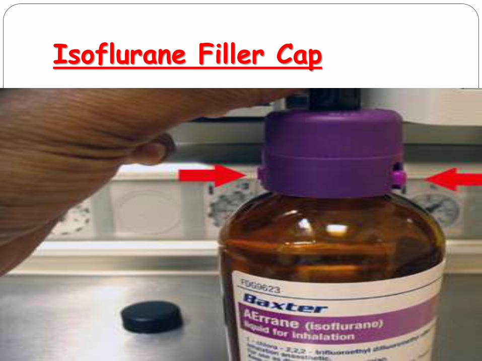
Isoflurane Filler Cap

Isoflurane Filler Cap

Isoflurane Filler Cap

Interlock Mechanism

Interlock Mechanism

Interlock Mechanism

Interlock Mechanism

Thank you