Embed Size (px)
Citation preview
INDEXVAPORIZERS
Ambient Vaporizers for Bulk Storage Tanks ............... 39A 7-8Dual Switch Vaporizer Switch Over........................... 39A-20Liquid Cylinder Ambient Vaporizer ............................... 39A-4ThermafinTM SupergapTM
Ambient Vaporizer................ 39A 5-6Mega-Fin Ambient Air Vaporizer ......................... 39A-9Carbon Dioxide Ambient Air Vaporizers........ 39A 10-12Propane Ambient Air Vaporizer ......................... 39A-10 Electric Vaporizer..................... 39A-15Electric Gas Trim Heater.......... 39A-16Electric Gas Heater .................. 39A-17Gas Cylinder Heater ................ 39A-17SF Cylinder Heater .................. 39A-17
HOSES, PIPING & THINGS
Bulk Tank Products .................. 39A-20Candy Cane Relief ................... 39A 18-19Cryogenic Check Valve............ 39A-20Composite Pipe for Compressed Gases – 3/4” and 1/2” I.D. .... 39A 21-24Duratec Valves......................... 39A-22Inert Brass Fittings .................. 39A-18Liquid Cylinder Regulator....... 39A-20Noise Reducing Vent............... 39A-20Oxygen Brass Fittings ............. 39A-19Pressure Reliefs........................ 39A 18-19Superflex Inert Cryogenic Liquid Cylinder Hoses........... 39A-18Superflex Oxygen Cryogenic Liquid Cylinder Hoses........... 39A-19
RATERMANNM A N U F A C T U R I N G , I N C .
1-800-264-7793www.rmiorder.com
Vaporizers at Work
VA
PO
RIZ
ER
S
39A
THIS TYPE OFVAPORIZER USES
NATURALCONVECTION
OF AIR TO
VAPORIZE LIQUEFIED GASES.
PressureBuildingAmbientVaporizersfor BulkStorageTanks
Rev: 7/11/17, 6/13/17
Many Vaporizers
IN STOCKReady to Ship the Same Day.
Ratermann Manufacturing, Inc. Customer Service 1-800-264-7793 � Fax 1-800-264-7797 � Order Online at Web Store www.rmiorder.com39A-2
VA
PO
RIZ
ER
S
Let us help youdesign and
engineer the installation of the
right vaporizingequipment for your
application andtemperature zone.
We can assist you withlarge and small vaporizerapplications across theUnited States, Canadaand Mexico.
Call us to
WORKwith you to
Design&Engineer
Rev: 10/10/17
Ratermann Manufacturing, Inc. Customer Service 1-800-264-7793 � Email [email protected] � Online at Web Store www.rmiorder.com 39A-3
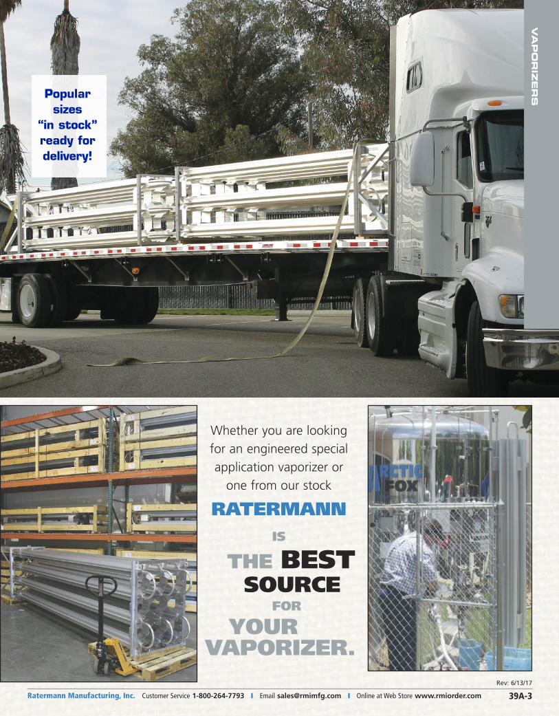
Whether you are looking
for an engineered special
application vaporizer or
one from our stock
RATERMANNIS
THE BESTSOURCE
FOR
YOUR VAPORIZER.
Popularsizes
“in stock”ready fordelivery!
VA
PO
RIZ
ER
S
Rev: 6/13/17
Ratermann Manufacturing, Inc. Customer Service 1-800-264-7793 � Fax 1-800-264-7797 � Order Online at Web Store www.rmiorder.com39A-4
VA
PO
RIZ
ER
S
† Part # LC-PAN2 is used with Part # FG00488 only. Does not fit Part # FG01312.** Please Note: This is Floor Mount/Free Standing only.
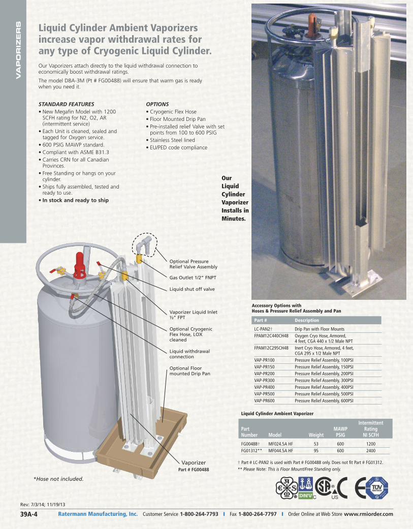
Our Vaporizers attach directly to the liquid withdrawal connection toeconomically boost withdrawal ratings.
The model D8A-3M (Pt # FG00488) will ensure that warm gas is readywhen you need it.
Liquid Cylinder Ambient Vaporizers increase vapor withdrawal rates forany type of Cryogenic Liquid Cylinder.
OPTIONS• Cryogenic Flex Hose• Floor Mounted Drip Pan• Pre-installed relief Valve with set
points from 100 to 600 PSIG• Stainless Steel lined• EU/PED code compliance
STANDARD FEATURES• New Megafin Model with 1200
SCFH rating for N2, O2, AR (intermittent service)
• Each Unit is cleaned, sealed andtagged for Oxygen service.
• 600 PSIG MAWP standard.• Compliant with ASME B31.3• Carries CRN for all Canadian
Provinces.• Free Standing or hangs on your
cylinder.• Ships fully assembled, tested and
ready to use.• In stock and ready to ship
Our Liquid CylinderVaporizer Installs inMinutes.
*Hose not included.
Accessory Options with Hoses & Pressure Relief Assembly and Pan
Part # Description
LC-PAN2† Drip Pan with Floor MountsFPAM12C440CH48 Oxygen Cryo Hose, Armored, 4 feet, CGA 440 x 1/2 Male NPTFPAM12C295CH48 Inert Cryo Hose, Armored, 4 feet, CGA 295 x 1/2 Male NPTVAP-PR100 Pressure Relief Assembly, 100PSIVAP-PR150 Pressure Relief Assembly, 150PSIVAP-PR200 Pressure Relief Assembly, 200PSIVAP-PR300 Pressure Relief Assembly, 300PSIVAP-PR400 Pressure Relief Assembly, 400PSIVAP-PR500 Pressure Relief Assembly, 500PSIVAP-PR600 Pressure Relief Assembly, 600PSI
Liquid Cylinder Ambient Vaporizer
IntermittentPart MAWP RatingNumber Model Weight PSIG NI SCFH
FG00488† MF024.5A�HF 53 600 1200FG01312** MF044.5A�HF 95 600 2400
Optional Pressure Relief Valve Assembly
Gas Outlet 1/2” FNPT
Liquid shut off valve
Vaporizer Liquid Inlet½” FPT
Optional CryogenicFlex Hose, LOXcleaned
Liquid withdrawalconnection
Optional Floormounted Drip Pan
VaporizerPart # FG00488
Rev: 7/3/14; 11/19/13
VA
PO
RIZ
ER
S
Ratermann Manufacturing, Inc. Customer Service 1-800-264-7793 � Email [email protected] � Online at Web Store www.rmiorder.com 39A-5
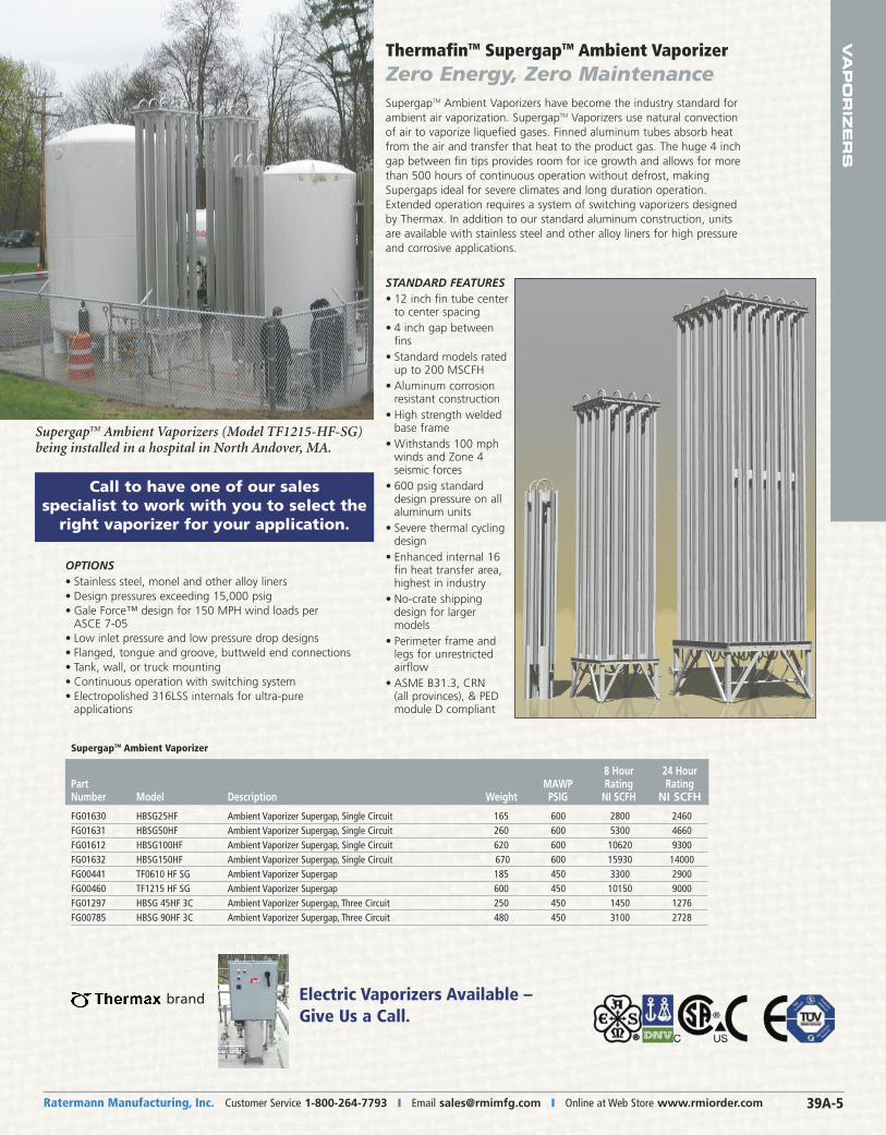
SupergapTM Ambient Vaporizers (Model TF1215-HF-SG)being installed in a hospital in North Andover, MA.
SupergapTM Ambient Vaporizers have become the industry standard forambient air vaporization. SupergapTM Vaporizers use natural convectionof air to vaporize liquefied gases. Finned aluminum tubes absorb heatfrom the air and transfer that heat to the product gas. The huge 4 inchgap between fin tips provides room for ice growth and allows for morethan 500 hours of continuous operation without defrost, making Supergaps ideal for severe climates and long duration operation.Extended operation requires a system of switching vaporizers designedby Thermax. In addition to our standard aluminum construction, unitsare available with stainless steel and other alloy liners for high pressureand corrosive applications.
OPTIONS• Stainless steel, monel and other alloy liners• Design pressures exceeding 15,000 psig• Gale Force™ design for 150 MPH wind loads per
ASCE 7-05• Low inlet pressure and low pressure drop designs• Flanged, tongue and groove, buttweld end connections• Tank, wall, or truck mounting• Continuous operation with switching system• Electropolished 316LSS internals for ultra-pure
applications
STANDARD FEATURES• 12 inch fin tube center
to center spacing• 4 inch gap between
fins• Standard models rated
up to 200 MSCFH• Aluminum corrosion
resistant construction• High strength welded
base frame• Withstands 100 mph
winds and Zone 4 seismic forces
• 600 psig standarddesign pressure on allaluminum units
• Severe thermal cyclingdesign
• Enhanced internal 16fin heat transfer area, highest in industry
• No-crate shippingdesign for larger models
• Perimeter frame andlegs for unrestricted airflow
• ASME B31.3, CRN (all provinces), & PED module D compliant
SupergapTM Ambient Vaporizer
8 Hour 24 HourPart MAWP Rating RatingNumber Model Description Weight PSIG NI SCFH NI SCFH
FG01630 HBSG25HF Ambient Vaporizer Supergap, Single Circuit 165 600 2800 2460FG01631 HBSG50HF Ambient Vaporizer Supergap, Single Circuit 260 600 5300 4660FG01612 HBSG100HF Ambient Vaporizer Supergap, Single Circuit 620 600 10620 9300FG01632 HBSG150HF Ambient Vaporizer Supergap, Single Circuit 670 600 15930 14000FG00441 TF0610�HF�SG Ambient Vaporizer Supergap 185 450 3300 2900FG00460 TF1215�HF�SG Ambient Vaporizer Supergap 600 450 10150 9000FG01297 HBSG�45HF�3C Ambient Vaporizer Supergap, Three Circuit 250 450 1450 1276FG00785 HBSG�90HF�3C Ambient Vaporizer Supergap, Three Circuit 480 450 3100 2728
Call to have one of our sales specialist to work with you to select theright vaporizer for your application.
Electric Vaporizers Available –Give Us a Call.
brand
ThermafinTM SupergapTM Ambient VaporizerZero Energy, Zero Maintenance
Ratermann Manufacturing, Inc. Customer Service 1-800-264-7793 � Fax 1-800-264-7797 � Order Online at Web Store www.rmiorder.com39A-6
VA
PO
RIZ
ER
S
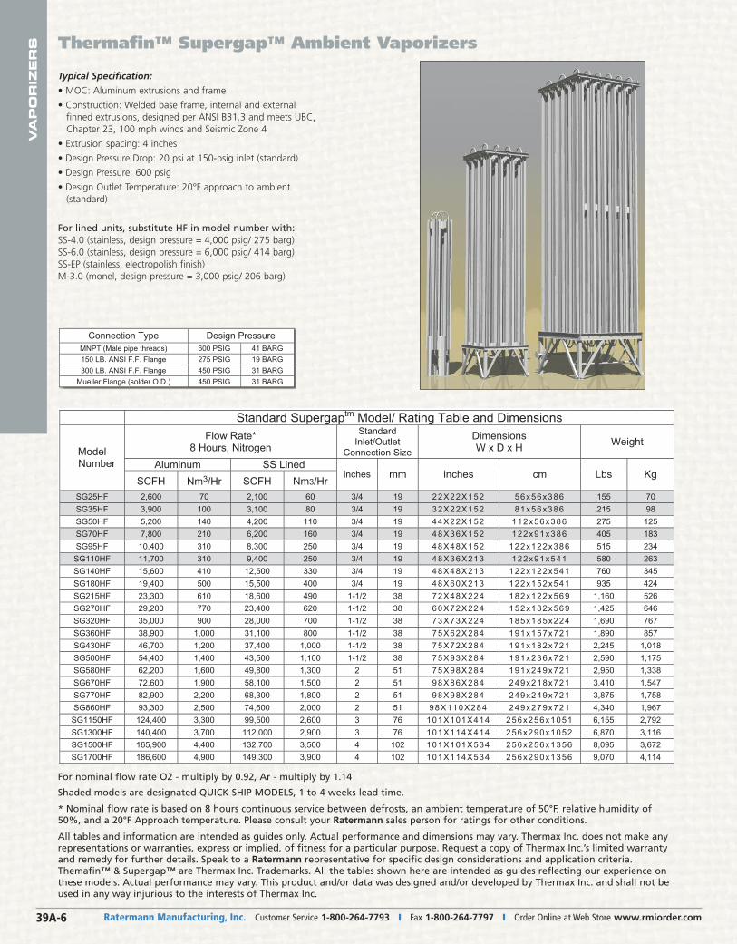
Standard Supergaptm Model/ Rating Table and Dimensions Flow Rate*
8 Hours, Nitrogen Standard
Inlet/OutletConnection Size
Dimensions W x D x H Weight
Aluminum SS Lined ModelNumber
SCFH Nm3/Hr SCFH Nm3/Hrinches mm inches cm Lbs Kg
SG25HF 2,600 70 2,100 60 3/4 19 22X22X152 56x56x386 155 70SG35HF 3,900 100 3,100 80 3/4 19 32X22X152 81x56x386 215 98SG50HF 5,200 140 4,200 110 3/4 19 44X22X 152 112x56x386 275 125 SG70HF 7,800 210 6,200 160 3/4 19 48X36X152 122x91x386 405 183SG95HF 10,400 310 8,300 250 3/4 19 48X48X 152 122x122x386 515 234
SG110HF 11,700 310 9,400 250 3/4 19 48X36X213 122x91x541 580 263SG140HF 15,600 410 12,500 330 3/4 19 48X48X213 122x122x541 760 345 SG180HF 19,400 500 15,500 400 3/4 19 48X60X213 122x152x541 935 424 SG215HF 23,300 610 18,600 490 1-1/2 38 72X48X224 182x122x569 1,160 526 SG270HF 29,200 770 23,400 620 1-1/2 38 60X72X224 152x182x569 1,425 646 SG320HF 35,000 900 28,000 700 1-1/2 38 73X73X224 185x185x224 1,690 767 SG360HF 38,900 1,000 31,100 800 1-1/2 38 75X62X284 191x157x721 1,890 857 SG430HF 46,700 1,200 37,400 1,000 1-1/2 38 75X72X284 191x182x721 2,245 1,018 SG500HF 54,400 1,400 43,500 1,100 1-1/2 38 75X93X284 191x236x721 2,590 1,175 SG580HF 62,200 1,600 49,800 1,300 2 51 75X98X284 191x249x721 2,950 1,338 SG670HF 72,600 1,900 58,100 1,500 2 51 98X86X284 249x218x721 3,410 1,547 SG770HF 82,900 2,200 68,300 1,800 2 51 98X98X284 249x249x721 3,875 1,758 SG860HF 93,300 2,500 74,600 2,000 2 51 98X110X 284 249x279x721 4,340 1,967
SG1150HF 124,400 3,300 99,500 2,600 3 76 101X101X414 256x256x1051 6,155 2,792 SG1300HF 140,400 3,700 112,000 2,900 3 76 101X114X414 256x290x1052 6,870 3,116 SG1500HF 165,900 4,400 132,700 3,500 4 102 101X101X534 256x256x1356 8,095 3,672 SG1700HF 186,600 4,900 149,300 3,900 4 102 101X114X534 256x290x1356 9,070 4,114
Connection Type Design PressureMNPT (Male pipe threads) 600 PSIG 41 BARG 150 LB. ANSI F.F. Flange 275 PSIG 19 BARG 300 LB. ANSI F.F. Flange 450 PSIG 31 BARG
Mueller Flange (solder O.D.) 450 PSIG 31 BARG
Thermafin™ Supergap™ Ambient Vaporizers
Typical Specification:
• MOC: Aluminum extrusions and frame
• Construction: Welded base frame, internal and externalfinned extrusions, designed per ANSI B31.3 and meets UBC,Chapter 23, 100 mph winds and Seismic Zone 4
• Extrusion spacing: 4 inches
• Design Pressure Drop: 20 psi at 150-psig inlet (standard)
• Design Pressure: 600 psig
• Design Outlet Temperature: 20°F approach to ambient (standard)
For lined units, substitute HF in model number with:SS-4.0 (stainless, design pressure = 4,000 psig/ 275 barg)SS-6.0 (stainless, design pressure = 6,000 psig/ 414 barg)SS-EP (stainless, electropolish finish)M-3.0 (monel, design pressure = 3,000 psig/ 206 barg)
For nominal flow rate O2 - multiply by 0.92, Ar - multiply by 1.14
Shaded models are designated QUICK SHIP MODELS, 1 to 4 weeks lead time.
* Nominal flow rate is based on 8 hours continuous service between defrosts, an ambient temperature of 50°F, relative humidity of50%, and a 20°F Approach temperature. Please consult your Ratermann sales person for ratings for other conditions.
All tables and information are intended as guides only. Actual performance and dimensions may vary. Thermax Inc. does not make anyrepresentations or warranties, express or implied, of fitness for a particular purpose. Request a copy of Thermax Inc.’s limited warrantyand remedy for further details. Speak to a Ratermann representative for specific design considerations and application criteria.Themafin™ & Supergap™ are Thermax Inc. Trademarks. All the tables shown here are intended as guides reflecting our experience onthese models. Actual performance may vary. This product and/or data was designed and/or developed by Thermax Inc. and shall not beused in any way injurious to the interests of Thermax Inc.
VA
PO
RIZ
ER
S
Ratermann Manufacturing, Inc. Customer Service 1-800-264-7793 � Email [email protected] � Online at Web Store www.rmiorder.com 39A-7
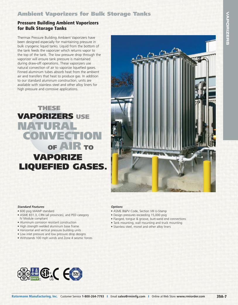
Pressure Building Ambient Vaporizersfor Bulk Storage Tanks
Thermax Pressure Building Ambient Vaporizers havebeen designed especially for maintaining pressure inbulk cryogenic liquid tanks. Liquid from the bottom ofthe tank feeds the vaporizer which returns vapor tothe top of the tank. The low pressure drop through thevaporizer will ensure tank pressure is maintained during draw-off operations. These vaporizers use natural convection of air to vaporize liquefied gases.Finned aluminum tubes absorb heat from the ambientair and transfers that heat to produce gas. In additionto our standard aluminum construction, units are available with stainless steel and other alloy liners forhigh pressure and corrosive applications.
Standard Features• 600 psig MAWP standard• ASME B31.3, CRN (all provinces), and PED category
IV Module compliant• Aluminum corrosion resistant construction• High strength welded aluminum base frame• Horizontal and vertical pressure building units• Low inlet pressure and low pressure drop designs• Withstands 100 mph winds and Zone 4 seismic forces
Options• ASME B&PV Code, Section VIII U-Stamp• Design pressures exceeding 15,000 psig• Flanged, tongue & groove, butt-weld end connections• Tank mounting, wall mounting and truck mounting• Stainless steel, monel and other alloy liners
Ambient Vaporizers for Bulk Storage Tanks
THESEVAPORIZERS USE
NATURALCONVECTION
OF AIR TO
VAPORIZE LIQUEFIED GASES.
Ratermann Manufacturing, Inc. Customer Service 1-800-264-7793 � Fax 1-800-264-7797 � Order Online at Web Store www.rmiorder.com39A-8
VA
PO
RIZ
ER
S Pressure Building Ambient Vaporizers for Bulk Storage Tanks
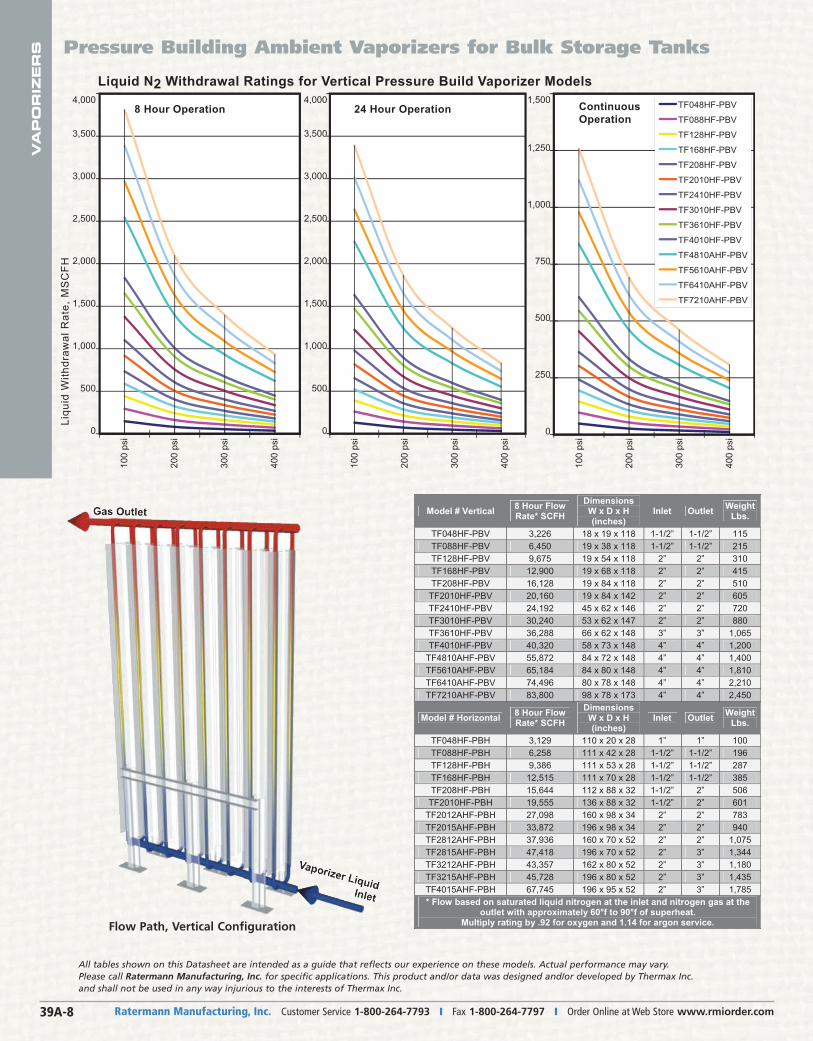
Liquid N2 Withdrawal Ratings for Vertical Pressure Build Vaporizer Models
8 Hour Operation
Liqu
id W
ithdr
awal
Rat
e, M
SC
FH
24 Hour Operation4,000
0
3,500
3,000
2,500
2,000
1,500
1,000
500
TF048HF-PBV
TF088HF-PBV
TF128HF-PBV
TF168HF-PBV
TF208HF-PBV
TF2010HF-PBV
TF2410HF-PBV
TF3010HF-PBV
TF3610HF-PBV
TF4010HF-PBV
TF4810AHF-PBV
TF5610AHF-PBV
TF6410AHF-PBV
TF7210AHF-PBV
ContinuousOperation
0
1,250
1,000
750
1,500
250
500
4,000
0
3,500
3,000
2,500
2,000
1,500
1,000
500
100
psi
400
psi
200
psi
300
psi
100
psi
400
psi
200
psi
300
psi
100
psi
400
psi
200
psi
300
psi
All tables shown on this Datasheet are intended as a guide that reflects our experience on these models. Actual performance may vary.Please call Ratermann Manufacturing, Inc. for specific applications. This product and/or data was designed and/or developed by Thermax Inc.and shall not be used in any way injurious to the interests of Thermax Inc.
Flow Path, Vertical Configuration
Model # Vertical 8 Hour Flow Rate* SCFH
Dimensions W x D x H (inches)
Inlet Outlet WeightLbs.
TF048HF-PBV 3,226 18 x 19 x 118 1-1/2” 1-1/2” 115TF088HF-PBV 6,450 19 x 38 x 118 1-1/2” 1-1/2” 215TF128HF-PBV 9,675 19 x 54 x 118 2” 2” 310TF168HF-PBV 12,900 19 x 68 x 118 2” 2” 415TF208HF-PBV 16,128 19 x 84 x 118 2” 2” 510
TF2010HF-PBV 20,160 19 x 84 x 142 2” 2” 605TF2410HF-PBV 24,192 45 x 62 x 146 2” 2” 720TF3010HF-PBV 30,240 53 x 62 x 147 2” 2” 880TF3610HF-PBV 36,288 66 x 62 x 148 3” 3” 1,065TF4010HF-PBV 40,320 58 x 73 x 148 4” 4” 1,200
TF4810AHF-PBV 55,872 84 x 72 x 148 4” 4” 1,400TF5610AHF-PBV 65,184 84 x 80 x 148 4” 4” 1,810TF6410AHF-PBV 74,496 80 x 78 x 148 4” 4” 2,210TF7210AHF-PBV 83,800 98 x 78 x 173 4” 4” 2,450
Model # Horizontal 8 Hour Flow Rate* SCFH
Dimensions W x D x H (inches)
Inlet Outlet WeightLbs.
TF048HF-PBH 3,129 110 x 20 x 28 1” 1” 100TF088HF-PBH 6,258 111 x 42 x 28 1-1/2” 1-1/2” 196TF128HF-PBH 9,386 111 x 53 x 28 1-1/2” 1-1/2” 287TF168HF-PBH 12,515 111 x 70 x 28 1-1/2” 1-1/2” 385TF208HF-PBH 15,644 112 x 88 x 32 1-1/2” 2” 506
TF2010HF-PBH 19,555 136 x 88 x 32 1-1/2” 2” 601TF2012AHF-PBH 27,098 160 x 98 x 34 2” 2” 783TF2015AHF-PBH 33,872 196 x 98 x 34 2” 2” 940TF2812AHF-PBH 37,936 160 x 70 x 52 2” 2” 1,075TF2815AHF-PBH 47,418 196 x 70 x 52 2” 3” 1,344TF3212AHF-PBH 43,357 162 x 80 x 52 2” 3” 1,180TF3215AHF-PBH 45,728 196 x 80 x 52 2” 3” 1,435TF4015AHF-PBH 67,745 196 x 95 x 52 2” 3” 1,785* Flow based on saturated liquid nitrogen at the inlet and nitrogen gas at the
outlet with approximately 60°f to 90°f of superheat. Multiply rating by .92 for oxygen and 1.14 for argon service.
VA
PO
RIZ
ER
S
Ratermann Manufacturing, Inc. Customer Service 1-800-264-7793 � Email [email protected] � Online at Web Store www.rmiorder.com 39A-9
City Mean
Max. Air Temp.
MeanMin. Air Temp.
Houston, TX 70°F 25°FJacksonville, FL 70°F 25°FFt. Worth, TX 65°F 15°FAtlanta, GA 65°F 15°FRaleigh, NC 60°F 10°FOklahoma City, KS 60°F 10°FKansas City, KS 55°F 0°FChicago, IL 50°F -5°FPittsburg, PA 50°F -10°FGreen Bay, MI 45°F -15°FDuluth, MN 40°F -25°FMontreal, QC 50°F 5°FEdmonton, AB 45°F -5°F
CityMean
Max. AirTemp.
MeanMin. AirTemp.
Houston, TX 70°F 25°FJacksonville, FL 70°F 25°FFt. Worth, TX 65°F 15°FAtlanta, GA 65°F 15°FRaleigh, NC 60°F 10°FOklahoma City, KS 60°F 10°FKansas City, KS 55°F 0°FChicago, IL 50°F -5°FPittsburg, PA 50°F -10°FGreen Bay, MI 45°F -15°FDuluth, MN 40°F -25°FMontreal, QC 50°F 5°FEdmonton, AB 45°F -5°F
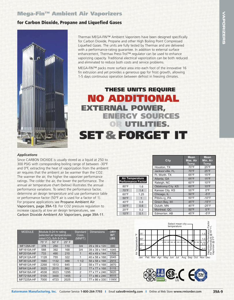
Mega-FinTM Ambient Air Vaporizers
for Carbon Dioxide, Propane and Liquefied Gases
ApplicationsSince CARBON DIOXIDE is usually stored as a liquid at 250 to300 PSIG with corresponding boiling range of between -30°Fand 0°F, extracting the heat of vaporization from the ambientair requires that the ambient air be warmer than the CO2.The warmer the air, the higher the vaporizer performance ratings. The colder the air, the lower the performance. Theannual air temperature chart (below) illustrates the annualperformance variations. To select the performance factor,determine air design temperature and use performance tableor performance factor (50°F air is used for a factor of 1). For propane applications see Propane Ambient AirVaporizers, page 39A-13. For CO2 pressure regulation toincrease capacity at low air design temperatures, see Carbon Dioxide Ambient Air Vaporizers, page 39A-11.
Thermax MEGA-FIN™ Ambient Vaporizers have been designed specificallyfor Carbon Dioxide, Propane and other High Boiling Point CompressedLiquefied Gases. The units are fully tested by Thermax and are deliveredwith a performance-rating guarantee. In addition to external surfaceenhancement, Thermax Press-Trol™ regulator can be used to enhancevaporizing capacity. Traditional electrical vaporization can be both reducedand eliminated to reduce both costs and service problems.
MEGA-FIN™ packs more surface area into each foot of the innovative 16fin extrusion and yet provides a generous gap for frost growth, allowing1-5 days continuous operation between defrost in freezing climates.
Air Temperature Performance Factor 80°F 1.670°F 1.460°F 1.2550°F 140°F 0.830°F 0.620°F 0.210°F 0.1
Vapo
rizer
Per
form
ance
Fac
tor
Air
Tem
pera
ture
@ 5
0°=1
,Va
poriz
er @
0°F
Air
Tem
pera
ture
°F
Select mean city temperature
ceDnaJ NovOctSepAugJulJunMayAprMarFeb
0.0
0.5
1.0
1.5
0°
25°
50°
75°
Air
Tem
pera
ture
°F
Jan Fe
0°
25°
50°
75°
Vapo
rizer
Per
form
ance
Fac
tor
Air
Tem
pera
ture
@ 5
0°=1
,Va
poriz
er@
0°F
Select mean citytemperature
DecNovOctSepAugJulJunMayAprMareb
0.00
0.5
1.0
1.5selected air temperatures rated CO2 lb/h 8-24 hr
MODULE
75° F 50° F 25° F
StandardConn.
(MNPT)
Dimensions DRY WT.LBS.
MF128A-HF 378 250 110 3/4 29 x 39 x 120 680MF1610A-HF 588 392 168 3/4 39 x 39 x 144 1045MF2010A-HF 733 490 210 1 40 x 49 x 144 1705MF2412A-HF 1128 755 322 1 40 x 58 x 168 2045MF3612A-HF 1680 1132 488 1 1/2 58 x 58 x 168 2915MF4812A-HF 2268 1513 645 2 58 x 77 x 168 3870MF6412A-HF 3025 2015 862 2 77 x 77 x 168 5115MF6418A-HF 4538 3023 1295 2 77 x 77 x 246 5620MF7218A-HF 5105 3400 1455 2 77 x 86 x 246 8515MF7225A-HF 7000 4723 2025 2 77 x 86 x 330 11800
DRYWT.LBS.
6801045170520452915387051155620851511800
Module 8-24 hr rating
THESE UNITS REQUIRE
NO ADDITIONALEXTERNAL POWER,
ENERGY SOURCESOR UTILITIES.
SET&FORGET IT
Ratermann Manufacturing, Inc. Customer Service 1-800-264-7793 � Fax 1-800-264-7797 � Order Online at Web Store www.rmiorder.com39A-10
VA
PO
RIZ
ER
S
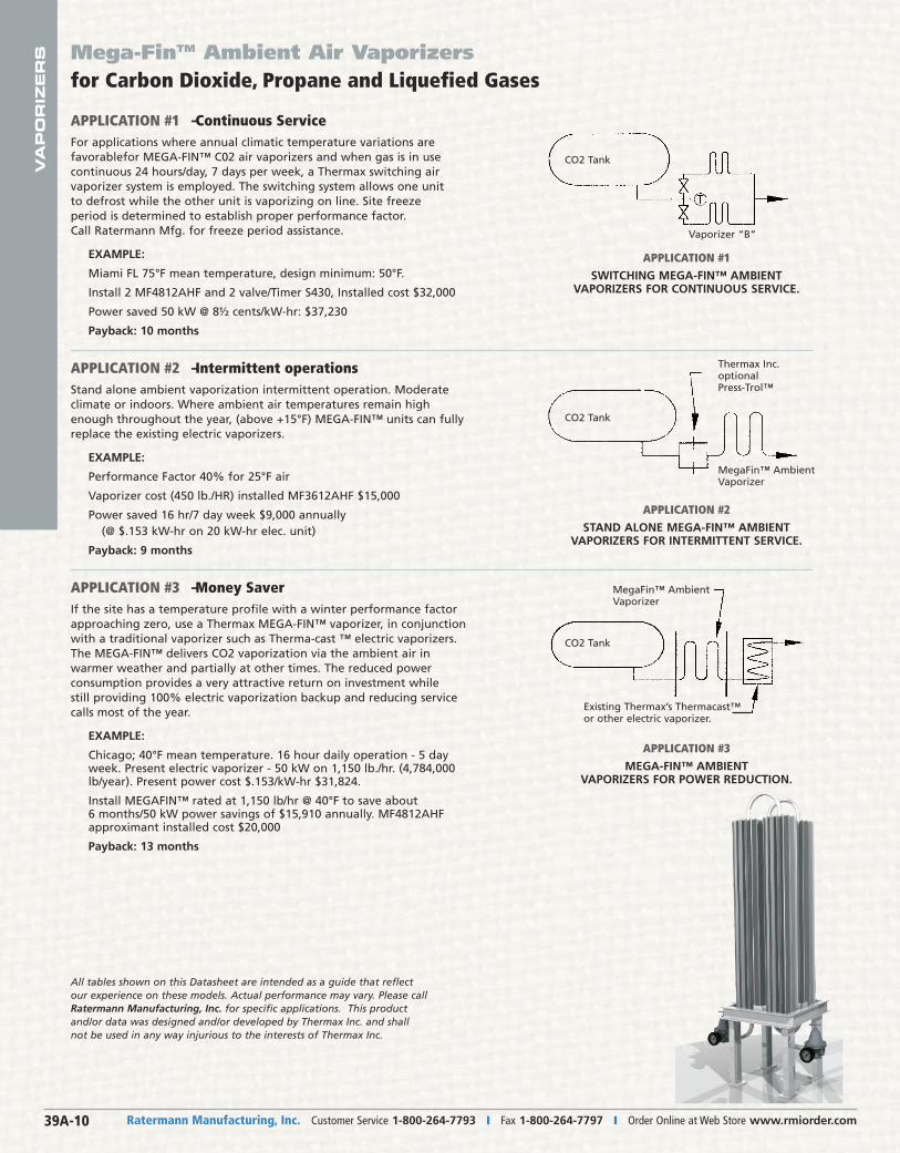
APPLICATION #1 – Continuous ServiceFor applications where annual climatic temperature variations arefavorablefor MEGA-FIN™ C02 air vaporizers and when gas is in usecontinuous 24 hours/day, 7 days per week, a Thermax switching airvaporizer system is employed. The switching system allows one unit to defrost while the other unit is vaporizing on line. Site freeze period is determined to establish proper performance factor. Call Ratermann Mfg. for freeze period assistance.
EXAMPLE:
Miami FL 75°F mean temperature, design minimum: 50°F.
Install 2 MF4812AHF and 2 valve/Timer S430, Installed cost $32,000
Power saved 50 kW @ 8½ cents/kW-hr: $37,230
Payback: 10 months
APPLICATION #2 – Intermittent operationsStand alone ambient vaporization intermittent operation. Moderateclimate or indoors. Where ambient air temperatures remain highenough throughout the year, (above +15°F) MEGA-FIN™ units can fullyreplace the existing electric vaporizers.
EXAMPLE:
Performance Factor 40% for 25°F air
Vaporizer cost (450 lb./HR) installed MF3612AHF $15,000
Power saved 16 hr/7 day week $9,000 annually (@ $.153 kW-hr on 20 kW-hr elec. unit)
Payback: 9 months
APPLICATION #3 – Money SaverIf the site has a temperature profile with a winter performance factorapproaching zero, use a Thermax MEGA-FIN™ vaporizer, in conjunctionwith a traditional vaporizer such as Therma-cast ™ electric vaporizers.The MEGA-FIN™ delivers CO2 vaporization via the ambient air inwarmer weather and partially at other times. The reduced power consumption provides a very attractive return on investment while still providing 100% electric vaporization backup and reducing servicecalls most of the year.
EXAMPLE:
Chicago; 40°F mean temperature. 16 hour daily operation - 5 dayweek. Present electric vaporizer - 50 kW on 1,150 lb./hr. (4,784,000lb/year). Present power cost $.153/kW-hr $31,824.
Install MEGAFIN™ rated at 1,150 lb/hr @ 40°F to save about 6 months/50 kW power savings of $15,910 annually. MF4812AHFapproximant installed cost $20,000
Payback: 13 months
Mega-FinTM Ambient Air Vaporizers for Carbon Dioxide, Propane and Liquefied Gases
All tables shown on this Datasheet are intended as a guide that reflectour experience on these models. Actual performance may vary. Please callRatermann Manufacturing, Inc. for specific applications. This productand/or data was designed and/or developed by Thermax Inc. and shallnot be used in any way injurious to the interests of Thermax Inc.
APPLICATION #1SWITCHING MEGA-FIN™ AMBIENT
VAPORIZERS FOR CONTINUOUS SERVICE.
APPLICATION #2STAND ALONE MEGA-FIN™ AMBIENT
VAPORIZERS FOR INTERMITTENT SERVICE.
APPLICATION #3MEGA-FIN™ AMBIENT
VAPORIZERS FOR POWER REDUCTION.
Existing Thermax’s Thermacast™or other electric vaporizer.
MegaFin™ Ambient Vaporizer
MegaFin™ Ambient Vaporizer
Thermax Inc.optionalPress-Trol™
Vaporizer “B”
CO2 Tank
CO2 Tank
CO2 Tank
VA
PO
RIZ
ER
S
Ratermann Manufacturing, Inc. Customer Service 1-800-264-7793 � Email [email protected] � Online at Web Store www.rmiorder.com 39A-11
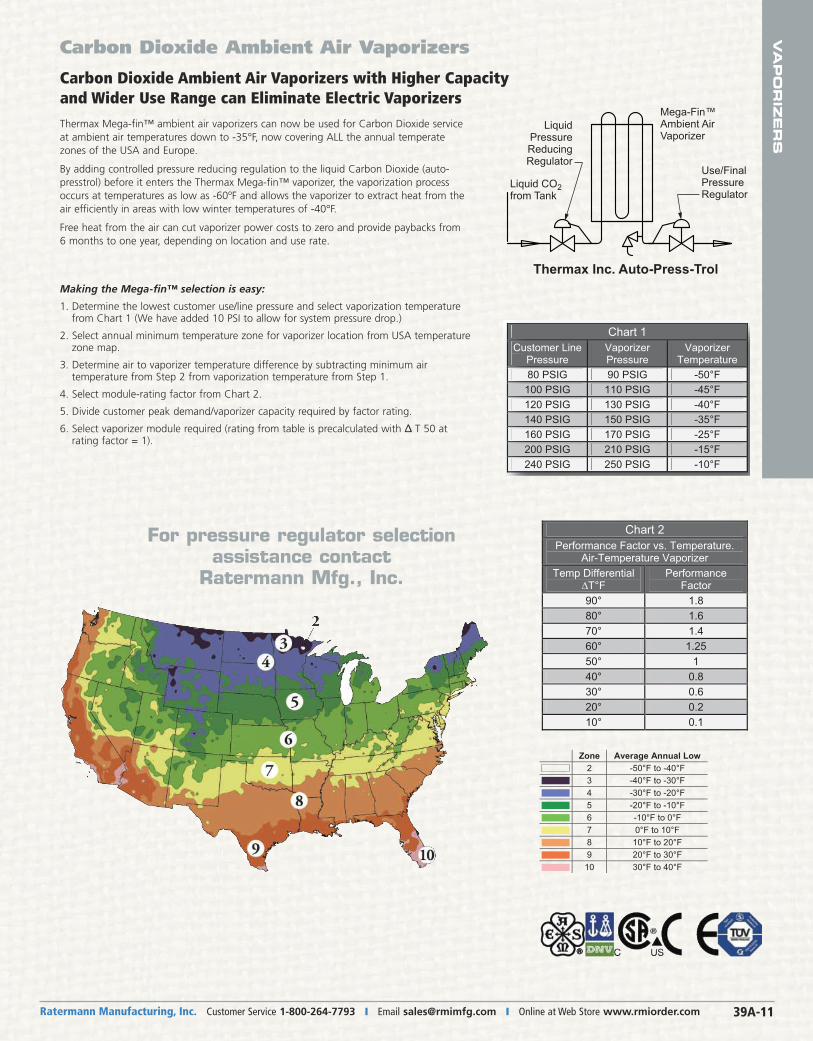
Carbon Dioxide Ambient Air Vaporizers with Higher Capacityand Wider Use Range can Eliminate Electric VaporizersThermax Mega-fin™ ambient air vaporizers can now be used for Carbon Dioxide serviceat ambient air temperatures down to -35°F, now covering ALL the annual temperatezones of the USA and Europe.
By adding controlled pressure reducing regulation to the liquid Carbon Dioxide (auto-presstrol) before it enters the Thermax Mega-fin™ vaporizer, the vaporization processoccurs at temperatures as low as -60ºF and allows the vaporizer to extract heat from theair efficiently in areas with low winter temperatures of -40°F.
Free heat from the air can cut vaporizer power costs to zero and provide paybacks from 6 months to one year, depending on location and use rate.
Making the Mega-fin™ selection is easy:
1. Determine the lowest customer use/line pressure and select vaporization temperaturefrom Chart 1 (We have added 10 PSI to allow for system pressure drop.)
2. Select annual minimum temperature zone for vaporizer location from USA temperaturezone map.
3. Determine air to vaporizer temperature difference by subtracting minimum air temperature from Step 2 from vaporization temperature from Step 1.
4. Select module-rating factor from Chart 2.
5. Divide customer peak demand/vaporizer capacity required by factor rating.
6. Select vaporizer module required (rating from table is precalculated with Δ�T 50 at rating factor = 1).
Carbon Dioxide Ambient Air Vaporizers
Zone Average Annual Low 2 -50°F to -40°F 3 -40°F to -30°F 4 -30°F to -20°F 5 -20°F to -10°F 6 -10°F to 0°F 7 0°F to 10°F 8 10°F to 20°F 9 20°F to 30°F 10 30°F to 40°F
Chart 2 Performance Factor vs. Temperature.
Air-Temperature Vaporizer Temp Differential
T°F Performance
Factor 90° 1.8 80° 1.6 70° 1.4 60° 1.25 50° 1 40° 0.8 30° 0.6 20° 0.2 10° 0.1
90 PSIG
Mega-Fin™Ambient AirVaporizer
Thermax Inc. Auto-Press-Trol
Use/FinalPressure Regulator
Liquid Pressure Reducing Regulator
Liquid CO2 from Tank
Z
90 PSIG
For pressure regulator selection assistance contact
Ratermann Mfg., Inc.
Chart 1 Customer Line
PressureVaporizer Pressure
Vaporizer Temperature
80 PSIG 90 PSIG -50°F 100 PSIG 110 PSIG -45°F 120 PSIG 130 PSIG -40°F 140 PSIG 150 PSIG -35°F 160 PSIG 170 PSIG -25°F 200 PSIG 210 PSIG -15°F 240 PSIG 250 PSIG -10°F
Te
Ratermann Manufacturing, Inc. Customer Service 1-800-264-7793 � Fax 1-800-264-7797 � Order Online at Web Store www.rmiorder.com39A-12
VA
PO
RIZ
ER
S Carbon Dioxide Ambient Air Vaporizers
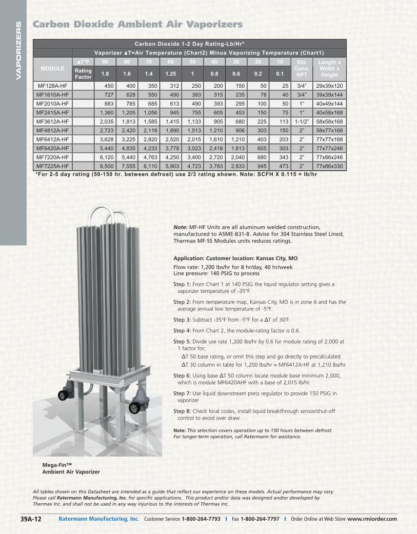
Carbon Dioxide 1-2 Day Rating-Lb/Hr* Vaporizer T=Air Temperature (Chart2) Minus Vaporizing Temperature (Chart1)
T°F 90 80 70 60 50 40 30 20 10 MODULE Rating
Factor 1.8 1.6 1.4 1.25 1 0.8 0.6 0.2 0.1
Std. Conn. NPT
Length x Width x Height
MF128A-HF 450 400 350 312 250 200 150 50 25 3/4” 29x39x120 MF1610A-HF 727 628 550 490 393 315 235 78 40 3/4” 39x39x144 MF2010A-HF 883 785 685 613 490 393 295 100 50 1” 40x49x144 MF2415A-HF 1,360 1,205 1,056 945 755 605 453 150 75 1” 40x58x168 MF3612A-HF 2,035 1,813 1,585 1,415 1,133 905 680 225 113 1-1/2” 58x58x168 MF4812A-HF 2,723 2,420 2,118 1,890 1,513 1.210 906 303 150 2” 58x77x168 MF6412A-HF 3,628 3,225 2,820 2,520 2,015 1,610 1,210 403 203 2” 77x77x168 MF6420A-HF 5,440 4,835 4,233 3,778 3,023 2,418 1,813 605 303 2” 77x77x246 MF7220A-HF 6,120 5,440 4,763 4,250 3,400 2,720 2,040 680 343 2” 77x86x246 MF7225A-HF 8,500 7,555 6,110 5,903 4,723 3,783 2,833 945 473 2” 77x86x330 *For 2-5 day rating (50-150 hr. between defrost) use 2/3 rating shown. Note: SCFH X 0.115 = lb/hr
Note: MF-HF Units are all aluminum welded construction, manufactured to ASME-B31-B. Advise for 304 Stainless Steel Lined,Thermax MF-SS Modules units reduces ratings.
Application: Customer location: Kansas City, MO
Flow rate: 1,200 lbs/hr for 8 hr/day, 40 hr/weekLine pressure: 140 PSIG to process
Step 1: From Chart 1 at 140 PSIG the liquid regulator setting gives avaporizer temperature of -35°F
Step 2: From temperature map, Kansas City, MO is in zone 6 and has theaverage annual low temperature of -5°F.
Step 3: Subtract -35°F from -5°F for a ΔT of 30˚F.
Step 4: From Chart 2, the module-rating factor is 0.6.
Step 5: Divide use rate 1,200 lbs/hr by 0.6 for module rating of 2,000 at1 factor for;
� ΔT 50 base rating, or omit this step and go directly to precalculated
� ΔT 30 column in table for 1,200 lbs/hr = MF6412A-HF at 1,210 lbs/hr.
Step 6: Using base ΔT 50 column locate module base minimum 2,000,which is module MF6420AHF with a base of 2,015 lb/hr.
Step 7: Use liquid downstream press regulator to provide 150 PSIG invaporizer
Step 8: Check local codes, install liquid breakthrough sensor/shut-off control to avoid over draw.
Note: This selection covers operation up to 150 hours between defrost. For longer-term operation, call Ratermann for assistance.
Mega-Fin™Ambient Air Vaporizer
All tables shown on this Datasheet are intended as a guide that reflect our experience on these models. Actual performance may vary.Please call Ratermann Manufacturing, Inc. for specific applications. This product and/or data was designed and/or developed byThermax Inc. and shall not be used in any way injurious to the interests of Thermax Inc.
VA
PO
RIZ
ER
S
Ratermann Manufacturing, Inc. Customer Service 1-800-264-7793 � Email [email protected] � Online at Web Store www.rmiorder.com 39A-13
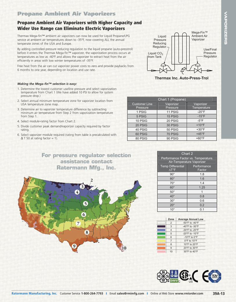
Propane Ambient Air Vaporizers with Higher Capacity andWider Use Range can Eliminate Electric VaporizersThermax Mega-fin™ ambient air vaporizers can now be used for Liquid Propane/LPG service at ambient air temperatures down to -35°F, now covering ALL the annual temperate zones of the USA and Europe.
By adding controlled pressure reducing regulation to the liquid propane (auto-presstrol)before it enters the Thermax Mega-fin™ vaporizer, the vaporization process occurs at temperatures as low as -40ºF and allows the vaporizer to extract heat from the air efficiently in areas with low winter temperatures of -35°F.
Free heat from the air can cut vaporizer power costs to zero and provide paybacks from 6 months to one year, depending on location and use rate.
Making the Mega-fin™ selection is easy:
1. Determine the lowest customer use/line pressure and select vaporizationtemperature from Chart 1 (We have added 10 PSI to allow for system pressure drop.)
2. Select annual minimum temperature zone for vaporizer location fromUSA temperature zone map.
3. Determine air to vaporizer temperature difference by subtracting minimum air temperature from Step 2 from vaporization temperaturefrom Step 1.
4. Select module-rating factor from Chart 2.
5. Divide customer peak demand/vaporizer capacity required by factor rating.
6. Select vaporizer module required (rating from table is precalculated with�T 50 at rating factor = 1).
Propane Ambient Air Vaporizers
Mega-Fin™Ambient AirVaporizer
Thermax Inc. Auto-Press-Trol
Use/FinalPressure Regulator
Liquid Pressure Reducing Regulator
Liquid CO2 from Tank
Z
90 PSIG
Zone Average Annual Low 2 -50°F to -40°F 3 -40°F to -30°F 4 -30°F to -20°F 5 -20°F to -10°F 6 -10°F to 0°F 7 0°F to 10°F 8 10°F to 20°F 9 20°F to 30°F 10 30°F to 40°F
Chart 2 Performance Factor vs. Temperature.
Air-Temperature Vaporizer Temp Differential
T°F Performance
Factor 90° 1.8 80° 1.6 70° 1.4 60° 1.25 50° 1 40° 0.8 30° 0.6 20° 0.2 10° 0.1
90 PSIG
For pressure regulator selection assistance contact
Ratermann Mfg., Inc.
Chart 1 (Propane) Customer Line
PressureVaporizer
Pressure 1 PSIG 11 PSIG 5 PSIG 15 PSIG 10 PSIG 20 PSIG 20 PSIG 30 PSIG 40 PSIG 50 PSIG 60 PSIG 70 PSIG 80 PSIG 90 PSIG
Vaporizer Temperature
-20°F -15°F -5°F
+10°F +30°F +45°F
+60°F
Ratermann Manufacturing, Inc. Customer Service 1-800-264-7793 � Fax 1-800-264-7797 � Order Online at Web Store www.rmiorder.com39A-14
VA
PO
RIZ
ER
S Propane Ambient Air Vaporizers
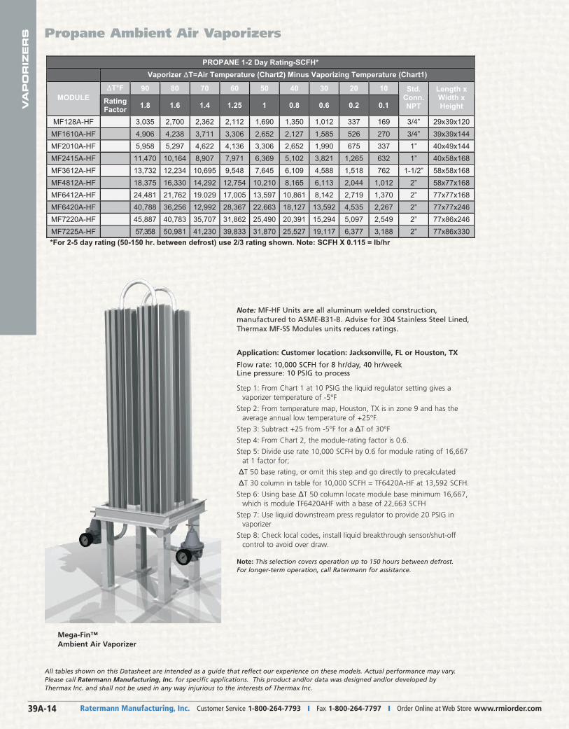
PROPANE 1-2 Day Rating-SCFH* Vaporizer ∆∆T=Air Temperature (Chart2) Minus Vaporizing Temperature (Chart1)
∆∆T°F 90 80 70 60 50 40 30 20 10MODULE Rating
Factor 1.8 1.6 1.4 1.25 1 0.8 0.6 0.2 0.1
Std.Conn. NPT
Length x Width x Height
MF128A-HF 3,035 2,700 2,362 2,112 1,690 1,350 1,012 337 169 3/4” 29x39x120 MF1610A-HF 4,906 4,238 3,711 3,306 2,652 2,127 1,585 526 270 3/4” 39x39x144 MF2010A-HF 5,958 5,297 4,622 4,136 3,306 2,652 1,990 675 337 1” 40x49x144 MF2415A-HF 11,470 10,164 8,907 7,971 6,369 5,102 3,821 1,265 632 1” 40x58x168 MF3612A-HF 13,732 12,234 10,695 9,548 7,645 6,109 4,588 1,518 762 1-1/2” 58x58x168 MF4812A-HF 18,375 16,330 14,292 12,754 10,210 8,165 6,113 2,044 1,012 2” 58x77x168 MF6412A-HF 24,481 21,762 19.029 17,005 13,597 10,861 8,142 2,719 1,370 2” 77x77x168 MF6420A-HF 40,788 36,256 12,992 28,367 22,663 18,127 13,592 4,535 2,267 2” 77x77x246 MF7220A-HF 45,887 40,783 35,707 31,862 25,490 20,391 15,294 5,097 2,549 2” 77x86x246 MF7225A-HF 57,358 50,981 41,230 39,833 31,870 25,527 19,117 6,377 3,188 2” 77x86x330 *For 2-5 day rating (50-150 hr. between defrost) use 2/3 rating shown. Note: SCFH X 0.115 = lb/hr
Note: MF-HF Units are all aluminum welded construction, manufactured to ASME-B31-B. Advise for 304 Stainless Steel Lined,Thermax MF-SS Modules units reduces ratings.
Application: Customer location: Jacksonville, FL or Houston, TX
Flow rate: 10,000 SCFH for 8 hr/day, 40 hr/weekLine pressure: 10 PSIG to process
Step 1: From Chart 1 at 10 PSIG the liquid regulator setting gives avaporizer temperature of -5°F
Step 2: From temperature map, Houston, TX is in zone 9 and has theaverage annual low temperature of +25°F.
Step 3: Subtract +25 from -5°F for a ΔT of 30°F
Step 4: From Chart 2, the module-rating factor is 0.6.
Step 5: Divide use rate 10,000 SCFH by 0.6 for module rating of 16,667at 1 factor for;
�ΔT 50 base rating, or omit this step and go directly to precalculated
�ΔT 30 column in table for 10,000 SCFH = TF6420A-HF at 13,592 SCFH.
Step 6: Using base ΔT 50 column locate module base minimum 16,667,which is module TF6420AHF with a base of 22,663 SCFH
Step 7: Use liquid downstream press regulator to provide 20 PSIG invaporizer
Step 8: Check local codes, install liquid breakthrough sensor/shut-off control to avoid over draw.
Note: This selection covers operation up to 150 hours between defrost. For longer-term operation, call Ratermann for assistance.
Mega-Fin™Ambient Air Vaporizer
All tables shown on this Datasheet are intended as a guide that reflect our experience on these models. Actual performance may vary.Please call Ratermann Manufacturing, Inc. for specific applications. This product and/or data was designed and/or developed byThermax Inc. and shall not be used in any way injurious to the interests of Thermax Inc.
VA
PO
RIZ
ER
S
Ratermann Manufacturing, Inc. Customer Service 1-800-264-7793 � Email [email protected] � Online at Web Store www.rmiorder.com 39A-15
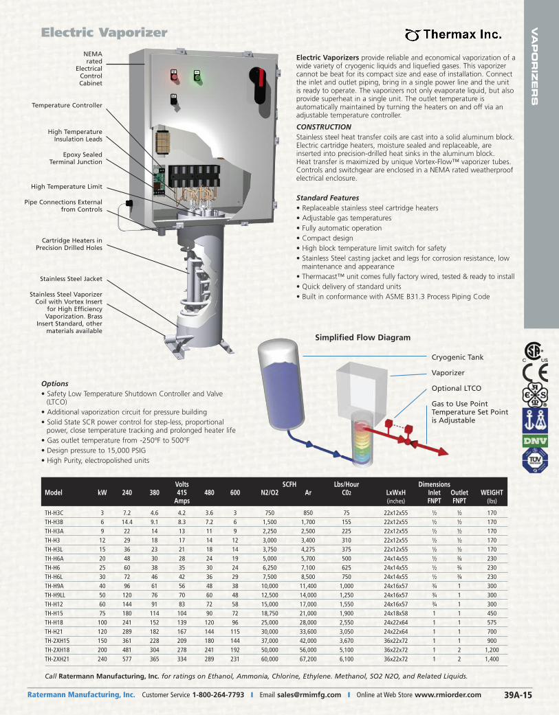
Electric Vaporizers provide reliable and economical vaporization of awide variety of cryogenic liquids and liquefied gases. This vaporizercannot be beat for its compact size and ease of installation. Connectthe inlet and outlet piping, bring in a single power line and the unitis ready to operate. The vaporizers not only evaporate liquid, but alsoprovide superheat in a single unit. The outlet temperature is automatically maintained by turning the heaters on and off via anadjustable temperature controller.
CONSTRUCTION Stainless steel heat transfer coils are cast into a solid aluminum block.Electric cartridge heaters, moisture sealed and replaceable, are inserted into precision-drilled heat sinks in the aluminum block. Heat transfer is maximized by unique Vortex-Flow™ vaporizer tubes. Controls and switchgear are enclosed in a NEMA rated weatherproofelectrical enclosure.
Options• Safety Low Temperature Shutdown Controller and Valve
(LTCO)• Additional vaporization circuit for pressure building• Solid State SCR power control for step-less, proportional
power, close temperature tracking and prolonged heater life• Gas outlet temperature from -250ºF to 500ºF• Design pressure to 15,000 PSIG• High Purity, electropolished units
Standard Features• Replaceable stainless steel cartridge heaters• Adjustable gas temperatures• Fully automatic operation• Compact design• High block temperature limit switch for safety• Stainless Steel casting jacket and legs for corrosion resistance, low
maintenance and appearance• Thermacast™ unit comes fully factory wired, tested & ready to install• Quick delivery of standard units• Built in conformance with ASME B31.3 Process Piping Code
Electric Vaporizer
Cryogenic Tank
Vaporizer
Optional LTCO
Gas to Use PointTemperature Set Pointis Adjustable
Simplified Flow Diagram
NEMArated
ElectricalControlCabinet
Temperature Controller
High Temperature Insulation Leads
Epoxy Sealed Terminal Junction
High Temperature Limit
Pipe Connections Externalfrom Controls
Cartridge Heaters in Precision Drilled Holes
Stainless Steel Jacket
Stainless Steel VaporizerCoil with Vortex Insert
for High Efficiency Vaporization. Brass
Insert Standard, other materials available
Volts SCFH Lbs/Hour DimensionsModel kW 240 380 415 480 600 N2/O2 Ar C02 LxWxH Inlet Outlet WEIGHT Amps (inches) FNPT FNPT (lbs)
TH-H3C 3 7.2 4.6 4.2 3.6 3 750 850 75 22x12x55 ½ ½ 170TH-H3B 6 14.4 9.1 8.3 7.2 6 1,500 1,700 155 22x12x55 ½ ½ 170TH-H3A 9 22 14 13 11 9 2,250 2,500 225 22x12x55 ½ ½ 170TH-H3 12 29 18 17 14 12 3,000 3,400 310 22x12x55 ½ ½ 170TH-H3L 15 36 23 21 18 14 3,750 4,275 375 22x12x55 ½ ½ 170TH-H6A 20 48 30 28 24 19 5,000 5,700 500 24x14x55 ½ ¾ 230TH-H6 25 60 38 35 30 24 6,250 7,100 625 24x14x55 ½ ¾ 230TH-H6L 30 72 46 42 36 29 7,500 8,500 750 24x14x55 ½ ¾ 230TH-H9A 40 96 61 56 48 38 10,000 11,400 1,000 24x16x57 ¾ 1 300TH-H9LL 50 120 76 70 60 48 12,500 14,000 1,250 24x16x57 ¾ 1 300TH-H12 60 144 91 83 72 58 15,000 17,000 1,550 24x16x57 ¾ 1 300TH-H15 75 180 114 104 90 72 18,750 21,000 1,900 24x18x58 1 1 450TH-H18 100 241 152 139 120 96 25,000 28,000 2,550 24x22x64 1 1 575TH-H21 120 289 182 167 144 115 30,000 33,600 3,050 24x22x64 1 1 700TH-2XH15 150 361 228 209 180 144 37,000 42,000 3,670 36x22x72 1 1 900TH-2XH18 200 481 304 278 241 192 50,000 56,000 5,100 36x22x72 1 2 1,200TH-2XH21 240 577 365 334 289 231 60,000 67,200 6,100 36x22x72 1 2 1,400
Call Ratermann Manufacturing, Inc. for ratings on Ethanol, Ammonia, Chlorine, Ethylene. Methanol, SO2 N2O, and Related Liquids.
Ratermann Manufacturing, Inc. Customer Service 1-800-264-7793 � Fax 1-800-264-7797 � Order Online at Web Store www.rmiorder.com39A-16
VA
PO
RIZ
ER
S
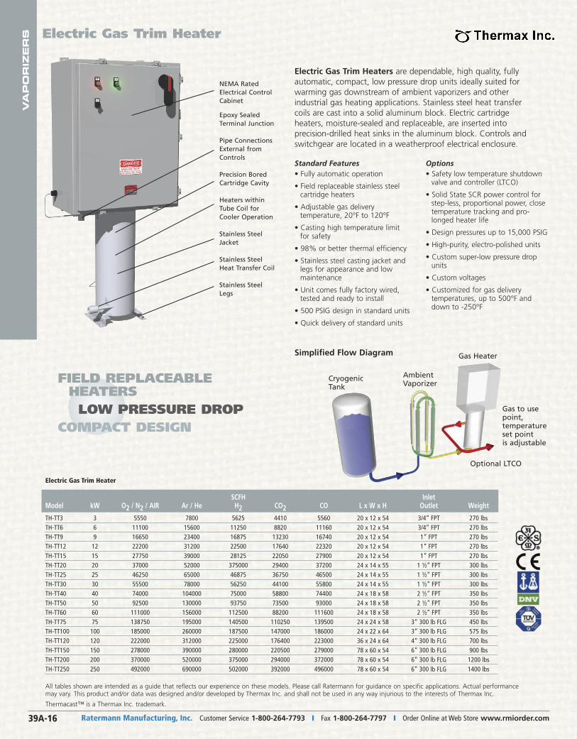
Electric Gas Trim Heaters are dependable, high quality, fullyautomatic, compact, low pressure drop units ideally suited forwarming gas downstream of ambient vaporizers and other industrial gas heating applications. Stainless steel heat transfercoils are cast into a solid aluminum block. Electric cartridgeheaters, moisture-sealed and replaceable, are inserted into precision-drilled heat sinks in the aluminum block. Controls andswitchgear are located in a weatherproof electrical enclosure.
Electric Gas Trim Heater
Options• Safety low temperature shutdown
valve and controller (LTCO)
• Solid State SCR power control forstep-less, proportional power, closetemperature tracking and pro-longed heater life
• Design pressures up to 15,000 PSIG
• High-purity, electro-polished units
• Custom super-low pressure dropunits
• Custom voltages
• Customized for gas delivery temperatures, up to 500°F anddown to -250°F
Standard Features• Fully automatic operation
• Field replaceable stainless steelcartridge heaters
• Adjustable gas delivery temperature, 20°F to 120°F
• Casting high temperature limitfor safety
• 98% or better thermal efficiency
• Stainless steel casting jacket andlegs for appearance and low maintenance
• Unit comes fully factory wired,tested and ready to install
• 500 PSIG design in standard units
• Quick delivery of standard units
NEMA RatedElectrical ControlCabinet
Epoxy SealedTerminal Junction
Pipe ConnectionsExternal fromControls
Precision BoredCartridge Cavity
Heaters withinTube Coil forCooler Operation
Stainless SteelJacket
Stainless SteelHeat Transfer Coil
Stainless SteelLegs
SCFH InletModel kW O2 / N2 / AIR Ar / He H2 CO2 CO L x W x H Outlet Weight
TH-TT3 3 5550 7800 5625 4410 5560 20 x 12 x 54 3/4” FPT 270 lbsTH-TT6 6 11100 15600 11250 8820 11160 20 x 12 x 54 3/4” FPT 270 lbsTH-TT9 9 16650 23400 16875 13230 16740 20 x 12 x 54 1” FPT 270 lbsTH-TT12 12 22200 31200 22500 17640 22320 20 x 12 x 54 1” FPT 270 lbsTH-TT15 15 27750 39000 28125 22050 27900 20 x 12 x 54 1” FPT 270 lbsTH-TT20 20 37000 52000 375000 29400 37200 24 x 14 x 55 1 ½” FPT 300 lbsTH-TT25 25 46250 65000 46875 36750 46500 24 x 14 x 55 1 ½” FPT 300 lbsTH-TT30 30 55500 78000 56250 44100 55800 24 x 14 x 55 1 ½” FPT 300 lbsTH-TT40 40 74000 104000 75000 58800 74400 24 x 18 x 58 2 ½” FPT 350 lbsTH-TT50 50 92500 130000 93750 73500 93000 24 x 18 x 58 2 ½” FPT 350 lbsTH-TT60 60 111000 156000 112500 88200 111600 24 x 18 x 58 2 ½” FPT 350 lbsTH-TT75 75 138750 195000 140500 110250 139500 24 x 24 x 58 3” 300 lb FLG 450 lbsTH-TT100 100 185000 260000 187500 147000 186000 24 x 22 x 64 3” 300 lb FLG 575 lbsTH-TT120 120 222000 312000 225000 176400 223000 36 x 24 x 64 4” 300 lb FLG 700 lbsTH-TT150 150 278000 390000 280000 220500 279000 78 x 60 x 54 6” 300 lb FLG 900 lbsTH-TT200 200 370000 520000 375000 294000 372000 78 x 60 x 54 6” 300 lb FLG 1200 lbsTH-TT250 250 492000 690000 502000 392000 496000 78 x 60 x 54 6” 300 lb FLG 1400 lbs
All tables shown are intended as a guide that reflects our experience on these models. Please call Ratermann for guidance on specific applications. Actual performancemay vary. This product and/or data was designed and/or developed by Thermax Inc. and shall not be used in any way injurious to the interests of Thermax Inc.
Thermacast™ is a Thermax Inc. trademark.
Electric Gas Trim Heater
CryogenicTank
AmbientVaporizer
Gas Heater
Optional LTCO
Gas to usepoint,temperatureset pointis adjustable
Simplified Flow Diagram
FIELD REPLACEABLE HEATERSLOW PRESSURE DROP
COMPACT DESIGN
VA
PO
RIZ
ER
S
Ratermann Manufacturing, Inc. Customer Service 1-800-264-7793 � Email [email protected] � Online at Web Store www.rmiorder.com 39A-17
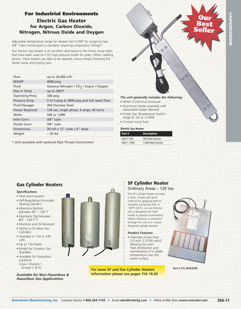
Adjustable temperature range for Heated Gas 5-200˚ for outgoing Gas.3/8” Tube Connections is standard, requiring compression fittings*.
Our Electric Gas Heater is an excellent alternative to the throw away stylesthat have been used on CO2 high pressure bottle for years. When needingservice, these heaters are able to be repaired, versus simply throwing theheater away and buying new.
* Unit available with optional Pipe Thread Connections
Flow up to 20,000 scfh
MAWP 4000 psig
Fluid Gaseous Nitrogen / CO2 / Argon / Oxygen
Rise in Temp up to 200°F
Operating Press 300 psig
Pressure Drop 3 to 5 psig at 3000 psig and full rated flow
Fluid Passages 304 Stainless Steel
Power Required 120 vac, single phase, 9 amps, 60 hertz
Watts 500 or 1,000
Inlet Conn. 3/8” tube
Outlet Conn. 3/8” tube
Dimensions 30 tall x 12” wide x 6” deep
Weight ~ 30 lbs.
Our Best Seller
For Industrial Environments
Electric Gas Heater for Argon, Carbon Dioxide,
Nitrogen, Nitrous Oxide and Oxygen
The unit generally includes the following:• NEMA 4 Electrical Enclosure• Aluminum heater assembly with
replaceable heater element• Outlet Gas Temperature Switch –
range of -50 to +1200F• Control circuit fuse
Specifications• Heat and Insulates• Self-Regulating Grounded
Heating Element• Maintains Bottom
between 90° - 130° F• Maintains Top between
80° - 120 F° F• Moisture and Oil Resistant• Ability to Fit Most Gas
Cylinders• Available in 120 or 240
volts• Up to 150 Watts• Model for Outdoor Use
Available• Available for Hazardous
Locations(Class I Division I Groups C & D)
The SF Cylinder Heater providesa clean, simple and quickmethod for applying heat tocylinders containing SF6. A130°F (54°C) cut-out thermo-stat is designed into eachheater to prevent overheating.Heater efficiency is improvedthrough the use of a customdesigned cylinder blanket.
Product Features• Operates at less than
2.0 w/in 2 (3100 w/m2 allowing for even heat distribution andmaintenance of a stabletemperature over theentire surface.
Available for Non-Hazardous &Hazardous Gas Applications
Part # CYL-SFHEATER
Gas Cylinder Heaters
For more SF and Gas Cylinder HeatersInformation please see pages 11A 19-20
SF Cylinder HeaterOrdinary Areas – 120 Vac
Part # Description
EGH-1-500 500 Watt VersionEGH-1-1000 1,000 Watt Version
Electric Gas Heater
Ratermann Manufacturing, Inc. Customer Service 1-800-264-7793 � Fax 1-800-264-7797 � Order Online at Web Store www.rmiorder.com39A-18
VA
PO
RIZ
ER
S
� MOST COMMON
� MOST COMMON
�
� Part # PR-CC295�
�
Part # Description
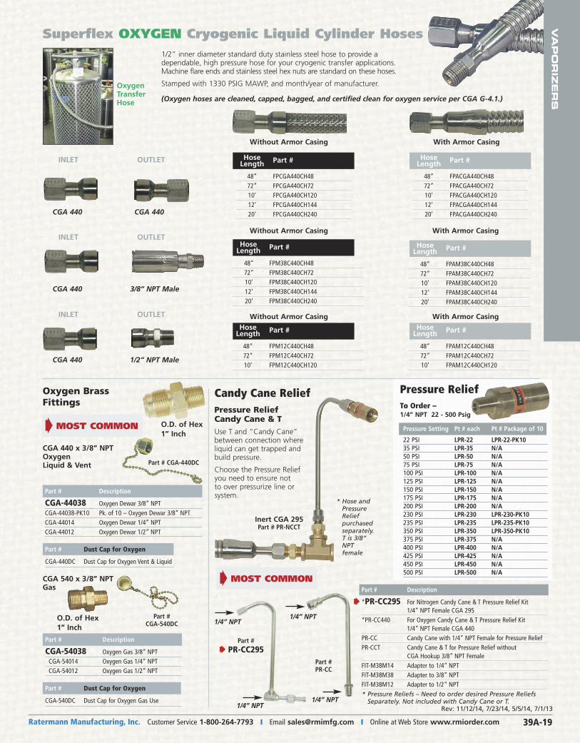
*PR-CC295 For Nitrogen Candy Cane & T Pressure Relief Kit 1/4” NPT Female CGA 295*PR-CC440 For Oxygen Candy Cane & T Pressure Relief Kit 1/4” NPT Female CGA 440PR-CC Candy Cane with 1/4” NPT Female for Pressure ReliefPR-CCT Candy Cane & T for Pressure Relief without CGA Hookup 3/8” NPT FemaleFIT-M38M14 Adapter to 1/4” NPTFIT-M38M38 Adapter to 3/8” NPTFIT-M38M12 Adapter to 1/2” NPT
* Pressure Reliefs – Need to order desired Pressure Reliefs Separately. Not included with Candy Cane or T.
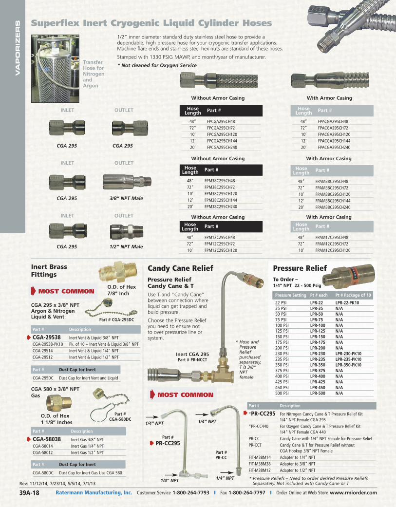
Superflex Inert Cryogenic Liquid Cylinder Hoses1/2” inner diameter standard duty stainless steel hose to provide adependable, high pressure hose for your cryogenic transfer applications.Machine flare ends and stainless steel hex nuts are standard of these hoses.
Stamped with 1330 PSIG MAWP, and month/year of manufacturer.
* Not cleaned for Oxygen ServiceTransferHose forNitrogenand Argon
INLET OUTLET
CGA 295
INLET OUTLET
CGA 295 3/8” NPT Male
INLET OUTLET
CGA 295 1/2” NPT Male
Hose Length Part #
48” FPCGA295CH48 72” FPCGA295CH72 10’ FPCGA295CH120 12’ FPCGA295CH144 20’ FPCGA295CH240
Hose Length Part #
48” FPACGA295CH48 72” FPACGA295CH72 10’ FPACGA295CH120 12’ FPACGA295CH144 20’ FPACGA295CH240
Without Armor Casing
Hose Length Part #
48” FPM38C295CH48 72” FPM38C295CH72 10’ FPM38C295CH120 12’ FPM38C295CH144 20’ FPM38C295CH240
Without Armor Casing
Hose Length Part #
48” FPAM38C295CH48 72” FPAM38C295CH72 10’ FPAM38C295CH120 12’ FPAM38C295CH144 20’ FPAM38C295CH240
With Armor Casing
Without Armor Casing With Armor Casing
With Armor Casing
CGA 295
Hose Length Part #
48” FPM12C295CH48 72” FPM12C295CH72 10’ FPM12C295CH120
Hose Length Part #
48” FPAM12C295CH48 72” FPAM12C295CH72 10’ FPAM12C295CH120
Part # PR-CC
1/4” NPT1/4” NPT
1/4” NPT 1/4” NPT
O.D. of Hex1 1/8” Inches
Part # Description
CGA-58038 Inert Gas 3/8” NPTCGA-58014 Inert Gas 1/4” NPTCGA-58012 Inert Gas 1/2” NPT
Part #CGA-580DC
Inert BrassFittings
CGA 295 x 3/8” NPTArgon & NitrogenLiquid & Vent
O.D. of Hex7/8” Inch
Part # CGA-295DC
Candy Cane ReliefPressure ReliefCandy Cane & T
Use T and “Candy Cane”between connection whereliquid can get trapped andbuild pressure.
Choose the Pressure Reliefyou need to ensure not to over pressurize line orsystem.
Inert CGA 295Part # PR-NCCT
* Hose andPressureRelief purchasedseparately.T is 3/8”NPTfemale
Pressure ReliefTo Order –1/4” NPT 22 - 500 Psig
Part # Description
CGA-29538 Inert Vent & Liquid 3/8” NPT CGA-29538-PK10 Pk. of 10 – Inert Vent & Liquid 3/8” NPT CGA-29514 Inert Vent & Liquid 1/4” NPTCGA-29512 Inert Vent & Liquid 1/2” NPT
Rev: 11/12/14, 7/23/14, 5/5/14, 7/1/13
Pressure Setting Pt # each Pt # Package of 10
22 PSI LPR-22 LPR-22-PK1035 PSI LPR-35 N/A50 PSI LPR-50 N/A75 PSI LPR-75 N/A100 PSI LPR-100 N/A125 PSI LPR-125 N/A150 PSI LPR-150 N/A175 PSI LPR-175 N/A200 PSI LPR-200 N/A230 PSI LPR-230 LPR-230-PK10235 PSI LPR-235 LPR-235-PK10 350 PSI LPR-350 LPR-350-PK10375 PSI LPR-375 N/A400 PSI LPR-400 N/A425 PSI LPR-425 N/A450 PSI LPR-450 N/A500 PSI LPR-500 N/A
Part # Dust Cap for Inert
CGA-580DC Dust Cap for Inert Gas Use CGA 580
Part # Dust Cap for Inert
CGA-295DC Dust Cap for Inert Vent and Liquid
CGA 580 x 3/8” NPTGas
Ratermann Manufacturing, Inc. Customer Service 1-800-264-7793 � Email [email protected] � Online at Web Store www.rmiorder.com 39A-19
Superflex OXYGEN Cryogenic Liquid Cylinder Hoses1/2” inner diameter standard duty stainless steel hose to provide adependable, high pressure hose for your cryogenic transfer applications.Machine flare ends and stainless steel hex nuts are standard on these hoses.
Stamped with 1330 PSIG MAWP, and month/year of manufacturer.
(Oxygen hoses are cleaned, capped, bagged, and certified clean for oxygen service per CGA G-4.1.)
OxygenTransferHose
INLET OUTLET
CGA 440
INLET OUTLET
CGA 440 3/8” NPT Male
INLET OUTLET
CGA 440 1/2” NPT Male
Hose Length Part #
48” FPCGA440CH48 72” FPCGA440CH72 10’ FPCGA440CH120 12’ FPCGA440CH144 20’ FPCGA440CH240
Hose Length Part #
48” FPACGA440CH48 72” FPACGA440CH72 10’ FPACGA440CH120 12’ FPACGA440CH144 20’ FPACGA440CH240
Without Armor Casing
Hose Length Part #
48” FPM38C440CH48 72” FPM38C440CH72 10’ FPM38C440CH120 12’ FPM38C440CH144 20’ FPM38C440CH240
Without Armor Casing
Hose Length Part #
48” FPAM38C440CH48 72” FPAM38C440CH72 10’ FPAM38C440CH120 12’ FPAM38C440CH144 20’ FPAM38C440CH240
With Armor Casing
Without Armor Casing
Hose Length Part #
48” FPAM12C440CH48 72” FPAM12C440CH72 10’ FPAM12C440CH120
With Armor Casing
With Armor Casing
CGA 440
Hose Length Part #
48” FPM12C440CH48 72” FPM12C440CH72 10’ FPM12C440CH120
VA
PO
RIZ
ER
S
� MOST COMMON
Part # PR-CC295�
Part # Description
*PR-CC295 For Nitrogen Candy Cane & T Pressure Relief Kit 1/4” NPT Female CGA 295*PR-CC440 For Oxygen Candy Cane & T Pressure Relief Kit 1/4” NPT Female CGA 440PR-CC Candy Cane with 1/4” NPT Female for Pressure ReliefPR-CCT Candy Cane & T for Pressure Relief without CGA Hookup 3/8” NPT FemaleFIT-M38M14 Adapter to 1/4” NPTFIT-M38M38 Adapter to 3/8” NPTFIT-M38M12 Adapter to 1/2” NPT
�
� MOST COMMON
Part # PR-CC
1/4” NPT1/4” NPT
1/4” NPT1/4” NPT
O.D. of Hex1” Inch
Part # Description
CGA-54038 Oxygen Gas 3/8” NPTCGA-54014 Oxygen Gas 1/4” NPTCGA-54012 Oxygen Gas 1/2” NPT
Part #CGA-540DC
Oxygen BrassFittings
CGA 440 x 3/8” NPTOxygenLiquid & Vent
O.D. of Hex1” Inch
Part # CGA-440DC
Candy Cane ReliefPressure ReliefCandy Cane & T
Use T and “Candy Cane”between connection whereliquid can get trapped andbuild pressure.
Choose the Pressure Reliefyou need to ensure not to over pressurize line orsystem.
Inert CGA 295Part # PR-NCCT
* Hose andPressureRelief purchasedseparately.T is 3/8”NPTfemale
CGA 540 x 3/8” NPTGas
Part # Description
CGA-44038 Oxygen Dewar 3/8” NPT CGA-44038-PK10 Pk. of 10 – Oxygen Dewar 3/8” NPT CGA-44014 Oxygen Dewar 1/4” NPTCGA-44012 Oxygen Dewar 1/2” NPT
Rev: 11/12/14, 7/23/14, 5/5/14, 7/1/13
Pressure ReliefTo Order –1/4” NPT 22 - 500 Psig
* Pressure Reliefs – Need to order desired Pressure Reliefs Separately. Not included with Candy Cane or T.
Pressure Setting Pt # each Pt # Package of 10
22 PSI LPR-22 LPR-22-PK1035 PSI LPR-35 N/A50 PSI LPR-50 N/A75 PSI LPR-75 N/A100 PSI LPR-100 N/A125 PSI LPR-125 N/A150 PSI LPR-150 N/A175 PSI LPR-175 N/A200 PSI LPR-200 N/A230 PSI LPR-230 LPR-230-PK10235 PSI LPR-235 LPR-235-PK10 350 PSI LPR-350 LPR-350-PK10375 PSI LPR-375 N/A400 PSI LPR-400 N/A425 PSI LPR-425 N/A450 PSI LPR-450 N/A500 PSI LPR-500 N/A
Part # Dust Cap for Oxygen
CGA-540DC Dust Cap for Oxygen Gas Use
Part # Dust Cap for Oxygen
CGA-440DC Dust Cap for Oxygen Vent & Liquid
Ratermann Manufacturing, Inc. Customer Service 1-800-264-7793 � Fax 1-800-264-7797 � Order Online at Web Store www.rmiorder.com39A-20
VA
PO
RIZ
ER
S
We Carry a HUGE INVENTORYof Cryogenic Valves – see 37C-J
ready to ship same day!
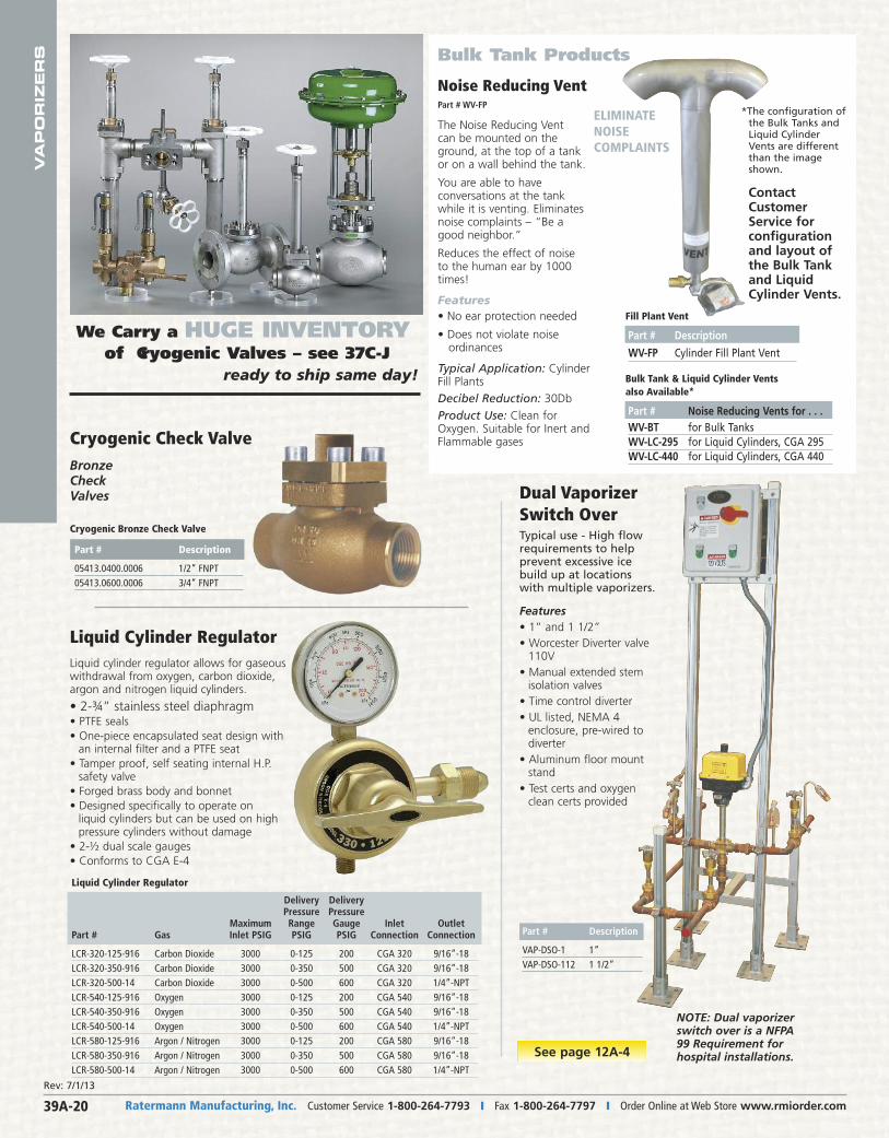
Part # Description
05413.0400.0006 1/2” FNPT05413.0600.0006 3/4” FNPT
Cryogenic Bronze Check Valve
Cryogenic Check ValveBronzeCheckValves
Liquid Cylinder Regulator
Liquid Cylinder Regulator
Delivery Delivery Pressure Pressure Maximum Range Gauge Inlet OutletPart # Gas Inlet PSIG PSIG PSIG Connection Connection
LCR-320-125-916 Carbon Dioxide 3000 0-125 200 CGA 320 9/16”-18LCR-320-350-916 Carbon Dioxide 3000 0-350 500 CGA 320 9/16”-18LCR-320-500-14 Carbon Dioxide 3000 0-500 600 CGA 320 1/4”-NPTLCR-540-125-916 Oxygen 3000 0-125 200 CGA 540 9/16”-18LCR-540-350-916 Oxygen 3000 0-350 500 CGA 540 9/16”-18LCR-540-500-14 Oxygen 3000 0-500 600 CGA 540 1/4”-NPTLCR-580-125-916 Argon / Nitrogen 3000 0-125 200 CGA 580 9/16”-18LCR-580-350-916 Argon / Nitrogen 3000 0-350 500 CGA 580 9/16”-18LCR-580-500-14 Argon / Nitrogen 3000 0-500 600 CGA 580 1/4”-NPT
Bulk Tank Products
Noise Reducing VentPart # WV-FP
The Noise Reducing Vent can be mounted on theground, at the top of a tankor on a wall behind the tank.
You are able to have conversations at the tankwhile it is venting. Eliminatesnoise complaints – “Be agood neighbor.”
Reduces the effect of noise to the human ear by 1000times!
Features • No ear protection needed
• Does not violate noise ordinances
Typical Application: CylinderFill Plants
Decibel Reduction: 30Db
Product Use: Clean forOxygen. Suitable for Inert andFlammable gases
ELIMINATENOISE COMPLAINTS
Fill Plant Vent
Bulk Tank & Liquid Cylinder Vents also Available*
Part # Noise Reducing Vents for . . . WV-BT for Bulk TanksWV-LC-295 for Liquid Cylinders, CGA 295WV-LC-440 for Liquid Cylinders, CGA 440
ContactCustomerService for configurationand layout ofthe Bulk Tankand LiquidCylinder Vents.
*The configuration ofthe Bulk Tanks andLiquid CylinderVents are differentthan the imageshown.
Part # Description
WV-FP Cylinder Fill Plant Vent
Liquid cylinder regulator allows for gaseouswithdrawal from oxygen, carbon dioxide,argon and nitrogen liquid cylinders.
• 2-¾” stainless steel diaphragm• PTFE seals• One-piece encapsulated seat design with
an internal filter and a PTFE seat• Tamper proof, self seating internal H.P.
safety valve• Forged brass body and bonnet• Designed specifically to operate on
liquid cylinders but can be used on highpressure cylinders without damage
• 2-½ dual scale gauges• Conforms to CGA E-4
See page 12A-4
NOTE: Dual vaporizerswitch over is a NFPA99 Requirement forhospital installations.
Dual VaporizerSwitch OverTypical use - High flowrequirements to help prevent excessive icebuild up at locationswith multiple vaporizers.
Part # Description
VAP-DSO-1 1”VAP-DSO-112 1 1/2”
Features • 1” and 1 1/2”• Worcester Diverter valve
110V• Manual extended stem
isolation valves• Time control diverter• UL listed, NEMA 4
enclosure, pre-wired todiverter
• Aluminum floor mountstand
• Test certs and oxygen clean certs provided
Rev: 7/1/13
Ratermann Manufacturing, Inc. Customer Service 1-800-264-7793 � Email [email protected] � Online at Web Store www.rmiorder.com 39A-21
VA
PO
RIZ
ER
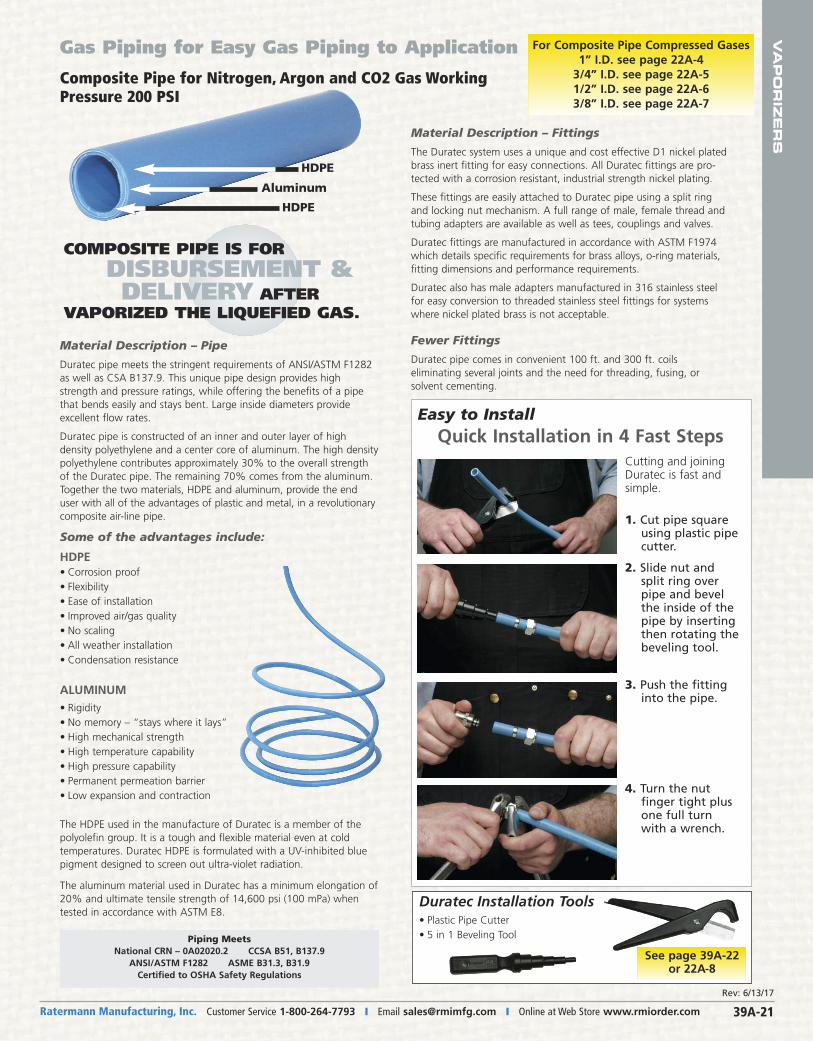
SGas Piping for Easy Gas Piping to Application
Material Description – Pipe
Duratec pipe meets the stringent requirements of ANSI/ASTM F1282as well as CSA B137.9. This unique pipe design provides highstrength and pressure ratings, while offering the benefits of a pipethat bends easily and stays bent. Large inside diameters provideexcellent flow rates.
Duratec pipe is constructed of an inner and outer layer of high density polyethylene and a center core of aluminum. The high densitypolyethylene contributes approximately 30% to the overall strengthof the Duratec pipe. The remaining 70% comes from the aluminum.Together the two materials, HDPE and aluminum, provide the enduser with all of the advantages of plastic and metal, in a revolutionary composite air-line pipe.
Some of the advantages include:
HDPE• Corrosion proof• Flexibility• Ease of installation• Improved air/gas quality• No scaling• All weather installation• Condensation resistance
ALUMINUM• Rigidity• No memory – “stays where it lays”• High mechanical strength• High temperature capability• High pressure capability• Permanent permeation barrier• Low expansion and contraction
Aluminum
HDPE
HDPE
Material Description – Fittings
The Duratec system uses a unique and cost effective D1 nickel platedbrass inert fitting for easy connections. All Duratec fittings are pro-tected with a corrosion resistant, industrial strength nickel plating.
These fittings are easily attached to Duratec pipe using a split ringand locking nut mechanism. A full range of male, female thread andtubing adapters are available as well as tees, couplings and valves.
Duratec fittings are manufactured in accordance with ASTM F1974which details specific requirements for brass alloys, o-ring materials,fitting dimensions and performance requirements.
Duratec also has male adapters manufactured in 316 stainless steelfor easy conversion to threaded stainless steel fittings for systemswhere nickel plated brass is not acceptable.
Fewer Fittings
Duratec pipe comes in convenient 100 ft. and 300 ft. coils eliminating several joints and the need for threading, fusing, or solvent cementing.
The HDPE used in the manufacture of Duratec is a member of the polyolefin group. It is a tough and flexible material even at cold temperatures. Duratec HDPE is formulated with a UV-inhibited bluepigment designed to screen out ultra-violet radiation.
The aluminum material used in Duratec has a minimum elongation of20% and ultimate tensile strength of 14,600 psi (100 mPa) whentested in accordance with ASTM E8.
Duratec Installation Tools• Plastic Pipe Cutter • 5 in 1 Beveling Tool
See page 39A-22or 22A-8
Piping MeetsNational CRN – 0A02020.2 CCSA B51, B137.9
ANSI/ASTM F1282 ASME B31.3, B31.9Certified to OSHA Safety Regulations
Cutting and joiningDuratec is fast andsimple.
1. Cut pipe squareusing plastic pipecutter.
2. Slide nut andsplit ring overpipe and bevelthe inside of thepipe by insertingthen rotating thebeveling tool.
3. Push the fittinginto the pipe.
4. Turn the nut finger tight plusone full turnwith a wrench.
Easy to InstallQuick Installation in 4 Fast Steps
Composite Pipe for Nitrogen, Argon and CO2 Gas WorkingPressure 200 PSI
COMPOSITE PIPE IS FOR DISBURSEMENT & DELIVERY AFTER
VAPORIZED THE LIQUEFIED GAS.
For Composite Pipe Compressed Gases 1” I.D. see page 22A-4
3/4” I.D. see page 22A-51/2” I.D. see page 22A-63/8” I.D. see page 22A-7
Rev: 6/13/17
Ratermann Manufacturing, Inc. Customer Service 1-800-264-7793 � Fax 1-800-264-7797 � Order Online at Web Store www.rmiorder.com39A-22
VA
PO
RIZ
ER
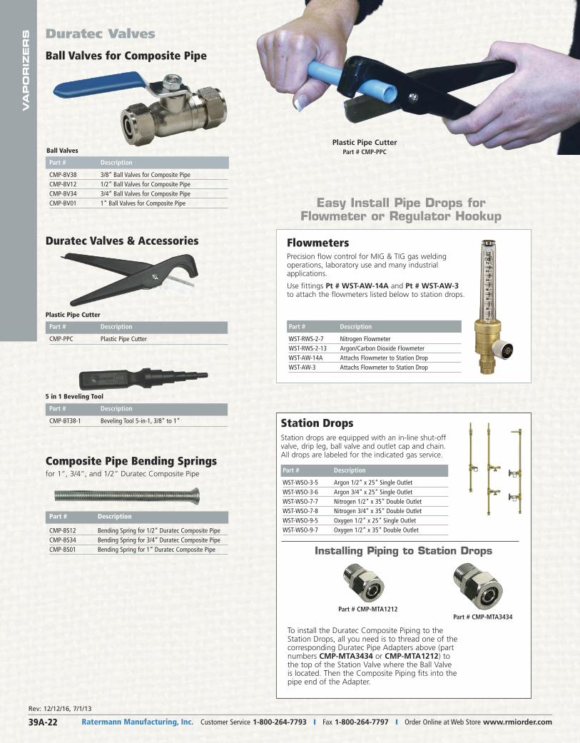
S Duratec Valves
Plastic Pipe CutterPart # CMP-PPC
Plastic Pipe Cutter
Part # Description
CMP-BT38-1 Beveling Tool 5-in-1, 3/8” to 1”
5 in 1 Beveling Tool
Station DropsStation drops are equipped with an in-line shut-offvalve, drip leg, ball valve and outlet cap and chain.All drops are labeled for the indicated gas service.
Part # Description
WST-WSO-3-5 Argon 1/2” x 25” Single OutletWST-WSO-3-6 Argon 3/4” x 25” Single OutletWST-WSO-7-7 Nitrogen 1/2” x 35” Double OutletWST-WSO-7-8 Nitrogen 3/4” x 35” Double OutletWST-WSO-9-5 Oxygen 1/2” x 25” Single OutletWST-WSO-9-7 Oxygen 1/2” x 35” Double Outlet
To install the Duratec Composite Piping to theStation Drops, all you need is to thread one of thecorresponding Duratec Pipe Adapters above (part numbers CMP-MTA3434 or CMP-MTA1212) tothe top of the Station Valve where the Ball Valveis located. Then the Composite Piping fits into thepipe end of the Adapter.
Installing Piping to Station Drops
FlowmetersPrecision flow control for MIG & TIG gas weldingoperations, laboratory use and many industrial applications.
Use fittings Pt # WST-AW-14A and Pt # WST-AW-3to attach the flowmeters listed below to station drops.
Composite Pipe Bending Springs
Duratec Valves & Accessories
for 1”, 3/4”, and 1/2” Duratec Composite Pipe
Part # Description
CMP-BS12 Bending Spring for 1/2” Duratec Composite PipeCMP-BS34 Bending Spring for 3/4” Duratec Composite PipeCMP-BS01 Bending Spring for 1” Duratec Composite Pipe
Ball Valves for Composite Pipe
Part # Description
CMP-PPC Plastic Pipe Cutter
Ball Valves
Part # Description
CMP-BV38 3/8” Ball Valves for Composite Pipe CMP-BV12 1/2” Ball Valves for Composite Pipe CMP-BV34 3/4” Ball Valves for Composite Pipe CMP-BV01 1” Ball Valves for Composite Pipe Easy Install Pipe Drops for
Flowmeter or Regulator Hookup
Part # Description
WST-RWS-2-7 Nitrogen FlowmeterWST-RWS-2-13 Argon/Carbon Dioxide FlowmeterWST-AW-14A Attachs Flowmeter to Station DropWST-AW-3 Attachs Flowmeter to Station Drop
Part # CMP-MTA3434Part # CMP-MTA1212
Rev: 12/12/16, 7/1/13
Ratermann Manufacturing, Inc. Customer Service 1-800-264-7793 � Email [email protected] � Online at Web Store www.rmiorder.com 39A-23
VA
PO
RIZ
ER
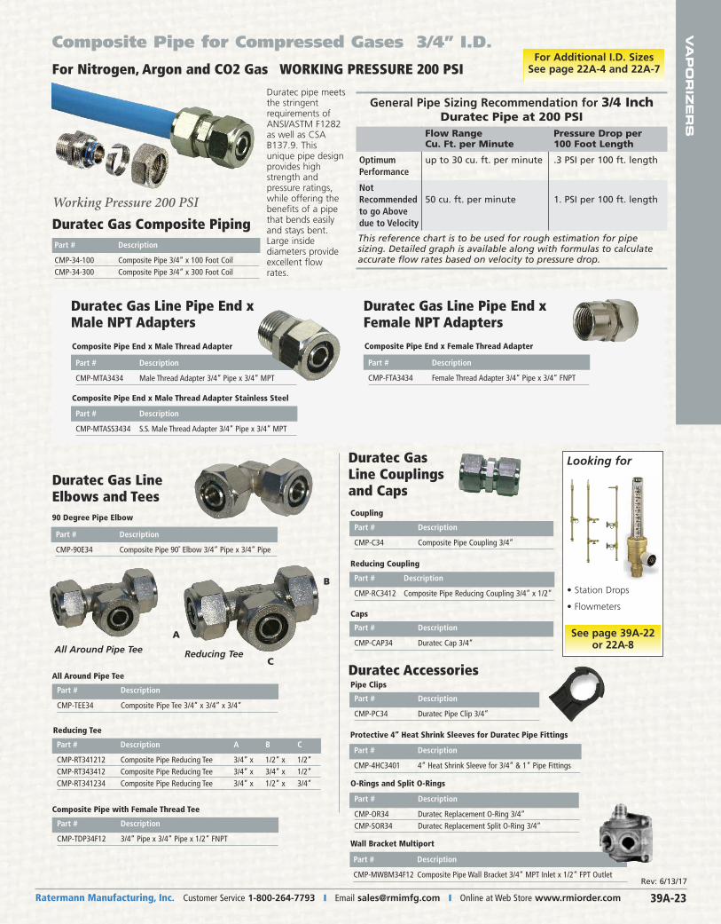
SComposite Pipe for Compressed Gases 3/4” I.D.
For Nitrogen, Argon and CO2 Gas WORKING PRESSURE 200 PSI
Wall Bracket Multiport
Part # Description
CMP-4HC3401 4” Heat Shrink Sleeve for 3/4” & 1” Pipe Fittings
Protective 4” Heat Shrink Sleeves for Duratec Pipe Fittings
Working Pressure 200 PSI
Duratec pipe meetsthe stringentrequirements ofANSI/ASTM F1282as well as CSAB137.9. Thisunique pipe designprovides highstrength and pressure ratings,while offering thebenefits of a pipethat bends easilyand stays bent.Large inside diameters provideexcellent flowrates.
This reference chart is to be used for rough estimation for pipe sizing. Detailed graph is available along with formulas to calculateaccurate flow rates based on velocity to pressure drop.
General Pipe Sizing Recommendation for 3/4 InchDuratec Pipe at 200 PSI
Flow Range Pressure Drop per Cu. Ft. per Minute 100 Foot Length
Optimum up to 30 cu. ft. per minute .3 PSI per 100 ft. lengthPerformance
Not Recommended 50 cu. ft. per minute 1. PSI per 100 ft. lengthto go Abovedue to VelocityDuratec Gas Composite Piping
Part # Description
CMP-34-100 Composite Pipe 3/4” x 100 Foot CoilCMP-34-300 Composite Pipe 3/4” x 300 Foot Coil
Part # Description
CMP-MTA3434 Male Thread Adapter 3/4” Pipe x 3/4” MPT
Composite Pipe End x Male Thread Adapter
Part # Description
CMP-MTASS3434 S.S. Male Thread Adapter 3/4” Pipe x 3/4” MPT
Composite Pipe End x Male Thread Adapter Stainless Steel
Duratec Gas Line Pipe End x Male NPT Adapters
Part # Description
CMP-FTA3434 Female Thread Adapter 3/4” Pipe x 3/4” FNPT
Composite Pipe End x Female Thread Adapter
Duratec Gas Line Pipe End xFemale NPT Adapters
Part # Description
CMP-90E34 Composite Pipe 90˚ Elbow 3/4” Pipe x 3/4” Pipe
90 Degree Pipe Elbow
Duratec Gas LineElbows and Tees
All Around Pipe Tee
Part # Description A B C
CMP-RT341212 Composite Pipe Reducing Tee 3/4” x 1/2” x 1/2”CMP-RT343412 Composite Pipe Reducing Tee 3/4” x 3/4” x 1/2”CMP-RT341234 Composite Pipe Reducing Tee 3/4” x 1/2” x 3/4”
Reducing Tee
Part # Description
CMP-C34 Composite Pipe Coupling 3/4”
Coupling
Caps
Part # Description
CMP-PC34 Duratec Pipe Clip 3/4”
Pipe Clips
Part # Description
CMP-OR34 Duratec Replacement O-Ring 3/4”CMP-SOR34 Duratec Replacement Split O-Ring 3/4”
O-Rings and Split O-Rings
Reducing Coupling
Duratec GasLine Couplingsand Caps
Duratec Accessories
A
C
B
All Around Pipe Tee Reducing Tee
• Station Drops
• Flowmeters
Looking for
See page 39A-22or 22A-8
Part # Description
CMP-TEE34 Composite Pipe Tee 3/4” x 3/4” x 3/4”
Composite Pipe with Female Thread Tee
Part # Description
CMP-TDP34F12 3/4” Pipe x 3/4” Pipe x 1/2” FNPT
Part # Description
CMP-RC3412 Composite Pipe Reducing Coupling 3/4” x 1/2”
Part # Description
CMP-CAP34 Duratec Cap 3/4”
For Additional I.D. Sizes See page 22A-4 and 22A-7
Rev: 6/13/17
Part # Description
CMP-MWBM34F12 Composite Pipe Wall Bracket 3/4” MPT Inlet x 1/2” FPT Outlet
Ratermann Manufacturing, Inc. Customer Service 1-800-264-7793 � Fax 1-800-264-7797 � Order Online at Web Store www.rmiorder.com39A-24
VA
PO
RIZ
ER
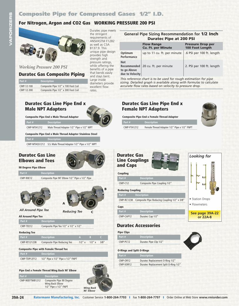
S Composite Pipe for Compressed Gases 1/2” I.D.
Part # Description
CMP-90EFTWB1212 Composite Pipe 90 Degree Wing Back Elbow 1/2” Pipe x 1/2” FNPT
Pipe End x Female Thread Wing Back 90˚ Elbow
Wing Back90˚ Elbow
Part # Description
CMP-TDP12F12 1/2” Pipe x 1/2” Pipe x 1/2” FNPT
Composite Pipe with Female Thread Tee
This reference chart is to be used for rough estimation for pipe sizing. Detailed graph is available along with formulas to calculateaccurate flow rates based on velocity to pressure drop.
General Pipe Sizing Recommendation for 1/2 InchDuratec Pipe at 200 PSI
Flow Range Pressure Drop per Cu. Ft. per Minute 100 Foot Length
Optimum up to 11 cu. ft. per minute .6 PSI per 100 ft. lengthPerformance
Not Recommended 20 cu. ft. per minute 2. PSI per 100 ft. lengthto go Abovedue to Velocity
Part # Description
CMP-MTA1212 Male Thread Adapter 1/2” Pipe x 1/2” MPT
Composite Pipe End x Male Thread Adapter
Part # Description
CMP-MTASS1212 S.S. Male Thread Adapter 1/2” Pipe x 1/2” MPT
Composite Pipe End x Male Thread Adapter Stainless Steel
Part # Description
CMP-90E12 Composite Pipe 90˚ Elbow 1/2” Pipe x 1/2” Pipe
90 Degree Pipe Elbow
Duratec Gas Line Pipe End x Male NPT Adapters
Part # Description
CMP-FTA1212 Female Thread Adapter 1/2” Pipe x 1/2” FNPT
Composite Pipe End x Female Thread Adapter
Duratec Gas Line Pipe End xFemale NPT Adapters
Duratec Gas LineElbows and Tees
All Around Pipe Tee
Part # Description A B C
CMP-RT121238 Composite Pipe Reducing Tee 1/2” x 1/2” x 3/8”
Reducing Tee
Part # Description
CMP-C12 Composite Pipe Coupling 1/2”
Coupling
Caps
Part # Description
CMP-PC12 Duratec Pipe Clip 1/2”
Pipe Clips
Part # Description
CMP-OR12 Duratec Replacement O-Ring 1/2”CMP-SOR12 Duratec Replacement Split O-Ring 1/2”
O-Rings and Split O-Rings
Reducing Coupling
Duratec GasLine Couplingsand Caps
Duratec Accessories
A
C
B
All Around Pipe Tee Reducing Tee
• Station Drops
• Flowmeters
Looking for
See page 39A-22or 22A-8
Part # Description
CMP-TEE12 Composite Pipe Tee 1/2” x 1/2” x 1/2”
Part # Description
CMP-RC1238 Composite Pipe Reducing Coupling 1/2” x 3/8”
Part # Description
CMP-CAP12 Duratec Cap 1/2”
For Nitrogen, Argon and CO2 Gas WORKING PRESSURE 200 PSI
Working Pressure 200 PSI
Duratec pipe meetsthe stringentrequirements ofANSI/ASTM F1282as well as CSAB137.9. Thisunique pipe designprovides highstrength and pressure ratings,while offering thebenefits of a pipethat bends easilyand stays bent.Large inside diameters provideexcellent flowrates.
Duratec Gas Composite Piping Part # Description
CMP-12-100 Composite Pipe 1/2” x 100 Foot CoilCMP-12-300 Composite Pipe 1/2” x 300 Foot Coil

VA
PO
RIZ
ER
S
Ratermann Manufacturing, Inc. Customer Service 1-800-264-7793 � Email [email protected] � Online at Web Store www.rmiorder.com 39A-25
NEWPRODUCTSNEWPRODUCTScomingsoon
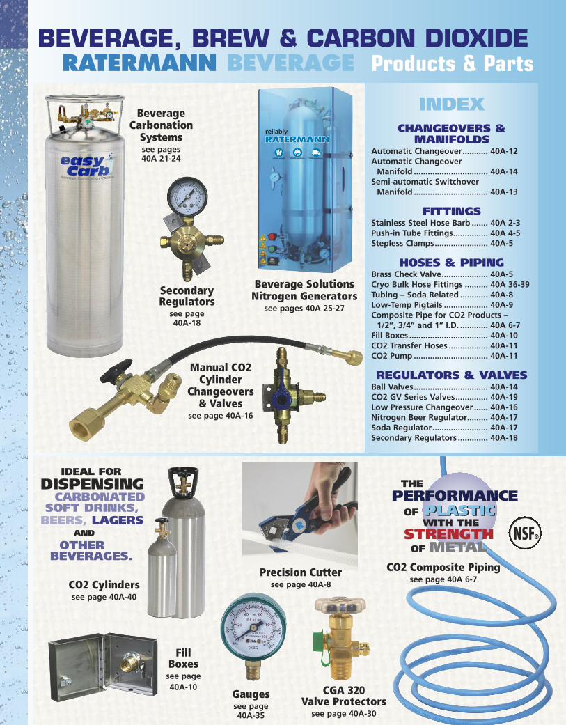
CO2 Composite Pipingsee page 40A 6-7
PLASTIC
METAL
THE PERFORMANCEOF PLASTIC
WITH THESTRENGTHOF METAL
NSF®
BEVERAGE, BREW & CARBON DIOXIDERATERMANN BEVERAGE Products & Parts
R
Precision Cuttersee page 40A-8
Manual CO2Cylinder
Changeovers & Valves
see page 40A-16
IDEAL FORDISPENSINGCARBONATED
SOFT DRINKS,BEERS, LAGERS
AND
OTHER BEVERAGES.
FillBoxes
see page40A-10
INDEXCHANGEOVERS &
MANIFOLDSAutomatic Changeover........... 40A-12Automatic Changeover Manifold ................................ 40A-14Semi-automatic Switchover Manifold ................................ 40A-13
FITTINGSStainless Steel Hose Barb ....... 40A 2-3Push-in Tube Fittings............... 40A 4-5Stepless Clamps....................... 40A-5
HOSES & PIPING Brass Check Valve.................... 40A-5Cryo Bulk Hose Fittings .......... 40A 36-39Tubing – Soda Related ............ 40A-8Low-Temp Pigtails ................... 40A-9Composite Pipe for CO2 Products – 1/2”, 3/4” and 1” I.D. ............ 40A 6-7Fill Boxes .................................. 40A-10CO2 Transfer Hoses ................. 40A-11CO2 Pump ................................ 40A-11
REGULATORS & VALVES Ball Valves................................ 40A-14CO2 GV Series Valves.............. 40A-19Low Pressure Changeover ...... 40A-16Nitrogen Beer Regulator......... 40A-17Soda Regulator........................ 40A-17Secondary Regulators ............. 40A-18
Gaugessee page 40A-35
CGA 320Valve Protectors
see page 40A-30
SecondaryRegulators
see page 40A-18
Beverage SolutionsNitrogen Generators
see pages 40A 25-27
Beverage CarbonationSystemssee pages 40A 21-24
CO2 Cylinderssee page 40A-40