Embed Size (px)
Citation preview

Fixed Functional Appliances
1
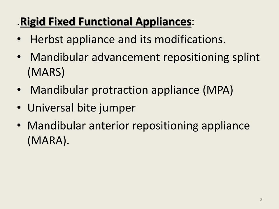
.Rigid Fixed Functional Appliances:
• Herbst appliance and its modifications.
• Mandibular advancement repositioning splint (MARS)
• Mandibular protraction appliance (MPA)
• Universal bite jumper
• Mandibular anterior repositioning appliance (MARA).
2
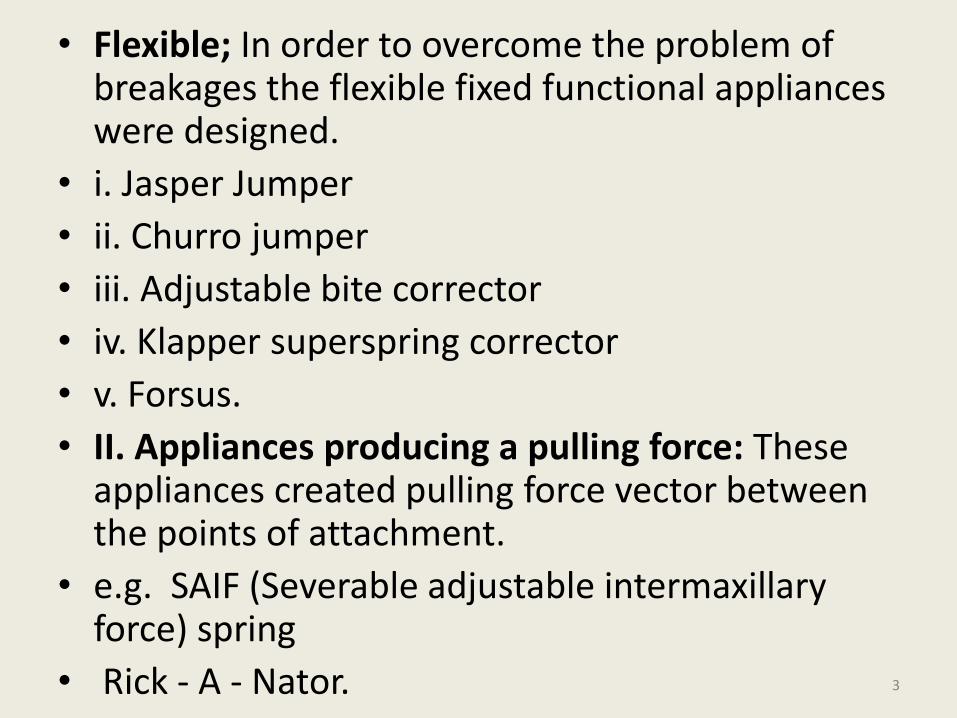
• Flexible; In order to overcome the problem of breakages the flexible fixed functional appliances were designed.
• i. Jasper Jumper
• ii. Churro jumper
• iii. Adjustable bite corrector
• iv. Klapper superspring corrector
• v. Forsus.
• II. Appliances producing a pulling force: These appliances created pulling force vector between the points of attachment.
• e.g. SAIF (Severable adjustable intermaxillary force) spring
• Rick - A - Nator. 3
• The term “FUNCTIONAL APPLIANCE” refers to a variety of mainly removable appliances designed to alter the arrangements of various muscle groups that influence the function and position of mandible in order to transmit forces to the dentition and basal bone.
• Typically, these muscular forces to the dentition and basal bone are generated by altering the mandibular position sagittallyand vertically resulting orthodontic changes.
4
The term “Fixed Functional Appliances” literally means a functional appliance that
is fixed to the upper and lower jaws.
5
Rise of Fixed Functional Appliances:
• In order to understand this phenomenalpopularity of these fixed functional appliances,one has to look at the drawbacks of theconventional removable appliances :-
• The results of treatment are totally dependanton patient cooperation.
• The appliances are indicated in “actively”growing individuals only
6
• Mouth breathers sometimes experience considerable difficulty in adapting to these intraoral appliances
• Large size, unstable fixation, lack of tactile sensibility, exert pressure on mucosa (encouraging gingivitis), reduce space for tongue causes difficulties in deglutition & speech & often affects aesthetic appearance.
• These adverse effects make the adaptation & acceptance of these appliance more difficult.
7
• The fixed functional appliances can be used in post adolescent patients who have passed maximal pubertal growth and may be too old for functional appliances.
• The fixed functional appliances permit utilization of the residual growth in such post adolescent patients.
• Less dependence on patient co-operation
• Works all 24hrs a day
8
• Treatment time is reduced
• They are smaller in size permitting better adaptation to functions such as a mastication, swallowing, speech and breathing.
• Along with the above advantages, the fact that these appliances are used along with the conventional fixed appliance make them an attractive proposition for the orthodontist.
9

10
Classification
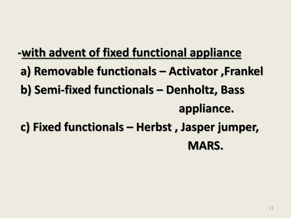
-with advent of fixed functional appliance
a) Removable functionals – Activator ,Frankel
b) Semi-fixed functionals – Denholtz, Bass
appliance.
c) Fixed functionals – Herbst , Jasper jumper,
MARS.
11
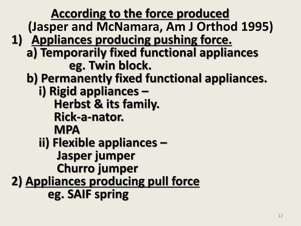
According to the force produced(Jasper and McNamara, Am J Orthod 1995)
1) Appliances producing pushing force.a) Temporarily fixed functional appliances
eg. Twin block. b) Permanently fixed functional appliances.
i) Rigid appliances –Herbst & its family.Rick-a-nator.MPA
ii) Flexible appliances –Jasper jumperChurro jumper
2) Appliances producing pull forceeg. SAIF spring
12
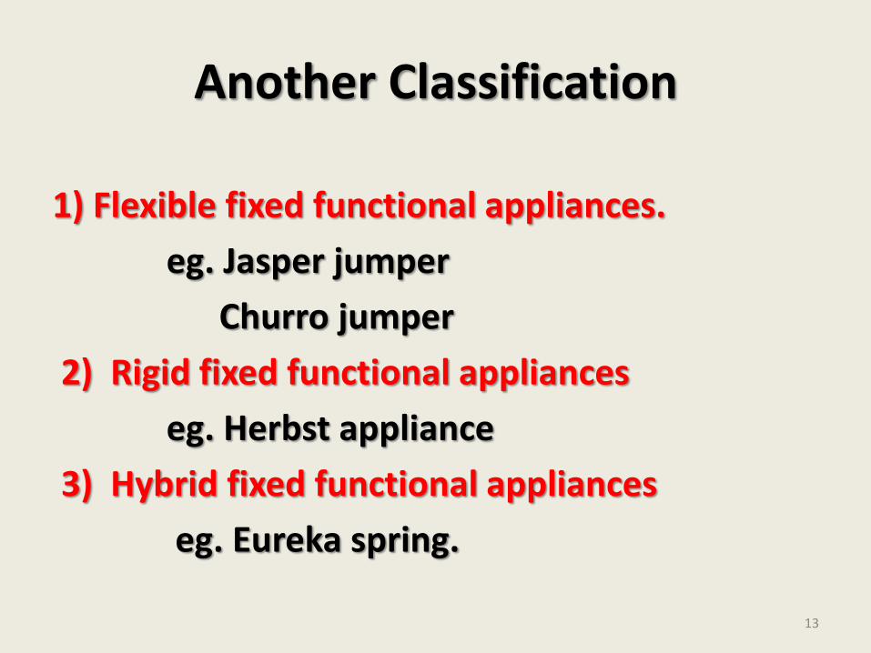
Another Classification
1) Flexible fixed functional appliances.
eg. Jasper jumper
Churro jumper
2) Rigid fixed functional appliances
eg. Herbst appliance
3) Hybrid fixed functional appliances
eg. Eureka spring.
13
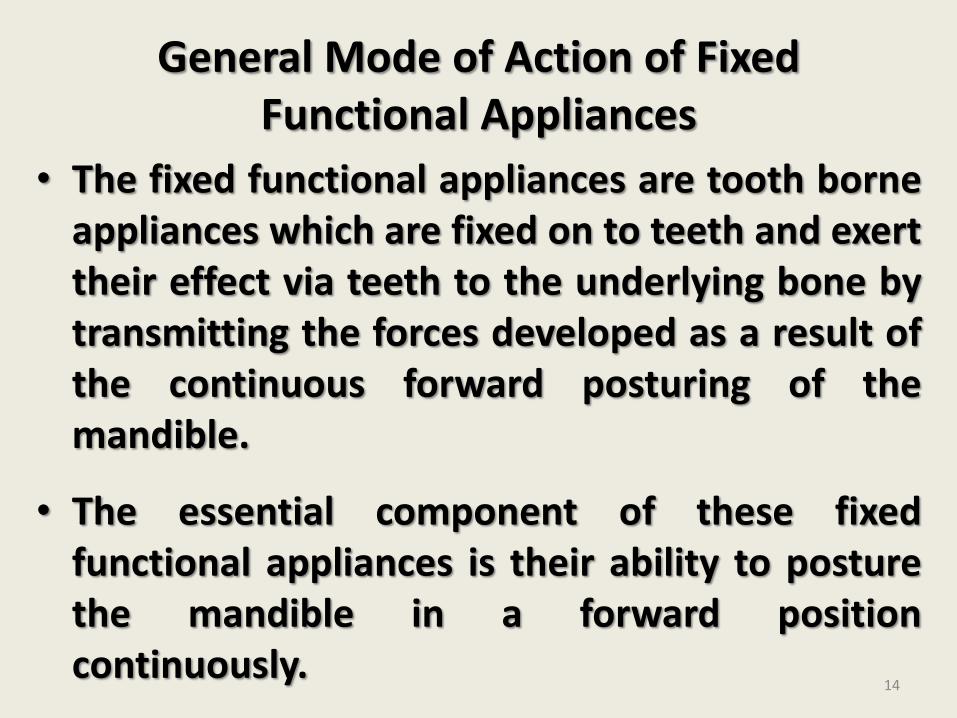
General Mode of Action of Fixed Functional Appliances
• The fixed functional appliances are tooth borneappliances which are fixed on to teeth and exerttheir effect via teeth to the underlying bone bytransmitting the forces developed as a result ofthe continuous forward posturing of themandible.
• The essential component of these fixedfunctional appliances is their ability to posturethe mandible in a forward positioncontinuously.
14
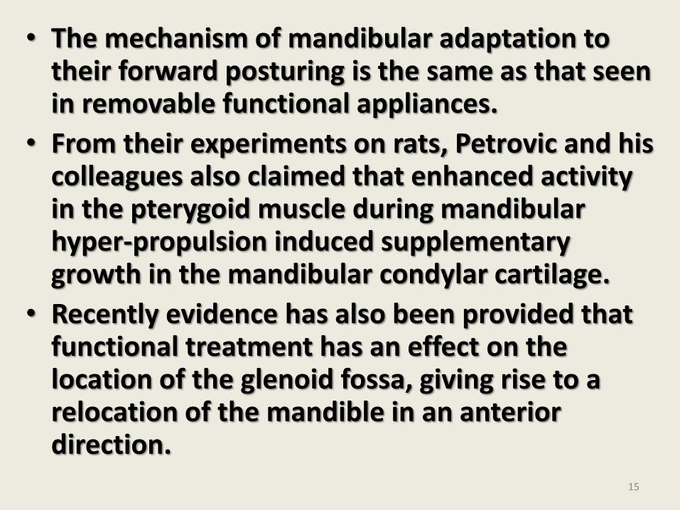
• The mechanism of mandibular adaptation to their forward posturing is the same as that seen in removable functional appliances.
• From their experiments on rats, Petrovic and his colleagues also claimed that enhanced activity in the pterygoid muscle during mandibular hyper-propulsion induced supplementary growth in the mandibular condylar cartilage.
• Recently evidence has also been provided that functional treatment has an effect on the location of the glenoid fossa, giving rise to a relocation of the mandible in an anterior direction.
15
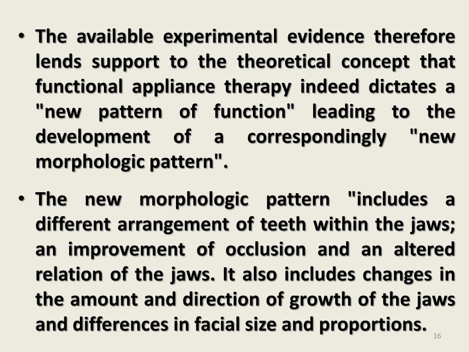
• The available experimental evidence thereforelends support to the theoretical concept thatfunctional appliance therapy indeed dictates a"new pattern of function" leading to thedevelopment of a correspondingly "newmorphologic pattern".
• The new morphologic pattern "includes adifferent arrangement of teeth within the jaws;an improvement of occlusion and an alteredrelation of the jaws. It also includes changes inthe amount and direction of growth of the jawsand differences in facial size and proportions.
16
Indications
• It is used primarily in actively growingindividuals with favorable facial growthpatterns.
• Class II skeletal pattern with mandibulardeficiency
• Lack of vertical development in lower faceheight
17
• Mouth breathers
• Uncooperative patients
• Patients who do not respond to removable functional appliance
• Concomitant upper molar distalization cases
18
Contraindications
• Non-growing individuals
• Cl . II skeletal pattern with maxillary excess
• Increased lower anterior face height
• Cl. I molar relationship
• Shallow over bite
• Cases prone to root resorption
• Malaligned dental arches
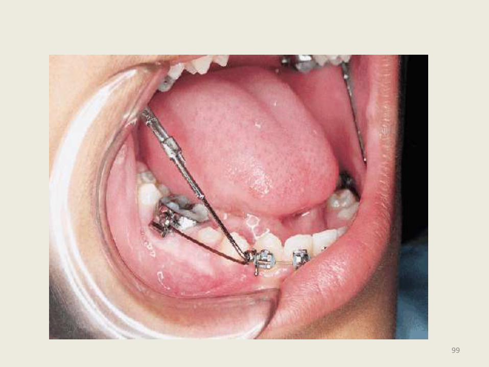
19
Contraindications
• Pseudo deep bite due to supra eruption of
the anterior teeth (“Gummy” smile)
• Proclined mandibular anterior teeth
20
Herbst Appliance
• Fixed functional appliances first appeared inthe early 1900s, when Emil Herbst in 1905presented his system at the BerlinInternational Dental Congress.
• This device was one of the early attempts toproduce mechanically a “jumping of thebite”; an idea that had earlier beenadvocated by Kingsley, among others.
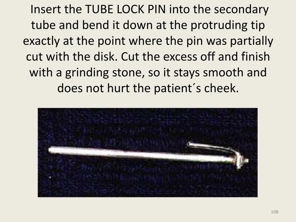
21
• Bite jumping is the production of a change in sagittal intermaxillary jaw relationship by anterior displacement of mandible.
• In 1977, Dr. Hans Pancherz resurrected the Herbst appliance for use as an experimental tool in clinical research.
• Pancherz (1979) called attention to the possibilities for stimulation of mandibular growth by means of the Herbst appliance.
22
• Since 1979 the Herbst appliance has gained increasing attention. The Herbst appliance method has been found most useful in the management of severe class II malocclusions associated with retrognathic mandible.
• The appliance can be compared to an artificial joint working between the maxilla and the mandible.
23
• A bilateral telescopic mechanism attached to orthodontic bands keeps the mandible in an anterior jumped position. Each telescope consists of a tube, a plunger, two pivots (axle), and two locking screws that prevent the telescoping parts from slipping past the pivots.
• Originally, the telescoping parts of the Herbstappliance were curved conforming to curve of spee. The later designs were, however, as straight as they are today.
24
25
26
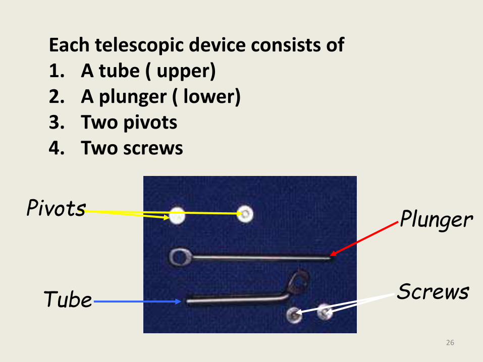
Plunger
Tube
Pivots
Screws
Each telescopic device consists of 1. A tube ( upper)2. A plunger ( lower)3. Two pivots 4. Two screws
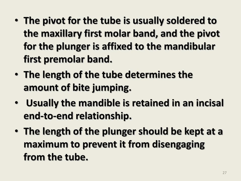
• The pivot for the tube is usually soldered to the maxillary first molar band, and the pivot for the plunger is affixed to the mandibular first premolar band.
• The length of the tube determines the amount of bite jumping.
• Usually the mandible is retained in an incisal end-to-end relationship.
• The length of the plunger should be kept at a maximum to prevent it from disengaging from the tube.
27
• A large interpivot distance prevents the plunger from slipping out of the tube when the mouth is opened wide.
• Therefore the upper pivot should be placed distally on the molar band, and the lower pivot should be placed mesially on the premolar band.
• If the plunger is too long, however, it may protrude too far behind the tube and injure the buccal mucosa distal to the maxillary permanent first molar.
28
• If the plunger disengages from the tube on mouth opening, it may get stuck in the tube opening on subsequent mouth closure and damage the appliance i.e, break or loosen the bands.
• The Construction Bite:
• The patient is motivated and is allowed to practice to posture the mandible forward with the midlines coinciding, in this new position the construction bite is recorded. Wax bite is the blue print for the appliance.
29
• Although conventional orthodontic bands(0.15mm thick) can be used, Pancherzprefers his current approach of casting splints of chromium-cobalt alloy that incorporates molars and are cemented as units with glass ionomer cement.
• This saves chairside time and causes a few clinical problems.
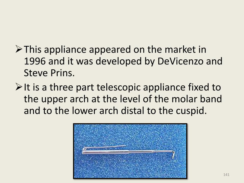
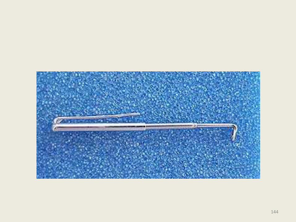
30
REACTIVATION
• Reactivation is accomplished by : replacing the original tubes with longer tubes and sliding short section of unused upper sleeve over each lower plunger.
31
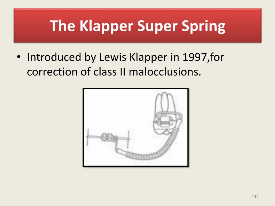
Effects Of Herbst Appliance• The Herbst appliance is the effective
modality in the treatment of class II malocclusion. Normalization of occlusion is generally accomplished within 6-8 to months.
• Over corrected sagittal dental arch relationship and incomplete cuspalinterdigitation at the end of treatment are to be expected before settling occurs.
• Improvement in sagittal and vertical occlusion relationships during treatment is a result of both skeletal and dental changes (Pancherz, 1982).
32
Sagittal Changes
• Restrains maxillary growth and decreases SNA angle.
• Increases mandibular length which can be attributed to condylar growth stimulation as an adaptive reaction to the forward positioning of mandible.
• Sagittal condylar growth increases whereas vertical condylar growth is relatively unaffected.
33
• The telescope mechanism produces a posterior directed force on the upper teeth and an anterior directed force on the lower teeth, resulting in distal tooth movements in the maxillary buccal segements and mesial tooth movements in the mandible.
• VERTICAL CHANGES:
a) Skeletal:
• Increase in lower anterior facial height (LAFH) due to eruption of lower posterior teeth.
• Increase in gonial angle.34
b) Dental
• Overbite reduction is primarily accomplished by intrusion of lower incisors and enhanced eruption of lower molars.
• Part of the registered changes in the vertical position of the mandibular incisors results from proclination of these teeth.
• Because of vertical dental changes, maxillary and mandibular occlusal planes tip down.
35
LATE POST TREATMENT EFFECTS:
• When examining patients treated with the Herbst appliance 5 to 10 yrs after treatment, several effects can be observed.
• Class I dental arch relationship is maintained by stable cuspal interdigitation of upper and lower teeth.
• Teeth locked in a stable position to the mandible are more likely to transfer maxillary growth forces to the mandible (or vice versa) and thus possibly act as restricting or stimulating, factors on mandibular growth.
36

• Thus a functionally stable occlusion after Herbst or any orthodontic therapy could be more important for lasting treatment results than the post treatment growth pattern.
Ideal Treatment Period For Long Term Stability:
• In order to favour occlusal stability after treatment and to reduce the time of post treatment retention, Herbst therapy in the permanent dentition at or just after peak height velocity is recommended.
37
• Benefit Of Class Ii Patients From Herbst Treatment In Terms Of Improved Temporo Mandibular Joint
Function:
• Disc Position:• A slight retrusion of the disc compared with
pretreatment values is seen at the end of treatment (Pancherz et al 1999) can be due to remodellingprocess of condyle and fossa, remodelling of the disc (Nagy and Daniel, 1992).
• Until further knowledge is available, the Herbstappliance must be considered the only functional appliance able to improve the position of the articulardisc during treatment. With partial disc displacement, there is a good prognosis for disc repositioning.
38
Retention After Herbst Treatment
• A stable functional occlusion after treatment counteracts the relapse tendency.
• A period of active retention is sometimes necessary until the occlusion has settled or a fixed mechanotherapy should be started.
• The activator is a suitable active retention device after herbst treatment.
39
• The herbst appliance is a very effective treatment modality for correction of class II malocclusion.
• But it should not be looked on as a substitute for removable functional appliances such as the activator or bionator etc..
• In the mixed dentition a removable functional appliance should be used to make the Class II treatment most effective.
40
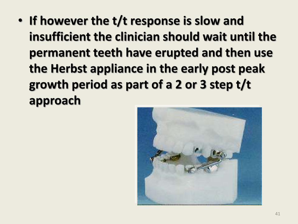
• If however the t/t response is slow and insufficient the clinician should wait until the permanent teeth have erupted and then use the Herbst appliance in the early post peak growth period as part of a 2 or 3 step t/t approach
41
42
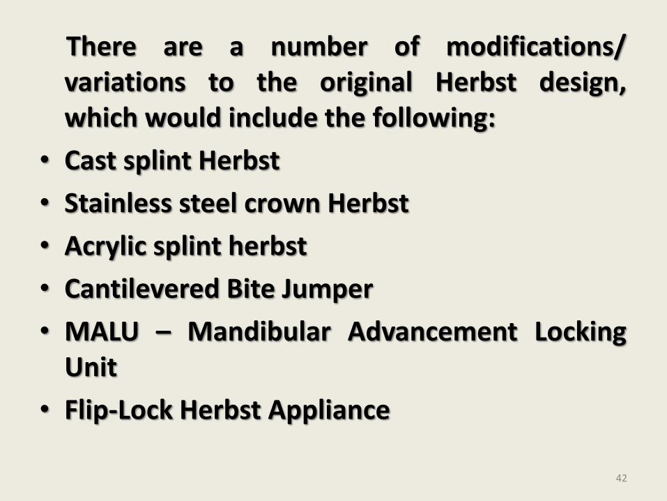
There are a number of modifications/variations to the original Herbst design,which would include the following:
• Cast splint Herbst
• Stainless steel crown Herbst
• Acrylic splint herbst
• Cantilevered Bite Jumper
• MALU – Mandibular Advancement LockingUnit
• Flip-Lock Herbst Appliance
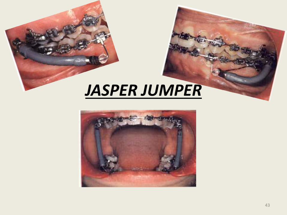
JASPER JUMPER
43
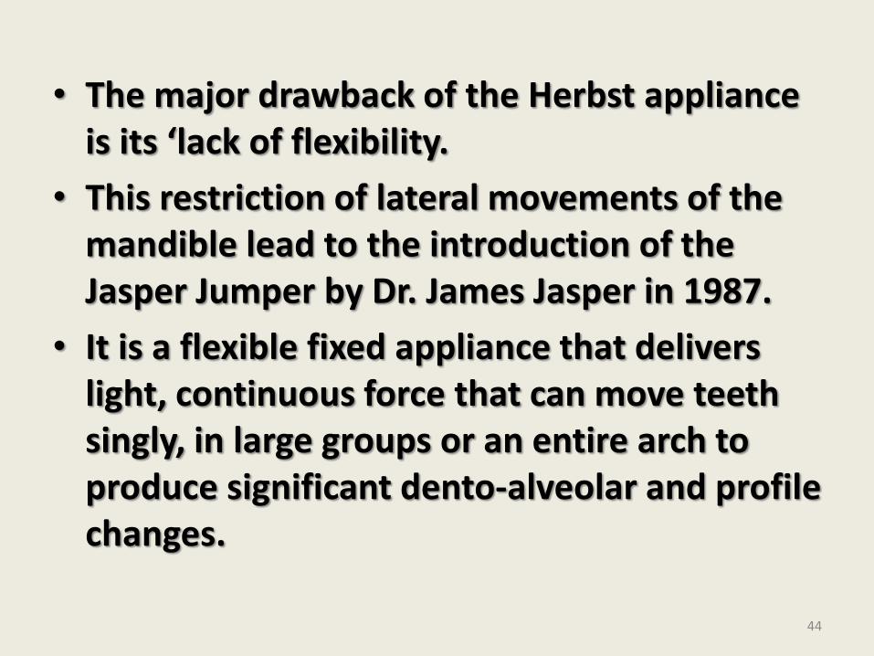
• The major drawback of the Herbst appliance is its ‘lack of flexibility.
• This restriction of lateral movements of the mandible lead to the introduction of the Jasper Jumper by Dr. James Jasper in 1987.
• It is a flexible fixed appliance that delivers light, continuous force that can move teeth singly, in large groups or an entire arch to produce significant dento-alveolar and profile changes.
44
45
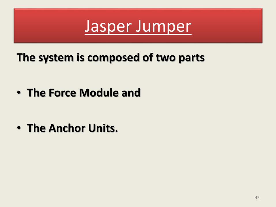
Jasper Jumper
The system is composed of two parts
• The Force Module and
• The Anchor Units.
46
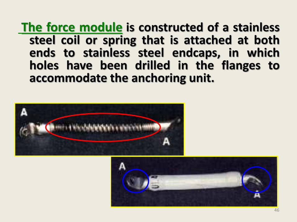
The force module is constructed of a stainlesssteel coil or spring that is attached at bothends to stainless steel endcaps, in whichholes have been drilled in the flanges toaccommodate the anchoring unit.
47
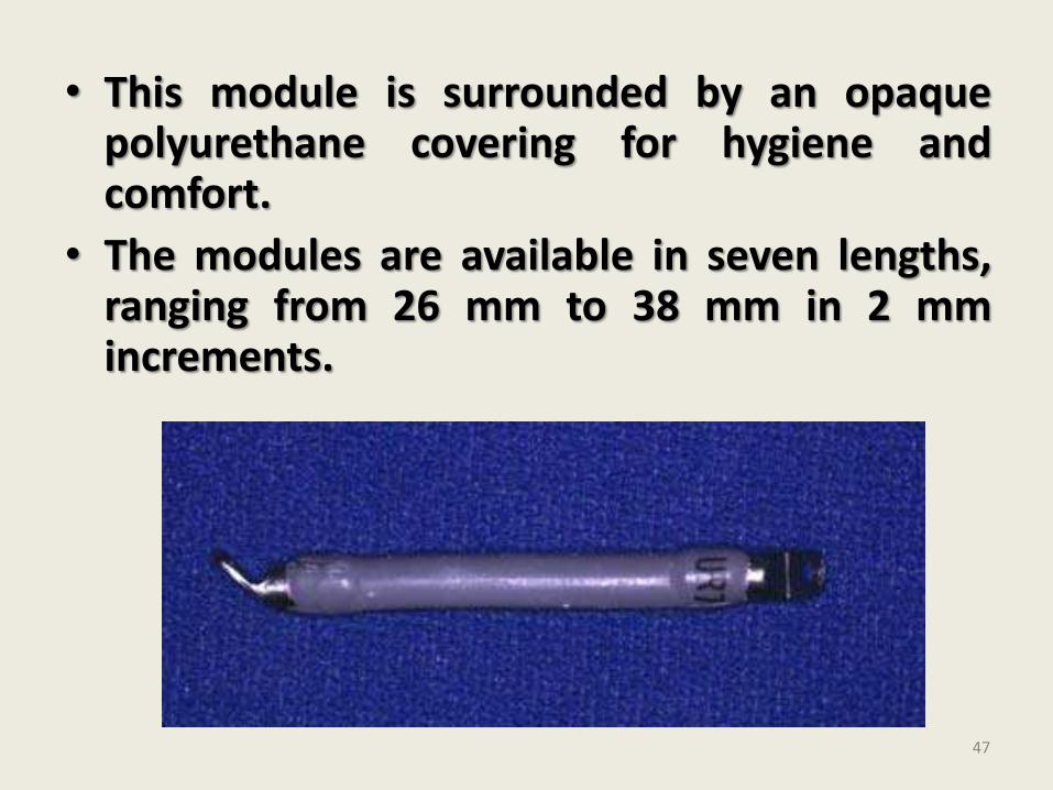
• This module is surrounded by an opaquepolyurethane covering for hygiene andcomfort.
• The modules are available in seven lengths,ranging from 26 mm to 38 mm in 2 mmincrements.
• When the force module is straight, it remains passive. As the teeth come into occlusion the spring of the force module is curved axially as the muscles of mastication elevate the mandible producing a range of forces from 1 to 16 ounces.
• This kinetic energy is then captured when the force module is curved, and the force is converted to potential energy to be used for a variety of clinical effects.
48
• If properly installed to produce mandibular advancement, the spring mechanism is curved or activated 4 mm relative to its resting length, thus storing about 8 ounces (250g) of potential for force delivery.
• If less force is desired (e.g force levels that produce tooth movement alone), the jumper is not activated fully.
• Increasing the activation beyond 4 mm does not yield more force from the module but only builds excessive internal stress in the module. The tendency to add more force for faster treatment result is to be avoided.
49
• Anchor units:
• A number of methods are available to anchor the force modules to either the permanent or mixed dentitions.
• 1) Attachment to the main arch wire:
• The most common method and the method originally designed by Dr. Jasper.
• When the jumper mechanism is used to correct a Class II malocclusion, the force module is attached posteriorly to the maxillary arch by a ball pin placed through the distal attachment of the force module, the module then extends anteriorly through the face bow tube on the upper first molar band. .
50
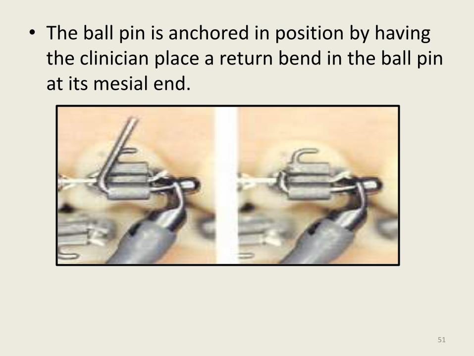
• The ball pin is anchored in position by having the clinician place a return bend in the ball pin at its mesial end.
51
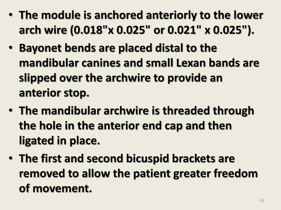
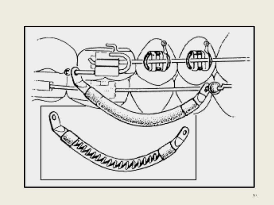
• The module is anchored anteriorly to the lower arch wire (0.018"x 0.025" or 0.021" x 0.025").
• Bayonet bends are placed distal to the mandibular canines and small Lexan bands are slipped over the archwire to provide an anterior stop.
• The mandibular archwire is threaded through the hole in the anterior end cap and then ligated in place.
• The first and second bicuspid brackets are removed to allow the patient greater freedom of movement.
52
53
• Disadvantages:
i. Unattached bicuspids tend to erupt above the occlusal plane as the . anterior teeth are intruded.
ii. When only the lower 1st bicuspid bracket used to be removed as originally suggested by Dr. Jasper, jaw opening used to be limited as the lower portion of the jumper tends to bind at the 2nd bicuspid.
iii. Replacement of a broken jumper required removal of the entire archwire.
54
iv. If an archwire breaks or becomes untied at the disal tieback, all the force is transferred to the anterior teeth, which tends to tip them forward depress them and open space.
v. Removing the Jumper for an occlusal check is time consuming.
vi. In an extraction case, it is difficult to close spaces because the jumper must be attached to the arch before closing loops are bent)
55
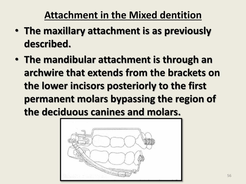
Attachment in the Mixed dentition
• The maxillary attachment is as previously described.
• The mandibular attachment is through an archwire that extends from the brackets on the lower incisors posteriorly to the first permanent molars bypassing the region of the deciduous canines and molars.
56
• In a mixed dentition patient the use of a transpalatal arch and fixed lower lingual arch is mandatory to control potential unfavorable side effects.
57
58
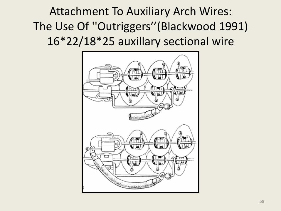
Attachment To Auxiliary Arch Wires:The Use Of ''Outriggers’’(Blackwood 1991)
16*22/18*25 auxillary sectional wire
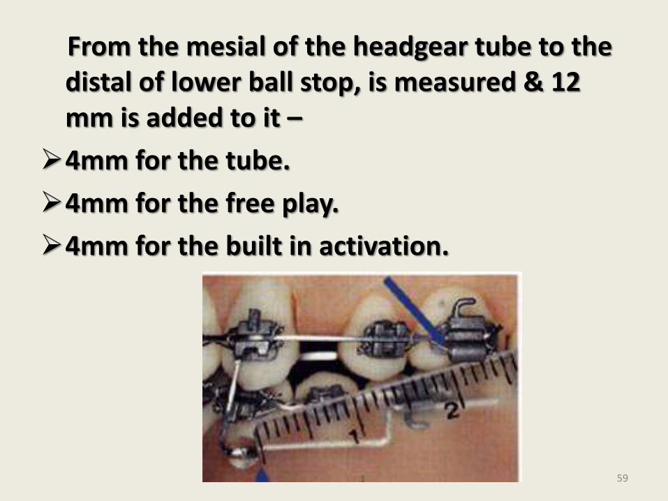
From the mesial of the headgear tube to the distal of lower ball stop, is measured & 12 mm is added to it –
4mm for the tube.
4mm for the free play.
4mm for the built in activation.
59
Types of forces produced:
• Bilateral directions of force generated by the modules include sagittal, intrusive and expansion forces.
• Sagittal forces
• - distalize the posterior anchor unit (maxillary 1st and 2nd molars). - Apply anterior force to mandible and mandibular dentition
• Intrusive forces-in the maxillary posterior and mandibular anterior regions.
60
• Buccal force
• - due to intrusive force acting along the buccal surfaces of the maxillary teeth -produces maxillary arch expansion.
• Modules curving outwards - Vestibular shielding effect
• Expansion forces can minimized or eliminated through the use of a transpalatalarch or a heavy arch wire that has been narrowed and to which buccal root torque has been applied.
61
TREATMENT EFFECTS:
• Maxillary adaptations:
• i) Head gear effect
• One treatment effect produced most easily is distalization of the upper posterior segment or the headgear effect.
• For this the maxillary arch wire must not be cinched or tied back, but remain straight extended past the buccal tubes.
• Involves light forces (2-4 ounces)
62
• Minimal changes in the mandibular dentition.
• This effect can be produced in actively growing as well as adult patients.
ii) Retraction of anterior teeth
• Upper canines alone or all the six anterior teeth can be retracted in both extraction and non-extraction patients with a NiTi coil or an intramaxillary elastic, with the posterior maxillary dentition supported by the force module. iii) Dental asymmetries
• The force module system also can be used in-patients who have sagittal dental asymmetries.
63
• In a patient with a Class II subdivision type of malocclusion the maxillary archwire can be tied back on the side of the existing Class I molar relationship.
64
• Additional applications:
• Can be used to support anchorage for the retraction of maxillary anterior teeth in patient with class I occlusions.
• In Class III malocclusion - reverse placement.
• Correction of anterior crossbites in patients with pseudo class III malocclusions.
• Post surgical stabilization of class II or “class III malocclusions.
65
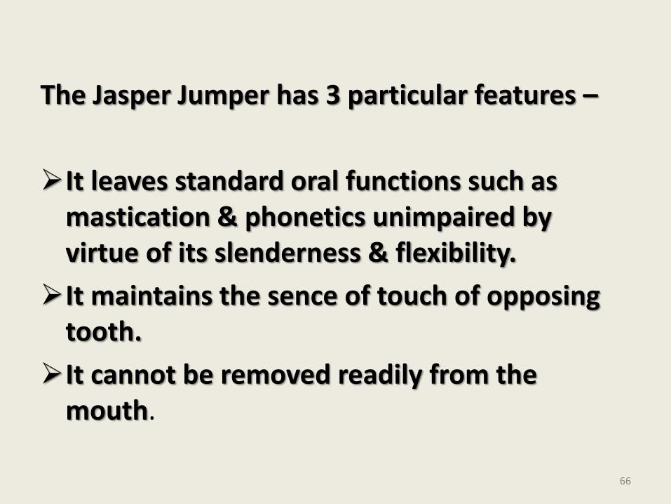
The Jasper Jumper has 3 particular features –
It leaves standard oral functions such as mastication & phonetics unimpaired by virtue of its slenderness & flexibility.
It maintains the sence of touch of opposing tooth.
It cannot be removed readily from the mouth.
66
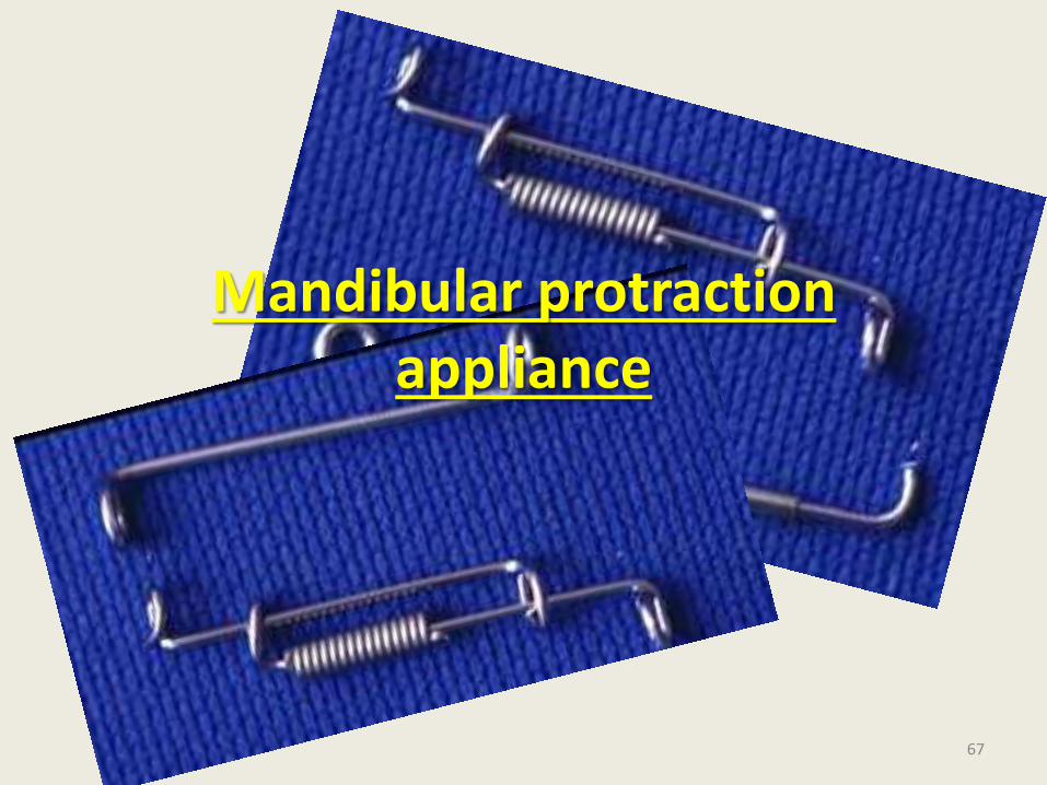
Mandibular protraction appliance
67
• Correctly relating the maxilla and the mandible has always been a primary concern of orthodontists in treating class II malocclusions .Device proposed for such treatment have ranged from intermaxillary elastics to head gear to removable functional appliances.
• More recent appliances as Herbst & Jasper jumper, have advantage of being rigidly fixed & less dependent on patient co operation
68
Advantages –
Ease of fabrication.
Low cost.
Infrequent breakage.
Patient comfort.
Rapid installation.
69
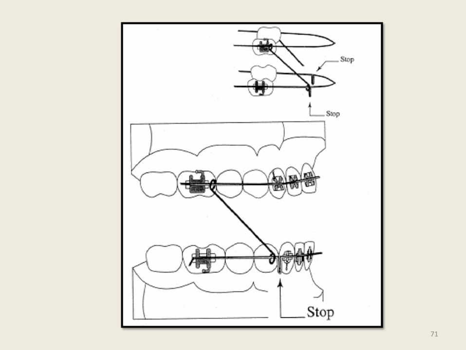
• The first type of mandibular protraction appliance (MPA) requires stainless steel edgewise archwires in both arches.
• The mandibular archwire requires stops such as circles, crimpable hooks, or loops distal to the cuspids to prevent direct contact between the appliance and the bonded brackets.
70
71
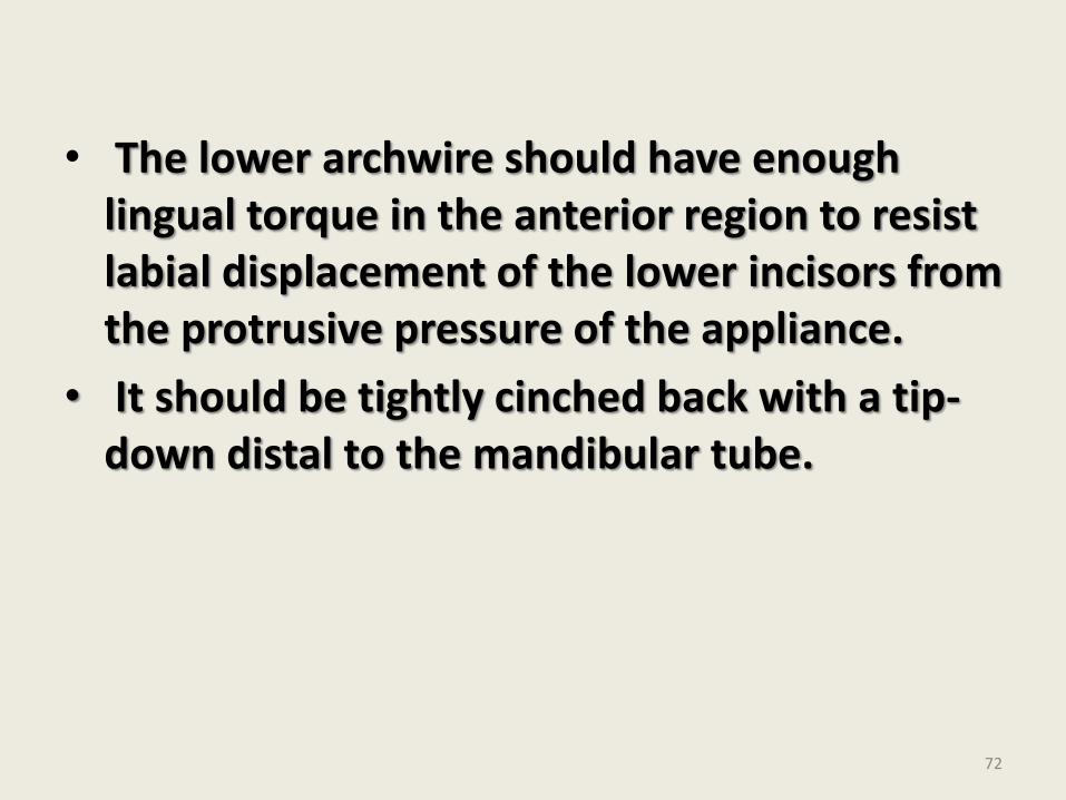
• The lower archwire should have enough lingual torque in the anterior region to resist labial displacement of the lower incisors from the protrusive pressure of the appliance.
• It should be tightly cinched back with a tip-down distal to the mandibular tube.
72
•
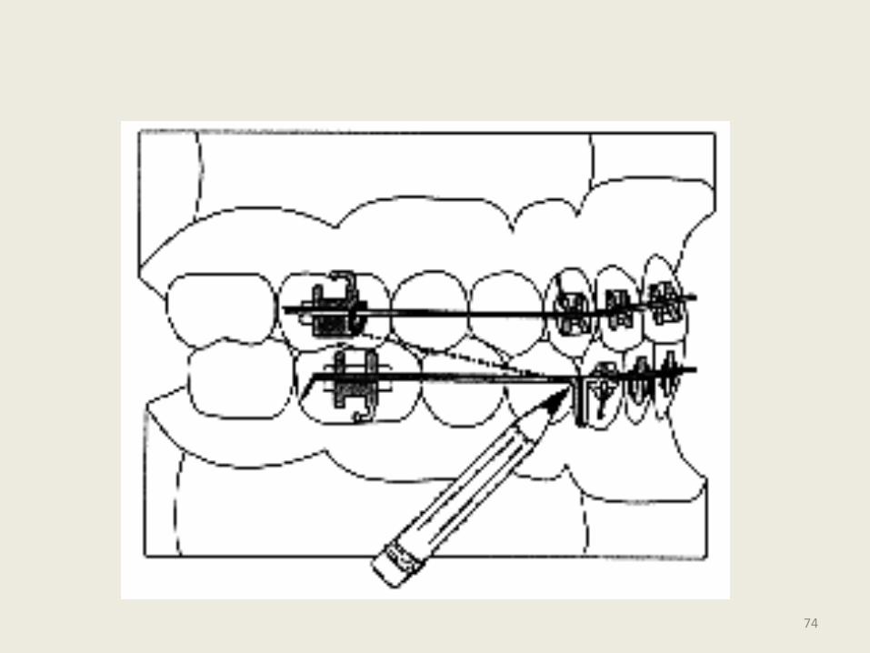
• Each side of the appliance is made by bending a small loop at a right angle to the end of an .032" stainless steel wire .
• The length of the appliance is then determined by protruding the mandible into a position with proper overjet, overbite, and midline correction and measuring the distance from the mesial of the maxillary tube to the stop on the mandibular archwire.
73
74
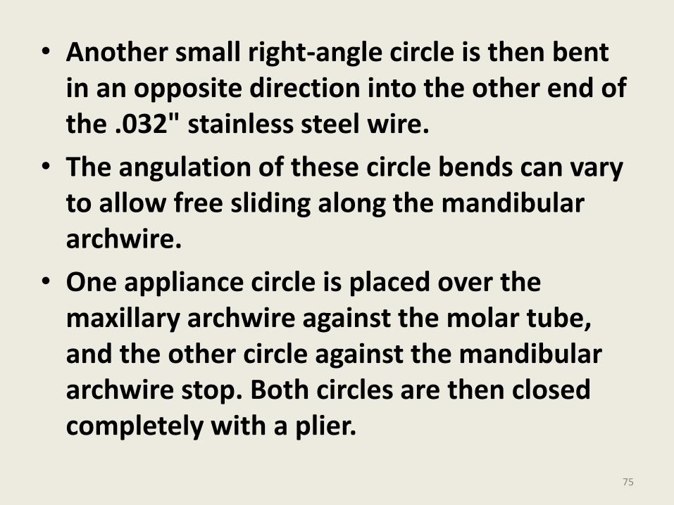
• Another small right-angle circle is then bent in an opposite direction into the other end of the .032" stainless steel wire.
• The angulation of these circle bends can vary to allow free sliding along the mandibular archwire.
• One appliance circle is placed over the maxillary archwire against the molar tube, and the other circle against the mandibular archwire stop. Both circles are then closed completely with a plier.
75
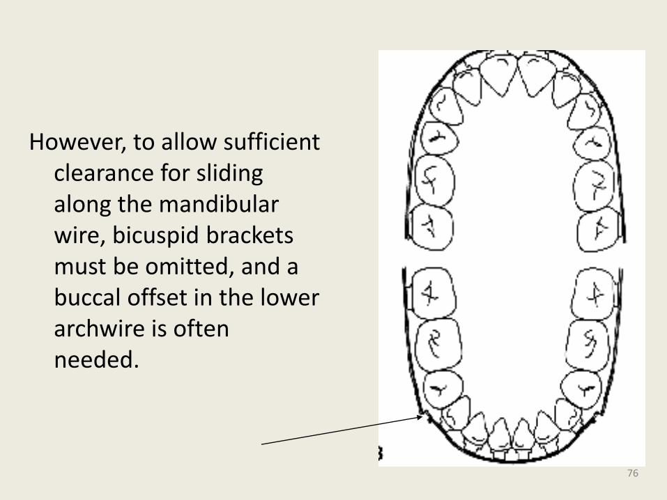
However, to allow sufficient clearance for sliding along the mandibular wire, bicuspid brackets must be omitted, and a buccal offset in the lower archwire is often needed.
76
• The radical improvement accounts not only for the mandibular growth , but dentoalveolar changes imposed by appliances constant pressure.
• With careful patient selection & judicious use , this appliance works quite effectively.
77
• But impossibility of bonding the lower bicuspids combined with appliances limited mouth opening & frequent dislodgement of molar bands made the author to develop second protrusion appliance.
78
MPA.2
79
• The MPA No. 2 is fabricated by making right-angle circles in two pieces of .032’’ stainless steel wire. A small piece of rigid coil or stainless steel tubing is slipped over one of the wires.
• Coil can be made from.024’’s.s wire.
80
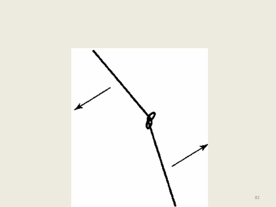
One end of each wire is inserted through the other wire's loop , so that each wire passes through the other up to the limit of the wire coil . The coil prevents the two wires from interfering with each other and ensures their correct relationship.
81
82
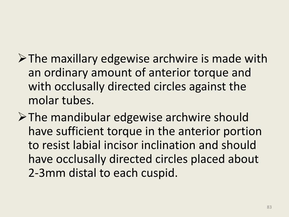
The maxillary edgewise archwire is made with an ordinary amount of anterior torque and with occlusally directed circles against the molar tubes.
The mandibular edgewise archwire should have sufficient torque in the anterior portion to resist labial incisor inclination and should have occlusally directed circles placed about 2-3mm distal to each cuspid.
83
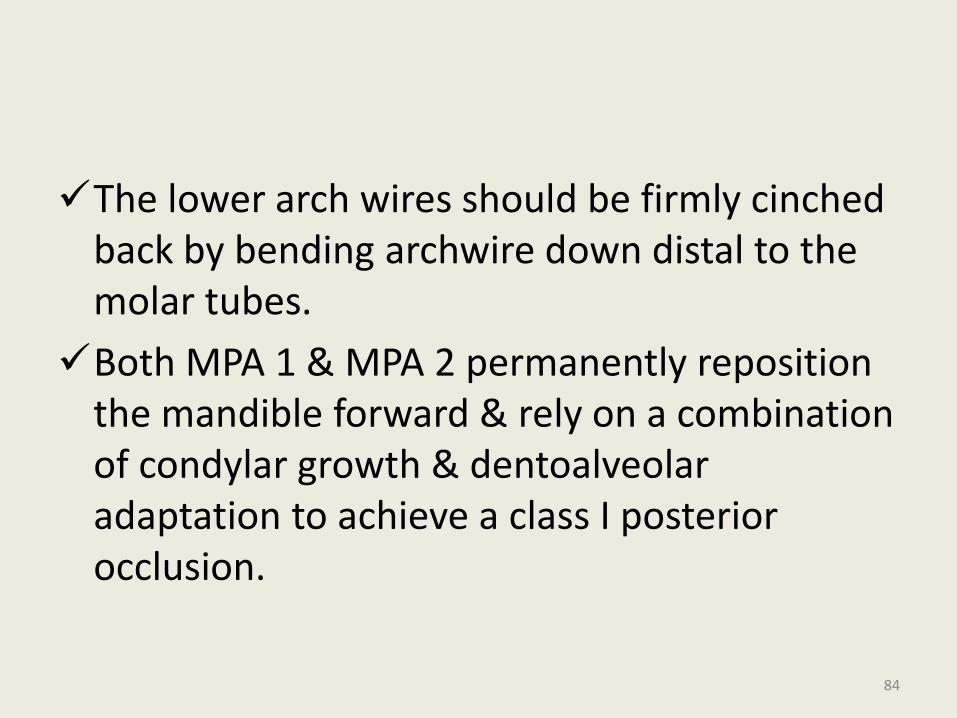
The lower arch wires should be firmly cinched back by bending archwire down distal to the molar tubes.
Both MPA 1 & MPA 2 permanently reposition the mandible forward & rely on a combination of condylar growth & dentoalveolar adaptation to achieve a class I posterior occlusion.
84
Advantages –
Ease of fabrication.
Low cost.
No special bands ,crowns or wire attachments.
No impressions or wax bite no lab. assistance.
Infrequent breakage.
They permit greater range of motion & are less restrictive of movements compared to other appliances.
Patient comfort.
Rapid installation.
85

MPA 3
86
The Mandibular Protraction Appliances have proven reliable and efficient in the correction of various aspects of Class II malocclusions, including overjet, overbite, midline shift, spacing, and molar position.
Unfortunately, problems of breakage, restricted opening, and patient discomfort associated with the MPA No. 1 and the difficulty of chair side construction of the MPA No. 2 have discouraged many orthodontists from using these appliances.
87
Appliance Construction
The parts needed for the construction of the MPA No. 3 are:
• Two maxillary tubes of .045" internal diameter, each about 27mm long.
• Two maxillary loops of .040" stainless steel wire, each about 13mm long, with a loop bent into one end at an angle of about 130° to the horizontal.
• Two mandibular rods of .036" stainless steel wire, each about 27mm long. 88
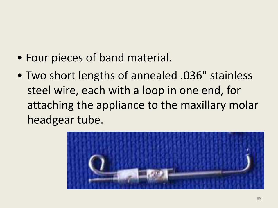
• Four pieces of band material.
• Two short lengths of annealed .036" stainless steel wire, each with a loop in one end, for attaching the appliance to the maxillary molar headgear tube.
89
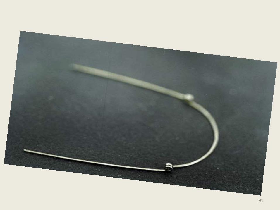
Prepare a stainless steel edgewise mandibular archwire by bending an “O” loop on each side distal to the cuspid, winding the wire twice around a Tweed loop-forming plier.
preferably a .019’’x .025’’ wire, but smaller and more flexible wires such as .016’’x .022’’ and .017’’x .025’’ have also reportedly resisted breakage with the MPA No. 3
90
91
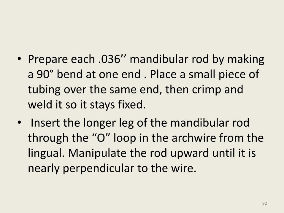
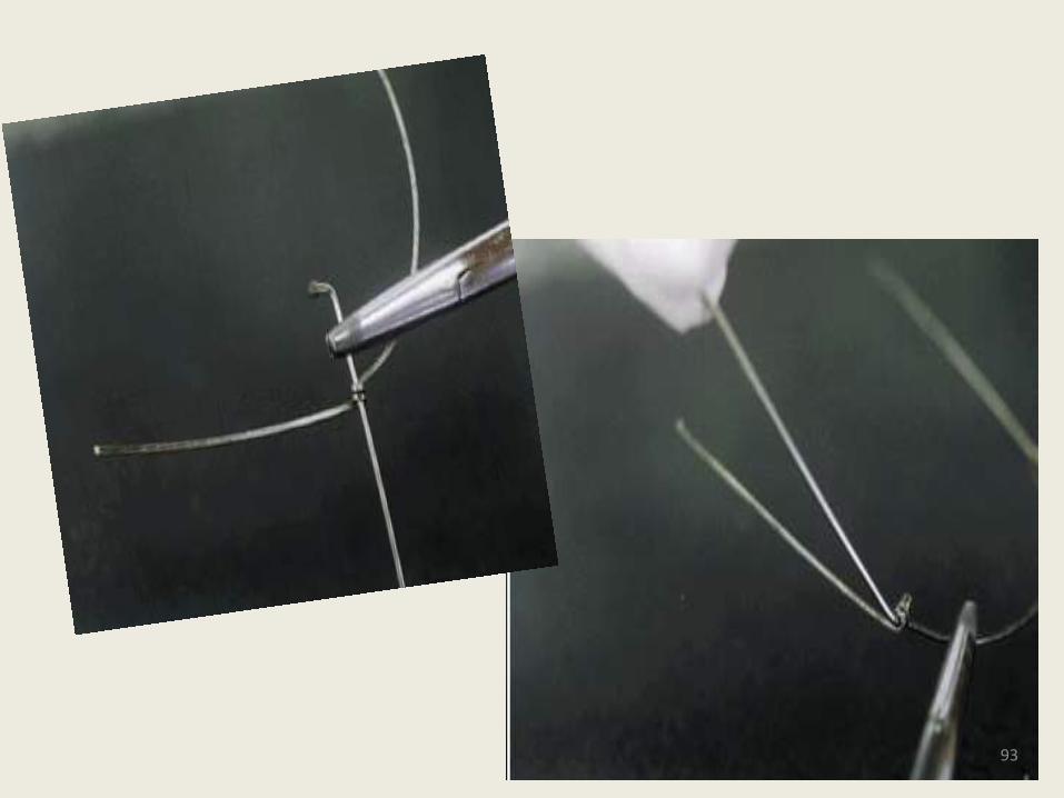
• Prepare each .036’’ mandibular rod by making a 90° bend at one end . Place a small piece of tubing over the same end, then crimp and weld it so it stays fixed.
• Insert the longer leg of the mandibular rod through the “O” loop in the archwire from the lingual. Manipulate the rod upward until it is nearly perpendicular to the wire.
92
93
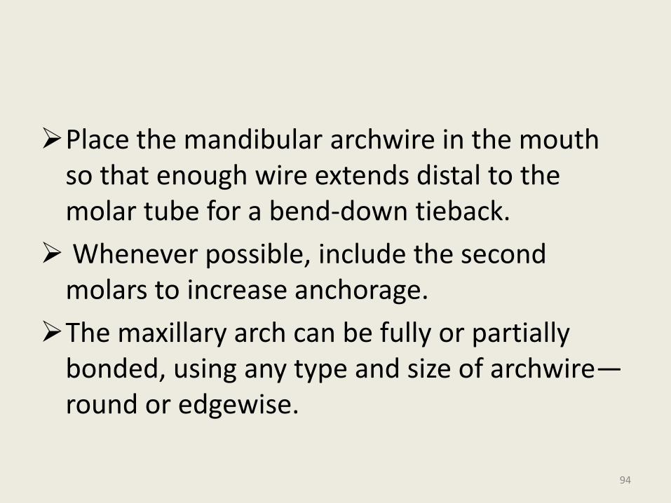
Place the mandibular archwire in the mouth so that enough wire extends distal to the molar tube for a bend-down tieback.
Whenever possible, include the second molars to increase anchorage.
The maxillary arch can be fully or partially bonded, using any type and size of archwire—round or edgewise.
94
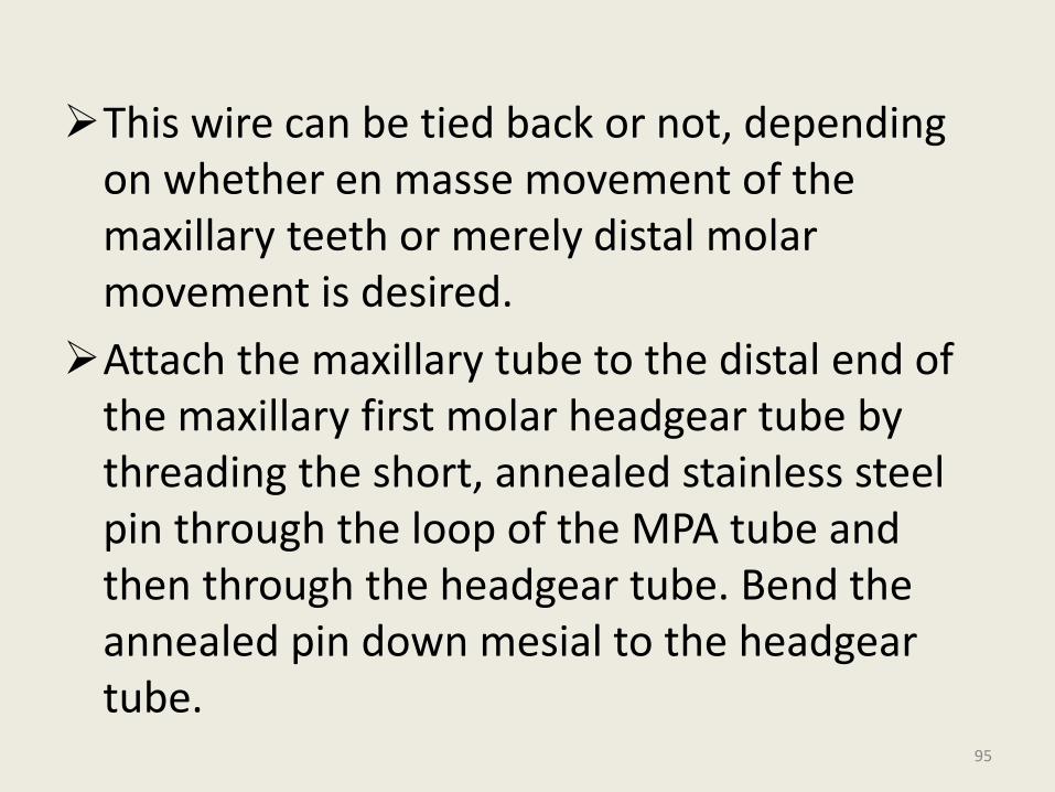
This wire can be tied back or not, depending on whether en masse movement of the maxillary teeth or merely distal molar movement is desired.
Attach the maxillary tube to the distal end of the maxillary first molar headgear tube by threading the short, annealed stainless steel pin through the loop of the MPA tube and then through the headgear tube. Bend the annealed pin down mesial to the headgear tube.
95
96
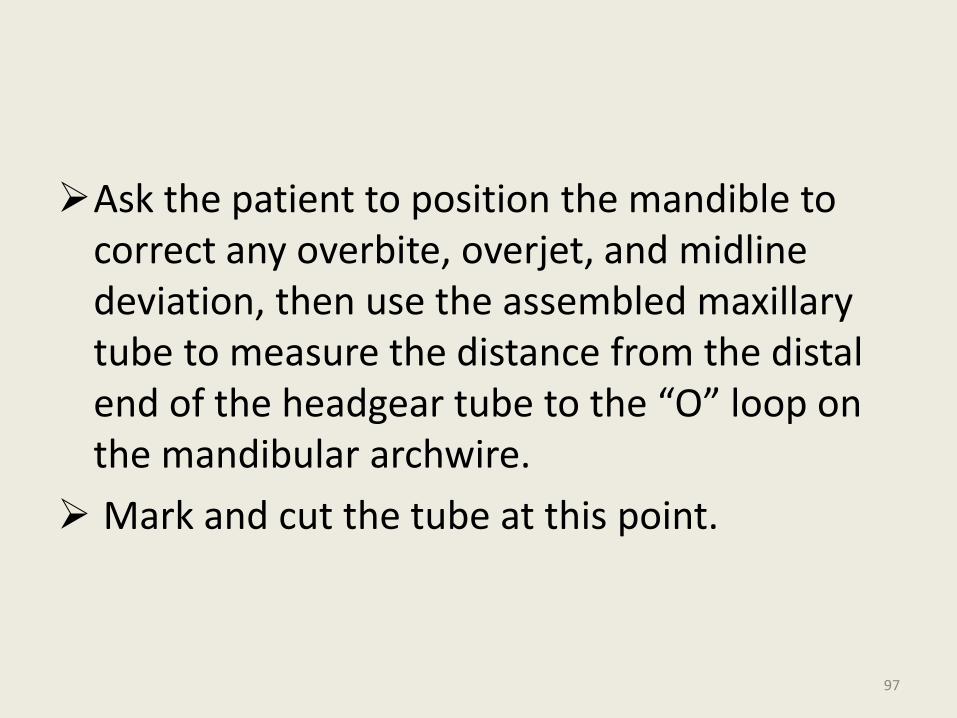
Ask the patient to position the mandible to correct any overbite, overjet, and midline deviation, then use the assembled maxillary tube to measure the distance from the distal end of the headgear tube to the “O” loop on the mandibular archwire.
Mark and cut the tube at this point.
97
• The MPA No. 3 allows almost unrestricted opening, to at least 50-55mm.
• As with the other MPAs, it can be used unilaterally; patients generally find this version more comfortable than the bilateral variety.
98
99
Advantages
It is more comfortable for the patient, and thus promotes better compliance.
• It offers greater range of motion.
• It is equally simple and inexpensive, but easier to place.
• It is adaptable to either Class II or Class III cases.
100
• It can be used for mandibular positioning or dentoalveolar movement.
• It causes less breakage of archwires and appliances and thus fewer emergency appointments.
101

MPA 4
102
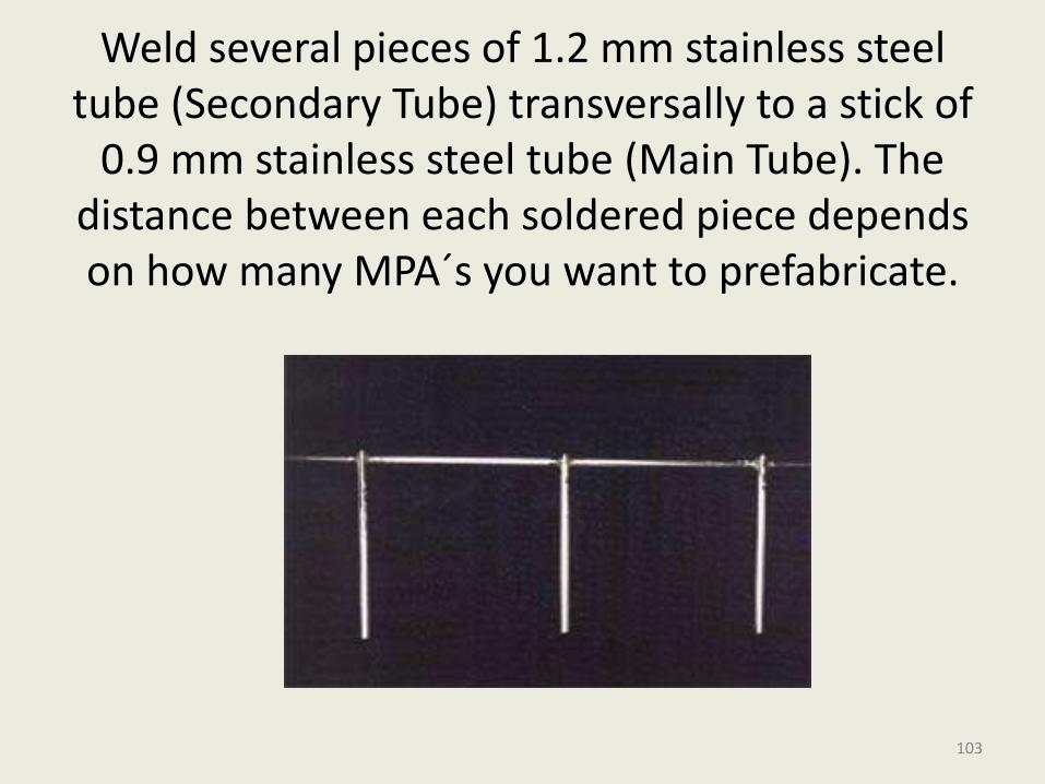
Weld several pieces of 1.2 mm stainless steel tube (Secondary Tube) transversally to a stick of
0.9 mm stainless steel tube (Main Tube). The distance between each soldered piece depends on how many MPA´s you want to prefabricate.
103
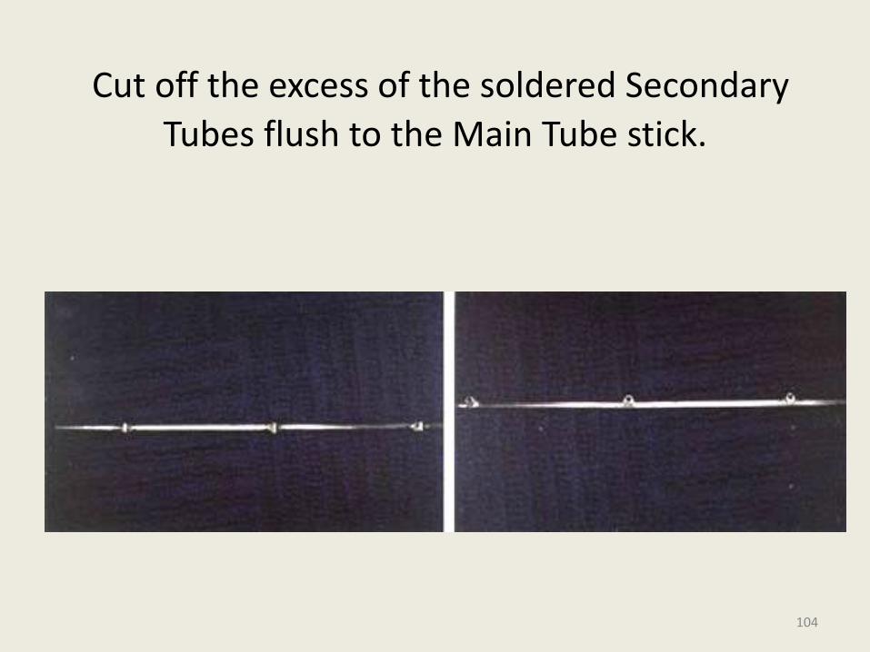
Cut off the excess of the soldered Secondary
Tubes flush to the Main Tube stick.
104
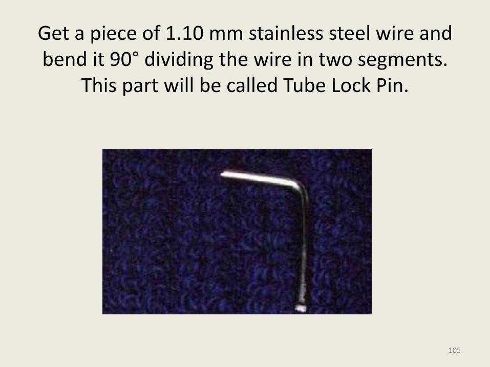
Get a piece of 1.10 mm stainless steel wire and bend it 90° dividing the wire in two segments.
This part will be called Tube Lock Pin.
105
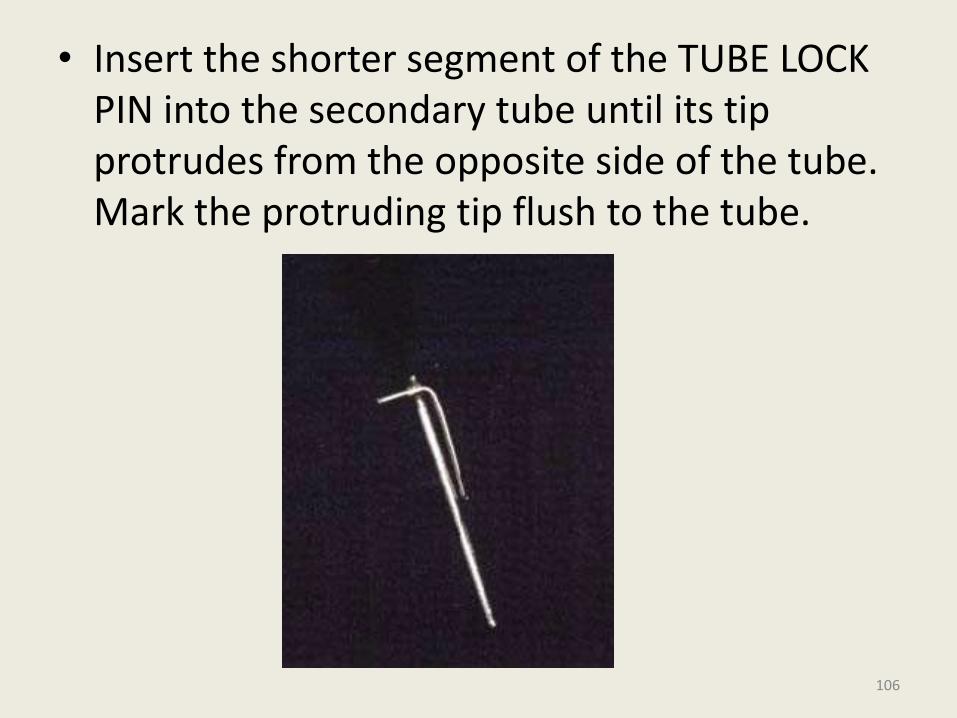
• Insert the shorter segment of the TUBE LOCK PIN into the secondary tube until its tip protrudes from the opposite side of the tube. Mark the protruding tip flush to the tube.
106
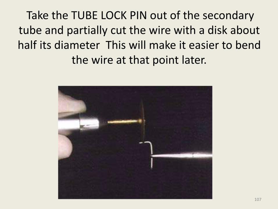
Take the TUBE LOCK PIN out of the secondary tube and partially cut the wire with a disk about half its diameter This will make it easier to bend
the wire at that point later.
107
Insert the TUBE LOCK PIN into the secondary tube and bend it down at the protruding tip
exactly at the point where the pin was partially cut with the disk. Cut the excess off and finish with a grinding stone, so it stays smooth and
does not hurt the patient´s cheek.
108
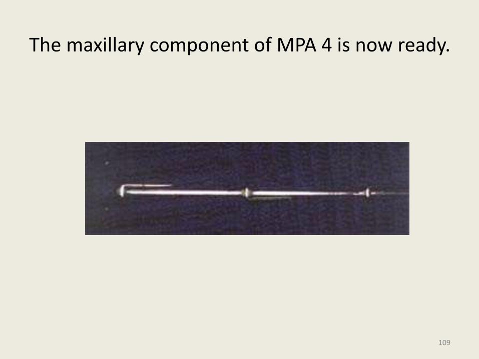
The maxillary component of MPA 4 is now ready.
109
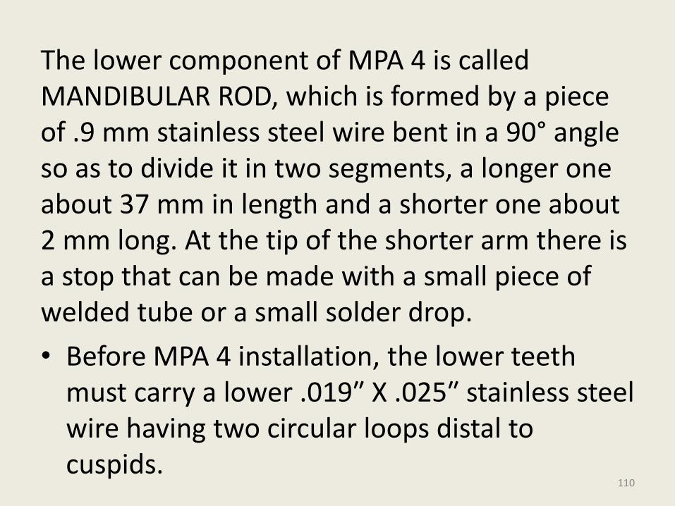
The lower component of MPA 4 is called MANDIBULAR ROD, which is formed by a piece of .9 mm stainless steel wire bent in a 90° angle so as to divide it in two segments, a longer one about 37 mm in length and a shorter one about 2 mm long. At the tip of the shorter arm there is a stop that can be made with a small piece of welded tube or a small solder drop.
• Before MPA 4 installation, the lower teeth must carry a lower .019″ X .025″ stainless steel wire having two circular loops distal to cuspids.
110
111
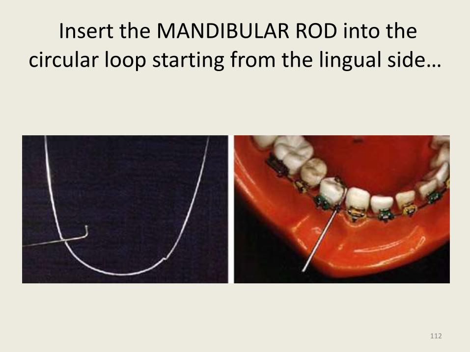
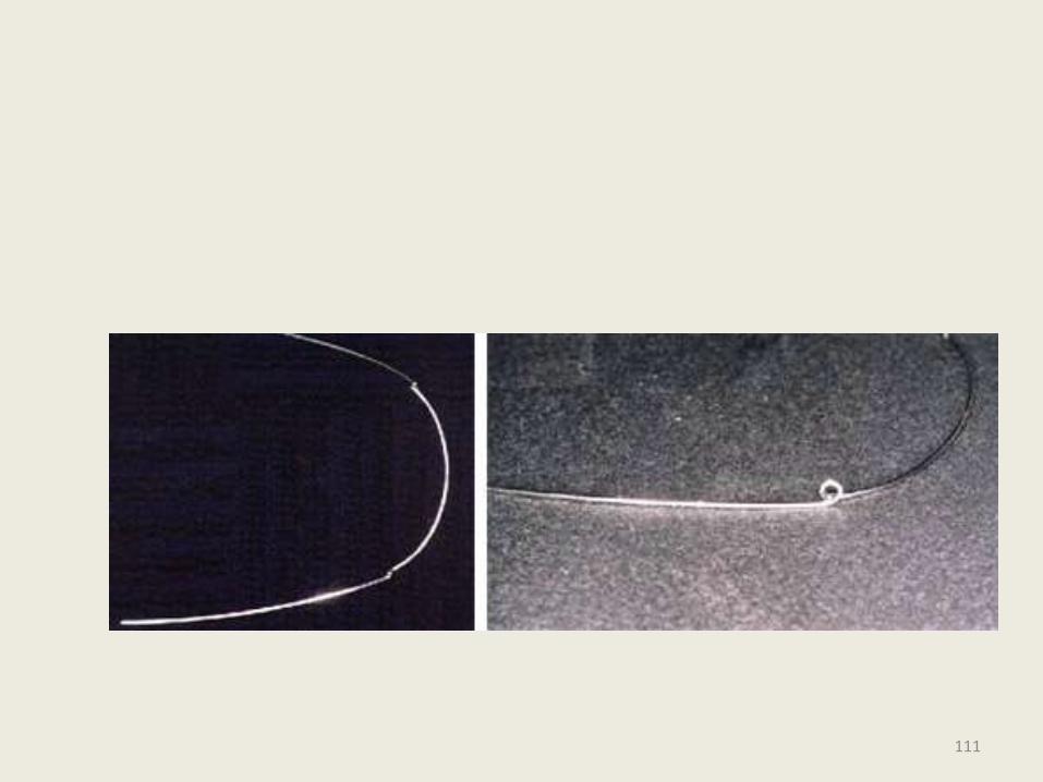
Insert the MANDIBULAR ROD into the circular loop starting from the lingual side…
112
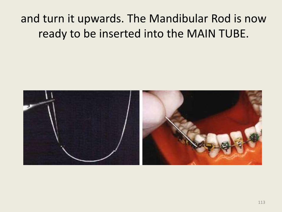
and turn it upwards. The Mandibular Rod is now ready to be inserted into the MAIN TUBE.
113
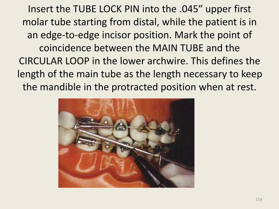
Insert the TUBE LOCK PIN into the .045″ upper first molar tube starting from distal, while the patient is in an edge-to-edge incisor position. Mark the point of
coincidence between the MAIN TUBE and the CIRCULAR LOOP in the lower archwire. This defines the length of the main tube as the length necessary to keep
the mandible in the protracted position when at rest.
114
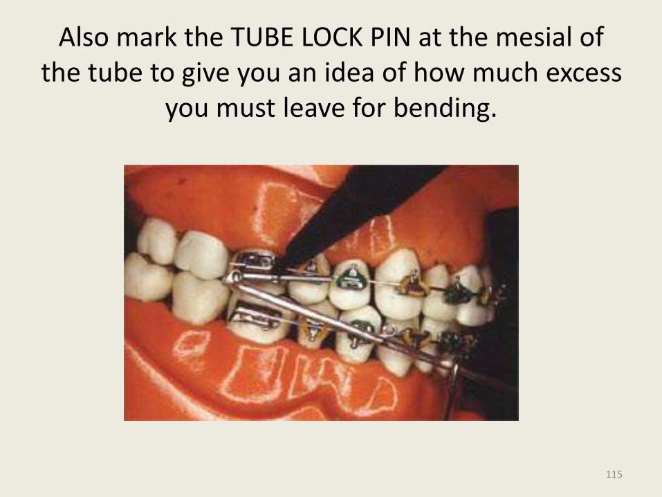
Also mark the TUBE LOCK PIN at the mesial of the tube to give you an idea of how much excess
you must leave for bending.
115
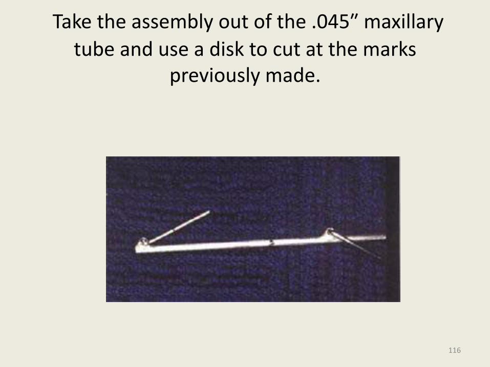
Take the assembly out of the .045″ maxillary
tube and use a disk to cut at the marks previously made.
116
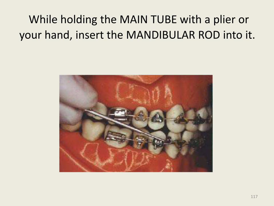
While holding the MAIN TUBE with a plier or
your hand, insert the MANDIBULAR ROD into it.
117
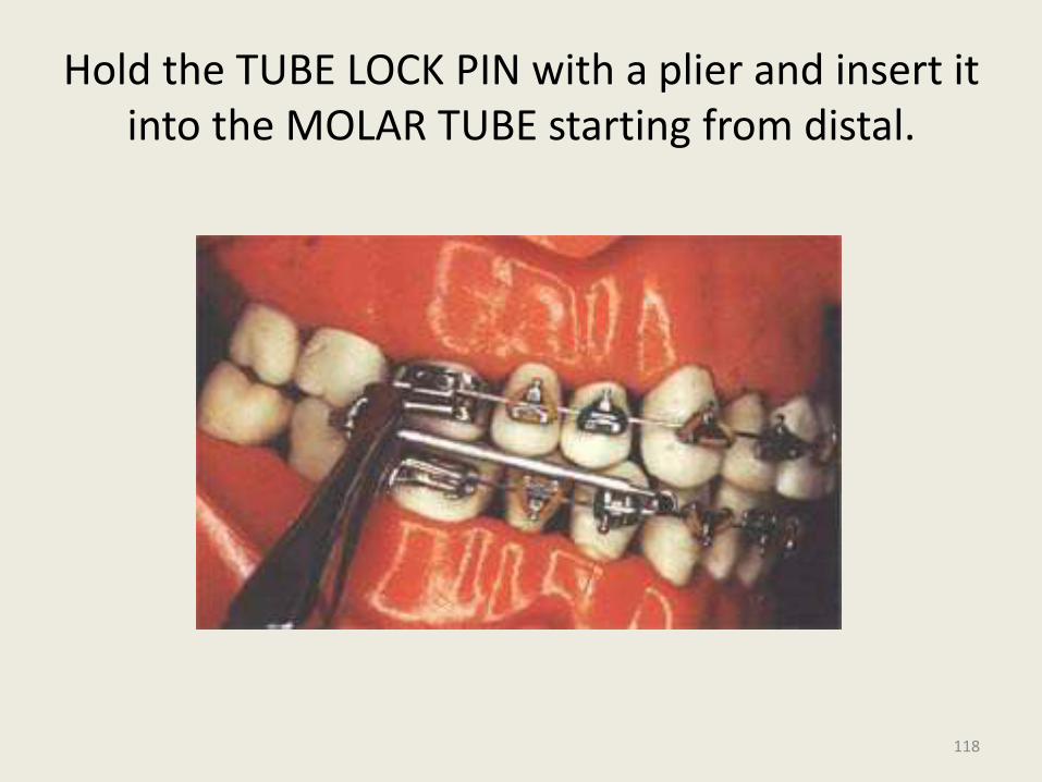
Hold the TUBE LOCK PIN with a plier and insert it into the MOLAR TUBE starting from distal.
118
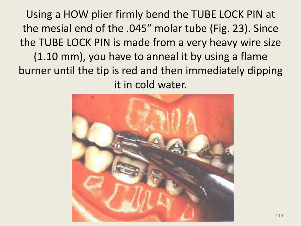
Using a HOW plier firmly bend the TUBE LOCK PIN at the mesial end of the .045″ molar tube (Fig. 23). Since the TUBE LOCK PIN is made from a very heavy wire size
(1.10 mm), you have to anneal it by using a flame burner until the tip is red and then immediately dipping
it in cold water.
119
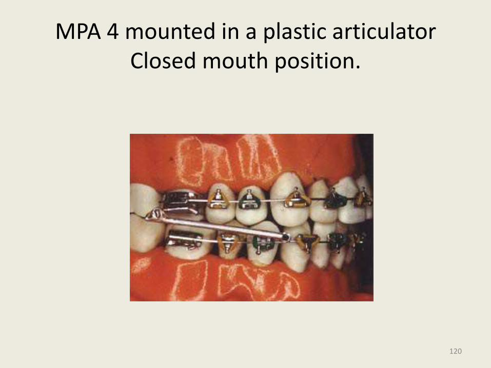
MPA 4 mounted in a plastic articulator Closed mouth position.
120
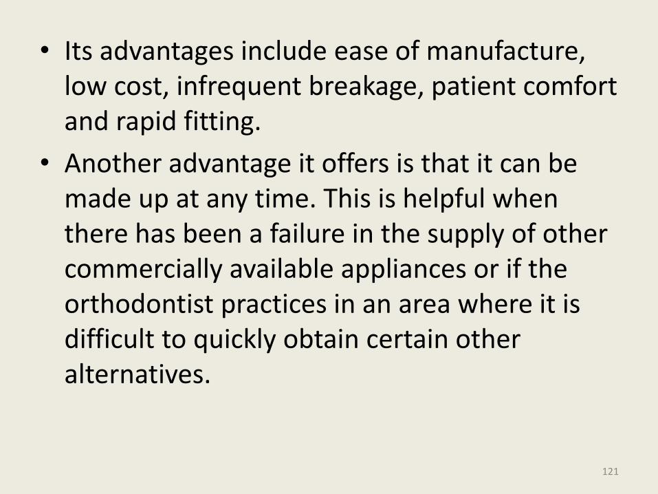
• Its advantages include ease of manufacture, low cost, infrequent breakage, patient comfort and rapid fitting.
• Another advantage it offers is that it can be made up at any time. This is helpful when there has been a failure in the supply of other commercially available appliances or if the orthodontist practices in an area where it is difficult to quickly obtain certain other alternatives.
121
Universal Bite Jumper
• Introduced by Xavier Calvez (1998)
• This is like a Herbst but is smaller in size and more versatile – it can be used in all phases of treatment in mixed or permanent dentition, Class II or III malocclusions.
• No laboratory preparation is required. It is fitted in the patient’s mouth and cut to the appropriate length for the desired mandibular advancement.
122
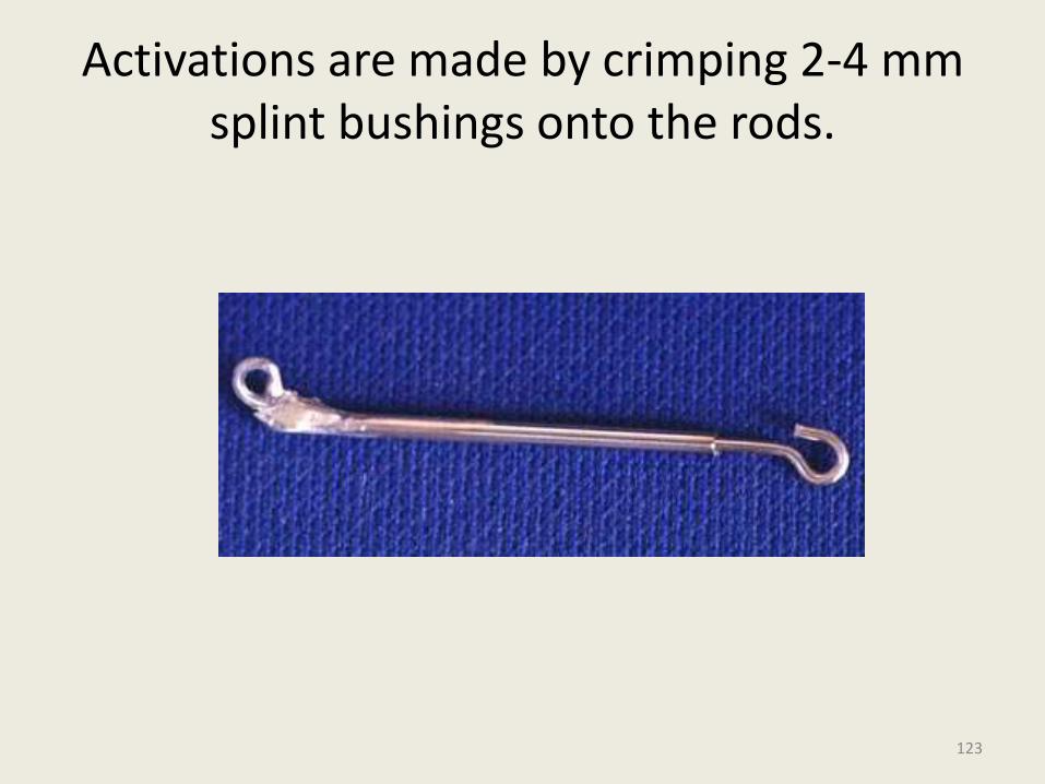
Activations are made by crimping 2-4 mm splint bushings onto the rods.
123
• This jumper also uses a telescoping mechanism, can also have an active coil spring if necessary.
• In its normal configuration, the UBJ is attached to the maxillary headgear tube with a ball pin which is bent so it can be tied with a ligature to the hook on the molar band.
• In the mandibular arch the sliding rod ends in a 90° hook that is fixed to the archwire.
• The premolars should be left free, while 0.022" brackets are banded from canine to canine.
124
THE MANDIBULAR ANTERIOR REPOSITIONING APPLIANCE (MARA)
• Is probably the most recent fixed functional appliance to become commercially available
• In the essence, it is an ingenious way to encourage patients to keep their mandibles thrust forward to avoid intentionally created, buccally placed occlusal interferences.
125
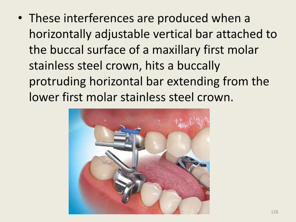
• These interferences are produced when a horizontally adjustable vertical bar attached to the buccal surface of a maxillary first molar stainless steel crown, hits a buccallyprotruding horizontal bar extending from the lower first molar stainless steel crown.
126
• Additional activations can be made by placing one or more shims at the mesial aspect of the horizontal bar. Advancing the mandible forward In precise increments can be achieved by insertion of selected shims of varying length
127
Advantages - Better esthetics• Problem with disengagement do not occur• Breakage from lateral mandibular movements
less.• Disadvantages• Temporary stainless steel crowns needed on all
first molars.• Some increase in anterior facial height results
from the placement of these crowns.• Fabrication only available at one commercial
laboratory.• The posterior and buccal location of the guide
planes may cause loosening of the stainless steel crowns or breakage of the mandibular protruding horizontal bar.
128

The Churro Bite Jumper
FLEXIBLE FIXED FUNCTIONALS
129
• The Churro Jumper furnishes orthodontists with an effective and inexpensive alternative force system for the anteroposterior correction of Class II and Class III malocclusions.
• Improvisation of the MPA .
• The resulting appliance is easily fabricated with materials commonly found in orthodontic offices and does not require any laboratory construction.
130
The name was taken from a Mexican cinnamon twist.
Although the Churro Jumper was conceived as an improvement to the MPA, it functions more like the Jasper Jumper.
131
In the Class II mode, each jumper attaches to the maxillary molars by a pin that passes first through a circle on the distal end of the jumper and then through the distal end of the headgear tube.
It is secured by bending the pin down on the mesial end of the tube
132
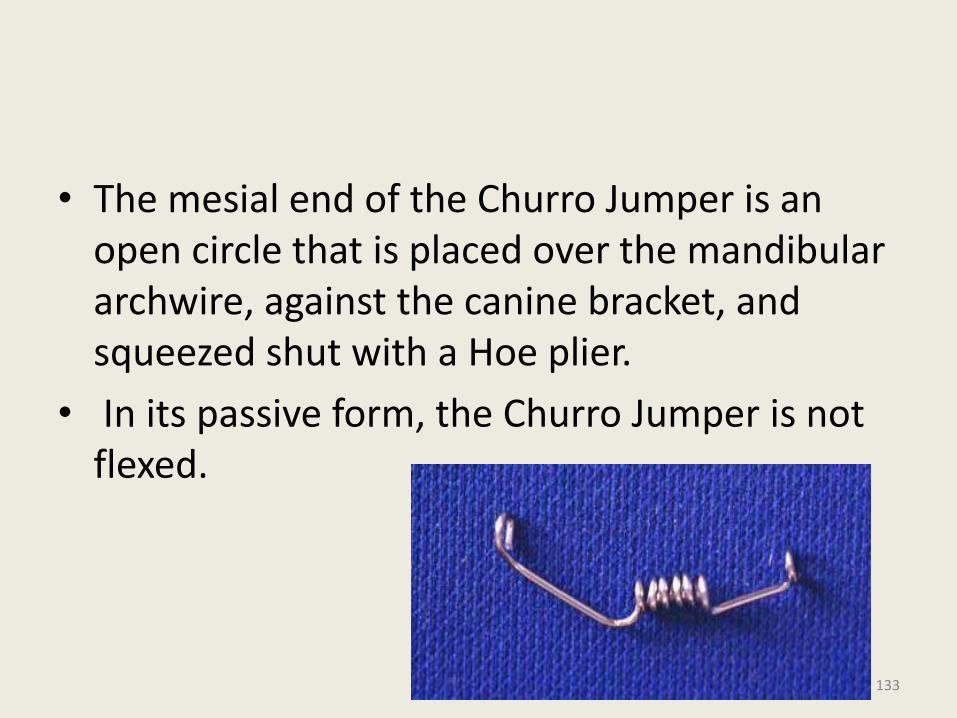
• The mesial end of the Churro Jumper is an open circle that is placed over the mandibular archwire, against the canine bracket, and squeezed shut with a Hoe plier.
• In its passive form, the Churro Jumper is not flexed.
133
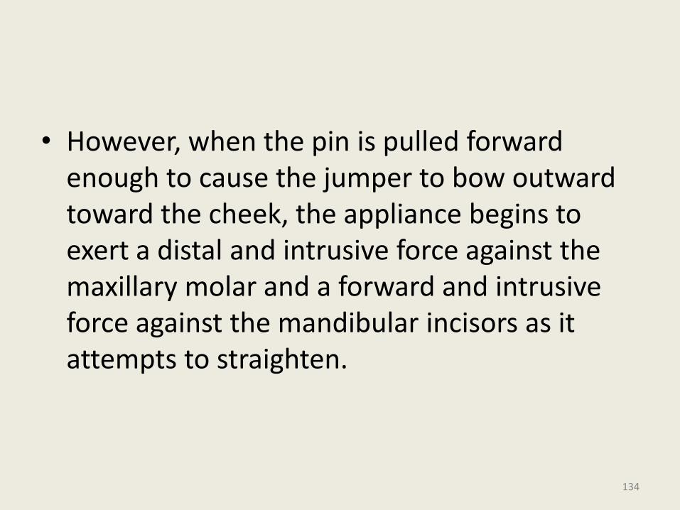
• However, when the pin is pulled forward enough to cause the jumper to bow outward toward the cheek, the appliance begins to exert a distal and intrusive force against the maxillary molar and a forward and intrusive force against the mandibular incisors as it attempts to straighten.
134
Construction
The Churro Jumper can be fabricated in a number of ways, as long as a series of 15-20 symmetrical and closely placed circles are formed in a wire. The wire size can be .028" to .032“
. A wire as large as .036" will be too difficult to work with, and anything smaller than .028" will not be strong enough to resist breakage.
The .030" wire has proven the most adaptable and useful of all the sizes tried. 135
Since the Churro Jumper requires reciprocal anchorage, an appropriate mandibular archwire is critical for its success in Class II cases. Generally, the largest possible edgewise archwire is the best to use.
It is important that the ends of the mandibular archwire be annealed and turned down distal to the terminal molars to act as tiebacks that will limit flaring of the mandibular incisors.
136
Because the Churro needs space to slide on the mandibular archwire, at least the first premolar brackets should be omitted.
It is usually advantageous to place a buccal offset in the wire just distal to the canine bracket so that the jumper also has buccal clearance, which permits unrestricted sliding along the wire .
137
Advantages
It provides a constant, indefatigable force that cannot be removed from the mouth.
• It can be used either unilaterally or bilaterally.
• It can be used to correct Class II or Class III malocclusions.
• It helps maintain anchorage, since it prevents the maxillary molars and mandibular incisors from moving into extraction sites.
138
• The cost of construction for materials and labor is less than $1.
• It is universal in size and can be adapted to fit any malocclusion.
• When broken, it is easily and inexpensively removed and replaced.
139
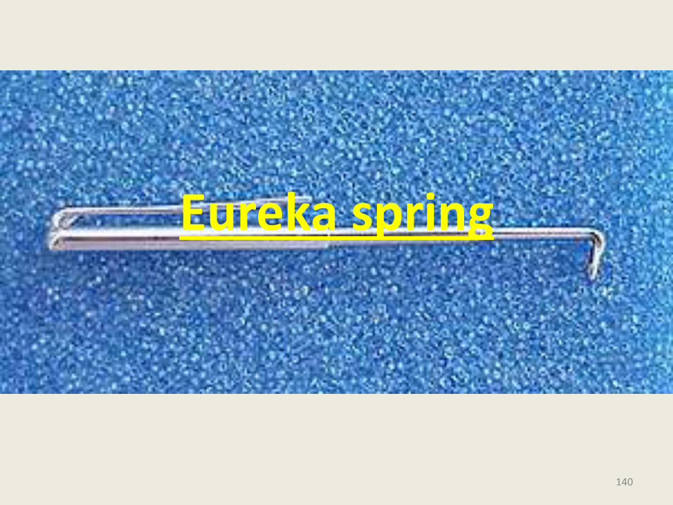
Eureka spring
140
This appliance appeared on the market in 1996 and it was developed by DeVicenzo and Steve Prins.
It is a three part telescopic appliance fixed to the upper arch at the level of the molar band and to the lower arch distal to the cuspid.
141
The appliance has an open coil spring that is placed inside of a part of the system.
Interestingly the authors caution in the manual that the appliance does not create any orthopedic effect, but underline that the correction is totally dentoalveolar.
The placement system is relatively simple.
142
• The patient can open his or her mouth widely without any difficulties due to the telescopic effect of the appliance.
• It is available in two sizes: 20 and 23 mm long. The Eureka spring comes in only 2 sizes one for extraction and one for nonextraction cases and left and the right sides are interchangeable.
• The appliance is universal and it can be applied both to the right as well as to the left side.
143
144
Advantages –
Ability to function without the need of patient co-operation.
Esthetic acceptability to patients.
Resistance to breakage.
High force values are delivered by Jasper jumper upto 280 gms; But this spring exerts140-170 gms.at the point of attachment.
145
It never functions in any other mode except for straight compression, which is evenly distributed over the entire length of the spring.
Ability to produce rapid movement.
It continues to work even when mouth is slightly open as during sleeping.
Low cost.
Promotion of good oral hygine.
146
The Klapper Super Spring
• Introduced by Lewis Klapper in 1997,for correction of class II malocclusions.
147
• On first glance, it resembles a Jasper Jumper with a substitution of a cable for the coil spring. In 1998 the cable was wrapped with a coil and the Klapper superspring II was the result.
• Only two sizes are required (left and right sides are not interchangeable) and breakage is less frequent. However it differs significantly from the Jasper Jumper at the molar attachment. The Klapper superspring II inserts from the mesial and is rigidly secured to the molar by an oval attachment tube.
148
• The Klapper superspring creates a distal root tip movement on the molar, this may be desirable in some patients:
• Because the Klapper superspring inserts gingivally on the molar and cannot roll to the buccal as readily as the Jasper Jumper, there may be a greater vertical component to the force vector, a pronounced curve of speeLevels faster.
149
• Disadvantages
• Requirement of a special molar tube
• Lack of adaptability to correct class III conditions
• Limitation to maximal opening
• Potential injury to the patient if breakage occurs and the rigid molar attachment forces the broken portion into the soft tissues.
• Extended wear may cause excessive root distal tipping to the maxillary molar and more intrusion at the molars and incisors than desired
150
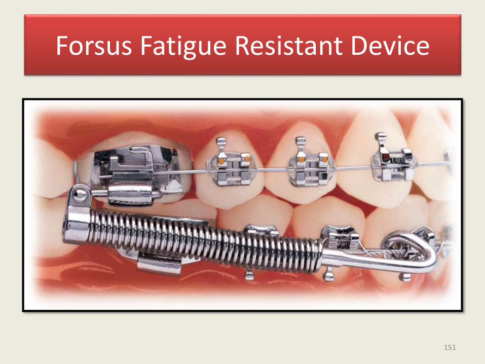
Forsus Fatigue Resistant Device
151
• The FRD is a threepiece, semirigid telescoping system incorporating a superelastic nickel-titanium coil spring that can be assembled chair-side in a relatively short amount of time.
• It is compatible with complete fixed orthodontic appliances and can be incorporated into preexisting appliances.
• The FRD attaches at the maxillary first molar and onto the mandibular archwire, distal to either the canine or first premolar bracket.
• As the coil is compressed, opposing forces are transmitted to the sites of attachment.
152
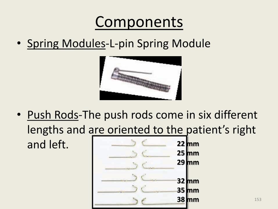
Components• Spring Modules-L-pin Spring Module
• Push Rods-The push rods come in six different lengths and are oriented to the patient’s right and left. 22 mm
25 mm29 mm
32 mm35 mm38 mm 153
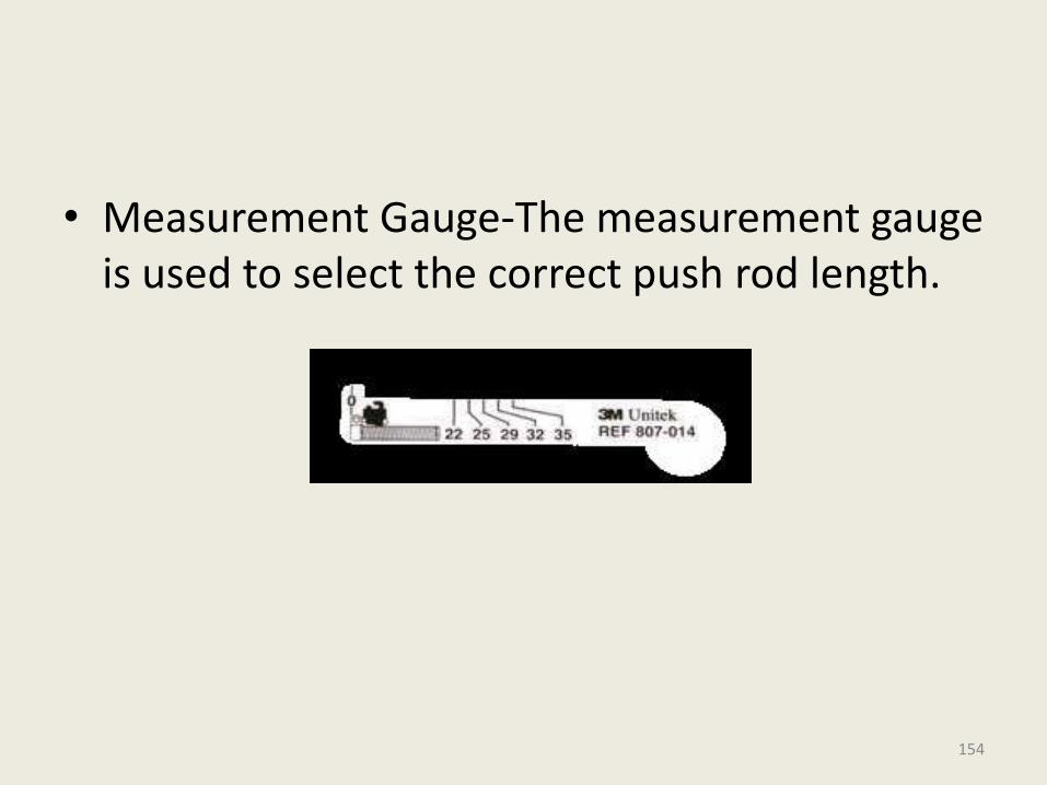
• Measurement Gauge-The measurement gauge is used to select the correct push rod length.
154
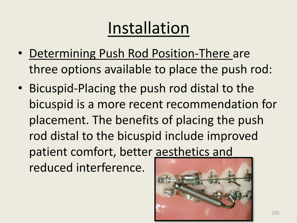
Installation
• Determining Push Rod Position-There are three options available to place the push rod:
• Bicuspid-Placing the push rod distal to the bicuspid is a more recent recommendation for placement. The benefits of placing the push rod distal to the bicuspid include improved patient comfort, better aesthetics and reduced interference.
155
• Because of the increased vertical angle, a lower first bicuspid installation can lead to more upper 1st molar intrusion and should be monitored for this possibility.
• Cuspid-
• The traditional location to place the push rod is distal to the cuspid.
156
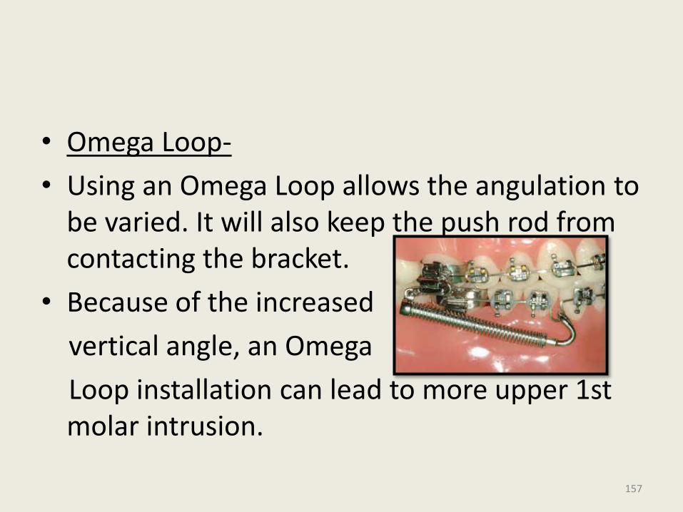
• Omega Loop-
• Using an Omega Loop allows the angulation to be varied. It will also keep the push rod from contacting the bracket.
• Because of the increased
vertical angle, an Omega
Loop installation can lead to more upper 1st molar intrusion.
157
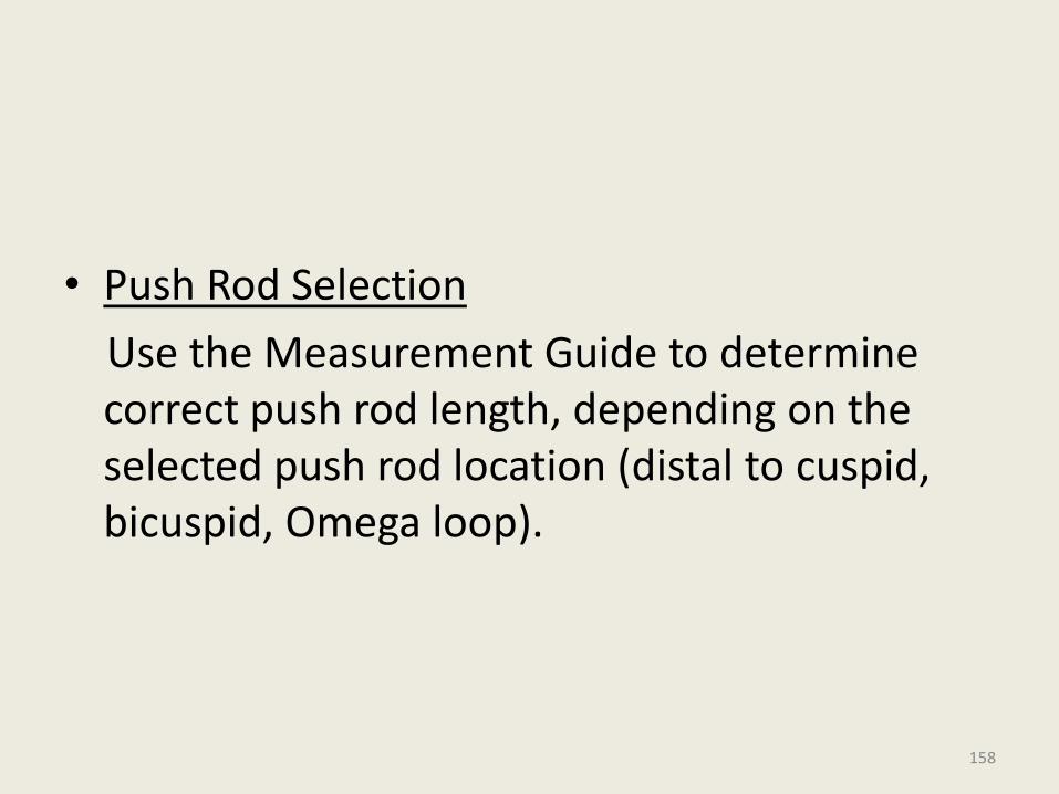
• Push Rod Selection
Use the Measurement Guide to determine correct push rod length, depending on the selected push rod location (distal to cuspid, bicuspid, Omega loop).
158
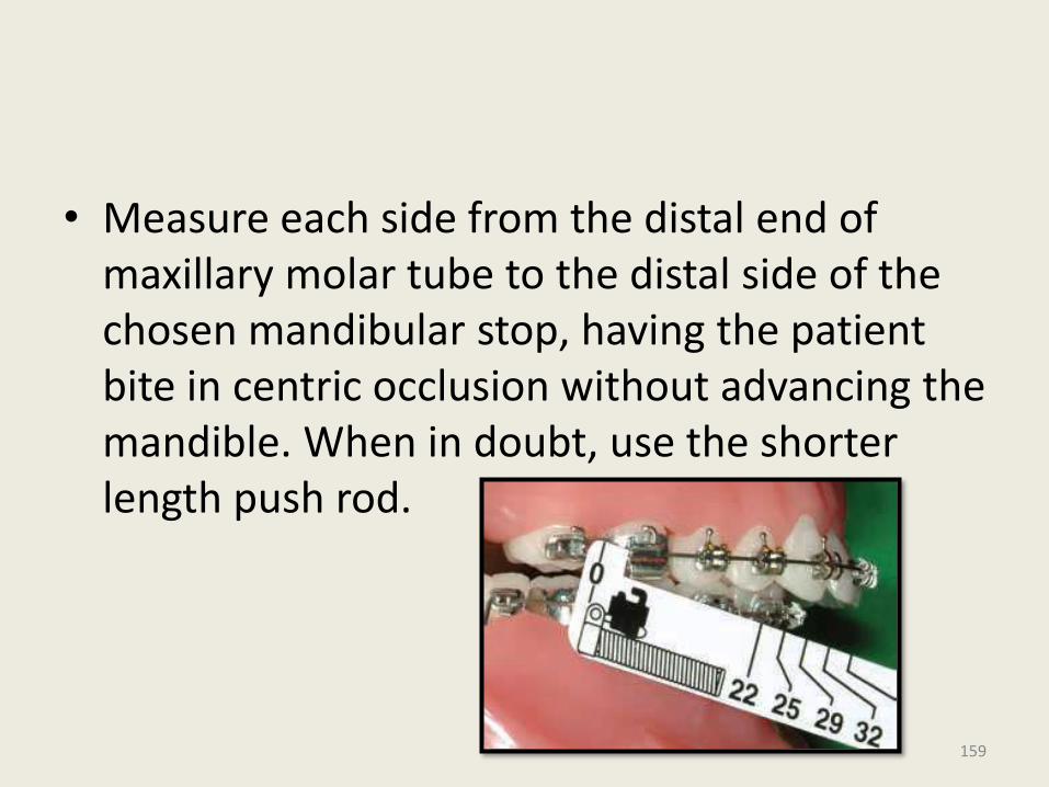
• Measure each side from the distal end of maxillary molar tube to the distal side of the chosen mandibular stop, having the patient bite in centric occlusion without advancing the mandible. When in doubt, use the shorter length push rod.
159
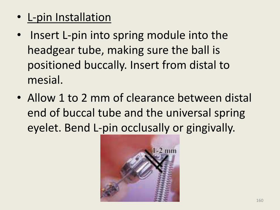
• L-pin Installation
• Insert L-pin into spring module into the headgear tube, making sure the ball is positioned buccally. Insert from distal to mesial.
• Allow 1 to 2 mm of clearance between distal end of buccal tube and the universal spring eyelet. Bend L-pin occlusally or gingivally.
160
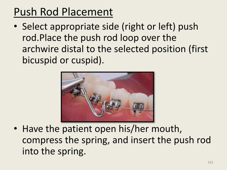
Push Rod Placement• Select appropriate side (right or left) push
rod.Place the push rod loop over the archwire distal to the selected position (first bicuspid or cuspid).
• Have the patient open his/her mouth, compress the spring, and insert the push rod into the spring.
161
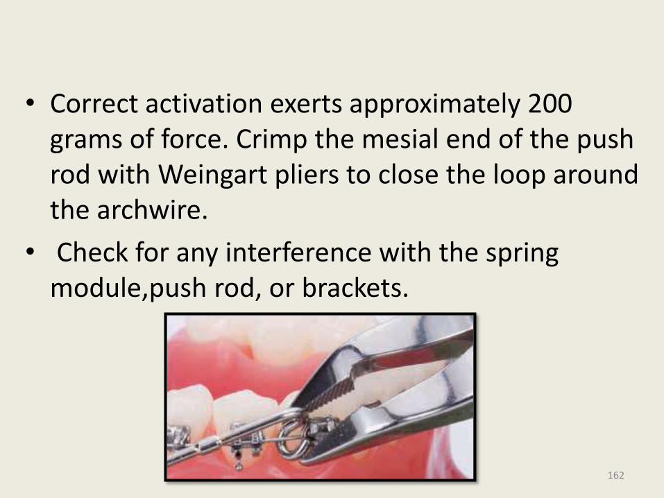
• Correct activation exerts approximately 200 grams of force. Crimp the mesial end of the push rod with Weingart pliers to close the loop around the archwire.
• Check for any interference with the spring module,push rod, or brackets.
162
Advantages • Easy Installation
• Patient-Compliance=minimized
• Consistent Forces=Correct activation of the module exerts approximately 200 grams of force. Forsus Correctors consistently apply light force as compared to intermittently applied forces, such as that offered by facebows
• Durable-fatigue resistant Ni-Ti coil spring
• Hygiene
163
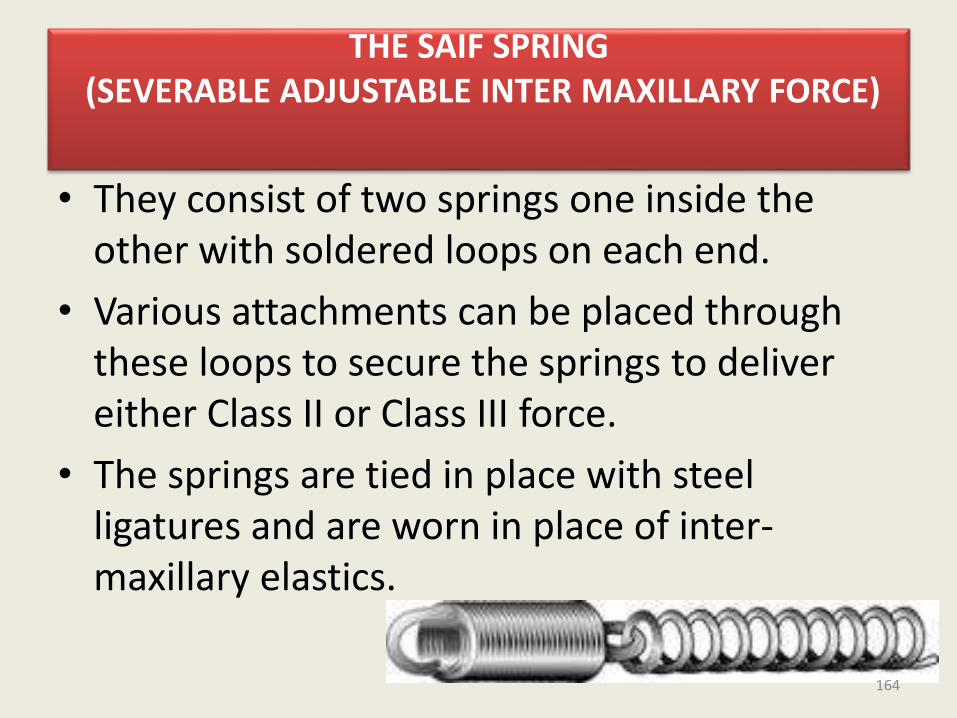
THE SAIF SPRING(SEVERABLE ADJUSTABLE INTER MAXILLARY FORCE)
• They consist of two springs one inside the other with soldered loops on each end.
• Various attachments can be placed through these loops to secure the springs to deliver either Class II or Class III force.
• The springs are tied in place with steel ligatures and are worn in place of inter-maxillary elastics.
164
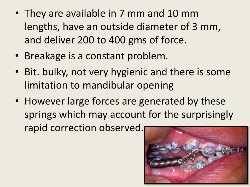
• They are available in 7 mm and 10 mm lengths, have an outside diameter of 3 mm, and deliver 200 to 400 gms of force.
• Breakage is a constant problem.
• Bit. bulky, not very hygienic and there is some limitation to mandibular opening
• However large forces are generated by these springs which may account for the surprisingly rapid correction observed.
165
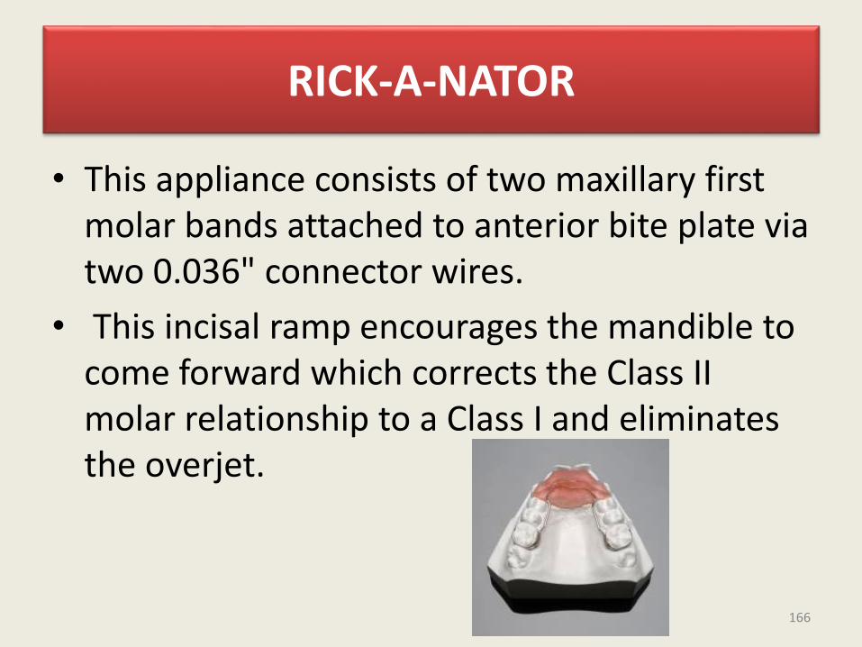
RICK-A-NATOR
• This appliance consists of two maxillary first molar bands attached to anterior bite plate via two 0.036" connector wires.
• This incisal ramp encourages the mandible to come forward which corrects the Class II molar relationship to a Class I and eliminates the overjet.
166
• Parts of Rick - A - Nator1. Two molar bands with lingual attachments
which could be
• a) Fixed (soldered)
• b) Mia attachment(mesial direction)
• c) Mershon attachment (vertical direction)
2. 0.036" connector wire from molar bands to incisal ramp.
3. Incisal ramp (clear acrylic)
167
• Tvpes of Rick - A- Nator
• When construction the Rick-A-Nator the clinidah must decide whether the appliance is to be fixed or fixed removable.
• a. Fixed attachment:
• The type has the 0.036" wires soldered directly to the lingual of the molar bands. One important advantage of this type is that the patient cannot remove the appliance and thus you are assured of 24 hours of wear time. Also with the fixed type there is Iess breakage and the appliance is more stable.
168
• b. Mia attachment:
• The female part of the Mia attachment is soldered to the lingual of the molar band. The male part is soldered to the 0.036" connector wire and fits into the female part from the mesial. After the molar bands are cemented, the appliance can easily be removed by the patient or the clinician in a mesial direction.
• The disadvantage with the fixed types are that if the patient wants to remove the appliance to eat or clean it, they cannot do so. Also, if the clinicianwants to remove the appliance to reline the acrylic, he first needs to remove the cemented molar bands.
169
• c. Mershon attachment
• The female part of the Mershon attachment is soldered to the lingual of the molar band. The male part is soldered to the 0.036" connector wire and fits into the female part from the vertical.
• This attachment enables the clinician to remove the appliance with relative ease but makes it more difficult for the patient. The appliance is removed in a vertical direction.
170
CONCLUSION
• So in conclusion, though fixed functional appliances have a track record showing proven efficiency, a correct diagnosis of the problem area in the class II malocclusion is paramount for successful treatment with fixed functional appliance.
• As Maslow said, If your only instrument is a hammer then every problem looks like a nail. If your only orthodontic tool for correcting class II malocclusion is a protractor then every class II seem like mandibular retrusion and clearly not everyone is.
171

• A complete understanding of possibility and limitations of the treatment will help the clinicians to avoid failures and disillusionment.
172

Thankyou
173


![Pain level between clear aligners and fixed appliances: a ......with fixed appliances, it is common to feel pain and dis-comfort [6], reaching its peak 24h after arch insertion, and](https://img.pdfslide.us/doc/110x75/5f88505305ea577cf73ee39c/pain-level-between-clear-aligners-and-fixed-appliances-a-with-fixed-appliances.jpg)