Embed Size (px)
Citation preview

32 Endovascular Brachytherapy
Richard Pötter, Erik Van Limbergen 1 Introduction Vascular stenosis - mainly on the basis of arteriosclerotic disease - represents one of the major problems in cardiovascular disease. Vascular stenosis contributes significantly to the clinical consequences of arteriosclerotic disease being the leading cause of death in western countries. The etiology of vascular disease is very complex and many factors have been implicated such as abnormalities of fat lipometabolism (elevated LDL-cholesterin), elevated blood pressure, and nicotine. The prognosis of stenotic vascular disease varies mainly with the location and extent of the disease, and is also dependent on accompanying diseases like diabetes and hypertension. Symptoms vary significantly with the location of the disease: angina and myocardial infarction from ischaemic heart disease in stenotic coronary arteries; intermittent claudication and ischaemic leg disease from peripheral arterial occlusive disease; psychoneurological disorders, transient ischemia and stroke from carotid and cerebral arterial occlusive disease. Vascular bypass surgery was the treatment of choice until the introduction of Percutaneous Transluminal Coronary Angioplasty (PTCA) in 1977 by Grüntzig. Since then, interventional procedures have been increasingly used, in particular in coronary arteries, but also in peripheral arteries (PTA), in renal arteries and recently also in carotid arteries. Whereas the overall primary success rate of these procedures is reported to be above 90%, the long term success rate is much lower. Long term success is often achieved by the additional implantation of a stent, in particular in coronary arteries. Restenosis in native or stented arteries occurs in a significant number of patients, the specific rates are dependent on various risk factors (e.g. in-stent restenosis, long lesions, small arteries, diabetic patients) and for coronary arteries are from 10% to 60%. Therefore, restenosis has become one of the major problems in the treatment of stenotic vascular disease, and many attempts have been made to overcome the process of it. Endovascular implantation of stainless steel stents reduces restenosis after coronary angioplasty of lesions shorter than 10 - 15 mm but does not reduce restenosis after femoro-popliteal angioplasty. Such stents do not limit neointimal proliferation. The decrease in restenosis rate is achieved by creating a larger postangioplastic vessel lumen. Preventive drug therapy, consisting of anticoagulants, antiplatelet agents, steroids, ACE inhibitors, somatostatin analogs, platelet derived growth factor inhibitors and locally delivered monoclonal anti-platelet antibody has been tried. None of these pharmacological interventions have decreased the restenosis rate and no drug has yet been recognised which prevents restenosis. Gene therapy, although challenging, has not yet had any impact in reducing restenosis rate in humans. The development of new interventional techniques such as directional atherectomy, rotary ablation and laser angioplasty has also failed to successfully reduce the restenosis rate. The use of photodynamic therapy and targeted chemotherapy for prevention of restenosis is still in an early experimental phase.

636 Endovascular Brachytherapy
Trials using radioactive stents have been faced with the major problem of “edge effect” which was probably due to radiation under-dosage at the edge of the stent. Many problems were also seen with balloons filled with radioactive liquid. A recent approach with chemotherapy coated stents seems to be very promising according to early trial results. As these procedures are still in an experimental phase, they are not dealt with here in detail, although in principle they present interesting alternatives. In the 90ies catheter based brachytherapy systems (gamma and beta) were introduced into clinical practice and after evaluation in several randomised prospective clinical trials, have been proven to be safe and efficient in the prevention of (in-stent) restenosis and superior to angioplasty procedures alone. Therefore, for the foreseeable future, vascular brachytherapy may play a major part in a significant number of angioplasty procedures in patients with a significant risk of restenosis (5). Up to 12/2001 more than 30.000 patients had been treated by intravascular brachytherapy worldwide. 2 Vascular Anatomy and Pathology of Arteriosclerotic vessels The diameter and shape of arteries vary considerably throughout the vascular system. Coronary arteries (diameter of proximal arteries 2.5 - 5 mm) represent a branching system of mildly to significantly tortuous vessels lying on the outer surface of the heart. The Left (LCA) and the Right Coronary Artery (RCA) originate from the aortic root outside the aortic valve. The LCA bifurcates soon after its origin (a few centimetres) into the left anterior descending (LAD) and left circumflex (LCX) arteries. Angioplasty is usually not performed in arteries less than 1.5 mm. Femoropopliteal arteries (diameter 5 - 6 mm) are rather straight and take a typical course with several branches from the groin towards the popliteal fossa together with the vein and the femoral nerve. Arteries have a tubelike structure. The lumen is covered by endothelium, and then there is a subendothelial layer of connective tissue, which is the intima consisting of flattened longitudinally orientated cells (about 0.25 mm thick). An elastic layer, the internal elastic membrane, surrounds the intima. A relatively thick layer of smooth muscle cells and elastic tissues forms the media (about 1 mm), which has more elastic tissue in larger vessels and more smooth muscle cells in smaller vessels. The external elastic membrane forms the outer layer of the media. The adventitia (about 0.5 mm, no clear outer margin) forms the outmost layer of the artery, consisting mainly of collagenous fibers, and in addition some myofibroblasts. In atherosclerosis, plaques reduce the arterial lumen, which compromises blood flow and oxygen delivery. The plaque formation starts in the intima with fatty debris from the blood. Collagen and fibrin are produced in the media by smooth muscle cells and are accumulated in the intima; later platelets and cholesterol adhere to the overlying endothelium and lipids accumulate in the intima. This is the start of a fibrous plaque, which may finally suffer hemorrhages, may be calcified and may lead to platelet aggregation and thrombosis with its various consequences from blood flow reduction, e.g. ischaemic heart disease. The plaque formation may lead to concentric arteriosclerotic vessels or more often to eccentric vessels.

Endovascular Brachytherapy 637
Fig 32.1: Schematic drawing showing the cross-section of an arterosclerotic artery. 3 Vascular Pathology: Development of Restenosis and the
Mechanism of Action of Radiotherapy 3.1 Pathology of restenosis In PTA/PTCA, the stenotic segment of the artery is dilatated using a special balloon catheter with pressure inflation from 14 - 18 atmospheres. This overstretching leads to a fracture of the atherosclerotic plaque and to significant damage in the different parts of the vessel wall (intima, media, (adventitia)), which may even result in a dissection of the wall at the time of intervention. The vessel wall with all its components has a complex reaction pattern to these injuries, which is partly similar to the complex wound healing process in other tissues (e.g. scar formation in the skin): * Neointimal proliferation. In reaction to the injury, platelets are deposited at the site of the lesion, forming a thrombus. Various cells are activated within hours (endothelial cells, platelets, smooth muscle cells) producing growth factors such as Interleukin, Platelet Derived Growth Factor (PDGF), and TGF beta. Within a few days, also mediated through activated Macrophages and T-Lymphocytes, this process leads to the activation of smooth muscle cells, myofibroblasts, and fibroblasts. Production of extracellular matrix is also activated. All these reactions finally lead to proliferation, migration, and differentiation of smooth muscle cells (media) and myofibroblasts (adventitia). Within weeks to months these cells migrate into the inner intimal layer of the vessel and form the “neointimal proliferation”. This process begins within days after angioplasty and continues for weeks and months. The reduction in synthesis of EDRF (Endothelium Derived Relaxing Factor) due to endothelial injury may also contribute to neointimal proliferation. The result of this neointimal proliferation is a severe reduction of the artery diameter. The whole process seems to be completed within 3 - 8 months. For a comprehensive understanding of the process of restenosis, two further mechanisms after PTA/PTCA must be considered: * Elastic recoil or shrinking of the artery occurs soon after dilatation of the artery. Recoil occurs within minutes and hours after angioplasty and leads to a loss of up to 50% of the vessel diameter, especially in the part of the vessel that was not arteriosclerotic before angioplasty. Elastic recoil cannot take place in stented arteries.

638 Endovascular Brachytherapy
* Remodelling. After the PTA/PTCA injury the entire artery becomes more and more constricted and may shrink significantly; this mechanism is called “unfavourable remodelling”. In contrast, the artery may expand in response to neointimal formation which is called “favourable remodelling”. Restenosis is angiographically defined as narrowing of the lumen equal to or exceeding 50% of the lumen diameter compared to the normal arterial segments. 3.2 Mechanisms of radiation for the prevention of restenosis It has been long recognised, that ionising radiation reduces cell proliferation by damaging the DNA in the nucleus through various mechanisms. For a significant time period, this paradigm formed the basic understanding of how radiotherapy works in malignant and benign disease (mechanism of action of radiotherapy). This process provided the rational for the commencement of vascular radiotherapy, which was introduced to prevent vascular restenosis after angioplasty based on knowledge of the antiproliferative effect of radiation on excessive scar formation after excision of keloids (1). Fig 32.2: Schematic Diagram of the Process of Elastic Recoil, Neointimal Proliferation, Remodelling and the impact of radiotherapy on these processes Experimental studies in animals confirmed the first positive clinical experience, showing a significant reduction of neointimal proliferation in the irradiated arteries following different angioplasty-like procedures. Both beta and gamma radiation showed similar effectiveness in different animal models (e.g. in the iliac artery in the rabbit (12) and in the coronary artery in the pig (14)). From the

Endovascular Brachytherapy 639
beginning, a dose response effect was observed: the most pronounced effect was reported between 14 and 20 Gy. Further experimental investigations showed that the target is not the intima itself, but rather a mix of the different cell populations of the adventitia/media, which seem to be relevant for the mechanism of action of radiotherapy. These are the macrophage, the T-lymphocyte, the smooth muscle cell, the fibroblast, and the myofibroblast, which are inactivated through radiation in different ways. In the very beginning of this process, the decrease in production of growth factors and maybe extracellular matrix seems to play a major role. Later, migration and proliferation of smooth muscle cells are significantly reduced. The decrease in the production of extracellular matrix helps to explain the effect of “favourable remodelling”, which is seen as a positive late effect in irradiated arteries after angioplasty. 4 Work Up
The work up is done by the clinician responsible for the diagnosis and treatment of vascular disease. The indication for an angioplasty procedure is based on different forms of clinical, laboratory and technical examinations and mainly on findings from angiography within the given clinical setting. In coronary vascular disease, these examinations include the patient´s history focussed on symptoms from ischaemic heart disease (e.g. angina), electrocardiogram, echocardiogram, scintigraphy, and certain laboratory tests. In peripheral arterial disease, examinations include the patient`s history focussing on typical symptoms (e.g. walking distance without pain), a specific clinical examination of the leg, ankle brachial index, a colour duplex sonography (doppler ultrasound), and the peak velocity ratio (doppler ultrasound). The specific work up for intravascular brachytherapy includes mainly intraarterial angiograms (film as hard copy or as video) before, during and after the angioplasty procedure indicating the length of the lesion, the length of the segment in which angioplasty has been performed and the vessel lumen diameter which is determined before and after angioplasty. If a stent was introduced, this is also demonstrated on the angiogram. In addition, intravascular ultrasound (IVUS) may be used, if available, to obtain information about the topography and pathology of the vessel wall (e.g. plaque location and configuration) before and/or after angioplasty. Percutaneous ultrasound (Doppler) is routinely applied in peripheral arteries. 5 Indications, Contra-indications
For coronary artery disease, indications vary depending on the clinical setting, according to the different risks of restenosis. The methodology of investigations also varies resulting in different levels of evidence, with the highest evidence derived from prospective randomised double blind clinical trials. In-stent restenosis carries a high risk of further restenosis and now represents a proven indication for endovascular brachytherapy (FDA approval for this indication was achieved in 2000). Data was first collected from trials with gamma sources, but recently also from large trials with beta sources. The

640 Endovascular Brachytherapy
situation is similar for in-stent restenosis in saphenous venous grafts, although the body of evidence is much smaller. There is evidence, mainly from subgroup analysis in randomised trials, that in the following situations, which carry a high risk of restenosis, intravascular brachytherapy may be indicated: de novo-long lesions, de novo-small vessels, de novo lesions in diabetic patients, aorto-ostial lesions, bifurcation lesions, multivessel PTCA. There is some evidence that the risk of restenosis in non stented arteries may present a reasonable indication for intravascular brachytherapy as well as in non stented saphenous vein grafts. However, the risk of restenosis in these settings is considerably lower than for in-stent restenosis. In any clinical setting where the expected restenosis rate is low, the benefit from intravascular brachytherapy will be small, if it exists at all. The indication in such situations therefore has to be very carefully considered. Relative contraindications are prior radiotherapy to the chest for treatment of cancer or restenosis in a vessel segment that has been previously treated by intravascular brachytherapy to a significant dose. In femoropopliteal arteries all restenotic lesions and de novo-lesions with a high risk of restenosis are indications for intravascular gamma brachytherapy. At present, these are mainly long lesions (>>5 cm), lesions in diabetic patients, and primarily occluded vessels. Relative contraindications are failures from previous intravascular brachytherapy.
Level of evidence Indication of endovascular BT
Supported by randomized trials In-stent restenosis
Supported by subgroup trial analysis Saphenous-venous graft in-stent restenosis
Restenosis in non stented arteries
De-novo lesions with high risk for restenosis
No data, relative contraindication Failed EVBT, prior chest RT
Table 31.1: Indications and Contraindications for endovascular coronary brachytherapy related to the level of clinical evidence.
6 Target Volume There is little consensus at present about the precise target for radiation to prevent restenosis. However, there is sufficient experimental evidence to state that the intimal layer clearly does not represent the main target for intravascular radiation. Most data indicate that the target consists of some cell system(s) located in the adventitia, maybe partly also in the media, which play a major role in the development of restenosis. Target definition is mainly based on angiograms performed during and after angioplasty. There is some uncertainty and consequently some variation in defining the target depth. The definition may follow general rules for certain clinical situations indicating a certain depth in the

Endovascular Brachytherapy 641
coronary or in the femoropopliteal artery and taking into account in addition the vessel lumen diameter. Such a procedure is usually mainly based on angiograms. It may also follow individualised dose prescription, looking case by case into the topography and pathology of the vessel segment to be treated by radiotherapy (9). This procedure is usually based on IVUS. It may also take into consideration whether a centring or non centring device is used for radiotherapy. Fig 32.3: Radial dimensions in endovascular brachytherapy: definition of the reference depth dose point and reference lumen dose point (based on angiography) (Pötter et al. (5)): A: Schematic diagram of a vessel along the longitudinal dimension based on angiography: Reference Depth Dose (Point) (RDD(RDDP)) and Reference Lumen Dose (Point) (RLDo (RLDP)) as a function of the Radius (R) defined at the Reference Lumen Diameter (RLDi) plus the Reference Depth (RD) in the central plane of the Planning Target Length (PTL). The distance between the source position and the RDDP (SRD = R + RD) is taken for calculation of the RDD. The RD is 1 mm in coronary arteries and 2 mm in peripheral arteries. In non-centred systems the RDD is calculated in the same way assuming a centred position of the source as R(RLDi) + RD in the central plane. In addition, the maximum and minimum dose levels have to be added for the position of the source close to the vessel wall, both related to the RLDP and the RDDP.
B: Schematic diagram of a vessel cross-section based on IVUS with angiographic parameters superimposed. Reference Depth Dose Point (RDDPc) for coronary arteries based on the Reference Lumen Diameter (RLD) plus 1 mm, given in the central plane. In addition, the dose at the surface of the RLD is indicated in the same plane, which is the Reference Lumen Dose Point (RLDPc).

642 Endovascular Brachytherapy
Independently of the dose prescription procedure chosen, the following procedure is recommended (ESTRO recommendations 2001 for recording and reporting a reference depth in an unambiguous and reproducible way (5)). The distance of the reference depth dose point (RDDP) to the source centre should be calculated by indicating a certain radial reference depth (RD) from the vessel lumen into the vessel wall perpendicular to the vessel axis. Usually, in typical anatomical situations, this is given as 1 mm for a coronary and 2 mm for a femoropopliteal artery. In order to arrive at a reference depth dose point, the respective half reference lumen diameter (RLD/2) as defined after angioplasty must be added to this distance. Distance to the RDDP = RLDi/2 + RD The target length should always be significantly longer than the length of the lesion. The target length is first based on the interventional length (IL), which is defined as the angioplasty length of PTA or PTCA. This interventional length must include all positions in the vessel of the device, by which the angioplasty intervention was performed leading to vessel injury. This will be a balloon, a stent, mechanical debulking instrument, or any other method used to clear the vessel lumen. Fig 32.4: Schematic diagram for the definition of lengths in endovascular brachytherapy. LL: Lesion Length; IL: Intervention Length; CTL: Clinical Target Length; PTL: Planning Target Length; ASL: Active Source Length; RIL: Reference Isodose Length

Endovascular Brachytherapy 643
The clinical target length (CTL) must secondly include every injured part of the vessel. The injury caused by the intervention may often extend beyond the position of the device (as demonstrated on the angiogram), which serves as the basis for the definition of the IL. As radiotherapy is given to prevent the process of neointimal proliferation taking place in all the injured parts of the vessel, all this injury must be included. Because in an individual case, the precise definition of the margin to be added to the interventional length for additional injury is often difficult to determine, it may be arbitrarily chosen (e.g. 1 - 2 mm on each side). Finally, for the definition of the Planning Target Length (PTL), a safety margin must be added, which depends on the geometrical uncertainties of the radiation treatment which are patient and treatment device related. These uncertainties may be due to patient movements (e.g. heart beats) or to catheter positioning uncertainties and margins may be chosen in the range of a few mm on each side. In summary the Planning Target Length is obtained by adding the following safety margins (sm):
PTL = IL + sm (overall) sm = sminj (additional injury) + smgeom (geometrical uncertainties)
In coronary arteries a minimum overall sm of 5 mm each side is recommended, in femoral arteries 10 mm. 7 Technique 7.1 Design of devices for intravascular brachytherapy In the design of devices for intravascular brachytherapy, the dimensions of sources and catheters have to be small to permit treatment of thin arteries and for bending around tight curves. If a single source is used, it must be very precisely moved during treatment to achieve the projected dose distribution. An individual matching of the irradiated length to the target length is possible (stepping source technology). Wires or serial sources can be used without movement of the source during treatment, but these devices become stiffer and more difficult to position, especially in vessels which bend. The wire must be flexible enough to follow smoothly the curves of the guiding catheters. An adaptation in length in these cases is only possible by manufacturing wires or serial sources of different lengths. 7.1.1 Femoropopliteal arteries The brachytherapy device consists of a remote-controlled afterloader unit (e.g. microSelectron-HDR afterloader) which delivers gamma radiation with an Iridium-192 source safely and reproducibly. Such devices are already well known and widely available for HDR brachytherapy of cancer. The positioning of the source is computer controlled and initiated and controlled from outside the treatment room. The device has a safe to store the source when it is not in use. The afterloader is operated by programming the different source positions and dwelling times with the support of integrated libraries. These libraries can be modified by a Treatment Planning System attached to the afterloader unit. The source has a nominal activity of 370 GBq and is sealed in a stainless steel capsule with an Active Source Length of 3.5 mm and an outer diameter of 1.1 mm, which is welded to an ultraflexible part of a flexible cable driven from the afterloader. Due to the high activity of the source, treatment must be performed in rooms with specially shielded walls as are usual in HDR brachytherapy units.

644 Endovascular Brachytherapy
The source is moved along the target in the forward direction in step sizes of 5 mm. The step positions and dwelling times can be arbitrarily chosen and are indivually determined based on the target to be treated. A semiflexible 5F lumen catheter (1.65 mm outer diameter) with a closed tip is available (Nucletron), and has been in use for intraluminal brachytherapy (e.g. bronchus) for a long time. Such a catheter is introduced into a 6F sheath positioned in the vessel after angioplasty. There is no significant centring effect achieved by this catheter system. A specific centring balloon catheter for femoropopliteal arteries is available (PARIS Centering Catheter, Guidant). This multiple balloon catheter system is bilumnal, one lumen for the inflation (4 atmospheres) of the balloon (size: 4,5,6,7,8 mm, length of all balloons 10 or 20 cm), and one lumen to carry the closed-end radiation sheath and guide wire for catheter insertion, respectively. The catheter shaft diameter is 7F. A radio-opaque marker is integrated, indicating the most distal source position possible. Fig 32.5: Nucletron System for brachytherapy in femoropopliteal arteries in clinical use: HDR afterloader, PARIS catheter in place attached to the afterloader; inflating device connected to the PARIS catheter; introducer sheath in the groin. 7.1.2 Coronary arteries 7.1.2.1 The Cordis Checkmate™ Intravascular Brachytherapy System (Gamma) This device uses a hand-cranked lead container for mechanically advancing and retracting a radioactive 192Ir source ribbon to the distal end of the delivery catheter. The leaded Containment Device is for shielding the source during transportation and storage of the source. A lock mechanism secures the wire in place after positioning it in the target. The radioactive sources are 192Ir seeds (Best Industries) with an activated Ir/Pt wire encapsulated in a stainless steel capsule with a nominal length of 3 mm and a diameter of 0.5 mm. For coronary brachytherapy there are three configurations of ribbons housing 6, 10 or 14 seeds with 1 mm spacing and radio-opaque markers at each end in a 0.030-inch (0.762 mm) outer-diameter nylon sheath yielding 23 mm, 39 mm or 55 mm ASL, respectively. The maximum activity per seed is 1.2 GBq. To maintain short dwell times, the sources are exchanged approximately every 4 weeks. The Cordis intravascular radiation therapy (IRT) delivery catheter is a non-centred, single lumen, rapid exchange catheter with a closed ended source lumen. The outer diameter of the distal catheter

Endovascular Brachytherapy 645
shaft is 3.7F (≈ 1.2 mm). Each delivery catheter is provided with a “Uni-Dummy” ribbon containing 22 nonradioactive seeds for supporting the IRT catheter during insertion into the patient, assisting in positioning the catheter across the treatment site and as a tool to verify that the source lumen is un-obstructed prior to introduction of the active ribbon. Such catheters have been and can also be used for manual loading. Fig 32.6: Cordis Checkmate System for gamma intracoronary brachytherapy in the cath lab. The device is located on the mobile cart close to the operation table. The proximal part of the delivery catheter is connected to an adapter on the front side of the system, the distal part is placed in the artery. 7.1.2.2 The Guidant Galileo™ Intravascular Radiotherapy System (Beta) The source delivery unit is a computer-controlled afterloader with touch-screen operation and software to calculate the appropriate treatment time based on the prescribed dose and the reference lumen diameter. It is equipped with multiple safety features and emergency “STOP” buttons. The radioactive source wire is stored and shielded in an exchangeable cartridge inside the delivery unit. The source wire contains a pure, beta-emitting, solid isotope P-32 in a 0.018 inch (0.46 mm) Nitinol hypotube. The Active Source Length (ASL) is 20 mm which is indicated by two radio-opaque tungsten markers. Maximum activity at the time of treament is up to 10 GBq. The source delivery unit performs automated stepping of the source 2 or 3 times for treatment with an ASL of 40 or 60 mm, respectively. An inactive dummy wire is included in the delivery unit for detecting a kink or obstruction inside the delivery catheter and to establish proper positioning of the wire at the distal catheter marker. The centering balloon catheter is available with balloon diameters of 2.5 mm, 3.0 mm and 3.5 mm thickness and 32 mm or 52 mm nominal length. This length is marked by two radio-opaque markers indicating a length between RIL and maximum IL. The catheter key for connecting the device to the afterloader is coded with the length and diameter, enabling the delivery unit to identify these treatment parameters. The source lumen is centered by inflating a helical balloon with 4 atmospheres, allowing for some distal and side branch perfusion during the radiation treatment.

646 Endovascular Brachytherapy
Fig 32.7: The Guidant Galileo System during irradiation of a coronary vessel. The delivery catheter is connected to the front side of the system. A touch-screen is indicating the treatment parameters and the remaining dwell time. 7.1.2.3 The Novoste Beta-Cath™ Intracoronary Beta Radiation System The delivery unit for the radioactive Sr-90/Y-90 source train consists of a quartz source container for shielding and a hydraulic system, operated by an external syringe. Source delivery is manual. The delivery unit is equipped with electronic interlocks for safety and lead indicators for optimal fluid pressure and location of the sources. Due to the half life of 28 years, replacement of sources due to source decay is not necessary. However, for maintenance and update of the device by the manufacturer, there is an exchange of sources twice a year. Two devices containing source trains are available with 12, 16 or 24 seeds, each 2.5 mm resulting in an ASL of 30, 40 or 60 mm. The solid Sr-90/Y-90 mixture is encapsulated in a seed cylinder of 0.64 mm outer diameter with an activity of 0.13 GBq each. Additionally, there are two radio-opaque gold seeds at each end of the source train.
Fig 32.8. The Novoste BetaCath System is used by manual fluid pressure using a syringe fixed to the delivery device. The delivery catheter is connected with a lock system. When not in use the sources are located in a safe and are visible through a shielded window.
Endovascular Brachytherapy 647
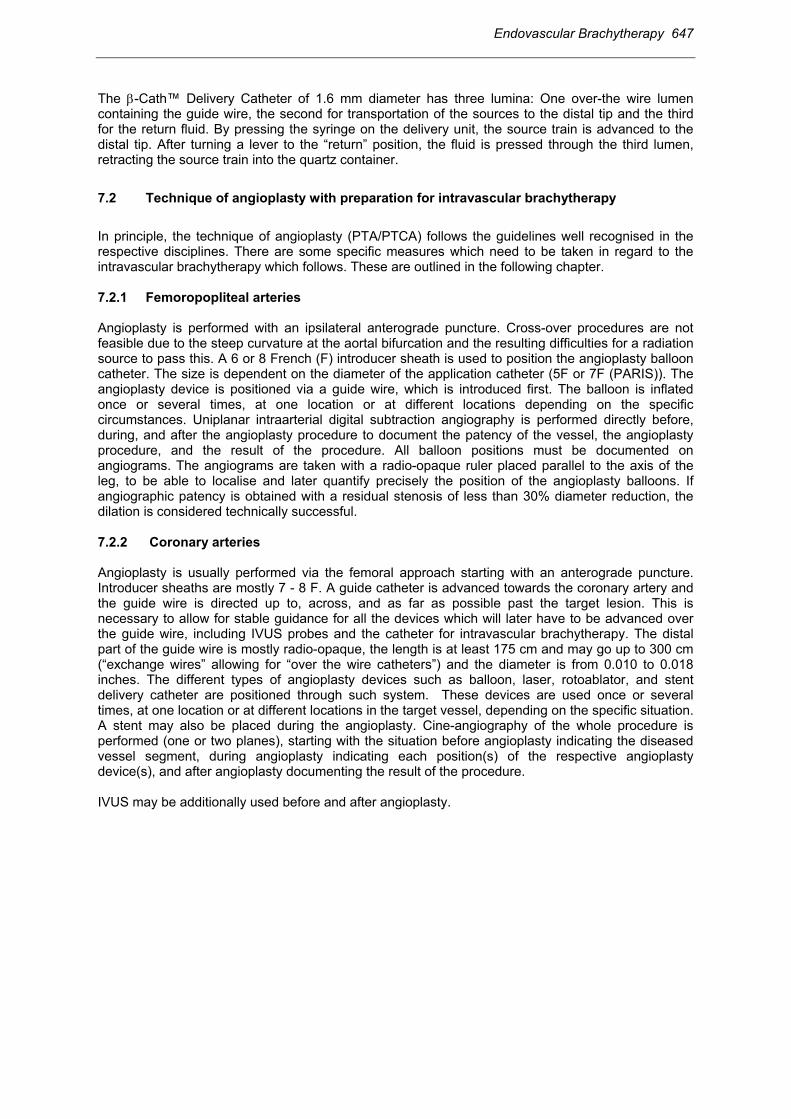
The β-Cath™ Delivery Catheter of 1.6 mm diameter has three lumina: One over-the wire lumen containing the guide wire, the second for transportation of the sources to the distal tip and the third for the return fluid. By pressing the syringe on the delivery unit, the source train is advanced to the distal tip. After turning a lever to the “return” position, the fluid is pressed through the third lumen, retracting the source train into the quartz container. 7.2 Technique of angioplasty with preparation for intravascular brachytherapy In principle, the technique of angioplasty (PTA/PTCA) follows the guidelines well recognised in the respective disciplines. There are some specific measures which need to be taken in regard to the intravascular brachytherapy which follows. These are outlined in the following chapter. 7.2.1 Femoropopliteal arteries Angioplasty is performed with an ipsilateral anterograde puncture. Cross-over procedures are not feasible due to the steep curvature at the aortal bifurcation and the resulting difficulties for a radiation source to pass this. A 6 or 8 French (F) introducer sheath is used to position the angioplasty balloon catheter. The size is dependent on the diameter of the application catheter (5F or 7F (PARIS)). The angioplasty device is positioned via a guide wire, which is introduced first. The balloon is inflated once or several times, at one location or at different locations depending on the specific circumstances. Uniplanar intraarterial digital subtraction angiography is performed directly before, during, and after the angioplasty procedure to document the patency of the vessel, the angioplasty procedure, and the result of the procedure. All balloon positions must be documented on angiograms. The angiograms are taken with a radio-opaque ruler placed parallel to the axis of the leg, to be able to localise and later quantify precisely the position of the angioplasty balloons. If angiographic patency is obtained with a residual stenosis of less than 30% diameter reduction, the dilation is considered technically successful.
7.2.2 Coronary arteries Angioplasty is usually performed via the femoral approach starting with an anterograde puncture. Introducer sheaths are mostly 7 - 8 F. A guide catheter is advanced towards the coronary artery and the guide wire is directed up to, across, and as far as possible past the target lesion. This is necessary to allow for stable guidance for all the devices which will later have to be advanced over the guide wire, including IVUS probes and the catheter for intravascular brachytherapy. The distal part of the guide wire is mostly radio-opaque, the length is at least 175 cm and may go up to 300 cm (“exchange wires” allowing for “over the wire catheters”) and the diameter is from 0.010 to 0.018 inches. The different types of angioplasty devices such as balloon, laser, rotoablator, and stent delivery catheter are positioned through such system. These devices are used once or several times, at one location or at different locations in the target vessel, depending on the specific situation. A stent may also be placed during the angioplasty. Cine-angiography of the whole procedure is performed (one or two planes), starting with the situation before angioplasty indicating the diseased vessel segment, during angioplasty indicating each position(s) of the respective angioplasty device(s), and after angioplasty documenting the result of the procedure. IVUS may be additionally used before and after angioplasty.

648 Endovascular Brachytherapy
Fig 32.9: Angioplasty and Coronary Brachytherapy A: Chronic total occlusion of the middle Right B: PTCA using a balloon of 10mm length and 3.0 Coronary Artery (mid RCA) mm diameter
C: PTCA using a balloon of 20mm length and 3.0 mm diameter resulting in a post intervention result of 2.8 mm Reference Lumen Diameter (RLDi) and 2.4 mm Minimal Lumen Diameter (MLD).The entire Interventional Length (IL) was 24mm.
E. 6-months follow-up showing a good angiographic result and no symptoms of angina.
D: Endovascular brachytherapy using an Ir-192 seed ribbon consisting of 14 seeds (55mm Active Source Length (ASL))to treat a Planning Target Length (PTL) of 34 mm. Reference Isodose Length (RIL) is 46 mm. Prescribed dose was 14 Gy at 2mm from the source axis according to the GRANITE trial protocol and the Reference Depth Dose (RDDo) was 11 Gy.

Endovascular Brachytherapy 649
7.3 Technique of intravascular brachytherapy 7.3.1 Femoropopliteal arteries After successful recanalisation, the angioplasty balloon is removed leaving the guidewire in place, and a sheath is introduced and placed with its tip 1 - 2 cm distal to the dilated segment. After placing this sheath across the site of angioplasty site, a closed-tip applicator (which will later carry the radiation source during the afterloading procedure) is inserted and placed with its closed tip 1 - 2 cm distal from the dilated segment. A radio-opaque dummy wire is introduced into this catheter with positions spaced at 1.0 cm intervals for exact measurement of the length of angioplasty. Finally, the sheath and the applicator are fixed to the patient´s skin in the groin to prevent movement relative to the lesion during the subsequent procedures (e.g. moving the patient to the brachytherapy unit). A radiogram is taken with the dummy wire positioned within the 5F applicator. If moving the patient to the brachytherapy unit is necessary (under heparin bypass), a second radiogram is taken at the unit with the radioopaque dummy wire and ruler in place to verify the position and for treatment planning. Based on the radiographic documents (angiograms, radiograms), computer assisted treatment planning is performed using classical treatment planning systems for brachytherapy. Finally, in the treatment room, the proximal end of the applicator is connected to the afterloading machine using a special adapter. If a centring applicator has been introduced, the balloon is then inflated. After brachytherapy, the applicator is disconnected from the machine and may be removed (after deflation of the balloon) by the radiotherapist. The removal of the angiography related applicators, in particular the sheath, is performed by the clinician who is responsible for the angioplasty procedure, taking into account specific factors, such as the need to maintain pressure on the puncture site for a certain time. 7.3.2 Coronary arteries Coronary brachytherapy is usually done in the catheterisation laboratory (cath lab) in order to avoid patient transportation. As a principle of radioprotection against “Bremsstrahlung” lead aprons must be worn during each procedure with the lead protection as for diagnostic radiology. First, the interventional length, (and in addition (standard) safety margins for the CTL and the PTL) and the reference vessel lumen must be determined to choose an appropriate catheter (length and diameter). After this decision, one of the radiotherapy staff starts calculating the radiation treatment time so that it will be available at the time when brachytherapy is started. After successful recanalisation, the catheter for intravascular brachytherapy is advanced over the guide wire to cover the whole angioplasty site including safety margins as described above. Special care must be taken to place the catheter correctly. This is usually done by comparing the actual position with the position(s) of the angioplasty device as documented on the previous cine-angiograms. The topography of the coronary arteries (e.g. course of the artery and position of the side branches) helps in finding the appropriate position. In the case of recanalisation of in-stent restenosis, this procedure may be easier, as often only the stent length has been treated by angioplasty. When the cardiologist and the radiotherapist agree on the appropriate position of the brachytherapy catheter, it is then fixed onto the patient to avoid longitudinal deviation. The definitive treatment time must be available at this point. Any new uncertainties which have become evident, in particular with regard to the PTL (e.g. location uncertainties), should additionally be taken into account. The next steps in preparing to deliver brachytherapy vary depending on the system used.

650 Endovascular Brachytherapy
7.3.2.1 The Cordis Checkmate™ Intravascular Brachytherapy System (Gamma) For the Cordis System (gamma radiation, non centring device), first the dummy wire, which was placed during the applicator positioning, and indicates the seed positions must be manually removed. Next, the catheter is connected to the afterloading device. Before starting brachytherapy, the appropriate position of the catheter agreed on before must be checked. For reasons of radioprotection, all coworkers not directly engaged in the delivery of radiotherapy (e.g. nurses) should leave the cath lab. By turning the crank handle, the ribbon carrying the seeds is advanced to the tip of the catheter. When the active ribbon arrives at the tip of the catheter, the start of irradiation is timed by a separate person dedicated to this task (with a stop watch). As the time of irradiation is one of the most critical issues, this time should be checked independently by another person. The position of the active ribbon in relation to the target is verified by a cine-angiogram and compared to the planned position. If the positions are identical, the irradiation is continued as projected. Usually, everyone then leaves the cath lab for radioprotection reasons. The medical status of the patient must be supervised from the control room throughout the procedure (about 20 - 25 minutes). The brachytherapy catheter can also be introduced by manual loading. 7.3.2.2 The Guidant Galileo™ Intravascular Radiotherapy System (Beta) For the Guidant System (beta radiation, centring balloon), the catheter is connected to the remote afterloading machine. The most relevant treatment parameters for intravascular brachytherapy are entered into the machine (e.g. reference lumen diameter RLDi, reference depth dose RDD). The Active Source Length has already been determined by the selection of the catheter. The centring balloon is then inflated. An inactive dummy wire is positioned under fluoroscopy to determine the length of the distal position and then removed. By remote afterloading, the active wire is then advanced to the planned position and irradiates the target through dwell positions. During the transit of the beta-source through the extracorporal part of the delivery catheter, care should be taken to ensure radio-protection of personnel engaged in the procedure. Everyone in the room should be asked to step away from the catheter, e.g. taking 3 - 4 steps. The time of irradiation is completely controlled by the afterloading machine itself. At the beginning of irradiation a cine-angiogram is taken to verify and document the position of the active wire. The proximal and distal radio-opaque markers indicate approximately the maximum treatable Planning target length, each 4 mm within the Active Source Length (in the case of 40 mm - 32 mm, for 60 mm - 52 mm PTL). The accurate Reference Isodose Length is 4 mm smaller than the ASL (only 2 mm on each side), so that there is some extra margin. Since the source decays very fast, the irradiation time can vary significantly, e.g. between about one and ten minutes. If treatment times are prolonged, it is occasionally necessary to interrupt the treatment and deflate the balloon because the patient has angina. 7.3.2.3 The Novoste Beta-Cath™ Intracoronary Beta Radiation System (non centring) For the Novoste system which is self contained, the whole procedure is different. Preparations are usually done on a sterile table. The water circulation system which moves the sources must be checked by inflating the device with sterile water. The device is then put into a sterile bag. The positioning of the inactive catheter follows the same principles as outlined above. If the location of the catheter is adequate, radiotherapy can start. By pushing a syringe, the seeds are propelled to the tip of the applicator. The position of the seeds is verified and documented by a cine-angiogram, which continues throughout the procedure intermittently, as the position of the seeds is dependent on the pressure from the syringe. Radio-opaque markers indicate the length of the active seeds with one inactive gold seed on each side. During the extracorporal transit time of the beta-source, personel should keep their distance. Treatment time is usually about 3 - 4 minutes. Variations are mainly due
Endovascular Brachytherapy 651
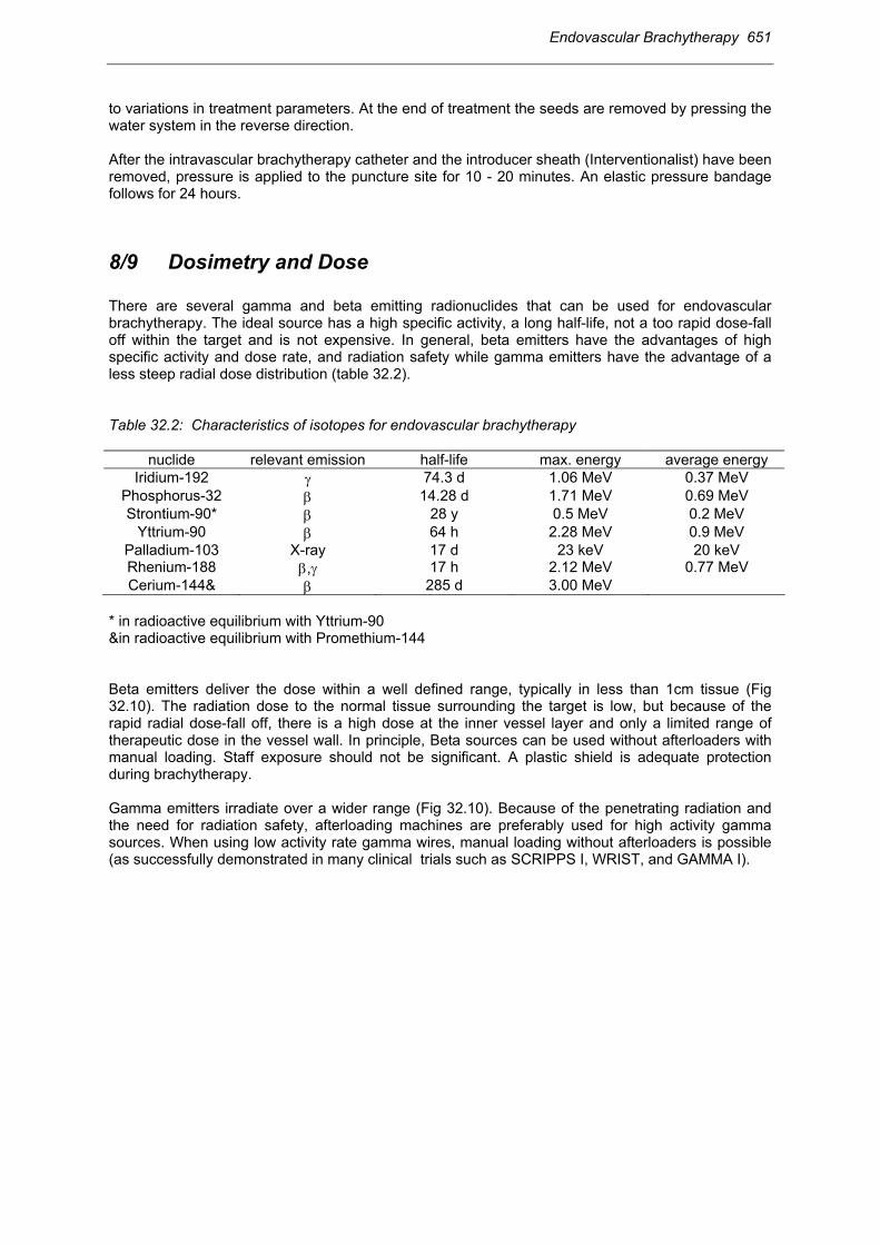
to variations in treatment parameters. At the end of treatment the seeds are removed by pressing the water system in the reverse direction. After the intravascular brachytherapy catheter and the introducer sheath (Interventionalist) have been removed, pressure is applied to the puncture site for 10 - 20 minutes. An elastic pressure bandage follows for 24 hours. 8/9 Dosimetry and Dose There are several gamma and beta emitting radionuclides that can be used for endovascular brachytherapy. The ideal source has a high specific activity, a long half-life, not a too rapid dose-fall off within the target and is not expensive. In general, beta emitters have the advantages of high specific activity and dose rate, and radiation safety while gamma emitters have the advantage of a less steep radial dose distribution (table 32.2). Table 32.2: Characteristics of isotopes for endovascular brachytherapy
nuclide relevant emission half-life max. energy average energy Iridium-192 γ 74.3 d 1.06 MeV 0.37 MeV
Phosphorus-32 β 14.28 d 1.71 MeV 0.69 MeV Strontium-90* β 28 y 0.5 MeV 0.2 MeV
Yttrium-90 β 64 h 2.28 MeV 0.9 MeV Palladium-103 X-ray 17 d 23 keV 20 keV Rhenium-188 β,γ 17 h 2.12 MeV 0.77 MeV Cerium-144& β 285 d 3.00 MeV
* in radioactive equilibrium with Yttrium-90 &in radioactive equilibrium with Promethium-144 Beta emitters deliver the dose within a well defined range, typically in less than 1cm tissue (Fig 32.10). The radiation dose to the normal tissue surrounding the target is low, but because of the rapid radial dose-fall off, there is a high dose at the inner vessel layer and only a limited range of therapeutic dose in the vessel wall. In principle, Beta sources can be used without afterloaders with manual loading. Staff exposure should not be significant. A plastic shield is adequate protection during brachytherapy. Gamma emitters irradiate over a wider range (Fig 32.10). Because of the penetrating radiation and the need for radiation safety, afterloading machines are preferably used for high activity gamma sources. When using low activity rate gamma wires, manual loading without afterloaders is possible (as successfully demonstrated in many clinical trials such as SCRIPPS I, WRIST, and GAMMA I).

652 Endovascular Brachytherapy
Fig 32.10: Radial dose profile for three different source types used in specific systems (Kirisits (2)). As the target and thus the specification of dose is within the range of a few millimetres, uncertainties in dosimetry are considerable. The dosimetry of beta sources particularly is less established and more difficult because of the rapid dose fall-off. Dosimetric measurement techniques include thin layer TLD’s, radiochromic films, plastic scintillators and gel dosimetry. Beside analytical calculation models the use of Monte Carlo simulation seems to be a useful tool for calculating dose distribution in the vicinity of endovascular brachytherapy sources. 8.1 General aspects of dosimetry in intravascular brachytherapy The total dose of endovascular brachytherapy applied within one treatment session is recommended to be between 14 and 18 (20) Gy at a specified depth in the vessel wall. No difference is recommended for the different isotopes (beta, gamma) nor for the different dose rates applied. The treatment time varies between about 30 seconds (Phosphor-32) and 30 minutes (Iridium-192), thus the dose rates are all in the high dose rate range. As there is no agreement on the target and on prescription at present, the recommended dose is prescribed in different ways. This applies both for dose prescription in the radial and longitudinal dimensions. For the radial dose distribution this variability is indicated by the different distances from the source or from the inner vessel wall/applicator surface specified in different protocols and for different treatment devices. (Table 32.3-4) First, the dose at the prescription point must be reported. Recommendations have been made regarding a reference radial dose should also be quoted in a uniform way (GEC ESTRO recommendations 2001(5)). The AAPM 60 task group in contrast recommends reporting the dose at 2 mm from the source axis, which is independent of the situation in the patient (4). The dose for reporting according to the GEC ESTRO recommendations may be identical to the dose for prescription depending on the treatment protocol. As the thickness of the

Endovascular Brachytherapy 653
vessel wall varies with the size of the artery, 1 mm depth into the vessel wall is recommended for coronary arteries and 2 mm for femoropopliteal arteries. The reference dose at the reference depth in the central plane representing the reference lumen diameter is then calculated taking the radius of the reference vessel lumen after angioplasty and adding 1 mm for coronary arteries and 2 mm for femoropopliteal arteries. In order to assess the dose fall-off in the target, the dose at the luminal surface should also be given. For a non centred device, the maximum and minimum doses for the reference depth dose and the luminal dose should be reported in addition. If IVUS is used, more points may be added to describe the dose in terms of topography and pathology (plaque) more precisely. A well reproducible structure in the vessel wall to use as a reference point is the external elastic membrane, which can be reliably shown on IVUS. IVUS facilitates reporting of dose distribution not only in the central plane, but also in other planes in the target, to give a better idea of the dose distribution of dose throughout the vessel wall. For the longitudinal dose distribution, there is again significant variability. It is therefore necessary to follow a given terminology to define the different lengths relevant for unambiguous dosimetry, as it has been recommended recently (5). The Active Source Length (ASL) is defined as the length of the radioactive source or source train or the active dwell positions of a stepping source used to achieve the prescribed dose in the PTL. For the different isotopes and devices, the ASL is always longer than the length of the Reference Isodose (“Reference Isodose Length” (RIL)), depending on the dose fall-off, the arrangement of sources, and the vessel diameter. The Reference Isodose Length indicates the segment of the vessel wall enclosed by the 90% isodose at the reference depth. In the ideal case the RIL equals the PTL. Usually, the RIL is somewhere between the ASL and the PTL, as the ASL cannot be continuously adapted to the prescribed PTL. In the available devices, different Active Source Lengths are available which must be chosen when selecting the adequate catheter, which will ensure that the RIL covers at least the PTL. Fig 32.11: Definition of the Reference Isodose Length (RIL) based on dose distribution along the axis of the source arrangement. Different isodose lines are indicated: 100%, 90%, 50%. The Reference Depth Dose is given at the Reference Depth in the Central Plane, which represents the 100% isodose. The Reference Isodose Length is the Length enclosed by the 90%-isodose (Potter, et.al. (5)). A radiation dosimetry survey must be done before and after the procedure by measuring radiation levels: in the room, at the patient, and at the removed catheter and for the water in the Novoste system (for contamination).

654 Endovascular Brachytherapy
8.2 Dosimetry of devices for intravascular brachytherapy There is no dose uniformity in brachytherapy based on one source line. However, a defined dose should be applied to specific structures in the arterial wall. This dose variation depends partly on the centring of the source within the artery, which is influenced by the type of catheter, the cylindrical symmetry of the artery itself (deformation by arteriosclerotic plaques), and the straightness of the artery. Dose variation may be reduced by a centring device. For beta emitters - because of their short therapeutic range - centring may be even more important. 8.2.1 Femoropopliteal arteries Treatment planning for a HDR afterloading device uses a treatment planning system. After determination of the CTL and PTL, the ASL for the stepping source is programmed into the planning system. To achieve a Reference Isodose Length (RIL) enclosing the PTL the ASL must be longer than the PTL. The margin distal and proximal to the PTL depends on the dwell time optimization used and can be reduced to a few millimeters. (e.g. Dwell time optimization can be performed by defining dose points at the reference depth, parallel to the source axis, at each dwell position except for the first and last). 8.2.2 Coronary arteries 8.2.2.1 The Cordis CheckmateTM Intravascular Brachytherapy System The dose rate at 2 mm from the centre of the source axis is about 70 cGy/min per/1 GBq/ seed depending on the ASL of the source ribbon. Due to the 1 mm spacing between each seed, the dose at 2 mm from the source axis varies longitudinally. The length receiving the 90% isodose at 2 mm is about 4.5 mm shorter on each side of the source ribbon, resulting in a Reference Isodose Length which is significantly smaller than the Active Source Length (9 mm, 4.5 mm each side). A good approximation for treatment planning based on the angiogram in the cath lab is to allow for a margin of one and a half seeds, each proximal and distal to the dummy ribbon, which should be added to the PTL. This margin ensures an adequate coverage of the planning target with the therapeutic dose. Fig 32.12: Fig. 12: RIL and maximum Interventional Length for a 39 mm Active Source Length in the Cordis Checkmate System with 10 seeds of each 3 mm length and 1 mm spacing between the seeds (Kirisits (2)). A safety margin of 5 mm is added on each side: PTL 30 mm. 8.2.2.2 The Guidant GalileoTM Intravascular Radiotherapy System For brachytherapy using the P - 32 source of the Galileo System the dose rate at 2 mm from the source axis is 8,6 cGy/sec (516 cGy/min) per GBq. The stepping source technology ensures that the source is positioned without gap or overlap with no significant variations along the target in 2 mm
Endovascular Brachytherapy 655
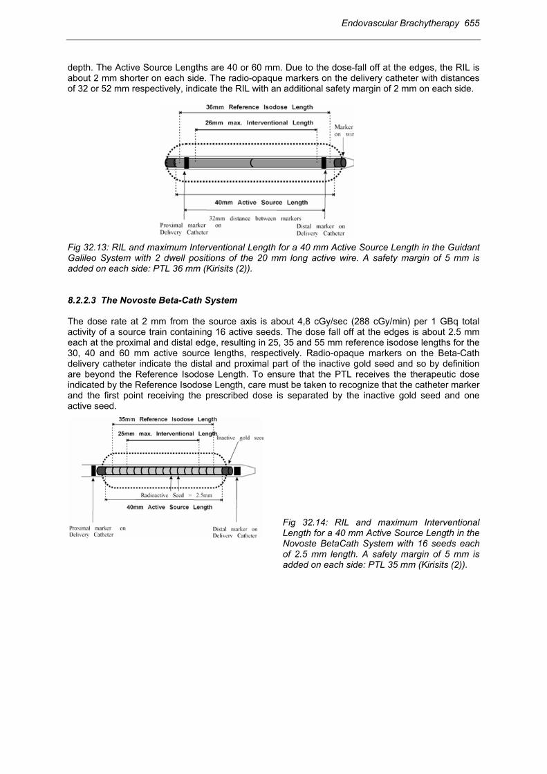
depth. The Active Source Lengths are 40 or 60 mm. Due to the dose-fall off at the edges, the RIL is about 2 mm shorter on each side. The radio-opaque markers on the delivery catheter with distances of 32 or 52 mm respectively, indicate the RIL with an additional safety margin of 2 mm on each side. Fig 32.13: RIL and maximum Interventional Length for a 40 mm Active Source Length in the Guidant Galileo System with 2 dwell positions of the 20 mm long active wire. A safety margin of 5 mm is added on each side: PTL 36 mm (Kirisits (2)). 8.2.2.3 The Novoste Beta-Cath System The dose rate at 2 mm from the source axis is about 4,8 cGy/sec (288 cGy/min) per 1 GBq total activity of a source train containing 16 active seeds. The dose fall off at the edges is about 2.5 mm each at the proximal and distal edge, resulting in 25, 35 and 55 mm reference isodose lengths for the 30, 40 and 60 mm active source lengths, respectively. Radio-opaque markers on the Beta-Cath delivery catheter indicate the distal and proximal part of the inactive gold seed and so by definition are beyond the Reference Isodose Length. To ensure that the PTL receives the therapeutic dose indicated by the Reference Isodose Length, care must be taken to recognize that the catheter marker and the first point receiving the prescribed dose is separated by the inactive gold seed and one active seed.
Fig 32.14: RIL and maximum Interventional Length for a 40 mm Active Source Length in the Novoste BetaCath System with 16 seeds each of 2.5 mm length. A safety margin of 5 mm is added on each side: PTL 35 mm (Kirisits (2)).

656 Endovascular Brachytherapy
Table 32.3 : Comparison of different doses with different systems in different trials specified according to GEC ESTRO recommendations (5) in relation to outcome: Relation between Dose and Target Lesion Revascularisation (TLR) is more pronounced for In Stent Restenosis (ISR) compared to De Novo Lesions (provided by M Martens and E Van Limbergen) .
Table 32.4 : Reference Depth dose as a function of the vessel diameter and different prescription techniques (Kirisits (2)).
10 Monitoring during vascular brachytherapy Brachytherapy prolongs the angioplasty procedure (usually by about 30 minutes), depending on different circumstances. Experience so far suggests that endovascular brachytherapy does not add significant acute risks for patients with femoropopliteral artery lesions, but in coronary arteries adds the risks well known from interventional cardiology for coronary arteries.

Endovascular Brachytherapy 657
10.1 Femoropopliteal arteries For brachytherapy in femoropopliteal arteries patients’ general health status (comorbidity) must be monitored in particular with regard to the cardiovascular system. The introducer sheath must be observed for adequate positioning and as it is a potential site of bleeding. As antithrombotic treatment patients receive 5000 IU of standard heparin before the intervention. Further continuous administration of heparin in a dosage of 1000 IU/h follows for 24 hours. Acetylsalicylic acid (100 mg/day) is given long-term and if there is a stent, clopidogrel (75 mg/ day) for at least 6 months to prevent late-stent thrombosis and occlusion. 10.2 Coronary arteries Endovascular brachytherapy in coronary arteries represents a risk which is comparable to the risks of interventional cardiology and angioplasty. As the coronary blood flow is often impaired by the intravascular brachytherapy catheter (in particular using balloons), the patients need specific monitoring during this time period. Because of increased ischemia, the patient may experience angina with corresponding changes in the ECG. Cardiac arrhythmia may also occur. If angina is significant or major irregularities on the ECG are seen the intervention procedure is temporarily interrupted. Patients receive 3000-5000 IU of standard heparin before the intervention. Further administration of heparin depends on values of activated clotting time (ACT). Additional long-term acetylsalicylic acid, oral anticoagulants and in the case of stenting clopidogrel (75mg/day for 6 -12 months) must be prescribed.
11 Results 11.1 Treatment outcome 11.1.1 Femoropopliteal arteries The first clinical trial started in 1990 (1) using HDR remote afterloading 192Ir Brachytherapy after PTA plus stent implantation for treatment of restenosis in femoro-popliteal arteries with a dose of 12 Gy at 3 mm from the source axis. Only three patients our of 30 developed restenosis after a follow-up period of 4 - 68 months. No acute or late adverse side effects were observed (8). Prospective randomised trials have been set up by different groups (Vienna, PARIS, Switzerland) using similar techniques, but only a few results are available at present. The Vienna group performed a prospective, randomized trial comparing PTA versus PTA+ BT for non-stented lesions (6). A total of 113 patients were included. A Dose of 12 Gy was prescribed at 3 mm distance from the source axis. Following EVA GEC ESTRO recommendations the dose was 6.8 Gy at 2 mm distance from the vessel lumen (vessel radius 3mm + 2 mm). The primary endpoint of the study was femoropopliteal patency after 6 months. No acute, subacute and late adverse side effects related to BT were seen after a mean follow up of 12 months (6 - 24 months). Crude restenosis rate at 6 months was 54% in the PTA arm vs. 28% in the PTA + BT arm. Actuarial estimate of the patency rate was at 6 months (PTA group) 45% vs. 72%. (PTA + BT group). The cumulative patency rates at 12 months were 64% in the PTA+BT group and 35% in the PTA group. The pilot experience from the “PARIS”-trial in 35

658 Endovascular Brachytherapy
patients showed angiographic restenosis at 6 months in 17.2% and clinical restenosis at 12 months in 13.3%. A centring balloon was used. The dose was 14 Gy at 2 mm depth in the vessel wall. If recanalisation is unsuccessful (re-stenosis >30%, multiple dissections) a stent is introduced into the femoropopliteal arteries. These procedures are associated with a significant risk of restenosis. This risk has been reduced by adding brachytherapy from the expected 70-80% to 30% in the pilot Vienna-4 study using a centring catheter with a dose of 14 Gy at 2 mm depth in the vessel wall (17).
Table 32.5 Results from femoropopliteal trials.
Study Design Stent Centering catheter Brachytherapy Dose
@ mm Patients Results
Vienna-1 Phase I no no HDR
Iridium- 192 12 Gy 3 mm 10
Restenosis rate 12 months
40 %
Vienna-2
Phase III no no HDR
Iridium- 192 12 Gy 3 mm 113
Restenosis rate 6 months PTA 54%
PTA + BT 28%
Vienna-3 Phase III no yes HDR
Iridium- 192 18 Gy
r + 2 mm 135
closed pending
Vienna-4
Phase I/II yes yes HDR
Iridium- 192 14 Gy
r + 2 mm 33 Restenosis rate
6 months 30 %
Vienna-5 Phase III yes yes HDR
Iridium- 192 14 Gy
r + 2 mm 90
recruiting pending
Tabelle 32.5A: Vienna studies on HDR brachytherapy in SFA
r = postinterventional vessel radius SFA = superficial femoropopliteal artery Study Design Stent Centering
catheter Brachytherapy Dose @ mm Patients Results
Frankfurt
Phase I/ II yes no HDR
Iridium-192 12 Gy 3 mm 28
Restenosis rate 5 years
23% PARIS- Pilot
Phase III no yes HDR Iridium-192
14 Gy r + 2 mm 35
Restenosis rate 12 months
13 %
PARIS Phase III no yes HDR Iridium-192
14 Gy r + 2 mm
300 closed pending
Bern Phase II no no HDR
Iridium-192 12 Gy 5 mm
54 recruiting
Restenosis rate 6 months PTA 35%
PTA + BT 25% Table 32.5B: Clinical studies on gamma HDR brachytherapy in SFA.
11.1.2 Coronary arteries There have been several trials of coronary brachytherapy since the mid nineties, many of them were double blind randomised prospective trials, preceded by feasibility studies and followed by registry

Endovascular Brachytherapy 659
trials. Results reported so far refer to more than 2000 patients and mainly focus on the overall therapeutic effect of vascular brachytherapy. The double blind randomised trials based on Iridium-192 brachytherapy (manual loading) have all a significant angiographic reduction in restenosis rate at 6 months follow up for lesion lengths < 50 mm. the most notable of them are the following: SCRIPPS I (single centre): restenotic native coronary arteries or saphenous venous grafts (SVG) in 55 patients from 54% to 17% (9), reduction rate of 68%; GAMMA I (multicentre): in-stent restenosis of coronary arteries in 252 patients from 56% to 34%, (3) reduction rate of 39%. WRIST (single centre): in-stent restenosis of coronary arteries and SVG in 130 patients from 58% to 19% (16), reduction rate of 67%. The clinical outcome was also significantly improved, although the difference was mostly less pronounced. Clinical outcome was measured by major adverse cardiac events (MACE), which included the need for target lesion and vessel revascularisation and myocardial infarction .
Table 32.6: Results from intracoronory trials: A. Gamma, B. Beta
Study Design Lesion Type Centering Device Dose [Gy] Patients Restenosis PTCA/PTCA+BT
SCRIPPS I single center double blind
in-stent +50% de-novo
no Ir-192 seed ribbon
8-30 to EEL IVUS based
55 3 years 48 / 15 %
GAMMA 1 muliti-center Phase III
in-stent no Ir-192 seed ribbon
8-30 to EEL IVUS based
252 6 months 56 / 34 %
WRIST single center in-stent no Ir-192 seed ribbon
15 at 2 or 2.4 mm
130 6 months 58 / 19 %
Table 32.6.A: Gamma Trials
Study Design Lesion Type Centering Device Dose [Gy] Patients Restenosis PTCA/PTCA+BT
BETA WRIST
single center non-
randomized
in-stent yes Y-90 Boston-
Scientific
20.6 at r+1 mm
50 6 months 22 %
START multi-center Phase III
in-stent no Sr-90/Y-90 Novoste
16 or 20 at 2 mm
476 6 months 45 / 29 %
Dose finding Study
multi-center Phase II
de-novo +28% stent
PTCA only
yes Y-90 Boston-
Scientific
9,12,15,18 at r+1 mm
181 6 months 29/21/16/15 %
28/17/16/4 %
INHIBIT multi-center Phase III
in-stent yes P-32 Guidant
20 at r+1 mm
332 9 months 52/26 %
BETA CATH
multi-center Phase III
de-novo PTCA only
+ stent
no Sr-90/Y-90 Novoste
16 or 20 at 2 mm
504 452
36 / 21 % 35 / 45 %
Table 32.6.B: Beta Trials For intravascular brachytherapy based on beta sources the results reported in the early experience have been less favourable. The first Geneva study proved feasiblity using the Schneider-Sauerwein-Boston Scientific System (Yttrium-90, centring balloon), but showed no apparent effectiveness in de-novo lesions (11). The multicentre Geneva dose - finding study revealed a significant reduction of

660 Endovascular Brachytherapy
restenosis rate using 9 Gy, 12 Gy, 15 Gy and 18 Gy (13). A total of 181 patients with de-novo lesions were randomly assigned to receive brachytherapy delivered by a centred yttrium-90 source. Adjunctive stenting was performed in 28% of patients. The restenosis rate was 28%, 17%, 16% and 4 %, respectively showing that with increase of dose there is a significant decrease in neointimal formation. The START trial was the first to show a significant reduction in angiographic and clinical restenosis rate based on beta radiation with the Novoste System (Strontium-90) from 45% to 29% and from 24% to 16%, respectively. This study was in coronary brachytherapy to undertake a more systematic analysis for the different lengths. Looking at the vessel segment which received the therapeutic dose, the results in this study are even more favourable (angiographic results for in-stent segment 41% in placebo vs. 14% in the BT group). In the INHIBIT trial (brachytherapy with centring catheter, Phosphorous-32 source, dose of 20 Gy at 1 mm depth in the vessel wall) restenosis rate was reduced from 52% in the placebo group to 26% in BT group. The Beta-Cath trial (90Sr) included patients with single de-novo or restenotic lesions. The restenosis rate in the primary lesion and/or the stent was significantly lower in the BT group. By expanding the analysed segment proximal and distal to the lesion length, restenosis rate increased in the BT group. The use of a new stent and additional brachytherapy gave negative results for this patient group. The results can probably be explained by the use of inadequate safety margins in the study protocol already designed in 1996. Restenosis at the stent edge represents one of the major problems at present, in particular in coronary beta brachytherapy, probably mainly due to insufficient safety margins. The radial dose distribution also represents a major problem due to the pathologic eccentricity of the vessel. This “topographic effect” is more pronounced when using beta sources. Another important issue which has recently been reported from longer follow-up of the early trials (SCIPPS 1, WRIST, VIENNA 2) is the occurrence of “late events”. These are restenoses occurring in the second and third year after brachytherapy, which reduce the therapeutic benefit, as such late events have hardly been observed in the control arms of these trials (10). Another increasingly recognized problem - based on the quantitative analysis of coronary angiography - is geographical miss, with inadequate coverage of the PTL by the therapeutic radiation dose represented by the RIL. (ESTRO Recommendations 2001 with “Interventional Length, Planning Target Length, Reference Isodose Length, Active Source Length”). The problem of geographical miss will certainly be reduced in future by using appropriate safety margins. 11.2 Adverse side effects Up till now - in more than 5000 patients enrolled into vascular brachytherapy trials - few adverse side effects have been reported. These findings contrast with what would be expected from long term experience with occlusive vessel disease in conventional radiotherapy after high radiation doses, especially in small vessels < 100 µm. This paradox is poorly explained by classical radiobiology background. However, it must be admitted, that the follow up of the majority of patients treated with endovascular brachytherapy is rather short, and only a small number of patients has had systematic follow up including e.g. angiography and IVUS for many years. But even in such patients long term adverse side effects have hardly been reported (8,10). Late Stent Thrombosis has recently been reported as a sudden thrombotic occlusion of the stent taking place at about 4 - 6 months after brachytherapy. This Late Stent Thrombosis is seen in patients in whom a fresh stent was used at the time of brachytherapy, with a frequency going up to 15%. It is hardly ever seen, if a stent is not used. The underlying mechanism of action seems to be the inhibition of endothelial re-growth to cover the stent struts. In the coronary arteries late stent thrombosis may lead to acute ischemia and infarction. In the femoropopliteal arteries the clinical consequences are less dramatic. If antiplatelet treatment is given for at least 6 months (e.g. clopidrogel), this serious side effect seems to be minimised.

Endovascular Brachytherapy 661
Aneurysm formation has been associated with early coronary brachytherapy experience. It is not yet clear whether there is a definite correlation. If many patients with a benign disease are going to be treated with brachytherapy, the issue of induction of malignancy must be carefully considered and long term follow-up is needed. ----------------------------- Brachytherapy to prevent from restenosis after angioplasty has proved to be feasible and effective but it is still at an early stage. There are many issues to be resolved such as definition of the target volume, optimal dose and dose distribution and the most effective delivery method. Carefully designed and performed follow-up studies are needed for many years to determine the long term therapeutic benefit and adverse side effects of brachytherapy.
12 References 1. Böttcher HD, Schopohl B, Liermann D, et al. Endovascular irradiation-a new method to avoid
recurrent stenosis after stent implantation in peripheral arteries: technique and preliminary results. Int J Radiat Oncol Biol Phys 1994; 29: 183-6.
2. Kirisits C. Physical aspects of endovascular brachytherapy. Doctoral thesis, Technical University Vienna 2001.
3. Leon MB, Teirstein PS, Moses JW, et al. Localized intracoronary gamma-radiation therapy to inhibit the recurrence of restenosis after stenting. N Engl J Med 2001; 344 (4): 250-6.
4. Nath R, Anderson L, Luxton G, et al. Dosimetry of interstitial brachytherapy sources, recommendations of the AAPM Radiation Therapy Committee Task Group No.43. Med Phys 1995; 22 (2): 209-34.
5. Pötter R, Van Limbergen E, Dries W, et al. GEC ESTRO Recommendations for prescribing, recording, and reporting endovascular brachytherapy. Radiother Oncol 2001; 59: 339-60.
6. Pokrajac B, Pötter R, Maca T, et al. Intra-arterial 192Ir HDR brachytherapy for prophylaxis of restenosis after femoropopliteal percutaneous transluminal angioplasty: the prospective randomized Vienna-2 trial. Radiotherapy parameters and risk factors analysis. Int J Radiat Oncol Biol Phys 2000; 48 (4): 923-31.
7. Popowski Y, Verin V, Urban P. Endovascular ß-irradiation after percutaneous transluminal coronary balloon angioplasty. Int J Radiat Oncol Biol Phys 1996; 36: 841-45.
8. Schopohl B, Lierman D, Jülling-Pohlit L, et al. 192Ir endovascular brachytherapy for avoidance of intimal hyperplasia after percutaneous transluminal angioplasty and stent implantation in peripheral vessels. 6 years of experience. Int J Radiat Oncol Biol Phys 1996; 36: 835-40.
9. Teirstein PS, Massullo V, Jani S, et al. Catheter-based radiotherapy to inhibit restenosis after coronary stenting. N Engl J Med 1997; 336: 1697-703.
10. Teirstein PS, Massullo V, Jani S, et al. Three-year clinical and angiographic follow-up after intracoronary radiation: results of a randomized clinical trial. Circulation 2000; 101 (4) : 360-65.
11. Verin V, Urban P, Popowski Y, et al. Feasibility of intracoronary ß-irradiation to reduce restenosis after balloon angioplasty. A clinical pilot study. Circulation 1997; 95: 1138-44.
12. Verin V, Popowski Y, Urban P, et al. Intra-arterial beta irradiation prevents neointimal hyperplasia in a hypercholesterolemic rabbit restenosis model. Circulation 1995; 92: 2284-90.
13. Verin V, Popowski Y, de Bruyne B, et al. Endoluminal beta-Radiation Therapy for the Prevention of Coronary Restenosis after Balloon Angioplasty. N Engl J Med 2001; 344 (4): 243-49.
14. Waksman R, Robinson KA, Crocker IR, et al. Endovascular low-dose irradiation inhibits neointima formation after coronary artery balloon injury in swine. A possible role for radiation therapy in restenosis prevention. Circulation 1995; 91: 1533-39.
15. Waksman R (ed): Vascular Brachytherapy (2nd edition) 1999; Futura Publishing, New York.

662 Endovascular Brachytherapy
16. Waksman R., White RL, Chan RC, et al. Intracoronary ß-Radiation Therapy after angioplasty inhibits recurrence in patients with in-stent restenosis. Circulation 2000; 101: 2165-71.
17. Wolfram R., Pokrajac B, Ahmadi R, et al. Endovascular brachytherapy for prophylaxis against restenosis after long- segment femoropopliteal stenting: Initial results. Radiology 2001; 220: 724-29.
Acknowledgements: We are grateful for advice and support to Boris Pokrajac and Christian Kirisits from Vienna University department of radiotherapy.