Embed Size (px)
DESCRIPTION
Citation preview
1. External Components XCITING 400i
1-1
External Components
This chapter covers the location and servicing of the external components for the
KYMCO XCITING 400i.
• Exhaust System 2-11
• Seat 12-13
• Luggage Box 14-16
• Rear Carrier 17-18
• Center Cover 19-20
• Side Covers 21-22
• Body Cover 23-32
• Front Cover 33-45
• Front Cover Meter 46-49
• Inner Cover 50-57
• Front Fender 58-60
• Rear Fender 61-66
• Handlebar Cover 67-71
• Under Cover 72-73
1. External components > Exhaust System XCITING 400i
1‐2
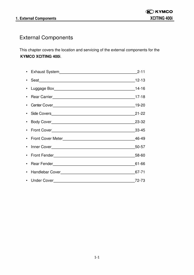
Exhaust System
SAFETY FIRST: Protective gloves and eyewear are recommended at this point.
General Instructions
• When removing frame covers, use care not to pull them by force because the cover joint
claws may be damaged.
• Make sure to route cables and harnesses according to the Cable & Harness Routing.
Troubleshooting
Noisy exhaust muffler • Damaged exhaust muffler • Exhaust muffler joint air leaks
Lack of power • Caved exhaust muffler • Clogged exhaust muffler • Exhaust muffler air leaks
Removal
1. External components > Exhaust System XCITING 400i
1‐3
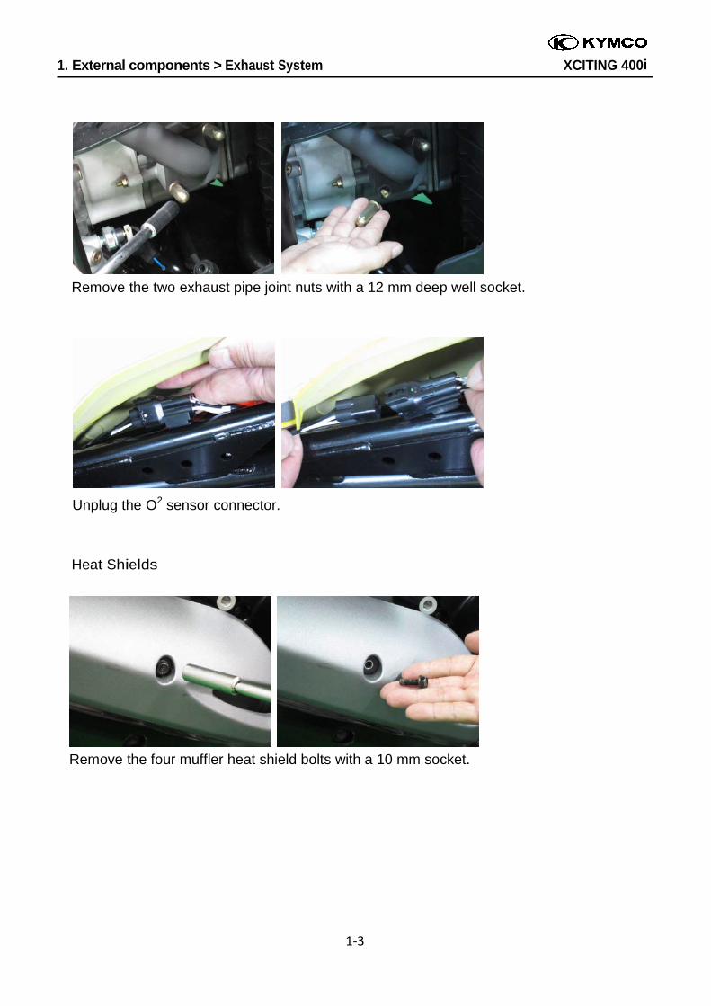
Remove the two exhaust pipe joint nuts with a 12 mm deep well socket.
Unplug the O2 sensor connector.
Heat Shields
Remove the four muffler heat shield bolts with a 10 mm socket.
1. External components > Exhaust System XCITING 400i
1‐4
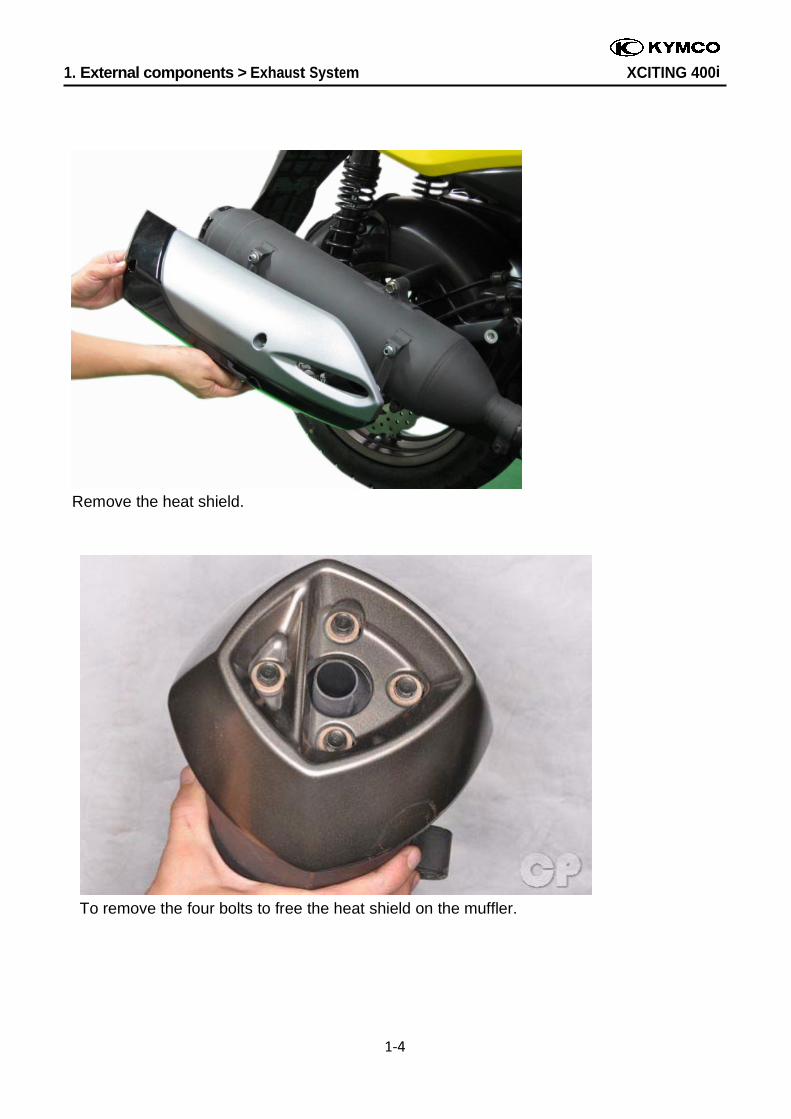
Remove the heat shield.
To remove the four bolts to free the heat shield on the muffler.
1. External components > Exhaust System XCITING 400i
1‐5
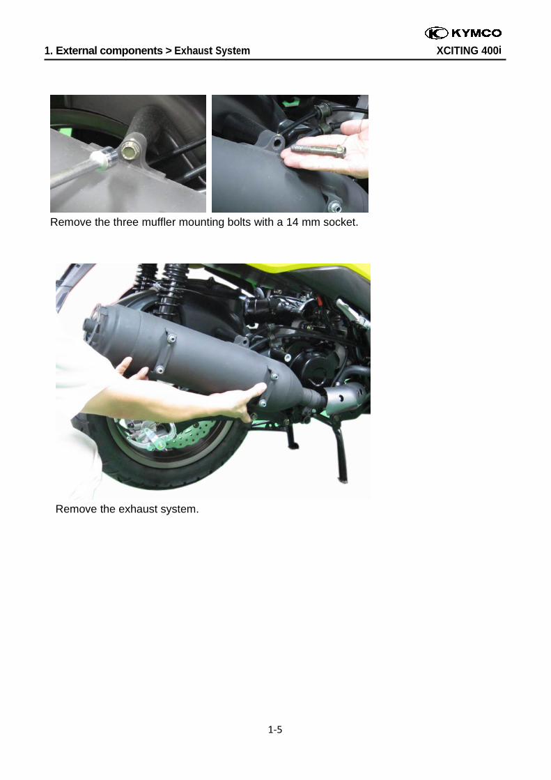
Remove the three muffler mounting bolts with a 14 mm socket.
Remove the exhaust system.
1. External components > Exhaust System XCITING 400i
1‐6
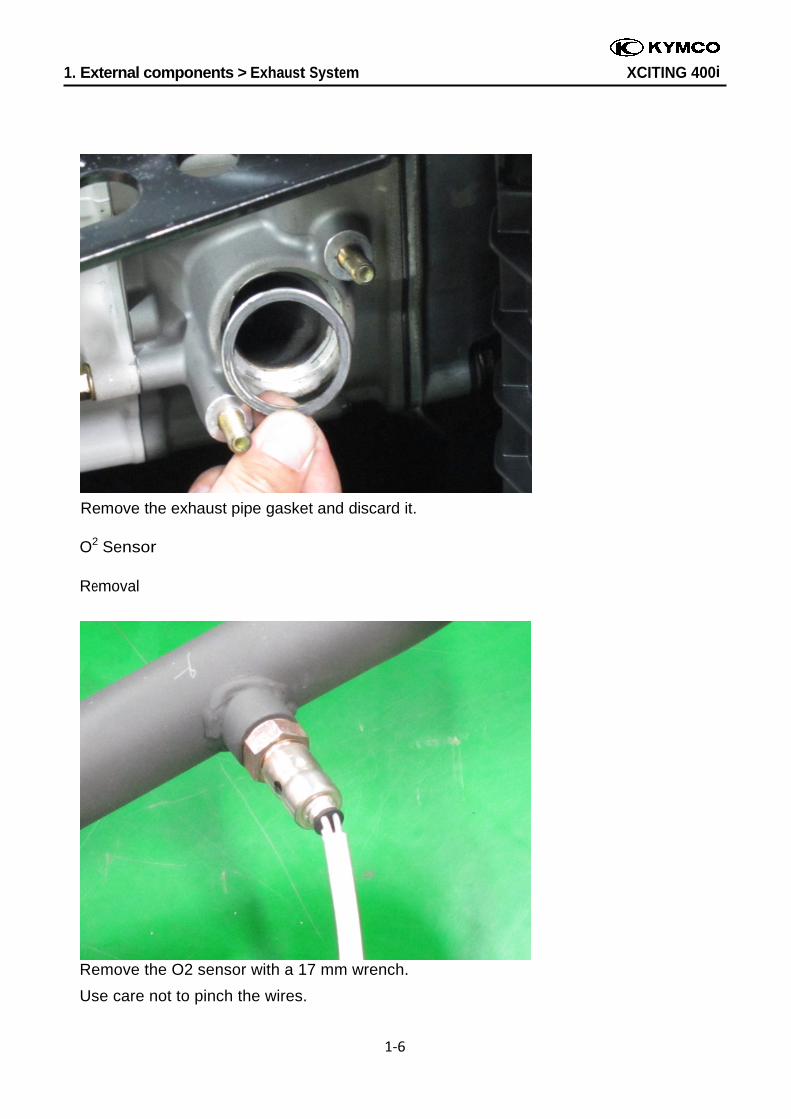
Remove the exhaust pipe gasket and discard it. O2 Sensor
Removal
Remove the O2 sensor with a 17 mm wrench.
Use care not to pinch the wires.
1. External components > Exhaust System XCITING 400i
1‐7
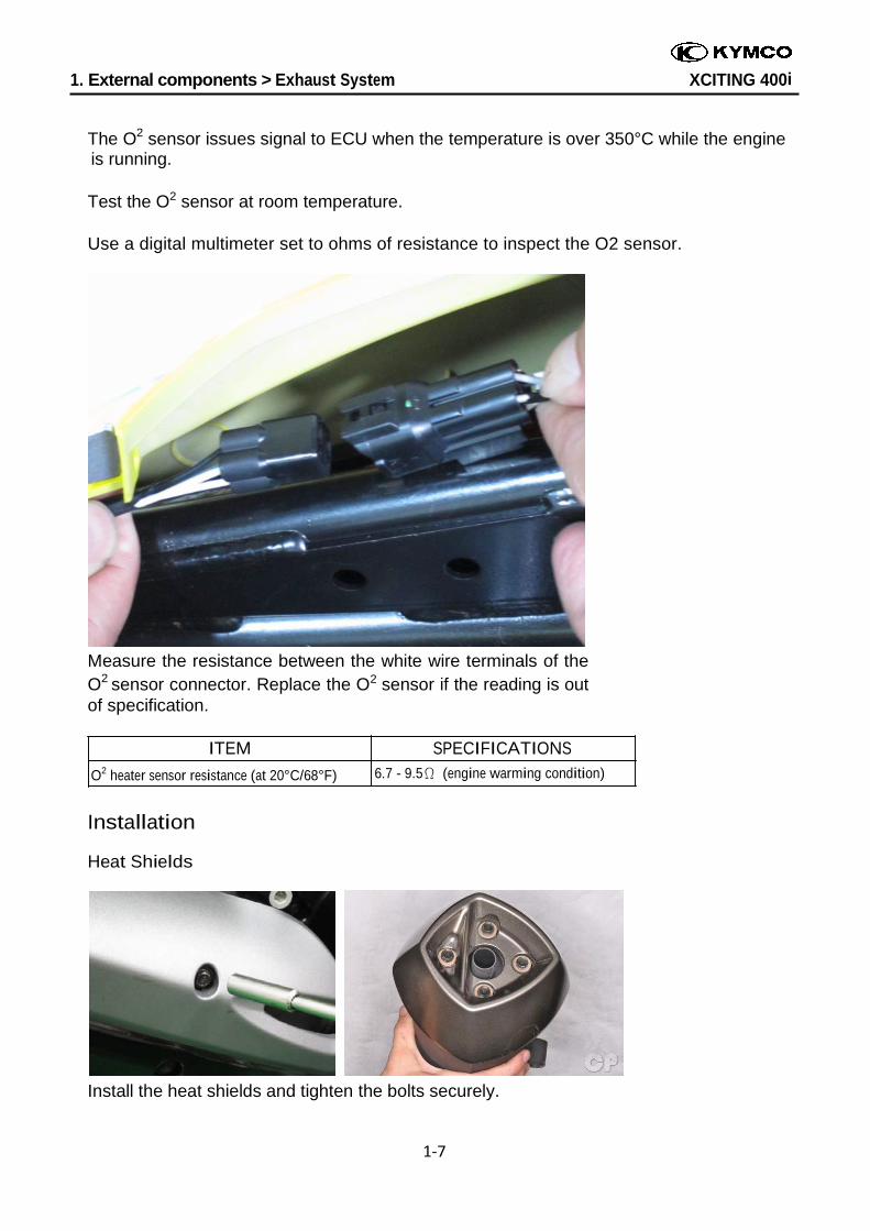
The O2 sensor issues signal to ECU when the temperature is over 350°C while the engine is running.
Test the O2 sensor at room temperature.
Use a digital multimeter set to ohms of resistance to inspect the O2 sensor.
Measure the resistance between the white wire terminals of the O2 sensor connector. Replace the O2 sensor if the reading is out of specification.
ITEM SPECIFICATIONS
O2 heater sensor resistance (at 20°C/68°F) 6.7 - 9.5Ω (engine warming condition)
Installation
Heat Shields
Install the heat shields and tighten the bolts securely.
1. External components > Exhaust System XCITING 400i
1‐8
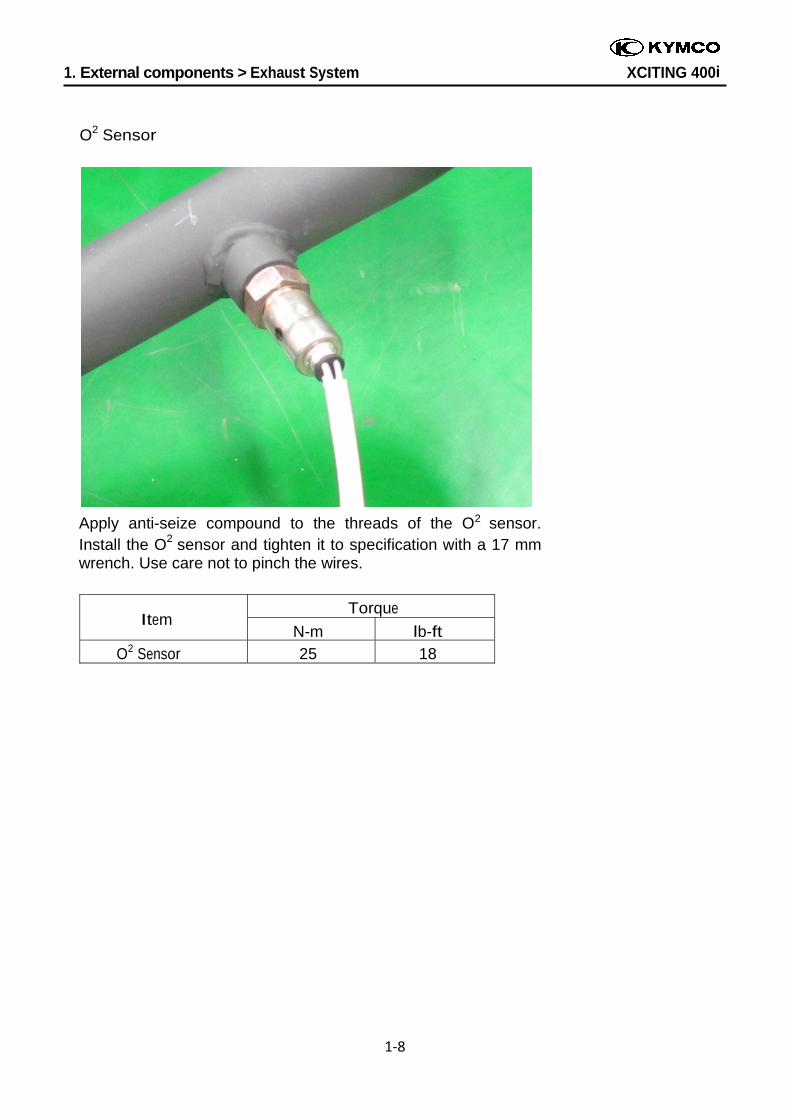
O2 Sensor
Apply anti-seize compound to the threads of the O2 sensor. Install the O2 sensor and tighten it to specification with a 17 mm wrench. Use care not to pinch the wires.
Item Torque
N-m lb-ft
O2 Sensor 25 18
1. External components > Exhaust System XCITING 400i
1‐9
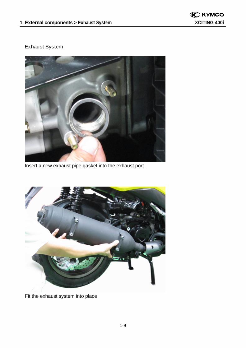
Exhaust System
Insert a new exhaust pipe gasket into the exhaust port.
Fit the exhaust system into place
1. External components > Exhaust System XCITING 400i
1‐10
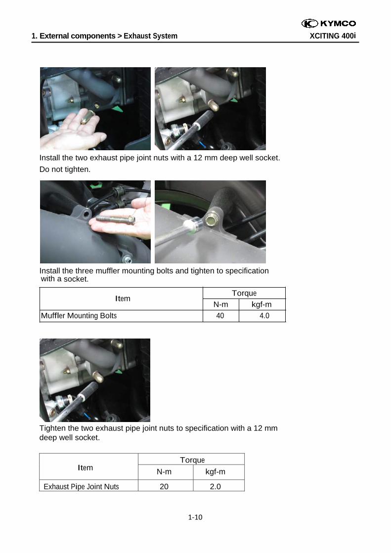
Install the two exhaust pipe joint nuts with a 12 mm deep well socket.
Do not tighten.
Install the three muffler mounting bolts and tighten to specification with a socket.
Item Torque
N-m kgf-m
Muffler Mounting Bolts 40 4.0
Tighten the two exhaust pipe joint nuts to specification with a 12 mm deep well socket.
Item Torque
N-m kgf-m
Exhaust Pipe Joint Nuts 20 2.0
1. External components > Exhaust System XCITING 400i
1‐11
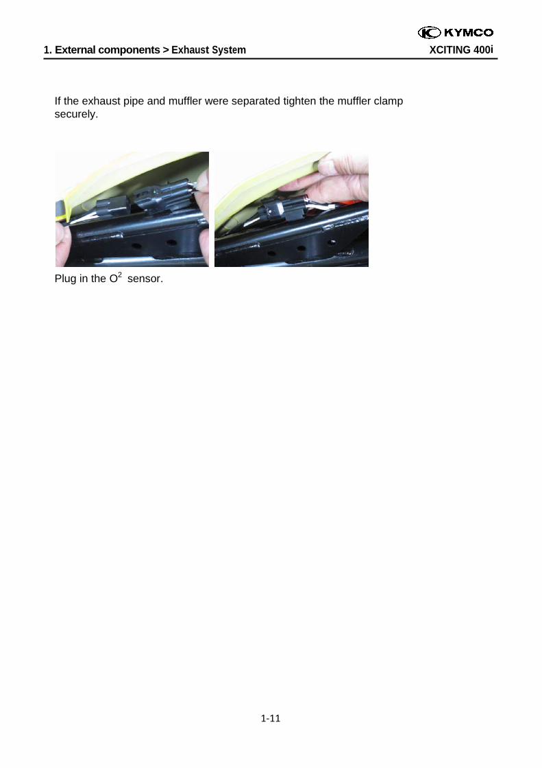
If the exhaust pipe and muffler were separated tighten the muffler clamp securely.
Plug in the O2 sensor.
1. External Components > Seat XCITING 400i
1-12
Seat
SAFETY FIRST: Protective gloves and eyewear are recommended at this point.
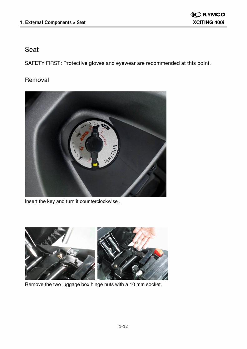
Removal
Insert the key and turn it counterclockwise .
Remove the two luggage box hinge nuts with a 10 mm socket.
1. External Components > Seat XCITING 400i
1-13
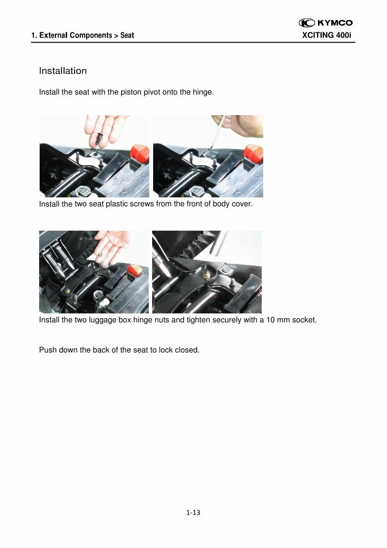
Installation
Install the seat with the piston pivot onto the hinge.
Install the two seat plastic screws from the front of body cover.
Install the two luggage box hinge nuts and tighten securely with a 10 mm socket.
Push down the back of the seat to lock closed.
1. External Components > Luggage Box XCITING 400i
1-14
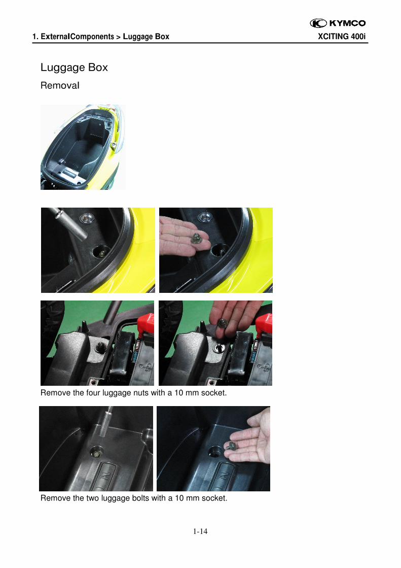
Luggage Box
Removal
Remove the four luggage nuts with a 10 mm socket.
Remove the two luggage bolts with a 10 mm socket.
1. External Components > Luggage Box XCITING 400i
1-15
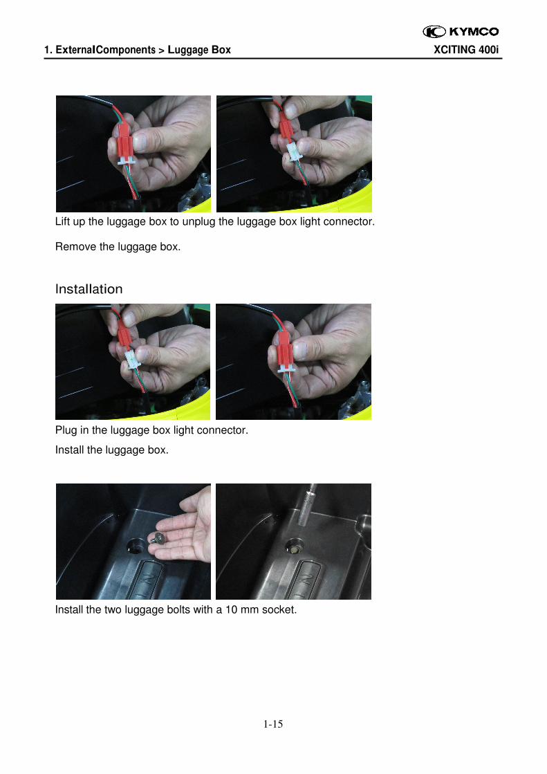
Lift up the luggage box to unplug the luggage box light connector.
Remove the luggage box.
Installation
Plug in the luggage box light connector.
Install the luggage box.
Install the two luggage bolts with a 10 mm socket.
1. External Components > Luggage Box XCITING 400i
1-16
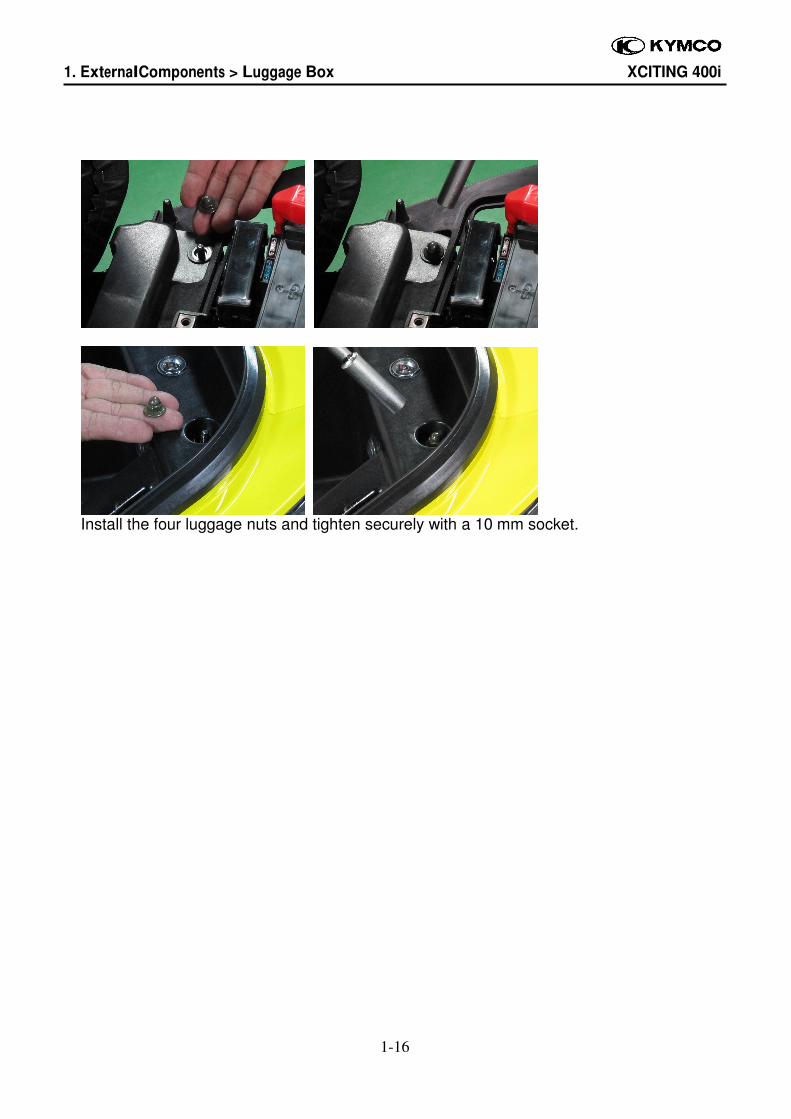
Install the four luggage nuts and tighten securely with a 10 mm socket.
1. External Components > Rear Carrier XCITING 400i
1-17
Rear Carrier
Removal
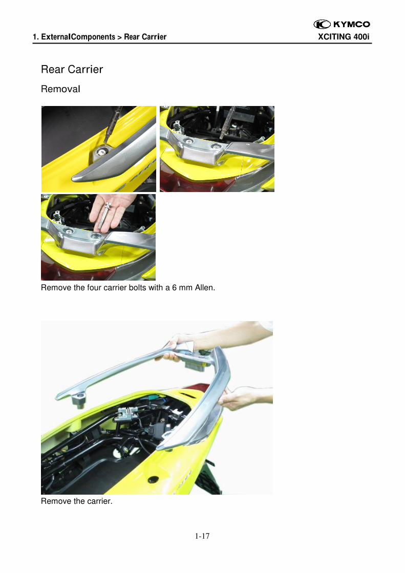
Remove the four carrier bolts with a 6 mm Allen.
Remove the carrier.
1. External Components > Rear Carrier XCITING 400i
1-18
Installation
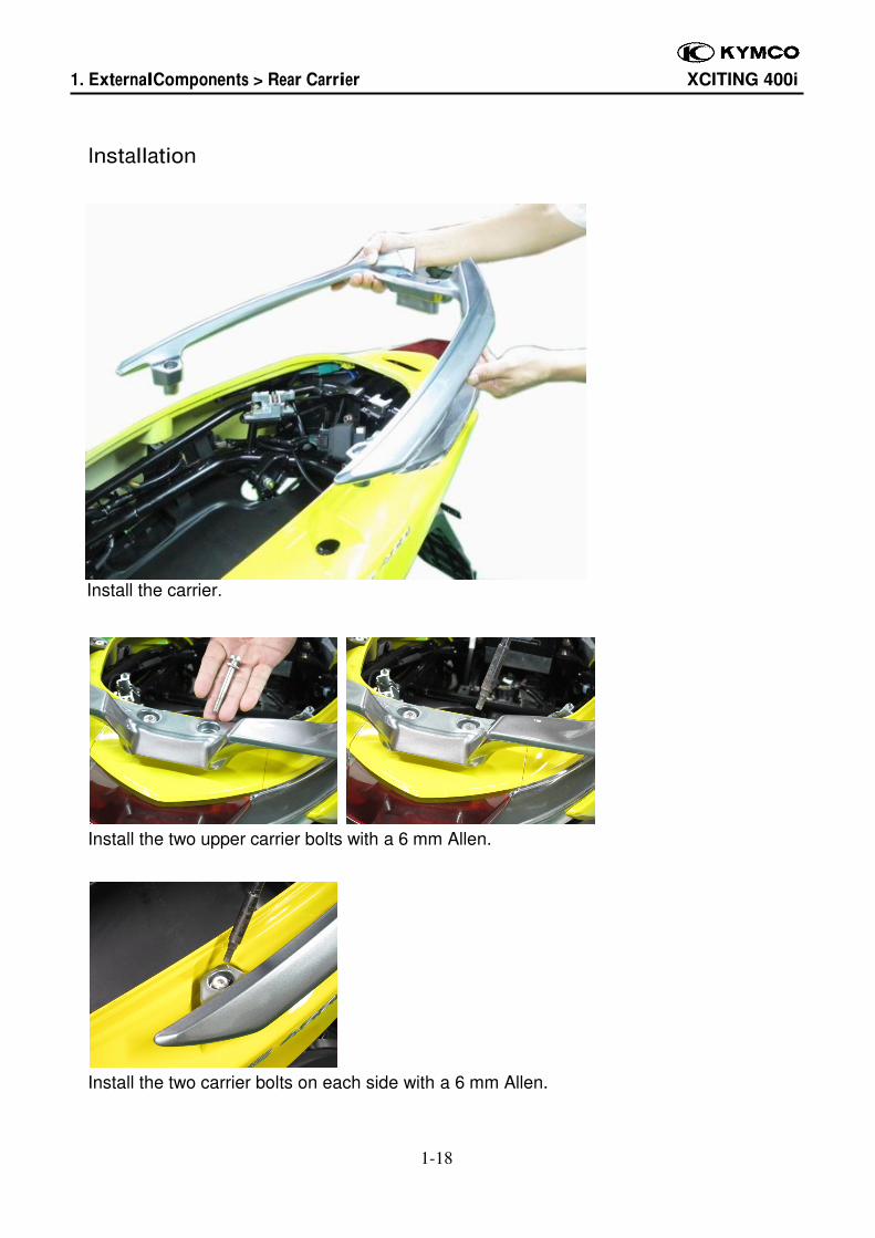
Install the carrier.
Install the two upper carrier bolts with a 6 mm Allen.
Install the two carrier bolts on each side with a 6 mm Allen.
1. External Components > Center Cover XCITING 400i
1-19
Center Cover
Removal
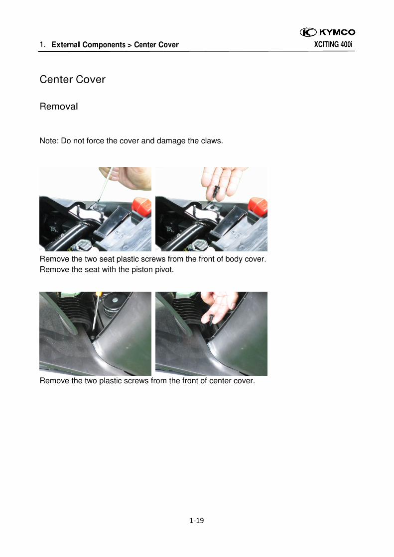
Note: Do not force the cover and damage the claws.
Remove the two seat plastic screws from the front of body cover.
Remove the seat with the piston pivot.
Remove the two plastic screws from the front of center cover.
1. External Components > Center Cover XCITING 400i
1-20
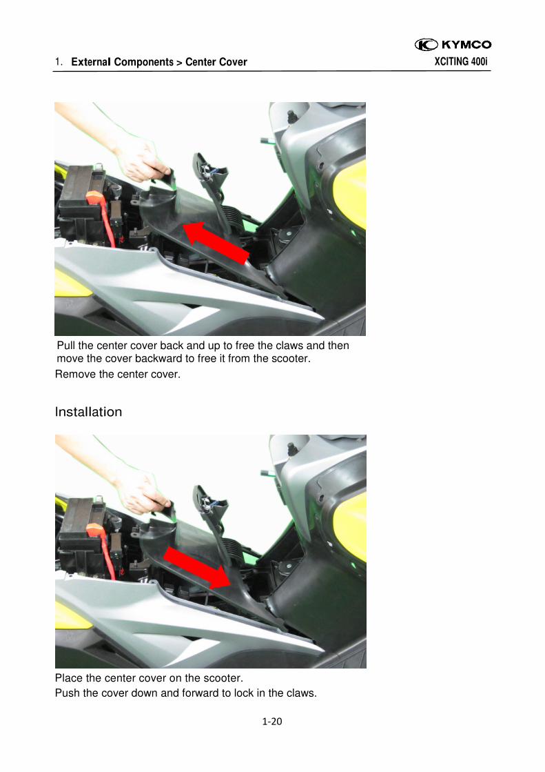
Pull the center cover back and up to free the claws and then move the cover backward to free it from the scooter.
Remove the center cover.
Installation
Place the center cover on the scooter.
Push the cover down and forward to lock in the claws.
1. External Components > Side Covers XCITING 400i
1-21
Side Covers
Removal
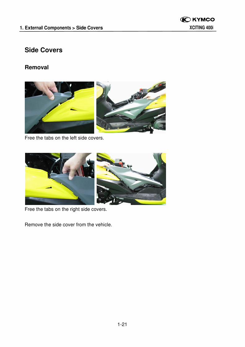
Free the tabs on the left side covers.
Free the tabs on the right side covers.
Remove the side cover from the vehicle.
1. External Components > Side Covers XCITING 400i
1-22
Installation
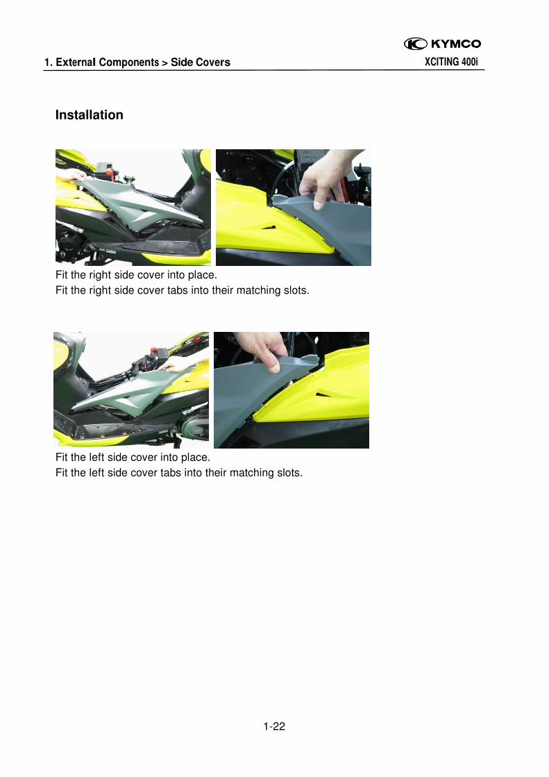
Fit the right side cover into place.
Fit the right side cover tabs into their matching slots.
Fit the left side cover into place.
Fit the left side cover tabs into their matching slots.
1. External Components > Body Cover XCITING 400i
1-23
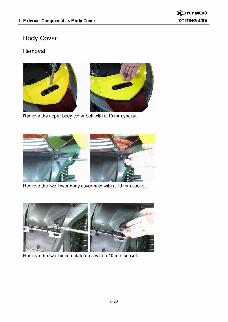
Body Cover
Removal
Remove the upper body cover bolt with a 10 mm socket.
Remove the two lower body cover nuts with a 10 mm socket.
Remove the two license plate nuts with a 10 mm socket.
1. External Components > Body Cover XCITING 400i
1-24
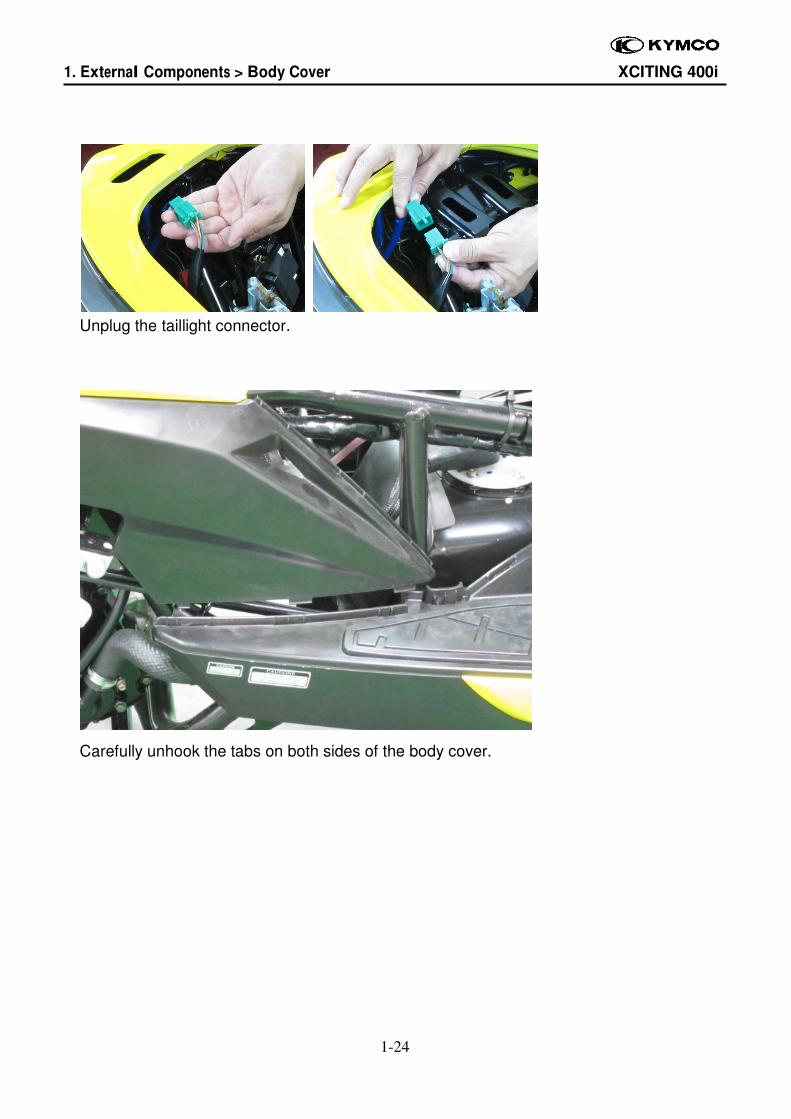
Unplug the taillight connector.
Carefully unhook the tabs on both sides of the body cover.
1. External Components > Body Cover XCITING 400i
1-25
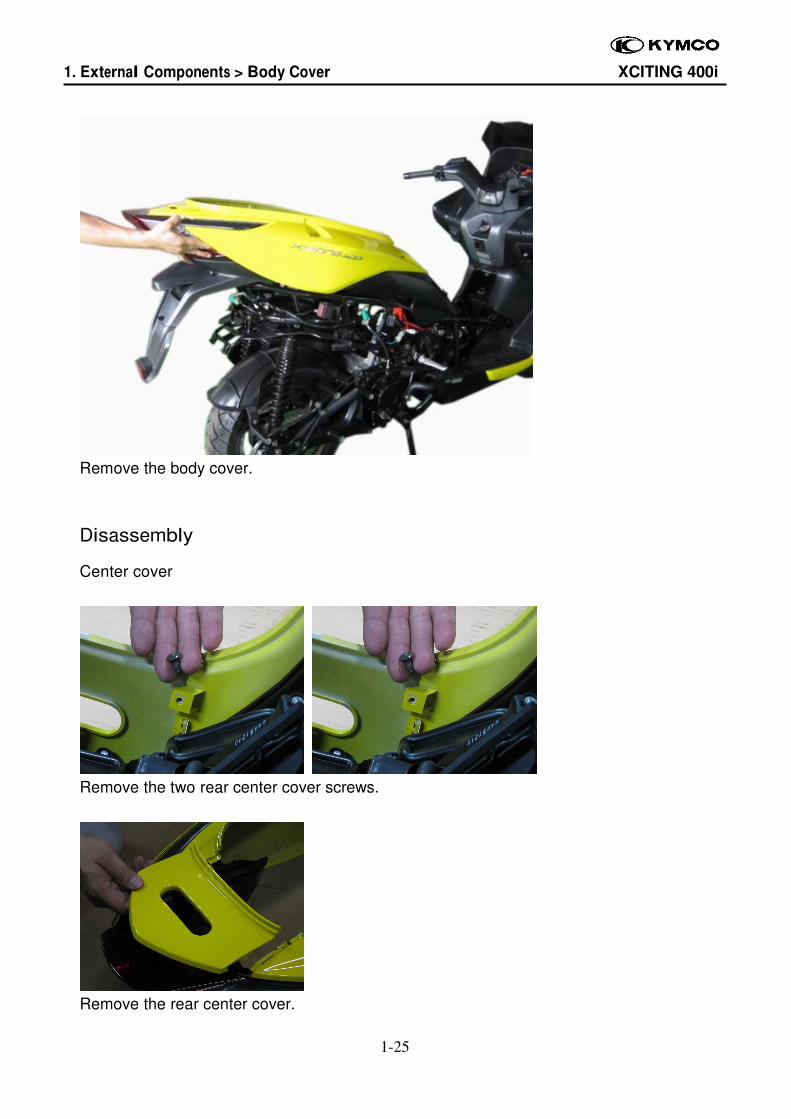
Remove the body cover.
Disassembly
Center cover
Remove the two rear center cover screws.
Remove the rear center cover.
1. External Components > Body Cover XCITING 400i
1-26
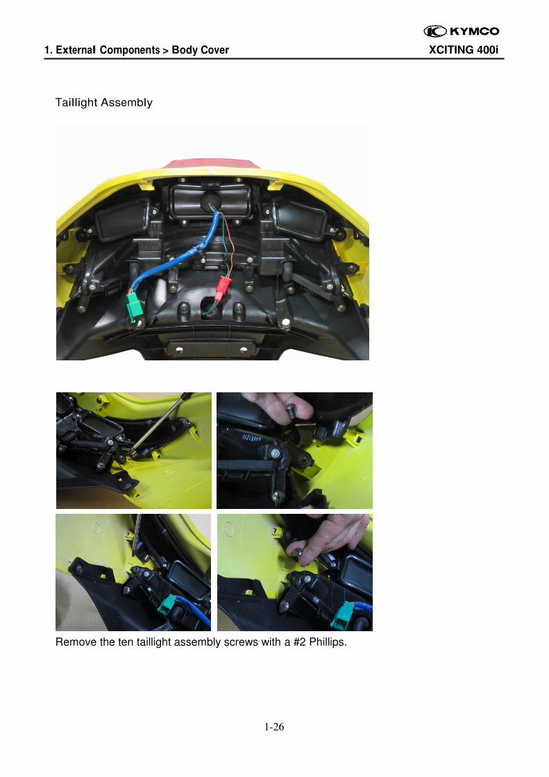
Taillight Assembly
Remove the ten taillight assembly screws with a #2 Phillips.
1. External Components > Body Cover XCITING 400i
1-27
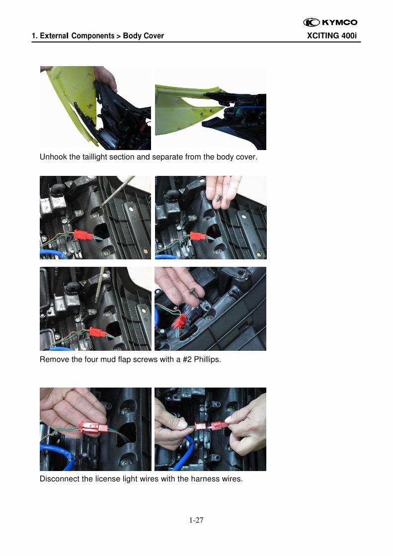
Unhook the taillight section and separate from the body cover.
Remove the four mud flap screws with a #2 Phillips.
Disconnect the license light wires with the harness wires.
1. External Components > Body Cover XCITING 400i
1-28
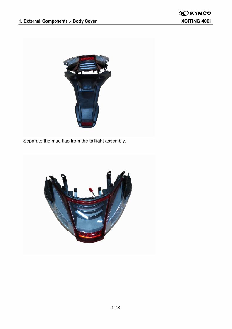
Separate the mud flap from the taillight assembly.
1. External Components > Body Cover XCITING 400i
1-29
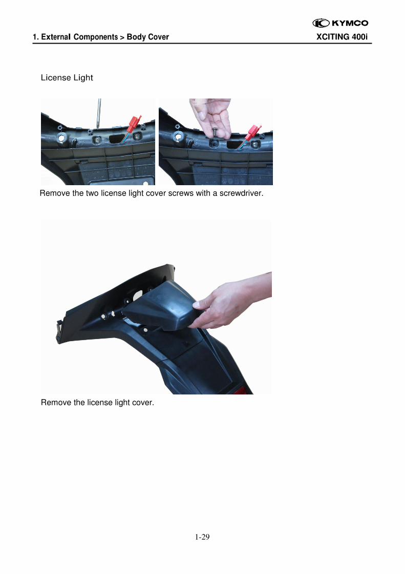
License Light
Remove the two license light cover screws with a screwdriver.
Remove the license light cover.
1. External Components > Body Cover XCITING 400i
1-30
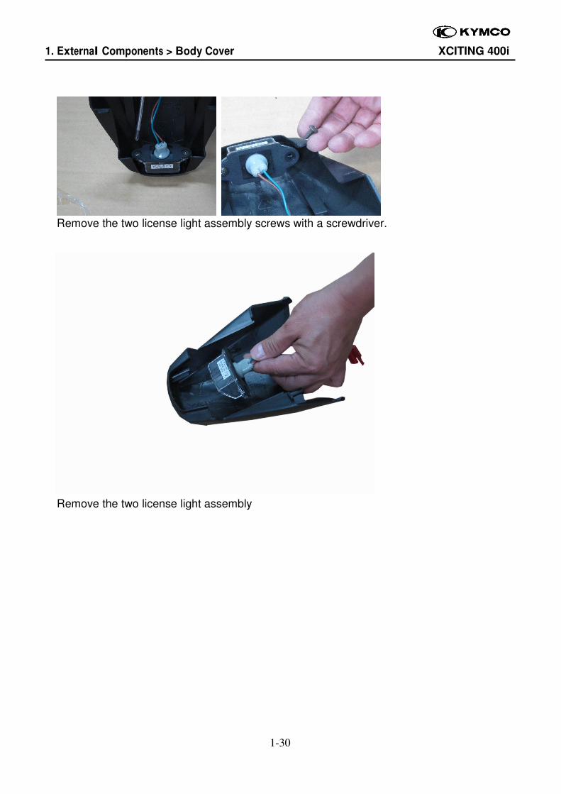
Remove the two license light assembly screws with a screwdriver.
Remove the two license light assembly
1. External Components > Body Cover XCITING 400i
1-31
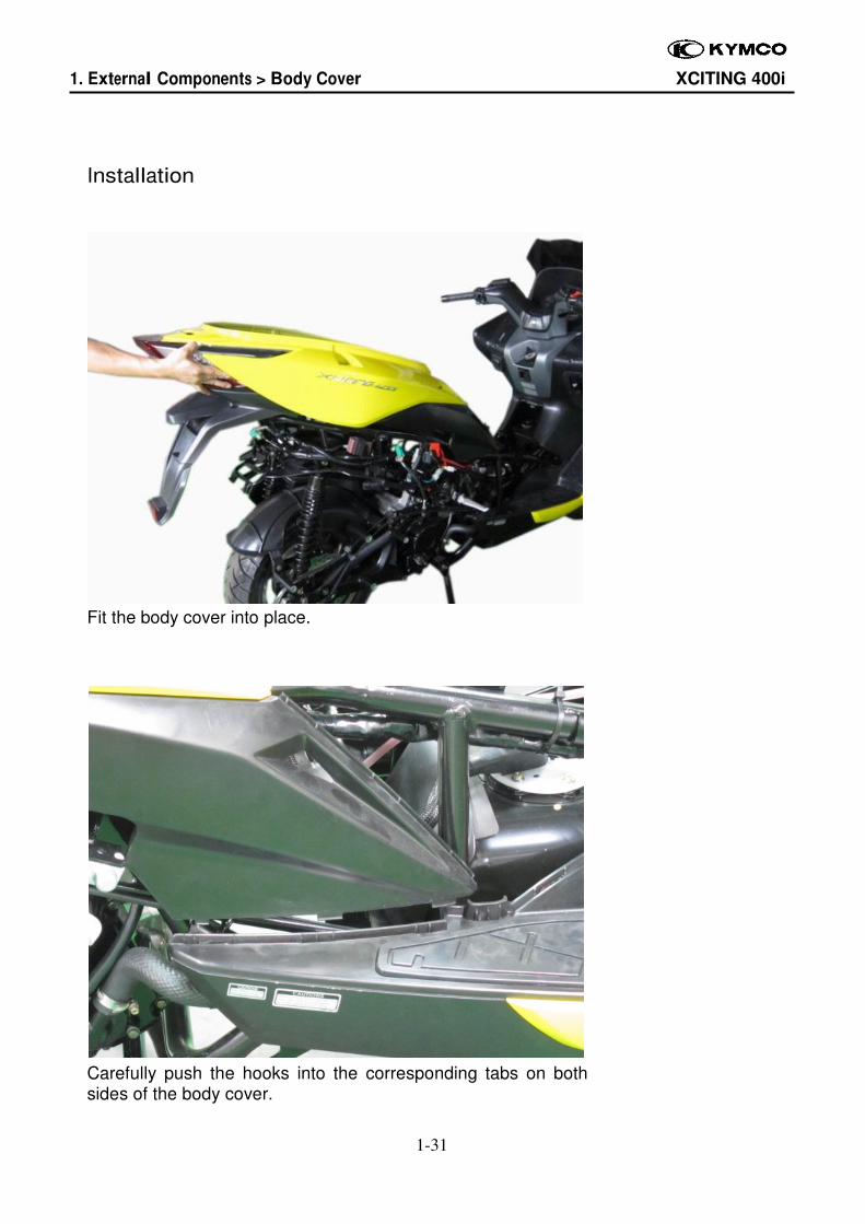
Installation
Fit the body cover into place.
Carefully push the hooks into the corresponding tabs on both sides of the body cover.
1. External Components > Body Cover XCITING 400i
1-32
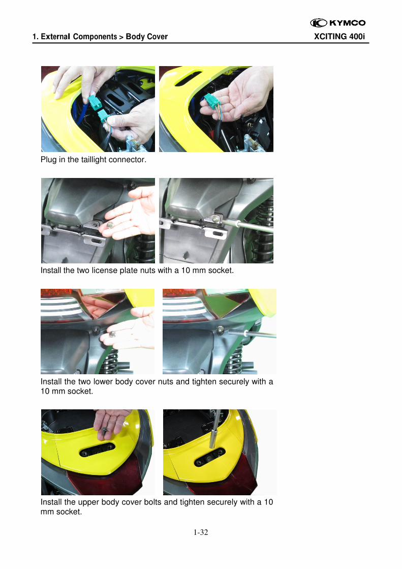
Plug in the taillight connector.
Install the two license plate nuts with a 10 mm socket.
Install the two lower body cover nuts and tighten securely with a 10 mm socket.
Install the upper body cover bolts and tighten securely with a 10 mm socket.

1. External Components > Front Cover XCITING 400i
1-33
Windshield
Removal
Remove four windshield cover bolts on both sides with a 10mm socket.
1. External Components > Front Cover XCITING 400i
1-34
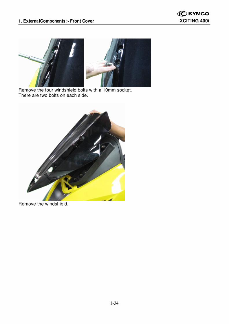
Remove the four windshield bolts with a 10mm socket. There are two bolts on each side.
Remove the windshield.
1. External Components > Front Cover XCITING 400i
1-35
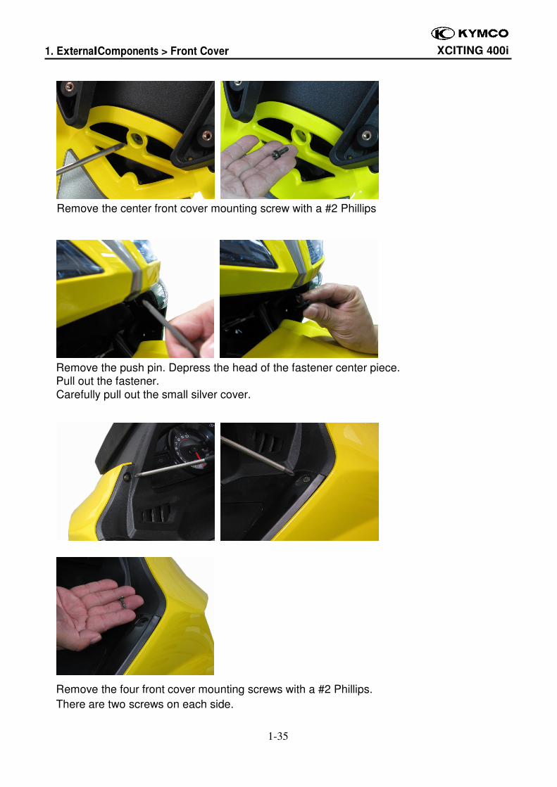
Remove the center front cover mounting screw with a #2 Phillips
Remove the push pin. Depress the head of the fastener center piece. Pull out the fastener.
Carefully pull out the small silver cover.
Remove the four front cover mounting screws with a #2 Phillips.
There are two screws on each side.
1. External Components > Front Cover XCITING 400i
1-36
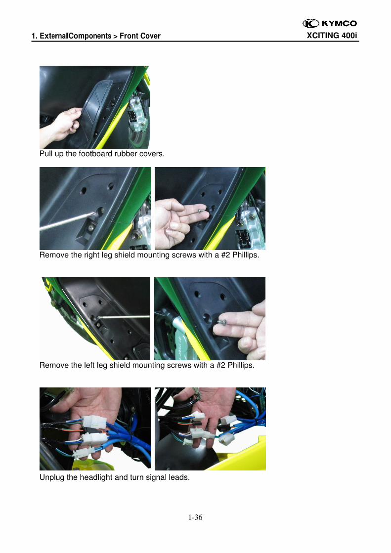
Pull up the footboard rubber covers.
Remove the right leg shield mounting screws with a #2 Phillips.
Remove the left leg shield mounting screws with a #2 Phillips.
Unplug the headlight and turn signal leads.
1. External Components > Front Cover XCITING 400i
1-37
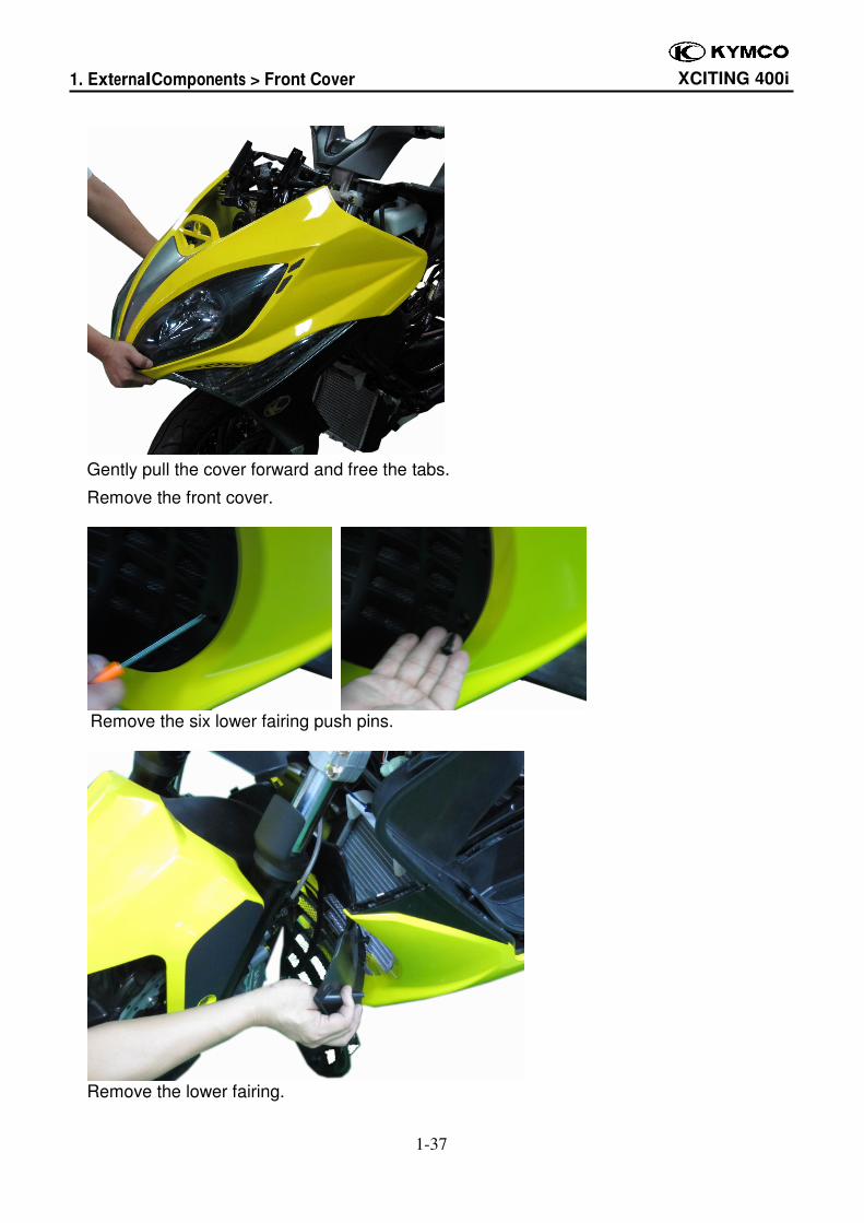
Gently pull the cover forward and free the tabs.
Remove the front cover.
Remove the six lower fairing push pins.
Remove the lower fairing.
1. External Components > Front Cover XCITING 400i
1-38
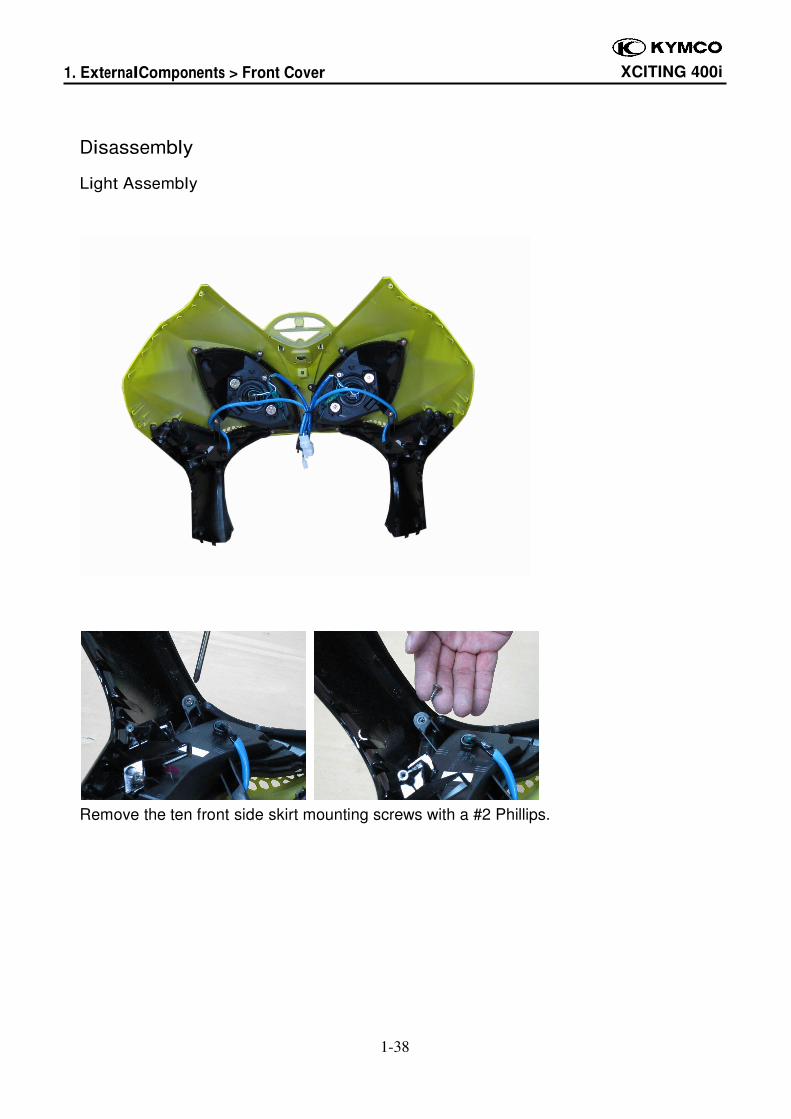
Disassembly
Light Assembly
Remove the ten front side skirt mounting screws with a #2 Phillips.
1. External Components > Front Cover XCITING 400i
1-39
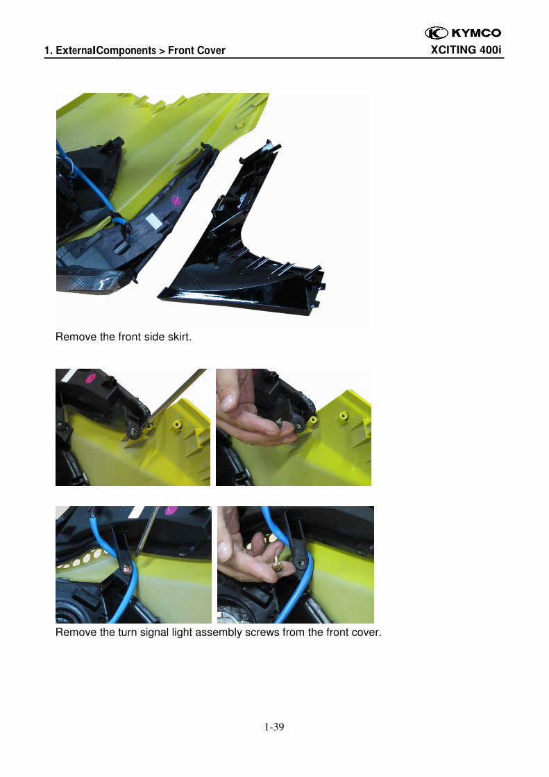
Remove the front side skirt.
Remove the turn signal light assembly screws from the front cover.
1. External Components > Front Cover XCITING 400i
1-40
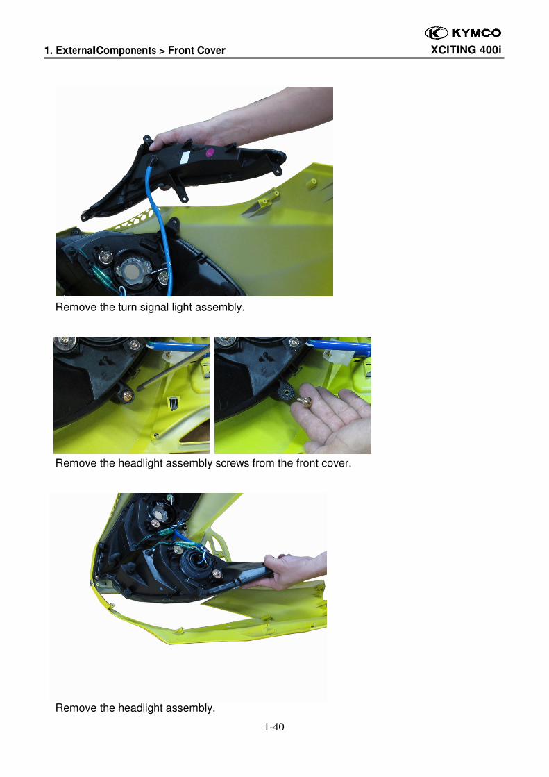
Remove the turn signal light assembly.
Remove the headlight assembly screws from the front cover.
Remove the headlight assembly.
1. External Components > Front Cover XCITING 400i
1-41
Assembly
Light Assembly
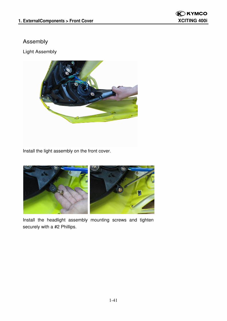
Install the light assembly on the front cover.
Install the headlight assembly mounting screws and tighten
securely with a #2 Phillips.
1. External Components > Front Cover XCITING 400i
1-42
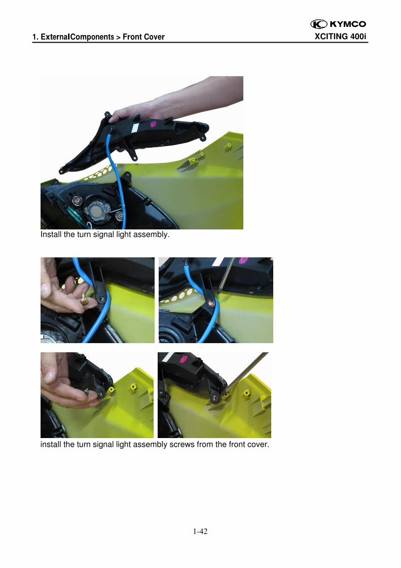
Install the turn signal light assembly.
install the turn signal light assembly screws from the front cover.
1. External Components > Front Cover XCITING 400i
1-43
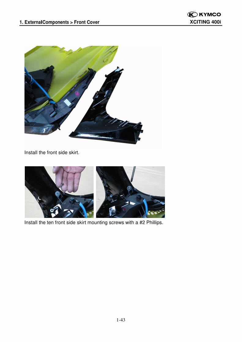
Install the front side skirt.
Install the ten front side skirt mounting screws with a #2 Phillips.
1. External Components > Front Cover XCITING 400i
1-44
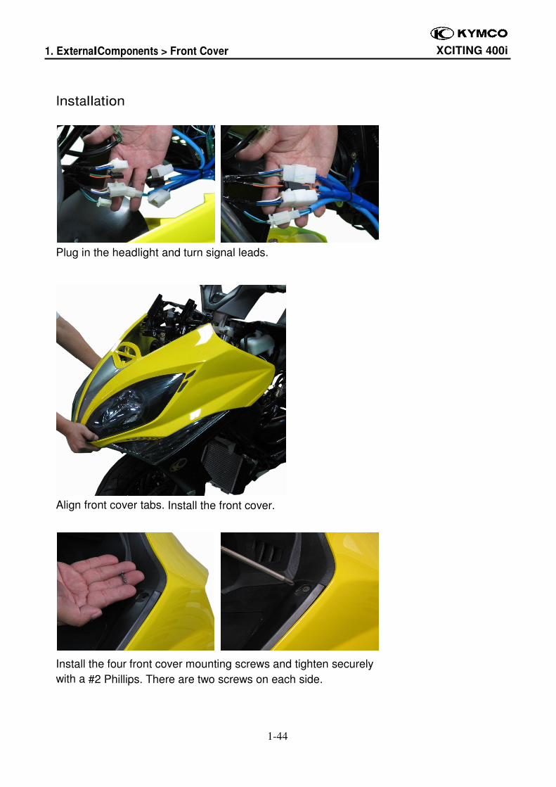
Installation
Plug in the headlight and turn signal leads.
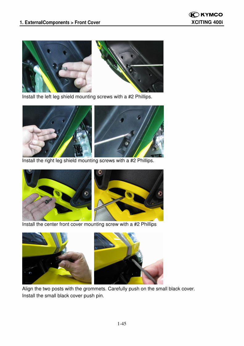
Align front cover tabs. Install the front cover.
Install the four front cover mounting screws and tighten securely
with a #2 Phillips. There are two screws on each side.
1. External Components > Front Cover XCITING 400i
1-45
Install the left leg shield mounting screws with a #2 Phillips.
Install the right leg shield mounting screws with a #2 Phillips.
Install the center front cover mounting screw with a #2 Phillips
Align the two posts with the grommets. Carefully push on the small black cover.
Install the small black cover push pin.
1. External Components > Front Cover Meter XCITING 400i
1-46
Front Cover Meter
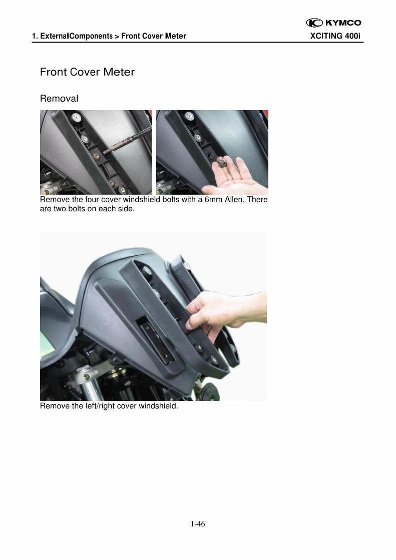
Removal
Remove the four cover windshield bolts with a 6mm Allen. There are two bolts on each side.
Remove the left/right cover windshield.
1. External Components > Front Cover Meter XCITING 400i
1-47
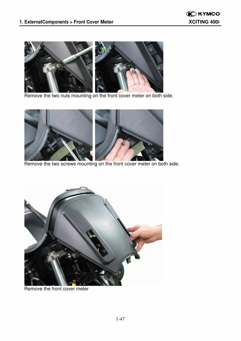
Remove the two nuts mounting on the front cover meter on both side.
Remove the two screws mounting on the front cover meter on both side.
Remove the front cover meter
1. External Components > Front Cover Meter XCITING 400i
1-48
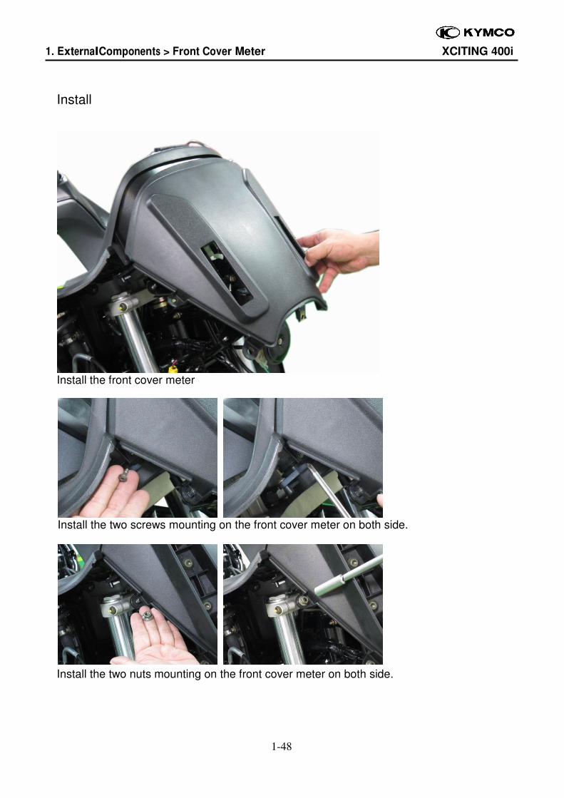
Install
Install the front cover meter
Install the two screws mounting on the front cover meter on both side.
Install the two nuts mounting on the front cover meter on both side.
1. External Components > Front Cover Meter XCITING 400i
1-49
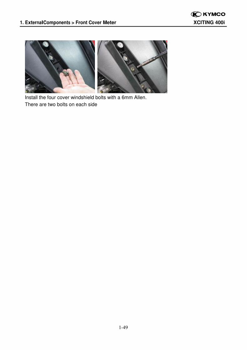
Install the four cover windshield bolts with a 6mm Allen.
There are two bolts on each side
1. External Components > Inner Cover XCITING 400i
1-50
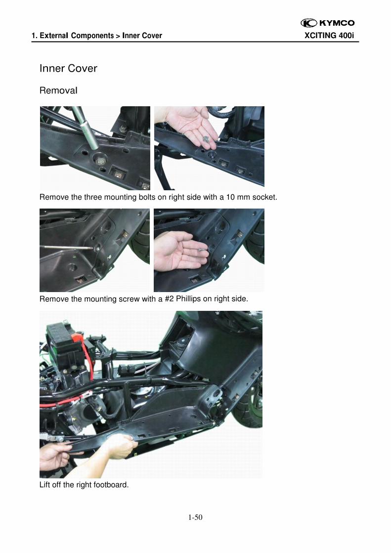
Inner Cover
Removal
Remove the three mounting bolts on right side with a 10 mm socket.
Remove the mounting screw with a #2 Phillips on right side.
Lift off the right footboard.
1. External Components > Inner Cover XCITING 400i
1-51
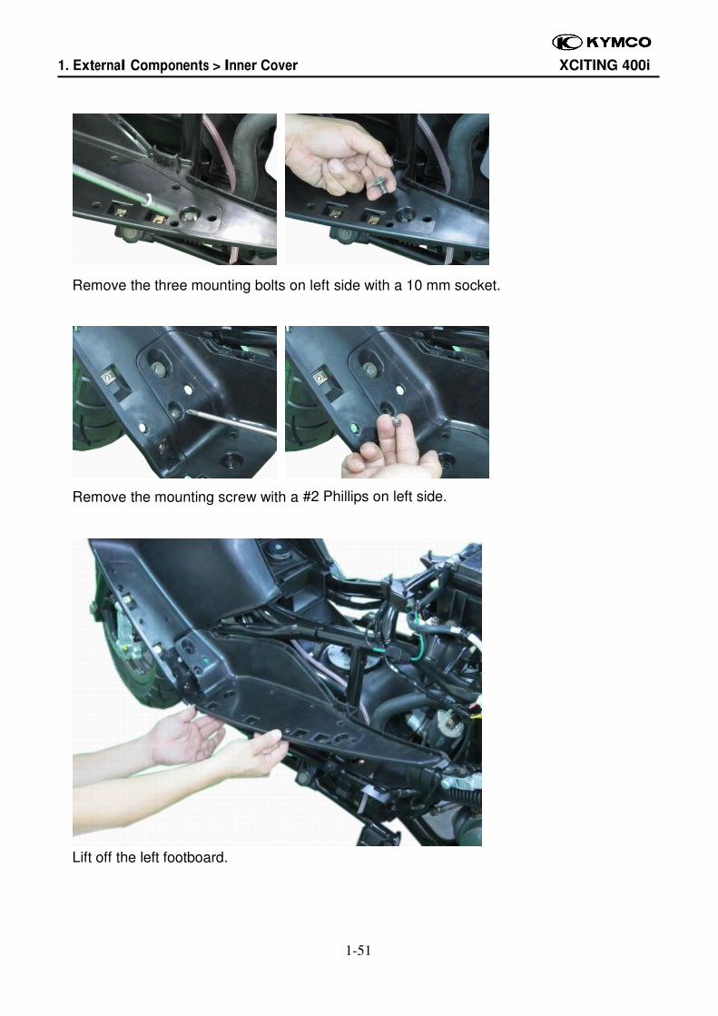
Remove the three mounting bolts on left side with a 10 mm socket.
Remove the mounting screw with a #2 Phillips on left side.
Lift off the left footboard.
1. External Components > Inner Cover XCITING 400i
1-52
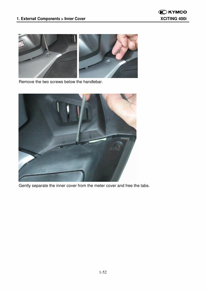
Remove the two screws below the handlebar.
Gently separate the inner cover from the meter cover and free the tabs.
1. External Components > Inner Cover XCITING 400i
1-53
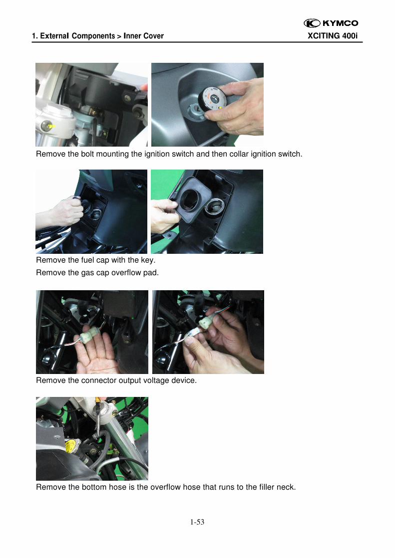
Remove the bolt mounting the ignition switch and then collar ignition switch.
Remove the fuel cap with the key.
Remove the gas cap overflow pad.
Remove the connector output voltage device.
Remove the bottom hose is the overflow hose that runs to the filler neck.
1. External Components > Inner Cover XCITING 400i
1-54
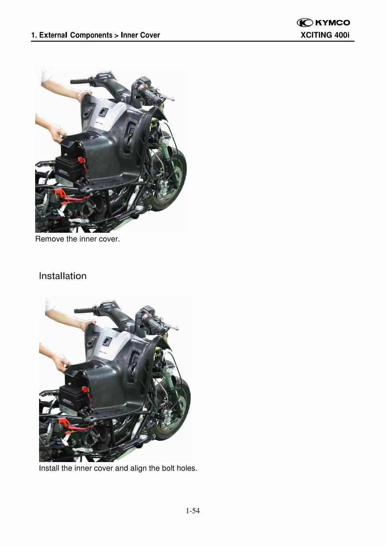
Remove the inner cover.
Installation
Install the inner cover and align the bolt holes.
1. External Components > Inner Cover XCITING 400i
1-55
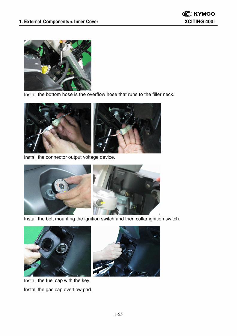
Install the bottom hose is the overflow hose that runs to the filler neck.
Install the connector output voltage device.
Install the bolt mounting the ignition switch and then collar ignition switch.
Install the fuel cap with the key.
Install the gas cap overflow pad.
1. External Components > Inner Cover XCITING 400i
1-56
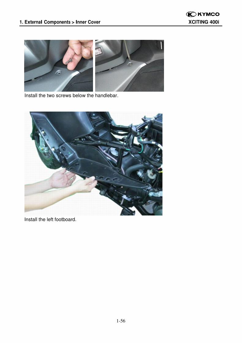
Install the two screws below the handlebar.
Install the left footboard.
1. External Components > Inner Cover XCITING 400i
1-57
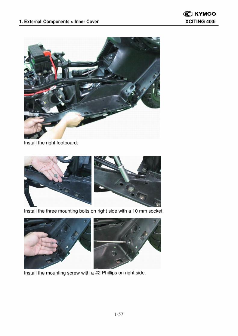
Install the right footboard.
Install the three mounting bolts on right side with a 10 mm socket.
Install the mounting screw with a #2 Phillips on right side.
1. External Components > Front Fender XCITING 400i
1-58
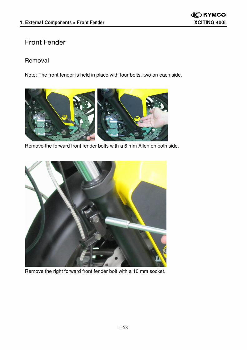
Front Fender
Removal
Note: The front fender is held in place with four bolts, two on each side.
Remove the forward front fender bolts with a 6 mm Allen on both side.
Remove the right forward front fender bolt with a 10 mm socket.
1. External Components > Front Fender XCITING 400i
1-59
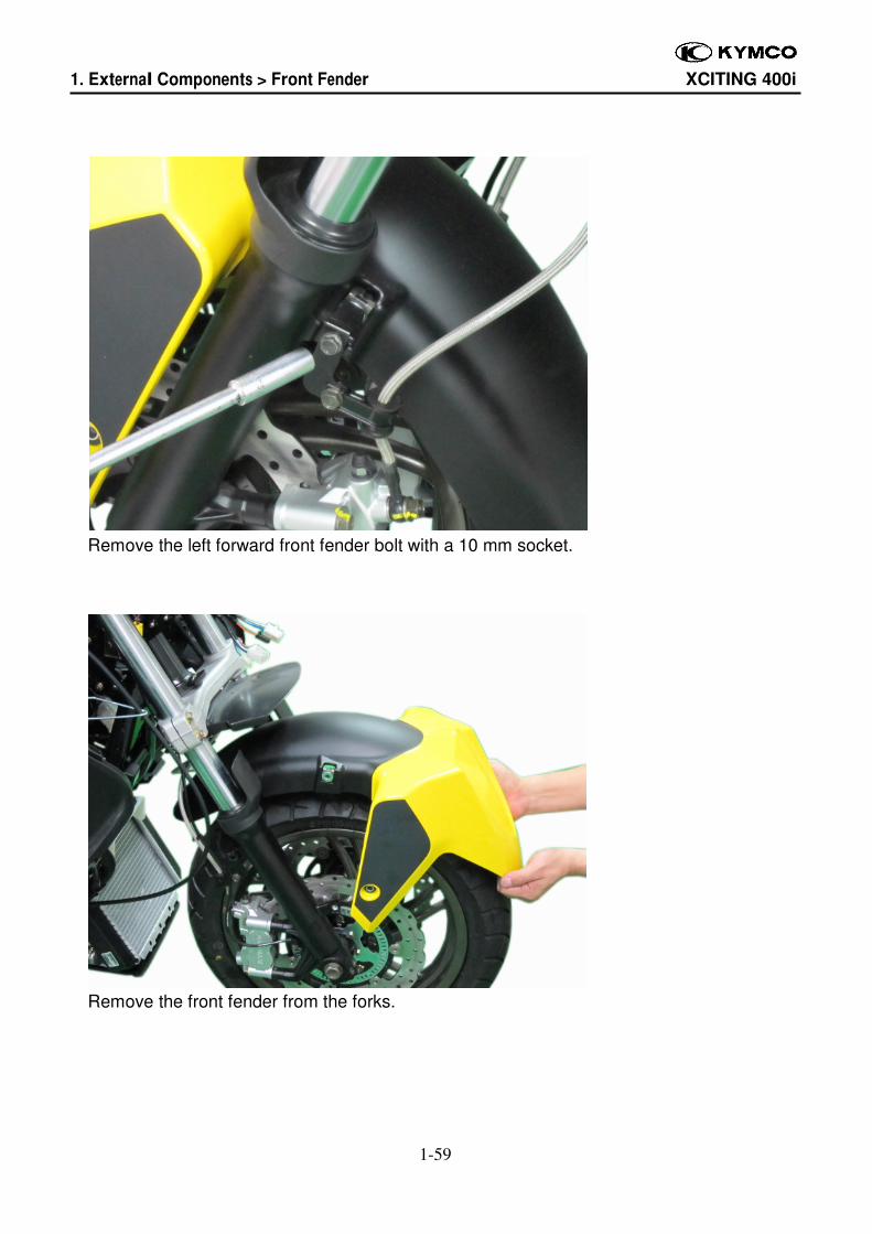
Remove the left forward front fender bolt with a 10 mm socket.
Remove the front fender from the forks.
1. External Components > Front Fender XCITING 400i
1-60
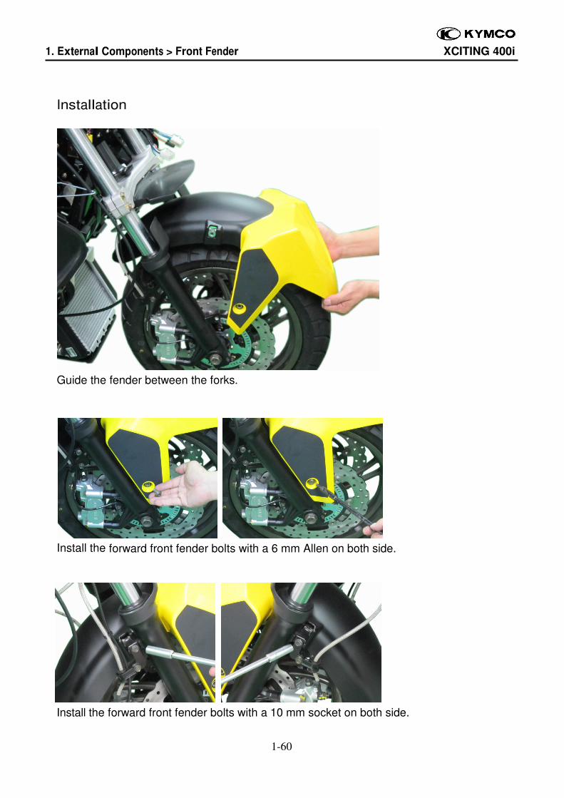
Installation
Guide the fender between the forks.
Install the forward front fender bolts with a 6 mm Allen on both side.
Install the forward front fender bolts with a 10 mm socket on both side.
1. External Components > Rear Fender XCITING 400i
1-61
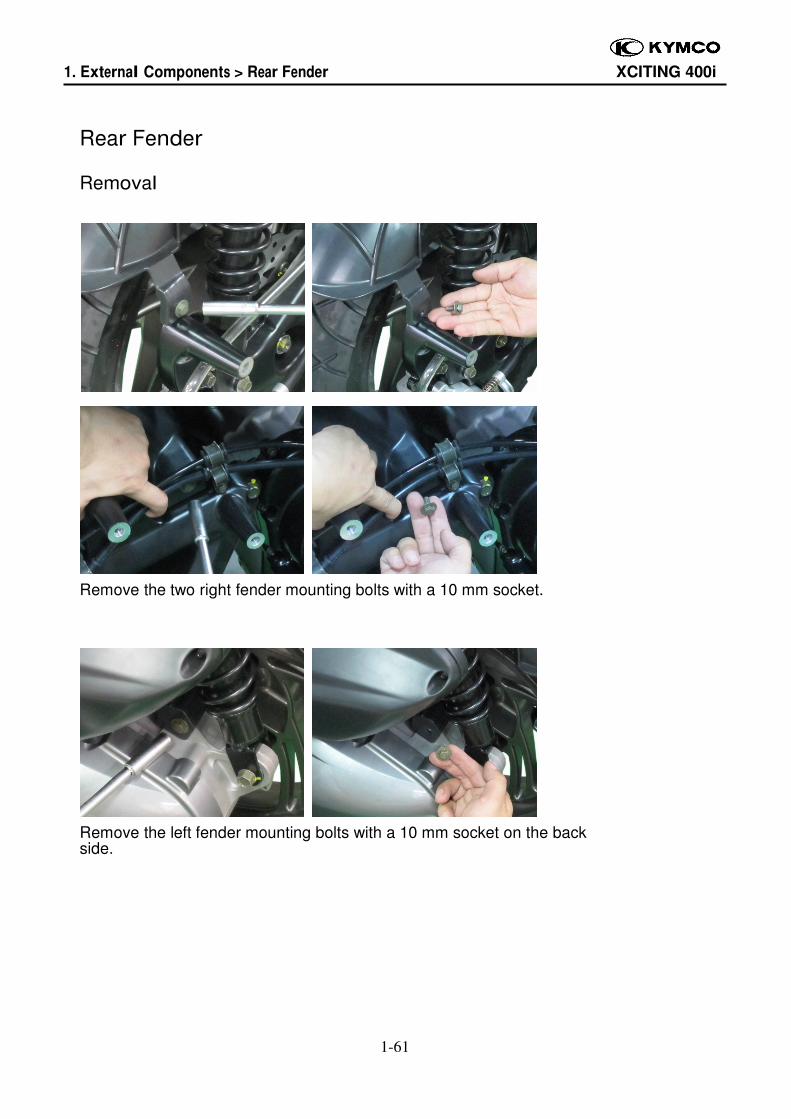
Rear Fender
Removal
Remove the two right fender mounting bolts with a 10 mm socket.
Remove the left fender mounting bolts with a 10 mm socket on the back side.
1. External Components > Rear Fender XCITING 400i
1-62
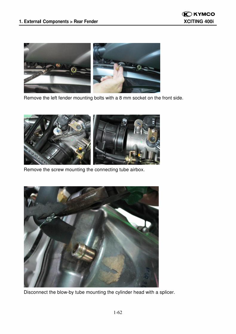
Remove the left fender mounting bolts with a 8 mm socket on the front side.
Remove the screw mounting the connecting tube airbox.
Disconnect the blow-by tube mounting the cylinder head with a splicer.
1. External Components > Rear Fender XCITING 400i
1-63
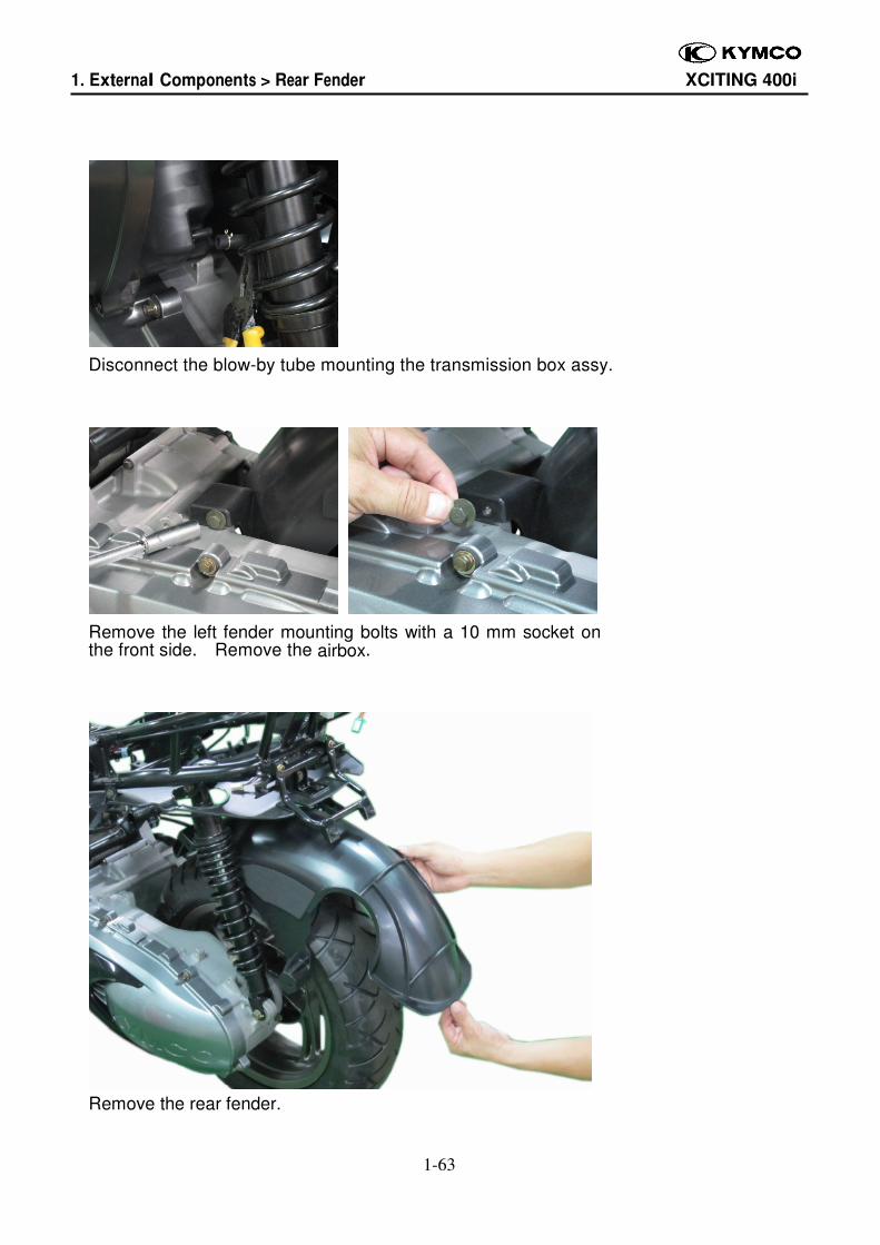
Disconnect the blow-by tube mounting the transmission box assy.
Remove the left fender mounting bolts with a 10 mm socket on the front side. Remove the airbox.
Remove the rear fender.
1. External Components > Rear Fender XCITING 400i
1-64
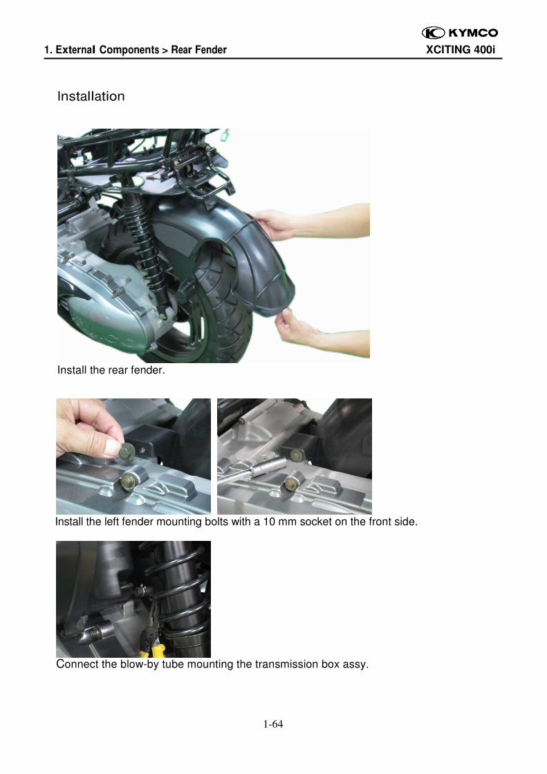
Installation
Install the rear fender.
Install the left fender mounting bolts with a 10 mm socket on the front side.
Connect the blow-by tube mounting the transmission box assy.
1. External Components > Rear Fender XCITING 400i
1-65
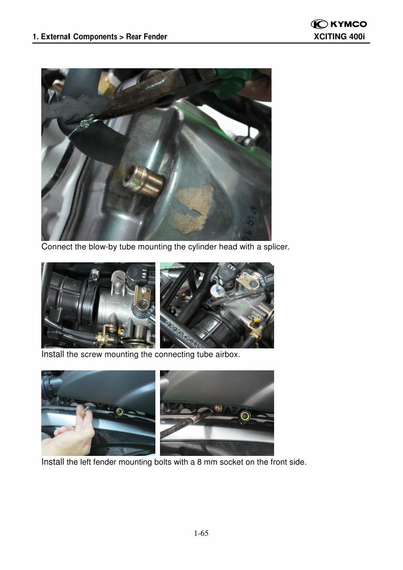
Connect the blow-by tube mounting the cylinder head with a splicer.
Install the screw mounting the connecting tube airbox.
Install the left fender mounting bolts with a 8 mm socket on the front side.
1. External Components > Rear Fender XCITING 400i
1-66
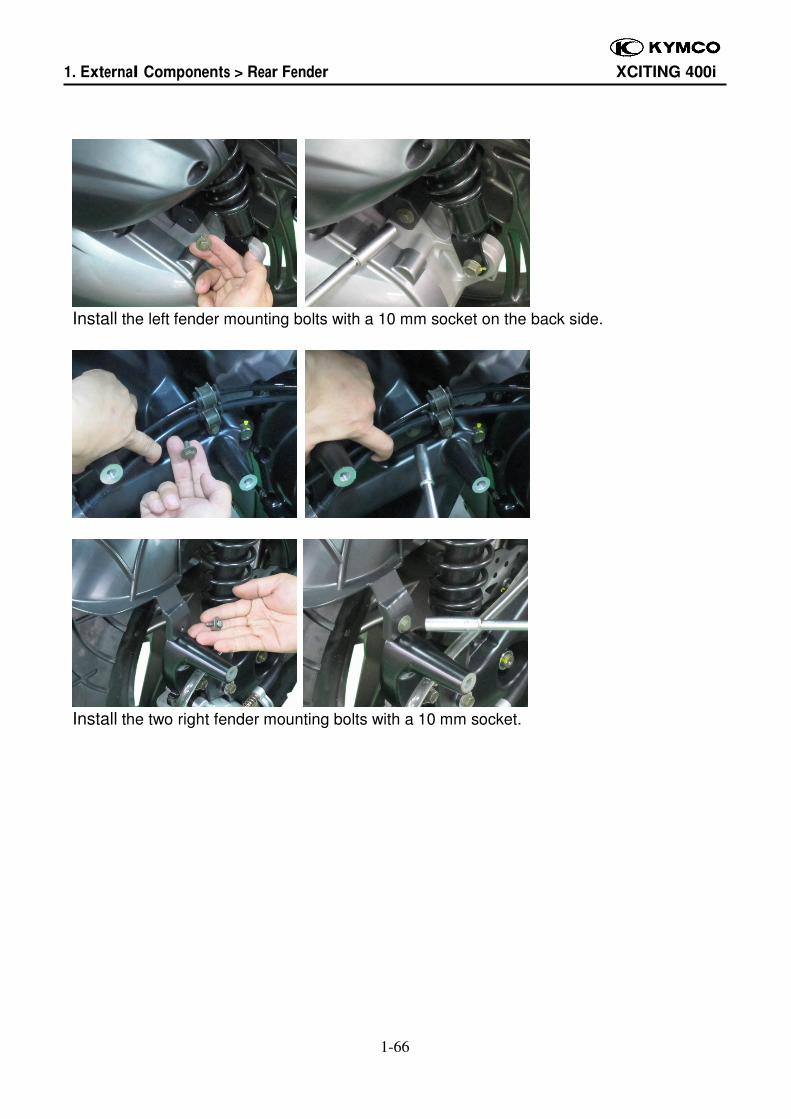
Install the left fender mounting bolts with a 10 mm socket on the back side.
Install the two right fender mounting bolts with a 10 mm socket.
1. External Components > Handlebar Cover XCITING 400i
1-67
Handlebar Covers
Removal
Upper Cover
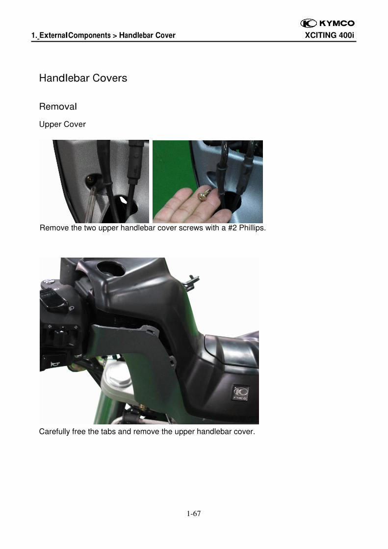
Remove the two upper handlebar cover screws with a #2 Phillips.
Carefully free the tabs and remove the upper handlebar cover.

1. External Components > Handlebar Cover XCITING 400i
1-68
Lower Cover
1. External Components > Handlebar Cover XCITING 400i
1-69
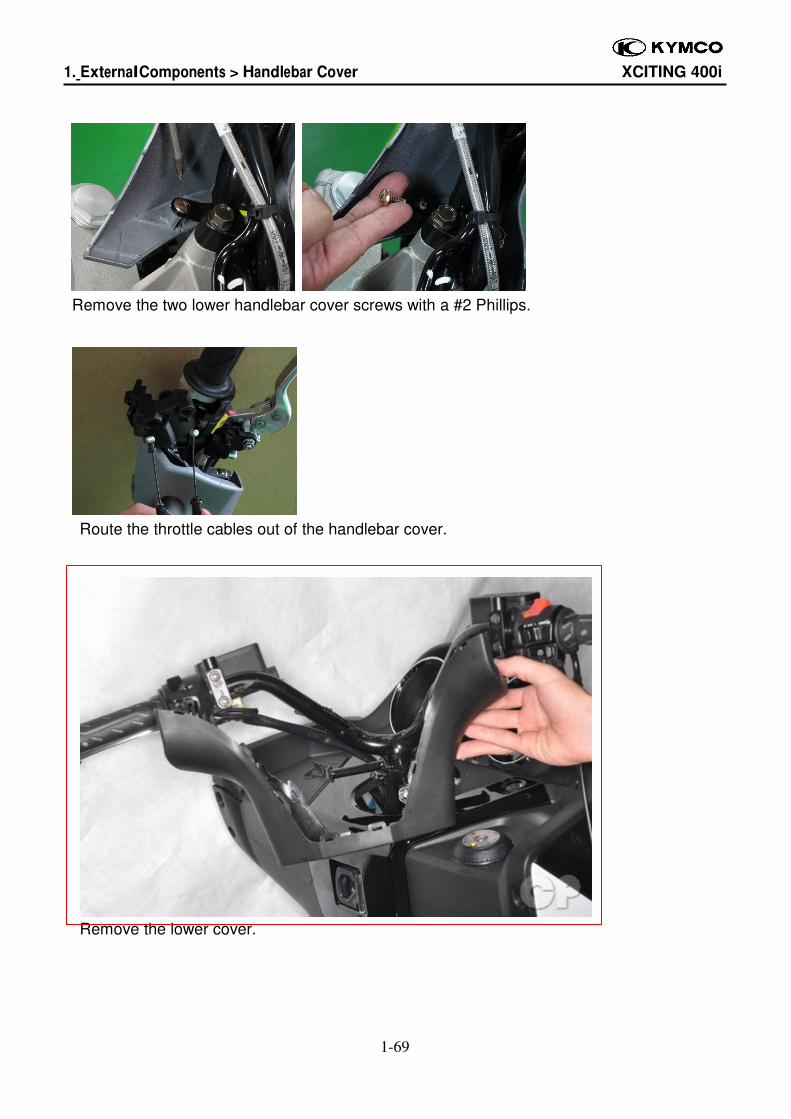
Remove the two lower handlebar cover screws with a #2 Phillips.
Route the throttle cables out of the handlebar cover.
Remove the lower cover.
1. External Components > Handlebar Cover XCITING 400i
1-70
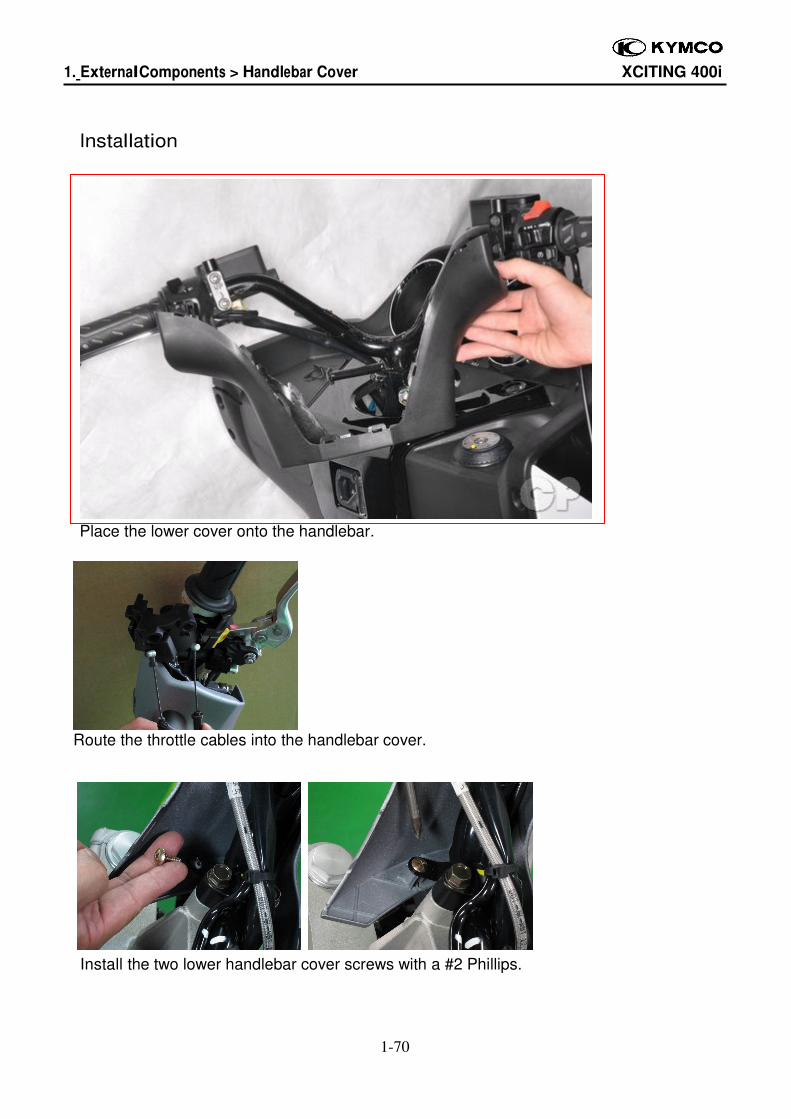
Installation
Place the lower cover onto the handlebar.
Route the throttle cables into the handlebar cover.
Install the two lower handlebar cover screws with a #2 Phillips.
1. External Components > Handlebar Cover XCITING 400i
1-71
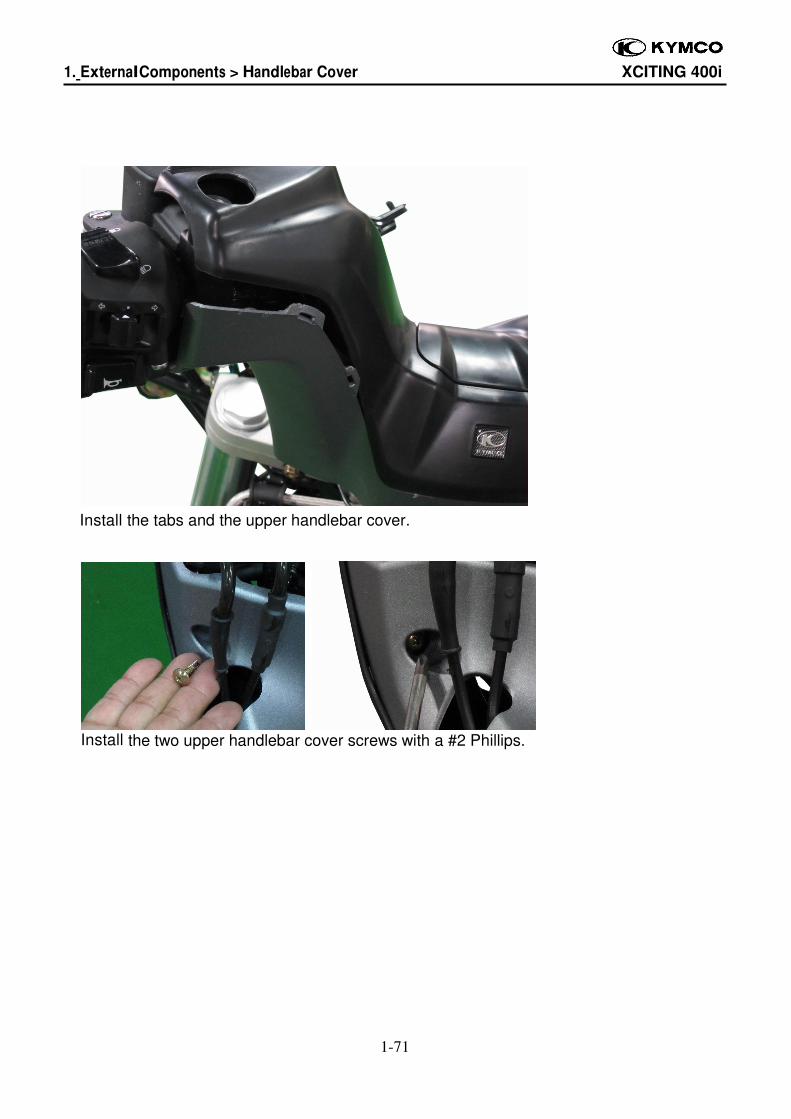
Install the tabs and the upper handlebar cover.
Install the two upper handlebar cover screws with a #2 Phillips.
1. External Components > Under Cover XCITING 400i
1-72
Under Cover
Removal
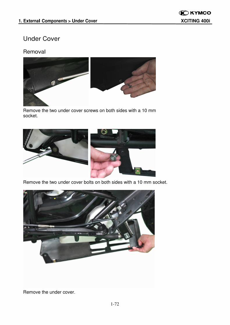
Remove the two under cover screws on both sides with a 10 mm socket.
Remove the two under cover bolts on both sides with a 10 mm socket.
Remove the under cover.
1. External Components > Under Cover XCITING 400i
1-73
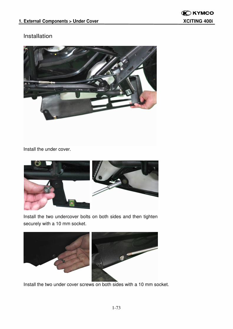
Installation
Install the under cover.
Install the two undercover bolts on both sides and then tighten
securely with a 10 mm socket.
Install the two under cover screws on both sides with a 10 mm socket.

![carmen don.ppt [Read-Only] · CH1:1. CH1:2. CH1:3. CH1:4 DREDGING UFGS SECTION 02325. CH1:5 HOW IT STARTED Corps Spec Steering Committee: Need Suggested Queried Districts Districts:](https://img.pdfslide.us/doc/110x75/5f13e2ca0b294765f40b232e/carmen-donppt-read-only-ch11-ch12-ch13-ch14-dredging-ufgs-section-02325.jpg)