Embed Size (px)
Citation preview
Separator Mohamed salah Page 1
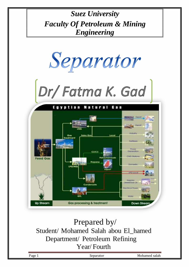
Suez University
Faculty Of Petroleum & Mining Engineering
Prepared by/ Student/ Mohamed Salah abou El_hamed
Department/ Petroleum Refining
Year/ Fourth

Separator Mohamed salah Page 2
Sections of a Gas-Liquid Separator Regardless of the size or shape of a separator, each gas-liquid separator contains four major sections. illustrate the four major sections of a horizontal and vertical two-phase separator, respectively.

Separator Mohamed salah Page 3
Inlet Diverter Section The inlet stream to the separator is typically a high-velocity turbulent mixture of gas and liquid. Due to the high velocity, the fluids enter the separator with a high momentum. The inlet diverter, sometimes referred to as the primary separation section, abruptly changes the direction of flow by absorbing the momentum of the liquid and allowing the liquid and gas to separate. This results in the initial “gross” separation of liquid and gas. Liquid Collection Section The liquid collection section, located at the bottom of the vessel, provides the required retention time necessary for any entrained gas in the liquid to escape to the gravity settling section. In addition, it provides a surge volume to handle intermittent slugs. The degree of separation is dependent on the retention time provided. Retention time is affected by the amount of liquid the separator can hold, the rate at which the fluids enter the vessel, and the
differential density of the fluids. Liquid-liquid separation requires longer retention times than gas-liquid separation. Gravity Settling Section As the gas stream enters the gravity settling section, its velocity drops and small liquid droplets that were entrained in the gas and not separated by the inlet diverter are separated out by gravity and fall to the gasliquid interface. The gravity settling section is sized so that liquid droplets greater than 100 to 140 microns fall to the gas-liquid interface while smaller liquid droplets remain with the gas. Liquid droplets greater than 100 to 140 microns are undesirable as they can overload the mist extractor at the separator outlet. Mist Extractor Section Gas leaving the gravity settling section contains small liquid droplets, generally less than 100 to 140 microns. Before the gas leaves the vessel, it passes through a coalescing section or mist extractor. This section uses coalescing elements that provide a large amount of surface area used to coalesce and remove the small droplets of liquid. As the gas flows through the coalescing elements, it must make numerous directional changes. Due to their greater mass, the liquid droplets cannot follow the rapid changes in direction of flow. These droplets impinge and collect on the coalescing elements, where they fall to the liquid collection section.
Separator Mohamed salah Page 4
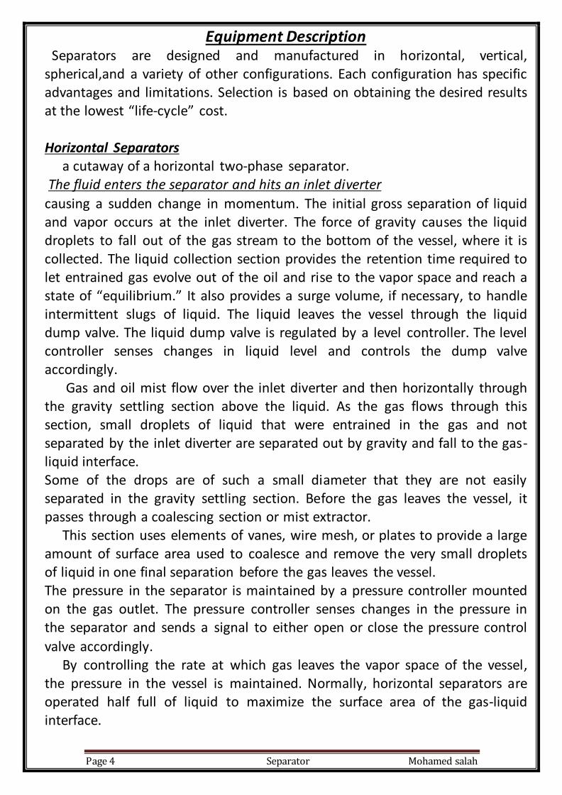
Equipment Description Separators are designed and manufactured in horizontal, vertical, spherical,and a variety of other configurations. Each configuration has specific advantages and limitations. Selection is based on obtaining the desired results at the lowest “life-cycle” cost. Horizontal Separators a cutaway of a horizontal two-phase separator. The fluid enters the separator and hits an inlet diverter
causing a sudden change in momentum. The initial gross separation of liquid and vapor occurs at the inlet diverter. The force of gravity causes the liquid droplets to fall out of the gas stream to the bottom of the vessel, where it is collected. The liquid collection section provides the retention time required to let entrained gas evolve out of the oil and rise to the vapor space and reach a state of “equilibrium.” It also provides a surge volume, if necessary, to handle intermittent slugs of liquid. The liquid leaves the vessel through the liquid dump valve. The liquid dump valve is regulated by a level controller. The level controller senses changes in liquid level and controls the dump valve accordingly. Gas and oil mist flow over the inlet diverter and then horizontally through the gravity settling section above the liquid. As the gas flows through this section, small droplets of liquid that were entrained in the gas and not separated by the inlet diverter are separated out by gravity and fall to the gas-liquid interface. Some of the drops are of such a small diameter that they are not easily separated in the gravity settling section. Before the gas leaves the vessel, it passes through a coalescing section or mist extractor. This section uses elements of vanes, wire mesh, or plates to provide a large amount of surface area used to coalesce and remove the very small droplets of liquid in one final separation before the gas leaves the vessel. The pressure in the separator is maintained by a pressure controller mounted on the gas outlet. The pressure controller senses changes in the pressure in the separator and sends a signal to either open or close the pressure control
valve accordingly. By controlling the rate at which gas leaves the vapor space of the vessel, the pressure in the vessel is maintained. Normally, horizontal separators are operated half full of liquid to maximize the surface area of the gas-liquid interface.
Separator Mohamed salah Page 5
Horizontal separators are smaller and thus less expensive than a vertical separator for a given gas and liquid flow rate. Horizontal separators are commonly used in flow streams with high gas-liquid ratios and foaming crude.
Vertical Separators cutaway of a vertical two-phase separator. In this configuration the inlet flow enters the vessel through the side. As in the horizontal separator, the inlet diverter does the initial gross separation. The liquid flows down to the liquid collection section of the vessel. There are seldom any internals in the liquid collection section except possibly a still well for the level control float or displacer. The still well usually consists of walled box or tube, open on the top and bottom. Its function is to stop wave action in the separator from interfering with the level controller’s operation. Liquid continues to flow downward through this section to the liquid outlet. As the liquid reaches equilibrium, gas bubbles flow counter to the direction of the liquid flow and eventually migrate to the vapor space. The level controller and liquid dump valve operate the same as in a horizontal separator. The gas flows over the inlet diverter and then vertically upward toward the gas outlet. Secondary separation occurs in the upper gravity settling section. In the gravity settling section the liquid droplets fall vertically downward counter-current to the upward gas flow. The settling velocity of a liquid droplet is directly proportional to its diameter. If the size of a liquid droplet is too small, it will be carried up and out with the vapor. Thus, a mist extractor section is added to capture small liquid droplets Gas goes through the mist extractor section before it leaves the vessel. Pressure and level are maintained as in a horizontal separator.

Separator Mohamed salah Page 6
Vertical separators are commonly used in flow streams with low to intermediate gas-liquid ratios. They are well suited for production containing sand and other sediment and thus are often fitted with a false cone bottom to handle sand production. Spherical Separators The same four sections can be found in this vessel. Spherical separators are special case of avertical separator where there is no cylindrical shell between the two heads. Fluid enters the vessel through the inlet diverter where the flow stream is split into two streams. Liquid falls to the liquid collection section, through openings in a horizontal plate located slightly below the gas-liquid interface. The thin liquid layer across the plate makes it easier for any entrained gases to separate and rise to the gravity settling section. Gases rising out of the liquids pass through the mist extractor and out of the separator through the gas outlet. Liquid level is maintained by a float connected to a dump valve. Pressure is maintained by a back pressure control valve while the liquid level is maintained by a liquid dump valve. Spherical separators were originally designed to take advantage, theoretically, of the best characteristics of both horizontal and vertical separators. In practice, however, these separators actually experienced the worst characteristics and are very difficult to size and operate.

Separator Mohamed salah Page 7
They may be very efficient from a pressure containment standpoint, but because (1) they have limited liquid surge capability and (2) they exhibit
fabrication difficulties, they are seldom used in oil field facilities. For this reason we will not be discussing spherical separators any further. Centrifugal Separators Centrifugal separators, sometimes referred to as cylindrical cyclone separators (CCS), work on the principle that droplet separation can be enhanced by the imposition of a radial or centrifugal force. This centrifugal force may range from 5 times the gravitational force in large-diameter units, to 2,500 times the gravitational force in small, high-pressure units. the centrifugal separator consists of three major sections: inclined tangential inlet, tangential liquid outlet, and axial gas outlet. The basic flow pattern involves a double vortex, with the gas spiraling downward along the wall, and then upward in the center. The spiral velocity in the separator may reach several times the inlet velocity. The flow patterns are such that the radial velocities are directed toward the walls, thus causing droplets to impinge on the vessel walls, and run down to the bottom of the unit. The units are designed to handle liquid flow rates between 100 to 50,000 bpd in sizes ranging from 2 to 12 inches in diameter. Centrifugal separators are designed to provide bulk gas-liquid separation. They are best suited for fairly clean gas streams. Fluids are introduced tangentially into the separator via an inclined feed pipe. The high-velocity swirling flow creates a radial acceleration field that causes the gas to flow to the axial core region due to differences in gas and liquid density.
Separator Mohamed salah Page 8
The gas exits through an axial outlet located at the top of the separator, and the liquid leaves through a tangential outlet at the bottom. The feed pipe is inclined at an optimal angle to stratify the inlet flow phases and preferentially direct the liquid flow toward the liquid outlet. To obtain optimal separation performance, the separator requires the liquid level to be maintained within a particular range, which is usually just below the inlet level. The method of level control is dependent on the application, that is, phase composition and location within the process. Control can be achieved by a control valve on either the liquid or the gas outlet lines, or in some applications a level control valve on the liquid outlet line and a pressure control valve on the gas outlet line. The major benefits of centrifugal separators are: no moving parts; low maintenance; compact, in terms of space and weight; insensitive to motion; and low cost when compared to conventional separator technology. Although such designs can result in significantly smaller sizes, they are not
commonly used in production operations because (1) their design is rather sensitive to flow rate and (2) they require greater pressure drop than the standard configurations previously described. Since separation efficiency decreases as velocity decreases, the centrifugal separator is not suitable for widely varying flow rates. These units are commonly used to recover glycol carryover downstream of a glycol contact tower. In recent years, demand for using centrifugal separators on floating production facilities has increased because space and weight considerations are overriding on such facilities. The design of these separators is proprietary and, therefore, will not be covered. Venturi Separators Like the centrifugal, the venturi separator increases droplet coalescence by introducing additional forces into the system. Instead of centrifugal forces, the venture acts on the principle of accelerating the gas linearly through a restricted flow path with a motive fluid to promote the coalescence of droplets. Venturi separators are normally best suited for applications that contain a mixture of solids and liquids. They are not normally cost-effective for removing liquid entrainment alone, because of the high-pressure drop and need for a motive fluid. Even with solids present, the baffle-type units are more suitable for entrained particulates down to 15 microns in diameter.

Separator Mohamed salah Page 9
Double-Barrel Horizontal Separators a double-barrel horizontal separator, which is a variation of the horizontal separator. Double-barrel horizontal separators are commonly used in applications where there are high gas flow rates and where there is a possibility of large liquid slugs, e.g., slug catchers. Single-barrel horizontal separators can handle large gas flow rates but offer poor liquid surge capabilities. The double-barrel horizontal separator partially alleviates this shortcoming. In these designs the gas and liquid chambers are separated.. The flow stream enters the vessel in the upper barrel and strikes the inlet diverter. The gas flows through the gravity settling section, where it encounters the baffletype mist extractors en route to the gas outlet. a cutaway view of a double-barrel separator fitted with a baffle-type mist extractor.
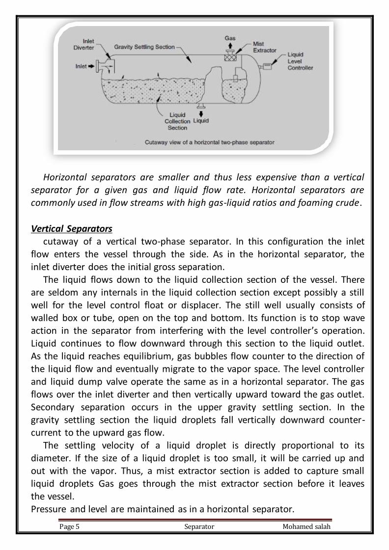
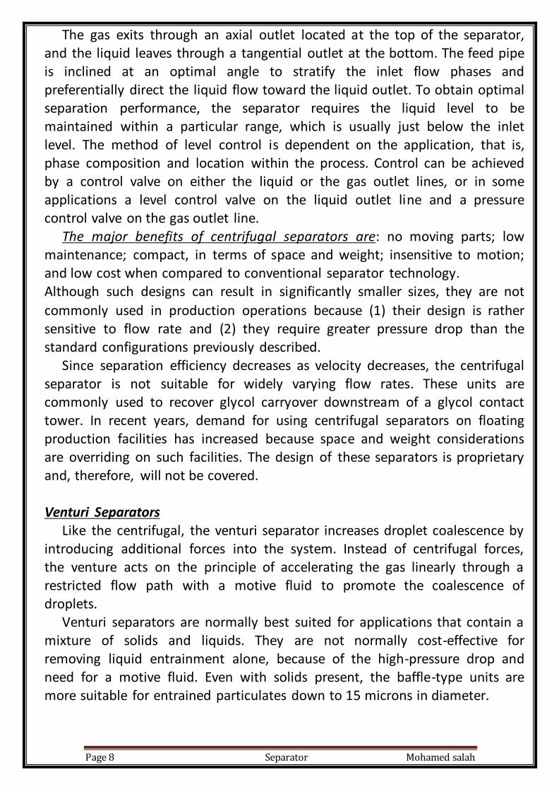
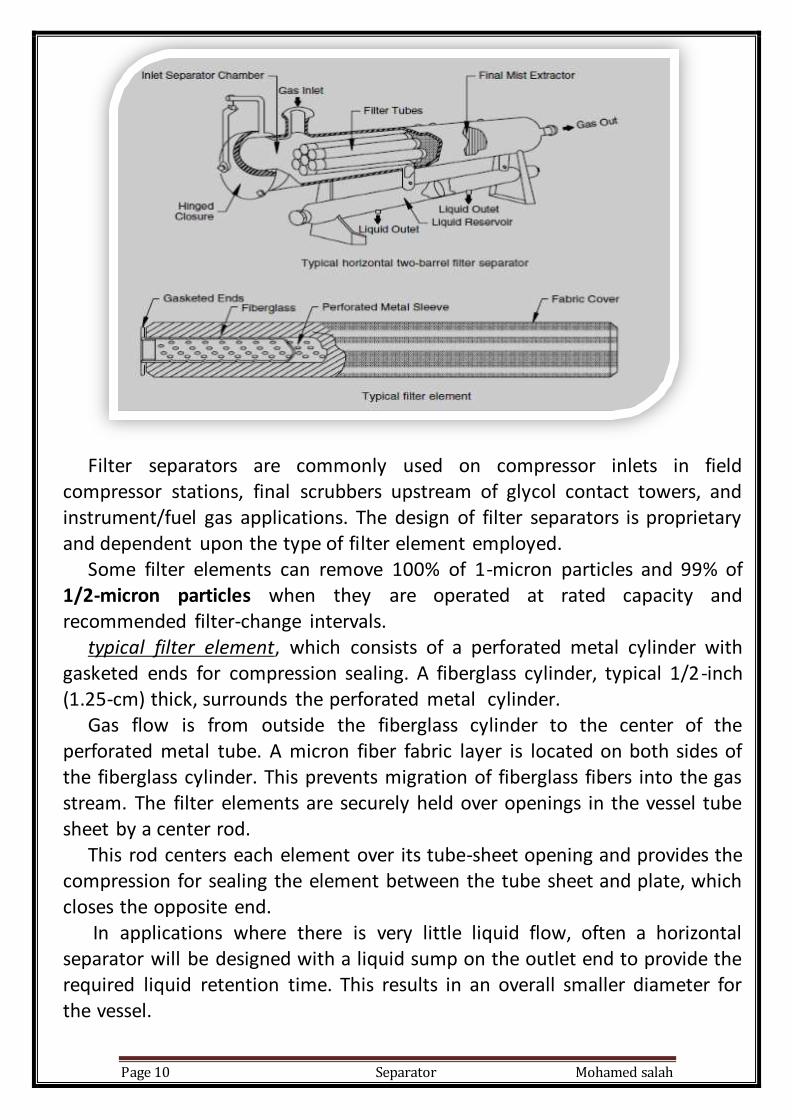
Filter Separators Another type of separator that is frequently used in some high-gas/lowliquid flow applications is a filter separator. They can be either horizontal or vertical in configuration. Filter separators are designed to remove small liquid and solid particles from the gas stream. These units are used in applications where conventional separators employing gravitational or centrifugal force are ineffective.a horizontal twobarrel filter separator design. Filter tubes in the initial separation section cause coalescence of any liquid mist into larger droplets as the gas passes through the tubes. A secondary section of vanes or other mist extractor elements removes these coalesced droplets.
Separator Mohamed salah Page 10
Filter separators are commonly used on compressor inlets in field compressor stations, final scrubbers upstream of glycol contact towers, and instrument/fuel gas applications. The design of filter separators is proprietary and dependent upon the type of filter element employed. Some filter elements can remove 100% of 1-micron particles and 99% of 1/2-micron particles when they are operated at rated capacity and recommended filter-change intervals. typical filter element, which consists of a perforated metal cylinder with gasketed ends for compression sealing. A fiberglass cylinder, typical 1/2-inch (1.25-cm) thick, surrounds the perforated metal cylinder. Gas flow is from outside the fiberglass cylinder to the center of the perforated metal tube. A micron fiber fabric layer is located on both sides of the fiberglass cylinder. This prevents migration of fiberglass fibers into the gas stream. The filter elements are securely held over openings in the vessel tube sheet by a center rod. This rod centers each element over its tube-sheet opening and provides the compression for sealing the element between the tube sheet and plate, which closes the opposite end. In applications where there is very little liquid flow, often a horizontal separator will be designed with a liquid sump on the outlet end to provide the required liquid retention time. This results in an overall smaller diameter for the vessel.

Separator Mohamed salah Page 11
Scrubbers A scrubber is a two-phase separator that is designed to recover liquids carried over from the gas outlets of production separators or to catch liquids condensed due to cooling or pressure drops. Liquid loading in a scrubber is much lower than that in a separator. Typical applications include: upstream of mechanical equipment such as compressors that could be damaged, destroyed or rendered ineffective by free liquid; downstream of equipment that can cause liquids to condense from a gas stream (such as coolers); upstream of gas dehydration equipment that would lose efficiency, be damaged, or be destroyed if contaminated with liquid hydrocarbons; and upstream of a vent or flare outlet. Vertical scrubbers are most commonly used. Horizontal scrubbers can be used, but space limitations usually dictate the use of a vertical configuration. Slug Catchers
A “slug catcher,” commonly used in gas gathering pipelines, is a special case of a two-phase gas-liquid separator that is designed to handle large gas capacities and liquid slugs on a regular basis. Since the gathering systems are designed to handle primarily gas, the presence of liquid restricts flow and causes excessive pressure drop in the piping. Pigging is periodically used to sweep the lines of liquids. When the pigs sweep the liquids out of the gathering lines, large volumes of liquids must be handled by the downstream separation equipment. The separators used in this service are called slug catchers. There are numerous slug catcher designs. a two-phase horizontal slug catcher with liquid “fingers”. Gas and liquid slug from the gathering system enters the horizontal portion of the two-phase vessel, where primary gas-liquid separation is accomplished. Gas exits the top of the separator through the mist extractor while the liquid exits the bottom of the vessel through a series of large-diameter tubes or “fingers”. The tubes provide a large liquid holding volume and routes the liquid to a three-phase free-water knockout (FWKO) for further liquid-liquid separation.

Separator Mohamed salah Page 12
Selection Considerations The geometry of and physical and operating characteristics give each separator type advantages and disadvantages. Horizontal separators are smaller, more efficient at handling large volumes of gas, and less expensive than vertical separators for a given gas capacity. In the gravity settling section of a horizontal vessel, the liquid droplets fall perpendicular to the gas flow and thus are more easily settled out of the gas continuous phase. Also, since the interface area is larger in a horizontal separator than a vertical separator, it is easier for the gas bubbles, which come out of solution as the liquid approaches equilibrium, to reach the vapor space. Horizontal separators offer greater liquid capacity and are best suited for liquid-liquid separation and foaming crude. Thus, from a pure gas/liquid separation process, horizontal separators would be preferred. However, they do have the following drawbacks, which could lead to a preference for a vertical separator in certain situations:
1.Horizontal separators are not as good as vertical separators in handling solids. The liquid dump line of a vertical separator can be an alternative, a drain could be placed at this location so that solids could be disposed of periodically while liquid leaves the vessel at a slightly higher elevation.
2. In a horizontal vessel, it is necessary to place several drains along the length of the vessel. Since the solids will have an angle of repose of 45_ to 60_, the drains must be spaced at very close intervals. Attempts to lengthen the distance between drains, by providing sand jets in the vicinity of each drain to fluidize the solids while the drains are in operation, are expensive and have
been only marginally successful in field operations.
3. Horizontal vessels require more plan area to perform the same separation as vertical vessels. While this may not be of importance at a land location, it could be very important offshore. If several separators are used, however, this disadvantage may be overcome by stacking one horizontal separator on top of each other.
4. The ability of a separator to absorb a slug of liquid is called the surge capacity of a separator. Smaller, horizontal vessels can have less liquid surge capacity than vertical vessels sized for the same steady-state flow rate.

Separator Mohamed salah Page 13
For a given change in liquid surface elevation, there is typically a larger increase in liquid volume for a horizontalseparator than for a vertical separator sized for the same flow rate. However, the geometry of a horizontal vessel causes any highlevel shut-down device to be located close to the normal operating level. In very large diameter [greater than 6 ft (1.8 m)] horizontal vessels and in vertical vessels, the shut-down device could be placed much higher, allowing the level controller and dump valve more time to react to the surge. In addition, surges in horizontal vessels could create internal waves, which could activate a high-level sensor prematurely. It should be pointed out that vertical vessels also have some drawbacks that are not process related and must be considered in making a selection.
These are as follows: 1. The relief valve and some of the controls may be difficult to service without special ladders and platforms.
2. The vessel may have to be removed from a skid for trucking due to height restrictions. Generally, horizontal separators are less expensive than equally sized vertical separators. Since vertical separators are supported only by the bottom skirt , the walls of vertical separators must be somewhat thicker than a similarly sized and rated horizontal separator, which may be supported by saddles. Furthermore, large vertical separators, when exposed to high winds, can be subjected to large lateral (wind) loads. When this is the case, the vertical separator’s wall thickness must be increased, which in turn increases the cost of the overall vessel. The same discussion regarding gas capacity applies equally to the double-barrel horizontal separator. The addition of the second barrel increases the vessel’s surge capacity. Spherical separators have more gas capacity than similarly sized vertical separators but less than similarly sized horizontal separators. They have less surge capacity than similarly sized horizontal separators. Installation and operation of level controls on spherical separators are difficult. Few spherical separators are still in existence today. Overall, horizontal vessels are the most economical for normal oil-gas separation, particularly where there may be problems with emulsions, foam, or high gas-oil ratios (GOR). Vertical vessels work most effectively in low-GOR applications. They are also used in some very high GOR applications, such as scrubbers where only fluid mists are being removed from the gas and where extra surge capacity is needed to allow shutdown to activate before liquid is carried out the gas outlet (e.g., compressor suction scrubber).

Separator Mohamed salah Page 14
Separator Components