Embed Size (px)
Citation preview

INTRODUCTION : INTRODUCTION OF THE ORGANISATION
AIM & ESTABLISHMENT OF THE COMPANYCentral Electronics Limited is a public sector Enterprise under the Department of Scientific and Industrial Research (DSIR), Ministry of Science & Technology, Government of India. It was established in 1974 with an objective to commercially exploit the indigenous technologies developed by national laboratories and R & D Institutions in the country. CEL is one of the rare companies which utilized the homegrown technologies during all these years of its existence
CEL has developed a number of products for the first time in the country through its own R&D efforts and in close association with the premier National & International laboratories including Defense laboratories. In recognition of all these efforts, CEL has been awarded a number of times with prestigious awards including
“NATIONAL AWARD for R&D by DSIR”. CEL is pioneer in the country in the field of Solar Photovoltaic (SPV) and it has developed state of the art technology with its own R&D efforts. Its solar products have been qualified to International Standards EC503/IEC1215 by the European Commission, joint Research center, and ISPRA, ITALY.
CEL, pioneer in the field of Railways Safety & Signaling, has been identified as a major indigenous agency for design an development of modern electronic signaling and safety equipment by Indian Railways. The equipment manufactured in CEL finds extreme usage in Railways in the form of Axle Counter, Axle Counter Block System and Train Approach Warning devices. CEL’s Digital Axle Counter is approved as per European CENELEC safety level SIL-4 by RDSO(Research Design and Standard Organization of Indian Railways )as an approved source in part-1 for various railway safety and signaling equipments for more than 25 years.
CEL has developed a number of critical components for strategic application and is supplying these items to Defense.
1

PROFILE
ORGANIZATION STRUCTURE OF CEL
CHAIRMAN & MANAGING DIRECTO
GENERAL MANAGER(CP &HRD)
Jt.GENERAL MANAGER (FINANCE)
Jt.GENERAL MANAGER (MATERIAL MGMT)
EXECUTIVE DIRECTOR(OPERATION)
AGM(QUALITY ASSURANCE)
GENERAL MANAGER (PROJECT MNGMT)
GENERAL MANGER (SYSTEMS)
Jt.GENERALMANAGER(MICROWAVE)
AGM(FERRITE)
GENERAL MANAGER(SPV)
Jt.GENERAL MANAGER (R&D)
Jt.GM(CERAMICS)
2

CP/ HRD - Corporate Planning & Human Resource Development
MMD - Material Management Division
FAD - Finance & Account Division
R & D - Research & Development
SPVG - Solar Photo Voltaic Group
MED - Microwave Electronics Division
PFD - Professional Ferrite Division
CP Project - Cathodic Protection Project
Rly. Project - Railway Project
QC - Quality Control
PEG - Production Engineering Group
W/S - Work Shop
PPC - Production Planning Control
DIVISIONS OF CEL
3

Five business groups handle the total commercial operations of the Company. These are as follows:
SOLAR PHOTOVOLTAIC GROUP (SPV):
CEL, backed by an integrated production facility, has opened up new horizons in the field of Solar Photovoltaics. It fulfils the various demands from rural & urban areas, thus, harnessing the solar energy. The products of this division are Solar Cells, Modules and systems, which serve the industrial needs of Railway Signaling, Microwave Repeaters, Defence equipments, Obstruction warning lights at airports, etc. and rural needs such as pumping systems for irrigation, street lighting systems, solar lanterns and rural telecommunications.
ELECTRONIC SYSTEMS GROUP (ESG):
The Company is a pioneer in manufacturing of Railway Signaling and Safety Equipments. It manufactures Axle Counters, Railway Level Crossing Warning System, Solid State Interlocking System for Railways. The other products of this division include Electronic Switching System, Cathodic Protection System for underground pipelines and VSAT.
COMPONENTS GROUP:
4

A large range of products is manufactured here using state-of-art technologies to meet the requirements of communications, defense, consumer and industrial sectors.
It is divided into three sub departments. Their products and applications are as follows:
(a) Professional Ferrites:
This department manufactures different types of ferrite cores for high frequency applications. The different types of cores manufactured are Pot cores, E, U, I, RM, torroids etc. These are called professional because they require highly sophisticated techniques for their manufacture and give a superior performance. The various applications of ferrite cores include TV sets, Communication equipments, computers, electronic ballasts, switch mode power supplies (SMPS) and Microwave equipments.
(b) Electronic Ceramic s :
This department manufactures piezo-electric transducer elements, high temperature crucibles, high speed bearings and other alumina products. These products are used in Defense ammunitions, Ultrasonic cleaners, Buzzers, Sonars, Gas Lighters, Automobiles, etc.
(c) Microwave Electronics :
This department manufactures microwave components such as Phase Shifters used in Radars, Direction Finding Systems, Frequency Correlators, Antennas, etc.
PRODUCTS OF CEL
5

The organization manufactures different products that can be classified according to the divisions of CEL as follows:
Solar Photovoltaic Group :
Solar Lantern Street Light System Home Light System Water Pumping System
Electronic Systems Group :
Single / Multiple Entry / Exit Axle counters Universal Axle counters Block proving system Railway Level Crossing Warning system Solid State Interlocking System for Railways Cathodic Protection system Very Small Aperture Terminal (VSAT) Electronic Switching Equipments
Components Group :
Different types of ferrite cores like Pot, RM, E, U, I, etc Piezoelectric transducer elements Special Bearings used in Heavy Water Plants Microwave Ferrite Phase shifters Direction Finding Systems Frequency / Phase Correlators7
NATION’S PIONEER & WORLD LEADER IN SOLAR PHOTOVOLTAIC
6

In an era of growing energy needs and rising concern for environment,
solar energy, the abundant and pollution free non-conventional energy source, offers
the best alternative solution.
CEL, with its commitment to harness the solar energy, has
Backed by an integrated production facility, CEL has made accumulative supply
of over 1.5 lakhs SPV systems (20 MW) spread over 28 different types, covering
both rural and industrial applications. The company has not only given a fillip to
the Indian SPV market but also exported products to Indonesia, Bhutan,
Bangladesh, Egypt, Cuba, Nepal, opened up new vistas in the field of solar
photovoltaics; CEL is the poignant and the largest producer of solar photovoltaics.
Mali, Columbia and Costa Rica.
CEL has successfully transferred technology for manufacturing SPV Modules and
Systems to Rajasthan Electronics & Instruments Ltd. India in 1985 and very
recently to Scientific Studies and Research Center (SSRC), Syria in May 1997.
This is the first case of SPV Technology Export from the Developing World.
CEL’s SPV Modules conform to the international specifications –JPL
Block Vand IEC specification No. CEI / IEC 61215. CEL SPV Modules
were certified by European Solar Test Installations (ESTI), JRC Ispra, Italy.
INNOVATIVE ELECTRONIC SYSTEMS
7

Signalling & Safety Systems for the Indian Railways :-
CEL is the pioneer Public Sector Company supplying Railway
Signaling and Safety equipments to Indian Railways.
CEL continually identifies new requirements of the Railways and
develops / manufactures the same in association with Research, Design
and Standards Organization (RDSO)and Railway Board.
The Company is currently engaged in development of Digital Axle
Counter in association withRDSO and Department of Scientific
Industrial Research (DSIR).
The product is undergoing extensive field trials in different zones of Indian Railways and
software validation is under progress. The product is expected to be deployed in Indian
Railway’s Signalling network in large numbers by the end of year 2002.
Cathodic Protection Systems :-
CEL supplies Automatic Cathodic Protection Systems for the protection of oil / gas
pipelines to organizations like Indian Oil Corporation, ONGC and GAIL.
The Company supplies different types of Cathodic Protection Systems operating with
solar photovoltaic or thermoelectric power sources or operating on grid supply.
QUALITY POLICY
8

The complete manufacturing operation, marketing and installation services of the
company is certified under ISO 9002 : 1994. The company has enunciated the following
quality policy to meet customer needs and expectations through supply of quality
products and services.
“CEL is committed to strive for leadership in the product marketed by the way of
continuous improvements in the quality of its products and services and meeting the
consumers needs in time and every time at a competitive price.
These shall be achieved through continuous upgrading of technology and process
improvement by involving all the employees, vendors, dealers and customers.
Quality is our basic business principle.”
9

UNIVERSAL AXLE COUNTERFOR RAILWAYS
10

Universal Axle Counter ACS - 55 / 56 / 57 INTRODUCTION Axle counters were developed as a substitute for track circuiting. Initially axle counters were imported from Germany to gain experience and to evaluate their suitability for adoption on Indian Railways. Having gained acceptability for introduction on a wide scale on Indian Railways, it was considered to take up indigenous development of axle counters, which was taken up in collaboration with IIT, Delhi and DOE. Two models of axle counters known as single entry/exit axle counter and multi entry/exit axle counters emerged and after extensive laboratory and field trails under various conditions, the design was finalized and commercialized through private sector as well as public sector.
Based on the feedback from field, a new axle counter has been developed by RDSO, known as “UNIVERSAL AXLE COUNTER”.
NEED FOR AXLE COUNTERS :
The track circuits are considered as the vital components of signaling system to achieve safety of train operations. Various Accident Enquiry Committees have recommended to bring more and more tracks under track circuiting to safeguard against reception of trains on occupied lines. The track circuiting could not achieve desired progress due to virtual scarcity of wooden sleepers, prohibitive cost and environmental consciousness in the country and the world at large. Availability of concrete sleepers have solved the problem to some extent but track circuiting on loop lines, points and crossings still suffers for want of adequate supply and insertion of concrete sleepers.
ADVANTAGES :
The advantages of Axle Counter over a conventional track circuit are: (i) It does not require wooden sleepers (where concrete sleepersare not available) except for short track circuits to suppress thecounts due to movement of insulated trolleys.
11

(ii) An Axle Counter System can cover a very long section of upto 15 km as compared to 750 mtrs. of maximum length of operation of conventional track circuit.
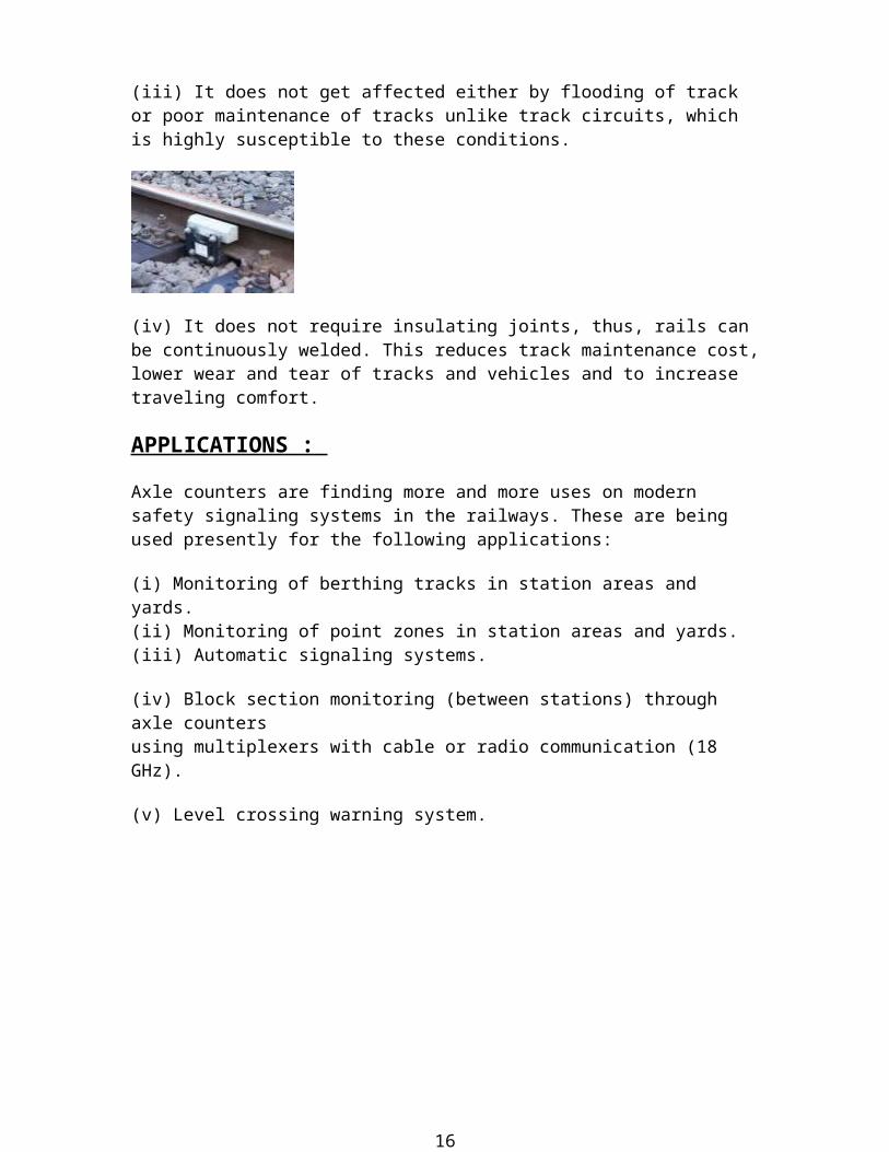
(iii) It does not get affected either by flooding of track or poor maintenance of tracks unlike track circuits, which is highly susceptible to these conditions.
(iv) It does not require insulating joints, thus, rails can be continuously welded. This reduces track maintenance cost, lower wear and tear of tracks and vehicles and to increase traveling comfort.
APPLICATIONS :
Axle counters are finding more and more uses on modern safety signaling systems in the railways. These are being used presently for the following applications:
(i) Monitoring of berthing tracks in station areas and yards.(ii) Monitoring of point zones in station areas and yards.(iii) Automatic signaling systems.
(iv) Block section monitoring (between stations) through axle counters using multiplexers with cable or radio communication (18 GHz).
(v) Level crossing warning system.
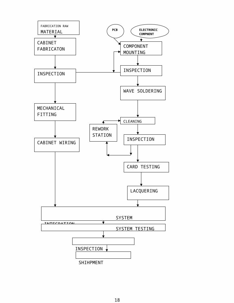
FLOW CHART FOR MANUFACTURING OF AXLE COUNTER
12
COMPONENT MOUNTING
INSPECTIONINSPECTION
WAVE SOLDERING
CLEANING
CABINET FABRICATON
INSPECTION
CARD TESTING
LACQUERING
SYSTEM INTEGRATION
MECHANICAL FITTING
CABINET WIRING
REWORK STATION
SYSTEM TESTING
INSPECTION
SHIHPMENT
FABRICATION RAW MATERIAL ELECTRONIC
COMPNENTPCB
13

EVALUATOR
PRINCIPLE OF OPERATION Signal aspect for train movement is controlled based on clear or occupied status of the track section. If a train occupies the track section, signal at the entry point of the section is made RED and the next train is stopped from entering into the section. When the track section is clear the signal is made GREEN and the train is allowed to proceed into the section.
The clear or occupied condition of the track section is decided by Axle Counter by counting the number of axles of train at entry and exit points of the section. The axle counter compares the IN and OUT counts and in case of count equality TRACK CLEAR signal is given. In all other conditions TRACK OCCUPIED signal is given.
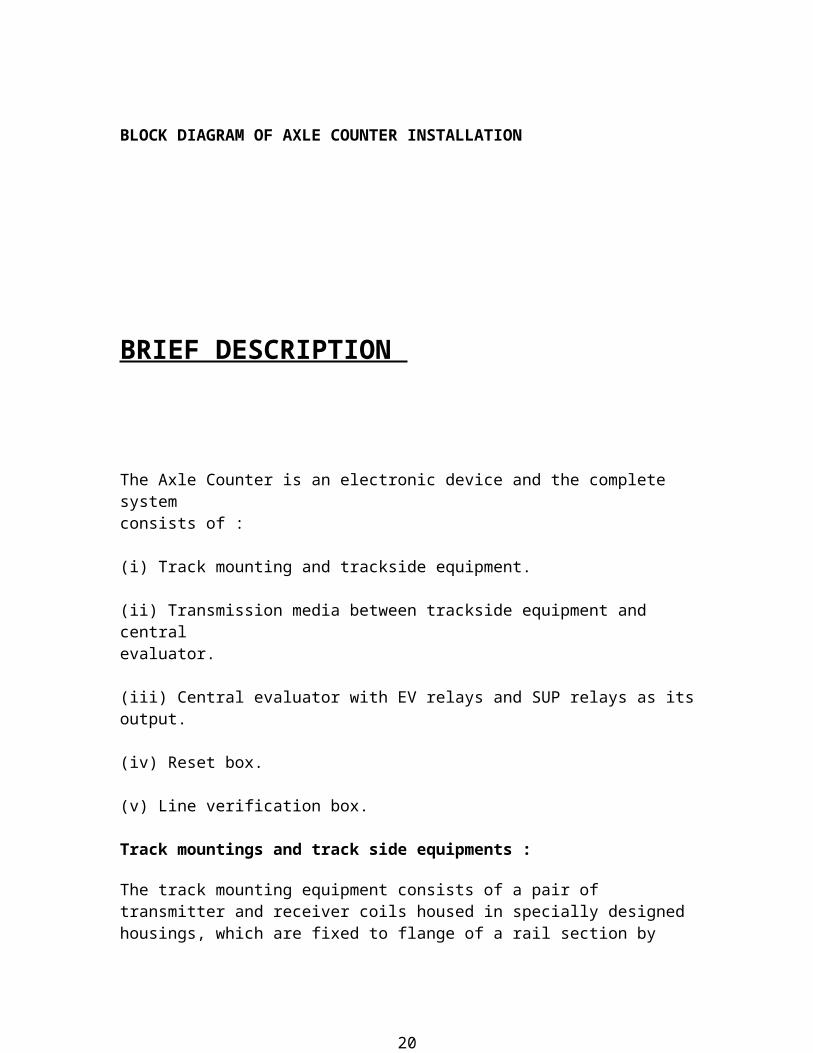
BLOCK DIAGRAM OF AXLE COUNTER INSTALLATION
14

BRIEF DESCRIPTION
The Axle Counter is an electronic device and the complete system consists of :
(i) Track mounting and trackside equipment.
(ii) Transmission media between trackside equipment and central evaluator.
(iii) Central evaluator with EV relays and SUP relays as its output.
(iv) Reset box.
(v) Line verification box.
Track mountings and track side equipments :
The track mounting equipment consists of a pair of transmitter and receiver coils housed in specially designed housings, which are fixed to flange of a rail section by means of suitable rail clamps using bolts and nuts. Each detection point has two sets of such tracks devices mounted on same rail with a fixed stagger between them. The two transmitter coils of a detection point are connected in series to 5 kHz oscillators housed in electronic junction box which is installed in a location box by the side of the track. The output of two receiver coils of a detection point serve as inputs to two receivers amplifiers housed in the same electronic junction box through cables which are part of the track mounting equipment. Electronic junction box is powered by 24 V DC supply.
Transmission media between trackside equipment and central evaluator : The connection between trackside equipment and central evaluator is made using balanced twin twisted quad cables of specification IRS: TC/41/90. The output of electronic junction box and input of central evaluator are matched for an impedance of about 180 ohms at 5 kHz.
There is attenuation of signal from electronic junction box to central evaluator, which limits the length of the cable. Other media such as optic fiber and wireless system may also be used in place of cable by incorporating appropriate interfacing equipment at transmitting and receiving ends.
Central evaluator with EV relay and SUP relay as its output :
15
The signals received from electronic junction boxes are processed in the central evaluator first by analog circuits and then by digital circuits to produce suitable output in terms of picking up or dropping of EV and SUP relays. The Dip’s generated by wheels as they pass over the track
devices installed at detection points, after they get processed, generate count pulses in a fail safe manner.
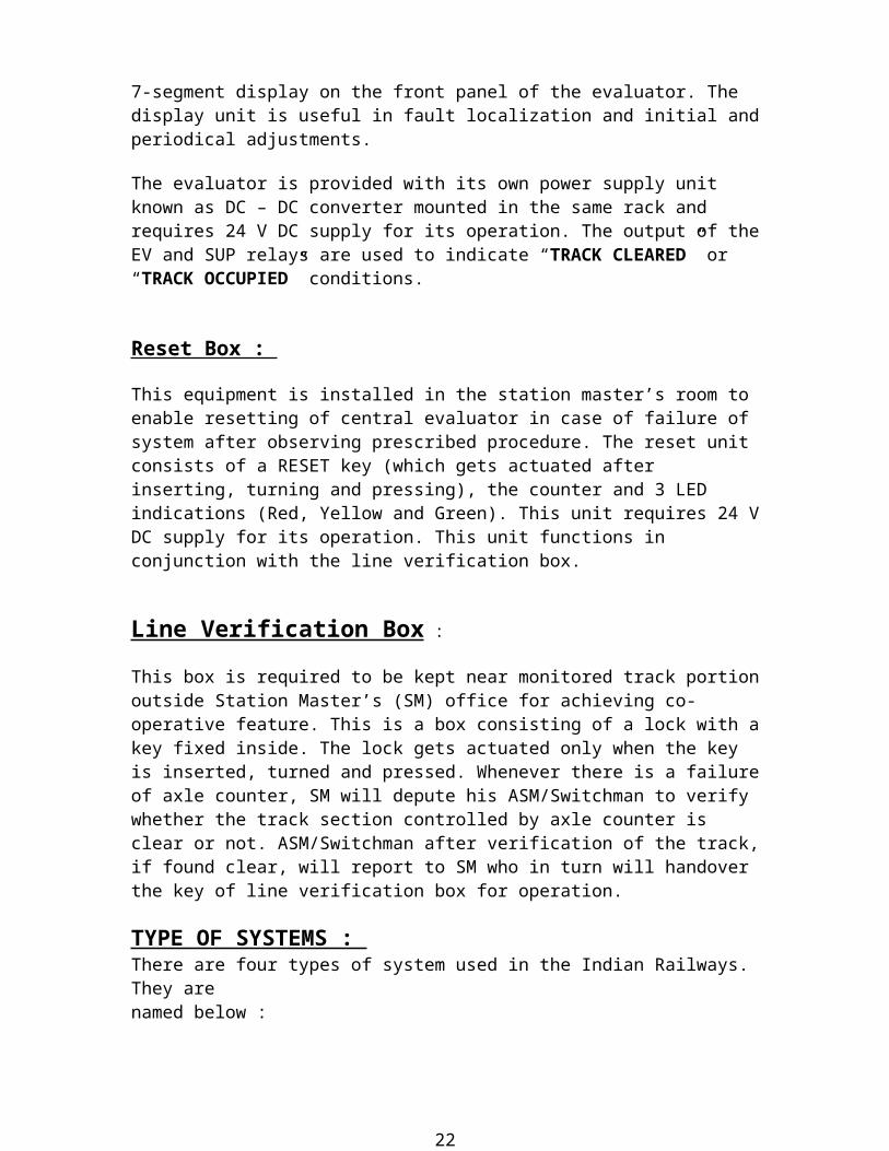
These pulses are identified as ‘IN COUNTS’ or ‘OUT COUNTS’ depending on the direction of movement of vehicles over the monitored section. The counts are also displayed through the 7-segment display on the front panel of the evaluator. The display unit is useful in fault localization and initial and periodical adjustments.
The evaluator is provided with its own power supply unit known as DC – DC converter mounted in the same rack and requires 24 V DC supply for its operation. The output of the EV and SUP relays are used to indicate “TRACK CLEARED” or “TRACK OCCUPIED” conditions.
Reset Box :
This equipment is installed in the station master’s room to enable resetting of central evaluator in case of failure of system after observing prescribed procedure. The reset unit consists of a RESET key (which gets actuated after inserting, turning and pressing), the counter and 3 LED indications (Red, Yellow and Green). This unit requires 24 V DC supply for its operation. This unit functions in conjunction with the line verification box.
Line Verification Box :
This box is required to be kept near monitored track portion outside Station Master’s (SM) office for achieving co-operative feature. This is a box consisting of a lock with a key fixed inside. The lock gets actuated only when the key is inserted, turned and pressed. Whenever there is a failure of axle counter, SM will depute his ASM/Switchman to verify whether the track section controlled by axle counter is clear or not. ASM/Switchman after verification of the track, if found clear, will report to SM who in turn will handover the key of line verification box for operation.
TYPE OF SYSTEMS : There are four types of system used in the Indian Railways. They are named below : (i) One Device (1-D) System.
(ii) Two Device (2-D) System.
16

(iii) Three Device (3-D) System.
(iv) Four Device (4-D) System.1-D System:
In this system, there is a common detection point at entry and exit point of monitored section. This system is useful for monitoring the berthing track of terminal yard. A train after passing the detection point generates pulses equal to axles in it and these pulses are counted and stored by the evaluator as ‘IN COUNTS’.
At the time of exit of train, the same detection point will be encountered and it generates the same number of pulses as that during the entry. These pulses are counted and recorded as ‘OUT COUNTS’ by the evaluator. When the IN COUNTS and OUT COUNTS are equal, the system gives a
“Track clear” indication, otherwise it gives the “Track occupied” indication.
2-D System :
The principle of working of this system is similar to 1-D System except that in this system there are two detection points, one at each end of the monitored section. This system is useful for providing track circuiting on berthing track.
3-D System :
In this system, there are three detection points. The principle of working of this system is similar to 2-D system. This system is useful for providing track circuitry on points, crossings and sidings.
4-D System :
In this system, there are four detection points. The principle of working of this system is similar to 2-D system. The system is useful for providing track circuiting on branch lines, sidings and points and diamond crossings.
The design of 4-D system is such that it can be converted into a 2-D system or a 3-D system and vice–versa.
SPECIFICATIONS
Universal Axle Counter System mainly comprises of following equipments :
17
1. Rack, ACS-55/56/57 -- (Common type for all models) 1 No.
2. Evaluator -- EV – 542 / 543 / 544 1 No.
3. DC-DC converter -- (inside Evaluator only as 10th Card) 1 No. 4. Electronic Junction -- for 2D system (ACS-55-2D) box , JB-533 2 No. -- for 3D system (ACS-56-3D) 3 Nos. -- for 4D system (ACS-57-4D) 4 Nos. 5. Reset box -- RB – 257B 1 No.
6. Track Device -- for a 2D system (ACS-55-2D) 2 Nos. Assembly -- for a 3D system (ACS-56-3D) 3 Nos. TR – 556 -- for a 4D system (ACS-57-4D) Nos.
7. Line verification box -- LV – 261 1 No.
PARAMETER SPECIFICATIONS
1. No. of Detection Points ACS-55 / 56 / 57 2 / 3 / 4
2. Maximum Train Speed 200 kmph
3. Counting Capacity 1023
4. Max. Line Attenuation (over cable) 20 dB
5. Signal Input (5 KHz) sinusoidal Min. 150 mv.rms Max. 1500 mv.rms
6. Relay Drive Voltage for 1000 ohm Shelf type 4F / 4B relay or Q Style > 10 V Plug in Relay 1000 ohm, 4F / 4B
18

Power Requirement :
Powers required by various units are as follows :
DC – DC Converter 1.5 Amp max. 24 V (-10% to +20%)
Evaluator 24 V 1.5 Amps (21.6 – 28.8 V DC)
Junction Box 24 V < 250 mA (21.6 – 28.8 V DC)
Reset Box 24 V 500 mA (21.6 – 28.8 V DC) (only when reset key is pressed)
Environmental Conditions :
Relative Humidity 95 % - 98% Non Condensing
Temperature range :
19
Universal Evaluator 0 to + 60 ˚C
Junction Box & Track Devices 0 to + 70 ˚C
DESCRIPTION OF VARIOUS MODULES OF AXLE COUNTER SYSTE
1. EVALUATOR :
The Evaluator consists of 10 PCB modules. The interconnections between the various PCB cards are made with the help of a motherboard. The polarization arrangement (to avoid wrong insertion of modules) is provided on the aluminum modular sheets in each. Hence it is important to ensure correct fitting of modular shield in each card. In the Universal Axle Counter System manufactured by Central Electronics Limited , relevant card number has been number punched for easy identification to ensure correct fitting of modular shields. A brief description of each P.C. assembly is given below.
(a) Attenuator/Amplifier & Rectifier Card (Card no. 1) :
This is a double sided PCB (Size: 225mm X 275mm). It contains four identical channels , each comprising of a 5 kHz high pass filter , a line matching transformer, attenuator pads, a two stage amplifier and a full wave rectifier. The output of each channel can be set precisely by means of a lockable shaft potentiometer mounted at the front end of the PCB module. Typical output is 300 mv (P-P) or 105-mv rms.
(b)Attenuator/Amplifier & Rectifier Card (Card no. 2) :
This is a double sided PCB (Size: 225mm X 275mm). It contains four identical channels , each comprising of a 5 kHz high pass filter , a line matching transformer, attenuator pads, a two stage amplifier and a full wave rectifier. The output of each channel can be set precisely by means of a lockable shaft potentiometer mounted at the front end of the PCB module. Typical output is 300 mv (P-P) or 105-mv rms.
For 1D and 2D Systems, there will be one such card (Card no. 1) while for 3D and 4D Systems, the evaluator will have two nos. of such cards (Card nos. 1 & 2).
20

(c) Pulse Shaper Card (Card no. 3) :
This is a double sided PCB (Size: 225mm X 275mm). It contains four identical channels, each consisting of a low pass filter, a Schmitt trigger, an impulse time filter and a 10 V to 5 V level converter. The outputs of these channels are TTL compatible. In addition to above, each channel comprises of a Trolley Suppression Circuit.
(d)Pulse Shaper Card (Card no. 4) :
This is a double sided PCB (Size: 225mm X 275mm). It contains four identical channels, each consisting of a low pass filter, a Schmitt trigger, an impulse time filter and a 10 V to 5 V level converter. The outputs of these channels are TTL compatible. In addition to above, each channel comprises of a Trolley Suppression Circuit.
For 1D and 2D Systems, there will be one such card (Card no. 3) while for 3D and 4D Systems, the evaluator will have two nos. of such cards (Card nos. 3 & 4).
(e) Logic – I (Card no. 5) :
This is a double sided PCB (Size: 225mm X 275mm). This card generates ‘IN COUNTS’ and ‘OUT COUNTS’, depending upon the direction of the train movement, due to the dips caused form the track transducers E, F, G, H. In addition to main count pulses, duplicate incount and outcount pulses are also generated here for supervision purpose. The ‘IN COUNT’, ‘OUT COUNT’, ‘Duplicate In count’ and ‘Duplicate Out count’ pulses are fed separately to different combiner gates housed in card 6 (Logic II) and thereafter fed to the counter card (Card 7) for further processing. As E, F, G, H channel inputs are used only in case of 3D or 4D
Systems, card 5 will be used only with the 3D and 4D Evaluators. (f) Logic – II (Card no. 6) :
This is also a double sided PCB (Size: 225mm X 275mm). This card houses the logic circuitry to generate ‘IN COUNTS’, ‘OUT COUNTS’, ‘DUPLICATE IN COUNTS’ and ‘DUPLICATE OUT COUNTS’ due to the dips caused from channel inputs from the track detection points A, B, C and D. It also has combiner gates, which combine the count pulses generated from all the detection points AB, CD, EF and GH. The outputs of these gates are fed to the counter card (Card no. 7) for counting and counts supervision.
Card 6 also has an ‘INTERROGATOR’ circuit. This generates four clock pulse trains. All these four pulse trains are staggered in phase, with each of these pulse trains having a phase difference of 25 µ secs. As compared to the subsequent one.
21
The interrogator ensures that even if more than one incount or more than one outcount are fed simultaneously from different detection point, the final count pulses fed to the counter card get staggered and thus counts are not missed.
In addition to above, this PCB also houses the IN/OUT supervision circuits, both counter checking each other. In case of any malfunction the system latches to failure condition. This card also houses the 1st outcount inhibit circuit which ensures latching up of the system in the event of 1st count getting registered being an ‘OUT COUNT’ instead of an ‘IN COUNT’.
(g) Counter Comparator (Card no.7) :
This is a double sided PCB (Size: 225mm X 275mm). This card houses two 10 stage digital counters. One for counting the ‘IN COUNTS’ and the other for ‘OUT COUNTS’. It also has count super- vision circuits, both for in counts as well as the out counts, to check the integrity of the counters. In addition, there are two comparators; one being a duplicate of the other, to compare the counts from the two counters the ‘IN COUNTER’ and the ‘OUT COUNTER’.
The outputs of the comparators are further compared with EX-OR chain to ensure integrity of the comparators.
(h)General Supervision Card (Card no. 8) :
This is a double sided PCB (Size: 225mm X 275mm). It houses the following evaluator circuits :
(i) Comparator Supervision. (ii) A series of monoshots forming a chain for static supervision i.e. to prove the effectiveness of a number of DC levels of the system and a few ground points. (iii) Pulse Shaper (Card no. 3 and 4) supervision for all the eight channels.
(iv) Failure Supervision.
(j) Relay Driver (Card no. 9) : This is a double sided PCB (Size: 225mm X 275mm) and it houses the following circuits :
(i) Level detector circuits for all the 8 channel inputs to ensure the presence of proper channel input levels.
(ii) The ‘VOLTAGE MONITOR’, which serves as, a ‘WATCH DOG’ for the +5V power supply to the Evaluator.
22

(iii) Relay driver outputs for driving the EV relay and the supervisory relay.
(k)Counts Display Card :
This is a double sided PCB (Size: 225mm X 275mm) containing four seven segment LED’s for ‘IN COUNTS’ and four seven segment LED’s for ‘OUT COUNTS’ and it can count upto 1023 counts in both the display. This card is mounted on front panel of evaluator and counts are recorded in decimal system.
(l) EV & SUP Relay Indication LEDs :
The output of the Evaluator is used to drive two 12 Volts DC, 4F/4B shelf type relays or 12 Volts DC, Q-style 4F/4B plug-in relays which are used to indicate the track clear or track occupied indications to control signal aspects. Two 10 mm dia. LEDs (Green and Red) have been provided in the front side of the Axle Counter Rack in a metallic strip for locally displaying the position of the above relays. These LEDs have to be suitably wired at the time of installation as per requirements from the terminal strip connections provided at the rear side of the Axle Counter Rack.
(m) Mother Board :
This is a double sided PCB (Size: 420 mm X 260 mm) mounted at the back of the Evaluator. The PCB is mounted at right angles to the other 10 PC Cards and serves the purpose of providing various interconnections between them. The female parts of the Euro Connectors are mounted on this PCB and corresponding male parts which are mounted on the PCBs (Cards 1 to 10) mate with them when the card modules are inserted in the unit. The mother board also provides access, through MS Couplers, to feed various inputs like channel inputs from the tracks, power supply and trolley protection and to feed outputs to the EV and the Supervisory Relays kept in the rack.
(n)Reset Relay :
This is mounted at the back of the Evaluator on the motherboard. A 67DP-24-4C3 OEN Relay is mounted on this PCB with a mounting socket. This Relay resets the System whenever required to do so.
ELECTRONIC JUNCTION BOX (EJB) :
23

The Electronic Junction Box houses PCB modules which are inter- connected through motherboard. All the incoming / outgoing signals
are terminated on the MS Couplers (7 pin) mounted at the back of the junction box. Two types of outputs are available from the EJB. The output of the EJB is sent to the Evaluator either through a 4 wire or a 2-wire system.
(a) 4-Wire System :
In a 4-Wire System, two pairs of under ground cable are required to send transition signal to evaluator for counting the dips. In this system there are three PCBs consisting of common oscillator feeding to two transmitter coils in series and two number of receiver amplifiers, one for each receiver coil. The sequence of cards is, regulator and oscillator in first position, first amplifier in 2nd position and second amplifier in the 3rd position from left to right.
Detail of individual cards :
CARD No. 1 : Regulator / Oscillator Card. (Size : 200 mm X 110 mm)
This is a single sided PCB (size : 200mm X 110 mm), which generates 5 KHz±20 Hz sinusoidal signal which is fed to the transmitter coils in series. The output voltage is 60 V ± 10% (rms) and current supplied is 420 mA ± 10% in the coils in series.
CARD No. 2 : Receiver Amplifier-1. (Size : 200 mm X 110 mm)
This is a single sided PCB of size same as that of card 1 and it rejects any noise over riding in the signal by means of a two stage tuned amplifier. The output of the receiver coil (1) is fed to the input of the amplifier. The output of the amplifier is connected to the Evaluator and voltage is more than 1.2 V (rms).
CARD No. 3 :
Receiver Amplifier-2. (Size : 200 mm X 110 mm) This card is exactly similar to card no. 2 and is used for receiver coil(2). (b) 2-Wire System :
In 2-wire system, a 4th card is inserted in the EJB, which converts the frequency of the second receiver amplifier signal to 3.5 KHz with the use of converters. Thus, 2-wire system is having output on 2-wire and consists of 4 cards, namely the regulator /
24

oscillator card, the receiver amplifier card-1, the receiver amplifier card-2 and 4W / 2W card. This is used in block working at Advance starters only.
The sequence of cards is : (i) Regulator / Oscillator Card. (ii) Receiver Amplifier Card-1. (iii) Receiver Amplifier Card-2. (iv) 4W / 2W Converter Card.
RESET BOX :
This box houses one 12 way PIRI terminal strip for terminating IN / OUT signals. The indication LEDs of the reset box are fitted in LED holders and projected to the front for indication. Green and Red indications are given for track clear and track occupied conditions. The Yellow LED indicates co-operative permission for resetting the Axle Counter.
TRACK DEVICE ASSEMBLY :
The Single Rail Track Device Assembly consists of two transmitter and two receiver coils assembly, which are fitted with suitable mounting arrangements on the rail camp, which in turn is fitted to rails.
The two transmitter coils at each of the detection point are fed in series by a 5 KHz sinusoidal signal from the junction box, which forms an electromagnetic field across the receiver coils. The receiver coil in turn generates induced voltage. The induced voltage drops to a minimum whenever there is an axle between the transmitter and the receiver coils.
(a) Track Device Transmitter :
The transmitter coil is placed in a FRP housing and it is potted in place by m-seal compound. It is fixed on the rail clamp on the outer side of the rail. Each transmitter coil will be provided with a 10 meter, 24 / 0.2 PVC cable.
(b) Track Device Receiver :
The receiver coil is housed in a composite aluminium fiber glass housing and is potted in place by the means of an m-seal compound. The receiver housing is fixed on the base clamp on the inner side of the rail. Each receiver coil will be powered with a 10 meter, 24 / 0.2 PVC cable.
25

POWER SUPPLY : The Power Supply, to the Evaluator is fed by a DC–DC Convertor.
The various output voltage of the DC–DC Convertor are as follows :
+ 5 V@ 5Amp. with ± 0.1% line & load regulation.
+ 5 V@ 5Amp. with ± 0.1% line & load regulation.
+ 10 V isolated @500 mA.
The DC-DC Convertor in turn derives its power from a + 24 V dc source i.e. a battery bank. The Junction Box (JB - 531) and the Reset Box (RB – 257B) are also powered from + 24 V dc battery bank.
PRODUCTION TESTING & TEST PROCEDURE :
The semi – conductor devices like diodes and transistors used are of high reliability type. The other vital components like ICs mostly are the commercial grade ICs which will undergo burn in at 60°C with dc power ‘ON’ for 72 hours.
This will eliminate the failure of critical components after the assembly of the PCB.
WAVE SOLDERING : All the PCB’s assembly will be wave soldered for good reliability and also coated with lacquer to withstand climatic conditions. INSPECTION :
Each unit will be examined for proper workmanship, fitness, finish and proper markings. Also each unit will be tested thoroughly as per the test schedules mentioned in the test report before the final shipment.
SPECIAL FEATURES The Universal Axle Counter has the following special features :
PCB LAYOUT :
Better PCB layouts to have supply feeding and decoupling for better noise immunity.
26
MOTHER BOARD : The use of mother board gives extra noise immunity as compared to back panel wiring.
RACK : The Evaluator is housed in a rack fabricated out of M.S. sheet. This gives good noise immunity against electromagnetic interference.
SHIELDING : The Rack is well shielded for better noise immunity. All the metallic frames of the rack are interconnected to the main frame by means of 34 / 0.3 wire. Shielded cables will be used in system, shield of which is connected to the back panel of the Evaluator.
CARD INSERTION : Each Card alongwith a module is guided separately.
CARD MODULES : Each Card is provided with a module alongwith the identification label.
OTHER PRODUCTS OF CEL
SOLAR WATER PUMPING SYSTEMS :
A Solar Photovoltaic Water Pumping System essentially consists of an SPV panel or array directly powering a water pump. Water pumped during the day can be stored in the storage tanks for use during the night.
CEL offers SPV Water Pumping Systems for both shallow as well as deep well conditions. Such systems have been deployed all over the country. The system has also been exported to many developing countries.
The generated electricity from the SPV array is fed to the pump through a switch. Normally low storage batteries are provided, as the water can be stored in the storage
27

SOLAR PHOTOVOLTAIC LIGHTING SYSTEMS :
CEL’s Solar Photovoltaic Lighting Systems are ideal sources for providing indoor/outdoor illumination in remote and unelectrified settlements/ villages. The SPV Lighting System essentially consists of an SPV panel battery, a charge controller and lights. The SPV panel converts the sunlight incident on it directly to DC electricity that can be stored in the battery and used to energize the lights when required. The charge controller prevents the overcharging and deep discharge of the battery.
SPV INDOOR LIGHTING SYSTEMS :
Two types of indoor lighting systems are available (DLS-02 and DLS-04) depending on the lighting requirements. DLS-02 has two numbers of 9W
luminous efficiency lamps with wall mounting fittings. DLS-04 has four such lamps. Each lamp can give the output of 60-watt incandescent lamp. SPV OUTDOORS LIGHTING SYSTEMS :
These systems use a weather proof 18-watt or 20-watt fluorescent tube light fittings. Two models SLS-03 and SLS-06 are available depending on hours of operation in day. Switching ON at dusk and OFF after specified hours of operation is automatic. The SPV panel, battery and the tube-light fittings are mounted on a 4M long pole.
SOLAR LANTERNS :
CEL Solar Lantern is a versatile and a reliable source of lighting. It consists of a lantern, a SPV module and a connecting cable. The SPV module when exposed to light charges
28

the battery in the lantern. This stored energy in the battery is used to operate the lamp when required.
SPV MODULE :-
A number of high-grade crystalline silicon solar cells, interconnected in series combination and hermetically sealed with a toughened glass cover, form a SPV module.
SALIENT FEATURES :-
ENVIRONMENTAL FRIENDLY
PORTABLE
RUGGED AND DEPENDABLE
SILENT OPERATION
APPLICATIONS :-
EMERGENCY LIGHTING SOURCE
LIGHTING SOURCE IN REMOTE VILLAGES
29

LIGHTING AT PICNIC SPOTS AND FARM HOUSES
GARDEN LIGHTING
The component of the solar powered vhf rural telecom system
MILESTONES OF SPV SYSTEMS DEVELOPMENT AT CEL
SPV operated Radio set in Jammu & Kashmir - 1978 SPV Irrigation Water Pumping System installed at Kalyani, West Bengal – 1979 SPV Pumping System for drinking water nearJaipur – 1980 SPV Community Lighting Systems installed at SOS children’s village, Leh, Ladakh, J&K – 1980 SPV Community Television Systems installed at Kalyani, West Bengal – 1980 Special SPV Power Pack for the first Indian scientific expedition to Antarctica – 1981 First SPV Power System for unmanned off-shore oil well platform of ONGC – 1982
SPV operated Diesel Dispensing Pump – 1982
Export of SPV Water Pumping and other System – 1983
First SPV powered stand-alone Street Lighting System in
30
Salojipali, Andhra Pradesh – 1983 SPV foldable modules for Everest-84 Expedition – 1984 SPV systems for Direct Reception community TV sets of Doordarshan – 1985 SPV Systems for Cathodic Protection of oil pipelines – 1985 SPV systems for Vaccine Refrigeration in village Health Centers–1985 Design and supply of first SPV Systems for very low powered unmanned TV transmitter (VLPT) & TV Receiver Only (from INSAT) (TVRO) terminals of Doordarshan - 1986 Supply of SPV Power System for weather monitoring, lighting and entertainment at an Avalanche Study Station at Rohtang Pass (ALT : 3600 mtrs/12000 ft.) in the Himalayas – 1986 SPV powered Lighting and Television System for army at Siachin (ALT : 3600 – 5500 mtrs / 12000 ft.) in the Himalayas – 1987
NEW PRODUCTS SINGLE SECTION DIGITAL AXLE COUNTER
A state-of-the-art Digital Axle Counter has been developed by CEL for track monitoring of single section in railways. The system is designed with : • High frequency track coils.
• Track side electronic counting unit including vital relay drive.
The system has two detection points for monitoring either end of the section. When the train is entering the section the wheel counts are registered and stored in the 1st SSDAC unit. When the train is entering the section the wheel counts are registered and stored in the 2nd SSDAC unit. After exchange of counts stored in both SSDAC1 and SSDAC2 units, the section is declared as ‘CLEAR’ in case the counts are equal. Otherwise the section is shown as ‘OCCUPIED’.
The health of SSDAC1 and SSDAC2 units are continuously monitored and proved in vital relay drive circuits. The vital relay drive is available independently at either end of the section from SSDAC1 and SSDAC2 units.
31
SOLID STATE INTERLOCKING
Solid State Interlocking (SSI) is Signaling System to select and operate the routes in station for guiding the movement of the trains. The system replaces the conventional Route Relay Interlocking. The system is designed with “2 out of 2” Microprocessor with hot standby. The system has software redundancy.
The operator panel is used to control and command and display the status of SSI. FEATURES :
• System capacity: 450 Input, 72 Output.• Dual Microprocessor Based (2 out of 2) Fail-safe design.• Hot standby for High System Availability.• On Line self-diagnostic facility.• Data Logging with Time Stamping of all SSI Inputs and Outputs forOff-line analysis. • Opto Isolated Inputs and Outputs.
• Modular design for easy maintenance and expansion.
SOLAR POWERED RAILWAYLEVEL CROSSING RADIOWARNING SYSTEM
(SOLARGUARD ™) CEL has developed this system, in association with Research, Designs and Standards Organization (RDSO) for providing early warning of a train / locomotive approaching unmanned level crossing, to the people and road traffic crossing the Railway line. SYSTEM OPERATION :
A track device actuated solar powered VHF transmitter located 3-4 Kms, from the level crossing (i.e. Far End) sends a coded radio signal towards the level crossing when an approaching train crosses the Far End. The radio signal is received by solar powered receiver located at the level crossing (Gate End) which after decoding the signal actuates an Audio- Visual Alarm for forewarning the traffic. The system is ideal for remote railway level crossings. The ruggedized system is under extensive field trials.
32

Far end System of the Solar Powered Railway Level Crossing Radio warning System (SOLAGARD)
Conclusion
Solar energy is a clean, pollution free and renewable source of energy. Development of this source of energy requires an accurate detailed long-term knowledge of the potential taking into account seasonal variations. The region of the earth between the latitudes of 401N and 401S is generally known as the solar belt and this region is supposed to be with an abundant amount of solar radiation. Karnataka being located between latitudes 111400N and 181270N has a geographic position that favours the harvesting and development of solar energy. Karnataka receives global solar radiation in the range of 3.8–6.4kWh/m2. Global solar radiation during monsoon is less compared to summer and winter because of the dense cloud cover. The study identifies that coastal parts of Karnataka with the higher global solar radiation are ideally suited for harvesting solar energy.
Wind speed less than 5 m/s is not of much relevance to wind energy applications. Chikkodi, Horti, Kahanderayanahalli, Kamkarhatti, Raichur and Bidar have wind velocity greater than 5 m/s during most of the months, i.e., wind energy potential is high in these locations. Hence, these locations are recommended for construction of wind farms.
Small hydropower development is one of the thrust areas of power generation from renewables in the Ministry of Non-conventional Energy Sources (MNES). Ministry of
33

Non-conventional Energy Sources is encouraging development of small hydroprojects in the State sector as well as through private sector participation in various States. The potential sources of small hydropower are at the base of existing irrigation dams, anicuts,canal drops and hill streams. The State government has so far accorded permission to private developers to establish small hydroprojects in more than 79 locations amounting to 465MW.
REFRENCES
Bullock, Charles E. and Peter H. Grambs. Solar Electricity: Making the Sun Work for You. Monegon, Ltd., 1981.
Komp, Richard J. Practical Photovoltaics. Aatec Publications, 1984.
Making and Using Electricity from the Sun. Tab Books, 1979
Crawford, Mark. "DOE's Born-Again Solar Energy Plan," Science. March 23, 1990, pp. 1403-1404.
"Waiting for the Sunrise," Economist. May 19, 1990, pp. 95+.
Edelson, Edward. "Solar Cell Update," Popular Science. June, 1992, p. 95.
Murray, Charles J. "Solar Power's Bright Hope," Design News. March 11, 1991
34

RECYCLING
First Solar is committed to providing a commercially attractive recycling solution for photovoltaic (PV) power plant and module owners to help them meet their module EOL obligation simply, cost-effectively and responsibly. Our competitive and flexible recycling offering enables power plant owners to maximize their return on capital and overall financial returns. Our recycling services can be easily integrated into O&M (operations and maintenance), EPC (engineering, procurement and construction), as well as PV power plant and module sales agreements.
Recycling with First Solar:
Convenient and globally available—one source for all your PV power plant needs
35

Competitive and cost-effective Flexibility offered through contracts with renewable pricing No up-front fees. Our pay-as-you-go model enables you to recycle on a per-unit
basis Scalable from construction through decommissioning Responsible recycling you can trust—we operate to sound responsible global
standards
Global, Proven, Industry-Leading Expertise
First Solar’s long-standing leadership in PV lifecycle management and recycling gives system owners confidence in knowing that their modules will be managed to sound and responsible global standards. First Solar pioneered the first global and comprehensive recycling program in the PV industry in 2005. Our state-of-the-art recycling facilities are operational at all our manufacturing plants and have a scalable capacity to accommodate high volume recycling as more modules reach the end of their 25+ year life. Our
36

experience in recycling has allowed us to continuously improve processes, technology, and reduce operational costs.
Our proven, state-of-the-art recycling process achieves high recovery rates; up to 90% of the semiconductor material can be reused in new modules and 90% of the glass can be reused in new glass products.
*Cadmium and tellurium separation and refining are conducted by a third-party.
For EU and pre-2013 sales customers, First Solar continues to operate an unconditional, prefunded Collection and Recycling Program for damaged and end-of-life modules.
37