Embed Size (px)
Citation preview

How to program the FPGA SPARTAN-3E Board


The goal of the project is to write vhdl code to control the tail lights of a 1965 Ford Thunderbird and
then load this code into Spartan-3E FPGA Xilinx Board.
FPGATo have a project ready to program the Spartan 3E FPGA, it was necessary to take a few preliminary steps. First, a project needed to be created in Xilinx. The project was named tail_light.the board has a 50MHz oscillator (see reference manual); therefore, the clock signal is so fast that the human eye is unable to see the sequence of the flashing lights. As a result, we had to add an additional file called counter.vhd, which will slow the incoming clock down.

FPGA
In order for these two files to work together, we had to write the top_level.vhd file

Spartan-3E Configuration Mode Jumper Settings
Configuration Mode - JTAGDownload from host via USB JTAG port


FPGA CLOCK INPUTS
Clock Input FPGA Pin Global Buffer Associated DCM
CLK_50MHZ C9 GCLK10 DCM_X0Y1CLK_AUX B8 GCLK8 DCM_X0Y1CLK_SMA A10 GCLK7 DCM_X1Y1

On-Board 50 MHz OscillatorCLK_50MHz: (C9)
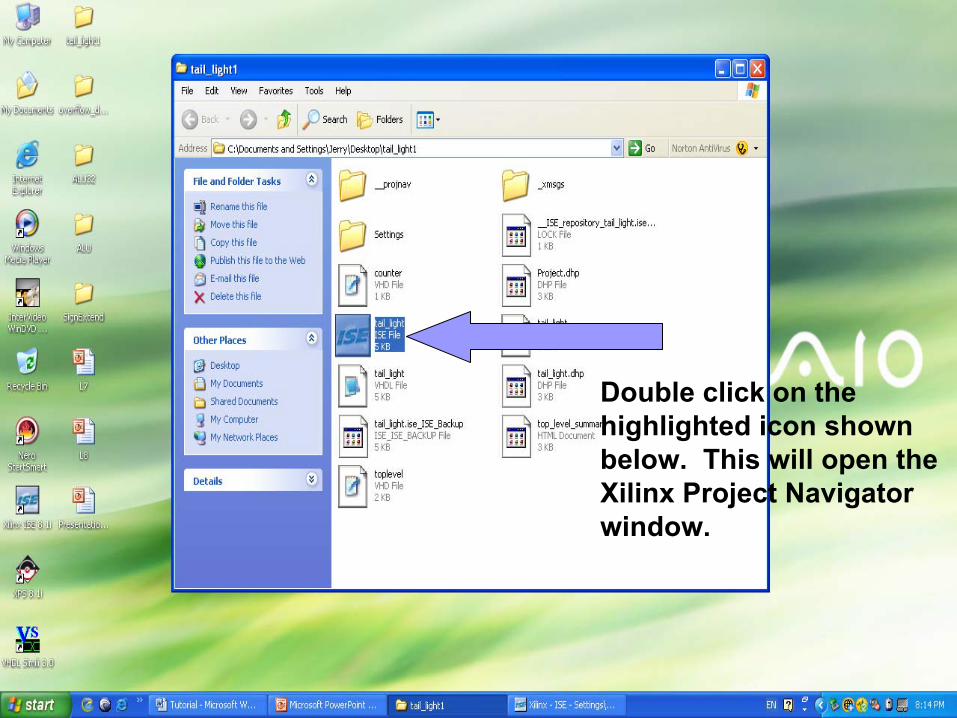
Double click on the highlighted icon shown below. This will open the Xilinx Project Navigator window.

Create a new workspace by clicking File --New Project. The New Project will be called tail_light.
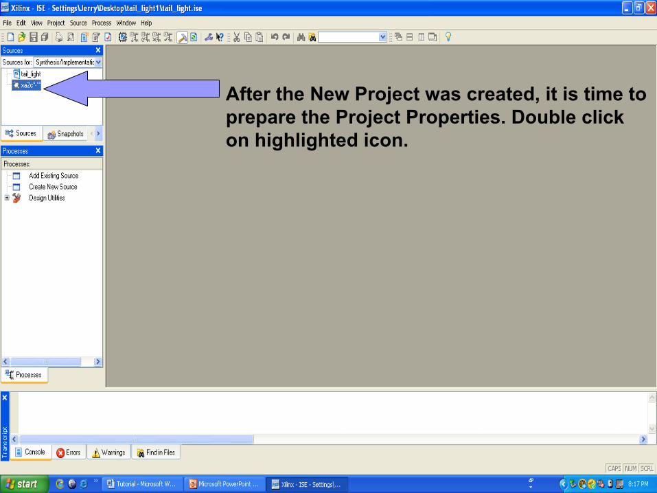
After the New Project was created, it is time to prepare the Project Properties. Double click on highlighted icon.

It will open a new window called Project Properties.
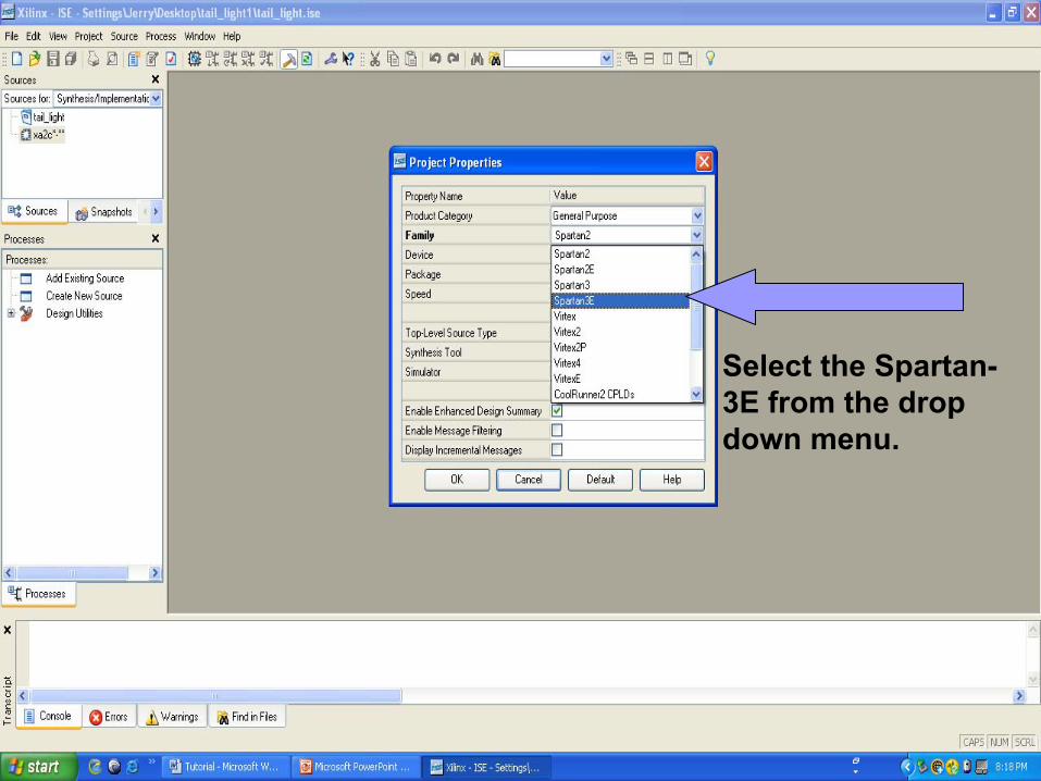
Select the Spartan-3E from the drop down menu.

For the Device select (XC3S350E)

For the Package select (FG320)

For the Speed use the default -5.


As you can see, the Device changed to xc3s350; otherwise, the user will not be able to assign pins.

Double click on Add Existing Source

It will open the Add Existing Sources Window. Select the file “counter” and than click OPEN. This procedure should also be performed for the tail_light file and for the top_level file.


As you can see we added these three files

If you want to display the vhdl code, double click here so the three different files will be available. The user can write new code or make changes to the existing code.

Expand the User Constraintsin the Processes for Sourcewindow and double click Assign Package Pins. This is where you tell Xilinx which pins on the Spartan-3E will be used.
The Processes of Sourcewindow shows the different process that can be done to the selected code. Here the user can compile the source code, generate synthesis reports, generate a file for download into the FPGA, and download a file to an FPGA.

Double click on Assign Package Pins

In the Design Object List I/O Pins window type in the following pin assignments under the heading Loc.
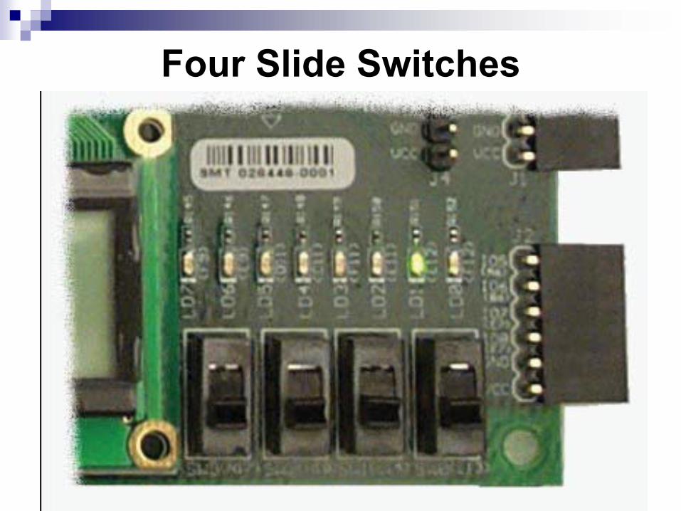
Four Slide Switches
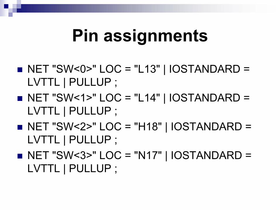
Pin assignments
NET "SW<0>" LOC = "L13" | IOSTANDARD = LVTTL | PULLUP ;NET "SW<1>" LOC = "L14" | IOSTANDARD = LVTTL | PULLUP ;NET "SW<2>" LOC = "H18" | IOSTANDARD = LVTTL | PULLUP ;NET "SW<3>" LOC = "N17" | IOSTANDARD = LVTTL | PULLUP ;


Eight Discrete LEDs

UCF Constraints for Eight Discrete LEDs
NET "LED<7>" LOC = "F9" | IOSTANDARD = LVTTL | SLEW = SLOW | DRIVE = 8 ;NET "LED<6>" LOC = "E9" | IOSTANDARD = LVTTL | SLEW = SLOW | DRIVE = 8 ;NET "LED<5>" LOC = "D11" | IOSTANDARD = LVTTL | SLEW = SLOW | DRIVE = 8 ;NET "LED<4>" LOC = "C11" | IOSTANDARD = LVTTL | SLEW = SLOW | DRIVE = 8 ;NET "LED<3>" LOC = "F11" | IOSTANDARD = LVTTL | SLEW = SLOW | DRIVE = 8 ;NET "LED<2>" LOC = "E11" | IOSTANDARD = LVTTL | SLEW = SLOW | DRIVE = 8 ;NET "LED<1>" LOC = "E12" | IOSTANDARD = LVTTL | SLEW = SLOW | DRIVE = 8 ;NET "LED<0>" LOC = "F12" | IOSTANDARD = LVTTL | SLEW = SLOW | DRIVE = 8 ;


This action will create a .ucf file for the top_level-struct file and will contain the pin assignments for the Spartan-3E.

Make sure that top_level-struct is selected in the Sources window.
In the Processes window, expand the Synthesize-XST process and then double click it. This action will check the syntax of the source code for top_level-struct and convert the source code into a netlist of gates. A synthesis report will also be produced. When the synthesis is finished, green check marks should be displayed just like in the next slide indicating that top_level-struct has compiled successfully.


Expand the Implement Design process and double click on it. This is where the netlist is translated, mapped, placed and routed for the logic circuits of the Spartan-3E FPGA.

After this process has been run, green check marks should be displayed

Expand the Generate Programming Fileprocess and double click on it.

This process creates a bit file that is used to program the Spartan-3E chip. Again, after this process is finished, green check marks should be shown.

FPGA
Now you are ready to program the Spartan-3E chip. Plug-in the USB cable to the computer. Connect the FPGA Spartan-3E board to power FIRST, then connect the USB cable to the board. This order must be followed for the Spartan-3E chip to be programmed properly.


POWER is ON


The system will automatically install the driver. If the driver is installed correctly, the green light should be displayed

Now double click on Configure Device (iMPACT) under the Generate Programming Fileprocess.

You will be asked how you want the device configured. Select Boundary Scan Modeand click Finish.
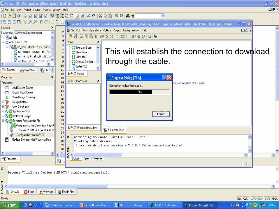
This will establish the connection to download through the cable.


Open the top_level.bit file.

Should a warning appear declaring that the Startup Clock has been changed to the jtagclk, disregard the warning and click OK


Right click on the depiction of the Spartan-3E chip and select Program


If the download was successful, the message “Program Succeeded” will be displayed.


FPGA Demo