Embed Size (px)
Citation preview
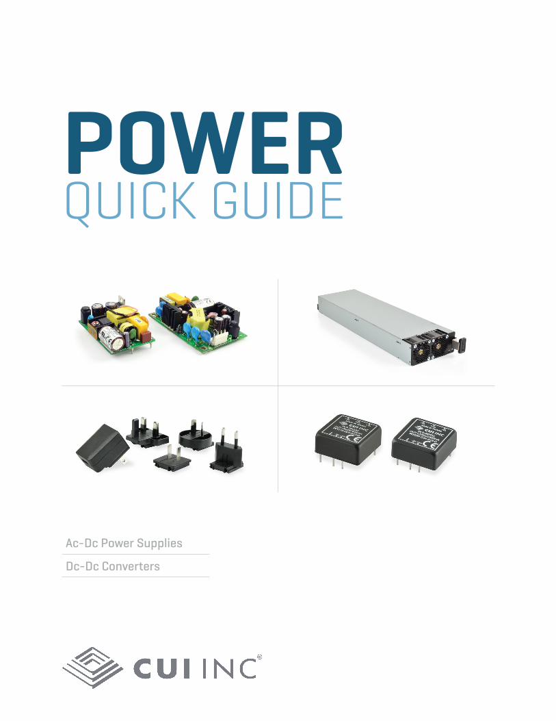
POWER QUICK GUIDE
Ac-Dc Power Supplies
Dc-Dc Converters
As a leader in the power supply industry, we realize that power is playing an increasingly critical role in your designs. We also know it can be difficult to stay current on the latest power trends and regulations. To keep you one step ahead, we seek to integrate cutting-edge technologies and design techniques in our ac-dc and dc-dc power modules. Our mission is to support you from start to finish, collaborating to ensure your next project is a success.
Focusing on EfficiencyEvery watt of power consumption matters in today’s electronic designs. From skyrocketing power density requirements in next generation networking equipment to uncertainty surrounding the latest global regulations impacting external power supplies, power is no longer an afterthought in the design process. To help you address your power challenges, we've set out to push the energy efficiency initiative across our entire power portfolio. This can be seen in our Novum® Advanced Power modules that are on the leading edge of the efficiency and power density curve, and in our range of open frame ac-dc power supplies that seek to reduce stand-by power consumption to a minimum. Additionally, we are continually monitoring the latest energy efficiency regulations, ensuring that our products are in compliance and you stay informed and up-to-date.
Supporting InnovationAt CUI we want to do everything we can to make your next project a success. That’s why we've developed a set of online tools to help accelerate your design efforts, including a robust parametric search, fully qualified 3D models, and a comprehensive library of educational videos, white papers, and application notes. Of course, CUI’s technical support team, and those of our representatives, are always available to help too. We never forget that our success depends on yours.
Your power expert.

Table of ContentsAc-Dc Power Supplies Dc-Dc Converters
Front-End 4~5 Novum® Intermediate Bus Converters 17
Board Mount 6~7 Novum® Digital POL Modules 18
Chassis Mount 8~12 Isolated Board Mount 19~23
External 13~15 Isolated Chassis Mount 24~25
Ac LED Drivers 15 Isolated DIN-Rail 26
DIN-Rail 16 Dc LED Drivers 27
Non-Isolated 28
Industry Expertise Our diverse portfolio of power products addresses design challenges across a range of applications and markets, from our front-end ac-dc power supplies and digital point-of-load modules which support leading power densities in the telecom space, to our high efficiency medical power supplies that enable greater portability in home healthcare equipment. Here are some of the major industries that we serve:
Quality MattersAs an ISO 9001:2008 company, we are committed to establishing, implementing, maintaining, and improving the processes necessary to consistently meet customer, statutory, and regulatory requirements. Understanding that failure is not an option for many of our customers, we start with an exhaustive product qualification process for all power supplies that we release to the market, supported by a robust manufacturing management program. As additional support, we are able to offer in-house failure analysis as well as on the ground quality engineering support in Asia.
∆ Networking ∆ Medical
∆ Consumer Electronics ∆ Renewable Energy
∆ Industrial ∆ Lighting
∆ Robotics ∆ Transport
4 | Power Quick Guide
Front-End
Serie
s
Pow
er (W
)
Inpu
t Ran
ge
Outp
ut V
olta
ge (V
dc)
Effici
ency
Size
L x
W x
H in
.(m
m)
Hot
Sw
ap
Load
Sha
re
I2 C D
igita
l Int
erfa
ce
N+
1 Re
dund
ancy
Plat
inum
Effi
cien
cy
PSE-600-48 600 90 ~ 264 Vac 48 90% 10 x 3.3 x 1.6 (254 x 83.8 x 40.6) Δ Δ Δ ΔPSE-800-48 800 90 ~ 264 Vac 48 90% 10 x 3.3 x 1.6 (254 x 83.8 x 40.6) Δ Δ Δ ΔPSE-850-12 850 90 ~ 264 Vac 12 89% 10 x 3.3 x 1.6 (254 x 83.8 x 40.6) Δ Δ Δ ΔPSE-1000-54 1000 90 ~ 264 Vac 54 90% 10 x 3.3 x 1.6 (254 x 83.8 x 40.6) Δ Δ Δ ΔPSA-1100-12 1100 90 ~ 264 Vac 12 93.5% 12.7 x 2.2 x 1.6 (321.5 x 54.5 x 40) Δ Δ Δ ΔPSD-1100-12 1100 40 ~ 72 Vdc 12 93.5% 12.7 x 2.2 x 1.6 (321.5 x 54.5 x 40) Δ Δ Δ Δ Δ
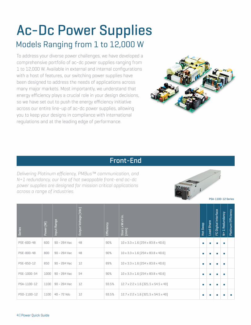
Ac-Dc Power Supplies Models Ranging from 1 to 12,000 W To address your diverse power challenges, we have developed a comprehensive portfolio of ac-dc power supplies ranging from 1 to 12,000 W. Available in external and internal configurations with a host of features, our switching power supplies have been designed to address the needs of applications across many major markets. Most importantly, we understand that energy efficiency plays a crucial role in your design decisions, so we have set out to push the energy efficiency initiative across our entire line-up of ac-dc power supplies, allowing you to keep your designs in compliance with international regulations and at the leading edge of performance.
Front-End
Delivering Platinum efficiency, PMBus™ communication, and N+1 redundancy, our line of hot swappable front-end ac-dc power supplies are designed for mission critical applications across a range of industries.
PSA-1100-12 Series
Ac-Dc Power Supplies
Power Quick Guide | 5
Accessories 1U Power ShelvesSeries Airflow Direction Shelf Power at 110 Vin Shelf Power at 220 Vin Output IEC Inlet Type
PPR-1U Front to Back 6000 W 12000 W All Parallel, Dual Polarity Terminal Block C22
PPR-1U-A Front to Back 6000 W (3 kW + 3 kW) 12000 W (6 kW + 6 kW) A & B Feed, Dual Polarity Terminal Block C22
PPR-1U-B Back to Front 5400 W 12000 W All Parallel, Dual Polarity Terminal Block C20
PPR-1U-C Back to Front 5400 W (2.7 kW + 2.7 kW) 12000 W (6 kW + 6 kW) A & B Feed, Dual Polarity Terminal Block C20
PPR-1U-D Front to Back 6000 W 12000 W All Parallel, Single Polarity Terminal Block C22
PPR-1U-E Back to Front 5400 W 12000 W A & B Feed, Single Polarity Terminal Block C20
Front-End
Serie
s
Pow
er (W
)
Inpu
t Ran
ge
Outp
ut V
olta
ge (V
dc)
Effici
ency
Size
L x
W x
H in
.(m
m)
Hot
Sw
ap
Load
Sha
re
I2 C D
igita
l Int
erfa
ce
N+
1 Re
dund
ancy
Plat
inum
Effi
cien
cy
PSE-1200-12 1200 90 ~ 264 Vac 12 90% 10 x 4 x 1.6 (254 x 102.4 x 40.6) Δ Δ Δ ΔPSE-1800-48 1800 90 ~ 264 Vac 48 91% 11 x 4 x 1.6 (279.4 x 101.6 x 40.6) Δ Δ Δ ΔPFR-2100 2050 180 ~ 264 Vac 100~410 93% 11.5 x 5.2 x 2.5 (292.1 x 132.1 x 63.5) Δ Δ ΔPSE-3000-48 3000 90 ~ 264 Vac 48 (42~55) 94% 14 x 4 x 1.6 (335.6 x 101.6 x 40.6) Δ Δ Δ Δ ΔPSE-3000-54 3000 90 ~ 264 Vac 54 (42~55) 94% 14 x 4 x 1.6 (335.6 x 101.6 x 40.6) Δ Δ Δ Δ Δ
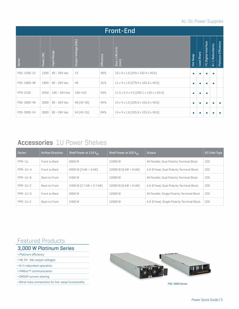
Featured Products3,000 W Platinum Series∆ Platinum efficiency
∆ 48, 54 Vdc output voltages
∆ N+1 redundant operation
∆ PMBus™ communication
∆ DROOP current sharing
∆ Blind mate connections for hot-swap functionality PSE-3000 Series
Ac-Dc Power Supplies
6 | Power Quick Guide
Board Mount
Serie
s
Pow
er (W
)
Inpu
t Vol
tage
(Vac
)
Outp
ut V
olta
ge (V
dc)
Effici
ency
Size
L x
W x
H in
.(m
m)
Open
Fra
me
Met
al C
ase
U-f
ram
e
Enca
psul
ated
Mod
ule
Load
Sha
re
Med
ical
On/O
ff C
ontr
ol
PFC
PBK-1 1 85~264 5, 9, 12, 15, 24 70% 1.38 x 0.43 x 0.98 (35.00 x 11.00 x 25.00) ∫
PBK-1-B 1 85~264 5, 9, 12, 15, 24 70% 1.38 x 0.98 x 0.43 (35.00 x 25.00 x 11.00) ∫
PBO-1 1 85~264 5, 9, 12, 15, 24 70% 1.38 x 0.43 x 0.71 (35.00 x 11.00 x 18.00) ∫
VSK-S1 1 85~305 3.3, 5, 9, 12, 15, 24 75% 1.33 x 0.87 x 0.71 (33.78 x 22.10 x 18.03) ∫
VSK-S2 2 85~305 3.3, 5, 9, 12, 15, 24 78% 1.33 x 0.87 x 0.71 (33.78 x 22.10 x 18.03) ∫
PBK-3 3 85~264 3.3, 5, 9, 12, 15, 24 78% 1.45 x 0.43 x 0.98 (37.00 x 11.00 x 25.00) ∫
PBK-3-B 3 85~264 3.3, 5, 9, 12, 15, 24 78% 1.45 x 0.98 x 0.43 (37.00 x 25.00 x 11.00) ∫
PBO-3 3 85~264 3.3, 5, 9, 12, 15, 24 80% 1.38 x 0.43 x 0.71(35.00 x 11.00 x 18.00) ∫
PBO-3-B 3 85~264 3.3, 5, 9, 12, 15, 24 80% 1.38 x 0.71 x 0.43(35.00 x 18.00 x 11.00) ∫
VSK-S3 3 85~264 3.3, 5, 9, 12, 15, 24 78% 1.46 x 0.91 x 0.59 (37.08 x 23.11 x 14.98) ∫
PBK-5 5 85~264 3.3, 5, 9, 12, 15, 24 75% 1.65 x 0.43 x 0.95 (42.00 x 11.00 x 24.00) ∫
PBK-5-B 5 85~264 3.3, 5, 9, 12, 15, 24 75% 1.65 x 0.95 x 0.43 (42.00 x 24.00 x 11.00) ∫
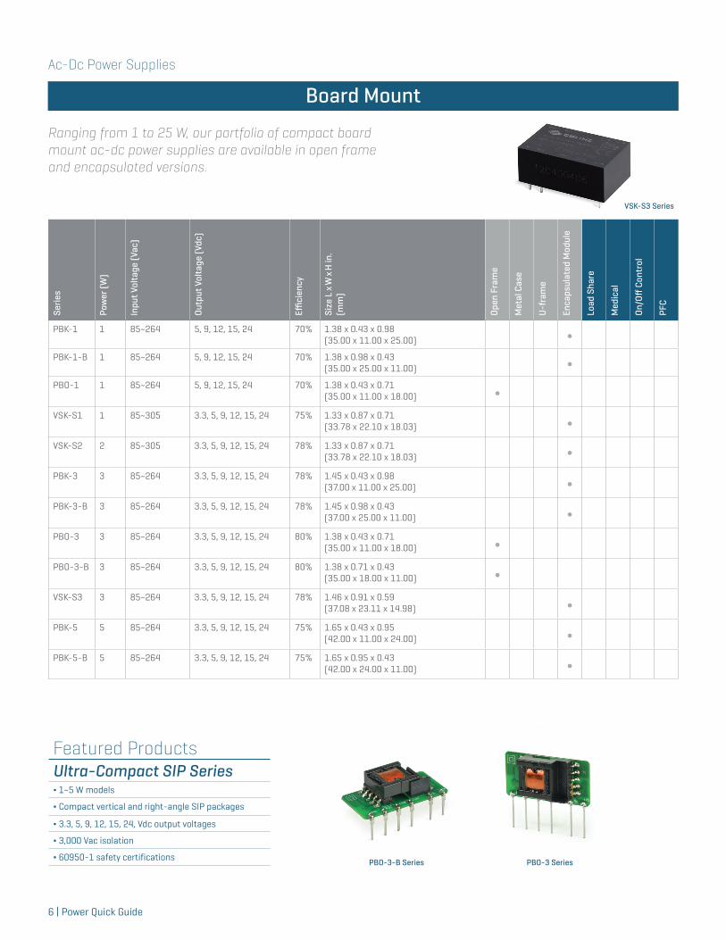
Ranging from 1 to 25 W, our portfolio of compact board mount ac-dc power supplies are available in open frame and encapsulated versions.
Board Mount
Featured ProductsUltra-Compact SIP Series∆ 1~5 W models
∆ Compact vertical and right-angle SIP packages
∆ 3.3, 5, 9, 12, 15, 24, Vdc output voltages
∆ 3,000 Vac isolation
∆ 60950-1 safety certifications
VSK-S3 Series
PBO-3 SeriesPBO-3-B Series
Ac-Dc Power Supplies
Power Quick Guide | 7
Board Mount
Serie
s
Pow
er (W
)
Inpu
t Vol
tage
(Vac
)
Outp
ut V
olta
ge (V
dc)
Effici
ency
Size
L x
W x
H in
.(m
m)
Open
Fra
me
Met
al C
ase
U-f
ram
e
Enca
psul
ated
Mod
ule
Load
Sha
re
Med
ical
On/O
ff C
ontr
ol
PFC
PBO-5 5 85~264 3.3, 5, 9, 12, 15, 24 79% 1.65 x 0.54 x 0.79 (42.00 x 13.65 x 20.00) ∫
PBO-5-B 5 85~264 3.3, 5, 9, 12, 15, 24 79% 1.65 x 0.79 x 0.54 (42.00 x 20.00 x 13.65) ∫
VSK-S5 5 85~264 3.3, 5, 9, 12, 15, 24 83% 2.00 x 1.00 x 0.60 (50.80 x 25.40 x 15.20) ∫
VOF-6 6 85~264 3.3, 5, 12, 15, 24 80% 2.17 x 1.38 x 0.65 (55.12 x 35.05 x 16.51) ∫
VSK-S10 10 85~264 3.3, 5, 9, 12, 15, 24 83% 2.10 x 1.12 x 0.75 (53.50 x 28.50 x 19.00) ∫
VOF-10 10 85~264 3.3, 5, 12, 15, 24 78% 2.56 x 1.77 x 0.91 (65.02 x 44.96 x 23.11) ∫
VOF-15 15 85~264 3.3, 5, 12, 15, 24, 48 83% 2.75 x 1.89 x 0.91 (69.85 x 48.00 x 23.11) ∫
VSK-S15 15 85~264 3.3, 5, 9, 12, 15, 24, 48 85% 2.44 x 1.77 x 0.89 (61.98 x 44.96 x 22.60) ∫
VSK-S20 20 85~264 3.3, 5, 9, 12, 15, 24 85% 2.76 x 1.89 x 0.93 (70.10 x 48.00 x 23.62) ∫
VMS-20 20 85~264 3.3, 5, 12, 15, 24 85% 2.38 x 1.60 x 0.67 (60.45 x 40.60 x 17.01)
∫ +
VSK-S25 25 85~264 5, 9, 12, 15, 24, 48 87% 2.76 x 1.89 x 0.93 (70.10 x 48.00 x 23.62)
∫
VBM-100 100 90~264 12, 24, 28, 36, 48 92% 4.60 x 2.40 x 0.70 (116.80 x 61.00 x 17.00)
∫ Δ
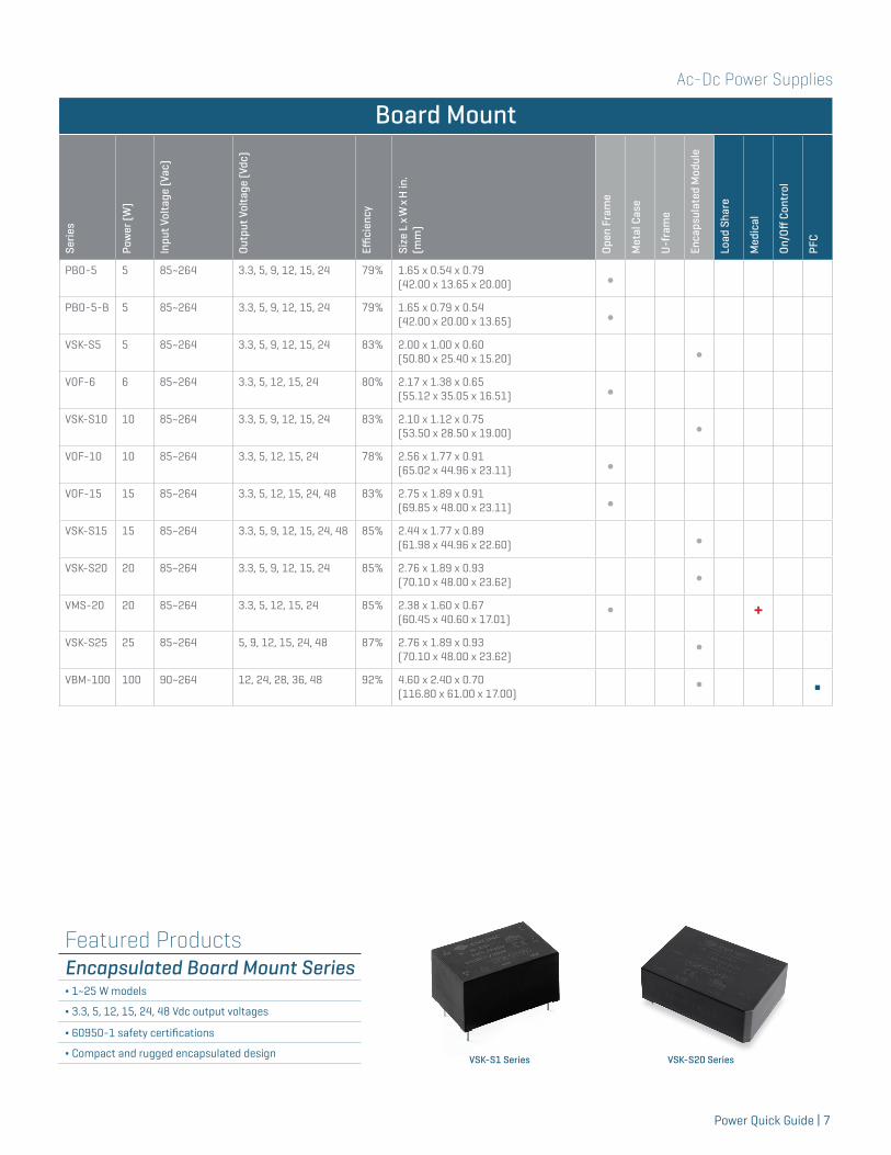
Featured ProductsEncapsulated Board Mount Series∆ 1~25 W models
∆ 3.3, 5, 12, 15, 24, 48 Vdc output voltages
∆ 60950-1 safety certifications
∆ Compact and rugged encapsulated design VSK-S20 SeriesVSK-S1 Series
Ac-Dc Power Supplies
8 | Power Quick Guide
Chassis Mount
Serie
s
Pow
er (W
)
Inpu
t Ran
ge (V
ac)
Outp
ut V
olta
ge (V
dc)
Effici
ency
Size
L x
W x
H in
.(m
m)
Open
Fra
me
Met
al C
ase
U-f
ram
e
Enca
psul
ated
Mod
ule
Load
Sha
re
Med
ical
On/O
ff C
ontr
ol
PFC
VSK-S5-T 5 85~264 3.3, 5, 9, 12, 15, 24 83% 3.78 x 2.13 x 1.08 (96.10 x 54.00 x 27.50) ∫
VSK-S10-T 10 85~264 3.3, 5, 9, 12, 15, 24 83% 3.78 x 2.13 x 1.08 (96.10 x 54.00 x 27.50) ∫
VSK-S15-T 15 85~264 3.3, 5, 9, 12, 15, 24, 48 85% 3.78 x 2.13 x 1.22 (96.01 x 54.10 x 30.98) ∫
VSK-S20-T 20 85~264 3.3, 5, 9, 12, 15, 24 85% 3.78 x 2.13 x 1.26(96.01 x 54.10 x 32.00) ∫
VSK-S25-T 25 85~264 5, 9, 12, 15, 24, 48 87% 3.78 x 2.13 x 1.26(96.01 x 54.10 x 32.00) ∫
VGS-25 25 88~264 3.3, 5, 12, 15, 24, 48 88% 3.09 x 2.00 x 1.11(78.49 x 50.01 x 28.19) ∫
VOF-30 30 90~277 5, 12, 15, 18, 24 86% 3.54 x 2.00 x 0.83(90.00 x 50.80 x 21.10) ∫
VGD-30 30 85~264 5/12, 5/24 80% 3.90 x 3.80 x 1.40(99.06 x 95.52 x 35.56) ∫
VMS-40 40 85~264 3.3, 5, 9, 12, 15, 24, 30, 36, 48 88% 3.00 x 2.00 x 0.75(76.20 x 50.01 x 19.00) ∫ +
VFM40 40 90~264 3.3/5/-12, 5/12, 5/24, 5/12/-5, 5/±12, 5/±15, 5/24/-12, 5/24/-5, 5/24/12
78% 4.00 x 2.00 x 1.06 (101.60 x 50.01 x 26.92) ∫
VOF-50 50 90~277 5, 12, 15, 24 89% 4.00 x 2.00 x 1.32(101.60 x 50.75 x 33.60) ∫
VGS-50 50 88~264 3.3, 5, 12, 15, 24, 48 90% 3.90 x 3.20 x 1.40(99.06 x 81.28 x 35.50) ∫
VMS-60 60 88~264 5, 12, 15, 24, 48 90% 4.00 x 2.00 x 1.10(101.60 x 50.01 x 27.90) ∫ +
VGD-60 60 85~264 5/12, 5/24 80% 5.10 x 3.90 x 1.50(129.54 x 99.06 x 38.10) ∫
VOF-70 70 90~277 5, 12, 15, 24, 28, 48 90% 4.00 x 2.00 x 1.32(101.60 x 50.75 x 33.60) ∫
VGS-75 75 88~264 3.3, 5, 12, 15, 24, 48 90% 5.10 x 3.84 x 1.48(129.54 x 97.54 x 37.59) ∫
PSF-75 75 90~264 13.8/13.8, 13.8/13.8/5, 27.6/27.6, 27.6/27.6/5
88% 4.84 x 3.74 x 1.22(123.00 x 95.00 x 31.00) ∫
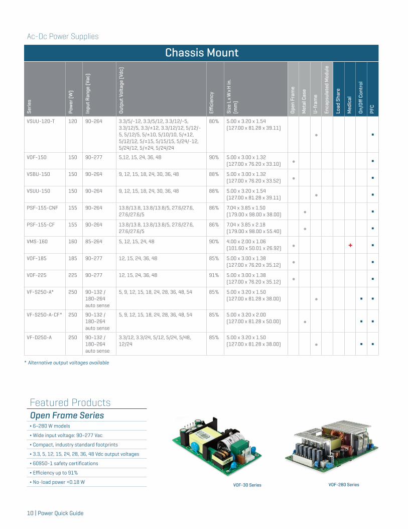
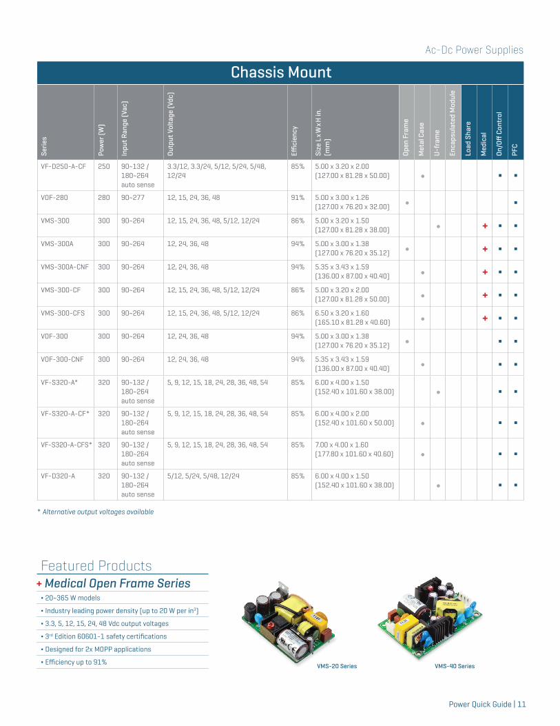
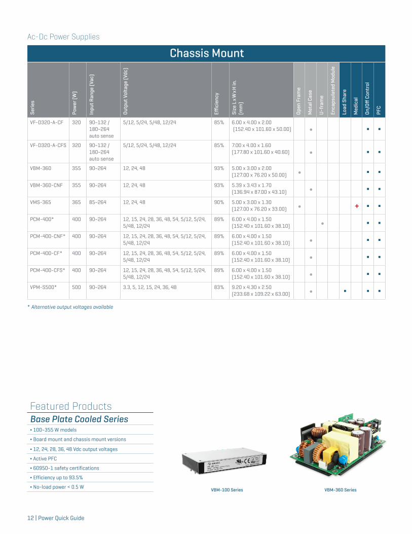
Chassis Mount
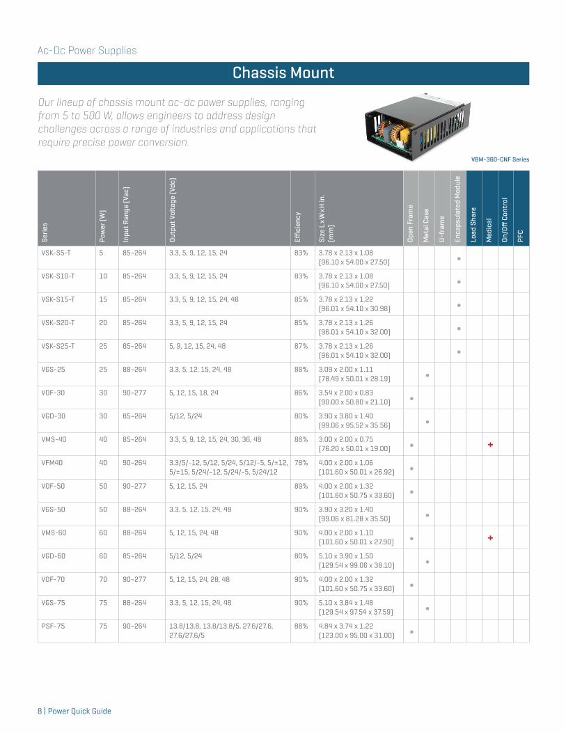
Our lineup of chassis mount ac-dc power supplies, ranging from 5 to 500 W, allows engineers to address design challenges across a range of industries and applications that require precise power conversion.
VBM-360-CNF Series
Ac-Dc Power Supplies
Power Quick Guide | 9
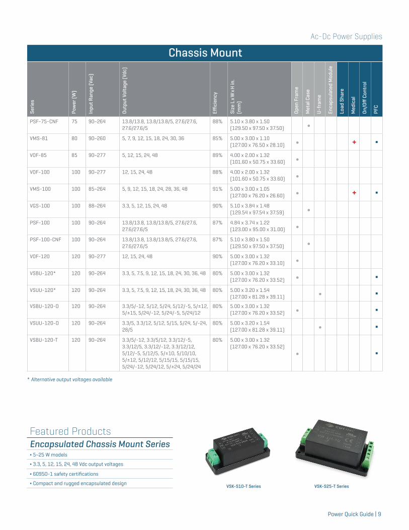
Featured ProductsEncapsulated Chassis Mount Series∆ 5~25 W models
∆ 3.3, 5, 12, 15, 24, 48 Vdc output voltages
∆ 60950-1 safety certifications
∆ Compact and rugged encapsulated design VSK-S10-T Series VSK-S25-T Series
Chassis Mount
Serie
s
Pow
er (W
)
Inpu
t Ran
ge (V
ac)
Outp
ut V
olta
ge (V
dc)
Effici
ency
Size
L x
W x
H in
.(m
m)
Open
Fra
me
Met
al C
ase
U-f
ram
e
Enca
psul
ated
Mod
ule
Load
Sha
re
Med
ical
On/O
ff C
ontr
ol
PFC
PSF-75-CNF 75 90~264 13.8/13.8, 13.8/13.8/5, 27.6/27.6, 27.6/27.6/5
88% 5.10 x 3.80 x 1.50(129.50 x 97.50 x 37.50) ∫
VMS-81 80 90~260 5, 7, 9, 12, 15, 18, 24, 30, 36 85% 5.00 x 3.00 x 1.10(127.00 x 76.50 x 28.10) ∫ + Δ
VOF-85 85 90~277 5, 12, 15, 24, 48 89% 4.00 x 2.00 x 1.32(101.60 x 50.75 x 33.60) ∫
VOF-100 100 90~277 12, 15, 24, 48 88% 4.00 x 2.00 x 1.32(101.60 x 50.75 x 33.60) ∫
VMS-100 100 85~264 5, 9, 12, 15, 18, 24, 28, 36, 48 91% 5.00 x 3.00 x 1.05(127.00 x 76.20 x 26.60) ∫ + Δ
VGS-100 100 88~264 3.3, 5, 12, 15, 24, 48 90% 5.10 x 3.84 x 1.48(129.54 x 97.54 x 37.59) ∫
PSF-100 100 90~264 13.8/13.8, 13.8/13.8/5, 27.6/27.6, 27.6/27.6/5
87% 4.84 x 3.74 x 1.22(123.00 x 95.00 x 31.00) ∫
PSF-100-CNF 100 90~264 13.8/13.8, 13.8/13.8/5, 27.6/27.6, 27.6/27.6/5
87% 5.10 x 3.80 x 1.50(129.50 x 97.50 x 37.50) ∫
VOF-120 120 90~277 12, 15, 24, 48 90% 5.00 x 3.00 x 1.32(127.00 x 76.20 x 33.10) ∫
VSBU-120* 120 90~264 3.3, 5, 7.5, 9, 12, 15, 18, 24, 30, 36, 48 80% 5.00 x 3.00 x 1.32(127.00 x 76.20 x 33.52) ∫ Δ
VSUU-120* 120 90~264 3.3, 5, 7.5, 9, 12, 15, 18, 24, 30, 36, 48 80% 5.00 x 3.20 x 1.54(127.00 x 81.28 x 39.11) ∫ Δ
VSBU-120-D 120 90~264 3.3/5/-12, 5/12, 5/24, 5/12/-5, 5/±12, 5/±15, 5/24/-12, 5/24/-5, 5/24/12
80% 5.00 x 3.00 x 1.32(127.00 x 76.20 x 33.52) ∫ Δ
VSUU-120-D 120 90~264 3.3/5, 3.3/12, 5/12, 5/15, 5/24, 5/-24, 28/5
80% 5.00 x 3.20 x 1.54 (127.00 x 81.28 x 39.11) ∫ Δ
VSBU-120-T 120 90~264 3.3/5/-12, 3.3/5/12, 3.3/12/-5, 3.3/12/5, 3.3/12/-12, 3.3/12/12, 5/12/-5, 5/12/5, 5/±10, 5/10/10, 5/±12, 5/12/12, 5/15/15, 5/15/15, 5/24/-12, 5/24/12, 5/±24, 5/24/24
80% 5.00 x 3.00 x 1.32(127.00 x 76.20 x 33.52)
∫ Δ
* Alternative output voltages available
Ac-Dc Power Supplies
10 | Power Quick Guide
Chassis Mount
Serie
s
Pow
er (W
)
Inpu
t Ran
ge (V
ac)
Outp
ut V
olta
ge (V
dc)
Effici
ency
Size
L x
W x
H in
.(m
m)
Open
Fra
me
Met
al C
ase
U-f
ram
e
Enca
psul
ated
Mod
ule
Load
Sha
re
Med
ical
On/O
ff C
ontr
ol
PFC
VSUU-120-T 120 90~264 3.3/5/-12, 3.3/5/12, 3.3/12/-5, 3.3/12/5, 3.3/±12, 3.3/12/12, 5/12/-5, 5/12/5, 5/±10, 5/10/10, 5/±12, 5/12/12, 5/±15, 5/15/15, 5/24/-12, 5/24/12, 5/±24, 5/24/24
80% 5.00 x 3.20 x 1.54(127.00 x 81.28 x 39.11)
∫ Δ
VOF-150 150 90~277 5,12, 15, 24, 36, 48 90% 5.00 x 3.00 x 1.32(127.00 x 76.20 x 33.10) ∫ Δ
VSBU-150 150 90~264 9, 12, 15, 18, 24, 30, 36, 48 88% 5.00 x 3.00 x 1.32(127.00 x 76.20 x 33.52) ∫ Δ
VSUU-150 150 90~264 9, 12, 15, 18, 24, 30, 36, 48 88% 5.00 x 3.20 x 1.54(127.00 x 81.28 x 39.11) ∫ Δ
PSF-155-CNF 155 90~264 13.8/13.8, 13.8/13.8/5, 27.6/27.6, 27.6/27.6/5
86% 7.04 x 3.85 x 1.50 (179.00 x 98.00 x 38.00) ∫ Δ
PSF-155-CF 155 90~264 13.8/13.8, 13.8/13.8/5, 27.6/27.6, 27.6/27.6/5
86% 7.04 x 3.85 x 2.18 (179.00 x 98.00 x 55.40) ∫ Δ
VMS-160 160 85~264 5, 12, 15, 24, 48 90% 4.00 x 2.00 x 1.06 (101.60 x 50.01 x 26.92) ∫ + Δ
VOF-185 185 90~277 12, 15, 24, 36, 48 85% 5.00 x 3.00 x 1.38(127.00 x 76.20 x 35.12) ∫ Δ
VOF-225 225 90~277 12, 15, 24, 36, 48 91% 5.00 x 3.00 x 1.38(127.00 x 76.20 x 35.12) ∫ Δ
VF-S250-A* 250 90~132 / 180~264 auto sense
5, 9, 12, 15, 18, 24, 28, 36, 48, 54 85% 5.00 x 3.20 x 1.50 (127.00 x 81.28 x 38.00) ∫ Δ Δ
VF-S250-A-CF* 250 90~132 / 180~264 auto sense
5, 9, 12, 15, 18, 24, 28, 36, 48, 54 85% 5.00 x 3.20 x 2.00 (127.00 x 81.28 x 50.00) ∫ Δ Δ
VF-D250-A 250 90~132 / 180~264 auto sense
3.3/12, 3.3/24, 5/12, 5/24, 5/48, 12/24
85% 5.00 x 3.20 x 1.50 (127.00 x 81.28 x 38.00) ∫ Δ Δ
Featured ProductsOpen Frame Series∆ 6~280 W models
∆ Wide input voltage: 90~277 Vac
∆ Compact, industry standard footprints
∆ 3.3, 5, 12, 15, 24, 28, 36, 48 Vdc output voltages
∆ 60950-1 safety certifications
∆ Efficiency up to 91%
∆ No-load power <0.18 W VOF-30 Series VOF-280 Series
* Alternative output voltages available
Ac-Dc Power Supplies
Power Quick Guide | 11
Chassis Mount
Serie
s
Pow
er (W
)
Inpu
t Ran
ge (V
ac)
Outp
ut V
olta
ge (V
dc)
Effici
ency
Size
L x
W x
H in
.(m
m)
Open
Fra
me
Met
al C
ase
U-f
ram
e
Enca
psul
ated
Mod
ule
Load
Sha
re
Med
ical
On/O
ff C
ontr
ol
PFC
VF-D250-A-CF 250 90~132 / 180~264 auto sense
3.3/12, 3.3/24, 5/12, 5/24, 5/48, 12/24
85% 5.00 x 3.20 x 2.00 (127.00 x 81.28 x 50.00) ∫ Δ Δ
VOF-280 280 90~277 12, 15, 24, 36, 48 91% 5.00 x 3.00 x 1.26(127.00 x 76.20 x 32.00) ∫ Δ
VMS-300 300 90~264 12, 15, 24, 36, 48, 5/12, 12/24 86% 5.00 x 3.20 x 1.50 (127.00 x 81.28 x 38.00) ∫ + Δ Δ
VMS-300A 300 90~264 12, 24, 36, 48 94% 5.00 x 3.00 x 1.38(127.00 x 76.20 x 35.12) ∫ + Δ Δ
VMS-300A-CNF 300 90~264 12, 24, 36, 48 94% 5.35 x 3.43 x 1.59(136.00 x 87.00 x 40.40) ∫ + Δ Δ
VMS-300-CF 300 90~264 12, 15, 24, 36, 48, 5/12, 12/24 86% 5.00 x 3.20 x 2.00 (127.00 x 81.28 x 50.00) ∫ + Δ Δ
VMS-300-CFS 300 90~264 12, 15, 24, 36, 48, 5/12, 12/24 86% 6.50 x 3.20 x 1.60 (165.10 x 81.28 x 40.60) ∫ + Δ Δ
VOF-300 300 90~264 12, 24, 36, 48 94% 5.00 x 3.00 x 1.38(127.00 x 76.20 x 35.12) ∫ Δ Δ
VOF-300-CNF 300 90~264 12, 24, 36, 48 94% 5.35 x 3.43 x 1.59(136.00 x 87.00 x 40.40) ∫ Δ Δ
VF-S320-A* 320 90~132 / 180~264 auto sense
5, 9, 12, 15, 18, 24, 28, 36, 48, 54 85% 6.00 x 4.00 x 1.50 (152.40 x 101.60 x 38.00) ∫ Δ Δ
VF-S320-A-CF* 320 90~132 / 180~264 auto sense
5, 9, 12, 15, 18, 24, 28, 36, 48, 54 85% 6.00 x 4.00 x 2.00 (152.40 x 101.60 x 50.00) ∫ Δ Δ
VF-S320-A-CFS* 320 90~132 / 180~264 auto sense
5, 9, 12, 15, 18, 24, 28, 36, 48, 54 85% 7.00 x 4.00 x 1.60 (177.80 x 101.60 x 40.60) ∫ Δ Δ
VF-D320-A 320 90~132 / 180~264 auto sense
5/12, 5/24, 5/48, 12/24 85% 6.00 x 4.00 x 1.50 (152.40 x 101.60 x 38.00) ∫ Δ Δ
Featured Products + Medical Open Frame Series∆ 20~365 W models
∆ Industry leading power density (up to 20 W per in3)
∆ 3.3, 5, 12, 15, 24, 48 Vdc output voltages
∆ 3rd Edition 60601-1 safety certifications
∆ Designed for 2x MOPP applications
∆ Efficiency up to 91% VMS-20 Series VMS-40 Series
* Alternative output voltages available
Ac-Dc Power Supplies
12 | Power Quick Guide
Chassis Mount
Serie
s
Pow
er (W
)
Inpu
t Ran
ge (V
ac)
Outp
ut V
olta
ge (V
dc)
Effici
ency
Size
L x
W x
H in
.(m
m)
Open
Fra
me
Met
al C
ase
U-f
ram
e
Enca
psul
ated
Mod
ule
Load
Sha
re
Med
ical
On/O
ff C
ontr
ol
PFC
VF-D320-A-CF 320 90~132 / 180~264 auto sense
5/12, 5/24, 5/48, 12/24 85% 6.00 x 4.00 x 2.00 (152.40 x 101.60 x 50.00) ∫ Δ Δ
VF-D320-A-CFS 320 90~132 / 180~264 auto sense
5/12, 5/24, 5/48, 12/24 85% 7.00 x 4.00 x 1.60 (177.80 x 101.60 x 40.60) ∫ Δ Δ
VBM-360 355 90~264 12, 24, 48 93% 5.00 x 3.00 x 2.00 (127.00 x 76.20 x 50.00) ∫ Δ Δ
VBM-360-CNF 355 90~264 12, 24, 48 93% 5.39 x 3.43 x 1.70 (136.94 x 87.00 x 43.10) ∫ Δ Δ
VMS-365 365 85~264 12, 24, 48 90% 5.00 x 3.00 x 1.30 (127.00 x 76.20 x 33.00) ∫ + Δ Δ
PCM-400* 400 90~264 12, 15, 24, 28, 36, 48, 54, 5/12, 5/24, 5/48, 12/24
89% 6.00 x 4.00 x 1.50 (152.40 x 101.60 x 38.10) ∫ Δ Δ
PCM-400-CNF* 400 90~264 12, 15, 24, 28, 36, 48, 54, 5/12, 5/24, 5/48, 12/24
89% 6.00 x 4.00 x 1.50 (152.40 x 101.60 x 38.10) ∫ Δ Δ
PCM-400-CF* 400 90~264 12, 15, 24, 28, 36, 48, 54, 5/12, 5/24, 5/48, 12/24
89% 6.00 x 4.00 x 1.50 (152.40 x 101.60 x 38.10) ∫ Δ Δ
PCM-400-CFS* 400 90~264 12, 15, 24, 28, 36, 48, 54, 5/12, 5/24, 5/48, 12/24
89% 6.00 x 4.00 x 1.50 (152.40 x 101.60 x 38.10) ∫ Δ Δ
VPM-S500* 500 90~264 3.3, 5, 12, 15, 24, 36, 48 83% 9.20 x 4.30 x 2.50 (233.68 x 109.22 x 63.00) ∫ Δ Δ Δ
Featured ProductsBase Plate Cooled Series∆ 100~355 W models
∆ Board mount and chassis mount versions
∆ 12, 24, 28, 36, 48 Vdc output voltages
∆ Active PFC
∆ 60950-1 safety certifications
∆ Efficiency up to 93.5%
∆ No-load power < 0.5 W VBM-100 Series VBM-360 Series
* Alternative output voltages available
Ac-Dc Power Supplies
Power Quick Guide | 13
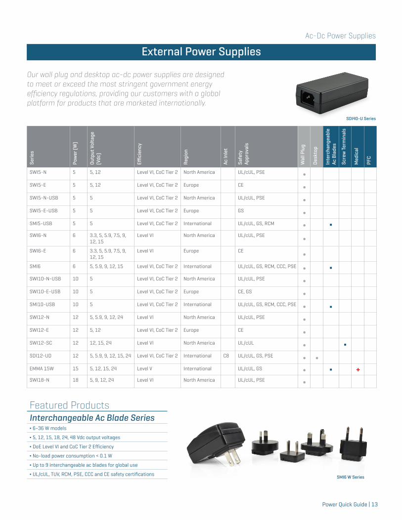
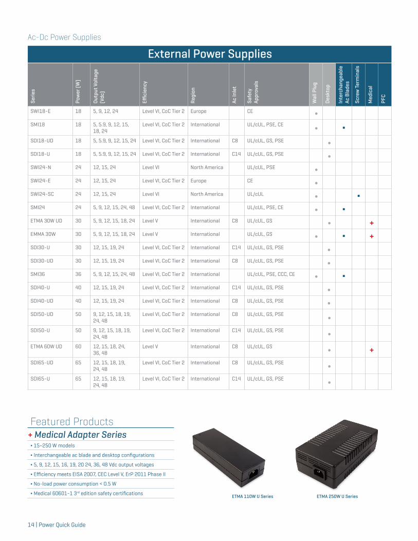
Featured ProductsInterchangeable Ac Blade Series∆ 6~36 W models
∆ 5, 12, 15, 18, 24, 48 Vdc output voltages
∆ DoE Level VI and CoC Tier 2 Efficiency
∆ No-load power consumption < 0.1 W
∆ Up to 9 interchangeable ac blades for global use
∆ UL/cUL, TUV, RCM, PSE, CCC and CE safety certifications
External Power Supplies
Serie
s
Pow
er (W
)
Outp
ut V
olta
ge
(Vdc
)
Effici
ency
Regi
on
Ac In
let
Safe
ty
Appr
oval
s
Wal
l Plu
g
Des
ktop
Inte
rcha
ngea
ble
Ac B
lade
s
Scre
w T
erm
inal
s
Med
ical
PFC
SWI5-N 5 5, 12 Level VI, CoC Tier 2 North America UL/cUL, PSE ∫SWI5-E 5 5, 12 Level VI, CoC Tier 2 Europe CE ∫SWI5-N-USB 5 5 Level VI, CoC Tier 2 North America UL/cUL, PSE ∫SWI5-E-USB 5 5 Level VI, CoC Tier 2 Europe GS ∫SMI5-USB 5 5 Level VI, CoC Tier 2 International UL/cUL, GS, RCM ∫ ΔSWI6-N 6 3.3, 5, 5.9, 7.5, 9,
12, 15Level VI North America UL/cUL, PSE ∫
SWI6-E 6 3.3, 5, 5.9, 7.5, 9, 12, 15
Level VI Europe CE ∫
SMI6 6 5, 5.9, 9, 12, 15 Level VI, CoC Tier 2 International UL/cUL, GS, RCM, CCC, PSE ∫ ΔSWI10-N-USB 10 5 Level VI, CoC Tier 2 North America UL/cUL, PSE ∫SWI10-E-USB 10 5 Level VI, CoC Tier 2 Europe CE, GS ∫SMI10-USB 10 5 Level VI, CoC Tier 2 International UL/cUL, GS, RCM, CCC, PSE ∫ ΔSWI12-N 12 5, 5.9, 9, 12, 24 Level VI North America UL/cUL, PSE ∫SWI12-E 12 5, 12 Level VI, CoC Tier 2 Europe CE ∫SWI12-SC 12 12, 15, 24 Level VI North America UL/cUL ∫ ΔSDI12-UD 12 5, 5.9, 9, 12, 15, 24 Level VI, CoC Tier 2 International C8 UL/cUL, GS, PSE ∫ ∫EMMA 15W 15 5, 12, 15, 24 Level V International UL/cUL, GS ∫ Δ +SWI18-N 18 5, 9, 12, 24 Level VI North America UL/cUL, PSE ∫
Our wall plug and desktop ac-dc power supplies are designed to meet or exceed the most stringent government energy efficiency regulations, providing our customers with a global platform for products that are marketed internationally.
External Power Supplies
ETMA 100W SeriesSDI40-U Series
SMI6 W Series
Ac-Dc Power Supplies
14 | Power Quick Guide
External Power Supplies
Serie
s
Pow
er (W
)
Outp
ut V
olta
ge
(Vdc
)
Effici
ency
Regi
on
Ac In
let
Safe
ty
Appr
oval
s
Wal
l Plu
g
Des
ktop
Inte
rcha
ngea
ble
Ac B
lade
s
Scre
w T
erm
inal
s
Med
ical
PFC
SWI18-E 18 5, 9, 12, 24 Level VI, CoC Tier 2 Europe CE ∫SMI18 18 5, 5.9, 9, 12, 15,
18, 24Level VI, CoC Tier 2 International UL/cUL, PSE, CE ∫ Δ
SDI18-UD 18 5, 5.9, 9, 12, 15, 24 Level VI, CoC Tier 2 International C8 UL/cUL, GS, PSE ∫SDI18-U 18 5, 5.9, 9, 12, 15, 24 Level VI, CoC Tier 2 International C14 UL/cUL, GS, PSE ∫SWI24-N 24 12, 15, 24 Level VI North America UL/cUL, PSE ∫SWI24-E 24 12, 15, 24 Level VI, CoC Tier 2 Europe CE ∫SWI24-SC 24 12, 15, 24 Level VI North America UL/cUL ∫ ΔSMI24 24 5, 9, 12, 15, 24, 48 Level VI, CoC Tier 2 International UL/cUL, PSE, CE ∫ ΔETMA 30W UD 30 5, 9, 12, 15, 18, 24 Level V International C8 UL/cUL, GS ∫ +EMMA 30W 30 5, 9, 12, 15, 18, 24 Level V International UL/cUL, GS ∫ Δ +SDI30-U 30 12, 15, 19, 24 Level VI, CoC Tier 2 International C14 UL/cUL, GS, PSE ∫SDI30-UD 30 12, 15, 19, 24 Level VI, CoC Tier 2 International C8 UL/cUL, GS, PSE ∫SMI36 36 5, 9, 12, 15, 24, 48 Level VI, CoC Tier 2 International UL/cUL, PSE, CCC, CE ∫ ΔSDI40-U 40 12, 15, 19, 24 Level VI, CoC Tier 2 International C14 UL/cUL, GS, PSE ∫SDI40-UD 40 12, 15, 19, 24 Level VI, CoC Tier 2 International C8 UL/cUL, GS, PSE ∫SDI50-UD 50 9, 12, 15, 18, 19,
24, 48Level VI, CoC Tier 2 International C8 UL/cUL, GS, PSE ∫
SDI50-U 50 9, 12, 15, 18, 19, 24, 48
Level VI, CoC Tier 2 International C14 UL/cUL, GS, PSE ∫
ETMA 60W UD 60 12, 15, 18, 24, 36, 48
Level V International C8 UL/cUL, GS ∫ +SDI65-UD 65 12, 15, 18, 19,
24, 48Level VI, CoC Tier 2 International C8 UL/cUL, GS, PSE ∫
SDI65-U 65 12, 15, 18, 19, 24, 48
Level VI, CoC Tier 2 International C14 UL/cUL, GS, PSE ∫
Featured Products + Medical Adapter Series∆ 15~250 W models
∆ Interchangeable ac blade and desktop configurations
∆ 5, 9, 12, 15, 16, 19, 20 24, 36, 48 Vdc output voltages
∆ Efficiency meets EISA 2007, CEC Level V, ErP 2011 Phase II
∆ No-load power consumption < 0.5 W
∆ Medical 60601-1 3rd edition safety certifications ETMA 250W U SeriesETMA 110W U Series
Ac-Dc Power Supplies
Power Quick Guide | 15
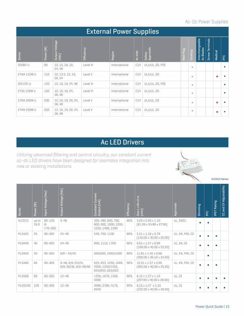
LED Drivers
Serie
s
Pow
er (W
)
Inpu
t Vol
tage
(Vac
)
Outp
ut V
olta
ge (V
dc)
Cons
tant
Cur
rent
Ou
tput
(mA)
Effici
ency
Size
L x
W x
H in
.(m
m)
Appr
oval
s
Dim
min
g
PFC
IP67
Rat
ing
CC a
nd C
V Ad
just
abili
tyVLED15 up to
16.990~135 & 176~265
5~48 350, 480, 600, 700, 800, 900, 1000, 1200, 1250, 1400, 1500
80% 3.20 x 2.20 x 1.10 (81.28 x 55.88 x 27.90)
UL, ENEC Δ Δ
PLDA25 25 90~305 24~48 530, 700, 1100 88% 5.51 x 1.18 x 0.78 (140.00 x 30.00 x 20.00)
UL, EN, PSE, CE Δ Δ ΔPLDA40 40 90~305 24~48 840, 1110, 1700 90% 6.61 x 1.57 x 0.99
(168.00 x 40.00 x 25.20)UL, EN, CE Δ Δ Δ
PLDA50 50 90~305 8/8 ~ 42/42 600/600, 1000/1000 86% 11.81 x 1.42 x 0.96 (300.00 x 36.10 x 24.50)
UL, EN, PSE, CE ΔPLDA60 60 90~305 9~48, 9/9~24/24,
9/9~36/36, 9/9~48/48 625, 833, 1250, 1666, 2500, 1250/1250, 833/833, 625/625
90% 10.31 x 1.57 x 0.99 (262.00 x 40.00 x 25.20)
UL, EN, PSE, CE Δ Δ Δ
PLDS60 60 90~305 12~48 1250, 1670, 1500, 5000
90% 8.15 x 1.57 x 1.10 (207.00 x 40.00 x 28.00)
UL, CE Δ Δ Δ ΔPLDS100 100 90~305 12~48 2080, 2780, 4170,
834090% 9.13 x 1.57 x 1.10
(232.00 x 40.00 x 28.00)UL, CE Δ Δ Δ Δ
Utilizing advanced filtering and control circuitry, our constant current ac-dc LED drivers have been designed for seamless integration into new or existing installations.
Ac LED Drivers
VLED15 Series
External Power Supplies
Serie
s
Pow
er (W
)
Outp
ut V
olta
ge
(Vdc
)
Effici
ency
Regi
on
Ac In
let
Safe
ty
Appr
oval
s
Wal
l Plu
g
Des
ktop
Inte
rcha
ngea
ble
Ac B
lade
s
Scre
w T
erm
inal
s
Med
ical
PFC
SDI90-U 90 12, 15, 18, 19, 24, 48
Level VI International C14 UL/cUL, GS, PSE ∫ ΔETMA 110W U 110 12, 13.5, 15, 19,
20, 24Level V International C14 UL/cUL, GS ∫ + Δ
SDI120-U 120 12, 16, 19, 24, 48 Level VI International C14 UL/cUL, GS, PSE ∫ ΔETSA 150W U 150 12, 16, 19, 24,
36, 48Level VI International C14 UL/cUL, GS ∫ Δ
ETMA 200W U 200 12, 16, 19, 20, 24, 36, 48
Level V International C14 UL/cUL, GS ∫ + ΔETMA 250W U 250 12, 16, 19, 20, 24,
36, 48Level V International C14 UL/cUL, GS ∫ + Δ
Ac-Dc Power Supplies
16 | Power Quick Guide
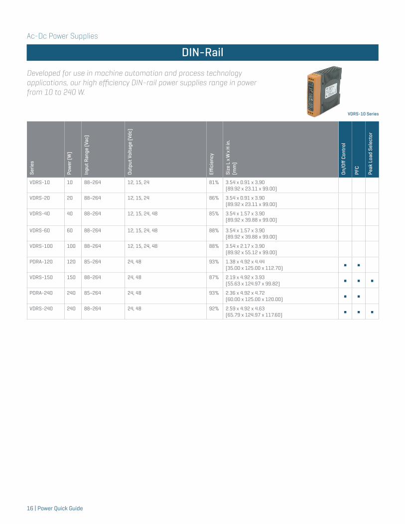
LED Drivers
Serie
s
Pow
er (W
)
Inpu
t Ran
ge (V
ac)
Outp
ut V
olta
ge (V
dc)
Effici
ency
Size
L x
W x
H in
.(m
m)
On/O
ff C
ontr
ol
PFC
Peak
Loa
d Se
lect
or
VDRS-10 10 88~264 12, 15, 24 81% 3.54 x 0.91 x 3.90 (89.92 x 23.11 x 99.00)
VDRS-20 20 88~264 12, 15, 24 86% 3.54 x 0.91 x 3.90 (89.92 x 23.11 x 99.00)
VDRS-40 40 88~264 12, 15, 24, 48 85% 3.54 x 1.57 x 3.90 (89.92 x 39.88 x 99.00)
VDRS-60 60 88~264 12, 15, 24, 48 88% 3.54 x 1.57 x 3.90 (89.92 x 39.88 x 99.00)
VDRS-100 100 88~264 12, 15, 24, 48 88% 3.54 x 2.17 x 3.90 (89.92 x 55.12 x 99.00)
PDRA-120 120 85~264 24, 48 93% 1.38 x 4.92 x 4.44(35.00 x 125.00 x 112.70) Δ Δ
VDRS-150 150 88~264 24, 48 87% 2.19 x 4.92 x 3.93 (55.63 x 124.97 x 99.82) Δ Δ Δ
PDRA-240 240 85~264 24, 48 93% 2.36 x 4.92 x 4.72(60.00 x 125.00 x 120.00) Δ Δ
VDRS-240 240 88~264 24, 48 92% 2.59 x 4.92 x 4.63 (65.79 x 124.97 x 117.60) Δ Δ Δ
Developed for use in machine automation and process technology applications, our high efficiency DIN-rail power supplies range in power from 10 to 240 W.
DIN-Rail
VDRS-10 Series
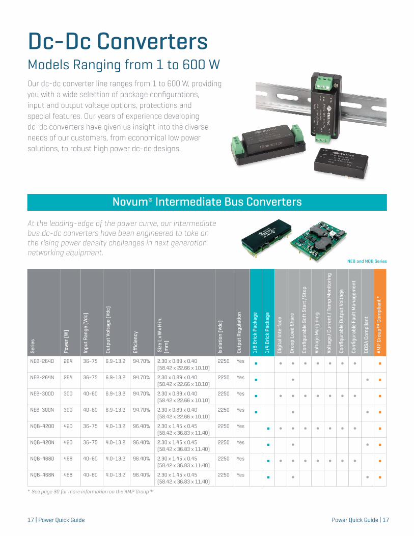
Dc-Dc ConvertersModels Ranging from 1 to 600 W Our dc-dc converter line ranges from 1 to 600 W, providing you with a wide selection of package configurations, input and output voltage options, protections and special features. Our years of experience developing dc-dc converters have given us insight into the diverse needs of our customers, from economical low power solutions, to robust high power dc-dc designs.
Power Quick Guide | 1717 | Power Quick Guide
Intermediate Bus Converters
Serie
s
Pow
er (W
)
Inpu
t Ran
ge (V
dc)
Outp
ut V
olta
ge (V
dc)
Effici
ency
Siz
e L x
W x
H in
.(m
m)
Isol
atio
n (V
dc)
Outp
ut R
egul
atio
n
1/8
Bric
k Pa
ckag
e
1/4
Bric
k Pa
ckag
e
Dig
ital I
nter
face
Dro
op L
oad
Shar
e
Confi
gura
ble
Soft
Sta
rt/S
top
Volta
ge M
argi
ning
Volta
ge/C
urre
nt/T
emp
Mon
itorin
g
Confi
gura
ble
Outp
ut V
olta
ge
Confi
gura
ble
Faul
t Man
agem
ent
DOS
A Co
mpl
iant
AMP
Grou
p™ C
ompl
iant
*
NEB-264D 264 36~75 6.9~13.2 94.70% 2.30 x 0.89 x 0.40 (58.42 x 22.66 x 10.10)
2250 Yes Δ ∫ ∫ ∫ ∫ ∫ ∫ ∫ ΔNEB-264N 264 36~75 6.9~13.2 94.70% 2.30 x 0.89 x 0.40
(58.42 x 22.66 x 10.10)2250 Yes Δ ∫ ∫ Δ
NEB-300D 300 40~60 6.9~13.2 94.70% 2.30 x 0.89 x 0.40(58.42 x 22.66 x 10.10)
2250 Yes Δ ∫ ∫ ∫ ∫ ∫ ∫ ∫ ΔNEB-300N 300 40~60 6.9~13.2 94.70% 2.30 x 0.89 x 0.40
(58.42 x 22.66 x 10.10)2250 Yes Δ ∫ ∫ Δ
NQB-420D 420 36~75 4.0~13.2 96.40% 2.30 x 1.45 x 0.45(58.42 x 36.83 x 11.40)
2250 Yes Δ ∫ ∫ ∫ ∫ ∫ ∫ ∫ ΔNQB-420N 420 36~75 4.0~13.2 96.40% 2.30 x 1.45 x 0.45
(58.42 x 36.83 x 11.40)2250 Yes Δ ∫ ∫ Δ
NQB-468D 468 40~60 4.0~13.2 96.40% 2.30 x 1.45 x 0.45(58.42 x 36.83 x 11.40)
2250 Yes Δ ∫ ∫ ∫ ∫ ∫ ∫ ∫ ΔNQB-468N 468 40~60 4.0~13.2 96.40% 2.30 x 1.45 x 0.45
(58.42 x 36.83 x 11.40)2250 Yes Δ ∫ ∫ Δ
NEB and NQB Series
At the leading-edge of the power curve, our intermediate bus dc-dc converters have been engineered to take on the rising power density challenges in next generation networking equipment.
Novum® Intermediate Bus Converters
* See page 30 for more information on the AMP Group™
Dc-Dc Converters
18 | Power Quick Guide
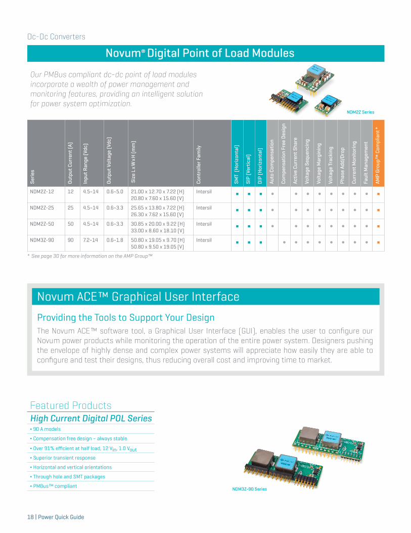
Novum® Digital Point of Load Modules
Our PMBus compliant dc-dc point of load modules incorporate a wealth of power management and monitoring features, providing an intelligent solution for power system optimization.
Serie
s
Outp
ut C
urre
nt (A
)
Inpu
t Ran
ge (V
dc)
Outp
ut V
olta
ge (V
dc)
Siz
e L x
W x
H (m
m)
Cont
rolle
r Fam
ily
SMT
(Hor
izon
tal)
SIP
(Ver
tical
)
DIP
(Hor
izon
tal)
Auto
Com
pens
atio
n
Com
pens
atio
n Fr
ee D
esig
n
Activ
e Cu
rren
t Sha
re
Volta
ge S
eque
ncin
g
Volta
ge M
argi
ning
Volta
ge T
rack
ing
Phas
e Ad
d/D
rop
Curr
ent M
onito
ring
Faul
t Man
agem
ent
AMP
Grou
p™ C
ompl
iant
*
NDM2Z-12 12 4.5~14 0.6~5.0 21.00 x 12.70 x 7.22 (H)20.80 x 7.60 x 15.60 (V)
Intersil Δ Δ Δ ∫ ∫ ∫ ∫ ∫ ∫ ∫ ∫ ΔNDM2Z-25 25 4.5~14 0.6~3.3 25.65 x 13.80 x 7.22 (H)
26.30 x 7.62 x 15.60 (V)Intersil Δ Δ Δ ∫ ∫ ∫ ∫ ∫ ∫ ∫ ∫ Δ
NDM2Z-50 50 4.5~14 0.6~3.3 30.85 x 20.00 x 9.22 (H)33.00 x 8.60 x 18.10 (V)
Intersil Δ Δ Δ ∫ ∫ ∫ ∫ ∫ ∫ ∫ ∫ ΔNDM3Z-90 90 7.2~14 0.6~1.8 50.80 x 19.05 x 9.70 (H)
50.80 x 9.50 x 19.05 (V)Intersil Δ Δ Δ ∫ ∫ ∫ ∫ ∫ ∫ ∫ ∫ Δ
Featured ProductsHigh Current Digital POL Series∆ 90 A models
∆ Compensation free design – always stable
∆ Over 91% efficient at half load, 12 Vin, 1.0 Vout
∆ Superior transient response
∆ Horizontal and vertical orientations
∆ Through hole and SMT packages
∆ PMBus™ compliant NDM3Z-90 Series
NDM2Z Series
Providing the Tools to Support Your DesignThe Novum ACE™ software tool, a Graphical User Interface (GUI), enables the user to configure our Novum power products while monitoring the operation of the entire power system. Designers pushing the envelope of highly dense and complex power systems will appreciate how easily they are able to configure and test their designs, thus reducing overall cost and improving time to market.
* See page 30 for more information on the AMP Group™
Novum ACE™ Graphical User Interface
Dc-Dc Converters
Power Quick Guide | 19
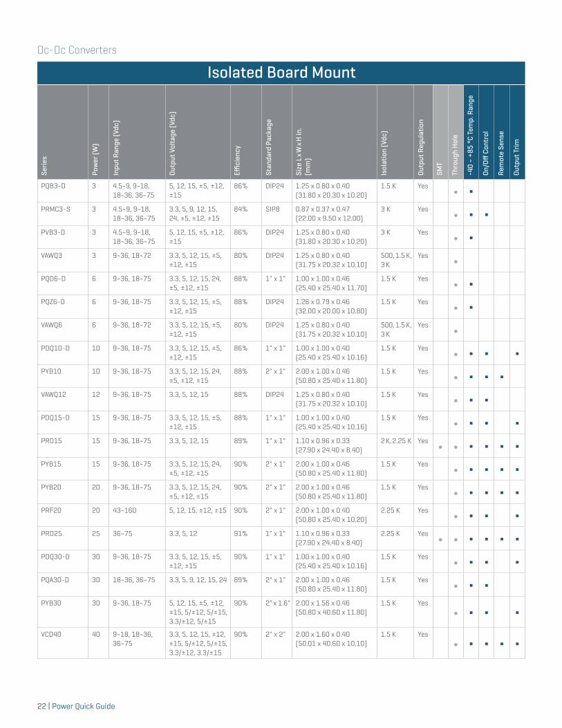
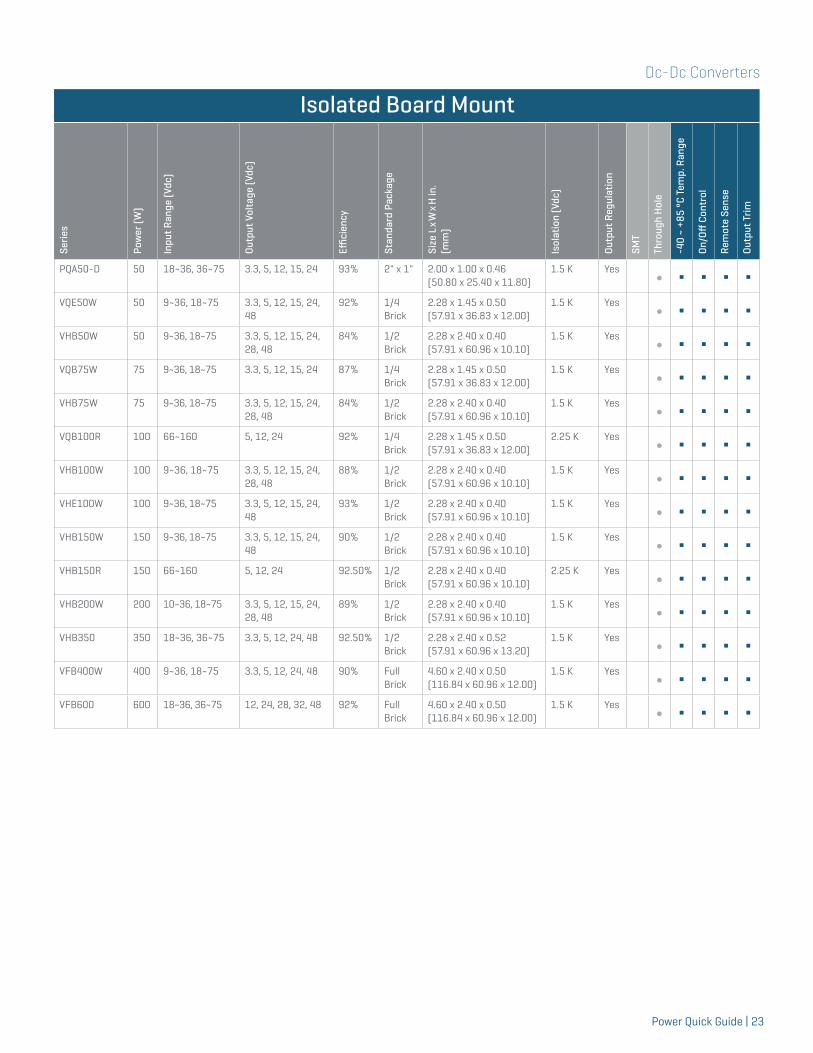
Isolated Board Mount
Serie
s
Pow
er (W
)
Inpu
t Ran
ge (V
dc)
Outp
ut V
olta
ge (V
dc)
Effici
ency
Stan
dard
Pac
kage
Size
L x
W x
H in
.(m
m)
Isol
atio
n (V
dc)
Outp
ut R
egul
atio
n
SMT
Thro
ugh
Hol
e
-40
~ +8
5 °C
Tem
p. R
ange
On/O
ff C
ontr
ol
Rem
ote
Sens
e
Outp
ut T
rim
PCM1-S 1 5 5 76% SIP7 0.77 x 0.24 x 0.4(19.60 x 6.00 x 10.20)
1 K No∫ Δ
PCM1-SA 1 5 5 76% SIP7 0.77 x 0.24 x 0.4(19.60 x 6.00 x 10.20)
1 K No∫ Δ
PCSA1-S 1 5, 12, 24 5, 12, 15 82% SIP4 0.46 x 0.24 x 0.40(11.60 x 6.00 x 10.20)
1 K No∫ Δ
PCN1-M 1 5, 12, 24 5, 12, 15, ±5, ±12, ±15
83% SMT8 0.54 x 0.36 x 0.29(13.70 x 9.20 x 7.40)
1.5 K No∫ Δ
PCN1-S 1 5, 12, 24 5, 12, 15, ±5, ±12, ±15
83% SIP7 0.77 x 0.24 x 0.40(19.50 x 6.10 x 10.20)
1.5 K No∫ Δ
PDS1-M 1 3.3, 5, 12, 15, 24 3.3, 5, 12, 15, 24, ±5, ±9, ±12, ±15, ±24
81% SMT8 0.50 x 0.33 x 0.29 (12.70 x 8.30 x 7.25)
1.5 K No
∫ ΔPDS1-S 1 3.3, 5, 12, 15, 24 3.3, 5, 9, 12, 15, 24 82% SIP4 0.46 x 0.24 x 0.39
(11.60 x 6.10 x 10.00)1.5 K No
∫ ΔPDS1-D 1 3.3, 5, 12, 15, 24 3.3, 5, 9, 12, 15, 24 82% DIP8 0.50 x 0.39 x 0.30
(12.70 x 10.00 x 7.70)1.5 K No
∫ ΔPDM1-S 1 5, 12, 15, 24 5, 12, 15, 24, ±5,
±12, ±15, ±2482% SIP6 0.77 x 0.24 x 0.35
(19.50 x 6.00 x 9.00)1.5 K No
∫ ΔVDSD1-SIP 1 5, 12, 15, 24 5/5, 9/9, 12/12,
15/1581% SIP7 0.77 x 0.24 x 0.39
(19.56 x 6.10 x 9.90)1 K No
∫ Δ
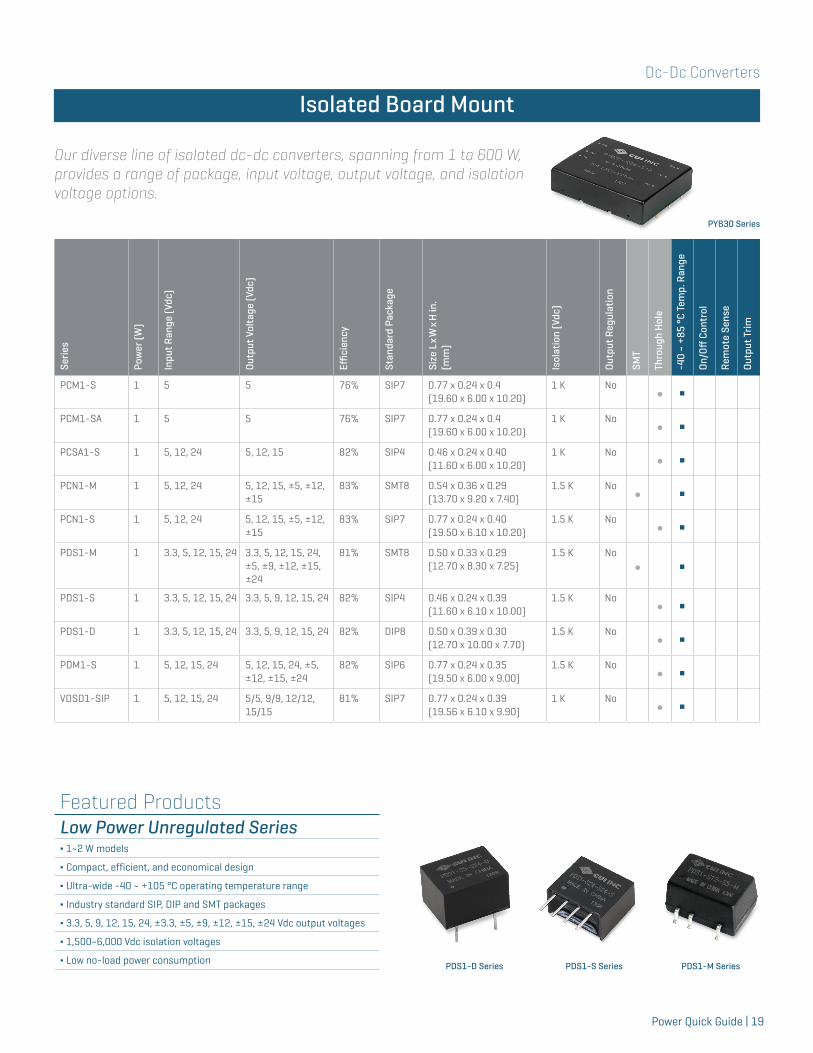
Our diverse line of isolated dc-dc converters, spanning from 1 to 600 W, provides a range of package, input voltage, output voltage, and isolation voltage options.
Isolated Board Mount
PYB30 Series
Featured ProductsLow Power Unregulated Series∆ 1~2 W models
∆ Compact, efficient, and economical design
∆ Ultra-wide -40 ~ +105 °C operating temperature range
∆ Industry standard SIP, DIP and SMT packages
∆ 3.3, 5, 9, 12, 15, 24, ±3.3, ±5, ±9, ±12, ±15, ±24 Vdc output voltages
∆ 1,500~6,000 Vdc isolation voltages
∆ Low no-load power consumption PDS1-S SeriesPDS1-D Series PDS1-M Series
Dc-Dc Converters
20 | Power Quick Guide
Isolated Board Mount
Serie
s
Pow
er (W
)
Inpu
t Ran
ge (V
dc)
Outp
ut V
olta
ge (V
dc)
Effici
ency
Stan
dard
Pac
kage
Size
L x
W x
H in
.(m
m)
Isol
atio
n (V
dc)
Outp
ut R
egul
atio
n
SMT
Thro
ugh
Hol
e
-40
~ +8
5 °C
Tem
p. R
ange
On/O
ff C
ontr
ol
Rem
ote
Sens
e
Outp
ut T
rim
VDSD1-DIP 1 5, 12, 15, 24 5/5, 9/9, 12/12, 15/15
81% DIP14 0.80 x 0.39 x 0.26 (20.32 x 9.91 x 6.60)
1 K No∫ Δ
PHP1-M 1 3.3, 5, 12, 15 5, 12, 15 76% SMT8 0.50 x 0.42 x 0.28(12.75 x 10.70 x 7.00)
2 K No∫ Δ
PES1-M 1 3.3, 5, 12, 15, 24
3.3, 5, 9, 12, 15, 24, ±5, ±9, ±12, ±15, ±24
82% SMT8 0.50 x 0.33 x 0.29 (12.70 x 8.30 x 7.25)
3 K No
∫ ΔPEM1-S 1 5, 12, 15, 24 5, 12, 15, 24, ±5,
±12, ±15, ±2482% SIP7 0.77 x 0.20 x 0.35
(19.50 x 6.00 x 9.00)3 K No
∫ ΔVESD1-DIP 1 5, 12, 15, 24 ±5, ±9, ±12, ±15 81% DIP14 0.80 x 0.39 x 0.26
(20.32 x 9.91 x 6.60)3 K No
∫ ΔVFSD1-DIP 1 3.3, 5, 12, 15, 24 3.3, 5, 9, 12, 15 82% DIP14 0.80 x 0.39 x 0.26
(20.32 x 9.91 x 6.60)3 K No
∫ ΔPEM1A-S 1 5 5 70% SIP7 0.77 x 0.28 x 0.40
(19.60 x 7.05 x 10.20)4 K No
∫ ΔVGDS1-SIP 1 5, 12, 15, 24 ±5, ±9, ±12, ±15 78% SIP7 0.77 x 0.39 x 0.49
(19.56 x 9.91 x 12.00)6 K No
∫ ΔVGDS1-DIP 1 5, 12, 15, 24 ±5, ±9, ±12, ±15 80% DIP24 1.27 x 0.58 x 0.37
(32.26 x 14.73 x 9.39)6 K No
∫ ΔVHS1-SIP 1 5, 12, 15, 24 5, 9, 12, 15 78% SIP7 0.77 x 0.39 x 0.49
(19.56 x 9.91 x 12.00)6 K No
∫ ΔVHD1-DIP 1 5, 12, 15, 24 5, 9, 12, 15 75% DIP24 1.27 x 0.58 x 0.37
(32.26 x 14.73 x 9.39)6 K No
∫ ΔPQM1-M 1 5, 12, 24 3.3, 5, 9, 12, 15 75% SMT10 0.60 x 0.44 x 0.29
(15.24 x 11.20 x 7.25)1.5 K Yes
∫ ΔVIAS1-SIP 1 5, 12, 15, 24 ±5, ±9, ±12, ±15 73% SIP10 1.08 x 0.35 x 0.43
(27.43 x 8.81 x 10.92)1 K Yes
∫ ΔVIBLSD1-SIP 1 5, 12, 15, 24 5, 9, 12, 15 73% SIP6 0.77 x 0.24 x 0.39
(19.56 x 6.10 x 9.90)1 K Yes
∫ ΔVIBLSD1-DIP 1 5, 12, 15, 24 5, 9, 12, 15 73% DIP14 0.80 x 0.39 x 0.26
(20.32 x 9.91 x 6.60)1 K Yes
∫ ΔVIESD1-SIP 1 5, 12, 24 5, 9, 12, 15 73% SIP10 1.08 x 0.47 x 0.37
(27.43 x 11.94 x 9.39)3 K Yes
∫ ΔVIFSD1-DIP 1 5, 12, 24 5, 9, 12, 15 73% DIP14 0.77 x 0.25 x 0.39
(19.56 x 6.35 x 9.91)3 K Yes
∫ ΔVIFSD1-SIP 1 5, 12, 15, 24 5, 12, 15, 24 73% SIP6 0.80 x 0.39 x 0.26
(20.32 x 9.91 x 6.60)3 K Yes
∫ ΔPQMC1-S 1 4.5~9, 9~18,
18~36, 36~755, 12, 15, ±5, ±12, ±15
81% SIP8 0.87 x 0.37 x 0.47 (22.00 x 9.50 x 12.00)
1.5 K Yes∫ Δ Δ
PRMC1-S 1 4.5~9, 9~18, 18~36, 36~75
3.3, 5, 9, 12, 15, 24, ±5, ±12, ±15
82% SIP8 0.87 x 0.37 x 0.47 (22.00 x 9.50 x 12.00)
3 K Yes∫ Δ Δ
Dc-Dc Converters
Power Quick Guide | 21
Isolated Board Mount
Serie
s
Pow
er (W
)
Inpu
t Ran
ge (V
dc)
Outp
ut V
olta
ge (V
dc)
Effici
ency
Stan
dard
Pac
kage
Size
L x
W x
H in
.(m
m)
Isol
atio
n (V
dc)
Outp
ut R
egul
atio
n
SMT
Thro
ugh
Hol
e
-40
~ +8
5 °C
Tem
p. R
ange
On/O
ff C
ontr
ol
Rem
ote
Sens
e
Outp
ut T
rim
VAT2-SMT 2 5, 12 ±5, ±9, ±12, ±15 85% SMT14 0.70 x 0.50 x 0.24 (17.78 x 12.01 x 6.09)
1 K No∫ Δ
PCN2-S 2 5, 12, 24 5, 12, 15, ±5, ±12, ±15
86% SIP7 0.77 x 0.28 x 0.40(19.60 x 7.20 x 10.20)
1 K No∫ Δ
PDS2-M 2 5, 12, 15, 24 3.3, 5, 9, 12, 15, 24 86% SMT8 0.50 x 0.44 x 0.29 (12.70 x 11.20 x 7.25)
1.5 K No∫ Δ
PDM2-S 2 5, 12, 15, 24 5, 12, 15, 24, ±5, ±12, ±15, ±24
89% SIP7 0.77 x 0.28 x 0.50 (19.60 x 7.00 x 10.00)
1.5 K No∫ Δ
PDM2-D 2 3.3, 5, 12, 24 5, 9, 12, 15, 24, ±5, ±9, ±12, ±15
85% DIP14 0.79 x 0.39 x 0.32 (20.00 x 10.00 x 8.20)
1.5 K No∫ Δ
PEM2-D 2 5, 12, 15, 24 5, 9, 12, 15, ±5, ±12, ±15
85% DIP14 0.79 x 0.39 x 0.32(20.00 x 10.00 x 8.20)
3 K No∫ Δ
PEM2-S 2 5, 12, 15, 24 5, 12, 15, 24, ±5, ±12, ±15, ±24
89% SIP7 0.77 x 0.28 x 0.50 (19.60 x 7.00 x 10.00)
3 K No∫ Δ
VGDS2-SIP 2 5, 12 ±5, ±9, ±12, ±15 85% SIP7 0.77 x 0.39 x 0.49 (19.56 x 9.91 x 12.00]
6 K No∫ Δ
VGDS2-DIP 2 5, 12 ±5, ±9, ±12, ±15 85% DIP24 1.27 x 0.58 x 0.37 (32.26 x 14.73 x 9.39)
6 K No∫ Δ
VHS2-SIP 2 5, 12 5, 9, 12, 15 84% SIP7 0.77 x 0.39 x 0.49 (19.56 x 9.91 x 12.00)
6 K No∫ Δ
VHD2-DIP 2 5, 12 5, 9, 12, 15 82% DIP24 1.27 x 0.58 x 0.37 (32.26 x 14.73 x 9.39)
6 K No∫ Δ
PDQ2-S 2 4.5~9, 9~18, 18~36, 36~75
3.3, 5, 12, 15, ±5, ±12, ±15
84% SIP8 0.86 x 0.36 x 0.44(21.80 x 9.20 x 11.10)
1.5 K Yes∫ Δ Δ
PQMC3-S 3 4.5~9, 9~18, 18~36, 36~75
5, 12, 15, ±5, ±12, ±15
82% SIP8 0.87 x 0.37 x 0.47 (22.00 x 9.50 x 12.00)
1.5 K Yes∫ Δ Δ
PQM3-M 3 4.5~9, 9~18, 18~36, 36~75
5, 12, 15 80% SMT16 0.94 x 0.54 x 0.30 (23.86 x 13.70 x 7.50)
1.5 K Yes∫ Δ
PUZ3-D 3 4.5~9, 9~18, 18~36, 36~75
5, 12, 15, 24, ±5, ±12, ±15
86% DIP24 1.26 x 0.79 x 0.43 (32.00 x 20.00 x 10.80)
1.5 K Yes∫ Δ
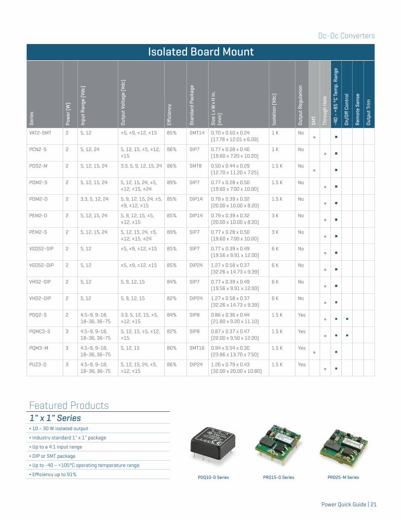
Featured Products1" x 1" Series∆ 10 ~ 30 W isolated output
∆ Industry standard 1" x 1" package
∆ Up to a 4:1 input range
∆ DIP or SMT package
∆ Up to -40 ~ +105°C operating temperature range
∆ Efficiency up to 91% PRD15-D SeriesPDQ10-D Series PRD25-M Series
Dc-Dc Converters
22 | Power Quick Guide
Isolated Board Mount
Serie
s
Pow
er (W
)
Inpu
t Ran
ge (V
dc)
Outp
ut V
olta
ge (V
dc)
Effici
ency
Stan
dard
Pac
kage
Size
L x
W x
H in
.(m
m)
Isol
atio
n (V
dc)
Outp
ut R
egul
atio
n
SMT
Thro
ugh
Hol
e
-40
~ +8
5 °C
Tem
p. R
ange
On/O
ff C
ontr
ol
Rem
ote
Sens
e
Outp
ut T
rim
PQB3-D 3 4.5~9, 9~18, 18~36, 36~75
5, 12, 15, ±5, ±12, ±15
86% DIP24 1.25 x 0.80 x 0.40 (31.80 x 20.30 x 10.20)
1.5 K Yes∫ Δ
PRMC3-S 3 4.5~9, 9~18, 18~36, 36~75
3.3, 5, 9, 12, 15, 24, ±5, ±12, ±15
84% SIP8 0.87 x 0.37 x 0.47 (22.00 x 9.50 x 12.00)
3 K Yes∫ Δ Δ
PVB3-D 3 4.5~9, 9~18, 18~36, 36~75
5, 12, 15, ±5, ±12, ±15
86% DIP24 1.25 x 0.80 x 0.40 (31.80 x 20.30 x 10.20)
3 K Yes∫ Δ
VAWQ3 3 9~36, 18~72 3.3, 5, 12, 15, ±5, ±12, ±15
80% DIP24 1.25 x 0.80 x 0.40 (31.75 x 20.32 x 10.10)
500, 1.5 K, 3 K
Yes∫
PQD6-D 6 9~36, 18~75 3.3, 5, 12, 15, 24, ±5, ±12, ±15
88% 1" x 1" 1.00 x 1.00 x 0.46 (25.40 x 25.40 x 11.70)
1.5 K Yes∫ Δ
PQZ6-D 6 9~36, 18~75 3.3, 5, 12, 15, ±5, ±12, ±15
88% DIP24 1.26 x 0.79 x 0.46 (32.00 x 20.00 x 10.80)
1.5 K Yes∫ Δ
VAWQ6 6 9~36, 18~72 3.3, 5, 12, 15, ±5, ±12, ±15
80% DIP24 1.25 x 0.80 x 0.40 (31.75 x 20.32 x 10.10)
500, 1.5 K, 3 K
Yes∫
PDQ10-D 10 9~36, 18~75 3.3, 5, 12, 15, ±5, ±12, ±15
86% 1" x 1" 1.00 x 1.00 x 0.40(25.40 x 25.40 x 10.16)
1.5 K Yes∫ Δ Δ Δ
PYB10 10 9~36, 18~75 3.3, 5, 12, 15, 24, ±5, ±12, ±15
88% 2" x 1" 2.00 x 1.00 x 0.46 (50.80 x 25.40 x 11.80)
1.5 K Yes∫ Δ Δ Δ
VAWQ12 12 9~36, 18~75 3.3, 5, 12, 15 88% DIP24 1.25 x 0.80 x 0.40 (31.75 x 20.32 x 10.10)
1.5 K Yes∫ Δ Δ
PDQ15-D 15 9~36, 18~75 3.3, 5, 12, 15, ±5, ±12, ±15
88% 1" x 1" 1.00 x 1.00 x 0.40(25.40 x 25.40 x 10.16)
1.5 K Yes∫ Δ Δ Δ
PRD15 15 9~36, 18~75 3.3, 5, 12, 15 89% 1" x 1" 1.10 x 0.96 x 0.33(27.90 x 24.40 x 8.40)
2 K, 2.25 K Yes∫ ∫ Δ Δ Δ Δ
PYB15 15 9~36, 18~75 3.3, 5, 12, 15, 24, ±5, ±12, ±15
90% 2" x 1" 2.00 x 1.00 x 0.46 (50.80 x 25.40 x 11.80)
1.5 K Yes∫ Δ Δ Δ Δ
PYB20 20 9~36, 18~75 3.3, 5, 12, 15, 24, ±5, ±12, ±15
90% 2" x 1" 2.00 x 1.00 x 0.46 (50.80 x 25.40 x 11.80)
1.5 K Yes∫ Δ Δ Δ Δ
PRF20 20 43~160 5, 12, 15, ±12, ±15 90% 2" x 1" 2.00 x 1.00 x 0.40 (50.80 x 25.40 x 10.20)
2.25 K Yes∫ Δ Δ Δ
PRD25 25 36~75 3.3, 5, 12 91% 1" x 1" 1.10 x 0.96 x 0.33(27.90 x 24.40 x 8.40)
2.25 K Yes∫ ∫ Δ Δ Δ Δ
PDQ30-D 30 9~36, 18~75 3.3, 5, 12, 15, ±5, ±12, ±15
90% 1" x 1" 1.00 x 1.00 x 0.40(25.40 x 25.40 x 10.16)
1.5 K Yes∫ Δ Δ Δ
PQA30-D 30 18~36, 36~75 3.3, 5, 9, 12, 15, 24 89% 2" x 1" 2.00 x 1.00 x 0.46 (50.80 x 25.40 x 11.80)
1.5 K Yes∫ Δ Δ
PYB30 30 9~36, 18~75 5, 12, 15, ±5, ±12, ±15, 5/±12, 5/±15, 3.3/±12, 5/±15
90% 2" x 1.6" 2.00 x 1.56 x 0.46 (50.80 x 40.60 x 11.80)
1.5 K Yes
∫ Δ Δ Δ
VCD40 40 9~18, 18~36, 36~75
3.3, 5, 12, 15, ±12, ±15, 5/±12, 5/±15, 3.3/±12, 3.3/±15
90% 2" x 2" 2.00 x 1.60 x 0.40 (50.01 x 40.60 x 10.10)
1.5 K Yes
∫ Δ Δ Δ Δ
Dc-Dc Converters
Power Quick Guide | 23
Isolated Board Mount
Serie
s
Pow
er (W
)
Inpu
t Ran
ge (V
dc)
Outp
ut V
olta
ge (V
dc)
Effici
ency
Stan
dard
Pac
kage
Size
L x
W x
H in
.(m
m)
Isol
atio
n (V
dc)
Outp
ut R
egul
atio
n
SMT
Thro
ugh
Hol
e
-40
~ +8
5 °C
Tem
p. R
ange
On/O
ff C
ontr
ol
Rem
ote
Sens
e
Outp
ut T
rim
PQA50-D 50 18~36, 36~75 3.3, 5, 12, 15, 24 93% 2" x 1" 2.00 x 1.00 x 0.46 (50.80 x 25.40 x 11.80)
1.5 K Yes∫ Δ Δ Δ Δ
VQE50W 50 9~36, 18~75 3.3, 5, 12, 15, 24, 48
92% 1/4 Brick
2.28 x 1.45 x 0.50 (57.91 x 36.83 x 12.00)
1.5 K Yes∫ Δ Δ Δ Δ
VHB50W 50 9~36, 18~75 3.3, 5, 12, 15, 24, 28, 48
84% 1/2 Brick
2.28 x 2.40 x 0.40 (57.91 x 60.96 x 10.10)
1.5 K Yes∫ Δ Δ Δ Δ
VQB75W 75 9~36, 18~75 3.3, 5, 12, 15, 24 87% 1/4 Brick
2.28 x 1.45 x 0.50 (57.91 x 36.83 x 12.00)
1.5 K Yes∫ Δ Δ Δ Δ
VHB75W 75 9~36, 18~75 3.3, 5, 12, 15, 24, 28, 48
84% 1/2 Brick
2.28 x 2.40 x 0.40 (57.91 x 60.96 x 10.10)
1.5 K Yes∫ Δ Δ Δ Δ
VQB100R 100 66~160 5, 12, 24 92% 1/4 Brick
2.28 x 1.45 x 0.50 (57.91 x 36.83 x 12.00)
2.25 K Yes∫ Δ Δ Δ Δ
VHB100W 100 9~36, 18~75 3.3, 5, 12, 15, 24, 28, 48
88% 1/2 Brick
2.28 x 2.40 x 0.40 (57.91 x 60.96 x 10.10)
1.5 K Yes∫ Δ Δ Δ Δ
VHE100W 100 9~36, 18~75 3.3, 5, 12, 15, 24, 48
93% 1/2 Brick
2.28 x 2.40 x 0.40 (57.91 x 60.96 x 10.10)
1.5 K Yes∫ Δ Δ Δ Δ
VHB150W 150 9~36, 18~75 3.3, 5, 12, 15, 24, 48
90% 1/2 Brick
2.28 x 2.40 x 0.40 (57.91 x 60.96 x 10.10)
1.5 K Yes∫ Δ Δ Δ Δ
VHB150R 150 66~160 5, 12, 24 92.50% 1/2 Brick
2.28 x 2.40 x 0.40 (57.91 x 60.96 x 10.10)
2.25 K Yes∫ Δ Δ Δ Δ
VHB200W 200 10~36, 18~75 3.3, 5, 12, 15, 24, 28, 48
89% 1/2 Brick
2.28 x 2.40 x 0.40 (57.91 x 60.96 x 10.10)
1.5 K Yes∫ Δ Δ Δ Δ
VHB350 350 18~36, 36~75 3.3, 5, 12, 24, 48 92.50% 1/2 Brick
2.28 x 2.40 x 0.52 (57.91 x 60.96 x 13.20)
1.5 K Yes∫ Δ Δ Δ Δ
VFB400W 400 9~36, 18~75 3.3, 5, 12, 24, 48 90% Full Brick
4.60 x 2.40 x 0.50 (116.84 x 60.96 x 12.00)
1.5 K Yes∫ Δ Δ Δ Δ
VFB600 600 18~36, 36~75 12, 24, 28, 32, 48 92% Full Brick
4.60 x 2.40 x 0.50 (116.84 x 60.96 x 12.00)
1.5 K Yes∫ Δ Δ Δ Δ
Dc-Dc Converters
24 | Power Quick Guide
Isolated Chassis Mount
Serie
s
Pow
er (W
)
Inpu
t Ran
ge (V
dc)
Outp
ut V
olta
ge (V
dc)
Effici
ency
Size
L x
W x
H in
. (m
m)
Isol
atio
n (V
dc)
Outp
ut R
egul
atio
n
-40
~ +8
5 °C
Tem
p. R
ange
On/O
ff C
ontr
ol
Rem
ote
Sens
e
Outp
ut T
rim
PYB10-U 10 9~36, 18~75 3.3, 5, 12, 24, ±5, ±12, ±15 88% 2.66 x 2.16 x 0.75(67.50 x 55.00 x 19.10)
1.5 K YesΔ Δ
PYB10-T 10 9~36, 18~75 3.3, 5, 12, 24, ±5, ±12, ±15 88% 2.99 x 1.24 x 0.83(76.00 x 31.50 x 21.20)
1.5 K YesΔ Δ
PYB15-U 15 9~36, 18~75 3.3, 5, 12, 15, 24, ±5, ±12, ±15 90% 2.66 x 2.16 x 0.75 (67.50 x 55.00 x 19.10)
1.5 K YesΔ Δ Δ
PYB15-T 15 9~36, 18~75 3.3, 5, 12, 15, 24, ±5, ±12, ±15 90% 2.99 x 1.24 x 0.83(76.00 x 31.50 x 21.20)
1.5 K YesΔ Δ Δ
PYB20-U 20 9~36, 18~75 3.3, 5, 12, 15, 24, ±5, ±12, ±15 90% 2.66 x 2.16 x 0.75(67.50 x 55.00 x 19.10)
1.5 K YesΔ Δ Δ
PYB20-T 20 9~36, 18~75 3.3, 5, 12, 15, 24, ±5, ±12, ±15 90% 2.99 x 1.24 x 0.83(76.00 x 31.50 x 21.20)
1.5 K YesΔ Δ Δ
PYB30-U 30 9~36, 18~75 5, 12, 15, ±5, ±12, ±15, 5/±12, 5/±15, 3.3/±12, 5/±15
90% 2.66 x 2.16 x 0.75(67.50 x 55.00 x 19.10)
1.5 K YesΔ Δ Δ
PQA30-T 30 18~36, 36~75 3.3, 5, 12, 15, 24 87% 2.99 x 1.24 x 0.83(76.00 x 31.50 x 21.20
1.5 K YesΔ Δ
PQA50-T 50 18~36, 36~75 3.3, 5, 12, 15, 24 91% 2.99 x 1.24 x 0.83(76.00 x 31.50 x 21.20)
1.5 K YesΔ Δ
VHK50W 50 9~36, 18~75 3.3, 5, 12, 15, 24, 28, 48 84% 4.33 x 3.98 x 1.50(109.98 x 101.09 x 38.00)
1.5 K YesΔ Δ Δ Δ
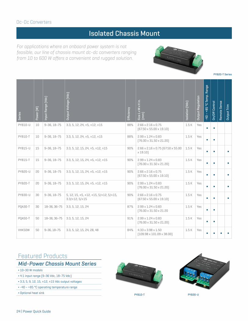
For applications where an onboard power system is not feasible, our line of chassis mount dc-dc converters ranging from 10 to 600 W offers a convenient and rugged solution.
Isolated Chassis Mount
PYB20-T Series
Featured ProductsMid-Power Chassis Mount Series∆ 10~30 W models
∆ 4:1 input range (9~36 Vdc, 18~75 Vdc)
∆ 3.3, 5, 9, 12, 15, ±12, ±15 Vdc output voltages
∆ -40 ~ +85 °C operating temperature range
∆ Optional heat sink PYB10-T PYB30-U
Dc-Dc Converters
Power Quick Guide | 25
Isolated Chassis Mount
Serie
s
Pow
er (W
)
Inpu
t Ran
ge (V
dc)
Outp
ut V
olta
ge (V
dc)
Effici
ency
Size
L x
W x
H in
. (m
m)
Isol
atio
n (V
dc)
Outp
ut R
egul
atio
n
-40
~ +8
5 °C
Tem
p. R
ange
On/O
ff C
ontr
ol
Rem
ote
Sens
e
Outp
ut T
rim
VHK75W 75 9~36, 18~75 3.3, 5, 12, 15, 24, 28, 48 85% 4.33 x 3.98 x 1.50(109.98 x 101.09 x 38.00)
1.5 K YesΔ Δ Δ Δ
VHK100W 100 9~36, 18~75 3.3, 5, 12, 15, 24, 28, 48 85% 4.33 x 3.98 x 1.50(109.98 x 101.09 x 38.00)
1.5 K YesΔ Δ Δ Δ
VHK150W 150 9~36, 18~75 12, 15, 24, 48 90% 4.33 x 3.98 x 1.50(109.98 x 101.09 x 38.00)
1.5 K YesΔ Δ Δ Δ
VHK200W 200 10~36, 18~75 12, 15, 24, 28, 48 89% 4.33 x 3.98 x 1.50(109.98 x 101.09 x 38.00)
1.5 K YesΔ Δ Δ Δ
VFK400W 400 10~36, 18~75 12, 24, 48 89% 7.61 x 4.99 x 1.53(195.33 x 126.75 x 38.01)
1.5 K YesΔ Δ Δ Δ
VFK600 600 18-36, 36-75 12, 24, 28, 32, 48 92% 7.61 x 4.99 x 1.53(195.33 x 126.75 x 38.01)
1.5 K YesΔ Δ Δ Δ
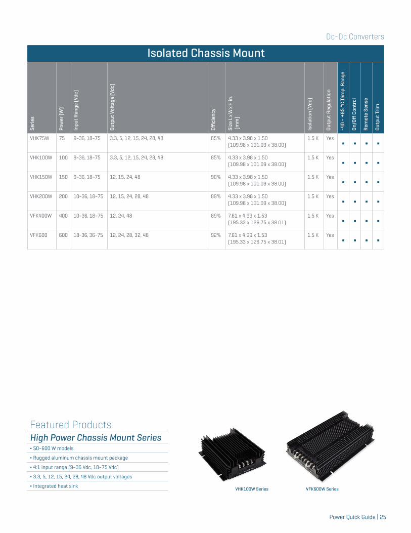
Featured ProductsHigh Power Chassis Mount Series∆ 50~600 W models
∆ Rugged aluminum chassis mount package
∆ 4:1 input range (9~36 Vdc, 18~75 Vdc)
∆ 3.3, 5, 12, 15, 24, 28, 48 Vdc output voltages
∆ Integrated heat sink VHK100W Series VFK600W Series
Dc-Dc Converters
26 | Power Quick Guide
Isolated DIN Rail
Serie
s
Pow
er (W
)
Inpu
t Ran
ge (V
dc)
Outp
ut V
olta
ge (A
)
Effici
ency
Size
L x
W x
H in
.(m
m)
Isol
atio
n (V
dc)
Outp
ut R
egul
atio
n
-40
~ +8
5 °C
Tem
p. R
ange
On/O
ff C
ontr
ol
Rem
ote
Sens
e
Outp
ut T
rim
PYB10-DIN 10 9~36, 18~75 3.3, 5, 12, 24, ±5, ±12, ±15 88% 2.99 x 1.24 x 1.02 (76.00 x 31.50 x 25.80)
1.5 K Yes Δ ΔPYB15-DIN 15 9~36, 18~75 3.3, 5, 12, 15, 24, ±5, ±12, ±15 90% 2.99 x 1.24 x 1.02
(76.00 x 31.50 x 25.80)1.5 K Yes Δ Δ Δ
PYB20-DIN 20 9~36, 18~75 3.3, 5, 12, 15, 24, ±5, ±12, ±15 90% 2.99 x 1.24 x 1.02 (76.00 x 31.50 x 25.80)
1.5 K Yes Δ Δ ΔVHK50W-DIN 50 9~36, 18~75 3.3, 5, 12, 15, 24, 28, 48 83% 4.23 x 4.01 x 2.07
(107.50 x 101.80 x 52.60)1.5 K Yes Δ Δ Δ Δ
VHK75W-DIN 75 9~36 , 18~75 3.3, 5, 12, 15, 24, 48 84% 4.23 x 4.01 x 2.07 (107.50 x 101.80 x 52.60)
1.5 K Yes Δ Δ Δ ΔVHK100W-DIN 100 9~36, 18~75 3.3, 5, 12, 15, 24, 28, 48 87% 4.23 x 4.01 x 2.07
(107.50 x 101.80 x 52.60)1.5 K Yes Δ Δ Δ Δ
VHK150W-DIN 150 9~36, 18~75 5, 12, 15, 24, 28, 48 90% 4.23 x 4.01 x 2.07 (107.50 x 101.80 x 52.60)
1.5 K Yes Δ Δ Δ ΔVHK200W-DIN 200 10~36, 18~75 12, 15, 24, 28, 48 88% 4.23 x 4.01 x 2.07
(107.50 x 101.80 x 52.60)1.5 K Yes Δ Δ Δ Δ
VFK400W-DIN 400 10~36, 18~75 12, 24, 48 89% 7.83 x 5.00 x 2.11 (199.00 x 127.00 x 53.60)
1.5 K Yes Δ Δ Δ ΔVFK600-DIN 600 18~36, 36~75 12, 24, 28, 32, 48 92% 7.83 x 5.00 x 2.11
(199.00 x 127.00 x 53.60)1.5 K Yes Δ Δ Δ Δ
Isolated DIN-Rail
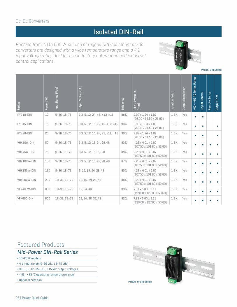
Ranging from 10 to 600 W, our line of rugged DIN-rail mount dc-dc converters are designed with a wide temperature range and a 4:1 input voltage ratio, ideal for use in factory automation and industrial control applications.
PYB15-DIN Series
Featured ProductsMid-Power DIN-Rail Series∆ 10~20 W models
∆ 4:1 input range (9~36 Vdc, 18~75 Vdc)
∆ 3.3, 5, 9, 12, 15, ±12, ±15 Vdc output voltages
∆ -40 ~ +85 °C operating temperature range
∆ Optional heat sink PYB20-H-DIN Series
Dc-Dc Converters
Power Quick Guide | 27
Serie
s
Cons
tant
Cur
rent
Out
put
(mA)
Inpu
t Ran
ge (V
dc)
Outp
ut V
olta
ge (V
dc)
Effici
ency
Size
L x
W x
H in
.(m
m)
SMT
Thro
ugh
Hol
e
Anal
og D
imm
ing
-40
~ +8
5 °C
Tem
p. R
ange
On/O
ff C
ontr
ol
VLD25-XX-DIP 300, 350, 500, 600, 700 5.5~46 3.3~36 95% 0.90 x 0.40 x 0.35(22.86 x 10.10 x 8.80) ∫ Δ Δ Δ
VLD25-XX-SMT 300, 350, 500, 600, 700 5.5~48 3.3~36 96% 0.94 x 0.54 x 0.32(23.88 x 13.72 x 8.12) ∫ Δ Δ Δ
Dc LED Drivers
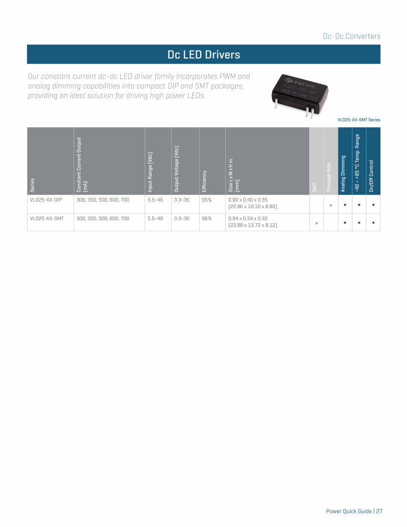
Our constant current dc-dc LED driver family incorporates PWM and analog dimming capabilities into compact DIP and SMT packages, providing an ideal solution for driving high power LEDs.
VLD25-XX-SMT Series
Dc-Dc Converters
28 | Power Quick Guide
Non-Isolated
Serie
s
Outp
ut C
urre
nt (A
)
Inpu
t Ran
ge (V
dc)
Outp
ut V
olta
ge (V
dc)
Effici
ency
Size
L x
W x
H in
.(m
m)
Outp
ut R
egul
atio
n
SMT
Thro
ugh
Hol
e
Righ
t-An
gle
Vers
ion
On/O
ff C
ontr
ol
Outp
ut T
rim
P7805-S 0.5 4.75~32 1.5, 1.8, 2.5, 3.3, 5, 6.5, 9, 12, 15 96% 0.46 x 0.30 x 0.40 (11.60 x 7.50 x 10.20)
Yes∫
P78A-0500 0.5 6~28 3.3, 5 95% 0.46 x 0.34 x 0.41(11.60 x 8.50 x 10.40)
Yes∫
V78W-500 0.5 9~72 3.3, 5, 6.5, 9, 12, 15, 24 95% 0.45 x 0.35 x 0.69 (11.43 x 8.81 x 17.52)
Yes∫ Δ
V78-500-SMT 0.5 4.5~28 3.3, 5, 12, 15 96% 0.60 x 0.33 x 0.29(15.24 x 8.30 x 7.25)
Yes∫ Δ
P78A-1000 1 7~28 3.3, 5 91% 0.46 x 0.34 x 0.41(11.60 x 8.50 x 10.40)
Yes∫
V78-1000 1 4.5~32 3.3, 5, 6.5, 9, 12, 15 97% 0.69 x 0.45 x 0.35(17.50 x 11.50 x 9.00)
Yes∫ Δ
V78-1000-SMT 1 5~18 1.5, 1.8, 2.5, 3.3, 5, 6.5 93% 0.60 x 0.33 x 0.28(15.24 x 8.30 x 7.25)
Yes∫ Δ Δ
V78-1500 1.5 4.75~18 3.3, 5, 6.5 95% 0.69 x 0.45 x 0.35(17.50 x 11.50 x 9.00)
Yes∫ Δ
V78-2000 2 4.75~18 3.3, 5, 6.5 95% 0.69 x 0.45 x 0.35(17.50 x 11.50 x 9.00)
Yes∫ Δ
Non-Isolated
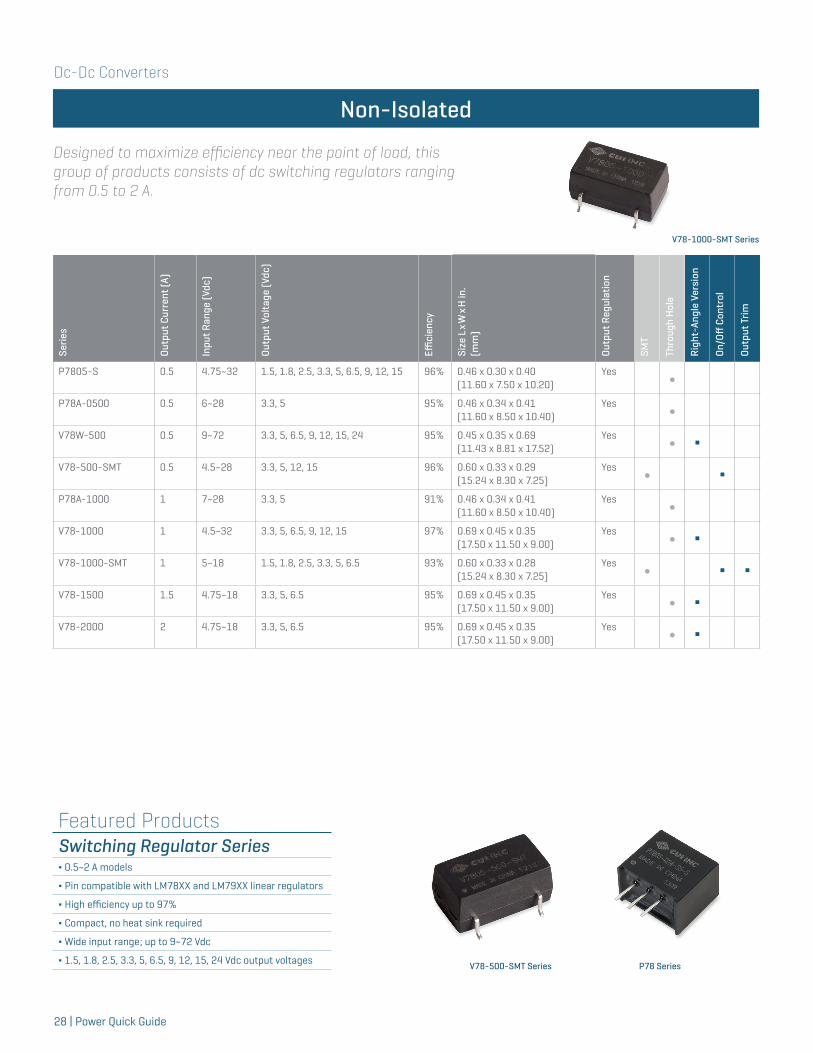
Designed to maximize efficiency near the point of load, this group of products consists of dc switching regulators ranging from 0.5 to 2 A.
V78-1000-SMT Series
Featured ProductsSwitching Regulator Series∆ 0.5~2 A models
∆ Pin compatible with LM78XX and LM79XX linear regulators
∆ High efficiency up to 97%
∆ Compact, no heat sink required
∆ Wide input range; up to 9~72 Vdc
∆ 1.5, 1.8, 2.5, 3.3, 5, 6.5, 9, 12, 15, 24 Vdc output voltages V78-500-SMT Series P78 Series
Power Quick Guide | 29
A Collaborative Design ExperienceWe strive to be the most responsive custom power supply partner in the industry. With over 1,500 field-proven custom designs, we continue to drive for the highest power densities and efficiencies with reduced development times and manufacturing costs. Our ability to manage design changes, schedule adjustments and control inventory makes us an ideal partner for your quick-turn / low-risk power requirements.
Custom Power Solutions
Common Customizations
Custom Power EngineeringWe work with you to provide the ideal power solution through the modification of our standard products or by developing ground-up custom designs. We have a broad range of standard power supplies from which we can quickly tailor for new applications and a talented team of design engineers available to develop custom solutions. Throughout the process, our engineering team collaborates closely with you - from development to system qualification in order to ensure that your project is a success.
∆ 1 to 12,000+ W
∆ 96%+ efficiency
∆ High power density in excess of 35 W/in3
∆ Medical Standard UL/EN60601-1 3rd Edition
∆ I2C/PMBusTM System Communications
∆ N+1 redundancy and hot-swap
∆ Conduction and liquid cooling
∆ Custom voltages
∆ Extended temperature ranges
∆ Custom connectors
∆ Custom labeling
∆ Modified cord lengths
∆ Modified form factors
∆ Custom cooling
Technology Capabilities
GLOBAL RESOURCES
Sales, engineering and support staff in
EMEA, AsiaPac and the Americas
SERVICE
Dedicated teams manage all aspects of
service for fast response to your requirements
TIME-TO-MARKET
In house HALT/HASS, DVT, safety certification
QUALITY
ISO 9001:2008qualified processes
FLEXIBILITY
Responsive to your needs with the ability to manage design changes

30 | Power Quick Guide
DEFINING THE FUTURE OF INTELLIGENT POWERArchitects of Modern Power is a unique, long-term strategic consortium that will enable the power design community to benefit from world-class technology innovation and unrivaled supply chain security. It’s an alliance like no other.
Our Members
- Common Footprints
- Common Feature Sets
- Common Configuration Files
True Multi-Source Compatibility
Collaboration ensures consistent product performance between partners and accelerates innovation to meet customer design challenges.
Technology Collaboration From Design to Production
Our industry’s greatest challenge is to create and deliver a technology roadmap for an intelligent power ecosystem in line with the needs of the future.
Developing a Product Roadmap for Tomorrow's Power Needs
Visit www.ampgroup.com for more information.
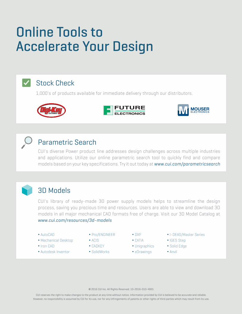
Online Tools to Accelerate Your Design
∆ AutoCAD∆ Mechanical Desktop∆ Iron CAD∆ Autodesk Inventor
Parametric Search CUI's diverse Power product line addresses design challenges across multiple industries and applications. Utilize our online parametric search tool to quickly find and compare models based on your key specifications. Try it out today at www.cui.com/parametricsearch
3D ModelsCUI's library of ready-made 3D power supply models helps to streamline the design process, saving you precious time and resources. Users are able to view and download 3D models in all major mechanical CAD formats free of charge. Visit our 3D Model Catalog at www.cui.com/resources/3d-models
Primary Logo Secondary Stacked Logo
Stock Check1,000's of products available for immediate delivery through our distributors.
∆ Pro/ENGINEER∆ ACIS∆ CADKEY∆ SolidWorks
∆ DXF∆ CATIA∆ Unigraphics∆ eDrawings
∆ I-DEAS/Master Series∆ IGES Step∆ Solid Edge∆ Anvil
© 2016 CUI Inc. All Rights Reserved. 10-2016-010-4001
CUI reserves the right to make changes to the product at any time without notice. Information provided by CUI is believed to be accurate and reliable.However, no responsibility is assumed by CUI for its use, nor for any infringements of patents or other rights of third parties which may result from its use.