Embed Size (px)
Citation preview
24/7/1437
dc-dc
converter Power electronics devices
Supervisor doctor: MOHAMMED T. LAZIM
Professor of Electrical and Electronics Engineering
Electrical Engineering Department
Philadelphia University, Jordan
Student name:moaz mh zafer al hosny
Student number:201310175
1
DC CHOPPERS INTRODUCTION
A chopper is a static device which is used to obtain a variable dc voltage from a
constant dc voltage source. A chopper is also known as dc-to-dc converter. The
thyristor converter offers greater efficiency, faster response, lower maintenance,
smaller size and smooth control. Choppers are widely used in trolley cars, battery
operated vehicles, traction motor control, control of large number of dc motors,
etc….. They are also used in regenerative braking of dc motors to return energy back
to supply and also as dc voltage regulators.
Choppers are of two types
• Step-down choppers
• Step-up choppers.
In step-down choppers, the output voltage will be less than the input voltage
whereas in step-up choppers output voltage will be more than the input voltage.
Classification of Choppers:
(a) Depending upon the direction of the output current and voltage, the
converters can be classified into five classes namely
Class A [One-quadrant Operation]
Class B [One-quadrant Operation]
Class C [Two-quadrant Operation]
Class D [Two-quadrant Operation]
Class E [Four-quadrant Operation]
(b) Based on the output voltage of the output, the choppers are classified as
(i) Step-Down Chopper
In this case the average output voltage is less than the input voltage. It is also known
as step down converter
(ii) Step-Up Chopper
Here the average output voltage is more than the input voltage. It is also known as
step up converter
(iii) Step-Up/Down Chopper
This type of converter produces an output voltage that is either lower or higher than
the input voltage
(c) Depending upon the power loss occurred during turn ON/OFF of the switching
device, the choppers are classified into two categories namely
(i) Hard switched Converter
Here the power loss is high during the switching (ON to OFF and OFF to ON) as a
result of the non zero voltage and current on the power switches.
(ii) Soft switched or resonant converters
In this type of choppers, the power loss is low at the time of switching as a result of
zero voltage and/or zero current on the switches.
2
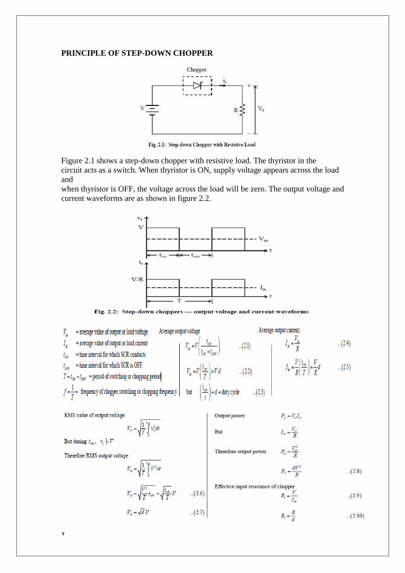
PRINCIPLE OF STEP-DOWN CHOPPER
Figure 2.1 shows a step-down chopper with resistive load. The thyristor in the
circuit acts as a switch. When thyristor is ON, supply voltage appears across the load
and
when thyristor is OFF, the voltage across the load will be zero. The output voltage and
current waveforms are as shown in figure 2.2.

3
The output voltage can be varied by varying the duty cycle.
METHODS OF CONTROL:
pulse width modulation
In pulse width modulation the pulse width of the output waveform is varied
keeping chopping frequency ‘f’ and hence chopping period ‘T’ constant. Therefore
output voltage is varied by varying the ON time, Figure 2.3 shows the output
voltage waveforms for different ON times.
VARIABLE FREQUENCY CONTROL
In this method of control, chopping frequency f is varied keeping either ton or
Toff constant. This method is also known as frequency modulation.
Figure 2.4 shows the output voltage waveforms for a constant ton and variable
chopping period T.
In frequency modulation to obtain full output voltage, range frequency has to be
varied over a wide range. This method produces harmonics in the output and for large
toff load current may become discontinuous.
STEP-DOWN CHOPPER WITH R-L LOAD
Figure 2.5 shows a step-down chopper with R-L load and free wheeling diode.
When chopper is ON, the supply is connected across the load. Current flows from the
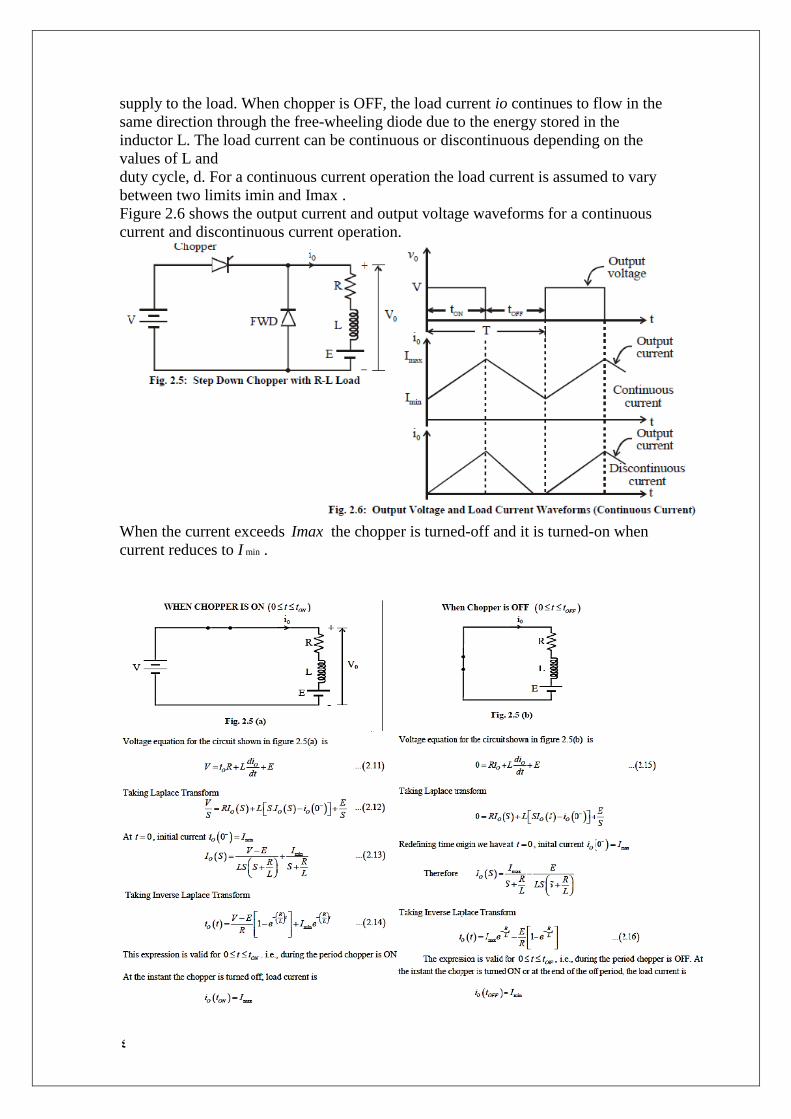
4
supply to the load. When chopper is OFF, the load current io continues to flow in the
same direction through the free-wheeling diode due to the energy stored in the
inductor L. The load current can be continuous or discontinuous depending on the
values of L and
duty cycle, d. For a continuous current operation the load current is assumed to vary
between two limits imin and Imax .
Figure 2.6 shows the output current and output voltage waveforms for a continuous
current and discontinuous current operation.
When the current exceeds Imax the chopper is turned-off and it is turned-on when
current reduces to I min .

5
PRINCIPLE OF STEP-UP CHOPPER
Figure 2.13 shows a step-up chopper to obtain a load voltage O V higher than the input
voltage V. The values of L and C are chosen depending upon the requirement of
output voltage and current. When the chopper is ON, the inductor L is connected
across the supply. The inductor current ‘I’ rises and the inductor stores energy during
the ON time of the chopper, ON t . When the chopper is off, the inductor current I is
forced to flow through the diode D and load for a period, TOFF . The current tends to
decrease resulting in reversing the polarity of induced EMF in L. Therefore voltage
across load is given by
If a large capacitor ‘C’ is connected across the load then the capacitor will provide

6
a continuous output voltage O V . Diode D prevents any current flow from capacitor to
the source. Step up choppers are used for regenerative braking of dc motors.
EXPRESSION FOR OUTPUT VOLTAGE
Assume the average inductor current to be I during ON and OFF time of Chopper.
When Chopper is ON
Voltage across inductor L =V
Therefore energy stored in inductor
PERFORMANCE PARAMETERS
The thyristor requires a certain minimum time to turn ON and turn OFF. Hence
duty cycle d can be varied only between a minimum and a maximum value, limiting
the minimum and maximum value of the output voltage. Ripple in the load current
depends inversely on the chopping frequency, f. Therefore to reduce the load ripple
current, frequency should be as high as possible.
CLASSIFICATION OF CHOPPERS
Choppers are classified as follows
• Class A Chopper
• Class B Chopper
• Class C Chopper
• Class D Chopper
• Class E Chopper
7
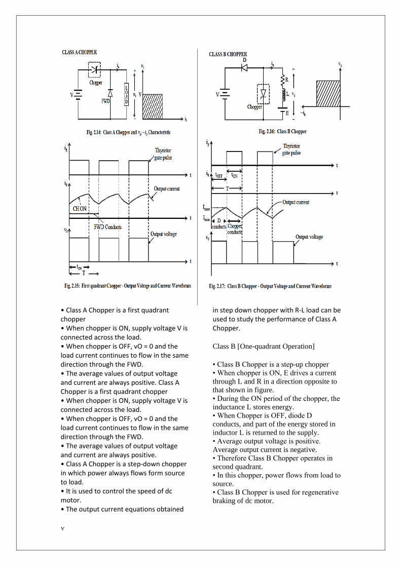
• Class A Chopper is a first quadrant chopper • When chopper is ON, supply voltage V is connected across the load. • When chopper is OFF, vO = 0 and the load current continues to flow in the same direction through the FWD. • The average values of output voltage and current are always positive. Class A Chopper is a first quadrant chopper • When chopper is ON, supply voltage V is connected across the load. • When chopper is OFF, vO = 0 and the load current continues to flow in the same direction through the FWD. • The average values of output voltage and current are always positive. • Class A Chopper is a step-down chopper in which power always flows form source to load. • It is used to control the speed of dc motor. • The output current equations obtained
in step down chopper with R-L load can be used to study the performance of Class A Chopper.
Class B [One-quadrant Operation]
• Class B Chopper is a step-up chopper
• When chopper is ON, E drives a current
through L and R in a direction opposite to
that shown in figure.
• During the ON period of the chopper, the
inductance L stores energy.
• When Chopper is OFF, diode D
conducts, and part of the energy stored in
inductor L is returned to the supply.
• Average output voltage is positive.
Average output current is negative.
• Therefore Class B Chopper operates in
second quadrant.
• In this chopper, power flows from load to
source.
• Class B Chopper is used for regenerative
braking of dc motor.
8
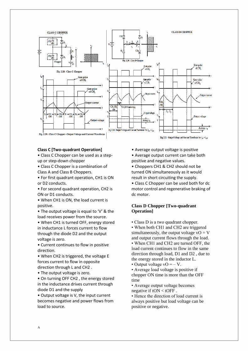
Class C [Two-quadrant Operation] • Class C Chopper can be used as a step-up or step-down chopper • Class C Chopper is a combination of Class A and Class B Choppers. • For first quadrant operation, CH1 is ON or D2 conducts. • For second quadrant operation, CH2 is ON or D1 conducts. • When CH1 is ON, the load current is positive. • The output voltage is equal to ‘V’ & the load receives power from the source. • When CH1 is turned OFF, energy stored in inductance L forces current to flow through the diode D2 and the output voltage is zero. • Current continues to flow in positive direction. • When CH2 is triggered, the voltage E forces current to flow in opposite direction through L and CH2 . • The output voltage is zero. • On turning OFF CH2 , the energy stored in the inductance drives current through diode D1 and the supply • Output voltage is V, the input current becomes negative and power flows from load to source.
• Average output voltage is positive • Average output current can take both positive and negative values. • Choppers CH1 & CH2 should not be turned ON simultaneously as it would result in short circuiting the supply. • Class C Chopper can be used both for dc motor control and regenerative braking of dc motor.
Class D Chopper [Two-quadrant
Operation]
• Class D is a two quadrant chopper.
• When both CH1 and CH2 are triggered
simultaneously, the output voltage vO = V
and output current flows through the load.
• When CH1 and CH2 are turned OFF, the
load current continues to flow in the same
direction through load, D1 and D2 , due to
the energy stored in the inductor L.
• Output voltage vO = – V.
• Average load voltage is positive if
chopper ON time is more than the OFF
time
• Average output voltage becomes
negative if tON < tOFF .
• Hence the direction of load current is
always positive but load voltage can be
positive or negative.
9
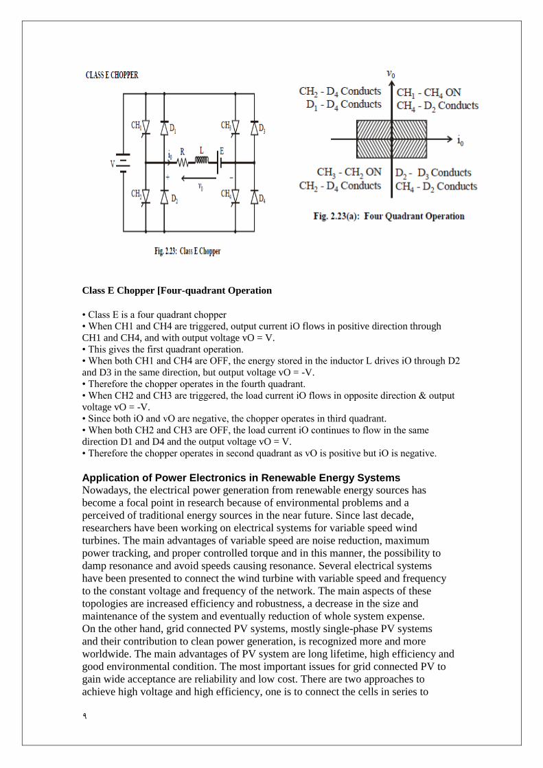
Class E Chopper [Four-quadrant Operation
• Class E is a four quadrant chopper
• When CH1 and CH4 are triggered, output current iO flows in positive direction through
CH1 and CH4, and with output voltage vO = V.
• This gives the first quadrant operation.
• When both CH1 and CH4 are OFF, the energy stored in the inductor L drives iO through D2
and D3 in the same direction, but output voltage vO = -V.
• Therefore the chopper operates in the fourth quadrant.
• When CH2 and CH3 are triggered, the load current iO flows in opposite direction & output
voltage vO = -V.
• Since both iO and vO are negative, the chopper operates in third quadrant.
• When both CH2 and CH3 are OFF, the load current iO continues to flow in the same
direction D1 and D4 and the output voltage vO = V.
• Therefore the chopper operates in second quadrant as vO is positive but iO is negative.
Application of Power Electronics in Renewable Energy Systems Nowadays, the electrical power generation from renewable energy sources has
become a focal point in research because of environmental problems and a
perceived of traditional energy sources in the near future. Since last decade,
researchers have been working on electrical systems for variable speed wind
turbines. The main advantages of variable speed are noise reduction, maximum
power tracking, and proper controlled torque and in this manner, the possibility to
damp resonance and avoid speeds causing resonance. Several electrical systems
have been presented to connect the wind turbine with variable speed and frequency
to the constant voltage and frequency of the network. The main aspects of these
topologies are increased efficiency and robustness, a decrease in the size and
maintenance of the system and eventually reduction of whole system expense.
On the other hand, grid connected PV systems, mostly single-phase PV systems
and their contribution to clean power generation, is recognized more and more
worldwide. The main advantages of PV system are long lifetime, high efficiency and
good environmental condition. The most important issues for grid connected PV to
gain wide acceptance are reliability and low cost. There are two approaches to
achieve high voltage and high efficiency, one is to connect the cells in series to
11
generate high voltage DC and use high voltage DC to an AC inverter circuit.
However, this configuration needs high voltage rate devices for the inverter. Another
approach is to use low voltage devices for the inverter and then step up the voltage
using transformers. This can increase losses and cost of system. Using
transformerless concepts are advantageous with regard to their high efficiency and
the resulting benefits of reduction in cost, size, weight and complexity of the inverter.
Another renewable energy source is FC which are considered attractive for
Distributed Generation (DG) applications. Fuel cells are electrochemical devices that
convert the chemical energy of fuel and oxidant directly to electrical energy and heat.
In fuel cell powered applications, a fuel cell (low power) will supply the system, then
a DC-DC converter is used to boost the low voltage of the fuel cell to make a high
voltage DC link. A DC-AC inverter is used to obtain AC voltage to feed the load.
List of applications:
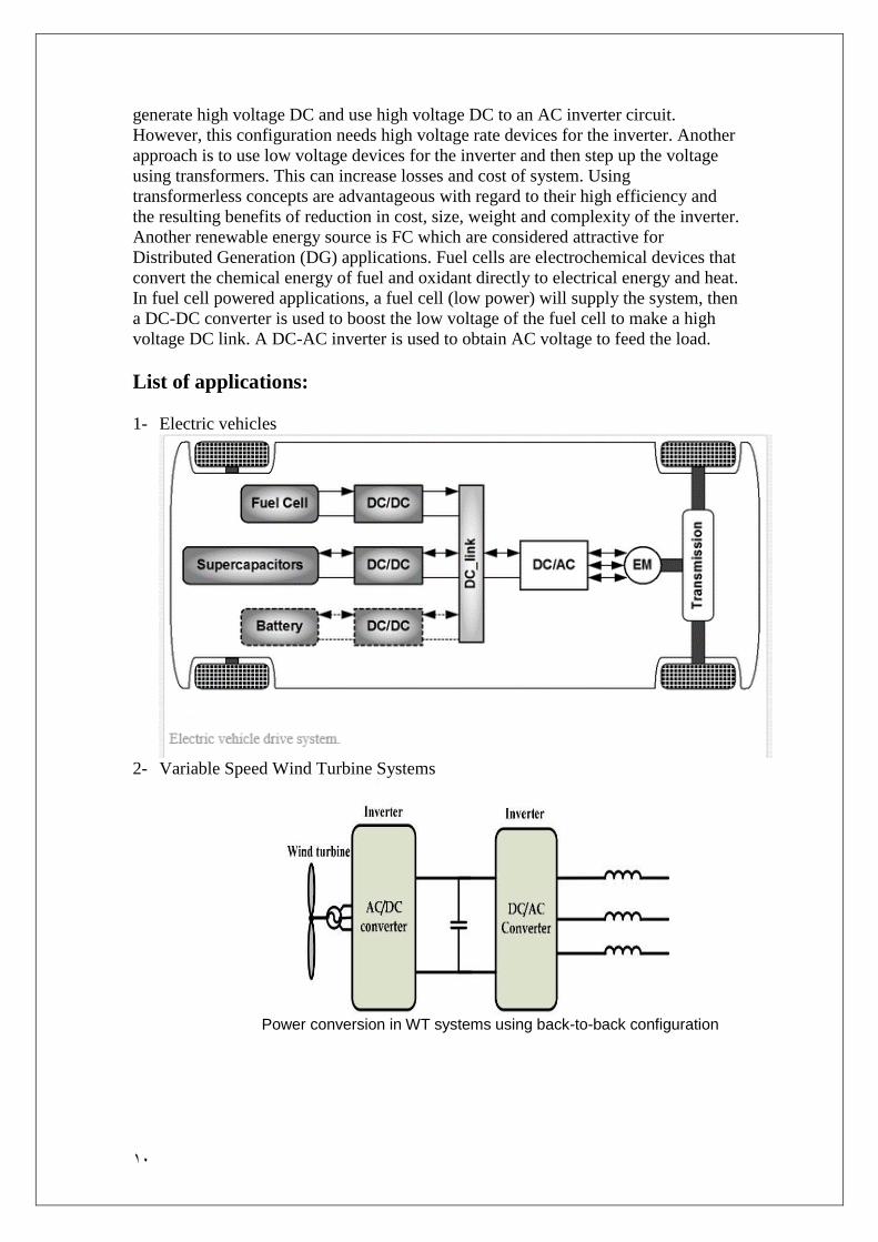
1- Electric vehicles
2- Variable Speed Wind Turbine Systems
Power conversion in WT systems using back-to-back configuration

11
Power conversion in WT systems using rectifier and step-up converter 3- Photovoltaic and Fuel Cell Systems
Power conversion in transformerless PV systems
Multilevel converter intransformerless PV systems
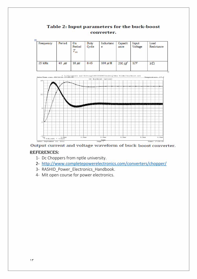
SIMULATION RESULTS OF DC-DC CONVERTERS on PSpice
Circuit for the simulation of buck converter
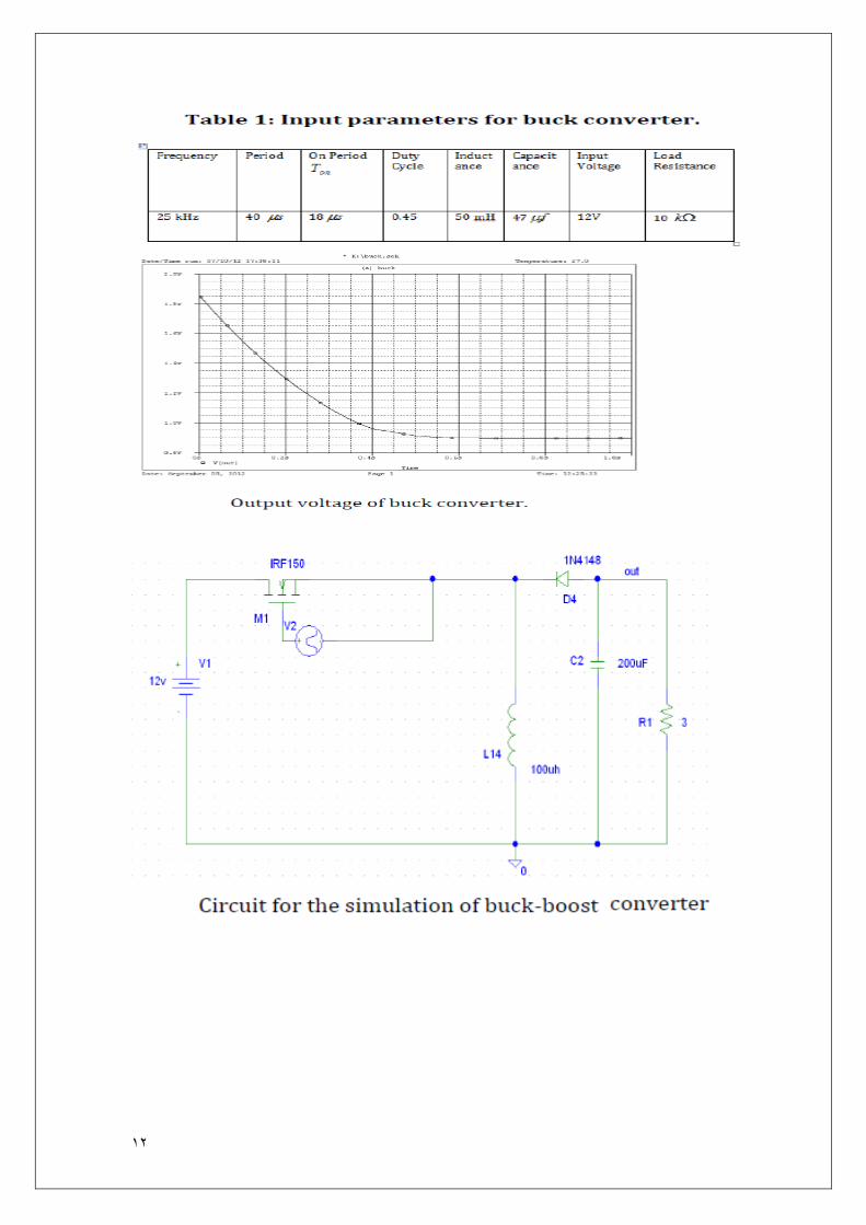
12
13
References: 1- Dc Choppers from nptle university. 2- http://www.completepowerelectronics.com/converters/chopper/ 3- RASHID_Power_Electronics_Handbook. 4- Mit open course for power electronics.