Embed Size (px)
Citation preview
http://www.iaeme.com/IJMET/index.asp 213 [email protected]
International Journal of Mechanical Engineering and Technology (IJMET) Volume 6, Issue 11, Nov 2015, pp. 213-228, Article ID: IJMET_06_11_024
Available online at
http://www.iaeme.com/IJMET/issues.asp?JTypeIJMET&VType=6&IType=11
ISSN Print: 0976-6340 and ISSN Online: 0976-6359
© IAEME Publication
PERFORMANCE EVALUATION OF A
DIESEL ENGINE RUNNING IN DUAL FUEL
MODE WITH KARANJA BIO DIESEL
(KOME) & LIQUIFIED PETROLEUM GAS
(LPG)
Chanderbhan Singh Tomar
Research Scholar (PG), Department of Mechanical Engineering,
University Institute of Technology,
Rajiv Gandhi Prodyogiki Vishwavidyalaya, Bhopal, Madhya Pradesh, India
Ravindra Randa
Assistant Professor, Department of Mechanical Engineering,
University Institute of Technology,
Rajiv Gandhi Prodyogiki Vishwavidyalaya, Bhopal, Madhya Pradesh, India
Suraj Dev Singh
Research Scholar (PG), Department of Mechanical Engineering,
University Institute of Technology,
Rajiv Gandhi Prodyogiki Vishwavidyalaya, Bhopal, Madhya Pradesh, India
ABSTRACT
Present study shows utilisation of LPG in CI engine with Bio diesel in dual
fuel mode. For this experimental work a stationary, single cylinder, four
stroke diesel engine was used with few attachments. Major performance
parameters such as Brake power, Brake thermal efficiency, Brake specific fuel
consumption etc. were evaluated at different loads and with different fuel
combinations . up to 12% biodiesel was saved in dual fuel mode & up to 40%
improvements were evident in Brake specific fuel consumption, whereas
break thermal efficiency did not improve due to poor utilization of high energy
content of LPG. The cost incurred for making Biodiesel was huge and
disappointing but if it is promoted by government and made on a large scale,
it would definitely prove itself as an affordable fuel. The concept of present
work of mixing biodiesel and LPG for operating diesel engine can be
employed to make more technologically subtle & advance engines that could
run smoothly on dual fuel and harness their full potential.
Key words: C.I. Engine; Biodiesel; Karanja Oil Methyl Ester; Dual Fuel Etc.
Chanderbhan Singh Tomar, Ravindra Randa and Suraj Dev Singh
http://www.iaeme.com/IJMET/index.asp 214 [email protected]
Cite this Article: Chanderbhan Singh Tomar, Ravindra Randa and Suraj Dev
Singh, Performance Evaluation of A Diesel Engine Running In Dual Fuel Mode
with Karanja Bio Diesel (Kome) & Liquified Petroleum Gas (LPG).
International Journal of Mechanical Engineering and Technology, 6(11), 2015,
pp. 213-228.
http://www.iaeme.com/currentissue.asp?JType=IJMET&VType=6&IType=11
1. INTRODUCTION
In today’s scenario, the most challenging global issues are Energy security and
Environmental concerns caused due to burning of Fossil fuels. Today, the whole
world relies heavily on Fossil fuel reserves which are limited and depleting
rapidly.Global oil supplies may peak in the next few decades and oil prices could rise
dramatically. Significantly higher energy prices would adversely affect economic
growth and complicate poverty reduction efforts in developing countries like
India.(1)
Research are going all over the world for finding a suitable, sustainable, non-
polluting and renewable source of energy which can fulfil the energy demand of
world. Bio-fuels have come up as a promising alternative and intensive research are
going on for more refined bio fuels having higher calorific value, lesser harmful
emissions and smoother running engines. Several research are being carried on for
finding suitable mixes of bio fuels, bio fuels with other fuels such gas CNG, LPG, Bio
gas etc. to replace their lower calorific value deficiency. The Bio fuels may be
considered green as the emission produced by them is filtered during their lifecycle.
Bio fuels offer an attractive option for meeting part of India’s energy needs. Bio fuels,
in theory, can be produced from a wide variety of domestic feedstock. Like solar or
wind power, bio fuels are considered renewable energy sources as they rely on plant
or waste products. This paper deals with biodiesel & LPG, a subset of bio fuels along
with a Fossil gas that can substitute for petroleum diesel. Many universities across the
world are running research programs in the field of renewable energy to promote and
fight the coming up energy scarcity of world. Bio fuels are affordable substitutes for
imported fossil fuels, generate rural income and employment, and reduce GHG
emissions. But they also compete for agricultural resources, and this competition may
seriously undermine food security. For India, with its growing population and fixed
amount of arable lands, food security is a prime concern. India’s bio fuels policy
clearly states that energy crop production should not be promoted at the cost of the
food sector. Biodiesel produced from non edible oilseeds cultivated on wasteland or
fallow land gives India an opportunity to enhance its energy security without
compromising food security.
In this paper, we are using a non edible oil (Pongamia Pinnata oil) made biodiesel
along with the LPG to run a conventional Diesel engine with few modifications. India
relies heavily on imported oil to fuel its rapidly growing economy. The country’s
reserves of fossil fuels are limited. Petroleum imports in the last few years ran nearly
four times domestic production.(2)
This dependency is likely to increase. India’s per
capita energy consumption was roughly one-quarter of the global average, a figure
that will only increase with a rising standard of living.(3)
This leaves the country
vulnerable to price shocks when oil prices rise on global markets.
Biodiesel production in India is a special case which has much more positive
development effects than biodiesel production elsewhere. India is different because
there is far-reaching consensus there that biodiesel production will only be promoted
on the basis of non-edible oil seeds on marginal lands. Hence the risks of driving up
Performance Evaluation of A Diesel Engine Running In Dual Fuel Mode with Karanja Bio
Diesel (Kome) & Liquified Petroleum Gas (LPG)
http://www.iaeme.com/IJMET/index.asp 215 [email protected]
prices for edible oil or crowding out food production are relatively low. In addition,
cultivating tree-borne oilseeds on degraded lands stabilizes soils and creates carbon
sinks, and production requires low inputs, which serves to further improve the carbon
balance.
Methods for converting a diesel engine to consume alternative fuels typically fall
into three categories. The first is to convert the engine to a spark-ignited engine; a
second is to convert the engine to allow for the direct injection of gaseous-fuels into
the combustion chamber; and a third is "fogging" or "fumigation" of the gaseous-fuel
with all or a portion of the intake air charge entering the engine.
In our experiment, we will be using this method of fumigation to run the governor
controlled constant speed diesel engine in dual fuel mode using Karanja Bio Diesel
and LPG. In this method, the mixture of gaseous-fuel with the intake air charge is
introduced into each cylinder of the engine during the intake stroke. During the
compression stroke of the piston, the pressure and temperature of the mixture are
increased in the conventional manner. Near the end of the compression stroke, a
smaller than normal quantity of diesel fuel from the engine's existing diesel fuel
injection system is injected into the cylinder. The diesel ignites due to compression
and in turn ignites the mixture of gaseous-fuel and intake air, which in turn,
accelerates the flame front of the Diesel Fuel, enhancing the combustion process. For
the purpose, we have attached a convergent divergent steel nozzle in the path of air
supply to combustion chamber and made a very small hole at the throat of nozzle to
accommodate the gas welding torch tip for supplying LPG during operating the
engine. The supply of LPG has been kept constant, only the Load on the engine has
been changed and performances were observed. Bio-Diesel poses to be a promising
fuel for future and mixing LPG with it gives it the desired power which seems to be
lacking with biodiesel alone, also the LPG helps to burn the fuel completely and
therefore reduces emissions and helps to harness the overall energy contained in the
fuel. Furthermore, engines using such fumigation systems may typically be operated
in a dual-fuel mode or in a strictly diesel mode (e.g., when gaseous-fuel is not
available). (4)
Table 1 Comparison between properties of Karanja biodiesel and LPG:-
PROPERTIES KOME
BIODIESEL(8)
LPG
(6,7) DIESEL
(5,8)
Normal State LIQUID GASEOUS LIQUID
Calorific Value(Kj/Kg) 37580 LHV: 46350
HHV: 50350
LHV: 43400
HHV: 44800
Density(Kg/M3) 891.8
525-580(liquid)
1.888-2.45(gaseous) 820-950
Specific Gravity(Relative To Water) 0.891 0.525-O.580(liquid) 0.82-0.95
Flash Point(0c) 136 -104 62
KINEMATIC VISCOSITY, Cst 5.5 --- 2.4
Fire Point(0c) 223 63
Auto Ignition Temperature(0c)
-- 410-580 176.4 TO 329.44
Cetane Number 05-10 40-60
Stichiometric A/F Ratio (Mass) -- 15.7 14.5
Peak Flame Temperature(0c) -- 1990 2054
Boiling Point(0c) -42 149-371
Chanderbhan Singh Tomar, Ravindra Randa and Suraj Dev Singh
http://www.iaeme.com/IJMET/index.asp 216 [email protected]
It is clear from the table that LPG has a quite low Cetane number which makes it
inefficient for self ignition, that’s why a small quantity of Bio Diesel known as pilot
fuel is to be supplied to provoke ignition in the combustion chamber. The rest of
power is supplied by the combustion of LPG. And since LPG has a grater Calorific
value, its combustion facilitates in providing required or greater power consuming a
lesser quantity of fuel thus improving the fuel economy.
With Dual Fuel operation, there is no change to the basic architecture of the diesel
engine – or to the principle of diesel combustion. The engine itself is virtually
unaltered, but for the addition of a gas injection system. The Dual-Fuel in-cylinder
temperatures and pressures remain within the limits of pure diesel operation, so the
converted engine operates within the parameters of the original engine In a Dual-Fuel
engine, however, the diesel fuel injector works like a liquid spark plug. Highly
pressurized, it ignites a mixture of compressed gas and air in the cylinder.
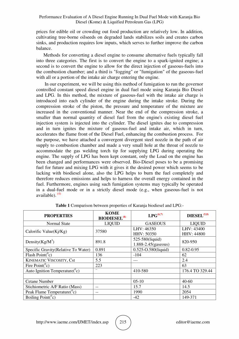
2. SPECIFICATIONS OF THE TEST ENGINE
The engine used in this experiment is installed at University Institute of Technology,
Rajiv Gandhi Technical University, Bhopal. The RGPV engine test contains a
complete system for measuring all the parameters relating to the diesel engine
performance analysis. The experimental set-up contains mainly a dynamometer to
load the engine. Figure below gives a diagram of the experimental system used.
Figure 1 Diesel Engine Test Rig Showing Dynamometer
Performance Evaluation of A Diesel Engine Running In Dual Fuel Mode with Karanja Bio
Diesel (Kome) & Liquified Petroleum Gas (LPG)
http://www.iaeme.com/IJMET/index.asp 217 [email protected]
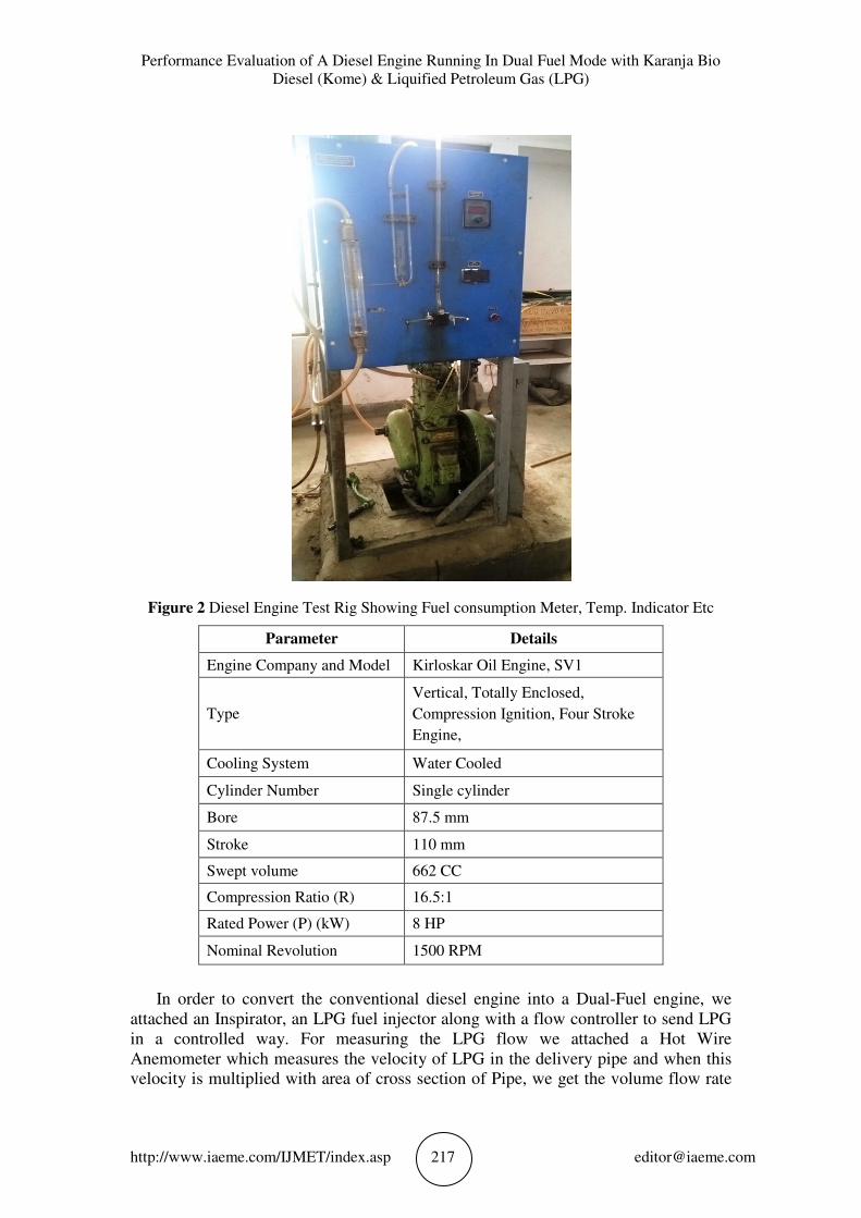
Figure 2 Diesel Engine Test Rig Showing Fuel consumption Meter, Temp. Indicator Etc
Parameter Details
Engine Company and Model Kirloskar Oil Engine, SV1
Type
Vertical, Totally Enclosed,
Compression Ignition, Four Stroke
Engine,
Cooling System Water Cooled
Cylinder Number Single cylinder
Bore 87.5 mm
Stroke 110 mm
Swept volume 662 CC
Compression Ratio (R) 16.5:1
Rated Power (P) (kW) 8 HP
Nominal Revolution 1500 RPM
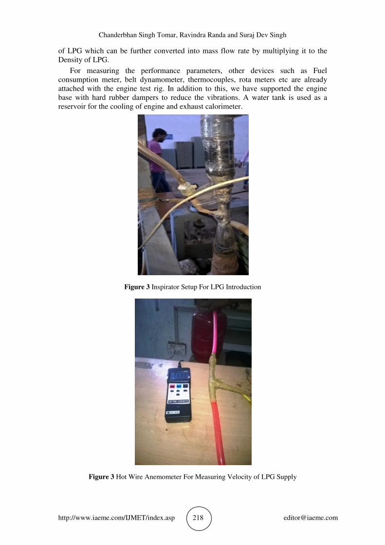
In order to convert the conventional diesel engine into a Dual-Fuel engine, we
attached an Inspirator, an LPG fuel injector along with a flow controller to send LPG
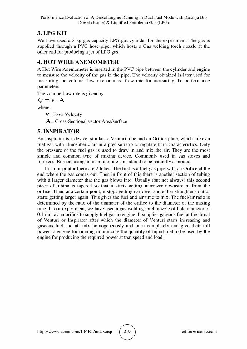
in a controlled way. For measuring the LPG flow we attached a Hot Wire
Anemometer which measures the velocity of LPG in the delivery pipe and when this
velocity is multiplied with area of cross section of Pipe, we get the volume flow rate
Chanderbhan Singh Tomar, Ravindra Randa and Suraj Dev Singh
http://www.iaeme.com/IJMET/index.asp 218 [email protected]
of LPG which can be further converted into mass flow rate by multiplying it to the
Density of LPG.
For measuring the performance parameters, other devices such as Fuel
consumption meter, belt dynamometer, thermocouples, rota meters etc are already
attached with the engine test rig. In addition to this, we have supported the engine
base with hard rubber dampers to reduce the vibrations. A water tank is used as a
reservoir for the cooling of engine and exhaust calorimeter.
Figure 3 Inspirator Setup For LPG Introduction
Figure 3 Hot Wire Anemometer For Measuring Velocity of LPG Supply
Performance Evaluation of A Diesel Engine Running In Dual Fuel Mode
Diesel (Kome) & Liquified Petroleum Gas (
http://www.iaeme.com/IJMET/index.asp
3. LPG KIT
We have used a 3 kg gas capacity LPG gas cylinder for the
supplied through a PVC hose pipe, which hosts a Gas welding torch nozzle at the
other end for producing a jet of LPG gas.
4. HOT WIRE ANEMOMETER
A Hot Wire Anemometer is inserted in the PVC pipe between the cylinder and engine
to measure the velocity of the gas in the pipe. The velocity obtained is later used for
measuring the volume flow rate or mass flow rate for measuring the performance
parameters.
The volume flow rate is given by
where:
= Flow Velocity
= Cross-Sectional ve
5. INSPIRATOR
An Inspirator is a device, similar to Venturi tube and an Orifice plate, which mixes a
fuel gas with atmospheric air in a precise ratio to regulate burn characteristics. Only
the pressure of the fuel gas is used to draw in
simple and common type of mixing device. Commonly used in gas stoves and
furnaces. Burners using an inspirator are considered to be naturally aspirated.
In an inspirator there are 2 tubes. The first is a fuel gas pipe wit
end where the gas comes out. Then in front of this there is another section of tubing
with a larger diameter that the gas blows into. Usually (but not always) this second
piece of tubing is tapered so that it starts getting narrower dow
orifice. Then, at a certain point, it stops getting narrower and either straightens out or
starts getting larger again. This gives the fuel and air time to mix. The fuel/air ratio is
determined by the ratio of the diameter of the orifice t
tube. In our experiment, we have used a gas welding torch nozzle of hole
0.1 mm as an orifice to supply fuel gas to engine. It supplies gaseous fuel at the throat
of Venturi or Inspirator after which the dia
gaseous fuel and air mix homogeneously and burn completely and give their full
power to engine for running minimizing the quantity of liquid fuel to be used by the
engine for producing the required power at that speed and
f A Diesel Engine Running In Dual Fuel Mode with Karanja Bio
Diesel (Kome) & Liquified Petroleum Gas (LPG)
http://www.iaeme.com/IJMET/index.asp 219
e have used a 3 kg gas capacity LPG gas cylinder for the experiment. The gas is
supplied through a PVC hose pipe, which hosts a Gas welding torch nozzle at the
other end for producing a jet of LPG gas.
HOT WIRE ANEMOMETER
A Hot Wire Anemometer is inserted in the PVC pipe between the cylinder and engine
easure the velocity of the gas in the pipe. The velocity obtained is later used for
measuring the volume flow rate or mass flow rate for measuring the performance
The volume flow rate is given by
Sectional vector Area/surface
is a device, similar to Venturi tube and an Orifice plate, which mixes a
fuel gas with atmospheric air in a precise ratio to regulate burn characteristics. Only
the pressure of the fuel gas is used to draw in and mix the air. They are the most
simple and common type of mixing device. Commonly used in gas stoves and
furnaces. Burners using an inspirator are considered to be naturally aspirated.
In an inspirator there are 2 tubes. The first is a fuel gas pipe with an Orifice at the
end where the gas comes out. Then in front of this there is another section of tubing
with a larger diameter that the gas blows into. Usually (but not always) this second
piece of tubing is tapered so that it starts getting narrower downstream from the
orifice. Then, at a certain point, it stops getting narrower and either straightens out or
starts getting larger again. This gives the fuel and air time to mix. The fuel/air ratio is
determined by the ratio of the diameter of the orifice to the diameter of the mixing
tube. In our experiment, we have used a gas welding torch nozzle of hole
0.1 mm as an orifice to supply fuel gas to engine. It supplies gaseous fuel at the throat
of Venturi or Inspirator after which the diameter of Venturi starts increasing and
gaseous fuel and air mix homogeneously and burn completely and give their full
power to engine for running minimizing the quantity of liquid fuel to be used by the
engine for producing the required power at that speed and load.
ith Karanja Bio
experiment. The gas is
supplied through a PVC hose pipe, which hosts a Gas welding torch nozzle at the
A Hot Wire Anemometer is inserted in the PVC pipe between the cylinder and engine
easure the velocity of the gas in the pipe. The velocity obtained is later used for
measuring the volume flow rate or mass flow rate for measuring the performance
is a device, similar to Venturi tube and an Orifice plate, which mixes a
fuel gas with atmospheric air in a precise ratio to regulate burn characteristics. Only
and mix the air. They are the most
simple and common type of mixing device. Commonly used in gas stoves and
furnaces. Burners using an inspirator are considered to be naturally aspirated.
h an Orifice at the
end where the gas comes out. Then in front of this there is another section of tubing
with a larger diameter that the gas blows into. Usually (but not always) this second
nstream from the
orifice. Then, at a certain point, it stops getting narrower and either straightens out or
starts getting larger again. This gives the fuel and air time to mix. The fuel/air ratio is
o the diameter of the mixing
tube. In our experiment, we have used a gas welding torch nozzle of hole diameter of
0.1 mm as an orifice to supply fuel gas to engine. It supplies gaseous fuel at the throat
of Venturi starts increasing and
gaseous fuel and air mix homogeneously and burn completely and give their full
power to engine for running minimizing the quantity of liquid fuel to be used by the
Chanderbhan Singh Tomar, Ravindra Randa and Suraj Dev Singh
http://www.iaeme.com/IJMET/index.asp 220 [email protected]
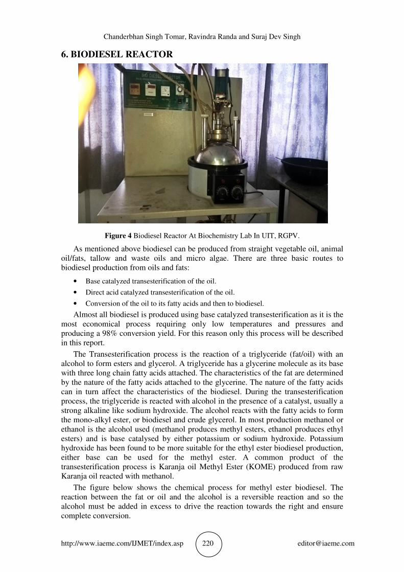
6. BIODIESEL REACTOR
Figure 4 Biodiesel Reactor At Biochemistry Lab In UIT, RGPV.
As mentioned above biodiesel can be produced from straight vegetable oil, animal
oil/fats, tallow and waste oils and micro algae. There are three basic routes to
biodiesel production from oils and fats:
• Base catalyzed transesterification of the oil.
• Direct acid catalyzed transesterification of the oil.
• Conversion of the oil to its fatty acids and then to biodiesel.
Almost all biodiesel is produced using base catalyzed transesterification as it is the
most economical process requiring only low temperatures and pressures and
producing a 98% conversion yield. For this reason only this process will be described
in this report.
The Transesterification process is the reaction of a triglyceride (fat/oil) with an
alcohol to form esters and glycerol. A triglyceride has a glycerine molecule as its base
with three long chain fatty acids attached. The characteristics of the fat are determined
by the nature of the fatty acids attached to the glycerine. The nature of the fatty acids
can in turn affect the characteristics of the biodiesel. During the transesterification
process, the triglyceride is reacted with alcohol in the presence of a catalyst, usually a
strong alkaline like sodium hydroxide. The alcohol reacts with the fatty acids to form
the mono-alkyl ester, or biodiesel and crude glycerol. In most production methanol or
ethanol is the alcohol used (methanol produces methyl esters, ethanol produces ethyl
esters) and is base catalysed by either potassium or sodium hydroxide. Potassium
hydroxide has been found to be more suitable for the ethyl ester biodiesel production,
either base can be used for the methyl ester. A common product of the
transesterification process is Karanja oil Methyl Ester (KOME) produced from raw
Karanja oil reacted with methanol.
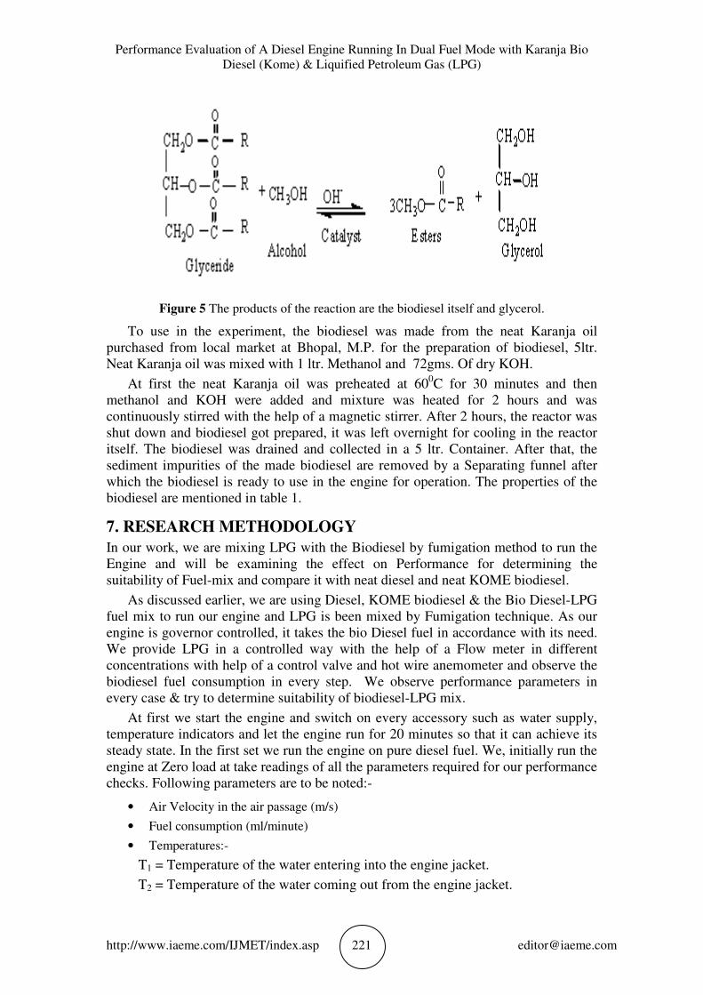
The figure below shows the chemical process for methyl ester biodiesel. The
reaction between the fat or oil and the alcohol is a reversible reaction and so the
alcohol must be added in excess to drive the reaction towards the right and ensure
complete conversion.
Performance Evaluation of A Diesel Engine Running In Dual Fuel Mode with Karanja Bio
Diesel (Kome) & Liquified Petroleum Gas (LPG)
http://www.iaeme.com/IJMET/index.asp 221 [email protected]
Figure 5 The products of the reaction are the biodiesel itself and glycerol.
To use in the experiment, the biodiesel was made from the neat Karanja oil
purchased from local market at Bhopal, M.P. for the preparation of biodiesel, 5ltr.
Neat Karanja oil was mixed with 1 ltr. Methanol and 72gms. Of dry KOH.
At first the neat Karanja oil was preheated at 600C for 30 minutes and then
methanol and KOH were added and mixture was heated for 2 hours and was
continuously stirred with the help of a magnetic stirrer. After 2 hours, the reactor was
shut down and biodiesel got prepared, it was left overnight for cooling in the reactor
itself. The biodiesel was drained and collected in a 5 ltr. Container. After that, the
sediment impurities of the made biodiesel are removed by a Separating funnel after
which the biodiesel is ready to use in the engine for operation. The properties of the
biodiesel are mentioned in table 1.
7. RESEARCH METHODOLOGY
In our work, we are mixing LPG with the Biodiesel by fumigation method to run the
Engine and will be examining the effect on Performance for determining the
suitability of Fuel-mix and compare it with neat diesel and neat KOME biodiesel.
As discussed earlier, we are using Diesel, KOME biodiesel & the Bio Diesel-LPG
fuel mix to run our engine and LPG is been mixed by Fumigation technique. As our
engine is governor controlled, it takes the bio Diesel fuel in accordance with its need.
We provide LPG in a controlled way with the help of a Flow meter in different
concentrations with help of a control valve and hot wire anemometer and observe the
biodiesel fuel consumption in every step. We observe performance parameters in
every case & try to determine suitability of biodiesel-LPG mix.
At first we start the engine and switch on every accessory such as water supply,
temperature indicators and let the engine run for 20 minutes so that it can achieve its
steady state. In the first set we run the engine on pure diesel fuel. We, initially run the
engine at Zero load at take readings of all the parameters required for our performance
checks. Following parameters are to be noted:-
• Air Velocity in the air passage (m/s)
• Fuel consumption (ml/minute)
• Temperatures:-
T1 = Temperature of the water entering into the engine jacket.
T2 = Temperature of the water coming out from the engine jacket.
Chanderbhan Singh Tomar, Ravindra Randa and Suraj Dev Singh
http://www.iaeme.com/IJMET/index.asp 222 [email protected]
T3 = Temperature of the Exhaust gases entering into the exhaust calorimeter.
T4 = Temperature of the Exhaust gases coming out from the exhaust calorimeter.
T5 = Temperature of the water entering into the Exhaust Calorimeter.
T6 = Temperature of water coming out from the Exhaust calorimeter.
1. Load on the engine applied by the Belt Dynamometer.(Kg.)
2. Water flow to the engine Jacket and To the Exhaust Calorimeter.(Liter per Minute)
3. After noting down all the parameters, we apply a load of 1 Kg on the engine and let it
run for 15 minutes to achieve the steady state and then point down all the parameters
again.
4. In the same manner, we increase the load to 2 kg than 4 kg and than 8 Kg and note
down all the parameters like before.
5. The results of the experiment are tabulated. These are our reference values.
6. The same was repeated with Neat Karanja Biodiesel.
7. In the next phase, we introduce LPG with the Bio Diesel and note down the readings.
In this stage,
8. We have to take reading of one additional parameter i.e. LPG fuel consumption. We
measure the LPG gas velocity with the help of a Hot Wire Anemometer and then
covert it into volume flow rate as discussed in earlier sections to measure its quantity
in m3/s or mass flow rate in Kg/s or Kg/hr.
9. After all the values are obtained, these values are scrutinized for the preparation of
final results and for comparing the performance parameters.
8. RESULTS AND DISCUSSION
The results are then tabulated and calculated thus for the results and then plotted in
the terms of line graphs. 5 different graphs have been plotted and discussed.
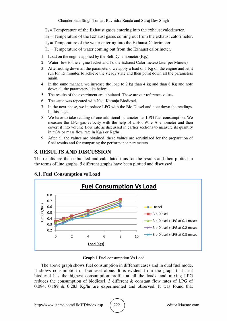
8.1. Fuel Consumption vs Load
Graph 1 Fuel consumption Vs Load
The above graph shows fuel consumption in different cases and in dual fuel mode,
it shows consumption of biodiesel alone. It is evident from the graph that neat
biodiesel has the highest consumption profile at all the loads, and mixing LPG
reduces the consumption of biodiesel. 3 different & constant flow rates of LPG of
0.094, 0.189 & 0.283 Kg/hr are experimented and observed. It was found that
0.2
0.3
0.4
0.5
0.6
0.7
0.8
0 2 4 6 8 10
F.C
. (K
g/h
r.)
Load (Kgs)
Fuel Consumption Vs Load
Diesel
Bio Diesel
Bio Diesel + LPG at 0.1 m/sec
Bio Diesel + LPG at 0.2 m/sec
Bio Diesel + LPG at 0.3 m/sec
Performance Evaluation of A Diesel Engine Running In Dual Fuel Mode with Karanja Bio
Diesel (Kome) & Liquified Petroleum Gas (LPG)
http://www.iaeme.com/IJMET/index.asp 223 [email protected]
biodiesel consumption was lowest in the case of LPG flow rate of 0.283 Kg/hr. at this
mode the biodiesel consumption at no load was 0.282 kg/hr. while the consumption in
case of neat biodiesel at no load was 0.357 kg/hr which is 0.075 kg/hr more than the
former. At full load, the consumption figure for dual fuel (LPG at 0.283 Kg/hr) was
0.642 kg/hr. while neat biodiesel was consumed at 0.730 kg/hr which is 0.088 kg/hr
more than former. Thus it is apparent that at high loads, dual fuel is more efficient.
Consumption of Neat diesel was lower than neat Biodiesel at all loads and at low
loads dual fuels were better than neat diesel but at higher loads diesel consumption
was the lowest than all other fuels and fuel combinations.
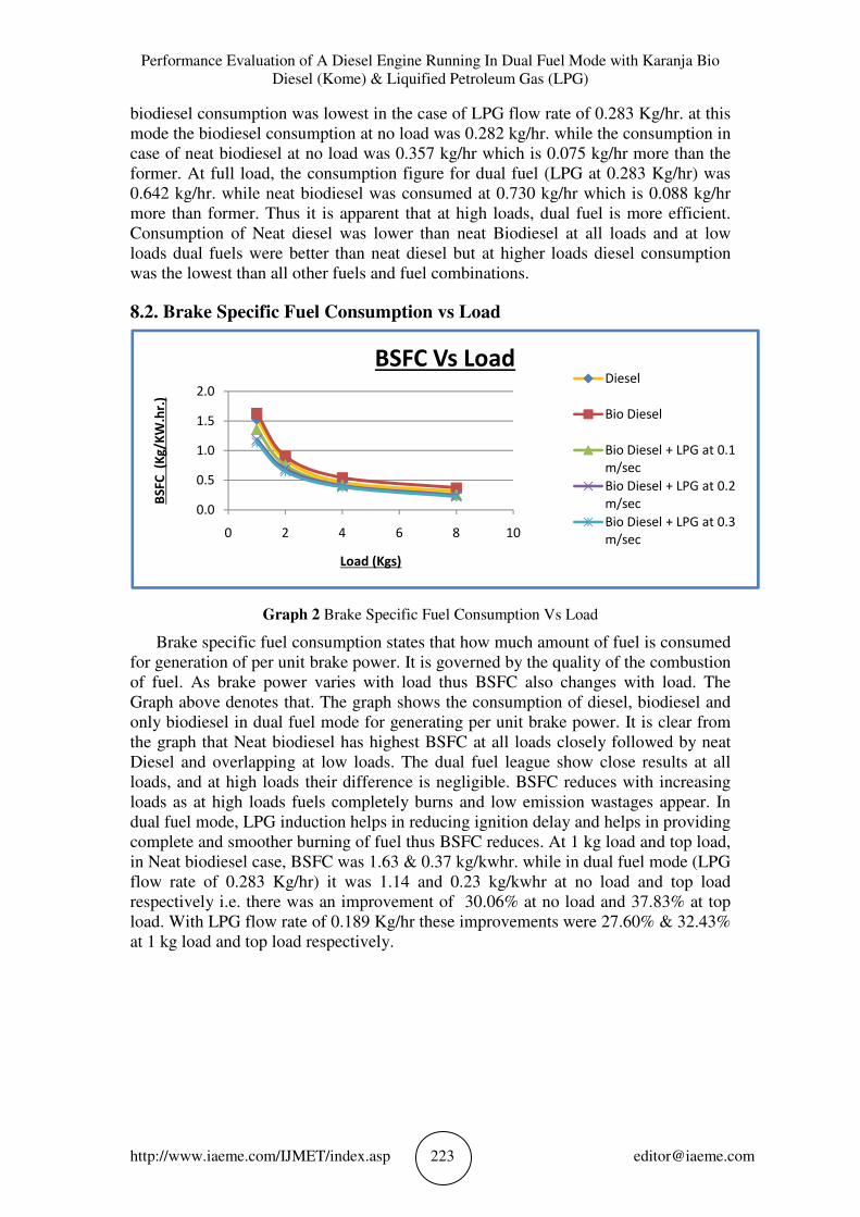
8.2. Brake Specific Fuel Consumption vs Load
Graph 2 Brake Specific Fuel Consumption Vs Load
Brake specific fuel consumption states that how much amount of fuel is consumed
for generation of per unit brake power. It is governed by the quality of the combustion
of fuel. As brake power varies with load thus BSFC also changes with load. The
Graph above denotes that. The graph shows the consumption of diesel, biodiesel and
only biodiesel in dual fuel mode for generating per unit brake power. It is clear from
the graph that Neat biodiesel has highest BSFC at all loads closely followed by neat
Diesel and overlapping at low loads. The dual fuel league show close results at all
loads, and at high loads their difference is negligible. BSFC reduces with increasing
loads as at high loads fuels completely burns and low emission wastages appear. In
dual fuel mode, LPG induction helps in reducing ignition delay and helps in providing
complete and smoother burning of fuel thus BSFC reduces. At 1 kg load and top load,
in Neat biodiesel case, BSFC was 1.63 & 0.37 kg/kwhr. while in dual fuel mode (LPG
flow rate of 0.283 Kg/hr) it was 1.14 and 0.23 kg/kwhr at no load and top load
respectively i.e. there was an improvement of 30.06% at no load and 37.83% at top
load. With LPG flow rate of 0.189 Kg/hr these improvements were 27.60% & 32.43%
at 1 kg load and top load respectively.
0.0
0.5
1.0
1.5
2.0
0 2 4 6 8 10
BS
FC
(K
g/K
W.h
r.)
Load (Kgs)
BSFC Vs LoadDiesel
Bio Diesel
Bio Diesel + LPG at 0.1
m/sec
Bio Diesel + LPG at 0.2
m/sec
Bio Diesel + LPG at 0.3
m/sec
Chanderbhan Singh Tomar, Ravindra Randa and Suraj Dev Singh
http://www.iaeme.com/IJMET/index.asp 224 [email protected]
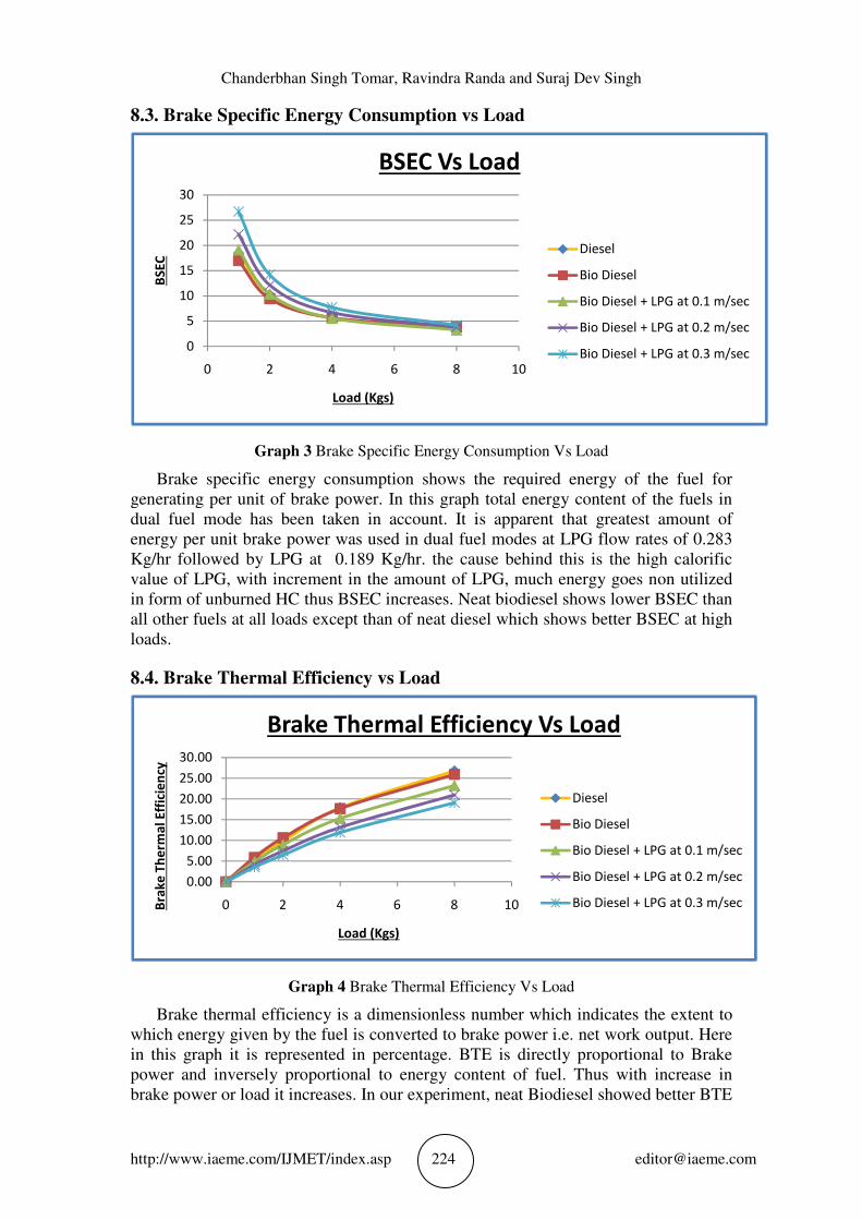
8.3. Brake Specific Energy Consumption vs Load
Graph 3 Brake Specific Energy Consumption Vs Load
Brake specific energy consumption shows the required energy of the fuel for
generating per unit of brake power. In this graph total energy content of the fuels in
dual fuel mode has been taken in account. It is apparent that greatest amount of
energy per unit brake power was used in dual fuel modes at LPG flow rates of 0.283
Kg/hr followed by LPG at 0.189 Kg/hr. the cause behind this is the high calorific
value of LPG, with increment in the amount of LPG, much energy goes non utilized
in form of unburned HC thus BSEC increases. Neat biodiesel shows lower BSEC than
all other fuels at all loads except than of neat diesel which shows better BSEC at high
loads.
8.4. Brake Thermal Efficiency vs Load
Graph 4 Brake Thermal Efficiency Vs Load
Brake thermal efficiency is a dimensionless number which indicates the extent to
which energy given by the fuel is converted to brake power i.e. net work output. Here
in this graph it is represented in percentage. BTE is directly proportional to Brake
power and inversely proportional to energy content of fuel. Thus with increase in
brake power or load it increases. In our experiment, neat Biodiesel showed better BTE
0
5
10
15
20
25
30
0 2 4 6 8 10
BS
EC
Load (Kgs)
BSEC Vs Load
Diesel
Bio Diesel
Bio Diesel + LPG at 0.1 m/sec
Bio Diesel + LPG at 0.2 m/sec
Bio Diesel + LPG at 0.3 m/sec
0.00
5.00
10.00
15.00
20.00
25.00
30.00
0 2 4 6 8 10Bra
ke
Th
erm
al
Eff
icie
ncy
Load (Kgs)
Brake Thermal Efficiency Vs Load
Diesel
Bio Diesel
Bio Diesel + LPG at 0.1 m/sec
Bio Diesel + LPG at 0.2 m/sec
Bio Diesel + LPG at 0.3 m/sec
Performance Evaluation of A Diesel Engine Running In Dual Fuel Mode with Karanja Bio
Diesel (Kome) & Liquified Petroleum Gas (LPG)
http://www.iaeme.com/IJMET/index.asp 225 [email protected]
just next to diesel which showed better BTE at all load among all fuels. With the
increment in the quantity of LPG, BTE reduces as total energy content of the fuel
increases. The poorest BTE thus, was observed in dual fuel mode with LPG flow rate
of 0.283 Kg/hr. higher calorific value of LPG fuel an its poor utilization inside
combustion chamber reduces the BTE.
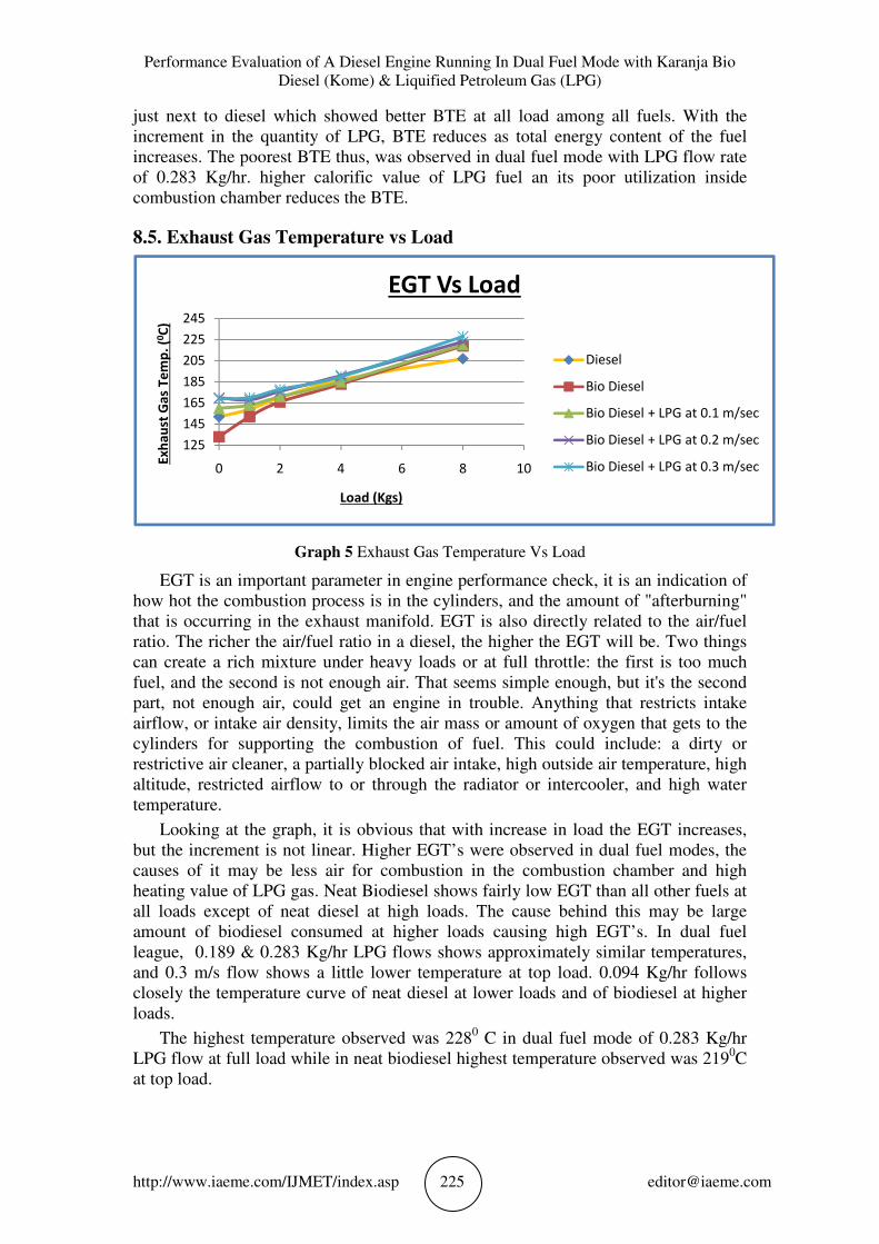
8.5. Exhaust Gas Temperature vs Load
Graph 5 Exhaust Gas Temperature Vs Load
EGT is an important parameter in engine performance check, it is an indication of
how hot the combustion process is in the cylinders, and the amount of "afterburning"
that is occurring in the exhaust manifold. EGT is also directly related to the air/fuel
ratio. The richer the air/fuel ratio in a diesel, the higher the EGT will be. Two things
can create a rich mixture under heavy loads or at full throttle: the first is too much
fuel, and the second is not enough air. That seems simple enough, but it's the second
part, not enough air, could get an engine in trouble. Anything that restricts intake
airflow, or intake air density, limits the air mass or amount of oxygen that gets to the
cylinders for supporting the combustion of fuel. This could include: a dirty or
restrictive air cleaner, a partially blocked air intake, high outside air temperature, high
altitude, restricted airflow to or through the radiator or intercooler, and high water
temperature.
Looking at the graph, it is obvious that with increase in load the EGT increases,
but the increment is not linear. Higher EGT’s were observed in dual fuel modes, the
causes of it may be less air for combustion in the combustion chamber and high
heating value of LPG gas. Neat Biodiesel shows fairly low EGT than all other fuels at
all loads except of neat diesel at high loads. The cause behind this may be large
amount of biodiesel consumed at higher loads causing high EGT’s. In dual fuel
league, 0.189 & 0.283 Kg/hr LPG flows shows approximately similar temperatures,
and 0.3 m/s flow shows a little lower temperature at top load. 0.094 Kg/hr follows
closely the temperature curve of neat diesel at lower loads and of biodiesel at higher
loads.
The highest temperature observed was 2280 C in dual fuel mode of 0.283 Kg/hr
LPG flow at full load while in neat biodiesel highest temperature observed was 2190C
at top load.
125
145
165
185
205
225
245
0 2 4 6 8 10
Ex
ha
ust
Ga
s T
em
p.
(0C
)
Load (Kgs)
EGT Vs Load
Diesel
Bio Diesel
Bio Diesel + LPG at 0.1 m/sec
Bio Diesel + LPG at 0.2 m/sec
Bio Diesel + LPG at 0.3 m/sec
Chanderbhan Singh Tomar, Ravindra Randa and Suraj Dev Singh
http://www.iaeme.com/IJMET/index.asp 226 [email protected]
9. CONCLUSION
A comprehensive experimental work on the performance measurement of diesel
engine running on 100% KOME biodiesel and to convert it into dual fuel engine with
the help of LPG kit has been carried out successfully. Following important outcomes
derived from the experiment.
1. Fuel consumption was reduced in dual fuel mode. At no load, biodiesel consumption
was 0.357 while with LPG at0.094, 0.189 & 0.283 Kg/hr it was 0.334, 0.292 & 0.282
kg/kwhr respectively. Thus there was a saving of 6.44%, 18.20% & 21.00%
respectively. At top load of 8 kg, the savings were 4.38%, 8.356% & 12.05%
respectively. Thus at higher loads savings were not as good as lower loads.
2. BSFC also got reduced in dual fuel mode. At 1 kg load, the improvement in dual fuel
mode at LPG flow rates of 0.094, 0.189 & 0.283 Kg/hr were 16.56%, 27.60% &
30.06% respectively. While at top load of 8 kg these improvements were 32.43%,
32.43% & 37.837% respectively. It is quite clear that BSFC was largely improved in
dual fuel mode.
3. BSEC and BTE didn’t got improved in dual fuel modes, although low LPG flow rates
give comparable results in BSEC but not in BTE, increased concentration of LPG in
successive stages worsen the BTE. The higher calorific value of LPG and lower
utilization of it causes to reduce BTE by increasing the overall non utilized energy
input to the engine. This can be overcame by using advance techniques such as
electronically timed and controlled injection of fuel to determine the needed quantity
of fuel in engine, exhaust gas recirculation to utilize unburned HC, glow plugs for
reducing the ignition delay at higher speeds and loads and additives for the biodiesel
to reduce its density etc. although, it is still unsure that they will improve BTE to
great extent but keeping in mind that biodiesel is a future fuel, it needs to be worked
out.
4. Exhaust gas temperature increased in dual fuel modes. The high heating value of LPG
is the main cause behind it. Better cooling systems in which the cooling fluid
quantities are also changeable are needed to employ dual fuel systems in diesel
engines to keep the EGT in limit at higher loads. High temperature inside the
combustion chamber may also harm the engine parts and reduce the mechanical
strength it is very essential to take care of cooling inside the combustion chamber.
5. The cost of cooking LPG used is around 32 INR per kg in India while the biodiesel
that we made at laboratory in the university costs us 265 INR per Liter which is quite
high because of high cost of raw materials used in making it. It’s very important to
make biodiesel at large levels to bring its cost down otherwise it will not become
popular and researches will be disappointed morally.
6. None of the LPG /Bio Diesel mix systems examined has resulted in Biodiesel
consumption being reduced by more than 21%. Those savings made also have LPG
costs (for the LPG that replaces some of the biodiesel fuel consumed) subtracted from
that 21% saving. Due to cause of insufficient utilization of LPG, the savings do not
come huge but research and technology in future will definitely fill this gap and make
biodiesel –LPG a popular fuel.
7. There are other problems to consider as well - The unmodified Diesel engine was
relatively slow-revving, producing its maximum torque at lower RPM than a similar
Petrol version and was used to run with fuels having density like diesel. This is not
the case when it is converted to run on biodiesel and LPG mix. The revised engine
has to'rev' more when running on biodiesel / LPG mix because its maximum torque
will have been moved higher up the rev. band. This can bring new problems of
reliability and longevity. The crankshaft, bearings and connecting rods (to mention
but a few components) were all designed to rev. at a lower rate. These components
will suffer much higher stresses (stress increases at the square of RPM) at the
Performance Evaluation of A Diesel Engine Running In Dual Fuel Mode with Karanja Bio
Diesel (Kome) & Liquified Petroleum Gas (LPG)
http://www.iaeme.com/IJMET/index.asp 227 [email protected]
increased RPM necessary to get sufficient torque when running on LPG. Mechanical
breakdown may result in far less time, whilst increased wear and reduced component
life are certain. Also, the high density of biodiesel clogs the engines valves sometime
and if not perfectly treated before operation may wear the engine more rapidly. If not
taken care of the issues, this does not seem to be an economically viable alternative.
But as we know, diesel reserves are depleting, we must concentrate on improving
biodiesel performance and technologies for improving it.
Thus as a conclusion, the fumigation method used in this experiment does not
appear to be an attractive or useful alternative for the average diesel engine. Also the
biodiesel –LPG mix isn’t viable until cost issues and chemical issues are solved. But
as far as future is concerned, biodiesel seems to be a perfect alternative for diesel,
only more researches on engine design and fuel utilization are needed to be done.
10. SCOPE OF FUTURE WORK
Biodiesel has a great importance in alternative fuel league and is most viable future
fuel for running the workhorses. Its low calorific value problem can be eliminated
with the help of dual fuel techniques where it can be either mixed with the LPG or
CNG or Natural gas which has greater calorific values. The high density problem
must be taken into account and research must be done to make its density comparable
with petroleum diesel so that clogging and choking, cold start, sludge in engine kind
of problems could be eliminated. To improve the performance of a dual fuel engine, a
turbocharger to provide more air (or oxygen) for the combustion, must be installed. It
will help in complete combustion of fuel and will reduce exhaust gas temperature thus
improving the engine life. Apart from that, precise electronic control system must be
installed to watch the combustion patterns and needs in combustion chambers and for
providing best ratio of biodiesel and LPG. A good exhaust gas recirculation system
monitored electronically must be employed to engine to utilize any unburned HC.
Some advance additives and catalyst might be added to fuel for smoother and efficient
combustion. The concept of present work might be employed with some
modifications and with other fuels such as CNG and Natural gas.
ACKNOWLEDGMENT
The authors wish to acknowledge the support rendered by University Institute of
Technology, Bhopal in preparation of this Manuscript.
REFERENCES
[1] Gunatilake, H., D. Roland-Holst, and G. Sugiarto. 2011. Energy Security and
Economics of Indian Biofuel Strategy in Global Context. ADB Economics and
Research Department Working Paper Series. Manila: Asian Development Bank.
[2] Ministry of Petroleum and Natural Gas (MOPNG). 2009. Basic Statistics on
Petroleum and Natural Gas, 2008–2009. Delhi.
[3] Government of India (GOI). 2003. Report of the Committee on the Development
of Bio-fuel. Delhi 2006. Integrated Energy Policy, Planning Commission.
[4] http://americandieselsystems.com/diesel-reduction-technology.php
[5] http://depts.washington.edu/vehfire/fuels/detailedresults.html
[6] http://www.elgas.com.au/blog/453-the-science-a-properties-of-lpg
[7] https://iocl.com/Products/LPGSpecifications.pdf

Chanderbhan Singh Tomar, Ravindra Randa and Suraj Dev Singh
http://www.iaeme.com/IJMET/index.asp 228 [email protected]
[8] N. Shrivastava, S.N. Varma and M. Pandey-2012, Experimental Study on the
Production of Karanja Oil Methyl Ester and Its Effect on Diesel Engine
(www.ijred.com)
[9] Mr. Lijo P Varghese, Mr. Rajiv Saxena And Dr. R.R. Lal, Analysis of The Effect
of Nozzle Hole Diameter on CI Engine Performance Using Karanja Oil-Diesel
Blends. International Journal of Mechanical Engineering and Technology, 4(4),
2013, pp. 79-88.
[10] Rajan Kumar, Dr. Manoj K Mishra and Dr. Shyam K Singh, Performance and
Emission Study of Jatropha Biodiesel and Its Blends on C.I. Engine. International
Journal of Mechanical Engineering and Technology, 4(3), 2013, pp. 85 - 93.