Embed Size (px)
Citation preview

Sub: DC Machines and Transformer (2130904)Active Learning Assignment
Topic: O.C & S.C Test, Sumpner or back to back Test, Condition for maximum efficiency, All day EfficiencyGuided By: Prof. Hitesh MananiBranch: Electrical Engineering Div: BPrepared By: (1) Abhishek Choksi 140120109005 (2) Himal Desai 140120109008 (3) Harsh Dedakiya 140120109012
Contents• Open Circuit or no load test• Short Circuit or Impedance Test• Sumpner or Back to Back Test• Condition for Maximum Efficiency• All day Efficiency
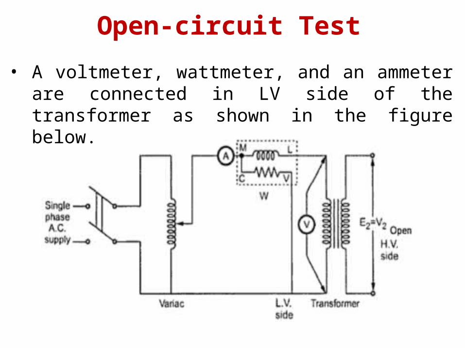
Open-circuit Test• A voltmeter, wattmeter, and an ammeter are connected in
LV side of the transformer as shown in the figure below.
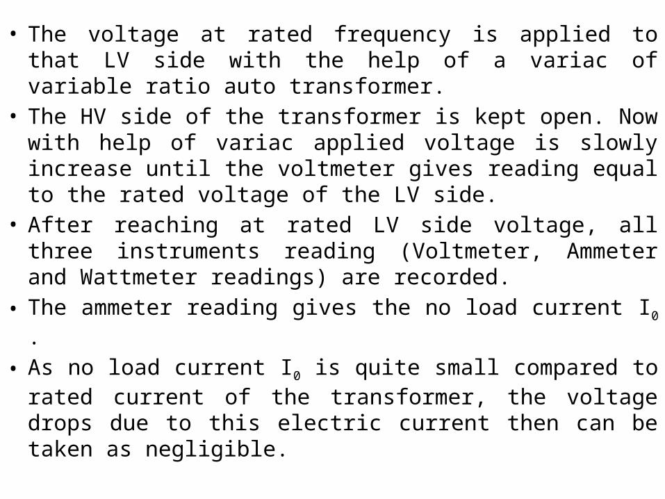
• The voltage at rated frequency is applied to that LV side with the help of a variac of variable ratio auto transformer.
• The HV side of the transformer is kept open. Now with help of variac applied voltage is slowly increase until the voltmeter gives reading equal to the rated voltage of the LV side.
• After reaching at rated LV side voltage, all three instruments reading (Voltmeter, Ammeter and Wattmeter readings) are recorded.
• The ammeter reading gives the no load current I0 .• As no load current I0 is quite small compared to rated
current of the transformer, the voltage drops due to this electric current then can be taken as negligible.

• Since, voltmeter reading V can be considered equal to secondary induced voltage of the transformer. The input power during test is indicated by watt-meter reading.
• As the transformer is open circuited, there is no output hence the input power here consists of core losses in transformer and copper loss in transformer during no load condition.
• The no load current in the transformer is quite small compared to full load current so copper loss due to the small no load current can be neglected.
• Hence the wattmeter reading can be taken as equal to core losses in transformer.
• Therefore it is seen that the open circuit test on transformer is used to determine core losses in transformer and parameters of shunt branch of the equivalent circuit of transformer.
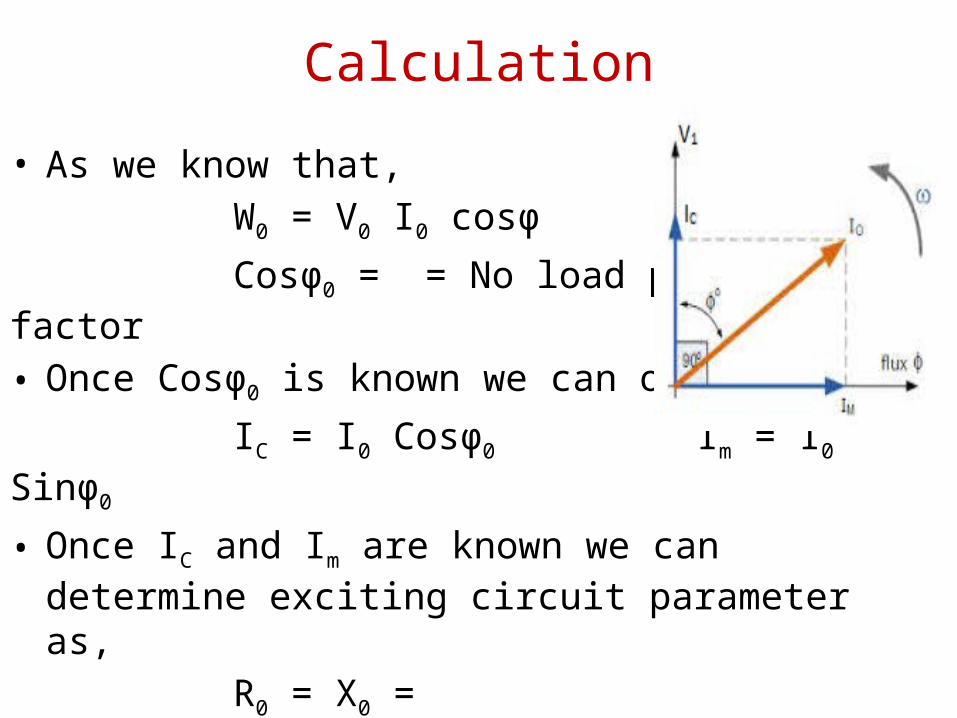
Calculation• As we know that, W0 = V0 I0 cosφ Cosφ0 = = No load power factor• Once Cosφ0 is known we can obtain, IC = I0 Cosφ0 Im = I0 Sinφ0 • Once IC and Im are known we can determine exciting
circuit parameter as, R0 = X0 =

Short-circuit Test• A voltmeter, wattmeter, and an ammeter are connected in
HV side of the transformer as shown in figure.
• The voltage at rated frequency is applied to that HV side with the help of a variac of variable ratio auto transformer
• The LV side of the transformer is short circuited . Now with help of variac applied voltage is slowly increase until the ammeter gives reading equal to the rated current of the HV side
• After reaching at rated current of HV side, all three instruments reading (Voltmeter, Ammeter and Watt-meter readings) are recorded
• The ammeter reading gives the primary equivalent of full load current IL .
• As the voltage, applied for full load current in short circuit test on transformer, is quite small compared to rated primary voltage of the transformer, the core losses in transformer can be taken as negligible here.

• Let’s, voltmeter reading is VSC . The input power during test is indicated by watt-meter reading.
• As the transformer is short circuited, there is no output hence the input power here consists of copper losses in transformer
• Since, the applied voltage VSC is short circuit voltage in the transformer and hence it is quite small compared to rated voltage so core loss due to the small applied voltage can be neglected.
• Hence the wattmeter reading can be taken as equal to copper losses in transformer.
• Therefore it is seen that the Short Circuit test on transformer is used to determine copper loss in transformer at full load and parameters of approximate equivalent circuit of transformer.
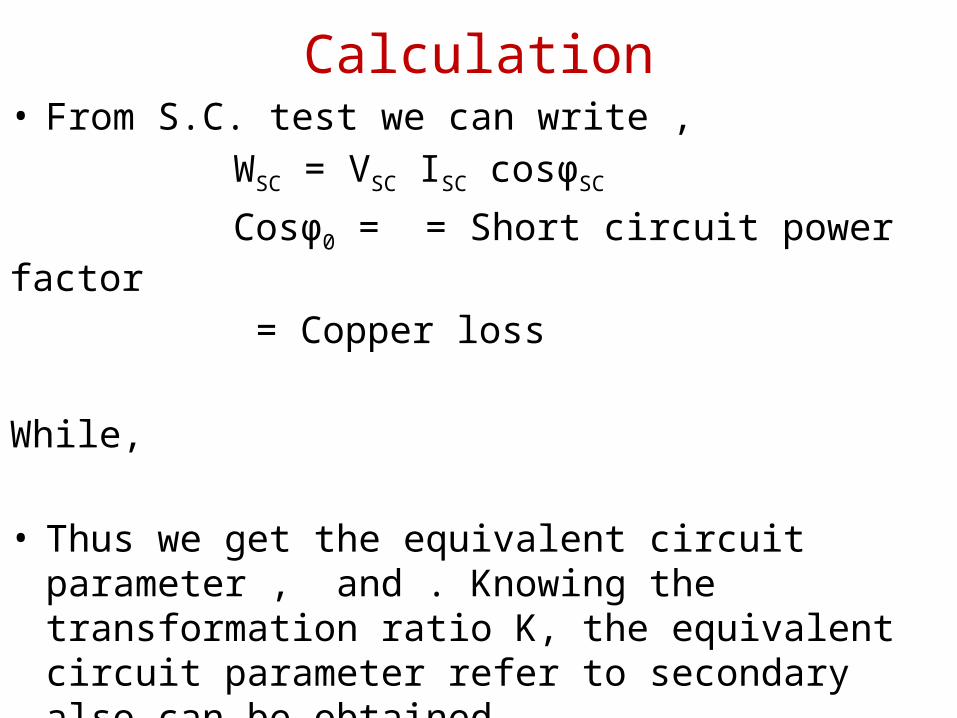
Calculation• From S.C. test we can write , WSC = VSC ISC cosφSC Cosφ0 = = Short circuit power factor = Copper loss While, • Thus we get the equivalent circuit parameter , and .
Knowing the transformation ratio K, the equivalent circuit parameter refer to secondary also can be obtained.
Draw back of Open Circuit and Short Circuit
• In O.C. test, there is no load on the transformer while in S.C. circuit test only fractional load gets applied. In all O.C. and S.C. tests, the loading conditions are absent. Hence the results are inaccurate.
• In open and short circuit test iron losses and copper losses are determined separately but in actual use both losses occurs simultaneously.
• The temperature rise in the transformer is due to total loss that occurs simultaneously during actual use, it can’t be determined by O.C and S.C tests.

Sumpner or Back-to-Back Test• Sumpner's test or back to back test on transformer is
another method for determining transformer efficiency, voltage regulation and heating under loaded conditions.
• The figure above shows that the connection diagram of back to back test on two similar transformers named T1 and T2.
• Both transformers are connected to supply such that one transformer is loaded on another.
• Primaries of the two identical transformers are connected in parallel across a supply.
• Secondary are connected in series such that emf's of them are opposite to each other.
• Another low voltage supply is connected in series with secondary to get the readings, as shown in the circuit diagram.

Working• The transformer secondary sides are in phase opposition. • Then switch S2 is open and switch S1 is closed, thus the
circulating current in the transformer secondary circuit loop is zero (i.e. I2=0).
• This is due to EMF induced in the secondary’s are in equal and opposition.
• This circumstance is just like an open circuit test. Hence the current drawn from the source is 2I0.
• The wattmeter reading W1 and the core loss of both the transformers are equal.
• I0= No load current of every transformer• W1 = Core losses of both the transformers.

• Now switch S2 also closed and the voltage at the output of the regulating transformer is varied until the full load current I2 drift in the secondary circuit loop.
• The secondary full load current will cause full load current I1in the primary circuit.
• The full load current I1 will circulates in the primary winding alone.
• The two transformers full load copper losses is equal wattmeter W2 reading since the full load current circulating through the primary winding and secondary windings.
• W2 = Transformer full load copper losses• W2+W1 = Total losses of the two transformers at full load.
• From above test results, the full load efficiency of each transformer can be given as –
% full load efficiency of each transformer =

Advantages of Sumpner’s Test• Little much of power is required to conduct this test• Under full load conditions transformers can be test using
this test.• Simultaneously full load copper losses and iron losses are
measured• The secondary current I2 can be varied at any value of the
current. Hence we can determine the copper losses at full load condition or at any load.
• The transformer temperature increase can be noted.

• Only limitation is that two identical transformers are required. In practice exact identical transformers cannot be obtained and as two transformers are required, the test is not economical.
Drawback of Sumpner’s Test
Efficiency of a transformer• As in the case of electrical machines, the efficiency of a
transformer at particular load and power factor is defined as the output divided by the input the two being measured in the same units i.e in watts or kilowatts.
Efficiency = • But the transformer being highly piece of equipment, has
very small loss, hence it is impractical to try to measure transformer, efficiency by measuring input and output. These quantities are nearly of the same size.
• A better method is to determine the losses and then to calculate the efficiency from,
Efficiency = Or, Ƞ = • It may be noted here that efficiency is based on power
output in watts and not in volt-amperes, although losses are proportional to VA.
• Hence at any volt-ampere load, the efficiency depend on power factor, being maximum at a power factor of unity.

Condition for Maximum EfficiencyCu loss = or
Iron loss = Hysteresis loss + Eddy current loss = • Considering primary side, Primary output =
Ƞ =
Differentiating both the side with respect to , we get
• For to be maximum, = 0. Hence, the above equation
becomes or or Cu loss = Iron loss• The output current corresponding to maximum efficiency
is . • It is this value of the output current which will make the Cu
loss equal to iron loss.

All day efficiency• The commercial Efficiency of a transformer is given by the ratio
of output power to input power
• The losses in the transformer can be classified into copper losses and iron losses. The copper losses (hysteresis and Eddy Current Losses) are independent of the load. The iron losses though are dependent on the load.
•In the case of the distribution transformers, the load is continually varying. It is low in the day time and high in the evenings and night. Therefore, efficiency measured at any one point of the day would not be an accurate reflection of the transformer's capability.
Efficiency=output power in wattsinput power in watts
• Hence, We have the all day efficiency measurement of the distribution transformers. The formula for the all day efficiency of the distribution transformers is
• The All day Efficiency is always lesser than the commercial efficiency of the transformer.
Efficiency * 100

Reference• U.A. Bakshi• B.L. Theraja• http://www.mytech-info.com• https://en.wikipedia.org

THANK YOU