Embed Size (px)
Citation preview
B-1
Ca
m F
oll
ow
er
Be
ari
ng
s
B-2
Cam FollowersUnmounted bearing assembly consisting
of hardened precision ground inner
and outer raceways with either full
complement or separated (cage) needle,
ball, tapered or cylindrical rolling
elements constructed with an integral
stud or precision ground bore. Cam
follower bearings provide an antifriction
solution for translating rotation to linear
motion or supporting either pure radial or
combination thrust loads depending on
the rolling elements types.
Bearing Configurations
Cylindrical, Crowned, V-Groove Or Flanged
Mounting Styles
Eccentric Or Concentric Stud Or Yoke
Outer Roller Diameter Range
1/2” To 10” And 13 mm To 90 mm
Materials
Bearing Quality Steel, Stainless
Ca
m F
oll
ow
er
Be
ari
ng
s
B-3
Ca
m F
oll
ow
er
Be
ari
ng
s
Inch Cam Follower Bearings
B-3
Size Range DeSign ChaRaCteRiStiCS FeatuReS
Product Series Material / Finish Inch Metric Radial Load
Thrust Load Precision High
Speed
Relative Base Cost *
Crowned OD
Eccentric Stud
Lubrication Holes Seal Hex Hole Slotted
Face Jam Nuts Page No.
CAMROL
CF
Black Oxide Finish Bearing Steel
1/2 - 10 $ O O S O O S - B-15
CYR 3/4 - 10 $ O - S O - - - B-39
CFH 1/2 - 7 $$ O - S O O S - B-15
BCF 1/2 - 4 $ O O S O O S - B-45
BCYR 3/4 - 4 $ O - S O - - - B-57
MCF 16 - 90 $ S O S O O S S B-69
MCFR 13 - 90 $ S O S O O S S B-69
MCYR 5 - 50 $ S - S O O - S B-91
MCYRR 5 - 50 $ S - S O - - S B-91
Heavy-Duty
CFD
Black Oxide Finish Bearing Steel
1 1/4 - 6 $$ O O O S S - - B-103
CYRD 1 1/4 - 6 $$ O - O S - - - B-107
MCFD 35 - 80 $$ S O S - O S S B-111
MCYRD 15 - 50 $$ S - S - - - - B-115
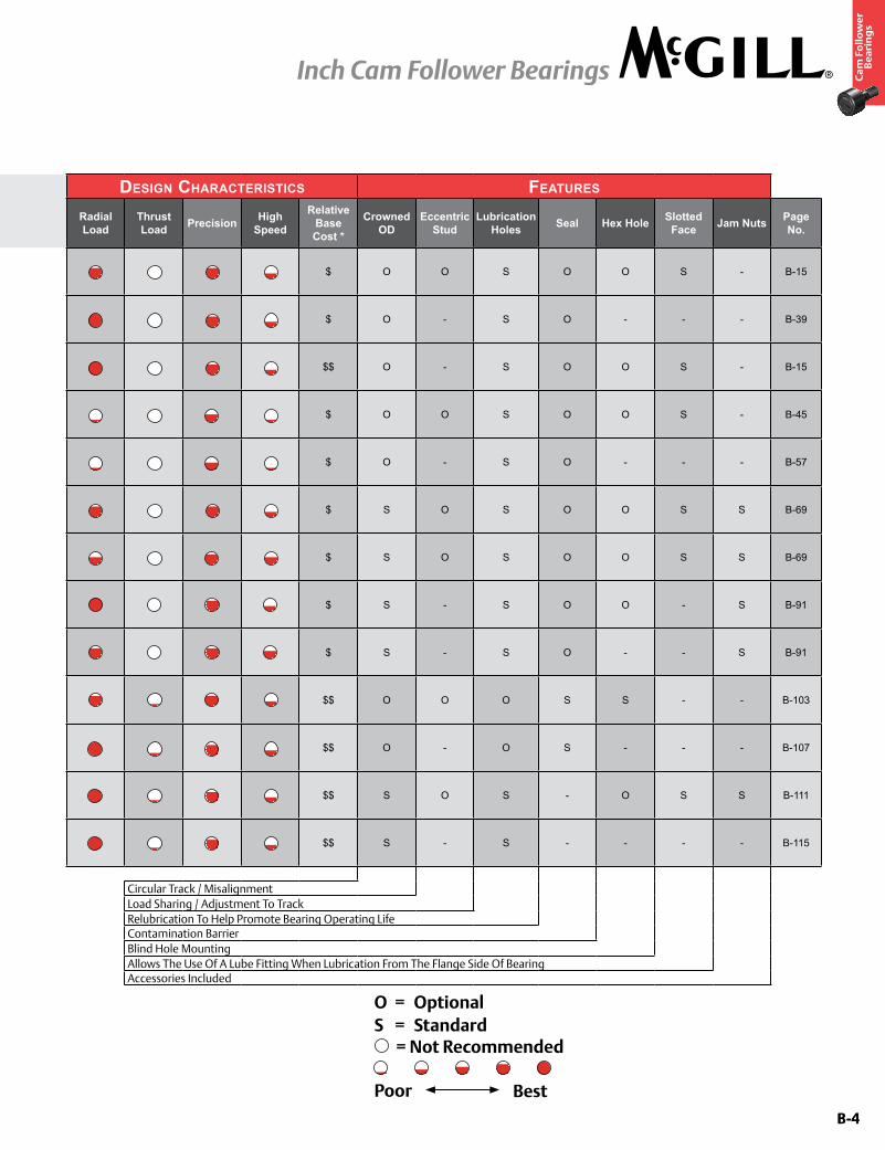
Circular Track / MisalignmentLoad Sharing / Adjustment To Track
Relubrication To Help Promote Bearing Operating LifeContamination BarrierBlind Hole MountingAllows The Use Of A Lube Fitting When Lubrication From The Flange Side Of BearingAccessories Included
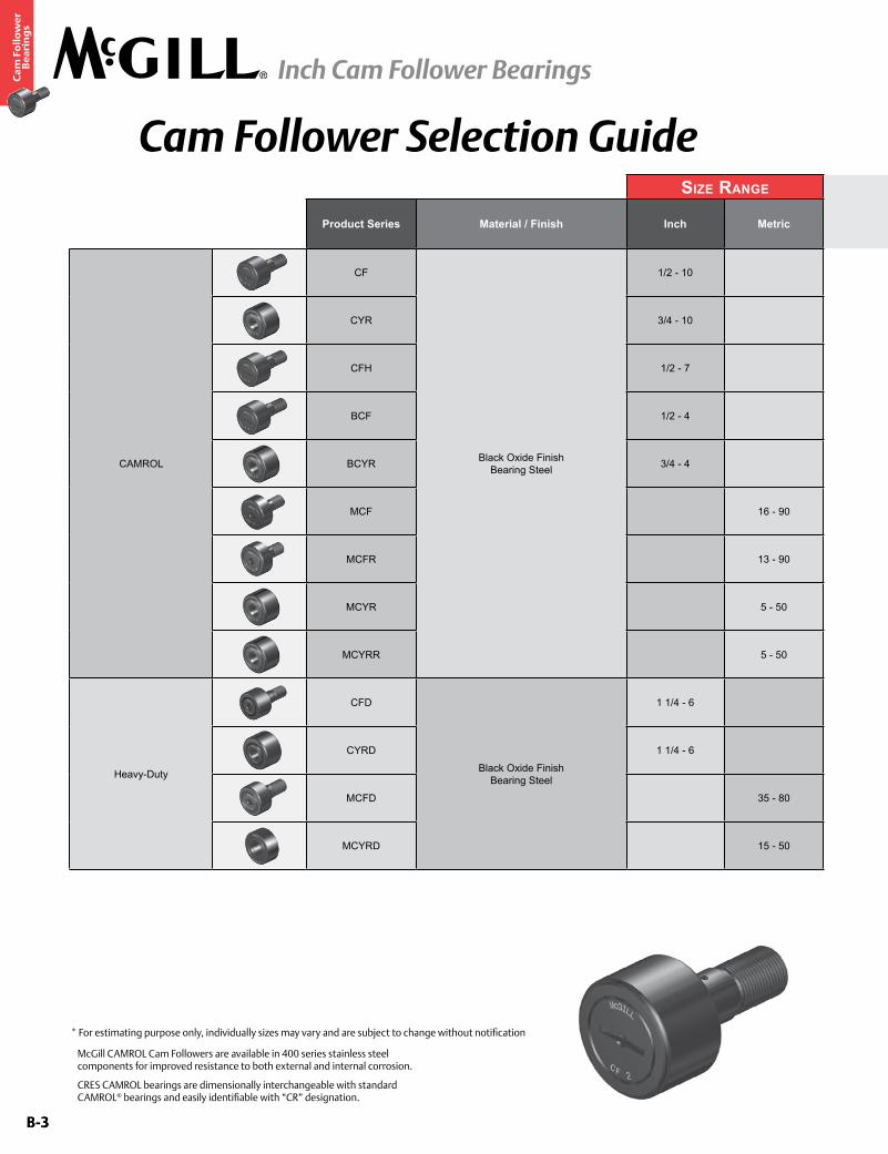
Cam Follower Selection Guide
* For estimating purpose only, individually sizes may vary and are subject to change without notification
McGill CAMROL Cam Followers are available in 400 series stainless steel components for improved resistance to both external and internal corrosion.
CRES CAMROL bearings are dimensionally interchangeable with standard CAMROL® bearings and easily identifiable with “CR” designation.
B-4
Ca
m F
oll
ow
er
Be
ari
ng
s
Inch Cam Follower Bearings
B-4
Size Range DeSign ChaRaCteRiStiCS FeatuReS
Product Series Material / Finish Inch Metric Radial Load
Thrust Load Precision High
Speed
Relative Base Cost *
Crowned OD
Eccentric Stud
Lubrication Holes Seal Hex Hole Slotted
Face Jam Nuts Page No.
CAMROL
CF
Black Oxide Finish Bearing Steel
1/2 - 10 $ O O S O O S - B-15
CYR 3/4 - 10 $ O - S O - - - B-39
CFH 1/2 - 7 $$ O - S O O S - B-15
BCF 1/2 - 4 $ O O S O O S - B-45
BCYR 3/4 - 4 $ O - S O - - - B-57
MCF 16 - 90 $ S O S O O S S B-69
MCFR 13 - 90 $ S O S O O S S B-69
MCYR 5 - 50 $ S - S O O - S B-91
MCYRR 5 - 50 $ S - S O - - S B-91
Heavy-Duty
CFD
Black Oxide Finish Bearing Steel
1 1/4 - 6 $$ O O O S S - - B-103
CYRD 1 1/4 - 6 $$ O - O S - - - B-107
MCFD 35 - 80 $$ S O S - O S S B-111
MCYRD 15 - 50 $$ S - S - - - - B-115
Circular Track / MisalignmentLoad Sharing / Adjustment To Track
Relubrication To Help Promote Bearing Operating LifeContamination BarrierBlind Hole MountingAllows The Use Of A Lube Fitting When Lubrication From The Flange Side Of BearingAccessories Included
O = OptionalS = Standard
= Not Recommended
Poor Best
B-5
Ca
m F
oll
ow
er
Be
ari
ng
s
Inch Cam Follower Bearings
B-5
Size Range DeSign ChaRaCteRiStiCS FeatuReS
Product Series Material / Finish Inch Metric Radial Load
Thrust Load Precision High
Speed
Relative Base Cost *
Crowned OD
Eccentric Stud
Lubrication Hole Seal Hex Hole Slotted
Face Jam Nuts Page No.
Special Duty
SDCF
Black Oxide Finish Bearing Steel
1 - 4 $$$ O O - S S - S B-123
SDMCF 25 - 100 $$$ O O - S S - S B-125
TRAKROL
PCF
Black Oxide Finish Bearing Steel
1 1/2 - 9 $$ O O - S - - O B-131
PCYR 3 - 6 $$ O - - S S - - B-133
FCF 1 1/2 - 9 $$$ - O - S S - O B-135
FCYR 3 - 6 $$ - - - S - - - B-137
VCF 2 1/2 - 8 1/2 $$ - O - S S - O B-139
VCYR 3 1/2 - 7 1/2 $$ - - - S - - - B-141
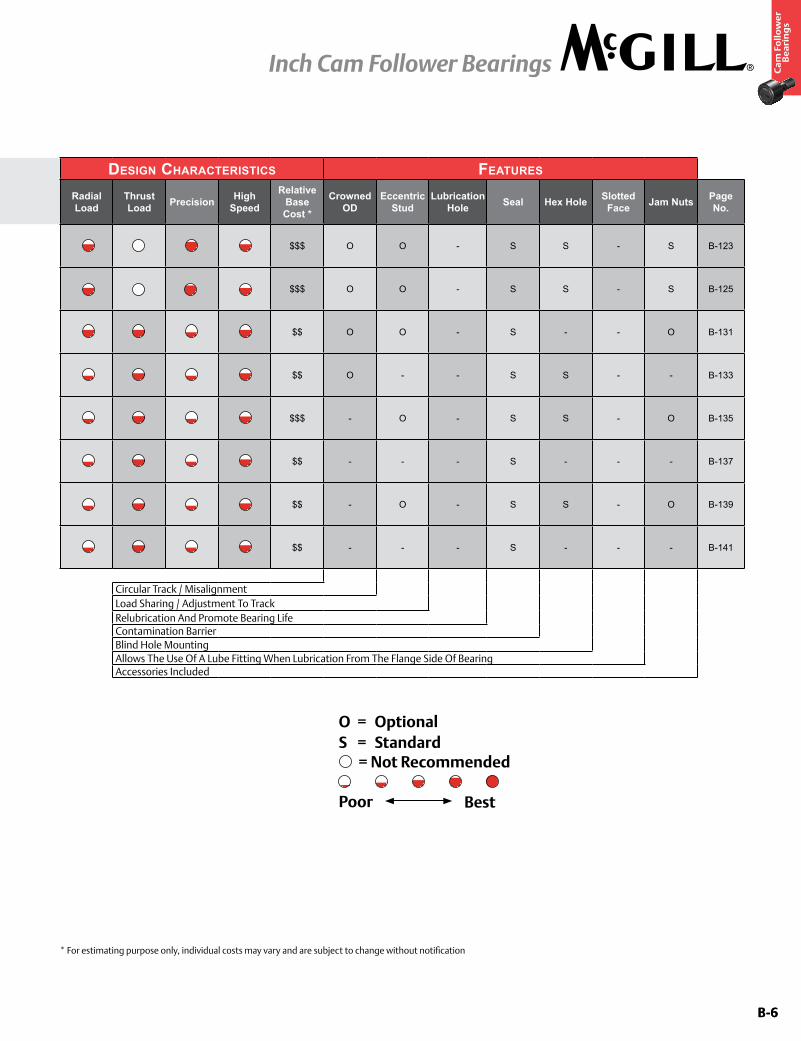
Circular Track / MisalignmentLoad Sharing / Adjustment To Track
Relubrication And Promote Bearing LifeContamination BarrierBlind Hole MountingAllows The Use Of A Lube Fitting When Lubrication From The Flange Side Of BearingAccessories Included
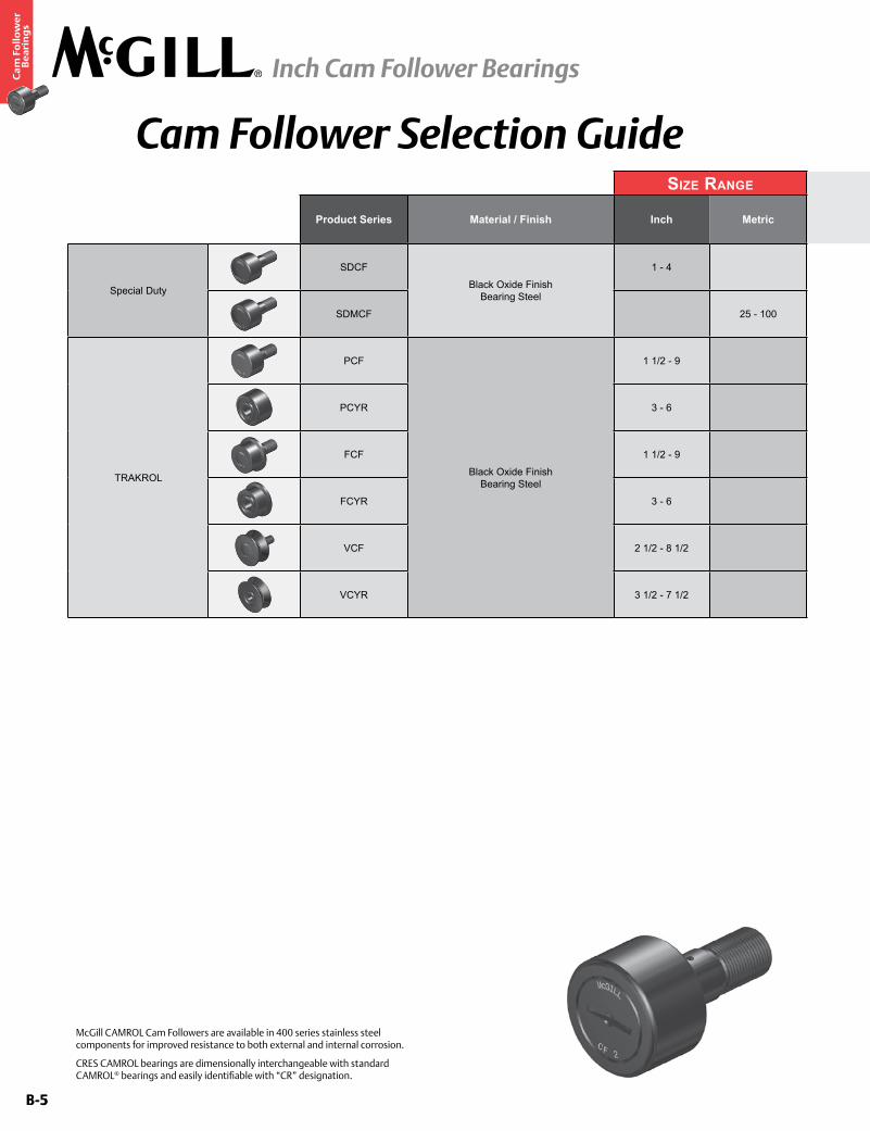
Cam Follower Selection Guide
McGill CAMROL Cam Followers are available in 400 series stainless steel components for improved resistance to both external and internal corrosion.
CRES CAMROL bearings are dimensionally interchangeable with standard CAMROL® bearings and easily identifiable with “CR” designation.
B-6
Ca
m F
oll
ow
er
Be
ari
ng
s
Inch Cam Follower Bearings
B-6
Size Range DeSign ChaRaCteRiStiCS FeatuReS
Product Series Material / Finish Inch Metric Radial Load
Thrust Load Precision High
Speed
Relative Base Cost *
Crowned OD
Eccentric Stud
Lubrication Hole Seal Hex Hole Slotted
Face Jam Nuts Page No.
Special Duty
SDCF
Black Oxide Finish Bearing Steel
1 - 4 $$$ O O - S S - S B-123
SDMCF 25 - 100 $$$ O O - S S - S B-125
TRAKROL
PCF
Black Oxide Finish Bearing Steel
1 1/2 - 9 $$ O O - S - - O B-131
PCYR 3 - 6 $$ O - - S S - - B-133
FCF 1 1/2 - 9 $$$ - O - S S - O B-135
FCYR 3 - 6 $$ - - - S - - - B-137
VCF 2 1/2 - 8 1/2 $$ - O - S S - O B-139
VCYR 3 1/2 - 7 1/2 $$ - - - S - - - B-141
Circular Track / MisalignmentLoad Sharing / Adjustment To Track
Relubrication And Promote Bearing LifeContamination BarrierBlind Hole MountingAllows The Use Of A Lube Fitting When Lubrication From The Flange Side Of BearingAccessories Included
* For estimating purpose only, individual costs may vary and are subject to change without notification
O = OptionalS = Standard
= Not Recommended
Poor Best
B-7
Ca
m F
oll
ow
er
Be
ari
ng
s
Inch Cam Follower Bearings
B-7
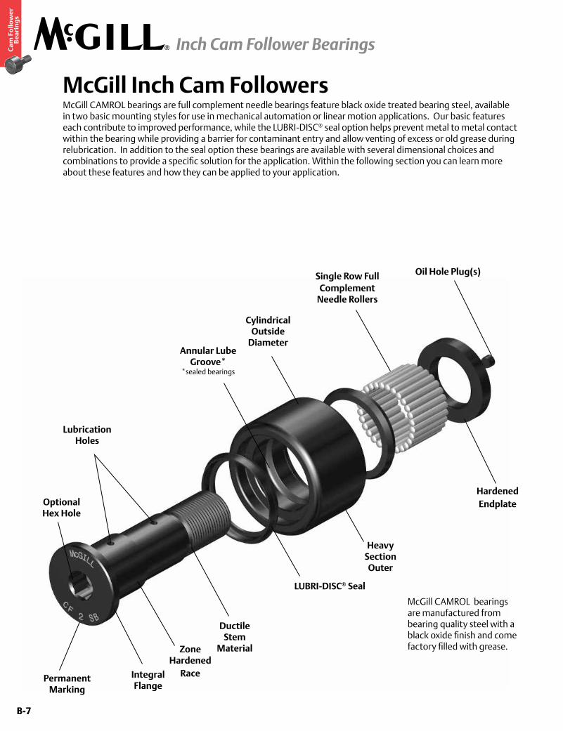
McGill Inch Cam FollowersMcGill CAMROL bearings are full complement needle bearings feature black oxide treated bearing steel, available in two basic mounting styles for use in mechanical automation or linear motion applications. Our basic features each contribute to improved performance, while the LUBRI-DISC® seal option helps prevent metal to metal contact within the bearing while providing a barrier for contaminant entry and allow venting of excess or old grease during relubrication. In addition to the seal option these bearings are available with several dimensional choices and combinations to provide a specific solution for the application. Within the following section you can learn more about these features and how they can be applied to your application.
Cylindrical Outside
DiameterAnnular Lube
Groove**sealed bearings
Single Row Full Complement
Needle Rollers
Lubrication Holes
Zone Hardened
RacePermanent Marking
Integral Flange
Ductile Stem
Material
Heavy Section Outer
LUBRI-DISC® Seal
Hardened Endplate
Oil Hole Plug(s)
McGill CAMROL bearings are manufactured from bearing quality steel with a black oxide finish and come factory filled with grease.
Optional Hex Hole
B-8
Ca
m F
oll
ow
er
Be
ari
ng
s
Inch Cam Follower Bearings
B-8
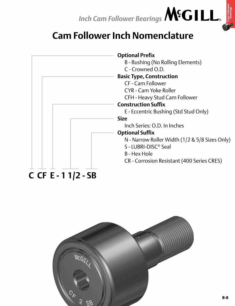
Cam Follower Inch Nomenclature
Optional Prefix B - Bushing (No Rolling Elements) C - Crowned O.D.Basic Type, Construction CF - Cam Follower CYR - Cam Yoke Roller CFH - Heavy Stud Cam FollowerConstruction Suffix E - Eccentric Bushing (Std Stud Only)Size Inch Series: O.D. In Inches Optional Suffix N - Narrow Roller Width (1/2 & 5/8 Sizes Only) S - LUBRI-DISC® Seal B - Hex Hole CR - Corrosion Resistant (400 Series CRES)
C CF E - 1 1/2 - SB
B-9
Ca
m F
oll
ow
er
Be
ari
ng
s
Inch Cam Follower Bearings
B-9
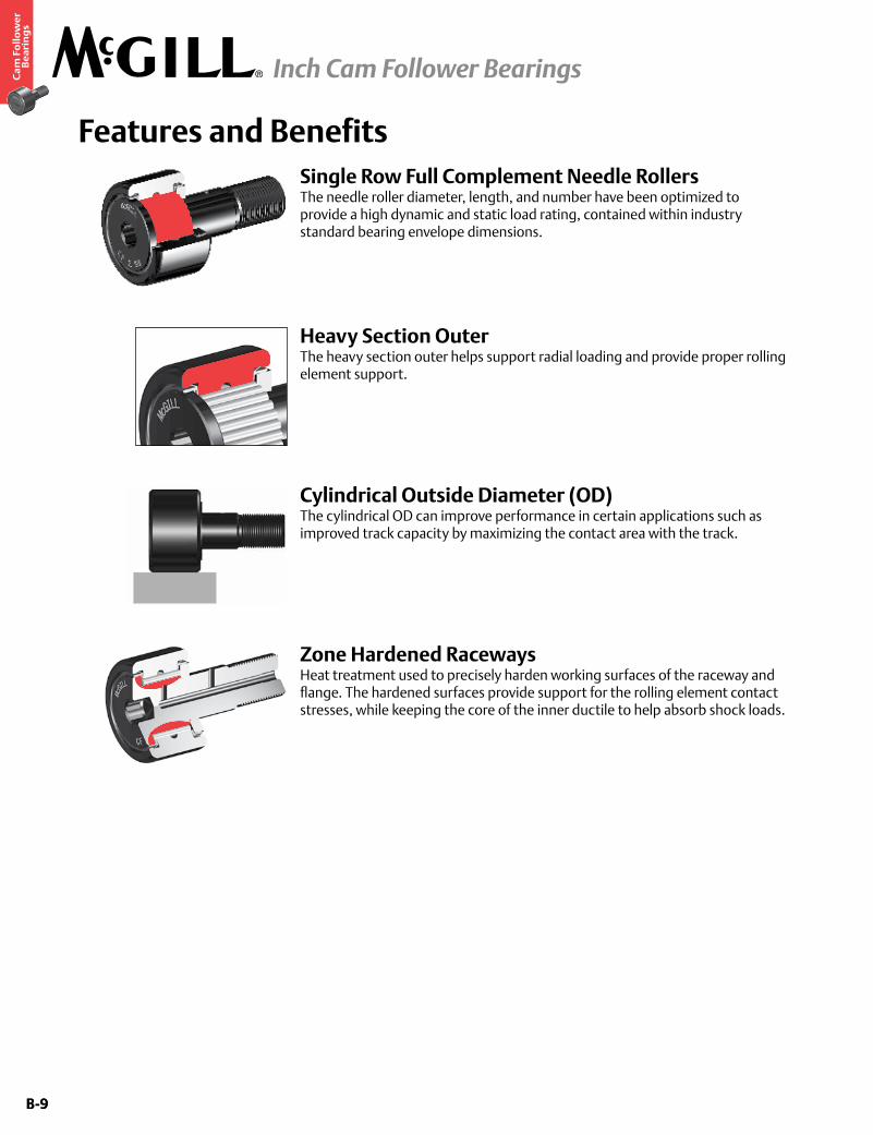
Features and BenefitsSingle Row Full Complement Needle RollersThe needle roller diameter, length, and number have been optimized to provide a high dynamic and static load rating, contained within industry standard bearing envelope dimensions.
Cylindrical Outside Diameter (OD)The cylindrical OD can improve performance in certain applications such as improved track capacity by maximizing the contact area with the track.
Heavy Section OuterThe heavy section outer helps support radial loading and provide proper rolling element support.
Zone Hardened RacewaysHeat treatment used to precisely harden working surfaces of the raceway and flange. The hardened surfaces provide support for the rolling element contact stresses, while keeping the core of the inner ductile to help absorb shock loads.
B-10
Ca
m F
oll
ow
er
Be
ari
ng
s
Inch Cam Follower Bearings
B-10
Features and Benefits continued
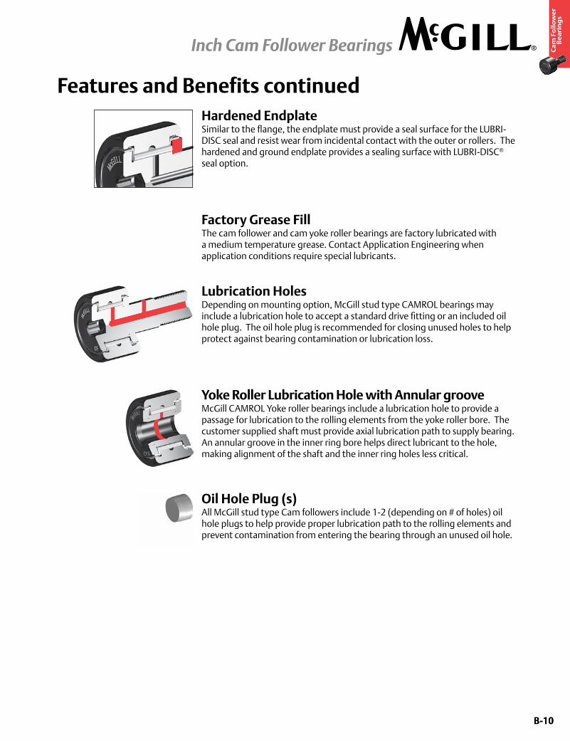
Factory Grease FillThe cam follower and cam yoke roller bearings are factory lubricated with a medium temperature grease. Contact Application Engineering when application conditions require special lubricants.
Lubrication HolesDepending on mounting option, McGill stud type CAMROL bearings may include a lubrication hole to accept a standard drive fitting or an included oil hole plug. The oil hole plug is recommended for closing unused holes to help protect against bearing contamination or lubrication loss.
Yoke Roller Lubrication Hole with Annular grooveMcGill CAMROL Yoke roller bearings include a lubrication hole to provide a passage for lubrication to the rolling elements from the yoke roller bore. The customer supplied shaft must provide axial lubrication path to supply bearing. An annular groove in the inner ring bore helps direct lubricant to the hole, making alignment of the shaft and the inner ring holes less critical.
Hardened EndplateSimilar to the flange, the endplate must provide a seal surface for the LUBRI-DISC seal and resist wear from incidental contact with the outer or rollers. The hardened and ground endplate provides a sealing surface with LUBRI-DISC® seal option.
Oil Hole Plug (s)All McGill stud type Cam followers include 1-2 (depending on # of holes) oil hole plugs to help provide proper lubrication path to the rolling elements and prevent contamination from entering the bearing through an unused oil hole.

B-11
Ca
m F
oll
ow
er
Be
ari
ng
s
Inch Cam Follower Bearings
B-11
Options
LUBRI-DISC® SealThe CAMROL standard for seals, the LUBRI-DISC seal helps keep contaminants out and lubrication in the bearing, with an integral back plate to separate the metal to metal contact between the outer ring and endplate(s) or flange. The back plate feature reduces friction resulting in lower operating temperatures which can extend grease life and allowing for higher operating speeds. The seal also includes vents to help prevent seal blowout during relubrication, while the outer raceway is machined with a reservoir for additional lubricant capacity. The LUBRI-DISC seal option has a good balance of sealing, lubricant capacity, and low drag operation essential to a precision cam follower suited for most industrial applications.
Heavy Stud DiameterThe increase stem diameter of heavy stud cam followers increases static load capacity of the bearing due to the larger stud diameter. The increase in diameter reduces the amount of deflection that can occur when cam followers are radial loaded. The resultant increase allows a maximum recommended loading of 50% BDR. *On Heavy-Stud Type Bearings, CFH inch series only
Crowned Outside Diameter (OD)A crown on the OD of a cam follower bearing can increase bearing life versus a standard cylindrical cam follower. The crown achieves this performance by helping to distribute the stress on the outer ring and rolling elements resulting from misalignment due to mounting inaccuracy or stud deflection. The crown also helps reduce outer skidding in turntable or rotary applications. Not all applications may see the benefit of a crowned OD, consult Application Engineering for guidance for your application.
Black Oxide FinishBearings have a black oxide finish on all external surfaces.
B-12
Ca
m F
oll
ow
er
Be
ari
ng
s
Inch Cam Follower Bearings
B-12
Options continued
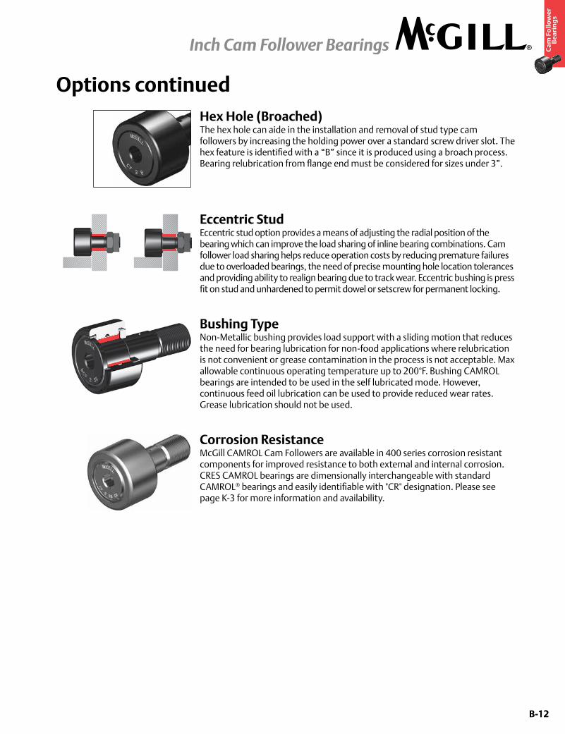
Bushing TypeNon-Metallic bushing provides load support with a sliding motion that reduces the need for bearing lubrication for non-food applications where relubrication is not convenient or grease contamination in the process is not acceptable. Max allowable continuous operating temperature up to 200°F. Bushing CAMROL bearings are intended to be used in the self lubricated mode. However, continuous feed oil lubrication can be used to provide reduced wear rates. Grease lubrication should not be used.
Eccentric StudEccentric stud option provides a means of adjusting the radial position of the bearing which can improve the load sharing of inline bearing combinations. Cam follower load sharing helps reduce operation costs by reducing premature failures due to overloaded bearings, the need of precise mounting hole location tolerances and providing ability to realign bearing due to track wear. Eccentric bushing is press fit on stud and unhardened to permit dowel or setscrew for permanent locking.
Corrosion ResistanceMcGill CAMROL Cam Followers are available in 400 series corrosion resistant components for improved resistance to both external and internal corrosion. CRES CAMROL bearings are dimensionally interchangeable with standard CAMROL® bearings and easily identifiable with "CR" designation. Please see page K-3 for more information and availability.
Hex Hole (Broached)The hex hole can aide in the installation and removal of stud type cam followers by increasing the holding power over a standard screw driver slot. The hex feature is identified with a “B” since it is produced using a broach process. Bearing relubrication from flange end must be considered for sizes under 3”.
B-13
Ca
m F
oll
ow
er
Be
ari
ng
s
Inch Cam Follower Bearings
B-13
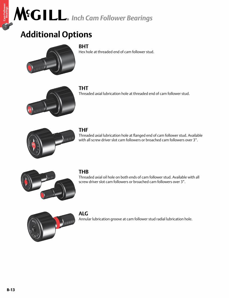
THFThreaded axial lubrication hole at flanged end of cam follower stud. Available with all screw driver slot cam followers or broached cam followers over 3”.
THBThreaded axial oil hole on both ends of cam follower stud. Available with all screw driver slot cam followers or broached cam followers over 3”.
ALGAnnular lubrication groove at cam follower stud radial lubrication hole.
Additional OptionsBHTHex hole at threaded end of cam follower stud.
THTThreaded axial lubrication hole at threaded end of cam follower stud.
B-14
Ca
m F
oll
ow
er
Be
ari
ng
s
Inch Cam Follower Bearings
B-14
Custom Capabilities• Customerspecifiedfactorygreasefill
• Greasefittinginstalled
• Studorthreadlengthmodifications
• Rollerdiametervariationsortolerances
• Camfollowersgroupedormatcheddiametertolerance/runoutsets
• Customengineeredtoorderdesigns
B-15
Ca
m F
oll
ow
er
Be
ari
ng
s
Inch Cam Follower Bearings
B-15
Part No. RD W SD SL C TL L R ECC G BDTrack Roller
Dynamic Rating
Track Roller Static Rating
Part No. HC HD F E Ro HBD
Thread Type
Clamping Torque
Limiting Speed
(Grease)
WT
W/O SealsWith
LUBRI-DISC Seals
Roller Diameter Roller Width Stud Diameter Stud Length
Endplate Extension
Min Thread Length
Length Overall
Crown Eccentric
W/O SealsWith
LUBRI-DISC Seals
Hole Center
Radial Hole Diameter
Axial Hole Dia or Fitting
Min Boss Diameter Outer Corner Housing Bore
DiameterBearing WeightPrefix
CCF-XXBase Modifier
CFE-XXinch mm
inch mm
inch mm
inch mm
inch mm
inch mm
inch mm lb/N
inch mm
inch mm
inch mm in-lb
Nm RPM lbkgNom. Tol. Nom. Tol. Nom. Tol. (Ref) (Ref) (Ref) (Ref) Radius
(Ref) (Ref) +0/-.010 ±.001 (Ref) (Ref) (Ref) (Ref) (Ref) Nom. Tol.
CF 1/2 CF 1/2 S
.500 12.70
+0/-.001 +0/-.03
.375 9.53
+0 / -.005 +0 / -.13
.190 4.83
+.001/-0 +.03/-0
.63 15.9
.031 .8
.25 6.4
1.03 26.2
Cylindrical
N/A N/A N/A 680 3,025
790 3,514
CF 1/2 CF 1/2 S
- - .125 3.175
.410 10.41
.016 .40
.1903 4.834
+.0002/-.0003 +.0005/-.0008 10-32 15
2 11,500 .04 .02
CF 1/2 B CF 1/2 SB CF 1/2 B CF 1/2 SB
CCF 1/2 CCF 1/2 S 7 178
CCF 1/2 CCF 1/2 SN/A
CCF 1/2 B CCF 1/2 SB CCF 1/2 B CCF 1/2 SB
CFE 1/2 CFE 1/2 S
.500 12.70
+0/-.001 +0/-.03
.375 9.53
+0 / -.005 +0 / -.13
.190 4.83
+.001/-0 +.03/-0
.63 15.9
.031 .8
.25 6.4
1.03 26.2
Cylindrical.010 .25
.375 9.53
.250 6.35
680 3,025
790 3,514
CFE 1/2 CFE 1/2 S
- - .125 3.175
.410 10.41
.016 .40
.253 6.42
+.001/-.001 +.025/-.025 10-32 15
2 11,500 .04 .02
CFE 1/2 B CFE 1/2 SB CFE 1/2 B CFE 1/2 SB
CCFE 1/2 CCFE 1/2 S 7 178
CCFE 1/2 CCFE 1/2 SN/A
CCFE 1/2 B CCFE 1/2 SB CCFE 1/2 B CCFE 1/2 SB
CFH 1/2 CFH 1/2 S
.500 12.70
+0/-.001 +0/-.03
.375 9.53
+0 / -.005 +0 / -.13
.190 4.83
+.001/-0 +.03/-0
.63 15.9
.031 .8
.25 6.4
1.03 26.2
Cylindrical
N/A N/A N/A 680 3,025
1,580 7,028
CFH 1/2 CFH 1/2 S
- - .125 3.175
.410 10.41
.016 .40
.2503 6.358
+.0002/-.0003 +.0005/-.0008 1/4-28 35
4 11,500 .04 .02
CFH 1/2 B CFH 1/2 SB CFH 1/2 B CFH 1/2 SB
CCFH 1/2 CCFH 1/2 S 7 178
CCFH 1/2 CCFH 1/2 SN/A
CCFH 1/2 B CCFH 1/2 SB CCFH 1/2 B CCFH 1/2 SB
CF 1/2 N CF 1/2 N S
.500 12.70
+0/-.001 +0/-.03
.344 8.74
+0 / -.005 +0 / -.13
.190 4.83
+.001/-0 +.03/-0
.50 12.7
.031 .8
.25 6.4
.88 22.2
Cylindrical
N/A N/A N/A 620 2,758
720 3,203
CF 1/2 N CF 1/2 N S
- - .125 3.175
.410 10.41
.016 .40
.1903 4.834
+.0002/-.0003 +.0005/-.0008 10-32 15
2 11,500 .04 .02
CF 1/2 N B CF 1/2 N SB CF 1/2 N B CF 1/2 N SB
CCF 1/2 N CCF 1/2 N S 6 152
CCF 1/2 N CCF 1/2 N SN/A
CCF 1/2 N B CCF 1/2 N SB CCF 1/2 N B CCF 1/2 N SB
CFE 1/2 N CFE 1/2 N S
.500 12.70
+0/-.001 +0/-.03
.344 8.74
+0 / -.005 +0 / -.13
.190 4.83
+.001/-0 +.03/-0
.50 12.7
.031 .8
.25 6.4
.88 22.2
Cylindrical.010 .25
.250 6.35
.250 6.35
620 2,758
720 3,203
CFE 1/2 N CFE 1/2 N S
- - .125 3.175
.410 10.41
.016 .40
.253 6.42
+.001/-.001 +.025/-.025 10-32 15
2 11,500 .04 .02
CFE 1/2 N B CFE 1/2 N SB CFE 1/2 N B CFE 1/2 N SB
CCFE 1/2 N CCFE 1/2 N S 6 152
CCFE 1/2 N CCFE 1/2 N SN/A
CCFE 1/2 N B CCFE 1/2 N SB CCFE 1/2 N B CCFE 1/2 N SB
CF 9/16 CF 9/16 S
.5625 14.29
+0/-.001 +0/-.03
.375 9.53
+0 / -.005 +0 / -.13
.190 4.83
+.001/-0 +.03/-0
.63 15.9
.031 .8
.25 6.4
1.03 26.2
Cylindrical
N/A N/A N/A
680 3,025
790 3,514
CF 9/16 CF 9/16 S
- - .125 3.175
.410 10.41
.016 .40
.1903 4.834
+.0002/-.0003 +.0005/-.0008
10-32 15 2 10,000 .04
.02
CF 9/16 B CF 9/16 SB CF 9/16 B CF 9/16 SB
CCF 9/16 CCF 9/16 S 7 178
CCF 9/16 CCF 9/16 SN/A
CCF 9/16 B CCF 9/16 SB CCF 9/16 B CCF 9/16 SB
CFE 9/16 CFE 9/16 S
.5625 14.29
+0/-.001 +0/-.03
.375 9.53
+0 / -.005 +0 / -.13
.190 4.83
+.001/-0 +.03/-0
.63 15.9
.031 .8
.25 6.4
1.03 26.2
Cylindrical.010 .25
.375 9.53
.250 6.35
CFE 9/16 CFE 9/16 S
- - .125 3.175
.016 .40
.253 6.42
+.001/-.001 +.025/-.025
CFE 9/16 B CFE 9/16 SB CFE 9/16 B CFE 9/16 SB
CCFE 9/16 CCFE 9/16 S 7 178
CCFE 9/16 CCFE 9/16 SN/A
CCFE 9/16 B CCFE 9/16 SB CCFE 9/16 B CCFE 9/16 SB
CFH 9/16 CFH 9/16 S
.5625 14.29
+0/-.001 +0/-.03
.375 9.53
+0 / -.005 +0 / -.13
.250 6.35
+.001/-0 +.03/-0
.63 15.9
.031 .8
.25 6.4
1.03 26.2
Cylindrical
N/A N/A N/A 680 3,025
1,580 7,028
CFH 9/16 CFH 9/16 S
- - .125 3.175
.410 10.41
.016 .40
.2503 6.358
+.0002/-.0003 +.0005/-.0008 1/4-28 35
4 10,000 .04 .02
CFH 9/16 B CFH 9/16 SB CFH 9/16 B CFH 9/16 SB
CCFH 9/16 CCFH 9/16 S 7 178
CCFH 9/16 CCFH 9/16 SN/A
CCFH 9/16 B CCFH 9/16 SB CCFH 9/16 B CCFH 9/16 SB
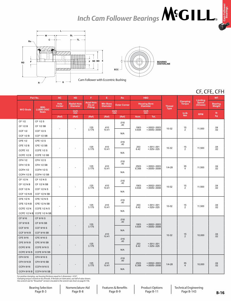
CF, CFE, CFH
HD
H
SDF
C
HC
RD
W SL
TL
E
R
Ro
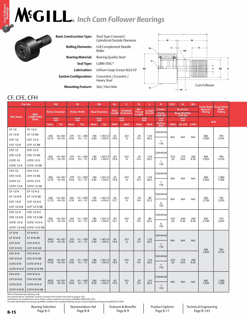
LBasic Construction Type: Stud Type Crowned /
Cylindrical Outside Diameter
Rolling Elements: Full Complement Needle Roller
Bearing Material: Bearing Quality Steel
Seal Type: LUBRI-DISC®
Lubrication: Lithium Soap Grease NLGI #2
System Configuration: Concentric / Eccentric / Heavy Stud
Mounting Feature: Slot / Hex Hole
Bearing SelectionPage B-3
Nomenclature AidPage B-8
Features & BenefitsPage B-9
Product OptionsPage B-11
Technical EngineeringPage B-143
Metric dimensions for reference only. Hex wrench size for “Broached” version is located in the wrench size chart on page B-156. Not all parts are available from stock. Please contact customer service for availability (800) 626-2120. For more information on bearing capabilities outside of our standard offering, please contact Application Engineering (800) 626-2093.
Cam Follower
B-16
Ca
m F
oll
ow
er
Be
ari
ng
s
Inch Cam Follower Bearings
B-16
Part No. RD W SD SL C TL L R ECC G BDTrack Roller
Dynamic Rating
Track Roller Static Rating
Part No. HC HD F E Ro HBD
Thread Type
Clamping Torque
Limiting Speed
(Grease)
WT
W/O SealsWith
LUBRI-DISC Seals
Roller Diameter Roller Width Stud Diameter Stud Length
Endplate Extension
Min Thread Length
Length Overall
Crown Eccentric
W/O SealsWith
LUBRI-DISC Seals
Hole Center
Radial Hole Diameter
Axial Hole Dia or Fitting
Min Boss Diameter Outer Corner Housing Bore
DiameterBearing WeightPrefix
CCF-XXBase Modifier
CFE-XXinch mm
inch mm
inch mm
inch mm
inch mm
inch mm
inch mm lb/N
inch mm
inch mm
inch mm in-lb
Nm RPM lbkgNom. Tol. Nom. Tol. Nom. Tol. (Ref) (Ref) (Ref) (Ref) Radius
(Ref) (Ref) +0/-.010 ±.001 (Ref) (Ref) (Ref) (Ref) (Ref) Nom. Tol.
CF 1/2 CF 1/2 S
.500 12.70
+0/-.001 +0/-.03
.375 9.53
+0 / -.005 +0 / -.13
.190 4.83
+.001/-0 +.03/-0
.63 15.9
.031 .8
.25 6.4
1.03 26.2
Cylindrical
N/A N/A N/A 680 3,025
790 3,514
CF 1/2 CF 1/2 S
- - .125 3.175
.410 10.41
.016 .40
.1903 4.834
+.0002/-.0003 +.0005/-.0008 10-32 15
2 11,500 .04 .02
CF 1/2 B CF 1/2 SB CF 1/2 B CF 1/2 SB
CCF 1/2 CCF 1/2 S 7 178
CCF 1/2 CCF 1/2 SN/A
CCF 1/2 B CCF 1/2 SB CCF 1/2 B CCF 1/2 SB
CFE 1/2 CFE 1/2 S
.500 12.70
+0/-.001 +0/-.03
.375 9.53
+0 / -.005 +0 / -.13
.190 4.83
+.001/-0 +.03/-0
.63 15.9
.031 .8
.25 6.4
1.03 26.2
Cylindrical.010 .25
.375 9.53
.250 6.35
680 3,025
790 3,514
CFE 1/2 CFE 1/2 S
- - .125 3.175
.410 10.41
.016 .40
.253 6.42
+.001/-.001 +.025/-.025 10-32 15
2 11,500 .04 .02
CFE 1/2 B CFE 1/2 SB CFE 1/2 B CFE 1/2 SB
CCFE 1/2 CCFE 1/2 S 7 178
CCFE 1/2 CCFE 1/2 SN/A
CCFE 1/2 B CCFE 1/2 SB CCFE 1/2 B CCFE 1/2 SB
CFH 1/2 CFH 1/2 S
.500 12.70
+0/-.001 +0/-.03
.375 9.53
+0 / -.005 +0 / -.13
.190 4.83
+.001/-0 +.03/-0
.63 15.9
.031 .8
.25 6.4
1.03 26.2
Cylindrical
N/A N/A N/A 680 3,025
1,580 7,028
CFH 1/2 CFH 1/2 S
- - .125 3.175
.410 10.41
.016 .40
.2503 6.358
+.0002/-.0003 +.0005/-.0008 1/4-28 35
4 11,500 .04 .02
CFH 1/2 B CFH 1/2 SB CFH 1/2 B CFH 1/2 SB
CCFH 1/2 CCFH 1/2 S 7 178
CCFH 1/2 CCFH 1/2 SN/A
CCFH 1/2 B CCFH 1/2 SB CCFH 1/2 B CCFH 1/2 SB
CF 1/2 N CF 1/2 N S
.500 12.70
+0/-.001 +0/-.03
.344 8.74
+0 / -.005 +0 / -.13
.190 4.83
+.001/-0 +.03/-0
.50 12.7
.031 .8
.25 6.4
.88 22.2
Cylindrical
N/A N/A N/A 620 2,758
720 3,203
CF 1/2 N CF 1/2 N S
- - .125 3.175
.410 10.41
.016 .40
.1903 4.834
+.0002/-.0003 +.0005/-.0008 10-32 15
2 11,500 .04 .02
CF 1/2 N B CF 1/2 N SB CF 1/2 N B CF 1/2 N SB
CCF 1/2 N CCF 1/2 N S 6 152
CCF 1/2 N CCF 1/2 N SN/A
CCF 1/2 N B CCF 1/2 N SB CCF 1/2 N B CCF 1/2 N SB
CFE 1/2 N CFE 1/2 N S
.500 12.70
+0/-.001 +0/-.03
.344 8.74
+0 / -.005 +0 / -.13
.190 4.83
+.001/-0 +.03/-0
.50 12.7
.031 .8
.25 6.4
.88 22.2
Cylindrical.010 .25
.250 6.35
.250 6.35
620 2,758
720 3,203
CFE 1/2 N CFE 1/2 N S
- - .125 3.175
.410 10.41
.016 .40
.253 6.42
+.001/-.001 +.025/-.025 10-32 15
2 11,500 .04 .02
CFE 1/2 N B CFE 1/2 N SB CFE 1/2 N B CFE 1/2 N SB
CCFE 1/2 N CCFE 1/2 N S 6 152
CCFE 1/2 N CCFE 1/2 N SN/A
CCFE 1/2 N B CCFE 1/2 N SB CCFE 1/2 N B CCFE 1/2 N SB
CF 9/16 CF 9/16 S
.5625 14.29
+0/-.001 +0/-.03
.375 9.53
+0 / -.005 +0 / -.13
.190 4.83
+.001/-0 +.03/-0
.63 15.9
.031 .8
.25 6.4
1.03 26.2
Cylindrical
N/A N/A N/A
680 3,025
790 3,514
CF 9/16 CF 9/16 S
- - .125 3.175
.410 10.41
.016 .40
.1903 4.834
+.0002/-.0003 +.0005/-.0008
10-32 15 2 10,000 .04
.02
CF 9/16 B CF 9/16 SB CF 9/16 B CF 9/16 SB
CCF 9/16 CCF 9/16 S 7 178
CCF 9/16 CCF 9/16 SN/A
CCF 9/16 B CCF 9/16 SB CCF 9/16 B CCF 9/16 SB
CFE 9/16 CFE 9/16 S
.5625 14.29
+0/-.001 +0/-.03
.375 9.53
+0 / -.005 +0 / -.13
.190 4.83
+.001/-0 +.03/-0
.63 15.9
.031 .8
.25 6.4
1.03 26.2
Cylindrical.010 .25
.375 9.53
.250 6.35
CFE 9/16 CFE 9/16 S
- - .125 3.175
.016 .40
.253 6.42
+.001/-.001 +.025/-.025
CFE 9/16 B CFE 9/16 SB CFE 9/16 B CFE 9/16 SB
CCFE 9/16 CCFE 9/16 S 7 178
CCFE 9/16 CCFE 9/16 SN/A
CCFE 9/16 B CCFE 9/16 SB CCFE 9/16 B CCFE 9/16 SB
CFH 9/16 CFH 9/16 S
.5625 14.29
+0/-.001 +0/-.03
.375 9.53
+0 / -.005 +0 / -.13
.250 6.35
+.001/-0 +.03/-0
.63 15.9
.031 .8
.25 6.4
1.03 26.2
Cylindrical
N/A N/A N/A 680 3,025
1,580 7,028
CFH 9/16 CFH 9/16 S
- - .125 3.175
.410 10.41
.016 .40
.2503 6.358
+.0002/-.0003 +.0005/-.0008 1/4-28 35
4 10,000 .04 .02
CFH 9/16 B CFH 9/16 SB CFH 9/16 B CFH 9/16 SB
CCFH 9/16 CCFH 9/16 S 7 178
CCFH 9/16 CCFH 9/16 SN/A
CCFH 9/16 B CCFH 9/16 SB CCFH 9/16 B CCFH 9/16 SB
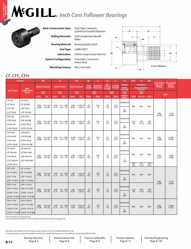
CF, CFE, CFH
CENTERLINEBEARING
ECC
F E
G
C
SL
TL
RD
W
BD
R
F SD
Ro
L
Bearing SelectionPage B-3
Nomenclature AidPage B-8
Features & BenefitsPage B-9
Product OptionsPage B-11
Technical EngineeringPage B-143
For positive clamping, use housing thickness equal to G dimension =.010”. Clamping torque is based on dry threads. If threads are lubricated, use half of value shown. Hex wrench size for “Broached” version is located in the wrench size chart on page B-156.
Cam Follower with Eccentric Bushing
B-17
Ca
m F
oll
ow
er
Be
ari
ng
s
Inch Cam Follower Bearings
B-17
CF, CFE, CFH
HD
H
SDF
C
HC
RD
W SL
TL
E
R
Ro
LBasic Construction Type: Stud Type Crowned /
Cylindrical Outside Diameter
Rolling Elements: Full Complement Needle Roller
Bearing Material: Bearing Quality Steel
Seal Type: LUBRI-DISC®
Lubrication: Lithium Soap Grease NLGI #2
System Configuration: Concentric / Eccentric / Heavy Stud
Mounting Feature: Slot / Hex Hole
Not all parts are available from stock. Please contact customer service for availability (800) 626-2120.
For more information on bearing capabilities outside of our standard offering, please contact Application Engineering (800) 626-2093.
Part No. RD W SD SL C TL L R ECC G BDTrack Roller
Dynamic Rating
Track Roller Static Rating
Part No. HC HD F E Ro HBD
Thread Type
Clamping Torque
Limiting Speed
(Grease)
WT
W/O SealsWith
LUBRI-DISC Seals
Roller Diameter Roller Width Stud Diameter Stud Length
Endplate Extension
Min Thread Length
Length Overall
Crown Eccentric
W/O SealsWith
LUBRI-DISC Seals
Hole Center
Radial Hole Diameter
Axial Hole Dia or Fitting
Min Boss Diameter Outer Corner Housing Bore
DiameterBearing WeightPrefix
CCF-XXBase Modifier
CFE-XXinch mm
inch mm
inch mm
inch mm
inch mm
inch mm
inch mm lb/N
inch mm
inch mm
inch mm in-lb
Nm RPM lbkgNom. Tol. Nom. Tol. Nom. Tol. (Ref) (Ref) (Ref) (Ref) Radius
(Ref) (Ref) +0/-.010 ±.001 (Ref) (Ref) (Ref) (Ref) (Ref) Nom. Tol.
CF 5/8 CF 5/8 S
.625 15.88
+0/-.001 +0/-.03
.438 11.11
+0 / -.005 +0 / -.13
.250 6.35
+.001/-0 +.03/-0
.75 19.1
.031 .8
.31 7.9
1.22 31.0
Cylindrical
N/A N/A N/A
955 4,248
1,215 5,404
CF 5/8 CF 5/8 S
- - .125 3.175
.462 11.73
.016 .40
.2503 6.358
+.0002/-.0003 +.0005/-.0008
1/4-28 35 4 9,200 .05
.02
CF 5/8 B CF 5/8 SB CF 5/8 B CF 5/8 SB
CCF 5/8 CCF 5/8 S 8 203
CCF 5/8 CCF 5/8 SN/A
CCF 5/8 B CCF 5/8 SB CCF 5/8 B CCF 5/8 SB
CFE 5/8 CFE 5/8 S
.625 15.88
+0/-.001 +0/-.03
.438 11.11
+0 / -.005 +0 / -.13
.250 6.35
+.001/-0 +.03/-0
.75 19.1
.031 .8
.31 7.9
1.22 31.0
Cylindrical.015 .38
.437 11.10
.375 9.53
CFE 5/8 CFE 5/8 S
- - .125 3.175
.016 .40
.378 9.60
+.001/-.001 +.025/-.025
CFE 5/8 B CFE 5/8 SB CFE 5/8 B CFE 5/8 SB
CCFE 5/8 CCFE 5/8 S 8 203
CCFE 5/8 CCFE 5/8 SN/A
CCFE 5/8 B CCFE 5/8 SB CCFE 5/8 B CCFE 5/8 SB
CFH 5/8 CFH 5/8 S
.625 15.88
+0/-.001 +0/-.03
.438 11.11
+0 / -.005 +0 / -.13
.3125 7.94
+.001/-0 +.03/-0
.75 19.1
.031 .8
.31 7.9
1.22 31.0
Cylindrical
N/A N/A N/A 955 4,248
2,480 11,031
CFH 5/8 CFH 5/8 S
- - .125 3.175
.462 11.73
.016 .40
.3128 7.945
+.0002/-.0003 +.0005/-.0008 5/16-24 90
10 9,200 .05 .02
CFH 5/8 B CFH 5/8 SB CFH 5/8 B CFH 5/8 SB
CCFH 5/8 CCFH 5/8 S 8 203
CCFH 5/8 CCFH 5/8 SN/A
CCFH 5/8 B CCFH 5/8 SB CCFH 5/8 B CCFH 5/8 SB
CF 5/8 N CF 5/8 N S
.625 15.88
+0/-.001 +0/-.03
.406 10.31
+0 / -.005 +0 / -.13
.250 6.35
+.001/-0 +.03/-0
.63 15.9
.031 .8
.31 7.9
1.06 27.0
Cylindrical
N/A N/A N/A 930 4,137
1,085 4,826
CF 5/8 N CF 5/8 N S
- - .125 3.175
.462 11.73
.016 .40
.2503 6.358
+.0002/-.0003 +.0005/-.0008 1/4-28 35
4 9,200 .05 .02
CF 5/8 N B CF 5/8 N SB CF 5/8 N B CF 5/8 N SB
CCF 5/8 N CCF 5/8 N S7
178
CCF 5/8 N CCF 5/8 N S
N/ACCF 5/8 N B CCF 5/8 N SB CCF 5/8 N B CCF 5/8 N SB
CCFE 5/8 N .015 .38
.437 11.10
.375 9.53 CCFE 5/8 N
CF 11/16 CF 11/16 S
.688 17.46
+0/-.001 +0/-.03
.438 11.11
+0 / -.005 +0 / -.13
.250 6.35
+.001/-0 +.03/-0
.75 19.1
.031 .8
.31 7.9
1.22 31.0
Cylindrical
N/A N/A N/A
955 4,248
1,215 5,404
CF 11/16 CF 11/16 S
- - .125 3.175
.462 11.73
.016 .40
.2503 6.358
+.0002/-.0003 +.0005/-.0008
1/4-28 35 4 8,300 .06
.03
CF 11/16 B CF 11/16 SB CF 11/16 B CF 11/16 SB
CCF 11/16 CCF 11/16 S 8 203
CCF 11/16 CCF 11/16 SN/A
CCF 11/16 B CCF 11/16 SB CCF 11/16 B CCF 11/16 SB
CFE 11/16 CFE 11/16 S
.688 17.46
+0/-.001 +0/-.03
.438 11.11
+0 / -.005 +0 / -.13
.250 6.35
+.001/-0 +.03/-0
.75 19.1
.031 .8
.31 7.9
1.22 31.0
Cylindrical.015 .38
.437 11.10
.375 9.53
CFE 11/16 CFE 11/16 S
- - .125 3.175
.016 .40
.378 9.60
+.001/-.001 +.025/-.025
CFE 11/16 B CFE 11/16 SB CFE 11/16 B CFE 11/16 SB
CCFE 11/16 CCFE 11/16 S 8 203
CCFE 11/16 CCFE 11/16 SN/A
CCFE 11/16 B CCFE 11/16 SB CCFE 11/16 B CCFE 11/16 SB
CFH 11/16 CFH 11/16 S
.688 17.46
+0/-.001 +0/-.03
.438 11.11
+0 / -.005 +0 / -.13
.3125 7.94
+.001/-0 +.03/-0
.75 19.1
.031 .8
.31 7.9
1.22 31.0
Cylindrical
N/A N/A N/A 955 4,248
2,480 11,031
CFH 11/16 CFH 11/16 S
- - .125 3.175
.462 11.73
.016 .40
.3128 7.945
+.0002/-.0003 +.0005/-.0008 5/16-24 90
10 8,300 .06 .03
CFH 11/16 B CFH 11/16 SB CFH 11/16 B CFH 11/16 SB
CCFH 11/16 CCFH 11/16 S 8 203
CCFH 11/16 CCFH 11/16 SN/A
CCFH 11/16 B CCFH 11/16 SB CCFH 11/16 B CCFH 11/16 SB
Cam Follower
Metric dimensions for reference only. Hex wrench size for “Broached” version is located in the wrench size chart on page B-156.
Bearing SelectionPage B-3
Nomenclature AidPage B-8
Features & BenefitsPage B-9
Product OptionsPage B-11
Technical EngineeringPage B-143
B-18
Ca
m F
oll
ow
er
Be
ari
ng
s
Inch Cam Follower Bearings
B-18
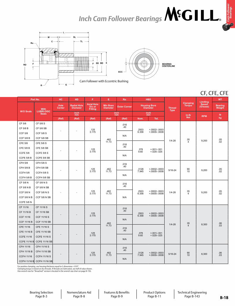
CF, CFE, CFE
CENTERLINEBEARING
ECC
F E
G
C
SL
TL
RD
W
BD
R
F SD
Ro
L
For positive clamping, use housing thickness equal to G dimension =.010”. Clamping torque is based on dry threads. If threads are lubricated, use half of value shown. Hex wrench size for “Broached” version is located in the wrench size chart on page B-156.
Part No. RD W SD SL C TL L R ECC G BDTrack Roller
Dynamic Rating
Track Roller Static Rating
Part No. HC HD F E Ro HBD
Thread Type
Clamping Torque
Limiting Speed
(Grease)
WT
W/O SealsWith
LUBRI-DISC Seals
Roller Diameter Roller Width Stud Diameter Stud Length
Endplate Extension
Min Thread Length
Length Overall
Crown Eccentric
W/O SealsWith
LUBRI-DISC Seals
Hole Center
Radial Hole Diameter
Axial Hole Dia or Fitting
Min Boss Diameter Outer Corner Housing Bore
DiameterBearing WeightPrefix
CCF-XXBase Modifier
CFE-XXinch mm
inch mm
inch mm
inch mm
inch mm
inch mm
inch mm lb/N
inch mm
inch mm
inch mm in-lb
Nm RPM lbkgNom. Tol. Nom. Tol. Nom. Tol. (Ref) (Ref) (Ref) (Ref) Radius
(Ref) (Ref) +0/-.010 ±.001 (Ref) (Ref) (Ref) (Ref) (Ref) Nom. Tol.
CF 5/8 CF 5/8 S
.625 15.88
+0/-.001 +0/-.03
.438 11.11
+0 / -.005 +0 / -.13
.250 6.35
+.001/-0 +.03/-0
.75 19.1
.031 .8
.31 7.9
1.22 31.0
Cylindrical
N/A N/A N/A
955 4,248
1,215 5,404
CF 5/8 CF 5/8 S
- - .125 3.175
.462 11.73
.016 .40
.2503 6.358
+.0002/-.0003 +.0005/-.0008
1/4-28 35 4 9,200 .05
.02
CF 5/8 B CF 5/8 SB CF 5/8 B CF 5/8 SB
CCF 5/8 CCF 5/8 S 8 203
CCF 5/8 CCF 5/8 SN/A
CCF 5/8 B CCF 5/8 SB CCF 5/8 B CCF 5/8 SB
CFE 5/8 CFE 5/8 S
.625 15.88
+0/-.001 +0/-.03
.438 11.11
+0 / -.005 +0 / -.13
.250 6.35
+.001/-0 +.03/-0
.75 19.1
.031 .8
.31 7.9
1.22 31.0
Cylindrical.015 .38
.437 11.10
.375 9.53
CFE 5/8 CFE 5/8 S
- - .125 3.175
.016 .40
.378 9.60
+.001/-.001 +.025/-.025
CFE 5/8 B CFE 5/8 SB CFE 5/8 B CFE 5/8 SB
CCFE 5/8 CCFE 5/8 S 8 203
CCFE 5/8 CCFE 5/8 SN/A
CCFE 5/8 B CCFE 5/8 SB CCFE 5/8 B CCFE 5/8 SB
CFH 5/8 CFH 5/8 S
.625 15.88
+0/-.001 +0/-.03
.438 11.11
+0 / -.005 +0 / -.13
.3125 7.94
+.001/-0 +.03/-0
.75 19.1
.031 .8
.31 7.9
1.22 31.0
Cylindrical
N/A N/A N/A 955 4,248
2,480 11,031
CFH 5/8 CFH 5/8 S
- - .125 3.175
.462 11.73
.016 .40
.3128 7.945
+.0002/-.0003 +.0005/-.0008 5/16-24 90
10 9,200 .05 .02
CFH 5/8 B CFH 5/8 SB CFH 5/8 B CFH 5/8 SB
CCFH 5/8 CCFH 5/8 S 8 203
CCFH 5/8 CCFH 5/8 SN/A
CCFH 5/8 B CCFH 5/8 SB CCFH 5/8 B CCFH 5/8 SB
CF 5/8 N CF 5/8 N S
.625 15.88
+0/-.001 +0/-.03
.406 10.31
+0 / -.005 +0 / -.13
.250 6.35
+.001/-0 +.03/-0
.63 15.9
.031 .8
.31 7.9
1.06 27.0
Cylindrical
N/A N/A N/A 930 4,137
1,085 4,826
CF 5/8 N CF 5/8 N S
- - .125 3.175
.462 11.73
.016 .40
.2503 6.358
+.0002/-.0003 +.0005/-.0008 1/4-28 35
4 9,200 .05 .02
CF 5/8 N B CF 5/8 N SB CF 5/8 N B CF 5/8 N SB
CCF 5/8 N CCF 5/8 N S7
178
CCF 5/8 N CCF 5/8 N S
N/ACCF 5/8 N B CCF 5/8 N SB CCF 5/8 N B CCF 5/8 N SB
CCFE 5/8 N .015 .38
.437 11.10
.375 9.53 CCFE 5/8 N
CF 11/16 CF 11/16 S
.688 17.46
+0/-.001 +0/-.03
.438 11.11
+0 / -.005 +0 / -.13
.250 6.35
+.001/-0 +.03/-0
.75 19.1
.031 .8
.31 7.9
1.22 31.0
Cylindrical
N/A N/A N/A
955 4,248
1,215 5,404
CF 11/16 CF 11/16 S
- - .125 3.175
.462 11.73
.016 .40
.2503 6.358
+.0002/-.0003 +.0005/-.0008
1/4-28 35 4 8,300 .06
.03
CF 11/16 B CF 11/16 SB CF 11/16 B CF 11/16 SB
CCF 11/16 CCF 11/16 S 8 203
CCF 11/16 CCF 11/16 SN/A
CCF 11/16 B CCF 11/16 SB CCF 11/16 B CCF 11/16 SB
CFE 11/16 CFE 11/16 S
.688 17.46
+0/-.001 +0/-.03
.438 11.11
+0 / -.005 +0 / -.13
.250 6.35
+.001/-0 +.03/-0
.75 19.1
.031 .8
.31 7.9
1.22 31.0
Cylindrical.015 .38
.437 11.10
.375 9.53
CFE 11/16 CFE 11/16 S
- - .125 3.175
.016 .40
.378 9.60
+.001/-.001 +.025/-.025
CFE 11/16 B CFE 11/16 SB CFE 11/16 B CFE 11/16 SB
CCFE 11/16 CCFE 11/16 S 8 203
CCFE 11/16 CCFE 11/16 SN/A
CCFE 11/16 B CCFE 11/16 SB CCFE 11/16 B CCFE 11/16 SB
CFH 11/16 CFH 11/16 S
.688 17.46
+0/-.001 +0/-.03
.438 11.11
+0 / -.005 +0 / -.13
.3125 7.94
+.001/-0 +.03/-0
.75 19.1
.031 .8
.31 7.9
1.22 31.0
Cylindrical
N/A N/A N/A 955 4,248
2,480 11,031
CFH 11/16 CFH 11/16 S
- - .125 3.175
.462 11.73
.016 .40
.3128 7.945
+.0002/-.0003 +.0005/-.0008 5/16-24 90
10 8,300 .06 .03
CFH 11/16 B CFH 11/16 SB CFH 11/16 B CFH 11/16 SB
CCFH 11/16 CCFH 11/16 S 8 203
CCFH 11/16 CCFH 11/16 SN/A
CCFH 11/16 B CCFH 11/16 SB CCFH 11/16 B CCFH 11/16 SB
Cam Follower with Eccentric Bushing
Bearing SelectionPage B-3
Nomenclature AidPage B-8
Features & BenefitsPage B-9
Product OptionsPage B-11
Technical EngineeringPage B-143

B-19
Ca
m F
oll
ow
er
Be
ari
ng
s
Inch Cam Follower Bearings
B-19
CF, CFE, CFH
HD
H
SDF
C
HC
RD
W SL
TL
E
R
Ro
LBasic Construction Type: Stud Type Crowned /
Cylindrical Outside Diameter
Rolling Elements: Full Complement Needle Roller
Bearing Material: Bearing Quality Steel
Seal Type: LUBRI-DISC®
Lubrication: Lithium Soap Grease NLGI #2
System Configuration: Concentric / Eccentric / Heavy Stud
Mounting Feature: Slot / Hex Hole
Not all parts are available from stock. Please contact customer service for availability (800) 626-2120.
For more information on bearing capabilities outside of our standard offering, please contact Application Engineering (800) 626-2093.
Part No. RD W SD SL C TL L R ECC G BDTrack Roller
Dynamic Rating
Track Roller Static Rating
Part No. HC HD F E Ro HBD
Thread Type
Clamping Torque
Limiting Speed
(Grease)
WT
W/O SealsWith
LUBRI-DISC Seals
Roller Diameter Roller Width Stud Diameter Stud Length
Endplate Extension
Min Thread Length
Length Overall
Crown Eccentric
W/O SealsWith
LUBRI-DISC Seals
Hole Center
Radial Hole Diameter
Axial Hole Dia or Fitting
Min Boss Diameter Outer Corner Housing Bore
DiameterBearing WeightPrefix
CCF-XXBase Modifier
CFE-XXinch mm
inch mm
inch mm
inch mm
inch mm
inch mm
inch mm lb/N
inch mm
inch mm
inch mm in-lb
Nm RPM lbkgNom. Tol. Nom. Tol. Nom. Tol. (Ref) (Ref) (Ref) (Ref) Radius
(Ref) (Ref) +0/-.010 ±.001 (Ref) (Ref) (Ref) (Ref) (Ref) Nom. Tol.
CF 3/4 CF 3/4 S
.750 19.05
+0/-.001 +0/-.03
.500 12.70
+0 / -.005 +0 / -.13
.375 9.53
+.001/-0 +.03/-0
.88 22.2
.031 .8
.38 9.5
1.41 35.7
Cylindrical
N/A N/A N/A
1,660 7,384
2,065 9,185
CF 3/4 CF 3/4 S
.25 6
.0938 2
.1875 5
.609 15.48
.016 .40
.3753 9.533
+.0002/-.0003 +.0005/-.0008
3/8-24 95 11 6,400 .07
.03
CF 3/4 B CF 3/4 SB CF 3/4 B CF 3/4 SB
CCF 3/4 CCF 3/4 S 10 254
CCF 3/4 CCF 3/4 SN/A
CCF 3/4 B CCF 3/4 SB CCF 3/4 B CCF 3/4 SB
CFE 3/4 CFE 3/4 S
.750 19.05
+0/-.001 +0/-.03
.500 12.70
+0 / -.005 +0 / -.13
.375 9.53
+.001/-0 +.03/-0
.88 22.2
.031 .8
.38 9.5
1.41 35.7
Cylindrical.015 .38
.500 12.70
.500 12.70
CFE 3/4 CFE 3/4 S
.25 6
.0938 2
.1875 5
.016 .40
.503 12.77
+.001/-.001 +.025/-.025
CFE 3/4 B CFE 3/4 SB CFE 3/4 B CFE 3/4 SB
CCFE 3/4 CCFE 3/4 S 10 254
CCFE 3/4 CCFE 3/4 SN/A
CCFE 3/4 B CCFE 3/4 SB CCFE 3/4 B CCFE 3/4 SB
CFH 3/4 CFH 3/4 S
.750 19.05
+0/-.001 +0/-.03
.500 12.70
+0 / -.005 +0 / -.13
.4375 11.11
+.001/-0 +.03/-0
.88 22.2
.031 .8
.38 9.5
1.41 35.7
Cylindrical
N/A N/A N/A 1,660 7,384
4,130 18,370
CFH 3/4 CFH 3/4 S
.25 6
.0938 2
.1875 5
.609 15.48
.016 .40
.4378 11.120
+.0002/-.0003 +.0005/-.0008 7/16-20 250
28 6,400 .08 .04
CFH 3/4 B CFH 3/4 SB CFH 3/4 B CFH 3/4 SB
CCFH 3/4 CCFH 3/4 S 10 254
CCFH 3/4 CCFH 3/4 SN/A
CCFH 3/4 B CCFH 3/4 SB CCFH 3/4 B CCFH 3/4 SB
CF 7/8 CF 7/8 S
.875 22.23
+0/-.001 +0/-.03
.500 12.70
+0 / -.005 +0 / -.13
.375 9.53
+.001/-0 +.03/-0
.88 22.2
.031 .8
.38 9.5
1.41 35.7
Cylindrical
N/A N/A N/A
1,660 7,384
2,065 9,185
CF 7/8 CF 7/8 S
.25 6
.0938 2
.1875 5
.609 15.48
.016 .40
.3753 9.533
+.0002/-.0003 +.0005/-.0008
3/8-24 95 11 5,400 .09
.04
CF 7/8 B CF 7/8 SB CF 7/8 B CF 7/8 SB
CCF 7/8 CCF 7/8 S 10 254
CCF 7/8 CCF 7/8 SN/A
CCF 7/8 B CCF 7/8 SB CCF 7/8 B CCF 7/8 SB
CFE 7/8 CFE 7/8 S
.875 22.23
+0/-.001 +0/-.03
.500 12.70
+0 / -.005 +0 / -.13
.375 9.53
+.001/-0 +.03/-0
.88 22.2
.031 .8
.38 9.5
1.41 35.7
Cylindrical.015 .38
.500 12.70
.500 12.70
CFE 7/8 CFE 7/8 S
.25 6
.0938 2
.1875 5
.016 .40
.503 12.77
+.001/-.001 +.025/-.025
CFE 7/8 B CFE 7/8 SB CFE 7/8 B CFE 7/8 SB
CCFE 7/8 CCFE 7/8 S 10 254
CCFE 7/8 CCFE 7/8 SN/A
CCFE 7/8 B CCFE 7/8 SB CCFE 7/8 B CCFE 7/8 SB
CFH 7/8 CFH 7/8 S
.875 22.23
+0/-.001 +0/-.03
.500 12.70
+0 / -.005 +0 / -.13
.4375 11.11
+.001/-0 +.03/-0
.88 22.2
.031 .8
.38 9.5
1.41 35.7
Cylindrical
N/A N/A N/A 1,660 7,384
4,130 18,370
CFH 7/8 CFH 7/8 S
.25 6
.0938 2
.1875 5
.609 15.48
.016 .40
.4378 11.120
+.0002/-.0003 +.0005/-.0008 7/16-20 250
28 5,400 .11 .05
CFH 7/8 B CFH 7/8 SB CFH 7/8 B CFH 7/8 SB
CCFH 7/8 CCFH 7/8 S 10 254
CCFH 7/8 CCFH 7/8 SN/A
CCFH 7/8 B CCFH 7/8 SB CCFH 7/8 B CCFH 7/8 SB
Cam Follower
Metric dimensions for reference only. Hex wrench size for “Broached” version is located in the wrench size chart on page B-156.
Bearing SelectionPage B-3
Nomenclature AidPage B-8
Features & BenefitsPage B-9
Product OptionsPage B-11
Technical EngineeringPage B-143
B-20
Ca
m F
oll
ow
er
Be
ari
ng
s
Inch Cam Follower Bearings
B-20
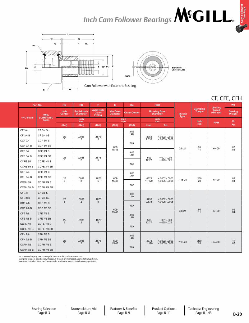
CF, CFE, CFH
CENTERLINEBEARING
ECC
F E
G
C
SL
TL
RD
W
BD
R
F SD
Ro
L
Part No. RD W SD SL C TL L R ECC G BDTrack Roller
Dynamic Rating
Track Roller Static Rating
Part No. HC HD F E Ro HBD
Thread Type
Clamping Torque
Limiting Speed
(Grease)
WT
W/O SealsWith
LUBRI-DISC Seals
Roller Diameter Roller Width Stud Diameter Stud Length
Endplate Extension
Min Thread Length
Length Overall
Crown Eccentric
W/O SealsWith
LUBRI-DISC Seals
Hole Center
Radial Hole Diameter
Axial Hole Dia or Fitting
Min Boss Diameter Outer Corner Housing Bore
DiameterBearing WeightPrefix
CCF-XXBase Modifier
CFE-XXinch mm
inch mm
inch mm
inch mm
inch mm
inch mm
inch mm lb/N
inch mm
inch mm
inch mm in-lb
Nm RPM lbkgNom. Tol. Nom. Tol. Nom. Tol. (Ref) (Ref) (Ref) (Ref) Radius
(Ref) (Ref) +0/-.010 ±.001 (Ref) (Ref) (Ref) (Ref) (Ref) Nom. Tol.
CF 3/4 CF 3/4 S
.750 19.05
+0/-.001 +0/-.03
.500 12.70
+0 / -.005 +0 / -.13
.375 9.53
+.001/-0 +.03/-0
.88 22.2
.031 .8
.38 9.5
1.41 35.7
Cylindrical
N/A N/A N/A
1,660 7,384
2,065 9,185
CF 3/4 CF 3/4 S
.25 6
.0938 2
.1875 5
.609 15.48
.016 .40
.3753 9.533
+.0002/-.0003 +.0005/-.0008
3/8-24 95 11 6,400 .07
.03
CF 3/4 B CF 3/4 SB CF 3/4 B CF 3/4 SB
CCF 3/4 CCF 3/4 S 10 254
CCF 3/4 CCF 3/4 SN/A
CCF 3/4 B CCF 3/4 SB CCF 3/4 B CCF 3/4 SB
CFE 3/4 CFE 3/4 S
.750 19.05
+0/-.001 +0/-.03
.500 12.70
+0 / -.005 +0 / -.13
.375 9.53
+.001/-0 +.03/-0
.88 22.2
.031 .8
.38 9.5
1.41 35.7
Cylindrical.015 .38
.500 12.70
.500 12.70
CFE 3/4 CFE 3/4 S
.25 6
.0938 2
.1875 5
.016 .40
.503 12.77
+.001/-.001 +.025/-.025
CFE 3/4 B CFE 3/4 SB CFE 3/4 B CFE 3/4 SB
CCFE 3/4 CCFE 3/4 S 10 254
CCFE 3/4 CCFE 3/4 SN/A
CCFE 3/4 B CCFE 3/4 SB CCFE 3/4 B CCFE 3/4 SB
CFH 3/4 CFH 3/4 S
.750 19.05
+0/-.001 +0/-.03
.500 12.70
+0 / -.005 +0 / -.13
.4375 11.11
+.001/-0 +.03/-0
.88 22.2
.031 .8
.38 9.5
1.41 35.7
Cylindrical
N/A N/A N/A 1,660 7,384
4,130 18,370
CFH 3/4 CFH 3/4 S
.25 6
.0938 2
.1875 5
.609 15.48
.016 .40
.4378 11.120
+.0002/-.0003 +.0005/-.0008 7/16-20 250
28 6,400 .08 .04
CFH 3/4 B CFH 3/4 SB CFH 3/4 B CFH 3/4 SB
CCFH 3/4 CCFH 3/4 S 10 254
CCFH 3/4 CCFH 3/4 SN/A
CCFH 3/4 B CCFH 3/4 SB CCFH 3/4 B CCFH 3/4 SB
CF 7/8 CF 7/8 S
.875 22.23
+0/-.001 +0/-.03
.500 12.70
+0 / -.005 +0 / -.13
.375 9.53
+.001/-0 +.03/-0
.88 22.2
.031 .8
.38 9.5
1.41 35.7
Cylindrical
N/A N/A N/A
1,660 7,384
2,065 9,185
CF 7/8 CF 7/8 S
.25 6
.0938 2
.1875 5
.609 15.48
.016 .40
.3753 9.533
+.0002/-.0003 +.0005/-.0008
3/8-24 95 11 5,400 .09
.04
CF 7/8 B CF 7/8 SB CF 7/8 B CF 7/8 SB
CCF 7/8 CCF 7/8 S 10 254
CCF 7/8 CCF 7/8 SN/A
CCF 7/8 B CCF 7/8 SB CCF 7/8 B CCF 7/8 SB
CFE 7/8 CFE 7/8 S
.875 22.23
+0/-.001 +0/-.03
.500 12.70
+0 / -.005 +0 / -.13
.375 9.53
+.001/-0 +.03/-0
.88 22.2
.031 .8
.38 9.5
1.41 35.7
Cylindrical.015 .38
.500 12.70
.500 12.70
CFE 7/8 CFE 7/8 S
.25 6
.0938 2
.1875 5
.016 .40
.503 12.77
+.001/-.001 +.025/-.025
CFE 7/8 B CFE 7/8 SB CFE 7/8 B CFE 7/8 SB
CCFE 7/8 CCFE 7/8 S 10 254
CCFE 7/8 CCFE 7/8 SN/A
CCFE 7/8 B CCFE 7/8 SB CCFE 7/8 B CCFE 7/8 SB
CFH 7/8 CFH 7/8 S
.875 22.23
+0/-.001 +0/-.03
.500 12.70
+0 / -.005 +0 / -.13
.4375 11.11
+.001/-0 +.03/-0
.88 22.2
.031 .8
.38 9.5
1.41 35.7
Cylindrical
N/A N/A N/A 1,660 7,384
4,130 18,370
CFH 7/8 CFH 7/8 S
.25 6
.0938 2
.1875 5
.609 15.48
.016 .40
.4378 11.120
+.0002/-.0003 +.0005/-.0008 7/16-20 250
28 5,400 .11 .05
CFH 7/8 B CFH 7/8 SB CFH 7/8 B CFH 7/8 SB
CCFH 7/8 CCFH 7/8 S 10 254
CCFH 7/8 CCFH 7/8 SN/A
CCFH 7/8 B CCFH 7/8 SB CCFH 7/8 B CCFH 7/8 SB
Cam Follower with Eccentric Bushing
For positive clamping, use housing thickness equal to G dimension =.010”. Clamping torque is based on dry threads. If threads are lubricated, use half of value shown. Hex wrench size for “Broached” version is located in the wrench size chart on page B-156.
Bearing SelectionPage B-3
Nomenclature AidPage B-8
Features & BenefitsPage B-9
Product OptionsPage B-11
Technical EngineeringPage B-143
B-21
Ca
m F
oll
ow
er
Be
ari
ng
s
Inch Cam Follower Bearings
B-21
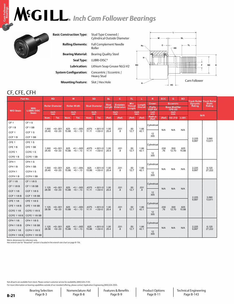
CF, CFE, CFH
HD
H
SDF
C
HC
RD
W SL
TL
E
R
Ro
LBasic Construction Type: Stud Type Crowned /
Cylindrical Outside Diameter
Rolling Elements: Full Complement Needle Roller
Bearing Material: Bearing Quality Steel
Seal Type: LUBRI-DISC®
Lubrication: Lithium Soap Grease NLGI #2
System Configuration: Concentric / Eccentric / Heavy Stud
Mounting Feature: Slot / Hex Hole
Not all parts are available from stock. Please contact customer service for availability (800) 626-2120.
For more information on bearing capabilities outside of our standard offering, please contact Application Engineering (800) 626-2093.
Part No. RD W SD SL C TL L R ECC G BDTrack Roller
Dynamic Rating
Track Roller Static Rating
Part No. HC HD F E Ro HBD
Thread Type
Clamping Torque
Limiting Speed
(Grease)
WT
W/O SealsWith
LUBRI-DISC Seals
Roller Diameter Roller Width Stud Diameter Stud Length
Endplate Extension
Min Thread Length
Length Overall
Crown Eccentric
W/O SealsWith
LUBRI-DISC Seals
Hole Center
Radial Hole Diameter
Axial Hole Dia or Fitting
Min Boss Diameter Outer Corner Housing Bore
DiameterBearing WeightPrefix
CCF-XXBase Modifier
CFE-XXinch mm
inch mm
inch mm
inch mm
inch mm
inch mm
inch mm lb/N
inch mm
inch mm
inch mm in-lb
Nm RPM lbkgNom. Tol. Nom. Tol. Nom. Tol. (Ref) (Ref) (Ref) (Ref) Radius
(Ref) (Ref) +0/-.010 ±.001 (Ref) (Ref) (Ref) (Ref) (Ref) Nom. Tol.
CF 1 CF 1 S
1.000 25.40
+0/-.001 +0/-.03
.625 15.88
+0 / -.005 +0 / -.13
.4375 11.11
+.001/-0 +.03/-0
1.00 25.4
.031 .8
.50 12.7
1.66 42.1
Cylindrical
N/A N/A N/A
2,225 9,897
3,060 13,611
CF 1 CF 1 S
.25 6
.0938 2
.1875 5
.781 19.84
.031 .79
.4378 11.120
+.0002/-.0003 +.0005/-.0008
7/16-20 250 28 4,800 .17
.08
CF 1 B CF 1 SB CF 1 B CF 1 SB
CCF 1 CCF 1 S 12 305
CCF 1 CCF 1 SN/A
CCF 1 B CCF 1 SB CCF 1 B CCF 1 SB
CFE 1 CFE 1 S
1.000 25.40
+0/-.001 +0/-.03
.625 15.88
+0 / -.005 +0 / -.13
.4375 11.11
+.001/-0 +.03/-0
1.00 25.4
.031 .8
.50 12.7
1.66 42.1
Cylindrical.030 .76
.500 12.70
.625 15.88
CFE 1 CFE 1 S
.25 6
.0938 2
.1875 5
.031 .79
.628 15.95
+.001/-.001 +.025/-.025
CFE 1 B CFE 1 SB CFE 1 B CFE 1 SB
CCFE 1 CCFE 1 S 12 305
CCFE 1 CCFE 1 SN/A
CCFE 1 B CCFE 1 SB CCFE 1 B CCFE 1 SB
CFH 1 CFH 1 S
1.000 25.40
+0/-.001 +0/-.03
.625 15.88
+0 / -.005 +0 / -.13
.625 15.88
+.001/-0 +.03/-0
1.00 25.4
.031 .8
.50 12.7
1.66 42.1
Cylindrical
N/A N/A N/A 2,225 9,897
6,120 27,222
CFH 1 CFH 1 S
.25 6
.0938 2
.1875 5
.781 19.84
.031 .79
.6253 15.883
+.0002/-.0003 +.0005/-.0008 5/8-18 650
73 4,800 .20 .09
CFH 1 B CFH 1 SB CFH 1 B CFH 1 SB
CCFH 1 CCFH 1 S 12 305
CCFH 1 CCFH 1 SN/A
CCFH 1 B CCFH 1 SB CCFH 1 B CCFH 1 SB
CF 1 1/8 CF 1 1/8 S
1.125 28.58
+0/-.001 +0/-.03
.625 15.88
+0 / -.005 +0 / -.13
.4375 11.11
+.001/-0 +.03/-0
1.00 25.4
.031 .8
.50 12.7
.031 .8
Cylindrical
N/A N/A N/A
2,225 9,897
3,060 13,611
CF 1 1/8 CF 1 1/8 S
.25 6
.0938 2
.1875 5
.781 19.84
.031 .79
.4378 11.120
+.0002/-.0003 +.0005/-.0008
7/16-20 250 28 3,400 .19
.09
CF 1 1/8 B CF 1 1/8 SB CF 1 1/8 B CF 1 1/8 SB
CCF 1 1/8 CCF 1 1/8 S 12 305
CCF 1 1/8 CCF 1 1/8 SN/A
CCF 1 1/8 B CCF 1 1/8 SB CCF 1 1/8 B CCF 1 1/8 SB
CFE 1 1/8 CFE 1 1/8 S
1.125 28.58
+0/-.001 +0/-.03
.625 15.88
+0 / -.005 +0 / -.13
.4375 11.11
+.001/-0 +.03/-0
1.00 25.4
.031 .8
.50 12.7
1.66 42.1
Cylindrical.030 .76
.500 12.70
.625 15.88
CFE 1 1/8 CFE 1 1/8 S
.25 6
.0938 2
.1875 5
.031 .79
.628 15.95
+.001/-.001 +.025/-.025
CFE 1 1/8 B CFE 1 1/8 SB CFE 1 1/8 B CFE 1 1/8 SB
CCFE 1 1/8 CCFE 1 1/8 S 12 305
CCFE 1 1/8 CCFE 1 1/8 SN/A
CCFE 1 1/8 B CCFE 1 1/8 SB CCFE 1 1/8 B CCFE 1 1/8 SB
CFH 1 1/8 CFH 1 1/8 S
1.125 28.58
+0/-.001 +0/-.03
.625 15.88
+0 / -.005 +0 / -.13
.625 15.88
+.001/-0 +.03/-0
1.00 25.4
.031 .8
.50 12.7
1.66 42.1
Cylindrical
N/A N/A N/A 2,225 9,897
6,120 27,222
CFH 1 1/8 CFH 1 1/8 S
.25 6
.0938 2
.1875 5
.781 19.84
.031 .79
.6253 15.883
+.0002/-.0003 +.0005/-.0008 5/8-18 650
73 3,400 .24 .11
CFH 1 1/8 B CFH 1 1/8 SB CFH 1 1/8 B CFH 1 1/8 SB
CCFH 1 1/8 CCFH 1 1/8 S 12 305
CCFH 1 1/8 CCFH 1 1/8 SN/A
CCFH 1 1/8 B CCFH 1 1/8 SB CCFH 1 1/8 B CCFH 1 1/8 SB
Cam Follower
Metric dimensions for reference only. Hex wrench size for “Broached” version is located in the wrench size chart on page B-156.
Bearing SelectionPage B-3
Nomenclature AidPage B-8
Features & BenefitsPage B-9
Product OptionsPage B-11
Technical EngineeringPage B-143

B-22
Ca
m F
oll
ow
er
Be
ari
ng
s
Inch Cam Follower Bearings
B-22
CF, CFE, CFH
CENTERLINEBEARING
ECC
F E
G
C
SL
TL
RD
W
BD
R
F SD
Ro
L
Part No. RD W SD SL C TL L R ECC G BDTrack Roller
Dynamic Rating
Track Roller Static Rating
Part No. HC HD F E Ro HBD
Thread Type
Clamping Torque
Limiting Speed
(Grease)
WT
W/O SealsWith
LUBRI-DISC Seals
Roller Diameter Roller Width Stud Diameter Stud Length
Endplate Extension
Min Thread Length
Length Overall
Crown Eccentric
W/O SealsWith
LUBRI-DISC Seals
Hole Center
Radial Hole Diameter
Axial Hole Dia or Fitting
Min Boss Diameter Outer Corner Housing Bore
DiameterBearing WeightPrefix
CCF-XXBase Modifier
CFE-XXinch mm
inch mm
inch mm
inch mm
inch mm
inch mm
inch mm lb/N
inch mm
inch mm
inch mm in-lb
Nm RPM lbkgNom. Tol. Nom. Tol. Nom. Tol. (Ref) (Ref) (Ref) (Ref) Radius
(Ref) (Ref) +0/-.010 ±.001 (Ref) (Ref) (Ref) (Ref) (Ref) Nom. Tol.
CF 1 CF 1 S
1.000 25.40
+0/-.001 +0/-.03
.625 15.88
+0 / -.005 +0 / -.13
.4375 11.11
+.001/-0 +.03/-0
1.00 25.4
.031 .8
.50 12.7
1.66 42.1
Cylindrical
N/A N/A N/A
2,225 9,897
3,060 13,611
CF 1 CF 1 S
.25 6
.0938 2
.1875 5
.781 19.84
.031 .79
.4378 11.120
+.0002/-.0003 +.0005/-.0008
7/16-20 250 28 4,800 .17
.08
CF 1 B CF 1 SB CF 1 B CF 1 SB
CCF 1 CCF 1 S 12 305
CCF 1 CCF 1 SN/A
CCF 1 B CCF 1 SB CCF 1 B CCF 1 SB
CFE 1 CFE 1 S
1.000 25.40
+0/-.001 +0/-.03
.625 15.88
+0 / -.005 +0 / -.13
.4375 11.11
+.001/-0 +.03/-0
1.00 25.4
.031 .8
.50 12.7
1.66 42.1
Cylindrical.030 .76
.500 12.70
.625 15.88
CFE 1 CFE 1 S
.25 6
.0938 2
.1875 5
.031 .79
.628 15.95
+.001/-.001 +.025/-.025
CFE 1 B CFE 1 SB CFE 1 B CFE 1 SB
CCFE 1 CCFE 1 S 12 305
CCFE 1 CCFE 1 SN/A
CCFE 1 B CCFE 1 SB CCFE 1 B CCFE 1 SB
CFH 1 CFH 1 S
1.000 25.40
+0/-.001 +0/-.03
.625 15.88
+0 / -.005 +0 / -.13
.625 15.88
+.001/-0 +.03/-0
1.00 25.4
.031 .8
.50 12.7
1.66 42.1
Cylindrical
N/A N/A N/A 2,225 9,897
6,120 27,222
CFH 1 CFH 1 S
.25 6
.0938 2
.1875 5
.781 19.84
.031 .79
.6253 15.883
+.0002/-.0003 +.0005/-.0008 5/8-18 650
73 4,800 .20 .09
CFH 1 B CFH 1 SB CFH 1 B CFH 1 SB
CCFH 1 CCFH 1 S 12 305
CCFH 1 CCFH 1 SN/A
CCFH 1 B CCFH 1 SB CCFH 1 B CCFH 1 SB
CF 1 1/8 CF 1 1/8 S
1.125 28.58
+0/-.001 +0/-.03
.625 15.88
+0 / -.005 +0 / -.13
.4375 11.11
+.001/-0 +.03/-0
1.00 25.4
.031 .8
.50 12.7
.031 .8
Cylindrical
N/A N/A N/A
2,225 9,897
3,060 13,611
CF 1 1/8 CF 1 1/8 S
.25 6
.0938 2
.1875 5
.781 19.84
.031 .79
.4378 11.120
+.0002/-.0003 +.0005/-.0008
7/16-20 250 28 3,400 .19
.09
CF 1 1/8 B CF 1 1/8 SB CF 1 1/8 B CF 1 1/8 SB
CCF 1 1/8 CCF 1 1/8 S 12 305
CCF 1 1/8 CCF 1 1/8 SN/A
CCF 1 1/8 B CCF 1 1/8 SB CCF 1 1/8 B CCF 1 1/8 SB
CFE 1 1/8 CFE 1 1/8 S
1.125 28.58
+0/-.001 +0/-.03
.625 15.88
+0 / -.005 +0 / -.13
.4375 11.11
+.001/-0 +.03/-0
1.00 25.4
.031 .8
.50 12.7
1.66 42.1
Cylindrical.030 .76
.500 12.70
.625 15.88
CFE 1 1/8 CFE 1 1/8 S
.25 6
.0938 2
.1875 5
.031 .79
.628 15.95
+.001/-.001 +.025/-.025
CFE 1 1/8 B CFE 1 1/8 SB CFE 1 1/8 B CFE 1 1/8 SB
CCFE 1 1/8 CCFE 1 1/8 S 12 305
CCFE 1 1/8 CCFE 1 1/8 SN/A
CCFE 1 1/8 B CCFE 1 1/8 SB CCFE 1 1/8 B CCFE 1 1/8 SB
CFH 1 1/8 CFH 1 1/8 S
1.125 28.58
+0/-.001 +0/-.03
.625 15.88
+0 / -.005 +0 / -.13
.625 15.88
+.001/-0 +.03/-0
1.00 25.4
.031 .8
.50 12.7
1.66 42.1
Cylindrical
N/A N/A N/A 2,225 9,897
6,120 27,222
CFH 1 1/8 CFH 1 1/8 S
.25 6
.0938 2
.1875 5
.781 19.84
.031 .79
.6253 15.883
+.0002/-.0003 +.0005/-.0008 5/8-18 650
73 3,400 .24 .11
CFH 1 1/8 B CFH 1 1/8 SB CFH 1 1/8 B CFH 1 1/8 SB
CCFH 1 1/8 CCFH 1 1/8 S 12 305
CCFH 1 1/8 CCFH 1 1/8 SN/A
CCFH 1 1/8 B CCFH 1 1/8 SB CCFH 1 1/8 B CCFH 1 1/8 SB
Cam Follower with Eccentric Bushing
For positive clamping, use housing thickness equal to G dimension =.010”. Clamping torque is based on dry threads. If threads are lubricated, use half of value shown. Hex wrench size for “Broached” version is located in the wrench size chart on page B-156.
Bearing SelectionPage B-3
Nomenclature AidPage B-8
Features & BenefitsPage B-9
Product OptionsPage B-11
Technical EngineeringPage B-143

B-23
Ca
m F
oll
ow
er
Be
ari
ng
s
Inch Cam Follower Bearings
B-23
CF, CFE, CFH
HD
H
SDF
C
HC
RD
W SL
TL
E
R
Ro
LBasic Construction Type: Stud Type Crowned /
Cylindrical Outside Diameter
Rolling Elements: Full Complement Needle Roller
Bearing Material: Bearing Quality Steel
Seal Type: LUBRI-DISC®
Lubrication: Lithium Soap Grease NLGI #2
System Configuration: Concentric / Eccentric / Heavy Stud
Mounting Feature: Slot / Hex Hole
Not all parts are available from stock. Please contact customer service for availability (800) 626-2120.
For more information on bearing capabilities outside of our standard offering, please contact Application Engineering (800) 626-2093.
Part No. RD W SD SL C TL L R ECC G BDTrack Roller
Dynamic Rating
Track Roller Static Rating
Part No. HC HD F E Ro HBD
Thread Type
Clamping Torque
Limiting Speed
(Grease)
WT
W/O SealsWith
LUBRI-DISC Seals
Roller Diameter Roller Width Stud Diameter Stud Length
Endplate Extension
Min Thread Length
Length Overall
Crown Eccentric
W/O SealsWith
LUBRI-DISC Seals
Hole Center
Radial Hole Diameter
Axial Hole Dia or Fitting
Min Boss Diameter Outer Corner Housing Bore
DiameterBearing WeightPrefix
CCF-XXBase Modifier
CFE-XXinch mm
inch mm
inch mm
inch mm
inch mm
inch mm
inch mm lb/N
inch mm
inch mm
inch mm in-lb
Nm RPM lbkgNom. Tol. Nom. Tol. Nom. Tol. (Ref) (Ref) (Ref) (Ref) Radius
(Ref) (Ref) +0/-.010 ±.001 (Ref) (Ref) (Ref) (Ref) (Ref) Nom. Tol.
CF 1 1/4 CF 1 1/4 S
1.250 31.75
+0/-.001 +0/-.03
.750 19.05
+0 / -.005 +0 / -.13
.500 12.70
+.001/-0 +.03/-0
1.25 31.8
.031 .8
.63 15.9
2.03 51.6
Cylindrical
N/A N/A N/A
3,930 17,481
4,250 18,904
CF 1 1/4 CF 1 1/4 S
.3125 8
.0938 2
.1875 5
.984 25.00
.031 .79
.5003 12.708
+.0002/-.0003 +.0005/-.0008
1/2-20 350 40 3,100 .30
.14
CF 1 1/4 B CF 1 1/4 SB CF 1 1/4 B CF 1 1/4 SB
CCF 1 1/4 CCF 1 1/4 S 14 356
CCF 1 1/4 CCF 1 1/4 SN/A
CCF 1 1/4 B CCF 1 1/4 SB CCF 1 1/4 B CCF 1 1/4 SB
CFE 1 1/4 CFE 1 1/4 S
1.250 31.75
+0/-.001 +0/-.03
.750 19.05
+0 / -.005 +0 / -.13
.500 12.70
+.001/-0 +.03/-0
1.25 31.8
.031 .8
.63 15.9
2.03 51.6
Cylindrical.030 .76
.625 15.88
.687 17.45
CFE 1 1/4 CFE 1 1/4 S
.3125 8
.0938 2
.1875 5
.031 .79
.690 17.52
+.001/-.001 +.025/-.025
CFE 1 1/4 B CFE 1 1/4 SB CFE 1 1/4 B CFE 1 1/4 SB
CCFE 1 1/4 CCFE 1 1/4 S 14 356
CCFE 1 1/4 CCFE 1 1/4 SN/A
CCFE 1 1/4 B CCFE 1 1/4 SB CCFE 1 1/4 B CCFE 1 1/4 SB
CFH 1 1/4 CFH 1 1/4 S
1.250 31.75
+0/-.001 +0/-.03
.750 19.05
+0 / -.005 +0 / -.13
.750 19.05
+.001/-0 +.03/-0
1.25 31.8
.031 .8
.63 15.9
2.03 51.6
Cylindrical
N/A N/A N/A 3,930 17,481
8,500 37,808
CFH 1 1/4 CFH 1 1/4 S
.3125 8
.0938 2
.1875 5
.984 25.00
.031 .79
.7503 19.058
+.0002/-.0003 +.0005/-.0008 3/4-16 1,250
141 3,100 .38 .17
CFH 1 1/4 B CFH 1 1/4 SB CFH 1 1/4 B CFH 1 1/4 SB
CCFH 1 1/4 CCFH 1 1/4 S 14 356
CCFH 1 1/4 CCFH 1 1/4 SN/A
CCFH 1 1/4 B CCFH 1 1/4 SB CCFH 1 1/4 B CCFH 1 1/4 SB
CF 1 3/8 CF 1 3/8 S
1.375 34.93
+0/-.001 +0/-.03
.750 19.05
+0 / -.005 +0 / -.13
.500 12.70
+.001/-0 +.03/-0
1.25 31.8
.031 .8
.63 15.9
2.03 51.6
Cylindrical
N/A N/A N/A
3,930 17,481
4,250 18,904
CF 1 3/8 CF 1 3/8 S
.3125 8
.0938 2
.1875 5
.984 25.00
.047 1.19
.5003 12.708
+.0002/-.0003 +.0005/-.0008
1/2-20 350 40 2,800 .35
.16
CF 1 3/8 B CF 1 3/8 SB CF 1 3/8 B CF 1 3/8 SB
CCF 1 3/8 CCF 1 3/8 S 14 356
CCF 1 3/8 CCF 1 3/8 SN/A
CCF 1 3/8 B CCF 1 3/8 SB CCF 1 3/8 B CCF 1 3/8 SB
CFE 1 3/8 CFE 1 3/8 S
1.375 34.93
+0/-.001 +0/-.03
.750 19.05
+0 / -.005 +0 / -.13
.500 12.70
+.001/-0 +.03/-0
1.25 31.8
.031 .8
.63 15.9
2.03 51.6
Cylindrical.030 .76
.625 15.88
.687 17.45
CFE 1 3/8 CFE 1 3/8 S
.3125 8
.0938 2
.1875 5
.047 1.19
.690 17.52
+.001/-.001 +.025/-.025
CFE 1 3/8 B CFE 1 3/8 SB CFE 1 3/8 B CFE 1 3/8 SB
CCFE 1 3/8 CCFE 1 3/8 S 14 356
CCFE 1 3/8 CCFE 1 3/8 SN/A
CCFE 1 3/8 B CCFE 1 3/8 SB CCFE 1 3/8 B CCFE 1 3/8 SB
CFH 1 3/8 CFH 1 3/8 S
1.375 34.93
+0/-.001 +0/-.03
.750 19.05
+0 / -.005 +0 / -.13
.750 19.05
+.001/-0 +.03/-0
1.25 31.8
.031 .8
.63 15.9
2.03 51.6
Cylindrical
N/A N/A N/A 3,930 17,481
8,500 37,808
CFH 1 3/8 CFH 1 3/8 S
.3125 8
.0938 2
.1875 5
.984 25.00
.047 1.19
.7503 19.058
+.0002/-.0003 +.0005/-.0008 3/4-16 1,250
141 2,800 .44 .19
CFH 1 3/8 B CFH 1 3/8 SB CFH 1 3/8 B CFH 1 3/8 SB
CCFH 1 3/8 CCFH 1 3/8 S 14 356
CCFH 1 3/8 CCFH 1 3/8 SN/A
CCFH 1 3/8 B CCFH 1 3/8 SB CCFH 1 3/8 B CCFH 1 3/8 SB
Cam Follower
Metric dimensions for reference only. Hex wrench size for “Broached” version is located in the wrench size chart on page B-156.
Bearing SelectionPage B-3
Nomenclature AidPage B-8
Features & BenefitsPage B-9
Product OptionsPage B-11
Technical EngineeringPage B-143
B-24
Ca
m F
oll
ow
er
Be
ari
ng
s
Inch Cam Follower Bearings
B-24
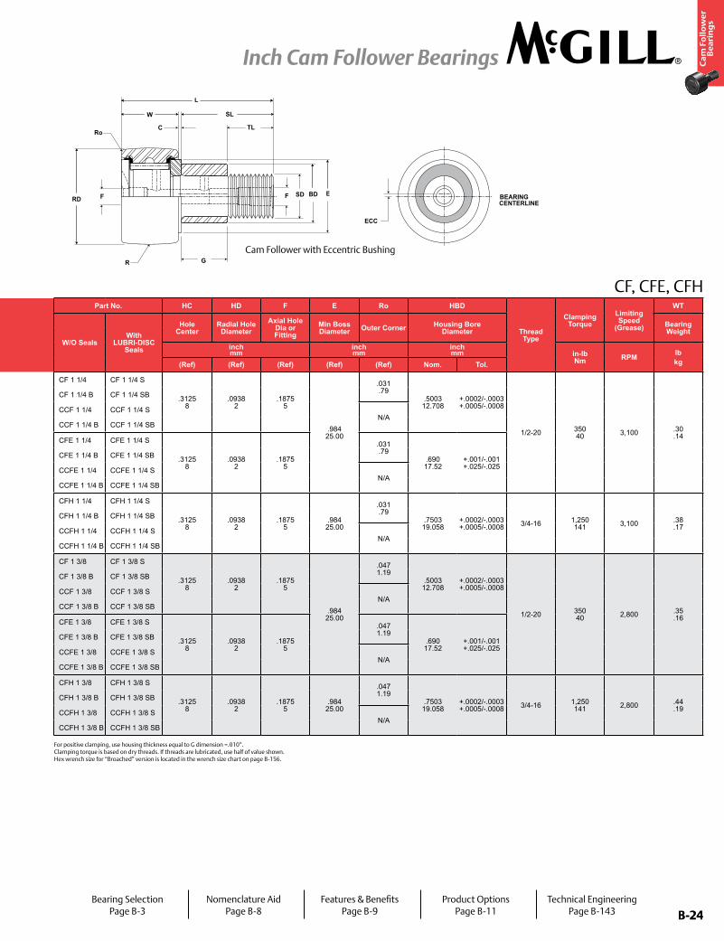
CF, CFE, CFH
CENTERLINEBEARING
ECC
F E
G
C
SL
TL
RD
W
BD
R
F SD
Ro
L
Part No. RD W SD SL C TL L R ECC G BDTrack Roller
Dynamic Rating
Track Roller Static Rating
Part No. HC HD F E Ro HBD
Thread Type
Clamping Torque
Limiting Speed
(Grease)
WT
W/O SealsWith
LUBRI-DISC Seals
Roller Diameter Roller Width Stud Diameter Stud Length
Endplate Extension
Min Thread Length
Length Overall
Crown Eccentric
W/O SealsWith
LUBRI-DISC Seals
Hole Center
Radial Hole Diameter
Axial Hole Dia or Fitting
Min Boss Diameter Outer Corner Housing Bore
DiameterBearing WeightPrefix
CCF-XXBase Modifier
CFE-XXinch mm
inch mm
inch mm
inch mm
inch mm
inch mm
inch mm lb/N
inch mm
inch mm
inch mm in-lb
Nm RPM lbkgNom. Tol. Nom. Tol. Nom. Tol. (Ref) (Ref) (Ref) (Ref) Radius
(Ref) (Ref) +0/-.010 ±.001 (Ref) (Ref) (Ref) (Ref) (Ref) Nom. Tol.
CF 1 1/4 CF 1 1/4 S
1.250 31.75
+0/-.001 +0/-.03
.750 19.05
+0 / -.005 +0 / -.13
.500 12.70
+.001/-0 +.03/-0
1.25 31.8
.031 .8
.63 15.9
2.03 51.6
Cylindrical
N/A N/A N/A
3,930 17,481
4,250 18,904
CF 1 1/4 CF 1 1/4 S
.3125 8
.0938 2
.1875 5
.984 25.00
.031 .79
.5003 12.708
+.0002/-.0003 +.0005/-.0008
1/2-20 350 40 3,100 .30
.14
CF 1 1/4 B CF 1 1/4 SB CF 1 1/4 B CF 1 1/4 SB
CCF 1 1/4 CCF 1 1/4 S 14 356
CCF 1 1/4 CCF 1 1/4 SN/A
CCF 1 1/4 B CCF 1 1/4 SB CCF 1 1/4 B CCF 1 1/4 SB
CFE 1 1/4 CFE 1 1/4 S
1.250 31.75
+0/-.001 +0/-.03
.750 19.05
+0 / -.005 +0 / -.13
.500 12.70
+.001/-0 +.03/-0
1.25 31.8
.031 .8
.63 15.9
2.03 51.6
Cylindrical.030 .76
.625 15.88
.687 17.45
CFE 1 1/4 CFE 1 1/4 S
.3125 8
.0938 2
.1875 5
.031 .79
.690 17.52
+.001/-.001 +.025/-.025
CFE 1 1/4 B CFE 1 1/4 SB CFE 1 1/4 B CFE 1 1/4 SB
CCFE 1 1/4 CCFE 1 1/4 S 14 356
CCFE 1 1/4 CCFE 1 1/4 SN/A
CCFE 1 1/4 B CCFE 1 1/4 SB CCFE 1 1/4 B CCFE 1 1/4 SB
CFH 1 1/4 CFH 1 1/4 S
1.250 31.75
+0/-.001 +0/-.03
.750 19.05
+0 / -.005 +0 / -.13
.750 19.05
+.001/-0 +.03/-0
1.25 31.8
.031 .8
.63 15.9
2.03 51.6
Cylindrical
N/A N/A N/A 3,930 17,481
8,500 37,808
CFH 1 1/4 CFH 1 1/4 S
.3125 8
.0938 2
.1875 5
.984 25.00
.031 .79
.7503 19.058
+.0002/-.0003 +.0005/-.0008 3/4-16 1,250
141 3,100 .38 .17
CFH 1 1/4 B CFH 1 1/4 SB CFH 1 1/4 B CFH 1 1/4 SB
CCFH 1 1/4 CCFH 1 1/4 S 14 356
CCFH 1 1/4 CCFH 1 1/4 SN/A
CCFH 1 1/4 B CCFH 1 1/4 SB CCFH 1 1/4 B CCFH 1 1/4 SB
CF 1 3/8 CF 1 3/8 S
1.375 34.93
+0/-.001 +0/-.03
.750 19.05
+0 / -.005 +0 / -.13
.500 12.70
+.001/-0 +.03/-0
1.25 31.8
.031 .8
.63 15.9
2.03 51.6
Cylindrical
N/A N/A N/A
3,930 17,481
4,250 18,904
CF 1 3/8 CF 1 3/8 S
.3125 8
.0938 2
.1875 5
.984 25.00
.047 1.19
.5003 12.708
+.0002/-.0003 +.0005/-.0008
1/2-20 350 40 2,800 .35
.16
CF 1 3/8 B CF 1 3/8 SB CF 1 3/8 B CF 1 3/8 SB
CCF 1 3/8 CCF 1 3/8 S 14 356
CCF 1 3/8 CCF 1 3/8 SN/A
CCF 1 3/8 B CCF 1 3/8 SB CCF 1 3/8 B CCF 1 3/8 SB
CFE 1 3/8 CFE 1 3/8 S
1.375 34.93
+0/-.001 +0/-.03
.750 19.05
+0 / -.005 +0 / -.13
.500 12.70
+.001/-0 +.03/-0
1.25 31.8
.031 .8
.63 15.9
2.03 51.6
Cylindrical.030 .76
.625 15.88
.687 17.45
CFE 1 3/8 CFE 1 3/8 S
.3125 8
.0938 2
.1875 5
.047 1.19
.690 17.52
+.001/-.001 +.025/-.025
CFE 1 3/8 B CFE 1 3/8 SB CFE 1 3/8 B CFE 1 3/8 SB
CCFE 1 3/8 CCFE 1 3/8 S 14 356
CCFE 1 3/8 CCFE 1 3/8 SN/A
CCFE 1 3/8 B CCFE 1 3/8 SB CCFE 1 3/8 B CCFE 1 3/8 SB
CFH 1 3/8 CFH 1 3/8 S
1.375 34.93
+0/-.001 +0/-.03
.750 19.05
+0 / -.005 +0 / -.13
.750 19.05
+.001/-0 +.03/-0
1.25 31.8
.031 .8
.63 15.9
2.03 51.6
Cylindrical
N/A N/A N/A 3,930 17,481
8,500 37,808
CFH 1 3/8 CFH 1 3/8 S
.3125 8
.0938 2
.1875 5
.984 25.00
.047 1.19
.7503 19.058
+.0002/-.0003 +.0005/-.0008 3/4-16 1,250
141 2,800 .44 .19
CFH 1 3/8 B CFH 1 3/8 SB CFH 1 3/8 B CFH 1 3/8 SB
CCFH 1 3/8 CCFH 1 3/8 S 14 356
CCFH 1 3/8 CCFH 1 3/8 SN/A
CCFH 1 3/8 B CCFH 1 3/8 SB CCFH 1 3/8 B CCFH 1 3/8 SB
Cam Follower with Eccentric Bushing
For positive clamping, use housing thickness equal to G dimension =.010”. Clamping torque is based on dry threads. If threads are lubricated, use half of value shown. Hex wrench size for “Broached” version is located in the wrench size chart on page B-156.
Bearing SelectionPage B-3
Nomenclature AidPage B-8
Features & BenefitsPage B-9
Product OptionsPage B-11
Technical EngineeringPage B-143

B-25
Ca
m F
oll
ow
er
Be
ari
ng
s
Inch Cam Follower Bearings
B-25
HD
H
SDF
C
HC
RD
W SL
TL
E
R
Ro
L
CF, CFE, CFH
Basic Construction Type: Stud Type Crowned / Cylindrical Outside Diameter
Rolling Elements: Full Complement Needle Roller
Bearing Material: Bearing Quality Steel
Seal Type: LUBRI-DISC®
Lubrication: Lithium Soap Grease NLGI #2
System Configuration: Concentric / Eccentric / Heavy Stud
Mounting Feature: Slot / Hex Hole
Not all parts are available from stock. Please contact customer service for availability (800) 626-2120.
For more information on bearing capabilities outside of our standard offering, please contact Application Engineering (800) 626-2093.
Part No. RD W SD SL C TL L R ECC G BDTrack Roller
Dynamic Rating
Track Roller Static Rating
Part No. HC HD F E Ro HBD
Thread Type
Clamping Torque
Limiting Speed
(Grease)
WT
W/O SealsWith
LUBRI-DISC Seals
Roller Diameter Roller Width Stud Diameter Stud Length
Endplate Extension
Min Thread Length
Length Overall
Crown Eccentric
W/O SealsWith
LUBRI-DISC Seals
Hole Center
Radial Hole Diameter
Axial Hole Dia or Fitting
Min Boss Diameter Outer Corner Housing Bore
DiameterBearing WeightPrefix
CCF-XXBase Modifier
CFE-XXinch mm
inch mm
inch mm
inch mm
inch mm
inch mm
inch mm lb/N
inch mm
inch mm
inch mm in-lb
Nm RPM lbkgNom. Tol. Nom. Tol. Nom. Tol. (Ref) (Ref) (Ref) (Ref) Radius
(Ref) (Ref) +0/-.010 ±.001 (Ref) (Ref) (Ref) (Ref) (Ref) Nom. Tol.
CF 1 1/2 CF 1 1/2 S
1.500 38.10
+0/-.001 +0/-.03
.875 22.23
+0 / -.005 +0 / -.13
.625 15.88
+.001/-0 +.03/-0
1.50 38.1
.031 .8
.75 19.1
2.41 61.1
Cylindrical
N/A N/A N/A
4,840 21,528
5,640 25,087
CF 1 1/2 CF 1 1/2 S
.375 10
.0938 2
.1875 5
1.094 27.78
.063 1.59
.6253 15.883
+.0002/-.0003 +.0005/-.0008
5/8-18 650 73 2,500 .53
.24
CF 1 1/2 B CF 1 1/2 SB CF 1 1/2 B CF 1 1/2 SB
CCF 1 1/2 CCF 1 1/2 S 20 508
CCF 1 1/2 CCF 1 1/2 SN/A
CCF 1 1/2 B CCF 1 1/2 SB CCF 1 1/2 B CCF 1 1/2 SB
CFE 1 1/2 CFE 1 1/2 S
1.500 38.10
+0/-.001 +0/-.03
.875 22.23
+0 / -.005 +0 / -.13
.625 15.88
+.001/-0 +.03/-0
1.50 38.1
.031 .8
.75 19.1
2.41 61.1
Cylindrical.030 .76
.750 19.05
875 22.23
CFE 1 1/2 CFE 1 1/2 S
.375 10
.0938 2
.1875 5
.063 1.59
.878 22.30
+.001/-.001 +.025/-.025
CFE 1 1/2 B CFE 1 1/2 SB CFE 1 1/2 B CFE 1 1/2 SB
CCFE 1 1/2 CCFE 1 1/2 S 20 508
CCFE 1 1/2 CCFE 1 1/2 SN/A
CCFE 1 1/2 B CCFE 1 1/2 SB CCFE 1 1/2 B CCFE 1 1/2 SB
CFH 1 1/2 CFH 1 1/2 S
1.500 38.10
+0/-.001 +0/-.03
.875 22.23
+0 / -.005 +0 / -.13
.875 22.23
+.001/-0 +.03/-0
1.50 38.1
.031 .8
.75 19.1
2.41 61.1
Cylindrical
N/A N/A N/A 4,840 21,528
11,280 50,173
CFH 1 1/2 CFH 1 1/2 S
.375 10
.0938 2
.1875 5
1.094 27.78
.063 1.59
.8753 22.233
+.0002/-.0003 +.0005/-.0008 7/8-14 1,500
170 2,500 .69 .31
CFH 1 1/2 B CFH 1 1/2 SB CFH 1 1/2 B CFH 1 1/2 SB
CCFH 1 1/2 CCFH 1 1/2 S 20 508
CCFH 1 1/2 CCFH 1 1/2 SN/A
CCFH 1 1/2 B CCFH 1 1/2 SB CCFH 1 1/2 B CCFH 1 1/2 SB
CF 1 5/8 CF 1 5/8 S
1.625 41.28
+0/-.001 +0/-.03
.875 22.23
+0 / -.005 +0 / -.13
.625 15.88
+.001/-0 +.03/-0
1.50 38.1
.031 .8
.75 19.1
2.41 61.1
Cylindrical
N/A N/A N/A
4,840 21,528
5,640 25,087
CF 1 5/8 CF 1 5/8 S
.375 10
.0938 2
.1875 5
1.094 27.78
.063 1.59
.6253 15.883
+.0002/-.0003 +.0005/-.0008
5/8-18 650 73 2,350 .60
.27
CF 1 5/8 B CF 1 5/8 SB CF 1 5/8 B CF 1 5/8 SB
CCF 1 5/8 CCF 1 5/8 S 20 508
CCF 1 5/8 CCF 1 5/8 SN/A
CCF 1 5/8 B CCF 1 5/8 SB CCF 1 5/8 B CCF 1 5/8 SB
CFE 1 5/8 CFE 1 5/8 S
1.625 41.28
+0/-.001 +0/-.03
.875 22.23
+0 / -.005 +0 / -.13
.625 15.88
+.001/-0 +.03/-0
1.50 38.1
.031 .8
.75 19.1
2.41 61.1
Cylindrical.030 .76
.750 19.05
.875 22.23
CFE 1 5/8 CFE 1 5/8 S
.375 10
.0938 2
.1875 5
.063 1.59
.878 22.30
+.001/-.001 +.025/-.025
CFE 1 5/8 B CFE 1 5/8 SB CFE 1 5/8 B CFE 1 5/8 SB
CCFE 1 5/8 CCFE 1 5/8 S 20 508
CCFE 1 5/8 CCFE 1 5/8 SN/A
CCFE 1 5/8 B CCFE 1 5/8 SB CCFE 1 5/8 B CCFE 1 5/8 SB
CFH 1 5/8 CFH 1 5/8 S
1.625 41.28
+0/-.001 +0/-.03
.875 22.23
+0 / -.005 +0 / -.13
.875 22.23
+.001/-0 +.03/-0
1.50 38.1
.031 .8
.75 19.1
2.41 61.1
Cylindrical
N/A N/A N/A 4,840 21,528
11,280 50,173
CFH 1 5/8 CFH 1 5/8 S
.375 10
.0938 2
.1875 5
1.094 27.78
.063 1.59
.8753 22.233
+.0002/-.0003 +.0005/-.0008 7/8-14 1,500
170 2,350 .75 .34
CFH 1 5/8 B CFH 1 5/8 SB CFH 1 5/8 B CFH 1 5/8 SB
CCFH 1 5/8 CCFH 1 5/8 S 20 508
CCFH 1 5/8 CCFH 1 5/8 SN/A
CCFH 1 5/8 B CCFH 1 5/8 SB CCFH 1 5/8 B CCFH 1 5/8 SB
Cam Follower
Metric dimensions for reference only. Hex wrench size for “Broached” version is located in the wrench size chart on page B-156.
Bearing SelectionPage B-3
Nomenclature AidPage B-8
Features & BenefitsPage B-9
Product OptionsPage B-11
Technical EngineeringPage B-143

B-26
Ca
m F
oll
ow
er
Be
ari
ng
s
Inch Cam Follower Bearings
B-26
CENTERLINEBEARING
ECC
F E
G
C
SL
TL
RD
W
BD
R
F SD
Ro
L
CF, CFE, CFHPart No. RD W SD SL C TL L R ECC G BD
Track Roller Dynamic Rating
Track Roller Static Rating
Part No. HC HD F E Ro HBD
Thread Type
Clamping Torque
Limiting Speed
(Grease)
WT
W/O SealsWith
LUBRI-DISC Seals
Roller Diameter Roller Width Stud Diameter Stud Length
Endplate Extension
Min Thread Length
Length Overall
Crown Eccentric
W/O SealsWith
LUBRI-DISC Seals
Hole Center
Radial Hole Diameter
Axial Hole Dia or Fitting
Min Boss Diameter Outer Corner Housing Bore
DiameterBearing WeightPrefix
CCF-XXBase Modifier
CFE-XXinch mm
inch mm
inch mm
inch mm
inch mm
inch mm
inch mm lb/N
inch mm
inch mm
inch mm in-lb
Nm RPM lbkgNom. Tol. Nom. Tol. Nom. Tol. (Ref) (Ref) (Ref) (Ref) Radius
(Ref) (Ref) +0/-.010 ±.001 (Ref) (Ref) (Ref) (Ref) (Ref) Nom. Tol.
CF 1 1/2 CF 1 1/2 S
1.500 38.10
+0/-.001 +0/-.03
.875 22.23
+0 / -.005 +0 / -.13
.625 15.88
+.001/-0 +.03/-0
1.50 38.1
.031 .8
.75 19.1
2.41 61.1
Cylindrical
N/A N/A N/A
4,840 21,528
5,640 25,087
CF 1 1/2 CF 1 1/2 S
.375 10
.0938 2
.1875 5
1.094 27.78
.063 1.59
.6253 15.883
+.0002/-.0003 +.0005/-.0008
5/8-18 650 73 2,500 .53
.24
CF 1 1/2 B CF 1 1/2 SB CF 1 1/2 B CF 1 1/2 SB
CCF 1 1/2 CCF 1 1/2 S 20 508
CCF 1 1/2 CCF 1 1/2 SN/A
CCF 1 1/2 B CCF 1 1/2 SB CCF 1 1/2 B CCF 1 1/2 SB
CFE 1 1/2 CFE 1 1/2 S
1.500 38.10
+0/-.001 +0/-.03
.875 22.23
+0 / -.005 +0 / -.13
.625 15.88
+.001/-0 +.03/-0
1.50 38.1
.031 .8
.75 19.1
2.41 61.1
Cylindrical.030 .76
.750 19.05
875 22.23
CFE 1 1/2 CFE 1 1/2 S
.375 10
.0938 2
.1875 5
.063 1.59
.878 22.30
+.001/-.001 +.025/-.025
CFE 1 1/2 B CFE 1 1/2 SB CFE 1 1/2 B CFE 1 1/2 SB
CCFE 1 1/2 CCFE 1 1/2 S 20 508
CCFE 1 1/2 CCFE 1 1/2 SN/A
CCFE 1 1/2 B CCFE 1 1/2 SB CCFE 1 1/2 B CCFE 1 1/2 SB
CFH 1 1/2 CFH 1 1/2 S
1.500 38.10
+0/-.001 +0/-.03
.875 22.23
+0 / -.005 +0 / -.13
.875 22.23
+.001/-0 +.03/-0
1.50 38.1
.031 .8
.75 19.1
2.41 61.1
Cylindrical
N/A N/A N/A 4,840 21,528
11,280 50,173
CFH 1 1/2 CFH 1 1/2 S
.375 10
.0938 2
.1875 5
1.094 27.78
.063 1.59
.8753 22.233
+.0002/-.0003 +.0005/-.0008 7/8-14 1,500
170 2,500 .69 .31
CFH 1 1/2 B CFH 1 1/2 SB CFH 1 1/2 B CFH 1 1/2 SB
CCFH 1 1/2 CCFH 1 1/2 S 20 508
CCFH 1 1/2 CCFH 1 1/2 SN/A
CCFH 1 1/2 B CCFH 1 1/2 SB CCFH 1 1/2 B CCFH 1 1/2 SB
CF 1 5/8 CF 1 5/8 S
1.625 41.28
+0/-.001 +0/-.03
.875 22.23
+0 / -.005 +0 / -.13
.625 15.88
+.001/-0 +.03/-0
1.50 38.1
.031 .8
.75 19.1
2.41 61.1
Cylindrical
N/A N/A N/A
4,840 21,528
5,640 25,087
CF 1 5/8 CF 1 5/8 S
.375 10
.0938 2
.1875 5
1.094 27.78
.063 1.59
.6253 15.883
+.0002/-.0003 +.0005/-.0008
5/8-18 650 73 2,350 .60
.27
CF 1 5/8 B CF 1 5/8 SB CF 1 5/8 B CF 1 5/8 SB
CCF 1 5/8 CCF 1 5/8 S 20 508
CCF 1 5/8 CCF 1 5/8 SN/A
CCF 1 5/8 B CCF 1 5/8 SB CCF 1 5/8 B CCF 1 5/8 SB
CFE 1 5/8 CFE 1 5/8 S
1.625 41.28
+0/-.001 +0/-.03
.875 22.23
+0 / -.005 +0 / -.13
.625 15.88
+.001/-0 +.03/-0
1.50 38.1
.031 .8
.75 19.1
2.41 61.1
Cylindrical.030 .76
.750 19.05
.875 22.23
CFE 1 5/8 CFE 1 5/8 S
.375 10
.0938 2
.1875 5
.063 1.59
.878 22.30
+.001/-.001 +.025/-.025
CFE 1 5/8 B CFE 1 5/8 SB CFE 1 5/8 B CFE 1 5/8 SB
CCFE 1 5/8 CCFE 1 5/8 S 20 508
CCFE 1 5/8 CCFE 1 5/8 SN/A
CCFE 1 5/8 B CCFE 1 5/8 SB CCFE 1 5/8 B CCFE 1 5/8 SB
CFH 1 5/8 CFH 1 5/8 S
1.625 41.28
+0/-.001 +0/-.03
.875 22.23
+0 / -.005 +0 / -.13
.875 22.23
+.001/-0 +.03/-0
1.50 38.1
.031 .8
.75 19.1
2.41 61.1
Cylindrical
N/A N/A N/A 4,840 21,528
11,280 50,173
CFH 1 5/8 CFH 1 5/8 S
.375 10
.0938 2
.1875 5
1.094 27.78
.063 1.59
.8753 22.233
+.0002/-.0003 +.0005/-.0008 7/8-14 1,500
170 2,350 .75 .34
CFH 1 5/8 B CFH 1 5/8 SB CFH 1 5/8 B CFH 1 5/8 SB
CCFH 1 5/8 CCFH 1 5/8 S 20 508
CCFH 1 5/8 CCFH 1 5/8 SN/A
CCFH 1 5/8 B CCFH 1 5/8 SB CCFH 1 5/8 B CCFH 1 5/8 SB
Cam Follower with Eccentric Bushing
For positive clamping, use housing thickness equal to G dimension =.010”. Clamping torque is based on dry threads. If threads are lubricated, use half of value shown. Hex wrench size for “Broached” version is located in the wrench size chart on page B-156.
Bearing SelectionPage B-3
Nomenclature AidPage B-8
Features & BenefitsPage B-9
Product OptionsPage B-11
Technical EngineeringPage B-143

B-27
Ca
m F
oll
ow
er
Be
ari
ng
s
Inch Cam Follower Bearings
B-27
HD
H
SDF
C
HC
RD
W SL
TL
E
R
Ro
L
CF, CFE, CFH
Basic Construction Type: Stud Type Crowned / Cylindrical Outside Diameter
Rolling Elements: Full Complement Needle Roller
Bearing Material: Bearing Quality Steel
Seal Type: LUBRI-DISC®
Lubrication: Lithium Soap Grease NLGI #2
System Configuration: Concentric / Eccentric / Heavy Stud
Mounting Feature: Slot / Hex Hole
Not all parts are available from stock. Please contact customer service for availability (800) 626-2120.
For more information on bearing capabilities outside of our standard offering, please contact Application Engineering (800) 626-2093.
Part No. RD W SD SL C TL L R ECC G BDTrack Roller
Dynamic Rating
Track Roller Static Rating
Part No. HC HD F E Ro HBD
Thread Type
Clamping Torque
Limiting Speed
(Grease)
WT
W/O SealsWith
LUBRI-DISC Seals
Roller Diameter Roller Width Stud Diameter Stud Length
Endplate Extension
Min Thread Length
Length Overall
Crown Eccentric
W/O SealsWith
LUBRI-DISC Seals
Hole Center
Radial Hole Diameter
Axial Hole Dia or Fitting
Min Boss Diameter Outer Corner Housing Bore
DiameterBearing WeightPrefix
CCF-XXBase Modifier
CFE-XXinch mm
inch mm
inch mm
inch mm
inch mm
inch mm
inch mm lb/N
inch mm
inch mm
inch mm in-lb
Nm RPM lbkgNom. Tol. Nom. Tol. Nom. Tol. (Ref) (Ref) (Ref) (Ref) Radius
(Ref) (Ref) +0/-.010 ±.001 (Ref) (Ref) (Ref) (Ref) (Ref) Nom. Tol.
CF 1 3/4 CF 1 3/4 S
1.750 44.45
+0/-.001 +0/-.03
1.000 25.40
+0 / -.005 +0 / -.13
.750 19.05
+.001/-0 +.03/-0
1.75 44.5
.031 .8
.88 22.2
2.78 70.6
Cylindrical
N/A N/A N/A
6,385 28,400
7,920 35,228
CF 1 3/4 CF 1 3/4 S
.4375 11
.125 3
.1875 5
1.250 31.75
.063 1.59
.7503 19.058
+.0002/-.0003 +.0005/-.0008
3/4-16 1,250 141 2,200 .84
.38
CF 1 3/4 B CF 1 3/4 SB CF 1 3/4 B CF 1 3/4 SB
CCF 1 3/4 CCF 1 3/4 S 20 508
CCF 1 3/4 CCF 1 3/4 SN/A
CCF 1 3/4 B CCF 1 3/4 SB CCF 1 3/4 B CCF 1 3/4 SB
CFE 1 3/4 CFE 1 3/4 S
1.750 44.45
+0/-.001 +0/-.03
1.000 25.40
+0 / -.005 +0 / -.13
.750 19.05
+.001/-0 +.03/-0
1.75 44.5
.031 .8
.88 22.2
2.78 70.6
Cylindrical.030 .76
.875 22.23
1.000 25.40
CFE 1 3/4 CFE 1 3/4 S
.4375 11
.125 3
.1875 5
.063 1.59
1.003 25.47
+.001/-.001 +.025/-.025
CFE 1 3/4 B CFE 1 3/4 SB CFE 1 3/4 B CFE 1 3/4 SB
CCFE 1 3/4 CCFE 1 3/4 S 20 508
CCFE 1 3/4 CCFE 1 3/4 SN/A
CCFE 1 3/4 B CCFE 1 3/4 SB CCFE 1 3/4 B CCFE 1 3/4 SB
CFH 1 3/4 CFH 1 3/4 S
1.750 44.45
+0/-.001 +0/-.03
1.000 25.40
+0 / -.005 +0 / -.13
1.000 25.40
+.001/-0 +.03/-0
1.75 44.5
.031 .8
.88 22.2
2.78 70.6
Cylindrical
N/A N/A N/A 6,385 28,400
15,840 70,456
CFH 1 3/4 CFH 1 3/4 S
.4375 11
.125 3
.1875 5
1.250 31.75
.063 1.59
1.0003 25.408
+.0002/-.0003 +.0005/-.0008 1-14 2,250
254 2,200 1.00 .45
CFH 1 3/4 B CFH 1 3/4 SB CFH 1 3/4 B CFH 1 3/4 SB
CCFH 1 3/4 CCFH 1 3/4 S 20 508
CCFH 1 3/4 CCFH 1 3/4 SN/A
CCFH 1 3/4 B CCFH 1 3/4 SB CCFH 1 3/4 B CCFH 1 3/4 SB
CF 1 7/8 CF 1 7/8 S
1.875 47.63
+0/-.001 +0/-.03
1.000 25.40
+0 / -.005 +0 / -.13
.750 19.05
+.001/-0 +.03/-0
1.75 44.5
.031 .8
.88 22.2
2.78 70.6
Cylindrical
N/A N/A N/A
6,385 28,400
7,920 35,228
CF 1 7/8 CF 1 7/8 S
.4375 11
.125 3
.1875 5
1.250 31.75
.063 1.59
.7503 19.058
+.0002/-.0003 +.0005/-.0008
3/4-16 1,250 141 2,000 .95
.43
CF 1 7/8 B CF 1 7/8 SB CF 1 7/8 B CF 1 7/8 SB
CCF 1 7/8 CCF 1 7/8 S 20 508
CCF 1 7/8 CCF 1 7/8 SN/A
CCF 1 7/8 B CCF 1 7/8 SB CCF 1 7/8 B CCF 1 7/8 SB
CFE 1 7/8 CFE 1 7/8 S
1.875 47.63
+0/-.001 +0/-.03
1.000 25.40
+0 / -.005 +0 / -.13
.750 19.05
+.001/-0 +.03/-0
1.75 44.5
.031 .8
.88 22.2
2.78 70.6
Cylindrical.030 .76
.875 22.24
1.000 25.40
CFE 1 7/8 CFE 1 7/8 S
.4375 11
.125 3
.1875 5
.063 1.59
1.003 25.47
+.001/-.001 +.025/-.025
CFE 1 7/8 B CFE 1 7/8 SB CFE 1 7/8 B CFE 1 7/8 SB
CCFE 1 7/8 CCFE 1 7/8 S 20 508
CCFE 1 7/8 CCFE 1 7/8 SN/A
CCFE 1 7/8 B CCFE 1 7/8 SB CCFE 1 7/8 B CCFE 1 7/8 SB
CFH 1 7/8 CFH 1 7/8 S
1.875 47.63
+0/-.001 +0/-.03
1.000 25.40
+0 / -.005 +0 / -.13
1.000 25.40
+.001/-0 +.03/-0
1.75 44.5
.031 .8
.88 22.2
2.78 70.6
Cylindrical
N/A N/A N/A 6,385 28,400
15,840 70,456
CFH 1 7/8 CFH 1 7/8 S
.4375 11
.125 3
.1875 5
1.250 31.75
.063 1.59
1.0003 25.408
+.0002/-.0003 +.0005/-.0008 1-14 2,250
254 2,000 1.15 .52
CFH 1 7/8 B CFH 1 7/8 SB CFH 1 7/8 B CFH 1 7/8 SB
CCFH 1 7/8 CCFH 1 7/8 S 20 508
CCFH 1 7/8 CCFH 1 7/8 SN/A
CCFH 1 7/8 B CCFH 1 7/8 SB CCFH 1 7/8 B CCFH 1 7/8 SB
Cam Follower
Metric dimensions for reference only. Hex wrench size for “Broached” version is located in the wrench size chart on page B-156.
Bearing SelectionPage B-3
Nomenclature AidPage B-8
Features & BenefitsPage B-9
Product OptionsPage B-11
Technical EngineeringPage B-143

B-28
Ca
m F
oll
ow
er
Be
ari
ng
s
Inch Cam Follower Bearings
B-28
CENTERLINEBEARING
ECC
F E
G
C
SL
TL
RD
W
BD
R
F SD
Ro
L
CF, CFE, CFHPart No. RD W SD SL C TL L R ECC G BD
Track Roller Dynamic Rating
Track Roller Static Rating
Part No. HC HD F E Ro HBD
Thread Type
Clamping Torque
Limiting Speed
(Grease)
WT
W/O SealsWith
LUBRI-DISC Seals
Roller Diameter Roller Width Stud Diameter Stud Length
Endplate Extension
Min Thread Length
Length Overall
Crown Eccentric
W/O SealsWith
LUBRI-DISC Seals
Hole Center
Radial Hole Diameter
Axial Hole Dia or Fitting
Min Boss Diameter Outer Corner Housing Bore
DiameterBearing WeightPrefix
CCF-XXBase Modifier
CFE-XXinch mm
inch mm
inch mm
inch mm
inch mm
inch mm
inch mm lb/N
inch mm
inch mm
inch mm in-lb
Nm RPM lbkgNom. Tol. Nom. Tol. Nom. Tol. (Ref) (Ref) (Ref) (Ref) Radius
(Ref) (Ref) +0/-.010 ±.001 (Ref) (Ref) (Ref) (Ref) (Ref) Nom. Tol.
CF 1 3/4 CF 1 3/4 S
1.750 44.45
+0/-.001 +0/-.03
1.000 25.40
+0 / -.005 +0 / -.13
.750 19.05
+.001/-0 +.03/-0
1.75 44.5
.031 .8
.88 22.2
2.78 70.6
Cylindrical
N/A N/A N/A
6,385 28,400
7,920 35,228
CF 1 3/4 CF 1 3/4 S
.4375 11
.125 3
.1875 5
1.250 31.75
.063 1.59
.7503 19.058
+.0002/-.0003 +.0005/-.0008
3/4-16 1,250 141 2,200 .84
.38
CF 1 3/4 B CF 1 3/4 SB CF 1 3/4 B CF 1 3/4 SB
CCF 1 3/4 CCF 1 3/4 S 20 508
CCF 1 3/4 CCF 1 3/4 SN/A
CCF 1 3/4 B CCF 1 3/4 SB CCF 1 3/4 B CCF 1 3/4 SB
CFE 1 3/4 CFE 1 3/4 S
1.750 44.45
+0/-.001 +0/-.03
1.000 25.40
+0 / -.005 +0 / -.13
.750 19.05
+.001/-0 +.03/-0
1.75 44.5
.031 .8
.88 22.2
2.78 70.6
Cylindrical.030 .76
.875 22.23
1.000 25.40
CFE 1 3/4 CFE 1 3/4 S
.4375 11
.125 3
.1875 5
.063 1.59
1.003 25.47
+.001/-.001 +.025/-.025
CFE 1 3/4 B CFE 1 3/4 SB CFE 1 3/4 B CFE 1 3/4 SB
CCFE 1 3/4 CCFE 1 3/4 S 20 508
CCFE 1 3/4 CCFE 1 3/4 SN/A
CCFE 1 3/4 B CCFE 1 3/4 SB CCFE 1 3/4 B CCFE 1 3/4 SB
CFH 1 3/4 CFH 1 3/4 S
1.750 44.45
+0/-.001 +0/-.03
1.000 25.40
+0 / -.005 +0 / -.13
1.000 25.40
+.001/-0 +.03/-0
1.75 44.5
.031 .8
.88 22.2
2.78 70.6
Cylindrical
N/A N/A N/A 6,385 28,400
15,840 70,456
CFH 1 3/4 CFH 1 3/4 S
.4375 11
.125 3
.1875 5
1.250 31.75
.063 1.59
1.0003 25.408
+.0002/-.0003 +.0005/-.0008 1-14 2,250
254 2,200 1.00 .45
CFH 1 3/4 B CFH 1 3/4 SB CFH 1 3/4 B CFH 1 3/4 SB
CCFH 1 3/4 CCFH 1 3/4 S 20 508
CCFH 1 3/4 CCFH 1 3/4 SN/A
CCFH 1 3/4 B CCFH 1 3/4 SB CCFH 1 3/4 B CCFH 1 3/4 SB
CF 1 7/8 CF 1 7/8 S
1.875 47.63
+0/-.001 +0/-.03
1.000 25.40
+0 / -.005 +0 / -.13
.750 19.05
+.001/-0 +.03/-0
1.75 44.5
.031 .8
.88 22.2
2.78 70.6
Cylindrical
N/A N/A N/A
6,385 28,400
7,920 35,228
CF 1 7/8 CF 1 7/8 S
.4375 11
.125 3
.1875 5
1.250 31.75
.063 1.59
.7503 19.058
+.0002/-.0003 +.0005/-.0008
3/4-16 1,250 141 2,000 .95
.43
CF 1 7/8 B CF 1 7/8 SB CF 1 7/8 B CF 1 7/8 SB
CCF 1 7/8 CCF 1 7/8 S 20 508
CCF 1 7/8 CCF 1 7/8 SN/A
CCF 1 7/8 B CCF 1 7/8 SB CCF 1 7/8 B CCF 1 7/8 SB
CFE 1 7/8 CFE 1 7/8 S
1.875 47.63
+0/-.001 +0/-.03
1.000 25.40
+0 / -.005 +0 / -.13
.750 19.05
+.001/-0 +.03/-0
1.75 44.5
.031 .8
.88 22.2
2.78 70.6
Cylindrical.030 .76
.875 22.24
1.000 25.40
CFE 1 7/8 CFE 1 7/8 S
.4375 11
.125 3
.1875 5
.063 1.59
1.003 25.47
+.001/-.001 +.025/-.025
CFE 1 7/8 B CFE 1 7/8 SB CFE 1 7/8 B CFE 1 7/8 SB
CCFE 1 7/8 CCFE 1 7/8 S 20 508
CCFE 1 7/8 CCFE 1 7/8 SN/A
CCFE 1 7/8 B CCFE 1 7/8 SB CCFE 1 7/8 B CCFE 1 7/8 SB
CFH 1 7/8 CFH 1 7/8 S
1.875 47.63
+0/-.001 +0/-.03
1.000 25.40
+0 / -.005 +0 / -.13
1.000 25.40
+.001/-0 +.03/-0
1.75 44.5
.031 .8
.88 22.2
2.78 70.6
Cylindrical
N/A N/A N/A 6,385 28,400
15,840 70,456
CFH 1 7/8 CFH 1 7/8 S
.4375 11
.125 3
.1875 5
1.250 31.75
.063 1.59
1.0003 25.408
+.0002/-.0003 +.0005/-.0008 1-14 2,250
254 2,000 1.15 .52
CFH 1 7/8 B CFH 1 7/8 SB CFH 1 7/8 B CFH 1 7/8 SB
CCFH 1 7/8 CCFH 1 7/8 S 20 508
CCFH 1 7/8 CCFH 1 7/8 SN/A
CCFH 1 7/8 B CCFH 1 7/8 SB CCFH 1 7/8 B CCFH 1 7/8 SB
Cam Follower with Eccentric Bushing
For positive clamping, use housing thickness equal to G dimension =.010”. Clamping torque is based on dry threads. If threads are lubricated, use half of value shown. Hex wrench size for “Broached” version is located in the wrench size chart on page B-156.
Bearing SelectionPage B-3
Nomenclature AidPage B-8
Features & BenefitsPage B-9
Product OptionsPage B-11
Technical EngineeringPage B-143

B-29
Ca
m F
oll
ow
er
Be
ari
ng
s
Inch Cam Follower Bearings
B-29
HD
H
SDF
C
HC
RD
W SL
TL
E
R
Ro
L
CF, CFE, CFH
Basic Construction Type: Stud Type Crowned / Cylindrical Outside Diameter
Rolling Elements: Full Complement Needle Roller
Bearing Material: Bearing Quality Steel
Seal Type: LUBRI-DISC®
Lubrication: Lithium Soap Grease NLGI #2
System Configuration: Concentric / Eccentric / Heavy Stud
Mounting Feature: Slot / Hex Hole
Not all parts are available from stock. Please contact customer service for availability (800) 626-2120.
For more information on bearing capabilities outside of our standard offering, please contact Application Engineering (800) 626-2093.
Part No. RD W SD SL C TL L R ECC G BDTrack Roller
Dynamic Rating
Track Roller Static Rating
Part No. HC HD F E Ro HBD
Thread Type
Clamping Torque
Limiting Speed
(Grease)
WT
W/O SealsWith
LUBRI-DISC Seals
Roller Diameter Roller Width Stud Diameter Stud Length
Endplate Extension
Min Thread Length
Length Overall
Crown Eccentric
W/O SealsWith
LUBRI-DISC Seals
Hole Center
Radial Hole Diameter
Axial Hole Dia or Fitting
Min Boss Diameter Outer Corner Housing Bore
DiameterBearing WeightPrefix
CCF-XXBase Modifier
CFE-XXinch mm
inch mm
inch mm
inch mm
inch mm
inch mm
inch mm lb/N
inch mm
inch mm
inch mm in-lb
Nm RPM lbkgNom. Tol. Nom. Tol. Nom. Tol. (Ref) (Ref) (Ref) (Ref) Radius
(Ref) (Ref) +0/-.010 ±.001 (Ref) (Ref) (Ref) (Ref) (Ref) Nom. Tol.
CF 2 CF 2 S
2.000 50.80
+0/-.001 +0/-.03
1.250 31.75
+0 / -.005 +0 / -.13
.875 22.23
+.001/-0 +.03/-0
2.00 50.8
.031 .8
1.00 25.4
3.28 83.3
Cylindrical
N/A N/A N/A
8,090 35,984
10,570 47,015
CF 2 CF 2 S
.50 13
.125 3
.1875 5
1.406 35.72
.094 2.38
.8753 22.233
+.0002/-.0003 +.0005/-.0008
7/8-14 1,500 170 1,400 1.36
.62
CF 2 B CF 2 SB CF 2 B CF 2 SB
CCF 2 CCF 2 S 24 610
CCF 2 CCF 2 SN/A
CCF 2 B CCF 2 SB CCF 2 B CCF 2 SB
CFE 2 CFE 2 S
2.000 50.80
+0/-.001 +0/-.03
1.250 31.75
+0 / -.005 +0 / -.13
.875 22.23
+.001/-0 +.03/-0
2.00 50.8
.031 .8
1.00 25.4
3.28 83.3
Cylindrical.030 .76
1.000 25.40
1.187 30.15
CFE 2 CFE 2 S
.50 13
.125 3
.1875 5
.094 2.38
1.190 30.22
+.001/-.001 +.025/-.025
CFE 2 B CFE 2 SB CFE 2 B CFE 2 SB
CCFE 2 CCFE 2 S 24 610
CCFE 2 CCFE 2 SN/A
CCFE 2 B CCFE 2 SB CCFE 2 B CCFE 2 SB
CFH 2 CFH 2 S
2.000 50.80
+0/-.001 +0/-.03
1.250 31.75
+0 / -.005 +0 / -.13
1.125 28.58
+.001/-0 +.03/-0
2.00 50.8
.031 .8
1.00 25.4
3.28 83.3
Cylindrical
N/A N/A N/A 8,090 35,984
21,140 94,031
CFH 2 CFH 2 S
.50 13
.125 3
.1875 5
1.406 35.72
.094 2.38
1.1253 28.583
+.0002/-.0003 +.0005/-.0008 1 1/8-12 2,800
316 1,400 1.56 .71
CFH 2 B CFH 2 SB CFH 2 B CFH 2 SB
CCFH 2 CCFH 2 S 24 610
CCFH 2 CCFH 2 SN/A
CCFH 2 B CCFH 2 SB CCFH 2 B CCFH 2 SB
CF 2 1/4 CF 2 1/4 S
2.250 57.15
+0/-.001 +0/-.03
1.250 31.75
+0 / -.005 +0 / -.13
.875 22.23
+.001/-0 +.03/-0
2.00 50.8
.031 .8
1.00 25.4
3.28 83.3
Cylindrical
N/A N/A N/A
8,090 35,984
10,570 47,015
CF 2 1/4 CF 2 1/4 S
.50 13
.125 3
.1875 5
1.406 35.72
.094 2.38
.8753 22.233
+.0002/-.0003 +.0005/-.0008
7/8-14 1,500 170 1,300 1.65
.75
CF 2 1/4 B CF 2 1/4 SB CF 2 1/4 B CF 2 1/4 SB
CCF 2 1/4 CCF 2 1/4 S 24 610
CCF 2 1/4 CCF 2 1/4 SN/A
CCF 2 1/4 B CCF 2 1/4 SB CCF 2 1/4 B CCF 2 1/4 SB
CFE 2 1/4 CFE 2 1/4 S
2.250 57.15
+0/-.001 +0/-.03
1.250 31.75
+0 / -.005 +0 / -.13
.875 22.23
+.001/-0 +.03/-0
2.00 50.8
.031 .8
1.00 25.4
3.28 83.3
Cylindrical.030 .76
1.000 25.40
1.187 30.15
CFE 2 1/4 CFE 2 1/4 S
.50 13
.125 3
.1875 5
.094 2.38
1.190 30.22
+.001/-.001 +.025/-.025
CFE 2 1/4 B CFE 2 1/4 SB CFE 2 1/4 B CFE 2 1/4 SB
CCFE 2 1/4 CCFE 2 1/4 S 24 610
CCFE 2 1/4 CCFE 2 1/4 SN/A
CCFE 2 1/4 B CCFE 2 1/4 SB CCFE 2 1/4 B CCFE 2 1/4 SB
CFH 2 1/4 CFH 2 1/4 S
2.250 57.15
+0/-.001 +0/-.03
1.250 31.75
+0 / -.005 +0 / -.13
1.125 28.58
+.001/-0 +.03/-0
2.00 50.8
.031 .8
1.00 25.4
3.28 83.3
Cylindrical
N/A N/A N/A 8,090 35,984
21,140 94,031
CFH 2 1/4 CFH 2 1/4 S
.50 13
.125 3
.1875 5
1.406 35.72
.094 2.38
1.1253 28.583
+.0002/-.0003 +.0005/-.0008 1 1/8-12 2,800
316 1,300 1.88 .85
CFH 2 1/4 B CFH 2 1/4 SB CFH 2 1/4 B CFH 2 1/4 SB
CCFH 2 1/4 CCFH 2 1/4 S 24 610
CCFH 2 1/4 CCFH 2 1/4 SN/A
CCFH 2 1/4 B CCFH 2 1/4 SB CCFH 2 1/4 B CCFH 2 1/4 SB
Cam Follower
Metric dimensions for reference only. Hex wrench size for “Broached” version is located in the wrench size chart on page B-156.
Bearing SelectionPage B-3
Nomenclature AidPage B-8
Features & BenefitsPage B-9
Product OptionsPage B-11
Technical EngineeringPage B-143

B-30
Ca
m F
oll
ow
er
Be
ari
ng
s
Inch Cam Follower Bearings
B-30
CENTERLINEBEARING
ECC
F E
G
C
SL
TL
RD
W
BD
R
F SD
Ro
L
CF, CFE, CFHPart No. RD W SD SL C TL L R ECC G BD
Track Roller Dynamic Rating
Track Roller Static Rating
Part No. HC HD F E Ro HBD
Thread Type
Clamping Torque
Limiting Speed
(Grease)
WT
W/O SealsWith
LUBRI-DISC Seals
Roller Diameter Roller Width Stud Diameter Stud Length
Endplate Extension
Min Thread Length
Length Overall
Crown Eccentric
W/O SealsWith
LUBRI-DISC Seals
Hole Center
Radial Hole Diameter
Axial Hole Dia or Fitting
Min Boss Diameter Outer Corner Housing Bore
DiameterBearing WeightPrefix
CCF-XXBase Modifier
CFE-XXinch mm
inch mm
inch mm
inch mm
inch mm
inch mm
inch mm lb/N
inch mm
inch mm
inch mm in-lb
Nm RPM lbkgNom. Tol. Nom. Tol. Nom. Tol. (Ref) (Ref) (Ref) (Ref) Radius
(Ref) (Ref) +0/-.010 ±.001 (Ref) (Ref) (Ref) (Ref) (Ref) Nom. Tol.
CF 2 CF 2 S
2.000 50.80
+0/-.001 +0/-.03
1.250 31.75
+0 / -.005 +0 / -.13
.875 22.23
+.001/-0 +.03/-0
2.00 50.8
.031 .8
1.00 25.4
3.28 83.3
Cylindrical
N/A N/A N/A
8,090 35,984
10,570 47,015
CF 2 CF 2 S
.50 13
.125 3
.1875 5
1.406 35.72
.094 2.38
.8753 22.233
+.0002/-.0003 +.0005/-.0008
7/8-14 1,500 170 1,400 1.36
.62
CF 2 B CF 2 SB CF 2 B CF 2 SB
CCF 2 CCF 2 S 24 610
CCF 2 CCF 2 SN/A
CCF 2 B CCF 2 SB CCF 2 B CCF 2 SB
CFE 2 CFE 2 S
2.000 50.80
+0/-.001 +0/-.03
1.250 31.75
+0 / -.005 +0 / -.13
.875 22.23
+.001/-0 +.03/-0
2.00 50.8
.031 .8
1.00 25.4
3.28 83.3
Cylindrical.030 .76
1.000 25.40
1.187 30.15
CFE 2 CFE 2 S
.50 13
.125 3
.1875 5
.094 2.38
1.190 30.22
+.001/-.001 +.025/-.025
CFE 2 B CFE 2 SB CFE 2 B CFE 2 SB
CCFE 2 CCFE 2 S 24 610
CCFE 2 CCFE 2 SN/A
CCFE 2 B CCFE 2 SB CCFE 2 B CCFE 2 SB
CFH 2 CFH 2 S
2.000 50.80
+0/-.001 +0/-.03
1.250 31.75
+0 / -.005 +0 / -.13
1.125 28.58
+.001/-0 +.03/-0
2.00 50.8
.031 .8
1.00 25.4
3.28 83.3
Cylindrical
N/A N/A N/A 8,090 35,984
21,140 94,031
CFH 2 CFH 2 S
.50 13
.125 3
.1875 5
1.406 35.72
.094 2.38
1.1253 28.583
+.0002/-.0003 +.0005/-.0008 1 1/8-12 2,800
316 1,400 1.56 .71
CFH 2 B CFH 2 SB CFH 2 B CFH 2 SB
CCFH 2 CCFH 2 S 24 610
CCFH 2 CCFH 2 SN/A
CCFH 2 B CCFH 2 SB CCFH 2 B CCFH 2 SB
CF 2 1/4 CF 2 1/4 S
2.250 57.15
+0/-.001 +0/-.03
1.250 31.75
+0 / -.005 +0 / -.13
.875 22.23
+.001/-0 +.03/-0
2.00 50.8
.031 .8
1.00 25.4
3.28 83.3
Cylindrical
N/A N/A N/A
8,090 35,984
10,570 47,015
CF 2 1/4 CF 2 1/4 S
.50 13
.125 3
.1875 5
1.406 35.72
.094 2.38
.8753 22.233
+.0002/-.0003 +.0005/-.0008
7/8-14 1,500 170 1,300 1.65
.75
CF 2 1/4 B CF 2 1/4 SB CF 2 1/4 B CF 2 1/4 SB
CCF 2 1/4 CCF 2 1/4 S 24 610
CCF 2 1/4 CCF 2 1/4 SN/A
CCF 2 1/4 B CCF 2 1/4 SB CCF 2 1/4 B CCF 2 1/4 SB
CFE 2 1/4 CFE 2 1/4 S
2.250 57.15
+0/-.001 +0/-.03
1.250 31.75
+0 / -.005 +0 / -.13
.875 22.23
+.001/-0 +.03/-0
2.00 50.8
.031 .8
1.00 25.4
3.28 83.3
Cylindrical.030 .76
1.000 25.40
1.187 30.15
CFE 2 1/4 CFE 2 1/4 S
.50 13
.125 3
.1875 5
.094 2.38
1.190 30.22
+.001/-.001 +.025/-.025
CFE 2 1/4 B CFE 2 1/4 SB CFE 2 1/4 B CFE 2 1/4 SB
CCFE 2 1/4 CCFE 2 1/4 S 24 610
CCFE 2 1/4 CCFE 2 1/4 SN/A
CCFE 2 1/4 B CCFE 2 1/4 SB CCFE 2 1/4 B CCFE 2 1/4 SB
CFH 2 1/4 CFH 2 1/4 S
2.250 57.15
+0/-.001 +0/-.03
1.250 31.75
+0 / -.005 +0 / -.13
1.125 28.58
+.001/-0 +.03/-0
2.00 50.8
.031 .8
1.00 25.4
3.28 83.3
Cylindrical
N/A N/A N/A 8,090 35,984
21,140 94,031
CFH 2 1/4 CFH 2 1/4 S
.50 13
.125 3
.1875 5
1.406 35.72
.094 2.38
1.1253 28.583
+.0002/-.0003 +.0005/-.0008 1 1/8-12 2,800
316 1,300 1.88 .85
CFH 2 1/4 B CFH 2 1/4 SB CFH 2 1/4 B CFH 2 1/4 SB
CCFH 2 1/4 CCFH 2 1/4 S 24 610
CCFH 2 1/4 CCFH 2 1/4 SN/A
CCFH 2 1/4 B CCFH 2 1/4 SB CCFH 2 1/4 B CCFH 2 1/4 SB
Cam Follower with Eccentric Bushing
For positive clamping, use housing thickness equal to G dimension =.010”. Clamping torque is based on dry threads. If threads are lubricated, use half of value shown. Hex wrench size for “Broached” version is located in the wrench size chart on page B-156.
Bearing SelectionPage B-3
Nomenclature AidPage B-8
Features & BenefitsPage B-9
Product OptionsPage B-11
Technical EngineeringPage B-143
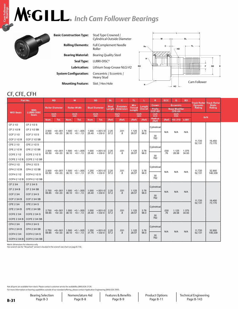
B-31
Ca
m F
oll
ow
er
Be
ari
ng
s
Inch Cam Follower Bearings
B-31
HD
H
SDF
C
HC
RD
W SL
TL
E
R
Ro
L
CF, CFE, CFH
Basic Construction Type: Stud Type Crowned / Cylindrical Outside Diameter
Rolling Elements: Full Complement Needle Roller
Bearing Material: Bearing Quality Steel
Seal Type: LUBRI-DISC®
Lubrication: Lithium Soap Grease NLGI #2
System Configuration: Concentric / Eccentric / Heavy Stud
Mounting Feature: Slot / Hex Hole
Not all parts are available from stock. Please contact customer service for availability (800) 626-2120.
For more information on bearing capabilities outside of our standard offering, please contact Application Engineering (800) 626-2093.
Part No. RD W SD SL C TL L R ECC G BDTrack Roller
Dynamic Rating
Track Roller Static Rating
Part No. HC HD F E Ro HBD
Thread Type
Clamping Torque
Limiting Speed
(Grease)
WT
W/O SealsWith
LUBRI-DISC Seals
Roller Diameter Roller Width Stud Diameter Stud Length
Endplate Extension
Min Thread Length
Length Overall
Crown Eccentric
W/O SealsWith
LUBRI-DISC Seals
Hole Center
Radial Hole Diameter
Axial Hole Dia or Fitting
Min Boss Diameter Outer Corner Housing Bore
DiameterBearing WeightPrefix
CCF-XXBase Modifier
CFE-XXinch mm
inch mm
inch mm
inch mm
inch mm
inch mm
inch mm lb/N
inch mm
inch mm
inch mm in-lb
Nm RPM lbkgNom. Tol. Nom. Tol. Nom. Tol. (Ref) (Ref) (Ref) (Ref) Radius
(Ref) (Ref) +0/-.010 ±.001 (Ref) (Ref) (Ref) (Ref) (Ref) Nom. Tol.
CF 2 1/2 CF 2 1/2 S
2.500 63.50
+0/-.001 +0/-.03
1.500 38.10
+0 / -.005 +0 / -.13
1.000 25.40
+.001/-0 +.03/-0
2.25 57.2
.031 .8
1.125 28.57
3.78 96.0
Cylindrical
N/A N/A N/A
11,720 52,131
16,450 73,170
CF 2 1/2 CF 2 1/2 S
.5625 14
.125 3
.1875 5
1.688 42.86
.094 2.38
1.0003 25.408
+.0002/-.0003 +.0005/-.0008
1-14 2,250 254 1,100 2.50
1.13
CF 2 1/2 B CF 2 1/2 SB CF 2 1/2 B CF 2 1/2 SB
CCF 2 1/2 CCF 2 1/2 S 30 762
CCF 2 1/2 CCF 2 1/2 SN/A
CCF 2 1/2 B CCF 2 1/2 SB CCF 2 1/2 B CCF 2 1/2 SB
CFE 2 1/2 CFE 2 1/2 S
2.500 63.50
+0/-.001 +0/-.03
1.500 38.10
+0 / -.005 +0 / -.13
1.000 25.40
+.001/-0 +.03/-0
2.25 57.2
.031 .8
1.125 28.57
3.78 96.0
Cylindrical.030 .76
1.125 28.58
1.375 34.93
CFE 2 1/2 CFE 2 1/2 S
.5625 14
.125 3
.1875 5
.094 2.38
1.378 35.00
+.001/-.001 +.025/-.025
CFE 2 1/2 B CFE 2 1/2 SB CFE 2 1/2 B CFE 2 1/2 SB
CCFE 2 1/2 CCFE 2 1/2 S 30 762
CCFE 2 1/2 CCFE 2 1/2 SN/A
CCFE 2 1/2 B CCFE 2 1/2 SB CCFE 2 1/2 B CCFE 2 1/2 SB
CFH 2 1/2 CFH 2 1/2 S
2.500 63.50
+0/-.001 +0/-.03
1.500 38.10
+0 / -.005 +0 / -.13
1.250 31.75
+.001/-0 +.03/-0
2.25 57.2
.031 .8
1.125 28.57
3.78 96.0
Cylindrical
N/A N/A N/A 11,720 52,131
32,900 146,339
CFH 2 1/2 CFH 2 1/2 S
.5625 14
.125 3
.1875 5
1.688 42.86
.094 2.38
1.2503 31.758
+.0002/-.0003 +.0005/-.0008 1 1/4-12 3,450
390 1,100 2.75 1.25
CFH 2 1/2 B CFH 2 1/2 SB CFH 2 1/2 B CFH 2 1/2 SB
CCFH 2 1/2 CCFH 2 1/2 S 30 762
CCFH 2 1/2 CCFH 2 1/2 SN/A
CCFH 2 1/2 B CCFH 2 1/2 SB CCFH 2 1/2 B CCFH 2 1/2 SB
CF 2 3/4 CF 2 3/4 S
2.750 69.85
+0/-.001 +0/-.03
1.500 38.10
+0 / -.005 +0 / -.13
1.000 25.40
+.001/-0 +.03/-0
2.25 57.2
.031 .8
1.125 28.57
3.78 96.0
Cylindrical
N/A N/A N/A
11,720 52,131
16,450 73,170
CF 2 3/4 CF 2 3/4 S
.5625 14
.125 3
.1875 5
1.688 42.86
.094 2.38
1.0003 25.408
+.0002/-.0003 +.0005/-.0008
1-14 2,250 254 1,050 2.93
1.33
CF 2 3/4 B CF 2 3/4 SB CF 2 3/4 B CF 2 3/4 SB
CCF 2 3/4 CCF 2 3/4 S 30 762
CCF 2 3/4 CCF 2 3/4 SN/A
CCF 2 3/4 B CCF 2 3/4 SB CCF 2 3/4 B CCF 2 3/4 SB
CFE 2 3/4 CFE 2 3/4 S
2.750 69.85
+0/-.001 +0/-.03
1.500 38.10
+0 / -.005 +0 / -.13
1.000 25.40
+.001/-0 +.03/-0
2.25 57.2
.031 .8
1.125 28.57
3.78 96.0
Cylindrical.030 .76
1.125 28.58
1.375 34.93
CFE 2 3/4 CFE 2 3/4 S
.5625 14
.125 3
.1875 5
.094 2.38
1.378 35.00
+.001/-.001 +.025/-.025
CFE 2 3/4 B CFE 2 3/4 SB CFE 2 3/4 B CFE 2 3/4 SB
CCFE 2 3/4 CCFE 2 3/4 S 30 762
CCFE 2 3/4 CCFE 2 3/4 SN/A
CCFE 2 3/4 B CCFE 2 3/4 SB CCFE 2 3/4 B CCFE 2 3/4 SB
CFH 2 3/4 CFH 2 3/4 S
2.750 69.85
+0/-.001 +0/-.03
1.500 38.10
+0 / -.005 +0 / -.13
1.250 31.75
+.001/-0 +.03/-0
2.25 57.2
.031 .8
1.125 28.57
3.78 96.0
Cylindrical
N/A N/A N/A 11,720 52,131
32,900 146,339
CFH 2 3/4 CFH 2 3/4 S
.5625 14
.125 3
.1875 5
1.688 42.86
.094 2.38
1.2503 31.758
+.0002/-.0003 +.0005/-.0008 1 1/4-12 3,450
390 1,050 3.19 1.47
CFH 2 3/4 B CFH 2 3/4 SB CFH 2 3/4 B CFH 2 3/4 SB
CCFH 2 3/4 CCFH 2 3/4 S 30 762
CCFH 2 3/4 CCFH 2 3/4 SN/A
CCFH 2 3/4 B CCFH 2 3/4 SB CCFH 2 3/4 B CCFH 2 3/4 SB
Cam Follower
Metric dimensions for reference only. Hex wrench size for “Broached” version is located in the wrench size chart on page B-156.
Bearing SelectionPage B-3
Nomenclature AidPage B-8
Features & BenefitsPage B-9
Product OptionsPage B-11
Technical EngineeringPage B-143

B-32
Ca
m F
oll
ow
er
Be
ari
ng
s
Inch Cam Follower Bearings
B-32
CENTERLINEBEARING
ECC
F E
G
C
SL
TL
RD
W
BD
R
F SD
Ro
L
CF, CFE, CFHPart No. RD W SD SL C TL L R ECC G BD
Track Roller Dynamic Rating
Track Roller Static Rating
Part No. HC HD F E Ro HBD
Thread Type
Clamping Torque
Limiting Speed
(Grease)
WT
W/O SealsWith
LUBRI-DISC Seals
Roller Diameter Roller Width Stud Diameter Stud Length
Endplate Extension
Min Thread Length
Length Overall
Crown Eccentric
W/O SealsWith
LUBRI-DISC Seals
Hole Center
Radial Hole Diameter
Axial Hole Dia or Fitting
Min Boss Diameter Outer Corner Housing Bore
DiameterBearing WeightPrefix
CCF-XXBase Modifier
CFE-XXinch mm
inch mm
inch mm
inch mm
inch mm
inch mm
inch mm lb/N
inch mm
inch mm
inch mm in-lb
Nm RPM lbkgNom. Tol. Nom. Tol. Nom. Tol. (Ref) (Ref) (Ref) (Ref) Radius
(Ref) (Ref) +0/-.010 ±.001 (Ref) (Ref) (Ref) (Ref) (Ref) Nom. Tol.
CF 2 1/2 CF 2 1/2 S
2.500 63.50
+0/-.001 +0/-.03
1.500 38.10
+0 / -.005 +0 / -.13
1.000 25.40
+.001/-0 +.03/-0
2.25 57.2
.031 .8
1.125 28.57
3.78 96.0
Cylindrical
N/A N/A N/A
11,720 52,131
16,450 73,170
CF 2 1/2 CF 2 1/2 S
.5625 14
.125 3
.1875 5
1.688 42.86
.094 2.38
1.0003 25.408
+.0002/-.0003 +.0005/-.0008
1-14 2,250 254 1,100 2.50
1.13
CF 2 1/2 B CF 2 1/2 SB CF 2 1/2 B CF 2 1/2 SB
CCF 2 1/2 CCF 2 1/2 S 30 762
CCF 2 1/2 CCF 2 1/2 SN/A
CCF 2 1/2 B CCF 2 1/2 SB CCF 2 1/2 B CCF 2 1/2 SB
CFE 2 1/2 CFE 2 1/2 S
2.500 63.50
+0/-.001 +0/-.03
1.500 38.10
+0 / -.005 +0 / -.13
1.000 25.40
+.001/-0 +.03/-0
2.25 57.2
.031 .8
1.125 28.57
3.78 96.0
Cylindrical.030 .76
1.125 28.58
1.375 34.93
CFE 2 1/2 CFE 2 1/2 S
.5625 14
.125 3
.1875 5
.094 2.38
1.378 35.00
+.001/-.001 +.025/-.025
CFE 2 1/2 B CFE 2 1/2 SB CFE 2 1/2 B CFE 2 1/2 SB
CCFE 2 1/2 CCFE 2 1/2 S 30 762
CCFE 2 1/2 CCFE 2 1/2 SN/A
CCFE 2 1/2 B CCFE 2 1/2 SB CCFE 2 1/2 B CCFE 2 1/2 SB
CFH 2 1/2 CFH 2 1/2 S
2.500 63.50
+0/-.001 +0/-.03
1.500 38.10
+0 / -.005 +0 / -.13
1.250 31.75
+.001/-0 +.03/-0
2.25 57.2
.031 .8
1.125 28.57
3.78 96.0
Cylindrical
N/A N/A N/A 11,720 52,131
32,900 146,339
CFH 2 1/2 CFH 2 1/2 S
.5625 14
.125 3
.1875 5
1.688 42.86
.094 2.38
1.2503 31.758
+.0002/-.0003 +.0005/-.0008 1 1/4-12 3,450
390 1,100 2.75 1.25
CFH 2 1/2 B CFH 2 1/2 SB CFH 2 1/2 B CFH 2 1/2 SB
CCFH 2 1/2 CCFH 2 1/2 S 30 762
CCFH 2 1/2 CCFH 2 1/2 SN/A
CCFH 2 1/2 B CCFH 2 1/2 SB CCFH 2 1/2 B CCFH 2 1/2 SB
CF 2 3/4 CF 2 3/4 S
2.750 69.85
+0/-.001 +0/-.03
1.500 38.10
+0 / -.005 +0 / -.13
1.000 25.40
+.001/-0 +.03/-0
2.25 57.2
.031 .8
1.125 28.57
3.78 96.0
Cylindrical
N/A N/A N/A
11,720 52,131
16,450 73,170
CF 2 3/4 CF 2 3/4 S
.5625 14
.125 3
.1875 5
1.688 42.86
.094 2.38
1.0003 25.408
+.0002/-.0003 +.0005/-.0008
1-14 2,250 254 1,050 2.93
1.33
CF 2 3/4 B CF 2 3/4 SB CF 2 3/4 B CF 2 3/4 SB
CCF 2 3/4 CCF 2 3/4 S 30 762
CCF 2 3/4 CCF 2 3/4 SN/A
CCF 2 3/4 B CCF 2 3/4 SB CCF 2 3/4 B CCF 2 3/4 SB
CFE 2 3/4 CFE 2 3/4 S
2.750 69.85
+0/-.001 +0/-.03
1.500 38.10
+0 / -.005 +0 / -.13
1.000 25.40
+.001/-0 +.03/-0
2.25 57.2
.031 .8
1.125 28.57
3.78 96.0
Cylindrical.030 .76
1.125 28.58
1.375 34.93
CFE 2 3/4 CFE 2 3/4 S
.5625 14
.125 3
.1875 5
.094 2.38
1.378 35.00
+.001/-.001 +.025/-.025
CFE 2 3/4 B CFE 2 3/4 SB CFE 2 3/4 B CFE 2 3/4 SB
CCFE 2 3/4 CCFE 2 3/4 S 30 762
CCFE 2 3/4 CCFE 2 3/4 SN/A
CCFE 2 3/4 B CCFE 2 3/4 SB CCFE 2 3/4 B CCFE 2 3/4 SB
CFH 2 3/4 CFH 2 3/4 S
2.750 69.85
+0/-.001 +0/-.03
1.500 38.10
+0 / -.005 +0 / -.13
1.250 31.75
+.001/-0 +.03/-0
2.25 57.2
.031 .8
1.125 28.57
3.78 96.0
Cylindrical
N/A N/A N/A 11,720 52,131
32,900 146,339
CFH 2 3/4 CFH 2 3/4 S
.5625 14
.125 3
.1875 5
1.688 42.86
.094 2.38
1.2503 31.758
+.0002/-.0003 +.0005/-.0008 1 1/4-12 3,450
390 1,050 3.19 1.47
CFH 2 3/4 B CFH 2 3/4 SB CFH 2 3/4 B CFH 2 3/4 SB
CCFH 2 3/4 CCFH 2 3/4 S 30 762
CCFH 2 3/4 CCFH 2 3/4 SN/A
CCFH 2 3/4 B CCFH 2 3/4 SB CCFH 2 3/4 B CCFH 2 3/4 SB
Cam Follower with Eccentric Bushing
For positive clamping, use housing thickness equal to G dimension =.010”. Clamping torque is based on dry threads. If threads are lubricated, use half of value shown. Hex wrench size for “Broached” version is located in the wrench size chart on page B-156.
Bearing SelectionPage B-3
Nomenclature AidPage B-8
Features & BenefitsPage B-9
Product OptionsPage B-11
Technical EngineeringPage B-143

B-33
Ca
m F
oll
ow
er
Be
ari
ng
s
Inch Cam Follower Bearings
B-33
HD
H
SDF
C
HC
RD
W SL
TL
E
R
Ro
L
CF, CFE, CFH
Basic Construction Type: Stud Type Crowned / Cylindrical Outside Diameter
Rolling Elements: Full Complement Needle Roller
Bearing Material: Bearing Quality Steel
Seal Type: LUBRI-DISC®
Lubrication: Lithium Soap Grease NLGI #2
System Configuration: Concentric / Eccentric / Heavy Stud
Mounting Feature: Slot / Hex Hole
Not all parts are available from stock. Please contact customer service for availability (800) 626-2120.
For more information on bearing capabilities outside of our standard offering, please contact Application Engineering (800) 626-2093.
Part No. RD W SD SL C TL L R ECC G BDTrack Roller
Dynamic Rating
Track Roller Static Rating
Part No. HC HD F E Ro HBD
Thread Type
Clamping Torque
Limiting Speed
(Grease)
WT
W/O SealsWith
LUBRI-DISC Seals
Roller Diameter Roller Width Stud Diameter Stud Length
Endplate Extension
Min Thread Length
Length Overall
Crown Eccentric
W/O SealsWith
LUBRI-DISC Seals
Hole Center
Radial Hole Diameter
Axial Hole Dia or Fitting
Min Boss Diameter Outer Corner Housing Bore
DiameterBearing WeightPrefix
CCF-XXBase Modifier
CFE-XXinch mm
inch mm
inch mm
inch mm
inch mm
inch mm
inch mm lb/N
inch mm
inch mm
inch mm in-lb
Nm RPM lbkgNom. Tol. Nom. Tol. Nom. Tol. (Ref) (Ref) (Ref) (Ref) Radius
(Ref) (Ref) +0/-.010 ±.001 (Ref) (Ref) (Ref) (Ref) (Ref) Nom. Tol.
CF 3 CF 3 S
3.000 76.20
+0/-.001 +0/-.03
1.750 44.45
+0 / -.005 +0 / -.13
1.250 31.75
+.001/-0 +.03/-0
2.50 63.5
.031 .8
1.25 31.75
4.28 108.7
Cylindrical
N/A N/A N/A
15,720 69,923
24,910 110,800 24,910 110,800
CF 3 CF 3 S
.625 16
.125 3
.25 * 6
2.125 53.98
.125 3.18
1.2503 31.758
+.0002/-.0003 +.0005/-.0008
1 1/4-12 3,450 390 950 4.20
1.91
CF 3 B CF 3 SB CF 3 B CF 3 SB
CCF 3 CCF 3 S 30 762
CCF 3 CCF 3 SN/A
CCF 3 B CCF 3 SB CCF 3 B CCF 3 SB
CFE 3 CFE 3 S
3.000 76.20
+0/-.001 +0/-.03
1.750 44.45
+0 / -.005 +0 / -.13
1.250 31.75
+.001/-0 +.03/-0
2.50 63.5
.031 .8
1.25 31.75
4.28 108.7
Cylindrical.060 .52
1.250 31.75
1.750 44.45
CFE 3 CFE 3 S
.625 16
.125 3
.25 * 6
.125 3.18
1.753 44.52
+.001/-.001 +.025/-.025
CFE 3 B CFE 3 SB CFE 3 B CFE 3 SB
CCFE 3 CCFE 3 S 30 762
CCFE 3 CCFE 3 SN/A
CCFE 3 B CCFE 3 SB CCFE 3 B CCFE 3 SB
CFH 3 CFH 3 S
3.000 76.20
+0/-.001 +0/-.03
1.750 44.45
+0 / -.005 +0 / -.13
1.500 38.10
+.001/-0 +.03/-0
2.50 63.5
.031 .8
1.25 31.75
4.28 108.7
Cylindrical
N/A N/A N/A 15,720 69,923
49,820 221,599
CFH 3 CFH 3 S
.625 16
.125 3
.25 * 6
2.125 53.98
.125 3.18
1.5003 38.108
+.0002/-.0003 +.0005/-.0008 1 1/2-12 5,000
565 950 4.56 2.07
CFH 3 B CFH 3 SB CFH 3 B CFH 3 SB
CCFH 3 CCFH 3 S 30 762
CCFH 3 CCFH 3 SN/A
CCFH 3 B CCFH 3 SB CCFH 3 B CCFH 3 SB
CF 3 1/4 CF 3 1/4 S
3.250 82.55
+0/-.001 +0/-.03
1.750 44.45
+0 / -.005 +0 / -.13
1.250 31.75
+.001/-0 +.03/-0
2.50 63.5
.031 .8
1.25 31.75
4.28 108.7
Cylindrical
N/A N/A N/A
15,720 69,923
24,910 110,800
CF 3 1/4 CF 3 1/4 S
.625 16
.125 3
.25 * 6
2.125 53.98
.125 3.18
1.2503 31.758
+.0002/-.0003 +.0005/-.0008
1 1/4-12 3,450 390 880 4.81
2.18
CF 3 1/4 B CF 3 1/4 SB CF 3 1/4 B CF 3 1/4 SB
CCF 3 1/4 CCF 3 1/4 S 30 762
CCF 3 1/4 CCF 3 1/4 SN/A
CCF 3 1/4 B CCF 3 1/4 SB CCF 3 1/4 B CCF 3 1/4 SB
CFE 3 1/4 CFE 3 1/4 S
3.250 82.55
+0/-.001 +0/-.03
1.750 44.45
+0 / -.005 +0 / -.13
1.250 31.75
+.001/-0 +.03/-0
2.50 63.5
.031 .8
1.25 31.75
4.28 108.7
Cylindrical.060 .52
1.250 31.75
1.750 44.45
CFE 3 1/4 CFE 3 1/4 S
.625 16
.125 3
.25 * 6
.125 3.18
1.753 44.52
+.001/-.001 +.025/-.025
CFE 3 1/4 B CFE 3 1/4 SB CFE 3 1/4 B CFE 3 1/4 SB
CCFE 3 1/4 CCFE 3 1/4 S 30 762
CCFE 3 1/4 CCFE 3 1/4 SN/A
CCFE 3 1/4 B CCFE 3 1/4 SB CCFE 3 1/4 B CCFE 3 1/4 SB
CFH 3 1/4 CFH 3 1/4 S
3.250 82.55
+0/-.001 +0/-.03
1.750 44.45
+0 / -.005 +0 / -.13
1.500 38.10
+.001/-0 +.03/-0
2.50 63.5
.031 .8
1.25 31.75
4.28 108.7
Cylindrical
N/A N/A N/A 15,720 69,923
49,820 221,599
CFH 3 1/4 CFH 3 1/4 S
.625 16
.125 3
.25 * 6
2.125 53.98
.125 3.18
1.5003 38.108
+.0002/-.0003 +.0005/-.0008 1 1/2-12 5,000
565 880 5.19 2.35
CFH 3 1/4 B CFH 3 1/4 SB CFH 3 1/4 B CFH 3 1/4 SB
CCFH 3 1/4 CCFH 3 1/4 S 30 762
CCFH 3 1/4 CCFH 3 1/4 SN/A
CCFH 3 1/4 B CCFH 3 1/4 SB CCFH 3 1/4 B CCFH 3 1/4 SB
Cam Follower
Metric dimensions for reference only. Hex wrench size for “Broached” version is located in the wrench size chart on page B-156.
Bearing SelectionPage B-3
Nomenclature AidPage B-8
Features & BenefitsPage B-9
Product OptionsPage B-11
Technical EngineeringPage B-143

B-34
Ca
m F
oll
ow
er
Be
ari
ng
s
Inch Cam Follower Bearings
B-34
CENTERLINEBEARING
ECC
F E
G
C
SL
TL
RD
W
BD
R
F SD
Ro
L
CF, CFE, CFH
* Lubrication hole (F) at bottom of hex hole and 1/4 inch straight drive fitting will ball check supplied but not installed. For positive clamping, use housing thickness equal to G dimension =.010”. Clamping torque is based on dry threads. If threads are lubricated, use half of value shown. Hex wrench size for “Broached” version is located in the wrench size chart on page B-156.
Part No. RD W SD SL C TL L R ECC G BDTrack Roller
Dynamic Rating
Track Roller Static Rating
Part No. HC HD F E Ro HBD
Thread Type
Clamping Torque
Limiting Speed
(Grease)
WT
W/O SealsWith
LUBRI-DISC Seals
Roller Diameter Roller Width Stud Diameter Stud Length
Endplate Extension
Min Thread Length
Length Overall
Crown Eccentric
W/O SealsWith
LUBRI-DISC Seals
Hole Center
Radial Hole Diameter
Axial Hole Dia or Fitting
Min Boss Diameter Outer Corner Housing Bore
DiameterBearing WeightPrefix
CCF-XXBase Modifier
CFE-XXinch mm
inch mm
inch mm
inch mm
inch mm
inch mm
inch mm lb/N
inch mm
inch mm
inch mm in-lb
Nm RPM lbkgNom. Tol. Nom. Tol. Nom. Tol. (Ref) (Ref) (Ref) (Ref) Radius
(Ref) (Ref) +0/-.010 ±.001 (Ref) (Ref) (Ref) (Ref) (Ref) Nom. Tol.
CF 3 CF 3 S
3.000 76.20
+0/-.001 +0/-.03
1.750 44.45
+0 / -.005 +0 / -.13
1.250 31.75
+.001/-0 +.03/-0
2.50 63.5
.031 .8
1.25 31.75
4.28 108.7
Cylindrical
N/A N/A N/A
15,720 69,923
24,910 110,800 24,910 110,800
CF 3 CF 3 S
.625 16
.125 3
.25 * 6
2.125 53.98
.125 3.18
1.2503 31.758
+.0002/-.0003 +.0005/-.0008
1 1/4-12 3,450 390 950 4.20
1.91
CF 3 B CF 3 SB CF 3 B CF 3 SB
CCF 3 CCF 3 S 30 762
CCF 3 CCF 3 SN/A
CCF 3 B CCF 3 SB CCF 3 B CCF 3 SB
CFE 3 CFE 3 S
3.000 76.20
+0/-.001 +0/-.03
1.750 44.45
+0 / -.005 +0 / -.13
1.250 31.75
+.001/-0 +.03/-0
2.50 63.5
.031 .8
1.25 31.75
4.28 108.7
Cylindrical.060 .52
1.250 31.75
1.750 44.45
CFE 3 CFE 3 S
.625 16
.125 3
.25 * 6
.125 3.18
1.753 44.52
+.001/-.001 +.025/-.025
CFE 3 B CFE 3 SB CFE 3 B CFE 3 SB
CCFE 3 CCFE 3 S 30 762
CCFE 3 CCFE 3 SN/A
CCFE 3 B CCFE 3 SB CCFE 3 B CCFE 3 SB
CFH 3 CFH 3 S
3.000 76.20
+0/-.001 +0/-.03
1.750 44.45
+0 / -.005 +0 / -.13
1.500 38.10
+.001/-0 +.03/-0
2.50 63.5
.031 .8
1.25 31.75
4.28 108.7
Cylindrical
N/A N/A N/A 15,720 69,923
49,820 221,599
CFH 3 CFH 3 S
.625 16
.125 3
.25 * 6
2.125 53.98
.125 3.18
1.5003 38.108
+.0002/-.0003 +.0005/-.0008 1 1/2-12 5,000
565 950 4.56 2.07
CFH 3 B CFH 3 SB CFH 3 B CFH 3 SB
CCFH 3 CCFH 3 S 30 762
CCFH 3 CCFH 3 SN/A
CCFH 3 B CCFH 3 SB CCFH 3 B CCFH 3 SB
CF 3 1/4 CF 3 1/4 S
3.250 82.55
+0/-.001 +0/-.03
1.750 44.45
+0 / -.005 +0 / -.13
1.250 31.75
+.001/-0 +.03/-0
2.50 63.5
.031 .8
1.25 31.75
4.28 108.7
Cylindrical
N/A N/A N/A
15,720 69,923
24,910 110,800
CF 3 1/4 CF 3 1/4 S
.625 16
.125 3
.25 * 6
2.125 53.98
.125 3.18
1.2503 31.758
+.0002/-.0003 +.0005/-.0008
1 1/4-12 3,450 390 880 4.81
2.18
CF 3 1/4 B CF 3 1/4 SB CF 3 1/4 B CF 3 1/4 SB
CCF 3 1/4 CCF 3 1/4 S 30 762
CCF 3 1/4 CCF 3 1/4 SN/A
CCF 3 1/4 B CCF 3 1/4 SB CCF 3 1/4 B CCF 3 1/4 SB
CFE 3 1/4 CFE 3 1/4 S
3.250 82.55
+0/-.001 +0/-.03
1.750 44.45
+0 / -.005 +0 / -.13
1.250 31.75
+.001/-0 +.03/-0
2.50 63.5
.031 .8
1.25 31.75
4.28 108.7
Cylindrical.060 .52
1.250 31.75
1.750 44.45
CFE 3 1/4 CFE 3 1/4 S
.625 16
.125 3
.25 * 6
.125 3.18
1.753 44.52
+.001/-.001 +.025/-.025
CFE 3 1/4 B CFE 3 1/4 SB CFE 3 1/4 B CFE 3 1/4 SB
CCFE 3 1/4 CCFE 3 1/4 S 30 762
CCFE 3 1/4 CCFE 3 1/4 SN/A
CCFE 3 1/4 B CCFE 3 1/4 SB CCFE 3 1/4 B CCFE 3 1/4 SB
CFH 3 1/4 CFH 3 1/4 S
3.250 82.55
+0/-.001 +0/-.03
1.750 44.45
+0 / -.005 +0 / -.13
1.500 38.10
+.001/-0 +.03/-0
2.50 63.5
.031 .8
1.25 31.75
4.28 108.7
Cylindrical
N/A N/A N/A 15,720 69,923
49,820 221,599
CFH 3 1/4 CFH 3 1/4 S
.625 16
.125 3
.25 * 6
2.125 53.98
.125 3.18
1.5003 38.108
+.0002/-.0003 +.0005/-.0008 1 1/2-12 5,000
565 880 5.19 2.35
CFH 3 1/4 B CFH 3 1/4 SB CFH 3 1/4 B CFH 3 1/4 SB
CCFH 3 1/4 CCFH 3 1/4 S 30 762
CCFH 3 1/4 CCFH 3 1/4 SN/A
CCFH 3 1/4 B CCFH 3 1/4 SB CCFH 3 1/4 B CCFH 3 1/4 SB
Cam Follower with Eccentric Bushing
Bearing SelectionPage B-3
Nomenclature AidPage B-8
Features & BenefitsPage B-9
Product OptionsPage B-11
Technical EngineeringPage B-143

B-35
Ca
m F
oll
ow
er
Be
ari
ng
s
Inch Cam Follower Bearings
B-35
Part No. RD W SD SL C TL L R ECC G BDTrack Roller
Dynamic Rating
Track Roller Static Rating
Part No. HC HD F E Ro HBD
Thread Type
Clamping Torque
Limiting Speed
(Grease)
WT
W/O SealsWith
LUBRI-DISC Seals
Roller Diameter Roller Width Stud Diameter Stud Length
Endplate Extension
Min Thread Length
Length Overall
Crown Eccentric
W/O SealsWith
LUBRI-DISC Seals
Hole Center
Radial Hole Diameter
Axial Hole Dia or Fitting
Min Boss Diameter Outer Corner Housing Bore
DiameterBearing WeightPrefix
CCF-XXBase Modifier
CFE-XXinch mm
inch mm
inch mm
inch mm
inch mm
inch mm
inch mm lb/N
inch mm
inch mm
inch mm in-lb
Nm RPM lbkgNom. Tol. Nom. Tol. Nom. Tol. (Ref) (Ref) (Ref) (Ref) Radius
(Ref) (Ref) +0/-.010 ±.001 (Ref) (Ref) (Ref) (Ref) (Ref) Nom. Tol.
CF 3 1/2 CF 3 1/2 S
3.500 88.90
+0/-.001 +0/-.03
2.000 50.80
+0 / -.005 +0 / -.13
1.375 34.93
+.001/-0 +.03/-0
2.75 69.9
.031 .8
1.375 34.93
4.78 121.4
Cylindrical
N/A N/A N/A
22,800 101,414
31,625 140,668
CF 3 1/2 CF 3 1/2 S
.6875 17
.125 3
.25 * 6
2.438 61.91
.125 3.18
1.3753 34.933
+.0002/-.0003 +.0005/-.0008
1 3/8-12 4,200 475 820 6.42
2.91
CF 3 1/2 B CF 3 1/2 SB CF 3 1/2 B CF 3 1/2 SB
CCF 3 1/2 CCF 3 1/2 S 30 762
CCF 3 1/2 CCF 3 1/2 SN/A
CCF 3 1/2 B CCF 3 1/2 SB CCF 3 1/2 B CCF 3 1/2 SB
CFE 3 1/2 CFE 3 1/2 S
3.500 88.90
+0/-.001 +0/-.03
2.000 50.80
+0 / -.005 +0 / -.13
1.375 34.93
+.001/-0 +.03/-0
2.75 69.9
.031 .8
1.375 34.93
4.78 121.4
Cylindrical.060 .52
1.375 34.93
1.812 46.02
CFE 3 1/2 CFE 3 1/2 S
.6875 17
.125 3
.25 * 6
.125 3.18
1.815 46.10
+.001/-.001 +.025/-.025
CFE 3 1/2 B CFE 3 1/2 SB CFE 3 1/2 B CFE 3 1/2 SB
CCFE 3 1/2 CCFE 3 1/2 S 30 762
CCFE 3 1/2 CCFE 3 1/2 SN/A
CCFE 3 1/2 B CCFE 3 1/2 SB CCFE 3 1/2 B CCFE 3 1/2 SB
CFH 3 1/2 CFH 3 1/2 S
3.500 88.90
+0/-.001 +0/-.03
2.000 50.80
+0 / -.005 +0 / -.13
1.750 44.45
+.001/-0 +.03/-0
2.75 69.9
.031 .8
1.375 34.93
4.78 121.4
Cylindrical
N/A N/A N/A 22,800 101,414
63,250 281,336
CFH 3 1/2 CFH 3 1/2 S
.6875 17
.125 3
.25 * 6
2.438 61.91
.125 3.18
1.7503 44.458
+.0002/-.0003 +.0005/-.0008 1 3/4-12 5,000
565 820 7.01 3.18
CFH 3 1/2 B CFH 3 1/2 SB CFH 3 1/2 B CFH 3 1/2 SB
CCFH 3 1/2 CCFH 3 1/2 S 30 762
CCFH 3 1/2 CCFH 3 1/2 SN/A
CCFH 3 1/2 B CCFH 3 1/2 SB CCFH 3 1/2 B CCFH 3 1/2 SB
CF 4 CF 4 S
4.000 101.60
+0/-.001 +0/-.03
2.250 57.15
+0 / -.005 +0 / -.13
1.500 38.10
+.001/-0 +.03/-0
3.50 88.9
.031 .8
1.50 38.1
5.78 146.8
Cylindrical
N/A N/A N/A
22,800 101,414
44,770 199,137
CF 4 CF 4 S
.75 19
.125 3
.25 * 6
2.797 71.04
.125 3.18
1.5003 38.108
+.0002/-.0003 +.0005/-.0008
1 1/2-12 5,000 565 700 9.46
4.29
CF 4 B CF 4 SB CF 4 B CF 4 SB
CCF 4 CCF 4 S 30 762
CCF 4 CCF 4 SN/A
CCF 4 B CCF 4 SB CCF 4 B CCF 4 SB
CFE 4 CFE 4 S
4.000 101.60
+0/-.001 +0/-.03
2.250 57.15
+0 / -.005 +0 / -.13
1.500 38.10
+.001/-0 +.03/-0
3.50 88.9
.031 .8
1.50 38.1
5.78 146.8
Cylindrical.060 .52
2.000 50.80
2.000 50.80
CFE 4 CFE 4 S
.75 19
.125 3
.25 * 6
.125 3.18
2.002 50.85
+.001/-.001 +.025/-.025
CFE 4 B CFE 4 SB CFE 4 B CFE 4 SB
CCFE 4 CCFE 4 S 30 762
CCFE 4 CCFE 4 SN/A
CCFE 4 B CCFE 4 SB CCFE 4 B CCFE 4 SB
CFH 4 CFH 4 S
4.000 101.60
+0/-.001 +0/-.03
2.250 57.15
+0 / -.005 +0 / -.13
2.000 50.80
+.001/-0 +.03/-0
3.50 88.9
.031 .8
1.50 38.1
5.78 146.8
Cylindrical
N/A N/A N/A 29,985 133,373
89,540 398,274
CFH 4 CFH 4 S
.75 19
.125 3
.25 * 6
2.797 71.04
.125 3.18
2.0003 50.808
+.0002/-.0003 +.0005/-.0008 2-12 5,000
565 700 10.83 4.91
CFH 4 B CFH 4 SB CFH 4 B CFH 4 SB
CCFH 4 CCFH 4 S 30 762
CCFH 4 CCFH 4 SN/A
CCFH 4 B CCFH 4 SB CCFH 4 B CCFH 4 SB
HD
H
SDF
C
HC
RD
W SL
TL
E
R
Ro
L
CF, CFE, CFH
Basic Construction Type: Stud Type Crowned / Cylindrical Outside Diameter
Rolling Elements: Full Complement Needle Roller
Bearing Material: Bearing Quality Steel
Seal Type: LUBRI-DISC®
Lubrication: Lithium Soap Grease NLGI #2
System Configuration: Concentric / Eccentric / Heavy Stud
Mounting Feature: Slot / Hex Hole
Not all parts are available from stock. Please contact customer service for availability (800) 626-2120.
For more information on bearing capabilities outside of our standard offering, please contact Application Engineering (800) 626-2093.
Cam Follower
Metric dimensions for reference only. Hex wrench size for “Broached” version is located in the wrench size chart on page B-156.
Bearing SelectionPage B-3
Nomenclature AidPage B-8
Features & BenefitsPage B-9
Product OptionsPage B-11
Technical EngineeringPage B-143
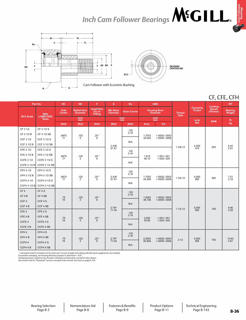
B-36
Ca
m F
oll
ow
er
Be
ari
ng
s
Inch Cam Follower Bearings
B-36
Part No. RD W SD SL C TL L R ECC G BDTrack Roller
Dynamic Rating
Track Roller Static Rating
Part No. HC HD F E Ro HBD
Thread Type
Clamping Torque
Limiting Speed
(Grease)
WT
W/O SealsWith
LUBRI-DISC Seals
Roller Diameter Roller Width Stud Diameter Stud Length
Endplate Extension
Min Thread Length
Length Overall
Crown Eccentric
W/O SealsWith
LUBRI-DISC Seals
Hole Center
Radial Hole Diameter
Axial Hole Dia or Fitting
Min Boss Diameter Outer Corner Housing Bore
DiameterBearing WeightPrefix
CCF-XXBase Modifier
CFE-XXinch mm
inch mm
inch mm
inch mm
inch mm
inch mm
inch mm lb/N
inch mm
inch mm
inch mm in-lb
Nm RPM lbkgNom. Tol. Nom. Tol. Nom. Tol. (Ref) (Ref) (Ref) (Ref) Radius
(Ref) (Ref) +0/-.010 ±.001 (Ref) (Ref) (Ref) (Ref) (Ref) Nom. Tol.
CF 3 1/2 CF 3 1/2 S
3.500 88.90
+0/-.001 +0/-.03
2.000 50.80
+0 / -.005 +0 / -.13
1.375 34.93
+.001/-0 +.03/-0
2.75 69.9
.031 .8
1.375 34.93
4.78 121.4
Cylindrical
N/A N/A N/A
22,800 101,414
31,625 140,668
CF 3 1/2 CF 3 1/2 S
.6875 17
.125 3
.25 * 6
2.438 61.91
.125 3.18
1.3753 34.933
+.0002/-.0003 +.0005/-.0008
1 3/8-12 4,200 475 820 6.42
2.91
CF 3 1/2 B CF 3 1/2 SB CF 3 1/2 B CF 3 1/2 SB
CCF 3 1/2 CCF 3 1/2 S 30 762
CCF 3 1/2 CCF 3 1/2 SN/A
CCF 3 1/2 B CCF 3 1/2 SB CCF 3 1/2 B CCF 3 1/2 SB
CFE 3 1/2 CFE 3 1/2 S
3.500 88.90
+0/-.001 +0/-.03
2.000 50.80
+0 / -.005 +0 / -.13
1.375 34.93
+.001/-0 +.03/-0
2.75 69.9
.031 .8
1.375 34.93
4.78 121.4
Cylindrical.060 .52
1.375 34.93
1.812 46.02
CFE 3 1/2 CFE 3 1/2 S
.6875 17
.125 3
.25 * 6
.125 3.18
1.815 46.10
+.001/-.001 +.025/-.025
CFE 3 1/2 B CFE 3 1/2 SB CFE 3 1/2 B CFE 3 1/2 SB
CCFE 3 1/2 CCFE 3 1/2 S 30 762
CCFE 3 1/2 CCFE 3 1/2 SN/A
CCFE 3 1/2 B CCFE 3 1/2 SB CCFE 3 1/2 B CCFE 3 1/2 SB
CFH 3 1/2 CFH 3 1/2 S
3.500 88.90
+0/-.001 +0/-.03
2.000 50.80
+0 / -.005 +0 / -.13
1.750 44.45
+.001/-0 +.03/-0
2.75 69.9
.031 .8
1.375 34.93
4.78 121.4
Cylindrical
N/A N/A N/A 22,800 101,414
63,250 281,336
CFH 3 1/2 CFH 3 1/2 S
.6875 17
.125 3
.25 * 6
2.438 61.91
.125 3.18
1.7503 44.458
+.0002/-.0003 +.0005/-.0008 1 3/4-12 5,000
565 820 7.01 3.18
CFH 3 1/2 B CFH 3 1/2 SB CFH 3 1/2 B CFH 3 1/2 SB
CCFH 3 1/2 CCFH 3 1/2 S 30 762
CCFH 3 1/2 CCFH 3 1/2 SN/A
CCFH 3 1/2 B CCFH 3 1/2 SB CCFH 3 1/2 B CCFH 3 1/2 SB
CF 4 CF 4 S
4.000 101.60
+0/-.001 +0/-.03
2.250 57.15
+0 / -.005 +0 / -.13
1.500 38.10
+.001/-0 +.03/-0
3.50 88.9
.031 .8
1.50 38.1
5.78 146.8
Cylindrical
N/A N/A N/A
22,800 101,414
44,770 199,137
CF 4 CF 4 S
.75 19
.125 3
.25 * 6
2.797 71.04
.125 3.18
1.5003 38.108
+.0002/-.0003 +.0005/-.0008
1 1/2-12 5,000 565 700 9.46
4.29
CF 4 B CF 4 SB CF 4 B CF 4 SB
CCF 4 CCF 4 S 30 762
CCF 4 CCF 4 SN/A
CCF 4 B CCF 4 SB CCF 4 B CCF 4 SB
CFE 4 CFE 4 S
4.000 101.60
+0/-.001 +0/-.03
2.250 57.15
+0 / -.005 +0 / -.13
1.500 38.10
+.001/-0 +.03/-0
3.50 88.9
.031 .8
1.50 38.1
5.78 146.8
Cylindrical.060 .52
2.000 50.80
2.000 50.80
CFE 4 CFE 4 S
.75 19
.125 3
.25 * 6
.125 3.18
2.002 50.85
+.001/-.001 +.025/-.025
CFE 4 B CFE 4 SB CFE 4 B CFE 4 SB
CCFE 4 CCFE 4 S 30 762
CCFE 4 CCFE 4 SN/A
CCFE 4 B CCFE 4 SB CCFE 4 B CCFE 4 SB
CFH 4 CFH 4 S
4.000 101.60
+0/-.001 +0/-.03
2.250 57.15
+0 / -.005 +0 / -.13
2.000 50.80
+.001/-0 +.03/-0
3.50 88.9
.031 .8
1.50 38.1
5.78 146.8
Cylindrical
N/A N/A N/A 29,985 133,373
89,540 398,274
CFH 4 CFH 4 S
.75 19
.125 3
.25 * 6
2.797 71.04
.125 3.18
2.0003 50.808
+.0002/-.0003 +.0005/-.0008 2-12 5,000
565 700 10.83 4.91
CFH 4 B CFH 4 SB CFH 4 B CFH 4 SB
CCFH 4 CCFH 4 S 30 762
CCFH 4 CCFH 4 SN/A
CCFH 4 B CCFH 4 SB CCFH 4 B CCFH 4 SB
CENTERLINEBEARING
ECC
F E
G
C
SL
TL
RD
W
BD
R
F SD
Ro
L
CF, CFE, CFH
Cam Follower with Eccentric Bushing
* Lubrication hole (F) at bottom of hex hole and 1/4 inch straight drive fitting will ball check supplied but not installed. For positive clamping, use housing thickness equal to G dimension =.010”. Clamping torque is based on dry threads. If threads are lubricated, use half of value shown. Hex wrench size for “Broached” version is located in the wrench size chart on page B-156.
Bearing SelectionPage B-3
Nomenclature AidPage B-8
Features & BenefitsPage B-9
Product OptionsPage B-11
Technical EngineeringPage B-143
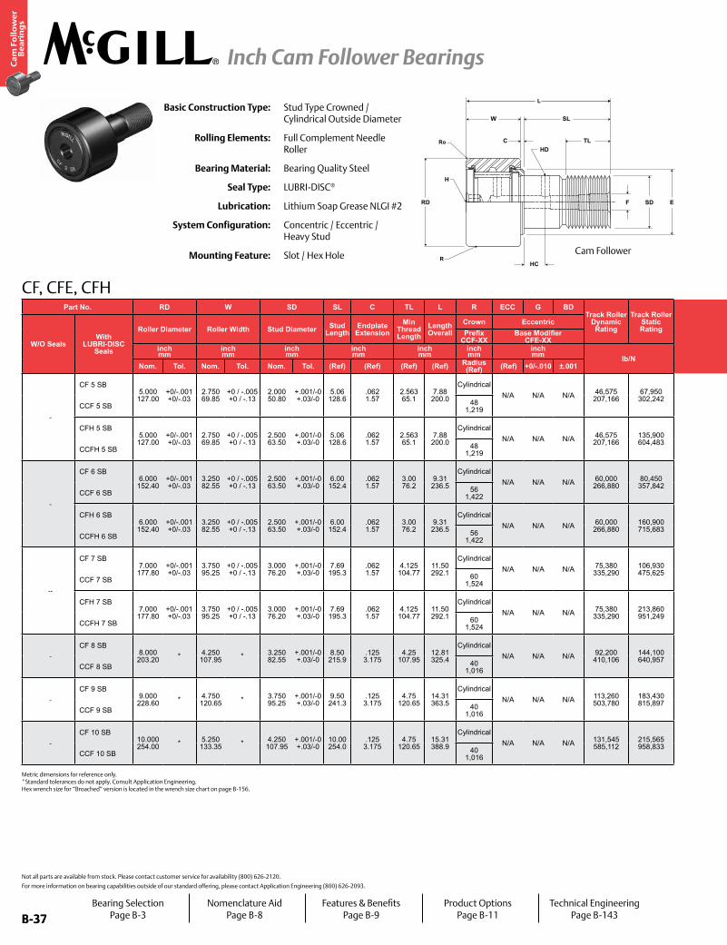
B-37
Ca
m F
oll
ow
er
Be
ari
ng
s
Inch Cam Follower Bearings
B-37
Part No. RD W SD SL C TL L R ECC G BDTrack Roller
Dynamic Rating
Track Roller Static Rating
Part No. HC HD F E Ro HBD
Thread Type
Clamping Torque
Limiting Speed
(Grease)
WT
W/O SealsWith
LUBRI-DISC Seals
Roller Diameter Roller Width Stud Diameter Stud Length
Endplate Extension
Min Thread Length
Length Overall
Crown Eccentric
W/O SealsWith
LUBRI-DISC Seals
Hole Center
Radial Hole Diameter
Axial Hole Dia or Fitting
Min Boss Diameter Outer Corner Housing Bore
DiameterBearing WeightPrefix
CCF-XXBase Modifier
CFE-XXinch mm
inch mm
inch mm
inch mm
inch mm
inch mm
inch mm lb/N
inch mm
inch mm
inch mm in-lb
Nm RPM lbkgNom. Tol. Nom. Tol. Nom. Tol. (Ref) (Ref) (Ref) (Ref) Radius
(Ref) (Ref) +0/-.010 ±.001 (Ref) (Ref) (Ref) (Ref) (Ref) Nom. Tol.
-
CF 5 SB5.000 127.00
+0/-.001 +0/-.03
2.750 69.85
+0 / -.005 +0 / -.13
2.000 50.80
+.001/-0 +.03/-0
5.06 128.6
.062 1.57
2.563 65.1
7.88 200.0
CylindricalN/A N/A N/A 46,575
207,16667,950
302,242
-
CF 5 S.875 22
.1875 5 1/4” NPT 3.563
90.49.125 3.18
2.0003 50.808
+.0002/-.0003 +.0005/-.0008 2-12 5,000
565 575 19.60 8.89
CCF 5 SB 48 1,219 CCF 5 S
CFH 5 SB5.000 127.00
+0/-.001 +0/-.03
2.750 69.85
+0 / -.005 +0 / -.13
2.500 63.50
+.001/-0 +.03/-0
5.06 128.6
.062 1.57
2.563 65.1
7.88 200.0
CylindricalN/A N/A N/A 46,575
207,166135,900 604,483
CFH 5 S.875 22
.1875 5 1/4” NPT 3.563
90.49.125 3.18
2.5030 63.576
+.0002/-.0003 +.0005/-.0008 2 1/2-12 5,000
565 575 22.10 10.02
CCFH 5 SB 48 1,219 CCFH 5 S
-
CF 6 SB6.000 152.40
+0/-.001 +0/-.03
3.250 82.55
+0 / -.005 +0 / -.13
2.500 63.50
+.001/-0 +.03/-0
6.00 152.4
.062 1.57
3.00 76.2
9.31 236.5
CylindricalN/A N/A N/A 60,000
266,88080,450
357,842
-
CF 6 S1.00 25
.1875 5 1/4” NPT 4.469
113.51.125 3.18
2.5030 63.576
+.0002/-.0003 +.0005/-.0008 2 1/2-12 5,000
565 475 32.73 14.85
CCF 6 SB 56 1,422 CCF 6 S
CFH 6 SB6.000 152.40
+0/-.001 +0/-.03
3.250 82.55
+0 / -.005 +0 / -.13
2.500 63.50
+.001/-0 +.03/-0
6.00 152.4
.062 1.57
3.00 76.2
9.31 236.5
CylindricalN/A N/A N/A 60,000
266,880160,900 715,683
CFH 6 S1.00 25
.1875 5 1/4” NPT 4.469
113.51.125 3.18
3.0003 76.208
+.0002/-.0003 +.0005/-.0008 3-12 5,000
565 475 36.41 16.52
CCFH 6 SB 56 1,422 CCFH 6 S
--
CF 7 SB7.000 177.80
+0/-.001 +0/-.03
3.750 95.25
+0 / -.005 +0 / -.13
3.000 76.20
+.001/-0 +.03/-0
7.69 195.3
.062 1.57
4.125 104.77
11.50 292.1
CylindricalN/A N/A N/A 75,380
335,290106,930 475,625
--
CF 7 S1.25 32
.1875 5 1/4” NPT 5.188
131.76.125 3.18
3.0003 76.208
+.0002/-.0003 +.0005/-.0008 3-12 5,000
565 400 54.73 24.83
CCF 7 SB 60 1,524 CCF 7 S
CFH 7 SB7.000 177.80
+0/-.001 +0/-.03
3.750 95.25
+0 / -.005 +0 / -.13
3.000 76.20
+.001/-0 +.03/-0
7.69 195.3
.062 1.57
4.125 104.77
11.50 292.1
CylindricalN/A N/A N/A 75,380
335,290213,860 951,249
CFH 7 S1.25 32
.1875 5 1/4” NPT 5.188
131.76.125 3.18
3.5003 88.908
+.0002/-.0003 +.0005/-.0008 3 1/2-4 5,000
565 400 68.03 30.86
CCFH 7 SB 60 1,524 CCFH 7 S
-
CF 8 SB8.000 203.20 * 4.250
107.95 * 3.250 82.55
+.001/-0 +.03/-0
8.50 215.9
.125 3.175
4.25 107.95
12.81 325.4
CylindricalN/A N/A N/A 92,200
410,106144,100 640,957 -
CF 8 S- - 1/4” NPT 4.375
111.13.219 5.56
3.2503 82.558
+.0002/-.0003 +.0005/-.0008 3 1/4-4 5,000
565 350 79.80 36.19
CCF 8 SB 40 1,016 CCF 8 S
-
CF 9 SB9.000 228.60 * 4.750
120.65 * 3.750 95.25
+.001/-0 +.03/-0
9.50 241.3
.125 3.175
4.75 120.65
14.31 363.5
CylindricalN/A N/A N/A 113,260
503,780183,430 815,897 -
CF 9 S- - 1/4” NPT 5.063
128.59.250 6.35
3.7503 95.258
+.0002/-.0003 +.0005/-.0008 3 1/2-4 5,000
565 300 111.60 50.62
CCF 9 SB 40 1,016 CCF 9 S
-
CF 10 SB10.000 254.00 * 5.250
133.35 * 4.250 107.95
+.001/-0 +.03/-0
10.00 254.0
.125 3.175
4.75 120.65
15.31 388.9
CylindricalN/A N/A N/A 131,545
585,112215,565 958,833 -
CF 10 S- - 1/4” NPT 5.469
138.91.281 7.14
4.2503 107.958
+.0002/-.0003 +.0005/-.0008 3 1/2-4 5,000
565 275 148.20 67.22
CCF 10 SB 40 1,016 CCF 10 S
HD
H
SDF
C
HC
RD
W SL
TL
E
R
Ro
L
CF, CFE, CFH
Basic Construction Type: Stud Type Crowned / Cylindrical Outside Diameter
Rolling Elements: Full Complement Needle Roller
Bearing Material: Bearing Quality Steel
Seal Type: LUBRI-DISC®
Lubrication: Lithium Soap Grease NLGI #2
System Configuration: Concentric / Eccentric / Heavy Stud
Mounting Feature: Slot / Hex Hole
Not all parts are available from stock. Please contact customer service for availability (800) 626-2120.
For more information on bearing capabilities outside of our standard offering, please contact Application Engineering (800) 626-2093.
Metric dimensions for reference only. *Standard tolerances do not apply. Consult Application Engineering. Hex wrench size for “Broached” version is located in the wrench size chart on page B-156.
Cam Follower
Bearing SelectionPage B-3
Nomenclature AidPage B-8
Features & BenefitsPage B-9
Product OptionsPage B-11
Technical EngineeringPage B-143
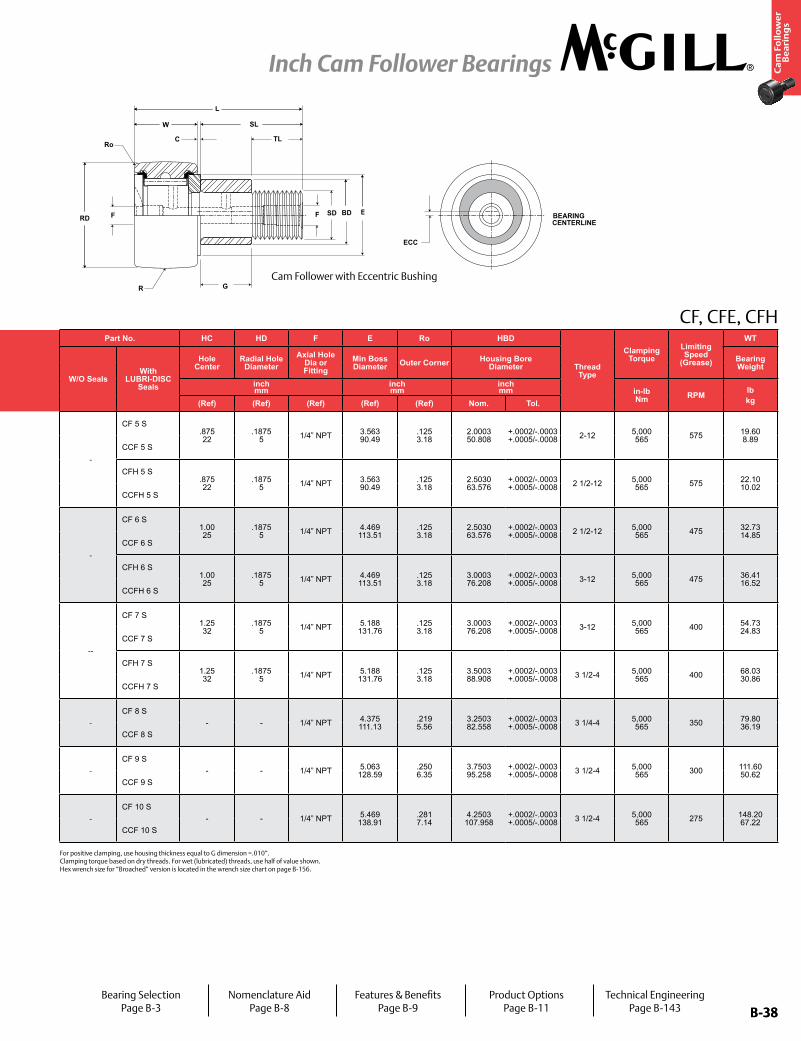
B-38
Ca
m F
oll
ow
er
Be
ari
ng
s
Inch Cam Follower Bearings
B-38
Part No. RD W SD SL C TL L R ECC G BDTrack Roller
Dynamic Rating
Track Roller Static Rating
Part No. HC HD F E Ro HBD
Thread Type
Clamping Torque
Limiting Speed
(Grease)
WT
W/O SealsWith
LUBRI-DISC Seals
Roller Diameter Roller Width Stud Diameter Stud Length
Endplate Extension
Min Thread Length
Length Overall
Crown Eccentric
W/O SealsWith
LUBRI-DISC Seals
Hole Center
Radial Hole Diameter
Axial Hole Dia or Fitting
Min Boss Diameter Outer Corner Housing Bore
DiameterBearing WeightPrefix
CCF-XXBase Modifier
CFE-XXinch mm
inch mm
inch mm
inch mm
inch mm
inch mm
inch mm lb/N
inch mm
inch mm
inch mm in-lb
Nm RPM lbkgNom. Tol. Nom. Tol. Nom. Tol. (Ref) (Ref) (Ref) (Ref) Radius
(Ref) (Ref) +0/-.010 ±.001 (Ref) (Ref) (Ref) (Ref) (Ref) Nom. Tol.
-
CF 5 SB5.000 127.00
+0/-.001 +0/-.03
2.750 69.85
+0 / -.005 +0 / -.13
2.000 50.80
+.001/-0 +.03/-0
5.06 128.6
.062 1.57
2.563 65.1
7.88 200.0
CylindricalN/A N/A N/A 46,575
207,16667,950 302,242
-
CF 5 S.875 22
.1875 5 1/4” NPT 3.563
90.49.125 3.18
2.0003 50.808
+.0002/-.0003 +.0005/-.0008 2-12 5,000
565 575 19.60 8.89
CCF 5 SB 48 1,219 CCF 5 S
CFH 5 SB5.000 127.00
+0/-.001 +0/-.03
2.750 69.85
+0 / -.005 +0 / -.13
2.500 63.50
+.001/-0 +.03/-0
5.06 128.6
.062 1.57
2.563 65.1
7.88 200.0
CylindricalN/A N/A N/A 46,575
207,166135,900 604,483
CFH 5 S.875 22
.1875 5 1/4” NPT 3.563
90.49.125 3.18
2.5030 63.576
+.0002/-.0003 +.0005/-.0008 2 1/2-12 5,000
565 575 22.10 10.02
CCFH 5 SB 48 1,219 CCFH 5 S
-
CF 6 SB6.000 152.40
+0/-.001 +0/-.03
3.250 82.55
+0 / -.005 +0 / -.13
2.500 63.50
+.001/-0 +.03/-0
6.00 152.4
.062 1.57
3.00 76.2
9.31 236.5
CylindricalN/A N/A N/A 60,000
266,88080,450 357,842
-
CF 6 S1.00 25
.1875 5 1/4” NPT 4.469
113.51.125 3.18
2.5030 63.576
+.0002/-.0003 +.0005/-.0008 2 1/2-12 5,000
565 475 32.73 14.85
CCF 6 SB 56 1,422 CCF 6 S
CFH 6 SB6.000 152.40
+0/-.001 +0/-.03
3.250 82.55
+0 / -.005 +0 / -.13
2.500 63.50
+.001/-0 +.03/-0
6.00 152.4
.062 1.57
3.00 76.2
9.31 236.5
CylindricalN/A N/A N/A 60,000
266,880160,900 715,683
CFH 6 S1.00 25
.1875 5 1/4” NPT 4.469
113.51.125 3.18
3.0003 76.208
+.0002/-.0003 +.0005/-.0008 3-12 5,000
565 475 36.41 16.52
CCFH 6 SB 56 1,422 CCFH 6 S
--
CF 7 SB7.000 177.80
+0/-.001 +0/-.03
3.750 95.25
+0 / -.005 +0 / -.13
3.000 76.20
+.001/-0 +.03/-0
7.69 195.3
.062 1.57
4.125 104.77
11.50 292.1
CylindricalN/A N/A N/A 75,380
335,290106,930 475,625
--
CF 7 S1.25 32
.1875 5 1/4” NPT 5.188
131.76.125 3.18
3.0003 76.208
+.0002/-.0003 +.0005/-.0008 3-12 5,000
565 400 54.73 24.83
CCF 7 SB 60 1,524 CCF 7 S
CFH 7 SB7.000 177.80
+0/-.001 +0/-.03
3.750 95.25
+0 / -.005 +0 / -.13
3.000 76.20
+.001/-0 +.03/-0
7.69 195.3
.062 1.57
4.125 104.77
11.50 292.1
CylindricalN/A N/A N/A 75,380
335,290213,860 951,249
CFH 7 S1.25 32
.1875 5 1/4” NPT 5.188
131.76.125 3.18
3.5003 88.908
+.0002/-.0003 +.0005/-.0008 3 1/2-4 5,000
565 400 68.03 30.86
CCFH 7 SB 60 1,524 CCFH 7 S
-
CF 8 SB8.000 203.20 * 4.250
107.95 * 3.250 82.55
+.001/-0 +.03/-0
8.50 215.9
.125 3.175
4.25 107.95
12.81 325.4
CylindricalN/A N/A N/A 92,200
410,106144,100 640,957 -
CF 8 S- - 1/4” NPT 4.375
111.13.219 5.56
3.2503 82.558
+.0002/-.0003 +.0005/-.0008 3 1/4-4 5,000
565 350 79.80 36.19
CCF 8 SB 40 1,016 CCF 8 S
-
CF 9 SB9.000 228.60 * 4.750
120.65 * 3.750 95.25
+.001/-0 +.03/-0
9.50 241.3
.125 3.175
4.75 120.65
14.31 363.5
CylindricalN/A N/A N/A 113,260
503,780183,430 815,897 -
CF 9 S- - 1/4” NPT 5.063
128.59.250 6.35
3.7503 95.258
+.0002/-.0003 +.0005/-.0008 3 1/2-4 5,000
565 300 111.60 50.62
CCF 9 SB 40 1,016 CCF 9 S
-
CF 10 SB10.000 254.00 * 5.250
133.35 * 4.250 107.95
+.001/-0 +.03/-0
10.00 254.0
.125 3.175
4.75 120.65
15.31 388.9
CylindricalN/A N/A N/A 131,545
585,112215,565 958,833 -
CF 10 S- - 1/4” NPT 5.469
138.91.281 7.14
4.2503 107.958
+.0002/-.0003 +.0005/-.0008 3 1/2-4 5,000
565 275 148.20 67.22
CCF 10 SB 40 1,016 CCF 10 S
CENTERLINEBEARING
ECC
F E
G
C
SL
TL
RD
W
BD
R
F SD
Ro
L
CF, CFE, CFH
For positive clamping, use housing thickness equal to G dimension =.010”. Clamping torque based on dry threads. For wet (lubricated) threads, use half of value shown. Hex wrench size for “Broached” version is located in the wrench size chart on page B-156.
Cam Follower with Eccentric Bushing
Bearing SelectionPage B-3
Nomenclature AidPage B-8
Features & BenefitsPage B-9
Product OptionsPage B-11
Technical EngineeringPage B-143
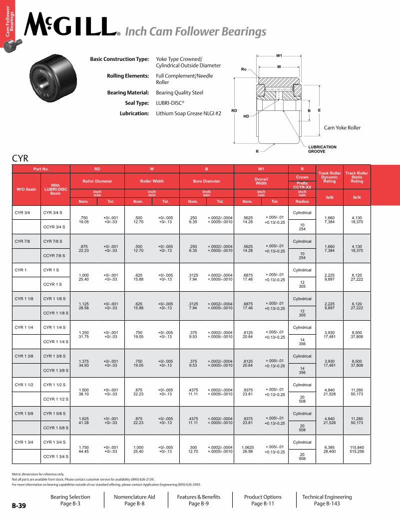
B-39
Ca
m F
oll
ow
er
Be
ari
ng
s
Inch Cam Follower Bearings
B-39
CYR
HD
LUBRICATIIONGROOVE
W1
W
B ERD
Ro
R
Basic Construction Type: Yoke Type Crowned/Cylindrical Outside Diameter
Rolling Elements: Full Complement/Needle Roller
Bearing Material: Bearing Quality Steel
Seal Type: LUBRI-DISC®
Lubrication: Lithium Soap Grease NLGI #2
Metric dimensions for reference only.
Not all parts are available from stock. Please contact customer service for availability (800) 626-2120.
For more information on bearing capabilities outside of our standard offering, please contact Application Engineering (800) 626-2093.
Part No. RD W B W1 RTrack Roller
Dynamic Rating
Track Roller Static Rating
Part No. HD E Ro Recommended Shaft Diameters Limiting
Speed
WT
W/O SealsWith
LUBRI-DISC Seals
Roller Diameter Roller Width Bore Diameter Overall Width
Crown
W/O SealsWith
LUBRI-DISC Seals
Hole Diameter
Min. Clamping Diameter
Outer Corner Bearing WeightPrefix
CCYR-XX Push Fit Drive Fit Press Fitinch mm
inch mm
inch mm
inch mm
inch mm lb/N lb/N
inch mm
inch mm
inch mm
inch mm RPM lb
kgNom. Tol. Nom. Tol. Nom. Tol. Nom. Tol. Radius (Ref) (Ref) (Ref) Nom Tol Nom Tol Nom Tol
CYR 3/4 CYR 3/4 S.750 19.05
+0/-.001 +0/-.03
.500 12.70
+0/-.005 +0/-.13
.250 6.35
+.0002/-.0004 +.0005/-.0010
.5625 14.28
+.005/-.01+0.13/-0.25
Cylindrical1,660 7,384
4,130 18,370
CYR 3/4 CYR 3/4 S.09 2.4
.61 15.5
.02 .4
.2495 6.337
±.0002 ±.005
.2501 6.353
±.0002 ±.005
.2503 6.357
±.0002 ±.005 6,400 .06
.03CCYR 3/4 S 10
254 CCYR 3/4 S N/A
CYR 7/8 CYR 7/8 S.875 22.23
+0/-.001 +0/-.03
.500 12.70
+0/-.005 +0/-.13
.250 6.35
+.0002/-.0004 +.0005/-.0010
.5625 14.28
+.005/-.01+0.13/-0.25
Cylindrical1,660 7,384
4,130 18,370
CYR 7/8 CYR 7/8 S.09 2.4
.61 15.5
.02 .4
.2495 6.337
±.0002 ±.005
.2501 6.353
±.0002 ±.005
.2503 6.357
±.0002 ±.005 5,400 .08
.04CCYR 7/8 S 10
254 CCYR 7/8 S N/A
CYR 1 CYR 1 S1.000 25.40
+0/-.001 +0/-.03
.625 15.88
+0/-.005 +0/-.13
.3125 7.94
+.0002/-.0004 +.0005/-.0010
.6875 17.46
+.005/-.01+0.13/-0.25
Cylindrical2,225 9,897
6,120 27,222
CYR 1 CYR 1 S.09 2.4
.78 19.8
.03 .8
.3120 7.925
±.0002 ±.005
.3126 7.940
±.0002 ±.005
.3128 7.945
±.0002 ±.005 4,800 .15
.07CCYR 1 S 12
305 CCYR 1 S N/A
CYR 1 1/8 CYR 1 1/8 S1.125 28.58
+0/-.001 +0/-.03
.625 15.88
+0/-.005 +0/-.13
.3125 7.94
+.0002/-.0004 +.0005/-.0010
.6875 17.46
+.005/-.01+0.13/-0.25
Cylindrical2,225 9,897
6,120 27,222
CYR 1 1/8 CYR 1 1/8 S.09 2.4
.78 19.8
.03 .8
.3120 7.925
±.0002 ±.005
.3126 7.940
±.0002 ±.005
.3128 7.945
±.0002 ±.005 3,400 .17
.08CCYR 1 1/8 S 12
305 CCYR 1 1/8 S N/A
CYR 1 1/4 CYR 1 1/4 S1.250 31.75
+0/-.001 +0/-.03
.750 19.05
+0/-.005 +0/-.13
.375 9.53
+.0002/-.0004 +.0005/-.0010
.8125 20.64
+.005/-.01+0.13/-0.25
Cylindrical3,930 17,481
8,500 37,808
CYR 1 1/4 CYR 1 1/4 S.09 2.4
.98 25.0
.03 .8
.3745 9.512
±.0002 ±.005
.3751 9.527
±.0002 ±.005
.3753 9.532
±.0002 ±.005 3,100 .24
.11CCYR 1 1/4 S 14
356 CCYR 1 1/4 S N/A
CYR 1 3/8 CYR 1 3/8 S1.375 34.93
+0/-.001 +0/-.03
.750 19.05
+0/-.005 +0/-.13
.375 9.53
+.0002/-.0004 +.0005/-.0010
.8125 20.64
+.005/-.01+0.13/-0.25
Cylindrical3,930 17,481
8,500 37,808
CYR 1 3/8 CYR 1 3/8 S.09 2.4
.98 25.0
.05 1.2
.3745 9.512
±.0002 ±.005
.3751 9.527
±.0002 ±.005
.3753 9.532
±.0002 ±.005 2,800 .30
.14CCYR 1 3/8 S 14
356 CCYR 1 3/8 S N/A
CYR 1 1/2 CYR 1 1/2 S1.500 38.10
+0/-.001 +0/-.03
.875 22.23
+0/-.005 +0/-.13
.4375 11.11
+.0002/-.0004 +.0005/-.0010
.9375 23.81
+.005/-.01+0.13/-0.25
Cylindrical4,840 21,528
11,280 50,173
CYR 1 1/2 CYR 1 1/2 S.09 2.4
1.09 27.8
.06 1.6
.4370 11.100
±.0002 ±.005
.4376 11.115
±.0002 ±.005
.4378 11.120
±.0002 ±.005 2,500 .41
.19CCYR 1 1/2 S 20
508 CCYR 1 1/2 S N/A
CYR 1 5/8 CYR 1 5/8 S1.625 41.28
+0/-.001 +0/-.03
.875 22.23
+0/-.005 +0/-.13
.4375 11.11
+.0002/-.0004 +.0005/-.0010
.9375 23.81
+.005/-.01+0.13/-0.25
Cylindrical4,840 21,528
11,280 50,173
CYR 1 5/8 CYR 1 5/8 S.09 2.4
1.09 27.8
.06 1.6
.4370 11.100
±.0002 ±.005
.4376 11.115
±.0002 ±.005
.4378 11.120
±.0002 ±.005 2,350 .50
.23CCYR 1 5/8 S 20
508 CCYR 1 5/8 S N/A
CYR 1 3/4 CYR 1 3/4 S1.750 44.45
+0/-.001 +0/-.03
1.000 25.40
+0/-.005 +0/-.13
.500 12.70
+.0002/-.0004 +.0005/-.0010
1.0625 26.98
+.005/-.01+0.13/-0.25
Cylindrical6,385 28,400
115,840 515,256
CYR 1 3/4 CYR 1 3/4 S.09 2.4
1.25 31.8
.06 1.6
.4995 12.687
±.0002 ±.005
.5001 12.703
±.0002 ±.005
.5005 12.713
±.0002 ±.005 2,200 .64
.29CCYR 1 3/4 S 20
508 CCYR 1 3/4 S N/A
Cam Yoke Roller
Bearing SelectionPage B-3
Nomenclature AidPage B-8
Features & BenefitsPage B-9
Product OptionsPage B-11
Technical EngineeringPage B-143
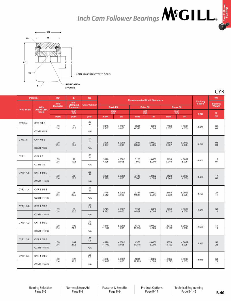
B-40
Ca
m F
oll
ow
er
Be
ari
ng
s
Inch Cam Follower Bearings
B-40
CYR
W
W1
RD B E
R
HD
LUBRICATION GROOVE
Ro
Part No. RD W B W1 RTrack Roller
Dynamic Rating
Track Roller Static Rating
Part No. HD E Ro Recommended Shaft Diameters Limiting
Speed
WT
W/O SealsWith
LUBRI-DISC Seals
Roller Diameter Roller Width Bore Diameter Overall Width
Crown
W/O SealsWith
LUBRI-DISC Seals
Hole Diameter
Min. Clamping Diameter
Outer Corner Bearing WeightPrefix
CCYR-XX Push Fit Drive Fit Press Fitinch mm
inch mm
inch mm
inch mm
inch mm lb/N lb/N
inch mm
inch mm
inch mm
inch mm RPM lb
kgNom. Tol. Nom. Tol. Nom. Tol. Nom. Tol. Radius (Ref) (Ref) (Ref) Nom Tol Nom Tol Nom Tol
CYR 3/4 CYR 3/4 S.750 19.05
+0/-.001 +0/-.03
.500 12.70
+0/-.005 +0/-.13
.250 6.35
+.0002/-.0004 +.0005/-.0010
.5625 14.28
+.005/-.01+0.13/-0.25
Cylindrical1,660 7,384
4,130 18,370
CYR 3/4 CYR 3/4 S.09 2.4
.61 15.5
.02 .4
.2495 6.337
±.0002 ±.005
.2501 6.353
±.0002 ±.005
.2503 6.357
±.0002 ±.005 6,400 .06
.03CCYR 3/4 S 10
254 CCYR 3/4 S N/A
CYR 7/8 CYR 7/8 S.875 22.23
+0/-.001 +0/-.03
.500 12.70
+0/-.005 +0/-.13
.250 6.35
+.0002/-.0004 +.0005/-.0010
.5625 14.28
+.005/-.01+0.13/-0.25
Cylindrical1,660 7,384
4,130 18,370
CYR 7/8 CYR 7/8 S.09 2.4
.61 15.5
.02 .4
.2495 6.337
±.0002 ±.005
.2501 6.353
±.0002 ±.005
.2503 6.357
±.0002 ±.005 5,400 .08
.04CCYR 7/8 S 10
254 CCYR 7/8 S N/A
CYR 1 CYR 1 S1.000 25.40
+0/-.001 +0/-.03
.625 15.88
+0/-.005 +0/-.13
.3125 7.94
+.0002/-.0004 +.0005/-.0010
.6875 17.46
+.005/-.01+0.13/-0.25
Cylindrical2,225 9,897
6,120 27,222
CYR 1 CYR 1 S.09 2.4
.78 19.8
.03 .8
.3120 7.925
±.0002 ±.005
.3126 7.940
±.0002 ±.005
.3128 7.945
±.0002 ±.005 4,800 .15
.07CCYR 1 S 12
305 CCYR 1 S N/A
CYR 1 1/8 CYR 1 1/8 S1.125 28.58
+0/-.001 +0/-.03
.625 15.88
+0/-.005 +0/-.13
.3125 7.94
+.0002/-.0004 +.0005/-.0010
.6875 17.46
+.005/-.01+0.13/-0.25
Cylindrical2,225 9,897
6,120 27,222
CYR 1 1/8 CYR 1 1/8 S.09 2.4
.78 19.8
.03 .8
.3120 7.925
±.0002 ±.005
.3126 7.940
±.0002 ±.005
.3128 7.945
±.0002 ±.005 3,400 .17
.08CCYR 1 1/8 S 12
305 CCYR 1 1/8 S N/A
CYR 1 1/4 CYR 1 1/4 S1.250 31.75
+0/-.001 +0/-.03
.750 19.05
+0/-.005 +0/-.13
.375 9.53
+.0002/-.0004 +.0005/-.0010
.8125 20.64
+.005/-.01+0.13/-0.25
Cylindrical3,930 17,481
8,500 37,808
CYR 1 1/4 CYR 1 1/4 S.09 2.4
.98 25.0
.03 .8
.3745 9.512
±.0002 ±.005
.3751 9.527
±.0002 ±.005
.3753 9.532
±.0002 ±.005 3,100 .24
.11CCYR 1 1/4 S 14
356 CCYR 1 1/4 S N/A
CYR 1 3/8 CYR 1 3/8 S1.375 34.93
+0/-.001 +0/-.03
.750 19.05
+0/-.005 +0/-.13
.375 9.53
+.0002/-.0004 +.0005/-.0010
.8125 20.64
+.005/-.01+0.13/-0.25
Cylindrical3,930 17,481
8,500 37,808
CYR 1 3/8 CYR 1 3/8 S.09 2.4
.98 25.0
.05 1.2
.3745 9.512
±.0002 ±.005
.3751 9.527
±.0002 ±.005
.3753 9.532
±.0002 ±.005 2,800 .30
.14CCYR 1 3/8 S 14
356 CCYR 1 3/8 S N/A
CYR 1 1/2 CYR 1 1/2 S1.500 38.10
+0/-.001 +0/-.03
.875 22.23
+0/-.005 +0/-.13
.4375 11.11
+.0002/-.0004 +.0005/-.0010
.9375 23.81
+.005/-.01+0.13/-0.25
Cylindrical4,840 21,528
11,280 50,173
CYR 1 1/2 CYR 1 1/2 S.09 2.4
1.09 27.8
.06 1.6
.4370 11.100
±.0002 ±.005
.4376 11.115
±.0002 ±.005
.4378 11.120
±.0002 ±.005 2,500 .41
.19CCYR 1 1/2 S 20
508 CCYR 1 1/2 S N/A
CYR 1 5/8 CYR 1 5/8 S1.625 41.28
+0/-.001 +0/-.03
.875 22.23
+0/-.005 +0/-.13
.4375 11.11
+.0002/-.0004 +.0005/-.0010
.9375 23.81
+.005/-.01+0.13/-0.25
Cylindrical4,840 21,528
11,280 50,173
CYR 1 5/8 CYR 1 5/8 S.09 2.4
1.09 27.8
.06 1.6
.4370 11.100
±.0002 ±.005
.4376 11.115
±.0002 ±.005
.4378 11.120
±.0002 ±.005 2,350 .50
.23CCYR 1 5/8 S 20
508 CCYR 1 5/8 S N/A
CYR 1 3/4 CYR 1 3/4 S1.750 44.45
+0/-.001 +0/-.03
1.000 25.40
+0/-.005 +0/-.13
.500 12.70
+.0002/-.0004 +.0005/-.0010
1.0625 26.98
+.005/-.01+0.13/-0.25
Cylindrical6,385 28,400
115,840 515,256
CYR 1 3/4 CYR 1 3/4 S.09 2.4
1.25 31.8
.06 1.6
.4995 12.687
±.0002 ±.005
.5001 12.703
±.0002 ±.005
.5005 12.713
±.0002 ±.005 2,200 .64
.29CCYR 1 3/4 S 20
508 CCYR 1 3/4 S N/A
Cam Yoke Roller with Seals
Bearing SelectionPage B-3
Nomenclature AidPage B-8
Features & BenefitsPage B-9
Product OptionsPage B-11
Technical EngineeringPage B-143
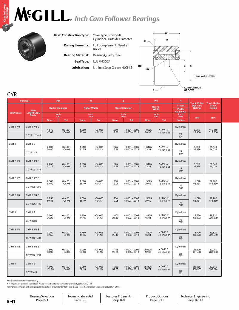
B-41
Ca
m F
oll
ow
er
Be
ari
ng
s
Inch Cam Follower Bearings
B-41
CYR
HD
LUBRICATIIONGROOVE
W1
W
B ERD
Ro
R
Metric dimensions for reference only.
Not all parts are available from stock. Please contact customer service for availability (800) 626-2120.
For more information on bearing capabilities outside of our standard offering, please contact Application Engineering (800) 626-2093.
Basic Construction Type: Yoke Type Crowned/Cylindrical Outside Diameter
Rolling Elements: Full Complement/Needle Roller
Bearing Material: Bearing Quality Steel
Seal Type: LUBRI-DISC®
Lubrication: Lithium Soap Grease NLGI #2
Part No. RD W B W1 RTrack Roller
Dynamic Rating
Track Roller Static Rating
Part No. HD E Ro Recommended Shaft Diameters Limiting
Speed
WT
W/O SealsWith
LUBRI-DISC Seals
Roller Diameter Roller Width Bore Diameter Overall Width
Crown
W/O SealsWith
LUBRI-DISC Seals
Hole Diameter
Min. Clamping Diameter
Outer Corner Bearing WeightPrefix
CCYR-XX Push Fit Drive Fit Press Fitinch mm
inch mm
inch mm
inch mm
inch mm lb/N lb/N
inch mm
inch mm
inch mm
inch mm RPM lb
kgNom. Tol. Nom. Tol. Nom. Tol. Nom. Tol. Radius (Ref) (Ref) (Ref) Nom Tol Nom Tol Nom Tol
CYR 1 7/8 CYR 1 7/8 S1.875 47.63
+0/-.001 +0/-.03
1.000 25.40
+0/-.005 +0/-.13
.500 12.70
+.0001/-.0005 +.0003/-.0013
1.0625 26.98
+.005/-.01+0.13/-0.25
Cylindrical6,385 28,400
115,840 515,256
CYR 1 7/8 CYR 1 7/8 S.09 2.4
1.25 31.8
.06 1.6
.4995 12.687
±.0002 ±.005
.5001 12.703
±.0002 ±.005
.5005 12.713
±.0002 ±.005 2,000 .80
.36CCYR 1 7/8 S 20
508 CCYR 1 7/8 S N/A
CYR 2 CYR 2 S2.000 50.80
+0/-.001 +0/-.03
1.250 31.75
+0/-.005 +0/-.13
.625 15.88
+.0001/-.0005 +.0003/-.0013
1.3125 33.34
+.005/-.01+0.13/-0.25
Cylindrical8,090 35,984
21,140 94,031
CYR 2 CYR 2 S.13 3.2
1.41 35.7
.09 2.4
.6245 15.862
±.0002 ±.005
.6245 15.862
±.0002 ±.005
.6245 15.862
±.0002 ±.005 1,400 1.05
.48CCYR 2 S 24
610 CCYR 2 S N/A
CYR 2 1/4 CYR 2 1/4 S2.250 57.15
+0/-.001 +0/-.03
1.250 31.75
+0/-.005 +0/-.13
.625 15.88
+.0001/-.0005 +.0003/-.0013
1.3125 33.34
+.005/-.01+0.13/-0.25
Cylindrical8,090 35,984
21,140 94,031
CYR 2 1/4 CYR 2 1/4 S.13 3.2
1.41 35.7
.09 2.4
.6245 15.862
±.0002 ±.005
.6251 15.877
±.0002 ±.005
.6255 15.887
±.0002 ±.005 1,300 1.32
.59CCYR 2 1/4 S 24
610 CCYR 2 1/4 S N/A
CYR 2 1/2 CYR 2 1/2 S2.500 63.50
+0/-.001 +0/-.03
1.500 38.10
+0/-.005 +0/-.13
.750 19.05
+.0001/-.0005 +.0003/-.0013
1.5625 39.69
+.005/-.01+0.13/-0.25
Cylindrical11,720 52,131
32,900 146,339
CYR 2 1/2 CYR 2 1/2 S.13 3.2
1.69 42.9
.09 2.4
.7495 19.037
±.0002 ±.005
.7501 19.053
±.0002 ±.005
.75015 19.063
±.0002 ±.005 1,100 1.80
.82CCYR 2 1/2 S 30
762 CCYR 2 1/2 S N/A
CYR 2 3/4 CYR 2 3/4 S2.750 69.85
+0/-.001 +0/-.03
1.500 38.10
+0/-.005 +0/-.13
.750 19.05
+.0001/-.0005 +.0003/-.0013
1.5625 39.69
+.005/-.01+0.13/-0.25
Cylindrical11,720 52,131
32,900 146,339
CYR 2 3/4 CYR 2 3/4 S.13 3.2
1.69 42.9
.09 2.4
.7495 19.037
±.0002 ±.005
.7501 19.053
±.0002 ±.005
.75015 19.063
±.0002 ±.005 1,050 2.25
1.02CCYR 2 3/4 S 30
762 CCYR 2 3/4 S N/A
CYR 3 CYR 3 S3.000 76.20
+0/-.001 +0/-.03
1.750 44.45
+0/-.005 +0/-.13
1.000 25.40
+.0001/-.0005 +.0003/-.0013
1.8125 46.04
+.005/-.01+0.13/-0.25
Cylindrical15,720 69,923
49,820 221,599
CYR 3 CYR 3 S.13 3.2
2.13 54.0
.13 3.2
.9994 25.385
+.0002/-.0003 +.005/-.008
1.0002 25.405
+.0002/-.0003 +.005/-.008
1.0006 25.415
+.0002/-.0003 +.005/-.008 950 3.10
1.41CCYR 3 S 30
762 CCYR 3 S N/A
CYR 3 1/4 CYR 3 1/4 S3.250 82.55
+0/-.001 +0/-.03
1.750 44.45
+0/-.005 +0/-.13
1.000 25.40
+.0001/-.0005 +.0003/-.0013
1.8125 46.04
+.005/-.01+0.13/-0.25
Cylindrical15,720 69,923
49,820 221,599
CYR 3 1/4 CYR 3 1/4 S.13 3.2
2.13 54.0
.13 3.2
.9994 25.385
+.0002/-.0003 +.005/-.008
1.0002 25.405
+.0002/-.0003 +.005/-.008
1.0006 25.415
+.0002/-.0003 +.005/-.008 880 3.62
1.64CCYR 3 1/4 S 30
762 CCYR 3 1/4 S N/A
CYR 3 1/2 CYR 3 1/2 S3.500 88.90
+0/-.001 +0/-.03
2.000 50.80
+0/-.005 +0/-.13
1.125 28.58
+.0001/-.0005 +.0003/-.0013
2.0625 52.39
+.005/-.01+0.13/-0.25
Cylindrical22,800 101,414
63,250 281,336
CYR 3 1/2 CYR 3 1/2 S.13 3.2
2.44 61.9
.13 3.2
1.1244 28.560
+.0002/-.0003 +.005/-.008
1.1252 28.580
+.0002/-.0003 +.005/-.008
1.1256 28.590
+.0002/-.0003 +.005/-.008 820 4.95
2.25CCYR 3 1/2 S 30
762 CCYR 3 1/2 S N/A
CYR 4 CYR 4 S4.000 101.60
+0/-.001 +0/-.03
2.250 57.15
+0/-.005 +0/-.13
1.250 31.75
+.0001/-.0005 +.0003/-.0013
2.3125 58.74
+.005/-.01+0.13/-0.25
Cylindrical29,985 133,373
89,540 398,274
CYR 4 CYR 4 S.13 3.2
2.80 71.0
.13 3.2
1.2494 31.735
+.0002/-.0003 +.005/-.008
1.2502 31.755
+.0002/-.0003 +.005/-.008
1.2506 31.765
+.0002/-.0003 +.005/-.008 700 7.05
3.19CCYR 4 S 30
762 CCYR 4 S N/A
Cam Yoke Roller
Bearing SelectionPage B-3
Nomenclature AidPage B-8
Features & BenefitsPage B-9
Product OptionsPage B-11
Technical EngineeringPage B-143
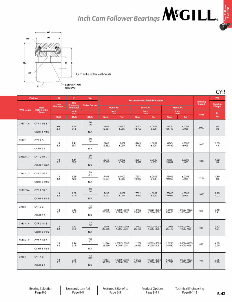
B-42
Ca
m F
oll
ow
er
Be
ari
ng
s
Inch Cam Follower Bearings
B-42
CYR
W
W1
RD B E
R
HD
LUBRICATION GROOVE
Ro
Part No. RD W B W1 RTrack Roller
Dynamic Rating
Track Roller Static Rating
Part No. HD E Ro Recommended Shaft Diameters Limiting
Speed
WT
W/O SealsWith
LUBRI-DISC Seals
Roller Diameter Roller Width Bore Diameter Overall Width
Crown
W/O SealsWith
LUBRI-DISC Seals
Hole Diameter
Min. Clamping Diameter
Outer Corner Bearing WeightPrefix
CCYR-XX Push Fit Drive Fit Press Fitinch mm
inch mm
inch mm
inch mm
inch mm lb/N lb/N
inch mm
inch mm
inch mm
inch mm RPM lb
kgNom. Tol. Nom. Tol. Nom. Tol. Nom. Tol. Radius (Ref) (Ref) (Ref) Nom Tol Nom Tol Nom Tol
CYR 1 7/8 CYR 1 7/8 S1.875 47.63
+0/-.001 +0/-.03
1.000 25.40
+0/-.005 +0/-.13
.500 12.70
+.0001/-.0005 +.0003/-.0013
1.0625 26.98
+.005/-.01+0.13/-0.25
Cylindrical6,385 28,400
115,840 515,256
CYR 1 7/8 CYR 1 7/8 S.09 2.4
1.25 31.8
.06 1.6
.4995 12.687
±.0002 ±.005
.5001 12.703
±.0002 ±.005
.5005 12.713
±.0002 ±.005 2,000 .80
.36CCYR 1 7/8 S 20
508 CCYR 1 7/8 S N/A
CYR 2 CYR 2 S2.000 50.80
+0/-.001 +0/-.03
1.250 31.75
+0/-.005 +0/-.13
.625 15.88
+.0001/-.0005 +.0003/-.0013
1.3125 33.34
+.005/-.01+0.13/-0.25
Cylindrical8,090 35,984
21,140 94,031
CYR 2 CYR 2 S.13 3.2
1.41 35.7
.09 2.4
.6245 15.862
±.0002 ±.005
.6245 15.862
±.0002 ±.005
.6245 15.862
±.0002 ±.005 1,400 1.05
.48CCYR 2 S 24
610 CCYR 2 S N/A
CYR 2 1/4 CYR 2 1/4 S2.250 57.15
+0/-.001 +0/-.03
1.250 31.75
+0/-.005 +0/-.13
.625 15.88
+.0001/-.0005 +.0003/-.0013
1.3125 33.34
+.005/-.01+0.13/-0.25
Cylindrical8,090 35,984
21,140 94,031
CYR 2 1/4 CYR 2 1/4 S.13 3.2
1.41 35.7
.09 2.4
.6245 15.862
±.0002 ±.005
.6251 15.877
±.0002 ±.005
.6255 15.887
±.0002 ±.005 1,300 1.32
.59CCYR 2 1/4 S 24
610 CCYR 2 1/4 S N/A
CYR 2 1/2 CYR 2 1/2 S2.500 63.50
+0/-.001 +0/-.03
1.500 38.10
+0/-.005 +0/-.13
.750 19.05
+.0001/-.0005 +.0003/-.0013
1.5625 39.69
+.005/-.01+0.13/-0.25
Cylindrical11,720 52,131
32,900 146,339
CYR 2 1/2 CYR 2 1/2 S.13 3.2
1.69 42.9
.09 2.4
.7495 19.037
±.0002 ±.005
.7501 19.053
±.0002 ±.005
.75015 19.063
±.0002 ±.005 1,100 1.80
.82CCYR 2 1/2 S 30
762 CCYR 2 1/2 S N/A
CYR 2 3/4 CYR 2 3/4 S2.750 69.85
+0/-.001 +0/-.03
1.500 38.10
+0/-.005 +0/-.13
.750 19.05
+.0001/-.0005 +.0003/-.0013
1.5625 39.69
+.005/-.01+0.13/-0.25
Cylindrical11,720 52,131
32,900 146,339
CYR 2 3/4 CYR 2 3/4 S.13 3.2
1.69 42.9
.09 2.4
.7495 19.037
±.0002 ±.005
.7501 19.053
±.0002 ±.005
.75015 19.063
±.0002 ±.005 1,050 2.25
1.02CCYR 2 3/4 S 30
762 CCYR 2 3/4 S N/A
CYR 3 CYR 3 S3.000 76.20
+0/-.001 +0/-.03
1.750 44.45
+0/-.005 +0/-.13
1.000 25.40
+.0001/-.0005 +.0003/-.0013
1.8125 46.04
+.005/-.01+0.13/-0.25
Cylindrical15,720 69,923
49,820 221,599
CYR 3 CYR 3 S.13 3.2
2.13 54.0
.13 3.2
.9994 25.385
+.0002/-.0003 +.005/-.008
1.0002 25.405
+.0002/-.0003 +.005/-.008
1.0006 25.415
+.0002/-.0003 +.005/-.008 950 3.10
1.41CCYR 3 S 30
762 CCYR 3 S N/A
CYR 3 1/4 CYR 3 1/4 S3.250 82.55
+0/-.001 +0/-.03
1.750 44.45
+0/-.005 +0/-.13
1.000 25.40
+.0001/-.0005 +.0003/-.0013
1.8125 46.04
+.005/-.01+0.13/-0.25
Cylindrical15,720 69,923
49,820 221,599
CYR 3 1/4 CYR 3 1/4 S.13 3.2
2.13 54.0
.13 3.2
.9994 25.385
+.0002/-.0003 +.005/-.008
1.0002 25.405
+.0002/-.0003 +.005/-.008
1.0006 25.415
+.0002/-.0003 +.005/-.008 880 3.62
1.64CCYR 3 1/4 S 30
762 CCYR 3 1/4 S N/A
CYR 3 1/2 CYR 3 1/2 S3.500 88.90
+0/-.001 +0/-.03
2.000 50.80
+0/-.005 +0/-.13
1.125 28.58
+.0001/-.0005 +.0003/-.0013
2.0625 52.39
+.005/-.01+0.13/-0.25
Cylindrical22,800 101,414
63,250 281,336
CYR 3 1/2 CYR 3 1/2 S.13 3.2
2.44 61.9
.13 3.2
1.1244 28.560
+.0002/-.0003 +.005/-.008
1.1252 28.580
+.0002/-.0003 +.005/-.008
1.1256 28.590
+.0002/-.0003 +.005/-.008 820 4.95
2.25CCYR 3 1/2 S 30
762 CCYR 3 1/2 S N/A
CYR 4 CYR 4 S4.000 101.60
+0/-.001 +0/-.03
2.250 57.15
+0/-.005 +0/-.13
1.250 31.75
+.0001/-.0005 +.0003/-.0013
2.3125 58.74
+.005/-.01+0.13/-0.25
Cylindrical29,985 133,373
89,540 398,274
CYR 4 CYR 4 S.13 3.2
2.80 71.0
.13 3.2
1.2494 31.735
+.0002/-.0003 +.005/-.008
1.2502 31.755
+.0002/-.0003 +.005/-.008
1.2506 31.765
+.0002/-.0003 +.005/-.008 700 7.05
3.19CCYR 4 S 30
762 CCYR 4 S N/A
Cam Yoke Roller with Seals
Bearing SelectionPage B-3
Nomenclature AidPage B-8
Features & BenefitsPage B-9
Product OptionsPage B-11
Technical EngineeringPage B-143
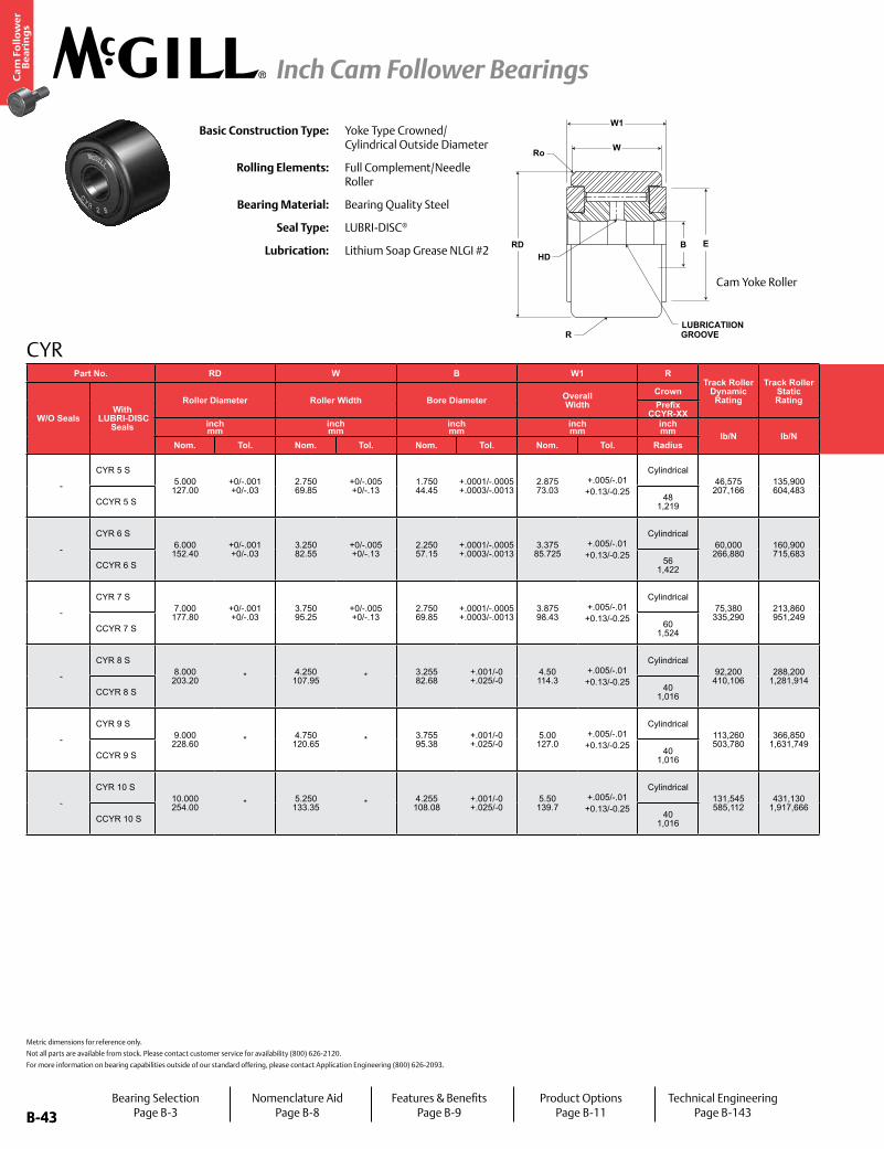
B-43
Ca
m F
oll
ow
er
Be
ari
ng
s
Inch Cam Follower Bearings
B-43
Part No. RD W B W1 RTrack Roller
Dynamic Rating
Track Roller Static Rating
Part No. HD E Ro Recommended Shaft Diameters Limiting
Speed
WT
W/O SealsWith
LUBRI-DISC Seals
Roller Diameter Roller Width Bore Diameter Overall Width
Crown
W/O SealsWith
LUBRI-DISC Seals
Hole Diameter
Min. Clamping Diameter
Outer Corner Bearing WeightPrefix
CCYR-XX Push Fit Drive Fit Press Fitinch mm
inch mm
inch mm
inch mm
inch mm lb/N lb/N
inch mm
inch mm
inch mm
inch mm RPM lb
kgNom. Tol. Nom. Tol. Nom. Tol. Nom. Tol. Radius (Ref) (Ref) (Ref) Nom Tol Nom Tol Nom Tol
-
CYR 5 S5.000 127.00
+0/-.001 +0/-.03
2.750 69.85
+0/-.005 +0/-.13
1.750 44.45
+.0001/-.0005 +.0003/-.0013
2.875 73.03
+.005/-.01+0.13/-0.25
Cylindrical46,575 207,166
135,900 604,483 -
CYR 5 S.19 4.8
3.56 90.5
.13 3.2
1.7494 44.435
+.0002/-.0003 +.005/-.008
1.7502 44.455
+.0002/-.0003 +.005/-.008
1.7506 44.465
+.0002/-.0003 +.005/-.008 575 14.34
6.59CCYR 5 S 48
1,219 CCYR 5 S N/A
-
CYR 6 S6.000 152.40
+0/-.001 +0/-.03
3.250 82.55
+0/-.005 +0/-.13
2.250 57.15
+.0001/-.0005 +.0003/-.0013
3.375 85.725
+.005/-.01+0.13/-0.25
Cylindrical60,000 266,880
160,900 715,683 -
CYR 6 S.19 4.8
4.47 113.5
.13 3.2
2.2494 57.135
+.0002/-.0003 +.005/-.008
2.2502 57.155
+.0002/-.0003 +.005/-.008
2.2506 57.165
+.0002/-.0003 +.005/-.008 475 20.16
9.14CCYR 6 S 56
1,422 CCYR 6 S N/A
-
CYR 7 S7.000 177.80
+0/-.001 +0/-.03
3.750 95.25
+0/-.005 +0/-.13
2.750 69.85
+.0001/-.0005 +.0003/-.0013
3.875 98.43
+.005/-.01+0.13/-0.25
Cylindrical75,380 335,290
213,860 951,249 -
CYR 7 S.19 4.8
5.19 131.8
.13 3.2
2.7494 69.835
+.0002/-.0003 +.005/-.008
2.7502 69.855
+.0002/-.0003 +.005/-.008
2.7506 69.865
+.0002/-.0003 +.005/-.008 400 32.43
14.71CCYR 7 S 60
1,524 CCYR 7 S N/A
-
CYR 8 S8.000 203.20 * 4.250
107.95 * 3.255 82.68
+.001/-0 +.025/-0
4.50 114.3
+.005/-.01+0.13/-0.25
Cylindrical92,200 410,106
288,200 1,281,914 -
CYR 8 S.25 6.4
4.38 111.1
.22 5.6
3.2545 82.664
±.0005 ±.0013
3.2560 82.702
±.0005 ±.0013
3.2565 82.715
±.0005 ±.0013 350 47.30
21.45CCYR 8 S 40
1,016 CCYR 8 S N/A
-
CYR 9 S9.000 228.60 * 4.750
120.65 * 3.755 95.38
+.001/-0 +.025/-0
5.00 127.0
+.005/-.01+0.13/-0.25
Cylindrical113,260 503,780
366,850 1,631,749 -
CYR 9 S.31 7.9
5.06 128.6
.25 6.4
3.7545 95.364
±.0005 ±.0013
3.7560 95.402
±.0005 ±.0013
3.7565 95.415
±.0005 ±.0013 300 65.70
29.80CCYR 9 S 40
1,016 CCYR 9 S N/A
-
CYR 10 S10.000 254.00 * 5.250
133.35 * 4.255 108.08
+.001/-0 +.025/-0
5.50 139.7
+.005/-.01+0.13/-0.25
Cylindrical131,545 585,112
431,130 1,917,666 -
CYR 10 S.38 9.5
5.47 138.9
.28 7.1
4.2545 108.064
±.0005 ±.0013
4.2560 108.102
±.0005 ±.0013
4.2565 108.115
±.0005 ±.0013 275 89.20
40.46CCYR 10 S 40
1,016 CCYR 10 S N/A
CYR
HD
LUBRICATIIONGROOVE
W1
W
B ERD
Ro
R
Metric dimensions for reference only.
Not all parts are available from stock. Please contact customer service for availability (800) 626-2120.
For more information on bearing capabilities outside of our standard offering, please contact Application Engineering (800) 626-2093.
Basic Construction Type: Yoke Type Crowned/Cylindrical Outside Diameter
Rolling Elements: Full Complement/Needle Roller
Bearing Material: Bearing Quality Steel
Seal Type: LUBRI-DISC®
Lubrication: Lithium Soap Grease NLGI #2
Cam Yoke Roller
Bearing SelectionPage B-3
Nomenclature AidPage B-8
Features & BenefitsPage B-9
Product OptionsPage B-11
Technical EngineeringPage B-143
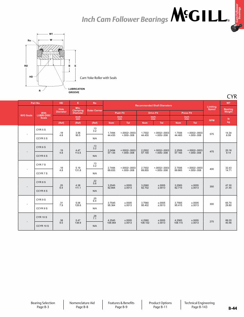
B-44
Ca
m F
oll
ow
er
Be
ari
ng
s
Inch Cam Follower Bearings
B-44
Part No. RD W B W1 RTrack Roller
Dynamic Rating
Track Roller Static Rating
Part No. HD E Ro Recommended Shaft Diameters Limiting
Speed
WT
W/O SealsWith
LUBRI-DISC Seals
Roller Diameter Roller Width Bore Diameter Overall Width
Crown
W/O SealsWith
LUBRI-DISC Seals
Hole Diameter
Min. Clamping Diameter
Outer Corner Bearing WeightPrefix
CCYR-XX Push Fit Drive Fit Press Fitinch mm
inch mm
inch mm
inch mm
inch mm lb/N lb/N
inch mm
inch mm
inch mm
inch mm RPM lb
kgNom. Tol. Nom. Tol. Nom. Tol. Nom. Tol. Radius (Ref) (Ref) (Ref) Nom Tol Nom Tol Nom Tol
-
CYR 5 S5.000 127.00
+0/-.001 +0/-.03
2.750 69.85
+0/-.005 +0/-.13
1.750 44.45
+.0001/-.0005 +.0003/-.0013
2.875 73.03
+.005/-.01+0.13/-0.25
Cylindrical46,575 207,166
135,900 604,483 -
CYR 5 S.19 4.8
3.56 90.5
.13 3.2
1.7494 44.435
+.0002/-.0003 +.005/-.008
1.7502 44.455
+.0002/-.0003 +.005/-.008
1.7506 44.465
+.0002/-.0003 +.005/-.008 575 14.34
6.59CCYR 5 S 48
1,219 CCYR 5 S N/A
-
CYR 6 S6.000 152.40
+0/-.001 +0/-.03
3.250 82.55
+0/-.005 +0/-.13
2.250 57.15
+.0001/-.0005 +.0003/-.0013
3.375 85.725
+.005/-.01+0.13/-0.25
Cylindrical60,000 266,880
160,900 715,683 -
CYR 6 S.19 4.8
4.47 113.5
.13 3.2
2.2494 57.135
+.0002/-.0003 +.005/-.008
2.2502 57.155
+.0002/-.0003 +.005/-.008
2.2506 57.165
+.0002/-.0003 +.005/-.008 475 20.16
9.14CCYR 6 S 56
1,422 CCYR 6 S N/A
-
CYR 7 S7.000 177.80
+0/-.001 +0/-.03
3.750 95.25
+0/-.005 +0/-.13
2.750 69.85
+.0001/-.0005 +.0003/-.0013
3.875 98.43
+.005/-.01+0.13/-0.25
Cylindrical75,380 335,290
213,860 951,249 -
CYR 7 S.19 4.8
5.19 131.8
.13 3.2
2.7494 69.835
+.0002/-.0003 +.005/-.008
2.7502 69.855
+.0002/-.0003 +.005/-.008
2.7506 69.865
+.0002/-.0003 +.005/-.008 400 32.43
14.71CCYR 7 S 60
1,524 CCYR 7 S N/A
-
CYR 8 S8.000 203.20 * 4.250
107.95 * 3.255 82.68
+.001/-0 +.025/-0
4.50 114.3
+.005/-.01+0.13/-0.25
Cylindrical92,200 410,106
288,200 1,281,914 -
CYR 8 S.25 6.4
4.38 111.1
.22 5.6
3.2545 82.664
±.0005 ±.0013
3.2560 82.702
±.0005 ±.0013
3.2565 82.715
±.0005 ±.0013 350 47.30
21.45CCYR 8 S 40
1,016 CCYR 8 S N/A
-
CYR 9 S9.000 228.60 * 4.750
120.65 * 3.755 95.38
+.001/-0 +.025/-0
5.00 127.0
+.005/-.01+0.13/-0.25
Cylindrical113,260 503,780
366,850 1,631,749 -
CYR 9 S.31 7.9
5.06 128.6
.25 6.4
3.7545 95.364
±.0005 ±.0013
3.7560 95.402
±.0005 ±.0013
3.7565 95.415
±.0005 ±.0013 300 65.70
29.80CCYR 9 S 40
1,016 CCYR 9 S N/A
-
CYR 10 S10.000 254.00 * 5.250
133.35 * 4.255 108.08
+.001/-0 +.025/-0
5.50 139.7
+.005/-.01+0.13/-0.25
Cylindrical131,545 585,112
431,130 1,917,666 -
CYR 10 S.38 9.5
5.47 138.9
.28 7.1
4.2545 108.064
±.0005 ±.0013
4.2560 108.102
±.0005 ±.0013
4.2565 108.115
±.0005 ±.0013 275 89.20
40.46CCYR 10 S 40
1,016 CCYR 10 S N/A
CYR
W
W1
RD B E
R
HD
LUBRICATION GROOVE
Ro
Cam Yoke Roller with Seals
Bearing SelectionPage B-3
Nomenclature AidPage B-8
Features & BenefitsPage B-9
Product OptionsPage B-11
Technical EngineeringPage B-143
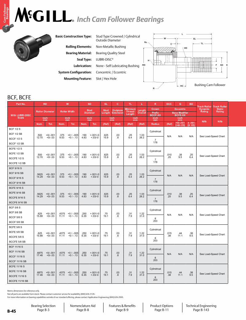
B-45
Ca
m F
oll
ow
er
Be
ari
ng
s
Inch Cam Follower Bearings
B-45
BCF, BCFE
Basic Construction Type: Stud Type Crowned / Cylindrical Outside Diameter
Rolling Elements: Non-Metallic Bushing
Bearing Material: Bearing Quality Steel
Seal Type: LUBRI-DISC®
Lubrication: None - Self Lubricating Bushing
System Configuration: Concentric / Eccentric
Mounting Feature: Slot / Hex Hole
Metric dimensions for reference only.
Not all parts are available from stock. Please contact customer service for availability (800) 626-2120.
For more information on bearing capabilities outside of our standard offering, please contact Application Engineering (800) 626-2093.
RD
W
C
SL
TL
HD
H
HC
F SD E
R
Ro
L
Part No. RD W SD SL C TL L R ECC G BDTrack Roller
Dynamic Rating
Track Roller Static Rating
Part No. HC HD F H E Ro
Housing Bore Diameter Thread
Type
Clamping Torque
Limiting Speed
WT
With LUBRI-DISC Seals
Roller Diameter Roller Width Stud Diameter
Stud Length
Endplate Extension
Minimum Thread Length
Length Overall
Crown Eccentric
With LUBRI-DISC Seals
Hole Center
Radial Hole Diameter
Axial Hole Dia
or FittingHex Hole Min Boss
DiameterOuter
Corner Radius
Bearing WeightPrefix
BCCF-XX Base Modifier
BCFE-XXinch mm
inch mm
inch mm
inch mm
inch mm
inch mm
inch mm N/lb N/lb
inch mm
inch mm
inch mm
inch mm in-lb
Nm RPM lbkgNom. Tol. Nom. Tol. Nom. Tol. (Ref) (Ref) (Ref) (Ref) Radius (Ref) +0/-.001
(+0/-.03)± .001 (± .03) (Ref) (Ref) (Ref) (Ref) (Ref) (Ref) Nom. Tol.
BCF 1/2 S
.500 12.70
+0/-.001 +0/-.03
.375 9.53
+0 / -.005 +0 / -.13
.190 4.83
+.001/-0 +.03/-0
.625 15.9
.03 .8
.25 6.4
1.03 26.2
Cylindrical
N/A N/A N/A See Load-Speed Chart
BCF 1/2 S
- - .125 3.17
.125 3.17
.41 10.4
.02 .4
.1903 4.834
+.0002/-.0003 +.0005/-.0008 10-32 15
2See Load-
Speed Chart.04 .02
BCF 1/2 SB BCF 1/2 SB
BCCF 1/2 S 7 178
BCCF 1/2 SN/A
BCCF 1/2 SB BCCF 1/2 SB
BCFE 1/2 S
.500 12.70
+0/-.001 +0/-.03
.375 9.53
+0 / -.005 +0 / -.13
.190 4.83
+.001/-0 +.03/-0
.625 15.9
.03 .8
.25 6.4
1.03 26.2
Cylindrical.010 .25
.38 9.5
.25 6.4 See Load-Speed Chart
BCFE 1/2 S
- - .125 3.17
.125 3.17
.41 10.4
.02 .4
.253 6.426
+.001/-.001 +.025/-.025 10-32 15
2See Load-
Speed Chart.04 .02
BCFE 1/2 SB BCFE 1/2 SB
BCCFE 1/2 S 7 178
BCCFE 1/2 SN/A
BCCFE 1/2 SB BCCFE 1/2 SB
BCF 9/16 S
.5625 14.29
+0/-.001 +0/-.03
.375 9.53
+0 / -.005 +0 / -.13
.190 4.83
+.001/-0 +.03/-0
.625 15.9
.03 .8
.25 6.4
1.03 26.2
Cylindrical
N/A N/A N/A See Load-Speed Chart
BCF 9/16 S
- - .125 3.17
.125 3.17
.41 10.4
.02 .4
.1903 4.834
+.0002/-.0003 +.0005/-.0008 10-32 15
2See Load-
Speed Chart.04 .02
BCF 9/16 SB BCF 9/16 SB
BCCF 9/16 S 7 178
BCCF 9/16 SN/A
BCCF 9/16 SB BCCF 9/16 SB
BCFE 9/16 S
.5625 14.29
+0/-.001 +0/-.03
.375 9.53
+0 / -.005 +0 / -.13
.190 4.83
+.001/-0 +.03/-0
.625 15.9
.03 .8
.25 6.4
1.03 26.2
Cylindrical.010 .25
.38 9.5
.25 6.4 See Load-Speed Chart
BCFE 9/16 S
- - .125 3.17
.125 3.17
.41 10.4
.02 .4
.253 6.426
+.001/-.001 +.025/-.025 10-32 15
2See Load-
Speed Chart.04 .02
BCFE 9/16 SB BCFE 9/16 SB
BCCFE 9/16 S 7 178
BCCFE 9/16 SN/A
BCCFE 9/16 SB BCCFE 9/16 SB
BCF 5/8 S
.625 15.88
+0/-.001 +0/-.03
.4375 11.11
+0 / -.005 +0 / -.13
.250 6.35
+.001/-0 +.03/-0
.75 19.1
.03 .8
.31 7.9
1.22 31.0
Cylindrical
N/A N/A N/A See Load-Speed Chart
BCF 5/8 S
- - .125 3.17
.125 3.17
.46 11.7
.02 .4
.2503 6.358
+.0002/-.0003 +.0005/-.0008 1/4-28 35
4See Load-
Speed Chart.05 .02
BCF 5/8 SB BCF 5/8 SB
BCCF 5/8 S 8 203
BCCF 5/8 SN/A
BCCF 5/8 SB BCCF 5/8 SB
BCFE 5/8 S
.625 15.88
+0/-.001 +0/-.03
.4375 11.11
+0 / -.005 +0 / -.13
.250 6.35
+.001/-0 +.03/-0
.75 19.1
.03 .8
.31 7.9
1.22 31.0
Cylindrical.015 .38
.44 11.1
.38 9.5 See Load-Speed Chart
BCFE 5/8 S
- - .125 3.17
.125 3.17
.46 11.7
.02 .4
.378 9.60
+.001/-.001 +.025/-.025 1/4-28 35
4See Load-
Speed Chart.05 .02
BCFE 5/8 SB BCFE 5/8 SB
BCCFE 5/8 S 8 203
BCCFE 5/8 SN/A
BCCFE 5/8 SB BCCFE 5/8 SB
BCF 11/16 S
.6875 17.46
+0/-.001 +0/-.03
.4375 11.11
+0 / -.005 +0 / -.13
.250 6.35
+.001/-0 +.03/-0
.75 19.1
.03 .8
.31 7.9
1.22 31.0
Cylindrical
N/A N/A N/A See Load-Speed Chart
BCF 11/16 S
- - .125 3.17
.125 3.17
.46 11.7
.02 .4
.2503 6.358
+.0002/-.0003 +.0005/-.0008 1/4-28 35
4See Load-
Speed Chart.06 .03
BCF 11/16 SB BCF 11/16 SB
BCCF 11/16 S 8 203
BCCF 11/16 SN/A
BCCF 11/16 SB BCCF 11/16 SB
BCFE 11/16 S
.6875 17.46
+0/-.001 +0/-.03
.4375 11.11
+0 / -.005 +0 / -.13
.250 6.35
+.001/-0 +.03/-0
.75 19.1
.03 .8
.31 7.9
1.22 31.0
Cylindrical.015 .38
.44 11.1
.38 9.5 See Load-Speed Chart
BCFE 11/16 S
- - .125 3.17
.125 3.17
.46 11.7
.02 .4
.378 9.60
+.001/-.001 +.025/-.025 1/4-28 35
4See Load-
Speed Chart.06 .03
BCFE 11/16 SB BCFE 11/16 SB
BCCFE 11/16 S 8 203
BCCFE 11/16 SN/A
BCCFE 11/16 SB BCCFE 11/16 SB
Bushing Cam Follower
Bearing SelectionPage B-3
Nomenclature AidPage B-8
Features & BenefitsPage B-9
Product OptionsPage B-11
Technical EngineeringPage B-143
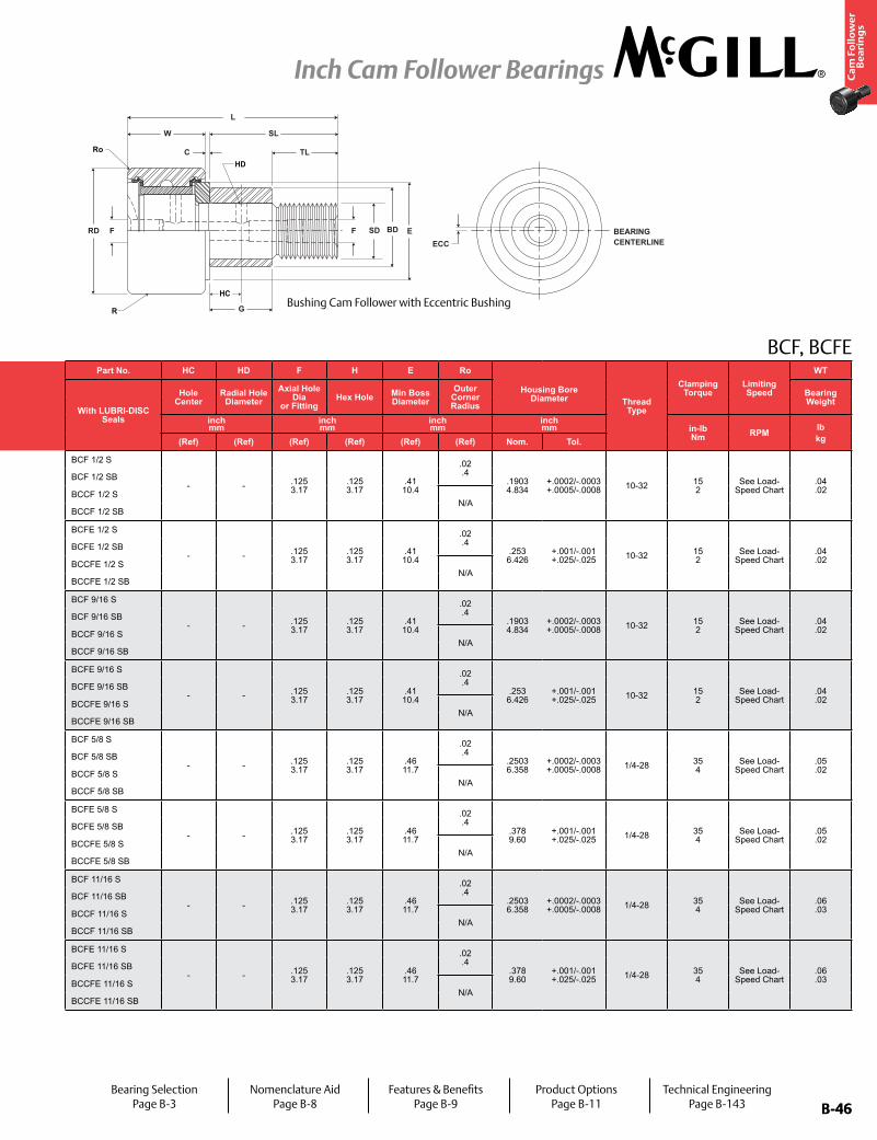
B-46
Ca
m F
oll
ow
er
Be
ari
ng
s
Inch Cam Follower Bearings
B-46
BCF, BCFE
FRD
C
W SL
TL
F BD E
G
BEARINGCENTERLINEECC
L
SD
R
Ro
HD
HC
Part No. RD W SD SL C TL L R ECC G BDTrack Roller
Dynamic Rating
Track Roller Static Rating
Part No. HC HD F H E Ro
Housing Bore Diameter Thread
Type
Clamping Torque
Limiting Speed
WT
With LUBRI-DISC Seals
Roller Diameter Roller Width Stud Diameter
Stud Length
Endplate Extension
Minimum Thread Length
Length Overall
Crown Eccentric
With LUBRI-DISC Seals
Hole Center
Radial Hole Diameter
Axial Hole Dia
or FittingHex Hole Min Boss
DiameterOuter
Corner Radius
Bearing WeightPrefix
BCCF-XX Base Modifier
BCFE-XXinch mm
inch mm
inch mm
inch mm
inch mm
inch mm
inch mm N/lb N/lb
inch mm
inch mm
inch mm
inch mm in-lb
Nm RPM lbkgNom. Tol. Nom. Tol. Nom. Tol. (Ref) (Ref) (Ref) (Ref) Radius (Ref) +0/-.001
(+0/-.03)± .001 (± .03) (Ref) (Ref) (Ref) (Ref) (Ref) (Ref) Nom. Tol.
BCF 1/2 S
.500 12.70
+0/-.001 +0/-.03
.375 9.53
+0 / -.005 +0 / -.13
.190 4.83
+.001/-0 +.03/-0
.625 15.9
.03 .8
.25 6.4
1.03 26.2
Cylindrical
N/A N/A N/A See Load-Speed Chart
BCF 1/2 S
- - .125 3.17
.125 3.17
.41 10.4
.02 .4
.1903 4.834
+.0002/-.0003 +.0005/-.0008 10-32 15
2See Load-
Speed Chart.04 .02
BCF 1/2 SB BCF 1/2 SB
BCCF 1/2 S 7 178
BCCF 1/2 SN/A
BCCF 1/2 SB BCCF 1/2 SB
BCFE 1/2 S
.500 12.70
+0/-.001 +0/-.03
.375 9.53
+0 / -.005 +0 / -.13
.190 4.83
+.001/-0 +.03/-0
.625 15.9
.03 .8
.25 6.4
1.03 26.2
Cylindrical.010 .25
.38 9.5
.25 6.4 See Load-Speed Chart
BCFE 1/2 S
- - .125 3.17
.125 3.17
.41 10.4
.02 .4
.253 6.426
+.001/-.001 +.025/-.025 10-32 15
2See Load-
Speed Chart.04 .02
BCFE 1/2 SB BCFE 1/2 SB
BCCFE 1/2 S 7 178
BCCFE 1/2 SN/A
BCCFE 1/2 SB BCCFE 1/2 SB
BCF 9/16 S
.5625 14.29
+0/-.001 +0/-.03
.375 9.53
+0 / -.005 +0 / -.13
.190 4.83
+.001/-0 +.03/-0
.625 15.9
.03 .8
.25 6.4
1.03 26.2
Cylindrical
N/A N/A N/A See Load-Speed Chart
BCF 9/16 S
- - .125 3.17
.125 3.17
.41 10.4
.02 .4
.1903 4.834
+.0002/-.0003 +.0005/-.0008 10-32 15
2See Load-
Speed Chart.04 .02
BCF 9/16 SB BCF 9/16 SB
BCCF 9/16 S 7 178
BCCF 9/16 SN/A
BCCF 9/16 SB BCCF 9/16 SB
BCFE 9/16 S
.5625 14.29
+0/-.001 +0/-.03
.375 9.53
+0 / -.005 +0 / -.13
.190 4.83
+.001/-0 +.03/-0
.625 15.9
.03 .8
.25 6.4
1.03 26.2
Cylindrical.010 .25
.38 9.5
.25 6.4 See Load-Speed Chart
BCFE 9/16 S
- - .125 3.17
.125 3.17
.41 10.4
.02 .4
.253 6.426
+.001/-.001 +.025/-.025 10-32 15
2See Load-
Speed Chart.04 .02
BCFE 9/16 SB BCFE 9/16 SB
BCCFE 9/16 S 7 178
BCCFE 9/16 SN/A
BCCFE 9/16 SB BCCFE 9/16 SB
BCF 5/8 S
.625 15.88
+0/-.001 +0/-.03
.4375 11.11
+0 / -.005 +0 / -.13
.250 6.35
+.001/-0 +.03/-0
.75 19.1
.03 .8
.31 7.9
1.22 31.0
Cylindrical
N/A N/A N/A See Load-Speed Chart
BCF 5/8 S
- - .125 3.17
.125 3.17
.46 11.7
.02 .4
.2503 6.358
+.0002/-.0003 +.0005/-.0008 1/4-28 35
4See Load-
Speed Chart.05 .02
BCF 5/8 SB BCF 5/8 SB
BCCF 5/8 S 8 203
BCCF 5/8 SN/A
BCCF 5/8 SB BCCF 5/8 SB
BCFE 5/8 S
.625 15.88
+0/-.001 +0/-.03
.4375 11.11
+0 / -.005 +0 / -.13
.250 6.35
+.001/-0 +.03/-0
.75 19.1
.03 .8
.31 7.9
1.22 31.0
Cylindrical.015 .38
.44 11.1
.38 9.5 See Load-Speed Chart
BCFE 5/8 S
- - .125 3.17
.125 3.17
.46 11.7
.02 .4
.378 9.60
+.001/-.001 +.025/-.025 1/4-28 35
4See Load-
Speed Chart.05 .02
BCFE 5/8 SB BCFE 5/8 SB
BCCFE 5/8 S 8 203
BCCFE 5/8 SN/A
BCCFE 5/8 SB BCCFE 5/8 SB
BCF 11/16 S
.6875 17.46
+0/-.001 +0/-.03
.4375 11.11
+0 / -.005 +0 / -.13
.250 6.35
+.001/-0 +.03/-0
.75 19.1
.03 .8
.31 7.9
1.22 31.0
Cylindrical
N/A N/A N/A See Load-Speed Chart
BCF 11/16 S
- - .125 3.17
.125 3.17
.46 11.7
.02 .4
.2503 6.358
+.0002/-.0003 +.0005/-.0008 1/4-28 35
4See Load-
Speed Chart.06 .03
BCF 11/16 SB BCF 11/16 SB
BCCF 11/16 S 8 203
BCCF 11/16 SN/A
BCCF 11/16 SB BCCF 11/16 SB
BCFE 11/16 S
.6875 17.46
+0/-.001 +0/-.03
.4375 11.11
+0 / -.005 +0 / -.13
.250 6.35
+.001/-0 +.03/-0
.75 19.1
.03 .8
.31 7.9
1.22 31.0
Cylindrical.015 .38
.44 11.1
.38 9.5 See Load-Speed Chart
BCFE 11/16 S
- - .125 3.17
.125 3.17
.46 11.7
.02 .4
.378 9.60
+.001/-.001 +.025/-.025 1/4-28 35
4See Load-
Speed Chart.06 .03
BCFE 11/16 SB BCFE 11/16 SB
BCCFE 11/16 S 8 203
BCCFE 11/16 SN/A
BCCFE 11/16 SB BCCFE 11/16 SB
Bushing Cam Follower with Eccentric Bushing
Bearing SelectionPage B-3
Nomenclature AidPage B-8
Features & BenefitsPage B-9
Product OptionsPage B-11
Technical EngineeringPage B-143
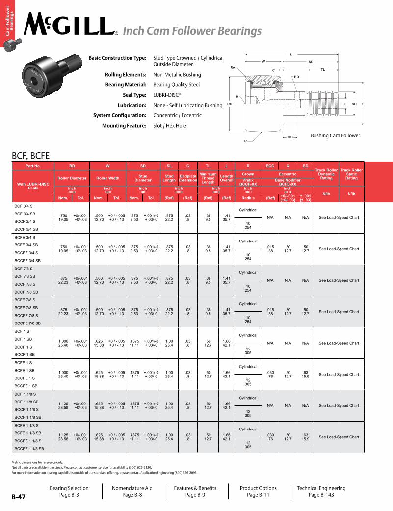
B-47
Ca
m F
oll
ow
er
Be
ari
ng
s
Inch Cam Follower Bearings
B-47
Part No. RD W SD SL C TL L R ECC G BDTrack Roller
Dynamic Rating
Track Roller Static Rating
Part No. HC HD F H E Ro
Housing Bore Diameter Thread
Type
Clamping Torque
Limiting Speed
WT
With LUBRI-DISC Seals
Roller Diameter Roller Width Stud Diameter
Stud Length
Endplate Extension
Minimum Thread Length
Length Overall
Crown Eccentric
With LUBRI-DISC Seals
Hole Center
Radial Hole Diameter
Axial Hole Dia
or FittingHex Hole Min Boss
DiameterOuter
Corner Radius
Bearing WeightPrefix
BCCF-XX Base Modifier
BCFE-XXinch mm
inch mm
inch mm
inch mm
inch mm
inch mm
inch mm N/lb N/lb
inch mm
inch mm
inch mm
inch mm in-lb
Nm RPM lbkgNom. Tol. Nom. Tol. Nom. Tol. (Ref) (Ref) (Ref) (Ref) Radius (Ref) +0/-.001
(+0/-.03)± .001 (± .03) (Ref) (Ref) (Ref) (Ref) (Ref) (Ref) Nom. Tol.
BCF 3/4 S
.750 19.05
+0/-.001 +0/-.03
.500 12.70
+0 / -.005 +0 / -.13
.375 9.53
+.001/-0 +.03/-0
.875 22.2
.03 .8
.38 9.5
1.41 35.7
Cylindrical
N/A N/A N/A See Load-Speed Chart
BCF 3/4 S
.25 6.4
.09 2.4
.1875 4.76
.1875 4.76
.61 15.5
.02 .4
.3753 9.533
+.0002/-.0003 +.0005/-.0008 3/8-24 95
11See Load-
Speed Chart.07 .03
BCF 3/4 SB BCF 3/4 SB
BCCF 3/4 S 10 254
BCCF 3/4 SN/A
BCCF 3/4 SB BCCF 3/4 SB
BCFE 3/4 S
.750 19.05
+0/-.001 +0/-.03
.500 12.70
+0 / -.005 +0 / -.13
.375 9.53
+.001/-0 +.03/-0
.875 22.2
.03 .8
.38 9.5
1.41 35.7
Cylindrical.015 .38
.50 12.7
.50 12.7 See Load-Speed Chart
BCFE 3/4 S
.25 6.4
.09 2.4
.1875 4.76
.1875 4.76
.61 15.5
.02 .4
.503 12.77
+.001/-.001 +.025/-.025 3/8-24 95
11See Load-
Speed Chart.07 .03
BCFE 3/4 SB BCFE 3/4 SB
BCCFE 3/4 S 10 254
BCCFE 3/4 SN/A
BCCFE 3/4 SB BCCFE 3/4 SB
BCF 7/8 S
.875 22.23
+0/-.001 +0/-.03
.500 12.70
+0 / -.005 +0 / -.13
.375 9.53
+.001/-0 +.03/-0
.875 22.2
.03 .8
.38 9.5
1.41 35.7
Cylindrical
N/A N/A N/A See Load-Speed Chart
BCF 7/8 S
.25 6.4
.09 2.4
.1875 4.76
.1875 4.76
.61 15.5
.02 .4
.3753 9.533
+.0002/-.0003 +.0005/-.0008 3/8-24 95
11See Load-
Speed Chart.09 .04
BCF 7/8 SB BCF 7/8 SB
BCCF 7/8 S 10 254
BCCF 7/8 SN/A
BCCF 7/8 SB BCCF 7/8 SB
BCFE 7/8 S
.875 22.23
+0/-.001 +0/-.03
.500 12.70
+0 / -.005 +0 / -.13
.375 9.53
+.001/-0 +.03/-0
.875 22.2
.03 .8
.38 9.5
1.41 35.7
Cylindrical.015 .38
.50 12.7
.50 12.7 See Load-Speed Chart
BCFE 7/8 S
.25 6.4
.09 2.4
.1875 4.76
.1875 4.76
.61 15.5
.02 .4
.503 12.77
+.001/-.001 +.025/-.025 3/8-24 95
11See Load-
Speed Chart.09 .04
BCFE 7/8 SB BCFE 7/8 SB
BCCFE 7/8 S 10 254
BCCFE 7/8 SN/A
BCCFE 7/8 SB BCCFE 7/8 SB
BCF 1 S
1.000 25.40
+0/-.001 +0/-.03
.625 15.88
+0 / -.005 +0 / -.13
.4375 11.11
+.001/-0 +.03/-0
1.00 25.4
.03 .8
.50 12.7
1.66 42.1
Cylindrical
N/A N/A N/A See Load-Speed Chart
BCF 1 S
.25 6.4
.09 2.4
.1875 4.76
.25 6.4
.78 19.8
.03 .8
.4378 11.120
+.0002/-.0003 +.0005/-.0008 7/16-20 250
28See Load-
Speed Chart.17 .08
BCF 1 SB BCF 1 SB
BCCF 1 S 12 305
BCCF 1 SN/A
BCCF 1 SB BCCF 1 SB
BCFE 1 S
1.000 25.40
+0/-.001 +0/-.03
.625 15.88
+0 / -.005 +0 / -.13
.4375 11.11
+.001/-0 +.03/-0
1.00 25.4
.03 .8
.50 12.7
1.66 42.1
Cylindrical.030 .76
.50 12.7
.63 15.9 See Load-Speed Chart
BCFE 1 S
.25 6.4
.09 2.4
.1875 4.76
.25 6.4
.78 19.8
.03 .8
.628 15.95
+.001/-.001 +.025/-.025 7/16-20 250
28See Load-
Speed Chart.17 .08
BCFE 1 SB BCFE 1 SB
BCCFE 1 S 12 305
BCCFE 1 SN/A
BCCFE 1 SB BCCFE 1 SB
BCF 1 1/8 S
1.125 28.58
+0/-.001 +0/-.03
.625 15.88
+0 / -.005 +0 / -.13
.4375 11.11
+.001/-0 +.03/-0
1.00 25.4
.03 .8
.50 12.7
1.66 42.1
Cylindrical
N/A N/A N/A See Load-Speed Chart
BCF 1 1/8 S
.25 6.4
.09 2.4
.1875 4.76
.25 6.4
.78 19.8
.03 .8
.4378 11.120
+.0002/-.0003 +.0005/-.0008 7/16-20 250
28See Load-
Speed Chart.19 .09
BCF 1 1/8 SB BCF 1 1/8 SB
BCCF 1 1/8 S 12 305
BCCF 1 1/8 SN/A
BCCF 1 1/8 SB BCCF 1 1/8 SB
BCFE 1 1/8 S
1.125 28.58
+0/-.001 +0/-.03
.625 15.88
+0 / -.005 +0 / -.13
.4375 11.11
+.001/-0 +.03/-0
1.00 25.4
.03 .8
.50 12.7
1.66 42.1
Cylindrical.030 .76
.50 12.7
.63 15.9 See Load-Speed Chart
BCFE 1 1/8 S
.25 6.4
.09 2.4
.1875 4.76
.25 6.4
.78 19.8
.03 .8
.628 15.95
+.001/-.001 +.025/-.025 7/16-20 250
28See Load-
Speed Chart.19 .09
BCFE 1 1/8 SB BCFE 1 1/8 SB
BCCFE 1 1/8 S 12 305
BCCFE 1 1/8 SN/A
BCCFE 1 1/8 SB BCCFE 1 1/8 SB
BCF, BCFE
Metric dimensions for reference only.
Not all parts are available from stock. Please contact customer service for availability (800) 626-2120.
For more information on bearing capabilities outside of our standard offering, please contact Application Engineering (800) 626-2093.
Basic Construction Type: Stud Type Crowned / Cylindrical Outside Diameter
Rolling Elements: Non-Metallic Bushing
Bearing Material: Bearing Quality Steel
Seal Type: LUBRI-DISC®
Lubrication: None - Self Lubricating Bushing
System Configuration: Concentric / Eccentric
Mounting Feature: Slot / Hex Hole
RD
W
C
SL
TL
HD
H
HC
F SD E
R
Ro
L
Bushing Cam Follower
Bearing SelectionPage B-3
Nomenclature AidPage B-8
Features & BenefitsPage B-9
Product OptionsPage B-11
Technical EngineeringPage B-143

B-48
Ca
m F
oll
ow
er
Be
ari
ng
s
Inch Cam Follower Bearings
B-48
Part No. RD W SD SL C TL L R ECC G BDTrack Roller
Dynamic Rating
Track Roller Static Rating
Part No. HC HD F H E Ro
Housing Bore Diameter Thread
Type
Clamping Torque
Limiting Speed
WT
With LUBRI-DISC Seals
Roller Diameter Roller Width Stud Diameter
Stud Length
Endplate Extension
Minimum Thread Length
Length Overall
Crown Eccentric
With LUBRI-DISC Seals
Hole Center
Radial Hole Diameter
Axial Hole Dia
or FittingHex Hole Min Boss
DiameterOuter
Corner Radius
Bearing WeightPrefix
BCCF-XX Base Modifier
BCFE-XXinch mm
inch mm
inch mm
inch mm
inch mm
inch mm
inch mm N/lb N/lb
inch mm
inch mm
inch mm
inch mm in-lb
Nm RPM lbkgNom. Tol. Nom. Tol. Nom. Tol. (Ref) (Ref) (Ref) (Ref) Radius (Ref) +0/-.001
(+0/-.03)± .001 (± .03) (Ref) (Ref) (Ref) (Ref) (Ref) (Ref) Nom. Tol.
BCF 3/4 S
.750 19.05
+0/-.001 +0/-.03
.500 12.70
+0 / -.005 +0 / -.13
.375 9.53
+.001/-0 +.03/-0
.875 22.2
.03 .8
.38 9.5
1.41 35.7
Cylindrical
N/A N/A N/A See Load-Speed Chart
BCF 3/4 S
.25 6.4
.09 2.4
.1875 4.76
.1875 4.76
.61 15.5
.02 .4
.3753 9.533
+.0002/-.0003 +.0005/-.0008 3/8-24 95
11See Load-
Speed Chart.07 .03
BCF 3/4 SB BCF 3/4 SB
BCCF 3/4 S 10 254
BCCF 3/4 SN/A
BCCF 3/4 SB BCCF 3/4 SB
BCFE 3/4 S
.750 19.05
+0/-.001 +0/-.03
.500 12.70
+0 / -.005 +0 / -.13
.375 9.53
+.001/-0 +.03/-0
.875 22.2
.03 .8
.38 9.5
1.41 35.7
Cylindrical.015 .38
.50 12.7
.50 12.7 See Load-Speed Chart
BCFE 3/4 S
.25 6.4
.09 2.4
.1875 4.76
.1875 4.76
.61 15.5
.02 .4
.503 12.77
+.001/-.001 +.025/-.025 3/8-24 95
11See Load-
Speed Chart.07 .03
BCFE 3/4 SB BCFE 3/4 SB
BCCFE 3/4 S 10 254
BCCFE 3/4 SN/A
BCCFE 3/4 SB BCCFE 3/4 SB
BCF 7/8 S
.875 22.23
+0/-.001 +0/-.03
.500 12.70
+0 / -.005 +0 / -.13
.375 9.53
+.001/-0 +.03/-0
.875 22.2
.03 .8
.38 9.5
1.41 35.7
Cylindrical
N/A N/A N/A See Load-Speed Chart
BCF 7/8 S
.25 6.4
.09 2.4
.1875 4.76
.1875 4.76
.61 15.5
.02 .4
.3753 9.533
+.0002/-.0003 +.0005/-.0008 3/8-24 95
11See Load-
Speed Chart.09 .04
BCF 7/8 SB BCF 7/8 SB
BCCF 7/8 S 10 254
BCCF 7/8 SN/A
BCCF 7/8 SB BCCF 7/8 SB
BCFE 7/8 S
.875 22.23
+0/-.001 +0/-.03
.500 12.70
+0 / -.005 +0 / -.13
.375 9.53
+.001/-0 +.03/-0
.875 22.2
.03 .8
.38 9.5
1.41 35.7
Cylindrical.015 .38
.50 12.7
.50 12.7 See Load-Speed Chart
BCFE 7/8 S
.25 6.4
.09 2.4
.1875 4.76
.1875 4.76
.61 15.5
.02 .4
.503 12.77
+.001/-.001 +.025/-.025 3/8-24 95
11See Load-
Speed Chart.09 .04
BCFE 7/8 SB BCFE 7/8 SB
BCCFE 7/8 S 10 254
BCCFE 7/8 SN/A
BCCFE 7/8 SB BCCFE 7/8 SB
BCF 1 S
1.000 25.40
+0/-.001 +0/-.03
.625 15.88
+0 / -.005 +0 / -.13
.4375 11.11
+.001/-0 +.03/-0
1.00 25.4
.03 .8
.50 12.7
1.66 42.1
Cylindrical
N/A N/A N/A See Load-Speed Chart
BCF 1 S
.25 6.4
.09 2.4
.1875 4.76
.25 6.4
.78 19.8
.03 .8
.4378 11.120
+.0002/-.0003 +.0005/-.0008 7/16-20 250
28See Load-
Speed Chart.17 .08
BCF 1 SB BCF 1 SB
BCCF 1 S 12 305
BCCF 1 SN/A
BCCF 1 SB BCCF 1 SB
BCFE 1 S
1.000 25.40
+0/-.001 +0/-.03
.625 15.88
+0 / -.005 +0 / -.13
.4375 11.11
+.001/-0 +.03/-0
1.00 25.4
.03 .8
.50 12.7
1.66 42.1
Cylindrical.030 .76
.50 12.7
.63 15.9 See Load-Speed Chart
BCFE 1 S
.25 6.4
.09 2.4
.1875 4.76
.25 6.4
.78 19.8
.03 .8
.628 15.95
+.001/-.001 +.025/-.025 7/16-20 250
28See Load-
Speed Chart.17 .08
BCFE 1 SB BCFE 1 SB
BCCFE 1 S 12 305
BCCFE 1 SN/A
BCCFE 1 SB BCCFE 1 SB
BCF 1 1/8 S
1.125 28.58
+0/-.001 +0/-.03
.625 15.88
+0 / -.005 +0 / -.13
.4375 11.11
+.001/-0 +.03/-0
1.00 25.4
.03 .8
.50 12.7
1.66 42.1
Cylindrical
N/A N/A N/A See Load-Speed Chart
BCF 1 1/8 S
.25 6.4
.09 2.4
.1875 4.76
.25 6.4
.78 19.8
.03 .8
.4378 11.120
+.0002/-.0003 +.0005/-.0008 7/16-20 250
28See Load-
Speed Chart.19 .09
BCF 1 1/8 SB BCF 1 1/8 SB
BCCF 1 1/8 S 12 305
BCCF 1 1/8 SN/A
BCCF 1 1/8 SB BCCF 1 1/8 SB
BCFE 1 1/8 S
1.125 28.58
+0/-.001 +0/-.03
.625 15.88
+0 / -.005 +0 / -.13
.4375 11.11
+.001/-0 +.03/-0
1.00 25.4
.03 .8
.50 12.7
1.66 42.1
Cylindrical.030 .76
.50 12.7
.63 15.9 See Load-Speed Chart
BCFE 1 1/8 S
.25 6.4
.09 2.4
.1875 4.76
.25 6.4
.78 19.8
.03 .8
.628 15.95
+.001/-.001 +.025/-.025 7/16-20 250
28See Load-
Speed Chart.19 .09
BCFE 1 1/8 SB BCFE 1 1/8 SB
BCCFE 1 1/8 S 12 305
BCCFE 1 1/8 SN/A
BCCFE 1 1/8 SB BCCFE 1 1/8 SB
BCF, BCFE
Metric dimensions for reference only.
Clamping torque is based on dry threads. If threads are lubricated, use half of value shown.
FRD
C
W SL
TL
F BD E
G
BEARINGCENTERLINEECC
L
SD
R
Ro
HD
HC Bushing Cam Follower with Eccentric Bushing
Bearing SelectionPage B-3
Nomenclature AidPage B-8
Features & BenefitsPage B-9
Product OptionsPage B-11
Technical EngineeringPage B-143
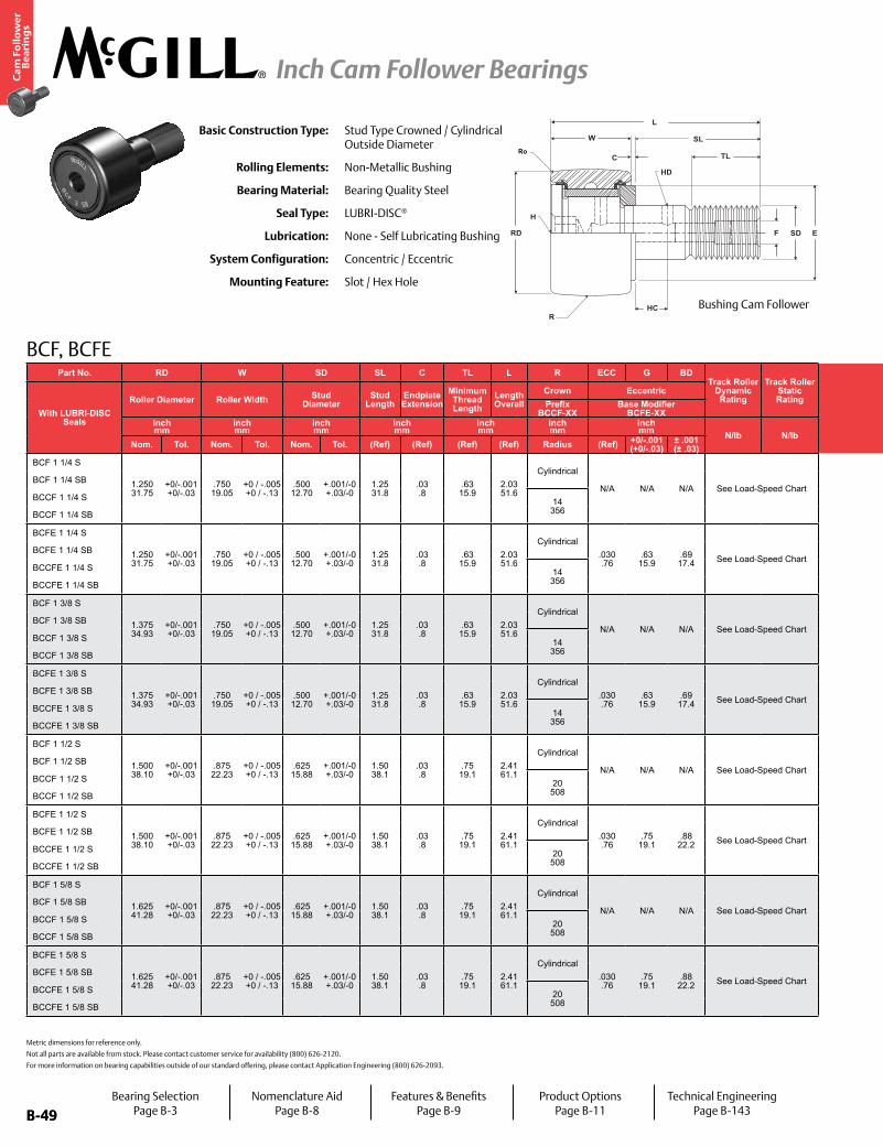
B-49
Ca
m F
oll
ow
er
Be
ari
ng
s
Inch Cam Follower Bearings
B-49
Part No. RD W SD SL C TL L R ECC G BDTrack Roller
Dynamic Rating
Track Roller Static Rating
Part No. HC HD F H E Ro
Housing Bore Diameter Thread
Type
Clamping Torque
Limiting Speed
WT
With LUBRI-DISC Seals
Roller Diameter Roller Width Stud Diameter
Stud Length
Endplate Extension
Minimum Thread Length
Length Overall
Crown Eccentric
With LUBRI-DISC Seals
Hole Center
Radial Hole Diameter
Axial Hole Dia
or FittingHex Hole Min Boss
DiameterOuter
Corner Radius
Bearing WeightPrefix
BCCF-XX Base Modifier
BCFE-XXinch mm
inch mm
inch mm
inch mm
inch mm
inch mm
inch mm N/lb N/lb
inch mm
inch mm
inch mm
inch mm in-lb
Nm RPM lbkgNom. Tol. Nom. Tol. Nom. Tol. (Ref) (Ref) (Ref) (Ref) Radius (Ref) +0/-.001
(+0/-.03)± .001 (± .03) (Ref) (Ref) (Ref) (Ref) (Ref) (Ref) Nom. Tol.
BCF 1 1/4 S
1.250 31.75
+0/-.001 +0/-.03
.750 19.05
+0 / -.005 +0 / -.13
.500 12.70
+.001/-0 +.03/-0
1.25 31.8
.03 .8
.63 15.9
2.03 51.6
Cylindrical
N/A N/A N/A See Load-Speed Chart
BCF 1 1/4 S
.31 7.9
.09 2.4
.1875 4.76
.25 6.4
.98 25.0
.03 .8
.5003 12.708
+.0002/-.0003 +.0005/-.0008 1/2-20 350
40See Load-
Speed Chart.30 .14
BCF 1 1/4 SB BCF 1 1/4 SB
BCCF 1 1/4 S 14 356
BCCF 1 1/4 SN/A
BCCF 1 1/4 SB BCCF 1 1/4 SB
BCFE 1 1/4 S
1.250 31.75
+0/-.001 +0/-.03
.750 19.05
+0 / -.005 +0 / -.13
.500 12.70
+.001/-0 +.03/-0
1.25 31.8
.03 .8
.63 15.9
2.03 51.6
Cylindrical.030 .76
.63 15.9
.69 17.4 See Load-Speed Chart
BCFE 1 1/4 S
.31 7.9
.09 2.4
.1875 4.76
.25 6.4
.98 25.0
.03 .8
.690 17.52
+.001/-.001 +.025/-.025 1/2-20 350
40See Load-
Speed Chart.30 .14
BCFE 1 1/4 SB BCFE 1 1/4 SB
BCCFE 1 1/4 S 14 356
BCCFE 1 1/4 SN/A
BCCFE 1 1/4 SB BCCFE 1 1/4 SB
BCF 1 3/8 S
1.375 34.93
+0/-.001 +0/-.03
.750 19.05
+0 / -.005 +0 / -.13
.500 12.70
+.001/-0 +.03/-0
1.25 31.8
.03 .8
.63 15.9
2.03 51.6
Cylindrical
N/A N/A N/A See Load-Speed Chart
BCF 1 3/8 S
.31 7.9
.09 2.4
.1875 4.76
.25 6.4
.98 25.0
.05 1.2
.5003 12.708
+.0002/-.0003 +.0005/-.0008 1/2-20 350
40See Load-
Speed Chart.35 .16
BCF 1 3/8 SB BCF 1 3/8 SB
BCCF 1 3/8 S 14 356
BCCF 1 3/8 SN/A
BCCF 1 3/8 SB BCCF 1 3/8 SB
BCFE 1 3/8 S
1.375 34.93
+0/-.001 +0/-.03
.750 19.05
+0 / -.005 +0 / -.13
.500 12.70
+.001/-0 +.03/-0
1.25 31.8
.03 .8
.63 15.9
2.03 51.6
Cylindrical.030 .76
.63 15.9
.69 17.4 See Load-Speed Chart
BCFE 1 3/8 S
.31 7.9
.09 2.4
.1875 4.76
.25 6.4
.98 25.0
.05 1.2
.690 17.52
+.001/-.001 +.025/-.025 1/2-20 350
40See Load-
Speed Chart.35 .16
BCFE 1 3/8 SB BCFE 1 3/8 SB
BCCFE 1 3/8 S 14 356
BCCFE 1 3/8 SN/A
BCCFE 1 3/8 SB BCCFE 1 3/8 SB
BCF 1 1/2 S
1.500 38.10
+0/-.001 +0/-.03
.875 22.23
+0 / -.005 +0 / -.13
.625 15.88
+.001/-0 +.03/-0
1.50 38.1
.03 .8
.75 19.1
2.41 61.1
Cylindrical
N/A N/A N/A See Load-Speed Chart
BCF 1 1/2 S
.38 9.5
.09 2.4
.1875 4.76
.31 7.9
1.09 27.8
.06 1.6
.6253 15.883
+.0002/-.0003 +.0005/-.0008 5/8-18 650
73See Load-
Speed Chart.53 .24
BCF 1 1/2 SB BCF 1 1/2 SB
BCCF 1 1/2 S 20 508
BCCF 1 1/2 SN/A
BCCF 1 1/2 SB BCCF 1 1/2 SB
BCFE 1 1/2 S
1.500 38.10
+0/-.001 +0/-.03
.875 22.23
+0 / -.005 +0 / -.13
.625 15.88
+.001/-0 +.03/-0
1.50 38.1
.03 .8
.75 19.1
2.41 61.1
Cylindrical.030 .76
.75 19.1
.88 22.2 See Load-Speed Chart
BCFE 1 1/2 S
.38 9.5
.09 2.4
.1875 4.76
.31 7.9
1.09 27.8
.06 1.6
.878 22.30
+.001/-.001 +.025/-.025 5/8-18 650
73See Load-
Speed Chart.53 .24
BCFE 1 1/2 SB BCFE 1 1/2 SB
BCCFE 1 1/2 S 20 508
BCCFE 1 1/2 SN/A
BCCFE 1 1/2 SB BCCFE 1 1/2 SB
BCF 1 5/8 S
1.625 41.28
+0/-.001 +0/-.03
.875 22.23
+0 / -.005 +0 / -.13
.625 15.88
+.001/-0 +.03/-0
1.50 38.1
.03 .8
.75 19.1
2.41 61.1
Cylindrical
N/A N/A N/A See Load-Speed Chart
BCF 1 5/8 S
.38 9.5
.09 2.4
.1875 4.76
.31 7.9
1.09 27.8
.06 1.6
.6253 15.883
+.0002/-.0003 +.0005/-.0008 5/8-18 650
73See Load-
Speed Chart.60 .27
BCF 1 5/8 SB BCF 1 5/8 SB
BCCF 1 5/8 S 20 508
BCCF 1 5/8 SN/A
BCCF 1 5/8 SB BCCF 1 5/8 SB
BCFE 1 5/8 S
1.625 41.28
+0/-.001 +0/-.03
.875 22.23
+0 / -.005 +0 / -.13
.625 15.88
+.001/-0 +.03/-0
1.50 38.1
.03 .8
.75 19.1
2.41 61.1
Cylindrical.030 .76
.75 19.1
.88 22.2 See Load-Speed Chart
BCFE 1 5/8 S
.38 9.5
.09 2.4
.1875 4.76
.31 7.9
1.09 27.8
.06 1.6
.878 22.30
+.001/-.001 +.025/-.025 5/8-18 650
73See Load-
Speed Chart.60 .27
BCFE 1 5/8 SB BCFE 1 5/8 SB
BCCFE 1 5/8 S 20 508
BCCFE 1 5/8 SN/A
BCCFE 1 5/8 SB BCCFE 1 5/8 SB
Metric dimensions for reference only.
Not all parts are available from stock. Please contact customer service for availability (800) 626-2120.
For more information on bearing capabilities outside of our standard offering, please contact Application Engineering (800) 626-2093.
BCF, BCFE
Basic Construction Type: Stud Type Crowned / Cylindrical Outside Diameter
Rolling Elements: Non-Metallic Bushing
Bearing Material: Bearing Quality Steel
Seal Type: LUBRI-DISC®
Lubrication: None - Self Lubricating Bushing
System Configuration: Concentric / Eccentric
Mounting Feature: Slot / Hex Hole
RD
W
C
SL
TL
HD
H
HC
F SD E
R
Ro
L
Bushing Cam Follower
Bearing SelectionPage B-3
Nomenclature AidPage B-8
Features & BenefitsPage B-9
Product OptionsPage B-11
Technical EngineeringPage B-143

B-50
Ca
m F
oll
ow
er
Be
ari
ng
s
Inch Cam Follower Bearings
B-50
Part No. RD W SD SL C TL L R ECC G BDTrack Roller
Dynamic Rating
Track Roller Static Rating
Part No. HC HD F H E Ro
Housing Bore Diameter Thread
Type
Clamping Torque
Limiting Speed
WT
With LUBRI-DISC Seals
Roller Diameter Roller Width Stud Diameter
Stud Length
Endplate Extension
Minimum Thread Length
Length Overall
Crown Eccentric
With LUBRI-DISC Seals
Hole Center
Radial Hole Diameter
Axial Hole Dia
or FittingHex Hole Min Boss
DiameterOuter
Corner Radius
Bearing WeightPrefix
BCCF-XX Base Modifier
BCFE-XXinch mm
inch mm
inch mm
inch mm
inch mm
inch mm
inch mm N/lb N/lb
inch mm
inch mm
inch mm
inch mm in-lb
Nm RPM lbkgNom. Tol. Nom. Tol. Nom. Tol. (Ref) (Ref) (Ref) (Ref) Radius (Ref) +0/-.001
(+0/-.03)± .001 (± .03) (Ref) (Ref) (Ref) (Ref) (Ref) (Ref) Nom. Tol.
BCF 1 1/4 S
1.250 31.75
+0/-.001 +0/-.03
.750 19.05
+0 / -.005 +0 / -.13
.500 12.70
+.001/-0 +.03/-0
1.25 31.8
.03 .8
.63 15.9
2.03 51.6
Cylindrical
N/A N/A N/A See Load-Speed Chart
BCF 1 1/4 S
.31 7.9
.09 2.4
.1875 4.76
.25 6.4
.98 25.0
.03 .8
.5003 12.708
+.0002/-.0003 +.0005/-.0008 1/2-20 350
40See Load-
Speed Chart.30 .14
BCF 1 1/4 SB BCF 1 1/4 SB
BCCF 1 1/4 S 14 356
BCCF 1 1/4 SN/A
BCCF 1 1/4 SB BCCF 1 1/4 SB
BCFE 1 1/4 S
1.250 31.75
+0/-.001 +0/-.03
.750 19.05
+0 / -.005 +0 / -.13
.500 12.70
+.001/-0 +.03/-0
1.25 31.8
.03 .8
.63 15.9
2.03 51.6
Cylindrical.030 .76
.63 15.9
.69 17.4 See Load-Speed Chart
BCFE 1 1/4 S
.31 7.9
.09 2.4
.1875 4.76
.25 6.4
.98 25.0
.03 .8
.690 17.52
+.001/-.001 +.025/-.025 1/2-20 350
40See Load-
Speed Chart.30 .14
BCFE 1 1/4 SB BCFE 1 1/4 SB
BCCFE 1 1/4 S 14 356
BCCFE 1 1/4 SN/A
BCCFE 1 1/4 SB BCCFE 1 1/4 SB
BCF 1 3/8 S
1.375 34.93
+0/-.001 +0/-.03
.750 19.05
+0 / -.005 +0 / -.13
.500 12.70
+.001/-0 +.03/-0
1.25 31.8
.03 .8
.63 15.9
2.03 51.6
Cylindrical
N/A N/A N/A See Load-Speed Chart
BCF 1 3/8 S
.31 7.9
.09 2.4
.1875 4.76
.25 6.4
.98 25.0
.05 1.2
.5003 12.708
+.0002/-.0003 +.0005/-.0008 1/2-20 350
40See Load-
Speed Chart.35 .16
BCF 1 3/8 SB BCF 1 3/8 SB
BCCF 1 3/8 S 14 356
BCCF 1 3/8 SN/A
BCCF 1 3/8 SB BCCF 1 3/8 SB
BCFE 1 3/8 S
1.375 34.93
+0/-.001 +0/-.03
.750 19.05
+0 / -.005 +0 / -.13
.500 12.70
+.001/-0 +.03/-0
1.25 31.8
.03 .8
.63 15.9
2.03 51.6
Cylindrical.030 .76
.63 15.9
.69 17.4 See Load-Speed Chart
BCFE 1 3/8 S
.31 7.9
.09 2.4
.1875 4.76
.25 6.4
.98 25.0
.05 1.2
.690 17.52
+.001/-.001 +.025/-.025 1/2-20 350
40See Load-
Speed Chart.35 .16
BCFE 1 3/8 SB BCFE 1 3/8 SB
BCCFE 1 3/8 S 14 356
BCCFE 1 3/8 SN/A
BCCFE 1 3/8 SB BCCFE 1 3/8 SB
BCF 1 1/2 S
1.500 38.10
+0/-.001 +0/-.03
.875 22.23
+0 / -.005 +0 / -.13
.625 15.88
+.001/-0 +.03/-0
1.50 38.1
.03 .8
.75 19.1
2.41 61.1
Cylindrical
N/A N/A N/A See Load-Speed Chart
BCF 1 1/2 S
.38 9.5
.09 2.4
.1875 4.76
.31 7.9
1.09 27.8
.06 1.6
.6253 15.883
+.0002/-.0003 +.0005/-.0008 5/8-18 650
73See Load-
Speed Chart.53 .24
BCF 1 1/2 SB BCF 1 1/2 SB
BCCF 1 1/2 S 20 508
BCCF 1 1/2 SN/A
BCCF 1 1/2 SB BCCF 1 1/2 SB
BCFE 1 1/2 S
1.500 38.10
+0/-.001 +0/-.03
.875 22.23
+0 / -.005 +0 / -.13
.625 15.88
+.001/-0 +.03/-0
1.50 38.1
.03 .8
.75 19.1
2.41 61.1
Cylindrical.030 .76
.75 19.1
.88 22.2 See Load-Speed Chart
BCFE 1 1/2 S
.38 9.5
.09 2.4
.1875 4.76
.31 7.9
1.09 27.8
.06 1.6
.878 22.30
+.001/-.001 +.025/-.025 5/8-18 650
73See Load-
Speed Chart.53 .24
BCFE 1 1/2 SB BCFE 1 1/2 SB
BCCFE 1 1/2 S 20 508
BCCFE 1 1/2 SN/A
BCCFE 1 1/2 SB BCCFE 1 1/2 SB
BCF 1 5/8 S
1.625 41.28
+0/-.001 +0/-.03
.875 22.23
+0 / -.005 +0 / -.13
.625 15.88
+.001/-0 +.03/-0
1.50 38.1
.03 .8
.75 19.1
2.41 61.1
Cylindrical
N/A N/A N/A See Load-Speed Chart
BCF 1 5/8 S
.38 9.5
.09 2.4
.1875 4.76
.31 7.9
1.09 27.8
.06 1.6
.6253 15.883
+.0002/-.0003 +.0005/-.0008 5/8-18 650
73See Load-
Speed Chart.60 .27
BCF 1 5/8 SB BCF 1 5/8 SB
BCCF 1 5/8 S 20 508
BCCF 1 5/8 SN/A
BCCF 1 5/8 SB BCCF 1 5/8 SB
BCFE 1 5/8 S
1.625 41.28
+0/-.001 +0/-.03
.875 22.23
+0 / -.005 +0 / -.13
.625 15.88
+.001/-0 +.03/-0
1.50 38.1
.03 .8
.75 19.1
2.41 61.1
Cylindrical.030 .76
.75 19.1
.88 22.2 See Load-Speed Chart
BCFE 1 5/8 S
.38 9.5
.09 2.4
.1875 4.76
.31 7.9
1.09 27.8
.06 1.6
.878 22.30
+.001/-.001 +.025/-.025 5/8-18 650
73See Load-
Speed Chart.60 .27
BCFE 1 5/8 SB BCFE 1 5/8 SB
BCCFE 1 5/8 S 20 508
BCCFE 1 5/8 SN/A
BCCFE 1 5/8 SB BCCFE 1 5/8 SB
BCF, BCFE
FRD
C
W SL
TL
F BD E
G
BEARINGCENTERLINEECC
L
SD
R
Ro
HD
HC Bushing Cam Follower with Eccentric Bushing
Bearing SelectionPage B-3
Nomenclature AidPage B-8
Features & BenefitsPage B-9
Product OptionsPage B-11
Technical EngineeringPage B-143

B-51
Ca
m F
oll
ow
er
Be
ari
ng
s
Inch Cam Follower Bearings
B-51
Part No. RD W SD SL C TL L R ECC G BDTrack Roller
Dynamic Rating
Track Roller Static Rating
Part No. HC HD F H E Ro
Housing Bore Diameter Thread
Type
Clamping Torque
Limiting Speed
WT
With LUBRI-DISC Seals
Roller Diameter Roller Width Stud Diameter
Stud Length
Endplate Extension
Minimum Thread Length
Length Overall
Crown Eccentric
With LUBRI-DISC Seals
Hole Center
Radial Hole Diameter
Axial Hole Dia
or FittingHex Hole Min Boss
DiameterOuter
Corner Radius
Bearing WeightPrefix
BCCF-XX Base Modifier
BCFE-XXinch mm
inch mm
inch mm
inch mm
inch mm
inch mm
inch mm N/lb N/lb
inch mm
inch mm
inch mm
inch mm in-lb
Nm RPM lbkgNom. Tol. Nom. Tol. Nom. Tol. (Ref) (Ref) (Ref) (Ref) Radius (Ref) +0/-.001
(+0/-.03)± .001 (± .03) (Ref) (Ref) (Ref) (Ref) (Ref) (Ref) Nom. Tol.
BCF 1 3/4 S
1.750 44.45
+0/-.001 +0/-.03
1.000 25.40
0 / -.005 +0 / -.13
.750 19.05
+.001/-0 +.03/-0
1.75 44.5
.03 .8
.88 22.2
2.78 70.6
Cylindrical
N/A N/A N/A See Load-Speed Chart
BCF 1 3/4 S
.44 11.1
.125 3
.1875 4.76
.31 7.9
1.25 31.8
.06 1.6
.7503 19.058
+.0002/-.0003 +.0005/-.0008 3/4-16 1,250
141See Load-
Speed Chart.84 .38
BCF 1 3/4 SB BCF 1 3/4 SB
BCCF 1 3/4 S 20 508
BCCF 1 3/4 SN/A
BCCF 1 3/4 SB BCCF 1 3/4 SB
BCFE 1 3/4 S
1.750 44.45
+0/-.001 +0/-.03
1.000 25.40
0 / -.005 +0 / -.13
.750 19.05
+.001/-0 +.03/-0
1.75 44.5
.03 .8
.88 22.2
2.78 70.6
Cylindrical.030 .76
.88 22.2
.00 25.4 See Load-Speed Chart
BCFE 1 3/4 S
.44 11.1
.125 3
.1875 4.76
.31 7.9
1.25 31.8
.06 1.6
1.003 25.47
+.001/-.001 +.025/-.025 3/4-16 1,250
141See Load-
Speed Chart.84 .38
BCFE 1 3/4 SB BCFE 1 3/4 SB
BCCFE 1 3/4 S 20 508
BCCFE 1 3/4 SN/A
BCCFE 1 3/4 SB BCCFE 1 3/4 SB
BCF 1 7/8 S
1.875 47.63
+0/-.001 +0/-.03
1.000 25.40
0 / -.005 +0 / -.13
.750 19.05
+.001/-0 +.03/-0
1.75 44.5
.03 .8
.88 22.2
2.78 70.6
Cylindrical
N/A N/A N/A See Load-Speed Chart
BCF 1 7/8 S
.44 11.1
.125 3
.1875 4.76
.31 7.9
1.25 31.8
.06 1.6
.7503 19.058
+.0002/-.0003 +.0005/-.0008 3/4-16 1,250
141See Load-
Speed Chart.95 .43
BCF 1 7/8 SB BCF 1 7/8 SB
BCCF 1 7/8 S 20 508
BCCF 1 7/8 SN/A
BCCF 1 7/8 SB BCCF 1 7/8 SB
BCFE 1 7/8 S
1.875 47.63
+0/-.001 +0/-.03
1.000 25.40
0 / -.005 +0 / -.13
.750 19.05
+.001/-0 +.03/-0
1.75 44.5
.03 .8
.88 22.2
2.78 70.6
Cylindrical.030 .76
.88 22.2
.00 25.4 See Load-Speed Chart
BCFE 1 7/8 S
.44 11.1
.125 3
.1875 4.76
.31 7.9
1.25 31.8
.06 1.6
1.003 25.47
+.001/-.001 +.025/-.025 3/4-16 1,250
141See Load-
Speed Chart.95 .43
BCFE 1 7/8 SB BCFE 1 7/8 SB
BCCFE 1 7/8 S 20 508
BCCFE 1 7/8 SN/A
BCCFE 1 7/8 SB BCCFE 1 7/8 SB
BCF 2 S
2.000 50.80
+0/-.001 +0/-.03
1.250 31.75
0 / -.005 +0 / -.13
.875 22.23
+.001/-0 +.03/-0
2.00 50.8
.03 .8
2.00 50.8
3.28 83.3
Cylindrical
N/A N/A N/A See Load-Speed Chart
BCF 2 S
.50 12.7
.125 3
.1875 4.76
.44 11.1
1.41 35.7
.09 2.4
.8753 22.233
+.0002/-.0003 +.0005/-.0008 7/8-14 1,500
170See Load-
Speed Chart1.36 .62
BCF 2 SB BCF 2 SB
BCCF 2 S 24 610
BCCF 2 SN/A
BCCF 2 SB BCCF 2 SB
BCFE 2 S
2.000 50.80
+0/-.001 +0/-.03
1.250 31.75
0 / -.005 +0 / -.13
.875 22.23
+.001/-0 +.03/-0
2.00 50.8
.03 .8
2.00 50.8
3.28 83.3
Cylindrical.030 .76
.00 25.4
.19 30.1 See Load-Speed Chart
BCFE 2 S
.50 12.7
.125 3
.1875 4.76
.44 11.1
1.41 35.7
.09 2.4
1.190 30.22
+.001/-.001 +.025/-.025 7/8-14 1,500
170See Load-
Speed Chart1.36 .62
BCFE 2 SB BCFE 2 SB
BCCFE 2 S 24 610
BCCFE 2 SN/A
BCCFE 2 SB BCCFE 2 SB
BCF 2 1/4 S
2.250 57.15
+0/-.001 +0/-.03
1.250 31.75
0 / -.005 +0 / -.13
.875 22.23
+.001/-0 +.03/-0
2.00 50.8
.03 .8
2.00 50.8
3.28 83.3
Cylindrical
N/A N/A N/A See Load-Speed Chart
BCF 2 1/4 S
.50 12.7
.125 3
.1875 4.76
.44 11.1
1.41 35.7
.09 2.4
.8753 22.233
+.0002/-.0003 +.0005/-.0008 7/8-14 1,500
170See Load-
Speed Chart1.65 .75
BCF 2 1/4 SB BCF 2 1/4 SB
BCCF 2 1/4 S 24 610
BCCF 2 1/4 SN/A
BCCF 2 1/4 SB BCCF 2 1/4 SB
BCFE 2 1/4 S
2.250 57.15
+0/-.001 +0/-.03
1.250 31.75
0 / -.005 +0 / -.13
.875 22.23
+.001/-0 +.03/-0
2.00 50.8
.03 .8
2.00 50.8
3.28 83.3
Cylindrical.030 .76
.00 25.4
.19 30.1 See Load-Speed Chart
BCFE 2 1/4 S
.50 12.7
.125 3
.1875 4.76
.44 11.1
1.41 35.7
.09 2.4
.8753 22.233
+.001/-.001 +.025/-.025 7/8-14 1,500
170See Load-
Speed Chart1.65 .75
BCFE 2 1/4 SB BCFE 2 1/4 SB
BCCFE 2 1/4 S 24 610
BCCFE 2 1/4 SN/A
BCCFE 2 1/4 SB BCCFE 2 1/4 SB
Metric dimensions for reference only.
Not all parts are available from stock. Please contact customer service for availability (800) 626-2120.
For more information on bearing capabilities outside of our standard offering, please contact Application Engineering (800) 626-2093.
BCF, BCFE
Basic Construction Type: Stud Type Crowned / Cylindrical Outside Diameter
Rolling Elements: Non-Metallic Bushing
Bearing Material: Bearing Quality Steel
Seal Type: LUBRI-DISC®
Lubrication: None - Self Lubricating Bushing
System Configuration: Concentric / Eccentric
Mounting Feature: Slot / Hex Hole
RD
W
C
SL
TL
HD
H
HC
F SD E
R
Ro
L
Bushing Cam Follower
Bearing SelectionPage B-3
Nomenclature AidPage B-8
Features & BenefitsPage B-9
Product OptionsPage B-11
Technical EngineeringPage B-143

B-52
Ca
m F
oll
ow
er
Be
ari
ng
s
Inch Cam Follower Bearings
B-52
Part No. RD W SD SL C TL L R ECC G BDTrack Roller
Dynamic Rating
Track Roller Static Rating
Part No. HC HD F H E Ro
Housing Bore Diameter Thread
Type
Clamping Torque
Limiting Speed
WT
With LUBRI-DISC Seals
Roller Diameter Roller Width Stud Diameter
Stud Length
Endplate Extension
Minimum Thread Length
Length Overall
Crown Eccentric
With LUBRI-DISC Seals
Hole Center
Radial Hole Diameter
Axial Hole Dia
or FittingHex Hole Min Boss
DiameterOuter
Corner Radius
Bearing WeightPrefix
BCCF-XX Base Modifier
BCFE-XXinch mm
inch mm
inch mm
inch mm
inch mm
inch mm
inch mm N/lb N/lb
inch mm
inch mm
inch mm
inch mm in-lb
Nm RPM lbkgNom. Tol. Nom. Tol. Nom. Tol. (Ref) (Ref) (Ref) (Ref) Radius (Ref) +0/-.001
(+0/-.03)± .001 (± .03) (Ref) (Ref) (Ref) (Ref) (Ref) (Ref) Nom. Tol.
BCF 1 3/4 S
1.750 44.45
+0/-.001 +0/-.03
1.000 25.40
0 / -.005 +0 / -.13
.750 19.05
+.001/-0 +.03/-0
1.75 44.5
.03 .8
.88 22.2
2.78 70.6
Cylindrical
N/A N/A N/A See Load-Speed Chart
BCF 1 3/4 S
.44 11.1
.125 3
.1875 4.76
.31 7.9
1.25 31.8
.06 1.6
.7503 19.058
+.0002/-.0003 +.0005/-.0008 3/4-16 1,250
141See Load-
Speed Chart.84 .38
BCF 1 3/4 SB BCF 1 3/4 SB
BCCF 1 3/4 S 20 508
BCCF 1 3/4 SN/A
BCCF 1 3/4 SB BCCF 1 3/4 SB
BCFE 1 3/4 S
1.750 44.45
+0/-.001 +0/-.03
1.000 25.40
0 / -.005 +0 / -.13
.750 19.05
+.001/-0 +.03/-0
1.75 44.5
.03 .8
.88 22.2
2.78 70.6
Cylindrical.030 .76
.88 22.2
.00 25.4 See Load-Speed Chart
BCFE 1 3/4 S
.44 11.1
.125 3
.1875 4.76
.31 7.9
1.25 31.8
.06 1.6
1.003 25.47
+.001/-.001 +.025/-.025 3/4-16 1,250
141See Load-
Speed Chart.84 .38
BCFE 1 3/4 SB BCFE 1 3/4 SB
BCCFE 1 3/4 S 20 508
BCCFE 1 3/4 SN/A
BCCFE 1 3/4 SB BCCFE 1 3/4 SB
BCF 1 7/8 S
1.875 47.63
+0/-.001 +0/-.03
1.000 25.40
0 / -.005 +0 / -.13
.750 19.05
+.001/-0 +.03/-0
1.75 44.5
.03 .8
.88 22.2
2.78 70.6
Cylindrical
N/A N/A N/A See Load-Speed Chart
BCF 1 7/8 S
.44 11.1
.125 3
.1875 4.76
.31 7.9
1.25 31.8
.06 1.6
.7503 19.058
+.0002/-.0003 +.0005/-.0008 3/4-16 1,250
141See Load-
Speed Chart.95 .43
BCF 1 7/8 SB BCF 1 7/8 SB
BCCF 1 7/8 S 20 508
BCCF 1 7/8 SN/A
BCCF 1 7/8 SB BCCF 1 7/8 SB
BCFE 1 7/8 S
1.875 47.63
+0/-.001 +0/-.03
1.000 25.40
0 / -.005 +0 / -.13
.750 19.05
+.001/-0 +.03/-0
1.75 44.5
.03 .8
.88 22.2
2.78 70.6
Cylindrical.030 .76
.88 22.2
.00 25.4 See Load-Speed Chart
BCFE 1 7/8 S
.44 11.1
.125 3
.1875 4.76
.31 7.9
1.25 31.8
.06 1.6
1.003 25.47
+.001/-.001 +.025/-.025 3/4-16 1,250
141See Load-
Speed Chart.95 .43
BCFE 1 7/8 SB BCFE 1 7/8 SB
BCCFE 1 7/8 S 20 508
BCCFE 1 7/8 SN/A
BCCFE 1 7/8 SB BCCFE 1 7/8 SB
BCF 2 S
2.000 50.80
+0/-.001 +0/-.03
1.250 31.75
0 / -.005 +0 / -.13
.875 22.23
+.001/-0 +.03/-0
2.00 50.8
.03 .8
2.00 50.8
3.28 83.3
Cylindrical
N/A N/A N/A See Load-Speed Chart
BCF 2 S
.50 12.7
.125 3
.1875 4.76
.44 11.1
1.41 35.7
.09 2.4
.8753 22.233
+.0002/-.0003 +.0005/-.0008 7/8-14 1,500
170See Load-
Speed Chart1.36 .62
BCF 2 SB BCF 2 SB
BCCF 2 S 24 610
BCCF 2 SN/A
BCCF 2 SB BCCF 2 SB
BCFE 2 S
2.000 50.80
+0/-.001 +0/-.03
1.250 31.75
0 / -.005 +0 / -.13
.875 22.23
+.001/-0 +.03/-0
2.00 50.8
.03 .8
2.00 50.8
3.28 83.3
Cylindrical.030 .76
.00 25.4
.19 30.1 See Load-Speed Chart
BCFE 2 S
.50 12.7
.125 3
.1875 4.76
.44 11.1
1.41 35.7
.09 2.4
1.190 30.22
+.001/-.001 +.025/-.025 7/8-14 1,500
170See Load-
Speed Chart1.36 .62
BCFE 2 SB BCFE 2 SB
BCCFE 2 S 24 610
BCCFE 2 SN/A
BCCFE 2 SB BCCFE 2 SB
BCF 2 1/4 S
2.250 57.15
+0/-.001 +0/-.03
1.250 31.75
0 / -.005 +0 / -.13
.875 22.23
+.001/-0 +.03/-0
2.00 50.8
.03 .8
2.00 50.8
3.28 83.3
Cylindrical
N/A N/A N/A See Load-Speed Chart
BCF 2 1/4 S
.50 12.7
.125 3
.1875 4.76
.44 11.1
1.41 35.7
.09 2.4
.8753 22.233
+.0002/-.0003 +.0005/-.0008 7/8-14 1,500
170See Load-
Speed Chart1.65 .75
BCF 2 1/4 SB BCF 2 1/4 SB
BCCF 2 1/4 S 24 610
BCCF 2 1/4 SN/A
BCCF 2 1/4 SB BCCF 2 1/4 SB
BCFE 2 1/4 S
2.250 57.15
+0/-.001 +0/-.03
1.250 31.75
0 / -.005 +0 / -.13
.875 22.23
+.001/-0 +.03/-0
2.00 50.8
.03 .8
2.00 50.8
3.28 83.3
Cylindrical.030 .76
.00 25.4
.19 30.1 See Load-Speed Chart
BCFE 2 1/4 S
.50 12.7
.125 3
.1875 4.76
.44 11.1
1.41 35.7
.09 2.4
.8753 22.233
+.001/-.001 +.025/-.025 7/8-14 1,500
170See Load-
Speed Chart1.65 .75
BCFE 2 1/4 SB BCFE 2 1/4 SB
BCCFE 2 1/4 S 24 610
BCCFE 2 1/4 SN/A
BCCFE 2 1/4 SB BCCFE 2 1/4 SB
BCF, BCFE
FRD
C
W SL
TL
F BD E
G
BEARINGCENTERLINEECC
L
SD
R
Ro
HD
HC Bushing Cam Follower with Eccentric Bushing
Bearing SelectionPage B-3
Nomenclature AidPage B-8
Features & BenefitsPage B-9
Product OptionsPage B-11
Technical EngineeringPage B-143

B-53
Ca
m F
oll
ow
er
Be
ari
ng
s
Inch Cam Follower Bearings
B-53
Part No. RD W SD SL C TL L R ECC G BDTrack Roller
Dynamic Rating
Track Roller Static Rating
Part No. HC HD F H E Ro
Housing Bore Diameter Thread
Type
Clamping Torque
Limiting Speed
WT
With LUBRI-DISC Seals
Roller Diameter Roller Width Stud Diameter
Stud Length
Endplate Extension
Minimum Thread Length
Length Overall
Crown Eccentric
With LUBRI-DISC Seals
Hole Center
Radial Hole Diameter
Axial Hole Dia
or FittingHex Hole Min Boss
DiameterOuter
Corner Radius
Bearing WeightPrefix
BCCF-XX Base Modifier
BCFE-XXinch mm
inch mm
inch mm
inch mm
inch mm
inch mm
inch mm N/lb N/lb
inch mm
inch mm
inch mm
inch mm in-lb
Nm RPM lbkgNom. Tol. Nom. Tol. Nom. Tol. (Ref) (Ref) (Ref) (Ref) Radius (Ref) +0/-.001
(+0/-.03)± .001 (± .03) (Ref) (Ref) (Ref) (Ref) (Ref) (Ref) Nom. Tol.
BCF 2 1/2 S
2.500 63.50
+0/-.001 +0/-.03
1.500 38.10
+0 / -.005 +0 / -.13
1.000 25.40
+.001/-0 +.03/-0
2.25 57.2
.03 .8
2.25 57.2
3.78 96.0
Cylindrical
N/A N/A N/A See Load-Speed Chart
BCF 2 1/2 S
.56 14.3
.125 3
.1875 4.76
.50 12.7
1.69 42.9
.09 2.4
1.0003 25.408
+.0002/-.0003 +.0005/-.0008 1-14 2,250
254See Load-
Speed Chart2.50 1.13
BCF 2 1/2 SB BCF 2 1/2 SB
BCCF 2 1/2 S 30 762
BCCF 2 1/2 SN/A
BCCF 2 1/2 SB BCCF 2 1/2 SB
BCFE 2 1/2 S
2.500 63.50
+0/-.001 +0/-.03
1.500 38.10
+0 / -.005 +0 / -.13
1.000 25.40
+.001/-0 +.03/-0
2.25 57.2
.03 .8
2.25 57.2
3.78 96.0
Cylindrical.030 .76
.13 28.6
.38 34.9 See Load-Speed Chart
BCFE 2 1/2 S
.56 14.3
.125 3
.1875 4.76
.50 12.7
1.69 42.9
.09 2.4
1.378 35.00
+.001/-.001 +.025/-.025 1-14 2,250
254See Load-
Speed Chart2.50 1.13
BCFE 2 1/2 SB BCFE 2 1/2 SB
BCCFE 2 1/2 S 30 762
BCCFE 2 1/2 SN/A
BCCFE 2 1/2 SB BCCFE 2 1/2 SB
BCF 2 3/4 S
2.750 69.85
+0/-.001 +0/-.03
1.500 38.10
+0 / -.005 +0 / -.13
1.000 25.40
+.001/-0 +.03/-0
2.25 57.2
.03 .8
2.25 57.2
3.78 96.0
Cylindrical
N/A N/A N/A See Load-Speed Chart
BCF 2 3/4 S
.56 14.3
.125 3
.1875 4.76
.50 12.7
1.69 42.9
.09 2.4
1.0003 25.408
+.0002/-.0003 +.0005/-.0008 1-14 2,250
254See Load-
Speed Chart2.93 1.33
BCF 2 3/4 SB BCF 2 3/4 SB
BCCF 2 3/4 S 30 762
BCCF 2 3/4 SN/A
BCCF 2 3/4 SB BCCF 2 3/4 SB
BCFE 2 3/4 S
2.750 69.85
+0/-.001 +0/-.03
1.500 38.10
+0 / -.005 +0 / -.13
1.000 25.40
+.001/-0 +.03/-0
2.25 57.2
.03 .8
2.25 57.2
3.78 96.0
Cylindrical.030 .76
.13 28.6
.38 34.9 See Load-Speed Chart
BCFE 2 3/4 S
.56 14.3
.125 3
.1875 4.76
.50 12.7
1.69 42.9
.09 2.4
1.378 35.00
+.001/-.001 +.025/-.025 1-14 2,250
254See Load-
Speed Chart2.93 1.33
BCFE 2 3/4 SB BCFE 2 3/4 SB
BCCFE 2 3/4 S 30 762
BCCFE 2 3/4 SN/A
BCCFE 2 3/4 SB BCCFE 2 3/4 SB
BCF 3 S
3.000 76.20
+0/-.001 +0/-.03
1.750 44.45
+0 / -.005 +0 / -.13
1.250 31.75
+.001/-0 +.03/-0
2.50 63.5
.03 .8
2.50 63.5
4.28 108.7
Cylindrical
N/A N/A N/A See Load-Speed Chart
BCF 3 S
.63 15.9
.125 3
.25 6.4
.75 19.1
2.13 54.0
.13 3.2
1.2503 31.758
+.0002/-.0003 +.0005/-.0008 1 1/4-12 3,450
390See Load-
Speed Chart4.20 1.91
BCF 3 SB BCF 3 SB
BCCF 3 S 30 762
BCCF 3 SN/A
BCCF 3 SB BCCF 3 SB
BCFE 3 S
3.000 76.20
+0/-.001 +0/-.03
1.750 44.45
+0 / -.005 +0 / -.13
1.250 31.75
+.001/-0 +.03/-0
2.50 63.5
.03 .8
2.50 63.5
4.28 108.7
Cylindrical.060 .52
.25 31.8
.75 44.5 See Load-Speed Chart
BCFE 3 S
.63 15.9
.125 3
.25 6.4
.75 19.1
2.13 54.0
.13 3.2
1.753 44.52
+.001/-.001 +.025/-.025 1 1/4-12 3,450
390See Load-
Speed Chart4.20 1.91
BCFE 3 SB BCFE 3 SB
BCCFE 3 S 30 762
BCCFE 3 SN/A
BCCFE 3 SB BCCFE 3 SB
BCF 3 1/4 S
3.250 82.55
+0/-.001 +0/-.03
1.750 44.45
+0 / -.005 +0 / -.13
1.250 31.75
+.001/-0 +.03/-0
2.50 63.5
.03 .8
2.50 63.5
4.28 108.7
Cylindrical
N/A N/A N/A See Load-Speed Chart
BCF 3 1/4 S
.63 15.9
.125 3
.25 6.4
.75 19.1
2.13 54.0
.13 3.2
1.2503 31.758
+.0002/-.0003 +.0005/-.0008 1 1/4-12 3,450
390See Load-
Speed Chart4.81 2.18
BCF 3 1/4 SB BCF 3 1/4 SB
BCCF 3 1/4 S 30 762
BCCF 3 1/4 SN/A
BCCF 3 1/4 SB BCCF 3 1/4 SB
BCFE 3 1/4 S
3.250 82.55
+0/-.001 +0/-.03
1.750 44.45
+0 / -.005 +0 / -.13
1.250 31.75
+.001/-0 +.03/-0
2.50 63.5
.03 .8
2.50 63.5
4.28 108.7
Cylindrical.060 .52
.25 31.8
.75 44.5 See Load-Speed Chart
BCFE 3 1/4 S
.63 15.9
.125 3
.25 6.4
.75 19.1
2.13 54.0
.13 3.2
1.753 44.52
+.001/-.001 +.025/-.025 1 1/4-12 3,450
390See Load-
Speed Chart4.81 2.18
BCFE 3 1/4 SB BCFE 3 1/4 SB
BCCFE 3 1/4 S 30 762
BCCFE 3 1/4 SN/A
BCCFE 3 1/4 SB BCCFE 3 1/4 SB
Metric dimensions for reference only.
Not all parts are available from stock. Please contact customer service for availability (800) 626-2120.
For more information on bearing capabilities outside of our standard offering, please contact Application Engineering (800) 626-2093.
BCF, BCFE
Basic Construction Type: Stud Type Crowned / Cylindrical Outside Diameter
Rolling Elements: Non-Metallic Bushing
Bearing Material: Bearing Quality Steel
Seal Type: LUBRI-DISC®
Lubrication: None - Self Lubricating Bushing
System Configuration: Concentric / Eccentric
Mounting Feature: Slot / Hex Hole
RD
W
C
SL
TL
HD
H
HC
F SD E
R
Ro
L
Bushing Cam Follower
Bearing SelectionPage B-3
Nomenclature AidPage B-8
Features & BenefitsPage B-9
Product OptionsPage B-11
Technical EngineeringPage B-143
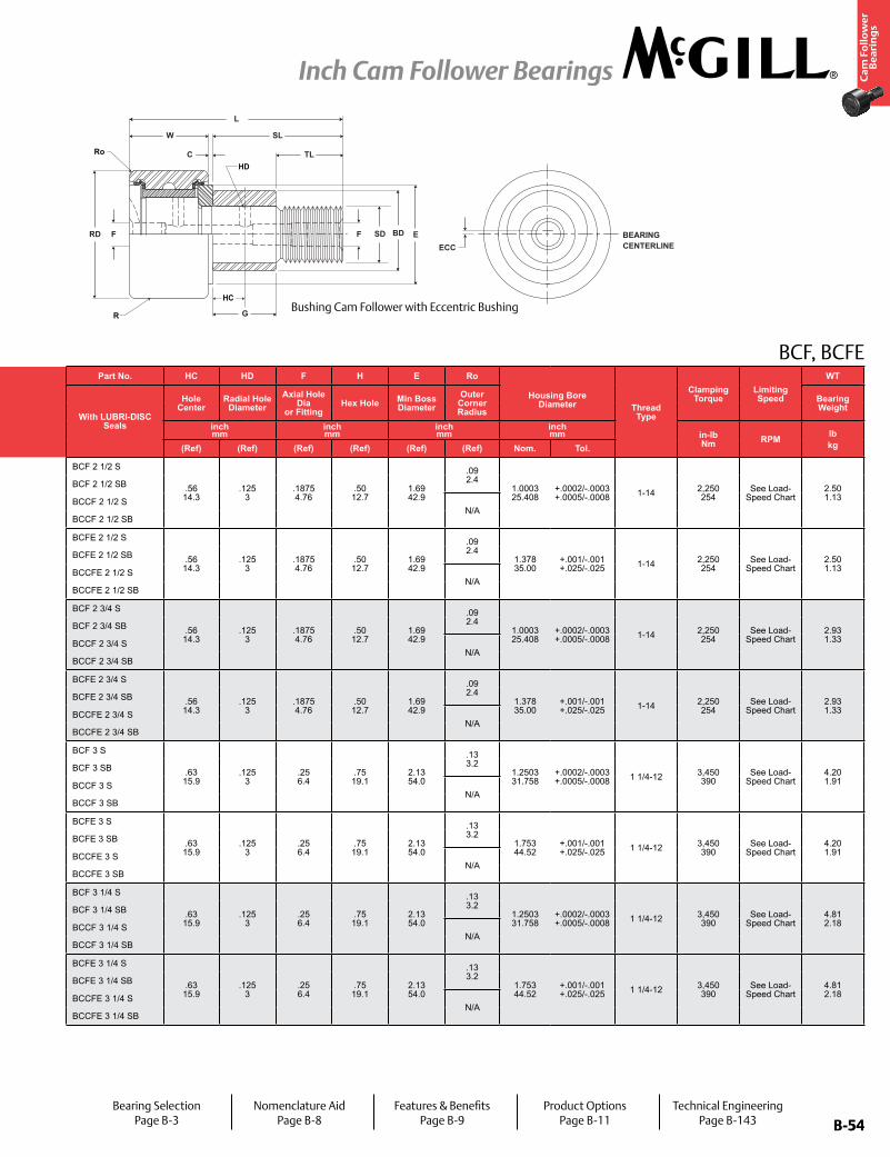
B-54
Ca
m F
oll
ow
er
Be
ari
ng
s
Inch Cam Follower Bearings
B-54
Part No. RD W SD SL C TL L R ECC G BDTrack Roller
Dynamic Rating
Track Roller Static Rating
Part No. HC HD F H E Ro
Housing Bore Diameter Thread
Type
Clamping Torque
Limiting Speed
WT
With LUBRI-DISC Seals
Roller Diameter Roller Width Stud Diameter
Stud Length
Endplate Extension
Minimum Thread Length
Length Overall
Crown Eccentric
With LUBRI-DISC Seals
Hole Center
Radial Hole Diameter
Axial Hole Dia
or FittingHex Hole Min Boss
DiameterOuter
Corner Radius
Bearing WeightPrefix
BCCF-XX Base Modifier
BCFE-XXinch mm
inch mm
inch mm
inch mm
inch mm
inch mm
inch mm N/lb N/lb
inch mm
inch mm
inch mm
inch mm in-lb
Nm RPM lbkgNom. Tol. Nom. Tol. Nom. Tol. (Ref) (Ref) (Ref) (Ref) Radius (Ref) +0/-.001
(+0/-.03)± .001 (± .03) (Ref) (Ref) (Ref) (Ref) (Ref) (Ref) Nom. Tol.
BCF 2 1/2 S
2.500 63.50
+0/-.001 +0/-.03
1.500 38.10
+0 / -.005 +0 / -.13
1.000 25.40
+.001/-0 +.03/-0
2.25 57.2
.03 .8
2.25 57.2
3.78 96.0
Cylindrical
N/A N/A N/A See Load-Speed Chart
BCF 2 1/2 S
.56 14.3
.125 3
.1875 4.76
.50 12.7
1.69 42.9
.09 2.4
1.0003 25.408
+.0002/-.0003 +.0005/-.0008 1-14 2,250
254See Load-
Speed Chart2.50 1.13
BCF 2 1/2 SB BCF 2 1/2 SB
BCCF 2 1/2 S 30 762
BCCF 2 1/2 SN/A
BCCF 2 1/2 SB BCCF 2 1/2 SB
BCFE 2 1/2 S
2.500 63.50
+0/-.001 +0/-.03
1.500 38.10
+0 / -.005 +0 / -.13
1.000 25.40
+.001/-0 +.03/-0
2.25 57.2
.03 .8
2.25 57.2
3.78 96.0
Cylindrical.030 .76
.13 28.6
.38 34.9 See Load-Speed Chart
BCFE 2 1/2 S
.56 14.3
.125 3
.1875 4.76
.50 12.7
1.69 42.9
.09 2.4
1.378 35.00
+.001/-.001 +.025/-.025 1-14 2,250
254See Load-
Speed Chart2.50 1.13
BCFE 2 1/2 SB BCFE 2 1/2 SB
BCCFE 2 1/2 S 30 762
BCCFE 2 1/2 SN/A
BCCFE 2 1/2 SB BCCFE 2 1/2 SB
BCF 2 3/4 S
2.750 69.85
+0/-.001 +0/-.03
1.500 38.10
+0 / -.005 +0 / -.13
1.000 25.40
+.001/-0 +.03/-0
2.25 57.2
.03 .8
2.25 57.2
3.78 96.0
Cylindrical
N/A N/A N/A See Load-Speed Chart
BCF 2 3/4 S
.56 14.3
.125 3
.1875 4.76
.50 12.7
1.69 42.9
.09 2.4
1.0003 25.408
+.0002/-.0003 +.0005/-.0008 1-14 2,250
254See Load-
Speed Chart2.93 1.33
BCF 2 3/4 SB BCF 2 3/4 SB
BCCF 2 3/4 S 30 762
BCCF 2 3/4 SN/A
BCCF 2 3/4 SB BCCF 2 3/4 SB
BCFE 2 3/4 S
2.750 69.85
+0/-.001 +0/-.03
1.500 38.10
+0 / -.005 +0 / -.13
1.000 25.40
+.001/-0 +.03/-0
2.25 57.2
.03 .8
2.25 57.2
3.78 96.0
Cylindrical.030 .76
.13 28.6
.38 34.9 See Load-Speed Chart
BCFE 2 3/4 S
.56 14.3
.125 3
.1875 4.76
.50 12.7
1.69 42.9
.09 2.4
1.378 35.00
+.001/-.001 +.025/-.025 1-14 2,250
254See Load-
Speed Chart2.93 1.33
BCFE 2 3/4 SB BCFE 2 3/4 SB
BCCFE 2 3/4 S 30 762
BCCFE 2 3/4 SN/A
BCCFE 2 3/4 SB BCCFE 2 3/4 SB
BCF 3 S
3.000 76.20
+0/-.001 +0/-.03
1.750 44.45
+0 / -.005 +0 / -.13
1.250 31.75
+.001/-0 +.03/-0
2.50 63.5
.03 .8
2.50 63.5
4.28 108.7
Cylindrical
N/A N/A N/A See Load-Speed Chart
BCF 3 S
.63 15.9
.125 3
.25 6.4
.75 19.1
2.13 54.0
.13 3.2
1.2503 31.758
+.0002/-.0003 +.0005/-.0008 1 1/4-12 3,450
390See Load-
Speed Chart4.20 1.91
BCF 3 SB BCF 3 SB
BCCF 3 S 30 762
BCCF 3 SN/A
BCCF 3 SB BCCF 3 SB
BCFE 3 S
3.000 76.20
+0/-.001 +0/-.03
1.750 44.45
+0 / -.005 +0 / -.13
1.250 31.75
+.001/-0 +.03/-0
2.50 63.5
.03 .8
2.50 63.5
4.28 108.7
Cylindrical.060 .52
.25 31.8
.75 44.5 See Load-Speed Chart
BCFE 3 S
.63 15.9
.125 3
.25 6.4
.75 19.1
2.13 54.0
.13 3.2
1.753 44.52
+.001/-.001 +.025/-.025 1 1/4-12 3,450
390See Load-
Speed Chart4.20 1.91
BCFE 3 SB BCFE 3 SB
BCCFE 3 S 30 762
BCCFE 3 SN/A
BCCFE 3 SB BCCFE 3 SB
BCF 3 1/4 S
3.250 82.55
+0/-.001 +0/-.03
1.750 44.45
+0 / -.005 +0 / -.13
1.250 31.75
+.001/-0 +.03/-0
2.50 63.5
.03 .8
2.50 63.5
4.28 108.7
Cylindrical
N/A N/A N/A See Load-Speed Chart
BCF 3 1/4 S
.63 15.9
.125 3
.25 6.4
.75 19.1
2.13 54.0
.13 3.2
1.2503 31.758
+.0002/-.0003 +.0005/-.0008 1 1/4-12 3,450
390See Load-
Speed Chart4.81 2.18
BCF 3 1/4 SB BCF 3 1/4 SB
BCCF 3 1/4 S 30 762
BCCF 3 1/4 SN/A
BCCF 3 1/4 SB BCCF 3 1/4 SB
BCFE 3 1/4 S
3.250 82.55
+0/-.001 +0/-.03
1.750 44.45
+0 / -.005 +0 / -.13
1.250 31.75
+.001/-0 +.03/-0
2.50 63.5
.03 .8
2.50 63.5
4.28 108.7
Cylindrical.060 .52
.25 31.8
.75 44.5 See Load-Speed Chart
BCFE 3 1/4 S
.63 15.9
.125 3
.25 6.4
.75 19.1
2.13 54.0
.13 3.2
1.753 44.52
+.001/-.001 +.025/-.025 1 1/4-12 3,450
390See Load-
Speed Chart4.81 2.18
BCFE 3 1/4 SB BCFE 3 1/4 SB
BCCFE 3 1/4 S 30 762
BCCFE 3 1/4 SN/A
BCCFE 3 1/4 SB BCCFE 3 1/4 SB
BCF, BCFE
FRD
C
W SL
TL
F BD E
G
BEARINGCENTERLINEECC
L
SD
R
Ro
HD
HC Bushing Cam Follower with Eccentric Bushing
Bearing SelectionPage B-3
Nomenclature AidPage B-8
Features & BenefitsPage B-9
Product OptionsPage B-11
Technical EngineeringPage B-143
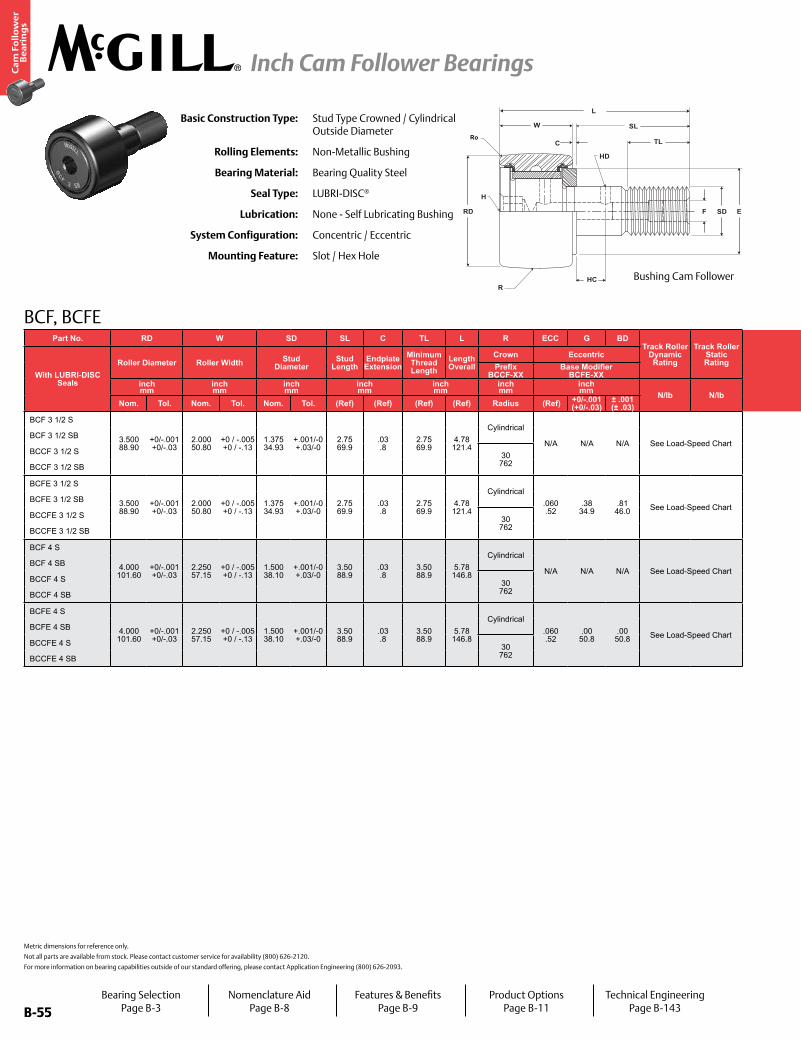
B-55
Ca
m F
oll
ow
er
Be
ari
ng
s
Inch Cam Follower Bearings
B-55
Part No. RD W SD SL C TL L R ECC G BDTrack Roller
Dynamic Rating
Track Roller Static Rating
Part No. HC HD F H E Ro
Housing Bore Diameter Thread
Type
Clamping Torque
Limiting Speed
WT
With LUBRI-DISC Seals
Roller Diameter Roller Width Stud Diameter
Stud Length
Endplate Extension
Minimum Thread Length
Length Overall
Crown Eccentric
With LUBRI-DISC Seals
Hole Center
Radial Hole Diameter
Axial Hole Dia
or FittingHex Hole Min Boss
DiameterOuter
Corner Radius
Bearing WeightPrefix
BCCF-XX Base Modifier
BCFE-XXinch mm
inch mm
inch mm
inch mm
inch mm
inch mm
inch mm N/lb N/lb
inch mm
inch mm
inch mm
inch mm in-lb
Nm RPM lbkgNom. Tol. Nom. Tol. Nom. Tol. (Ref) (Ref) (Ref) (Ref) Radius (Ref) +0/-.001
(+0/-.03)± .001 (± .03) (Ref) (Ref) (Ref) (Ref) (Ref) (Ref) Nom. Tol.
BCF 3 1/2 S
3.500 88.90
+0/-.001 +0/-.03
2.000 50.80
+0 / -.005 +0 / -.13
1.375 34.93
+.001/-0 +.03/-0
2.75 69.9
.03 .8
2.75 69.9
4.78 121.4
Cylindrical
N/A N/A N/A See Load-Speed Chart
BCF 3 1/2 S
.69 17.5
.125 3
.25 6.4
.75 19.1
2.44 61.9
.13 3.2
1.3753 34.933
+.0002/-.0003 +.0005/-.0008 1 3/8-12 4,200
475See Load-
Speed Chart6.42 2.91
BCF 3 1/2 SB BCF 3 1/2 SB
BCCF 3 1/2 S 30 762
BCCF 3 1/2 SN/A
BCCF 3 1/2 SB BCCF 3 1/2 SB
BCFE 3 1/2 S
3.500 88.90
+0/-.001 +0/-.03
2.000 50.80
+0 / -.005 +0 / -.13
1.375 34.93
+.001/-0 +.03/-0
2.75 69.9
.03 .8
2.75 69.9
4.78 121.4
Cylindrical.060 .52
.38 34.9
.81 46.0 See Load-Speed Chart
BCFE 3 1/2 S
.69 17.5
.125 3
.25 6.4
.75 19.1
2.44 61.9
.13 3.2
1.815 46.10
+.001/-.001 +.025/-.025 1 3/8-12 4,200
475See Load-
Speed Chart6.42 2.91
BCFE 3 1/2 SB BCFE 3 1/2 SB
BCCFE 3 1/2 S 30 762
BCCFE 3 1/2 SN/A
BCCFE 3 1/2 SB BCCFE 3 1/2 SB
BCF 4 S
4.000 101.60
+0/-.001 +0/-.03
2.250 57.15
+0 / -.005 +0 / -.13
1.500 38.10
+.001/-0 +.03/-0
3.50 88.9
.03 .8
3.50 88.9
5.78 146.8
Cylindrical
N/A N/A N/A See Load-Speed Chart
BCF 4 S
.75 19.1
.125 3
.25 6.4
.75 19.1
2.80 71.0
.13 3.2
1.5003 38.108
+.0002/-.0003 +.0005/-.0008 1 1/2-12 5,000
565See Load-
Speed Chart9.46 4.29
BCF 4 SB BCF 4 SB
BCCF 4 S 30 762
BCCF 4 SN/A
BCCF 4 SB BCCF 4 SB
BCFE 4 S
4.000 101.60
+0/-.001 +0/-.03
2.250 57.15
+0 / -.005 +0 / -.13
1.500 38.10
+.001/-0 +.03/-0
3.50 88.9
.03 .8
3.50 88.9
5.78 146.8
Cylindrical.060 .52
.00 50.8
.00 50.8 See Load-Speed Chart
BCFE 4 S
.75 19.1
.125 3
.25 6.4
.75 19.1
2.80 71.0
.13 3.2
2.003 50.85
+.001/-.001 +.025/-.025 1 1/2-12 5,000
565See Load-
Speed Chart9.46 4.29
BCFE 4 SB BCFE 4 SB
BCCFE 4 S 30 762
BCCFE 4 SN/A
BCCFE 4 SB BCCFE 4 SB
Metric dimensions for reference only.
Not all parts are available from stock. Please contact customer service for availability (800) 626-2120.
For more information on bearing capabilities outside of our standard offering, please contact Application Engineering (800) 626-2093.
BCF, BCFE
Basic Construction Type: Stud Type Crowned / Cylindrical Outside Diameter
Rolling Elements: Non-Metallic Bushing
Bearing Material: Bearing Quality Steel
Seal Type: LUBRI-DISC®
Lubrication: None - Self Lubricating Bushing
System Configuration: Concentric / Eccentric
Mounting Feature: Slot / Hex Hole
RD
W
C
SL
TL
HD
H
HC
F SD E
R
Ro
L
Bushing Cam Follower
Bearing SelectionPage B-3
Nomenclature AidPage B-8
Features & BenefitsPage B-9
Product OptionsPage B-11
Technical EngineeringPage B-143
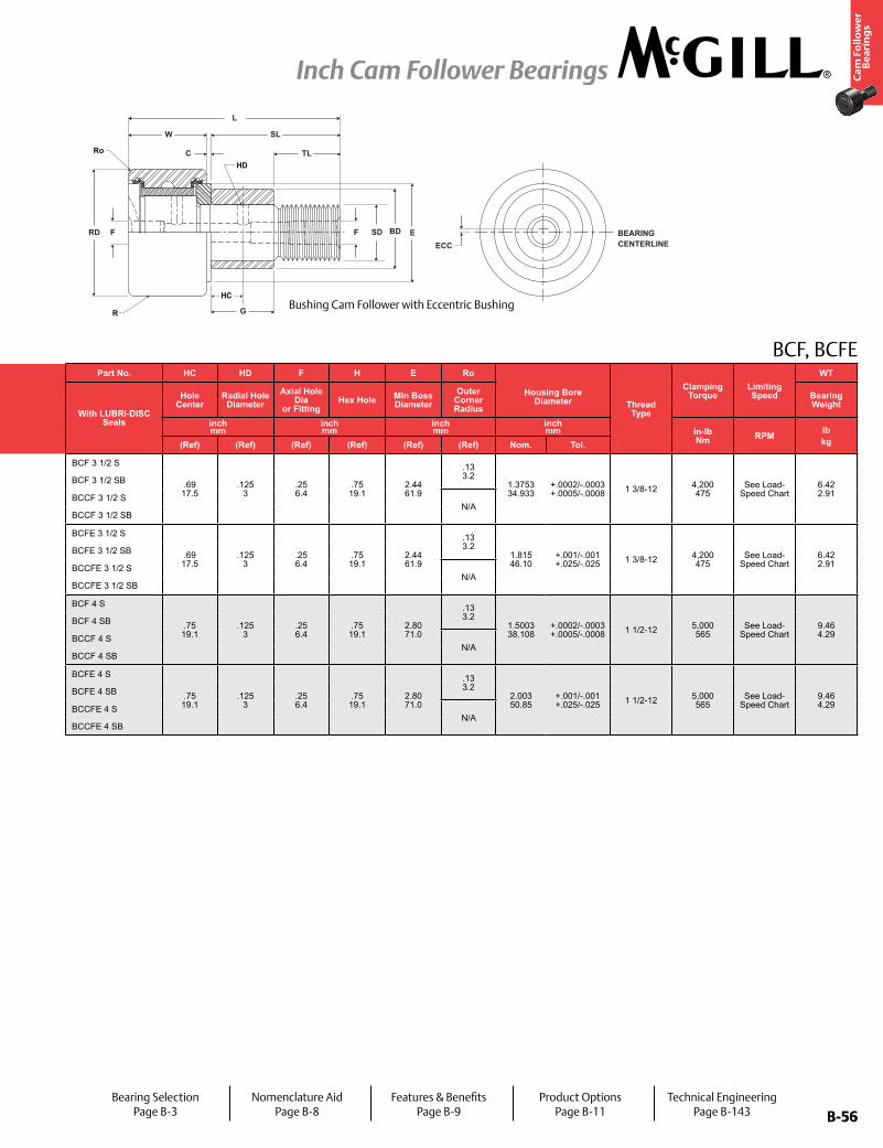
B-56
Ca
m F
oll
ow
er
Be
ari
ng
s
Inch Cam Follower Bearings
B-56
Part No. RD W SD SL C TL L R ECC G BDTrack Roller
Dynamic Rating
Track Roller Static Rating
Part No. HC HD F H E Ro
Housing Bore Diameter Thread
Type
Clamping Torque
Limiting Speed
WT
With LUBRI-DISC Seals
Roller Diameter Roller Width Stud Diameter
Stud Length
Endplate Extension
Minimum Thread Length
Length Overall
Crown Eccentric
With LUBRI-DISC Seals
Hole Center
Radial Hole Diameter
Axial Hole Dia
or FittingHex Hole Min Boss
DiameterOuter
Corner Radius
Bearing WeightPrefix
BCCF-XX Base Modifier
BCFE-XXinch mm
inch mm
inch mm
inch mm
inch mm
inch mm
inch mm N/lb N/lb
inch mm
inch mm
inch mm
inch mm in-lb
Nm RPM lbkgNom. Tol. Nom. Tol. Nom. Tol. (Ref) (Ref) (Ref) (Ref) Radius (Ref) +0/-.001
(+0/-.03)± .001 (± .03) (Ref) (Ref) (Ref) (Ref) (Ref) (Ref) Nom. Tol.
BCF 3 1/2 S
3.500 88.90
+0/-.001 +0/-.03
2.000 50.80
+0 / -.005 +0 / -.13
1.375 34.93
+.001/-0 +.03/-0
2.75 69.9
.03 .8
2.75 69.9
4.78 121.4
Cylindrical
N/A N/A N/A See Load-Speed Chart
BCF 3 1/2 S
.69 17.5
.125 3
.25 6.4
.75 19.1
2.44 61.9
.13 3.2
1.3753 34.933
+.0002/-.0003 +.0005/-.0008 1 3/8-12 4,200
475See Load-
Speed Chart6.42 2.91
BCF 3 1/2 SB BCF 3 1/2 SB
BCCF 3 1/2 S 30 762
BCCF 3 1/2 SN/A
BCCF 3 1/2 SB BCCF 3 1/2 SB
BCFE 3 1/2 S
3.500 88.90
+0/-.001 +0/-.03
2.000 50.80
+0 / -.005 +0 / -.13
1.375 34.93
+.001/-0 +.03/-0
2.75 69.9
.03 .8
2.75 69.9
4.78 121.4
Cylindrical.060 .52
.38 34.9
.81 46.0 See Load-Speed Chart
BCFE 3 1/2 S
.69 17.5
.125 3
.25 6.4
.75 19.1
2.44 61.9
.13 3.2
1.815 46.10
+.001/-.001 +.025/-.025 1 3/8-12 4,200
475See Load-
Speed Chart6.42 2.91
BCFE 3 1/2 SB BCFE 3 1/2 SB
BCCFE 3 1/2 S 30 762
BCCFE 3 1/2 SN/A
BCCFE 3 1/2 SB BCCFE 3 1/2 SB
BCF 4 S
4.000 101.60
+0/-.001 +0/-.03
2.250 57.15
+0 / -.005 +0 / -.13
1.500 38.10
+.001/-0 +.03/-0
3.50 88.9
.03 .8
3.50 88.9
5.78 146.8
Cylindrical
N/A N/A N/A See Load-Speed Chart
BCF 4 S
.75 19.1
.125 3
.25 6.4
.75 19.1
2.80 71.0
.13 3.2
1.5003 38.108
+.0002/-.0003 +.0005/-.0008 1 1/2-12 5,000
565See Load-
Speed Chart9.46 4.29
BCF 4 SB BCF 4 SB
BCCF 4 S 30 762
BCCF 4 SN/A
BCCF 4 SB BCCF 4 SB
BCFE 4 S
4.000 101.60
+0/-.001 +0/-.03
2.250 57.15
+0 / -.005 +0 / -.13
1.500 38.10
+.001/-0 +.03/-0
3.50 88.9
.03 .8
3.50 88.9
5.78 146.8
Cylindrical.060 .52
.00 50.8
.00 50.8 See Load-Speed Chart
BCFE 4 S
.75 19.1
.125 3
.25 6.4
.75 19.1
2.80 71.0
.13 3.2
2.003 50.85
+.001/-.001 +.025/-.025 1 1/2-12 5,000
565See Load-
Speed Chart9.46 4.29
BCFE 4 SB BCFE 4 SB
BCCFE 4 S 30 762
BCCFE 4 SN/A
BCCFE 4 SB BCCFE 4 SB
BCF, BCFE
FRD
C
W SL
TL
F BD E
G
BEARINGCENTERLINEECC
L
SD
R
Ro
HD
HC Bushing Cam Follower with Eccentric Bushing
Bearing SelectionPage B-3
Nomenclature AidPage B-8
Features & BenefitsPage B-9
Product OptionsPage B-11
Technical EngineeringPage B-143
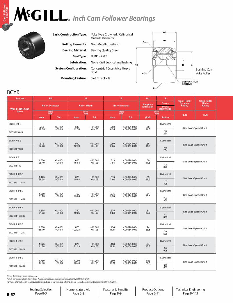
B-57
Ca
m F
oll
ow
er
Be
ari
ng
s
Inch Cam Follower Bearings
B-57
Basic Construction Type: Yoke Type Crowned / Cylindrical Outside Diameter
Rolling Elements: Non-Metallic Bushing
Bearing Material: Bearing Quality Steel
Seal Type: LUBRI-DISC®
Lubrication: None - Self Lubricating Bushing
System Configuration: Concentric / Eccentric / Heavy Stud
Mounting Feature: Slot / Hex Hole
BCYR
Metric dimensions for reference only.
Not all parts are available from stock. Please contact customer service for availability (800) 626-2120.
For more information on bearing capabilities outside of our standard offering, please contact Application Engineering (800) 626-2093.
R
HD
LUBRICATIONGROOVE
EBRD
W
W1
Ro
Part No. RD W B W1 RTrack Roller
Dynamic Rating
Track Roller Static Rating
Part No. HC E Ro PF PFT PF PFT PF PFTLimiting Speed
WT
With LUBRI-DISC Seals
Roller Diameter Roller Width Bore Diameter Endplate Extension
Crown
With LUBRI-DISC Seals
Hole Center
Min Boss Diameter
Outer Corner
Recommended Shaft Diameters Bearing WeightPrefix
BCCYR-XX Push Fit Drive Fit Press Fitinch mm
inch mm
inch mm
inch mm lb/N lb/N
inch mm
inch mm
inch mm
inch mm
inch mm RPM lb
kgNom. Tol. Nom. Tol. Nom Tol (Ref) Radius (Ref) (Ref) (Ref) Nom Tol Nom Tol Nom Tol
BCYR 3/4 S.750 19.05
+0/-.001 +0/-.03
.500 12.70
+0/-.001 +0/-.03
.250 6.35
+.0002/-.0004 +.0005/-.0010
.56 14.3
Cylindrical
See Load-Speed Chart
BCYR 3/4 S.25 6.4
.61 15.5
.02 .4
.2495 6.337
±.0002 ±.005
.2495 6.337
±.0002 ±.005
.2495 6.337
±.0002 ±.005
See Load-Speed Chart
.06
.03BCCYR 3/4 S 10
254 BCCYR 3/4 S N/A
BCYR 7/8 S.875 22.23
+0/-.001 +0/-.03
.500 12.70
+0/-.001 +0/-.03
.250 6.35
+.0002/-.0004 +.0005/-.0010
.56 14.3
Cylindrical
See Load-Speed Chart
BCYR 7/8 S.25 6.4
.61 15.5
.02 .4
.2495 6.337
±.0002 ±.005
.2495 6.337
±.0002 ±.005
.2495 6.337
±.0002 ±.005
See Load-Speed Chart
.08
.04BCCYR 7/8 S 10
254 BCCYR 7/8 S N/A
BCYR 1 S1.000 25.40
+0/-.001 +0/-.03
.625 15.88
+0/-.001 +0/-.03
.313 7.94
+.0002/-.0004 +.0005/-.0010
.69 17.5
Cylindrical
See Load-Speed Chart
BCYR 1 S.25 6.4
.78 19.8
.03 .8
.3120 7.925
±.0002 ±.005
.3120 7.925
±.0002 ±.005
.3120 7.925
±.0002 ±.005
See Load-Speed Chart
.15
.07BCCYR 1 S 12
305 BCCYR 1 S N/A
BCYR 1 1/8 S1.125 28.58
+0/-.001 +0/-.03
.625 15.88
+0/-.001 +0/-.03
.313 7.94
+.0002/-.0004 +.0005/-.0010
.69 17.5
Cylindrical
See Load-Speed Chart
BCYR 1 1/8 S.25 6.4
.78 19.8
.03 .8
.3120 7.925
±.0002 ±.005
.3120 7.925
±.0002 ±.005
.3120 7.925
±.0002 ±.005
See Load-Speed Chart
.17
.08BCCYR 1 1/8 S 12
305 BCCYR 1 1/8 S N/A
BCYR 1 1/4 S1.250 31.75
+0/-.001 +0/-.03
.750 19.05
+0/-.001 +0/-.03
.375 9.53
+.0002/-.0004 +.0005/-.0010
.81 20.6
Cylindrical
See Load-Speed Chart
BCYR 1 1/4 S.31 7.9
.98 25.0
.03 .8
.3745 9.512
±.0002 ±.005
.3745 9.512
±.0002 ±.005
.3745 9.512
±.0002 ±.005
See Load-Speed Chart
.24
.11BCCYR 1 1/4 S 14
356 BCCYR 1 1/4 S N/A
BCYR 1 3/8 S1.375 34.93
+0/-.001 +0/-.03
.750 19.05
+0/-.001 +0/-.03
.375 9.53
+.0002/-.0004 +.0005/-.0010
.81 20.6
Cylindrical
See Load-Speed Chart
BCYR 1 3/8 S.31 7.9
.98 25.0
.05 1.2
.3745 9.512
±.0002 ±.005
.3745 9.512
±.0002 ±.005
.3745 9.512
±.0002 ±.005
See Load-Speed Chart
.30
.14BCCYR 1 3/8 S 14
356 BCCYR 1 3/8 S N/A
BCYR 1 1/2 S1.500 38.10
+0/-.001 +0/-.03
.875 22.23
+0/-.001 +0/-.03
.438 11.11
+.0002/-.0004 +.0005/-.0010
.94 23.8
Cylindrical
See Load-Speed Chart
BCYR 1 1/2 S.38 9.5
1.09 27.8
.06 1.6
.4370 11.100
±.0002 ±.005
.4370 11.100
±.0002 ±.005
.4370 11.100
±.0002 ±.005
See Load-Speed Chart
.41
.19BCCYR 1 1/2 S 20
508 BCCYR 1 1/2 S N/A
BCYR 1 5/8 S1.625 41.28
+0/-.001 +0/-.03
.875 22.23
+0/-.001 +0/-.03
.438 11.11
+.0002/-.0004 +.0005/-.0010
.94 23.8
Cylindrical
See Load-Speed Chart
BCYR 1 5/8 S.38 9.5
1.09 27.8
.06 1.6
.4370 11.100
±.0002 ±.005
.4370 11.100
±.0002 ±.005
.4370 11.100
±.0002 ±.005
See Load-Speed Chart
.50
.23BCCYR 1 5/8 S 20
508 BCCYR 1 5/8 S N/A
BCYR 1 3/4 S1.750 44.45
+0/-.001 +0/-.03
1.000 25.40
+0/-.001 +0/-.03
.500 12.70
+.0002/-.0004 +.0005/-.0010
1.06 27.0
Cylindrical
See Load-Speed Chart
BCYR 1 3/4 S.44 11.1
1.25 31.8
.06 1.6
.4995 12.687
±.0002 ±.005
.4995 12.687
±.0002 ±.005
.4995 12.687
±.0002 ±.005
See Load-Speed Chart
.64
.29BCCYR 1 3/4 S 20
508 BCCYR 1 3/4 S N/A
Bushing Cam Yoke Roller
Bearing SelectionPage B-3
Nomenclature AidPage B-8
Features & BenefitsPage B-9
Product OptionsPage B-11
Technical EngineeringPage B-143

B-58
Ca
m F
oll
ow
er
Be
ari
ng
s
Inch Cam Follower Bearings
B-58
BCYRPart No. RD W B W1 R
Track Roller Dynamic Rating
Track Roller Static Rating
Part No. HC E Ro PF PFT PF PFT PF PFTLimiting Speed
WT
With LUBRI-DISC Seals
Roller Diameter Roller Width Bore Diameter Endplate Extension
Crown
With LUBRI-DISC Seals
Hole Center
Min Boss Diameter
Outer Corner
Recommended Shaft Diameters Bearing WeightPrefix
BCCYR-XX Push Fit Drive Fit Press Fitinch mm
inch mm
inch mm
inch mm lb/N lb/N
inch mm
inch mm
inch mm
inch mm
inch mm RPM lb
kgNom. Tol. Nom. Tol. Nom Tol (Ref) Radius (Ref) (Ref) (Ref) Nom Tol Nom Tol Nom Tol
BCYR 3/4 S.750 19.05
+0/-.001 +0/-.03
.500 12.70
+0/-.001 +0/-.03
.250 6.35
+.0002/-.0004 +.0005/-.0010
.56 14.3
Cylindrical
See Load-Speed Chart
BCYR 3/4 S.25 6.4
.61 15.5
.02 .4
.2495 6.337
±.0002 ±.005
.2495 6.337
±.0002 ±.005
.2495 6.337
±.0002 ±.005
See Load-Speed Chart
.06
.03BCCYR 3/4 S 10
254 BCCYR 3/4 S N/A
BCYR 7/8 S.875 22.23
+0/-.001 +0/-.03
.500 12.70
+0/-.001 +0/-.03
.250 6.35
+.0002/-.0004 +.0005/-.0010
.56 14.3
Cylindrical
See Load-Speed Chart
BCYR 7/8 S.25 6.4
.61 15.5
.02 .4
.2495 6.337
±.0002 ±.005
.2495 6.337
±.0002 ±.005
.2495 6.337
±.0002 ±.005
See Load-Speed Chart
.08
.04BCCYR 7/8 S 10
254 BCCYR 7/8 S N/A
BCYR 1 S1.000 25.40
+0/-.001 +0/-.03
.625 15.88
+0/-.001 +0/-.03
.313 7.94
+.0002/-.0004 +.0005/-.0010
.69 17.5
Cylindrical
See Load-Speed Chart
BCYR 1 S.25 6.4
.78 19.8
.03 .8
.3120 7.925
±.0002 ±.005
.3120 7.925
±.0002 ±.005
.3120 7.925
±.0002 ±.005
See Load-Speed Chart
.15
.07BCCYR 1 S 12
305 BCCYR 1 S N/A
BCYR 1 1/8 S1.125 28.58
+0/-.001 +0/-.03
.625 15.88
+0/-.001 +0/-.03
.313 7.94
+.0002/-.0004 +.0005/-.0010
.69 17.5
Cylindrical
See Load-Speed Chart
BCYR 1 1/8 S.25 6.4
.78 19.8
.03 .8
.3120 7.925
±.0002 ±.005
.3120 7.925
±.0002 ±.005
.3120 7.925
±.0002 ±.005
See Load-Speed Chart
.17
.08BCCYR 1 1/8 S 12
305 BCCYR 1 1/8 S N/A
BCYR 1 1/4 S1.250 31.75
+0/-.001 +0/-.03
.750 19.05
+0/-.001 +0/-.03
.375 9.53
+.0002/-.0004 +.0005/-.0010
.81 20.6
Cylindrical
See Load-Speed Chart
BCYR 1 1/4 S.31 7.9
.98 25.0
.03 .8
.3745 9.512
±.0002 ±.005
.3745 9.512
±.0002 ±.005
.3745 9.512
±.0002 ±.005
See Load-Speed Chart
.24
.11BCCYR 1 1/4 S 14
356 BCCYR 1 1/4 S N/A
BCYR 1 3/8 S1.375 34.93
+0/-.001 +0/-.03
.750 19.05
+0/-.001 +0/-.03
.375 9.53
+.0002/-.0004 +.0005/-.0010
.81 20.6
Cylindrical
See Load-Speed Chart
BCYR 1 3/8 S.31 7.9
.98 25.0
.05 1.2
.3745 9.512
±.0002 ±.005
.3745 9.512
±.0002 ±.005
.3745 9.512
±.0002 ±.005
See Load-Speed Chart
.30
.14BCCYR 1 3/8 S 14
356 BCCYR 1 3/8 S N/A
BCYR 1 1/2 S1.500 38.10
+0/-.001 +0/-.03
.875 22.23
+0/-.001 +0/-.03
.438 11.11
+.0002/-.0004 +.0005/-.0010
.94 23.8
Cylindrical
See Load-Speed Chart
BCYR 1 1/2 S.38 9.5
1.09 27.8
.06 1.6
.4370 11.100
±.0002 ±.005
.4370 11.100
±.0002 ±.005
.4370 11.100
±.0002 ±.005
See Load-Speed Chart
.41
.19BCCYR 1 1/2 S 20
508 BCCYR 1 1/2 S N/A
BCYR 1 5/8 S1.625 41.28
+0/-.001 +0/-.03
.875 22.23
+0/-.001 +0/-.03
.438 11.11
+.0002/-.0004 +.0005/-.0010
.94 23.8
Cylindrical
See Load-Speed Chart
BCYR 1 5/8 S.38 9.5
1.09 27.8
.06 1.6
.4370 11.100
±.0002 ±.005
.4370 11.100
±.0002 ±.005
.4370 11.100
±.0002 ±.005
See Load-Speed Chart
.50
.23BCCYR 1 5/8 S 20
508 BCCYR 1 5/8 S N/A
BCYR 1 3/4 S1.750 44.45
+0/-.001 +0/-.03
1.000 25.40
+0/-.001 +0/-.03
.500 12.70
+.0002/-.0004 +.0005/-.0010
1.06 27.0
Cylindrical
See Load-Speed Chart
BCYR 1 3/4 S.44 11.1
1.25 31.8
.06 1.6
.4995 12.687
±.0002 ±.005
.4995 12.687
±.0002 ±.005
.4995 12.687
±.0002 ±.005
See Load-Speed Chart
.64
.29BCCYR 1 3/4 S 20
508 BCCYR 1 3/4 S N/A
Bearing SelectionPage B-3
Nomenclature AidPage B-8
Features & BenefitsPage B-9
Product OptionsPage B-11
Technical EngineeringPage B-143
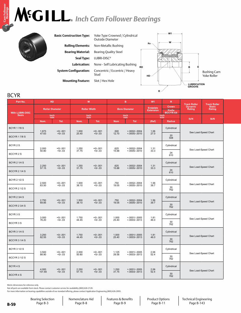
B-59
Ca
m F
oll
ow
er
Be
ari
ng
s
Inch Cam Follower Bearings
B-59
Part No. RD W B W1 RTrack Roller
Dynamic Rating
Track Roller Static Rating
Part No. HC E Ro PF PFT PF PFT PF PFTLimiting Speed
WT
With LUBRI-DISC Seals
Roller Diameter Roller Width Bore Diameter Endplate Extension
Crown
With LUBRI-DISC Seals
Hole Center
Min Boss Diameter
Outer Corner
Recommended Shaft Diameters Bearing WeightPrefix
BCCYR-XX Push Fit Drive Fit Press Fitinch mm
inch mm
inch mm
inch mm lb/N lb/N
inch mm
inch mm
inch mm
inch mm
inch mm RPM lb
kgNom. Tol. Nom. Tol. Nom Tol (Ref) Radius (Ref) (Ref) (Ref) Nom Tol Nom Tol Nom Tol
BCYR 1 7/8 S1.875 47.63
+0/-.001 +0/-.03
1.000 25.40
+0/-.001 +0/-.03
.500 12.70
+.0002/-.0004 +.0005/-.0010
1.06 27.0
Cylindrical
See Load-Speed Chart
BCYR 1 7/8 S.44 11.1
1.25 31.8
.06 1.6
.4995 12.687
±.0002 ±.005
.4995 12.687
±.0002 ±.005
.4995 12.687
±.0002 ±.005
See Load-Speed Chart
.80
.36BCCYR 1 7/8 S 20
508 BCCYR 1 7/8 S N/A
BCYR 2 S2.000 50.80
+0/-.001 +0/-.03
1.250 31.75
+0/-.001 +0/-.03
.625 15.88
+.0002/-.0004 +.0005/-.0010
1.31 33.3
Cylindrical
See Load-Speed Chart
BCYR 2 S.50
12.71.41 35.7
.09 2.4
.6245 15.862
±.0002 ±.005
.6245 15.862
±.0002 ±.005
.6245 15.862
±.0002 ±.005
See Load-Speed Chart
1.05 .48
BCCYR 2 S 24 610 BCCYR 2 S N/A
BCYR 2 1/4 S2.250 57.15
+0/-.001 +0/-.03
1.250 31.75
+0/-.001 +0/-.03
.625 15.88
+.0002/-.0004 +.0005/-.0010
1.31 33.3
Cylindrical
See Load-Speed Chart
BCYR 2 1/4 S.50
12.71.41 35.7
.09 2.4
.6245 15.862
±.0002 ±.005
.6245 15.862
±.0002 ±.005
.6245 15.862
±.0002 ±.005
See Load-Speed Chart
1.32 .59
BCCYR 2 1/4 S 24 610 BCCYR 2 1/4 S N/A
BCYR 2 1/2 S2.500 63.50
+0/-.001 +0/-.03
1.500 38.10
+0/-.001 +0/-.03
.750 19.05
+.0002/-.0004 +.0005/-.0010
1.56 39.7
Cylindrical
See Load-Speed Chart
BCYR 2 1/2 S.56
14.31.69 42.9
.09 2.4
.7495 19.037
±.0002 ±.005
.7495 19.037
±.0002 ±.005
.7495 19.037
±.0002 ±.005
See Load-Speed Chart
1.80 .82
BCCYR 2 1/2 S 30 762 BCCYR 2 1/2 S N/A
BCYR 2 3/4 S2.750 69.85
+0/-.001 +0/-.03
1.500 38.10
+0/-.001 +0/-.03
.750 19.05
+.0002/-.0004 +.0005/-.0010
1.56 39.7
Cylindrical
See Load-Speed Chart
BCYR 2 3/4 S.56
14.31.69 42.9
.09 2.4
.7495 19.037
±.0002 ±.005
.7495 19.037
±.0002 ±.005
.7495 19.037
±.0002 ±.005
See Load-Speed Chart
2.25 1.02
BCCYR 2 3/4 S 30 762 BCCYR 2 3/4 S N/A
BCYR 3 S3.000 76.20
+0/-.001 +0/-.03
1.750 44.45
+0/-.001 +0/-.03
1.000 25.40
+.0001/-.0005 +.0003/-.0013
1.81 46.0
Cylindrical
See Load-Speed Chart
BCYR 3 S.63
15.92.13 54.0
.13 3.2
.9994 25.385
±.0002 ±.005
.9994 25.385
±.0002 ±.005
.9994 25.385
±.0002 ±.005
See Load-Speed Chart
3.10 1.41
BCCYR 3 S 30 762 BCCYR 3 S N/A
BCYR 3 1/4 S3.250 82.55
+0/-.001 +0/-.03
1.750 44.45
+0/-.001 +0/-.03
1.000 25.40
+.0001/-.0005 +.0003/-.0013
1.81 46.0
Cylindrical
See Load-Speed Chart
BCYR 3 1/4 S.63
15.92.13 54.0
.13 3.2
.9994 25.385
±.0002 ±.005
.9994 25.385
±.0002 ±.005
.9994 25.385
±.0002 ±.005
See Load-Speed Chart
3.62 1.64
BCCYR 3 1/4 S 30 762 BCCYR 3 1/4 S N/A
BCYR 3 1/2 S3.500 88.90
+0/-.001 +0/-.03
2.000 50.80
+0/-.001 +0/-.03
1.125 28.58
+.0001/-.0005 +.0003/-.0013
2.06 52.4
Cylindrical
See Load-Speed Chart
BCYR 3 1/2 S.69
17.52.44 61.9
.13 3.2
1.1244 28.560
±.0002 ±.005
1.1244 28.560
±.0002 ±.005
1.1244 28.560
±.0002 ±.005
See Load-Speed Chart
4.95 2.25
BCCYR 3 1/2 S 30 762 BCCYR 3 1/2 S N/A
BCYR 4 S4.000 101.60
+0/-.001 +0/-.03
2.250 57.15
+0/-.001 +0/-.03
1.250 31.75
+.0001/-.0005 +.0003/-.0013
2.06 52.4
Cylindrical
See Load-Speed Chart
BCYR 4 S.75
19.12.80 71.0
.13 3.2
1.2494 31.735
±.0002 ±.005
1.2494 31.735
±.0002 ±.005
1.2494 31.735
±.0002 ±.005
See Load-Speed Chart
7.05 3.19
BCCYR 4 S 30 762 BCCYR 4 S N/A
Basic Construction Type: Yoke Type Crowned / Cylindrical Outside Diameter
Rolling Elements: Non-Metallic Bushing
Bearing Material: Bearing Quality Steel
Seal Type: LUBRI-DISC®
Lubrication: None - Self Lubricating Bushing
System Configuration: Concentric / Eccentric / Heavy Stud
Mounting Feature: Slot / Hex Hole
BCYR
Metric dimensions for reference only.
Not all parts are available from stock. Please contact customer service for availability (800) 626-2120.
For more information on bearing capabilities outside of our standard offering, please contact Application Engineering (800) 626-2093.
R
HD
LUBRICATIONGROOVE
EBRD
W
W1
Ro
Bushing Cam Yoke Roller
Bearing SelectionPage B-3
Nomenclature AidPage B-8
Features & BenefitsPage B-9
Product OptionsPage B-11
Technical EngineeringPage B-143
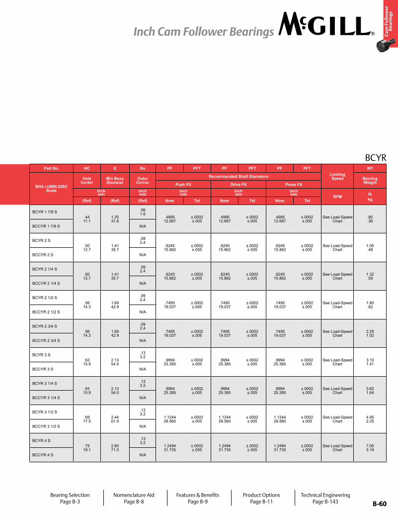
B-60
Ca
m F
oll
ow
er
Be
ari
ng
s
Inch Cam Follower Bearings
B-60
Part No. RD W B W1 RTrack Roller
Dynamic Rating
Track Roller Static Rating
Part No. HC E Ro PF PFT PF PFT PF PFTLimiting Speed
WT
With LUBRI-DISC Seals
Roller Diameter Roller Width Bore Diameter Endplate Extension
Crown
With LUBRI-DISC Seals
Hole Center
Min Boss Diameter
Outer Corner
Recommended Shaft Diameters Bearing WeightPrefix
BCCYR-XX Push Fit Drive Fit Press Fitinch mm
inch mm
inch mm
inch mm lb/N lb/N
inch mm
inch mm
inch mm
inch mm
inch mm RPM lb
kgNom. Tol. Nom. Tol. Nom Tol (Ref) Radius (Ref) (Ref) (Ref) Nom Tol Nom Tol Nom Tol
BCYR 1 7/8 S1.875 47.63
+0/-.001 +0/-.03
1.000 25.40
+0/-.001 +0/-.03
.500 12.70
+.0002/-.0004 +.0005/-.0010
1.06 27.0
Cylindrical
See Load-Speed Chart
BCYR 1 7/8 S.44 11.1
1.25 31.8
.06 1.6
.4995 12.687
±.0002 ±.005
.4995 12.687
±.0002 ±.005
.4995 12.687
±.0002 ±.005
See Load-Speed Chart
.80
.36BCCYR 1 7/8 S 20
508 BCCYR 1 7/8 S N/A
BCYR 2 S2.000 50.80
+0/-.001 +0/-.03
1.250 31.75
+0/-.001 +0/-.03
.625 15.88
+.0002/-.0004 +.0005/-.0010
1.31 33.3
Cylindrical
See Load-Speed Chart
BCYR 2 S.50 12.7
1.41 35.7
.09 2.4
.6245 15.862
±.0002 ±.005
.6245 15.862
±.0002 ±.005
.6245 15.862
±.0002 ±.005
See Load-Speed Chart
1.05 .48
BCCYR 2 S 24 610 BCCYR 2 S N/A
BCYR 2 1/4 S2.250 57.15
+0/-.001 +0/-.03
1.250 31.75
+0/-.001 +0/-.03
.625 15.88
+.0002/-.0004 +.0005/-.0010
1.31 33.3
Cylindrical
See Load-Speed Chart
BCYR 2 1/4 S.50 12.7
1.41 35.7
.09 2.4
.6245 15.862
±.0002 ±.005
.6245 15.862
±.0002 ±.005
.6245 15.862
±.0002 ±.005
See Load-Speed Chart
1.32 .59
BCCYR 2 1/4 S 24 610 BCCYR 2 1/4 S N/A
BCYR 2 1/2 S2.500 63.50
+0/-.001 +0/-.03
1.500 38.10
+0/-.001 +0/-.03
.750 19.05
+.0002/-.0004 +.0005/-.0010
1.56 39.7
Cylindrical
See Load-Speed Chart
BCYR 2 1/2 S.56 14.3
1.69 42.9
.09 2.4
.7495 19.037
±.0002 ±.005
.7495 19.037
±.0002 ±.005
.7495 19.037
±.0002 ±.005
See Load-Speed Chart
1.80 .82
BCCYR 2 1/2 S 30 762 BCCYR 2 1/2 S N/A
BCYR 2 3/4 S2.750 69.85
+0/-.001 +0/-.03
1.500 38.10
+0/-.001 +0/-.03
.750 19.05
+.0002/-.0004 +.0005/-.0010
1.56 39.7
Cylindrical
See Load-Speed Chart
BCYR 2 3/4 S.56 14.3
1.69 42.9
.09 2.4
.7495 19.037
±.0002 ±.005
.7495 19.037
±.0002 ±.005
.7495 19.037
±.0002 ±.005
See Load-Speed Chart
2.25 1.02
BCCYR 2 3/4 S 30 762 BCCYR 2 3/4 S N/A
BCYR 3 S3.000 76.20
+0/-.001 +0/-.03
1.750 44.45
+0/-.001 +0/-.03
1.000 25.40
+.0001/-.0005 +.0003/-.0013
1.81 46.0
Cylindrical
See Load-Speed Chart
BCYR 3 S.63 15.9
2.13 54.0
.13 3.2
.9994 25.385
±.0002 ±.005
.9994 25.385
±.0002 ±.005
.9994 25.385
±.0002 ±.005
See Load-Speed Chart
3.10 1.41
BCCYR 3 S 30 762 BCCYR 3 S N/A
BCYR 3 1/4 S3.250 82.55
+0/-.001 +0/-.03
1.750 44.45
+0/-.001 +0/-.03
1.000 25.40
+.0001/-.0005 +.0003/-.0013
1.81 46.0
Cylindrical
See Load-Speed Chart
BCYR 3 1/4 S.63 15.9
2.13 54.0
.13 3.2
.9994 25.385
±.0002 ±.005
.9994 25.385
±.0002 ±.005
.9994 25.385
±.0002 ±.005
See Load-Speed Chart
3.62 1.64
BCCYR 3 1/4 S 30 762 BCCYR 3 1/4 S N/A
BCYR 3 1/2 S3.500 88.90
+0/-.001 +0/-.03
2.000 50.80
+0/-.001 +0/-.03
1.125 28.58
+.0001/-.0005 +.0003/-.0013
2.06 52.4
Cylindrical
See Load-Speed Chart
BCYR 3 1/2 S.69 17.5
2.44 61.9
.13 3.2
1.1244 28.560
±.0002 ±.005
1.1244 28.560
±.0002 ±.005
1.1244 28.560
±.0002 ±.005
See Load-Speed Chart
4.95 2.25
BCCYR 3 1/2 S 30 762 BCCYR 3 1/2 S N/A
BCYR 4 S4.000 101.60
+0/-.001 +0/-.03
2.250 57.15
+0/-.001 +0/-.03
1.250 31.75
+.0001/-.0005 +.0003/-.0013
2.06 52.4
Cylindrical
See Load-Speed Chart
BCYR 4 S.75 19.1
2.80 71.0
.13 3.2
1.2494 31.735
±.0002 ±.005
1.2494 31.735
±.0002 ±.005
1.2494 31.735
±.0002 ±.005
See Load-Speed Chart
7.05 3.19
BCCYR 4 S 30 762 BCCYR 4 S N/A
BCYR
Bearing SelectionPage B-3
Nomenclature AidPage B-8
Features & BenefitsPage B-9
Product OptionsPage B-11
Technical EngineeringPage B-143
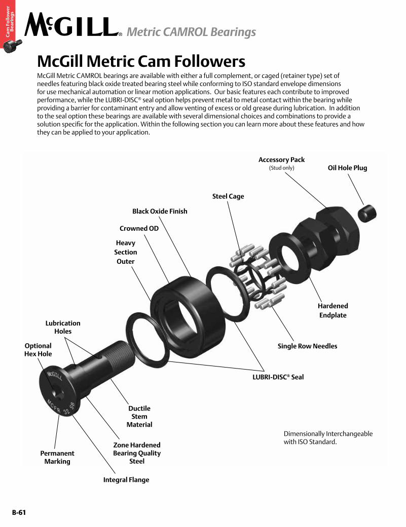
B-61
Ca
m F
oll
ow
er
Be
ari
ng
s
Metric CAMROL Bearings
B-61
McGill Metric Cam FollowersMcGill Metric CAMROL bearings are available with either a full complement, or caged (retainer type) set of needles featuring black oxide treated bearing steel while conforming to ISO standard envelope dimensions for use mechanical automation or linear motion applications. Our basic features each contribute to improved performance, while the LUBRI-DISC® seal option helps prevent metal to metal contact within the bearing while providing a barrier for contaminant entry and allow venting of excess or old grease during lubrication. In addition to the seal option these bearings are available with several dimensional choices and combinations to provide a solution specific for the application. Within the following section you can learn more about these features and how they can be applied to your application.
Accessory Pack(Stud only) Oil Hole Plug
HardenedEndplate
Single Row Needles
Ductile Stem
Material
Zone Hardened Bearing Quality
Steel
Integral Flange
Permanent Marking
LUBRI-DISC® Seal
Black Oxide Finish
Crowned OD
Heavy Section Outer
Lubrication Holes
Dimensionally Interchangeable with ISO Standard.
Steel Cage
Optional Hex Hole
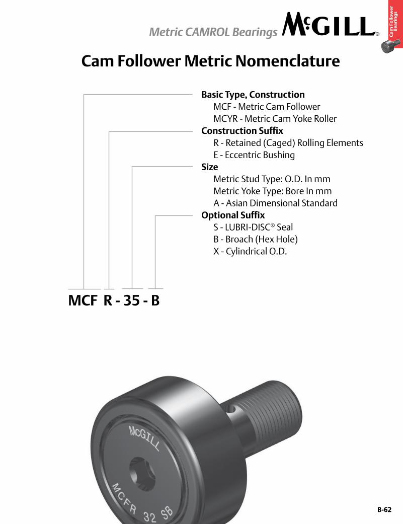
B-62
Ca
m F
oll
ow
er
Be
ari
ng
s
Metric CAMROL Bearings
B-62
Cam Follower Metric Nomenclature
Basic Type, Construction MCF - Metric Cam Follower MCYR - Metric Cam Yoke RollerConstruction Suffix R - Retained (Caged) Rolling Elements E - Eccentric BushingSize Metric Stud Type: O.D. In mm Metric Yoke Type: Bore In mm A - Asian Dimensional StandardOptional Suffix S - LUBRI-DISC® Seal B - Broach (Hex Hole) X - Cylindrical O.D.
MCF R - 35 - B
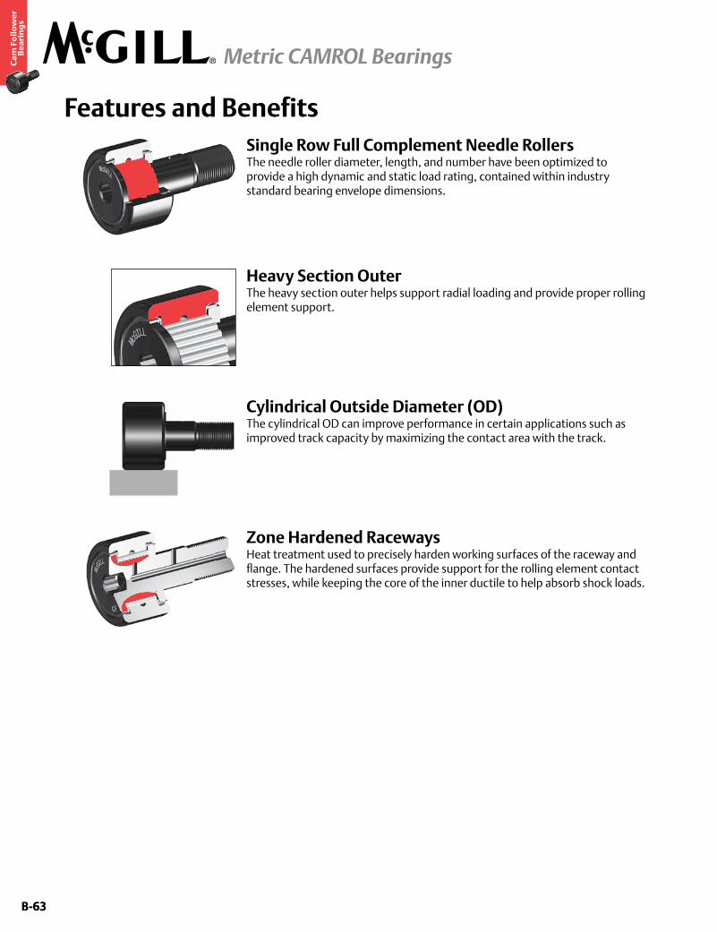
B-63
Ca
m F
oll
ow
er
Be
ari
ng
s
Metric CAMROL Bearings
B-63
Features and BenefitsSingle Row Full Complement Needle RollersThe needle roller diameter, length, and number have been optimized to provide a high dynamic and static load rating, contained within industry standard bearing envelope dimensions.
Cylindrical Outside Diameter (OD)The cylindrical OD can improve performance in certain applications such as improved track capacity by maximizing the contact area with the track.
Heavy Section OuterThe heavy section outer helps support radial loading and provide proper rolling element support.
Zone Hardened RacewaysHeat treatment used to precisely harden working surfaces of the raceway and flange. The hardened surfaces provide support for the rolling element contact stresses, while keeping the core of the inner ductile to help absorb shock loads.
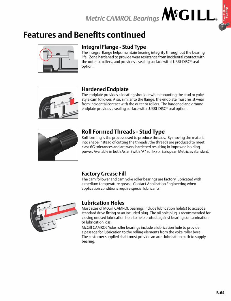
B-64
Ca
m F
oll
ow
er
Be
ari
ng
s
Metric CAMROL Bearings
B-64
Features and Benefits continued
Hardened EndplateThe endplate provides a locating shoulder when mounting the stud or yoke style cam follower. Also, similar to the flange, the endplate must resist wear from incidental contact with the outer or rollers. The hardened and ground endplate provides a sealing surface with LUBRI-DISC® seal option.
Factory Grease FillThe cam follower and cam yoke roller bearings are factory lubricated with a medium temperature grease. Contact Application Engineering when application conditions require special lubricants.
Roll Formed Threads - Stud TypeRoll forming is the process used to produce threads. By moving the material into shape instead of cutting the threads, the threads are produced to meet class 6G tolerances and are work hardened resulting in improved holding power. Available in both Asian (with “A” suffix) or European Metric as standard.
Lubrication HolesMost sizes of McGill CAMROL bearings include lubrication hole(s) to accept a standard drive fitting or an included plug. The oil hole plug is recommended for closing unused lubrication hole to help protect against bearing contamination or lubrication loss. McGill CAMROL Yoke roller bearings include a lubrication hole to provide a passage for lubrication to the rolling elements from the yoke roller bore. The customer supplied shaft must provide an axial lubrication path to supply bearing.
Integral Flange - Stud TypeThe integral flange helps maintain bearing integrity throughout the bearing life. Zone hardened to provide wear resistance from incidental contact with the outer or rollers, and provides a sealing surface with LUBRI-DISC® seal option.
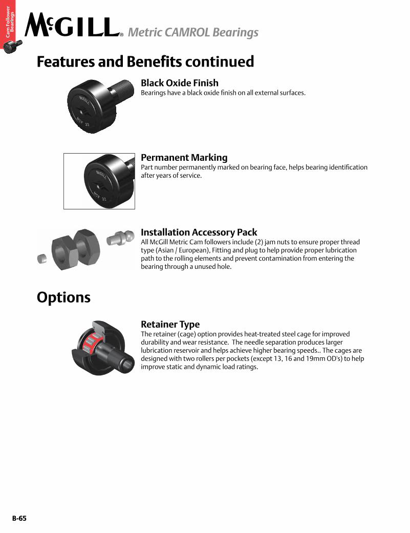
B-65
Ca
m F
oll
ow
er
Be
ari
ng
s
Metric CAMROL Bearings
B-65
Options
Features and Benefits continued
Installation Accessory PackAll McGill Metric Cam followers include (2) jam nuts to ensure proper thread type (Asian / European), Fitting and plug to help provide proper lubrication path to the rolling elements and prevent contamination from entering the bearing through a unused hole.
Permanent MarkingPart number permanently marked on bearing face, helps bearing identification after years of service.
Features and Benefits
Retainer TypeThe retainer (cage) option provides heat-treated steel cage for improved durability and wear resistance. The needle separation produces larger lubrication reservoir and helps achieve higher bearing speeds.. The cages are designed with two rollers per pockets (except 13, 16 and 19mm OD's) to help improve static and dynamic load ratings.
Black Oxide Finish Bearings have a black oxide finish on all external surfaces.
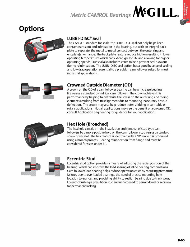
B-66
Ca
m F
oll
ow
er
Be
ari
ng
s
Metric CAMROL Bearings
B-66
Options
Crowned Outside Diameter (OD)A crown on the OD of a cam follower bearing can help increase bearing life versus a standard cylindrical cam follower. The crown achieves this performance by helping to distribute the stress on the outer ring and rolling elements resulting from misalignment due to mounting inaccuracy or stud deflection. The crown may also help reduce outer skidding in turntable or rotary applications. Not all applications may see the benefit of a crowned OD, consult Application Engineering for guidance for your application.
LUBRI-DISC® SealThe CAMROL standard for seals, the LUBRI-DISC seal not only helps keep contaminants out and lubrication in the bearing, but with an integral back plate to separate the metal to metal contact between the outer ring and endplate(s) or flange. The back plate feature reduce friction resulting in lower operating temperatures which can extend grease life and allowing for higher operating speeds Our seal also includes vents to help prevent seal blowout during relubrication. The LUBRI-DISC seal option has a good balance of sealing and low drag operation essential to a precision cam follower suited for most industrial applications.
Eccentric StudEccentric stud option provides a means of adjusting the radial position of the bearing, which can improve the load sharing of inline bearing combinations. Cam follower load sharing helps reduce operation costs by reducing premature failures due to overloaded bearings, the need of precise mounting hole location tolerances and providing ability to realign bearing due to track wear. Eccentric bushing is press fit on stud and unhardened to permit dowel or setscrew for permanent locking.
Hex Hole (Broached)The hex hole can aide in the installation and removal of stud type cam followers by a more positive hold on the cam follower stud versus a standard screw driver slot. The hex feature is identified with a “B” since it is produced using a broach process. Bearing relubrication from flange end must be considered for sizes under 3”.
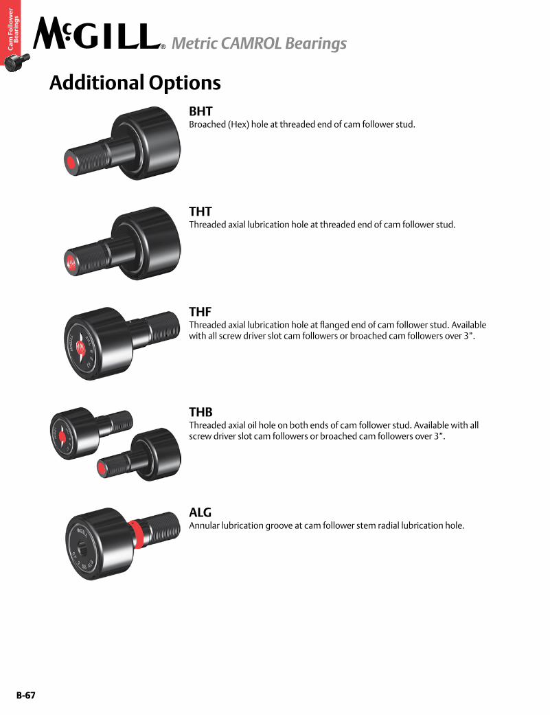
B-67
Ca
m F
oll
ow
er
Be
ari
ng
s
Metric CAMROL Bearings
B-67
Additional Options
THFThreaded axial lubrication hole at flanged end of cam follower stud. Available with all screw driver slot cam followers or broached cam followers over 3”.
THTThreaded axial lubrication hole at threaded end of cam follower stud.
THBThreaded axial oil hole on both ends of cam follower stud. Available with all screw driver slot cam followers or broached cam followers over 3”.
ALGAnnular lubrication groove at cam follower stem radial lubrication hole.
BHTBroached (Hex) hole at threaded end of cam follower stud.

B-68
Ca
m F
oll
ow
er
Be
ari
ng
s
Metric CAMROL Bearings
B-68
Custom Capabilities• Customerspecifiedfactorygreasefill
• Greasefittinginstalled
• Studorthreadlengthmodifications
• Rollerdiametervariationsortolerances
• Camfollowersgroupedormatcheddiametertolerance/runoutsets
• Customengineeredtoorderdesigns
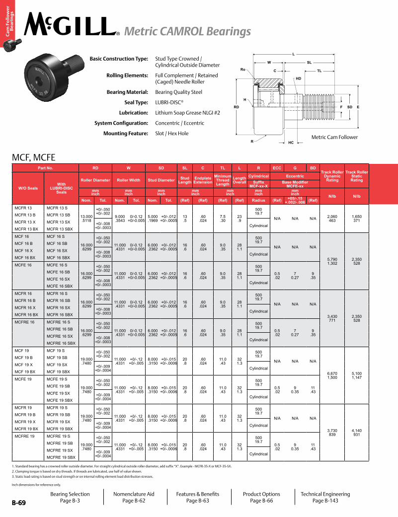
B-69
Ca
m F
oll
ow
er
Be
ari
ng
s
Metric CAMROL Bearings
B-69
Part No. RD W SD SL C TL L R ECC G BDTrack Roller
Dynamic Rating
Track Roller Static Rating
Part No. HC HD F H Ro E Housing Bore
DiameterThread Type
Clamping Torque
Limiting Speed
(Grease)
WT
W/O SealsWith
LUBRI-DISC Seals
Roller Diameter Roller Width Stud Diameter Stud Length
Endplate Extension
Minimum Thread Length
Length Overall
Cylindrical Eccentric
W/O SealsWith
LUBRI-DISC Seals
Hole Center
Radial Lub. Hole
DiameterLub. Hole
DiaHex Hole Outer
CornerMin.
Clamping Diameter
Bearing WeightSuffix
MCF-xx-XBase Modifier
MCFE-xxSuffix
MCF_xx Bmm inch
mm inch
mm inch
mm inch
mm inch
mm inch
mm inch N/lb N/lb
mm inch
mm inch
mm inch
mm inch Nm
in-lb RPM kglbNom. Tol. Nom. Tol. Nom. Tol. (Ref) (Ref) (Ref) (Ref) Radius (Ref) +05/-.15
+.002/-.006 (Ref) (Ref) (Ref) (Ref) (Ref) (Ref) (Ref) Nom. Tol.
MCFR 13 MCFR 13 S
13.000 .5118
+0/-.050 +0/-.002
9.000 .3543
0/-0.12 +0/-0.005
5.000 .1969
+0/-.012 +0/-.0005
13 .5
.60 .024
7.5 .30
23 .9
500 19.7
N/A N/A N/A 2,060 463
1,650 371
MCFR 13 MCFR 13 S
- -
3.1 .12 N/A
.3 .01
9 .4
5.000 .1969
+.012/-0 +.0005/- 0 M5x0.8 2.2
19 20,000 .01 .02
MCFR 13 B MCFR 13 SB MCFR 13 B MCFR 13 SB - 3.1 .12
MCFR 13 X MCFR 13 SX +0/-.008 +0/-.0003 Cylindrical
MCFR 13 X MCFR 13 SX 3.1 .12 N/A
MCFR 13 BX MCFR 13 SBX MCFR 13 BX MCFR 13 SBX - 3.1 .12
MCF 16 MCF 16 S
16.000 .6299
+0/-.050 +0/-.002
11.000 .4331
0/-0.12 +0/-0.005
6.000 .2362
+0/-.012 +0/-.0005
16 .6
.60 .024
9.0 .35
28 1.1
500 19.7
N/A N/A N/A
5,790 1,302
2,350 528
MCF 16 MCF 16 S
- -
4 .16 N/A
.3 .01
11 .4
6.000 .2362
+.012/-0 +.0005/- 0 M6x1 3
27 13,000 .02 .04
MCF 16 B MCF 16 SB MCF 16 B MCF 16 SB - 4 .16
MCF 16 X MCF 16 SX +0/-.008 +0/-.0003 Cylindrical
MCF 16 X MCF 16 SX 4 .16 N/A
MCF 16 BX MCF 16 SBX MCF 16 BX MCF 16 SBX - 4 .16
MCFE 16 MCFE 16 S
16.000 .6299
+0/-.050 +0/-.002
11.000 .4331
0/-0.12 +0/-0.005
6.000 .2362
+0/-.012 +0/-.0005
16 .6
.60 .024
9.0 .35
28 1.1
500 19.7
0.5 .02
7 0.27
9 .35
MCFE 16 MCFE 16 S
- -
4 .16 N/A
.3 .01
11 .4
11.050 .4350
+0.025/-0 +0.0009/- 0 M6x1 3
27 13,000 .02 .04
MCFE 16 SB MCFE 16 SB - 4 .16
MCFE 16 SX +0/-.008 +0/-.0003 Cylindrical
MCFE 16 SX 4 .16 N/A
MCFE 16 SBX MCFE 16 SBX - 4 .16
MCFR 16 MCFR 16 S
16.000 .6299
+0/-.050 +0/-.002
11.000 .4331
0/-0.12 +0/-0.005
6.000 .2362
+0/-.012 +0/-.0005
16 .6
.60 .024
9.0 .35
28 1.1
500 19.7
N/A N/A N/A
3,430 771
2,350 528
MCFR 16 MCFR 16 S
- -
4 .16 N/A
.3 .01
11 .4
6.000 .2362
+.012/-0 +.0005/- 0 M6x1 3
27 19,500 .02 .04
MCFR 16 B MCFR 16 SB MCFR 16 B MCFR 16 SB - 4 .16
MCFR 16 X MCFR 16 SX +0/-.008 +0/-.0003 Cylindrical
MCFR 16 X MCFR 16 SX 4 .16 N/A
MCFR 16 BX MCFR 16 SBX MCFR 16 BX MCFR 16 SBX - 4 .16
MCFRE 16 MCFRE 16 S
16.000 .6299
+0/-.050 +0/-.002
11.000 .4331
0/-0.12 +0/-0.005
6.000 .2362
+0/-.012 +0/-.0005
16 .6
.60 .024
9.0 .35
28 1.1
500 19.7
0.5 .02
7 0.27
9 .35
MCFRE 16 MCFRE 16 S
- -
4 .16 N/A
.3 .01
11 .4
11.050 .4350
+.012/-0 +.0005/- 0 M6x1 3
27 19,500 .02 .04
MCFRE 16 SB MCFRE 16 SB - 4 .16
MCFRE 16 SX +0/-.008 +0/-.0003 Cylindrical
MCFRE 16 SX 4 .16 N/A
MCFRE 16 SBX MCFRE 16 SBX - 4 .16
MCF 19 MCF 19 S
19.000 .7480
+0/-.050 +0/-.002
11.000 .4331
+0/-.12 +0/-.005
8.000 .3150
+0/-.015 +0/-.0006
20 .8
.60 .024
11.0 .43
32 1.3
500 19.7
N/A N/A N/A
6,670 1,500
5,100 1,147
MCF 19 MCF 19 S
- -
4 .16 N/A
.3 .01
13 .5
8.000 .3150
+.015/-0 +.0006/- 0 M8x1.25 8
71 10,500 .03 .07
MCF 19 B MCF 19 SB MCF 19 B MCF 19 SB - 4 .16
MCF 19 X MCF 19 SX +0/-.009 +0/-.0004 Cylindrical
MCF 19 X MCF 19 SX 4 .16 N/A
MCF 19 BX MCF 19 SBX MCF 19 BX MCF 19 SBX - 4 .16
MCFE 19 MCFE 19 S
19.000 .7480
+0/-.050 +0/-.002
11.000 .4331
+0/-.12 +0/-.005
8.000 .3150
+0/-.015 +0/-.0006
20 .8
.60 .024
11.0 .43
32 1.3
500 19.7
0.5 .02
9 0.35
11 .43
MCFE 19 MCFE 19 S
- -
4 .16 N/A
.3 .01
13 .5
13.050 .5138
+0.025/-0 +0.0009/- 0 M8x1.25 8
71 10,500 .03 .07
MCFE 19 SB MCFE 19 SB - 4 .16
MCFE 19 SX +0/-.009 +0/-.0004 Cylindrical
MCFE 19 SX 4 .16 N/A
MCFE 19 SBX MCFE 19 SBX - 4 .16
MCFR 19 MCFR 19 S
19.000 .7480
+0/-.050 +0/-.002
11.000 .4331
+0/-.12 +0/-.005
8.000 .3150
+0/-.015 +0/-.0006
20 .8
.60 .024
11.0 .43
32 1.3
500 19.7
N/A N/A N/A
3,730 839
4,140 931
MCFR 19 MCFR 19 S
- -
4 .16 N/A
.3 .01
13 .5
8.000 .3150
+.015/-0 +.0006/- 0 M8x1.25 8
71 15,500 .03 .07
MCFR 19 B MCFR 19 SB MCFR 19 B MCFR 19 SB - 4 .16
MCFR 19 X MCFR 19 SX +0/-.009 +0/-.0004 Cylindrical
MCFR 19 X MCFR 19 SX 4 .16 N/A
MCFR 19 BX MCFR 19 SBX MCFR 19 BX MCFR 19 SBX - 4 .16
MCFRE 19 MCFRE 19 S
19.000 .7480
+0/-.050 +0/-.002
11.000 .4331
+0/-.12 +0/-.005
8.000 .3150
+0/-.015 +0/-.0006
20 .8
.60 .024
11.0 .43
32 1.3
500 19.7
0.5 .02
9 0.35
11 .43
MCFRE 19 MCFRE 19 S
- -
4 .16 N/A
.3 .01
13 .5
13.050 .5138
+.015/-0 +.0006/- 0 M8x1.25 8
71 15,500 .03 .07
MCFRE 19 SB MCFRE 19 SB - 4 .16
MCFRE 19 SX +0/-.009 +0/-.0004 Cylindrical
MCFRE 19 SX 4 .16 N/A
MCFRE 19 SBX MCFRE 19 SBX - 4 .16
MCF, MCFE
Basic Construction Type: Stud Type Crowned / Cylindrical Outside Diameter
Rolling Elements: Full Complement / Retained (Caged) Needle Roller
Bearing Material: Bearing Quality Steel
Seal Type: LUBRI-DISC®
Lubrication: Lithium Soap Grease NLGI #2
System Configuration: Concentric / Eccentric
Mounting Feature: Slot / Hex Hole
W
C
SL
TL
F SD E
HC
RD
H
HD
Ro
L
R
1. Standard bearing has a crowned roller outside diameter. For straight cylindrical outside roller diameter, add suffix “X”. Example - MCFR-35-X or MCF-35-SX.
2. Clamping torque is based on dry threads. If threads are lubricated, use half of value shown.
3. Static load rating is based on stud strength or on internal rolling element load distribution stresses.
Metric Cam Follower
Bearing SelectionPage B-3
Nomenclature AidPage B-62
Features & BenefitsPage B-63
Product OptionsPage B-66
Technical EngineeringPage B-143
Inch dimensions for reference only.
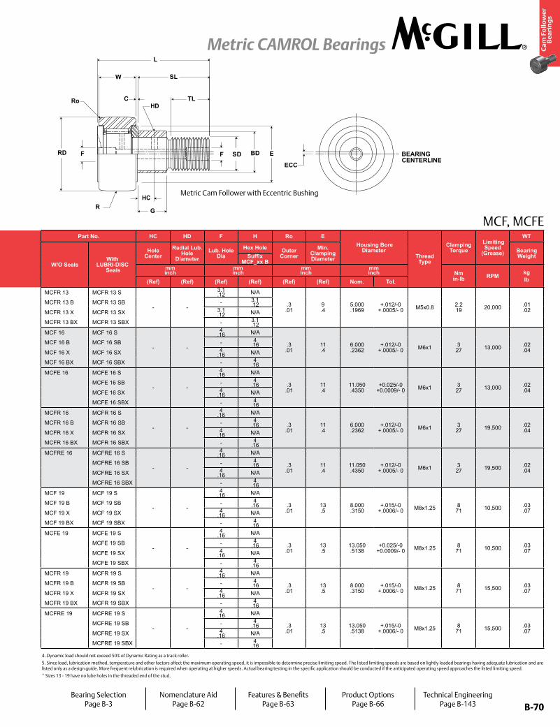
B-70
Ca
m F
oll
ow
er
Be
ari
ng
s
Metric CAMROL Bearings
B-70
HC
HDRo
SD BEARING CENTERLINE
ECC
RD
C
SL
TL
L
E
GR
F BDF
W
Part No. RD W SD SL C TL L R ECC G BDTrack Roller
Dynamic Rating
Track Roller Static Rating
Part No. HC HD F H Ro E Housing Bore
DiameterThread Type
Clamping Torque
Limiting Speed
(Grease)
WT
W/O SealsWith
LUBRI-DISC Seals
Roller Diameter Roller Width Stud Diameter Stud Length
Endplate Extension
Minimum Thread Length
Length Overall
Cylindrical Eccentric
W/O SealsWith
LUBRI-DISC Seals
Hole Center
Radial Lub. Hole
DiameterLub. Hole
DiaHex Hole Outer
CornerMin.
Clamping Diameter
Bearing WeightSuffix
MCF-xx-XBase Modifier
MCFE-xxSuffix
MCF_xx Bmm inch
mm inch
mm inch
mm inch
mm inch
mm inch
mm inch N/lb N/lb
mm inch
mm inch
mm inch
mm inch Nm
in-lb RPM kglbNom. Tol. Nom. Tol. Nom. Tol. (Ref) (Ref) (Ref) (Ref) Radius (Ref) +05/-.15
+.002/-.006 (Ref) (Ref) (Ref) (Ref) (Ref) (Ref) (Ref) Nom. Tol.
MCFR 13 MCFR 13 S
13.000 .5118
+0/-.050 +0/-.002
9.000 .3543
0/-0.12 +0/-0.005
5.000 .1969
+0/-.012 +0/-.0005
13 .5
.60 .024
7.5 .30
23 .9
500 19.7
N/A N/A N/A 2,060 463
1,650 371
MCFR 13 MCFR 13 S
- -
3.1 .12 N/A
.3 .01
9 .4
5.000 .1969
+.012/-0 +.0005/- 0 M5x0.8 2.2
19 20,000 .01 .02
MCFR 13 B MCFR 13 SB MCFR 13 B MCFR 13 SB - 3.1 .12
MCFR 13 X MCFR 13 SX +0/-.008 +0/-.0003 Cylindrical
MCFR 13 X MCFR 13 SX 3.1 .12 N/A
MCFR 13 BX MCFR 13 SBX MCFR 13 BX MCFR 13 SBX - 3.1 .12
MCF 16 MCF 16 S
16.000 .6299
+0/-.050 +0/-.002
11.000 .4331
0/-0.12 +0/-0.005
6.000 .2362
+0/-.012 +0/-.0005
16 .6
.60 .024
9.0 .35
28 1.1
500 19.7
N/A N/A N/A
5,790 1,302
2,350 528
MCF 16 MCF 16 S
- -
4 .16 N/A
.3 .01
11 .4
6.000 .2362
+.012/-0 +.0005/- 0 M6x1 3
27 13,000 .02 .04
MCF 16 B MCF 16 SB MCF 16 B MCF 16 SB - 4 .16
MCF 16 X MCF 16 SX +0/-.008 +0/-.0003 Cylindrical
MCF 16 X MCF 16 SX 4 .16 N/A
MCF 16 BX MCF 16 SBX MCF 16 BX MCF 16 SBX - 4 .16
MCFE 16 MCFE 16 S
16.000 .6299
+0/-.050 +0/-.002
11.000 .4331
0/-0.12 +0/-0.005
6.000 .2362
+0/-.012 +0/-.0005
16 .6
.60 .024
9.0 .35
28 1.1
500 19.7
0.5 .02
7 0.27
9 .35
MCFE 16 MCFE 16 S
- -
4 .16 N/A
.3 .01
11 .4
11.050 .4350
+0.025/-0 +0.0009/- 0 M6x1 3
27 13,000 .02 .04
MCFE 16 SB MCFE 16 SB - 4 .16
MCFE 16 SX +0/-.008 +0/-.0003 Cylindrical
MCFE 16 SX 4 .16 N/A
MCFE 16 SBX MCFE 16 SBX - 4 .16
MCFR 16 MCFR 16 S
16.000 .6299
+0/-.050 +0/-.002
11.000 .4331
0/-0.12 +0/-0.005
6.000 .2362
+0/-.012 +0/-.0005
16 .6
.60 .024
9.0 .35
28 1.1
500 19.7
N/A N/A N/A
3,430 771
2,350 528
MCFR 16 MCFR 16 S
- -
4 .16 N/A
.3 .01
11 .4
6.000 .2362
+.012/-0 +.0005/- 0 M6x1 3
27 19,500 .02 .04
MCFR 16 B MCFR 16 SB MCFR 16 B MCFR 16 SB - 4 .16
MCFR 16 X MCFR 16 SX +0/-.008 +0/-.0003 Cylindrical
MCFR 16 X MCFR 16 SX 4 .16 N/A
MCFR 16 BX MCFR 16 SBX MCFR 16 BX MCFR 16 SBX - 4 .16
MCFRE 16 MCFRE 16 S
16.000 .6299
+0/-.050 +0/-.002
11.000 .4331
0/-0.12 +0/-0.005
6.000 .2362
+0/-.012 +0/-.0005
16 .6
.60 .024
9.0 .35
28 1.1
500 19.7
0.5 .02
7 0.27
9 .35
MCFRE 16 MCFRE 16 S
- -
4 .16 N/A
.3 .01
11 .4
11.050 .4350
+.012/-0 +.0005/- 0 M6x1 3
27 19,500 .02 .04
MCFRE 16 SB MCFRE 16 SB - 4 .16
MCFRE 16 SX +0/-.008 +0/-.0003 Cylindrical
MCFRE 16 SX 4 .16 N/A
MCFRE 16 SBX MCFRE 16 SBX - 4 .16
MCF 19 MCF 19 S
19.000 .7480
+0/-.050 +0/-.002
11.000 .4331
+0/-.12 +0/-.005
8.000 .3150
+0/-.015 +0/-.0006
20 .8
.60 .024
11.0 .43
32 1.3
500 19.7
N/A N/A N/A
6,670 1,500
5,100 1,147
MCF 19 MCF 19 S
- -
4 .16 N/A
.3 .01
13 .5
8.000 .3150
+.015/-0 +.0006/- 0 M8x1.25 8
71 10,500 .03 .07
MCF 19 B MCF 19 SB MCF 19 B MCF 19 SB - 4 .16
MCF 19 X MCF 19 SX +0/-.009 +0/-.0004 Cylindrical
MCF 19 X MCF 19 SX 4 .16 N/A
MCF 19 BX MCF 19 SBX MCF 19 BX MCF 19 SBX - 4 .16
MCFE 19 MCFE 19 S
19.000 .7480
+0/-.050 +0/-.002
11.000 .4331
+0/-.12 +0/-.005
8.000 .3150
+0/-.015 +0/-.0006
20 .8
.60 .024
11.0 .43
32 1.3
500 19.7
0.5 .02
9 0.35
11 .43
MCFE 19 MCFE 19 S
- -
4 .16 N/A
.3 .01
13 .5
13.050 .5138
+0.025/-0 +0.0009/- 0 M8x1.25 8
71 10,500 .03 .07
MCFE 19 SB MCFE 19 SB - 4 .16
MCFE 19 SX +0/-.009 +0/-.0004 Cylindrical
MCFE 19 SX 4 .16 N/A
MCFE 19 SBX MCFE 19 SBX - 4 .16
MCFR 19 MCFR 19 S
19.000 .7480
+0/-.050 +0/-.002
11.000 .4331
+0/-.12 +0/-.005
8.000 .3150
+0/-.015 +0/-.0006
20 .8
.60 .024
11.0 .43
32 1.3
500 19.7
N/A N/A N/A
3,730 839
4,140 931
MCFR 19 MCFR 19 S
- -
4 .16 N/A
.3 .01
13 .5
8.000 .3150
+.015/-0 +.0006/- 0 M8x1.25 8
71 15,500 .03 .07
MCFR 19 B MCFR 19 SB MCFR 19 B MCFR 19 SB - 4 .16
MCFR 19 X MCFR 19 SX +0/-.009 +0/-.0004 Cylindrical
MCFR 19 X MCFR 19 SX 4 .16 N/A
MCFR 19 BX MCFR 19 SBX MCFR 19 BX MCFR 19 SBX - 4 .16
MCFRE 19 MCFRE 19 S
19.000 .7480
+0/-.050 +0/-.002
11.000 .4331
+0/-.12 +0/-.005
8.000 .3150
+0/-.015 +0/-.0006
20 .8
.60 .024
11.0 .43
32 1.3
500 19.7
0.5 .02
9 0.35
11 .43
MCFRE 19 MCFRE 19 S
- -
4 .16 N/A
.3 .01
13 .5
13.050 .5138
+.015/-0 +.0006/- 0 M8x1.25 8
71 15,500 .03 .07
MCFRE 19 SB MCFRE 19 SB - 4 .16
MCFRE 19 SX +0/-.009 +0/-.0004 Cylindrical
MCFRE 19 SX 4 .16 N/A
MCFRE 19 SBX MCFRE 19 SBX - 4 .16
MCF, MCFE
4. Dynamic load should not exceed 50% of Dynamic Rating as a track roller.
5. Since load, lubrication method, temperature and other factors affect the maximum operating speed, it is impossible to determine precise limiting speed. The listed limiting speeds are based on lightly loaded bearings having adequate lubrication and are listed only as a design guide. More frequent relubrication is required when operating at higher speeds. Actual bearing testing in the specific application should be conducted if the anticipated operating speed approaches the listed limiting speed.
* Sizes 13 - 19 have no lube holes in the threaded end of the stud.
Metric Cam Follower with Eccentric Bushing
Bearing SelectionPage B-3
Nomenclature AidPage B-62
Features & BenefitsPage B-63
Product OptionsPage B-66
Technical EngineeringPage B-143
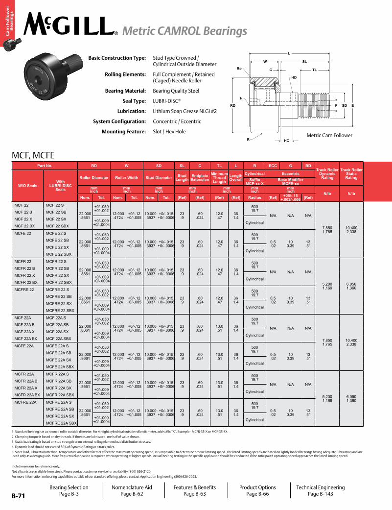
B-71
Ca
m F
oll
ow
er
Be
ari
ng
s
Metric CAMROL Bearings
B-71
MCF, MCFE
Inch dimensions for reference only.
Not all parts are available from stock. Please contact customer service for availability (800) 626-2120.
For more information on bearing capabilities outside of our standard offering, please contact Application Engineering (800) 626-2093.
Basic Construction Type: Stud Type Crowned / Cylindrical Outside Diameter
Rolling Elements: Full Complement / Retained (Caged) Needle Roller
Bearing Material: Bearing Quality Steel
Seal Type: LUBRI-DISC®
Lubrication: Lithium Soap Grease NLGI #2
System Configuration: Concentric / Eccentric
Mounting Feature: Slot / Hex Hole
1. Standard bearing has a crowned roller outside diameter. For straight cylindrical outside roller diameter, add suffix “X”. Example - MCFR-35-X or MCF-35-SX.
2. Clamping torque is based on dry threads. If threads are lubricated, use half of value shown.
3. Static load rating is based on stud strength or on internal rolling element load distribution stresses.
4. Dynamic load should not exceed 50% of Dynamic Rating as a track roller.
5. Since load, lubrication method, temperature and other factors affect the maximum operating speed, it is impossible to determine precise limiting speed. The listed limiting speeds are based on lightly loaded bearings having adequate lubrication and are listed only as a design guide. More frequent relubrication is required when operating at higher speeds. Actual bearing testing in the specific application should be conducted if the anticipated operating speed approaches the listed limiting speed.
Part No. RD W SD SL C TL L R ECC G BDTrack Roller
Dynamic Rating
Track Roller Static Rating
Part No. HC HD F H Ro E Housing Bore
DiameterThread Type
Clamping Torque
Limiting Speed
(Grease)
WT
W/O SealsWith
LUBRI-DISC Seals
Roller Diameter Roller Width Stud Diameter Stud Length
Endplate Extension
Minimum Thread Length
Length Overall
Cylindrical Eccentric
W/O SealsWith
LUBRI-DISC Seals
Hole Center
Radial Lub. Hole
DiameterLub. Hole
DiaHex Hole Outer
CornerMin.
Clamping Diameter
Bearing WeightSuffix
MCF-xx-XBase Modifier
MCFE-xxSuffix
MCF_xx Bmm inch
mm inch
mm inch
mm inch
mm inch
mm inch
mm inch N/lb N/lb
mm inch
mm inch
mm inch
mm inch Nm
in-lb RPM kglbNom. Tol. Nom. Tol. Nom. Tol. (Ref) (Ref) (Ref) (Ref) Radius (Ref) +05/-.15
+.002/-.006 (Ref) (Ref) (Ref) (Ref) (Ref) (Ref) (Ref) Nom. Tol.
MCF 22 MCF 22 S
22.000 .8661
+0/-.050 +0/-.002
12.000 .4724
+0/-.12 +0/-.005
10.000 .3937
+0/-.015 +0/-.0006
23 .9
.60 .024
12.0 .47
36 1.4
500 19.7
N/A N/A N/A
7,850 1,765
10,400 2,338
MCF 22 MCF 22 S
- -
4 .16 N/A
.5 .02
15 .6
10.000 .3937
+.015/-0 +.0006/- 0 M10x1 15
133 9,000 .04 .09
MCF 22 B MCF 22 SB MCF 22 B MCF 22 SB - 4 .16
MCF 22 X MCF 22 SX +0/-.009 +0/-.0004 Cylindrical
MCF 22 X MCF 22 SX 4 .16 N/A
MCF 22 BX MCF 22 SBX MCF 22 BX MCF 22 SBX - 4 .16
MCFE 22 MCFE 22 S
22.000 .8661
+0/-.050 +0/-.002
12.000 .4724
+0/-.12 +0/-.005
10.000 .3937
+0/-.015 +0/-.0006
23 .9
.60 .024
12.0 .47
36 1.4
500 19.7
0.5 .02
10 0.39
13 .51
MCFE 22 MCFE 22 S
- -
4 .16 N/A
.5 .02
15 .6
13.050 .5138
+0.025/-0 +0.0009/- 0 M10x1 15
133 9,000 .04 .09
MCFE 22 SB MCFE 22 SB - 4 .16
MCFE 22 SX +0/-.009 +0/-.0004 Cylindrical
MCFE 22 SX 4 .16 N/A
MCFE 22 SBX MCFE 22 SBX - 4 .16
MCFR 22 MCFR 22 S
22.000 .8661
+0/-.050 +0/-.002
12.000 .4724
+0/-.12 +0/-.005
10.000 .3937
+0/-.015 +0/-.0006
23 .9
.60 .024
12.0 .47
36 1.4
500 19.7
N/A N/A N/A
5,200 1,169
6,050 1,360
MCFR 22 MCFR 22 S
- -
4 .16 N/A
.5 .02
15 .6
10.000 .3937
+.015/-0 +.0006/- 0 M10x1 15
133 13,500 .04 .09
MCFR 22 B MCFR 22 SB MCFR 22 B MCFR 22 SB - 4 .16
MCFR 22 X MCFR 22 SX +0/-.009 +0/-.0004 Cylindrical
MCFR 22 X MCFR 22 SX 4 .16 N/A
MCFR 22 BX MCFR 22 SBX MCFR 22 BX MCFR 22 SBX - 4 .16
MCFRE 22 MCFRE 22 S
22.000 .8661
+0/-.050 +0/-.002
12.000 .4724
+0/-.12 +0/-.005
10.000 .3937
+0/-.015 +0/-.0006
23 .9
.60 .024
12.0 .47
36 1.4
500 19.7
0.5 .02
10 0.39
13 .51
MCFRE 22 MCFRE 22 S
- -
4 .16 N/A
.5 .02
15 .6
13.050 .5138
+0.025/-0 +0.0009/- 0 M10x1 15
133 13,500 .04 .09
MCFRE 22 SB MCFRE 22 SB - 4 .16
MCFRE 22 SX +0/-.009 +0/-.0004 Cylindrical
MCFRE 22 SX 4 .16 N/A
MCFRE 22 SBX MCFRE 22 SBX - 4 .16
MCF 22A MCF 22A S
22.000 .8661
+0/-.050 +0/-.002
12.000 .4724
+0/-.12 +0/-.005
10.000 .3937
+0/-.015 +0/-.0006
23 .9
.60 .024
13.0 .51
36 1.4
500 19.7
N/A N/A N/A
7,850 1,765
10,400 2,338
MCF 22A MCF 22A S
- -
4 .16 N/A
.5 .02
15 .6
10.000 .3937
+.015/-0 +.0006/- 0 M10x1.25 15
133 9,000 .04 .09
MCF 22A B MCF 22A SB MCF 22A B MCF 22A SB - 5 .2
MCF 22A X MCF 22A SX +0/-.009 +0/-.0004 Cylindrical
MCF 22A X MCF 22A SX 4 .16 N/A
MCF 22A BX MCF 22A SBX MCF 22A BX MCF 22A SBX - 5 .2
MCFE 22A MCFE 22A S
22.000 .8661
+0/-.050 +0/-.002
12.000 .4724
+0/-.12 +0/-.005
10.000 .3937
+0/-.015 +0/-.0006
23 .9
.60 .024
13.0 .51
36 1.4
500 19.7
0.5 .02
10 0.39
13 .51
MCFE 22A MCFE 22A S
- -
4 .16 N/A
.5 .02
15 .6
13.050 .5138
+0.025/-0 +0.0009/- 0 M10x1.25 15
133 9,000 .04 .09
MCFE 22A SB MCFE 22A SB - 5 .2
MCFE 22A SX +0/-.009 +0/-.0004 Cylindrical
MCFE 22A SX 4 .16 N/A
MCFE 22A SBX MCFE 22A SBX - 5 .2
MCFR 22A MCFR 22A S
22.000 .8661
+0/-.050 +0/-.002
12.000 .4724
+0/-.12 +0/-.005
10.000 .3937
+0/-.015 +0/-.0006
23 .9
.60 .024
13.0 .51
36 1.4
500 19.7
N/A N/A N/A
5,200 1,169
6,050 1,360
MCFR 22A MCFR 22A S
- -
4 .16 N/A
.5 .02
15 .6
10.000 .3937
+.015/-0 +.0006/- 0 M10x1.25 15
133 13,500 .04 .09
MCFR 22A B MCFR 22A SB MCFR 22A B MCFR 22A SB - 5 .2
MCFR 22A X MCFR 22A SX +0/-.009 +0/-.0004 Cylindrical
MCFR 22A X MCFR 22A SX 4 .2 N/A
MCFR 22A BX MCFR 22A SBX MCFR 22A BX MCFR 22A SBX - 5 .2
MCFRE 22A MCFRE 22A S
22.000 .8661
+0/-.050 +0/-.002
12.000 .4724
+0/-.12 +0/-.005
10.000 .3937
+0/-.015 +0/-.0006
23 .9
.60 .024
13.0 .51
36 1.4
500 19.7
0.5 .02
10 0.39
13 .51
MCFRE 22A MCFRE 22A S
- -
4 .16 N/A
.5 .02
15 .6
13.050 .5138
+0.025/-0 +0.0009/- 0 M10x1.25 15
133 13,500 .04 .09
MCFRE 22A SB MCFRE 22A SB - 5 .2
MCFRE 22A SX +0/-.009 +0/-.0004 Cylindrical
MCFRE 22A SX 4 .16 N/A
MCFRE 22A SBX MCFRE 22A SBX - 5 .2
W
C
SL
TL
F SD E
HC
RD
H
HD
Ro
L
RMetric Cam Follower
Bearing SelectionPage B-3
Nomenclature AidPage B-62
Features & BenefitsPage B-63
Product OptionsPage B-66
Technical EngineeringPage B-143
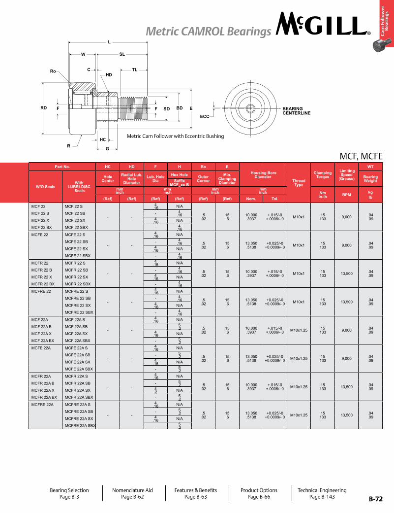
B-72
Ca
m F
oll
ow
er
Be
ari
ng
s
Metric CAMROL Bearings
B-72
MCF, MCFEPart No. RD W SD SL C TL L R ECC G BD
Track Roller Dynamic Rating
Track Roller Static Rating
Part No. HC HD F H Ro E Housing Bore
DiameterThread Type
Clamping Torque
Limiting Speed
(Grease)
WT
W/O SealsWith
LUBRI-DISC Seals
Roller Diameter Roller Width Stud Diameter Stud Length
Endplate Extension
Minimum Thread Length
Length Overall
Cylindrical Eccentric
W/O SealsWith
LUBRI-DISC Seals
Hole Center
Radial Lub. Hole
DiameterLub. Hole
DiaHex Hole Outer
CornerMin.
Clamping Diameter
Bearing WeightSuffix
MCF-xx-XBase Modifier
MCFE-xxSuffix
MCF_xx Bmm inch
mm inch
mm inch
mm inch
mm inch
mm inch
mm inch N/lb N/lb
mm inch
mm inch
mm inch
mm inch Nm
in-lb RPM kglbNom. Tol. Nom. Tol. Nom. Tol. (Ref) (Ref) (Ref) (Ref) Radius (Ref) +05/-.15
+.002/-.006 (Ref) (Ref) (Ref) (Ref) (Ref) (Ref) (Ref) Nom. Tol.
MCF 22 MCF 22 S
22.000 .8661
+0/-.050 +0/-.002
12.000 .4724
+0/-.12 +0/-.005
10.000 .3937
+0/-.015 +0/-.0006
23 .9
.60 .024
12.0 .47
36 1.4
500 19.7
N/A N/A N/A
7,850 1,765
10,400 2,338
MCF 22 MCF 22 S
- -
4 .16 N/A
.5 .02
15 .6
10.000 .3937
+.015/-0 +.0006/- 0 M10x1 15
133 9,000 .04 .09
MCF 22 B MCF 22 SB MCF 22 B MCF 22 SB - 4 .16
MCF 22 X MCF 22 SX +0/-.009 +0/-.0004 Cylindrical
MCF 22 X MCF 22 SX 4 .16 N/A
MCF 22 BX MCF 22 SBX MCF 22 BX MCF 22 SBX - 4 .16
MCFE 22 MCFE 22 S
22.000 .8661
+0/-.050 +0/-.002
12.000 .4724
+0/-.12 +0/-.005
10.000 .3937
+0/-.015 +0/-.0006
23 .9
.60 .024
12.0 .47
36 1.4
500 19.7
0.5 .02
10 0.39
13 .51
MCFE 22 MCFE 22 S
- -
4 .16 N/A
.5 .02
15 .6
13.050 .5138
+0.025/-0 +0.0009/- 0 M10x1 15
133 9,000 .04 .09
MCFE 22 SB MCFE 22 SB - 4 .16
MCFE 22 SX +0/-.009 +0/-.0004 Cylindrical
MCFE 22 SX 4 .16 N/A
MCFE 22 SBX MCFE 22 SBX - 4 .16
MCFR 22 MCFR 22 S
22.000 .8661
+0/-.050 +0/-.002
12.000 .4724
+0/-.12 +0/-.005
10.000 .3937
+0/-.015 +0/-.0006
23 .9
.60 .024
12.0 .47
36 1.4
500 19.7
N/A N/A N/A
5,200 1,169
6,050 1,360
MCFR 22 MCFR 22 S
- -
4 .16 N/A
.5 .02
15 .6
10.000 .3937
+.015/-0 +.0006/- 0 M10x1 15
133 13,500 .04 .09
MCFR 22 B MCFR 22 SB MCFR 22 B MCFR 22 SB - 4 .16
MCFR 22 X MCFR 22 SX +0/-.009 +0/-.0004 Cylindrical
MCFR 22 X MCFR 22 SX 4 .16 N/A
MCFR 22 BX MCFR 22 SBX MCFR 22 BX MCFR 22 SBX - 4 .16
MCFRE 22 MCFRE 22 S
22.000 .8661
+0/-.050 +0/-.002
12.000 .4724
+0/-.12 +0/-.005
10.000 .3937
+0/-.015 +0/-.0006
23 .9
.60 .024
12.0 .47
36 1.4
500 19.7
0.5 .02
10 0.39
13 .51
MCFRE 22 MCFRE 22 S
- -
4 .16 N/A
.5 .02
15 .6
13.050 .5138
+0.025/-0 +0.0009/- 0 M10x1 15
133 13,500 .04 .09
MCFRE 22 SB MCFRE 22 SB - 4 .16
MCFRE 22 SX +0/-.009 +0/-.0004 Cylindrical
MCFRE 22 SX 4 .16 N/A
MCFRE 22 SBX MCFRE 22 SBX - 4 .16
MCF 22A MCF 22A S
22.000 .8661
+0/-.050 +0/-.002
12.000 .4724
+0/-.12 +0/-.005
10.000 .3937
+0/-.015 +0/-.0006
23 .9
.60 .024
13.0 .51
36 1.4
500 19.7
N/A N/A N/A
7,850 1,765
10,400 2,338
MCF 22A MCF 22A S
- -
4 .16 N/A
.5 .02
15 .6
10.000 .3937
+.015/-0 +.0006/- 0 M10x1.25 15
133 9,000 .04 .09
MCF 22A B MCF 22A SB MCF 22A B MCF 22A SB - 5 .2
MCF 22A X MCF 22A SX +0/-.009 +0/-.0004 Cylindrical
MCF 22A X MCF 22A SX 4 .16 N/A
MCF 22A BX MCF 22A SBX MCF 22A BX MCF 22A SBX - 5 .2
MCFE 22A MCFE 22A S
22.000 .8661
+0/-.050 +0/-.002
12.000 .4724
+0/-.12 +0/-.005
10.000 .3937
+0/-.015 +0/-.0006
23 .9
.60 .024
13.0 .51
36 1.4
500 19.7
0.5 .02
10 0.39
13 .51
MCFE 22A MCFE 22A S
- -
4 .16 N/A
.5 .02
15 .6
13.050 .5138
+0.025/-0 +0.0009/- 0 M10x1.25 15
133 9,000 .04 .09
MCFE 22A SB MCFE 22A SB - 5 .2
MCFE 22A SX +0/-.009 +0/-.0004 Cylindrical
MCFE 22A SX 4 .16 N/A
MCFE 22A SBX MCFE 22A SBX - 5 .2
MCFR 22A MCFR 22A S
22.000 .8661
+0/-.050 +0/-.002
12.000 .4724
+0/-.12 +0/-.005
10.000 .3937
+0/-.015 +0/-.0006
23 .9
.60 .024
13.0 .51
36 1.4
500 19.7
N/A N/A N/A
5,200 1,169
6,050 1,360
MCFR 22A MCFR 22A S
- -
4 .16 N/A
.5 .02
15 .6
10.000 .3937
+.015/-0 +.0006/- 0 M10x1.25 15
133 13,500 .04 .09
MCFR 22A B MCFR 22A SB MCFR 22A B MCFR 22A SB - 5 .2
MCFR 22A X MCFR 22A SX +0/-.009 +0/-.0004 Cylindrical
MCFR 22A X MCFR 22A SX 4 .2 N/A
MCFR 22A BX MCFR 22A SBX MCFR 22A BX MCFR 22A SBX - 5 .2
MCFRE 22A MCFRE 22A S
22.000 .8661
+0/-.050 +0/-.002
12.000 .4724
+0/-.12 +0/-.005
10.000 .3937
+0/-.015 +0/-.0006
23 .9
.60 .024
13.0 .51
36 1.4
500 19.7
0.5 .02
10 0.39
13 .51
MCFRE 22A MCFRE 22A S
- -
4 .16 N/A
.5 .02
15 .6
13.050 .5138
+0.025/-0 +0.0009/- 0 M10x1.25 15
133 13,500 .04 .09
MCFRE 22A SB MCFRE 22A SB - 5 .2
MCFRE 22A SX +0/-.009 +0/-.0004 Cylindrical
MCFRE 22A SX 4 .16 N/A
MCFRE 22A SBX MCFRE 22A SBX - 5 .2
Metric Cam Follower with Eccentric Bushing
Bearing SelectionPage B-3
Nomenclature AidPage B-62
Features & BenefitsPage B-63
Product OptionsPage B-66
Technical EngineeringPage B-143
HC
HDRo
SD BEARING CENTERLINE
ECC
RD
C
SL
TL
L
E
GR
F BDF
W
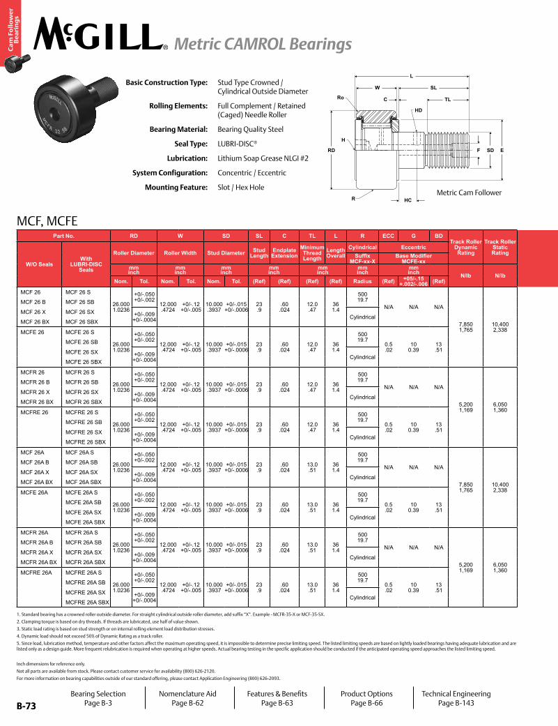
B-73
Ca
m F
oll
ow
er
Be
ari
ng
s
Metric CAMROL Bearings
B-73
MCF, MCFE
Inch dimensions for reference only.
Not all parts are available from stock. Please contact customer service for availability (800) 626-2120.
For more information on bearing capabilities outside of our standard offering, please contact Application Engineering (800) 626-2093.
Basic Construction Type: Stud Type Crowned / Cylindrical Outside Diameter
Rolling Elements: Full Complement / Retained (Caged) Needle Roller
Bearing Material: Bearing Quality Steel
Seal Type: LUBRI-DISC®
Lubrication: Lithium Soap Grease NLGI #2
System Configuration: Concentric / Eccentric
Mounting Feature: Slot / Hex Hole
1. Standard bearing has a crowned roller outside diameter. For straight cylindrical outside roller diameter, add suffix “X”. Example - MCFR-35-X or MCF-35-SX.
2. Clamping torque is based on dry threads. If threads are lubricated, use half of value shown.
3. Static load rating is based on stud strength or on internal rolling element load distribution stresses.
4. Dynamic load should not exceed 50% of Dynamic Rating as a track roller.
5. Since load, lubrication method, temperature and other factors affect the maximum operating speed, it is impossible to determine precise limiting speed. The listed limiting speeds are based on lightly loaded bearings having adequate lubrication and are listed only as a design guide. More frequent relubrication is required when operating at higher speeds. Actual bearing testing in the specific application should be conducted if the anticipated operating speed approaches the listed limiting speed.
Part No. RD W SD SL C TL L R ECC G BDTrack Roller
Dynamic Rating
Track Roller Static Rating
Part No. HC HD F H Ro E Housing Bore
DiameterThread Type
Clamping Torque
Limiting Speed
(Grease)
WT
W/O SealsWith
LUBRI-DISC Seals
Roller Diameter Roller Width Stud Diameter Stud Length
Endplate Extension
Minimum Thread Length
Length Overall
Cylindrical Eccentric
W/O SealsWith
LUBRI-DISC Seals
Hole Center
Radial Lub. Hole
DiameterLub. Hole
DiaHex Hole Outer
CornerMin.
Clamping Diameter
Bearing WeightSuffix
MCF-xx-XBase Modifier
MCFE-xxSuffix
MCF_xx Bmm inch
mm inch
mm inch
mm inch
mm inch
mm inch
mm inch N/lb N/lb
mm inch
mm inch
mm inch
mm inch Nm
in-lb RPM kglbNom. Tol. Nom. Tol. Nom. Tol. (Ref) (Ref) (Ref) (Ref) Radius (Ref) +05/-.15
+.002/-.006 (Ref) (Ref) (Ref) (Ref) (Ref) (Ref) (Ref) Nom. Tol.
MCF 26 MCF 26 S
26.000 1.0236
+0/-.050 +0/-.002
12.000 .4724
+0/-.12 +0/-.005
10.000 .3937
+0/-.015 +0/-.0006
23 .9
.60 .024
12.0 .47
36 1.4
500 19.7
N/A N/A N/A
7,850 1,765
10,400 2,338
MCF 26 MCF 26 S
- -
4 .16 N/A
.5 .02
15 .6
10.000 .3937
+.015/-0 +.0006/- 0 M10x1 15
133 9,000 .05 .11
MCF 26 B MCF 26 SB MCF 26 B MCF 26 SB - 4 .16
MCF 26 X MCF 26 SX +0/-.009 +0/-.0004 Cylindrical
MCF 26 X MCF 26 SX 4 .16 N/A
MCF 26 BX MCF 26 SBX MCF 26 BX MCF 26 SBX - 4 .16
MCFE 26 MCFE 26 S
26.000 1.0236
+0/-.050 +0/-.002
12.000 .4724
+0/-.12 +0/-.005
10.000 .3937
+0/-.015 +0/-.0006
23 .9
.60 .024
12.0 .47
36 1.4
500 19.7
0.5 .02
10 0.39
13 .51
MCFE 26 MCFE 26 S
- -
4 .16 N/A
.5 .02
15 .6
13.050 .5138
+0.025/-0 +0.0009/- 0 M10x1 15
133 9,000 .05 .11
MCFE 26 SB MCFE 26 SB - 4 .16
MCFE 26 SX +0/-.009 +0/-.0004 Cylindrical
MCFE 26 SX 4 .16 N/A
MCFE 26 SBX MCFE 26 SBX - 4 .16
MCFR 26 MCFR 26 S
26.000 1.0236
+0/-.050 +0/-.002
12.000 .4724
+0/-.12 +0/-.005
10.000 .3937
+0/-.015 +0/-.0006
23 .9
.60 .024
12.0 .47
36 1.4
500 19.7
N/A N/A N/A
5,200 1,169
6,050 1,360
MCFR 26 MCFR 26 S
- -
4 .16 N/A
.5 .02
15 .6
10.000 .3937
+.015/-0 +.0006/- 0 M10x1 15
133 13,500 .05 .11
MCFR 26 B MCFR 26 SB MCFR 26 B MCFR 26 SB - 4 .16
MCFR 26 X MCFR 26 SX +0/-.009 +0/-.0004 Cylindrical
MCFR 26 X MCFR 26 SX 4 .16 N/A
MCFR 26 BX MCFR 26 SBX MCFR 26 BX MCFR 26 SBX - 4 .16
MCFRE 26 MCFRE 26 S
26.000 1.0236
+0/-.050 +0/-.002
12.000 .4724
+0/-.12 +0/-.005
10.000 .3937
+0/-.015 +0/-.0006
23 .9
.60 .024
12.0 .47
36 1.4
500 19.7
0.5 .02
10 0.39
13 .51
MCFRE 26 MCFRE 26 S
- -
4 .16 N/A
.5 .02
15 .6
13.050 .5138
+0.025/-0 +0.0009/- 0 M10x1 15
133 13,500 .05 .11
MCFRE 26 SB MCFRE 26 SB - 4 .16
MCFRE 26 SX +0/-.009 +0/-.0004 Cylindrical
MCFRE 26 SX 4 .16 N/A
MCFRE 26 SBX MCFRE 26 SBX - 4 .16
MCF 26A MCF 26A S
26.000 1.0236
+0/-.050 +0/-.002
12.000 .4724
+0/-.12 +0/-.005
10.000 .3937
+0/-.015 +0/-.0006
23 .9
.60 .024
13.0 .51
36 1.4
500 19.7
N/A N/A N/A
7,850 1,765
10,400 2,338
MCF 26A MCF 26A S
- -
4 .16 N/A
.5 .02
19 .7
10.000 .3937
+.015/-0 +.0006/- 0 M10x1.25 22
195 9,000 .05 .11
MCF 26A B MCF 26A SB MCF 26A B MCF 26A SB - 5 .2
MCF 26A X MCF 26A SX +0/-.009 +0/-.0004 Cylindrical
MCF 26A X MCF 26A SX 4 .16 N/A
MCF 26A BX MCF 26A SBX MCF 26A BX MCF 26A SBX - 5 .2
MCFE 26A MCFE 26A S
26.000 1.0236
+0/-.050 +0/-.002
12.000 .4724
+0/-.12 +0/-.005
10.000 .3937
+0/-.015 +0/-.0006
23 .9
.60 .024
13.0 .51
36 1.4
500 19.7
0.5 .02
10 0.39
13 .51
MCFE 26A MCFE 26A S
- -
4 .16 N/A
.5 .02
19 .7
13.050 .5138
+0.025/-0 +0.0009/- 0 M10x1.25 22
195 9,000 .05 .11
MCFE 26A SB MCFE 26A SB - 5 .2
MCFE 26A SX +0/-.009 +0/-.0004 Cylindrical
MCFE 26A SX 4 .16 N/A
MCFE 26A SBX MCFE 26A SBX - 5 .2
MCFR 26A MCFR 26A S
26.000 1.0236
+0/-.050 +0/-.002
12.000 .4724
+0/-.12 +0/-.005
10.000 .3937
+0/-.015 +0/-.0006
23 .9
.60 .024
13.0 .51
36 1.4
500 19.7
N/A N/A N/A
5,200 1,169
6,050 1,360
MCFR 26A MCFR 26A S
- -
4 .16 N/A
.5 .02
19 .7
10.000 .3937
+.015/-0 +.0006/- 0 M10x1.25 22
195 13,500 .05 .11
MCFR 26A B MCFR 26A SB MCFR 26A B MCFR 26A SB - 5 .2
MCFR 26A X MCFR 26A SX +0/-.009 +0/-.0004 Cylindrical
MCFR 26A X MCFR 26A SX 4 .16 N/A
MCFR 26A BX MCFR 26A SBX MCFR 26A BX MCFR 26A SBX - 5 .2
MCFRE 26A MCFRE 26A S
26.000 1.0236
+0/-.050 +0/-.002
12.000 .4724
+0/-.12 +0/-.005
10.000 .3937
+0/-.015 +0/-.0006
23 .9
.60 .024
13.0 .51
36 1.4
500 19.7
0.5 .02
10 0.39
13 .51
MCFRE 26A MCFRE 26A S
- -
4 .16 N/A
.5 .02
19 .7
13.050 .5138
+0.025/-0 +0.0009/- 0 M10x1.25 22
195 13,500 .05 .11
MCFRE 26A SB MCFRE 26A SB - 5 .2
MCFRE 26A SX +0/-.009 +0/-.0004 Cylindrical
MCFRE 26A SX 4 .16 N/A
MCFRE 26A SBX MCFRE 26A SBX - 5 .2
W
C
SL
TL
F SD E
HC
RD
H
HD
Ro
L
RMetric Cam Follower
Bearing SelectionPage B-3
Nomenclature AidPage B-62
Features & BenefitsPage B-63
Product OptionsPage B-66
Technical EngineeringPage B-143
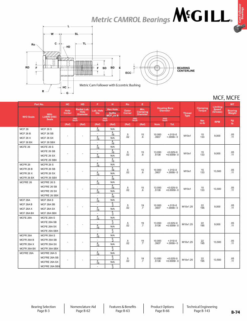
B-74
Ca
m F
oll
ow
er
Be
ari
ng
s
Metric CAMROL Bearings
B-74
MCF, MCFEPart No. RD W SD SL C TL L R ECC G BD
Track Roller Dynamic Rating
Track Roller Static Rating
Part No. HC HD F H Ro E Housing Bore
DiameterThread Type
Clamping Torque
Limiting Speed
(Grease)
WT
W/O SealsWith
LUBRI-DISC Seals
Roller Diameter Roller Width Stud Diameter Stud Length
Endplate Extension
Minimum Thread Length
Length Overall
Cylindrical Eccentric
W/O SealsWith
LUBRI-DISC Seals
Hole Center
Radial Lub. Hole
DiameterLub. Hole
DiaHex Hole Outer
CornerMin.
Clamping Diameter
Bearing WeightSuffix
MCF-xx-XBase Modifier
MCFE-xxSuffix
MCF_xx Bmm inch
mm inch
mm inch
mm inch
mm inch
mm inch
mm inch N/lb N/lb
mm inch
mm inch
mm inch
mm inch Nm
in-lb RPM kglbNom. Tol. Nom. Tol. Nom. Tol. (Ref) (Ref) (Ref) (Ref) Radius (Ref) +05/-.15
+.002/-.006 (Ref) (Ref) (Ref) (Ref) (Ref) (Ref) (Ref) Nom. Tol.
MCF 26 MCF 26 S
26.000 1.0236
+0/-.050 +0/-.002
12.000 .4724
+0/-.12 +0/-.005
10.000 .3937
+0/-.015 +0/-.0006
23 .9
.60 .024
12.0 .47
36 1.4
500 19.7
N/A N/A N/A
7,850 1,765
10,400 2,338
MCF 26 MCF 26 S
- -
4 .16 N/A
.5 .02
15 .6
10.000 .3937
+.015/-0 +.0006/- 0 M10x1 15
133 9,000 .05 .11
MCF 26 B MCF 26 SB MCF 26 B MCF 26 SB - 4 .16
MCF 26 X MCF 26 SX +0/-.009 +0/-.0004 Cylindrical
MCF 26 X MCF 26 SX 4 .16 N/A
MCF 26 BX MCF 26 SBX MCF 26 BX MCF 26 SBX - 4 .16
MCFE 26 MCFE 26 S
26.000 1.0236
+0/-.050 +0/-.002
12.000 .4724
+0/-.12 +0/-.005
10.000 .3937
+0/-.015 +0/-.0006
23 .9
.60 .024
12.0 .47
36 1.4
500 19.7
0.5 .02
10 0.39
13 .51
MCFE 26 MCFE 26 S
- -
4 .16 N/A
.5 .02
15 .6
13.050 .5138
+0.025/-0 +0.0009/- 0 M10x1 15
133 9,000 .05 .11
MCFE 26 SB MCFE 26 SB - 4 .16
MCFE 26 SX +0/-.009 +0/-.0004 Cylindrical
MCFE 26 SX 4 .16 N/A
MCFE 26 SBX MCFE 26 SBX - 4 .16
MCFR 26 MCFR 26 S
26.000 1.0236
+0/-.050 +0/-.002
12.000 .4724
+0/-.12 +0/-.005
10.000 .3937
+0/-.015 +0/-.0006
23 .9
.60 .024
12.0 .47
36 1.4
500 19.7
N/A N/A N/A
5,200 1,169
6,050 1,360
MCFR 26 MCFR 26 S
- -
4 .16 N/A
.5 .02
15 .6
10.000 .3937
+.015/-0 +.0006/- 0 M10x1 15
133 13,500 .05 .11
MCFR 26 B MCFR 26 SB MCFR 26 B MCFR 26 SB - 4 .16
MCFR 26 X MCFR 26 SX +0/-.009 +0/-.0004 Cylindrical
MCFR 26 X MCFR 26 SX 4 .16 N/A
MCFR 26 BX MCFR 26 SBX MCFR 26 BX MCFR 26 SBX - 4 .16
MCFRE 26 MCFRE 26 S
26.000 1.0236
+0/-.050 +0/-.002
12.000 .4724
+0/-.12 +0/-.005
10.000 .3937
+0/-.015 +0/-.0006
23 .9
.60 .024
12.0 .47
36 1.4
500 19.7
0.5 .02
10 0.39
13 .51
MCFRE 26 MCFRE 26 S
- -
4 .16 N/A
.5 .02
15 .6
13.050 .5138
+0.025/-0 +0.0009/- 0 M10x1 15
133 13,500 .05 .11
MCFRE 26 SB MCFRE 26 SB - 4 .16
MCFRE 26 SX +0/-.009 +0/-.0004 Cylindrical
MCFRE 26 SX 4 .16 N/A
MCFRE 26 SBX MCFRE 26 SBX - 4 .16
MCF 26A MCF 26A S
26.000 1.0236
+0/-.050 +0/-.002
12.000 .4724
+0/-.12 +0/-.005
10.000 .3937
+0/-.015 +0/-.0006
23 .9
.60 .024
13.0 .51
36 1.4
500 19.7
N/A N/A N/A
7,850 1,765
10,400 2,338
MCF 26A MCF 26A S
- -
4 .16 N/A
.5 .02
19 .7
10.000 .3937
+.015/-0 +.0006/- 0 M10x1.25 22
195 9,000 .05 .11
MCF 26A B MCF 26A SB MCF 26A B MCF 26A SB - 5 .2
MCF 26A X MCF 26A SX +0/-.009 +0/-.0004 Cylindrical
MCF 26A X MCF 26A SX 4 .16 N/A
MCF 26A BX MCF 26A SBX MCF 26A BX MCF 26A SBX - 5 .2
MCFE 26A MCFE 26A S
26.000 1.0236
+0/-.050 +0/-.002
12.000 .4724
+0/-.12 +0/-.005
10.000 .3937
+0/-.015 +0/-.0006
23 .9
.60 .024
13.0 .51
36 1.4
500 19.7
0.5 .02
10 0.39
13 .51
MCFE 26A MCFE 26A S
- -
4 .16 N/A
.5 .02
19 .7
13.050 .5138
+0.025/-0 +0.0009/- 0 M10x1.25 22
195 9,000 .05 .11
MCFE 26A SB MCFE 26A SB - 5 .2
MCFE 26A SX +0/-.009 +0/-.0004 Cylindrical
MCFE 26A SX 4 .16 N/A
MCFE 26A SBX MCFE 26A SBX - 5 .2
MCFR 26A MCFR 26A S
26.000 1.0236
+0/-.050 +0/-.002
12.000 .4724
+0/-.12 +0/-.005
10.000 .3937
+0/-.015 +0/-.0006
23 .9
.60 .024
13.0 .51
36 1.4
500 19.7
N/A N/A N/A
5,200 1,169
6,050 1,360
MCFR 26A MCFR 26A S
- -
4 .16 N/A
.5 .02
19 .7
10.000 .3937
+.015/-0 +.0006/- 0 M10x1.25 22
195 13,500 .05 .11
MCFR 26A B MCFR 26A SB MCFR 26A B MCFR 26A SB - 5 .2
MCFR 26A X MCFR 26A SX +0/-.009 +0/-.0004 Cylindrical
MCFR 26A X MCFR 26A SX 4 .16 N/A
MCFR 26A BX MCFR 26A SBX MCFR 26A BX MCFR 26A SBX - 5 .2
MCFRE 26A MCFRE 26A S
26.000 1.0236
+0/-.050 +0/-.002
12.000 .4724
+0/-.12 +0/-.005
10.000 .3937
+0/-.015 +0/-.0006
23 .9
.60 .024
13.0 .51
36 1.4
500 19.7
0.5 .02
10 0.39
13 .51
MCFRE 26A MCFRE 26A S
- -
4 .16 N/A
.5 .02
19 .7
13.050 .5138
+0.025/-0 +0.0009/- 0 M10x1.25 22
195 13,500 .05 .11
MCFRE 26A SB MCFRE 26A SB - 5 .2
MCFRE 26A SX +0/-.009 +0/-.0004 Cylindrical
MCFRE 26A SX 4 .16 N/A
MCFRE 26A SBX MCFRE 26A SBX - 5 .2
Metric Cam Follower with Eccentric Bushing
Bearing SelectionPage B-3
Nomenclature AidPage B-62
Features & BenefitsPage B-63
Product OptionsPage B-66
Technical EngineeringPage B-143
HC
HDRo
SD BEARING CENTERLINE
ECC
RD
C
SL
TL
L
E
GR
F BDF
W

B-75
Ca
m F
oll
ow
er
Be
ari
ng
s
Metric CAMROL Bearings
B-75
MCF, MCFE
Inch dimensions for reference only.
Not all parts are available from stock. Please contact customer service for availability (800) 626-2120.
For more information on bearing capabilities outside of our standard offering, please contact Application Engineering (800) 626-2093.
Basic Construction Type: Stud Type Crowned / Cylindrical Outside Diameter
Rolling Elements: Full Complement / Retained (Caged) Needle Roller
Bearing Material: Bearing Quality Steel
Seal Type: LUBRI-DISC®
Lubrication: Lithium Soap Grease NLGI #2
System Configuration: Concentric / Eccentric
Mounting Feature: Slot / Hex Hole
1. Standard bearing has a crowned roller outside diameter. For straight cylindrical outside roller diameter, add suffix “X”. Example - MCFR-35-X or MCF-35-SX.
2. Clamping torque is based on dry threads. If threads are lubricated, use half of value shown.
3. Static load rating is based on stud strength or on internal rolling element load distribution stresses.
4. Dynamic load should not exceed 50% of Dynamic Rating as a track roller.
5. Since load, lubrication method, temperature and other factors affect the maximum operating speed, it is impossible to determine precise limiting speed. The listed limiting speeds are based on lightly loaded bearings having adequate lubrication and are listed only as a design guide. More frequent relubrication is required when operating at higher speeds. Actual bearing testing in the specific application should be conducted if the anticipated operating speed approaches the listed limiting speed.
Part No. RD W SD SL C TL L R ECC G BDTrack Roller
Dynamic Rating
Track Roller Static Rating
Part No. HC HD F H Ro E Housing Bore
DiameterThread Type
Clamping Torque
Limiting Speed
(Grease)
WT
W/O SealsWith
LUBRI-DISC Seals
Roller Diameter Roller Width Stud Diameter Stud Length
Endplate Extension
Minimum Thread Length
Length Overall
Cylindrical Eccentric
W/O SealsWith
LUBRI-DISC Seals
Hole Center
Radial Lub. Hole
DiameterLub. Hole
DiaHex Hole Outer
CornerMin.
Clamping Diameter
Bearing WeightSuffix
MCF-xx-XBase Modifier
MCFE-xxSuffix
MCF_xx Bmm inch
mm inch
mm inch
mm inch
mm inch
mm inch
mm inch N/lb N/lb
mm inch
mm inch
mm inch
mm inch Nm
in-lb RPM kglbNom. Tol. Nom. Tol. Nom. Tol. (Ref) (Ref) (Ref) (Ref) Radius (Ref) +05/-.15
+.002/-.006 (Ref) (Ref) (Ref) (Ref) (Ref) (Ref) (Ref) Nom. Tol.
MCF 30 MCF 30 S
30.000 1.1811
+0/-.050 +0/-.002
14.000 .5512
+0/-.12 +0/-.005
12.000 .4724
+0/-.018 +0/-.0007
25 .9
.60 .024
14.0 .55
40 1.6
500 19.7
N/A N/A N/A
11,080 2,491
15,300 3,440
MCF 30 MCF 30 S
6 .236
3 .118
6 .24 N/A
1.0 .04
19 .7
12.000 .4724
+.018/-0 +.0007/- 0 M12x1.5 22
195 6,400 .09 .20
MCF 30 B MCF 30 SB MCF 30 B MCF 30 SB - 6 .24
MCF 30 X MCF 30 SX +0/-.009 +0/-.0004 Cylindrical
MCF 30 X MCF 30 SX 6 .24 N/A
MCF 30 BX MCF 30 SBX MCF 30 BX MCF 30 SBX - 6 .24
MCFE 30 MCFE 30 S
30.000 1.1811
+0/-.050 +0/-.002
14.000 .5512
+0/-.12 +0/-.005
12.000 .4724
+0/-.018 +0/-.0007
25 .9
.60 .024
14.0 .55
40 1.6
500 19.7
0.5 .02
11 0.43
15 .59
MCFE 30 MCFE 30 S
N/A N/A
6 .24 N/A
1.0 .04
19 .7
15.050 .5925
+0.025/-0 +0.0009/- 0 M12x1.5 22
195 6,400 .09 .20
MCFE 30 SB MCFE 30 SB - 6 .24
MCFE 30 SX +0/-.009 +0/-.0004 Cylindrical
MCFE 30 SX 6 .24 N/A
MCFE 30 SBX MCFE 30 SBX - 6 .24
MCFR 30 MCFR 30 S
30.000 1.1811
+0/-.050 +0/-.002
14.000 .5512
+0/-.12 +0/-.005
12.000 .4724
+0/-.018 +0/-.0007
25 .9
.60 .024
14.0 .55
40 1.6
500 19.7
N/A N/A N/A
6,860 1,542
8,050 1,810
MCFR 30 MCFR 30 S
6 .236
3 .118
6 .24 N/A
1.0 .04
19 .7
12.000 .4724
+.018/-0 +.0007/- 0 M12x1.5 22
195 9,600 .09 .20
MCFR 30 B MCFR 30 SB MCFR 30 B MCFR 30 SB - 6 .24
MCFR 30 X MCFR 30 SX +0/-.009 +0/-.0004 Cylindrical
MCFR 30 X MCFR 30 SX 6 .24 N/A
MCFR 30 BX MCFR 30 SBX MCFR 30 BX MCFR 30 SBX - 6 .24
MCFRE 30 MCFRE 30 S
30.000 1.1811
+0/-.050 +0/-.002
14.000 .5512
+0/-.12 +0/-.005
12.000 .4724
+0/-.018 +0/-.0007
25 .9
.60 .024
14.0 .55
40 1.6
500 19.7
0.5 .02
11 0.43
15 .59
MCFRE 30 MCFRE 30 S
N/A N/A
6 .24 N/A
1.0 .04
19 .7
15.050 .5925
+0.025/-0 +0.0009/- 0 M12x1.5 22
195 9,600 .09 .20
MCFRE 30 SB MCFRE 30 SB - 6 .24
MCFRE 30 SX +0/-.009 +0/-.0004 Cylindrical
MCFRE 30 SX 6 .24 N/A
MCFRE 30 SBX MCFRE 30 SBX - 6 .24
MCF 32 MCF 32 S
32.000 1.2598
+0/-.050 +0/-.002
14.000 .5512
+0/-.12 +0/-.005
12.000 .4724
+0/-.018 +0/-.0007
25 .9
.60 .024
14.0 .55
40 1.6
500 19.7
N/A N/A N/A
11,080 2,491
15,300 3,440
MCF 32 MCF 32 S
6 .236
3 .118
6 .24 N/A
1.0 .04
21 .8
12.000 .4724
+.018/-0 +.0007/- 0 M12x1.5 57
504 6,400 .10 .22
MCF 32 B MCF 32 SB MCF 32 B MCF 32 SB - 6 .24
MCF 32 X MCF 32 SX +0/-.011 +0/-.0004 Cylindrical
MCF 32 X MCF 32 SX 6 .24 N/A
MCF 32 BX MCF 32 SBX MCF 32 BX MCF 32 SBX - 6 .24
MCFE 32 MCFE 32 S
32.000 1.2598
+0/-.050 +0/-.002
14.000 .5512
+0/-.12 +0/-.005
12.000 .4724
+0/-.018 +0/-.0007
25 .9
.60 .024
14.0 .55
40 1.6
500 19.7
0.5 .02
11 0.43
15 .59
MCFE 32 MCFE 32 S
N/A N/A
6 .24 N/A
1.0 .04
21 .8
15.050 .5925
+0.025/-0 +0.0009/- 0 M12x1.5 57
504 6,400 .10 .22
MCFE 32 SB MCFE 32 SB - 6 .24
MCFE 32 SX +0/-.011 +0/-.0004 Cylindrical
MCFE 32 SX 6 .24 N/A
MCFE 32 SBX MCFE 32 SBX - 6 .24
MCFR 32 MCFR 32 S
32.000 1.2598
+0/-.050 +0/-.002
14.000 .5512
+0/-.12 +0/-.005
12.000 .4724
+0/-.018 +0/-.0007
25 .9
.60 .024
14.0 .55
40 1.6
500 19.7
N/A N/A N/A
6,860 1,542
8,050 1,810
MCFR 32 MCFR 32 S
6 .236
3 .118
6 .24 N/A
1.0 .04
21 .8
12.000 .4724
+.018/-0 +.0007/- 0 M12x1.5 57
504 9,600 .10 .22
MCFR 32 B MCFR 32 SB MCFR 32 B MCFR 32 SB - 6 .24
MCFR 32 X MCFR 32 SX +0/-.011 +0/-.0004 Cylindrical
MCFR 32 X MCFR 32 SX 6 .24 N/A
MCFR 32 BX MCFR 32 SBX MCFR 32 BX MCFR 32 SBX - 6 .24
MCFRE 32 MCFRE 32 S
32.000 1.2598
+0/-.050 +0/-.002
14.000 .5512
+0/-.12 +0/-.005
12.000 .4724
+0/-.018 +0/-.0007
25 .9
.60 .024
14.0 .55
40 1.6
500 19.7
0.5 .02
11 0.43
15 .59
MCFRE 32 MCFRE 32 S
N/A N/A
6 .24 N/A
1.0 .04
21 .8
15.050 .5925
+0.025/-0 +0.0009/- 0 M12x1.5 57
504 9,600 .10 .22
MCFRE 32 SB MCFRE 32 SB - 6 .24
MCFRE 32 SX +0/-.011 +0/-.0004 Cylindrical
MCFRE 32 SX 6 .24 N/A
MCFRE 32 SBX MCFRE 32 SBX - 6 .24
W
C
SL
TL
F SD E
HC
RD
H
HD
Ro
L
RMetric Cam Follower
Bearing SelectionPage B-3
Nomenclature AidPage B-62
Features & BenefitsPage B-63
Product OptionsPage B-66
Technical EngineeringPage B-143

B-76
Ca
m F
oll
ow
er
Be
ari
ng
s
Metric CAMROL Bearings
B-76
MCF, MCFEPart No. RD W SD SL C TL L R ECC G BD
Track Roller Dynamic Rating
Track Roller Static Rating
Part No. HC HD F H Ro E Housing Bore
DiameterThread Type
Clamping Torque
Limiting Speed
(Grease)
WT
W/O SealsWith
LUBRI-DISC Seals
Roller Diameter Roller Width Stud Diameter Stud Length
Endplate Extension
Minimum Thread Length
Length Overall
Cylindrical Eccentric
W/O SealsWith
LUBRI-DISC Seals
Hole Center
Radial Lub. Hole
DiameterLub. Hole
DiaHex Hole Outer
CornerMin.
Clamping Diameter
Bearing WeightSuffix
MCF-xx-XBase Modifier
MCFE-xxSuffix
MCF_xx Bmm inch
mm inch
mm inch
mm inch
mm inch
mm inch
mm inch N/lb N/lb
mm inch
mm inch
mm inch
mm inch Nm
in-lb RPM kglbNom. Tol. Nom. Tol. Nom. Tol. (Ref) (Ref) (Ref) (Ref) Radius (Ref) +05/-.15
+.002/-.006 (Ref) (Ref) (Ref) (Ref) (Ref) (Ref) (Ref) Nom. Tol.
MCF 30 MCF 30 S
30.000 1.1811
+0/-.050 +0/-.002
14.000 .5512
+0/-.12 +0/-.005
12.000 .4724
+0/-.018 +0/-.0007
25 .9
.60 .024
14.0 .55
40 1.6
500 19.7
N/A N/A N/A
11,080 2,491
15,300 3,440
MCF 30 MCF 30 S
6 .236
3 .118
6 .24 N/A
1.0 .04
19 .7
12.000 .4724
+.018/-0 +.0007/- 0 M12x1.5 22
195 6,400 .09 .20
MCF 30 B MCF 30 SB MCF 30 B MCF 30 SB - 6 .24
MCF 30 X MCF 30 SX +0/-.009 +0/-.0004 Cylindrical
MCF 30 X MCF 30 SX 6 .24 N/A
MCF 30 BX MCF 30 SBX MCF 30 BX MCF 30 SBX - 6 .24
MCFE 30 MCFE 30 S
30.000 1.1811
+0/-.050 +0/-.002
14.000 .5512
+0/-.12 +0/-.005
12.000 .4724
+0/-.018 +0/-.0007
25 .9
.60 .024
14.0 .55
40 1.6
500 19.7
0.5 .02
11 0.43
15 .59
MCFE 30 MCFE 30 S
N/A N/A
6 .24 N/A
1.0 .04
19 .7
15.050 .5925
+0.025/-0 +0.0009/- 0 M12x1.5 22
195 6,400 .09 .20
MCFE 30 SB MCFE 30 SB - 6 .24
MCFE 30 SX +0/-.009 +0/-.0004 Cylindrical
MCFE 30 SX 6 .24 N/A
MCFE 30 SBX MCFE 30 SBX - 6 .24
MCFR 30 MCFR 30 S
30.000 1.1811
+0/-.050 +0/-.002
14.000 .5512
+0/-.12 +0/-.005
12.000 .4724
+0/-.018 +0/-.0007
25 .9
.60 .024
14.0 .55
40 1.6
500 19.7
N/A N/A N/A
6,860 1,542
8,050 1,810
MCFR 30 MCFR 30 S
6 .236
3 .118
6 .24 N/A
1.0 .04
19 .7
12.000 .4724
+.018/-0 +.0007/- 0 M12x1.5 22
195 9,600 .09 .20
MCFR 30 B MCFR 30 SB MCFR 30 B MCFR 30 SB - 6 .24
MCFR 30 X MCFR 30 SX +0/-.009 +0/-.0004 Cylindrical
MCFR 30 X MCFR 30 SX 6 .24 N/A
MCFR 30 BX MCFR 30 SBX MCFR 30 BX MCFR 30 SBX - 6 .24
MCFRE 30 MCFRE 30 S
30.000 1.1811
+0/-.050 +0/-.002
14.000 .5512
+0/-.12 +0/-.005
12.000 .4724
+0/-.018 +0/-.0007
25 .9
.60 .024
14.0 .55
40 1.6
500 19.7
0.5 .02
11 0.43
15 .59
MCFRE 30 MCFRE 30 S
N/A N/A
6 .24 N/A
1.0 .04
19 .7
15.050 .5925
+0.025/-0 +0.0009/- 0 M12x1.5 22
195 9,600 .09 .20
MCFRE 30 SB MCFRE 30 SB - 6 .24
MCFRE 30 SX +0/-.009 +0/-.0004 Cylindrical
MCFRE 30 SX 6 .24 N/A
MCFRE 30 SBX MCFRE 30 SBX - 6 .24
MCF 32 MCF 32 S
32.000 1.2598
+0/-.050 +0/-.002
14.000 .5512
+0/-.12 +0/-.005
12.000 .4724
+0/-.018 +0/-.0007
25 .9
.60 .024
14.0 .55
40 1.6
500 19.7
N/A N/A N/A
11,080 2,491
15,300 3,440
MCF 32 MCF 32 S
6 .236
3 .118
6 .24 N/A
1.0 .04
21 .8
12.000 .4724
+.018/-0 +.0007/- 0 M12x1.5 57
504 6,400 .10 .22
MCF 32 B MCF 32 SB MCF 32 B MCF 32 SB - 6 .24
MCF 32 X MCF 32 SX +0/-.011 +0/-.0004 Cylindrical
MCF 32 X MCF 32 SX 6 .24 N/A
MCF 32 BX MCF 32 SBX MCF 32 BX MCF 32 SBX - 6 .24
MCFE 32 MCFE 32 S
32.000 1.2598
+0/-.050 +0/-.002
14.000 .5512
+0/-.12 +0/-.005
12.000 .4724
+0/-.018 +0/-.0007
25 .9
.60 .024
14.0 .55
40 1.6
500 19.7
0.5 .02
11 0.43
15 .59
MCFE 32 MCFE 32 S
N/A N/A
6 .24 N/A
1.0 .04
21 .8
15.050 .5925
+0.025/-0 +0.0009/- 0 M12x1.5 57
504 6,400 .10 .22
MCFE 32 SB MCFE 32 SB - 6 .24
MCFE 32 SX +0/-.011 +0/-.0004 Cylindrical
MCFE 32 SX 6 .24 N/A
MCFE 32 SBX MCFE 32 SBX - 6 .24
MCFR 32 MCFR 32 S
32.000 1.2598
+0/-.050 +0/-.002
14.000 .5512
+0/-.12 +0/-.005
12.000 .4724
+0/-.018 +0/-.0007
25 .9
.60 .024
14.0 .55
40 1.6
500 19.7
N/A N/A N/A
6,860 1,542
8,050 1,810
MCFR 32 MCFR 32 S
6 .236
3 .118
6 .24 N/A
1.0 .04
21 .8
12.000 .4724
+.018/-0 +.0007/- 0 M12x1.5 57
504 9,600 .10 .22
MCFR 32 B MCFR 32 SB MCFR 32 B MCFR 32 SB - 6 .24
MCFR 32 X MCFR 32 SX +0/-.011 +0/-.0004 Cylindrical
MCFR 32 X MCFR 32 SX 6 .24 N/A
MCFR 32 BX MCFR 32 SBX MCFR 32 BX MCFR 32 SBX - 6 .24
MCFRE 32 MCFRE 32 S
32.000 1.2598
+0/-.050 +0/-.002
14.000 .5512
+0/-.12 +0/-.005
12.000 .4724
+0/-.018 +0/-.0007
25 .9
.60 .024
14.0 .55
40 1.6
500 19.7
0.5 .02
11 0.43
15 .59
MCFRE 32 MCFRE 32 S
N/A N/A
6 .24 N/A
1.0 .04
21 .8
15.050 .5925
+0.025/-0 +0.0009/- 0 M12x1.5 57
504 9,600 .10 .22
MCFRE 32 SB MCFRE 32 SB - 6 .24
MCFRE 32 SX +0/-.011 +0/-.0004 Cylindrical
MCFRE 32 SX 6 .24 N/A
MCFRE 32 SBX MCFRE 32 SBX - 6 .24
Metric Cam Follower with Eccentric Bushing
Bearing SelectionPage B-3
Nomenclature AidPage B-62
Features & BenefitsPage B-63
Product OptionsPage B-66
Technical EngineeringPage B-143
HC
HDRo
SD BEARING CENTERLINE
ECC
RD
C
SL
TL
L
E
GR
F BDF
W
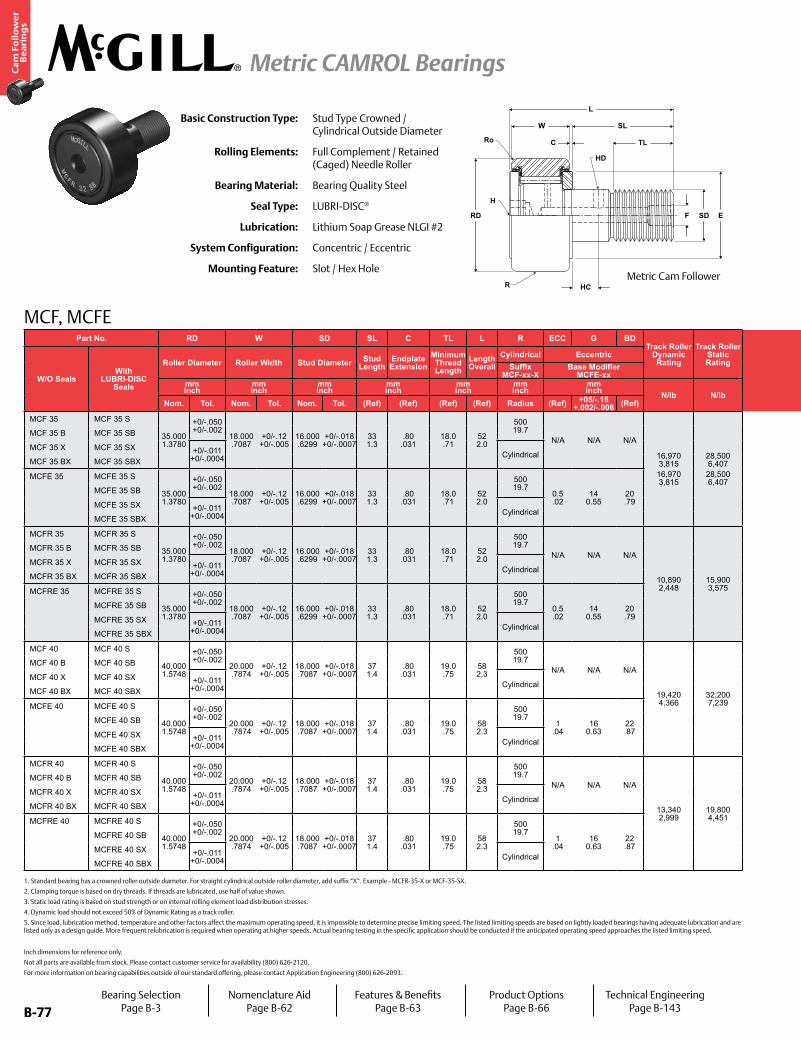
B-77
Ca
m F
oll
ow
er
Be
ari
ng
s
Metric CAMROL Bearings
B-77
MCF, MCFE
Inch dimensions for reference only.
Not all parts are available from stock. Please contact customer service for availability (800) 626-2120.
For more information on bearing capabilities outside of our standard offering, please contact Application Engineering (800) 626-2093.
Basic Construction Type: Stud Type Crowned / Cylindrical Outside Diameter
Rolling Elements: Full Complement / Retained (Caged) Needle Roller
Bearing Material: Bearing Quality Steel
Seal Type: LUBRI-DISC®
Lubrication: Lithium Soap Grease NLGI #2
System Configuration: Concentric / Eccentric
Mounting Feature: Slot / Hex Hole
1. Standard bearing has a crowned roller outside diameter. For straight cylindrical outside roller diameter, add suffix “X”. Example - MCFR-35-X or MCF-35-SX.
2. Clamping torque is based on dry threads. If threads are lubricated, use half of value shown.
3. Static load rating is based on stud strength or on internal rolling element load distribution stresses.
4. Dynamic load should not exceed 50% of Dynamic Rating as a track roller.
5. Since load, lubrication method, temperature and other factors affect the maximum operating speed, it is impossible to determine precise limiting speed. The listed limiting speeds are based on lightly loaded bearings having adequate lubrication and are listed only as a design guide. More frequent relubrication is required when operating at higher speeds. Actual bearing testing in the specific application should be conducted if the anticipated operating speed approaches the listed limiting speed.
Part No. RD W SD SL C TL L R ECC G BDTrack Roller
Dynamic Rating
Track Roller Static Rating
Part No. HC HD F H Ro E Housing Bore
DiameterThread Type
Clamping Torque
Limiting Speed
(Grease)
WT
W/O SealsWith
LUBRI-DISC Seals
Roller Diameter Roller Width Stud Diameter Stud Length
Endplate Extension
Minimum Thread Length
Length Overall
Cylindrical Eccentric
W/O SealsWith
LUBRI-DISC Seals
Hole Center
Radial Lub. Hole
DiameterLub. Hole
DiaHex Hole Outer
CornerMin.
Clamping Diameter
Bearing WeightSuffix
MCF-xx-XBase Modifier
MCFE-xxSuffix
MCF_xx Bmm inch
mm inch
mm inch
mm inch
mm inch
mm inch
mm inch N/lb N/lb
mm inch
mm inch
mm inch
mm inch Nm
in-lb RPM kglbNom. Tol. Nom. Tol. Nom. Tol. (Ref) (Ref) (Ref) (Ref) Radius (Ref) +05/-.15
+.002/-.006 (Ref) (Ref) (Ref) (Ref) (Ref) (Ref) (Ref) Nom. Tol.
MCF 35 MCF 35 S
35.000 1.3780
+0/-.050 +0/-.002
18.000 .7087
+0/-.12 +0/-.005
16.000 .6299
+0/-.018 +0/-.0007
33 1.3
.80 .031
18.0 .71
52 2.0
500 19.7
N/A N/A N/A
16,970 3,81516,970 3,815
28,500 6,407
28,500 6,407
MCF 35 MCF 35 S
8 .315
3 .118
6 .24 N/A
1.0 .04
24 .9
16.000 .6299
+.018/-0 +.0007/- 0 M16x1.5 85
752 4,200 .16 .35
MCF 35 B MCF 35 SB MCF 35 B MCF 35 SB - 8 .31
MCF 35 X MCF 35 SX +0/-.011 +0/-.0004 Cylindrical
MCF 35 X MCF 35 SX 6 .24 N/A
MCF 35 BX MCF 35 SBX MCF 35 BX MCF 35 SBX - 8 .31
MCFE 35 MCFE 35 S
35.000 1.3780
+0/-.050 +0/-.002
18.000 .7087
+0/-.12 +0/-.005
16.000 .6299
+0/-.018 +0/-.0007
33 1.3
.80 .031
18.0 .71
52 2.0
500 19.7
0.5 .02
14 0.55
20 .79
MCFE 35 MCFE 35 S
N/A N/A
6 .24 N/A
1.0 .04
24 .9
20.050 .7894
+0.025/-0 +0.0009/- 0 M16x1.5 85
752 4,200 .16 .35
MCFE 35 SB MCFE 35 SB - 8 .31
MCFE 35 SX +0/-.011 +0/-.0004 Cylindrical
MCFE 35 SX 6 .24 N/A
MCFE 35 SBX MCFE 35 SBX - 8 .31
MCFR 35 MCFR 35 S
35.000 1.3780
+0/-.050 +0/-.002
18.000 .7087
+0/-.12 +0/-.005
16.000 .6299
+0/-.018 +0/-.0007
33 1.3
.80 .031
18.0 .71
52 2.0
500 19.7
N/A N/A N/A
10,890 2,448
15,900 3,575
MCFR 35 MCFR 35 S
8 .315
3 .118
6 .24 N/A
1.0 .04
24 .9
16.000 .6299
+.018/-0 +.0007/- 0 M16x1.5 85
752 6,300 .16 .35
MCFR 35 B MCFR 35 SB MCFR 35 B MCFR 35 SB - 8 .31
MCFR 35 X MCFR 35 SX +0/-.011 +0/-.0004 Cylindrical
MCFR 35 X MCFR 35 SX 6 .24 N/A
MCFR 35 BX MCFR 35 SBX MCFR 35 BX MCFR 35 SBX - 8 .31
MCFRE 35 MCFRE 35 S
35.000 1.3780
+0/-.050 +0/-.002
18.000 .7087
+0/-.12 +0/-.005
16.000 .6299
+0/-.018 +0/-.0007
33 1.3
.80 .031
18.0 .71
52 2.0
500 19.7
0.5 .02
14 0.55
20 .79
MCFRE 35 MCFRE 35 S
N/A N/A
6 .24 N/A
1.0 .04
24 .9
20.050 .7894
+0.025/-0 +0.0009/- 0 M16x1.5 85
752 6,300 .16 .35
MCFRE 35 SB MCFRE 35 SB - 8 .31
MCFRE 35 SX +0/-.011 +0/-.0004 Cylindrical
MCFRE 35 SX 6 .24 N/A
MCFRE 35 SBX MCFRE 35 SBX - 8 .31
MCF 40 MCF 40 S
40.000 1.5748
+0/-.050 +0/-.002
20.000 .7874
+0/-.12 +0/-.005
18.000 .7087
+0/-.018 +0/-.0007
37 1.4
.80 .031
19.0 .75
58 2.3
500 19.7
N/A N/A N/A
19,420 4,366
32,200 7,239
MCF 40 MCF 40 S
8 .315
3 .118
6 .24 N/A
1.5 .06
27 1.1
18.000 .7087
+.018/-0 +.0007/- 0 M18x1.5 85
752 3,300 .25 .55
MCF 40 B MCF 40 SB MCF 40 B MCF 40 SB - 8 .31
MCF 40 X MCF 40 SX +0/-.011 +0/-.0004 Cylindrical
MCF 40 X MCF 40 SX 6 .24 N/A
MCF 40 BX MCF 40 SBX MCF 40 BX MCF 40 SBX - 8 .31
MCFE 40 MCFE 40 S
40.000 1.5748
+0/-.050 +0/-.002
20.000 .7874
+0/-.12 +0/-.005
18.000 .7087
+0/-.018 +0/-.0007
37 1.4
.80 .031
19.0 .75
58 2.3
500 19.7
1 .04
16 0.63
22 .87
MCFE 40 MCFE 40 S
N/A N/A
6 .24 N/A
1.5 .06
27 1.1
22.050 .8681
+0.025/-0 +0.0009/- 0 M18x1.5 85
752 3,300 .25 .55
MCFE 40 SB MCFE 40 SB - 8 .31
MCFE 40 SX +0/-.011 +0/-.0004 Cylindrical
MCFE 40 SX 6 .24 N/A
MCFE 40 SBX MCFE 40 SBX - 8 .31
MCFR 40 MCFR 40 S
40.000 1.5748
+0/-.050 +0/-.002
20.000 .7874
+0/-.12 +0/-.005
18.000 .7087
+0/-.018 +0/-.0007
37 1.4
.80 .031
19.0 .75
58 2.3
500 19.7
N/A N/A N/A
13,340 2,999
19,800 4,451
MCFR 40 MCFR 40 S
8 .315
3 .118
6 .24 N/A
1.5 .06
27 1.1
18.000 .7087
+.018/-0 +.0007/- 0 M18x1.5 85
752 5,000 .25 .55
MCFR 40 B MCFR 40 SB MCFR 40 B MCFR 40 SB - 8 .31
MCFR 40 X MCFR 40 SX +0/-.011 +0/-.0004 Cylindrical
MCFR 40 X MCFR 40 SX 6 .24 N/A
MCFR 40 BX MCFR 40 SBX MCFR 40 BX MCFR 40 SBX - 8 .31
MCFRE 40 MCFRE 40 S
40.000 1.5748
+0/-.050 +0/-.002
20.000 .7874
+0/-.12 +0/-.005
18.000 .7087
+0/-.018 +0/-.0007
37 1.4
.80 .031
19.0 .75
58 2.3
500 19.7
1 .04
16 0.63
22 .87
MCFRE 40 MCFRE 40 S
N/A N/A
6 .24 N/A
1.5 .06
27 1.1
22.050 .8681
+0.025/-0 +0.0009/- 0 M18x1.5 85
752 5,000 .25 .55
MCFRE 40 SB MCFRE 40 SB - 8 .31
MCFRE 40 SX +0/-.011 +0/-.0004 Cylindrical
MCFRE 40 SX 6 .24 N/A
MCFRE 40 SBX MCFRE 40 SBX - 8 .31
W
C
SL
TL
F SD E
HC
RD
H
HD
Ro
L
RMetric Cam Follower
Bearing SelectionPage B-3
Nomenclature AidPage B-62
Features & BenefitsPage B-63
Product OptionsPage B-66
Technical EngineeringPage B-143
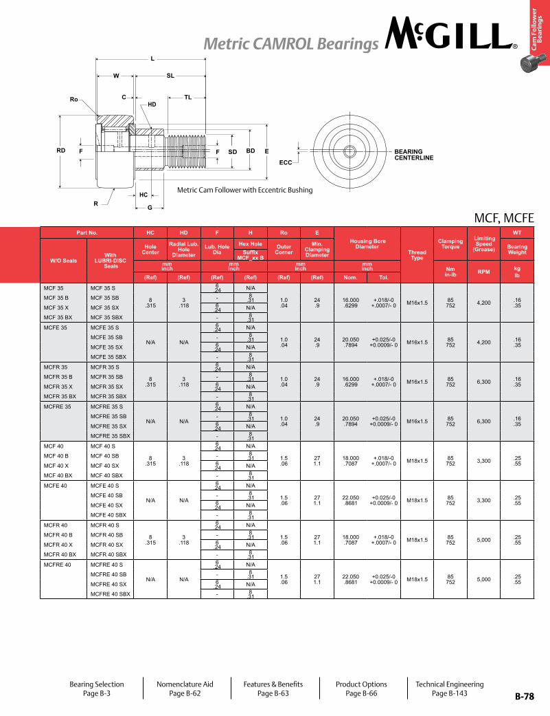
B-78
Ca
m F
oll
ow
er
Be
ari
ng
s
Metric CAMROL Bearings
B-78
MCF, MCFEPart No. RD W SD SL C TL L R ECC G BD
Track Roller Dynamic Rating
Track Roller Static Rating
Part No. HC HD F H Ro E Housing Bore
DiameterThread Type
Clamping Torque
Limiting Speed
(Grease)
WT
W/O SealsWith
LUBRI-DISC Seals
Roller Diameter Roller Width Stud Diameter Stud Length
Endplate Extension
Minimum Thread Length
Length Overall
Cylindrical Eccentric
W/O SealsWith
LUBRI-DISC Seals
Hole Center
Radial Lub. Hole
DiameterLub. Hole
DiaHex Hole Outer
CornerMin.
Clamping Diameter
Bearing WeightSuffix
MCF-xx-XBase Modifier
MCFE-xxSuffix
MCF_xx Bmm inch
mm inch
mm inch
mm inch
mm inch
mm inch
mm inch N/lb N/lb
mm inch
mm inch
mm inch
mm inch Nm
in-lb RPM kglbNom. Tol. Nom. Tol. Nom. Tol. (Ref) (Ref) (Ref) (Ref) Radius (Ref) +05/-.15
+.002/-.006 (Ref) (Ref) (Ref) (Ref) (Ref) (Ref) (Ref) Nom. Tol.
MCF 35 MCF 35 S
35.000 1.3780
+0/-.050 +0/-.002
18.000 .7087
+0/-.12 +0/-.005
16.000 .6299
+0/-.018 +0/-.0007
33 1.3
.80 .031
18.0 .71
52 2.0
500 19.7
N/A N/A N/A
16,970 3,81516,970 3,815
28,500 6,40728,500 6,407
MCF 35 MCF 35 S
8 .315
3 .118
6 .24 N/A
1.0 .04
24 .9
16.000 .6299
+.018/-0 +.0007/- 0 M16x1.5 85
752 4,200 .16 .35
MCF 35 B MCF 35 SB MCF 35 B MCF 35 SB - 8 .31
MCF 35 X MCF 35 SX +0/-.011 +0/-.0004 Cylindrical
MCF 35 X MCF 35 SX 6 .24 N/A
MCF 35 BX MCF 35 SBX MCF 35 BX MCF 35 SBX - 8 .31
MCFE 35 MCFE 35 S
35.000 1.3780
+0/-.050 +0/-.002
18.000 .7087
+0/-.12 +0/-.005
16.000 .6299
+0/-.018 +0/-.0007
33 1.3
.80 .031
18.0 .71
52 2.0
500 19.7
0.5 .02
14 0.55
20 .79
MCFE 35 MCFE 35 S
N/A N/A
6 .24 N/A
1.0 .04
24 .9
20.050 .7894
+0.025/-0 +0.0009/- 0 M16x1.5 85
752 4,200 .16 .35
MCFE 35 SB MCFE 35 SB - 8 .31
MCFE 35 SX +0/-.011 +0/-.0004 Cylindrical
MCFE 35 SX 6 .24 N/A
MCFE 35 SBX MCFE 35 SBX - 8 .31
MCFR 35 MCFR 35 S
35.000 1.3780
+0/-.050 +0/-.002
18.000 .7087
+0/-.12 +0/-.005
16.000 .6299
+0/-.018 +0/-.0007
33 1.3
.80 .031
18.0 .71
52 2.0
500 19.7
N/A N/A N/A
10,890 2,448
15,900 3,575
MCFR 35 MCFR 35 S
8 .315
3 .118
6 .24 N/A
1.0 .04
24 .9
16.000 .6299
+.018/-0 +.0007/- 0 M16x1.5 85
752 6,300 .16 .35
MCFR 35 B MCFR 35 SB MCFR 35 B MCFR 35 SB - 8 .31
MCFR 35 X MCFR 35 SX +0/-.011 +0/-.0004 Cylindrical
MCFR 35 X MCFR 35 SX 6 .24 N/A
MCFR 35 BX MCFR 35 SBX MCFR 35 BX MCFR 35 SBX - 8 .31
MCFRE 35 MCFRE 35 S
35.000 1.3780
+0/-.050 +0/-.002
18.000 .7087
+0/-.12 +0/-.005
16.000 .6299
+0/-.018 +0/-.0007
33 1.3
.80 .031
18.0 .71
52 2.0
500 19.7
0.5 .02
14 0.55
20 .79
MCFRE 35 MCFRE 35 S
N/A N/A
6 .24 N/A
1.0 .04
24 .9
20.050 .7894
+0.025/-0 +0.0009/- 0 M16x1.5 85
752 6,300 .16 .35
MCFRE 35 SB MCFRE 35 SB - 8 .31
MCFRE 35 SX +0/-.011 +0/-.0004 Cylindrical
MCFRE 35 SX 6 .24 N/A
MCFRE 35 SBX MCFRE 35 SBX - 8 .31
MCF 40 MCF 40 S
40.000 1.5748
+0/-.050 +0/-.002
20.000 .7874
+0/-.12 +0/-.005
18.000 .7087
+0/-.018 +0/-.0007
37 1.4
.80 .031
19.0 .75
58 2.3
500 19.7
N/A N/A N/A
19,420 4,366
32,200 7,239
MCF 40 MCF 40 S
8 .315
3 .118
6 .24 N/A
1.5 .06
27 1.1
18.000 .7087
+.018/-0 +.0007/- 0 M18x1.5 85
752 3,300 .25 .55
MCF 40 B MCF 40 SB MCF 40 B MCF 40 SB - 8 .31
MCF 40 X MCF 40 SX +0/-.011 +0/-.0004 Cylindrical
MCF 40 X MCF 40 SX 6 .24 N/A
MCF 40 BX MCF 40 SBX MCF 40 BX MCF 40 SBX - 8 .31
MCFE 40 MCFE 40 S
40.000 1.5748
+0/-.050 +0/-.002
20.000 .7874
+0/-.12 +0/-.005
18.000 .7087
+0/-.018 +0/-.0007
37 1.4
.80 .031
19.0 .75
58 2.3
500 19.7
1 .04
16 0.63
22 .87
MCFE 40 MCFE 40 S
N/A N/A
6 .24 N/A
1.5 .06
27 1.1
22.050 .8681
+0.025/-0 +0.0009/- 0 M18x1.5 85
752 3,300 .25 .55
MCFE 40 SB MCFE 40 SB - 8 .31
MCFE 40 SX +0/-.011 +0/-.0004 Cylindrical
MCFE 40 SX 6 .24 N/A
MCFE 40 SBX MCFE 40 SBX - 8 .31
MCFR 40 MCFR 40 S
40.000 1.5748
+0/-.050 +0/-.002
20.000 .7874
+0/-.12 +0/-.005
18.000 .7087
+0/-.018 +0/-.0007
37 1.4
.80 .031
19.0 .75
58 2.3
500 19.7
N/A N/A N/A
13,340 2,999
19,800 4,451
MCFR 40 MCFR 40 S
8 .315
3 .118
6 .24 N/A
1.5 .06
27 1.1
18.000 .7087
+.018/-0 +.0007/- 0 M18x1.5 85
752 5,000 .25 .55
MCFR 40 B MCFR 40 SB MCFR 40 B MCFR 40 SB - 8 .31
MCFR 40 X MCFR 40 SX +0/-.011 +0/-.0004 Cylindrical
MCFR 40 X MCFR 40 SX 6 .24 N/A
MCFR 40 BX MCFR 40 SBX MCFR 40 BX MCFR 40 SBX - 8 .31
MCFRE 40 MCFRE 40 S
40.000 1.5748
+0/-.050 +0/-.002
20.000 .7874
+0/-.12 +0/-.005
18.000 .7087
+0/-.018 +0/-.0007
37 1.4
.80 .031
19.0 .75
58 2.3
500 19.7
1 .04
16 0.63
22 .87
MCFRE 40 MCFRE 40 S
N/A N/A
6 .24 N/A
1.5 .06
27 1.1
22.050 .8681
+0.025/-0 +0.0009/- 0 M18x1.5 85
752 5,000 .25 .55
MCFRE 40 SB MCFRE 40 SB - 8 .31
MCFRE 40 SX +0/-.011 +0/-.0004 Cylindrical
MCFRE 40 SX 6 .24 N/A
MCFRE 40 SBX MCFRE 40 SBX - 8 .31
Metric Cam Follower with Eccentric Bushing
Bearing SelectionPage B-3
Nomenclature AidPage B-62
Features & BenefitsPage B-63
Product OptionsPage B-66
Technical EngineeringPage B-143
HC
HDRo
SD BEARING CENTERLINE
ECC
RD
C
SL
TL
L
E
GR
F BDF
W
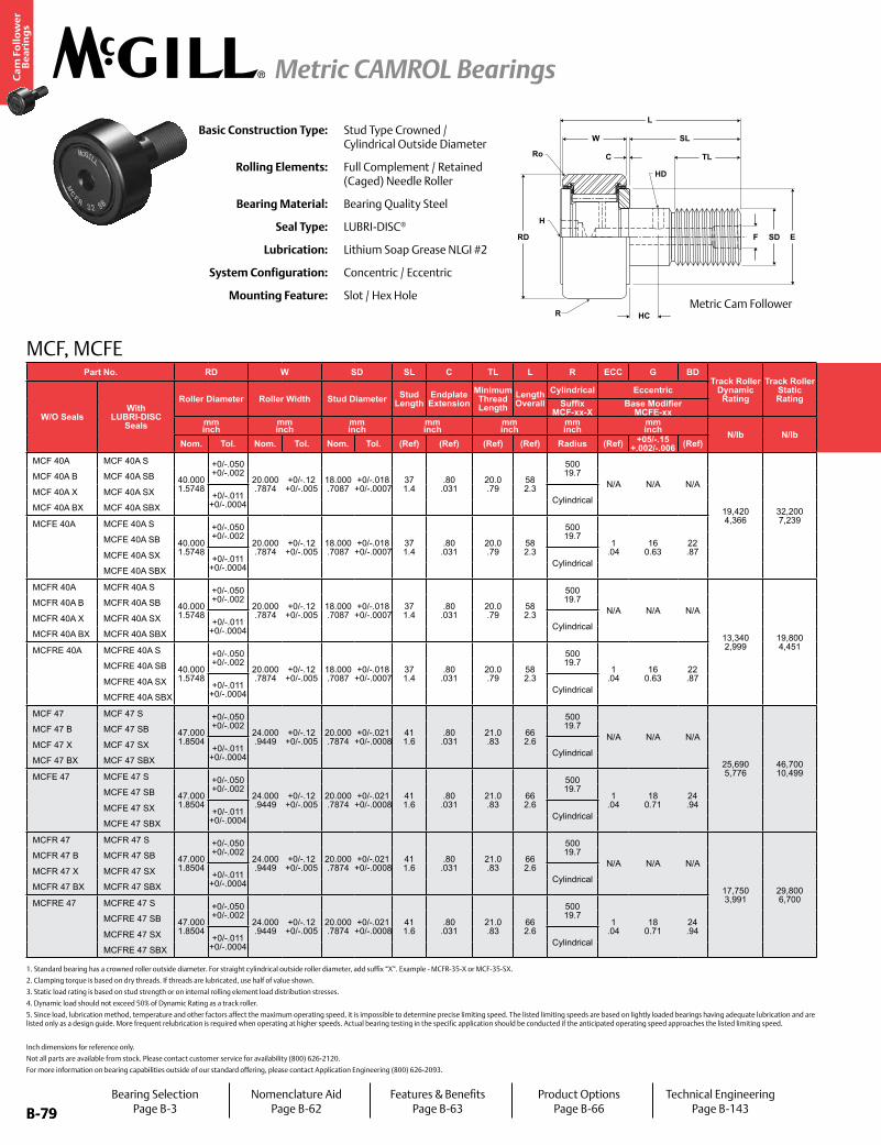
B-79
Ca
m F
oll
ow
er
Be
ari
ng
s
Metric CAMROL Bearings
B-79
MCF, MCFE
Inch dimensions for reference only.
Not all parts are available from stock. Please contact customer service for availability (800) 626-2120.
For more information on bearing capabilities outside of our standard offering, please contact Application Engineering (800) 626-2093.
Basic Construction Type: Stud Type Crowned / Cylindrical Outside Diameter
Rolling Elements: Full Complement / Retained (Caged) Needle Roller
Bearing Material: Bearing Quality Steel
Seal Type: LUBRI-DISC®
Lubrication: Lithium Soap Grease NLGI #2
System Configuration: Concentric / Eccentric
Mounting Feature: Slot / Hex Hole
1. Standard bearing has a crowned roller outside diameter. For straight cylindrical outside roller diameter, add suffix “X”. Example - MCFR-35-X or MCF-35-SX.
2. Clamping torque is based on dry threads. If threads are lubricated, use half of value shown.
3. Static load rating is based on stud strength or on internal rolling element load distribution stresses.
4. Dynamic load should not exceed 50% of Dynamic Rating as a track roller.
5. Since load, lubrication method, temperature and other factors affect the maximum operating speed, it is impossible to determine precise limiting speed. The listed limiting speeds are based on lightly loaded bearings having adequate lubrication and are listed only as a design guide. More frequent relubrication is required when operating at higher speeds. Actual bearing testing in the specific application should be conducted if the anticipated operating speed approaches the listed limiting speed.
Part No. RD W SD SL C TL L R ECC G BDTrack Roller
Dynamic Rating
Track Roller Static Rating
Part No. HC HD F H Ro E Housing Bore
DiameterThread Type
Clamping Torque
Limiting Speed
(Grease)
WT
W/O SealsWith
LUBRI-DISC Seals
Roller Diameter Roller Width Stud Diameter Stud Length
Endplate Extension
Minimum Thread Length
Length Overall
Cylindrical Eccentric
W/O SealsWith
LUBRI-DISC Seals
Hole Center
Radial Lub. Hole
DiameterLub. Hole
DiaHex Hole Outer
CornerMin.
Clamping Diameter
Bearing WeightSuffix
MCF-xx-XBase Modifier
MCFE-xxSuffix
MCF_xx Bmm inch
mm inch
mm inch
mm inch
mm inch
mm inch
mm inch N/lb N/lb
mm inch
mm inch
mm inch
mm inch Nm
in-lb RPM kglbNom. Tol. Nom. Tol. Nom. Tol. (Ref) (Ref) (Ref) (Ref) Radius (Ref) +05/-.15
+.002/-.006 (Ref) (Ref) (Ref) (Ref) (Ref) (Ref) (Ref) Nom. Tol.
MCF 40A MCF 40A S
40.000 1.5748
+0/-.050 +0/-.002
20.000 .7874
+0/-.12 +0/-.005
18.000 .7087
+0/-.018 +0/-.0007
37 1.4
.80 .031
20.0 .79
58 2.3
500 19.7
N/A N/A N/A
19,420 4,366
32,200 7,239
MCF 40A MCF 40A S
10 .394
3 .118
6 .24 N/A
1.5 .06
27 1.1
18.000 .7087
+.018/-0 +.0007/- 0 M18x1.5 118
1,044 3,300 .25 .55
MCF 40A B MCF 40A SB MCF 40A B MCF 40A SB - 8 .31
MCF 40A X MCF 40A SX +0/-.011 +0/-.0004 Cylindrical
MCF 40A X MCF 40A SX 6 .24 N/A
MCF 40A BX MCF 40A SBX MCF 40A BX MCF 40A SBX - 8 .31
MCFE 40A MCFE 40A S
40.000 1.5748
+0/-.050 +0/-.002
20.000 .7874
+0/-.12 +0/-.005
18.000 .7087
+0/-.018 +0/-.0007
37 1.4
.80 .031
20.0 .79
58 2.3
500 19.7
1 .04
16 0.63
22 .87
MCFE 40A MCFE 40A S
N/A N/A
6 .24 N/A
1.5 .06
27 1.1
22.050 .8681
+0.025/-0 +0.0009/- 0 M18x1.5 118
1,044 3,300 .25 .55
MCFE 40A SB MCFE 40A SB - 8 .31
MCFE 40A SX +0/-.011 +0/-.0004 Cylindrical
MCFE 40A SX 6 .24 N/A
MCFE 40A SBX MCFE 40A SBX - 8 .31
MCFR 40A MCFR 40A S
40.000 1.5748
+0/-.050 +0/-.002
20.000 .7874
+0/-.12 +0/-.005
18.000 .7087
+0/-.018 +0/-.0007
37 1.4
.80 .031
20.0 .79
58 2.3
500 19.7
N/A N/A N/A
13,340 2,999
19,800 4,451
MCFR 40A MCFR 40A S
10 .394
3 .118
6 .24 N/A
1.5 .06
27 1.1
18.000 .7087
+.018/-0 +.0007/- 0 M18x1.5 118
1,044 5,000 .25 .55
MCFR 40A B MCFR 40A SB MCFR 40A B MCFR 40A SB - 8 .31
MCFR 40A X MCFR 40A SX +0/-.011 +0/-.0004 Cylindrical
MCFR 40A X MCFR 40A SX 6 .24 N/A
MCFR 40A BX MCFR 40A SBX MCFR 40A BX MCFR 40A SBX - 8 .31
MCFRE 40A MCFRE 40A S
40.000 1.5748
+0/-.050 +0/-.002
20.000 .7874
+0/-.12 +0/-.005
18.000 .7087
+0/-.018 +0/-.0007
37 1.4
.80 .031
20.0 .79
58 2.3
500 19.7
1 .04
16 0.63
22 .87
MCFRE 40A MCFRE 40A S
N/A N/A
6 .24 N/A
1.5 .06
27 1.1
22.050 .8681
+0.025/-0 +0.0009/- 0 M18x1.5 118
1,044 5,000 .25 .55
MCFRE 40A SB MCFRE 40A SB - 8 .31
MCFRE 40A SX +0/-.011 +0/-.0004 Cylindrical
MCFRE 40A SX 6 .24 N/A
MCFRE 40A SBX MCFRE 40A SBX - 8 .31
MCF 47 MCF 47 S
47.000 1.8504
+0/-.050 +0/-.002
24.000 .9449
+0/-.12 +0/-.005
20.000 .7874
+0/-.021 +0/-.0008
41 1.6
.80 .031
21.0 .83
66 2.6
500 19.7
N/A N/A N/A
25,690 5,776
46,700 10,499
MCF 47 MCF 47 S
9 .354
4 .157
8 .31 N/A
1.5 .06
30 1.2
20.000 .7874
+.021/-0 +.0008/- 0 M20x1.5 118
1,044 2,600 .39 .86
MCF 47 B MCF 47 SB MCF 47 B MCF 47 SB - 10 .39
MCF 47 X MCF 47 SX +0/-.011 +0/-.0004 Cylindrical
MCF 47 X MCF 47 SX 8 .31 N/A
MCF 47 BX MCF 47 SBX MCF 47 BX MCF 47 SBX - 10 .39
MCFE 47 MCFE 47 S
47.000 1.8504
+0/-.050 +0/-.002
24.000 .9449
+0/-.12 +0/-.005
20.000 .7874
+0/-.021 +0/-.0008
41 1.6
.80 .031
21.0 .83
66 2.6
500 19.7
1 .04
18 0.71
24 .94
MCFE 47 MCFE 47 S
N/A N/A
8 .31 N/A
1.5 .06
30 1.2
24.050 .9469
+0.025/-0 +0.0009/- 0 M20x1.5 118
1,044 2,600 .39 .86
MCFE 47 SB MCFE 47 SB - 10 .39
MCFE 47 SX +0/-.011 +0/-.0004 Cylindrical
MCFE 47 SX 8 .31 N/A
MCFE 47 SBX MCFE 47 SBX - 10 .39
MCFR 47 MCFR 47 S
47.000 1.8504
+0/-.050 +0/-.002
24.000 .9449
+0/-.12 +0/-.005
20.000 .7874
+0/-.021 +0/-.0008
41 1.6
.80 .031
21.0 .83
66 2.6
500 19.7
N/A N/A N/A
17,750 3,991
29,800 6,700
MCFR 47 MCFR 47 S
9 .354
4 .157
8 .31 N/A
1.5 .06
30 1.2
20.000 .7874
+.021/-0 +.0008/- 0 M20x1.5 118
1,044 3,900 .39 .86
MCFR 47 B MCFR 47 SB MCFR 47 B MCFR 47 SB - 10 .39
MCFR 47 X MCFR 47 SX +0/-.011 +0/-.0004 Cylindrical
MCFR 47 X MCFR 47 SX 8 .31 N/A
MCFR 47 BX MCFR 47 SBX MCFR 47 BX MCFR 47 SBX - 10 .39
MCFRE 47 MCFRE 47 S
47.000 1.8504
+0/-.050 +0/-.002
24.000 .9449
+0/-.12 +0/-.005
20.000 .7874
+0/-.021 +0/-.0008
41 1.6
.80 .031
21.0 .83
66 2.6
500 19.7
1 .04
18 0.71
24 .94
MCFRE 47 MCFRE 47 S
N/A N/A
8 .31 N/A
1.5 .06
30 1.2
24.050 .9469
+0.025/-0 +0.0009/- 0 M20x1.5 118
1,044 3,900 .39 .86
MCFRE 47 SB MCFRE 47 SB - 10 .39
MCFRE 47 SX +0/-.011 +0/-.0004 Cylindrical
MCFRE 47 SX 8 .31 N/A
MCFRE 47 SBX MCFRE 47 SBX - 10 .39
W
C
SL
TL
F SD E
HC
RD
H
HD
Ro
L
RMetric Cam Follower
Bearing SelectionPage B-3
Nomenclature AidPage B-62
Features & BenefitsPage B-63
Product OptionsPage B-66
Technical EngineeringPage B-143

B-80
Ca
m F
oll
ow
er
Be
ari
ng
s
Metric CAMROL Bearings
B-80
MCF, MCFEPart No. RD W SD SL C TL L R ECC G BD
Track Roller Dynamic Rating
Track Roller Static Rating
Part No. HC HD F H Ro E Housing Bore
DiameterThread Type
Clamping Torque
Limiting Speed
(Grease)
WT
W/O SealsWith
LUBRI-DISC Seals
Roller Diameter Roller Width Stud Diameter Stud Length
Endplate Extension
Minimum Thread Length
Length Overall
Cylindrical Eccentric
W/O SealsWith
LUBRI-DISC Seals
Hole Center
Radial Lub. Hole
DiameterLub. Hole
DiaHex Hole Outer
CornerMin.
Clamping Diameter
Bearing WeightSuffix
MCF-xx-XBase Modifier
MCFE-xxSuffix
MCF_xx Bmm inch
mm inch
mm inch
mm inch
mm inch
mm inch
mm inch N/lb N/lb
mm inch
mm inch
mm inch
mm inch Nm
in-lb RPM kglbNom. Tol. Nom. Tol. Nom. Tol. (Ref) (Ref) (Ref) (Ref) Radius (Ref) +05/-.15
+.002/-.006 (Ref) (Ref) (Ref) (Ref) (Ref) (Ref) (Ref) Nom. Tol.
MCF 40A MCF 40A S
40.000 1.5748
+0/-.050 +0/-.002
20.000 .7874
+0/-.12 +0/-.005
18.000 .7087
+0/-.018 +0/-.0007
37 1.4
.80 .031
20.0 .79
58 2.3
500 19.7
N/A N/A N/A
19,420 4,366
32,200 7,239
MCF 40A MCF 40A S
10 .394
3 .118
6 .24 N/A
1.5 .06
27 1.1
18.000 .7087
+.018/-0 +.0007/- 0 M18x1.5 118
1,044 3,300 .25 .55
MCF 40A B MCF 40A SB MCF 40A B MCF 40A SB - 8 .31
MCF 40A X MCF 40A SX +0/-.011 +0/-.0004 Cylindrical
MCF 40A X MCF 40A SX 6 .24 N/A
MCF 40A BX MCF 40A SBX MCF 40A BX MCF 40A SBX - 8 .31
MCFE 40A MCFE 40A S
40.000 1.5748
+0/-.050 +0/-.002
20.000 .7874
+0/-.12 +0/-.005
18.000 .7087
+0/-.018 +0/-.0007
37 1.4
.80 .031
20.0 .79
58 2.3
500 19.7
1 .04
16 0.63
22 .87
MCFE 40A MCFE 40A S
N/A N/A
6 .24 N/A
1.5 .06
27 1.1
22.050 .8681
+0.025/-0 +0.0009/- 0 M18x1.5 118
1,044 3,300 .25 .55
MCFE 40A SB MCFE 40A SB - 8 .31
MCFE 40A SX +0/-.011 +0/-.0004 Cylindrical
MCFE 40A SX 6 .24 N/A
MCFE 40A SBX MCFE 40A SBX - 8 .31
MCFR 40A MCFR 40A S
40.000 1.5748
+0/-.050 +0/-.002
20.000 .7874
+0/-.12 +0/-.005
18.000 .7087
+0/-.018 +0/-.0007
37 1.4
.80 .031
20.0 .79
58 2.3
500 19.7
N/A N/A N/A
13,340 2,999
19,800 4,451
MCFR 40A MCFR 40A S
10 .394
3 .118
6 .24 N/A
1.5 .06
27 1.1
18.000 .7087
+.018/-0 +.0007/- 0 M18x1.5 118
1,044 5,000 .25 .55
MCFR 40A B MCFR 40A SB MCFR 40A B MCFR 40A SB - 8 .31
MCFR 40A X MCFR 40A SX +0/-.011 +0/-.0004 Cylindrical
MCFR 40A X MCFR 40A SX 6 .24 N/A
MCFR 40A BX MCFR 40A SBX MCFR 40A BX MCFR 40A SBX - 8 .31
MCFRE 40A MCFRE 40A S
40.000 1.5748
+0/-.050 +0/-.002
20.000 .7874
+0/-.12 +0/-.005
18.000 .7087
+0/-.018 +0/-.0007
37 1.4
.80 .031
20.0 .79
58 2.3
500 19.7
1 .04
16 0.63
22 .87
MCFRE 40A MCFRE 40A S
N/A N/A
6 .24 N/A
1.5 .06
27 1.1
22.050 .8681
+0.025/-0 +0.0009/- 0 M18x1.5 118
1,044 5,000 .25 .55
MCFRE 40A SB MCFRE 40A SB - 8 .31
MCFRE 40A SX +0/-.011 +0/-.0004 Cylindrical
MCFRE 40A SX 6 .24 N/A
MCFRE 40A SBX MCFRE 40A SBX - 8 .31
MCF 47 MCF 47 S
47.000 1.8504
+0/-.050 +0/-.002
24.000 .9449
+0/-.12 +0/-.005
20.000 .7874
+0/-.021 +0/-.0008
41 1.6
.80 .031
21.0 .83
66 2.6
500 19.7
N/A N/A N/A
25,690 5,776
46,700 10,499
MCF 47 MCF 47 S
9 .354
4 .157
8 .31 N/A
1.5 .06
30 1.2
20.000 .7874
+.021/-0 +.0008/- 0 M20x1.5 118
1,044 2,600 .39 .86
MCF 47 B MCF 47 SB MCF 47 B MCF 47 SB - 10 .39
MCF 47 X MCF 47 SX +0/-.011 +0/-.0004 Cylindrical
MCF 47 X MCF 47 SX 8 .31 N/A
MCF 47 BX MCF 47 SBX MCF 47 BX MCF 47 SBX - 10 .39
MCFE 47 MCFE 47 S
47.000 1.8504
+0/-.050 +0/-.002
24.000 .9449
+0/-.12 +0/-.005
20.000 .7874
+0/-.021 +0/-.0008
41 1.6
.80 .031
21.0 .83
66 2.6
500 19.7
1 .04
18 0.71
24 .94
MCFE 47 MCFE 47 S
N/A N/A
8 .31 N/A
1.5 .06
30 1.2
24.050 .9469
+0.025/-0 +0.0009/- 0 M20x1.5 118
1,044 2,600 .39 .86
MCFE 47 SB MCFE 47 SB - 10 .39
MCFE 47 SX +0/-.011 +0/-.0004 Cylindrical
MCFE 47 SX 8 .31 N/A
MCFE 47 SBX MCFE 47 SBX - 10 .39
MCFR 47 MCFR 47 S
47.000 1.8504
+0/-.050 +0/-.002
24.000 .9449
+0/-.12 +0/-.005
20.000 .7874
+0/-.021 +0/-.0008
41 1.6
.80 .031
21.0 .83
66 2.6
500 19.7
N/A N/A N/A
17,750 3,991
29,800 6,700
MCFR 47 MCFR 47 S
9 .354
4 .157
8 .31 N/A
1.5 .06
30 1.2
20.000 .7874
+.021/-0 +.0008/- 0 M20x1.5 118
1,044 3,900 .39 .86
MCFR 47 B MCFR 47 SB MCFR 47 B MCFR 47 SB - 10 .39
MCFR 47 X MCFR 47 SX +0/-.011 +0/-.0004 Cylindrical
MCFR 47 X MCFR 47 SX 8 .31 N/A
MCFR 47 BX MCFR 47 SBX MCFR 47 BX MCFR 47 SBX - 10 .39
MCFRE 47 MCFRE 47 S
47.000 1.8504
+0/-.050 +0/-.002
24.000 .9449
+0/-.12 +0/-.005
20.000 .7874
+0/-.021 +0/-.0008
41 1.6
.80 .031
21.0 .83
66 2.6
500 19.7
1 .04
18 0.71
24 .94
MCFRE 47 MCFRE 47 S
N/A N/A
8 .31 N/A
1.5 .06
30 1.2
24.050 .9469
+0.025/-0 +0.0009/- 0 M20x1.5 118
1,044 3,900 .39 .86
MCFRE 47 SB MCFRE 47 SB - 10 .39
MCFRE 47 SX +0/-.011 +0/-.0004 Cylindrical
MCFRE 47 SX 8 .31 N/A
MCFRE 47 SBX MCFRE 47 SBX - 10 .39
Metric Cam Follower with Eccentric Bushing
Bearing SelectionPage B-3
Nomenclature AidPage B-62
Features & BenefitsPage B-63
Product OptionsPage B-66
Technical EngineeringPage B-143
HC
HDRo
SD BEARING CENTERLINE
ECC
RD
C
SL
TL
L
E
GR
F BDF
W

B-81
Ca
m F
oll
ow
er
Be
ari
ng
s
Metric CAMROL Bearings
B-81
MCF, MCFE
Inch dimensions for reference only.
Not all parts are available from stock. Please contact customer service for availability (800) 626-2120.
For more information on bearing capabilities outside of our standard offering, please contact Application Engineering (800) 626-2093.
Basic Construction Type: Stud Type Crowned / Cylindrical Outside Diameter
Rolling Elements: Full Complement / Retained (Caged) Needle Roller
Bearing Material: Bearing Quality Steel
Seal Type: LUBRI-DISC®
Lubrication: Lithium Soap Grease NLGI #2
System Configuration: Concentric / Eccentric
Mounting Feature: Slot / Hex Hole
1. Standard bearing has a crowned roller outside diameter. For straight cylindrical outside roller diameter, add suffix “X”. Example - MCFR-35-X or MCF-35-SX.
2. Clamping torque is based on dry threads. If threads are lubricated, use half of value shown.
3. Static load rating is based on stud strength or on internal rolling element load distribution stresses.
4. Dynamic load should not exceed 50% of Dynamic Rating as a track roller.
5. Since load, lubrication method, temperature and other factors affect the maximum operating speed, it is impossible to determine precise limiting speed. The listed limiting speeds are based on lightly loaded bearings having adequate lubrication and are listed only as a design guide. More frequent relubrication is required when operating at higher speeds. Actual bearing testing in the specific application should be conducted if the anticipated operating speed approaches the listed limiting speed.
Part No. RD W SD SL C TL L R ECC G BDTrack Roller
Dynamic Rating
Track Roller Static Rating
Part No. HC HD F H Ro E Housing Bore
DiameterThread Type
Clamping Torque
Limiting Speed
(Grease)
WT
W/O SealsWith
LUBRI-DISC Seals
Roller Diameter Roller Width Stud Diameter Stud Length
Endplate Extension
Minimum Thread Length
Length Overall
Cylindrical Eccentric
W/O SealsWith
LUBRI-DISC Seals
Hole Center
Radial Lub. Hole
DiameterLub. Hole
DiaHex Hole Outer
CornerMin.
Clamping Diameter
Bearing WeightSuffix
MCF-xx-XBase Modifier
MCFE-xxSuffix
MCF_xx Bmm inch
mm inch
mm inch
mm inch
mm inch
mm inch
mm inch N/lb N/lb
mm inch
mm inch
mm inch
mm inch Nm
in-lb RPM kglbNom. Tol. Nom. Tol. Nom. Tol. (Ref) (Ref) (Ref) (Ref) Radius (Ref) +05/-.15
+.002/-.006 (Ref) (Ref) (Ref) (Ref) (Ref) (Ref) (Ref) Nom. Tol.
MCF 47A MCF 47A S
47.000 1.8504
+0/-.050 +0/-.002
24.000 .9449
+0/-.12 +0/-.005
20.000 .7874
+0/-.021 +0/-.0008
41 1.6
.80 .031
22.0 .87
66 2.6
500 19.7
N/A N/A N/A
25,690 5,776
46,700 10,499
MCF 47A MCF 47A S
12 .472
4 .157
8 .31 N/A
1.5 .06
30 1.2
20.000 .7874
+.021/-0 +.0008/- 0 M20x1.5 118
1,044 2,600 .39 .86
MCF 47A B MCF 47A SB MCF 47A B MCF 47A SB - 10 .39
MCF 47A X MCF 47A SX +0/-.011 +0/-.0004 Cylindrical
MCF 47A X MCF 47A SX 8 .31 N/A
MCF 47A BX MCF 47A SBX MCF 47A BX MCF 47A SBX - 10 .39
MCFE 47A MCFE 47A S
47.000 1.8504
+0/-.050 +0/-.002
24.000 .9449
+0/-.12 +0/-.005
20.000 .7874
+0/-.021 +0/-.0008
41 1.6
.80 .031
22.0 .87
66 2.6
500 19.7
1 .04
18 0.71
24 .94
MCFE 47A MCFE 47A S
N/A N/A
8 .31 N/A
1.5 .06
30 1.2
24.050 .9469
+0.025/-0 +0.0009/- 0 M20x1.5 118
1,044 2,600 .39 .86
MCFE 47A SB MCFE 47A SB - 10 .39
MCFE 47A SX +0/-.011 +0/-.0004 Cylindrical
MCFE 47A SX 8 .31 N/A
MCFE 47A SBX MCFE 47A SBX - 10 .39
MCFR 47A MCFR 47A S
47.000 1.8504
+0/-.050 +0/-.002
24.000 .9449
+0/-.12 +0/-.005
20.000 .7874
+0/-.021 +0/-.0008
41 1.6
.80 .031
22.0 .87
66 2.6
500 19.7
N/A N/A N/A
17,750 3,991
29,800 6,700
MCFR 47A MCFR 47A S
12 .472
4 .157
8 .31 N/A
1.5 .06
30 1.2
20.000 .7874
+.021/-0 +.0008/- 0 M20x1.5 118
1,044 3,900 .39 .86
MCFR 47A B MCFR 47A SB MCFR 47A B MCFR 47A SB - 10 .39
MCFR 47A X MCFR 47A SX +0/-.011 +0/-.0004 Cylindrical
MCFR 47A X MCFR 47A SX 8 .31 N/A
MCFR 47A BX MCFR 47A SBX MCFR 47A BX MCFR 47A SBX - 10 .39
MCFRE 47A MCFRE 47A S
47.000 1.8504
+0/-.050 +0/-.002
24.000 .9449
+0/-.12 +0/-.005
20.000 .7874
+0/-.021 +0/-.0008
41 1.6
.80 .031
22.0 .87
66 2.6
500 19.7
1 .04
18 0.71
24 .94
MCFRE 47A MCFRE 47A S
N/A N/A
8 .31 N/A
1.5 .06
30 1.2
24.050 .9469
+0.025/-0 +0.0009/- 0 M20x1.5 118
1,044 3,900 .39 .86
MCFRE 47A SB MCFRE 47A SB - 10 .39
MCFRE 47A SX +0/-.011 +0/-.0004 Cylindrical
MCFRE 47A SX 8 .31 N/A
MCFRE 47A SBX MCFRE 47A SBX - 10 .39
MCF 52 MCF 52 S
52.000 2.0472
+0/-.050 +0/-.002
24.000 .9449
+0/-.12 +0/-.005
20.000 .7874
+0/-.021 +0/-.0008
41 1.6
.80 .031
21.0 .83
66 2.6
500 19.7
N/A N/A N/A
25,690 5,776
46,700 10,499
MCF 52 MCF 52 S
9 .354
4 .157
8 .31 N/A
1.5 .06
36 1.4
20.000 .7874
+.021/-0 +.0008/- 0 M20x1.5 118
1,044 2,600 .45 .99
MCF 52 B MCF 52 SB MCF 52 B MCF 52 SB - 10 .39
MCF 52 X MCF 52 SX +0/-.013 +0/-.0005 Cylindrical
MCF 52 X MCF 52 SX 8 .31 N/A
MCF 52 BX MCF 52 SBX MCF 52 BX MCF 52 SBX - 10 .39
MCFE 52 MCFE 52 S
52.000 2.0472
+0/-.050 +0/-.002
24.000 .9449
+0/-.12 +0/-.005
20.000 .7874
+0/-.021 +0/-.0008
41 1.6
.80 .031
21.0 .83
66 2.6
500 19.7
1 .04
18 0.71
24 .94
MCFE 52 MCFE 52 S
N/A N/A
8 .31 N/A
1.5 .06
36 1.4
24.050 .9469
+0.025/-0 +0.0009/- 0 M20x1.5 118
1,044 2,600 .45 .99
MCFE 52 SB MCFE 52 SB - 10 .39
MCFE 52 SX +0/-.013 +0/-.0005 Cylindrical
MCFE 52 SX 8 .31 N/A
MCFE 52 SBX MCFE 52 SBX - 10 .39
MCFR 52 MCFR 52 S
52.000 2.0472
+0/-.050 +0/-.002
24.000 .9449
+0/-.12 +0/-.005
20.000 .7874
+0/-.021 +0/-.0008
41 1.6
.80 .031
21.0 .83
66 2.6
500 19.7
N/A N/A N/A
17,750 3,991
29,800 6,700
MCFR 52 MCFR 52 S
9 .354
4 .157
8 .31 N/A
1.5 .06
36 1.4
20.000 .7874
+.021/-0 +.0008/- 0 M20x1.5 118
1,044 3,900 .45 .99
MCFR 52 B MCFR 52 SB MCFR 52 B MCFR 52 SB - 10 .39
MCFR 52 X MCFR 52 SX +0/-.013 +0/-.0005 Cylindrical
MCFR 52 X MCFR 52 SX 8 .31 N/A
MCFR 52 BX MCFR 52 SBX MCFR 52 BX MCFR 52 SBX - 10 .39
MCFRE 52 MCFRE 52 S
52.000 2.0472
+0/-.050 +0/-.002
24.000 .9449
+0/-.12 +0/-.005
20.000 .7874
+0/-.021 +0/-.0008
41 1.6
.80 .031
21.0 .83
66 2.6
500 19.7
1 .04
18 0.71
24 .94
MCFRE 52 MCFRE 52 S
N/A N/A
8 .31 N/A
1.5 .06
36 1.4
24.050 .9469
+0.025/-0 +0.0009/- 0 M20x1.5 118
1,044 3,900 .45 .99
MCFRE 52 SB MCFRE 52 SB - 10 .39
MCFRE 52 SX +0/-.013 +0/-.0005 Cylindrical
MCFRE 52 SX 8 .31 N/A
MCFRE 52 SBX MCFRE 52 SBX - 10 .39
W
C
SL
TL
F SD E
HC
RD
H
HD
Ro
L
RMetric Cam Follower
Bearing SelectionPage B-3
Nomenclature AidPage B-62
Features & BenefitsPage B-63
Product OptionsPage B-66
Technical EngineeringPage B-143

B-82
Ca
m F
oll
ow
er
Be
ari
ng
s
Metric CAMROL Bearings
B-82
MCF, MCFEPart No. RD W SD SL C TL L R ECC G BD
Track Roller Dynamic Rating
Track Roller Static Rating
Part No. HC HD F H Ro E Housing Bore
DiameterThread Type
Clamping Torque
Limiting Speed
(Grease)
WT
W/O SealsWith
LUBRI-DISC Seals
Roller Diameter Roller Width Stud Diameter Stud Length
Endplate Extension
Minimum Thread Length
Length Overall
Cylindrical Eccentric
W/O SealsWith
LUBRI-DISC Seals
Hole Center
Radial Lub. Hole
DiameterLub. Hole
DiaHex Hole Outer
CornerMin.
Clamping Diameter
Bearing WeightSuffix
MCF-xx-XBase Modifier
MCFE-xxSuffix
MCF_xx Bmm inch
mm inch
mm inch
mm inch
mm inch
mm inch
mm inch N/lb N/lb
mm inch
mm inch
mm inch
mm inch Nm
in-lb RPM kglbNom. Tol. Nom. Tol. Nom. Tol. (Ref) (Ref) (Ref) (Ref) Radius (Ref) +05/-.15
+.002/-.006 (Ref) (Ref) (Ref) (Ref) (Ref) (Ref) (Ref) Nom. Tol.
MCF 47A MCF 47A S
47.000 1.8504
+0/-.050 +0/-.002
24.000 .9449
+0/-.12 +0/-.005
20.000 .7874
+0/-.021 +0/-.0008
41 1.6
.80 .031
22.0 .87
66 2.6
500 19.7
N/A N/A N/A
25,690 5,776
46,700 10,499
MCF 47A MCF 47A S
12 .472
4 .157
8 .31 N/A
1.5 .06
30 1.2
20.000 .7874
+.021/-0 +.0008/- 0 M20x1.5 118
1,044 2,600 .39 .86
MCF 47A B MCF 47A SB MCF 47A B MCF 47A SB - 10 .39
MCF 47A X MCF 47A SX +0/-.011 +0/-.0004 Cylindrical
MCF 47A X MCF 47A SX 8 .31 N/A
MCF 47A BX MCF 47A SBX MCF 47A BX MCF 47A SBX - 10 .39
MCFE 47A MCFE 47A S
47.000 1.8504
+0/-.050 +0/-.002
24.000 .9449
+0/-.12 +0/-.005
20.000 .7874
+0/-.021 +0/-.0008
41 1.6
.80 .031
22.0 .87
66 2.6
500 19.7
1 .04
18 0.71
24 .94
MCFE 47A MCFE 47A S
N/A N/A
8 .31 N/A
1.5 .06
30 1.2
24.050 .9469
+0.025/-0 +0.0009/- 0 M20x1.5 118
1,044 2,600 .39 .86
MCFE 47A SB MCFE 47A SB - 10 .39
MCFE 47A SX +0/-.011 +0/-.0004 Cylindrical
MCFE 47A SX 8 .31 N/A
MCFE 47A SBX MCFE 47A SBX - 10 .39
MCFR 47A MCFR 47A S
47.000 1.8504
+0/-.050 +0/-.002
24.000 .9449
+0/-.12 +0/-.005
20.000 .7874
+0/-.021 +0/-.0008
41 1.6
.80 .031
22.0 .87
66 2.6
500 19.7
N/A N/A N/A
17,750 3,991
29,800 6,700
MCFR 47A MCFR 47A S
12 .472
4 .157
8 .31 N/A
1.5 .06
30 1.2
20.000 .7874
+.021/-0 +.0008/- 0 M20x1.5 118
1,044 3,900 .39 .86
MCFR 47A B MCFR 47A SB MCFR 47A B MCFR 47A SB - 10 .39
MCFR 47A X MCFR 47A SX +0/-.011 +0/-.0004 Cylindrical
MCFR 47A X MCFR 47A SX 8 .31 N/A
MCFR 47A BX MCFR 47A SBX MCFR 47A BX MCFR 47A SBX - 10 .39
MCFRE 47A MCFRE 47A S
47.000 1.8504
+0/-.050 +0/-.002
24.000 .9449
+0/-.12 +0/-.005
20.000 .7874
+0/-.021 +0/-.0008
41 1.6
.80 .031
22.0 .87
66 2.6
500 19.7
1 .04
18 0.71
24 .94
MCFRE 47A MCFRE 47A S
N/A N/A
8 .31 N/A
1.5 .06
30 1.2
24.050 .9469
+0.025/-0 +0.0009/- 0 M20x1.5 118
1,044 3,900 .39 .86
MCFRE 47A SB MCFRE 47A SB - 10 .39
MCFRE 47A SX +0/-.011 +0/-.0004 Cylindrical
MCFRE 47A SX 8 .31 N/A
MCFRE 47A SBX MCFRE 47A SBX - 10 .39
MCF 52 MCF 52 S
52.000 2.0472
+0/-.050 +0/-.002
24.000 .9449
+0/-.12 +0/-.005
20.000 .7874
+0/-.021 +0/-.0008
41 1.6
.80 .031
21.0 .83
66 2.6
500 19.7
N/A N/A N/A
25,690 5,776
46,700 10,499
MCF 52 MCF 52 S
9 .354
4 .157
8 .31 N/A
1.5 .06
36 1.4
20.000 .7874
+.021/-0 +.0008/- 0 M20x1.5 118
1,044 2,600 .45 .99
MCF 52 B MCF 52 SB MCF 52 B MCF 52 SB - 10 .39
MCF 52 X MCF 52 SX +0/-.013 +0/-.0005 Cylindrical
MCF 52 X MCF 52 SX 8 .31 N/A
MCF 52 BX MCF 52 SBX MCF 52 BX MCF 52 SBX - 10 .39
MCFE 52 MCFE 52 S
52.000 2.0472
+0/-.050 +0/-.002
24.000 .9449
+0/-.12 +0/-.005
20.000 .7874
+0/-.021 +0/-.0008
41 1.6
.80 .031
21.0 .83
66 2.6
500 19.7
1 .04
18 0.71
24 .94
MCFE 52 MCFE 52 S
N/A N/A
8 .31 N/A
1.5 .06
36 1.4
24.050 .9469
+0.025/-0 +0.0009/- 0 M20x1.5 118
1,044 2,600 .45 .99
MCFE 52 SB MCFE 52 SB - 10 .39
MCFE 52 SX +0/-.013 +0/-.0005 Cylindrical
MCFE 52 SX 8 .31 N/A
MCFE 52 SBX MCFE 52 SBX - 10 .39
MCFR 52 MCFR 52 S
52.000 2.0472
+0/-.050 +0/-.002
24.000 .9449
+0/-.12 +0/-.005
20.000 .7874
+0/-.021 +0/-.0008
41 1.6
.80 .031
21.0 .83
66 2.6
500 19.7
N/A N/A N/A
17,750 3,991
29,800 6,700
MCFR 52 MCFR 52 S
9 .354
4 .157
8 .31 N/A
1.5 .06
36 1.4
20.000 .7874
+.021/-0 +.0008/- 0 M20x1.5 118
1,044 3,900 .45 .99
MCFR 52 B MCFR 52 SB MCFR 52 B MCFR 52 SB - 10 .39
MCFR 52 X MCFR 52 SX +0/-.013 +0/-.0005 Cylindrical
MCFR 52 X MCFR 52 SX 8 .31 N/A
MCFR 52 BX MCFR 52 SBX MCFR 52 BX MCFR 52 SBX - 10 .39
MCFRE 52 MCFRE 52 S
52.000 2.0472
+0/-.050 +0/-.002
24.000 .9449
+0/-.12 +0/-.005
20.000 .7874
+0/-.021 +0/-.0008
41 1.6
.80 .031
21.0 .83
66 2.6
500 19.7
1 .04
18 0.71
24 .94
MCFRE 52 MCFRE 52 S
N/A N/A
8 .31 N/A
1.5 .06
36 1.4
24.050 .9469
+0.025/-0 +0.0009/- 0 M20x1.5 118
1,044 3,900 .45 .99
MCFRE 52 SB MCFRE 52 SB - 10 .39
MCFRE 52 SX +0/-.013 +0/-.0005 Cylindrical
MCFRE 52 SX 8 .31 N/A
MCFRE 52 SBX MCFRE 52 SBX - 10 .39
Metric Cam Follower with Eccentric Bushing
Bearing SelectionPage B-3
Nomenclature AidPage B-62
Features & BenefitsPage B-63
Product OptionsPage B-66
Technical EngineeringPage B-143
HC
HDRo
SD BEARING CENTERLINE
ECC
RD
C
SL
TL
L
E
GR
F BDF
W

B-83
Ca
m F
oll
ow
er
Be
ari
ng
s
Metric CAMROL Bearings
B-83
MCF, MCFE
Inch dimensions for reference only.
Not all parts are available from stock. Please contact customer service for availability (800) 626-2120.
For more information on bearing capabilities outside of our standard offering, please contact Application Engineering (800) 626-2093.
Basic Construction Type: Stud Type Crowned / Cylindrical Outside Diameter
Rolling Elements: Full Complement / Retained (Caged) Needle Roller
Bearing Material: Bearing Quality Steel
Seal Type: LUBRI-DISC®
Lubrication: Lithium Soap Grease NLGI #2
System Configuration: Concentric / Eccentric
Mounting Feature: Slot / Hex Hole
1. Standard bearing has a crowned roller outside diameter. For straight cylindrical outside roller diameter, add suffix “X”. Example - MCFR-35-X or MCF-35-SX.
2. Clamping torque is based on dry threads. If threads are lubricated, use half of value shown.
3. Static load rating is based on stud strength or on internal rolling element load distribution stresses.
4. Dynamic load should not exceed 50% of Dynamic Rating as a track roller.
5. Since load, lubrication method, temperature and other factors affect the maximum operating speed, it is impossible to determine precise limiting speed. The listed limiting speeds are based on lightly loaded bearings having adequate lubrication and are listed only as a design guide. More frequent relubrication is required when operating at higher speeds. Actual bearing testing in the specific application should be conducted if the anticipated operating speed approaches the listed limiting speed.
Part No. RD W SD SL C TL L R ECC G BDTrack Roller
Dynamic Rating
Track Roller Static Rating
Part No. HC HD F H Ro E Housing Bore
DiameterThread Type
Clamping Torque
Limiting Speed
(Grease)
WT
W/O SealsWith
LUBRI-DISC Seals
Roller Diameter Roller Width Stud Diameter Stud Length
Endplate Extension
Minimum Thread Length
Length Overall
Cylindrical Eccentric
W/O SealsWith
LUBRI-DISC Seals
Hole Center
Radial Lub. Hole
DiameterLub. Hole
DiaHex Hole Outer
CornerMin.
Clamping Diameter
Bearing WeightSuffix
MCF-xx-XBase Modifier
MCFE-xxSuffix
MCF_xx Bmm inch
mm inch
mm inch
mm inch
mm inch
mm inch
mm inch N/lb N/lb
mm inch
mm inch
mm inch
mm inch Nm
in-lb RPM kglbNom. Tol. Nom. Tol. Nom. Tol. (Ref) (Ref) (Ref) (Ref) Radius (Ref) +05/-.15
+.002/-.006 (Ref) (Ref) (Ref) (Ref) (Ref) (Ref) (Ref) Nom. Tol.
MCF 52A MCF 52A S
52.000 2.0472
+0/-.050 +0/-.002
24.000 .9449
+0/-.12 +0/-.005
20.000 .7874
+0/-.021 +0/-.0008
41 1.6
.80 .031
22.0 .87
66 2.6
500 19.7
N/A N/A N/A
25,690 5,776
46,700 10,499
MCF 52A MCF 52A S
12 .472
4 .157
8 .31 N/A
1.5 .06
36 1.4
20.000 .7874
+.021/-0 +.0008/- 0 M20x1.5 216
1,912 2,600 .45 .99
MCF 52A B MCF 52A SB MCF 52A B MCF 52A SB - 10 .39
MCF 52A X MCF 52A SX +0/-.013 +0/-.0005 Cylindrical
MCF 52A X MCF 52A SX 8 .31 N/A
MCF 52A BX MCF 52A SBX MCF 52A BX MCF 52A SBX - 10 .39
MCFE 52A MCFE 52A S
52.000 2.0472
+0/-.050 +0/-.002
24.000 .9449
+0/-.12 +0/-.005
20.000 .7874
+0/-.021 +0/-.0008
41 1.6
.80 .031
22.0 .87
66 2.6
500 19.7
1 .04
18 0.71
24 .94
MCFE 52A MCFE 52A S
N/A N/A
8 .31 N/A
1.5 .06
36 1.4
24.050 .9469
+0.025/-0 +0.0009/- 0 M20x1.5 216
1,912 2,600 .45 .99
MCFE 52A SB MCFE 52A SB - 10 .39
MCFE 52A SX +0/-.013 +0/-.0005 Cylindrical
MCFE 52A SX 8 .31 N/A
MCFE 52A SBX MCFE 52A SBX - 10 .39
MCFR 52A MCFR 52A S
52.000 2.0472
+0/-.050 +0/-.002
24.000 .9449
+0/-.12 +0/-.005
20.000 .7874
+0/-.021 +0/-.0008
41 1.6
.80 .031
22.0 .87
66 2.6
500 19.7
N/A N/A N/A
17,750 3,991
29,800 6,700
MCFR 52A MCFR 52A S
12 .472
4 .157
8 .31 N/A
1.5 .06
36 1.4
20.000 .7874
+.021/-0 +.0008/- 0 M20x1.5 216
1,912 3,900 .45 .99
MCFR 52A B MCFR 52A SB MCFR 52A B MCFR 52A SB - 10 .39
MCFR 52A X MCFR 52A SX +0/-.013 +0/-.0005 Cylindrical
MCFR 52A X MCFR 52A SX 8 .31 N/A
MCFR 52A BX MCFR 52A SBX MCFR 52A BX MCFR 52A SBX - 10 .39
MCFRE 52A MCFRE 52A S
52.000 2.0472
+0/-.050 +0/-.002
24.000 .9449
+0/-.12 +0/-.005
20.000 .7874
+0/-.021 +0/-.0008
41 1.6
.80 .031
22.0 .87
66 2.6
500 19.7
1 .04
18 0.71
24 .94
MCFRE 52A MCFRE 52A S
N/A N/A
8 .31 N/A
1.5 .06
36 1.4
24.050 .9469
+0.025/-0 +0.0009/- 0 M20x1.5 216
1,912 3,900 .45 .99
MCFRE 52A SB MCFRE 52A SB - 10 .39
MCFRE 52A SX +0/-.013 +0/-.0005 Cylindrical
MCFRE 52A SX 8 .31 N/A
MCFRE 52A SBX MCFRE 52A SBX - 10 .39
MCF 62 MCF 62 S
62.000 2.4409
+0/-.050 +0/-.002
29.000 1.1417
+0/-.12 +0/-.005
24.000 .9449
+0/-.021 +0/-.0008
50 1.9
.80 .031
25.0 .98
80 3.1
500 19.7
N/A N/A N/A
38,840 8,732
65,400 14,703
MCF 62 MCF 62 S
11 .433
4 .157
8 .31 N/A
2.0 .08
44 1.7
24.000 .9449
+.021/-0 +.0008/- 0 M24x1.5 216
1,912 2,100 .81 1.79
MCF 62 B MCF 62 SB MCF 62 B MCF 62 SB - 14 .55
MCF 62 X MCF 62 SX +0/-.013 +0/-.0005 Cylindrical
MCF 62 X MCF 62 SX 8 .31 N/A
MCF 62 BX MCF 62 SBX MCF 62 BX MCF 62 SBX - 14 .55
MCFE 62 MCFE 62 S
62.000 2.4409
+0/-.050 +0/-.002
29.000 1.1417
+0/-.12 +0/-.005
24.000 .9449
+0/-.021 +0/-.0008
50 1.9
.80 .031
25.0 .98
80 3.1
500 19.7
1 .04
22 0.87
28 .10
MCFE 62 MCFE 62 S
N/A N/A
8 .31 N/A
2.0 .08
63 2.5
28.050 .1043
+0.025/-0 +0.0009/- 0 M24x1.5 216
1,912 2,100 .81 1.79
MCFE 62 SB MCFE 62 SB - 14 .55
MCFE 62 SX +0/-.013 +0/-.0005 Cylindrical
MCFE 62 SX 8 .31 N/A
MCFE 62 SBX MCFE 62 SBX - 14 .55
MCFR 62 MCFR 62 S
62.000 2.4409
+0/-.050 +0/-.002
29.000 1.1417
+0/-.12 +0/-.005
24.000 .9449
+0/-.021 +0/-.0008
50 1.9
.80 .031
25.0 .98
80 3.1
500 19.7
N/A N/A N/A
26,380 5,931
46,300 10,409
MCFR 62 MCFR 62 S
11 .433
4 .157
8 .31 N/A
2.0 .08
63 2.5
24.000 .9449
+.021/-0 +.0008/- 0 M24x1.5 216
1,912 3,100 .81 1.79
MCFR 62 B MCFR 62 SB MCFR 62 B MCFR 62 SB - 14 .55
MCFR 62 X MCFR 62 SX +0/-.013 +0/-.0005 Cylindrical
MCFR 62 X MCFR 62 SX 8 .31 N/A
MCFR 62 BX MCFR 62 SBX MCFR 62 BX MCFR 62 SBX - 14 .55
MCFRE 62 MCFRE 62 S
62.000 2.4409
+0/-.050 +0/-.002
29.000 1.1417
+0/-.12 +0/-.005
24.000 .9449
+0/-.021 +0/-.0008
50 1.9
.80 .031
25.0 .98
80 3.1
500 19.7
1 .04
22 0.87
28 .10
MCFRE 62 MCFRE 62 S
N/A N/A
8 .31 N/A
2.0 .08
63 2.5
28.050 .1043
+0.025/-0 +0.0009/- 0 M24x1.5 216
1,912 3,100 .81 1.79
MCFRE 62 SB MCFRE 62 SB - 14 .55
MCFRE 62 SX +0/-.013 +0/-.0005 Cylindrical
MCFRE 62 SX 8 .31 N/A
MCFRE 62 SBX MCFRE 62 SBX - 14 .55
W
C
SL
TL
F SD E
HC
RD
H
HD
Ro
L
RMetric Cam Follower
Bearing SelectionPage B-3
Nomenclature AidPage B-62
Features & BenefitsPage B-63
Product OptionsPage B-66
Technical EngineeringPage B-143

B-84
Ca
m F
oll
ow
er
Be
ari
ng
s
Metric CAMROL Bearings
B-84
MCF, MCFEPart No. RD W SD SL C TL L R ECC G BD
Track Roller Dynamic Rating
Track Roller Static Rating
Part No. HC HD F H Ro E Housing Bore
DiameterThread Type
Clamping Torque
Limiting Speed
(Grease)
WT
W/O SealsWith
LUBRI-DISC Seals
Roller Diameter Roller Width Stud Diameter Stud Length
Endplate Extension
Minimum Thread Length
Length Overall
Cylindrical Eccentric
W/O SealsWith
LUBRI-DISC Seals
Hole Center
Radial Lub. Hole
DiameterLub. Hole
DiaHex Hole Outer
CornerMin.
Clamping Diameter
Bearing WeightSuffix
MCF-xx-XBase Modifier
MCFE-xxSuffix
MCF_xx Bmm inch
mm inch
mm inch
mm inch
mm inch
mm inch
mm inch N/lb N/lb
mm inch
mm inch
mm inch
mm inch Nm
in-lb RPM kglbNom. Tol. Nom. Tol. Nom. Tol. (Ref) (Ref) (Ref) (Ref) Radius (Ref) +05/-.15
+.002/-.006 (Ref) (Ref) (Ref) (Ref) (Ref) (Ref) (Ref) Nom. Tol.
MCF 52A MCF 52A S
52.000 2.0472
+0/-.050 +0/-.002
24.000 .9449
+0/-.12 +0/-.005
20.000 .7874
+0/-.021 +0/-.0008
41 1.6
.80 .031
22.0 .87
66 2.6
500 19.7
N/A N/A N/A
25,690 5,776
46,700 10,499
MCF 52A MCF 52A S
12 .472
4 .157
8 .31 N/A
1.5 .06
36 1.4
20.000 .7874
+.021/-0 +.0008/- 0 M20x1.5 216
1,912 2,600 .45 .99
MCF 52A B MCF 52A SB MCF 52A B MCF 52A SB - 10 .39
MCF 52A X MCF 52A SX +0/-.013 +0/-.0005 Cylindrical
MCF 52A X MCF 52A SX 8 .31 N/A
MCF 52A BX MCF 52A SBX MCF 52A BX MCF 52A SBX - 10 .39
MCFE 52A MCFE 52A S
52.000 2.0472
+0/-.050 +0/-.002
24.000 .9449
+0/-.12 +0/-.005
20.000 .7874
+0/-.021 +0/-.0008
41 1.6
.80 .031
22.0 .87
66 2.6
500 19.7
1 .04
18 0.71
24 .94
MCFE 52A MCFE 52A S
N/A N/A
8 .31 N/A
1.5 .06
36 1.4
24.050 .9469
+0.025/-0 +0.0009/- 0 M20x1.5 216
1,912 2,600 .45 .99
MCFE 52A SB MCFE 52A SB - 10 .39
MCFE 52A SX +0/-.013 +0/-.0005 Cylindrical
MCFE 52A SX 8 .31 N/A
MCFE 52A SBX MCFE 52A SBX - 10 .39
MCFR 52A MCFR 52A S
52.000 2.0472
+0/-.050 +0/-.002
24.000 .9449
+0/-.12 +0/-.005
20.000 .7874
+0/-.021 +0/-.0008
41 1.6
.80 .031
22.0 .87
66 2.6
500 19.7
N/A N/A N/A
17,750 3,991
29,800 6,700
MCFR 52A MCFR 52A S
12 .472
4 .157
8 .31 N/A
1.5 .06
36 1.4
20.000 .7874
+.021/-0 +.0008/- 0 M20x1.5 216
1,912 3,900 .45 .99
MCFR 52A B MCFR 52A SB MCFR 52A B MCFR 52A SB - 10 .39
MCFR 52A X MCFR 52A SX +0/-.013 +0/-.0005 Cylindrical
MCFR 52A X MCFR 52A SX 8 .31 N/A
MCFR 52A BX MCFR 52A SBX MCFR 52A BX MCFR 52A SBX - 10 .39
MCFRE 52A MCFRE 52A S
52.000 2.0472
+0/-.050 +0/-.002
24.000 .9449
+0/-.12 +0/-.005
20.000 .7874
+0/-.021 +0/-.0008
41 1.6
.80 .031
22.0 .87
66 2.6
500 19.7
1 .04
18 0.71
24 .94
MCFRE 52A MCFRE 52A S
N/A N/A
8 .31 N/A
1.5 .06
36 1.4
24.050 .9469
+0.025/-0 +0.0009/- 0 M20x1.5 216
1,912 3,900 .45 .99
MCFRE 52A SB MCFRE 52A SB - 10 .39
MCFRE 52A SX +0/-.013 +0/-.0005 Cylindrical
MCFRE 52A SX 8 .31 N/A
MCFRE 52A SBX MCFRE 52A SBX - 10 .39
MCF 62 MCF 62 S
62.000 2.4409
+0/-.050 +0/-.002
29.000 1.1417
+0/-.12 +0/-.005
24.000 .9449
+0/-.021 +0/-.0008
50 1.9
.80 .031
25.0 .98
80 3.1
500 19.7
N/A N/A N/A
38,840 8,732
65,400 14,703
MCF 62 MCF 62 S
11 .433
4 .157
8 .31 N/A
2.0 .08
44 1.7
24.000 .9449
+.021/-0 +.0008/- 0 M24x1.5 216
1,912 2,100 .81 1.79
MCF 62 B MCF 62 SB MCF 62 B MCF 62 SB - 14 .55
MCF 62 X MCF 62 SX +0/-.013 +0/-.0005 Cylindrical
MCF 62 X MCF 62 SX 8 .31 N/A
MCF 62 BX MCF 62 SBX MCF 62 BX MCF 62 SBX - 14 .55
MCFE 62 MCFE 62 S
62.000 2.4409
+0/-.050 +0/-.002
29.000 1.1417
+0/-.12 +0/-.005
24.000 .9449
+0/-.021 +0/-.0008
50 1.9
.80 .031
25.0 .98
80 3.1
500 19.7
1 .04
22 0.87
28 .10
MCFE 62 MCFE 62 S
N/A N/A
8 .31 N/A
2.0 .08
63 2.5
28.050 .1043
+0.025/-0 +0.0009/- 0 M24x1.5 216
1,912 2,100 .81 1.79
MCFE 62 SB MCFE 62 SB - 14 .55
MCFE 62 SX +0/-.013 +0/-.0005 Cylindrical
MCFE 62 SX 8 .31 N/A
MCFE 62 SBX MCFE 62 SBX - 14 .55
MCFR 62 MCFR 62 S
62.000 2.4409
+0/-.050 +0/-.002
29.000 1.1417
+0/-.12 +0/-.005
24.000 .9449
+0/-.021 +0/-.0008
50 1.9
.80 .031
25.0 .98
80 3.1
500 19.7
N/A N/A N/A
26,380 5,931
46,300 10,409
MCFR 62 MCFR 62 S
11 .433
4 .157
8 .31 N/A
2.0 .08
63 2.5
24.000 .9449
+.021/-0 +.0008/- 0 M24x1.5 216
1,912 3,100 .81 1.79
MCFR 62 B MCFR 62 SB MCFR 62 B MCFR 62 SB - 14 .55
MCFR 62 X MCFR 62 SX +0/-.013 +0/-.0005 Cylindrical
MCFR 62 X MCFR 62 SX 8 .31 N/A
MCFR 62 BX MCFR 62 SBX MCFR 62 BX MCFR 62 SBX - 14 .55
MCFRE 62 MCFRE 62 S
62.000 2.4409
+0/-.050 +0/-.002
29.000 1.1417
+0/-.12 +0/-.005
24.000 .9449
+0/-.021 +0/-.0008
50 1.9
.80 .031
25.0 .98
80 3.1
500 19.7
1 .04
22 0.87
28 .10
MCFRE 62 MCFRE 62 S
N/A N/A
8 .31 N/A
2.0 .08
63 2.5
28.050 .1043
+0.025/-0 +0.0009/- 0 M24x1.5 216
1,912 3,100 .81 1.79
MCFRE 62 SB MCFRE 62 SB - 14 .55
MCFRE 62 SX +0/-.013 +0/-.0005 Cylindrical
MCFRE 62 SX 8 .31 N/A
MCFRE 62 SBX MCFRE 62 SBX - 14 .55
Metric Cam Follower with Eccentric Bushing
Bearing SelectionPage B-3
Nomenclature AidPage B-62
Features & BenefitsPage B-63
Product OptionsPage B-66
Technical EngineeringPage B-143
HC
HDRo
SD BEARING CENTERLINE
ECC
RD
C
SL
TL
L
E
GR
F BDF
W
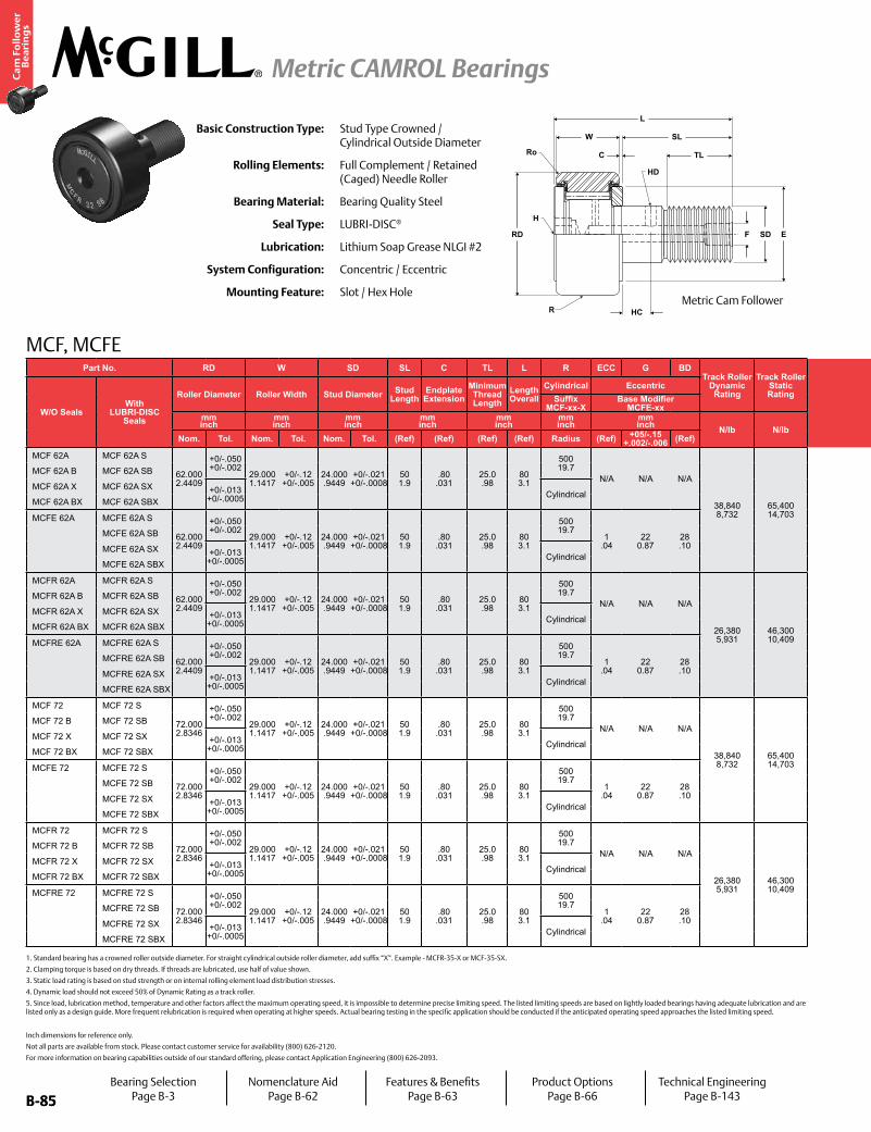
B-85
Ca
m F
oll
ow
er
Be
ari
ng
s
Metric CAMROL Bearings
B-85
MCF, MCFE
Inch dimensions for reference only.
Not all parts are available from stock. Please contact customer service for availability (800) 626-2120.
For more information on bearing capabilities outside of our standard offering, please contact Application Engineering (800) 626-2093.
Basic Construction Type: Stud Type Crowned / Cylindrical Outside Diameter
Rolling Elements: Full Complement / Retained (Caged) Needle Roller
Bearing Material: Bearing Quality Steel
Seal Type: LUBRI-DISC®
Lubrication: Lithium Soap Grease NLGI #2
System Configuration: Concentric / Eccentric
Mounting Feature: Slot / Hex Hole
1. Standard bearing has a crowned roller outside diameter. For straight cylindrical outside roller diameter, add suffix “X”. Example - MCFR-35-X or MCF-35-SX.
2. Clamping torque is based on dry threads. If threads are lubricated, use half of value shown.
3. Static load rating is based on stud strength or on internal rolling element load distribution stresses.
4. Dynamic load should not exceed 50% of Dynamic Rating as a track roller.
5. Since load, lubrication method, temperature and other factors affect the maximum operating speed, it is impossible to determine precise limiting speed. The listed limiting speeds are based on lightly loaded bearings having adequate lubrication and are listed only as a design guide. More frequent relubrication is required when operating at higher speeds. Actual bearing testing in the specific application should be conducted if the anticipated operating speed approaches the listed limiting speed.
Part No. RD W SD SL C TL L R ECC G BDTrack Roller
Dynamic Rating
Track Roller Static Rating
Part No. HC HD F H Ro E Housing Bore
DiameterThread Type
Clamping Torque
Limiting Speed
(Grease)
WT
W/O SealsWith
LUBRI-DISC Seals
Roller Diameter Roller Width Stud Diameter Stud Length
Endplate Extension
Minimum Thread Length
Length Overall
Cylindrical Eccentric
W/O SealsWith
LUBRI-DISC Seals
Hole Center
Radial Lub. Hole
DiameterLub. Hole
DiaHex Hole Outer
CornerMin.
Clamping Diameter
Bearing WeightSuffix
MCF-xx-XBase Modifier
MCFE-xxSuffix
MCF_xx Bmm inch
mm inch
mm inch
mm inch
mm inch
mm inch
mm inch N/lb N/lb
mm inch
mm inch
mm inch
mm inch Nm
in-lb RPM kglbNom. Tol. Nom. Tol. Nom. Tol. (Ref) (Ref) (Ref) (Ref) Radius (Ref) +05/-.15
+.002/-.006 (Ref) (Ref) (Ref) (Ref) (Ref) (Ref) (Ref) Nom. Tol.
MCF 62A MCF 62A S
62.000 2.4409
+0/-.050 +0/-.002
29.000 1.1417
+0/-.12 +0/-.005
24.000 .9449
+0/-.021 +0/-.0008
50 1.9
.80 .031
25.0 .98
80 3.1
500 19.7
N/A N/A N/A
38,840 8,732
65,400 14,703
MCF 62A MCF 62A S
12 .472
4 .157
8 .31 N/A
2.0 .08
63 2.5
24.000 .9449
+.021/-0 +.0008/- 0 M24x1.5 216
1,912 2,100 .81 1.79
MCF 62A B MCF 62A SB MCF 62A B MCF 62A SB - 14 .55
MCF 62A X MCF 62A SX +0/-.013 +0/-.0005 Cylindrical
MCF 62A X MCF 62A SX 8 .31 N/A
MCF 62A BX MCF 62A SBX MCF 62A BX MCF 62A SBX - 14 .55
MCFE 62A MCFE 62A S
62.000 2.4409
+0/-.050 +0/-.002
29.000 1.1417
+0/-.12 +0/-.005
24.000 .9449
+0/-.021 +0/-.0008
50 1.9
.80 .031
25.0 .98
80 3.1
500 19.7
1 .04
22 0.87
28 .10
MCFE 62A MCFE 62A S
N/A N/A
8 .31 N/A
2.0 .08
63 2.5
28.050 .1043
+0.025/-0 +0.0009/- 0 M24x1.5 216
1,912 2,100 .81 1.79
MCFE 62A SB MCFE 62A SB - 14 .55
MCFE 62A SX +0/-.013 +0/-.0005 Cylindrical
MCFE 62A SX 8 .31 N/A
MCFE 62A SBX MCFE 62A SBX - 14 .55
MCFR 62A MCFR 62A S
62.000 2.4409
+0/-.050 +0/-.002
29.000 1.1417
+0/-.12 +0/-.005
24.000 .9449
+0/-.021 +0/-.0008
50 1.9
.80 .031
25.0 .98
80 3.1
500 19.7
N/A N/A N/A
26,380 5,931
46,300 10,409
MCFR 62A MCFR 62A S
12 .472
4 .157
8 .31 N/A
2.0 .08
63 2.5
24.000 .9449
+.021/-0 +.0008/- 0 M24x1.5 216
1,912 3,100 .81 1.79
MCFR 62A B MCFR 62A SB MCFR 62A B MCFR 62A SB - 14 .55
MCFR 62A X MCFR 62A SX +0/-.013 +0/-.0005 Cylindrical
MCFR 62A X MCFR 62A SX 8 .31 N/A
MCFR 62A BX MCFR 62A SBX MCFR 62A BX MCFR 62A SBX - 14 .55
MCFRE 62A MCFRE 62A S
62.000 2.4409
+0/-.050 +0/-.002
29.000 1.1417
+0/-.12 +0/-.005
24.000 .9449
+0/-.021 +0/-.0008
50 1.9
.80 .031
25.0 .98
80 3.1
500 19.7
1 .04
22 0.87
28 .10
MCFRE 62A MCFRE 62A S
N/A N/A
8 .31 N/A
2.0 .08
63 2.5
28.050 .1043
+0.025/-0 +0.0009/- 0 M24x1.5 216
1,912 3,100 .81 1.79
MCFRE 62A SB MCFRE 62A SB - 14 .55
MCFRE 62A SX +0/-.013 +0/-.0005 Cylindrical
MCFRE 62A SX 8 .31 N/A
MCFRE 62A SBX MCFRE 62A SBX - 14 .55
MCF 72 MCF 72 S
72.000 2.8346
+0/-.050 +0/-.002
29.000 1.1417
+0/-.12 +0/-.005
24.000 .9449
+0/-.021 +0/-.0008
50 1.9
.80 .031
25.0 .98
80 3.1
500 19.7
N/A N/A N/A
38,840 8,732
65,400 14,703
MCF 72 MCF 72 S
12 .472
4 .157
8 .31 N/A
2.0 .08
63 2.5
24.000 .9449
+.021/-0 +.0008/- 0 M24x1.5 216
1,912 2,100 1.04 2.29
MCF 72 B MCF 72 SB MCF 72 B MCF 72 SB - 14 .55
MCF 72 X MCF 72 SX +0/-.013 +0/-.0005 Cylindrical
MCF 72 X MCF 72 SX 8 .31 N/A
MCF 72 BX MCF 72 SBX MCF 72 BX MCF 72 SBX - 14 .55
MCFE 72 MCFE 72 S
72.000 2.8346
+0/-.050 +0/-.002
29.000 1.1417
+0/-.12 +0/-.005
24.000 .9449
+0/-.021 +0/-.0008
50 1.9
.80 .031
25.0 .98
80 3.1
500 19.7
1 .04
22 0.87
28 .10
MCFE 72 MCFE 72 S
N/A N/A
8 .31 N/A
2.0 .08
63 2.5
28.050 .1043
+0.025/-0 +0.0009/- 0 M24x1.5 216
1,912 2,100 1.04 2.29
MCFE 72 SB MCFE 72 SB - 14 .55
MCFE 72 SX +0/-.013 +0/-.0005 Cylindrical
MCFE 72 SX 8 .31 N/A
MCFE 72 SBX MCFE 72 SBX - 14 .55
MCFR 72 MCFR 72 S
72.000 2.8346
+0/-.050 +0/-.002
29.000 1.1417
+0/-.12 +0/-.005
24.000 .9449
+0/-.021 +0/-.0008
50 1.9
.80 .031
25.0 .98
80 3.1
500 19.7
N/A N/A N/A
26,380 5,931
46,300 10,409
MCFR 72 MCFR 72 S
12 .472
4 .157
8 .31 N/A
2.0 .08
63 2.5
24.000 .9449
+.021/-0 +.0008/- 0 M24x1.5 216
1,912 3,100 1.04 2.29
MCFR 72 B MCFR 72 SB MCFR 72 B MCFR 72 SB - 14 .55
MCFR 72 X MCFR 72 SX +0/-.013 +0/-.0005 Cylindrical
MCFR 72 X MCFR 72 SX 8 .31 N/A
MCFR 72 BX MCFR 72 SBX MCFR 72 BX MCFR 72 SBX - 14 .55
MCFRE 72 MCFRE 72 S
72.000 2.8346
+0/-.050 +0/-.002
29.000 1.1417
+0/-.12 +0/-.005
24.000 .9449
+0/-.021 +0/-.0008
50 1.9
.80 .031
25.0 .98
80 3.1
500 19.7
1 .04
22 0.87
28 .10
MCFRE 72 MCFRE 72 S
N/A N/A
8 .31 N/A
2.0 .08
63 2.5
28.050 .1043
+0.025/-0 +0.0009/- 0 M24x1.5 216
1,912 3,100 1.04 2.29
MCFRE 72 SB MCFRE 72 SB - 14 .55
MCFRE 72 SX +0/-.013 +0/-.0005 Cylindrical
MCFRE 72 SX 8 .31 N/A
MCFRE 72 SBX MCFRE 72 SBX - 14 .55
W
C
SL
TL
F SD E
HC
RD
H
HD
Ro
L
RMetric Cam Follower
Bearing SelectionPage B-3
Nomenclature AidPage B-62
Features & BenefitsPage B-63
Product OptionsPage B-66
Technical EngineeringPage B-143
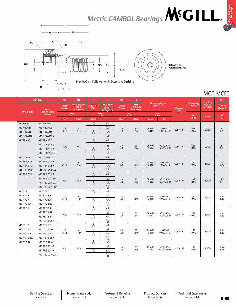
B-86
Ca
m F
oll
ow
er
Be
ari
ng
s
Metric CAMROL Bearings
B-86
MCF, MCFEPart No. RD W SD SL C TL L R ECC G BD
Track Roller Dynamic Rating
Track Roller Static Rating
Part No. HC HD F H Ro E Housing Bore
DiameterThread Type
Clamping Torque
Limiting Speed
(Grease)
WT
W/O SealsWith
LUBRI-DISC Seals
Roller Diameter Roller Width Stud Diameter Stud Length
Endplate Extension
Minimum Thread Length
Length Overall
Cylindrical Eccentric
W/O SealsWith
LUBRI-DISC Seals
Hole Center
Radial Lub. Hole
DiameterLub. Hole
DiaHex Hole Outer
CornerMin.
Clamping Diameter
Bearing WeightSuffix
MCF-xx-XBase Modifier
MCFE-xxSuffix
MCF_xx Bmm inch
mm inch
mm inch
mm inch
mm inch
mm inch
mm inch N/lb N/lb
mm inch
mm inch
mm inch
mm inch Nm
in-lb RPM kglbNom. Tol. Nom. Tol. Nom. Tol. (Ref) (Ref) (Ref) (Ref) Radius (Ref) +05/-.15
+.002/-.006 (Ref) (Ref) (Ref) (Ref) (Ref) (Ref) (Ref) Nom. Tol.
MCF 62A MCF 62A S
62.000 2.4409
+0/-.050 +0/-.002
29.000 1.1417
+0/-.12 +0/-.005
24.000 .9449
+0/-.021 +0/-.0008
50 1.9
.80 .031
25.0 .98
80 3.1
500 19.7
N/A N/A N/A
38,840 8,732
65,400 14,703
MCF 62A MCF 62A S
12 .472
4 .157
8 .31 N/A
2.0 .08
63 2.5
24.000 .9449
+.021/-0 +.0008/- 0 M24x1.5 216
1,912 2,100 .81 1.79
MCF 62A B MCF 62A SB MCF 62A B MCF 62A SB - 14 .55
MCF 62A X MCF 62A SX +0/-.013 +0/-.0005 Cylindrical
MCF 62A X MCF 62A SX 8 .31 N/A
MCF 62A BX MCF 62A SBX MCF 62A BX MCF 62A SBX - 14 .55
MCFE 62A MCFE 62A S
62.000 2.4409
+0/-.050 +0/-.002
29.000 1.1417
+0/-.12 +0/-.005
24.000 .9449
+0/-.021 +0/-.0008
50 1.9
.80 .031
25.0 .98
80 3.1
500 19.7
1 .04
22 0.87
28 .10
MCFE 62A MCFE 62A S
N/A N/A
8 .31 N/A
2.0 .08
63 2.5
28.050 .1043
+0.025/-0 +0.0009/- 0 M24x1.5 216
1,912 2,100 .81 1.79
MCFE 62A SB MCFE 62A SB - 14 .55
MCFE 62A SX +0/-.013 +0/-.0005 Cylindrical
MCFE 62A SX 8 .31 N/A
MCFE 62A SBX MCFE 62A SBX - 14 .55
MCFR 62A MCFR 62A S
62.000 2.4409
+0/-.050 +0/-.002
29.000 1.1417
+0/-.12 +0/-.005
24.000 .9449
+0/-.021 +0/-.0008
50 1.9
.80 .031
25.0 .98
80 3.1
500 19.7
N/A N/A N/A
26,380 5,931
46,300 10,409
MCFR 62A MCFR 62A S
12 .472
4 .157
8 .31 N/A
2.0 .08
63 2.5
24.000 .9449
+.021/-0 +.0008/- 0 M24x1.5 216
1,912 3,100 .81 1.79
MCFR 62A B MCFR 62A SB MCFR 62A B MCFR 62A SB - 14 .55
MCFR 62A X MCFR 62A SX +0/-.013 +0/-.0005 Cylindrical
MCFR 62A X MCFR 62A SX 8 .31 N/A
MCFR 62A BX MCFR 62A SBX MCFR 62A BX MCFR 62A SBX - 14 .55
MCFRE 62A MCFRE 62A S
62.000 2.4409
+0/-.050 +0/-.002
29.000 1.1417
+0/-.12 +0/-.005
24.000 .9449
+0/-.021 +0/-.0008
50 1.9
.80 .031
25.0 .98
80 3.1
500 19.7
1 .04
22 0.87
28 .10
MCFRE 62A MCFRE 62A S
N/A N/A
8 .31 N/A
2.0 .08
63 2.5
28.050 .1043
+0.025/-0 +0.0009/- 0 M24x1.5 216
1,912 3,100 .81 1.79
MCFRE 62A SB MCFRE 62A SB - 14 .55
MCFRE 62A SX +0/-.013 +0/-.0005 Cylindrical
MCFRE 62A SX 8 .31 N/A
MCFRE 62A SBX MCFRE 62A SBX - 14 .55
MCF 72 MCF 72 S
72.000 2.8346
+0/-.050 +0/-.002
29.000 1.1417
+0/-.12 +0/-.005
24.000 .9449
+0/-.021 +0/-.0008
50 1.9
.80 .031
25.0 .98
80 3.1
500 19.7
N/A N/A N/A
38,840 8,732
65,400 14,703
MCF 72 MCF 72 S
12 .472
4 .157
8 .31 N/A
2.0 .08
63 2.5
24.000 .9449
+.021/-0 +.0008/- 0 M24x1.5 216
1,912 2,100 1.04 2.29
MCF 72 B MCF 72 SB MCF 72 B MCF 72 SB - 14 .55
MCF 72 X MCF 72 SX +0/-.013 +0/-.0005 Cylindrical
MCF 72 X MCF 72 SX 8 .31 N/A
MCF 72 BX MCF 72 SBX MCF 72 BX MCF 72 SBX - 14 .55
MCFE 72 MCFE 72 S
72.000 2.8346
+0/-.050 +0/-.002
29.000 1.1417
+0/-.12 +0/-.005
24.000 .9449
+0/-.021 +0/-.0008
50 1.9
.80 .031
25.0 .98
80 3.1
500 19.7
1 .04
22 0.87
28 .10
MCFE 72 MCFE 72 S
N/A N/A
8 .31 N/A
2.0 .08
63 2.5
28.050 .1043
+0.025/-0 +0.0009/- 0 M24x1.5 216
1,912 2,100 1.04 2.29
MCFE 72 SB MCFE 72 SB - 14 .55
MCFE 72 SX +0/-.013 +0/-.0005 Cylindrical
MCFE 72 SX 8 .31 N/A
MCFE 72 SBX MCFE 72 SBX - 14 .55
MCFR 72 MCFR 72 S
72.000 2.8346
+0/-.050 +0/-.002
29.000 1.1417
+0/-.12 +0/-.005
24.000 .9449
+0/-.021 +0/-.0008
50 1.9
.80 .031
25.0 .98
80 3.1
500 19.7
N/A N/A N/A
26,380 5,931
46,300 10,409
MCFR 72 MCFR 72 S
12 .472
4 .157
8 .31 N/A
2.0 .08
63 2.5
24.000 .9449
+.021/-0 +.0008/- 0 M24x1.5 216
1,912 3,100 1.04 2.29
MCFR 72 B MCFR 72 SB MCFR 72 B MCFR 72 SB - 14 .55
MCFR 72 X MCFR 72 SX +0/-.013 +0/-.0005 Cylindrical
MCFR 72 X MCFR 72 SX 8 .31 N/A
MCFR 72 BX MCFR 72 SBX MCFR 72 BX MCFR 72 SBX - 14 .55
MCFRE 72 MCFRE 72 S
72.000 2.8346
+0/-.050 +0/-.002
29.000 1.1417
+0/-.12 +0/-.005
24.000 .9449
+0/-.021 +0/-.0008
50 1.9
.80 .031
25.0 .98
80 3.1
500 19.7
1 .04
22 0.87
28 .10
MCFRE 72 MCFRE 72 S
N/A N/A
8 .31 N/A
2.0 .08
63 2.5
28.050 .1043
+0.025/-0 +0.0009/- 0 M24x1.5 216
1,912 3,100 1.04 2.29
MCFRE 72 SB MCFRE 72 SB - 14 .55
MCFRE 72 SX +0/-.013 +0/-.0005 Cylindrical
MCFRE 72 SX 8 .31 N/A
MCFRE 72 SBX MCFRE 72 SBX - 14 .55
Metric Cam Follower with Eccentric Bushing
Bearing SelectionPage B-3
Nomenclature AidPage B-62
Features & BenefitsPage B-63
Product OptionsPage B-66
Technical EngineeringPage B-143
HC
HDRo
SD BEARING CENTERLINE
ECC
RD
C
SL
TL
L
E
GR
F BDF
W

B-87
Ca
m F
oll
ow
er
Be
ari
ng
s
Metric CAMROL Bearings
B-87
MCF, MCFE
Inch dimensions for reference only.
Not all parts are available from stock. Please contact customer service for availability (800) 626-2120.
For more information on bearing capabilities outside of our standard offering, please contact Application Engineering (800) 626-2093.
Basic Construction Type: Stud Type Crowned / Cylindrical Outside Diameter
Rolling Elements: Full Complement / Retained (Caged) Needle Roller
Bearing Material: Bearing Quality Steel
Seal Type: LUBRI-DISC®
Lubrication: Lithium Soap Grease NLGI #2
System Configuration: Concentric / Eccentric
Mounting Feature: Slot / Hex Hole
1. Standard bearing has a crowned roller outside diameter. For straight cylindrical outside roller diameter, add suffix “X”. Example - MCFR-35-X or MCF-35-SX.
2. Clamping torque is based on dry threads. If threads are lubricated, use half of value shown.
3. Static load rating is based on stud strength or on internal rolling element load distribution stresses.
4. Dynamic load should not exceed 50% of Dynamic Rating as a track roller.
5. Since load, lubrication method, temperature and other factors affect the maximum operating speed, it is impossible to determine precise limiting speed. The listed limiting speeds are based on lightly loaded bearings having adequate lubrication and are listed only as a design guide. More frequent relubrication is required when operating at higher speeds. Actual bearing testing in the specific application should be conducted if the anticipated operating speed approaches the listed limiting speed.
Part No. RD W SD SL C TL L R ECC G BDTrack Roller
Dynamic Rating
Track Roller Static Rating
Part No. HC HD F H Ro E Housing Bore
DiameterThread Type
Clamping Torque
Limiting Speed
(Grease)
WT
W/O SealsWith
LUBRI-DISC Seals
Roller Diameter Roller Width Stud Diameter Stud Length
Endplate Extension
Minimum Thread Length
Length Overall
Cylindrical Eccentric
W/O SealsWith
LUBRI-DISC Seals
Hole Center
Radial Lub. Hole
DiameterLub. Hole
DiaHex Hole Outer
CornerMin.
Clamping Diameter
Bearing WeightSuffix
MCF-xx-XBase Modifier
MCFE-xxSuffix
MCF_xx Bmm inch
mm inch
mm inch
mm inch
mm inch
mm inch
mm inch N/lb N/lb
mm inch
mm inch
mm inch
mm inch Nm
in-lb RPM kglbNom. Tol. Nom. Tol. Nom. Tol. (Ref) (Ref) (Ref) (Ref) Radius (Ref) +05/-.15
+.002/-.006 (Ref) (Ref) (Ref) (Ref) (Ref) (Ref) (Ref) Nom. Tol.
MCF 72A MCF 72A S
72.000 2.8346
+0/-.050 +0/-.002
29.000 1.1417
+0/-.12 +0/-.005
24.000 .9449
+0/-.021 +0/-.0008
50 1.9
.80 .031
25.0 .98
80 3.1
500 19.7
N/A N/A N/A
38,840 8,732
65,400 14,703
MCF 72A MCF 72A S
11 .433
4 .157
8 .31 N/A
2.0 .08
63 2.5
24.000 .9449
+.021/-0 +.0008/- 0 M24x1.5 216
1,912 2,100 1.04 2.29
MCF 72A B MCF 72A SB MCF 72A B MCF 72A SB - 14 .55
MCF 72A X MCF 72A SX +0/-.013 +0/-.0005 Cylindrical
MCF 72A X MCF 72A SX 8 .31 N/A
MCF 72A BX MCF 72A SBX MCF 72A BX MCF 72A SBX - 14 .55
MCFE 72A MCFE 72A S
72.000 2.8346
+0/-.050 +0/-.002
29.000 1.1417
+0/-.12 +0/-.005
24.000 .9449
+0/-.021 +0/-.0008
50 1.9
.80 .031
25.0 .98
80 3.1
500 19.7
1 .04
22 0.87
28 .10
MCFE 72A MCFE 72A S
N/A N/A
8 .31 N/A
2.0 .08
63 2.5
28.050 .1043
+0.025/-0 +0.0009/- 0 M24x1.5 216
1,912 2,100 1.04 2.29
MCFE 72A SB MCFE 72A SB - 14 .55
MCFE 72A SX +0/-.013 +0/-.0005 Cylindrical
MCFE 72A SX 8 .31 N/A
MCFE 72A SBX MCFE 72A SBX - 14 .55
MCFR 72A MCFR 72A S
72.000 2.8346
+0/-.050 +0/-.002
29.000 1.1417
+0/-.12 +0/-.005
24.000 .9449
+0/-.021 +0/-.0008
50 1.9
.80 .031
25.0 .98
80 3.1
500 19.7
N/A N/A N/A
26,380 5,931
46,300 10,409
MCFR 72A MCFR 72A S
11 .433
4 .157
8 .31 N/A
2.0 .08
63 2.5
24.000 .9449
+.021/-0 +.0008/- 0 M24x1.5 216
1,912 3,100 1.04 2.29
MCFR 72A B MCFR 72A SB MCFR 72A B MCFR 72A SB - 14 .55
MCFR 72A X MCFR 72A SX +0/-.013 +0/-.0005 Cylindrical
MCFR 72A X MCFR 72A SX 8 .31 N/A
MCFR 72A BX MCFR 72A SBX MCFR 72A BX MCFR 72A SBX - 14 .55
MCFRE 72A MCFRE 72A S
72.000 2.8346
+0/-.050 +0/-.002
29.000 1.1417
+0/-.12 +0/-.005
24.000 .9449
+0/-.021 +0/-.0008
50 1.9
.80 .031
25.0 .98
80 3.1
500 19.7
1 .04
22 0.87
28 .10
MCFRE 72A MCFRE 72A S
N/A N/A
8 .31 N/A
2.0 .08
63 2.5
28.050 .1043
+0.025/-0 +0.0009/- 0 M24x1.5 216
1,912 3,100 1.04 2.29
MCFRE 72A SB MCFRE 72A SB - 14 .55
MCFRE 72A SX +0/-.013 +0/-.0005 Cylindrical
MCFRE 72A SX 8 .31 N/A
MCFRE 72A SBX MCFRE 72A SBX - 14 .55
MCF 80 MCF 80 S
80.000 3.1496
+0/-.050 +0/-.002
35.000 1.3780
+0/-.12 +0/-.005
30.000 1.1811
+0/-.021 +0/-.0008
63 2.5
1.00 .039
32.0 1.26
100 3.9
500 19.7
N/A N/A N/A
64,140 14,420
102,300 22,999
MCF 80 MCF 80 S
15 .591
4 .157
8 .31 N/A
2.0 .08
63 2.5
30.000 .1811
+.021/-0 +.0008/- 0 M30x1.5 441
3,903 1,500 1.64 3.62
MCF 80 B MCF 80 SB MCF 80 B MCF 80 SB - 14 .55
MCF 80 X MCF 80 SX +0/-.015 +0/-.0006 Cylindrical
MCF 80 X MCF 80 SX 8 .31 N/A
MCF 80 BX MCF 80 SBX MCF 80 BX MCF 80 SBX - 14 .55
MCFE 80 MCFE 80 S
80.000 3.1496
+0/-.050 +0/-.002
35.000 1.3780
+0/-.12 +0/-.005
30.000 1.1811
+0/-.021 +0/-.0008
63 2.5
1.00 .039
32.0 1.26
100 3.9
500 19.7
1.5 .06
29 1.14
35 .38
MCFE 80 MCFE 80 S
N/A N/A
8 .31 N/A
2.0 .08
63 2.5
35.050 .3799
+0.025/-0 +0.0009/- 0 M30x1.5 441
3,903 2,200 1.64 3.62
MCFE 80 SB MCFE 80 SB - 14 .55
MCFE 80 SX +0/-.015 +0/-.0006 Cylindrical
MCFE 80 SX 8 .31 N/A
MCFE 80 SBX MCFE 80 SBX - 14 .55
MCFR 80A MCFR 80A S
80.000 3.1496
+0/-.050 +0/-.002
35.000 1.3780
+0/-.12 +0/-.005
30.000 1.1811
+0/-.021 +0/-.0008
63 2.5
1.00 .039
32.0 1.26
100 3.9
500 19.7
N/A N/A N/A
46,680 10,495
87,600 19,694
MCFR 80A MCFR 80A S
15 .591
4 .157
8 .31 N/A
2.0 .08
63 2.5
30.000 .1811
+.021/-0 +.0008/- 0 M30x1.5 441
3,903 2,200 1.64 3.62
MCFR 80A B MCFR 80A SB MCFR 80A B MCFR 80A SB - 14 .55
MCFR 80A X MCFR 80A SX +0/-.015 +0/-.0006 Cylindrical
MCFR 80A X MCFR 80A SX 8 .31 N/A
MCFR 80A BX MCFR 80A SBX MCFR 80A BX MCFR 80A SBX - 14 .55
MCFRE 80A MCFRE 80A S
80.000 3.1496
+0/-.050 +0/-.002
35.000 1.3780
+0/-.12 +0/-.005
30.000 1.1811
+0/-.021 +0/-.0008
63 2.5
1.00 .039
32.0 1.26
100 3.9
500 19.7
1.5 .06
29 1.14
35 .38
MCFRE 80A MCFRE 80A S
N/A N/A
8 .31 N/A
2.0 .08
63 2.5
35.050 .3799
+0.025/-0 +0.0009/- 0 M30x1.5 441
3,903 2,200 1.64 3.62
MCFRE 80A SB MCFRE 80A SB - 14 .55
MCFRE 80A SX +0/-.015 +0/-.0006 Cylindrical
MCFRE 80A SX 8 .31 N/A
MCFRE 80A SBX MCFRE 80A SBX - 14 .55
W
C
SL
TL
F SD E
HC
RD
H
HD
Ro
L
RMetric Cam Follower
Bearing SelectionPage B-3
Nomenclature AidPage B-62
Features & BenefitsPage B-63
Product OptionsPage B-66
Technical EngineeringPage B-143

B-88
Ca
m F
oll
ow
er
Be
ari
ng
s
Metric CAMROL Bearings
B-88
MCF, MCFEPart No. RD W SD SL C TL L R ECC G BD
Track Roller Dynamic Rating
Track Roller Static Rating
Part No. HC HD F H Ro E Housing Bore
DiameterThread Type
Clamping Torque
Limiting Speed
(Grease)
WT
W/O SealsWith
LUBRI-DISC Seals
Roller Diameter Roller Width Stud Diameter Stud Length
Endplate Extension
Minimum Thread Length
Length Overall
Cylindrical Eccentric
W/O SealsWith
LUBRI-DISC Seals
Hole Center
Radial Lub. Hole
DiameterLub. Hole
DiaHex Hole Outer
CornerMin.
Clamping Diameter
Bearing WeightSuffix
MCF-xx-XBase Modifier
MCFE-xxSuffix
MCF_xx Bmm inch
mm inch
mm inch
mm inch
mm inch
mm inch
mm inch N/lb N/lb
mm inch
mm inch
mm inch
mm inch Nm
in-lb RPM kglbNom. Tol. Nom. Tol. Nom. Tol. (Ref) (Ref) (Ref) (Ref) Radius (Ref) +05/-.15
+.002/-.006 (Ref) (Ref) (Ref) (Ref) (Ref) (Ref) (Ref) Nom. Tol.
MCF 72A MCF 72A S
72.000 2.8346
+0/-.050 +0/-.002
29.000 1.1417
+0/-.12 +0/-.005
24.000 .9449
+0/-.021 +0/-.0008
50 1.9
.80 .031
25.0 .98
80 3.1
500 19.7
N/A N/A N/A
38,840 8,732
65,400 14,703
MCF 72A MCF 72A S
11 .433
4 .157
8 .31 N/A
2.0 .08
63 2.5
24.000 .9449
+.021/-0 +.0008/- 0 M24x1.5 216
1,912 2,100 1.04 2.29
MCF 72A B MCF 72A SB MCF 72A B MCF 72A SB - 14 .55
MCF 72A X MCF 72A SX +0/-.013 +0/-.0005 Cylindrical
MCF 72A X MCF 72A SX 8 .31 N/A
MCF 72A BX MCF 72A SBX MCF 72A BX MCF 72A SBX - 14 .55
MCFE 72A MCFE 72A S
72.000 2.8346
+0/-.050 +0/-.002
29.000 1.1417
+0/-.12 +0/-.005
24.000 .9449
+0/-.021 +0/-.0008
50 1.9
.80 .031
25.0 .98
80 3.1
500 19.7
1 .04
22 0.87
28 .10
MCFE 72A MCFE 72A S
N/A N/A
8 .31 N/A
2.0 .08
63 2.5
28.050 .1043
+0.025/-0 +0.0009/- 0 M24x1.5 216
1,912 2,100 1.04 2.29
MCFE 72A SB MCFE 72A SB - 14 .55
MCFE 72A SX +0/-.013 +0/-.0005 Cylindrical
MCFE 72A SX 8 .31 N/A
MCFE 72A SBX MCFE 72A SBX - 14 .55
MCFR 72A MCFR 72A S
72.000 2.8346
+0/-.050 +0/-.002
29.000 1.1417
+0/-.12 +0/-.005
24.000 .9449
+0/-.021 +0/-.0008
50 1.9
.80 .031
25.0 .98
80 3.1
500 19.7
N/A N/A N/A
26,380 5,931
46,300 10,409
MCFR 72A MCFR 72A S
11 .433
4 .157
8 .31 N/A
2.0 .08
63 2.5
24.000 .9449
+.021/-0 +.0008/- 0 M24x1.5 216
1,912 3,100 1.04 2.29
MCFR 72A B MCFR 72A SB MCFR 72A B MCFR 72A SB - 14 .55
MCFR 72A X MCFR 72A SX +0/-.013 +0/-.0005 Cylindrical
MCFR 72A X MCFR 72A SX 8 .31 N/A
MCFR 72A BX MCFR 72A SBX MCFR 72A BX MCFR 72A SBX - 14 .55
MCFRE 72A MCFRE 72A S
72.000 2.8346
+0/-.050 +0/-.002
29.000 1.1417
+0/-.12 +0/-.005
24.000 .9449
+0/-.021 +0/-.0008
50 1.9
.80 .031
25.0 .98
80 3.1
500 19.7
1 .04
22 0.87
28 .10
MCFRE 72A MCFRE 72A S
N/A N/A
8 .31 N/A
2.0 .08
63 2.5
28.050 .1043
+0.025/-0 +0.0009/- 0 M24x1.5 216
1,912 3,100 1.04 2.29
MCFRE 72A SB MCFRE 72A SB - 14 .55
MCFRE 72A SX +0/-.013 +0/-.0005 Cylindrical
MCFRE 72A SX 8 .31 N/A
MCFRE 72A SBX MCFRE 72A SBX - 14 .55
MCF 80 MCF 80 S
80.000 3.1496
+0/-.050 +0/-.002
35.000 1.3780
+0/-.12 +0/-.005
30.000 1.1811
+0/-.021 +0/-.0008
63 2.5
1.00 .039
32.0 1.26
100 3.9
500 19.7
N/A N/A N/A
64,140 14,420
102,300 22,999
MCF 80 MCF 80 S
15 .591
4 .157
8 .31 N/A
2.0 .08
63 2.5
30.000 .1811
+.021/-0 +.0008/- 0 M30x1.5 441
3,903 1,500 1.64 3.62
MCF 80 B MCF 80 SB MCF 80 B MCF 80 SB - 14 .55
MCF 80 X MCF 80 SX +0/-.015 +0/-.0006 Cylindrical
MCF 80 X MCF 80 SX 8 .31 N/A
MCF 80 BX MCF 80 SBX MCF 80 BX MCF 80 SBX - 14 .55
MCFE 80 MCFE 80 S
80.000 3.1496
+0/-.050 +0/-.002
35.000 1.3780
+0/-.12 +0/-.005
30.000 1.1811
+0/-.021 +0/-.0008
63 2.5
1.00 .039
32.0 1.26
100 3.9
500 19.7
1.5 .06
29 1.14
35 .38
MCFE 80 MCFE 80 S
N/A N/A
8 .31 N/A
2.0 .08
63 2.5
35.050 .3799
+0.025/-0 +0.0009/- 0 M30x1.5 441
3,903 2,200 1.64 3.62
MCFE 80 SB MCFE 80 SB - 14 .55
MCFE 80 SX +0/-.015 +0/-.0006 Cylindrical
MCFE 80 SX 8 .31 N/A
MCFE 80 SBX MCFE 80 SBX - 14 .55
MCFR 80A MCFR 80A S
80.000 3.1496
+0/-.050 +0/-.002
35.000 1.3780
+0/-.12 +0/-.005
30.000 1.1811
+0/-.021 +0/-.0008
63 2.5
1.00 .039
32.0 1.26
100 3.9
500 19.7
N/A N/A N/A
46,680 10,495
87,600 19,694
MCFR 80A MCFR 80A S
15 .591
4 .157
8 .31 N/A
2.0 .08
63 2.5
30.000 .1811
+.021/-0 +.0008/- 0 M30x1.5 441
3,903 2,200 1.64 3.62
MCFR 80A B MCFR 80A SB MCFR 80A B MCFR 80A SB - 14 .55
MCFR 80A X MCFR 80A SX +0/-.015 +0/-.0006 Cylindrical
MCFR 80A X MCFR 80A SX 8 .31 N/A
MCFR 80A BX MCFR 80A SBX MCFR 80A BX MCFR 80A SBX - 14 .55
MCFRE 80A MCFRE 80A S
80.000 3.1496
+0/-.050 +0/-.002
35.000 1.3780
+0/-.12 +0/-.005
30.000 1.1811
+0/-.021 +0/-.0008
63 2.5
1.00 .039
32.0 1.26
100 3.9
500 19.7
1.5 .06
29 1.14
35 .38
MCFRE 80A MCFRE 80A S
N/A N/A
8 .31 N/A
2.0 .08
63 2.5
35.050 .3799
+0.025/-0 +0.0009/- 0 M30x1.5 441
3,903 2,200 1.64 3.62
MCFRE 80A SB MCFRE 80A SB - 14 .55
MCFRE 80A SX +0/-.015 +0/-.0006 Cylindrical
MCFRE 80A SX 8 .31 N/A
MCFRE 80A SBX MCFRE 80A SBX - 14 .55
Metric Cam Follower with Eccentric Bushing
Bearing SelectionPage B-3
Nomenclature AidPage B-62
Features & BenefitsPage B-63
Product OptionsPage B-66
Technical EngineeringPage B-143
HC
HDRo
SD BEARING CENTERLINE
ECC
RD
C
SL
TL
L
E
GR
F BDF
W
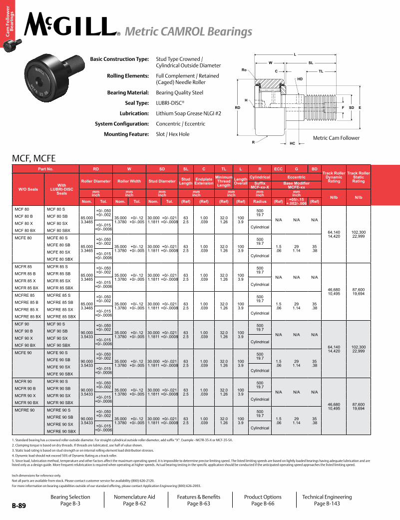
B-89
Ca
m F
oll
ow
er
Be
ari
ng
s
Metric CAMROL Bearings
B-89
MCF, MCFE
Inch dimensions for reference only.
Not all parts are available from stock. Please contact customer service for availability (800) 626-2120.
For more information on bearing capabilities outside of our standard offering, please contact Application Engineering (800) 626-2093.
Basic Construction Type: Stud Type Crowned / Cylindrical Outside Diameter
Rolling Elements: Full Complement / Retained (Caged) Needle Roller
Bearing Material: Bearing Quality Steel
Seal Type: LUBRI-DISC®
Lubrication: Lithium Soap Grease NLGI #2
System Configuration: Concentric / Eccentric
Mounting Feature: Slot / Hex Hole
1. Standard bearing has a crowned roller outside diameter. For straight cylindrical outside roller diameter, add suffix “X”. Example - MCFR-35-X or MCF-35-SX.
2. Clamping torque is based on dry threads. If threads are lubricated, use half of value shown.
3. Static load rating is based on stud strength or on internal rolling element load distribution stresses.
4. Dynamic load should not exceed 50% of Dynamic Rating as a track roller.
5. Since load, lubrication method, temperature and other factors affect the maximum operating speed, it is impossible to determine precise limiting speed. The listed limiting speeds are based on lightly loaded bearings having adequate lubrication and are listed only as a design guide. More frequent relubrication is required when operating at higher speeds. Actual bearing testing in the specific application should be conducted if the anticipated operating speed approaches the listed limiting speed.
Part No. RD W SD SL C TL L R ECC G BDTrack Roller
Dynamic Rating
Track Roller Static Rating
Part No. HC HD F H Ro E Housing Bore
DiameterThread Type
Clamping Torque
Limiting Speed
(Grease)
WT
W/O SealsWith
LUBRI-DISC Seals
Roller Diameter Roller Width Stud Diameter Stud Length
Endplate Extension
Minimum Thread Length
Length Overall
Cylindrical Eccentric
W/O SealsWith
LUBRI-DISC Seals
Hole Center
Radial Lub. Hole
DiameterLub. Hole
DiaHex Hole Outer
CornerMin.
Clamping Diameter
Bearing WeightSuffix
MCF-xx-XBase Modifier
MCFE-xxSuffix
MCF_xx Bmm inch
mm inch
mm inch
mm inch
mm inch
mm inch
mm inch N/lb N/lb
mm inch
mm inch
mm inch
mm inch Nm
in-lb RPM kglbNom. Tol. Nom. Tol. Nom. Tol. (Ref) (Ref) (Ref) (Ref) Radius (Ref) +05/-.15
+.002/-.006 (Ref) (Ref) (Ref) (Ref) (Ref) (Ref) (Ref) Nom. Tol.
MCF 80 MCF 80 S
85.000 3.3465
+0/-.050 +0/-.002
35.000 1.3780
+0/-.12 +0/-.005
30.000 1.1811
+0/-.021 +0/-.0008
63 2.5
1.00 .039
32.0 1.26
100 3.9
500 19.7
N/A N/A N/A
64,140 14,420
102,300 22,999
MCF 80 MCF 80 S
15 .591
4 .157
8 .31 N/A
2.0 .08
63 2.5
30.000 .1811
+.021/-0 +.0008/- 0 M30x1.5 441
3,903 1,500 1.64 3.62
MCF 80 B MCF 80 SB MCF 80 B MCF 80 SB - 14 .55
MCF 80 X MCF 80 SX +0/-.015 +0/-.0006 Cylindrical
MCF 80 X MCF 80 SX 8 .31 N/A
MCF 80 BX MCF 80 SBX MCF 80 BX MCF 80 SBX - 14 .55
MCFE 80 MCFE 80 S
85.000 3.3465
+0/-.050 +0/-.002
35.000 1.3780
+0/-.12 +0/-.005
30.000 1.1811
+0/-.021 +0/-.0008
63 2.5
1.00 .039
32.0 1.26
100 3.9
500 19.7
1.5 .06
29 1.14
35 .38
MCFE 80 MCFE 80 S
15 .591
4 .157
8 .31 N/A
2.0 .08
63 2.5
35.050 .3799
+0.025/-0 +0.0009/- 0 M30x1.5 441
3,903 1,500 1.64 3.62
MCFE 80 SB MCFE 80 SB - 14 .55
MCFE 80 SX +0/-.015 +0/-.0006 Cylindrical
MCFE 80 SX 8 .31 N/A
MCFE 80 SBX MCFE 80 SBX - 14 .55
MCFR 85 MCFR 85 S
85.000 3.3465
+0/-.050 +0/-.002
35.000 1.3780
+0/-.12 +0/-.005
30.000 1.1811
+0/-.021 +0/-.0008
63 2.5
1.00 .039
32.0 1.26
100 3.9
500 19.7
N/A N/A N/A
46,680 10,495
87,600 19,694
MCFR 85 MCFR 85 S
15 .591
4 .157
8 .31 N/A
2.0 .08
63 2.5
30.000 .1811
+.021/-0 +.0008/- 0 M30x1.5 441
3,903 2,200 1.81 3.99
MCFR 85 B MCFR 85 SB MCFR 85 B MCFR 85 SB - 14 .55
MCFR 85 X MCFR 85 SX +0/-.015 +0/-.0006 Cylindrical
MCFR 85 X MCFR 85 SX 8 .31 N/A
MCFR 85 BX MCFR 85 SBX MCFR 85 BX MCFR 85 SBX - 14 .55
MCFRE 85 MCFRE 85 S
85.000 3.3465
+0/-.050 +0/-.002
35.000 1.3780
+0/-.12 +0/-.005
30.000 1.1811
+0/-.021 +0/-.0008
63 2.5
1.00 .039
32.0 1.26
100 3.9
500 19.7
1.5 .06
29 1.14
35 .38
MCFRE 85 MCFRE 85 S
N/A N/A
8 .31 N/A
2.0 .08
63 2.5
35.050 .3799
+0.025/-0 +0.0009/- 0 M30x1.5 441
3,903 2,200 1.81 3.99
MCFRE 85 B MCFRE 85 SB MCFRE 85 B MCFRE 85 SB - 14 .55
MCFRE 85 X MCFRE 85 SX +0/-.015 +0/-.0006 Cylindrical
MCFRE 85 X MCFRE 85 SX 8 .31 N/A
MCFRE 85 BX MCFRE 85 SBX MCFRE 85 BX MCFRE 85 SBX - 14 .55
MCF 90 MCF 90 S
90.000 3.5433
+0/-.050 +0/-.002
35.000 1.3780
+0/-.12 +0/-.005
30.000 1.1811
+0/-.021 +0/-.0008
63 2.5
1.00 .039
32.0 1.26
100 3.9
500 19.7
N/A N/A N/A
64,140 14,420
102,300 22,999
MCF 90 MCF 90 S
15 .591
4 .157
8 .31 N/A
2.0 .08
68 2.7
30.000 .1811
+.021/-0 +.0008/- 0 M30x1.5 441
3,903 1,500 1.99 4.39
MCF 90 B MCF 90 SB MCF 90 B MCF 90 SB - 14 .55
MCF 90 X MCF 90 SX +0/-.015 +0/-.0006 Cylindrical
MCF 90 X MCF 90 SX 8 .31 N/A
MCF 90 BX MCF 90 SBX MCF 90 BX MCF 90 SBX - 14 .55
MCFE 90 MCFE 90 S
90.000 3.5433
+0/-.050 +0/-.002
35.000 1.3780
+0/-.12 +0/-.005
30.000 1.1811
+0/-.021 +0/-.0008
63 2.5
1.00 .039
32.0 1.26
100 3.9
500 19.7
1.5 .06
29 1.14
35 .38
MCFE 90 MCFE 90 S
15 .591
4 .157
8 .31 N/A
2.0 .08
68 2.7
35.050 .3799
+0.025/-0 +0.0009/- 0 M30x1.5 441
3,903 1,500 1.99 4.39
MCFE 90 SB MCFE 90 SB - 14 .55
MCFE 90 SX +0/-.015 +0/-.0006 Cylindrical
MCFE 90 SX 8 .31 N/A
MCFE 90 SBX MCFE 90 SBX - 14 .55
MCFR 90 MCFR 90 S
90.000 3.5433
+0/-.050 +0/-.002
35.000 1.3780
+0/-.12 +0/-.005
30.000 1.1811
+0/-.021 +0/-.0008
63 2.5
1.00 .039
32.0 1.26
100 3.9
500 19.7
N/A N/A N/A
46,680 10,495
87,600 19,694
MCFR 90 MCFR 90 S
15 .591
4 .157
8 .31 N/A
2.0 .08
68 2.7
30.000 .1811
+.021/-0 +.0008/- 0 M30x1.5 441
3,903 2,200 1.99 4.39
MCFR 90 B MCFR 90 SB MCFR 90 B MCFR 90 SB - 14 .55
MCFR 90 X MCFR 90 SX +0/-.015 +0/-.0006 Cylindrical
MCFR 90 X MCFR 90 SX 8 .31 N/A
MCFR 90 BX MCFR 90 SBX MCFR 90 BX MCFR 90 SBX - 14 .55
MCFRE 90 MCFRE 90 S
90.000 3.5433
+0/-.050 +0/-.002
35.000 1.3780
+0/-.12 +0/-.005
30.000 1.1811
+0/-.021 +0/-.0008
63 2.5
1.00 .039
32.0 1.26
100 3.9
500 19.7
1.5 .06
29 1.14
35 .38
MCFRE 90 MCFRE 90 S
N/A N/A
8 .31 N/A
2.0 .08
68 2.7
35.050 .3799
+0.025/-0 +0.0009/- 0 M30x1.5 441
3,903 2,200 1.99 4.39
MCFRE 90 SB MCFRE 90 SB - 14 .55
MCFRE 90 SX +0/-.015 +0/-.0006 Cylindrical
MCFRE 90 SX 8 .31 N/A
MCFRE 90 SBX MCFRE 90 SBX - 14 .55
W
C
SL
TL
F SD E
HC
RD
H
HD
Ro
L
RMetric Cam Follower
Bearing SelectionPage B-3
Nomenclature AidPage B-62
Features & BenefitsPage B-63
Product OptionsPage B-66
Technical EngineeringPage B-143
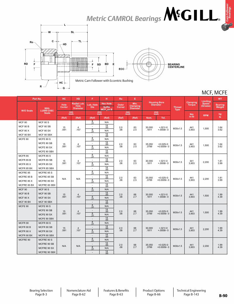
B-90
Ca
m F
oll
ow
er
Be
ari
ng
s
Metric CAMROL Bearings
B-90
MCF, MCFEPart No. RD W SD SL C TL L R ECC G BD
Track Roller Dynamic Rating
Track Roller Static Rating
Part No. HC HD F H Ro E Housing Bore
DiameterThread Type
Clamping Torque
Limiting Speed
(Grease)
WT
W/O SealsWith
LUBRI-DISC Seals
Roller Diameter Roller Width Stud Diameter Stud Length
Endplate Extension
Minimum Thread Length
Length Overall
Cylindrical Eccentric
W/O SealsWith
LUBRI-DISC Seals
Hole Center
Radial Lub. Hole
DiameterLub. Hole
DiaHex Hole Outer
CornerMin.
Clamping Diameter
Bearing WeightSuffix
MCF-xx-XBase Modifier
MCFE-xxSuffix
MCF_xx Bmm inch
mm inch
mm inch
mm inch
mm inch
mm inch
mm inch N/lb N/lb
mm inch
mm inch
mm inch
mm inch Nm
in-lb RPM kglbNom. Tol. Nom. Tol. Nom. Tol. (Ref) (Ref) (Ref) (Ref) Radius (Ref) +05/-.15
+.002/-.006 (Ref) (Ref) (Ref) (Ref) (Ref) (Ref) (Ref) Nom. Tol.
MCF 80 MCF 80 S
85.000 3.3465
+0/-.050 +0/-.002
35.000 1.3780
+0/-.12 +0/-.005
30.000 1.1811
+0/-.021 +0/-.0008
63 2.5
1.00 .039
32.0 1.26
100 3.9
500 19.7
N/A N/A N/A
64,140 14,420
102,300 22,999
MCF 80 MCF 80 S
15 .591
4 .157
8 .31 N/A
2.0 .08
63 2.5
30.000 .1811
+.021/-0 +.0008/- 0 M30x1.5 441
3,903 1,500 1.64 3.62
MCF 80 B MCF 80 SB MCF 80 B MCF 80 SB - 14 .55
MCF 80 X MCF 80 SX +0/-.015 +0/-.0006 Cylindrical
MCF 80 X MCF 80 SX 8 .31 N/A
MCF 80 BX MCF 80 SBX MCF 80 BX MCF 80 SBX - 14 .55
MCFE 80 MCFE 80 S
85.000 3.3465
+0/-.050 +0/-.002
35.000 1.3780
+0/-.12 +0/-.005
30.000 1.1811
+0/-.021 +0/-.0008
63 2.5
1.00 .039
32.0 1.26
100 3.9
500 19.7
1.5 .06
29 1.14
35 .38
MCFE 80 MCFE 80 S
15 .591
4 .157
8 .31 N/A
2.0 .08
63 2.5
35.050 .3799
+0.025/-0 +0.0009/- 0 M30x1.5 441
3,903 1,500 1.64 3.62
MCFE 80 SB MCFE 80 SB - 14 .55
MCFE 80 SX +0/-.015 +0/-.0006 Cylindrical
MCFE 80 SX 8 .31 N/A
MCFE 80 SBX MCFE 80 SBX - 14 .55
MCFR 85 MCFR 85 S
85.000 3.3465
+0/-.050 +0/-.002
35.000 1.3780
+0/-.12 +0/-.005
30.000 1.1811
+0/-.021 +0/-.0008
63 2.5
1.00 .039
32.0 1.26
100 3.9
500 19.7
N/A N/A N/A
46,680 10,495
87,600 19,694
MCFR 85 MCFR 85 S
15 .591
4 .157
8 .31 N/A
2.0 .08
63 2.5
30.000 .1811
+.021/-0 +.0008/- 0 M30x1.5 441
3,903 2,200 1.81 3.99
MCFR 85 B MCFR 85 SB MCFR 85 B MCFR 85 SB - 14 .55
MCFR 85 X MCFR 85 SX +0/-.015 +0/-.0006 Cylindrical
MCFR 85 X MCFR 85 SX 8 .31 N/A
MCFR 85 BX MCFR 85 SBX MCFR 85 BX MCFR 85 SBX - 14 .55
MCFRE 85 MCFRE 85 S
85.000 3.3465
+0/-.050 +0/-.002
35.000 1.3780
+0/-.12 +0/-.005
30.000 1.1811
+0/-.021 +0/-.0008
63 2.5
1.00 .039
32.0 1.26
100 3.9
500 19.7
1.5 .06
29 1.14
35 .38
MCFRE 85 MCFRE 85 S
N/A N/A
8 .31 N/A
2.0 .08
63 2.5
35.050 .3799
+0.025/-0 +0.0009/- 0 M30x1.5 441
3,903 2,200 1.81 3.99
MCFRE 85 B MCFRE 85 SB MCFRE 85 B MCFRE 85 SB - 14 .55
MCFRE 85 X MCFRE 85 SX +0/-.015 +0/-.0006 Cylindrical
MCFRE 85 X MCFRE 85 SX 8 .31 N/A
MCFRE 85 BX MCFRE 85 SBX MCFRE 85 BX MCFRE 85 SBX - 14 .55
MCF 90 MCF 90 S
90.000 3.5433
+0/-.050 +0/-.002
35.000 1.3780
+0/-.12 +0/-.005
30.000 1.1811
+0/-.021 +0/-.0008
63 2.5
1.00 .039
32.0 1.26
100 3.9
500 19.7
N/A N/A N/A
64,140 14,420
102,300 22,999
MCF 90 MCF 90 S
15 .591
4 .157
8 .31 N/A
2.0 .08
68 2.7
30.000 .1811
+.021/-0 +.0008/- 0 M30x1.5 441
3,903 1,500 1.99 4.39
MCF 90 B MCF 90 SB MCF 90 B MCF 90 SB - 14 .55
MCF 90 X MCF 90 SX +0/-.015 +0/-.0006 Cylindrical
MCF 90 X MCF 90 SX 8 .31 N/A
MCF 90 BX MCF 90 SBX MCF 90 BX MCF 90 SBX - 14 .55
MCFE 90 MCFE 90 S
90.000 3.5433
+0/-.050 +0/-.002
35.000 1.3780
+0/-.12 +0/-.005
30.000 1.1811
+0/-.021 +0/-.0008
63 2.5
1.00 .039
32.0 1.26
100 3.9
500 19.7
1.5 .06
29 1.14
35 .38
MCFE 90 MCFE 90 S
15 .591
4 .157
8 .31 N/A
2.0 .08
68 2.7
35.050 .3799
+0.025/-0 +0.0009/- 0 M30x1.5 441
3,903 1,500 1.99 4.39
MCFE 90 SB MCFE 90 SB - 14 .55
MCFE 90 SX +0/-.015 +0/-.0006 Cylindrical
MCFE 90 SX 8 .31 N/A
MCFE 90 SBX MCFE 90 SBX - 14 .55
MCFR 90 MCFR 90 S
90.000 3.5433
+0/-.050 +0/-.002
35.000 1.3780
+0/-.12 +0/-.005
30.000 1.1811
+0/-.021 +0/-.0008
63 2.5
1.00 .039
32.0 1.26
100 3.9
500 19.7
N/A N/A N/A
46,680 10,495
87,600 19,694
MCFR 90 MCFR 90 S
15 .591
4 .157
8 .31 N/A
2.0 .08
68 2.7
30.000 .1811
+.021/-0 +.0008/- 0 M30x1.5 441
3,903 2,200 1.99 4.39
MCFR 90 B MCFR 90 SB MCFR 90 B MCFR 90 SB - 14 .55
MCFR 90 X MCFR 90 SX +0/-.015 +0/-.0006 Cylindrical
MCFR 90 X MCFR 90 SX 8 .31 N/A
MCFR 90 BX MCFR 90 SBX MCFR 90 BX MCFR 90 SBX - 14 .55
MCFRE 90 MCFRE 90 S
90.000 3.5433
+0/-.050 +0/-.002
35.000 1.3780
+0/-.12 +0/-.005
30.000 1.1811
+0/-.021 +0/-.0008
63 2.5
1.00 .039
32.0 1.26
100 3.9
500 19.7
1.5 .06
29 1.14
35 .38
MCFRE 90 MCFRE 90 S
N/A N/A
8 .31 N/A
2.0 .08
68 2.7
35.050 .3799
+0.025/-0 +0.0009/- 0 M30x1.5 441
3,903 2,200 1.99 4.39
MCFRE 90 SB MCFRE 90 SB - 14 .55
MCFRE 90 SX +0/-.015 +0/-.0006 Cylindrical
MCFRE 90 SX 8 .31 N/A
MCFRE 90 SBX MCFRE 90 SBX - 14 .55
Metric Cam Follower with Eccentric Bushing
Bearing SelectionPage B-3
Nomenclature AidPage B-62
Features & BenefitsPage B-63
Product OptionsPage B-66
Technical EngineeringPage B-143
HC
HDRo
SD BEARING CENTERLINE
ECC
RD
C
SL
TL
L
E
GR
F BDF
W
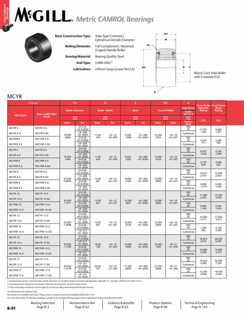
B-91
Ca
m F
oll
ow
er
Be
ari
ng
s
Metric CAMROL Bearings
B-91
MCYR
W1
E
W
RD B
R
Ro
Basic Construction Type: Yoke Type Crowned / Cylindrical Outside Diameter
Rolling Elements: Full Complement / Retained (Caged) Needle Roller
Bearing Material: Bearing Quality Steel
Seal Type: LUBRI-DISC®
Lubrication: Lithium Soap Grease NLGI #2
1. Standard bearing has a crowned roller outside diameter. For straight cylindrical outside roller diameter, add suffix “X”. Example - MCFR-35-X or MCF-35-SX.
2. Clamping torque is based on dry threads. If threads are lubricated, use half of value shown.
3. Static load rating is based on stud strength or on internal rolling element load distribution stresses.
Inch dimensions for reference only.
Not all parts are available from stock. Please contact customer service for availability (800) 626-2120.
For more information on bearing capabilities outside of our standard offering, please contact Application Engineering (800) 626-2093.
Part No. RD W B W1 RTrack Roller
Dynamic Rating
Track Roller Static Rating
Part No. E Ro LF LFT TF TFTLimiting Speed
WT
W/O Seals With LUBRI-DISC Seals
Roller Diameter Roller Width Bore Overall WidthCylindrical
W/O Seals With LUBRI-DISC Seals
Min. Clamping Diameter Outer Corner
Recommended Shaft Diameters Bearing WeightSuffix
MCYR-XLoose Fit
(for light loads) g6Light Fit
(for medium loads) h6mm inch
mm inch
mm inch
mm inch
mm inch N/lb N/lb
mm inch
mm inch
mm inch RPM kg
lbNom. Tol. Nom. Tol. Nom Tol (Ref) (Ref) Radius (Ref) (Ref) (Ref) Nom. Tol. Nom. Tol.
MCYR 5 MCYR 5 S
16.000 .6299
0/-0.05 +0/-0.0002
11.00 .433
+0/-.12 +0/-.005
5.000 .1969
+0/-.008 +0/-.0003
12.000 .4724
+0/-.18 +0/-.007
500 20 5,790
1,3026,900 1,551
MCYR 5 MCYR 5 S
11 .4
.30 .012
4.996 .1967
+0/-.008 +0/-.0003
5.000 .1968
+0/-.0 +0/-.00
13,000
.01
.02MCYR 5 X MCYR 5 SX +0/-.008
+0/-.0003 Cylindrical MCYR 5 X MCYR 5 SX
MCYRR 5 MCYRR 5 S 0/-0.05 +0/-0.0002
500 20 3,430
7713,380 760
MCYRR 5 MCYRR 5 S19,500
MCYRR 5 X MCYRR 5 SX +0/-.008 +0/-.0003 Cylindrical MCYRR 5 X MCYRR 5 SX
MCYR 6 MCYR 6 S
19.000 .7480
0/-0.05 +0/-0.0002
11.00 .433
+0/-.12 +0/-.009
6.000 .2362
+0/-.008 +0/-.0003
12.000 .4724
+0/-.18 +0/-.007
500 20 6,670
1,5008,760 1,969
MCYR 6 MCYR 6 S
13 .5
.30 .012
5.996 .2361
+0/-.008 +0/-.0003
6.000 .2362
+0/-.0 +0/-.00
10,500
.02
.04MCYR 6 X MCYR 6 SX +0/-.009
+0/-.0004 Cylindrical MCYR 6 X MCYR 6 SX
MCYRR 6 MCYRR 6 S 0/-0.05 +0/-0.0002
500 20 3,730
8394,090 920
MCYRR 6 MCYRR 6 S15,500
MCYRR 6 X MCYRR 6 SX +0/-.009 +0/-.0004 Cylindrical MCYRR 6 X MCYRR 6 SX
MCYR 8 MCYR 8 S
24.000 0.9449
0/-0.05 +0/-0.0002
14.00 .551
+0/-.12 +0/-.013
8.000 .3150
+0/-.008 +0/-.0003
15.000 .5906
+0/-.18 +0/-.007
500 20 9,610
2,16112,600 2,833
MCYR 8 MCYR 8 S
16 .6
.50 .020
7.995 .3148
+0/-.009 +0/-.0004
8.000 .3149
+0/-.0 +0/-.00
8,400
.04
.09MCYR 8 X MCYR 8 SX +0/-.009
+0/-.0004 Cylindrical MCYR 8 X MCYR 8 SX
MCYRR 8 MCYRR 8 S 0/-0.05 +0/-0.0002
500 20 5,690
1,2796,450 1,450
MCYRR 8 MCYRR 8 S12,500
MCYRR 8 X MCYRR 8 SX +0/-.009 +0/-.0004 Cylindrical MCYRR 8 X MCYRR 8 SX
MCYR 10 MCYR 10 S
30.000 1.1811
0/-0.05 +0/-0.0002
14.00 .551
+0/-.12 +0/-.017
10.000 .3937
+0/-.008 +0/-.0003
15.000 .5906
+0/-.18 +0/-.007
500 20 11,080
2,49115,300 3,440
MCYR 10 MCYR 10 S
19 .7
1.00 .039
9.995 .3935
+0/-.009 +0/-.0004
10.000 .3937
+0/-.0 +0/-.00
6,400
.06
.13MCYR 10 X MCYR 10 SX +0/-.009
+0/-.0004 Cylindrical MCYR 10 X MCYR 10 SX
MCYRR 10 MCYRR 10 S 0/-0.05 +0/-0.0002
500 20 6,860
1,5428,050 1,810
MCYRR 10 MCYRR 10 S9,600
MCYRR 10 X MCYRR 10 SX +0/-.009 +0/-.0004 Cylindrical MCYRR 10 X MCYRR 10 SX
MCYR 12 MCYR 12 S
32.000 1.2598
0/-0.05 +0/-0.0002
14.00 .551
+0/-.12 +0/-.021
12.000 .4724
+0/-.008 +0/-.0003
15.000 .5906
+0/-.18 +0/-.007
500 20 12,060
2,71117,400 3,912
MCYR 12 MCYR 12 S
21 .8
1.00 .039
11.994 .4722
+0/-.011 +0/-.0004
12.000 .4724
+0/-.0 +0/-.00
6,400
.07
.15MCYR 12 X MCYR 12 SX +0/-.011
+0/-.0004 Cylindrical MCYR 12 X MCYR 12 SX
MCYRR 12 MCYRR 12 S 0/-0.05 +0/-0.0002
500 20 1,260
2839,120 2,050
MCYRR 12 MCYRR 12 S9,600
MCYRR 12 X MCYRR 12 SX +0/-.011 +0/-.0004 Cylindrical MCYRR 12 X MCYRR 12 SX
MCYR 15 MCYR 15 S
35.000 1.3780
0/-0.05 +0/-0.0002
18.00 .709
+0/-.12 +0/-.025
15.000 .5906
+0/-.008 +0/-.0003
19.000 .7480
+0/-.21 +0/-.008
500 20 16,970
3,81528,500 6,407
MCYR 15 MCYR 15 S
24 0.9
1.00 .039
14.994 .5903
+0/-.011 +0/-.0004
15.000 .5905
+0/-.0 +0/-.00
4,200
.10
.22MCYR 15 X MCYR 15 SX +0/-.011
+0/-.0004 Cylindrical MCYR 15 X MCYR 15 SX
MCYRR 15 MCYRR 15 S 0/-0.05 +0/-0.0002
500 20 10,890
2,44815,900 3,575
MCYRR 15 MCYRR 15 S6,300
MCYRR 15 X MCYRR 15 SX +0/-.011 +0/-.0004 Cylindrical MCYRR 15 X MCYRR 15 SX
MCYR 17 MCYR 17 S
40.000 1.5748
0/-0.05 +0/-0.0002
20.00 .787
+0/-.12 +0/-.029
17.000 .6693
+0/-.008 +0/-.0003
21.000 .8268
+0/-.21 +0/-.008
500 20 19,420
4,36632,200 7,239
MCYR 17 MCYR 17 S
27 1.1
1.50 .059
16.994 .6691
+0/-.011 +0/-.0004
17.000 .6692
+0/-.0 +0/-.00
3,300
.15
.33MCYR 17 X MCYR 17 SX +0/-.011
+0/-.0004 Cylindrical MCYR 17 X MCYR 17 SX
MCYRR 17 MCYRR 17 S 0/-0.05 +0/-0.0002
500 20 13,340
2,99919,700 4,429
MCYRR 17 MCYRR 17 S5,000
MCYRR 17 X MCYRR 17 SX +0/-.011 +0/-.0004 Cylindrical MCYRR 17 X MCYRR 17 SX
Metric Cam Yoke Roller with Crowned O.D.
Bearing SelectionPage B-3
Nomenclature AidPage B-62
Features & BenefitsPage B-63
Product OptionsPage B-66
Technical EngineeringPage B-143
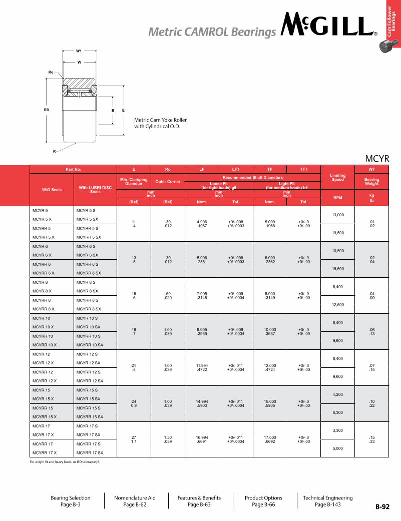
B-92
Ca
m F
oll
ow
er
Be
ari
ng
s
Metric CAMROL Bearings
B-92
MCYR
BRD E
W
W1
Ro
R
For a tight fit and heavy loads, us ISO tolerance J6.
Part No. RD W B W1 RTrack Roller
Dynamic Rating
Track Roller Static Rating
Part No. E Ro LF LFT TF TFTLimiting Speed
WT
W/O Seals With LUBRI-DISC Seals
Roller Diameter Roller Width Bore Overall WidthCylindrical
W/O Seals With LUBRI-DISC Seals
Min. Clamping Diameter Outer Corner
Recommended Shaft Diameters Bearing WeightSuffix
MCYR-XLoose Fit
(for light loads) g6Light Fit
(for medium loads) h6mm inch
mm inch
mm inch
mm inch
mm inch N/lb N/lb
mm inch
mm inch
mm inch RPM kg
lbNom. Tol. Nom. Tol. Nom Tol (Ref) (Ref) Radius (Ref) (Ref) (Ref) Nom. Tol. Nom. Tol.
MCYR 5 MCYR 5 S
16.000 .6299
0/-0.05 +0/-0.0002
11.00 .433
+0/-.12 +0/-.005
5.000 .1969
+0/-.008 +0/-.0003
12.000 .4724
+0/-.18 +0/-.007
500 20 5,790
1,3026,900 1,551
MCYR 5 MCYR 5 S
11 .4
.30 .012
4.996 .1967
+0/-.008 +0/-.0003
5.000 .1968
+0/-.0 +0/-.00
13,000
.01
.02MCYR 5 X MCYR 5 SX +0/-.008
+0/-.0003 Cylindrical MCYR 5 X MCYR 5 SX
MCYRR 5 MCYRR 5 S 0/-0.05 +0/-0.0002
500 20 3,430
7713,380 760
MCYRR 5 MCYRR 5 S19,500
MCYRR 5 X MCYRR 5 SX +0/-.008 +0/-.0003 Cylindrical MCYRR 5 X MCYRR 5 SX
MCYR 6 MCYR 6 S
19.000 .7480
0/-0.05 +0/-0.0002
11.00 .433
+0/-.12 +0/-.009
6.000 .2362
+0/-.008 +0/-.0003
12.000 .4724
+0/-.18 +0/-.007
500 20 6,670
1,5008,760 1,969
MCYR 6 MCYR 6 S
13 .5
.30 .012
5.996 .2361
+0/-.008 +0/-.0003
6.000 .2362
+0/-.0 +0/-.00
10,500
.02
.04MCYR 6 X MCYR 6 SX +0/-.009
+0/-.0004 Cylindrical MCYR 6 X MCYR 6 SX
MCYRR 6 MCYRR 6 S 0/-0.05 +0/-0.0002
500 20 3,730
8394,090 920
MCYRR 6 MCYRR 6 S15,500
MCYRR 6 X MCYRR 6 SX +0/-.009 +0/-.0004 Cylindrical MCYRR 6 X MCYRR 6 SX
MCYR 8 MCYR 8 S
24.000 0.9449
0/-0.05 +0/-0.0002
14.00 .551
+0/-.12 +0/-.013
8.000 .3150
+0/-.008 +0/-.0003
15.000 .5906
+0/-.18 +0/-.007
500 20 9,610
2,16112,600 2,833
MCYR 8 MCYR 8 S
16 .6
.50 .020
7.995 .3148
+0/-.009 +0/-.0004
8.000 .3149
+0/-.0 +0/-.00
8,400
.04
.09MCYR 8 X MCYR 8 SX +0/-.009
+0/-.0004 Cylindrical MCYR 8 X MCYR 8 SX
MCYRR 8 MCYRR 8 S 0/-0.05 +0/-0.0002
500 20 5,690
1,2796,450 1,450
MCYRR 8 MCYRR 8 S12,500
MCYRR 8 X MCYRR 8 SX +0/-.009 +0/-.0004 Cylindrical MCYRR 8 X MCYRR 8 SX
MCYR 10 MCYR 10 S
30.000 1.1811
0/-0.05 +0/-0.0002
14.00 .551
+0/-.12 +0/-.017
10.000 .3937
+0/-.008 +0/-.0003
15.000 .5906
+0/-.18 +0/-.007
500 20 11,080
2,49115,300 3,440
MCYR 10 MCYR 10 S
19 .7
1.00 .039
9.995 .3935
+0/-.009 +0/-.0004
10.000 .3937
+0/-.0 +0/-.00
6,400
.06
.13MCYR 10 X MCYR 10 SX +0/-.009
+0/-.0004 Cylindrical MCYR 10 X MCYR 10 SX
MCYRR 10 MCYRR 10 S 0/-0.05 +0/-0.0002
500 20 6,860
1,5428,050 1,810
MCYRR 10 MCYRR 10 S9,600
MCYRR 10 X MCYRR 10 SX +0/-.009 +0/-.0004 Cylindrical MCYRR 10 X MCYRR 10 SX
MCYR 12 MCYR 12 S
32.000 1.2598
0/-0.05 +0/-0.0002
14.00 .551
+0/-.12 +0/-.021
12.000 .4724
+0/-.008 +0/-.0003
15.000 .5906
+0/-.18 +0/-.007
500 20 12,060
2,71117,400 3,912
MCYR 12 MCYR 12 S
21 .8
1.00 .039
11.994 .4722
+0/-.011 +0/-.0004
12.000 .4724
+0/-.0 +0/-.00
6,400
.07
.15MCYR 12 X MCYR 12 SX +0/-.011
+0/-.0004 Cylindrical MCYR 12 X MCYR 12 SX
MCYRR 12 MCYRR 12 S 0/-0.05 +0/-0.0002
500 20 1,260
2839,120 2,050
MCYRR 12 MCYRR 12 S9,600
MCYRR 12 X MCYRR 12 SX +0/-.011 +0/-.0004 Cylindrical MCYRR 12 X MCYRR 12 SX
MCYR 15 MCYR 15 S
35.000 1.3780
0/-0.05 +0/-0.0002
18.00 .709
+0/-.12 +0/-.025
15.000 .5906
+0/-.008 +0/-.0003
19.000 .7480
+0/-.21 +0/-.008
500 20 16,970
3,81528,500 6,407
MCYR 15 MCYR 15 S
24 0.9
1.00 .039
14.994 .5903
+0/-.011 +0/-.0004
15.000 .5905
+0/-.0 +0/-.00
4,200
.10
.22MCYR 15 X MCYR 15 SX +0/-.011
+0/-.0004 Cylindrical MCYR 15 X MCYR 15 SX
MCYRR 15 MCYRR 15 S 0/-0.05 +0/-0.0002
500 20 10,890
2,44815,900 3,575
MCYRR 15 MCYRR 15 S6,300
MCYRR 15 X MCYRR 15 SX +0/-.011 +0/-.0004 Cylindrical MCYRR 15 X MCYRR 15 SX
MCYR 17 MCYR 17 S
40.000 1.5748
0/-0.05 +0/-0.0002
20.00 .787
+0/-.12 +0/-.029
17.000 .6693
+0/-.008 +0/-.0003
21.000 .8268
+0/-.21 +0/-.008
500 20 19,420
4,36632,200 7,239
MCYR 17 MCYR 17 S
27 1.1
1.50 .059
16.994 .6691
+0/-.011 +0/-.0004
17.000 .6692
+0/-.0 +0/-.00
3,300
.15
.33MCYR 17 X MCYR 17 SX +0/-.011
+0/-.0004 Cylindrical MCYR 17 X MCYR 17 SX
MCYRR 17 MCYRR 17 S 0/-0.05 +0/-0.0002
500 20 13,340
2,99919,700 4,429
MCYRR 17 MCYRR 17 S5,000
MCYRR 17 X MCYRR 17 SX +0/-.011 +0/-.0004 Cylindrical MCYRR 17 X MCYRR 17 SX
Metric Cam Yoke Roller with Cylindrical O.D.
Bearing SelectionPage B-3
Nomenclature AidPage B-62
Features & BenefitsPage B-63
Product OptionsPage B-66
Technical EngineeringPage B-143
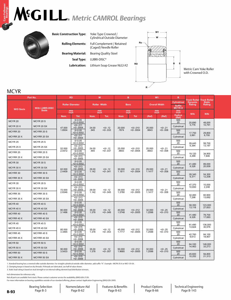
B-93
Ca
m F
oll
ow
er
Be
ari
ng
s
Metric CAMROL Bearings
B-93
MCYR
Basic Construction Type: Yoke Type Crowned / Cylindrical Outside Diameter
Rolling Elements: Full Complement / Retained (Caged) Needle Roller
Bearing Material: Bearing Quality Steel
Seal Type: LUBRI-DISC®
Lubrication: Lithium Soap Grease NLGI #2
1. Standard bearing has a crowned roller outside diameter. For straight cylindrical outside roller diameter, add suffix “X”. Example - MCFR-35-X or MCF-35-SX.
2. Clamping torque is based on dry threads. If threads are lubricated, use half of value shown.
3. Static load rating is based on stud strength or on internal rolling element load distribution stresses.
Inch dimensions for reference only.
Not all parts are available from stock. Please contact customer service for availability (800) 626-2120.
For more information on bearing capabilities outside of our standard offering, please contact Application Engineering (800) 626-2093.
Part No. RD W B W1 RTrack Roller
Dynamic Rating
Track Roller Static Rating
Part No. E Ro LF LFT TF TFTLimiting Speed
WT
W/O Seals With LUBRI-DISC Seals
Roller Diameter Roller Width Bore Overall WidthCylindrical
W/O Seals With LUBRI-DISC Seals
Min. Clamping Diameter Outer Corner
Recommended Shaft Diameters Bearing WeightSuffix
MCYR-XLoose Fit
(for light loads) g6Light Fit
(for medium loads) h6mm inch
mm inch
mm inch
mm inch
mm inch N/lb N/lb
mm inch
mm inch
mm inch RPM kg
lbNom. Tol. Nom. Tol. Nom Tol (Ref) (Ref) Radius (Ref) (Ref) (Ref) Nom. Tol. Nom. Tol.
MCYR 20 MCYR 20 S
47.000 1.8504
0/-0.05 +0/-0.0002
24.00 .945
+0/-.12 +0/-.033
20.000 .7874
+0/-.010 +0/-.0004
25.000 .9843
+0/-.21 +0/-.008
500 20 25,690
5,77648,000 10,791
MCYR 20 MCYR 20 S
30 1.2
1.50 .059
19.993 .7871
+0/-.013 +0/-.0005
20.000 .7874
+0/-.0 +0/-.00
2,600
.25
.55MCYR 20 X MCYR 20 SX +0/-.011
+0/-.0004 Cylindrical MCYR 20 X MCYR 20 SX
MCYRR 20 MCYRR 20 S 0/-0.05 +0/-0.0002
500 20 17,750
3,99129,800 6,700
MCYRR 20 MCYRR 20 S3,900
MCYRR 20 X MCYRR 20 SX +0/-.011 +0/-.0004 Cylindrical MCYRR 20 X MCYRR 20 SX
MCYR 25 MCYR 25 S
52.000 2.0472
0/-0.05 +0/-0.0002
24.00 .945
+0/-.12 +0/-.037
25.000 .9843
+0/-.010 +0/-.0004
25.000 .9843
+0/-.21 +0/-.008
500 20 28,440
6,39458,700 13,197
MCYR 25 MCYR 25 S
36 1.4
1.50 .059
24.993 .9840
+0/-.013 +0/-.0005
25.000 .9842
+0/-.0 +0/-.00
2,600
.29
.64MCYR 25 X MCYR 25 SX +0/-.013
+0/-.0005 Cylindrical MCYR 25 X MCYR 25 SX
MCYRR 25 MCYRR 25 S 0/-0.05 +0/-0.0002
500 20 19,120
4,29934,900 7,846
MCYRR 25 MCYRR 25 S3,900
MCYRR 25 X MCYRR 25 SX +0/-.013 +0/-.0005 Cylindrical MCYRR 25 X MCYRR 25 SX
MCYR 30 MCYR 30 S
62.000 2.4409
0/-0.05 +0/-0.0002
29.00 1.142
+0/-.12 +0/-.041
30.000 1.1811
+0/-.010 +0/-.0004
29.000 1.1417
+0/-.21 +0/-.008
500 20 41,480
9,32689,000 20,009
MCYR 30 MCYR 30 S
44 1.7
2.00 .079
29.993 1.1808
+0/-.013 +0/-.0005
30.000 1.1811
+0/-.0 +0/-.00
2,100
.47 1.04
MCYR 30 X MCYR 30 SX +0/-.013 +0/-.0005 Cylindrical MCYR 30 X MCYR 30 SX
MCYRR 30 MCYRR 30 S 0/-0.05 +0/-0.0002
500 20 28,340
6,37154,300 12,208
MCYRR 30 MCYRR 30 S3,100
MCYRR 30 X MCYRR 30 SX +0/-.013 +0/-.0005 Cylindrical MCYRR 30 X MCYRR 30 SX
MCYR 35 MCYR 35 S
72.000 2.8346
0/-0.05 +0/-0.0002
29.00 1.142
+0/-.12 +0/-.045
35.000 1.3780
+0/-.012 +0/-.0005
29.000 1.1417
+0/-.21 +0/-.008
500 20 47,370
10,65010,000 2,248
MCYR 35 MCYR 35 S
52 2.0
2.00 .079
34.991 1.3776
+0/-.016 +0/-.0006
35.000 1.3779
+0/-.0 +0/-.00
2,100
.64 1.41
MCYR 35 X MCYR 35 SX +0/-.013 +0/-.0005 Cylindrical MCYR 35 X MCYR 35 SX
MCYRR 35 MCYRR 35 S 0/-0.05 +0/-0.0002
500 20 32,460
7,29860,900 13,692
MCYRR 35 MCYRR 35 S3,100
MCYRR 35 X MCYRR 35 SX +0/-.013 +0/-.0005 Cylindrical MCYRR 35 X MCYRR 35 SX
MCYR 40 MCYR 40 S
80.000 3.1496
0/-0.05 +0/-0.0002
35.00 1.378
+0/-.12 +0/-.049
40.000 1.5748
+0/-.012 +0/-.0005
32.000 1.2598
+0/-.25 +0/-.010
500 20 58,350
13,118123,000 27,653
MCYR 40 MCYR 40 S
58 2.3
2.00 .079
39.991 1.5744
+0/-.016 +0/-.0006
40.000 1.5748
+0/-.0 +0/-.00
1,500.84 1.84
MCYR 40 X MCYR 40 SX +0/-.015 +0/-.0006 Cylindrical MCYR 40 X MCYR 40 SX
MCYRR 40 MCYRR 40 S 0/-0.05 +0/-0.0002
500 20 41,480
9,32678,700 17,693
MCYRR 40 MCYRR 40 S2,200
MCYRR 40 X MCYRR 40 SX +0/-.015 +0/-.0006 Cylindrical MCYRR 40 X MCYRR 40 SX
MCYR 45 MCYR 45 S
85.000 3.3465
0/-0.05 +0/-0.0002
35.00 1.378
+0/-.12 +0/-.053
45.000 1.7717
+0/-.012 +0/-.0005
32.000 1.2598
+0/-.25 +0/-.010
500 20 61,490
13,824136,000 30,576
MCYR 45 MCYR 45 S
63 2.5
2.00 .079
44.991 1.7713
+0/-.016 +0/-.0006
45.000 1.7716
+0/-.0 +0/-.00
1,500.90 1.99
MCYR 45 X MCYR 45 SX +0/-.015 +0/-.0006 Cylindrical MCYR 45 X MCYR 45 SX
MCYRR 45 MCYRR 45 S 0/-0.05 +0/-0.0002
500 20 42,760
9,61384,100 18,907
MCYRR 45 MCYRR 45 S2,200
MCYRR 45 X MCYRR 45 SX +0/-.015 +0/-.0006 Cylindrical MCYRR 45 X MCYRR 45 SX
MCYR 50 MCYR 50 S
90.000 3.5433
0/-0.05 +0/-0.0002
35.00 1.378
+0/-.12 +0/-.057
50.000 1.9685
+0/-.012 +0/-.0005
32.000 1.2598
+0/-.25 +0/-.010
500 20 64,330
14,463148,000 33,273
MCYR 50 MCYR 50 S
68 2.7
2.00 .079
45.991 1.8107
+0/-.016 +0/-.0006
50.000 1.9685
+0/-.0 +0/-.00
1,500.97 2.14
MCYR 50 X MCYR 50 SX +0/-.015 +0/-.0006 Cylindrical MCYR 50 X MCYR 50 SX
MCYRR 50 MCYRR 50 S 0/-0.05 +0/-0.0002
500 20 45,600
10,25294,800 21,313
MCYRR 50 MCYRR 50 S2,200
MCYRR 50 X MCYRR 50 SX +0/-.015 +0/-.0006 Cylindrical MCYRR 50 X MCYRR 50 SX
W1
E
W
RD B
R
Ro
Metric Cam Yoke Roller with Crowned O.D.
Bearing SelectionPage B-3
Nomenclature AidPage B-62
Features & BenefitsPage B-63
Product OptionsPage B-66
Technical EngineeringPage B-143
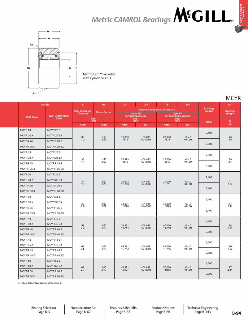
B-94
Ca
m F
oll
ow
er
Be
ari
ng
s
Metric CAMROL Bearings
B-94
MCYR
For a tight fit and heavy loads, us ISO tolerance J6.
Part No. RD W B W1 RTrack Roller
Dynamic Rating
Track Roller Static Rating
Part No. E Ro LF LFT TF TFTLimiting Speed
WT
W/O Seals With LUBRI-DISC Seals
Roller Diameter Roller Width Bore Overall WidthCylindrical
W/O Seals With LUBRI-DISC Seals
Min. Clamping Diameter Outer Corner
Recommended Shaft Diameters Bearing WeightSuffix
MCYR-XLoose Fit
(for light loads) g6Light Fit
(for medium loads) h6mm inch
mm inch
mm inch
mm inch
mm inch N/lb N/lb
mm inch
mm inch
mm inch RPM kg
lbNom. Tol. Nom. Tol. Nom Tol (Ref) (Ref) Radius (Ref) (Ref) (Ref) Nom. Tol. Nom. Tol.
MCYR 20 MCYR 20 S
47.000 1.8504
0/-0.05 +0/-0.0002
24.00 .945
+0/-.12 +0/-.033
20.000 .7874
+0/-.010 +0/-.0004
25.000 .9843
+0/-.21 +0/-.008
500 20 25,690
5,77648,000 10,791
MCYR 20 MCYR 20 S
30 1.2
1.50 .059
19.993 .7871
+0/-.013 +0/-.0005
20.000 .7874
+0/-.0 +0/-.00
2,600
.25
.55MCYR 20 X MCYR 20 SX +0/-.011
+0/-.0004 Cylindrical MCYR 20 X MCYR 20 SX
MCYRR 20 MCYRR 20 S 0/-0.05 +0/-0.0002
500 20 17,750
3,99129,800 6,700
MCYRR 20 MCYRR 20 S3,900
MCYRR 20 X MCYRR 20 SX +0/-.011 +0/-.0004 Cylindrical MCYRR 20 X MCYRR 20 SX
MCYR 25 MCYR 25 S
52.000 2.0472
0/-0.05 +0/-0.0002
24.00 .945
+0/-.12 +0/-.037
25.000 .9843
+0/-.010 +0/-.0004
25.000 .9843
+0/-.21 +0/-.008
500 20 28,440
6,39458,700 13,197
MCYR 25 MCYR 25 S
36 1.4
1.50 .059
24.993 .9840
+0/-.013 +0/-.0005
25.000 .9842
+0/-.0 +0/-.00
2,600
.29
.64MCYR 25 X MCYR 25 SX +0/-.013
+0/-.0005 Cylindrical MCYR 25 X MCYR 25 SX
MCYRR 25 MCYRR 25 S 0/-0.05 +0/-0.0002
500 20 19,120
4,29934,900 7,846
MCYRR 25 MCYRR 25 S3,900
MCYRR 25 X MCYRR 25 SX +0/-.013 +0/-.0005 Cylindrical MCYRR 25 X MCYRR 25 SX
MCYR 30 MCYR 30 S
62.000 2.4409
0/-0.05 +0/-0.0002
29.00 1.142
+0/-.12 +0/-.041
30.000 1.1811
+0/-.010 +0/-.0004
29.000 1.1417
+0/-.21 +0/-.008
500 20 41,480
9,32689,000 20,009
MCYR 30 MCYR 30 S
44 1.7
2.00 .079
29.993 1.1808
+0/-.013 +0/-.0005
30.000 1.1811
+0/-.0 +0/-.00
2,100
.47 1.04
MCYR 30 X MCYR 30 SX +0/-.013 +0/-.0005 Cylindrical MCYR 30 X MCYR 30 SX
MCYRR 30 MCYRR 30 S 0/-0.05 +0/-0.0002
500 20 28,340
6,37154,300 12,208
MCYRR 30 MCYRR 30 S3,100
MCYRR 30 X MCYRR 30 SX +0/-.013 +0/-.0005 Cylindrical MCYRR 30 X MCYRR 30 SX
MCYR 35 MCYR 35 S
72.000 2.8346
0/-0.05 +0/-0.0002
29.00 1.142
+0/-.12 +0/-.045
35.000 1.3780
+0/-.012 +0/-.0005
29.000 1.1417
+0/-.21 +0/-.008
500 20 47,370
10,65010,000 2,248
MCYR 35 MCYR 35 S
52 2.0
2.00 .079
34.991 1.3776
+0/-.016 +0/-.0006
35.000 1.3779
+0/-.0 +0/-.00
2,100
.64 1.41
MCYR 35 X MCYR 35 SX +0/-.013 +0/-.0005 Cylindrical MCYR 35 X MCYR 35 SX
MCYRR 35 MCYRR 35 S 0/-0.05 +0/-0.0002
500 20 32,460
7,29860,900 13,692
MCYRR 35 MCYRR 35 S3,100
MCYRR 35 X MCYRR 35 SX +0/-.013 +0/-.0005 Cylindrical MCYRR 35 X MCYRR 35 SX
MCYR 40 MCYR 40 S
80.000 3.1496
0/-0.05 +0/-0.0002
35.00 1.378
+0/-.12 +0/-.049
40.000 1.5748
+0/-.012 +0/-.0005
32.000 1.2598
+0/-.25 +0/-.010
500 20 58,350
13,118123,000 27,653
MCYR 40 MCYR 40 S
58 2.3
2.00 .079
39.991 1.5744
+0/-.016 +0/-.0006
40.000 1.5748
+0/-.0 +0/-.00
1,500.84
1.84MCYR 40 X MCYR 40 SX +0/-.015
+0/-.0006 Cylindrical MCYR 40 X MCYR 40 SX
MCYRR 40 MCYRR 40 S 0/-0.05 +0/-0.0002
500 20 41,480
9,32678,700 17,693
MCYRR 40 MCYRR 40 S2,200
MCYRR 40 X MCYRR 40 SX +0/-.015 +0/-.0006 Cylindrical MCYRR 40 X MCYRR 40 SX
MCYR 45 MCYR 45 S
85.000 3.3465
0/-0.05 +0/-0.0002
35.00 1.378
+0/-.12 +0/-.053
45.000 1.7717
+0/-.012 +0/-.0005
32.000 1.2598
+0/-.25 +0/-.010
500 20 61,490
13,824136,000 30,576
MCYR 45 MCYR 45 S
63 2.5
2.00 .079
44.991 1.7713
+0/-.016 +0/-.0006
45.000 1.7716
+0/-.0 +0/-.00
1,500.90
1.99MCYR 45 X MCYR 45 SX +0/-.015
+0/-.0006 Cylindrical MCYR 45 X MCYR 45 SX
MCYRR 45 MCYRR 45 S 0/-0.05 +0/-0.0002
500 20 42,760
9,61384,100 18,907
MCYRR 45 MCYRR 45 S2,200
MCYRR 45 X MCYRR 45 SX +0/-.015 +0/-.0006 Cylindrical MCYRR 45 X MCYRR 45 SX
MCYR 50 MCYR 50 S
90.000 3.5433
0/-0.05 +0/-0.0002
35.00 1.378
+0/-.12 +0/-.057
50.000 1.9685
+0/-.012 +0/-.0005
32.000 1.2598
+0/-.25 +0/-.010
500 20 64,330
14,463148,000 33,273
MCYR 50 MCYR 50 S
68 2.7
2.00 .079
45.991 1.8107
+0/-.016 +0/-.0006
50.000 1.9685
+0/-.0 +0/-.00
1,500.97
2.14MCYR 50 X MCYR 50 SX +0/-.015
+0/-.0006 Cylindrical MCYR 50 X MCYR 50 SX
MCYRR 50 MCYRR 50 S 0/-0.05 +0/-0.0002
500 20 45,600
10,25294,800 21,313
MCYRR 50 MCYRR 50 S2,200
MCYRR 50 X MCYRR 50 SX +0/-.015 +0/-.0006 Cylindrical MCYRR 50 X MCYRR 50 SX
BRD E
W
W1
Ro
R
Metric Cam Yoke Roller with Cylindrical O.D.
Bearing SelectionPage B-3
Nomenclature AidPage B-62
Features & BenefitsPage B-63
Product OptionsPage B-66
Technical EngineeringPage B-143
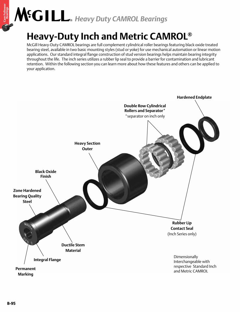
B-95
Ca
m F
oll
ow
er
Be
ari
ng
s
Heavy Duty CAMROL Bearings
B-95
Heavy-Duty Inch and Metric CAMROL®
McGill Heavy-Duty CAMROL bearings are full complement cylindrical roller bearings featuring black oxide treated bearing steel, available in two basic mounting styles (stud or yoke) for use mechanical automation or linear motion applications. Our standard integral flange construction of stud version bearings helps maintain bearing integrity throughout the life. The inch series utilizes a rubber lip seal to provide a barrier for contamination and lubricant retention. Within the following section you can learn more about how these features and others can be applied to your application.
Double Row Cylindrical Rollers and Separator**separator on inch only
Heavy Section Outer
Black Oxide Finish
PermanentMarking
Ductile StemMaterial
Rubber LipContact Seal
(Inch Series only)
Integral Flange
Zone HardenedBearing Quality
Steel
Dimensionally Interchangeable with respective Standard Inch and Metric CAMROL
Hardened Endplate
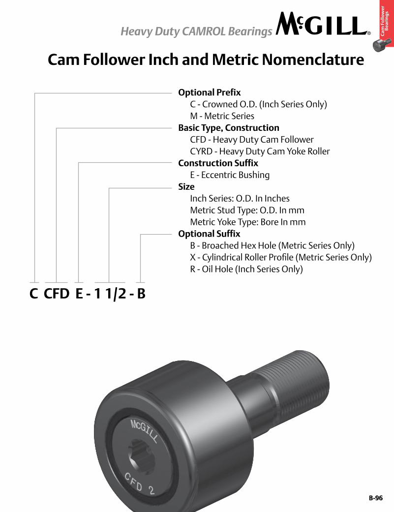
B-96
Ca
m F
oll
ow
er
Be
ari
ng
s
Heavy Duty CAMROL Bearings
B-96
Cam Follower Inch and Metric Nomenclature
Optional Prefix C - Crowned O.D. (Inch Series Only) M - Metric SeriesBasic Type, Construction CFD - Heavy Duty Cam Follower CYRD - Heavy Duty Cam Yoke RollerConstruction Suffix E - Eccentric BushingSize Inch Series: O.D. In Inches Metric Stud Type: O.D. In mm Metric Yoke Type: Bore In mmOptional Suffix B - Broached Hex Hole (Metric Series Only) X - Cylindrical Roller Profile (Metric Series Only) R - Oil Hole (Inch Series Only)
C CFD E - 1 1/2 - B
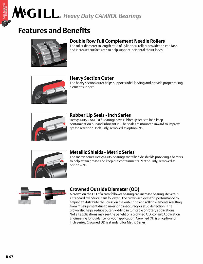
B-97
Ca
m F
oll
ow
er
Be
ari
ng
s
Heavy Duty CAMROL Bearings
B-97
Features and BenefitsDouble Row Full Complement Needle RollersThe roller diameter to length ratio of Cylindrical rollers provides an end face and increases surface area to help support incidental thrust loads.
Rubber Lip Seals - Inch SeriesHeavy-Duty CAMROL® Bearings have rubber lip seals to help keep contamination our and lubricant in. The seals are mounted inward to improve grease retention. Inch Only, removed as option- NS
Heavy Section OuterThe heavy section outer helps support radial loading and provide proper rolling element support.
Metallic Shields - Metric SeriesThe metric series Heavy-Duty bearings metallic side shields providing a barriers to help retain grease and keep out containments. Metric Only, removed as option – NS
Crowned Outside Diameter (OD)A crown on the OD of a cam follower bearing can increase bearing life versus a standard cylindrical cam follower. The crown achieves this performance by helping to distribute the stress on the outer ring and rolling elements resulting from misalignment due to mounting inaccuracy or stud deflection. The crown also helps reduce outer skidding in turntable or rotary applications. Not all applications may see the benefit of a crowned OD, consult Application Engineering for guidance for your application. Crowned OD is an option for Inch Series. Crowned OD is standard for Metric Series.
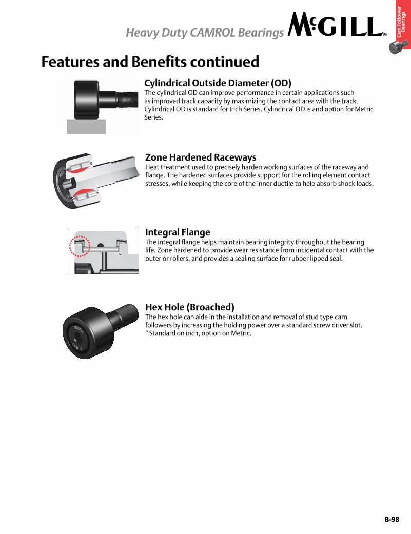
B-98
Ca
m F
oll
ow
er
Be
ari
ng
s
Heavy Duty CAMROL Bearings
B-98
Cylindrical Outside Diameter (OD)The cylindrical OD can improve performance in certain applications such as improved track capacity by maximizing the contact area with the track. Cylindrical OD is standard for Inch Series. Cylindrical OD is and option for Metric Series.
Features and Benefits continued
Zone Hardened RacewaysHeat treatment used to precisely harden working surfaces of the raceway and flange. The hardened surfaces provide support for the rolling element contact stresses, while keeping the core of the inner ductile to help absorb shock loads.
Integral FlangeThe integral flange helps maintain bearing integrity throughout the bearing life. Zone hardened to provide wear resistance from incidental contact with the outer or rollers, and provides a sealing surface for rubber lipped seal.
Hex Hole (Broached)The hex hole can aide in the installation and removal of stud type cam followers by increasing the holding power over a standard screw driver slot. *Standard on inch, option on Metric.

B-99
Ca
m F
oll
ow
er
Be
ari
ng
s
Heavy Duty CAMROL Bearings
B-99
Features and Benefits continuedFeatures and Benefits
Factory Grease FillThe cam follower and cam yoke roller bearings are factory lubricated with a medium temperature grease. Contact Application Engineering when application conditions require special lubricants.
Black Oxide FinishBearings have a black oxide finish on all external surfaces.
Lubrication ReservoirThe inch series heavy-Duty bearings incorporate a spacer, resulting in an increased lubricant reservoir. Inch only
Hardened Endplate Similar to the flange, the endplate must provide a contact surface for the seal and resist wear from incidental contact with the outer or rollers.
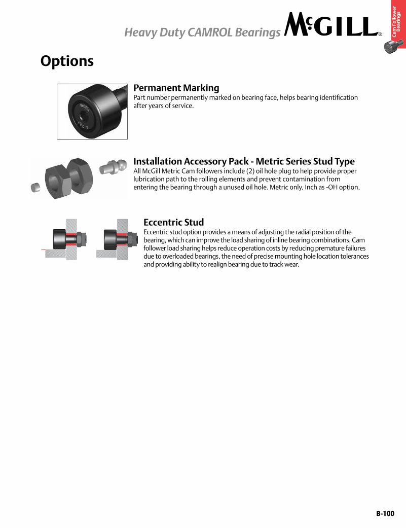
B-100
Ca
m F
oll
ow
er
Be
ari
ng
s
Heavy Duty CAMROL Bearings
B-100
Options
Eccentric StudEccentric stud option provides a means of adjusting the radial position of the bearing, which can improve the load sharing of inline bearing combinations. Cam follower load sharing helps reduce operation costs by reducing premature failures due to overloaded bearings, the need of precise mounting hole location tolerances and providing ability to realign bearing due to track wear.
Installation Accessory Pack - Metric Series Stud TypeAll McGill Metric Cam followers include (2) oil hole plug to help provide proper lubrication path to the rolling elements and prevent contamination from entering the bearing through a unused oil hole. Metric only, Inch as -OH option,
Permanent MarkingPart number permanently marked on bearing face, helps bearing identification after years of service.

B-101
Ca
m F
oll
ow
er
Be
ari
ng
s
Heavy Duty CAMROL Bearings
B-101
Additional Options
THBThreaded axial oil hole on both ends of cam follower stud. Available with all screw driver slot cam followers or broached cam followers over 3”.
ALGAnnular lubrication groove at cam follower stem radial lubrication hole.
BHTBroached (Hex) hole at threaded end of cam follower stud.
THFThreaded axial lubrication hole at flanged end of cam follower stud. Available with all screw driver slot cam followers or broached cam followers over 3”.
THTThreaded axial lubrication hole at threaded end of cam follower stud.
B-102
Ca
m F
oll
ow
er
Be
ari
ng
s
Heavy Duty CAMROL Bearings
B-102
Custom Capabilities• Customerspecifiedfactorygreasefill
• Greasefittinginstalled
• Studorthreadlengthmodifications
• Rollerdiametervariationsortolerances
• Camfollowersgroupedormatcheddiametertolerance/runoutsets
• Customengineeredtoorderdesigns
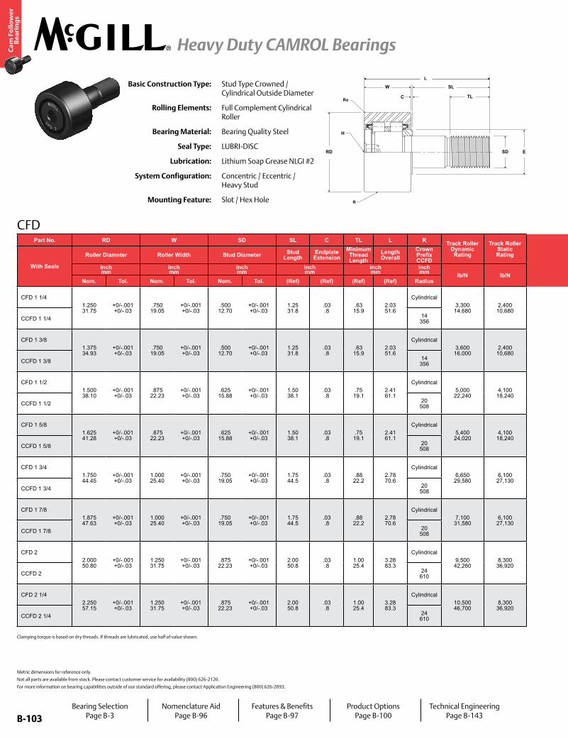
B-103
Ca
m F
oll
ow
er
Be
ari
ng
s
Heavy Duty CAMROL Bearings
B-103
CFD
Basic Construction Type: Stud Type Crowned / Cylindrical Outside Diameter
Rolling Elements: Full Complement Cylindrical Roller
Bearing Material: Bearing Quality Steel
Seal Type: LUBRI-DISC
Lubrication: Lithium Soap Grease NLGI #2
System Configuration: Concentric / Eccentric / Heavy Stud
Mounting Feature: Slot / Hex Hole
Metric dimensions for reference only.
Not all parts are available from stock. Please contact customer service for availability (800) 626-2120.
For more information on bearing capabilities outside of our standard offering, please contact Application Engineering (800) 626-2093.
Part No. RD W SD SL C TL L R Track Roller Dynamic Rating
Track Roller Static Rating
Part No. H E Ro Housing Bore
DiameterThread Type
Clamping TorqueWT
With Seals
Roller Diameter Roller Width Stud Diameter Stud Length
Endplate Extension
Minimum Thread Length
Length Overall
Crown Prefix CCFD
With Seals
Hex Hole Min. Clamping Diameter Corner Bearing Weight
inch mm
inch mm
inch mm
inch mm
inch mm
inch mm lb/N lb/N
inch mm
inch mm
inch mm in-lb
NmlbkgNom. Tol. Nom. Tol. Nom. Tol. (Ref) (Ref) (Ref) (Ref) Radius Size (Ref) (Ref) Nom. Tol.
CFD 1 1/41.250 31.75
+0/-.001 +0/-.03
.750 19.05
+0/-.001 +0/-.03
.500 12.70
+0/-.001 +0/-.03
1.25 31.8
.03 .8
.63 15.9
2.03 51.6
Cylindrical3,300 14,680
2,400 10,680
CFD 1 1/4.25 6.4
.98 25.0
.03 .8
.5003 12.708
+.0002/-.0003 +.0005/-.0008 1/2-20 350
40.29 .13
CCFD 1 1/4 14 356 CCFD 1 1/4 N/A
CFD 1 3/81.375 34.93
+0/-.001 +0/-.03
.750 19.05
+0/-.001 +0/-.03
.500 12.70
+0/-.001 +0/-.03
1.25 31.8
.03 .8
.63 15.9
2.03 51.6
Cylindrical3,600 16,000
2,400 10,680
CFD 1 3/8.25 6.4
.98 25.0
.05 1.2
.5003 12.708
+.0002/-.0003 +.0005/-.0012 1/2-20 350
40.35 .16
CCFD 1 3/8 14 356 CCFD 1 3/8 N/A
CFD 1 1/21.500 38.10
+0/-.001 +0/-.03
.875 22.23
+0/-.001 +0/-.03
.625 15.88
+0/-.001 +0/-.03
1.50 38.1
.03 .8
.75 19.1
2.41 61.1
Cylindrical5,000 22,240
4,100 18,240
CFD 1 1/2.312 7.9
1.09 27.8
.06 1.6
.6253 15.883
+.0002/-.0003 +.0005/-.0016 5/8-18 650
73.50 .22
CCFD 1 1/2 20 508 CCFD 1 1/2 N/A
CFD 1 5/81.625 41.28
+0/-.001 +0/-.03
.875 22.23
+0/-.001 +0/-.03
.625 15.88
+0/-.001 +0/-.03
1.50 38.1
.03 .8
.75 19.1
2.41 61.1
Cylindrical5,400 24,020
4,100 18,240
CFD 1 5/8.312 7.9
1.09 27.8
.06 1.6
.6253 15.883
+.0002/-.0003 +.0005/-.0020 5/8-18 650
73.58 .26
CCFD 1 5/8 20 508 CCFD 1 5/8 N/A
CFD 1 3/41.750 44.45
+0/-.001 +0/-.03
1.000 25.40
+0/-.001 +0/-.03
.750 19.05
+0/-.001 +0/-.03
1.75 44.5
.03 .8
.88 22.2
2.78 70.6
Cylindrical6,650 29,580
6,100 27,130
CFD 1 3/4.312 7.9
1.25 31.8
.06 1.6
.7503 19.058
+.0002/-.0003 +.0005/-.0024 3/4-16 1,250
141.81 .37
CCFD 1 3/4 20 508 CCFD 1 3/4 N/A
CFD 1 7/81.875 47.63
+0/-.001 +0/-.03
1.000 25.40
+0/-.001 +0/-.03
.750 19.05
+0/-.001 +0/-.03
1.75 44.5
.03 .8
.88 22.2
2.78 70.6
Cylindrical7,100 31,580
6,100 27,130
CFD 1 7/8.312 7.9
1.25 31.8
.06 1.6
.7503 19.058
+.0002/-.0003 +.0005/-.0028 3/4-16 1,250
141.91 .41
CCFD 1 7/8 20 508 CCFD 1 7/8 N/A
CFD 22.000 50.80
+0/-.001 +0/-.03
1.250 31.75
+0/-.001 +0/-.03
.875 22.23
+0/-.001 +0/-.03
2.00 50.8
.03 .8
1.00 25.4
3.28 83.3
Cylindrical9,500 42,260
8,300 36,920
CFD 2.437 11.1
1.41 35.7
.09 2.4
.8753 22.233
+.0002/-.0003 +.0005/-.0032 7/8-14 1,500
1701.29 .59
CCFD 2 24 610 CCFD 2 N/A
CFD 2 1/42.250 57.15
+0/-.001 +0/-.03
1.250 31.75
+0/-.001 +0/-.03
.875 22.23
+0/-.001 +0/-.03
2.00 50.8
.03 .8
1.00 25.4
3.28 83.3
Cylindrical10,500 46,700
8,300 36,920
CFD 2 1/4.437 11.1
1.41 35.7
.09 2.4
.8753 22.233
+.0002/-.0003 +.0005/-.0036 7/8-14 1,500
1701.59 .72
CCFD 2 1/4 24 610 CCFD 2 1/4 N/A
H
SD
C
W
RD
SL
TL
E
R
Ro
L
Bearing SelectionPage B-3
Nomenclature AidPage B-96
Features & BenefitsPage B-97
Product OptionsPage B-100
Technical EngineeringPage B-143
Clamping torque is based on dry threads. If threads are lubricated, use half of value shown.

B-104
Ca
m F
oll
ow
er
Be
ari
ng
s
Heavy Duty CAMROL Bearings
B-104
CFD
Clamping torque is based on dry threads. If threads are lubricated, use half of value shown.
Part No. RD W SD SL C TL L R Track Roller Dynamic Rating
Track Roller Static Rating
Part No. H E Ro Housing Bore
DiameterThread Type
Clamping TorqueWT
With Seals
Roller Diameter Roller Width Stud Diameter Stud Length
Endplate Extension
Minimum Thread Length
Length Overall
Crown Prefix CCFD
With Seals
Hex Hole Min. Clamping Diameter Corner Bearing Weight
inch mm
inch mm
inch mm
inch mm
inch mm
inch mm lb/N lb/N
inch mm
inch mm
inch mm in-lb
NmlbkgNom. Tol. Nom. Tol. Nom. Tol. (Ref) (Ref) (Ref) (Ref) Radius Size (Ref) (Ref) Nom. Tol.
CFD 1 1/41.250 31.75
+0/-.001 +0/-.03
.750 19.05
+0/-.001 +0/-.03
.500 12.70
+0/-.001 +0/-.03
1.25 31.8
.03 .8
.63 15.9
2.03 51.6
Cylindrical3,300 14,680
2,400 10,680
CFD 1 1/4.25 6.4
.98 25.0
.03 .8
.5003 12.708
+.0002/-.0003 +.0005/-.0008 1/2-20 350
40.29 .13
CCFD 1 1/4 14 356 CCFD 1 1/4 N/A
CFD 1 3/81.375 34.93
+0/-.001 +0/-.03
.750 19.05
+0/-.001 +0/-.03
.500 12.70
+0/-.001 +0/-.03
1.25 31.8
.03 .8
.63 15.9
2.03 51.6
Cylindrical3,600 16,000
2,400 10,680
CFD 1 3/8.25 6.4
.98 25.0
.05 1.2
.5003 12.708
+.0002/-.0003 +.0005/-.0012 1/2-20 350
40.35 .16
CCFD 1 3/8 14 356 CCFD 1 3/8 N/A
CFD 1 1/21.500 38.10
+0/-.001 +0/-.03
.875 22.23
+0/-.001 +0/-.03
.625 15.88
+0/-.001 +0/-.03
1.50 38.1
.03 .8
.75 19.1
2.41 61.1
Cylindrical5,000 22,240
4,100 18,240
CFD 1 1/2.312 7.9
1.09 27.8
.06 1.6
.6253 15.883
+.0002/-.0003 +.0005/-.0016 5/8-18 650
73.50 .22
CCFD 1 1/2 20 508 CCFD 1 1/2 N/A
CFD 1 5/81.625 41.28
+0/-.001 +0/-.03
.875 22.23
+0/-.001 +0/-.03
.625 15.88
+0/-.001 +0/-.03
1.50 38.1
.03 .8
.75 19.1
2.41 61.1
Cylindrical5,400 24,020
4,100 18,240
CFD 1 5/8.312 7.9
1.09 27.8
.06 1.6
.6253 15.883
+.0002/-.0003 +.0005/-.0020 5/8-18 650
73.58 .26
CCFD 1 5/8 20 508 CCFD 1 5/8 N/A
CFD 1 3/41.750 44.45
+0/-.001 +0/-.03
1.000 25.40
+0/-.001 +0/-.03
.750 19.05
+0/-.001 +0/-.03
1.75 44.5
.03 .8
.88 22.2
2.78 70.6
Cylindrical6,650 29,580
6,100 27,130
CFD 1 3/4.312 7.9
1.25 31.8
.06 1.6
.7503 19.058
+.0002/-.0003 +.0005/-.0024 3/4-16 1,250
141.81 .37
CCFD 1 3/4 20 508 CCFD 1 3/4 N/A
CFD 1 7/81.875 47.63
+0/-.001 +0/-.03
1.000 25.40
+0/-.001 +0/-.03
.750 19.05
+0/-.001 +0/-.03
1.75 44.5
.03 .8
.88 22.2
2.78 70.6
Cylindrical7,100 31,580
6,100 27,130
CFD 1 7/8.312 7.9
1.25 31.8
.06 1.6
.7503 19.058
+.0002/-.0003 +.0005/-.0028 3/4-16 1,250
141.91 .41
CCFD 1 7/8 20 508 CCFD 1 7/8 N/A
CFD 22.000 50.80
+0/-.001 +0/-.03
1.250 31.75
+0/-.001 +0/-.03
.875 22.23
+0/-.001 +0/-.03
2.00 50.8
.03 .8
1.00 25.4
3.28 83.3
Cylindrical9,500 42,260
8,300 36,920
CFD 2.437 11.1
1.41 35.7
.09 2.4
.8753 22.233
+.0002/-.0003 +.0005/-.0032 7/8-14 1,500
1701.29 .59
CCFD 2 24 610 CCFD 2 N/A
CFD 2 1/42.250 57.15
+0/-.001 +0/-.03
1.250 31.75
+0/-.001 +0/-.03
.875 22.23
+0/-.001 +0/-.03
2.00 50.8
.03 .8
1.00 25.4
3.28 83.3
Cylindrical10,500 46,700
8,300 36,920
CFD 2 1/4.437 11.1
1.41 35.7
.09 2.4
.8753 22.233
+.0002/-.0003 +.0005/-.0036 7/8-14 1,500
1701.59 .72
CCFD 2 1/4 24 610 CCFD 2 1/4 N/A
Bearing SelectionPage B-3
Nomenclature AidPage B-96
Features & BenefitsPage B-97
Product OptionsPage B-100
Technical EngineeringPage B-143
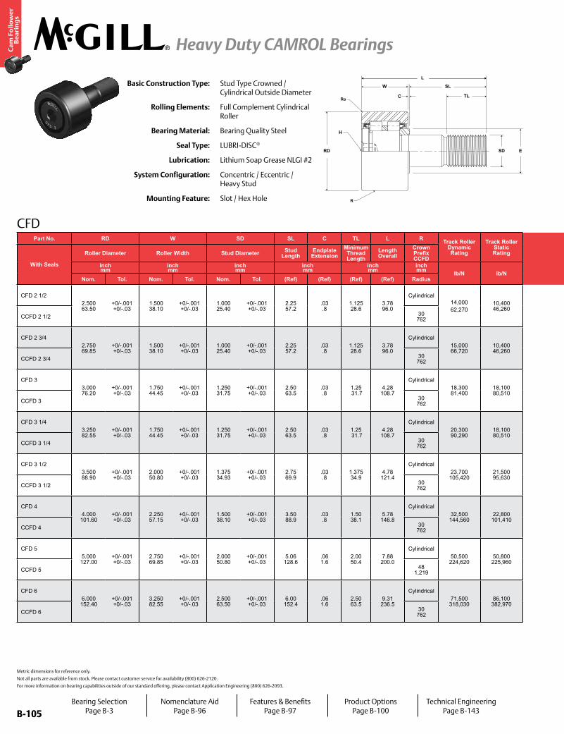
B-105
Ca
m F
oll
ow
er
Be
ari
ng
s
Heavy Duty CAMROL Bearings
B-105
Part No. RD W SD SL C TL L R Track Roller Dynamic Rating
Track Roller Static Rating
Part No. H E Ro Housing Bore
DiameterThread Type
Clamping TorqueWT
With Seals
Roller Diameter Roller Width Stud Diameter Stud Length
Endplate Extension
Minimum Thread Length
Length Overall
Crown Prefix CCFD
With Seals
Hex Hole Min. Clamping Diameter Corner Bearing Weight
inch mm
inch mm
inch mm
inch mm
inch mm
inch mm lb/N lb/N
inch mm
inch mm
inch mm in-lb
NmlbkgNom. Tol. Nom. Tol. Nom. Tol. (Ref) (Ref) (Ref) (Ref) Radius Size (Ref) (Ref) Nom. Tol.
CFD 2 1/22.500 63.50
+0/-.001 +0/-.03
1.500 38.10
+0/-.001 +0/-.03
1.000 25.40
+0/-.001 +0/-.03
2.25 57.2
.03 .8
1.125 28.6
3.78 96.0
Cylindrical14,00062,270
10,400 46,260
CFD 2 1/2.50
12.71.69 42.9
.09 2.4
1.0003 25.408
+.0002/-.0003 +.0005/-.0040 1-14 2,250
2542.38 1.08
CCFD 2 1/2 30 762 CCFD 2 1/2 N/A
CFD 2 3/42.750 69.85
+0/-.001 +0/-.03
1.500 38.10
+0/-.001 +0/-.03
1.000 25.40
+0/-.001 +0/-.03
2.25 57.2
.03 .8
1.125 28.6
3.78 96.0
Cylindrical15,000 66,720
10,400 46,260
CFD 2 3/4.50
12.71.69 42.9
.09 2.4
1.0003 25.408
+.0002/-.0003 +.0005/-.0044 1-14 2,250
2542.93 1.33
CCFD 2 3/4 30 762 CCFD 2 3/4 N/A
CFD 33.000 76.20
+0/-.001 +0/-.03
1.750 44.45
+0/-.001 +0/-.03
1.250 31.75
+0/-.001 +0/-.03
2.50 63.5
.03 .8
1.25 31.7
4.28 108.7
Cylindrical18,300 81,400
18,100 80,510
CFD 3.75
19.12.13 54.0
.13 3.2
1.2503 31.758
+.0002/-.0003 +.0005/-.0048 1 1/4-12 3,450
3904.20 1.91
CCFD 3 30 762 CCFD 3 N/A
CFD 3 1/43.250 82.55
+0/-.001 +0/-.03
1.750 44.45
+0/-.001 +0/-.03
1.250 31.75
+0/-.001 +0/-.03
2.50 63.5
.03 .8
1.25 31.7
4.28 108.7
Cylindrical20,300 90,290
18,100 80,510
CFD 3 1/4.75
19.12.13 54.0
.13 3.2
1.2503 31.758
+.0002/-.0003 +.0005/-.0052 1 1/4-12 3,450
3904.52 2.05
CCFD 3 1/4 30 762 CCFD 3 1/4 N/A
CFD 3 1/23.500 88.90
+0/-.001 +0/-.03
2.000 50.80
+0/-.001 +0/-.03
1.375 34.93
+0/-.001 +0/-.03
2.75 69.9
.03 .8
1.375 34.9
4.78 121.4
Cylindrical23,700 105,420
21,500 95,630
CFD 3 1/2.75
19.12.44 61.9
.13 3.2
1.3753 34.933
+.0002/-.0003 +.0005/-.0056 1 3/8-12 4,200
4755.99 2.72
CCFD 3 1/2 30 762 CCFD 3 1/2 N/A
CFD 44.000 101.60
+0/-.001 +0/-.03
2.250 57.15
+0/-.001 +0/-.03
1.500 38.10
+0/-.001 +0/-.03
3.50 88.9
.03 .8
1.50 38.1
5.78 146.8
Cylindrical32,500 144,560
22,800 101,410
CFD 4.75
19.12.80 71.0
.13 3.2
1.5003 38.108
+.0002/-.0003 +.0005/-.0060 1 1/2-12 5,000
5658.97 4.07
CCFD 4 30 762 CCFD 4 N/A
CFD 55.000 127.00
+0/-.001 +0/-.03
2.750 69.85
+0/-.001 +0/-.03
2.000 50.80
+0/-.001 +0/-.03
5.06 128.6
.06 1.6
2.00 50.4
7.88 200.0
Cylindrical50,500 224,620
50,800 225,960
CFD 5.875 22.2
3.56 90.5
.13 3.2
2.0003 50.808
+.0002/-.0003 +.0005/-.0064 2-12 5,000
56518.37 8.33
CCFD 5 48 1,219 CCFD 5 N/A
CFD 66.000 152.40
+0/-.001 +0/-.03
3.250 82.55
+0/-.001 +0/-.03
2.500 63.50
+0/-.001 +0/-.03
6.00 152.4
.06 1.6
2.50 63.5
9.31 236.5
Cylindrical71,500 318,030
86,100 382,970
CFD 61.00 25.4
4.47 113.5
.13 3.2
2.5003 63.508
+.0002/-.0003 +.0005/-.0068 2 1/2-12 5,000
56531.99 14.51
CCFD 6 30 762 CCFD 6 N/A
H
SD
C
W
RD
SL
TL
E
R
Ro
LBasic Construction Type: Stud Type Crowned /
Cylindrical Outside Diameter
Rolling Elements: Full Complement Cylindrical Roller
Bearing Material: Bearing Quality Steel
Seal Type: LUBRI-DISC®
Lubrication: Lithium Soap Grease NLGI #2
System Configuration: Concentric / Eccentric / Heavy Stud
Mounting Feature: Slot / Hex Hole
Metric dimensions for reference only.
Not all parts are available from stock. Please contact customer service for availability (800) 626-2120.
For more information on bearing capabilities outside of our standard offering, please contact Application Engineering (800) 626-2093.
CFD
Bearing SelectionPage B-3
Nomenclature AidPage B-96
Features & BenefitsPage B-97
Product OptionsPage B-100
Technical EngineeringPage B-143
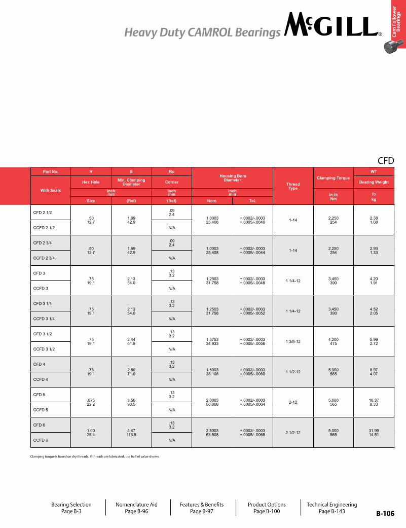
B-106
Ca
m F
oll
ow
er
Be
ari
ng
s
Heavy Duty CAMROL Bearings
B-106
Part No. RD W SD SL C TL L R Track Roller Dynamic Rating
Track Roller Static Rating
Part No. H E Ro Housing Bore
DiameterThread Type
Clamping TorqueWT
With Seals
Roller Diameter Roller Width Stud Diameter Stud Length
Endplate Extension
Minimum Thread Length
Length Overall
Crown Prefix CCFD
With Seals
Hex Hole Min. Clamping Diameter Corner Bearing Weight
inch mm
inch mm
inch mm
inch mm
inch mm
inch mm lb/N lb/N
inch mm
inch mm
inch mm in-lb
NmlbkgNom. Tol. Nom. Tol. Nom. Tol. (Ref) (Ref) (Ref) (Ref) Radius Size (Ref) (Ref) Nom. Tol.
CFD 2 1/22.500 63.50
+0/-.001 +0/-.03
1.500 38.10
+0/-.001 +0/-.03
1.000 25.40
+0/-.001 +0/-.03
2.25 57.2
.03 .8
1.125 28.6
3.78 96.0
Cylindrical14,00062,270
10,400 46,260
CFD 2 1/2.50 12.7
1.69 42.9
.09 2.4
1.0003 25.408
+.0002/-.0003 +.0005/-.0040 1-14 2,250
2542.38 1.08
CCFD 2 1/2 30 762 CCFD 2 1/2 N/A
CFD 2 3/42.750 69.85
+0/-.001 +0/-.03
1.500 38.10
+0/-.001 +0/-.03
1.000 25.40
+0/-.001 +0/-.03
2.25 57.2
.03 .8
1.125 28.6
3.78 96.0
Cylindrical15,000 66,720
10,400 46,260
CFD 2 3/4.50 12.7
1.69 42.9
.09 2.4
1.0003 25.408
+.0002/-.0003 +.0005/-.0044 1-14 2,250
2542.93 1.33
CCFD 2 3/4 30 762 CCFD 2 3/4 N/A
CFD 33.000 76.20
+0/-.001 +0/-.03
1.750 44.45
+0/-.001 +0/-.03
1.250 31.75
+0/-.001 +0/-.03
2.50 63.5
.03 .8
1.25 31.7
4.28 108.7
Cylindrical18,300 81,400
18,100 80,510
CFD 3.75 19.1
2.13 54.0
.13 3.2
1.2503 31.758
+.0002/-.0003 +.0005/-.0048 1 1/4-12 3,450
3904.20 1.91
CCFD 3 30 762 CCFD 3 N/A
CFD 3 1/43.250 82.55
+0/-.001 +0/-.03
1.750 44.45
+0/-.001 +0/-.03
1.250 31.75
+0/-.001 +0/-.03
2.50 63.5
.03 .8
1.25 31.7
4.28 108.7
Cylindrical20,300 90,290
18,100 80,510
CFD 3 1/4.75 19.1
2.13 54.0
.13 3.2
1.2503 31.758
+.0002/-.0003 +.0005/-.0052 1 1/4-12 3,450
3904.52 2.05
CCFD 3 1/4 30 762 CCFD 3 1/4 N/A
CFD 3 1/23.500 88.90
+0/-.001 +0/-.03
2.000 50.80
+0/-.001 +0/-.03
1.375 34.93
+0/-.001 +0/-.03
2.75 69.9
.03 .8
1.375 34.9
4.78 121.4
Cylindrical23,700 105,420
21,500 95,630
CFD 3 1/2.75 19.1
2.44 61.9
.13 3.2
1.3753 34.933
+.0002/-.0003 +.0005/-.0056 1 3/8-12 4,200
4755.99 2.72
CCFD 3 1/2 30 762 CCFD 3 1/2 N/A
CFD 44.000
101.60+0/-.001 +0/-.03
2.250 57.15
+0/-.001 +0/-.03
1.500 38.10
+0/-.001 +0/-.03
3.50 88.9
.03 .8
1.50 38.1
5.78 146.8
Cylindrical32,500 144,560
22,800 101,410
CFD 4.75 19.1
2.80 71.0
.13 3.2
1.5003 38.108
+.0002/-.0003 +.0005/-.0060 1 1/2-12 5,000
5658.97 4.07
CCFD 4 30 762 CCFD 4 N/A
CFD 55.000
127.00+0/-.001 +0/-.03
2.750 69.85
+0/-.001 +0/-.03
2.000 50.80
+0/-.001 +0/-.03
5.06 128.6
.06 1.6
2.00 50.4
7.88 200.0
Cylindrical50,500 224,620
50,800 225,960
CFD 5.875 22.2
3.56 90.5
.13 3.2
2.0003 50.808
+.0002/-.0003 +.0005/-.0064 2-12 5,000
56518.37 8.33
CCFD 5 48 1,219 CCFD 5 N/A
CFD 66.000
152.40+0/-.001 +0/-.03
3.250 82.55
+0/-.001 +0/-.03
2.500 63.50
+0/-.001 +0/-.03
6.00 152.4
.06 1.6
2.50 63.5
9.31 236.5
Cylindrical71,500 318,030
86,100 382,970
CFD 61.00 25.4
4.47 113.5
.13 3.2
2.5003 63.508
+.0002/-.0003 +.0005/-.0068 2 1/2-12 5,000
56531.99 14.51
CCFD 6 30 762 CCFD 6 N/A
CFD
Bearing SelectionPage B-3
Nomenclature AidPage B-96
Features & BenefitsPage B-97
Product OptionsPage B-100
Technical EngineeringPage B-143
Clamping torque is based on dry threads. If threads are lubricated, use half of value shown.
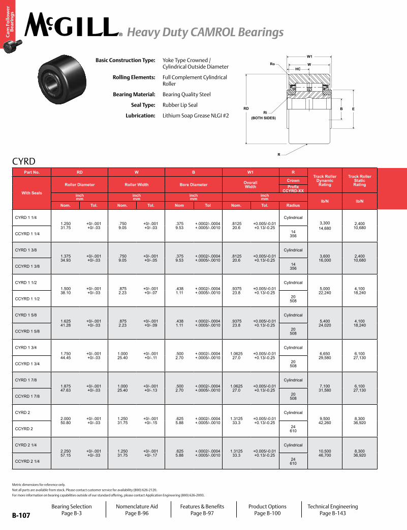
B-107
Ca
m F
oll
ow
er
Be
ari
ng
s
Heavy Duty CAMROL Bearings
B-107
CYRD
Ri(BOTH SIDES)
RD
W
B E
W1
R
RoHC
Basic Construction Type: Yoke Type Crowned / Cylindrical Outside Diameter
Rolling Elements: Full Complement Cylindrical Roller
Bearing Material: Bearing Quality Steel
Seal Type: Rubber Lip Seal
Lubrication: Lithium Soap Grease NLGI #2
Metric dimensions for reference only.
Not all parts are available from stock. Please contact customer service for availability (800) 626-2120.
For more information on bearing capabilities outside of our standard offering, please contact Application Engineering (800) 626-2093.
Part No. RD W B W1 RTrack Roller
Dynamic Rating
Track Roller Static Rating
Part No. HC E Ri Ro Recommended Shaft Diameters
WT
With Seals
Roller Diameter Roller Width Bore Diameter Overall Width
Crown
With Seals
Hole Center
Min. Clamping Diameter
Outer Corner Radius
Inner Corner Radius
Bearing WeightPrefix
CCYRD-XX Push Fit Drive Fit Press Fitinch mm
inch mm
inch mm
inch mm lb/N lb/N
inch mm
inch mm
inch mm
inch mm
inch mm lb
kgNom. Tol. Nom. Tol. Nom Tol Nom. Tol. Radius (Ref) (Ref) (Ref) (Ref) Nom Tol Nom Tol Nom Tol
CYRD 1 1/41.250 31.75
+0/-.001 +0/-.03
.750 9.05
+0/-.001 +0/-.03
.375 9.53
+.0002/-.0004 +.0005/-.0010
.8125 20.6
+0.005/-0.01 +0.13/-0.25
Cylindrical3,30014,680
2,400 10,680
CYRD 1 1/4.31 7.9
.98 5.0
.03 0.8
.03 0.8
.3745 9.512
±.0002 ±.005
.3751 9.53
±.0002 ±.005
.3753 9.53
±.0002 ±.005
.21
.09CCYRD 1 1/4 14
356 CCYRD 1 1/4
CYRD 1 3/81.375 34.93
+0/-.001 +0/-.03
.750 9.05
+0/-.001 +0/-.05
.375 9.53
+.0002/-.0004 +.0005/-.0010
.8125 20.6
+0.005/-0.01 +0.13/-0.25
Cylindrical3,600 16,000
2,400 10,680
CYRD 1 3/8.31 7.9
.98 5.0
.03 0.8
.05 1.2
.3745 9.512
±.0002 ±.005
.3751 9.53
±.0002 ±.005
.3753 9.53
±.0002 ±.005
.26
.12CCYRD 1 3/8 14
356 CCYRD 1 3/8
CYRD 1 1/21.500 38.10
+0/-.001 +0/-.03
.875 2.23
+0/-.001 +0/-.07
.438 1.11
+.0002/-.0004 +.0005/-.0010
.9375 23.8
+0.005/-0.01 +0.13/-0.25
Cylindrical5,000 22,240
4,100 18,240
CYRD 1 1/2.38 9.5
1.09 27.8
.04 1.0
.06 1.6
.4370 1.100
±.0002 ±.005
.4376 11.12
±.0002 ±.005
.4378 11.12
±.0002 ±.005
.35
.16CCYRD 1 1/2 20
508 CCYRD 1 1/2
CYRD 1 5/81.625 41.28
+0/-.001 +0/-.03
.875 2.23
+0/-.001 +0/-.09
.438 1.11
+.0002/-.0004 +.0005/-.0010
.9375 23.8
+0.005/-0.01 +0.13/-0.25
Cylindrical5,400 24,020
4,100 18,240
CYRD 1 5/8.38 9.5
1.09 27.8
.04 1.0
.06 1.6
.4370 1.100
±.0002 ±.005
.4376 11.12
±.0002 ±.005
.4378 11.12
±.0002 ±.005
.43
.19CCYRD 1 5/8 20
508 CCYRD 1 5/8
CYRD 1 3/41.750 44.45
+0/-.001 +0/-.03
1.000 25.40
+0/-.001 +0/-.11
.500 2.70
+.0002/-.0004 +.0005/-.0010
1.0625 27.0
+0.005/-0.01 +0.13/-0.25
Cylindrical6,650 29,580
6,100 27,130
CYRD 1 3/4.44 1.1
1.25 31.8
.05 1.3
.06 1.6
.4995 2.687
±.0002 ±.005
.5001 12.70
±.0002 ±.005
.5005 12.71
±.0002 ±.005
.57
.26CCYRD 1 3/4 20
508 CCYRD 1 3/4
CYRD 1 7/81.875 47.63
+0/-.001 +0/-.03
1.000 25.40
+0/-.001 +0/-.13
.500 2.70
+.0002/-.0004 +.0005/-.0010
1.0625 27.0
+0.005/-0.01 +0.13/-0.25
Cylindrical7,100 31,580
6,100 27,130
CYRD 1 7/8.44 1.1
1.25 31.8
.05 1.3
.06 1.6
.4995 2.687
±.0002 ±.005
.5001 12.70
±.0002 ±.005
.5005 12.71
±.0002 ±.005
.66
.29CCYRD 1 7/8 20
508 CCYRD 1 7/8
CYRD 22.000 50.80
+0/-.001 +0/-.03
1.250 31.75
+0/-.001 +0/-.15
.625 5.88
+.0002/-.0004 +.0005/-.0010
1.3125 33.3
+0.005/-0.01 +0.13/-0.25
Cylindrical9,500 42,260
8,300 36,920
CYRD 2.50 2.7
1.41 35.7
.06 1.5
.09 2.4
.6245 5.862
±.0002 ±.005
.6251 15.88
±.0002 ±.005
.6255 15.89
±.0002 ±.005
.88
.39CCYRD 2 24
610 CCYRD 2
CYRD 2 1/42.250 57.15
+0/-.001 +0/-.03
1.250 31.75
+0/-.001 +0/-.17
.625 5.88
+.0002/-.0004 +.0005/-.0010
1.3125 33.3
+0.005/-0.01 +0.13/-0.25
Cylindrical10,500 46,700
8,300 36,920
CYRD 2 1/4.50 2.7
1.41 35.7
.06 1.5
.09 2.4
.6245 5.862
±.0002 ±.005
.6251 15.88
±.0002 ±.005
.6255 15.89
±.0002 ±.005
1.18 .54
CCYRD 2 1/4 24 610 CCYRD 2 1/4
Bearing SelectionPage B-3
Nomenclature AidPage B-96
Features & BenefitsPage B-97
Product OptionsPage B-100
Technical EngineeringPage B-143

B-108
Ca
m F
oll
ow
er
Be
ari
ng
s
Heavy Duty CAMROL Bearings
B-108
CYRDPart No. RD W B W1 R
Track Roller Dynamic Rating
Track Roller Static Rating
Part No. HC E Ri Ro Recommended Shaft Diameters
WT
With Seals
Roller Diameter Roller Width Bore Diameter Overall Width
Crown
With Seals
Hole Center
Min. Clamping Diameter
Outer Corner Radius
Inner Corner Radius
Bearing WeightPrefix
CCYRD-XX Push Fit Drive Fit Press Fitinch mm
inch mm
inch mm
inch mm lb/N lb/N
inch mm
inch mm
inch mm
inch mm
inch mm lb
kgNom. Tol. Nom. Tol. Nom Tol Nom. Tol. Radius (Ref) (Ref) (Ref) (Ref) Nom Tol Nom Tol Nom Tol
CYRD 1 1/41.250 31.75
+0/-.001 +0/-.03
.750 9.05
+0/-.001 +0/-.03
.375 9.53
+.0002/-.0004 +.0005/-.0010
.8125 20.6
+0.005/-0.01 +0.13/-0.25
Cylindrical3,30014,680
2,400 10,680
CYRD 1 1/4.31 7.9
.98 5.0
.03 0.8
.03 0.8
.3745 9.512
±.0002 ±.005
.3751 9.53
±.0002 ±.005
.3753 9.53
±.0002 ±.005
.21
.09CCYRD 1 1/4 14
356 CCYRD 1 1/4
CYRD 1 3/81.375 34.93
+0/-.001 +0/-.03
.750 9.05
+0/-.001 +0/-.05
.375 9.53
+.0002/-.0004 +.0005/-.0010
.8125 20.6
+0.005/-0.01 +0.13/-0.25
Cylindrical3,600 16,000
2,400 10,680
CYRD 1 3/8.31 7.9
.98 5.0
.03 0.8
.05 1.2
.3745 9.512
±.0002 ±.005
.3751 9.53
±.0002 ±.005
.3753 9.53
±.0002 ±.005
.26
.12CCYRD 1 3/8 14
356 CCYRD 1 3/8
CYRD 1 1/21.500 38.10
+0/-.001 +0/-.03
.875 2.23
+0/-.001 +0/-.07
.438 1.11
+.0002/-.0004 +.0005/-.0010
.9375 23.8
+0.005/-0.01 +0.13/-0.25
Cylindrical5,000 22,240
4,100 18,240
CYRD 1 1/2.38 9.5
1.09 27.8
.04 1.0
.06 1.6
.4370 1.100
±.0002 ±.005
.4376 11.12
±.0002 ±.005
.4378 11.12
±.0002 ±.005
.35
.16CCYRD 1 1/2 20
508 CCYRD 1 1/2
CYRD 1 5/81.625 41.28
+0/-.001 +0/-.03
.875 2.23
+0/-.001 +0/-.09
.438 1.11
+.0002/-.0004 +.0005/-.0010
.9375 23.8
+0.005/-0.01 +0.13/-0.25
Cylindrical5,400 24,020
4,100 18,240
CYRD 1 5/8.38 9.5
1.09 27.8
.04 1.0
.06 1.6
.4370 1.100
±.0002 ±.005
.4376 11.12
±.0002 ±.005
.4378 11.12
±.0002 ±.005
.43
.19CCYRD 1 5/8 20
508 CCYRD 1 5/8
CYRD 1 3/41.750 44.45
+0/-.001 +0/-.03
1.000 25.40
+0/-.001 +0/-.11
.500 2.70
+.0002/-.0004 +.0005/-.0010
1.0625 27.0
+0.005/-0.01 +0.13/-0.25
Cylindrical6,650 29,580
6,100 27,130
CYRD 1 3/4.44 1.1
1.25 31.8
.05 1.3
.06 1.6
.4995 2.687
±.0002 ±.005
.5001 12.70
±.0002 ±.005
.5005 12.71
±.0002 ±.005
.57
.26CCYRD 1 3/4 20
508 CCYRD 1 3/4
CYRD 1 7/81.875 47.63
+0/-.001 +0/-.03
1.000 25.40
+0/-.001 +0/-.13
.500 2.70
+.0002/-.0004 +.0005/-.0010
1.0625 27.0
+0.005/-0.01 +0.13/-0.25
Cylindrical7,100 31,580
6,100 27,130
CYRD 1 7/8.44 1.1
1.25 31.8
.05 1.3
.06 1.6
.4995 2.687
±.0002 ±.005
.5001 12.70
±.0002 ±.005
.5005 12.71
±.0002 ±.005
.66
.29CCYRD 1 7/8 20
508 CCYRD 1 7/8
CYRD 22.000 50.80
+0/-.001 +0/-.03
1.250 31.75
+0/-.001 +0/-.15
.625 5.88
+.0002/-.0004 +.0005/-.0010
1.3125 33.3
+0.005/-0.01 +0.13/-0.25
Cylindrical9,500 42,260
8,300 36,920
CYRD 2.50 2.7
1.41 35.7
.06 1.5
.09 2.4
.6245 5.862
±.0002 ±.005
.6251 15.88
±.0002 ±.005
.6255 15.89
±.0002 ±.005
.88
.39CCYRD 2 24
610 CCYRD 2
CYRD 2 1/42.250 57.15
+0/-.001 +0/-.03
1.250 31.75
+0/-.001 +0/-.17
.625 5.88
+.0002/-.0004 +.0005/-.0010
1.3125 33.3
+0.005/-0.01 +0.13/-0.25
Cylindrical10,500 46,700
8,300 36,920
CYRD 2 1/4.50 2.7
1.41 35.7
.06 1.5
.09 2.4
.6245 5.862
±.0002 ±.005
.6251 15.88
±.0002 ±.005
.6255 15.89
±.0002 ±.005
1.18 .54
CCYRD 2 1/4 24 610 CCYRD 2 1/4
Bearing SelectionPage B-3
Nomenclature AidPage B-96
Features & BenefitsPage B-97
Product OptionsPage B-100
Technical EngineeringPage B-143

B-109
Ca
m F
oll
ow
er
Be
ari
ng
s
Heavy Duty CAMROL Bearings
B-109
CYRD
Metric dimensions for reference only.
Not all parts are available from stock. Please contact customer service for availability (800) 626-2120.
For more information on bearing capabilities outside of our standard offering, please contact Application Engineering (800) 626-2093.
Part No. RD W B W1 RTrack Roller
Dynamic Rating
Track Roller Static Rating
Part No. HC E Ri Ro Recommended Shaft Diameters
WT
With Seals
Roller Diameter Roller Width Bore Diameter Overall Width
Crown
With Seals
Hole Center
Min. Clamping Diameter
Outer Corner Radius
Inner Corner Radius
Bearing WeightPrefix
CCYRD-XX Push Fit Drive Fit Press Fitinch mm
inch mm
inch mm
inch mm lb/N lb/N
inch mm
inch mm
inch mm
inch mm
inch mm lb
kgNom. Tol. Nom. Tol. Nom Tol Nom. Tol. Radius (Ref) (Ref) (Ref) (Ref) Nom Tol Nom Tol Nom Tol
CYRD 2 1/22.500 63.50
+0/-.001 +0/-.03
1.500 38.10
+0/-.001 +0/-.19
.750 9.05
+.0002/-.0004 +.0005/-.0010
1.5625 39.7
+0.005/-0.01 +0.13/-0.25
Cylindrical14,000 62,270
10,400 46,260
CYRD 2 1/2.56 4.3
1.69 42.9
.07 1.8
.09 2.4
.7495 9.037
±.0002 ±.005
.7501 19.05
±.0002 ±.005
.7505 19.06
±.0002 ±.005
1.74 .79
CCYRD 2 1/2 30 762 CCYRD 2 1/2
CYRD 2 3/42.750 69.85
+0/-.001 +0/-.03
1.500 38.10
+0/-.001 +0/-.21
.750 9.05
+.0002/-.0004 +.0005/-.0010
1.5625 39.7
+0.005/-0.01 +0.13/-0.25
Cylindrical15,000 66,720
10,400 46,260
CYRD 2 3/4.56 4.3
1.69 42.9
.07 1.8
.09 2.4
.7495 9.037
±.0002 ±.005
.7501 19.05
±.0002 ±.005
.7505 19.06
±.0002 ±.005
2.17 .98
CCYRD 2 3/4 30 762 CCYRD 2 3/4
CYRD 33.000 76.20
+0/-.001 +0/-.03
1.750 44.45
+0/-.001 +0/-.23
1.000 25.40
+.0001/-.0005 +.0003/-.0013
1.8125 46.0
+0.005/-0.01 +0.13/-0.25
Cylindrical18,300 81,400
18,100 80,510
CYRD 3.63 5.9
2.13 54.0
.08 2.0
.13 3.2
.9994 5.385
±.0002 ±.005
1.002 25.5
±.0002 ±.005
1.006 25.55
±.0002 ±.005
3.08 1.39
CCYRD 3 30 762 CCYRD 3
CYRD 3 1/43.250 82.55
+0/-.001 +0/-.03
1.750 44.45
+0/-.001 +0/-.25
1.000 25.40
+.0001/-.0005 +.0003/-.0013
1.8125 46.0
+0.005/-0.01 +0.13/-0.25
Cylindrical20,300 90,290
18,100 80,510
CYRD 3 1/4.63 5.9
2.13 54.0
.08 2.0
.13 3.2
.9994 5.385
±.0002 ±.005
1.002 25.5
±.0002 ±.005
1.006 25.55
±.0002 ±.005
3.62 1.64
CCYRD 3 1/4 30 762 CCYRD 3 1/4
CYRD 3 1/23.500 88.90
+0/-.001 +0/-.03
2.000 50.80
+0/-.001 +0/-.27
1.125 28.58
+.0001/-.0005 +.0003/-.0013
2.0625 52.4
+0.005/-0.01 +0.13/-0.25
Cylindrical23,700 105,420
21,500 95,630
CYRD 3 1/2.69 7.5
2.44 61.9
.09 2.3
.13 3.2
1.1244 28.560
±.0002 ±.005
1.1252 28.58
±.0002 ±.005
1.1256 28.59
±.0002 ±.005
4.41 2.00
CCYRD 3 1/2 30 762 CCYRD 3 1/2
CYRD 44.000 101.60
+0/-.001 +0/-.03
2.250 57.15
+0/-.001 +0/-.29
1.250 31.75
+.0001/-.0005 +.0003/-.0013
2.3125 58.7
+0.005/-0.01 +0.13/-0.25
Cylindrical32,500 144,560
22,800 101,410
CYRD 4.75 9.1
2.80 71.0
.10 2.5
.13 3.2
1.2494 31.735
±.0002 ±.005
1.2502 31.76
±.0002 ±.005
1.2506 31.77
±.0002 ±.005
6.57 2.98
CCYRD 4 30 762 CCYRD 4
CYRD 55.000 127.00
+0/-.001 +0/-.03
2.750 69.85
+0/-.001 +0/-.31
1.750 44.45
+.0001/-.0005 +.0003/-.0013
2.875 73.0
+0.005/-0.01 +0.13/-0.25
Cylindrical50,500 224,620
50,800 225,960
CYRD 5.88 2.2
3.56 90.5
.11 2.8
.13 3.2
1.7494 44.435
±.0002 ±.005
1.7502 44.46
±.0002 ±.005
1.7506 44.47
±.0002 ±.005
12.33 5.59
CCYRD 5 48 1,219 CCYRD 5
CYRD 66.000 152.40
+0/-.001 +0/-.03
3.250 82.55
+0/-.001 +0/-.33
2.250 57.15
+.0001/-.0005 +.0003/-.0013
3.375 85.7
+0.005/-0.01 +0.13/-0.25
Cylindrical71,500 318,030
86,100 382,970
CYRD 61.00 25.4
4.47 113.5
.12 3.0
.13 3.2
2.2494 57.135
±.0002 ±.005
2.2502 57.16
±.0002 ±.005
2.2506 57.17
±.0002 ±.005
20.47 9.29
CCYRD 6 56 1,422 CCYRD 6
Ri(BOTH SIDES)
RD
W
B E
W1
R
RoHC
Basic Construction Type: Yoke Type Crowned / Cylindrical Outside Diameter
Rolling Elements: Full Complement Cylindrical Roller
Bearing Material: Bearing Quality Steel
Seal Type: Rubber Lip Seal
Lubrication: Lithium Soap Grease NLGI #2
Bearing SelectionPage B-3
Nomenclature AidPage B-96
Features & BenefitsPage B-97
Product OptionsPage B-100
Technical EngineeringPage B-143
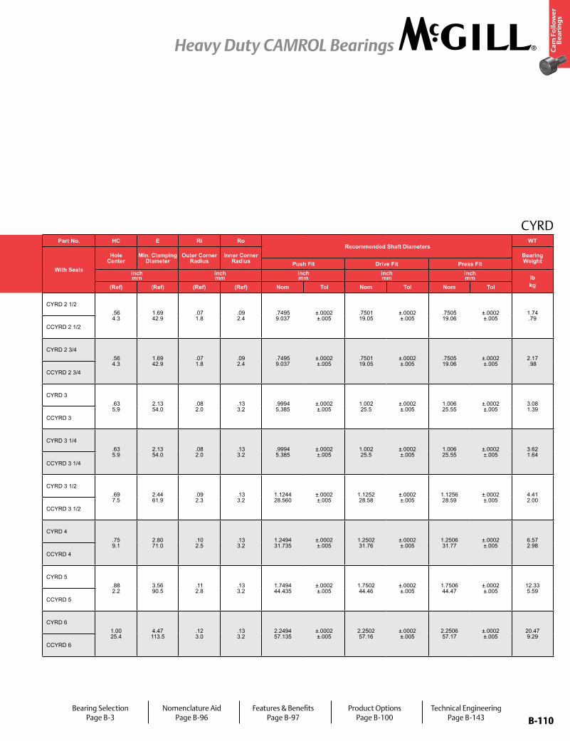
B-110
Ca
m F
oll
ow
er
Be
ari
ng
s
Heavy Duty CAMROL Bearings
B-110
CYRDPart No. RD W B W1 R
Track Roller Dynamic Rating
Track Roller Static Rating
Part No. HC E Ri Ro Recommended Shaft Diameters
WT
With Seals
Roller Diameter Roller Width Bore Diameter Overall Width
Crown
With Seals
Hole Center
Min. Clamping Diameter
Outer Corner Radius
Inner Corner Radius
Bearing WeightPrefix
CCYRD-XX Push Fit Drive Fit Press Fitinch mm
inch mm
inch mm
inch mm lb/N lb/N
inch mm
inch mm
inch mm
inch mm
inch mm lb
kgNom. Tol. Nom. Tol. Nom Tol Nom. Tol. Radius (Ref) (Ref) (Ref) (Ref) Nom Tol Nom Tol Nom Tol
CYRD 2 1/22.500 63.50
+0/-.001 +0/-.03
1.500 38.10
+0/-.001 +0/-.19
.750 9.05
+.0002/-.0004 +.0005/-.0010
1.5625 39.7
+0.005/-0.01 +0.13/-0.25
Cylindrical14,000 62,270
10,400 46,260
CYRD 2 1/2.56 4.3
1.69 42.9
.07 1.8
.09 2.4
.7495 9.037
±.0002 ±.005
.7501 19.05
±.0002 ±.005
.7505 19.06
±.0002 ±.005
1.74 .79
CCYRD 2 1/2 30 762 CCYRD 2 1/2
CYRD 2 3/42.750 69.85
+0/-.001 +0/-.03
1.500 38.10
+0/-.001 +0/-.21
.750 9.05
+.0002/-.0004 +.0005/-.0010
1.5625 39.7
+0.005/-0.01 +0.13/-0.25
Cylindrical15,000 66,720
10,400 46,260
CYRD 2 3/4.56 4.3
1.69 42.9
.07 1.8
.09 2.4
.7495 9.037
±.0002 ±.005
.7501 19.05
±.0002 ±.005
.7505 19.06
±.0002 ±.005
2.17 .98
CCYRD 2 3/4 30 762 CCYRD 2 3/4
CYRD 33.000 76.20
+0/-.001 +0/-.03
1.750 44.45
+0/-.001 +0/-.23
1.000 25.40
+.0001/-.0005 +.0003/-.0013
1.8125 46.0
+0.005/-0.01 +0.13/-0.25
Cylindrical18,300 81,400
18,100 80,510
CYRD 3.63 5.9
2.13 54.0
.08 2.0
.13 3.2
.9994 5.385
±.0002 ±.005
1.002 25.5
±.0002 ±.005
1.006 25.55
±.0002 ±.005
3.08 1.39
CCYRD 3 30 762 CCYRD 3
CYRD 3 1/43.250 82.55
+0/-.001 +0/-.03
1.750 44.45
+0/-.001 +0/-.25
1.000 25.40
+.0001/-.0005 +.0003/-.0013
1.8125 46.0
+0.005/-0.01 +0.13/-0.25
Cylindrical20,300 90,290
18,100 80,510
CYRD 3 1/4.63 5.9
2.13 54.0
.08 2.0
.13 3.2
.9994 5.385
±.0002 ±.005
1.002 25.5
±.0002 ±.005
1.006 25.55
±.0002 ±.005
3.62 1.64
CCYRD 3 1/4 30 762 CCYRD 3 1/4
CYRD 3 1/23.500 88.90
+0/-.001 +0/-.03
2.000 50.80
+0/-.001 +0/-.27
1.125 28.58
+.0001/-.0005 +.0003/-.0013
2.0625 52.4
+0.005/-0.01 +0.13/-0.25
Cylindrical23,700 105,420
21,500 95,630
CYRD 3 1/2.69 7.5
2.44 61.9
.09 2.3
.13 3.2
1.1244 28.560
±.0002 ±.005
1.1252 28.58
±.0002 ±.005
1.1256 28.59
±.0002 ±.005
4.41 2.00
CCYRD 3 1/2 30 762 CCYRD 3 1/2
CYRD 44.000
101.60+0/-.001 +0/-.03
2.250 57.15
+0/-.001 +0/-.29
1.250 31.75
+.0001/-.0005 +.0003/-.0013
2.3125 58.7
+0.005/-0.01 +0.13/-0.25
Cylindrical32,500 144,560
22,800 101,410
CYRD 4.75 9.1
2.80 71.0
.10 2.5
.13 3.2
1.2494 31.735
±.0002 ±.005
1.2502 31.76
±.0002 ±.005
1.2506 31.77
±.0002 ±.005
6.57 2.98
CCYRD 4 30 762 CCYRD 4
CYRD 55.000
127.00+0/-.001 +0/-.03
2.750 69.85
+0/-.001 +0/-.31
1.750 44.45
+.0001/-.0005 +.0003/-.0013
2.875 73.0
+0.005/-0.01 +0.13/-0.25
Cylindrical50,500 224,620
50,800 225,960
CYRD 5.88 2.2
3.56 90.5
.11 2.8
.13 3.2
1.7494 44.435
±.0002 ±.005
1.7502 44.46
±.0002 ±.005
1.7506 44.47
±.0002 ±.005
12.33 5.59
CCYRD 5 48 1,219 CCYRD 5
CYRD 66.000
152.40+0/-.001 +0/-.03
3.250 82.55
+0/-.001 +0/-.33
2.250 57.15
+.0001/-.0005 +.0003/-.0013
3.375 85.7
+0.005/-0.01 +0.13/-0.25
Cylindrical71,500 318,030
86,100 382,970
CYRD 61.00 25.4
4.47 113.5
.12 3.0
.13 3.2
2.2494 57.135
±.0002 ±.005
2.2502 57.16
±.0002 ±.005
2.2506 57.17
±.0002 ±.005
20.47 9.29
CCYRD 6 56 1,422 CCYRD 6
Bearing SelectionPage B-3
Nomenclature AidPage B-96
Features & BenefitsPage B-97
Product OptionsPage B-100
Technical EngineeringPage B-143
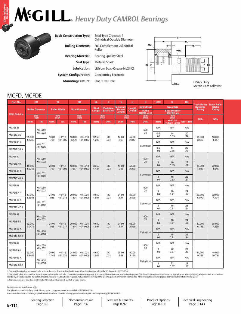
B-111
Ca
m F
oll
ow
er
Be
ari
ng
s
Heavy Duty CAMROL Bearings
B-111
Part No. RD W SD SL C TL L R ECC G BDTrack Roller
Dynamic Rating
Track Roller Static Rating
Part No. HC HD D E Ro HBD sdt Thread Type CT LSD WT
With Shields
Roller Diameter Roller Width Stud Diameter Stud Length
Endplate Extension
Minimum Thread Length
Length Overall
Cylindrical Eccentric
With Shields
Hole Center
Radial Lub. Hole
DiameterLub. Hole Dia. / Lub. Fitting
Min. Clamping Diameter
Outer Radius (suffix X)
Housing Bore Diameter
Thread Type
Clamping Torque
Limiting Speed
(Grease)Bearing WeightSuffix
MCFD-xx-XBase Modifier
MCFDE-xxmm inch
mm inch
mm inch
mm inch
mm inch
mm inch
mm inch N/lb N/lb
mm inch
mm inch
mm inch Nm
in-lb RPM kglbNom. Tol. Nom. Tol. Nom. Tol. (Ref) (Ref) (Ref) (Ref) (Ref) (Ref) +05/-.15
(+.002 / -.006) See Table (Ref) (Ref) (Ref) (Ref) (Ref) Nom. Tol.
MCFD 35
35.000 1.3780
+0/-.050 +0/-.002
18.00 .709
+0/.12 +0/-.005
16.000 .6299
+0/-.018 +0/-.0007
32.50 1.280
.80 .031
17.00 .669
52.00 2.047
500 20
N/A N/A N/A
16,000 3,597
18,000 4,047
MCFD 35
8.00 .315
3.00 .118
6.00 .236
21.00 .827
1.00 .039
16.000 .6299
+0/-.018 +0/-.0007 M16x1.5 85
752 6,500 .16 .36
MCFDE 35 0.5 .02
14 0.55
20 .79 MCFDE 35
MCFD 35 X+0/-.011
+0/-.0004 CylindricalN/A N/A N/A MCFD 35 X
MCFDE 35 X 0.5 .02
14 0.55
20 .79 MCFDE 35 X
MCFD 40
40.000 1.5748
+0/-.050 +0/-.002
20.00 .787
+0/.12 +0/-.009
18.000 .7087
+0/-.018 +0/-.0007
36.50 1.437
.80 .031
19.00 .748
58.00 2.283
500 20
N/A N/A N/A
18,000 4,047
22,000 4,946
MCFD 40
8.00 .315
3.00 .118
6.00 .236
23.00 .906
1.50 .059
18.000 .7087
+0/-.018 +0/-.0007 M18x1.5 85
752 5,500 .24 .53
MCFDE 40 1 .04
16 0.63
22 .87 MCFDE 40
MCFD 40 X+0/-.011
+0/-.0004 CylindricalN/A N/A N/A MCFD 40 X
MCFDE 40 X 1 .04
16 0.63
22 .87 MCFDE 40 X
MCFD 47
47.000 1.8504
+0/-.050 +0/-.002
24.00 .945
+0/.12 +0/-.013
20.000 .7874
+0/-.021 +0/-.0008
40.50 1.594
.80 .031
21.00 .827
66.00 2.598
500 20
N/A N/A N/A
27,000 6,070
32,000 7,194
MCFD 47
9.00 .354
4.00 .157
8.00 .315
27.00 1.063
1.50 .059
20.000 .7874
+0/-.021 +0/-.0008 M20x1.5 118
1,044 4,200 .38 .84
MCFDE 47 1 .04
18 0.71
24 .94 MCFDE 47
MCFD 47 X+0/-.011
+0/-.0004 CylindricalN/A N/A N/A MCFD 47 X
MCFDE 47 X 1 .04
18 0.71
24 .94 MCFDE 47 X
MCFD 52
52.000 2.0472
+0/-.050 +0/-.002
24.00 .945
+0/.12 +0/-.017
20.000 .7874
+0/-.021 +0/-.0008
40.50 1.594
.80 .031
21.00 .827
66.00 2.598
500 20
N/A N/A N/A
30,000 6,745
35,000 7,869
MCFD 52
9.00 .354
4.00 .157
8.00 .315
21.00 .827
1.50 .059
20.000 .7874
+0/-.021 +0/-.0008 M20x1.5 118
1,044 3,400 .45 .99
MCFDE 52 1 .04
18 0.71
24 .94 MCFDE 52
MCFD 52 X+0/-.013 +0/-.0005 Cylindrical
N/A N/A N/A MCFD 52 X
MCFDE 52 X 1 .04
18 0.71
24 .94 MCFDE 52 X
MCFD 62
62.000 2.4409
+0/-.050 +0/-.002
29.00 1.142
+0/.12 +0/-.021
24.000 .9449
+0/-.021 +0/-.0008
49.50 1.949
.80 .031
25.00 .984
80.00 3.150
500 20
N/A N/A N/A
41,000 9,218
48,000 10,791
MCFD 62
11.00 .433
4.00 .157
8.00 .315
38.00 1.496
2.00 .079
24.000 .9449
+0/-.021 +0/-.0008 M24x1.5 216
1,912 2,600.801.75
MCFDE 62 1 .04
22 0.87
28 .10 MCFDE 62
MCFD 62 X+0/-.013 +0/-.0005 Cylindrical
N/A N/A N/A MCFD 62 X
MCFDE 62 X 1 .04
22 0.87
28 .10 MCFDE 62 X
MCFD, MCFDE
Basic Construction Type: Stud Type Crowned / Cylindrical Outside Diameter
Rolling Elements: Full Complement Cylindrical Roller
Bearing Material: Bearing Quality Steel
Seal Type: Metallic Shield
Lubrication: Lithium Soap Grease NLGI #2
System Configuration: Concentric / Eccentric
Mounting Feature: Slot / Hex Hole
Inch dimensions for reference only.
Not all parts are available from stock. Please contact customer service for availability (800) 626-2120.
For more information on bearing capabilities outside of our standard offering, please contact Application Engineering (800) 626-2093.
1. Standard bearing has a crowned roller outside diameter. For straight cylindrical outside roller diameter, add suffix “X”. Example - MCFD-35-X.
2. Since load, lubrication method, temperature and other factors affect the maximum operating speed, it is impossible to determine precise limiting speed. The listed limiting speeds are based on lightly loaded bearings having adequate lubrication and are listed only as a design guide. If grease lubricated, frequent relubrication is required. Actual bearing testing in the specific application should be conducted if the anticipated operating speed approaches the listed limiting speed.
3. Clamping torque is based on dry threads. If threads are lubricated, use half of value shown.
Heavy Duty Metric Cam Follower
Bearing SelectionPage B-3
Nomenclature AidPage B-96
Features & BenefitsPage B-97
Product OptionsPage B-100
Technical EngineeringPage B-143
FRD
C
W
F SD E
L
SL
TL
HD
HC
Ro
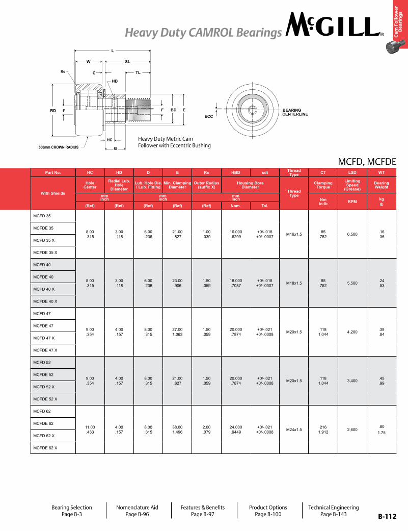
B-112
Ca
m F
oll
ow
er
Be
ari
ng
s
Heavy Duty CAMROL Bearings
B-112
Part No. RD W SD SL C TL L R ECC G BDTrack Roller
Dynamic Rating
Track Roller Static Rating
Part No. HC HD D E Ro HBD sdt Thread Type CT LSD WT
With Shields
Roller Diameter Roller Width Stud Diameter Stud Length
Endplate Extension
Minimum Thread Length
Length Overall
Cylindrical Eccentric
With Shields
Hole Center
Radial Lub. Hole
DiameterLub. Hole Dia. / Lub. Fitting
Min. Clamping Diameter
Outer Radius (suffix X)
Housing Bore Diameter
Thread Type
Clamping Torque
Limiting Speed
(Grease)Bearing WeightSuffix
MCFD-xx-XBase Modifier
MCFDE-xxmm inch
mm inch
mm inch
mm inch
mm inch
mm inch
mm inch N/lb N/lb
mm inch
mm inch
mm inch Nm
in-lb RPM kglbNom. Tol. Nom. Tol. Nom. Tol. (Ref) (Ref) (Ref) (Ref) (Ref) (Ref) +05/-.15
(+.002 / -.006) See Table (Ref) (Ref) (Ref) (Ref) (Ref) Nom. Tol.
MCFD 35
35.000 1.3780
+0/-.050 +0/-.002
18.00 .709
+0/.12 +0/-.005
16.000 .6299
+0/-.018 +0/-.0007
32.50 1.280
.80 .031
17.00 .669
52.00 2.047
500 20
N/A N/A N/A
16,000 3,597
18,000 4,047
MCFD 35
8.00 .315
3.00 .118
6.00 .236
21.00 .827
1.00 .039
16.000 .6299
+0/-.018 +0/-.0007 M16x1.5 85
752 6,500 .16 .36
MCFDE 35 0.5 .02
14 0.55
20 .79 MCFDE 35
MCFD 35 X+0/-.011
+0/-.0004 CylindricalN/A N/A N/A MCFD 35 X
MCFDE 35 X 0.5 .02
14 0.55
20 .79 MCFDE 35 X
MCFD 40
40.000 1.5748
+0/-.050 +0/-.002
20.00 .787
+0/.12 +0/-.009
18.000 .7087
+0/-.018 +0/-.0007
36.50 1.437
.80 .031
19.00 .748
58.00 2.283
500 20
N/A N/A N/A
18,000 4,047
22,000 4,946
MCFD 40
8.00 .315
3.00 .118
6.00 .236
23.00 .906
1.50 .059
18.000 .7087
+0/-.018 +0/-.0007 M18x1.5 85
752 5,500 .24 .53
MCFDE 40 1 .04
16 0.63
22 .87 MCFDE 40
MCFD 40 X+0/-.011
+0/-.0004 CylindricalN/A N/A N/A MCFD 40 X
MCFDE 40 X 1 .04
16 0.63
22 .87 MCFDE 40 X
MCFD 47
47.000 1.8504
+0/-.050 +0/-.002
24.00 .945
+0/.12 +0/-.013
20.000 .7874
+0/-.021 +0/-.0008
40.50 1.594
.80 .031
21.00 .827
66.00 2.598
500 20
N/A N/A N/A
27,000 6,070
32,000 7,194
MCFD 47
9.00 .354
4.00 .157
8.00 .315
27.00 1.063
1.50 .059
20.000 .7874
+0/-.021 +0/-.0008 M20x1.5 118
1,044 4,200 .38 .84
MCFDE 47 1 .04
18 0.71
24 .94 MCFDE 47
MCFD 47 X+0/-.011
+0/-.0004 CylindricalN/A N/A N/A MCFD 47 X
MCFDE 47 X 1 .04
18 0.71
24 .94 MCFDE 47 X
MCFD 52
52.000 2.0472
+0/-.050 +0/-.002
24.00 .945
+0/.12 +0/-.017
20.000 .7874
+0/-.021 +0/-.0008
40.50 1.594
.80 .031
21.00 .827
66.00 2.598
500 20
N/A N/A N/A
30,000 6,745
35,000 7,869
MCFD 52
9.00 .354
4.00 .157
8.00 .315
21.00 .827
1.50 .059
20.000 .7874
+0/-.021 +0/-.0008 M20x1.5 118
1,044 3,400 .45 .99
MCFDE 52 1 .04
18 0.71
24 .94 MCFDE 52
MCFD 52 X+0/-.013
+0/-.0005 CylindricalN/A N/A N/A MCFD 52 X
MCFDE 52 X 1 .04
18 0.71
24 .94 MCFDE 52 X
MCFD 62
62.000 2.4409
+0/-.050 +0/-.002
29.00 1.142
+0/.12 +0/-.021
24.000 .9449
+0/-.021 +0/-.0008
49.50 1.949
.80 .031
25.00 .984
80.00 3.150
500 20
N/A N/A N/A
41,000 9,218
48,000 10,791
MCFD 62
11.00 .433
4.00 .157
8.00 .315
38.00 1.496
2.00 .079
24.000 .9449
+0/-.021 +0/-.0008 M24x1.5 216
1,912 2,600.80
1.75
MCFDE 62 1 .04
22 0.87
28 .10 MCFDE 62
MCFD 62 X+0/-.013
+0/-.0005 CylindricalN/A N/A N/A MCFD 62 X
MCFDE 62 X 1 .04
22 0.87
28 .10 MCFDE 62 X
MCFD, MCFDE
HC
Ro
BEARING CENTERLINE
FRD F BD E
G
C
W SL
TL
L
HD
ECC
500mm CROWN RADIUS
Heavy Duty Metric Cam Follower with Eccentric Bushing
Bearing SelectionPage B-3
Nomenclature AidPage B-96
Features & BenefitsPage B-97
Product OptionsPage B-100
Technical EngineeringPage B-143
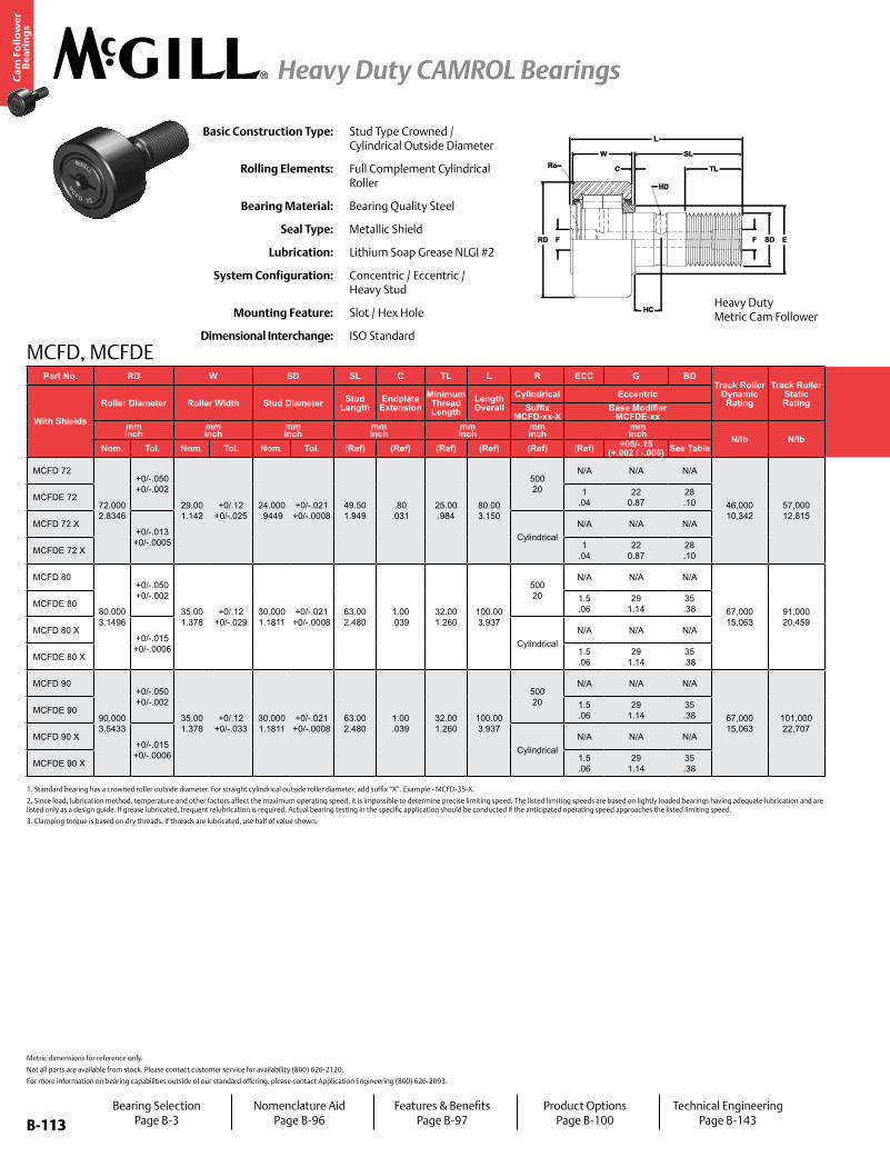
B-113
Ca
m F
oll
ow
er
Be
ari
ng
s
Heavy Duty CAMROL Bearings
B-113
MCFD, MCFDE
Basic Construction Type: Stud Type Crowned / Cylindrical Outside Diameter
Rolling Elements: Full Complement Cylindrical Roller
Bearing Material: Bearing Quality Steel
Seal Type: Metallic Shield
Lubrication: Lithium Soap Grease NLGI #2
System Configuration: Concentric / Eccentric / Heavy Stud
Mounting Feature: Slot / Hex Hole
Dimensional Interchange: ISO Standard
Metric dimensions for reference only.
Not all parts are available from stock. Please contact customer service for availability (800) 626-2120.
For more information on bearing capabilities outside of our standard offering, please contact Application Engineering (800) 626-2093.
1. Standard bearing has a crowned roller outside diameter. For straight cylindrical outside roller diameter, add suffix “X”. Example - MCFD-35-X.
2. Since load, lubrication method, temperature and other factors affect the maximum operating speed, it is impossible to determine precise limiting speed. The listed limiting speeds are based on lightly loaded bearings having adequate lubrication and are listed only as a design guide. If grease lubricated, frequent relubrication is required. Actual bearing testing in the specific application should be conducted if the anticipated operating speed approaches the listed limiting speed.
3. Clamping torque is based on dry threads. If threads are lubricated, use half of value shown.
Part No. RD W SD SL C TL L R ECC G BDTrack Roller
Dynamic Rating
Track Roller Static Rating
Part No. HC HD D E Ro HBD sdt Thread Type CT LSD WT
With Shields
Roller Diameter Roller Width Stud Diameter Stud Length
Endplate Extension
Minimum Thread Length
Length Overall
Cylindrical Eccentric
With Shields
Hole Center
Radial Lub. Hole
DiameterLub. Hole Dia. / Lub. Fitting
Min. Clamping Diameter
Outer Radius (suffix X)
Housing Bore Diameter
Thread Type
Clamping Torque
Limiting Speed
(Grease)Bearing WeightSuffix
MCFD-xx-XBase Modifier
MCFDE-xxmm inch
mm inch
mm inch
mm inch
mm inch
mm inch
mm inch N/lb N/lb
mm inch
mm inch
mm inch Nm
in-lb RPM kglbNom. Tol. Nom. Tol. Nom. Tol. (Ref) (Ref) (Ref) (Ref) (Ref) (Ref) +05/-.15
(+.002 / -.006) See Table (Ref) (Ref) (Ref) (Ref) (Ref) Nom. Tol.
MCFD 72
72.000 2.8346
+0/-.050 +0/-.002
29.00 1.142
+0/.12 +0/-.025
24.000 .9449
+0/-.021 +0/-.0008
49.50 1.949
.80 .031
25.00 .984
80.00 3.150
500 20
N/A N/A N/A
46,000 10,342
57,000 12,815
MCFD 72
12.00 .472
4.00 .157
8.00 .315
44.00 1.732
2.00 .079
24.000 .9449
+0/-.021 +0/-.0008 M24x1.5 216
1,912 2,100 1.01 2.23
MCFDE 72 1 .04
22 0.87
28 .10 MCFDE 72
MCFD 72 X+0/-.013 +0/-.0005 Cylindrical
N/A N/A N/A MCFD 72 X
MCFDE 72 X 1 .04
22 0.87
28 .10 MCFDE 72 X
MCFD 80
80.000 3.1496
+0/-.050 +0/-.002
35.00 1.378
+0/.12 +0/-.029
30.000 1.1811
+0/-.021 +0/-.0008
63.00 2.480
1.00 .039
32.00 1.260
100.00 3.937
500 20
N/A N/A N/A
67,000 15,063
91,000 20,459
MCFD 80
15.00 .591
4.00 .157
8.00 .315
47.00 1.850
2.00 .079
30.000 1.1811
+0/-.021 +0/-.0008 M30x1.5 441
3,903 1,800 1.54 3.39
MCFDE 80 1.5 .06
29 1.14
35 .38 MCFDE 80
MCFD 80 X+0/-.015 +0/-.0006 Cylindrical
N/A N/A N/A MCFD 80 X
MCFDE 80 X 1.5 .06
29 1.14
35 .38 MCFDE 80 X
MCFD 90
90.000 3.5433
+0/-.050 +0/-.002
35.00 1.378
+0/.12 +0/-.033
30.000 1.1811
+0/-.021 +0/-.0008
63.00 2.480
1.00 .039
32.00 1.260
100.00 3.937
500 20
N/A N/A N/A
67,000 15,063
101,000 22,707
MCFD 90
15.00 .591
4.00 .157
8.00 .315
47.00 1.850
2.00 .079
30.000 1.1811
+0/-.021 +0/-.0008 M30x1.5 441
3,903 1,800 1.96 4.32
MCFDE 90 1.5 .06
29 1.14
35 .38 MCFDE 90
MCFD 90 X+0/-.015 +0/-.0006 Cylindrical
N/A N/A N/A MCFD 90 X
MCFDE 90 X 1.5 .06
29 1.14
35 .38 MCFDE 90 X
Heavy Duty Metric Cam Follower
Bearing SelectionPage B-3
Nomenclature AidPage B-96
Features & BenefitsPage B-97
Product OptionsPage B-100
Technical EngineeringPage B-143
FRD
C
W
F SD E
L
SL
TL
HD
HC
Ro
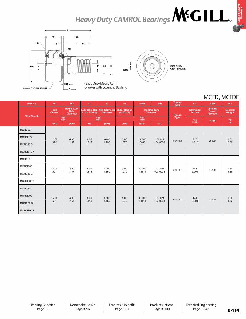
B-114
Ca
m F
oll
ow
er
Be
ari
ng
s
Heavy Duty CAMROL Bearings
B-114
MCFD, MCFDEPart No. RD W SD SL C TL L R ECC G BD
Track Roller Dynamic Rating
Track Roller Static Rating
Part No. HC HD D E Ro HBD sdt Thread Type CT LSD WT
With Shields
Roller Diameter Roller Width Stud Diameter Stud Length
Endplate Extension
Minimum Thread Length
Length Overall
Cylindrical Eccentric
With Shields
Hole Center
Radial Lub. Hole
DiameterLub. Hole Dia. / Lub. Fitting
Min. Clamping Diameter
Outer Radius (suffix X)
Housing Bore Diameter
Thread Type
Clamping Torque
Limiting Speed
(Grease)Bearing WeightSuffix
MCFD-xx-XBase Modifier
MCFDE-xxmm inch
mm inch
mm inch
mm inch
mm inch
mm inch
mm inch N/lb N/lb
mm inch
mm inch
mm inch Nm
in-lb RPM kglbNom. Tol. Nom. Tol. Nom. Tol. (Ref) (Ref) (Ref) (Ref) (Ref) (Ref) +05/-.15
(+.002 / -.006) See Table (Ref) (Ref) (Ref) (Ref) (Ref) Nom. Tol.
MCFD 72
72.000 2.8346
+0/-.050 +0/-.002
29.00 1.142
+0/.12 +0/-.025
24.000 .9449
+0/-.021 +0/-.0008
49.50 1.949
.80 .031
25.00 .984
80.00 3.150
500 20
N/A N/A N/A
46,000 10,342
57,000 12,815
MCFD 72
12.00 .472
4.00 .157
8.00 .315
44.00 1.732
2.00 .079
24.000 .9449
+0/-.021 +0/-.0008 M24x1.5 216
1,912 2,100 1.01 2.23
MCFDE 72 1 .04
22 0.87
28 .10 MCFDE 72
MCFD 72 X+0/-.013
+0/-.0005 CylindricalN/A N/A N/A MCFD 72 X
MCFDE 72 X 1 .04
22 0.87
28 .10 MCFDE 72 X
MCFD 80
80.000 3.1496
+0/-.050 +0/-.002
35.00 1.378
+0/.12 +0/-.029
30.000 1.1811
+0/-.021 +0/-.0008
63.00 2.480
1.00 .039
32.00 1.260
100.00 3.937
500 20
N/A N/A N/A
67,000 15,063
91,000 20,459
MCFD 80
15.00 .591
4.00 .157
8.00 .315
47.00 1.850
2.00 .079
30.000 1.1811
+0/-.021 +0/-.0008 M30x1.5 441
3,903 1,800 1.54 3.39
MCFDE 80 1.5 .06
29 1.14
35 .38 MCFDE 80
MCFD 80 X+0/-.015
+0/-.0006 CylindricalN/A N/A N/A MCFD 80 X
MCFDE 80 X 1.5 .06
29 1.14
35 .38 MCFDE 80 X
MCFD 90
90.000 3.5433
+0/-.050 +0/-.002
35.00 1.378
+0/.12 +0/-.033
30.000 1.1811
+0/-.021 +0/-.0008
63.00 2.480
1.00 .039
32.00 1.260
100.00 3.937
500 20
N/A N/A N/A
67,000 15,063
101,000 22,707
MCFD 90
15.00 .591
4.00 .157
8.00 .315
47.00 1.850
2.00 .079
30.000 1.1811
+0/-.021 +0/-.0008 M30x1.5 441
3,903 1,800 1.96 4.32
MCFDE 90 1.5 .06
29 1.14
35 .38 MCFDE 90
MCFD 90 X+0/-.015
+0/-.0006 CylindricalN/A N/A N/A MCFD 90 X
MCFDE 90 X 1.5 .06
29 1.14
35 .38 MCFDE 90 X
HC
Ro
BEARING CENTERLINE
FRD F BD E
G
C
W SL
TL
L
HD
ECC
500mm CROWN RADIUS
Heavy Duty Metric Cam Follower with Eccentric Bushing
Bearing SelectionPage B-3
Nomenclature AidPage B-96
Features & BenefitsPage B-97
Product OptionsPage B-100
Technical EngineeringPage B-143
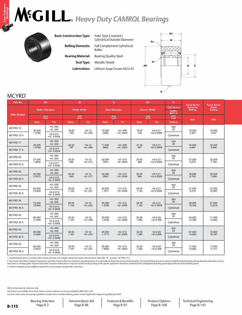
B-115
Ca
m F
oll
ow
er
Be
ari
ng
s
Heavy Duty CAMROL Bearings
B-115
MCYRD
Ro
Ri
R
RD EB
W1
WBasic Construction Type: Yoke Type Crowned /
Cylindrical Outside Diameter
Rolling Elements: Full Complement Cylindrical Roller
Bearing Material: Bearing Quality Steel
Seal Type: Metallic Shield
Lubrication: Lithium Soap Grease NLGI #2
Metric dimensions for reference only.
Not all parts are available from stock. Please contact customer service for availability (800) 626-2120.
For more information on bearing capabilities outside of our standard offering, please contact Application Engineering (800) 626-2093.
1. Standard bearing has a crowned roller outside diameter. For straight cylindrical outside roller diameter, add suffix “X”. Example - MCYRD-15-X.
2. Since load, lubrication method, temperature and other factors affect the maximum operating speed, it is impossible to determine precise limiting speed. The listed limiting speeds are based on lightly loaded bearings having adequate lubrication and are listed only as a design guide. If grease lubricated, frequent relubrication is required. Actual bearing testing in the specific application should be conducted if the anticipated operating speed approaches the listed limiting speed.
3. Positive clamping across endplates required to ensure proper end play after mounting.
Part No. RD W B W1 RTrack Roller
Dynamic Rating
Track Roller Static Rating
E Ro Ri LF LFT TF TFT LSD WT
With Shields
Roller Diameter Roller Width Bore Diameter Overall WidthCylindrical Min. Clamping
Diameter Outer Corner Radius Inner Corner RadiusRecommended Shaft Diameters Limiting Speed
(Grease) Bearing WeightSuffix MCF-X Loose Fit Light Fit
mm inch
mm inch
mm inch
mm inch
mm inch N/lb N/lb
mm inch
mm inch
mm inch
mm inch RPM kg
lbNom. Tol. Nom. Tol. Nom Tol Nom Tol Radius (Ref) (Ref) (Ref) Nom Tol Nom Tol
MCYRD 1535.000 1.3780
+0/-.050 +0/-.002 18.00
.709+0/.12
+0/-.00515.000 .5906
+0/-.008 +0/-.0003
19.00 .748
+0/-0.21 +0/-0.0008
500 20 16,000
3,59718,000 4,047
20.00 .787
.60 .024
.30 .012
14.994 .5903
+0/-.011+0/-.0004
15.000 .5906
+0/-.011+0/-.0004 6,500 .10
.22MCYRD 15 X +0/-0.011
+0/- 0.0004 Cylindrical
MCYRD 1740.000 1.5748
+0/-.050 +0/-.002 20.00
.787+0/.12
+0/-.00917.000 .6693
+0/-.008 +0/-.0003
21.00 .827
+0/-0.21 +0/-0.0008
500 20 18,000
4,04722,000 4,946
22.00 .866
1.00 .039
.30 .012
16.994 .6691
+0/-.011+0/-.0004
17.000.6693
+0/-.011+0/-.0004 5,500 .15
.32MCYRD 17 X +0/-0.011
+0/- 0.0004 Cylindrical
MCYRD 2047.000 1.8504
+0/-.050 +0/-.002 24.00
.945+0/.12
+0/-.01320.000 .7874
+0/-.010 +0/-.0004
25.00 .984
+0/-0.21 +0/-0.0008
500 20 27,000
6,07032,000 7,194
27.00 1.063
1.00 .039
.30 .012
19.993 .7871
+0/-.013 +0/-.0005
20.000 .7874
+0/-.013 +0/-.0005 4,200 .25
.54MCYRD 20 X +0/-0.011
+0/- 0.0004 Cylindrical
MCYRD 2552.000 2.0472
+0/-.050 +0/-.002 24.00
.945+0/.12
+0/-.01725.000 .9843
+0/-.010 +0/-.0004
25.00 .984
+0/-0.21 +0/-0.0008
500 20 30,000
6,74535,000 7,869
31.00 1.220
1.00 .039
.30 .012
24.993 .9840
+0/-.013 +0/-.0005
25.000 .9843
+0/-.013 +0/-.0005 3,400 .28
.62MCYRD 25 X +0/-0.013
+0/- 0.0005 Cylindrical
MCYRD 3062.000 2.4409
+0/-.050 +0/-.002 28.00
1.102+0/.12
+0/-.02130.000 1.1811
+0/-.010 +0/-.0004
29.00 1.142
+0/-0.21 +0/-0.0008
500 20 41,000
9,21847,000 10,567
38.00 1.496
1.00 .039
.30 .012
29.993 1.1808
+0/-.013 +0/-.0005
30.000 1.1811
+0/-.013 +0/-.0005 2,600 .46
1.02MCYRD 30 X +0/-0.013
+0/- 0.0005 Cylindrical
MCYRD 3572.000 2.8346
+0/-.050 +0/-.002 28.00
1.102+0/.12
+0/-.02535.000 1.3780
+0/-.012 +0/-.0005
29.00 1.142
+0/-0.21 +0/-0.0008
500 20 46,000
10,34257,000 12,815
44.00 1.732
1.10 .043
.60 .024
34.991 1.3776
+0/-.016 +0/-.0006
35.000 1.3780
+0/-.016 +0/-.0006 2,100 .63
1.39MCYRD 35 X +0/-0.013
+0/- 0.0005 Cylindrical
MCYRD 4080.000 3.1496
+0/-.050 +0/-.002 30.00
1.181+0/.12
+0/-.02940.000 1.5748
+0/-.012 +0/-.0005
32.00 1.260
+0/-0.25 +0/-0.009
500 20 64,000
14,38871,000 15,962
51.00 2.008
1.10 .043
.60 .024
39.991 1.5744
+0/-.016 +0/-.0006
40.000 1.5748
+0/-.016 +0/-.0006 1,600 .82
1.80MCYRD 40 X +0/-0.015
+0/- 0.0006 Cylindrical
MCYRD 4585.000 3.3465
+0/-.050 +0/-.002 30.00
1.181+0/.12
+0/-.03345.000 1.7717
+0/-.012 +0/-.0005
32.00 1.260
+0/-0.25 +0/-0.009
500 20 67,000
15,06372,000 16,187
55.00 2.165
1.10 .043
.60 .024
44.991 1.7713
+0/-.016 +0/-.0006
45.000 1.7717
+0/-.016 +0/-.0006 1,400 .89
1.95MCYRD 45 X +0/-0.015
+0/- 0.0006 Cylindrical
MCYRD 5090.000 3.5433
+0/-.050 +0/-.002 30.00
1.181+0/.12
+0/-.03750.000 1.9685
+0/-.012 +0/-.0005
32.00 1.260
+0/-0.25 +0/-0.009
500 20 71,000
15,96277,000 17,311
60.00 2.362
1.10 .043
.60 .024
45.991 1.8107
+0/-.016 +0/-.0006
50.000 1.9685
+0/-.016 +0/-.0006 1,300 .95
2.09MCYRD 50 X +0/-0.015
+0/- 0.0006 Cylindrical
Bearing SelectionPage B-3
Nomenclature AidPage B-96
Features & BenefitsPage B-97
Product OptionsPage B-100
Technical EngineeringPage B-143
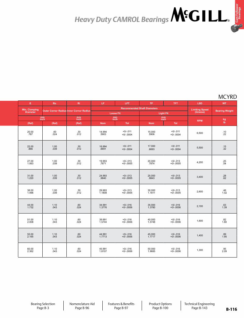
B-116
Ca
m F
oll
ow
er
Be
ari
ng
s
Heavy Duty CAMROL Bearings
B-116
MCYRDPart No. RD W B W1 R
Track Roller Dynamic Rating
Track Roller Static Rating
E Ro Ri LF LFT TF TFT LSD WT
With Shields
Roller Diameter Roller Width Bore Diameter Overall WidthCylindrical Min. Clamping
Diameter Outer Corner Radius Inner Corner RadiusRecommended Shaft Diameters Limiting Speed
(Grease) Bearing WeightSuffix MCF-X Loose Fit Light Fit
mm inch
mm inch
mm inch
mm inch
mm inch N/lb N/lb
mm inch
mm inch
mm inch
mm inch RPM kg
lbNom. Tol. Nom. Tol. Nom Tol Nom Tol Radius (Ref) (Ref) (Ref) Nom Tol Nom Tol
MCYRD 1535.000 1.3780
+0/-.050 +0/-.002 18.00
.709+0/.12
+0/-.00515.000 .5906
+0/-.008 +0/-.0003
19.00 .748
+0/-0.21 +0/-0.0008
500 20 16,000
3,59718,000 4,047
20.00 .787
.60 .024
.30 .012
14.994 .5903
+0/-.011+0/-.0004
15.000 .5906
+0/-.011+0/-.0004 6,500 .10
.22MCYRD 15 X +0/-0.011
+0/- 0.0004 Cylindrical
MCYRD 1740.000 1.5748
+0/-.050 +0/-.002 20.00
.787+0/.12
+0/-.00917.000 .6693
+0/-.008 +0/-.0003
21.00 .827
+0/-0.21 +0/-0.0008
500 20 18,000
4,04722,000 4,946
22.00 .866
1.00 .039
.30 .012
16.994 .6691
+0/-.011+0/-.0004
17.000.6693
+0/-.011+0/-.0004 5,500 .15
.32MCYRD 17 X +0/-0.011
+0/- 0.0004 Cylindrical
MCYRD 2047.000 1.8504
+0/-.050 +0/-.002 24.00
.945+0/.12
+0/-.01320.000 .7874
+0/-.010 +0/-.0004
25.00 .984
+0/-0.21 +0/-0.0008
500 20 27,000
6,07032,000 7,194
27.00 1.063
1.00 .039
.30 .012
19.993 .7871
+0/-.013 +0/-.0005
20.000 .7874
+0/-.013 +0/-.0005 4,200 .25
.54MCYRD 20 X +0/-0.011
+0/- 0.0004 Cylindrical
MCYRD 2552.000 2.0472
+0/-.050 +0/-.002 24.00
.945+0/.12
+0/-.01725.000 .9843
+0/-.010 +0/-.0004
25.00 .984
+0/-0.21 +0/-0.0008
500 20 30,000
6,74535,000 7,869
31.00 1.220
1.00 .039
.30 .012
24.993 .9840
+0/-.013 +0/-.0005
25.000 .9843
+0/-.013 +0/-.0005 3,400 .28
.62MCYRD 25 X +0/-0.013
+0/- 0.0005 Cylindrical
MCYRD 3062.000 2.4409
+0/-.050 +0/-.002 28.00
1.102+0/.12
+0/-.02130.000 1.1811
+0/-.010 +0/-.0004
29.00 1.142
+0/-0.21 +0/-0.0008
500 20 41,000
9,21847,000 10,567
38.00 1.496
1.00 .039
.30 .012
29.993 1.1808
+0/-.013 +0/-.0005
30.000 1.1811
+0/-.013 +0/-.0005 2,600 .46
1.02MCYRD 30 X +0/-0.013
+0/- 0.0005 Cylindrical
MCYRD 3572.000 2.8346
+0/-.050 +0/-.002 28.00
1.102+0/.12
+0/-.02535.000 1.3780
+0/-.012 +0/-.0005
29.00 1.142
+0/-0.21 +0/-0.0008
500 20 46,000
10,34257,000 12,815
44.00 1.732
1.10 .043
.60 .024
34.991 1.3776
+0/-.016 +0/-.0006
35.000 1.3780
+0/-.016 +0/-.0006 2,100 .63
1.39MCYRD 35 X +0/-0.013
+0/- 0.0005 Cylindrical
MCYRD 4080.000 3.1496
+0/-.050 +0/-.002 30.00
1.181+0/.12
+0/-.02940.000 1.5748
+0/-.012 +0/-.0005
32.00 1.260
+0/-0.25 +0/-0.009
500 20 64,000
14,38871,000 15,962
51.00 2.008
1.10 .043
.60 .024
39.991 1.5744
+0/-.016 +0/-.0006
40.000 1.5748
+0/-.016 +0/-.0006 1,600 .82
1.80MCYRD 40 X +0/-0.015
+0/- 0.0006 Cylindrical
MCYRD 4585.000 3.3465
+0/-.050 +0/-.002 30.00
1.181+0/.12
+0/-.03345.000 1.7717
+0/-.012 +0/-.0005
32.00 1.260
+0/-0.25 +0/-0.009
500 20 67,000
15,06372,000 16,187
55.00 2.165
1.10 .043
.60 .024
44.991 1.7713
+0/-.016 +0/-.0006
45.000 1.7717
+0/-.016 +0/-.0006 1,400 .89
1.95MCYRD 45 X +0/-0.015
+0/- 0.0006 Cylindrical
MCYRD 5090.000 3.5433
+0/-.050 +0/-.002 30.00
1.181+0/.12
+0/-.03750.000 1.9685
+0/-.012 +0/-.0005
32.00 1.260
+0/-0.25 +0/-0.009
500 20 71,000
15,96277,000 17,311
60.00 2.362
1.10 .043
.60 .024
45.991 1.8107
+0/-.016 +0/-.0006
50.000 1.9685
+0/-.016 +0/-.0006 1,300 .95
2.09MCYRD 50 X +0/-0.015
+0/- 0.0006 Cylindrical
Bearing SelectionPage B-3
Nomenclature AidPage B-96
Features & BenefitsPage B-97
Product OptionsPage B-100
Technical EngineeringPage B-143
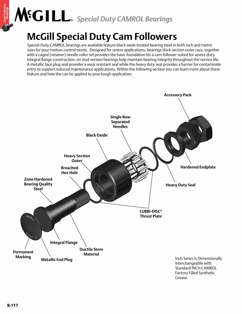
B-117
Ca
m F
oll
ow
er
Be
ari
ng
s
Special Duty CAMROL Bearings
B-117
McGill Special Duty Cam FollowersSpecial-Duty CAMROL bearings are available feature black oxide treated bearing steel in both inch and metric sizes for your motion control needs. Designed for severe applications, bearings thick section outer race, together with a caged (retainer) needle roller set provides the basic foundation for a cam follower suited for severe duty. Integral flange construction, on stud version bearings help maintain bearing integrity throughout the service life. A metallic face plug seal provides a wear resistant seal while the heavy duty seal provides a barrier for contaminate entry to support reduced maintenance applications. Within the following section you can learn more about these feature and how the can be applied to your tough application.
Accessory Pack
Hardened Endplate
Heavy Duty Seal
Single Row Separated
Needles
Zone Hardened Bearing Quality
Steel
Black Oxide
LUBRI-DISC®
Thrust Plate
Ductile Stem Material
Integral Flange
Metallic End Plug
Permanent Marking
Heavy Section Outer
Broached Hex Hole
Inch Series is Dimensionally Interchangeable with Standard INCH CAMROL Factory Filled Synthetic Grease.
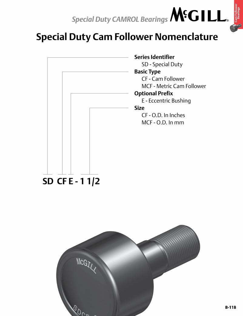
B-118
Ca
m F
oll
ow
er
Be
ari
ng
s
Special Duty CAMROL Bearings
B-118
Special Duty Cam Follower Nomenclature
Series Identifier SD - Special DutyBasic Type CF - Cam Follower MCF - Metric Cam FollowerOptional Prefix E - Eccentric BushingSize CF - O.D. In Inches MCF - O.D. In mm
SD CF E - 1 1/2
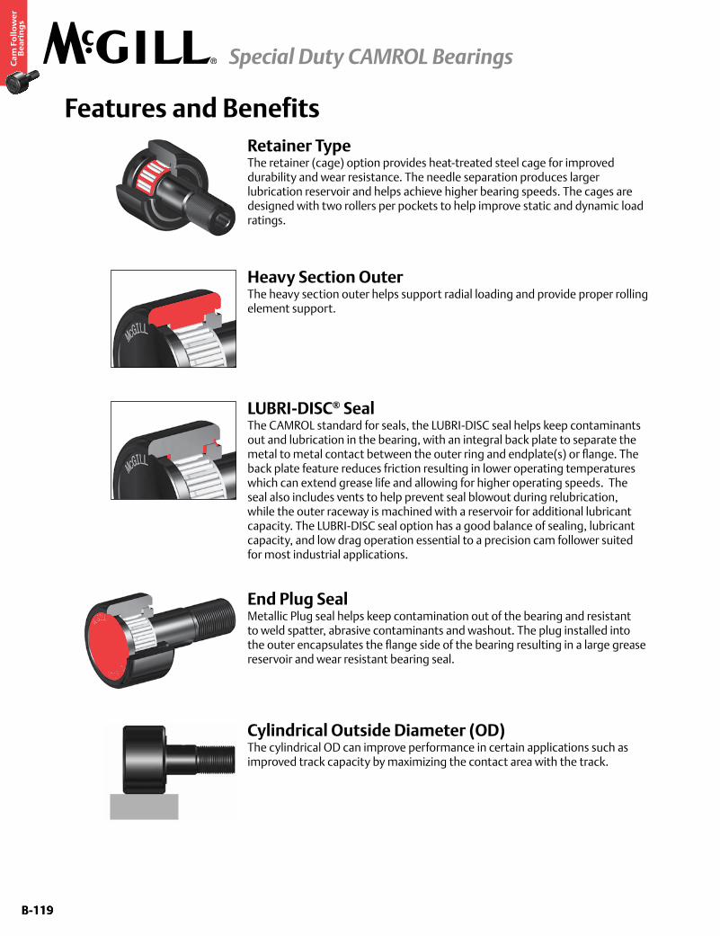
B-119
Ca
m F
oll
ow
er
Be
ari
ng
s
Special Duty CAMROL Bearings
B-119
Features and BenefitsRetainer TypeThe retainer (cage) option provides heat-treated steel cage for improved durability and wear resistance. The needle separation produces larger lubrication reservoir and helps achieve higher bearing speeds. The cages are designed with two rollers per pockets to help improve static and dynamic load ratings.
LUBRI-DISC® SealThe CAMROL standard for seals, the LUBRI-DISC seal helps keep contaminants out and lubrication in the bearing, with an integral back plate to separate the metal to metal contact between the outer ring and endplate(s) or flange. The back plate feature reduces friction resulting in lower operating temperatures which can extend grease life and allowing for higher operating speeds. The seal also includes vents to help prevent seal blowout during relubrication, while the outer raceway is machined with a reservoir for additional lubricant capacity. The LUBRI-DISC seal option has a good balance of sealing, lubricant capacity, and low drag operation essential to a precision cam follower suited for most industrial applications.
Heavy Section OuterThe heavy section outer helps support radial loading and provide proper rolling element support.
End Plug SealMetallic Plug seal helps keep contamination out of the bearing and resistant to weld spatter, abrasive contaminants and washout. The plug installed into the outer encapsulates the flange side of the bearing resulting in a large grease reservoir and wear resistant bearing seal.
Cylindrical Outside Diameter (OD) The cylindrical OD can improve performance in certain applications such as improved track capacity by maximizing the contact area with the track.
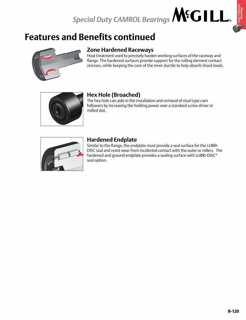
B-120
Ca
m F
oll
ow
er
Be
ari
ng
s
Special Duty CAMROL Bearings
B-120
Zone Hardened RacewaysHeat treatment used to precisely harden working surfaces of the raceway and flange. The hardened surfaces provide support for the rolling element contact stresses, while keeping the core of the inner ductile to help absorb shock loads.
Features and Benefits continued
Hex Hole (Broached)The hex hole can aide in the installation and removal of stud type cam followers by increasing the holding power over a standard screw driver or milled slot.
Hardened EndplateSimilar to the flange, the endplate must provide a seal surface for the LUBRI-DISC seal and resist wear from incidental contact with the outer or rollers. The hardened and ground endplate provides a sealing surface with LUBRI-DISC® seal option.
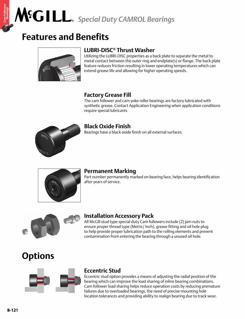
B-121
Ca
m F
oll
ow
er
Be
ari
ng
s
Special Duty CAMROL Bearings
B-121
Installation Accessory PackAll McGill stud type special duty Cam followers include (2) jam nuts to ensure proper thread type (Metric/ Inch), grease fitting and oil hole plug to help provide proper lubrication path to the rolling elements and prevent contamination from entering the bearing through a unused oil hole.
Options
Features and Benefits
Eccentric StudEccentric stud option provides a means of adjusting the radial position of the bearing which can improve the load sharing of inline bearing combinations. Cam follower load sharing helps reduce operation costs by reducing premature failures due to overloaded bearings, the need of precise mounting hole location tolerances and providing ability to realign bearing due to track wear.
Factory Grease FillThe cam follower and cam yoke roller bearings are factory lubricated with synthetic grease. Contact Application Engineering when application conditions require special lubricants
Black Oxide FinishBearings have a black oxide finish on all external surfaces.
Permanent MarkingPart number permanently marked on bearing face, helps bearing identification after years of service.
LUBRI-DISC® Thrust WasherUtilizing the LUBRI-DISC properties as a back plate to separate the metal to metal contact between the outer ring and endplate(s) or flange. The back plate feature reduces friction resulting in lower operating temperatures which can extend grease life and allowing for higher operating speeds.
B-122
Ca
m F
oll
ow
er
Be
ari
ng
s
Special Duty CAMROL Bearings
B-122
Custom Capabilities• Customerspecifiedfactorygreasefill
• Studorthreadlengthmodifications
• Rollerdiametervariationsortolerances
• Camfollowersgroupedormatcheddiametertolerance/runoutsets
• Customengineeredtoorderdesigns
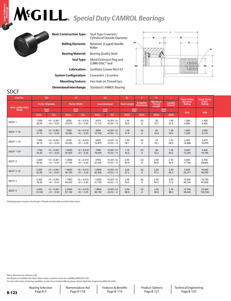
B-123
Ca
m F
oll
ow
er
Be
ari
ng
s
Special Duty CAMROL Bearings
B-123
SDCF
Ro
L
SD
SL
TL
ERD
W
C
H
Basic Construction Type: Stud Type Crowned / Cylindrical Outside Diameter
Rolling Elements: Retained (Caged) Needle Roller
Bearing Material: Bearing Quality Steel
Seal Type: Metal Extension Plug and LUBRI-DISC® Seal
Lubrication: Synthetic Grease NLGI #2
System Configuration: Concentric / Eccentric
Mounting Feature: Hex Hole on Thread Face
Dimensional Interchange: Standard CAMROL Bearing
Metric dimensions for reference only.
Not all parts are available from stock. Please contact customer service for availability (800) 626-2120.
For more information on bearing capabilities outside of our standard offering, please contact Application Engineering (800) 626-2093.
Part No. RD W SD SL C TL L Track Roller Dynamic Rating
Track Roller Static Rating
Part No. H E RoHousing Bore
DiameterThread Type
Clamping Torque
Limiting Speed
WT
With LUBRI-DISC Seals
Roller Diameter Roller Width Stud Diameter Stud Length Endplate Extension
Minimum Thread Length
Length Overall
With LUBRI-DISC Seals
Hex Hole Min. Clamping Diameter
Outer Corner Radius
Bearing Weight
inch mm
inch mm
inch mm
inch mm
inch mm lb/N lb/N
inch mm
inch mm
inch mm in-lb RPM lb
kgNom. Tol. Nom. Tol. Nom. Tol. (Ref) (Ref) (Ref) (Ref) (Ref) (Ref) (Ref) Nom. Tol.
SDCF 1 1.000 25.40
+0 / -0.001 +0 / - 0.03
.6250 15.875
+0 / -0.010 +0 / - 0.25
.4375 11.113
+0.001 /-0 +0.03 / - 0
1.00 25.4
.03 .8
.50 12.7
1.09 27.8
1,280 5,693
1,450 6,450 SDCF 1 .25
6.4.59
15.1.03 .8
.44 11.1
+.0002/-.0003 +.0005/-.0008 7/16-20 250
28 12,500 .16 .07
SDCF 1 1/4 1.250 31.75
+0 / -0.001 +0 / - 0.03
.7500 19.050
+0 / -0.010 +0 / - 0.25
.5000 12.700
+0.001 /-0 +0.03 / - 0
1.25 31.8
.03 .8
.63 15.9
1.28 32.5
1,630 7,250
2,050 9,118 SDCF 1 1/4 .25
6.4.83
21.0.03 .8
.50 12.7
+.0002/-.0003 +.0005/-.0008 1/2-20 350
40 8,100 .29 .13
SDCF 1 1/2 1.500 38.10
+0 / -0.001 +0 / - 0.03
.8750 22.225
+0 / -0.010 +0 / - 0.25
.6250 15.875
+0.001 /-0 +0.03 / - 0
1.50 38.1
.03 .8
.75 19.1
1.53 38.9
2,450 10,898
3,570 15,879 SDCF 1 1/2 .31
7.9.95
24.2.06 1.6
.63 15.9
+.0002/-.0003 +.0005/-.0008 5/8-18 650
73 6,300 .49 .22
SDCF 1 3/4 1.750 44.45
+0 / -0.001 +0 / - 0.03
1.0000 25.400
+0 / -0.010 +0 / - 0.25
.7500 19.050
+0.001 /-0 +0.03 / - 0
1.75 44.5
.03 .8
.88 22.2
1.78 45.2
3,000 13,344
4,450 19,794 SDCF 1 3/4 .31
7.91.11 28.2
.06 1.6
.75 19.1
+.0002/-.0003 +.0005/-.0008 3/4-16 1,250
141 5,000 .80 .36
SDCF 2 2.000 50.80
+0 / -0.001 +0 / - 0.03
1.2500 31.750
+0 / -0.010 +0 / - 0.25
.8750 22.225
+0.001 /-0 +0.03 / - 0
2.00 50.8
.03 .8
2.00 50.8
2.16 54.8
4,000 17,792
6,700 29,802 SDCF 2 .44
11.11.28 32.5
.09 2.4
.88 22.2
+.0002/-.0003 +.0005/-.0008 7/8-14 1,500
170 3,900 1.30 .59
SDCF 2 1/2 2.500 63.50
+0 / -0.001 +0 / - 0.03
1.5000 38.100
+0 / -0.010 +0 / - 0.25
1.0000 25.400
+0.001 /-0 +0.03 / - 0
2.25 57.2
.03 .8
2.25 57.2
2.53 64.3
5,930 26,377
10,400 46,259 SDCF 2 1/2 .50
12.71.56 39.7
.09 2.4
.00 25.4
+.0002/-.0003 +.0005/-.0008 1-14 2,250
254 3,100 2.33 1.06
SDCF 3 3.000 76.20
+0 / -0.001 +0 / - 0.03
1.7500 44.450
+0 / -0.010 +0 / - 0.25
1.2500 31.750
+0.001 /-0 +0.03 / - 0
2.50 63.5
.03 .8
2.50 63.5
3.03 77.0
10,500 46,704
19,700 87,626 SDCF 3 .75
19.12.14 54.4
.13 3.2
.25 31.8
+.0002/-.0003 +.0005/-.0008 1 1/4-12 3,450
390 2,200 3.87 1.76
SDCF 4 4.000 101.60
+0 / -0.001 +0 / - 0.03
2.2500 57.150
+0 / -0.010 +0 / - 0.25
1.5000 38.100
+0.001 /-0 +0.03 / - 0
3.50 88.9
.03 .8
3.50 88.9
3.78 96.0
12,700 56,490
23,200 103,194 SDCF 4 .75
19.12.63 66.7
.13 3.2
.50 38.1
+.0002/-.0003 +.0005/-.0008 1 1/2-12 5,000
565 1,900 8.89 4.03
Bearing SelectionPage B-5
Nomenclature AidPage B-118
Features & BenefitsPage B-119
Product OptionsPage B-121
Technical EngineeringPage B-143
Clamping torque is based on dry threads. If threads are lubricated, use half of value shown.
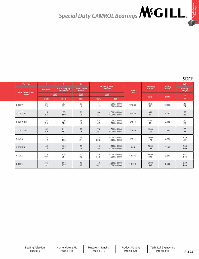
B-124
Ca
m F
oll
ow
er
Be
ari
ng
s
Special Duty CAMROL Bearings
B-124
SDCFPart No. RD W SD SL C TL L Track Roller
Dynamic Rating
Track Roller Static Rating
Part No. H E RoHousing Bore
DiameterThread Type
Clamping Torque
Limiting Speed
WT
With LUBRI-DISC Seals
Roller Diameter Roller Width Stud Diameter Stud Length Endplate Extension
Minimum Thread Length
Length Overall
With LUBRI-DISC Seals
Hex Hole Min. Clamping Diameter
Outer Corner Radius
Bearing Weight
inch mm
inch mm
inch mm
inch mm
inch mm lb/N lb/N
inch mm
inch mm
inch mm in-lb RPM lb
kgNom. Tol. Nom. Tol. Nom. Tol. (Ref) (Ref) (Ref) (Ref) (Ref) (Ref) (Ref) Nom. Tol.
SDCF 1 1.000 25.40
+0 / -0.001 +0 / - 0.03
.6250 15.875
+0 / -0.010 +0 / - 0.25
.4375 11.113
+0.001 /-0 +0.03 / - 0
1.00 25.4
.03 .8
.50 12.7
1.09 27.8
1,280 5,693
1,450 6,450 SDCF 1 .25
6.4.59 15.1
.03 .8
.44 11.1
+.0002/-.0003 +.0005/-.0008 7/16-20 250
28 12,500 .16 .07
SDCF 1 1/4 1.250 31.75
+0 / -0.001 +0 / - 0.03
.7500 19.050
+0 / -0.010 +0 / - 0.25
.5000 12.700
+0.001 /-0 +0.03 / - 0
1.25 31.8
.03 .8
.63 15.9
1.28 32.5
1,630 7,250
2,050 9,118 SDCF 1 1/4 .25
6.4.83 21.0
.03 .8
.50 12.7
+.0002/-.0003 +.0005/-.0008 1/2-20 350
40 8,100 .29 .13
SDCF 1 1/2 1.500 38.10
+0 / -0.001 +0 / - 0.03
.8750 22.225
+0 / -0.010 +0 / - 0.25
.6250 15.875
+0.001 /-0 +0.03 / - 0
1.50 38.1
.03 .8
.75 19.1
1.53 38.9
2,450 10,898
3,570 15,879 SDCF 1 1/2 .31
7.9.95 24.2
.06 1.6
.63 15.9
+.0002/-.0003 +.0005/-.0008 5/8-18 650
73 6,300 .49 .22
SDCF 1 3/4 1.750 44.45
+0 / -0.001 +0 / - 0.03
1.0000 25.400
+0 / -0.010 +0 / - 0.25
.7500 19.050
+0.001 /-0 +0.03 / - 0
1.75 44.5
.03 .8
.88 22.2
1.78 45.2
3,000 13,344
4,450 19,794 SDCF 1 3/4 .31
7.91.11 28.2
.06 1.6
.75 19.1
+.0002/-.0003 +.0005/-.0008 3/4-16 1,250
141 5,000 .80 .36
SDCF 2 2.000 50.80
+0 / -0.001 +0 / - 0.03
1.2500 31.750
+0 / -0.010 +0 / - 0.25
.8750 22.225
+0.001 /-0 +0.03 / - 0
2.00 50.8
.03 .8
2.00 50.8
2.16 54.8
4,000 17,792
6,700 29,802 SDCF 2 .44
11.11.28 32.5
.09 2.4
.88 22.2
+.0002/-.0003 +.0005/-.0008 7/8-14 1,500
170 3,900 1.30 .59
SDCF 2 1/2 2.500 63.50
+0 / -0.001 +0 / - 0.03
1.5000 38.100
+0 / -0.010 +0 / - 0.25
1.0000 25.400
+0.001 /-0 +0.03 / - 0
2.25 57.2
.03 .8
2.25 57.2
2.53 64.3
5,930 26,377
10,400 46,259 SDCF 2 1/2 .50
12.71.56 39.7
.09 2.4
.00 25.4
+.0002/-.0003 +.0005/-.0008 1-14 2,250
254 3,100 2.33 1.06
SDCF 3 3.000 76.20
+0 / -0.001 +0 / - 0.03
1.7500 44.450
+0 / -0.010 +0 / - 0.25
1.2500 31.750
+0.001 /-0 +0.03 / - 0
2.50 63.5
.03 .8
2.50 63.5
3.03 77.0
10,500 46,704
19,700 87,626 SDCF 3 .75
19.12.14 54.4
.13 3.2
.25 31.8
+.0002/-.0003 +.0005/-.0008 1 1/4-12 3,450
390 2,200 3.87 1.76
SDCF 4 4.000 101.60
+0 / -0.001 +0 / - 0.03
2.2500 57.150
+0 / -0.010 +0 / - 0.25
1.5000 38.100
+0.001 /-0 +0.03 / - 0
3.50 88.9
.03 .8
3.50 88.9
3.78 96.0
12,700 56,490
23,200 103,194 SDCF 4 .75
19.12.63 66.7
.13 3.2
.50 38.1
+.0002/-.0003 +.0005/-.0008 1 1/2-12 5,000
565 1,900 8.89 4.03
Bearing SelectionPage B-5
Nomenclature AidPage B-118
Features & BenefitsPage B-119
Product OptionsPage B-121
Technical EngineeringPage B-143
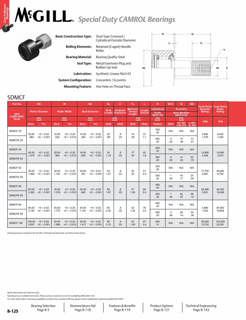
B-125
Ca
m F
oll
ow
er
Be
ari
ng
s
Special Duty CAMROL Bearings
B-125
SDMCF
SD
SL
TL
ERD
W
C
H
Basic Construction Type: Stud Type Crowned / Cylindrical Outside Diameter
Rolling Elements: Retained (Caged) Needle Roller
Bearing Material: Bearing Quality Steel
Seal Type: Metal Extension Plug and Rubber Lip Seal
Lubrication: Synthetic Grease NLGI #2
System Configuration: Concentric / Eccentric
Mounting Feature: Hex Hole on Thread Face
Metric dimensions for reference only.
Not all parts are available from stock. Please contact customer service for availability (800) 626-2120.
For more information on bearing capabilities outside of our standard offering, please contact Application Engineering (800) 626-2093.
Part No. RD W SD SL C TL L R ECC G BDTrack Roller
Dynamic Rating
Track Roller Static Rating
Part No.
H E RoHousing Bore
DiameterThread Type
Clamping Torque
WT
With LUBRI-DISC
Seals
Roller Diameter Roller Width Stud Diameter Stud Length
Endplate Extension
Minimum Thread Length
Length Overall
Cylindrical EccentricHex Hole Min. Clamping
DiameterOuter Corner
RadiusBearing WeightPrefix
SDCF-XXBase Modifier
SDCFE-XXmm inch
mm inch
mm inch
mm inch
mm inch
mm inch
mm inch N/lb N/lb
mm inch
mm inch
mm inch Nm
in-lbkglbNom. Tol. Nom. Tol. Nom. Tol. (Ref) (Ref) (Ref) (Ref) Radius (Ref) +0/-.001
(+0/-.03)± .001 (± .03) (Ref) (Ref) (Ref) Nom. Tol.
SDMCF 2525.00 .984
+0 / -0.02 +0 / - 0.001
16.00 .630
+0 / -0.25 +0 / - 0.010
10.00 .394
+0 / -0.02 +0 / - 0.001
25 .98
.8 .03
14 .55
27 1.1
500 20 N/A N/A N/A
5,690 1,279
6,450 1,450
SDMCF 255
.2015.1 .59
1 .04
10.00 .394
+.025/-.000 +.001/-.000 M10x1.25 57
6.06 .14
SDMCFE 25 500 20
.5 .02
10 .39
13 .51 SDMCFE 25
SDMCF 4040.00 1.575
+0 / -0.02 +0 / - 0.001
25.00 .984
+0 / -0.25 +0 / - 0.010
16.00 .630
+0 / -0.02 +0 / - 0.001
30 1.18
.8 .03
17 .67
42 1.6
500 20 N/A N/A N/A
10,890 2,448
15,900 3,575
SDMCF 408
.3124.1 .95
1 .04
16.00 .630
+.025/-.000 +.001/-.004 M16x1.5 85
10.26 .57
SDMCFE 40 500 20
.5 .02
14 .55
20 .79 SDMCFE 40
SDMCF 5050.00 1.969
+0 / -0.02 +0 / - 0.001
30.00 1.181
+0 / -0.25 +0 / - 0.010
20.00 .787
+0 / -0.02 +0 / - 0.001
40 1.57
.8 .03
22 .87
51 2.0
500 20 N/A N/A N/A
17,750 3,991
29,800 6,700
SDMCF 5010 .39
32.5 1.28
1 .04
20.00 .787
+.025/-.000 +.001/-.008 M20x1.5 85
10.50 1.10
SDMCFE 50 500 20
1 .04
18 .71
24 .94 SDMCFE 50
SDMCF 6060.00 2.362
+0 / -0.02 +0 / - 0.001
35.00 1.378
+0 / -0.25 +0 / - 0.010
24.00 .945
+0 / -0.02 +0 / - 0.001
50 1.97
.8 .03
27 1.06
60 2.4
500 20 N/A N/A N/A
26,380 5,931
46,300 10,409
SDMCF 6012 .47
39.6 1.56
1 .04
24.00 .945
+.025/-.000 +.001/-.012 M24x2 118
13.85 1.86
SDMCFE 60 500 20
1 .04
22 .87
28 .10 SDMCFE 60
SDMCF 8080.00 3.150
+0 / -0.02 +0 / - 0.001
45.00 1.772
+0 / -0.25 +0 / - 0.010
30.00 1.181
+0 / -0.02 +0 / - 0.001
60 2.36
.8 .03
32 1.26
76 3.0
500 20 N/A N/A N/A
4,680 1,052
87,600 19,694
SDMCF 8014 .55
54.2 2.13
2 .08
30.00 .181
+.025/-.000 +.001/-.016 M30x2 118
131.89 4.16
SDMCFE 80 500 20
.5 .06
29 .14
35 .38 SDMCFE 80
SDMCF 100 100.00 3.937
+0 / -0.02 +0 / - 0.001
50.00 1.969
+0 / -0.25 +0 / - 0.010
36.00 1.417
+0 / -0.02 +0 / - 0.001
80 3.15
.8 .03
42 1.65
87 3.4
800 31 N/A N/A N/A 56,500
12,702103,200 23,201 SDMCF 100 17
.6766.5 2.62
2 .08
36.00 .417
+.025/-.000 +.001/-.020 M36x3 118
133.36 7.40
Bearing SelectionPage B-5
Nomenclature AidPage B-118
Features & BenefitsPage B-119
Product OptionsPage B-121
Technical EngineeringPage B-143
Clamping torque is based on dry threads. If threads are lubricated, use half of value shown.
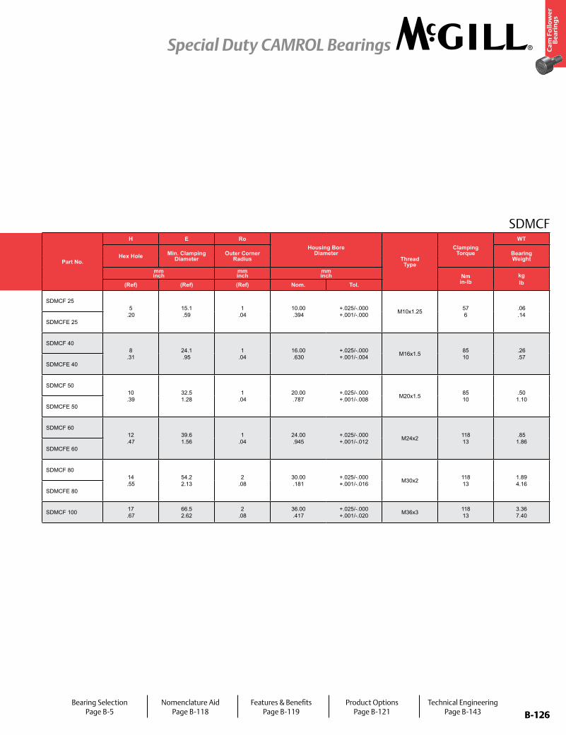
B-126
Ca
m F
oll
ow
er
Be
ari
ng
s
Special Duty CAMROL Bearings
B-126
SDMCFPart No. RD W SD SL C TL L R ECC G BD
Track Roller Dynamic Rating
Track Roller Static Rating
Part No.
H E RoHousing Bore
DiameterThread Type
Clamping Torque
WT
With LUBRI-DISC
Seals
Roller Diameter Roller Width Stud Diameter Stud Length
Endplate Extension
Minimum Thread Length
Length Overall
Cylindrical EccentricHex Hole Min. Clamping
DiameterOuter Corner
RadiusBearing WeightPrefix
SDCF-XXBase Modifier
SDCFE-XXmm inch
mm inch
mm inch
mm inch
mm inch
mm inch
mm inch N/lb N/lb
mm inch
mm inch
mm inch Nm
in-lbkglbNom. Tol. Nom. Tol. Nom. Tol. (Ref) (Ref) (Ref) (Ref) Radius (Ref) +0/-.001
(+0/-.03)± .001 (± .03) (Ref) (Ref) (Ref) Nom. Tol.
SDMCF 2525.00 .984
+0 / -0.02 +0 / - 0.001
16.00 .630
+0 / -0.25 +0 / - 0.010
10.00 .394
+0 / -0.02 +0 / - 0.001
25 .98
.8 .03
14 .55
27 1.1
500 20 N/A N/A N/A
5,690 1,279
6,450 1,450
SDMCF 255
.2015.1 .59
1 .04
10.00 .394
+.025/-.000 +.001/-.000 M10x1.25 57
6.06 .14
SDMCFE 25 500 20
.5 .02
10 .39
13 .51 SDMCFE 25
SDMCF 4040.00 1.575
+0 / -0.02 +0 / - 0.001
25.00 .984
+0 / -0.25 +0 / - 0.010
16.00 .630
+0 / -0.02 +0 / - 0.001
30 1.18
.8 .03
17 .67
42 1.6
500 20 N/A N/A N/A
10,890 2,448
15,900 3,575
SDMCF 408
.3124.1 .95
1 .04
16.00 .630
+.025/-.000 +.001/-.004 M16x1.5 85
10.26 .57
SDMCFE 40 500 20
.5 .02
14 .55
20 .79 SDMCFE 40
SDMCF 5050.00 1.969
+0 / -0.02 +0 / - 0.001
30.00 1.181
+0 / -0.25 +0 / - 0.010
20.00 .787
+0 / -0.02 +0 / - 0.001
40 1.57
.8 .03
22 .87
51 2.0
500 20 N/A N/A N/A
17,750 3,991
29,800 6,700
SDMCF 5010 .39
32.5 1.28
1 .04
20.00 .787
+.025/-.000 +.001/-.008 M20x1.5 85
10.50
1.10SDMCFE 50 500
201
.0418 .71
24 .94 SDMCFE 50
SDMCF 6060.00 2.362
+0 / -0.02 +0 / - 0.001
35.00 1.378
+0 / -0.25 +0 / - 0.010
24.00 .945
+0 / -0.02 +0 / - 0.001
50 1.97
.8 .03
27 1.06
60 2.4
500 20 N/A N/A N/A
26,380 5,931
46,300 10,409
SDMCF 6012 .47
39.6 1.56
1 .04
24.00 .945
+.025/-.000 +.001/-.012 M24x2 118
13.85
1.86SDMCFE 60 500
201
.0422 .87
28 .10 SDMCFE 60
SDMCF 8080.00 3.150
+0 / -0.02 +0 / - 0.001
45.00 1.772
+0 / -0.25 +0 / - 0.010
30.00 1.181
+0 / -0.02 +0 / - 0.001
60 2.36
.8 .03
32 1.26
76 3.0
500 20 N/A N/A N/A
4,680 1,052
87,600 19,694
SDMCF 8014 .55
54.2 2.13
2 .08
30.00 .181
+.025/-.000 +.001/-.016 M30x2 118
131.89 4.16
SDMCFE 80 500 20
.5 .06
29 .14
35 .38 SDMCFE 80
SDMCF 100 100.00 3.937
+0 / -0.02 +0 / - 0.001
50.00 1.969
+0 / -0.25 +0 / - 0.010
36.00 1.417
+0 / -0.02 +0 / - 0.001
80 3.15
.8 .03
42 1.65
87 3.4
800 31 N/A N/A N/A 56,500
12,702103,200 23,201 SDMCF 100 17
.6766.5 2.62
2 .08
36.00 .417
+.025/-.000 +.001/-.020 M36x3 118
133.36 7.40
Bearing SelectionPage B-5
Nomenclature AidPage B-118
Features & BenefitsPage B-119
Product OptionsPage B-121
Technical EngineeringPage B-143
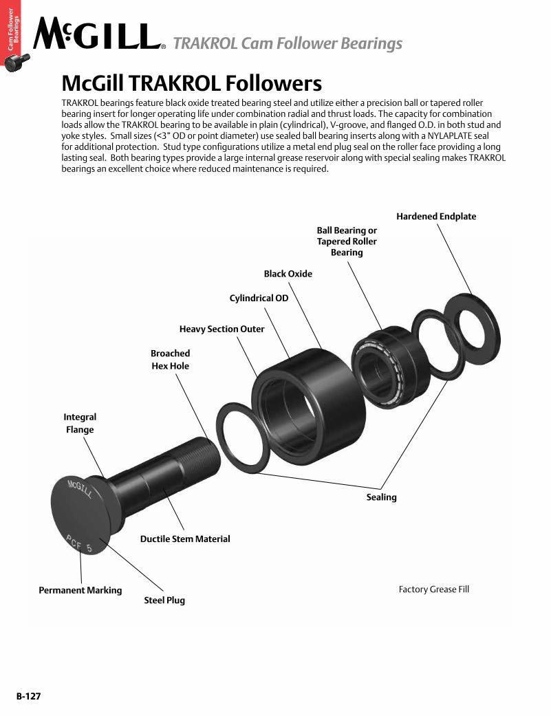
B-127
Ca
m F
oll
ow
er
Be
ari
ng
s
TRAKROL Cam Follower Bearings
B-127
McGill TRAKROL FollowersTRAKROL bearings feature black oxide treated bearing steel and utilize either a precision ball or tapered roller bearing insert for longer operating life under combination radial and thrust loads. The capacity for combination loads allow the TRAKROL bearing to be available in plain (cylindrical), V-groove, and flanged O.D. in both stud and yoke styles. Small sizes (<3” OD or point diameter) use sealed ball bearing inserts along with a NYLAPLATE seal for additional protection. Stud type configurations utilize a metal end plug seal on the roller face providing a long lasting seal. Both bearing types provide a large internal grease reservoir along with special sealing makes TRAKROL bearings an excellent choice where reduced maintenance is required.
Hardened Endplate
Ball Bearing or Tapered Roller
Bearing
Black Oxide
Sealing
Cylindrical OD
Integral Flange
Permanent Marking
Ductile Stem Material
Steel Plug
Heavy Section Outer
Broached Hex Hole
Factory Grease Fill
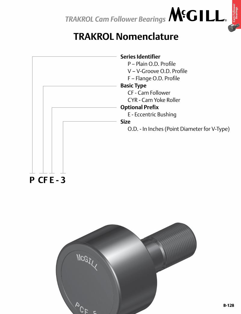
B-128
Ca
m F
oll
ow
er
Be
ari
ng
s
TRAKROL Cam Follower Bearings
B-128
TRAKROL Nomenclature
Series Identifier P – Plain O.D. Profile V – V-Groove O.D. Profile F – Flange O.D. ProfileBasic Type CF - Cam Follower CYR - Cam Yoke RollerOptional Prefix E - Eccentric BushingSize O.D. - In Inches (Point Diameter for V-Type)
P CF E - 3
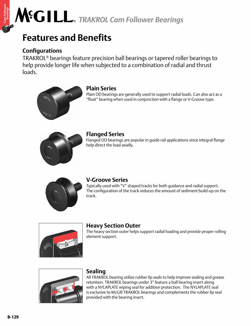
B-129
Ca
m F
oll
ow
er
Be
ari
ng
s
TRAKROL Cam Follower Bearings
B-129
Features and BenefitsConfigurationsTRAKROL® bearings feature precision ball bearings or tapered roller bearings to help provide longer life when subjected to a combination of radial and thrust loads.
SealingAll TRAKROL bearing utilize rubber lip seals to help improve sealing and grease retention. TRAKROL bearings under 3” feature a ball bearing insert along with a NYLAPLATE wiping seal for addition protection. The NYLAPLATE seal is exclusive to McGill TRAKROL bearings and complements the rubber lip seal provided with the bearing insert.
Heavy Section OuterThe heavy section outer helps support radial loading and provide proper rolling element support.
Flanged SeriesFlanged OD bearings are popular in guide rail applications since integral flange help direct the load axially.
Plain SeriesPlain OD bearings are generally used to support radial loads. Can also act as a “float” bearing when used in conjunction with a flange or V-Groove type.
V-Groove SeriesTypically used with “V” shaped tracks for both guidance and radial support. The configuration of the track reduces the amount of sediment build-up on the track.
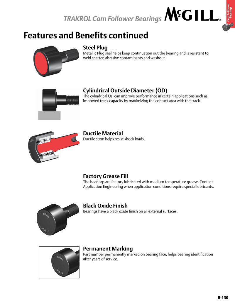
B-130
Ca
m F
oll
ow
er
Be
ari
ng
s
TRAKROL Cam Follower Bearings
B-130
Features and Benefits continued
Ductile MaterialDuctile stem helps resist shock loads.
Black Oxide FinishBearings have a black oxide finish on all external surfaces.
Factory Grease FillThe bearings are factory lubricated with medium temperature grease. Contact Application Engineering when application conditions require special lubricants.
Steel PlugMetallic Plug seal helps keep continuation out the bearing and is resistant to weld spatter, abrasive contaminants and washout.
Permanent MarkingPart number permanently marked on bearing face, helps bearing identification after years of service.
Cylindrical Outside Diameter (OD) The cylindrical OD can improve performance in certain applications such as improved track capacity by maximizing the contact area with the track.
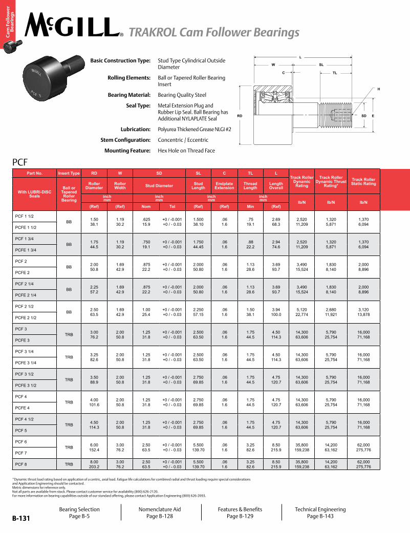
B-131
Ca
m F
oll
ow
er
Be
ari
ng
s
TRAKROL Cam Follower Bearings
B-131
PCF
H
TL
SD
C
W
RD E
SL
LBasic Construction Type: Stud Type Cylindrical Outside
Diameter
Rolling Elements: Ball or Tapered Roller Bearing Insert
Bearing Material: Bearing Quality Steel
Seal Type: Metal Extension Plug and Rubber Lip Seal. Ball Bearing has Additional NYLAPLATE Seal
Lubrication: Polyurea Thickened Grease NLGI #2
Stem Configuration: Concentric / Eccentric
Mounting Feature: Hex Hole on Thread Face
*Dynamic thrust load rating based on application of a centric, axial load. Fatigue life calculations for combined radial and thrust loading require special considerations and Application Engineering should be contacted. Metric dimensions for reference only. Not all parts are available from stock. Please contact customer service for availability (800) 626-2120. For more information on bearing capabilities outside of our standard offering, please contact Application Engineering (800) 626-2093.
Part No. Insert Type RD W SD SL C TL LTrack Roller
Dynamic Rating
Track Roller Dynamic Thrust
Rating*Track Roller Static Rating
Part No. ECC G BD H E Housing Bore
DiameterThread Type
Clamping
Torque
WT
With LUBRI-DISC Seals
Ball or Tapered Roller
Bearing
Roller Diameter
Roller Width Stud Diameter Stud
LengthEndplate Extension
Thread Length
Length Overall
With LUBRI-DISC Seals
EccentricHex Hole Min. Clamping
DiameterBearing WeightBase Modifier
PCFE-XXinch mm
inch mm
inch mm
inch mm lb/N lb/N lb/N
inch mm
inch mm
inch mm in-lb
Nmlbkg(Ref) (Ref) Nom Tol (Ref) (Ref) Min (Ref) (Ref) +0/-.010 ±.001 (Ref) (Ref) Nom. Tol.
PCF 1 1/2BB 1.50
38.11.19 30.2
.625 15.9
+0 / -0.001 +0 / - 0.03
1.500 38.10
.06 1.6
.75 19.1
2.69 68.3
2,520 11,209
1,320 5,871
1,370 6,094
PCF 1 1/2 - - - .2500 6.350
.75 19.1
.6260 15.900 ±.001
±.025 5/8-18 650 74
.51
.23PCFE 1 1/2 PCFE 1 1/2 .03
.8.73
18.5.875 22.2
1.13 28.6
.8780 22.301
PCF 1 3/4BB 1.75
44.51.19 30.2
.750 19.1
+0 / -0.001 +0 / - 0.03
1.750 44.45
.06 1.6
.88 22.2
2.94 74.6
2,520 11,209
1,320 5,871
1,370 6,094
PCF 1 3/4 - - - .2500 6.350
1.00 25.4
.7510 19.075 ±.001
±.025 3/4-16 1,250 142
.81
.37PCFE 1 3/4 PCFE 1 3/4 .03
.8.86
21.71.000 25.4
1.25 31.8
1.0030 25.476
PCF 2BB 2.00
50.81.69 42.9
.875 22.2
+0 / -0.001 +0 / - 0.03
2.000 50.80
.06 1.6
1.13 28.6
3.69 93.7
3,490 15,524
1,830 8,140
2,000 8,896
PCF 2 - - - .3750 9.525
1.00 25.4
.8760 22.250 ±.001
±.025 7/8-14 1,500 170
1.34 .61
PCFE 2 PCFE 2 .03 .8
.98 24.9
1.187 30.1
1.50 38.1
1.1900 30.226
PCF 2 1/4BB 2.25
57.21.69 42.9
.875 22.2
+0 / -0.001 +0 / - 0.03
2.000 50.80
.06 1.6
1.13 28.6
3.69 93.7
3,490 15,524
1,830 8,140
2,000 8,896
PCF 2 1/4 - - - .3750 9.525
1.00 25.4
.8760 22.250 ±.001
±.025 7/8-14 1,500 170
1.72 .78
PCFE 2 1/4 PCFE 2 1/4 .03 .8
.98 24.9
1.187 30.1
1.50 38.1
1.1900 30.226
PCF 2 1/2BB 2.50
63.51.69 42.9
1.00 25.4
+0 / -0.001 +0 / - 0.03
2.250 57.15
.06 1.6
1.50 38.1
3.94 100.0
5,120 22,774
2,680 11,921
3,120 13,878
PCF 2 1/2 - - - .4375 11.113
1.25 31.8
1.0010 25.425 ±.001
±.025 1-14 2,240 254
2.12 .96
PCFE 2 1/2 PCFE 2 1/2 .03 .8
.98 24.9
1.187 30.1
1.50 38.1
1.1900 30.226
PCF 3TRB 3.00
76.22.00 50.8
1.25 31.8
+0 / -0.001 +0 / - 0.03
2.500 63.50
.06 1.6
1.75 44.5
4.50 114.3
14,300 63,606
5,790 25,754
16,000 71,168
PCF 3 - - - .4375 11.113
1.75 44.5
1.2510 31.775 ±.001
±.025 1 1/4-12 3,440 388
3.91 1.77
PCFE 3 PCFE 3 .06 1.5
1.23 31.2
1.750 44.5
2.31 58.7
1.7530 44.526
PCF 3 1/4TRB 3.25
82.62.00 50.8
1.25 31.8
+0 / -0.001 +0 / - 0.03
2.500 63.50
.06 1.6
1.75 44.5
4.50 114.3
14,300 63,606
5,790 25,754
16,000 71,168
PCF 3 1/4 - - - .4375 11.113
1.75 44.5
1.2510 31.775 ±.001
±.025 1 1/4-12 3,440 388
4.60 2.08
PCFE 3 1/4 PCFE 3 1/4 .06 1.5
1.23 31.2
1.750 44.5
2.31 58.7
1.7530 44.526
PCF 3 1/2TRB 3.50
88.92.00 50.8
1.25 31.8
+0 / -0.001 +0 / - 0.03
2.750 69.85
.06 1.6
1.75 44.5
4.75 120.7
14,300 63,606
5,790 25,754
16,000 71,168
PCF 3 1/2 - - - .4375 11.113
1.75 44.5
1.2510 31.775 ±.001
±.025 1 1/4-12 3,440 388
6.25 2.83
PCFE 3 1/2 PCFE 3 1/2 .06 1.5
1.36 34.4
1.812 46.0
2.31 58.7
1.8150 46.101
PCF 4TRB 4.00
101.62.00 50.8
1.25 31.8
+0 / -0.001 +0 / - 0.03
2.750 69.85
.06 1.6
1.75 44.5
4.75 120.7
14,300 63,606
5,790 25,754
16,000 71,168
PCF 4 - - - .4375 11.113
1.75 44.5
1.2510 31.775 ±.001
±.025 1 1/4-12 3,440 388
7.94 3.60
PCFE 4 PCFE 4 .06 1.5
1.36 34.4
1.812 46.0
2.31 58.7
1.8150 46.101
PCF 4 1/2TRB 4.50
114.32.00 50.8
1.25 31.8
+0 / -0.001 +0 / - 0.03
2.750 69.85
.06 1.6
1.75 44.5
4.75 120.7
14,300 63,606
5,790 25,754
16,000 71,168
PCF 4 1/2 - - - .4375 11.113
1.75 44.5
1.2510 31.775 ±.001
±.025 1 1/4-12 3,440 388
9.88 4.48
PCF 5 PCF 5 - - - 3.25 82.6
2.0010 50.825
PCF 6TRB 6.00
152.43.00 76.2
2.50 63.5
+0 / -0.001 +0 / - 0.03
5.500 139.70
.06 1.6
3.25 82.6
8.50 215.9
35,800 159,238
14,200 63,162
62,000 275,776
PCF 6 - - - .8750
22.225
3.25 82.6
2.5010 63.525 ±.001
±.025 2 1/2-12 5,000 566
30.00 13.61
PCF 7 PCF 7 - - - 3.25 82.6
2.5010 63.525
PCF 8 TRB 8.00 203.2
3.00 76.2
2.50 63.5
+0 / -0.001 +0 / - 0.03
5.500 139.70
.06 1.6
3.25 82.6
8.50 215.9
35,800 159,238
14,200 63,162
62,000 275,776 PCF 8 - - - .8750
22.2253.25 82.6
2.5010 63.525
±.001 ±.025 2 1/2-12 5,000
56649.00 22.23
Bearing SelectionPage B-5
Nomenclature AidPage B-128
Features & BenefitsPage B-129
Technical EngineeringPage B-143
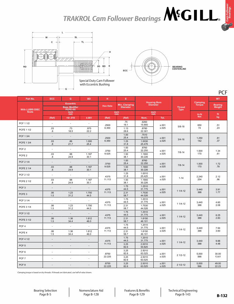
B-132
Ca
m F
oll
ow
er
Be
ari
ng
s
TRAKROL Cam Follower Bearings
B-132
PCF
BEARINGCENTERLINE
BD E
TL
SL
RD
W
G
C
ECC
H
SD
L
Part No. Insert Type RD W SD SL C TL LTrack Roller
Dynamic Rating
Track Roller Dynamic Thrust
Rating*Track Roller Static Rating
Part No. ECC G BD H E Housing Bore
DiameterThread Type
Clamping
Torque
WT
With LUBRI-DISC Seals
Ball or Tapered Roller
Bearing
Roller Diameter
Roller Width Stud Diameter Stud
LengthEndplate Extension
Thread Length
Length Overall
With LUBRI-DISC Seals
EccentricHex Hole Min. Clamping
DiameterBearing WeightBase Modifier
PCFE-XXinch mm
inch mm
inch mm
inch mm lb/N lb/N lb/N
inch mm
inch mm
inch mm in-lb
Nmlbkg(Ref) (Ref) Nom Tol (Ref) (Ref) Min (Ref) (Ref) +0/-.010 ±.001 (Ref) (Ref) Nom. Tol.
PCF 1 1/2BB 1.50
38.11.19 30.2
.625 15.9
+0 / -0.001 +0 / - 0.03
1.500 38.10
.06 1.6
.75 19.1
2.69 68.3
2,520 11,209
1,320 5,871
1,370 6,094
PCF 1 1/2 - - - .2500 6.350
.75 19.1
.6260 15.900 ±.001
±.025 5/8-18 650 74
.51
.23PCFE 1 1/2 PCFE 1 1/2 .03
.8.73 18.5
.875 22.2
1.13 28.6
.8780 22.301
PCF 1 3/4BB 1.75
44.51.19 30.2
.750 19.1
+0 / -0.001 +0 / - 0.03
1.750 44.45
.06 1.6
.88 22.2
2.94 74.6
2,520 11,209
1,320 5,871
1,370 6,094
PCF 1 3/4 - - - .2500 6.350
1.00 25.4
.7510 19.075 ±.001
±.025 3/4-16 1,250 142
.81
.37PCFE 1 3/4 PCFE 1 3/4 .03
.8.86 21.7
1.000 25.4
1.25 31.8
1.0030 25.476
PCF 2BB 2.00
50.81.69 42.9
.875 22.2
+0 / -0.001 +0 / - 0.03
2.000 50.80
.06 1.6
1.13 28.6
3.69 93.7
3,490 15,524
1,830 8,140
2,000 8,896
PCF 2 - - - .3750 9.525
1.00 25.4
.8760 22.250 ±.001
±.025 7/8-14 1,500 170
1.34 .61
PCFE 2 PCFE 2 .03 .8
.98 24.9
1.187 30.1
1.50 38.1
1.1900 30.226
PCF 2 1/4BB 2.25
57.21.69 42.9
.875 22.2
+0 / -0.001 +0 / - 0.03
2.000 50.80
.06 1.6
1.13 28.6
3.69 93.7
3,490 15,524
1,830 8,140
2,000 8,896
PCF 2 1/4 - - - .3750 9.525
1.00 25.4
.8760 22.250 ±.001
±.025 7/8-14 1,500 170
1.72 .78
PCFE 2 1/4 PCFE 2 1/4 .03 .8
.98 24.9
1.187 30.1
1.50 38.1
1.1900 30.226
PCF 2 1/2BB 2.50
63.51.69 42.9
1.00 25.4
+0 / -0.001 +0 / - 0.03
2.250 57.15
.06 1.6
1.50 38.1
3.94 100.0
5,120 22,774
2,680 11,921
3,120 13,878
PCF 2 1/2 - - - .4375 11.113
1.25 31.8
1.0010 25.425 ±.001
±.025 1-14 2,240 254
2.12 .96
PCFE 2 1/2 PCFE 2 1/2 .03 .8
.98 24.9
1.187 30.1
1.50 38.1
1.1900 30.226
PCF 3TRB 3.00
76.22.00 50.8
1.25 31.8
+0 / -0.001 +0 / - 0.03
2.500 63.50
.06 1.6
1.75 44.5
4.50 114.3
14,300 63,606
5,790 25,754
16,000 71,168
PCF 3 - - - .4375 11.113
1.75 44.5
1.2510 31.775 ±.001
±.025 1 1/4-12 3,440 388
3.91 1.77
PCFE 3 PCFE 3 .06 1.5
1.23 31.2
1.750 44.5
2.31 58.7
1.7530 44.526
PCF 3 1/4TRB 3.25
82.62.00 50.8
1.25 31.8
+0 / -0.001 +0 / - 0.03
2.500 63.50
.06 1.6
1.75 44.5
4.50 114.3
14,300 63,606
5,790 25,754
16,000 71,168
PCF 3 1/4 - - - .4375 11.113
1.75 44.5
1.2510 31.775 ±.001
±.025 1 1/4-12 3,440 388
4.60 2.08
PCFE 3 1/4 PCFE 3 1/4 .06 1.5
1.23 31.2
1.750 44.5
2.31 58.7
1.7530 44.526
PCF 3 1/2TRB 3.50
88.92.00 50.8
1.25 31.8
+0 / -0.001 +0 / - 0.03
2.750 69.85
.06 1.6
1.75 44.5
4.75 120.7
14,300 63,606
5,790 25,754
16,000 71,168
PCF 3 1/2 - - - .4375 11.113
1.75 44.5
1.2510 31.775 ±.001
±.025 1 1/4-12 3,440 388
6.25 2.83
PCFE 3 1/2 PCFE 3 1/2 .06 1.5
1.36 34.4
1.812 46.0
2.31 58.7
1.8150 46.101
PCF 4TRB 4.00
101.62.00 50.8
1.25 31.8
+0 / -0.001 +0 / - 0.03
2.750 69.85
.06 1.6
1.75 44.5
4.75 120.7
14,300 63,606
5,790 25,754
16,000 71,168
PCF 4 - - - .4375 11.113
1.75 44.5
1.2510 31.775 ±.001
±.025 1 1/4-12 3,440 388
7.94 3.60
PCFE 4 PCFE 4 .06 1.5
1.36 34.4
1.812 46.0
2.31 58.7
1.8150 46.101
PCF 4 1/2TRB 4.50
114.32.00 50.8
1.25 31.8
+0 / -0.001 +0 / - 0.03
2.750 69.85
.06 1.6
1.75 44.5
4.75 120.7
14,300 63,606
5,790 25,754
16,000 71,168
PCF 4 1/2 - - - .4375 11.113
1.75 44.5
1.2510 31.775 ±.001
±.025 1 1/4-12 3,440 388
9.88 4.48
PCF 5 PCF 5 - - - 3.25 82.6
2.0010 50.825
PCF 6TRB 6.00
152.43.00 76.2
2.50 63.5
+0 / -0.001 +0 / - 0.03
5.500 139.70
.06 1.6
3.25 82.6
8.50 215.9
35,800 159,238
14,200 63,162
62,000 275,776
PCF 6 - - - .8750 22.225
3.25 82.6
2.5010 63.525 ±.001
±.025 2 1/2-12 5,000 566
30.00 13.61
PCF 7 PCF 7 - - - 3.25 82.6
2.5010 63.525
PCF 8 TRB 8.00 203.2
3.00 76.2
2.50 63.5
+0 / -0.001 +0 / - 0.03
5.500 139.70
.06 1.6
3.25 82.6
8.50 215.9
35,800 159,238
14,200 63,162
62,000 275,776 PCF 8 - - - .8750
22.2253.25 82.6
2.5010 63.525
±.001 ±.025 2 1/2-12 5,000
56649.00 22.23
Special Duty Cam Follower with Eccentric Bushing
Bearing SelectionPage B-5
Nomenclature AidPage B-128
Features & BenefitsPage B-129
Technical EngineeringPage B-143
Clamping torque is based on dry threads. If threads are lubricated, use half of value shown.
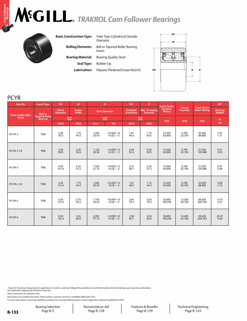
B-133
Ca
m F
oll
ow
er
Be
ari
ng
s
TRAKROL Cam Follower Bearings
B-133
PCYR
EBRD
W1
W
Basic Construction Type: Yoke Type Cylindrical Outside Diameter
Rolling Elements: Ball or Tapered Roller Bearing Insert
Bearing Material: Bearing Quality Steel
Seal Type: Rubber Lip
Lubrication: Polyurea Thickened Grease NLGI #2
*Dynamic thrust load rating based on application of a centric, axial load. Fatigue life calculations for combined radial and thrust loading require special considerations and Application Engineering should be contacted.
Metric dimensions for reference only.
Not all parts are available from stock. Please contact customer service for availability (800) 626-2120.
For more information on bearing capabilities outside of our standard offering, please contact Application Engineering (800) 626-2093.
Part No. Insert Type RD W B W1 ETrack Roller
Dynamic Rating
Thrust Capacity
Track Roller Static Rating
WT
With LUBRI-DISC Seals
Ball or Tapered Roller
Bearing
Roller Diameter
Roller Width Bore Diameter Endplate
ExtensionMin. Clamping
DiameterBearing Weight
inch mm
inch mm
inch mm lb/N lb/N lb/N lb
kg(Ref) (Ref) Nom. Tol. (Ref) (Ref)
PCYR 3 TRB 3.00 76.2
1.75 44.5
1.000 25.40
+0.0007 /-0 +0.02 / - 0
1.81 46.0
1.75 44.5
14,300 63,606
5,790 25,754
20,000 88,960
2.57 1.17
PCYR 3 1/2 TRB 3.50 88.9
2.00 50.8
1.125 28.58
+0.0007 /-0 +0.02 / - 0
2.06 52.4
2.00 50.8
14,300 63,606
5,790 25,754
27,200 120,986
4.41 2.00
PCYR 4 TRB 4.00 101.6
2.25 57.2
1.250 31.75
+0.0007 /-0 +0.02 / - 0
2.31 58.7
2.25 57.2
14,300 63,606
5,790 25,754
27,200 120,986
6.57 2.98
PCYR 4 1/2 TRB 4.50 114.3
1.75 44.5
1.000 25.40
+0.0007 /-0 +0.02 / - 0
1.81 46.0
1.75 44.5
14,300 63,606
5,790 25,754
20,000 88,960
9.09 4.12
PCYR 5 TRB 5.00 127.0
3.75 95.3
1.750 44.45
+0.0007 /-0 +0.02 / - 0
2.85 72.3
3.00 76.2
35,800 159,238
13,300 59,158
58,400 259,763
11.61 5.27
PCYR 6 TRB 6.00 152.4
3.25 82.6
2.250 57.15
+0.0007 /-0 +0.02 / - 0
3.38 85.7
3.25 82.6
35,800 159,238
14,200 63,162
58,400 259,763
20.47 9.29
Bearing SelectionPage B-5
Nomenclature AidPage B-128
Features & BenefitsPage B-129
Technical EngineeringPage B-143

B-134
Ca
m F
oll
ow
er
Be
ari
ng
s
TRAKROL Cam Follower Bearings
B-134
For more information on bearing capabilities outside of our standard offering, please contact Application Engineering (800) 626-2093.
Cam Follower Engineering see page B-147.
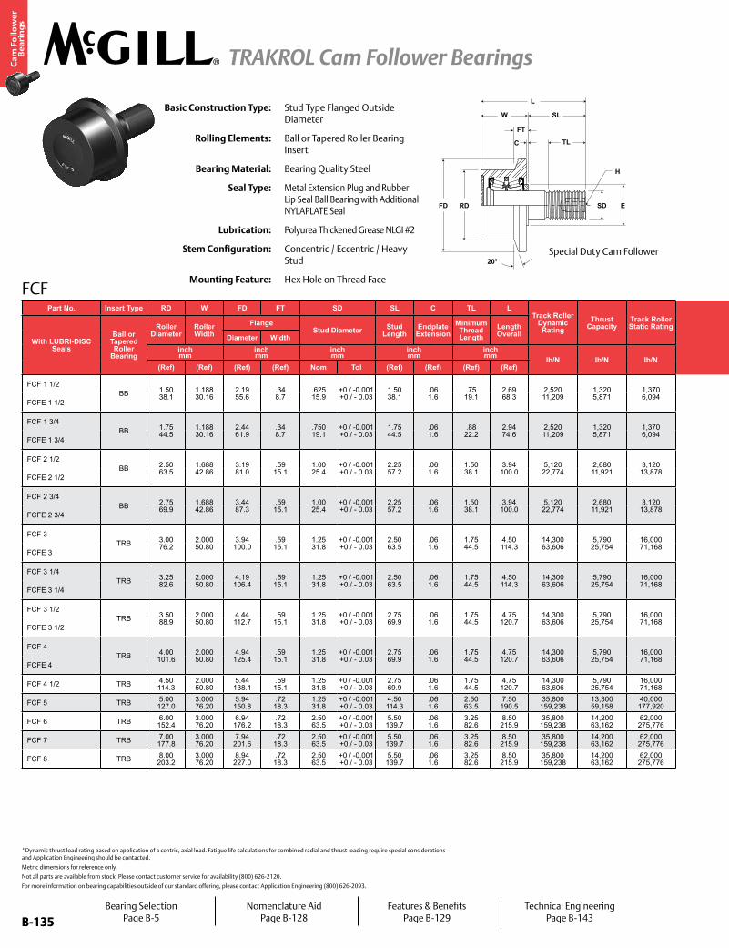
B-135
Ca
m F
oll
ow
er
Be
ari
ng
s
TRAKROL Cam Follower Bearings
B-135
FCF
H
20°
TL
SD
W
FT
FD RD E
SL
C
LBasic Construction Type: Stud Type Flanged Outside
Diameter
Rolling Elements: Ball or Tapered Roller Bearing Insert
Bearing Material: Bearing Quality Steel
Seal Type: Metal Extension Plug and Rubber Lip Seal Ball Bearing with Additional NYLAPLATE Seal
Lubrication: Polyurea Thickened Grease NLGI #2
Stem Configuration: Concentric / Eccentric / Heavy Stud
Mounting Feature: Hex Hole on Thread Face
*Dynamic thrust load rating based on application of a centric, axial load. Fatigue life calculations for combined radial and thrust loading require special considerations and Application Engineering should be contacted.
Metric dimensions for reference only.
Not all parts are available from stock. Please contact customer service for availability (800) 626-2120.
For more information on bearing capabilities outside of our standard offering, please contact Application Engineering (800) 626-2093.
Part No. Insert Type RD W FD FT SD SL C TL LTrack Roller
Dynamic Rating
Thrust Capacity
Track Roller Static Rating
Part No. ECC G BD H E Housing Bore
DiameterThread Type
Clamping
Torque
WT
With LUBRI-DISC Seals
Ball or Tapered Roller
Bearing
Roller Diameter
Roller Width
FlangeStud Diameter Stud
LengthEndplate Extension
Minimum Thread Length
Length Overall
With LUBRI-DISC Seals
EccentricHex Hole Min. Clamping
DiameterBearing WeightDiameter Width Base Modifier
FCFE-XXinch mm
inch mm
inch mm
inch mm
inch mm lb/N lb/N lb/N
inch mm
inch mm
inch mm (Ref) in-lb
Nmlbkg(Ref) (Ref) (Ref) (Ref) Nom Tol (Ref) (Ref) (Ref) (Ref) (Ref) +0/-.010 ±.001 (Ref) (Ref) Nom. Tol.
FCF 1 1/2BB 1.50
38.11.188 30.16
2.19 55.6
.34 8.7
.625 15.9
+0 / -0.001 +0 / - 0.03
1.50 38.1
.06 1.6
.75 19.1
2.69 68.3
2,520 11,209
1,320 5,871
1,370 6,094
FCF 1 1/2 - - - .25 6.4
.75 19.1
.6260 15.900
±.0002 ±.005
5/8-18 650 74
.63 1.4
FCFE 1 1/2 FCFE 1 1/2 .03 .8
.730 18.54
.875 22.23
.878 22.30
+.001 +.025
FCF 1 3/4BB 1.75
44.51.188 30.16
2.44 61.9
.34 8.7
.750 19.1
+0 / -0.001 +0 / - 0.03
1.75 44.5
.06 1.6
.88 22.2
2.94 74.6
2,520 11,209
1,320 5,871
1,370 6,094
FCF 1 3/4 - - - .25 6.4
1.00 25.4
.7510 19.075
±.0002 ±.005
3/4-16 1,250 142
1.00 .45
FCFE 1 3/4 FCFE 1 3/4 .03 .8
0.855 21.72
1.000 25.40
1.003 25.47
+.001 +.025
FCF 2 1/2BB 2.50
63.51.688 42.86
3.19 81.0
.59 15.1
1.00 25.4
+0 / -0.001 +0 / - 0.03
2.25 57.2
.06 1.6
1.50 38.1
3.94 100.0
5,120 22,774
2,680 11,921
3,120 13,878
FCF 2 1/2 - - - .44 11.1
1.25 31.8
1.0010 25.425
±.0002 ±.005
1-14 2,240 254
2.75 1.25
FCFE 2 1/2 FCFE 2 1/2 .03 .8
1.105 28.07
1.375 34.93
1.378 35.00
+.001 +.025
FCF 2 3/4BB 2.75
69.91.688 42.86
3.44 87.3
.59 15.1
1.00 25.4
+0 / -0.001 +0 / - 0.03
2.25 57.2
.06 1.6
1.50 38.1
3.94 100.0
5,120 22,774
2,680 11,921
3,120 13,878
FCF 2 3/4 - - - .44 11.1
1.25 31.8
1.0010 25.425
±.0002 ±.005
1-14 2,240 254
3.25 1.47
FCFE 2 3/4 FCFE 2 3/4 .03 .8
1.105 28.07
1.375 34.93
1.378 35.00
+.001 +.025
FCF 3TRB 3.00
76.22.000 50.80
3.94 100.0
.59 15.1
1.25 31.8
+0 / -0.001 +0 / - 0.03
2.50 63.5
.06 1.6
1.75 44.5
4.50 114.3
14,300 63,606
5,790 25,754
16,000 71,168
FCF 3 - - - .44 11.1
1.75 44.5
1.2510 31.775
±.0002 ±.005
1 1/4-12 3,440 388
4.69 2.13
FCFE 3 FCFE 3 .06 1.5
1.230 31.24
1.750 44.45
1.753 44.52
+.001 +.025
FCF 3 1/4TRB 3.25
82.62.000 50.80
4.19 106.4
.59 15.1
1.25 31.8
+0 / -0.001 +0 / - 0.03
2.50 63.5
.06 1.6
1.75 44.5
4.50 114.3
14,300 63,606
5,790 25,754
16,000 71,168
FCF 3 1/4 - - - .44 11.1
1.75 44.5
1.2510 31.775
±.0002 ±.005
1 1/4-12 3,440 388
5.42 2.46
FCFE 3 1/4 FCFE 3 1/4 .06 1.5
1.230 31.24
1.750 44.45
1.753 44.52
+.001 +.025
FCF 3 1/2TRB 3.50
88.92.000 50.80
4.44 112.7
.59 15.1
1.25 31.8
+0 / -0.001 +0 / - 0.03
2.75 69.9
.06 1.6
1.75 44.5
4.75 120.7
14,300 63,606
5,790 25,754
16,000 71,168
FCF 3 1/2 - - - .44 11.1
1.75 44.5
1.2510 31.775
±.0002 ±.005
1 1/4-12 3,440 388
6.25 2.83
FCFE 3 1/2 FCFE 3 1/2 .06 1.5
1.355 34.42
1.812 46.02
1.815 46.10
+.001 +.025
FCF 4TRB 4.00
101.62.000 50.80
4.94 125.4
.59 15.1
1.25 31.8
+0 / -0.001 +0 / - 0.03
2.75 69.9
.06 1.6
1.75 44.5
4.75 120.7
14,300 63,606
5,790 25,754
16,000 71,168
FCF 4 - - - .44 11.1
1.75 44.5
1.2510 31.775
±.0002 ±.005
1 1/4-12 3,440 388
7.94 3.60
FCFE 4 FCFE 4 .06 1.5
1.355 34.42
1.812 46.02
1.815 46.10
+.001 +.025
FCF 4 1/2 TRB 4.50 114.3
2.000 50.80
5.44 138.1
.59 15.1
1.25 31.8
+0 / -0.001 +0 / - 0.03
2.75 69.9
.06 1.6
1.75 44.5
4.75 120.7
14,300 63,606
5,790 25,754
16,000 71,168 FCF 4 1/2 - - - .44
11.11.75 44.5
1.2510 31.775
±.0002 ±.005 1 1/4-12 3,440
3889.88 4.48
FCF 5 TRB 5.00 127.0
3.000 76.20
5.94 150.8
.72 18.3
1.25 31.8
+0 / -0.001 +0 / - 0.03
4.50 114.3
.06 1.6
2.50 63.5
7.50 190.5
35,800 159,238
13,300 59,158
40,000 177,920 FCF 5 - - - .88
22.23.25 82.6
2.0010 50.825
±.0002 ±.005 2-12 5,000
56618.50 8.39
FCF 6 TRB 6.00 152.4
3.000 76.20
6.94 176.2
.72 18.3
2.50 63.5
+0 / -0.001 +0 / - 0.03
5.50 139.7
.06 1.6
3.25 82.6
8.50 215.9
35,800 159,238
14,200 63,162
62,000 275,776 FCF 6 - - - .88
22.23.25 82.6
2.5010 63.525
±.0002 ±.005 2 1/2-12 5,000
56630.00 13.61
FCF 7 TRB 7.00 177.8
3.000 76.20
7.94 201.6
.72 18.3
2.50 63.5
+0 / -0.001 +0 / - 0.03
5.50 139.7
.06 1.6
3.25 82.6
8.50 215.9
35,800 159,238
14,200 63,162
62,000 275,776 FCF 7 - - - .88
22.23.25 82.6
2.5010 63.525
±.0002 ±.005 2 1/2-12 5,000
56638.00 17.24
FCF 8 TRB 8.00 203.2
3.000 76.20
8.94 227.0
.72 18.3
2.50 63.5
+0 / -0.001 +0 / - 0.03
5.50 139.7
.06 1.6
3.25 82.6
8.50 215.9
35,800 159,238
14,200 63,162
62,000 275,776 FCF 8 - - - .88
22.23.25 82.6
2.5010 63.525
±.0002 ±.005 2 1/2-12 5,000
56649.00 22.23
Special Duty Cam Follower
Bearing SelectionPage B-5
Nomenclature AidPage B-128
Features & BenefitsPage B-129
Technical EngineeringPage B-143
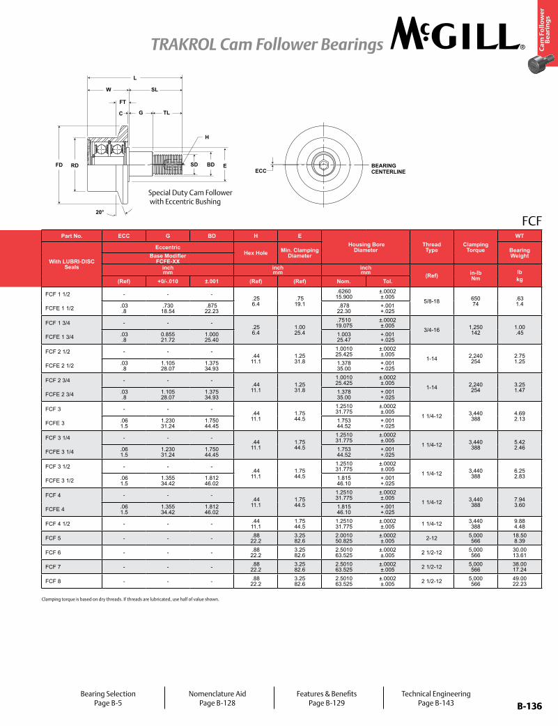
B-136
Ca
m F
oll
ow
er
Be
ari
ng
s
TRAKROL Cam Follower Bearings
B-136
FCF
H
BEARINGCENTERLINE
20°
ECC
G
W
FT
C
FD RD E
SL
TL
BD
L
SD
Part No. Insert Type RD W FD FT SD SL C TL LTrack Roller
Dynamic Rating
Thrust Capacity
Track Roller Static Rating
Part No. ECC G BD H E Housing Bore
DiameterThread Type
Clamping
Torque
WT
With LUBRI-DISC Seals
Ball or Tapered Roller
Bearing
Roller Diameter
Roller Width
FlangeStud Diameter Stud
LengthEndplate Extension
Minimum Thread Length
Length Overall
With LUBRI-DISC Seals
EccentricHex Hole Min. Clamping
DiameterBearing WeightDiameter Width Base Modifier
FCFE-XXinch mm
inch mm
inch mm
inch mm
inch mm lb/N lb/N lb/N
inch mm
inch mm
inch mm (Ref) in-lb
Nmlbkg(Ref) (Ref) (Ref) (Ref) Nom Tol (Ref) (Ref) (Ref) (Ref) (Ref) +0/-.010 ±.001 (Ref) (Ref) Nom. Tol.
FCF 1 1/2BB 1.50
38.11.188 30.16
2.19 55.6
.34 8.7
.625 15.9
+0 / -0.001 +0 / - 0.03
1.50 38.1
.06 1.6
.75 19.1
2.69 68.3
2,520 11,209
1,320 5,871
1,370 6,094
FCF 1 1/2 - - - .25 6.4
.75 19.1
.6260 15.900
±.0002 ±.005
5/8-18 650 74
.63 1.4
FCFE 1 1/2 FCFE 1 1/2 .03 .8
.730 18.54
.875 22.23
.878 22.30
+.001 +.025
FCF 1 3/4BB 1.75
44.51.188 30.16
2.44 61.9
.34 8.7
.750 19.1
+0 / -0.001 +0 / - 0.03
1.75 44.5
.06 1.6
.88 22.2
2.94 74.6
2,520 11,209
1,320 5,871
1,370 6,094
FCF 1 3/4 - - - .25 6.4
1.00 25.4
.7510 19.075
±.0002 ±.005
3/4-16 1,250 142
1.00 .45
FCFE 1 3/4 FCFE 1 3/4 .03 .8
0.855 21.72
1.000 25.40
1.003 25.47
+.001 +.025
FCF 2 1/2BB 2.50
63.51.688 42.86
3.19 81.0
.59 15.1
1.00 25.4
+0 / -0.001 +0 / - 0.03
2.25 57.2
.06 1.6
1.50 38.1
3.94 100.0
5,120 22,774
2,680 11,921
3,120 13,878
FCF 2 1/2 - - - .44 11.1
1.25 31.8
1.0010 25.425
±.0002 ±.005
1-14 2,240 254
2.75 1.25
FCFE 2 1/2 FCFE 2 1/2 .03 .8
1.105 28.07
1.375 34.93
1.378 35.00
+.001 +.025
FCF 2 3/4BB 2.75
69.91.688 42.86
3.44 87.3
.59 15.1
1.00 25.4
+0 / -0.001 +0 / - 0.03
2.25 57.2
.06 1.6
1.50 38.1
3.94 100.0
5,120 22,774
2,680 11,921
3,120 13,878
FCF 2 3/4 - - - .44 11.1
1.25 31.8
1.0010 25.425
±.0002 ±.005
1-14 2,240 254
3.25 1.47
FCFE 2 3/4 FCFE 2 3/4 .03 .8
1.105 28.07
1.375 34.93
1.378 35.00
+.001 +.025
FCF 3TRB 3.00
76.22.000 50.80
3.94 100.0
.59 15.1
1.25 31.8
+0 / -0.001 +0 / - 0.03
2.50 63.5
.06 1.6
1.75 44.5
4.50 114.3
14,300 63,606
5,790 25,754
16,000 71,168
FCF 3 - - - .44 11.1
1.75 44.5
1.2510 31.775
±.0002 ±.005
1 1/4-12 3,440 388
4.69 2.13
FCFE 3 FCFE 3 .06 1.5
1.230 31.24
1.750 44.45
1.753 44.52
+.001 +.025
FCF 3 1/4TRB 3.25
82.62.000 50.80
4.19 106.4
.59 15.1
1.25 31.8
+0 / -0.001 +0 / - 0.03
2.50 63.5
.06 1.6
1.75 44.5
4.50 114.3
14,300 63,606
5,790 25,754
16,000 71,168
FCF 3 1/4 - - - .44 11.1
1.75 44.5
1.2510 31.775
±.0002 ±.005
1 1/4-12 3,440 388
5.42 2.46
FCFE 3 1/4 FCFE 3 1/4 .06 1.5
1.230 31.24
1.750 44.45
1.753 44.52
+.001 +.025
FCF 3 1/2TRB 3.50
88.92.000 50.80
4.44 112.7
.59 15.1
1.25 31.8
+0 / -0.001 +0 / - 0.03
2.75 69.9
.06 1.6
1.75 44.5
4.75 120.7
14,300 63,606
5,790 25,754
16,000 71,168
FCF 3 1/2 - - - .44 11.1
1.75 44.5
1.2510 31.775
±.0002 ±.005
1 1/4-12 3,440 388
6.25 2.83
FCFE 3 1/2 FCFE 3 1/2 .06 1.5
1.355 34.42
1.812 46.02
1.815 46.10
+.001 +.025
FCF 4TRB 4.00
101.62.000 50.80
4.94 125.4
.59 15.1
1.25 31.8
+0 / -0.001 +0 / - 0.03
2.75 69.9
.06 1.6
1.75 44.5
4.75 120.7
14,300 63,606
5,790 25,754
16,000 71,168
FCF 4 - - - .44 11.1
1.75 44.5
1.2510 31.775
±.0002 ±.005
1 1/4-12 3,440 388
7.94 3.60
FCFE 4 FCFE 4 .06 1.5
1.355 34.42
1.812 46.02
1.815 46.10
+.001 +.025
FCF 4 1/2 TRB 4.50 114.3
2.000 50.80
5.44 138.1
.59 15.1
1.25 31.8
+0 / -0.001 +0 / - 0.03
2.75 69.9
.06 1.6
1.75 44.5
4.75 120.7
14,300 63,606
5,790 25,754
16,000 71,168 FCF 4 1/2 - - - .44
11.11.75 44.5
1.2510 31.775
±.0002 ±.005 1 1/4-12 3,440
3889.88 4.48
FCF 5 TRB 5.00 127.0
3.000 76.20
5.94 150.8
.72 18.3
1.25 31.8
+0 / -0.001 +0 / - 0.03
4.50 114.3
.06 1.6
2.50 63.5
7.50 190.5
35,800 159,238
13,300 59,158
40,000 177,920 FCF 5 - - - .88
22.23.25 82.6
2.0010 50.825
±.0002 ±.005 2-12 5,000
56618.50 8.39
FCF 6 TRB 6.00 152.4
3.000 76.20
6.94 176.2
.72 18.3
2.50 63.5
+0 / -0.001 +0 / - 0.03
5.50 139.7
.06 1.6
3.25 82.6
8.50 215.9
35,800 159,238
14,200 63,162
62,000 275,776 FCF 6 - - - .88
22.23.25 82.6
2.5010 63.525
±.0002 ±.005 2 1/2-12 5,000
56630.00 13.61
FCF 7 TRB 7.00 177.8
3.000 76.20
7.94 201.6
.72 18.3
2.50 63.5
+0 / -0.001 +0 / - 0.03
5.50 139.7
.06 1.6
3.25 82.6
8.50 215.9
35,800 159,238
14,200 63,162
62,000 275,776 FCF 7 - - - .88
22.23.25 82.6
2.5010 63.525
±.0002 ±.005 2 1/2-12 5,000
56638.00 17.24
FCF 8 TRB 8.00 203.2
3.000 76.20
8.94 227.0
.72 18.3
2.50 63.5
+0 / -0.001 +0 / - 0.03
5.50 139.7
.06 1.6
3.25 82.6
8.50 215.9
35,800 159,238
14,200 63,162
62,000 275,776 FCF 8 - - - .88
22.23.25 82.6
2.5010 63.525
±.0002 ±.005 2 1/2-12 5,000
56649.00 22.23
Special Duty Cam Follower with Eccentric Bushing
Bearing SelectionPage B-5
Nomenclature AidPage B-128
Features & BenefitsPage B-129
Technical EngineeringPage B-143
Clamping torque is based on dry threads. If threads are lubricated, use half of value shown.
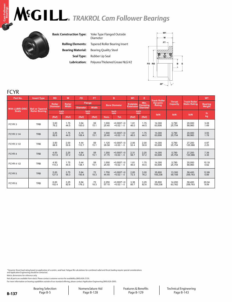
B-137
Ca
m F
oll
ow
er
Be
ari
ng
s
TRAKROL Cam Follower Bearings
B-137
FCYR
FD
FT
B ERD
20°
W1
WBasic Construction Type: Yoke Type Flanged Outside
Diameter
Rolling Elements: Tapered Roller Bearing Insert
Bearing Material: Bearing Quality Steel
Seal Type: Rubber Lip Seal
Lubrication: Polyurea Thickened Grease NLGI #2
*Dynamic thrust load rating based on application of a centric, axial load. Fatigue life calculations for combined radial and thrust loading require special considerations and Application Engineering should be contacted.
Metric dimensions for reference only.
Not all parts are available from stock. Please contact customer service for availability (800) 626-2120.
For more information on bearing capabilities outside of our standard offering, please contact Application Engineering (800) 626-2093.
Part No. Insert Type RD W FD FT B W1 ETrack Roller
Dynamic Rating
Thrust Capacity
Track Roller Static Rating
WT
With LUBRI-DISC Seals
Ball or Tapered Roller Bearing
Roller Diameter
Roller Width
FlangeBore Diameter Endplate
ExtensionMin.
Clamping Diameter
Bearing WeightDiameter Width
inch mm
inch mm
inch mm
inch mm lb/N lb/N lb/N lb
kg(Ref) (Ref) (Ref) (Ref) Nom. Tol. (Ref) (Ref)
FCYR 3 TRB 3.00 76.2
1.75 44.5
3.94 100.0
.59 15.1
1.000 25.40
+0.0007 /-0 +0.02 / - 0
1.81 46.0
1.75 44.5
14,300 63,606
5,790 25,754
20,000 88,960
3.28 1.49
FCYR 3 1/4 TRB 3.25 82.6
1.75 44.5
4.19 106.4
.59 15.1
1.000 25.40
+0.0007 /-0 +0.02 / - 0
1.81 46.0
1.75 44.5
14,300 63,606
5,790 25,754
20,000 88,960
3.93 1.78
FCYR 3 1/2 TRB 3.50 88.9
2.00 50.8
4.44 112.7
.59 15.1
1.125 28.58
+0.0007 /-0 +0.02 / - 0
2.06 52.4
2.00 50.8
14,300 63,606
5,790 25,754
27,200 120,986
4.97 2.25
FCYR 4 TRB 4.00 101.6
2.25 57.2
4.94 125.4
.59 15.1
1.250 31.75
+0.0007 /-0 +0.02 / - 0
2.31 58.7
2.25 57.2
14,300 63,606
5,790 25,754
27,200 120,986
7.39 3.35
FCYR 4 1/2 TRB 4.50 114.3
1.75 44.5
5.44 138.1
.59 15.1
1.000 25.40
+0.0007 /-0 +0.02 / - 0
1.81 46.0
1.75 44.5
14,300 63,606
5,790 25,754
20,000 88,960
10.19 4.62
FCYR 5 TRB 5.00 127.0
3.75 95.3
5.94 150.8
.72 18.3
1.750 44.45
+0.0007 /-0 +0.02 / - 0
2.85 72.3
3.00 76.2
35,800 159,238
13,300 59,158
58,400 259,763
12.99 5.89
FCYR 6 TRB 6.00 152.4
3.25 82.6
6.94 176.2
.72 18.3
2.250 57.15
+0.0007 /-0 +0.02 / - 0
3.38 85.7
3.25 82.6
35,800 159,238
14,200 63,162
58,400 259,763
20.04 9.09
Bearing SelectionPage B-5
Nomenclature AidPage B-128
Features & BenefitsPage B-129
Technical EngineeringPage B-143

B-138
Ca
m F
oll
ow
er
Be
ari
ng
s
TRAKROL Cam Follower Bearings
B-138
For more information on bearing capabilities outside of our standard offering, please contact Application Engineering (800) 626-2093.
Cam Follower Engineering see page B-147.
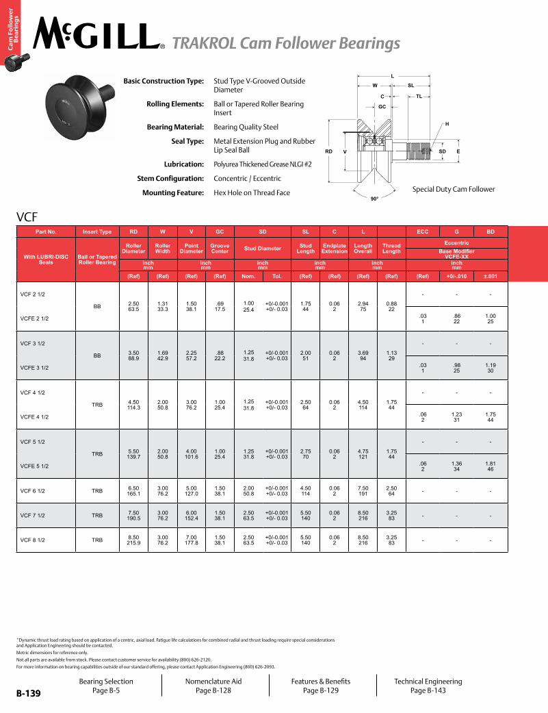
B-139
Ca
m F
oll
ow
er
Be
ari
ng
s
TRAKROL Cam Follower Bearings
B-139
VCF
TL
H
SLW
GC
C
SD
90°
VRD E
LBasic Construction Type: Stud Type V-Grooved Outside
Diameter
Rolling Elements: Ball or Tapered Roller Bearing Insert
Bearing Material: Bearing Quality Steel
Seal Type: Metal Extension Plug and Rubber Lip Seal Ball
Lubrication: Polyurea Thickened Grease NLGI #2
Stem Configuration: Concentric / Eccentric
Mounting Feature: Hex Hole on Thread Face
*Dynamic thrust load rating based on application of a centric, axial load. Fatigue life calculations for combined radial and thrust loading require special considerations and Application Engineering should be contacted.
Metric dimensions for reference only.
Not all parts are available from stock. Please contact customer service for availability (800) 626-2120.
For more information on bearing capabilities outside of our standard offering, please contact Application Engineering (800) 626-2093.
Special Duty Cam Follower
Bearing SelectionPage B-5
Nomenclature AidPage B-128
Features & BenefitsPage B-129
Technical EngineeringPage B-143
Part No. Insert Type RD W V GC SD SL C L ECC G BDTrack Roller
Dynamic RatingThrust
CapacityTrack Roller Static Rating
H E Housing Bore
DiameterThread Type
Clamping Torque
WT
With LUBRI-DISC Seals
Ball or Tapered Roller Bearing
Roller Diameter
Roller Width
Point Diameter
Groove Center Stud Diameter Stud
LengthEndplate Extension
Length Overall
Thread Length
EccentricHex Hole Min. Clamping
Diameter Bearing WeightBase Modifier VCFE-XX
inch mm
inch mm
inch mm
inch mm
inch mm
inch mm lb/N lb/N lb/N
inch mm
inch mm in-lb
Nmlbkg(Ref) (Ref) (Ref) (Ref) Nom. Tol. (Ref) (Ref) (Ref) (Ref) (Ref) +0/-.010 ±.001 (Ref) (Ref) Nom. Tol.
VCF 2 1/2
BB 2.50 63.5
1.31 33.3
1.50 38.1
.69 17.5
1.00 25.4
+0/-0.001 +0/- 0.03
1.75 44
0.06 2
2.94 75
0.88 22
- - -
2,520 11,209
1,320 5,871
1,370 6,094
.25 6
1.0 25
.7510 19
+.0002/-.0003 +.0005/-.0008
3/4-16 1,250 142
1.3 .59
VCFE 2 1/2 .03 1
.86 22
1.00 25
1.003 25.47
±.001 ±.025
VCF 3 1/2
BB 3.50 88.9
1.69 42.9
2.25 57.2
.88 22.2
1.25 31.8
+0/-0.001 +0/- 0.03
2.00 51
0.06 2
3.69 94
1.13 29
- - -
3,490 15,524
1,830 8,140
2,000 8,896
.38 10
1.0 25
.8760 22
+.0002/-.0003 +.0005/-.0010
7/8-14 1,500 170
3.2 1.45
VCFE 3 1/2 .03 1
.98 25
1.19 30
1.190 30.23
±.001 ±.025
VCF 4 1/2
TRB 4.50 114.3
2.00 50.8
3.00 76.2
1.00 25.4
1.25 31.8
+0/-0.001 +0/- 0.03
2.50 64
0.06 2
4.50 114
1.75 44
- - -
14,300 63,606
5,790 25,754
16,000 71,168
.44 11
1.75 44
1.2510 32
+.0002/-.0003 +.0005/-.0013
1 1/4-12 3,440 388
6.8 3.08
VCFE 4 1/2 .06 2
1.23 31
1.75 44
1.75344.52
±.001 ±.025
VCF 5 1/2
TRB 5.50 139.7
2.00 50.8
4.00 101.6
1.00 25.4
1.25 31.8
+0/-0.001 +0/- 0.03
2.75 70
0.06 2
4.75 121
1.75 44
- - -
14,300 63,606
5,790 25,754
16,000 71,168
.44 11
1.75 44
1.2510 32
+.0002/-.0003 +.0005/-.0015
1 1/4-12 3,440 388
10.7 4.85
VCFE 5 1/2 .06 2
1.36 34
1.81 46
1.815 46.10
±.001 ±.025
VCF 6 1/2 TRB 6.50 165.1
3.00 76.2
5.00 127.0
1.50 38.1
2.00 50.8
+0/-0.001 +0/- 0.03
4.50 114
0.06 2
7.50 191
2.50 64 - - - 35,800
159,23813,300 59,158
40,000 177,920
.88 22
3.25 83
2.0010 51
+.0002/-.0003 +.0005/-.0017 2-12 5,000
56626.1 11.84
VCF 7 1/2 TRB 7.50 190.5
3.00 76.2
6.00 152.4
1.50 38.1
2.50 63.5
+0/-0.001 +0/- 0.03
5.50 140
0.06 2
8.50 216
3.25 83 - - - 35,800
159,23814,200 63,162
62,000 275,776
.88 22
3.25 83
2.5010 64
+.0002/-.0003 +.0005/-.0018 2 1/2-12 5,000
56634.0 15.42
VCF 8 1/2 TRB 8.50 215.9
3.00 76.2
7.00 177.8
1.50 38.1
2.50 63.5
+0/-0.001 +0/- 0.03
5.50 140
0.06 2
8.50 216
3.25 83 - - - 35,800
159,23814,200 63,162
62,000 275,776
.88 22
3.25 83
2.5010 64
+.0002/-.0003 +.0005/-.0019 2 1/2-12 5,000
56645.0 20.41
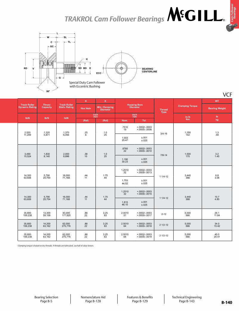
B-140
Ca
m F
oll
ow
er
Be
ari
ng
s
TRAKROL Cam Follower Bearings
B-140
VCF
H
BEARINGCENTERLINE
G
TL
GC
SL
BD
ECC
C
W
90°
VRD ESD
L
Special Duty Cam Follower with Eccentric Bushing
Bearing SelectionPage B-5
Nomenclature AidPage B-128
Features & BenefitsPage B-129
Technical EngineeringPage B-143
Clamping torque is based on dry threads. If threads are lubricated, use half of value shown.
Part No. Insert Type RD W V GC SD SL C L ECC G BDTrack Roller
Dynamic RatingThrust
CapacityTrack Roller Static Rating
H E Housing Bore
DiameterThread Type
Clamping Torque
WT
With LUBRI-DISC Seals
Ball or Tapered Roller Bearing
Roller Diameter
Roller Width
Point Diameter
Groove Center Stud Diameter Stud
LengthEndplate Extension
Length Overall
Thread Length
EccentricHex Hole Min. Clamping
Diameter Bearing WeightBase Modifier VCFE-XX
inch mm
inch mm
inch mm
inch mm
inch mm
inch mm lb/N lb/N lb/N
inch mm
inch mm in-lb
Nmlbkg(Ref) (Ref) (Ref) (Ref) Nom. Tol. (Ref) (Ref) (Ref) (Ref) (Ref) +0/-.010 ±.001 (Ref) (Ref) Nom. Tol.
VCF 2 1/2
BB 2.50 63.5
1.31 33.3
1.50 38.1
.69 17.5
1.00 25.4
+0/-0.001 +0/- 0.03
1.75 44
0.06 2
2.94 75
0.88 22
- - -
2,520 11,209
1,320 5,871
1,370 6,094
.25 6
1.0 25
.7510 19
+.0002/-.0003 +.0005/-.0008
3/4-16 1,250 142
1.3 .59
VCFE 2 1/2 .03 1
.86 22
1.00 25
1.003 25.47
±.001 ±.025
VCF 3 1/2
BB 3.50 88.9
1.69 42.9
2.25 57.2
.88 22.2
1.25 31.8
+0/-0.001 +0/- 0.03
2.00 51
0.06 2
3.69 94
1.13 29
- - -
3,490 15,524
1,830 8,140
2,000 8,896
.38 10
1.0 25
.8760 22
+.0002/-.0003 +.0005/-.0010
7/8-14 1,500 170
3.2 1.45
VCFE 3 1/2 .03 1
.98 25
1.19 30
1.190 30.23
±.001 ±.025
VCF 4 1/2
TRB 4.50 114.3
2.00 50.8
3.00 76.2
1.00 25.4
1.25 31.8
+0/-0.001 +0/- 0.03
2.50 64
0.06 2
4.50 114
1.75 44
- - -
14,300 63,606
5,790 25,754
16,000 71,168
.44 11
1.75 44
1.2510 32
+.0002/-.0003 +.0005/-.0013
1 1/4-12 3,440 388
6.8 3.08
VCFE 4 1/2 .06 2
1.23 31
1.75 44
1.75344.52
±.001 ±.025
VCF 5 1/2
TRB 5.50 139.7
2.00 50.8
4.00 101.6
1.00 25.4
1.25 31.8
+0/-0.001 +0/- 0.03
2.75 70
0.06 2
4.75 121
1.75 44
- - -
14,300 63,606
5,790 25,754
16,000 71,168
.44 11
1.75 44
1.2510 32
+.0002/-.0003 +.0005/-.0015
1 1/4-12 3,440 388
10.7 4.85
VCFE 5 1/2 .06 2
1.36 34
1.81 46
1.815 46.10
±.001 ±.025
VCF 6 1/2 TRB 6.50 165.1
3.00 76.2
5.00 127.0
1.50 38.1
2.00 50.8
+0/-0.001 +0/- 0.03
4.50 114
0.06 2
7.50 191
2.50 64 - - - 35,800
159,23813,300 59,158
40,000 177,920
.88 22
3.25 83
2.0010 51
+.0002/-.0003 +.0005/-.0017 2-12 5,000
56626.1 11.84
VCF 7 1/2 TRB 7.50 190.5
3.00 76.2
6.00 152.4
1.50 38.1
2.50 63.5
+0/-0.001 +0/- 0.03
5.50 140
0.06 2
8.50 216
3.25 83 - - - 35,800
159,23814,200 63,162
62,000 275,776
.88 22
3.25 83
2.5010 64
+.0002/-.0003 +.0005/-.0018 2 1/2-12 5,000
56634.0
15.42
VCF 8 1/2 TRB 8.50 215.9
3.00 76.2
7.00 177.8
1.50 38.1
2.50 63.5
+0/-0.001 +0/- 0.03
5.50 140
0.06 2
8.50 216
3.25 83 - - - 35,800
159,23814,200 63,162
62,000 275,776
.88 22
3.25 83
2.5010 64
+.0002/-.0003 +.0005/-.0019 2 1/2-12 5,000
56645.0
20.41
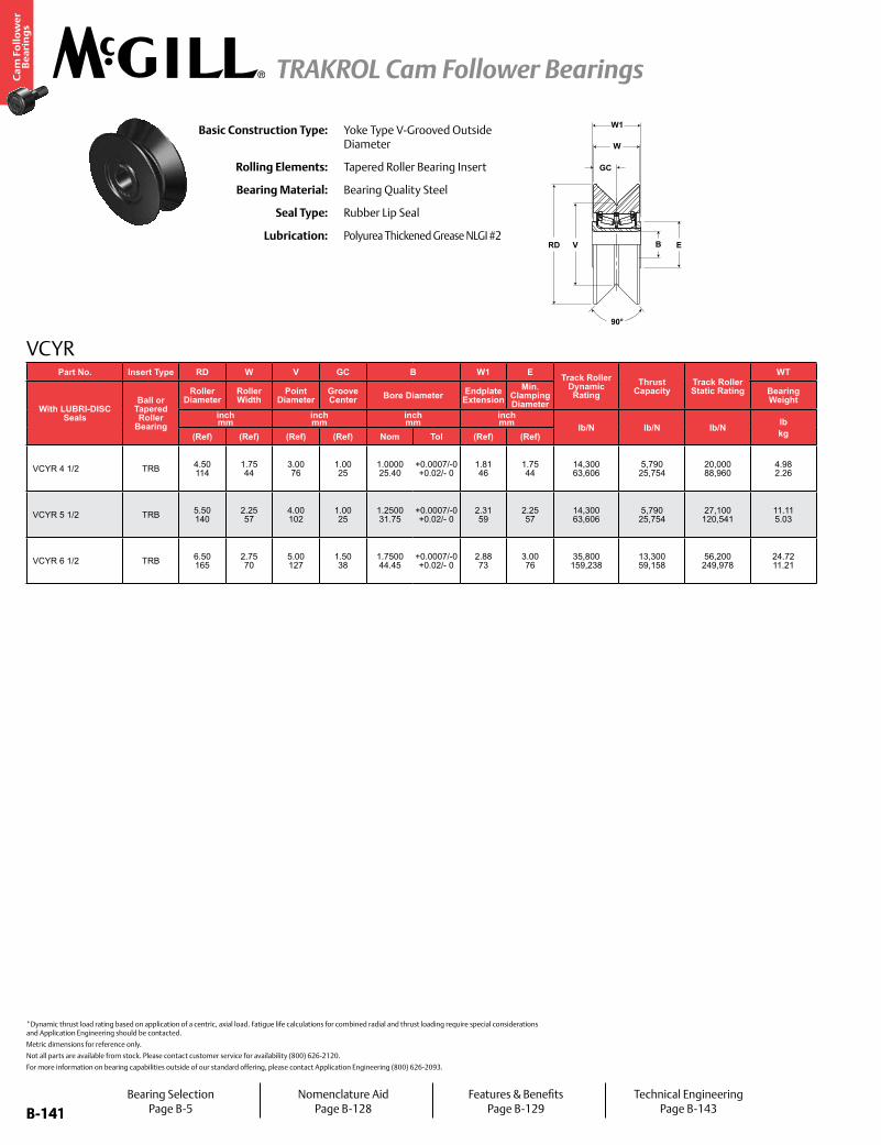
B-141
Ca
m F
oll
ow
er
Be
ari
ng
s
TRAKROL Cam Follower Bearings
B-141
VCYR
B
GC
ERD
W1
W
V
90°
Basic Construction Type: Yoke Type V-Grooved Outside Diameter
Rolling Elements: Tapered Roller Bearing Insert
Bearing Material: Bearing Quality Steel
Seal Type: Rubber Lip Seal
Lubrication: Polyurea Thickened Grease NLGI #2
*Dynamic thrust load rating based on application of a centric, axial load. Fatigue life calculations for combined radial and thrust loading require special considerations and Application Engineering should be contacted.
Metric dimensions for reference only.
Not all parts are available from stock. Please contact customer service for availability (800) 626-2120.
For more information on bearing capabilities outside of our standard offering, please contact Application Engineering (800) 626-2093.
Part No. Insert Type RD W V GC B W1 E Track Roller Dynamic Rating
Thrust Capacity
Track Roller Static Rating
WT
With LUBRI-DISC Seals
Ball or Tapered Roller
Bearing
Roller Diameter
Roller Width
Point Diameter
Groove Center Bore Diameter Endplate
ExtensionMin.
Clamping Diameter
Bearing Weight
inch mm
inch mm
inch mm
inch mm lb/N lb/N lb/N lb
kg(Ref) (Ref) (Ref) (Ref) Nom Tol (Ref) (Ref)
VCYR 4 1/2 TRB 4.50 114
1.75 44
3.00 76
1.00 25
1.0000 25.40
+0.0007/-0 +0.02/- 0
1.81 46
1.75 44
14,300 63,606
5,790 25,754
20,000 88,960
4.98 2.26
VCYR 5 1/2 TRB 5.50 140
2.25 57
4.00 102
1.00 25
1.2500 31.75
+0.0007/-0 +0.02/- 0
2.31 59
2.25 57
14,300 63,606
5,790 25,754
27,100 120,541
11.11 5.03
VCYR 6 1/2 TRB 6.50 165
2.75 70
5.00 127
1.50 38
1.7500 44.45
+0.0007/-0 +0.02/- 0
2.88 73
3.00 76
35,800 159,238
13,300 59,158
56,200 249,978
24.72 11.21
Bearing SelectionPage B-5
Nomenclature AidPage B-128
Features & BenefitsPage B-129
Technical EngineeringPage B-143
B-142
Ca
m F
oll
ow
er
Be
ari
ng
s
TRAKROL Cam Follower Bearings
B-142
For more information on bearing capabilities outside of our standard offering, please contact Application Engineering (800) 626-2093.
Cam Follower Engineering see page B-147.
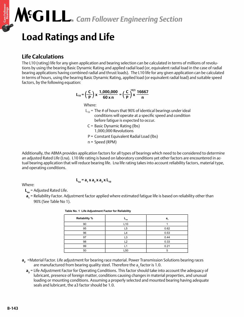
B-143
Ca
m F
oll
ow
er
Be
ari
ng
s
Load Ratings and Life
Life CalculationsThe L10 (rating) life for any given application and bearing selection can be calculated in terms of millions of revolu-tions by using the bearing Basic Dynamic Rating and applied radial load (or, equivalent radial load in the case of radial bearing applications having combined radial and thrust loads). The L10 life for any given application can be calculated in terms of hours, using the bearing Basic Dynamic Rating, applied load (or equivalent radial load) and suitable speed factors, by the following equation:
L10 = x = x
Where: L10 = The # of hours that 90% of identical bearings under ideal conditions will operate at a specific speed and condition before fatigue is expected to occur. C = Basic Dynamic Rating (lbs) 1,000,000 Revolutions P = Constant Equivalent Radial Load (lbs) n = Speed (RPM)
Additionally, the ABMA provides application factors for all types of bearings which need to be considered to determine an adjusted Rated Life (Lna). L10 life rating is based on laboratory conditions yet other factors are encountered in ac-tual bearing application that will reduce bearing life. Lna life rating takes into account reliability factors, material type, and operating conditions.
Lna = a1 x a2 x a3 x L10 Where: Lna = Adjusted Rated Life. a1 = Reliability Factor. Adjustment factor applied where estimated fatigue life is based on reliability other than 90% (See Table No 1).
a2 = Material Factor. Life adjustment for bearing race material. Power Transmission Solutions bearing races are manufactured from bearing quality steel. Therefore the a2 factor is 1.0. a3 = Life Adjustment Factor for Operating Conditions. This factor should take into account the adequacy of lubricant, presence of foreign matter, conditions causing changes in material properties, and unusual loading or mounting conditions. Assuming a properly selected and mounted bearing having adequate seals and lubricant, the a3 factor should be 1.0.
Table No. 1 Life Adjustment Factor for Reliability
Reliability % Lna a1
90 L10 195 L5 0.6296 L4 0.5397 L3 0.4498 L2 0.3399 L1 0.2150 L50 5
CP( ) C
P( )1,000,00060 x n
16667n
10/3
Cam Follower Engineering Section
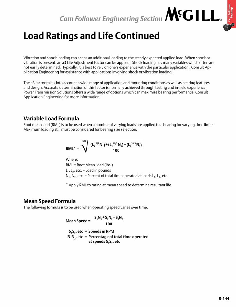
B-144
Ca
m F
oll
ow
er
Be
ari
ng
s
Load Ratings and Life Continued
Vibration and shock loading can act as an additional loading to the steady expected applied load. When shock or vibration is present, an a3 Life Adjustment Factor can be applied. Shock loading has many variables which often are not easily determined. Typically, it is best to rely on one’s experience with the particular application. Consult Ap-plication Engineering for assistance with applications involving shock or vibration loading.
The a3 factor takes into account a wide range of application and mounting conditions as well as bearing features and design. Accurate determination of this factor is normally achieved through testing and in-field experience. Power Transmission Solutions offers a wide range of options which can maximize bearing performance. Consult Application Engineering for more information.
Variable Load FormulaRoot mean load (RML) is to be used when a number of varying loads are applied to a bearing for varying time limits. Maximum loading still must be considered for bearing size selection.
RML* =
Where: RML = Root Mean Load (lbs.) L1, L2, etc. = Load in pounds N1, N2, etc. = Percent of total time operated at loads L1, L2, etc.
* Apply RML to rating at mean speed to determine resultant life.
Mean Speed FormulaThe following formula is to be used when operating speed varies over time.
S1N1 + S2N2 + S3N3
100Mean Speed =
S1S2, etc = Speeds in RPM N1N2, etc = Percentage of total time operated at speeds S1S2, etc
(L110/3 N1) + (L2
10/3 N2) + (L310/3 N3)
100
10/3
Cam Follower Engineering Section
B-145
Ca
m F
oll
ow
er
Be
ari
ng
s
Load Ratings and Life Continued
Bearing Life In Oscillating ApplicationsThe equivalent rotative speed (ERS) is used in life calculations when the bearing does not make complete revolutions during operation. The ERS is then used as the bearing operating speed in the calculation of the L10 (Rating) Life. The formula is based on sufficient angular rotation to have roller paths overlap.
ERS = Equivalent Rotative Speed N = Total number of degrees per minute through which the bearing will rotate. ERS =
In the above formula, allowance is made for the total number of stress applications on the weakest race per unit time, which, in turn, determines fatigue life and the speed factors. The theory behind fretting corrosion is best explained by the fact that the rolling elements in small angles of oscillation retrace a path over an unchanging area of the inner or outer races where the lubricant is prevented by inertia from flowing in behind the roller as the bearing oscillates in one direction. Upon reversal, this small area of rolling contact is traversed by the same roller in the dry state. The friction of the two unlubricated surfaces causes fretting corrosion and produces failures which are unpredictable from a normal life standpoint.
With a given bearing selected for an oscillating application, the best lubrication means is a light mineral oil under positive flow conditions. With a light oil, there is a tendency for all areas in the bearing load zone to be immersed in lu-bricant at all times. The full flow lubrication dictates that any oxidized material which may form is immediately carried away by the lubricant, and since these oxides are abrasive, further wear tends to be avoided. If grease lubrication must be used, it is best to consult with either the bearing manufacturer or the lubricant manufacturer to determine the best possible type of lubricant. Greases have been compounded to resist the detrimental effect of fretting corrosion for such applications.
Static Load RatingThe “static load rating” for rolling element bearings is that uniformly distributed static radial load acting on a non-rotating bearing, which produces a contact stress of 580,000 psi (roller bearings) or 607,000 psi (ball bearings) at the center of the most heavily loaded rolling element. At this stress level, plastic deformation begins to be significant. Ex-perience has shown that the plastic deformation at this stress level can be tolerated in most bearing applications with-out impairment of subsequent bearing operation. In certain applications where subsequent rotation of the bearing is slow and where smoothness and friction requirements are not too exacting, a higher static load limit can be tolerated. Where extreme smoothness is required or friction requirements are critical, a lower static load limit may be necessary.
Minimum Bearing LoadSkidding, or sliding, of the rolling elements on the raceway instead of a true rolling motion can cause excessive wear. Applications with high speeds and light loading are particularly prone to skidding. As a general guideline, rolling ele-ment bearings should be radially loaded at least 2% of Basic Dynamic Rating. For applications where load is light rela-tive to the bearings dynamic load rating, consult Application Engineering for assistance.
N360
Cam Follower Engineering Section
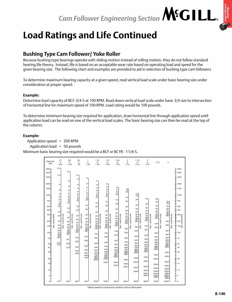
B-146
Ca
m F
oll
ow
er
Be
ari
ng
s
Load Ratings and Life Continued
Bushing Type Cam Follower/ Yoke RollerBecause bushing type bearings operate with sliding motion instead of rolling motion, they do not follow standard bearing life theory. Instead, life is based on an acceptable wear rate based on operating load and speed for the given bearing size. The following chart and examples are provided to aid in selection of bushing type cam followers
To determine maximum bearing capacity at a given speed, read vertical load scale under basic bearing size under consideration at proper speed.
Example:Determine load capacity of BCF-3/4-S at 100 RPM. Read down vertical load scale under basic 3/4 size to intersection of horizontal line for maximum speed of 100 RPM. Load rating would be 100 pounds.
To determine minimum bearing size required for application, draw horizontal line through application speed until application load can be read on one of the vertical load scales. The basic bearing size can then be read at the top of the column.
Example: Application speed = 200 RPM Application load = 50 poundsMinimum basic bearing size required would be a BCF or BCYR - 11/4-S.
Values based on continuous rotation and no lubrication
5
7
10
15
20
30
40
50
70
100
Max
. Spe
ed-R
PM
150
200
300
400
500
700
1000
1500
2000
3000
4000
5000
Roller Dia.(RD)
Max
. Spe
ed-R
PM
5
7
10
15
20
30
40
50
70
100
150
200
300
400
500
700
1000
1500
2000
3000
4000
5000
1/2 &
9/16
170
170150
1009080706050
40
30
20
15
1098765
4
3
2
1.0
0.5
Max
. Loa
d-P
ound
s
5/8 &
11/16
Max
. Loa
d-P
ound
s
270
270
200
150
1009080706050
40
30
20
15
1098765
4
3
2
1.0
3/4 &
7/8
Max
. Loa
d-P
ound
s
480
480400
300
200
150
1009080706050
40
30
20
15
1098765
4
3
2
1.5
1&
1 1/8
Max
. Loa
d-P
ound
s
700
700
400
500600
300
200
150
1009080706050
40
30
20
15
1098765
4
3
2
1 1/4&
1 3/8
Max
. Loa
d-P
ound
s
1000
700800900
1000
400
500600
300
200
150
1009080706050
40
30
20
15
1098765
4
3
1 1/2&
1 5/8
Max
. Loa
d-P
ound
s
1500
700800900
1000
1500
400
500600
300
200
150
1009080706050
40
30
20
15
1098765
4
1 3/4&
1 7/8
Max
. Loa
d-P
ound
s
1900
700800900
1000
1500
1900
400
500600
300
200
150
1009080706050
40
30
20
15
109876
2&
2 1/4
Max
. Loa
d-P
ound
s
2500
700800900
1000
1500
19002500
400
500600
300
200
150
1009080706050
40
30
20
15
1098
2 1/2&
2 3/4
Max
. Loa
d-P
ound
s
4000
700800900
1000
1500
2000
3000
4000
400
500600
300
200
150
1009080706050
40
30
20
1513
3&
3 1/4
Max
. Loa
d-P
ound
s
5800
700800900
1000
1500
2000
3000
4000
50005800
400
500600
300
200
150
1009080706050
40
30
20
3 1/2M
ax. L
oad-
Pou
nds
7500
700800900
1000
1500
2000
3000
4000
5000600070007500
400
500600
300
200
150
100908070605040
3025
4
Max
. Loa
d-P
ound
s
10000
700800900
1000
1500
2000
3000
4000
500060007000800090001000
400
500600
300
200
150
1009080706050
4035
Cam Follower Engineering Section
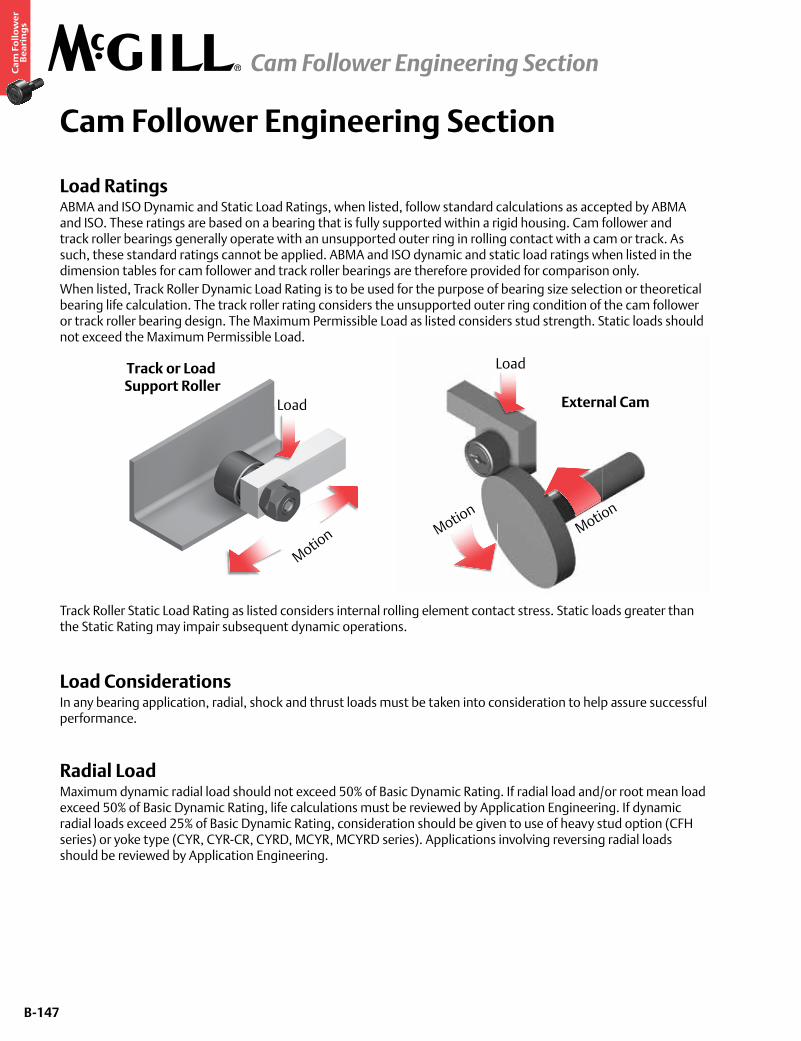
B-147
Ca
m F
oll
ow
er
Be
ari
ng
s
Cam Follower Engineering Section
Load RatingsABMA and ISO Dynamic and Static Load Ratings, when listed, follow standard calculations as accepted by ABMA and ISO. These ratings are based on a bearing that is fully supported within a rigid housing. Cam follower and track roller bearings generally operate with an unsupported outer ring in rolling contact with a cam or track. As such, these standard ratings cannot be applied. ABMA and ISO dynamic and static load ratings when listed in the dimension tables for cam follower and track roller bearings are therefore provided for comparison only.When listed, Track Roller Dynamic Load Rating is to be used for the purpose of bearing size selection or theoretical bearing life calculation. The track roller rating considers the unsupported outer ring condition of the cam follower or track roller bearing design. The Maximum Permissible Load as listed considers stud strength. Static loads should not exceed the Maximum Permissible Load.
Track Roller Static Load Rating as listed considers internal rolling element contact stress. Static loads greater than the Static Rating may impair subsequent dynamic operations.
Load ConsiderationsIn any bearing application, radial, shock and thrust loads must be taken into consideration to help assure successful performance.
Radial LoadMaximum dynamic radial load should not exceed 50% of Basic Dynamic Rating. If radial load and/or root mean load exceed 50% of Basic Dynamic Rating, life calculations must be reviewed by Application Engineering. If dynamic radial loads exceed 25% of Basic Dynamic Rating, consideration should be given to use of heavy stud option (CFH series) or yoke type (CYR, CYR-CR, CYRD, MCYR, MCYRD series). Applications involving reversing radial loads should be reviewed by Application Engineering.
Load
Track or Load Support Roller
Motion
Load
External Cam
Motion
Motion
Cam Follower Engineering Section
B-148
Ca
m F
oll
ow
er
Be
ari
ng
s
Cam Follower Engineering Section continued
Shock LoadThe load ratings in this catalog are based on uniform and steady loading. When the loading is of a shock nature and/or vibration is present, or the loading is indeterminate, a bearing of greater rating must be selected. If such conditions exist, it is advisable to use the Load Factor as shown in the table below. The actual bearing load should be multiplied by the appropriate load factor and the resultant value used to calculate the bearing life or to determine the required Basic Dynamic Rating as described in the General Engineering Section.
Thrust Load Series CF, CFH, CYR, BCF, BCYR, CF-CR, CYR-CR, SDCF, SDMCF, MCF, MCYRDesigned for radial loads, these series’ bearings do not have design features that help them to support thrust loading. Therefore, these cam followers and track rollers should be mounted to minimize, or preferably eliminate, the possibility of any thrust loading on the outer ring.
Series CFD, CYRD, MCFD, MCYRDThese series provide improved thrust capability versus the above needle rolling element and bushing type designs. They are designed using a double row of full complement cylindrical rolling elements. Their construction helps to support incidental thrust sometimes associated with cam follower and track roller applications.
Series PCF, FCF, VCF, PCYR, FCYR, VCYRThese series use radial ball and tapered roller bearing assemblies. These constructions make possible successful bearing operation with various combinations of radial and thrust loads. Refer to dimension tables for specific thrust load ratings.
Track DesignSince either cam followers or cam yoke rollers are merely one component of a two-piece bearing construction involving (1) the cam follower or cam yoke roller and (2) the track or cam on which it operates, some consideration must be given to selection of track or cam materials, since they must be considered bearing components and have a direct effect upon ultimate life and performance of the cam roll application. From the standpoint of track design where bearings are used as support or guide rollers, it is often difficult to obtain high hardness and tensile strength values for the machine members against which the bearings operate. In most applications, in the interest of economy, relatively soft structural materials can be applied. Where dimensional accuracy is not extremely critical, the work hardening of ferrous, low carbon track materials, accompanied by relatively small amounts of wear-in of the bearing into the track surface generally results in satisfactory bearing performance. It is common, for instance, in the application of cam follower or cam yoke roller bearings as lift truck mast rollers to employ formed structural steel sections as bearing track support members. The wearing-in and work hardening of the track surface generally results in a satisfactory bearing application, providing loads are not excessive.
Type of Load Load Factor
Uniform and Constant 1.0
Light Shock 1.5
Moderate Shock 2.0
Heavy Shock 3.0
Cam Follower Engineering Section
B-149
Ca
m F
oll
ow
er
Be
ari
ng
s
Cam Follower Engineering Section continued
Track CapacityTrack capacity of all cam followers and cam yoke roller bearings is the load which a steel track of a given tensile strength will withstand without plastic deformation or brinelling of the track surface. The following tables list track capacities and track capacity factors for steel tracks, as applied to all cam follower and cam yoke roller bearings except crowned O.D. versions. For the crowned O.D. versions, multiply by 0.8 to obtain the track capacity ratings.
To obtain track capacities for a track hardness other than 40 Rockwell “C” scale (180,000 psi or 1242 Mpa tensile strength), multiply the track capacity by the track capacity factor in Table 1. Regardless of the resulting track capacity, dynamic load should not exceed 50% of the dynamic rating as a track roller and static load should not exceed the static rating as a track roller for that bearing.
Table 1 - Track Capacity FactorTrack Tensile Strength, psi
Track Tensile Strength, MPa
Track Hardness Rockwell “C”
Track Capacity Factor
60,000 69 0.11180,000 85 0.198
100,000 95 0.309120,000 828 26 0.445140,000 966 32 0.607160,000 1104 36 0.792180,000 1242 40 1.000200,000 1380 44 1.237220,000 1518 47 1.495240,000 1656 50 1.775260,000 1794 53 2.090280,000 1932 56 2.420300,000 2070 58 2.780
Table 2 - Track Capacity, Inch Series BearingsBasic Bearing
NumberTrack Capacity
Lbs.Basic Bearing
NumberTrack Capacity
Lbs.1/2-N 485 1 7/8 5,415
1/2 530 2 7,350 5/9 595 2 1/4 8,260
5/8-N 725 2 1/2 11,100 5/8 785 2 3/4 12,250 2/3 865 3 15,050 3/4 1,085 3 1/4 16,300 7/8 1,260 3 1/2 20,200
1 1,835 4 26,2001 1/8 2,060 5 38,6001 1/4 2,660 6 55,6001 3/8 2,920 7 75,6001 1/2 3,760 8 94,0001 5/8 4,065 9 118,0001 3/4 5,060 10 145,000
Table 3 - Track Capacity, Metric Series Bearings
Basic Bearing Number
Track Capacity Newtons
Basic Bearing Number
Track Capacity Newtons
M CFR-13-X 2390 M CFR-52-X 24000M CFR-16-X 3675 M CYRR-25-X 24000M CYRR-5-X 3675 M CFD-52-X 24000M CFR-19-X 4360 M CYRD-25-X 24000M CYRR-16 4360 M CFR-62-X 35500M CFR-22-X 5340 M CYRR-30-X 34250M CYRR-8-X 6875 M CFD-62-X 35500M CFR-26-X 6310 M CYRD-30-X 34250M CFR-30-X 7940 M CFR-72-X 39750
M CYRR-10-X 7940 M CYRR-35-X 38125M CFR-32-X 8475 M CFD-72-X 39750
M CYRR-12-X 8475 M CYRD-35-X 38125M CFR-35-X 12300 M CFR-80-X 54750
M CYRR-15-X 12300 M CYRR-40-X 45875M CFD-35-X 12300 M CFD-80-X 54750
M CYRD-15-X 12300 M CYRD-40-X 45875M CFR-40-X 15000 M CFR-85-X 58000
M CYRR-17-X 15000 M CYRR-45-X 48750M CFD-40-X 15000 M CYRD-45-X 48750
M CYRD-17-X 15000 M CFR-90-X 61500M CFR-47-X 21750 M CYRR-50-X 51625
M CYRR-20-X 21750 M CFD-90-X 61500M CFD-47-X 21750 M CYRD-50-X 51625
M CYRD-20-X 21750
Cam Follower Engineering Section

B-150
Ca
m F
oll
ow
er
Be
ari
ng
s
Cam Follower Engineering Section continued
Cam DesignMost cam applications are similar in many respects to the track or support roller applications; however, usually bearing speeds are higher due to the multiplication of cam revolutions per minute by the ratio of the cam O.D. to the cam follower O.D. For cam applications, oil lubrication is preferred due to the tendency towards higher speeds noted above. Where such lubrication methods are not possible, frequent replacement of grease should be followed.
In the application of box or drum cams, it is possible to obtain differential rotation of the cam follower outer race as well as associated load reversals. Unless proper cam hardness and materials are employed as well as ample lubrication, excessive cam or cam follower wear may result. In box cams of this nature, the cam rise and cam fall should be watched closely, since the load reversal encountered can cause shock loads in excess of the capacity of the stud or the bearing. The above precaution would also apply to ordinary circular cams, and instantaneous loads due to rapid cam rise should be carefully calculated and kept below the maximum recommended load or static capacity as listed for the bearing. In ordinary cam design it is possible to employ the most efficient materials for best resistance to fatigue and brinelling. Attainment of high track surface hardnesses associated with good wear resistance are quite feasible. The same general precautions with regard to tensile strength versus hardness, as listed under track design above, should be followed for cam design; and applications involving high marginal bearing or cam loading should be referred to Application Engineering for review.
Cam Follower and Track Roller Bearing LubricationStandard series cam followers and track rollers as listed are factory filled with an NLGI 2 grease suitable for operating temperatures of -20°F to +250°F. Consult Application Engineering regarding grease compatibility issues.
*Authorized by USDA for use in federally inspected meat and poultry plants. USDA H-1 authorized lubricants may be used on equipment as a lubricant or anti-rust film in locations in which there is exposure of the lubricated part to the edible product. Frequency of lubrication depends primarily upon the speed of rotation of the bearing, the type of lubrication employed and the amount of contamination present in the application. It is possible to achieve extended operating life without lubrication where speeds are low and contamination is not excessive. This is primarily true in track support applications where bearing rotation is intermittent. For continuously rotating applications, it is necessary to either provide continuous oil lubrication or else frequent grease lubrication, depending upon the severity of service. Automatic lubrication devices are ideal for intermittent lubrication, since accurate metering of grease and consistent relubrication is maintained through the use of these devices. In applications involving paper dust and other similar abrasive contaminants, relubrication must be resorted to at more frequent intervals and Application Engineering should be consulted for these critical applications. In LUBRI-DISC® sealed cam followers and track rollers, small vents or reliefs are provided in each seal to enable relubrication of the bearing. To avoid loss of seal efficiency, these seal vents are kept as small as possible, and for this reason the rate of relubrication should be kept at lower levels to avoid seal displacement.
Series TypeCF, CFH, CYR, CFD, CYRD, MCF, MCYR, MCFD, MCYRD, Lithium Soap
SDCF, SDMCF Lithium Complex Soap PCF, PCYR, FCF, FCYR, VCF, VCYR (Ball Bearing) Lithium Soap
PCF, PCYR, FCF, FCYR, VCF, VCYR (Tapered Roller Bearing) Polyurea
BCF, BCYR Not grease lubricated, coated with preservative oil.CF-CR, CYR-CR Aluminum Complex Soap USDA H-1 Authorized*
Cam Follower Engineering Section
B-151
Ca
m F
oll
ow
er
Be
ari
ng
s
Cam Follower Engineering Section continued
Reduced Maintenance Cam Followers and Track RollersSeries CFD, CYRD, SDCF, SDMCF, PCF, FCF, VCF cam followers and track rollers are designed for use without relubrication and are not provided as standard with provisions for relubrication. These types of bearings may be limited by the life of the original grease fill and the ability of the seals to protect the bearing from contamination.
Lubrication of Stud-Type Cam Followers and Track RollersSeries CF, CFH, CF-CR, MCF and MCFD cam followers and track rollers with integral studs are supplied with potential for 3 alternate means of lubrication; namely, through either end of the stud with an appropriate grease fitting or through the radial hole in the stem of the stud.• The four smallest sizes in inch series CF, CFH, CF-CR (1/2, 9/16, 5/8 and 11/16) and the three smallest sizes in
metric series MCF (13, 16 and 19) are an exception to the above information, since they contain neither the radial oil hole in the stem nor the axial hole at the threaded end of the stud. Therefore, these bearings may only be lubricated from the flange end of the stud in the screwdriver slot type only.
• The radial oil hole is not present in metric series MCF sizes through 26 mm OD.• Bearings utilizing the hex hole feature, unless noted otherwise on the dimension tables, do not have the axial
lubrication hole present at that end. Since in most cam followers two axial lubrication holes are provided, it is necessary to plug one or both of the holes, depending upon the type of relubrication means employed. For this purpose, oil hole plugs are provided in the bearing wrapping and may be press fitted in the reamed lubrication fitting hole. They are designed to withstand normal relubrication pressures. If the stem radial oil hole is present but not used for relubrication, it should be covered by the housing; therefore, no plug is supplied for this hole.
Grease Lubrication Fittings
Series CF, CFH, CF-CR
Basic Bearing No. Bearing Size
Drive Fitting Size Ref. Alemite No. Fitting
Included1 /2 to 11/16 incl. 1/8” 3019 No3 /4 to 2 3/4 incl. 3/16” 1728-B No
3 to 4 incl. 1/4” 1743-B Yes* 5 to 10 incl. 1/4” NPT 1627-B No
* For hex hole option only.
Series MCF, MCFD
Basic Bearing No. Bearing Size Drive Fitting Size Fitting Included mm
13 3.1 Yes16 to 26 incl. 4 Yes30 to 40 incl. 6 Yes47 to 90 incl. 8 Yes
Lubrication of Yoke-Type Cam Followers and Track RollersThe relubrication of yoke-type cam follower and track roller bearings is straight forward and is accomplished by means of a radial oil hole and annular lubrication groove found on the inner race of the bearing series. The mounting pin for this bearing series must be drilled axially and radially to properly line up with the groove and hole of the CYR bearing inner race to effect proper lubrication.
Cam Follower Engineering Section
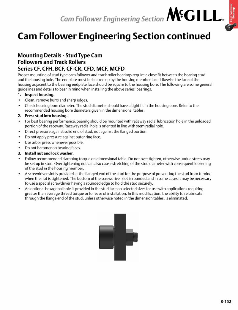
B-152
Ca
m F
oll
ow
er
Be
ari
ng
s
Cam Follower Engineering Section continued
Mounting Details - Stud Type Cam Followers and Track Rollers Series CF, CFH, BCF, CF-CR, CFD, MCF, MCFDProper mounting of stud type cam follower and track roller bearings require a close fit between the bearing stud and the housing hole. The endplate must be backed up by the housing member face. Likewise the face of the housing adjacent to the bearing endplate face should be square to the housing bore. The following are some general guidelines and details to bear in mind when installing the above series’ bearings.1. Inspect housing.• Clean, remove burrs and sharp edges.• Check housing bore diameter. The stud diameter should have a tight fit in the housing bore. Refer to the
recommended housing bore diameters given in the dimensional tables.2. Press stud into housing.• For best bearing performance, bearing should be mounted with raceway radial lubrication hole in the unloaded
portion of the raceway. Raceway radial hole is oriented in line with stem radial hole.• Direct pressure against solid end of stud, not against the flanged portion.• Do not apply pressure against outer ring face.• Use arbor press whenever possible.• Do not hammer on bearing faces.3. Install nut and lock washer.• Follow recommended clamping torque on dimensional table. Do not over tighten, otherwise undue stress may
be set up in stud. Overtightening nut can also cause stretching of the stud diameter with consequent loosening of the stud in the housing member.
• A screwdriver slot is provided at the flanged end of the stud for the purpose of preventing the stud from turning when the nut is tightened. The bottom of the screwdriver slot is rounded and in some cases it may be necessary to use a special screwdriver having a rounded edge to hold the stud securely.
• An optional hexagonal hole is provided in the stud face on selected sizes for use with applications requiring greater than average thread torque or for ease of installation. In this modification, the ability to relubricate through the flange end of the stud, unless otherwise noted in the dimension tables, is eliminated.
Cam Follower Engineering Section
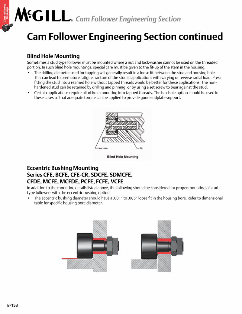
B-153
Ca
m F
oll
ow
er
Be
ari
ng
s
Cam Follower Engineering Section continued
Blind Hole MountingSometimes a stud type follower must be mounted where a nut and lock-washer cannot be used on the threaded portion. In such blind hole mountings, special care must be given to the fit-up of the stem in the housing.• The drilling diameter used for tapping will generally result in a loose fit between the stud and housing hole.
This can lead to premature fatigue fracture of the stud in applications with varying or reverse radial load. Press fitting the stud into a reamed hole without tapped threads would be better for these applications. The non-hardened stud can be retained by drilling and pinning, or by using a set screw to bear against the stud.
• Certain applications require blind hole mounting into tapped threads. The hex hole option should be used in these cases so that adequate torque can be applied to provide good endplate support.
Eccentric Bushing Mounting Series CFE, BCFE, CFE-CR, SDCFE, SDMCFE, CFDE, MCFE, MCFDE, PCFE, FCFE, VCFEIn addition to the mounting details listed above, the following should be considered for proper mounting of stud type followers with the eccentric bushing option.• The eccentric bushing diameter should have a .001” to .005” loose fit in the housing bore. Refer to dimensional
table for specific housing bore diameter.
Cam Follower Engineering Section
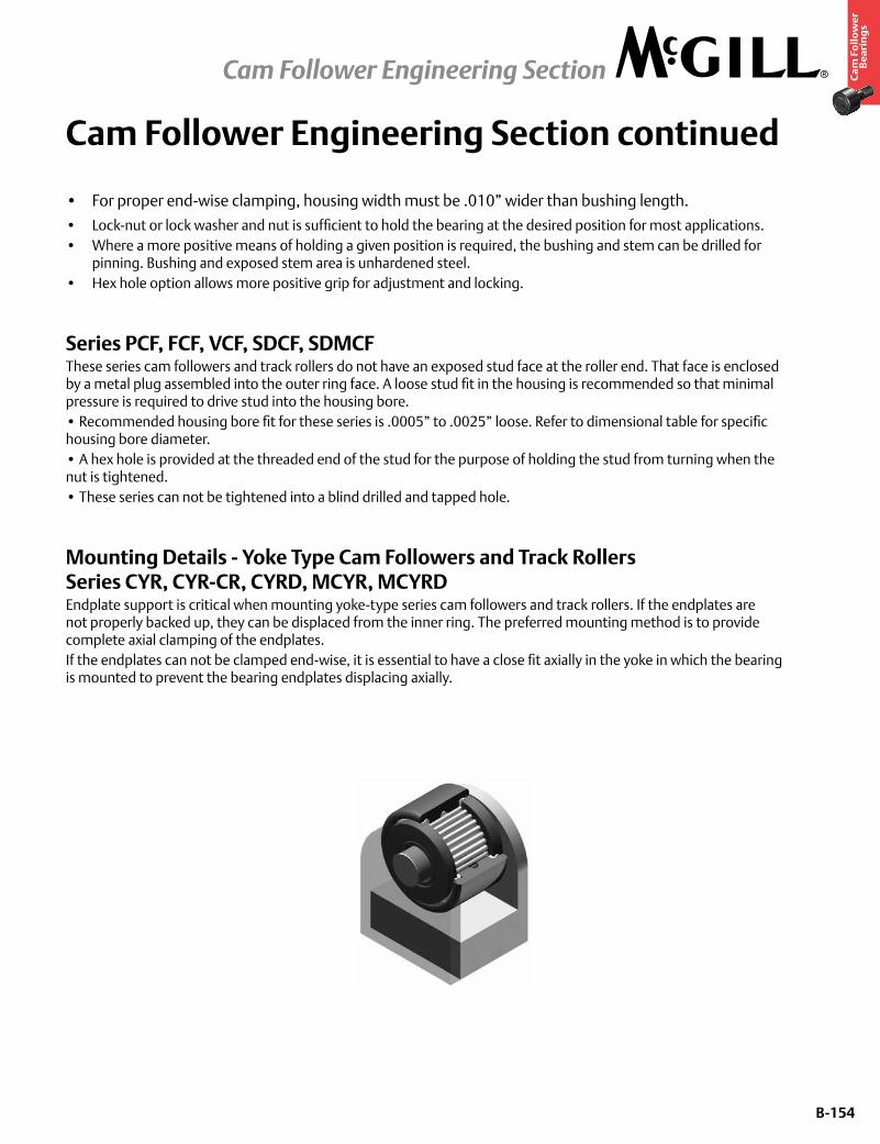
B-154
Ca
m F
oll
ow
er
Be
ari
ng
s
Cam Follower Engineering Section continued
• For proper end-wise clamping, housing width must be .010” wider than bushing length.
• Lock-nut or lock washer and nut is sufficient to hold the bearing at the desired position for most applications.• Where a more positive means of holding a given position is required, the bushing and stem can be drilled for
pinning. Bushing and exposed stem area is unhardened steel.• Hex hole option allows more positive grip for adjustment and locking.
Series PCF, FCF, VCF, SDCF, SDMCFThese series cam followers and track rollers do not have an exposed stud face at the roller end. That face is enclosed by a metal plug assembled into the outer ring face. A loose stud fit in the housing is recommended so that minimal pressure is required to drive stud into the housing bore.• Recommended housing bore fit for these series is .0005” to .0025” loose. Refer to dimensional table for specific housing bore diameter.• A hex hole is provided at the threaded end of the stud for the purpose of holding the stud from turning when the nut is tightened.• These series can not be tightened into a blind drilled and tapped hole.
Mounting Details - Yoke Type Cam Followers and Track Rollers Series CYR, CYR-CR, CYRD, MCYR, MCYRDEndplate support is critical when mounting yoke-type series cam followers and track rollers. If the endplates are not properly backed up, they can be displaced from the inner ring. The preferred mounting method is to provide complete axial clamping of the endplates.If the endplates can not be clamped end-wise, it is essential to have a close fit axially in the yoke in which the bearing is mounted to prevent the bearing endplates displacing axially.
Cam Follower Engineering Section
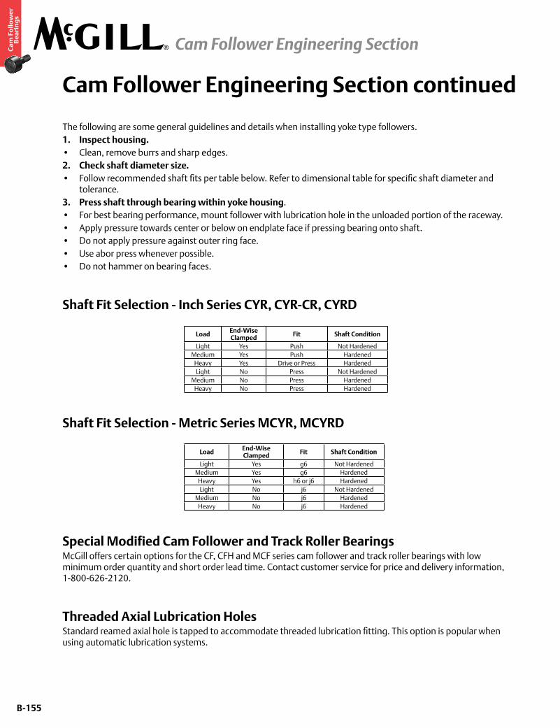
B-155
Ca
m F
oll
ow
er
Be
ari
ng
s
Cam Follower Engineering Section continued
The following are some general guidelines and details when installing yoke type followers.1. Inspect housing.• Clean, remove burrs and sharp edges.2. Check shaft diameter size.• Follow recommended shaft fits per table below. Refer to dimensional table for specific shaft diameter and
tolerance.3. Press shaft through bearing within yoke housing.• For best bearing performance, mount follower with lubrication hole in the unloaded portion of the raceway.• Apply pressure towards center or below on endplate face if pressing bearing onto shaft.• Do not apply pressure against outer ring face.• Use abor press whenever possible.• Do not hammer on bearing faces.
Shaft Fit Selection - Inch Series CYR, CYR-CR, CYRD
Shaft Fit Selection - Metric Series MCYR, MCYRD
Special Modified Cam Follower and Track Roller BearingsMcGill offers certain options for the CF, CFH and MCF series cam follower and track roller bearings with low minimum order quantity and short order lead time. Contact customer service for price and delivery information, 1-800-626-2120.
Threaded Axial Lubrication HolesStandard reamed axial hole is tapped to accommodate threaded lubrication fitting. This option is popular when using automatic lubrication systems.
Load End-Wise Clamped Fit Shaft Condition
Light Yes Push Not HardenedMedium Yes Push Hardened
Heavy Yes Drive or Press HardenedLight No Press Not Hardened
Medium No Press HardenedHeavy No Press Hardened
Load End-Wise Clamped Fit Shaft Condition
Light Yes g6 Not HardenedMedium Yes g6 Hardened
Heavy Yes h6 or j6 HardenedLight No j6 Not Hardened
Medium No j6 HardenedHeavy No j6 Hardened
Cam Follower Engineering Section
B-156
Ca
m F
oll
ow
er
Be
ari
ng
s
Cam Follower Engineering Section continued
Specifications - Inch Series
Specifications - Metric Series
Axial Lubrication Holes PluggedOptions include threaded end, flange end or both ends of stud. Plugs are normally supplied loose in box. If the bearing is not to be lubricated in service, plugging the holes helps prevent entry of contamination. Bearings supplied with plugs installed saves user’s time and provides a bearing ready to install.
Hex Hole or Screwdriver Slot at Threaded End of StudThese options are typically selected when roller end of stud is not accessible at installation.
Annular Lubrication Groove at Stem Radial HoleThis option helps entry of lubricant through stud radial hole so that alignment of stem and housing lubrication holes is not critical
Hex Wrench Sizes
Bearing OD Size Thread Size1/2 thru 11/16 Not Available3/4 thru 1 3/8 1/4-28 UNF
1 1/2 thru 4 1/8 NPT
Bearing OD Size Thread Size13 Not Available
16 thru 26 M6 X 0.7535 thru 90 1/8 NPT
Cam Follower Engineering Section
Basic Bearing No. Hex Wrench Sizes Basic Bearing No. Hex Wrench Sizes1/2 1/8 1 7/8 5/16
9/16 1/8 2 7/165/8 1/8 2 1/4 7/16
11/16 1/8 2 1/2 1/23/4 3/16 2 3/4 1/27/8 3/16 3 3/4
1 1/4 3 1/4 3/41 1/8 1/4 3 1/2 3/41 1/4 1/4 4 3/41 3/8 1/4 5 7/81 1/2 5/16 6 11 5/8 5/16 7, 8, 9, 10 1 1/41 3/4 5/16 - -