Embed Size (px)
Citation preview
LASER INDUCED IGNITION FOR IC ENGINES
A Seminar Report submitted in partial fulfillment of the requirements for the award of
BACHELOR OF TECHNOLOGY
IN
MECHANICAL ENGINEERING
Under University of Calicut
by
SUDHEESH SANKAR. S. R
(APAMEME026)
DEPARTMENT OF MECHANICAL ENGINEERING
Aryanet Institute of Technology
Velikkad, Mundur, Palakkad- 678592
MARCH - 2016
DEPARTMENT OF MECHANICAL ENGINEERINGARYANET INSTITUTE OF TECHNOLOGY
VELIKKAD, PALAKKAD, PIN 678 592
CERTIFICATE
Certified that the seminar titled LASER INDUCED IGNITION FOR I C
ENGINES is a bonafide record of the work done by SUDHEESH SANKAR S R
(APAMEME026) under my supervision and guidance, and is submitted in March
2016 in partial fulfillment of the requirements for award of the Degree of Bachelor of
Technology in Mechanical Engineering under University of Calicut.
Project Guide Prof. V GopinathanLathesh.K Head of the DepartmentAssistant Professor Department of Mechanical Engg.Department of Mechanical Engg
Place : PALAKKAD
Date :
Seminar report Laser Induced Ignition for I C engines
ACKNOWLEDGEMENT
While bringing out this seminar to its final form, I came across a number of
people whose contributions in various ways helped me alot and they deserve special
thanks. It is a pleasure to convey my gratitude to all of them.
I would like to express my deepest gratitude to Dr. M.R. VIKRAMAN,
Principal, Aryanet Institute of Technology, Palakkad for fostering an excellent
academic climate in the college and for his support and encouragement throughout the
course period.
I wish to thank Prof. V GOPINATHAN, Head of the Department,
Mechanical Engineering, Aryanet Institute of Technology, Palakkad, for providing all
the facilities and support.
I am thankful to Mr.SREEJITH M (Seminar Co-ordinator of Mechanical
Engineering), Assistant Professor, Department of Mechanical Engineering, Aryanet
Institute of Technology, Palakkad for his advice and invaluable supervision of the
seminar.
I would like to express my indebtedness to my seminar guide Mr.LATHESH K,
Assistant Professor, Department of Mechanical Engineering, Aryanet Institute of
Technology, Palakkad for his encouragement, suggestions and support throughout this
work.
I would like to take this opportunity to thank my friends who spent their
valuable time and shared their knowledge for helping me to complete the seminar
with the best possible result.
SUDHEESH SANKAR S R
_____________________________________________________________________Department of Mechanical Engineering, AIT (2012-2016)
iii
Seminar report Laser Induced Ignition for I C engines
ABSTRACT
With the advent of lasers in the 1960s, researcher and engineers discovered a new and
powerful tool to investigate natural phenomena and improve technologically critical
processes. Nowadays, applications of different lasers span quite broadly from
diagnostics tools in science and engineering to biological and medical uses. In this
report basic principles and applications of lasers for ignition of fuels are concisely
reviewed from the engineering perspective. The objective is to present the current
state of the relevant knowledge on fuel ignition and discuss select applications,
advantages and disadvantages, in the context of combustion engines. Fundamentally,
there are four different ways in which laser light can interact with a combustible
mixture to initiate an ignition event. They are referred to as thermal initiation, non-
resonant breakdown, resonant breakdown, and photochemical ignition. By far the
most commonly used technique is the non-resonant initiation of combustion primarily
because of its freedom in selecting the laser wavelength and ease of implementation.
Recent progress in the area of high power fiber optics allowed convenient shielding
and transmission of the laser light to the combustion chamber. However, issues related
to immediate interfacing between the light and the chamber such as selection of
appropriate window material and its possible fouling during the operation, shaping of
the laser focus volume, and selection of spatially optimum ignition point remain
amongst the important engineering design challenges. One of the potential advantages
of the lasers lies in its flexibility to change the ignition location. Also, multiple
ignition points can be achieved rather comfortably as compared to conventional
electric ignition systems using spark plugs. Although the cost and packaging
complexities of the laser ignition systems have dramatically reduced to an affordable
level for many applications, they are still prohibitive for important and high-volume
applications such as automotive engines. However, their penetration in some niche
markets, such as large stationary power plants and military applications, are imminent.
_____________________________________________________________________Department of Mechanical Engineering, AIT (2012-2016)
iv
Seminar report Laser Induced Ignition for I C engines
CONTENTS
SL No. TITLE Page No.
LIST OF TABLES viii
LIST OF FIGURES viii
LIST OF SYMBOLS x
LIST OF ABBREVIATIONS xi
1 INTRODUCTION 1
2 LITERATURE REVIEW 2
3BACKGROUND STUDY OF IGNITION IN ICENGINE 5
3.1 What is ignition 5
3.2 Ignition types 5
3.2.1 Compression Ignition (CI) or Auto Ignition 5
3.2.2 Induced Ignition 5
3.3 Conventional Spark Plug 6
____________________________________________________________________Department of Mechanical Engineering, AIT (2012-2016)
v
Seminar report Laser Induced Ignition for I C engines
3.4 Sparking Plug Ignition 6
3.4.1 Drawbacks of Conventional Ignition System 7
4 LASER 9
4.1 Types of laser 12
5 LASER IGNITION 14
5.1 Types of laser ignition 15
5.2 Laser ignition along time 17
5.3 Ignition in combustion chamber 18
5.4 Mechanism of laser ignition 18
5.5 Principle of laser ignition 20
5.6 Arrangement of laser ignition system 20
5.6.1 Laser spark plug 21
5.7 Working of laser ignition system 22
_____________________________________________________________________Department of Mechanical Engineering, AIT (2012-2016)
vi
Seminar report Laser Induced Ignition for I C engines
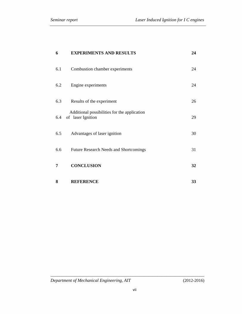
6 EXPERIMENTS AND RESULTS 24
6.1 Combustion chamber experiments 24
6.2 Engine experiments 24
6.3 Results of the experiment 26
6.4Additional possibilities for the application
of laser Ignition 29
6.5 Advantages of laser ignition 30
6.6 Future Research Needs and Shortcomings 31
7 CONCLUSION 32
8 REFERENCE 33
_____________________________________________________________________Department of Mechanical Engineering, AIT (2012-2016)
vii
Seminar report Laser Induced Ignition for I C engines
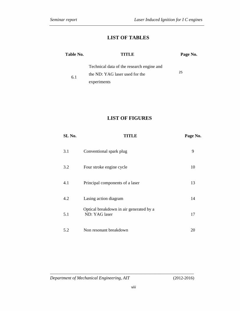
LIST OF TABLES
Table No. TITLE Page No.
6.1
Technical data of the research engine and
the ND: YAG laser used for the
experiments
LIST OF FIGURES
SL No. TITLE Page No.
3.1 Conventional spark plug 9
3.2 Four stroke engine cycle 10
4.1 Principal components of a laser 13
4.2 Lasing action diagram 14
5.1Optical breakdown in air generated by aND: YAG laser 17
5.2 Non resonant breakdown 20
_________________________________________________________________Department of Mechanical Engineering, AIT (2012-2016)
viii
25
Seminar report Laser Induced Ignition for I C engines
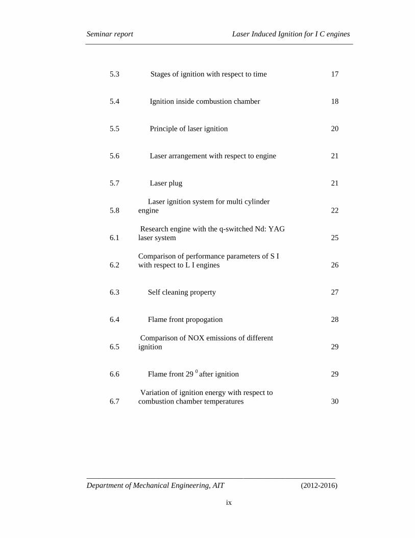
5.3 Stages of ignition with respect to time 17
5.4 Ignition inside combustion chamber 18
5.5 Principle of laser ignition 20
5.6 Laser arrangement with respect to engine 21
5.7 Laser plug 21
5.8Laser ignition system for multi cylinder
engine 22
6.1Research engine with the q-switched Nd: YAG
laser system 25
6.2Comparison of performance parameters of S Iwith respect to L I engines 26
6.3 Self cleaning property 27
6.4 Flame front propogation 28
6.5Comparison of NOX emissions of different
ignition 29
6.6 Flame front 29 0 after ignition 29
6.7Variation of ignition energy with respect to
combustion chamber temperatures 30
_________________________________________________________________Department of Mechanical Engineering, AIT (2012-2016)
ix
Seminar report Laser Induced Ignition for I C engines
LIST OF SYMBOLS
I Intensity of an electromagnetic wave
E Electric field strength
D Diameter of the laser beam
M Beam quality
λ Wave length of laser beam
f Focal length of the optical element
T Temperature
P Pressure
k Boltzmann’s constant
_________________________________________________________________Department of Mechanical Engineering, AIT (2012-2016)
x
Seminar report Laser Induced Ignition for I C engines
LIST OF ABBREVIATIONS
IMEP Indicated Mean Effective Pressures
COV Coefficient Of Variation
SIS Spark Ignition System
LIS Laser Ignition System
IC Engine Internal Combustion Engine
µs Nano Second
Mj Milli-Joule
Mpa Mega Pascal
MPI Multi Photon Ionization
DOHC Double-Overhead-Camshaft
_____________________________________________________________________Department of Mechanical Engineering, AIT (2012-2016)
Xi
Seminar report Laser Induced Ignition for I C engines
PPM Particles Per Million
CH4 Methane
CO2 Carbon Dioxide
NO X Oxides Of Nitrogen
MEP Mean Effective Pressure
Is Build-Up Intensity
Es Build-Up Energy
MPE Minimum Pulse Energy For Ignition
_____________________________________________________________Department of Mechanical Engineering, AIT (2012-2016)
Xii
Seminar report Laser Induced Ignition for I C engines
Department of Mechanical Engineering, AIT (2012-2016)1
CHAPTER - 1
INTRODUCTION
It's widely accepted that the internal combustion engines will continue to power our vehicles.
Hence, as the global mobilization of people and goods increases, advances in combustion and
after-treatment are needed to reduce the environmental impact of the continued use of IC
engine vehicles. To meet environmental legislation requirements, automotive manufacturers
continue to address two critical aspects of engine performance, fuel economy and exhaust gas
emissions. New engines are becoming increasingly complex, with advanced combustion
mechanisms that burn an increasing variety of fuels to meet future goals on performance, fuel
economy and emissions. The spark plug has remained largely unchanged since its invention,
yet its poor ability to ignite highly dilute air- fuel mixtures limits the potential for improving
combustion efficiency. Spark ignition (SI) also restricts engine design, particularly in new
engines, since the spark position is fixed by the cylinder head location of the plug, and the
protruding electrode disturbs the cylinder geometry and may quench the combustion flame
kernel.
So, many alternatives are being sought after to counter these limitations. One of the
alternative is the laser ignition system (LIS) being described here. Compared to a
conventional spark plug, a LIS should be a favorable ignition source in terms of lean burn
characteristics and system flexibility . So, in this paper we'll be discussing the implementation
and impact of LIS on IC engines.
Seminar report Laser Induced Ignition for I C engines
Department of Mechanical Engineering, AIT (2012-2016)2
CHAPTER 2
LITREATURE REVIEW
The history of laser induced ignition has progressed in three distinct directions. The first is the
theoretical analysis of the breakdown phenomenon in which the physical ignition processes at
the molecular level of the ignition event are investigated. The second is comprised of
laboratory experiments conducted to gain insight and understanding of the ignition process
and to help test and tune previously developed theories. The third consists of experiments and
analysis performed on slider-crank piston engines to gauge the effectiveness of laser energy
ignition on the engine operating parameters.
Past theoretical studies have lead to the statistical development and comparison of ignition
delay and ignition probability models to experimental observations allowing the direct
correlation of gas (usually methane) concentration to ignitability and ignition delay.
Theoretical analysis has also led to the development of shock wave heating models, which aid
in the explanation of the propagation of hot expanding gas, produced by the laser spark, that
perpetuates the combustion process. Further theoretical examinations and the availability of
experimental data have allowed researchers to develop more precise estimations of the
minimum required laser induced breakdown energy required for ignition of combustible gases
as well as focal length effects.
The method by which the laser induces breakdown in a combustible gaseous mixture has
been divided into four basic processes: thermal heating, non resonant breakdown,
resonant breakdown and photochemical excitation. Thermal heating takes place where the
laser beam is incident on a solid target and induces excitation by heating the target or by
exciting a rotational or vibrational modes of oscillation in the surrounding gas.
Resonant breakdown occurs when the incident radiation ionizes the gas molecules and frees
up electrons to absorb the radiation energy and in turn ionize other gas molecules leading to
avalanche breakdown. Photochemical ignition occurs when a single photon dissociates a
molecule thus allowing the ionized constituents to react with the surrounding gases. Non-
resonant breakdown occurs when laser light is focused into a gas and the electrical field
component of the light is strong enough to initiate the electrical breakdown of the gas. The
non-resonant breakdown mechanism is the predominant factor governing the results presented
in this work.
Seminar report Laser Induced Ignition for I C engines
Department of Mechanical Engineering, AIT (2012-2016)3
Lasers promise less pollution and greater fuel efficiency, but making small, powerful lasers
has, until now, proven hard. To ignite combustion, a laser must focus light to approximately
100 giga-watts per square centimeter with short pulses of more than 10 millijoules each.In the
past, lasers that could meet those requirements were limited to basic research because they
were big, inefficient, and unstable. Nor could they be located away from the engine, because
their powerful beams would destroy any optical fibers that delivered light to the cylinders.
This problem overcame by making composite lasers from ceramic powders. In this the
powders is heated and fuse into optically transparent solids and embeds metal ions in them to
tune their properties. Ceramics are easier to tune optically than conventional crystals. They
are also much stronger, more durable, and thermally conductive, so they can dissipate the heat
from an engine without breaking down. The use of laser ignition to improve gas engine
performance was initially demonstrated by J. D. Dale in 1978. However, with very few exceptions,
work in this area has for the last 20 years been limited to laboratory experimentation employing large,
expensive and relatively complicated lasers and laser beam delivery systems.
Experimental studies have been vital to extending the value of the theoretical
examinations and in gaining a further understanding of the combustion process. Combustion
vessel and open flame jet experimentation with methane (CH4) and other combustible gases
have proven invaluable in the search for better fuel economy and emissions and provide a
better understanding of the general ignition and combustion processes. Results of the laser
spark combustion vessel studies has indicated a shortened ignition delay and higher peak
pressures than an electrical spark ignited combustion event. Some studies investigated the
ignition energy effect on the combustion process and found that for stoichiometric conditions
the amount of energy had only a slight pressure dependence, however more energy was
required for breakdown as the equivalence ratio approached either lean or rich conditions
Other studies have examined multi- point laser ignition as a means of gaining quicker
combustion which allows for higher thermal efficiency due to reduced time for thermal losses
during the combustion event and overall shorter travel distances for the flames .The most
promising result of the combustion vessel examination of laser ignition is the ability of the
optical energy to ignite and more readily burn lean mixtures. This offers the potential for
extending the lean limit in spark ignited engines which .Laser ignition studies performed on
internal combustion engines have allowed researchers to directly study the effect that laser
Seminar report Laser Induced Ignition for I C engines
Department of Mechanical Engineering, AIT (2012-2016)4
induced ignition has on the operating and emissions characteristics of an operating engine.
Past and recent studies have indicated a higher and quicker combustion pressure rise with
laser ignition.
The experimentation performed by Dale et al., used a gasoline-fueled stoichiometric
operating internal combustion engine for testing. The research performed by Ma et al.,
involved a motored slider crank mechanism that was not self sustaining.
Researchers from Japan's National Institutes of Natural Sciences (NINS) are creating
laser igniters that could one day replace spark plugs in automobile engines. The team from
Japan built its laser from two yttrium aluminum- gallium (YAG) segments, one doped with
neodymium, the other with chromium. They bonded the two sections together to form a
powerful laser only 9 millimeters in diameter and 11 millimeters long (a bit less than half an
inch). The composite generates two laser beams that can ignite fuel in two separate locations
at the same time. This would produce a flame wall that grows faster and more uniformly than
one lit by a single laser. The laser is not strong enough to light the leanest fuel mixtures with a
single pulse. By using several 800- picosecond-long pulses, however, they can inject enough
energy to ignite the mixture completely.A commercial automotive engine will require 60 Hz
(or pulse trains per second), The team has already tested the new dual-beam laser at 100 Hz.
The team is also at work on a three-beam laser that will enable even faster and more uniform
combustion. The laser-ignition system, although highly promising, is not yet being installed
into actual automobiles made in a factory. Scientist team from Japan is, however, working
with a large spark-plug company and with DENSO Corporation, a member of the Toyota
Group.
Seminar report Laser Induced Ignition for I C engines
Department of Mechanical Engineering, AIT (2012-2016)5
CHAPTER 3
BACKGROUND STUDY OF IGNITION IN IC ENGINE
3.1 What is ignition
Ignition is the process of starting radical reactions until a self-sustaining flame has developed.
One can distinguish between auto ignition, induced ignition and photo-ignition, the latter
being caused by photolytic generation of radicals
3.2 Ignition types
3.2.1 Compression Ignition (CI) or Auto Ignition
At certain values of temperature and pressure a mixture will ignite spontaneously, this is
known as the auto ignition or compression ignition
3.2.2 Induced Ignition
A process where a mixture, which would not ignite by it, is ignited locally by an ignition
source (i.e. Electric spark plug, pulsed laser, microwave ignition source) is called induced
ignition. In induced ignition, energy is deposited, leading to a temperature rise in a small
volume of the mixture, where auto ignition takes place or the energy is used for the generation
of radicals. In both cases subsequent flame propagation occurs and sets the mixture on fire.
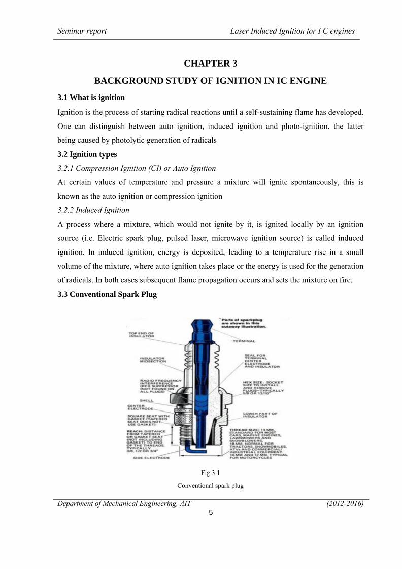
3.3 Conventional Spark Plug
Fig.3.1
Conventional spark plug
Seminar report Laser Induced Ignition for I C engines
Department of Mechanical Engineering, AIT (2012-2016)6
A spark plug (sometimes, in British English, a sparking plug, and, colloquially, a plug) is a
device for delivering electric current from an ignition system to the combustion chamber of
a spark-ignition engine to ignite the compressed fuel/air mixture by an electric spark, while
containing combustion pressure within the engine. A spark plug has a metal threaded shell,
electrically isolated from a central electrode by a porcelain insulator. The central electrode,
which may contain a resistor, is connected by a heavily insulated wire to the output terminal
of an ignition coil or magneto. The spark plug's metal shell is screwed into the
engine's cylinder head and thus electrically grounded. The central electrode protrudes through
the porcelain insulator into the combustion chamber, forming one or more spark gaps between
the inner end of the central electrode and usually one or more protuberances or structures
attached to the inner end of the threaded shell and designated the side, earth,
or ground electrode(s).
Spark plugs may also be used for other purposes; in Saab Direct Ignition when they
are not firing, spark plugs are used to measure ionization in the cylinders – this ionic current
measurement is used to replace the ordinary cam phase sensor, knock sensor and misfire
measurement function. Spark plugs may also be used in other applications such
as furnaces wherein a combustible fuel/air mixture must be ignited. In this case, they are
sometimes referred to as flame igniters
3.4 Sparking Plug Ignition
Conventional spark plug ignition has been used for many years. For ignition of a fuel-air
mixture the fuel-air mixture is compressed and at the right moment a high voltage is applied
to the electrodes of the spark plug.
When the ignition switch is turned on current flows from the battery to the
ignition coil. Current flows through the Primary winding of the ignition coil where one end is
connected to the contact breaker. A cam which is directly connected to the camshaft opens
and closes the contact breaker (CB) points according to the number of the cylinders. When the
cam lobe Pushes CB switch, the CB point opens which causes the current from the primary
circuit to break. Due to a break in the current, an EMF is induced in the second winding
having more number of turns than the primary which increases the battery 12 volts to 22,000
volts.
Seminar report Laser Induced Ignition for I C engines
Department of Mechanical Engineering, AIT (2012-2016)7
The high voltage produced by the secondary winding is then transferred to the
distributor. Higher voltage is then transferred to the spark plug terminal via a high tension
cable. A voltage difference is generated between the central electrode and ground electrode of
the spark plug. The voltage is continuously transferred through the central electrode (which is
sealed using an insulator). When the voltage exceeds the dielectric of strength of the gases
between the electrodes, the gases are ionized. Due to the ionization of gases, they become
conductors and allow the current to flow through the gap and the spark is finally produced.
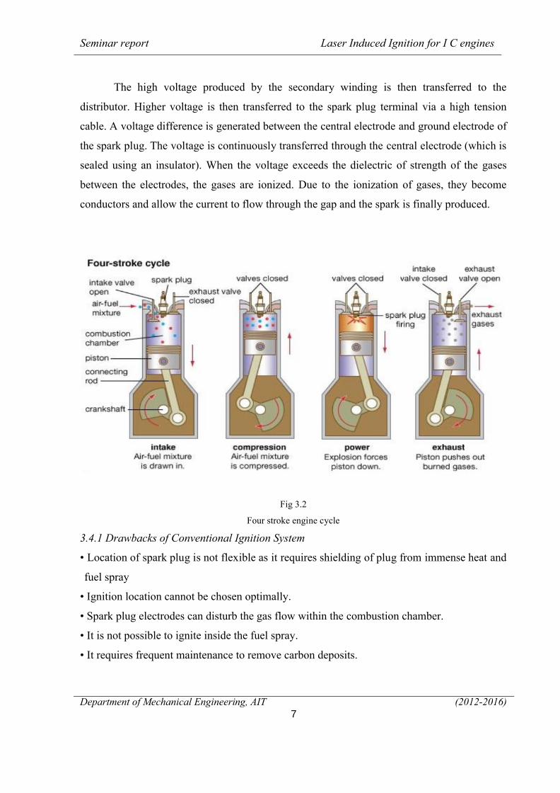
Fig 3.2
Four stroke engine cycle
3.4.1 Drawbacks of Conventional Ignition System
• Location of spark plug is not flexible as it requires shielding of plug from immense heat and
fuel spray
• Ignition location cannot be chosen optimally.
• Spark plug electrodes can disturb the gas flow within the combustion chamber.
• It is not possible to ignite inside the fuel spray.
• It requires frequent maintenance to remove carbon deposits.
Seminar report Laser Induced Ignition for I C engines
Department of Mechanical Engineering, AIT (2012-2016)8
• Leaner mixtures cannot be burned, ratio between fuel and air has to be within the correct
range
• Degradation of electrodes at high pressure and temperature.
• Flame propagation is slow.
• Multi point fuel ignition is not feasible.
• Higher turbulence levels are required.
• Erosion of spark plug electrodes.
Seminar report Laser Induced Ignition for I C engines
Department of Mechanical Engineering, AIT (2012-2016)9
CHAPTER - 4
LASER
The word LASER is an acronym. It stands for Light Amplification by the Stimulated
Emission of Radiation. By "radiation", however, the acronym refers to a radiant vibration, not
an emission of radioactive particles. In other words, the emissions of lasers are in the form of
light, and the frequencies can range anywhere from infra-red to ultraviolet. Those lasers of
interest to the laser display industry, however, are mostly those whose output is visible (from
red to deep blue).
As the acronym suggests, lasers work through a process called stimulated emission.
The lasers we typically employ are called ion gas lasers, due to the fact that they utilize a gas
or a mixture of gases as the lasing medium. These work because certain gases are "easily"
coerced to produce visible light through this process.
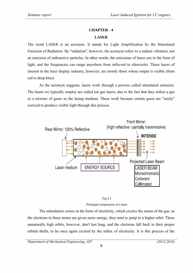
Fig 4.1
Principal components of a laser
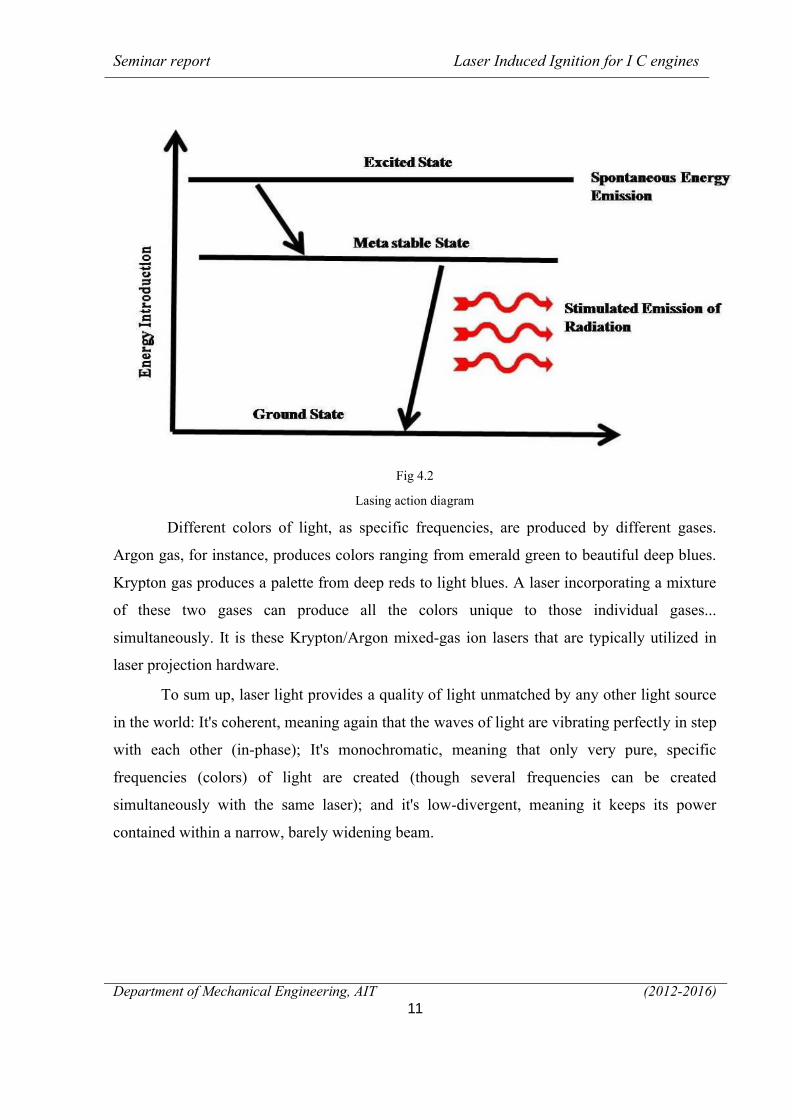
The stimulation comes in the form of electricity, which excites the atoms of the gas: as
the electrons in these atoms are given more energy, they tend to jump to a higher orbit. These
unnaturally high orbits, however, don't last long, and the electrons fall back to their proper
orbital shells, to be once again excited by the influx of electricity. It is this process of the
Seminar report Laser Induced Ignition for I C engines
Department of Mechanical Engineering, AIT (2012-2016)10
electrons returning to their original orbits that creates the laser light we see (actually, it's more
appropriate to call it a jump, for an electron falls from orbit in a span of time infinitesimally
small): During this jump back down, the extra energy is released from each atom as a packet
called a photon (light). Moreover, if this photon collides with another already excited atom,
that atom is also stimulated to emit a photon...but this new photon will be vibrating perfectly
in step (in-phase) with the colliding photon, and will be traveling on the exact same course.
Photons are released, however, in haphazard directions. In order to get them aligned into the
tight beam of light with which we're familiar, the tubes in which the atoms of gas are excited
must be mirrored on both ends. Any photon that now happens to randomly travel exactly
perpendicular with the mirrors on both ends (which inevitably happens) will cause a
remarkable chain of events: The drama begins with the photon's 'cloning' when it bounces off
the mirror and collides with another excited atom. Those two in-phase photons then collide
with two more excited atoms, making four photons traveling in-phase, and exactly down the
length of the laser tube. This process is then repeated in a geometric progression of photons
parading exactly down the laser tube, colliding with more excited atoms, creating more
photons, reflecting off the mirrors, and repeating and amplifying the process over and over
again. The laser light we see is finally released through the front mirror, whose reflective
coating was designed to be partially transparent. In this way, a small percentage of those
perfectly aligned photons is allowed to escape, forming the thin, straight, coherent, and
beautiful beams we call LASER light.
Seminar report Laser Induced Ignition for I C engines
Department of Mechanical Engineering, AIT (2012-2016)11
Fig 4.2
Lasing action diagram
Different colors of light, as specific frequencies, are produced by different gases.
Argon gas, for instance, produces colors ranging from emerald green to beautiful deep blues.
Krypton gas produces a palette from deep reds to light blues. A laser incorporating a mixture
of these two gases can produce all the colors unique to those individual gases...
simultaneously. It is these Krypton/Argon mixed-gas ion lasers that are typically utilized in
laser projection hardware.
To sum up, laser light provides a quality of light unmatched by any other light source
in the world: It's coherent, meaning again that the waves of light are vibrating perfectly in step
with each other (in-phase); It's monochromatic, meaning that only very pure, specific
frequencies (colors) of light are created (though several frequencies can be created
simultaneously with the same laser); and it's low-divergent, meaning it keeps its power
contained within a narrow, barely widening beam.
Seminar report Laser Induced Ignition for I C engines
Department of Mechanical Engineering, AIT (2012-2016)12
4.1 Types of laser
∑ Gas lasers
The helium-neon laser (hene) emits 543 nm and 633 nm and is very common in education
because of its low cost. Carbon dioxide lasers emit up to 100 kw at 9.6 μm and10.6 μm, and
are used in industry for cutting and welding. Argon-ion lasers emit 458 nm, 488 nm or 514.5
nm. Carbon monoxide lasers must be cooled but can produce up to 500kw. The transverse
electrical discharge in gas at atmospheric pressure (tea) laser is an inexpensive gas laser
producing uv light at 337.1 nm. Metal ion lasers are gas lasers that generate deep ultraviolet
wavelengths. Helium-silver (heag) 224 nm and neon-copper (necu) 248 nm are two examples.
These lasers have particularly narrow oscillation line widths of less than 3 ghz (0.5 pico
meters) making them candidates for use in fluorescence suppressed raman spectroscopy.
∑ Chemical laser
Chemical lasers are powered by a chemical reaction, and can achieve high powers in
continuous operation. For example, in the hydrogen fluoride laser (2700-2900 nm) and the
deuterium fluoride laser (3800 nm) the reaction is the combination of hydrogen or deuterium
gas with combustion products of ethylene in nitrogen trifluoride.
∑ Excimer lasers
Excimer lasers produce ultraviolet light, and are used in semiconductor manufacturing and in
lasik eye surgery. Commonly used excimer molecules include f2 (emitting at 157 nm), arf
(193 nm), krcl (222 nm), krf (248 nm), xecl (308 nm), and xef (351nm).
Solid-state lasers
Solid state laser materials are commonly made by doping a crystalline solid host with ions
that provide the required energy states. For example, the first working laser was made from
ruby, or chromium-doped sapphire. Another common type is made from neodymium-doped
yttrium aluminium garnet (yag), known as nd:yag. Nd:yag lasers can produce high powers in
the infrared spectrum at 1064 nm. They are used for cutting, welding and marking of metals
and other materials, and also in spectroscopy and for pumping dye lasers. Nd:yag lasers are
also commonly doubled their frequency to produce 532 nm when a visible (green) coherent
source is required. ytterbium, holmium, thulium and erbium are other common dopants in
solid state lasers. The ho-yag is usually operated in a pulsed mode, and passed through optical
Seminar report Laser Induced Ignition for I C engines
Department of Mechanical Engineering, AIT (2012-2016)13
fibre surgical devices to resurface joints, remove rot from teeth, vaporize cancers, and
pulverize kidney and gall stones. Titanium-doped sapphire (ti: sapphire) produces a highly
tunable infrared laser, used for spectroscopy. Solid state lasers also include glass or optical
fibre hosted lasers, for example, with erbium or ytterbium ions as the active species. These
allow extremely long gain regions, and can support very high output powers because the
fibre’s high surface area to volume ratio allows efficient cooling and its wave guiding
properties reduce thermal distortion of the beam.
∑ Semiconductor lasers
Laser diodes produce wavelengths from 405 nm to 1550 nm. Low power laser diodes are used
in laser pointers, laser printers, and cd/dvd players. More powerful laser diodes are frequently
used to optically pump other lasers with high efficiency. The highest power industrial laser
diodes, with power up to 10 kw, are used in industry for cutting and welding. External-cavity
semiconductor lasers have a semiconductor active medium in a larger cavity. These devices
can generate high power outputs with good beam quality, wavelength-tunable narrow-line
width radiation, or ultra-short laser pulses.
Vertical cavity surface-emitting lasers (vessels) are semiconductor lasers whose
emission direction is perpendicular to the surface of the wafer. Vessel devices typically have a
more circular output beam than conventional laser diodes, and potentially could be much
cheaper to manufacture. As of 2005, only 850 nm vessels are widely available, with 1300 nm
vessels beginning to be commercialized [7], and 1550 nm devices an area of research. Vessels
are external-cavity vessels. Quantum cascade lasers are semiconductor lasers that have an
active transition between energy sub-bands of an electron in a structure containing several
quantum wells
∑ Dye lasers
Dye lasers use an organic dye as the gain medium. The wide gain spectrum of available dyes
allows these lasers to be highly tunable, or to produce very short-duration pulses (on the order
of a few femto seconds).
Seminar report Laser Induced Ignition for I C engines
Department of Mechanical Engineering, AIT (2012-2016)14
CHAPTER 5
LASER IGNITION
Laser ignition, or laser-induced ignition, is the process of starting combustion by the stimulus
of a laser light source.Laser ignition uses an optical breakdown of gas molecule caused by an
intense laser pulse to ignite gas mixtures. The beam of a powerful short pulse laser is focused
by a lens into a combustion chamber and near the focal spot and hot and bright plasma is
generated.
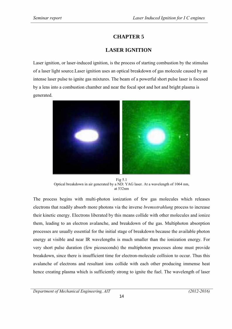
Fig 5.1Optical breakdown in air generated by a ND: YAG laser. At a wavelength of 1064 nm,
at 532nm
The process begins with multi-photon ionization of few gas molecules which releases
electrons that readily absorb more photons via the inverse bremsstrahlung process to increase
their kinetic energy. Electrons liberated by this means collide with other molecules and ionize
them, leading to an electron avalanche, and breakdown of the gas. Multiphoton absorption
processes are usually essential for the initial stage of breakdown because the available photon
energy at visible and near IR wavelengths is much smaller than the ionization energy. For
very short pulse duration (few picoseconds) the multiphoton processes alone must provide
breakdown, since there is insufficient time for electron-molecule collision to occur. Thus this
avalanche of electrons and resultant ions collide with each other producing immense heat
hence creating plasma which is sufficiently strong to ignite the fuel. The wavelength of laser
Seminar report Laser Induced Ignition for I C engines
Department of Mechanical Engineering, AIT (2012-2016)15
depend upon the absorption properties of the laser and the minimum energy required depends
upon the number of photons required for producing the electron avalanche.
5.1 Types of laser ignition
Basically, energetic interactions of a laser with a gas may be classified into one of the
following four schemes as described in.
∑ Thermal initiation
In thermal initiation of ignition, there is no electrical breakdown of the gas and a laser beam is
used to raise the kinetic energy of target molecules in translational, rotational, or vibrational
forms. Consequently, molecular bonds are broken and chemical reaction occur leading to
ignition with typically long ignition delay times. This method is suitable for fuel/oxidizer
mixtures with strong absorption at the laser wavelength. However, if in a gaseous or liquid
mixtures is an objective, thermal ignition is unlikely a preferred choice due to energy
absorption along the laser propagation direction. Conversely, this is an ideal method for
homogeneous or distributed ignition of combustible gases or liquids. Thermal ignition method
has been used successfully for solid fuels due to their absorption ability at infrared
wavelengths.
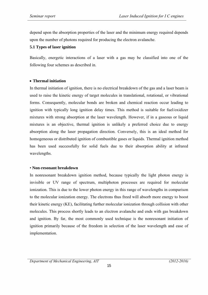
• Non-resonant breakdown
In nonresonant breakdown ignition method, because typically the light photon energy is
invisible or UV range of spectrum, multiphoton processes are required for molecular
ionization. This is due to the lower photon energy in this range of wavelengths in comparison
to the molecular ionization energy. The electrons thus freed will absorb more energy to boost
their kinetic energy (KE), facilitating further molecular ionization through collision with other
molecules. This process shortly leads to an electron avalanche and ends with gas breakdown
and ignition. By far, the most commonly used technique is the nonresonant initiation of
ignition primarily because of the freedom in selection of the laser wavelength and ease of
implementation.
Seminar report Laser Induced Ignition for I C engines
Department of Mechanical Engineering, AIT (2012-2016)16
Fig 5.2
Non resonant breakdown
• Resonant breakdown
The resonant breakdown laser ignition process involves, first, a nonresonant multiphoton
dissociation of molecules resulting to freed atoms, followed by a resonant photo ionization of
these atoms. This process generates sufficient electrons needed for gas breakdown.
Theoretically, less input energy is required due to the resonant nature of this method.
• Photochemical mechanisms
In photochemical ignition approach, very little direct heating takes place and the laser beam
brings about molecular dissociation leading to formation of radicals (i.e., highly reactive
chemical species), if the production rate of the radicals produced by this approach is higher
than the recombination rate (i.e., neutralizing the radicals), then the number of these highly
active species will reach a threshold value, leading to an ignition event. This (radical) number
augmentation scenario is named as chain-branching in chemical terms.
Seminar report Laser Induced Ignition for I C engines
Department of Mechanical Engineering, AIT (2012-2016)17
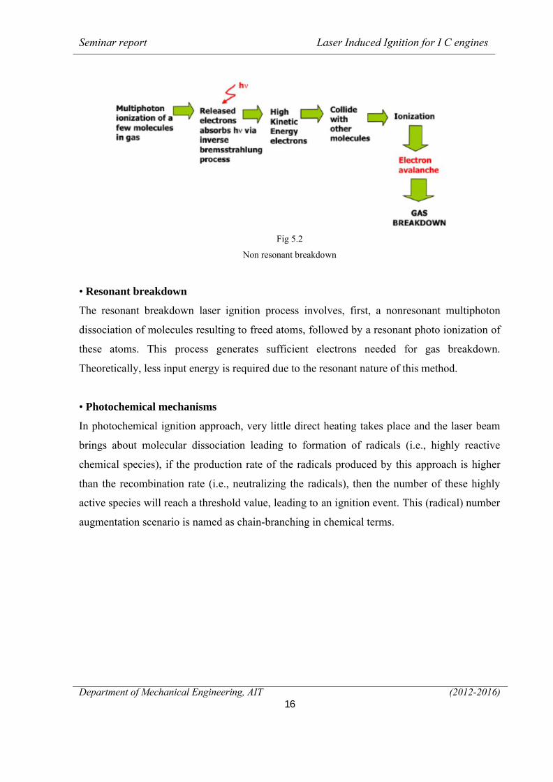
5.2 Laser ignition along time
Laser ignition encompasses the nanosecond domain of the laser pulse itself to the duration of
the entire combustion lasting several hundreds of milliseconds.
Fig 5.3
Stages of ignition with respect to time
The laser energy is deposited in a few nanoseconds which lead to a shock wave generation. In
the first milliseconds an ignition delay can be observed which has duration between 5 – 100
ms depending on the mixture. Combustion can last between 100 ms up to several seconds
again depending on the gas mixture, initial pressure, pulse energy, plasma size, position of the
plasma in the combustion bomb and initial temperature
Seminar report Laser Induced Ignition for I C engines
Department of Mechanical Engineering, AIT (2012-2016)18
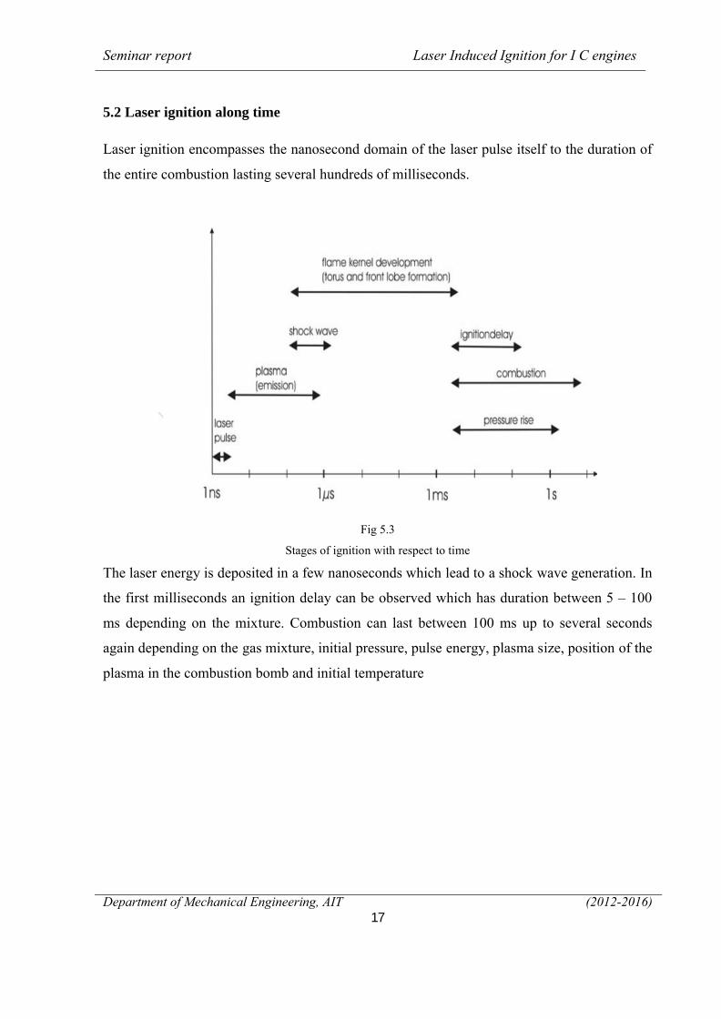
5.3 Ignition in combustion chamber
Fig 5.4
Ignition inside combustion chamber
The laser beam is passed through a convex lens, this convex lens diverge the beam and make
it immensely strong and sufficient enough to start combustion at that point. Hence the fuel is
ignited, at the focal point. The focal point is adjusted where the ignition is required to have.
5.4 Mechanism of laser ignition
It is well know that short and intensive laser pulses are able to produce an “optical
breakdown” in air. Necessary intensities are in the range between 1010 to 1011W/cm2. At such
intensities, gas molecules are dissociated and ionized within the vicinity of the focal spot of a
laser beam and hot plasma is generated. This plasma is heated by the incoming laser beam and
a strong shock wave occurs. The expanding hot plasma can be used for the ignition of fuel-gas
mixtures. By comparing the field strength of the field between the electrodes of a spark plug
and the field of a laser pulse it should be possible to estimate the required laser intensity for
generation of an optical breakdown. The field strength reaches values in the range of
approximately 3×10⁴V/cm between the electrodes of a conventional spark plug. Since the
intensity of an electromagnetic wave is proportional to the square of the electric field strength
I ∝E2, one can estimate that the intensity should be in the order of 2 × 10⁶ W/cm2, which is
several orders of magnitude lower as indicated by experiments on laser ignition. The reason is
that usually no free electrons are available within the irradiated volume. At the electrodes of a
spark plug electrons can be liberated by field emission processes. In contrary, ionization due
to irradiation requires a “multiphoton” process where several photons hit the atom at nearly
Seminar report Laser Induced Ignition for I C engines
Department of Mechanical Engineering, AIT ( 2012-2016 )19
the same time. Such multiphoton ionization processes can only happen at very high irradiation
levels (in the order of 1010to 1011W/cm2)
where the number of photons is extremely high. For example, nitrogen has an ionization
energy of approximately 14.5 eV, whereas one photon emitted by a Nd:YAG laser has
an energy of 1.1 eV, thus more than 13 photons are required for ionization of nitrogen.
The pulse energy of a laser system for ignition can be estimated by the following
calculation. The diameter d of a focused laser beam is
D = 2 × wf = 2 × M2 × ………. (1)
where M2 is the beam quality, F is the focal length of the optical element and D is the
diameter of the laser beam with the wavelength λ. Now it is assumed that the laser beam
irradiates a spherical volume.
V =^ …………………….(2)
From the thermodynamical gas equation the number of particles N in a volume V is
N = ……………………..(3)
With the pressure p, temperature T and Boltzmann’s constant k = 1.38 × 10 -23J/K. Inside the
irradiated volume, N molecules have to be dissociated where first the dissociation energy Wd
is required and finally 2N atoms are ionized (ionization energy Wi). Using known values for
Wd= 9.79 eV and Wi= 14.53 eV for nitrogen, the energy for dissociating and ionizing all
particles inside the volume can be calculated as
W = ( ) × (Wd + 2Wi) ……(4)
For a spot radius of about 100 μm the equation gives a maximum energy of approximately 1
mJ.Since not all particles inside the irradiated volume have to be ionized, even
smallerenergies should be sufficient for generation of an optical breakdown.
It is assumed that the intensity which is necessary for the generation of an optical breakdown
processes is related to the pressure of the gas
I α 1/Pn
With n =1…5 depending on the mechanism of multiphoton process. Higher pressures, like in
a combustion chamber should ease the ignition process what favors the laser induced ignition.
Seminar report Laser Induced Ignition for I C engines
Department of Mechanical Engineering, AIT (2012-2016)20
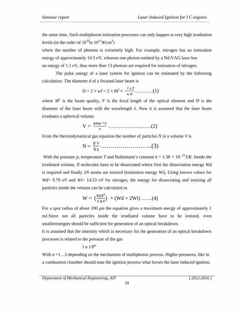
5.5 Principle of laser ignition
Fig 5.5Principle of laser ignition
The laser beam is passed through a convex lens, this convex lens diverge the beam and make
it immensely strong and sufficient enough to start combustion at that point. Hence the fuel is
ignited, at the focal point, with the mechanism shown above. The focal point is adjusted
where the ignition is required to have.
5.6 Arrangement of laser ignition system
A laser ignition device for irradiating and condensing laser beams in a combustion chamber of
an internal combustion engine so as to ignite fuel particles within the combustion chamber,
includes: a laser beam generating unit for emitting the laser beams; and a condensing optical
member for guiding the laser beams into the combustion chamber such that the laser beams
are condensed in the combustion chamber.
Seminar report Laser Induced Ignition for I C engines
Department of Mechanical Engineering, AIT (2012-2016)21
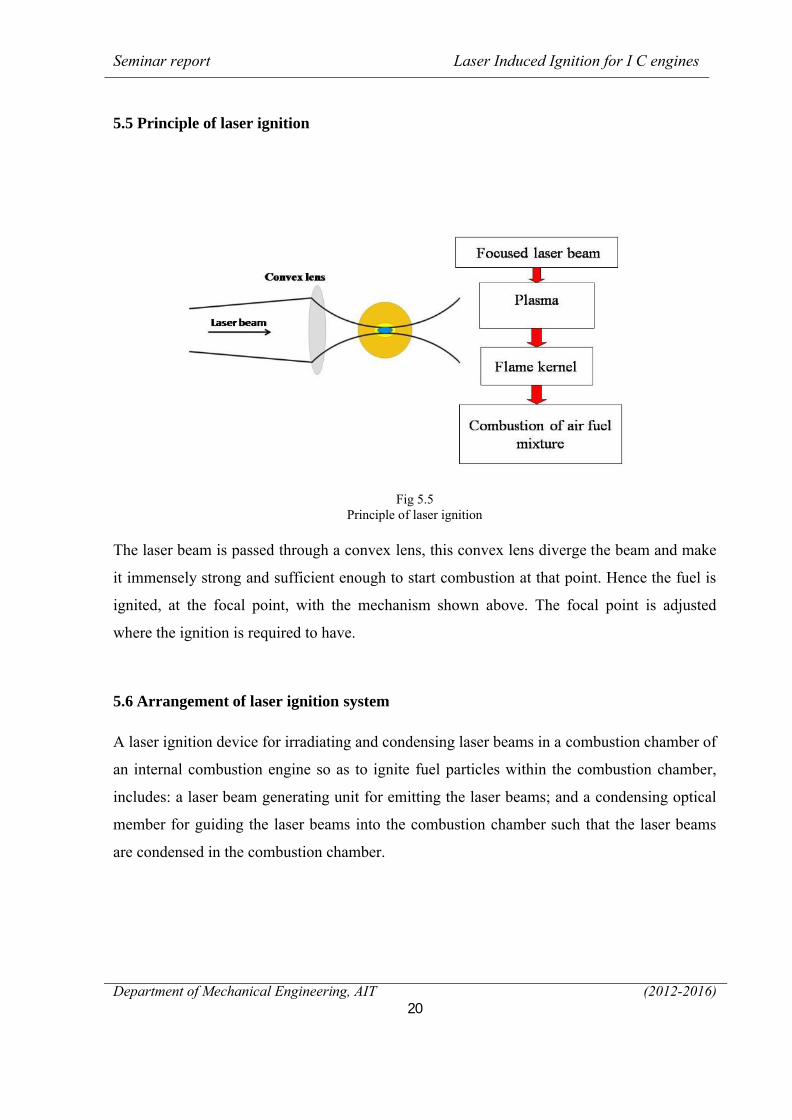
Fig 5.6
Laser arrangement with respect to engine
5.6.1 Laser spark plug
Fig 5.7
Laser plug
Seminar report Laser Induced Ignition for I C engines
Department of Mechanical Engineering, AIT (2012-2016)22
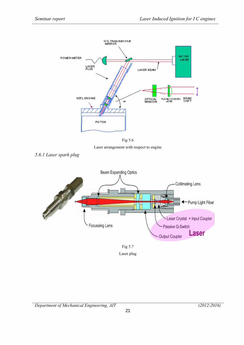
5.7 Working of laser ignition system
Fig 5.8
Laser ignition system for multi cylinder engine
The laser ignition system has a laser transmitter with a fibre-optic cable powered by the car’s
battery. The average power requirements for a laser spark plug are relatively modest. A four
stroke engine operating at maximum of 1200 rpm requires an ignition spark 10 times per
second or 10Hz (1200rpm/2x60). For example 1-Joule/pulse electrical diode pumping levels
we are readily able to generate high mill joule levels of Q-switched energy. This provides us
with an average power requirement for the laser spark plug of say approximately 1-Joule
times 10Hz equal to approximately 10 Watts .It shoots the laser beam to a focusing lens that
would consume a much smaller space than current spark plugs. The lenses focus the beams
into an intense pinpoint of light by passing through an optical window. The laser beam is
passed through a convex lens, this convex lens diverge the beam and make it immensely
strong and sufficient enough to start combustion at that point. Hence the fuel is ignited, at the
focal point, with the mechanism shown above. The focal point is adjusted where the ignition
is required to have. when the fuel is injected into the engine, the laser is fired and produces
enough energy (heat) to ignite the fuel
Hence the fuel is ignited, at the focal point, with the mechanism shown above. The
focal point is adjusted where the ignition is required to have. The plasma generated by the
Seminar report Laser Induced Ignition for I C engines
Department of Mechanical Engineering, AIT (2012-2016)23
Laser beam results in two of the following actions :
1. Emission of high energy photons
2. Generation of shock waves
The high energy photons, heat and ionize the charge present in the path of laser beam which
can be seen from the propagation of the flame which propagates longitudinally along the laser
beam.
The shock waves carry energy out wards from the laser beam and thus help in propagation of
flame
Seminar report Laser Induced Ignition for I C engines
Department of Mechanical Engineering, AIT (2012-2016)24
CHAPTER 6
EXPERIMENTS AND RESULTS
6.1 Combustion chamber experiments
As a feasibility test, an excimer laser has been used for ignition of inflammable gases inside a
combustion bomb. The laser used for the first experiments was a Lambda Physik LPX205,
equipped with an unstable resonator system and operated with KrF, delivering pulses with a
wavelength of 248 nm and a duration of approximately 34 ns with maximum pulse energy of
400 mJ.10 The combustion chamber has had a diameter of 65 mm and a height of 86mm, with
a resulting volume of 290cm3 and was made of steel.
The laser beam was focused into the chamber by means of a lens with a focal length of
50 mm. Variations of pulse energies as well as gas mixtures have been performed to judge the
feasibility of the process. Results indicate that ignition-delay times are smaller and pressure
gradients are much steeper compared to conventional spark plug ignition
6.2 Engine experiments
Since the first feasibility experiments could be concluded successfully, an engine was
modified for laser ignition. The engine has been modified by a replacement of the
conventional spark plug by a window installed into a cylindrical mount. The position of the
focusing lens inside the mount can be changed to allow variations of the location of the initial
optical breakdown. First experiment with laser ignition of the engine have been performed
with an excimer laser, later a q switched ND: YAG has been used
The replacement of the excimer laser was mainly caused by the
fact that especially at very low pulse energies the excimer laser shows strong energy
fluctuations. Pulse energies, ignition location and fuel/air ratios have been varied during the
experiments. The engine has been operated at each setting for several hours, repeatedly. All
laser ignition experiments have been accompanied by conventional spark plug ignition as
reference measurements.
Seminar report Laser Induced Ignition for I C engines
Department of Mechanical Engineering, AIT (2012-2016)25
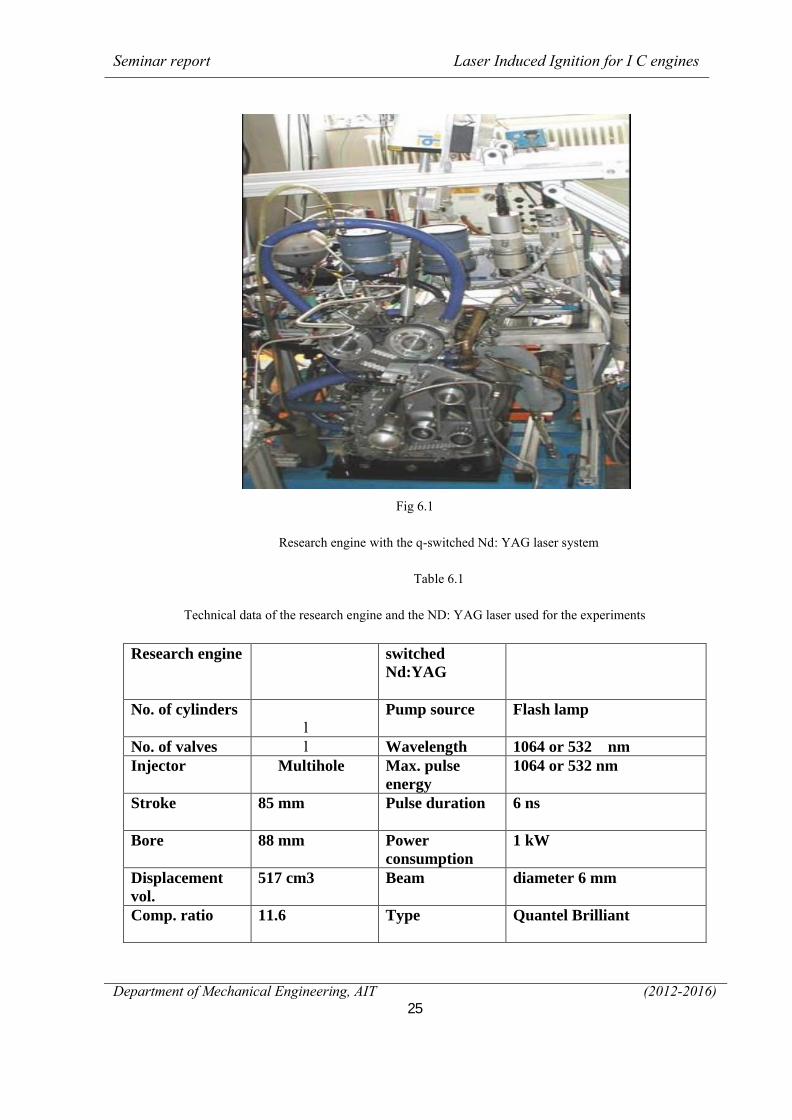
Fig 6.1
Research engine with the q-switched Nd: YAG laser system
Table 6.1
Technical data of the research engine and the ND: YAG laser used for the experiments
Research engine switched Nd:YAG
No. of cylinders1
Pump source Flash lamp
No. of valves 1 Wavelength 1064 or 532 nmInjector Multihole Max. pulse
energy1064 or 532 nm
Stroke 85 mm Pulse duration 6 ns
Bore 88 mm Power consumption
1 kW
Displacement vol.
517 cm3 Beam diameter 6 mm
Comp. ratio 11.6 Type Quantel Brilliant
Seminar report Laser Induced Ignition for I C engines
Department of Mechanical Engineering, AIT (2012-2016)26
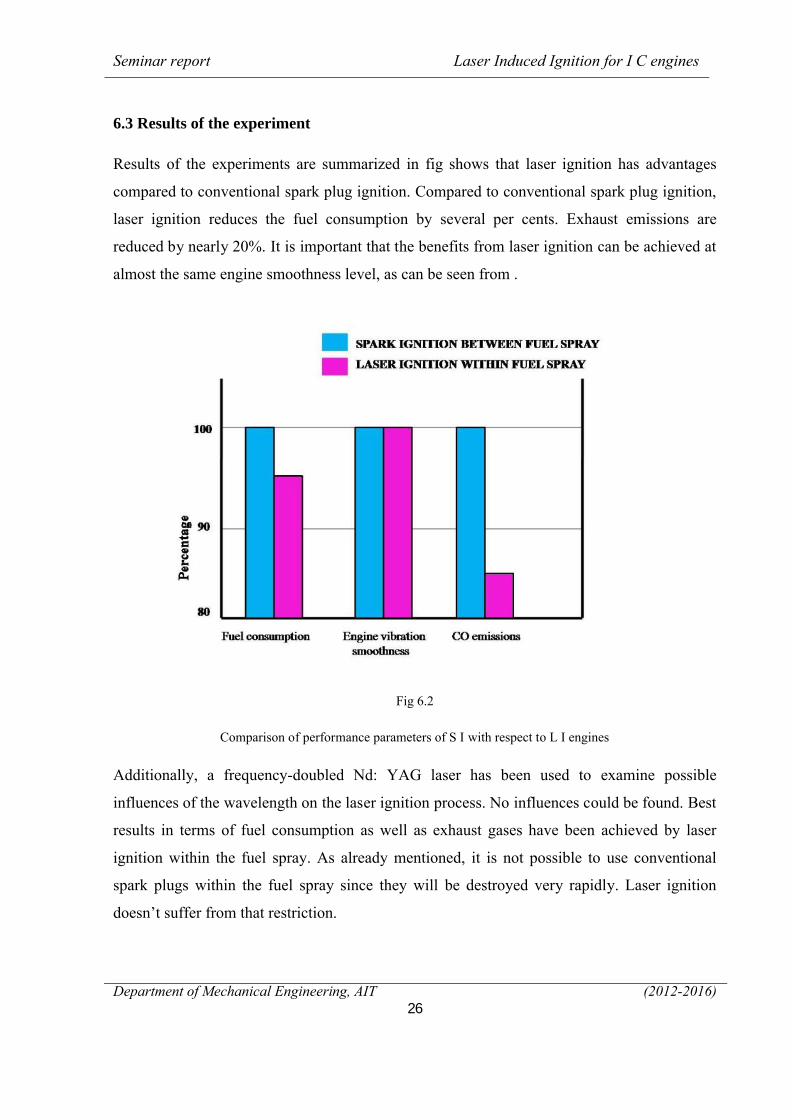
6.3 Results of the experiment
Results of the experiments are summarized in fig shows that laser ignition has advantages
compared to conventional spark plug ignition. Compared to conventional spark plug ignition,
laser ignition reduces the fuel consumption by several per cents. Exhaust emissions are
reduced by nearly 20%. It is important that the benefits from laser ignition can be achieved at
almost the same engine smoothness level, as can be seen from .
Fig 6.2
Comparison of performance parameters of S I with respect to L I engines
Additionally, a frequency-doubled Nd: YAG laser has been used to examine possible
influences of the wavelength on the laser ignition process. No influences could be found. Best
results in terms of fuel consumption as well as exhaust gases have been achieved by laser
ignition within the fuel spray. As already mentioned, it is not possible to use conventional
spark plugs within the fuel spray since they will be destroyed very rapidly. Laser ignition
doesn’t suffer from that restriction.
Seminar report Laser Induced Ignition for I C engines
Department of Mechanical Engineering, AIT (2012-2016)27
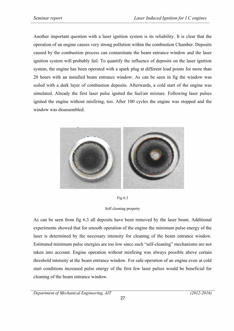
Another important question with a laser ignition system is its reliability. It is clear that the
operation of an engine causes very strong pollution within the combustion Chamber. Deposits
caused by the combustion process can contaminate the beam entrance window and the laser
ignition system will probably fail. To quantify the influence of deposits on the laser ignition
system, the engine has been operated with a spark plug at different load points for more than
20 hours with an installed beam entrance window. As can be seen in fig the window was
soiled with a dark layer of combustion deposits. Afterwards, a cold start of the engine was
simulated. Already the first laser pulse ignited the fuel/air mixture. Following laser pulses
ignited the engine without misfiring, too. After 100 cycles the engine was stopped and the
window was disassembled.
Fig 6.3
Self cleaning property
As can be seen from fig 6.3 all deposits have been removed by the laser beam. Additional
experiments showed that for smooth operation of the engine the minimum pulse energy of the
laser is determined by the necessary intensity for cleaning of the beam entrance window.
Estimated minimum pulse energies are too low since such “self-cleaning” mechanisms are not
taken into account. Engine operation without misfiring was always possible above certain
threshold intensity at the beam entrance window. For safe operation of an engine even at cold
start conditions increased pulse energy of the first few laser pulses would be beneficial for
cleaning of the beam entrance window.
Seminar report Laser Induced Ignition for I C engines
Department of Mechanical Engineering, AIT (2012-2016)28
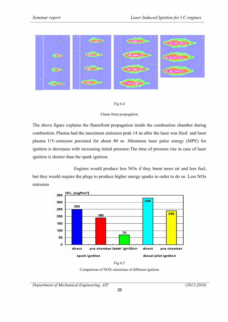
Fig 6.4
Flame front propogation
The above figure explains the flamefront propagation inside the combustion chamber during
combustion .Plasma had the maximum emission peak 14 ns after the laser was fired and laser
plasma UV-emission persisted for about 80 ns .Minimum laser pulse energy (MPE) for
ignition is decreases with increasing initial pressure.The time of pressure rise in case of laser
ignition is shorter than the spark ignition.
Engines would produce less NOx if they burnt more air and less fuel,
but they would require the plugs to produce higher energy sparks in order to do so. Less NOx
emission
Fig 6.5
Comparison of NOX emissions of different ignition
Seminar report Laser Induced Ignition for I C engines
Department of Mechanical Engineering, AIT (2012-2016)29
6.4 Additional possibilities for the application of laser Ignition
To fully utilize the potentialities of laser ignition, the developer must understand and master
the interrelationships in the engine perfectly. There is no sense in utilizing only the NOX
advantages with a costly system and not paying attention to the specific fuel consumption.
Consequently, additional measures must be taken to maintain the fuel consumption level
under conditions of extremely lean operation and even to improve it. In this regard,
researchers place great emphasis on its experience with high turbulence to accelerate
combustion (HEC concept). However, there are also other innovative approaches possible
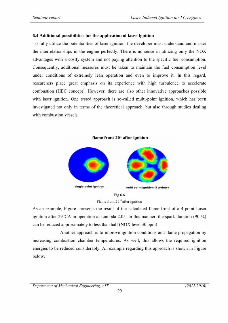
with laser ignition. One tested approach is so-called multi-point ignition, which has been
investigated not only in terms of the theoretical approach, but also through studies dealing
with combustion vessels.
Fig 6.6
Flame front 29 0 after ignition
As an example, Figure presents the result of the calculated flame front of a 4-point Laser
ignition after 29°CA in operation at Lambda 2.05. In this manner, the spark duration (90 %)
can be reduced approximately to less than half (NOX level 30 ppm)
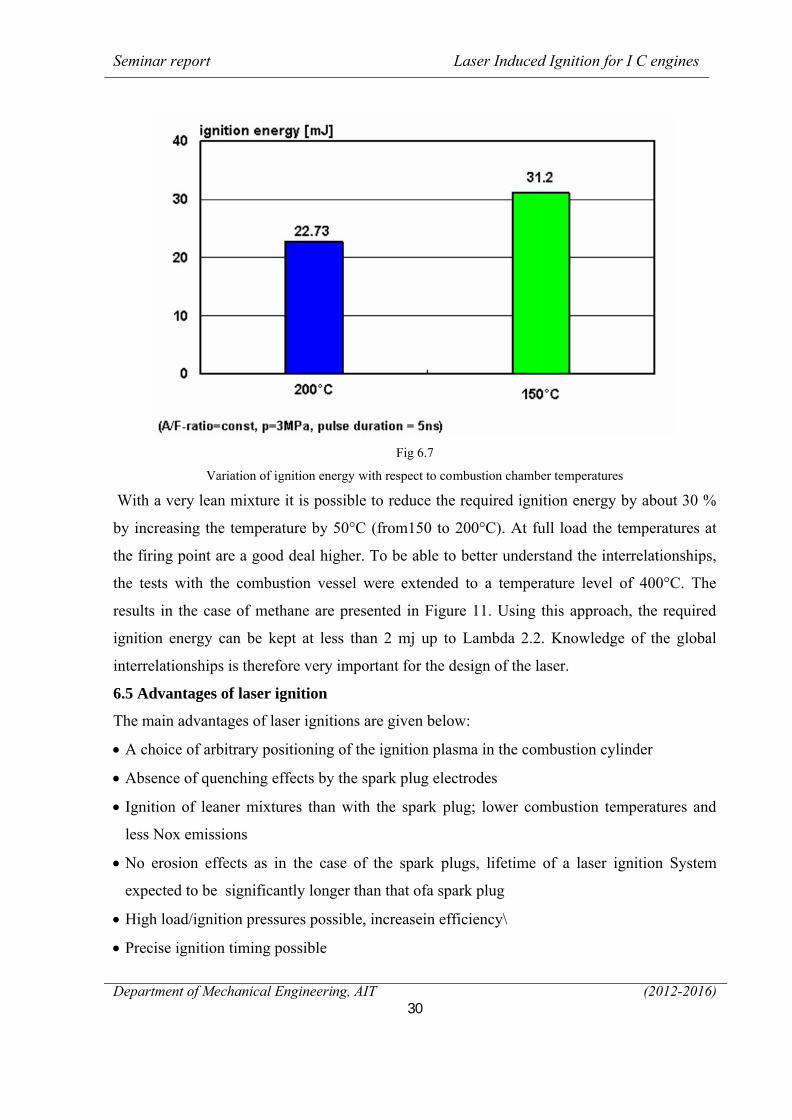
Another approach is to improve ignition conditions and flame propagation by
increasing combustion chamber temperatures. As well, this allows the required ignition
energies to be reduced considerably. An example regarding this approach is shown in Figure
below.
Seminar report Laser Induced Ignition for I C engines
Department of Mechanical Engineering, AIT (2012-2016)30
Fig 6.7
Variation of ignition energy with respect to combustion chamber temperatures
With a very lean mixture it is possible to reduce the required ignition energy by about 30 %
by increasing the temperature by 50°C (from150 to 200°C). At full load the temperatures at
the firing point are a good deal higher. To be able to better understand the interrelationships,
the tests with the combustion vessel were extended to a temperature level of 400°C. The
results in the case of methane are presented in Figure 11. Using this approach, the required
ignition energy can be kept at less than 2 mj up to Lambda 2.2. Knowledge of the global
interrelationships is therefore very important for the design of the laser.
6.5 Advantages of laser ignition
The main advantages of laser ignitions are given below:
∑ A choice of arbitrary positioning of the ignition plasma in the combustion cylinder
∑ Absence of quenching effects by the spark plug electrodes
∑ Ignition of leaner mixtures than with the spark plug; lower combustion temperatures and
less Nox emissions
∑ No erosion effects as in the case of the spark plugs, lifetime of a laser ignition System
expected to be significantly longer than that ofa spark plug
∑ High load/ignition pressures possible, increasein efficiency\
∑ Precise ignition timing possible
Seminar report Laser Induced Ignition for I C engines
Department of Mechanical Engineering, AIT (2012-2016)31
∑ Exact regulation of the ignition energy deposited in the ignition plasma
∑ Easier possibility of multipoint ignition
∑ Shorter ignition delay time and shorter combustion time
∑ The thermodynamic requirements of a high compression ratio and a high power density are
fulfilled well by laser ignition
6.6 Future Research Needs and Shortcomings
Delivering the beam through free space and channeling it into the combustion chamber
through the optical plug achieved the best results – reducing the Coefficient of Variation,
making combustion smoother and more fuelefficient. The team was particularly keen to
deliver the beam via optical fiber, since this was likely to be less susceptible to engine
vibration and could facilitate improved engine layout. They tried out a range of optical fibers,
including silica and sapphire, and experimented with different internal fiber structures, core
sizes and beam coupling optics. Delivering the beam via optical fiber proved to be more
difficult than the research team had hoped. The fiber didn’t respond well to engine vibration,
which increased the divergence of the output beam and reduced the beam mode quality.
Bending the fiber was also problematical and up to 20 per cent of the beam energy was lost
with small bend diameters, while tight bends caused the fiber to fail altogether after a period.
What’s more, the high density of laser energy can cause immediate or long term degradation,
leading to loss of beam transmission – and therefore loss of ignition. Careful design of laser
parameters, fiber coupling and choice of optical media is crucial to avoid this. These problems
can be solved with further research.
Seminar report Laser Induced Ignition for I C engines
Department of Mechanical Engineering, AIT (2012-2016)32
CHAPTER - 7
CONCLUSION
Laser induced ignition of I C engines has been examined. The feasibility of a laser-induced
ignition system on a direct injected gasoline engine has been proven in long-term
experiments. Main advantages are are the almost free choice of the ignition location within
the combustion chamber, even inside the fuel spray. Significant reductions in fuel
consumption as well as reductions of exhaust gases show the potential of the laser ignition
process. Results indicate that pollution of the beam entrance window is not critical as
expected, even heavily polluted windows have had no influence on the ignition characteristics
of the engine. Measurements show that the required pulse energy for successful ignition
decreases with increasing pressure. Laser ignition is nonintrusive in nature; high energy can
be rapidly deposited, has limited heat losses, and is capable of multipoint ignition of
combustible charges. More importantly, it shows better minimum ignition energy requirement
than electric spark systems with lean and rich fuel/air mixtures. It also possesses potentials
for combustion enhancement and better immunity to spurious signals that may accidentally
trigger electric igniters. Although the laser will need to fire more than 50 times per second to
produce 3000 RPM, it will require less power than current spark plugs. The lasers can also
reflect back from inside the cylinders to relay information based on fuel type used and the
level of ignition, enabling cars to readjust the quantities of air and fuel for optimum
performance. At present, a laser ignition plug is very expensive compared to a standard
electrical spark plug ignition system and it is nowhere near ready for deployment. But the
potential and advantages certainly make the laser ignition more attractive in many practical
applications. It was found for the laser ignition tests with hydrogen that with higher initial
pressures the minimum pulse energy for ignition (MPE) decreases. That behaviour was also
found for methane. Fuel-lean biogas/air mixtures exhibit a slower combustion process
resulting in lower peak pressure and flame emission compared to methane-air mixtures of
similar air to fuel equivalence ratio. The applicability of the laser induced ignition as a future
ignition system for combustion engines with spray-guided combustion process could be
proved with the basic research.
Seminar report Laser Induced Ignition for I C engines
Department of Mechanical Engineering, AIT (2012-2016)33
CHAPTER - 8
REFERENCE
[1] Swapnil S. Harel, Mohnish Khairnar, Vipul Sonawane, “Laser Ignition System for IC
Engines”, International Journal of Science and Research (IJSR), Volume 3 Issue 7,
July2014.
[2] J. Ma, D. Alexander, and D. Poulain, “Laser spark ignition and combustion
characteristics of methane-air mixtures,” Combustion and Flame, pp. 492–506, 1998
[3] J. Syage, E. Fournier, R. Rianda, and R. Cohn, “Dynamics of flame propagation using
laser-induced spark initiation: Ignition energy measurements,” Journal of Applied
Physics, pp. 1499–1507, 1988.
[4] Lambda Physik, Manual for the LPX205 Excimer Laser,1991
[5] R. Hill, “Ignition-delay times in laser initiated combustion,” Applied Optics, pp.
2239–2242, 1981
[6] J. Ma, D. Alexander, and D. Poulain, “Laser spark ignition and combustion
Characteristics of methane-air mixtures,” Combustion and Flame 112 (4), pp.492–506,
1998
[7] J. Syage, E. Fournier, R. Rianda, and R. Cohn, “Dynamics of flame propagation
Using laser-induced spark initiation: Ignition energy measurements,” Journal of
Applied Physics 64 (3), pp. 1499–1507, 1988.
[8] Lambda Physik, Manual for the LPX205 Excimer Laser, 1991
[9] P. Ronney, “Laser versus conventional ignition of flames,” Opt. Eng. 33 (2), pp.
510–521, 1994.
[10] R. Hill, “Ignition-delay times in laser initiated combustion,” Applied Optics. 20
(13), pp. 2239–2242, 1981


![D - DFI engines.ppt [modalità compatibilità] - DFI engines.pdfDFI Engines CHARACTERISTICS 3-D IGNITION MAP Ignition angle. Throttle opening Engine revolutions. DFI Engines. ... P0563](https://img.pdfslide.us/doc/110x75/5e800233e457415cb10b52c0/d-dfi-modalit-compatibilit-dfi-enginespdf-dfi-engines-characteristics.jpg)