Embed Size (px)
Citation preview
workshopmanual
A 349A 360
workshopmanual
SPARK IGNITION ENGINES SERIES
A 349A 360
1
workshop manual SPARK IGNITION ENGINES SERIES A349 - A360
TABLES OF CONTENTS
123
TECHNICAL FEATURES..................................................................................pag. 3
SPECIAL TOOLS ..............................................................................................pag. 4
GENERAL INFORMATION...............................................................................pag. 51 General information for correct repairs
REFUELLING....................................................................................................pag. 51 Lubricant2 Fuel
ENGINE DISASSEMBLY ..................................................................................pag. 61 Engine preparation 2 Engine identification3 Flywheel extraction4 Head disassembly5 Timing cover removal6 Valves removal7 Camshaft removal8 Crankshaft removal
CHECKS AND OVERHAULS ...........................................................................pag. 71 Cylinder head2 Valves - guides - seats - valve springs - tappets3 Breather valve4 Cylinder 5 Connecting rod 6 Piston and rings7 Crankshaft8 Oil seal rings9 Bearings10 Camshaft11 Timing cover12 Crankcase 13 Speed governor 14 Carburetor15 Lubrication16 Electronic ignition 17 Spark plugs18 Recoil starter19 Electric starting 20 Oil watch device
4
5
6

2
workshop manual SPARK IGNITION ENGINES SERIES A349 - A360
ENGINE ASSEMBLY ........................................................................................pag. 221 Crankshaft and oil seal rings 2 Piston and connecting rods 3 Timing system4 Timing cover5 Flywheel assembly and coil gap adjustment6 Valves assembly 7 Cylinder head assembly8 Engine assembly9 Governor lever adjustment
ENGINE TEST...................................................................................................pag. 21 Starting with recoil starter2 Electric starting3 Carburetor and r.p.m. adjustment
STORAGE .........................................................................................................pag. 281 Temporary storage2 Preparation for starting
INSTALLATION.................................................................................................pag. 281 Inclination limits of operation2 Axial load - radial load and maximum overhang3 Overall dimensions4 Special power take-offs and flange
PISTON-CYLINDER OVERSIZE TABLE ..........................................................pag. 30
TOLERANCES OF CRANKSHAFT JOURNAL GRINDINGS ..........................pag. 30
CLEARANCES AND ADJUSTMENTS TABLE ................................................pag. 30
TORQUE SETTING...........................................................................................pag. 31
TROUBLE SHOOTING .....................................................................................pag. 31
7
8
9
10
11
12
13
14
15

3
workshop manual SPARK IGNITION ENGINES SERIES A349 - A360
A 349
Engine Type
A 360
SPARK IGNITION ENGINES Series A349-360
FOREWORDThis manual contains all the necessary information to repairing the A349-A360 engines. (Updating and modifications should be checked on the technical information sheets).
349
Displacement cm3
349
82
Bore mm
82
66
Strokemm
66
7,4 : 1
7,4 : 1
Compression Ratio
Standard R.P.M.
3200/3800
3200/3800
1 TECHNICAL FEATURES
4
workshop manual SPARK IGNITION ENGINES SERIES A349 - A360
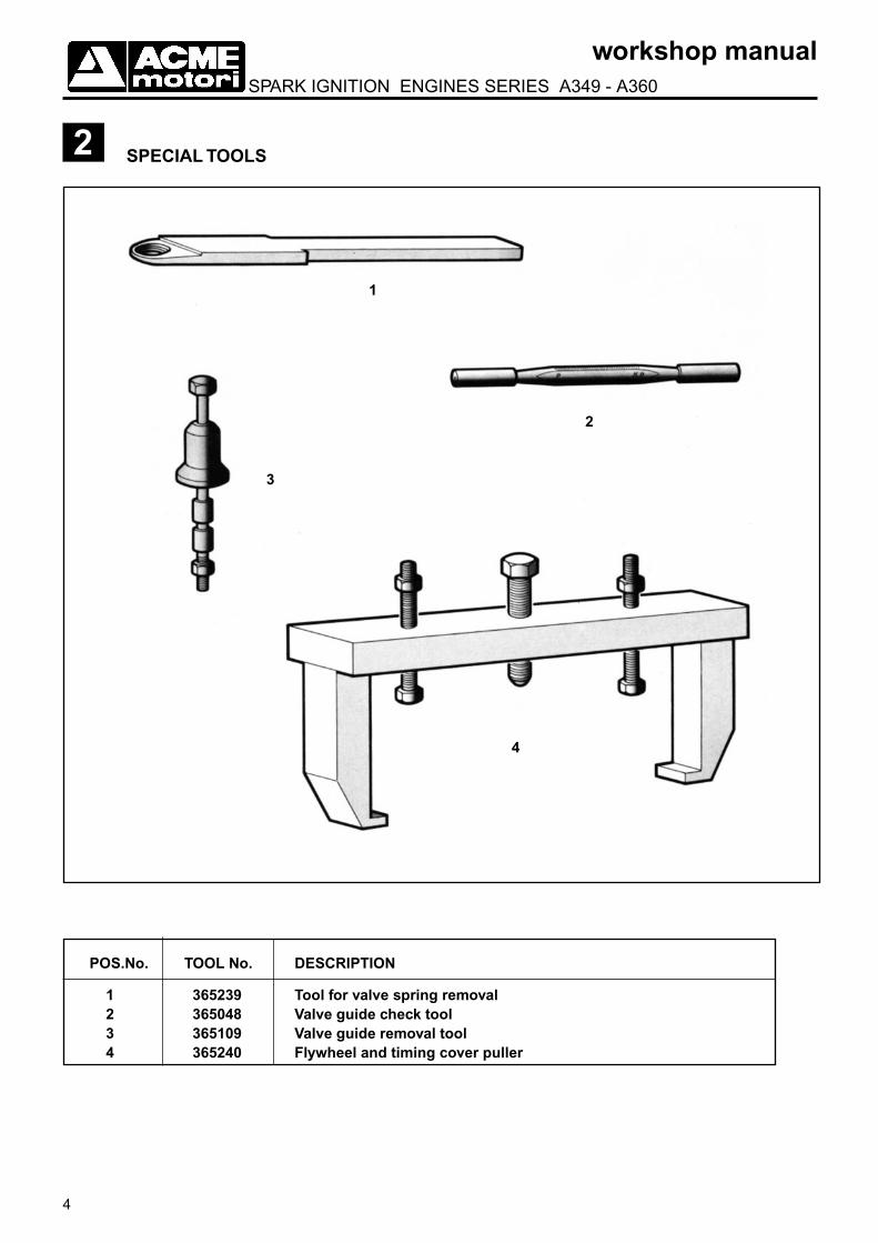
2 SPECIAL TOOLS
POS.No. TOOL No. DESCRIPTION
1 365239 Tool for valve spring removal 2 365048 Valve guide check tool 3 365109 Valve guide removal tool 4 365240 Flywheel and timing cover puller
1
2
3
4
5
workshop manual SPARK IGNITION ENGINES SERIES A349 - A360
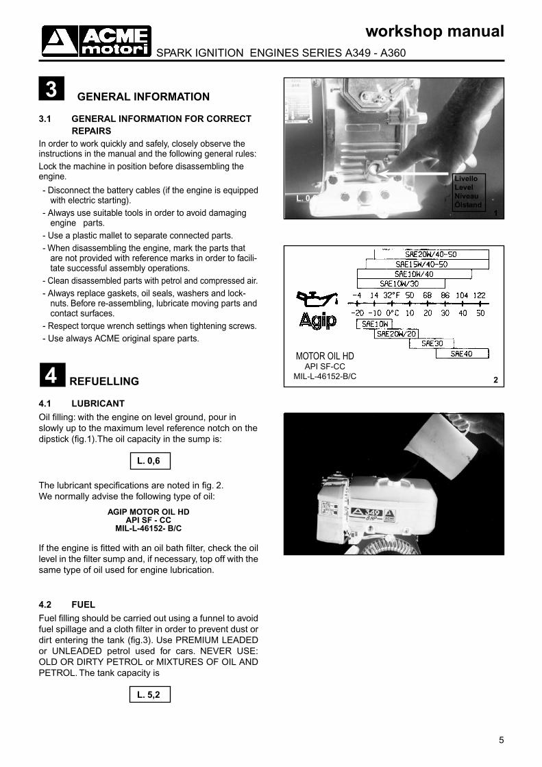
4.1 LUBRICANTOil filling: with the engine on level ground, pour in slowly up to the maximum level reference notch on the dipstick (fig.1).The oil capacity in the sump is:
L. 0,6
The lubricant specifications are noted in fig. 2.We normally advise the following type of oil: AGIP MOTOR OIL HD
API SF - CCMIL-L-46152- B/C
If the engine is fitted with an oil bath filter, check the oil level in the filter sump and, if necessary, top off with the same type of oil used for engine lubrication.
4.2 FUELFuel filling should be carried out using a funnel to avoid fuel spillage and a cloth filter in order to prevent dust or dirt entering the tank (fig.3). Use PREMIUM LEADED or UNLEADED petrol used for cars. NEVER USE: OLD OR DIRTY PETROL or MIXTURES OF OIL AND PETROL. The tank capacity is
L. 5,2
33.1 GENERAL INFORMATION FOR CORRECT REPAIRSIn order to work quickly and safely, closely observe the instructions in the manual and the following general rules:Lock the machine in position before disassembling the engine.
- Disconnect the battery cables (if the engine is equipped with electric starting).
- Always use suitable tools in order to avoid damaging engine parts.
- Use a plastic mallet to separate connected parts.- When disassembling the engine, mark the parts that
are not provided with reference marks in order to facili-tate successful assembly operations.
- Clean disassembled parts with petrol and compressed air.- Always replace gaskets, oil seals, washers and lock-
nuts. Before re-assembling, lubricate moving parts and contact surfaces.
- Respect torque wrench settings when tightening screws.- Use always ACME original spare parts.
4 REFUELLING
1
2
3
GENERAL INFORMATION
L. 5,2
MOTOR OIL HDAPI SF-CC
MIL-L-46152-B/C
L. 0,6
LivelloLevelNiveauÖlstand

6
workshop manual SPARK IGNITION ENGINES SERIES A349 - A360
4
5
6
ENGINE DISASSEMBLY
If the engine is mechanically worn-out, but the outside parts are still in good condition (tank, casing, flywheel, coil, carburettor, air filter, exhaust, fan cowl, cylinder head), the use of a “Short-Block” is advised (composed of crankcase, crankshaft, connecting rod, piston, timing cover and gasket set and ready to be completed by the outside parts). Once assembly operations have been completed, proceed with setting up.
5.1 ENGINE PREPARATIONAfter having drained the oil from the engine and emptied the fuel tank, place the engine on a work bench and disassemble the outside parts: tank, exhaust, air filter, carburettor, casing, recoil starter and fan cowl.
5.2 ENGINE IDENTIFICATIONThe engine type and serial number are shown on the identification plate positioned on the right hand side of the engine (fig.4) observing the engine from the flywheel side.
5.3 FLYWHEEL EXTRACTIONLoosen the flywheel locknut. Note: Remember that the thread is LEFT HANDED up to S/N 5015306, and starting from S/N 5015307 the crankshaft thread has been modified to RIGHT HANDED. Remove the washer and pulley.Using the puller No. 4 on page 4, remove the flywheel (fig. 5).
5
5.4 HEAD DISASSEMBLY Do not disassemble when hot to avoid deformation.Using a T-wrench loosen the screws that fix the cylin-der head to the crankcase.
7
versione
matricola
5.5 TIMING COVER REMOVALBefore removing the timing cover, release the governor spring from the governor lever (fig.7), then loosen the M6 screws that fix the timing cover to the crankcase, using puller No.4 on page 4, position the central screw on the opposite side from that used to extract the flywheel, tighten the two screws in the threaded holes on the timing cover (fig. 6)

7
workshop manual SPARK IGNITION ENGINES SERIES A349 - A360
8
9
10
11
P
5.7 CAMSHAFT REMOVALRotate the crankshaft until the timing marks on the camshaft gear and on the crankshaft gear are in correspondence (compression stroke and piston TDC). Them remove the camshaft.
5.8 CRANKSHAFT REMOVALRemove the connecting rod screws, the piston and the crankshaft. For bearings removal, use a universal puller with 2 or 3 fingers (fig.9)
5.6 VALVES REMOVALAfter removing the caps containing the shims for valve clearance adjustment and after positioning the piston at T.D.C., use the tool N.1 page 4 as shown at fig. 8. Should it be difficult, turn the lower cap until the slot on the cap faces the inside.Up to serial number 5004050 the valves clearance was carried out in this way:1) End of the valve stem grinded if the clearance was less of 0,10 for intake valve and 0,15 for exhaust valve.2) Valve Seat grinded if the clearance was more of 0,15 for intake valve and 0,20 for exhaust valve.Starting from S/N. 5004051 some caps have been fitted between valves and tappets, clearance is adjusted by varying the number of the shims in the cups (fig.11 parts 8 and 9)
11
5
6
7
910
8
4
6 CHECKS AND OVERHAULS
6.1 CYLINDER HEADIt is made of die-cast aluminium alloy. Clean all carbon deposits from the head and check that the head face P (fig. 10) is not deformed. If deformed, grind the working face by removing not more than 0,3 mm.
0,3 mm
6.2 VALVES - GUIDES - SEATS - VALVE SPRINGS - TAPPETS
VALVESAfter disassembling and cleaning with a metal brush, check that the valve heads are not deformed, burned or worn in the seats: replace the valves if damaged. If the general condition is good, recut the face track Pin the seat with a grinding of 45°.Parts of fig. 11:1) Crankcase 2) seats 3) guide-valve 4) valves 5) spring-plate 6) spring 7) valve plate 8) shims 9) cups 10) tappet 11) oil seal ring.

8
workshop manual SPARK IGNITION ENGINES SERIES A349 - A360
Following prolonged engine operation, the hammering of the valves on the seats, at high temperatures, hardens the track P (fig.16) making manual grinding impossible. The hardened surface must be removed using a grinder fitted on a seat refacer. The final procedure may be carried out with a manual cutter, as previously described (fig.15).Valve seat grinding will lead to the enlarging of track R that faces the valve on the seat. If R is wider than 2 mm, lower the face Q using an inverted cutter,(fig.17) until the R measurement is between:
1,3 ÷ 1,5 mm
12
13
14
15
VALVE GUIDESCheck that the valve guides are not scored; show signs of seizing or carbon deposits. Check the valve guides wear (fig. 13) by using a go-no-go INTERNAL gauge No.2 page 4.If the diameter of the guide exceeds the plug diameter, it should be replaced.In order to extract the valve guide from the seat,
proceed as follows:- heat the crankcase to a temperature between 100º
-120º C.- using the puller N. 3 pag. 4 remove the valve guide
and replace with the new ones (fig.14).- fit the valves in the new valve guides, and check
that it moves freely.
Check the guides, valves, and seats after assembly (fig.12):
VALVE SEATSDue to the special high nickel-chromium alloy content, cast iron valve seats are particularly resistant to the heat caused by combustion. For grinding, use a 45º tapered milling cutter with 28-35mm of diameter and 7mm of stem.
DIMENSION Nominal D. (mm) Limit (mm)
A 7,03 - 7,04 0,15
B 6,98 - 7,00 0,15
Inlet valve-guide 1,00 - 1,20 2,00 C Exhaust valve-guide 1,40 - 1,60 2,00
VALVE SEAT DIMENSIONS mm
Inlet seat
28-
Exhaust seat
-25
Milling cutter D.
3528
28 ÷ 35 mm

9
workshop manual SPARK IGNITION ENGINES SERIES A349 - A360
16
17
18
19
The final procedure for the valve and the seat should be carried out by spreading a layer of fine grain lapping paste in the seat and rotating the valve, using slight pressure and an alternating movement, until the surfaces are perfectly set (fig.18).
Wash the valve and seat thoroughly with oil or petrol to eliminate all traces of lapping paste or shavings.
To check the efficiency of the seal between the valve and seat, once lapping is finished proceed as follows:
1) Fit the valve on the head with the valve spring and valve retainers.2) Pour a few drops of diesel fuel or oil around the edge of the valve head.3) Direct compressed air inside the duct (intake/exhaust), taking care to plug the edges of the duct in order to avoid air leakage (fig.19).If air leakage causes bubbles between the seat and the valve, disassemble the valve and correct the seat grinding.The test can also be carried out by pushing the valve upward in the seat and then allowing it to return freely. If the recoil is both substantial and uniform, even when manually rotating the valve, this means that the valve seating is satisfactory. If not, continue the lapping operation until the aforementioned conditions have been achieved.If the seat needs to be replaced, proceed as follows:
1) Using a 2-3 mm drill bit, drill holes on the seat, completing the cut with a chisel, without damaging the housing.2) Extract the seat.3) Heat the head to a temperature of between 160º-180º C.4) Introduce the new seat using a press.
It is advisable that this type of operation is carried out at a specialized workshop.
10
workshop manual SPARK IGNITION ENGINES SERIES A349 - A360
20
21
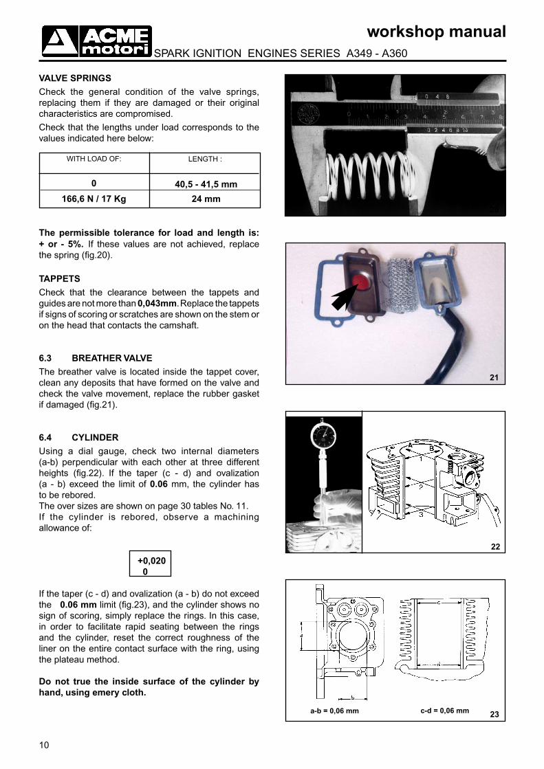
VALVE SPRINGSCheck the general condition of the valve springs, replacing them if they are damaged or their original characteristics are compromised.
Check that the lengths under load corresponds to the values indicated here below:
22
23
The permissible tolerance for load and length is: + or - 5%. If these values are not achieved, replace the spring (fig.20).
TAPPETSCheck that the clearance between the tappets and guides are not more than 0,043mm. Replace the tappets if signs of scoring or scratches are shown on the stem or on the head that contacts the camshaft.
6.3 BREATHER VALVEThe breather valve is located inside the tappet cover, clean any deposits that have formed on the valve and check the valve movement, replace the rubber gasket if damaged (fig.21).
6.4 CYLINDERUsing a dial gauge, check two internal diameters (a-b) perpendicular with each other at three different heights (fig.22). If the taper (c - d) and ovalization (a - b) exceed the limit of 0.06 mm, the cylinder has to be rebored.The over sizes are shown on page 30 tables No. 11.If the cylinder is rebored, observe a machining allowance of:
+0,020 0 If the taper (c - d) and ovalization (a - b) do not exceed the 0.06 mm limit (fig.23), and the cylinder shows no sign of scoring, simply replace the rings. In this case, in order to facilitate rapid seating between the rings and the cylinder, reset the correct roughness of the liner on the entire contact surface with the ring, using the plateau method.
Do not true the inside surface of the cylinder by hand, using emery cloth.
WITH LOAD OF: LENGTH :
a-b = 0,06 mm c-d = 0,06 mm
0
166,6 N / 17 Kg
40,5 - 41,5 mm
24 mm

11
workshop manual SPARK IGNITION ENGINES SERIES A349 - A360
24
25
26
If there is a slight step in the cylinder in zone A (fig.24), eliminate the difference using a lapping stone, in order to avoid ring damage.Upon completion clean the cylinder walls thoroughly with petrol or diesel fuel.
6.5 CONNECTING RODIt is made of a special aluminium alloy, and without inserted bearings, and is available in two under sizes. If replaced because of wear or seizing, it is advisable to regrind the crank pin and to fit a connecting rod with a reduced size big-end hole.For under sizes see table No. 12 on page 30.
A hole on the crankshaft allows the lubrication between the big-end and crankpin. (see chapter N. 6.7 crankshaft and chapter N. 6.15 lubrication).
N.B.: After tightening the connecting rod screws lock them in place with the safety plate. There are two different type of safety plates (fig25): type A for industrial application with oil watch device.type B farming application. The oil dipper safety plate type B has to be fitted facing the inside part of the crankcase. The allowance between the small end and piston pin must be:
min 0,015 max 0,025 limit 0,070
In order to correctly control the parallelism of the axes between the big-end and the small end, proceed as follows (fig.26).1) Insert the pin in the hole at the small end and a calibrated pin in the big-end hole.2) Rest the two ends of the pin on two drill blocks
positioned on a level surface.3) Using a column dial gauge, check that the difference
between the two ends of the pin does not exceed 0.05 mm, if this value is surpassed the connecting rod will require alignment.
The alignment operation can be carried out using a small mechanical press:
a) Position the connecting rod on two shims, making sure that it is perfectly horizontal with the press surface.
b) Using the press, apply pressure in jolts to the rod on the opposite side from where the error was detected, until the parallelism returns within the values noted in point 3.
A B
12
workshop manual SPARK IGNITION ENGINES SERIES A349 - A360
27
28
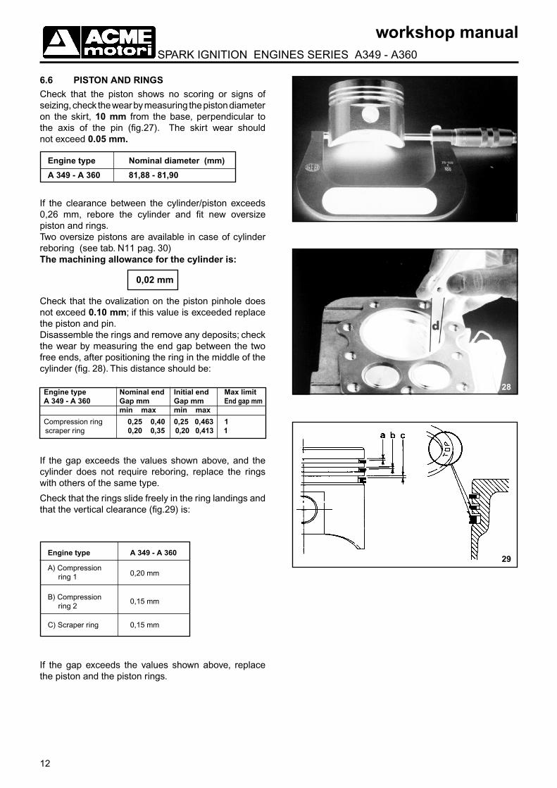
6.6 PISTON AND RINGSCheck that the piston shows no scoring or signs of seizing, check the wear by measuring the piston diameter on the skirt, 10 mm from the base, perpendicular to the axis of the pin (fig.27). The skirt wear should not exceed 0.05 mm.
Engine type Nominal diameter (mm)
A 349 - A 360 81,88 - 81,90
If the clearance between the cylinder/piston exceeds 0,26 mm, rebore the cylinder and fit new oversize piston and rings.Two oversize pistons are available in case of cylinder reboring (see tab. N11 pag. 30)The machining allowance for the cylinder is:
0,02 mm
Check that the ovalization on the piston pinhole does not exceed 0.10 mm; if this value is exceeded replace the piston and pin.Disassemble the rings and remove any deposits; check the wear by measuring the end gap between the two free ends, after positioning the ring in the middle of the cylinder (fig. 28). This distance should be:
Engine type Nominal end Initial end Max limit A 349 - A 360 Gap mm Gap mm End gap mm min max min max
Compression ring 0,25 0,40 0,25 0,463 1 scraper ring 0,20 0,35 0,20 0,413 1
If the gap exceeds the values shown above, and the cylinder does not require reboring, replace the rings with others of the same type.
Check that the rings slide freely in the ring landings and that the vertical clearance (fig.29) is:
Engine type A 349 - A 360 A) Compression ring 1 0,20 mm
B) Compression ring 2
0,15 mm
C) Scraper ring 0,15 mm
If the gap exceeds the values shown above, replace the piston and the piston rings.
29

13
workshop manual SPARK IGNITION ENGINES SERIES A349 - A360
30
31
6.7 CRANKSHAFTRemove the plug from the crankshaft oil duct (fig. 30); with the aid of a metal scraper clean the inside of the oil duct and the oil slinger. After cleaning the duct and slinger, close the oil duct with a new plug, and then test the plug sealing with compressed air.
Check that the main journal and crank pin are not scored and show no signs of seizing. Slight scores or notches can be taken out using a fine file and finished with emery cloth type 600.Check that the cones, keys and end threads are not deformed and free of notches.
Take a measurement, using a micrometer, according to two perpendicular diameters, to check wear and ovalization of the crank pin and main journal (fig. 31).If the wear of the crank pin exceeds the limit of the 0.10 mm, grind it and fit a new connecting rod with reduced size big-end hole. For connecting rod under sizes see table N.12 pag. 30.
When grinding, the allowance for the crank pin is:
0,0000
-0,011 mm
The surface must be finished without scoring, to a roughness of 0.4 umm Ra.
NOTE: 1) When grinding the crank pin restore the radius value
to original specification (2,7 - 3,0mm).
2) The main journals must not be ground.
6.8 OIL SEAL RINGCheck that the oil seals are not hardened on the internal contact edge with the crankshaft and that they do not show any signs of cracks or wear. If they do, replaced them with new ones (Oil seal ring dimensions are shown on chapter 6.12).
14
workshop manual SPARK IGNITION ENGINES SERIES A349 - A360
32
33
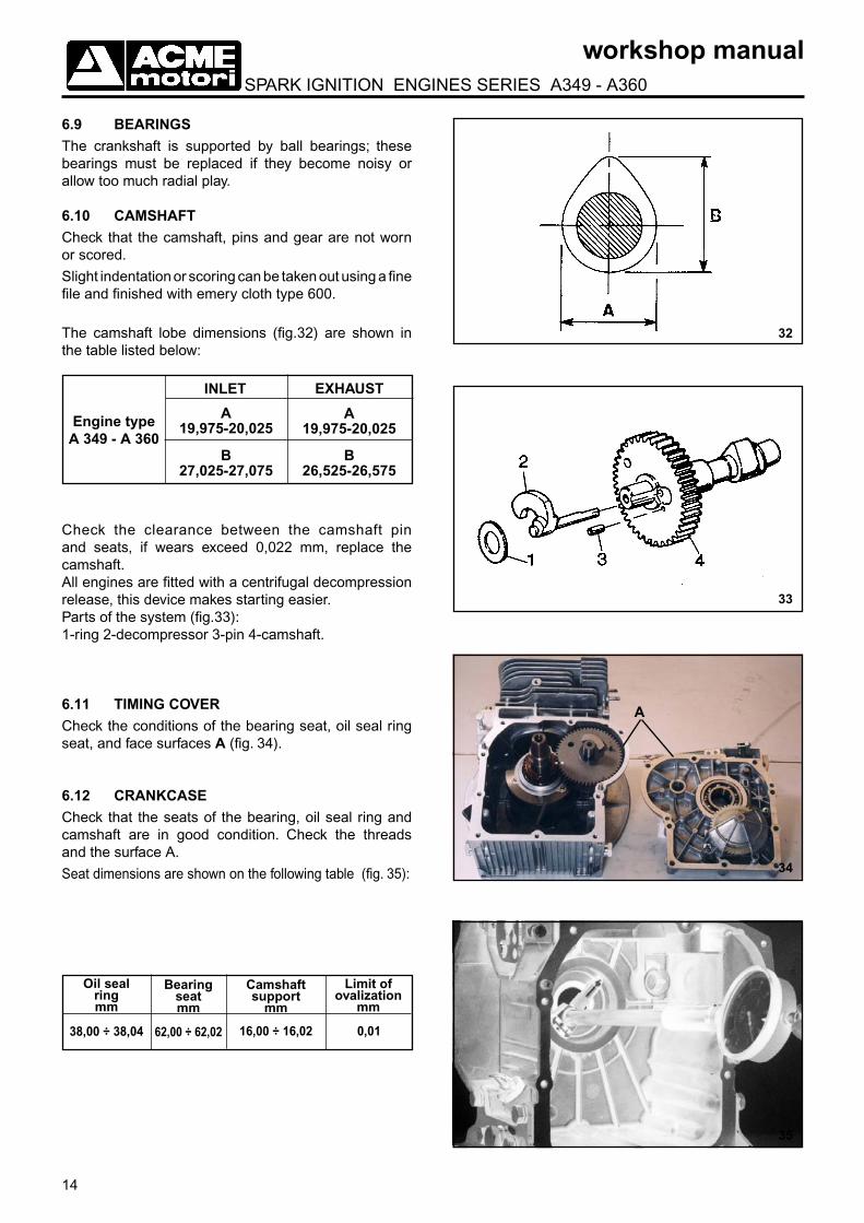
6.9 BEARINGSThe crankshaft is supported by ball bearings; these bearings must be replaced if they become noisy or allow too much radial play.
6.10 CAMSHAFTCheck that the camshaft, pins and gear are not worn or scored.
Slight indentation or scoring can be taken out using a fine file and finished with emery cloth type 600.
The camshaft lobe dimensions (fig.32) are shown in the table listed below:
Engine type A 349 - A 360
INLET EXHAUST
B27,025-27,075
A19,975-20,025
A19,975-20,025
B26,525-26,575
34
35
Check the clearance between the camshaft pin and seats, if wears exceed 0,022 mm, replace the camshaft.All engines are fitted with a centrifugal decompression release, this device makes starting easier.Parts of the system (fig.33):1-ring 2-decompressor 3-pin 4-camshaft.
6.11 TIMING COVERCheck the conditions of the bearing seat, oil seal ring seat, and face surfaces A (fig. 34).
6.12 CRANKCASECheck that the seats of the bearing, oil seal ring and camshaft are in good condition. Check the threads and the surface A.
Seat dimensions are shown on the following table (fig. 35):
Oil seal ring mm
Bearing seat mm
Camshaftsupport
mm
Limit of ovalization
mm
38,00 ÷ 38,04 62,00 ÷ 62,02 16,00 ÷ 16,02 0,01
A

15
workshop manual SPARK IGNITION ENGINES SERIES A349 - A360
36
6.13 SPEED GOVERNORThe speed governor has centrifuge counterweights (fig. 36).
The two (F) flyweights, pulled outward by centrifugal force, pushing (A) cap axially and this cap by means of a series of levers opens the carburettor throttle plate (C).The governor spring (D), put under tension by the accelerator (E), works against the action of the centrifugal force. The balance between two forces keeps the speed of rotation virtually constant as the load changes.Every position of the accelerator lever corresponds to a load variation on the spring and therefore to a situation of balance between the tension of the spring and the centrifugal force of the flyweights at different RPMs.Check that the gear rotates freely on its pivot and make sure that the flyweights move freely on their seats.The play between the cap and its pivot should be:
0,07 - 0,15 mm
In case of excessive play, the cap must be replaced.

16
workshop manual SPARK IGNITION ENGINES SERIES A349 - A360
6.14 CARBURETORDetails of fig. 37. 1) throttle rod 9) drain valve 2) air adjustment screw 10) float chamber3) spring 11) gasket4) throttle 12) floating pin5) spring 13) needle valve6) screw 14) idle jet 7) main jet 15) choke plate8) float 16) choke plate command rod
CARBURETOR CHARACTERISTICS For standard engines with dry air filter
engine carburetor needle main Idle Type Type Valve jet jet A 349 FHBC22-17 1,5 76 48 A 360 FHBC24-19 1,5 86 40
For cleaning and checks, proceed as follows:
-Totally disassemble the carburettor and carefully wash all parts with petrol or diesel fuel. Never use sharp metal points when cleaning the jets and calibrated channels.-Check the needle valve sealing and sliding movement
in the seat. Replace if necessary.
-Check the condition and free movement of the float.
-Check that the throttle rod is free to rotate throughout
its field of action, and that there is not excessive
clearance between the rod and the seat allowing
air infiltration.
-Check that the choke plate is not worn and that it rotates freely.
6.15 LUBRICATIONLubrication of internal moving parts is by means of oil, taken from the governor gear, and centrifuged by the rotation of the crankshaft inside the slinger. (fig.38)
The oil filtering is made by centrifugal force, when the engine is running, oil is collected by the governor gear and pushed inside the slinger where impurity are deposited. Clean the slinger and oil duct according to pag 13 chapter 6.7.
1
10
11
12
14
15
16
23
4
56
78
9
13
37
38
17
workshop manual SPARK IGNITION ENGINES SERIES A349 - A360
0,8 mm
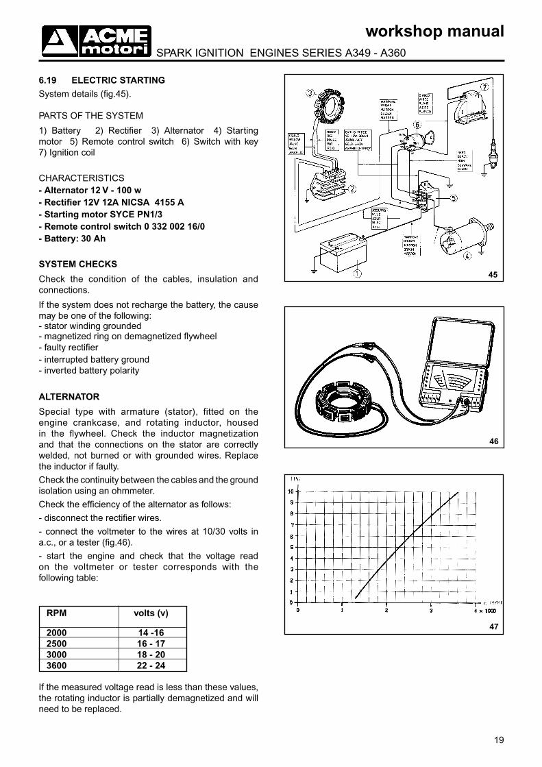
6.17 SPARK PLUGSClean the electrodes with a metal brush and compressed air, check that the gap between electrodes (FIG. 41) is between:
0,8 mm
If the insulating material is splintered or the electrodes are worn, replace with a spark plug that has the appropriate thermal rating, as shown in the table
SPARK PLUG BRAND
BOSCH WR 10 AC
CHAMPION RL 95 YC
NGK BR 5 HS
39
40
41
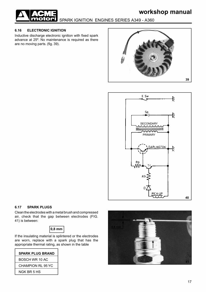
6.16 ELECTRONIC IGNITIONInductive discharge electronic ignition with fixed spark advance at 25º. No maintenance is required as there are no moving parts. (fig. 39).
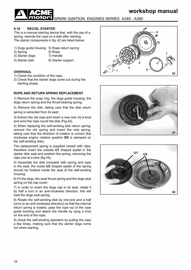
SECONDARY
PRIMARY
18
workshop manual SPARK IGNITION ENGINES SERIES A349 - A360
42
4
5
61
2
37
8
43
44
U1 U2
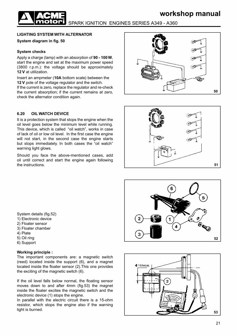
6.18 RECOIL STARTERThis is a manual starting device that, with the use of a spring, rewinds the rope on a disk after starting.The starter components in fig. 42 are listed below:
1) Dogs guide housing 5) Rope return spring2) Spring 6) Rope3) Starter dogs 7) Handle 4) Starter disk 8) Starter support
OVERHAUL1) Check the condition of the rope.2) Check that the starter dogs come out during the
starting phase.
ROPE AND RETURN SPRING REPLACEMENT
1) Remove the snap ring, the dogs guide housing, the dogs return spring and the thrust bearing spring;
2) Remove the disk, taking care that the disk return spring is extracted from its seat;
3) Extract the old rope and insert a new one, tie a knot and wind the rope round the disk (Fig.43).
4) When replacing the self-winding disk return spring: remove the old spring and insert the new spring, taking care that the direction of rotation is correct (the clockwise engine rotation position DX is stamped on the self-winding disk);
The replacement spring is supplied closed with clips, therefore insert the outside U1 shaped eyelet in the starter disk seat and position the spring, removing the clips one at a time (fig.44);
5) Assemble the disk complete with spring and rope in the seat, the inside U2 shaped eyelet of the spring should be hooked inside the seat of the self-winding housing;
6) Fit the dogs, the axial thrust spring and the dogs seal spring on the cap cover;
7) In order to insert the dogs cap in its seat, rotate it by half a turn in an anti-clockwise direction, this will load the dogs seal spring;
8) Rotate the self-winding disk by one-one and a half turns (in an anti-clockwise direction) so that the internal return spring is loaded, pass the rope out of the rope guide bushing and attach the handle by tying a knot on the end of the rope;
9) check the self-winding operation by pulling the rope a few times, making sure that the starter dogs come out when starting.
19
workshop manual SPARK IGNITION ENGINES SERIES A349 - A360
2000 14 -162500 16 - 173000 18 - 203600 22 - 24
46
47
45
6.19 ELECTRIC STARTING System details (fig.45).
PARTS OF THE SYSTEM
1) Battery 2) Rectifier 3) Alternator 4) Starting motor 5) Remote control switch 6) Switch with key 7) Ignition coil
CHARACTERISTICS- Alternator 12 V - 100 w- Rectifier 12V 12A NICSA 4155 A- Starting motor SYCE PN1/3- Remote control switch 0 332 002 16/0- Battery: 30 Ah
SYSTEM CHECKS
Check the condition of the cables, insulation and connections.
If the system does not recharge the battery, the cause may be one of the following:- stator winding grounded- magnetized ring on demagnetized flywheel - faulty rectifier- interrupted battery ground - inverted battery polarity
ALTERNATOR
Special type with armature (stator), fitted on the engine crankcase, and rotating inductor, housed in the flywheel. Check the inductor magnetization and that the connections on the stator are correctly welded, not burned or with grounded wires. Replace the inductor if faulty.
Check the continuity between the cables and the ground isolation using an ohmmeter.
Check the efficiency of the alternator as follows:
- disconnect the rectifier wires.
- connect the voltmeter to the wires at 10/30 volts in a.c., or a tester (fig.46).
- start the engine and check that the voltage read on the voltmeter or tester corresponds with the following table:
RPM volts (v)
If the measured voltage read is less than these values, the rotating inductor is partially demagnetized and will need to be replaced.

20
workshop manual SPARK IGNITION ENGINES SERIES A349 - A360
49
RECTIFIER
The rectifier should be checked in the following way:
- check the efficiency of the connections
- connect a 10 A ampmeter between the positive pole of the battery and the positive terminal of the rectifier- connect a 20 V voltmeter between the battery poles- allow the battery voltage to drop below 13 V, by starting the engine a few times.
In the diagram fig. 47 the current intensity flow is shown in relation to the variation of the engine r.p.m, with constant battery voltage of 12.5 V and ambient temperature of +25° C.If the charge is zero with 12.5 V battery reading, replace the rectifier and check the charge conditions.If the charge conditions remain unchanged, check the condition of the alternator.
IMPORTANT: The rectifier requires only a few seconds to be damaged if allowed to function when disconnected from the battery.
STARTING MOTOR
The starting motor is SYCE PN1 12 v - 0.15 KW type.
Fig. 48 shows the motor parts. The parts marked with a code number are available as spare parts.
BATTERY
The battery (not supplied by ACME) must provide a voltage of 12 V and a capacity of not less than 30 Ah.
N.B.: The battery capacity functions according to ambient temperature, therefore batteries with greater capacities are required for particularly low temperatures.
STARTING PANEL
Fig. 49 shows the different positions of the key switch.The first position, in clockwise rotation 1 (Running), activates the battery charging circuit; the second position (Starting) activates the starting motor. When the engine is running the key should be placed in the first position (Running). When the engine is stopped the key should be in the stop position; if left in the first position, the rectifier will be damaged and the battery will discharge (fig. 49).
563557563555
325218563561579045563560563558
563557
563122 48
375148
850120
21
workshop manual SPARK IGNITION ENGINES SERIES A349 - A360
50
51
LIGHTING SYSTEM WITH ALTERNATOR
System diagram in fig. 50
System checksApply a charge (lamp) with an absorption of 90 - 100 W, start the engine and set at the maximum power speed (3800 r.p.m.): the voltage should be approximately 12 V at utilization.
Insert an ampmeter (10A bottom scale) between the 12 V pole of the voltage regulator and the switch.If the current is zero, replace the regulator and re-check the current absorption; if the current remains at zero, check the alternator condition again.
6.20 OIL WATCH DEVICEIt is a protection system that stops the engine when the oil level goes below the minimum level while running. This device, which is called “oil watch”, works in case of lack of oil or low oil level. In the first case the engine will not start, in the second case the engine starts but stops immediately. In both cases the “oil watch” warning light glows.
Should you face the above-mentioned cases, add oil until correct and start the engine again following the instructions.
System details (fig.52)1) Electronic device2) Floater sensor3) Floater chamber4) Plate5) Oil ring6) Support
Working principle : The important components are: a magnetic switch (reed) located inside the support (6), and a magnet located inside the floater sensor (2).This one provides the exciting of the magnetic switch (6).
If the oil level falls below normal, the floating sensor moves down to and after 4mm (fig.53) the magnet inside the floater excites the magnetic switch and the electronic device (1) stops the engine.In parallel with the electric circuit there is a 15-ohm resistor, which stops the engine also if the warning light is burned.
52
49-b
53
6
1

22
workshop manual SPARK IGNITION ENGINES SERIES A349 - A360
ENGINE ASSEMBLY
- Correct engine assembly should be carried out in the following order:
- Before starting assembly operations, make sure that all parts are suitably clean.
- Lubricate the moving parts with oil to prevent sei-zing during the first moments of operation.
- Use clean oil for lubrification parts.
- Replace all gaskets and oil seal rings.
7
54a
7.1 CRANKSHAFT AND OIL SEAL RINGS.
Heat the bearing flywheel side to a temperature of between 120ºC - 130ºC, insert the bearing on the crankshaft until it makes contact with the shoulder on the crankshaft.
Put the protective bushing on the flywheel side thread then insert the complete crankshaft on the crankcase (fig. 54a).Insert new oil seal ring on the crankcase seat by using a uniform pressure on the surface.
NOTE: A damaged oil seal ring may allow air to be introduced into the crankcase, causing breather problems.
54b

23
workshop manual SPARK IGNITION ENGINES SERIES A349 - A360
7.2 PISTON AND CONNECTING RODS
The piston and the connecting rod must be assembled in a particular way. For correct assembly operations proceed as follows:
- the connecting rod must be fitted using the triangular reference marks on the big end facing the fitter (fig. 56), the piston must be assembled with the crankshaft forged on the top of the piston facing the flywheel (see fig. 57).
- fit the piston pin without pre-heating the piston, pressing into place manually. Lock in position using the pin retainers.
- fit the rings on the piston with the top mark (fig 54b) facing upward, rotate the ends of the rings so that they are staggered by 120 degrees.
- oil the cylinder liner and the piston, introduce the piston with the crankshaft forged above the piston crown facing the flywheel side. Use a normal ring-tightening band (commercially available) to collapse the piston rings (fig. 55).
- oil the crankshaft and the connecting rod big end, fit the cap on the connecting rod (the two triangular notches must face outward), tighten the connecting rod screws with a torque wrench (fig. 58) at a torque of:
11,8 Nm - 1,2 Kgm
- lock the screws in position with the safety plate (fig.59).
- safety plate with oil dipper must be toward the inside part of the crankcase.
- check that the crankshaft rotates freely.
55
56
57
58
24
workshop manual SPARK IGNITION ENGINES SERIES A349 - A360
59
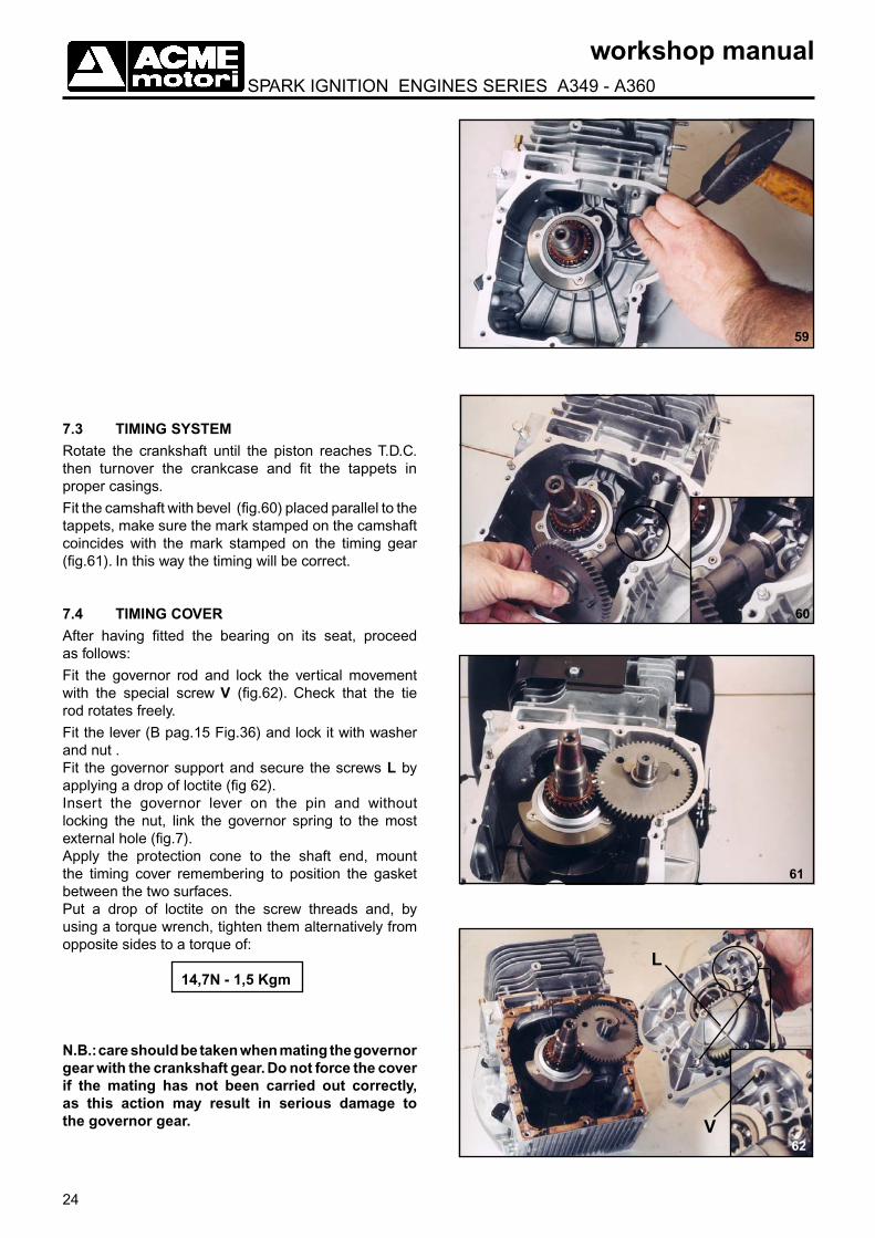
7.3 TIMING SYSTEMRotate the crankshaft until the piston reaches T.D.C. then turnover the crankcase and fit the tappets in proper casings.
Fit the camshaft with bevel (fig.60) placed parallel to the tappets, make sure the mark stamped on the camshaft coincides with the mark stamped on the timing gear (fig.61). In this way the timing will be correct.
7.4 TIMING COVERAfter having fitted the bearing on its seat, proceed as follows:
Fit the governor rod and lock the vertical movement with the special screw V (fig.62). Check that the tie rod rotates freely.
Fit the lever (B pag.15 Fig.36) and lock it with washer and nut .Fit the governor support and secure the screws L by applying a drop of loctite (fig 62).Insert the governor lever on the pin and without locking the nut, link the governor spring to the most external hole (fig.7).Apply the protection cone to the shaft end, mount the timing cover remembering to position the gasket between the two surfaces.Put a drop of loctite on the screw threads and, by using a torque wrench, tighten them alternatively from opposite sides to a torque of:
14,7N - 1,5 Kgm
N.B.: care should be taken when mating the governor gear with the crankshaft gear. Do not force the cover if the mating has not been carried out correctly, as this action may result in serious damage to the governor gear.
61
60
L
V62

25
workshop manual SPARK IGNITION ENGINES SERIES A349 - A360
64
65
66
63
7.5 ALTERNATOR - FLYWHEEL ASSEMBLY AND COIL GAP ADJUSTMENT
Fit the alternator on the engine crankcase (if provided), check the condition of the stator cables, insert the cables into the housing and check that they are held in position by the steel plate. Clean flywheel and crankshaft taper before assembling flywheel to crankshaft.Assemble the flywheel, after having checked the condition of the magnet and that it is securely attached to the flywheel. Tighten the flywheel with a torque wrench to a torque of:
137,2 N - 14 Kgm
Remember that the thread is LEFT HANDED up to the S/N 5015306, and that starting from S/N 5015307 the crankshaft thread has been modified to RIGHT HANDED.Fit the coil on the support without tightening the screws. The coil is provided with slots, slide the coil to the right up to the end of the slots (fig63) then, using a feeler gauge, positioned between the coil and the magnet, check the correct value of the gap (fig. 64), which should be between:
0,45 ÷ 0,50 mm
lock the coil screws in the correct position to a torque of:
11,8 N - 1,2 Kgm
7.6 VALVES ASSEMBLYFit the valves into their seats, move the piston to T.D.C. compression stroke with close valves, with a finger press down the valve’s head and check the gap with a feeler gauge (fig. 66), between valve’s stem and tappet, according to the following table:
INTAKE VALVE 0,10 - 0,15 mm
EXHAUST VALVE 0,15 - 0,20 mm
N.B.: Up to the serial number 5004050 valves clearance were carried out by grinding the valve seats or grinding the end of the valve stems. Starting from the S/N. 5004051 caps have been fitted between valves and tappets, in this way the clearance can be adjusted by varying the number of the shims in the cups (fig.65). The shims for valve clearance adjustment are available in two thicknesses:
0,1mm 0,004in0,2mm 0,008inMount the valves proceeding as follow:
a) Insert the upper plate between the supporting spring and the surface plane on the engine block ; insert the spring equipped with the lower plate for valve locking;
b) Insert the valves into their seats, by locking them in their lower part by the suitable plates, using the tool N1 p/n 365239 pag. 4.
26
workshop manual SPARK IGNITION ENGINES SERIES A349 - A360
67
68
69
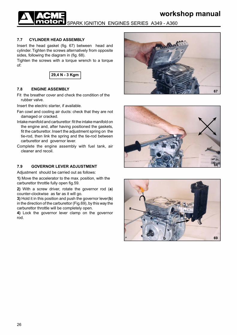
7.7 CYLINDER HEAD ASSEMBLYInsert the head gasket (fig. 67) between head and cylinder. Tighten the screws alternatively from opposite sides, following the diagram in (fig. 68).Tighten the screws with a torque wrench to a torque of:
29,4 N - 3 Kgm
7.8 ENGINE ASSEMBLYFit the breather cover and check the condition of the
rubber valve.
Insert the electric starter, if available.
Fan cowl and cooling air ducts: check that they are not damaged or cracked.
Intake manifold and carburettor: fit the intake manifold on the engine and, after having positioned the gaskets, fit the carburettor. Insert the adjustment spring on the tie-rod, then link the spring and the tie-rod between carburettor and governor lever.
Complete the engine assembly with fuel tank, air cleaner and recoil.
7.9 GOVERNOR LEVER ADJUSTMENTAdjustment should be carried out as follows:
1) Move the accelerator to the max. position, with the carburettor throttle fully open fig.59.
2) With a screw driver, rotate the governor rod (a) counter-clockwise as far as it will go.3) Hold it in this position and push the governor lever(b) in the direction of the carburettor (Fig.69), by this way the carburettor throttle will be completely open.4) Lock the governor lever clamp on the governor rod.
a
b

27
workshop manual SPARK IGNITION ENGINES SERIES A349 - A360
71
70
72
b
a
c
8.1 STARTING WITH RECOIL STARTERAfter having carryng out the operations noted above, pull the rope sharply and allow the engine to turn over for a few seconds before opening the starter.
8.2 ELECTRIC STARTINGBefore turning the starter key, make sure that all connections are in order, especially the rectifier and the battery ground connections. Operating with the disconnected battery will cause rectifier failure after a few seconds. Starting procedures are the same as those of paragraph 8
8.3 CARBURETOR AND R.P.M. ADJUSTMENT1) Start the engine and let it run for a few minutes.2) Attach an r.p.m. counter to the end of the
crankshaft. Using screw A in fig.70, adjust the mini-mum speed to a value of 1200 - 1250 r.p.m.
3) With the engine at the minimum speed, fully tighten the air adjustment screw b (fig.71), and then loosen slowly (usually approximately two turns).The adjustment will be right when, leaving the accelerator lever in the minimum position, the highest rpm is found, then with the screw a adjust the minimum speed again. Such operation is particularly delicate and it is necessary to carry it out many times to be sure you have found the right position.
4) Move the accelerator lever to the max. position and check the r.p.m. (unloaded) using the r.p.m. counter, this value should be:
- for generating set models 3200 r.p.m.- for all other models 3800 r.p.m.N.B.: different governor springs are provided for different speeds.
5) Adjust the max. speed using the screw c on the control plate; once adjustments are completed tighten the locknut (fig.72)
ENGINE TEST8Attach the engine to a base or to the machine. Check the oil level in the engine sump (and in the air filter if it is an oil bath type).Fill the fuel tank with fuel. Open the fuel tap. If the carburettor has been replaced or overhauled, carry out an initial adjustment by fully tightening the air adjustment screw and then loosening it by approximately two turns.Close the choke and place the accelerator at the max. The engine is ready to be started.N.B.: For engines working with kerosene, the engine should be started on petrol, by turning the tap to the “gasoline” position. A few minutes after starting, the tap can be turned to the “kerosene” position.
28
workshop manual SPARK IGNITION ENGINES SERIES A349 - A360
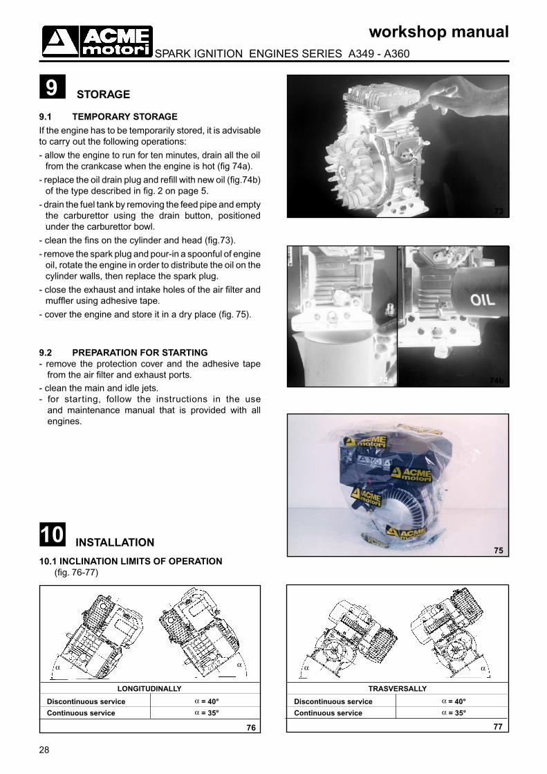
STORAGE99.1 TEMPORARY STORAGEIf the engine has to be temporarily stored, it is advisable to carry out the following operations:
- allow the engine to run for ten minutes, drain all the oil from the crankcase when the engine is hot (fig 74a).
- replace the oil drain plug and refill with new oil (fig.74b) of the type described in fig. 2 on page 5.
- drain the fuel tank by removing the feed pipe and empty the carburettor using the drain button, positioned under the carburettor bowl.
- clean the fins on the cylinder and head (fig.73).
- remove the spark plug and pour-in a spoonful of engine oil, rotate the engine in order to distribute the oil on the cylinder walls, then replace the spark plug.
- close the exhaust and intake holes of the air filter and muffler using adhesive tape.
- cover the engine and store it in a dry place (fig. 75).
9.2 PREPARATION FOR STARTING- remove the protection cover and the adhesive tape
from the air filter and exhaust ports.- clean the main and idle jets.- for starting, follow the instructions in the use
and maintenance manual that is provided with all engines.
Discontinuous service
Continuous service
LONGITUDINALLY TRASVERSALLY
α = 40°α = 35°
76 77
Discontinuous service
Continuous service
α = 40°α = 35°
αα α α
73
74b
7510 INSTALLATION
10.1 INCLINATION LIMITS OF OPERATION (fig. 76-77)
74a

29
workshop manual SPARK IGNITION ENGINES SERIES A349 - A360
78
Fr
Fa
S
10.3 OVERALL DIMENSIONS (fig. 79)
79
80
10.4 SPECIAL POWER TAKE-OFFS AND FLANGE (fig. 80)
10.2 AXIAL LOAD - RADIAL LOAD AND MAXIMUM OVERHANGThe axial thrust in both directions Fa (fig. 78) must not exceed 250 Kg.The maximum radial load Fr (fig.78) for belt transmission is 60 Kg with a maximum overhang (S) of the cylinder axis of 116 mm.When increasing the overhang (S) reduce the load Fr so that the bending moment Fr x S does not increase.
30
workshop manual SPARK IGNITION ENGINES SERIES A349 - A360
Engine Nominal First re-boring Second re-boring
Dia. mm piston P/N Dia. mm piston P/N Dia. mm piston P/N
A 349 +0,02 +0,02 +0,02
A 360 82
0 82,5 0 83
0
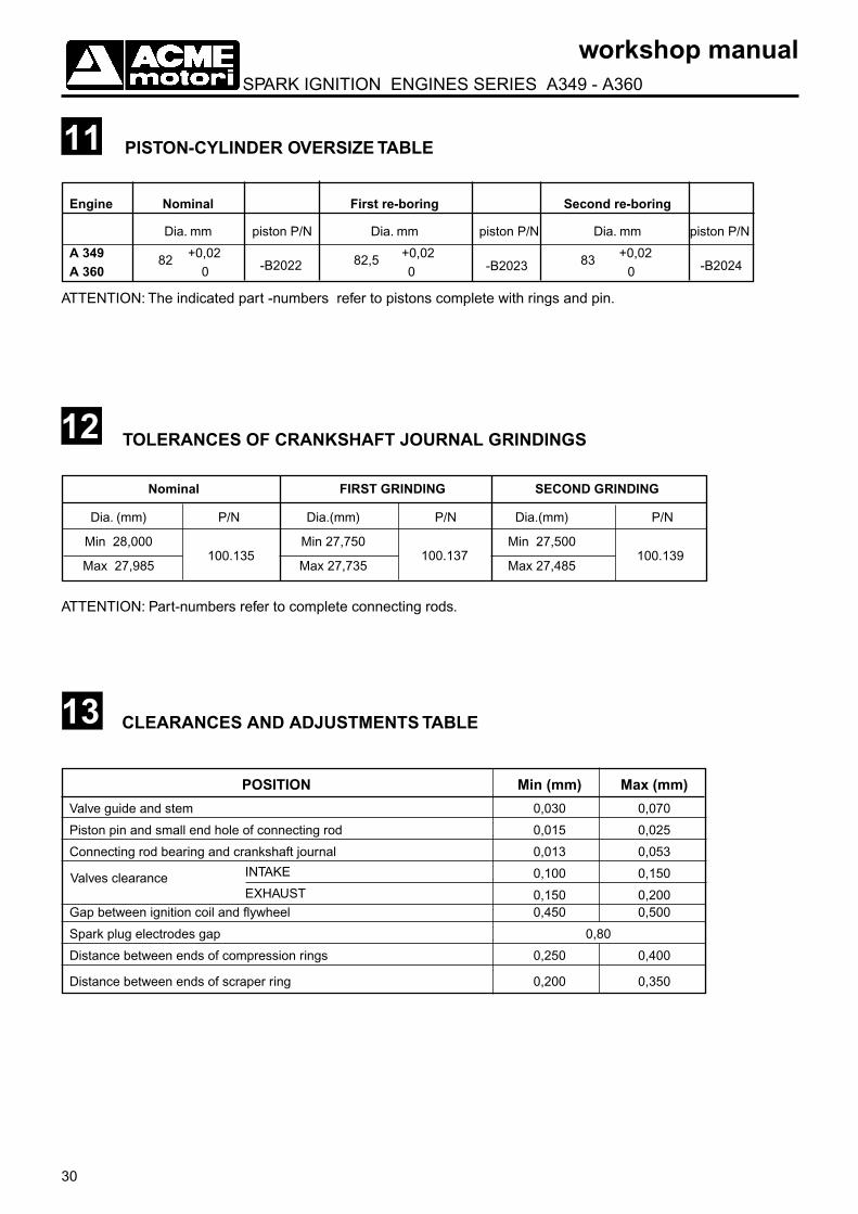
ATTENTION: The indicated part -numbers refer to pistons complete with rings and pin.
Gap between ignition coil and flywheel 0,450 0,500
Spark plug electrodes gap 0,80
Distance between ends of compression rings 0,250 0,400
Distance between ends of scraper ring 0,200 0,350
11 PISTON-CYLINDER OVERSIZE TABLE
12 TOLERANCES OF CRANKSHAFT JOURNAL GRINDINGS
Nominal FIRST GRINDING SECOND GRINDING
Dia. (mm) P/N Dia.(mm) P/N Dia.(mm) P/N
Min 28,000 Min 27,750 Min 27,500
Max 27,985 Max 27,735 Max 27,485
13 CLEARANCES AND ADJUSTMENTS TABLE
Valve guide and stem 0,030 0,070
Piston pin and small end hole of connecting rod 0,015 0,025
Connecting rod bearing and crankshaft journal 0,013 0,053
0,100 0,150
POSITION Min (mm) Max (mm)
-B2022 -B2023 -B2024
100.135 100.137 100.139
ATTENTION: Part-numbers refer to complete connecting rods.
Valves clearance INTAKE
EXHAUST 0,150 0,200
31
workshop manual SPARK IGNITION ENGINES SERIES A349 - A360
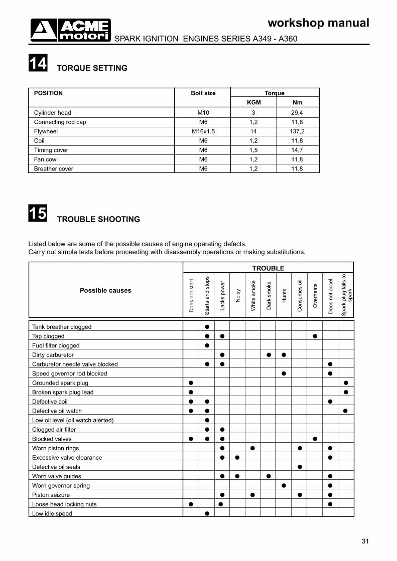
TORQUE SETTING
POSITION Bolt size Torque
KGM Nm
Cylinder head M10 3 29,4
Connecting rod cap M6 1,2 11,8
Flywheel M16x1,5 14 137,2
Coil M6 1,2 11,8
Timing cover M6 1,5 14,7
Fan cowl M6 1,2 11,8
Breather cover M6 1,2 11,8
14
15 TROUBLE SHOOTING
Listed below are some of the possible causes of engine operating defects.Carry out simple tests before proceeding with disassembly operations or making substitutions.
Doe
s no
t sta
rt
Sta
rts
and
stop
s
Lack
s po
wer
Noi
sy
Whi
te s
mok
e
Dar
k sm
oke
Hun
ts
Con
sum
es o
il
Ove
rhea
ts
Doe
s no
t acc
el.
Spa
rk p
lug
fails
to
spar
k
TROUBLE
Possible causes
Tank breather clogged
Tap clogged
Fuel filter clogged
Dirty carburetor
Carburetor needle valve blocked
Speed governor rod blocked
Grounded spark plug
Broken spark plug lead
Defective coil
Defective oil watch
Low oil level (oil watch alerted)
Clogged air filter
Blocked valves
Worn piston rings
Excessive valve clearance
Defective oil seals
Worn valve guides
Worn governor spring
Piston seizure
Loose head locking nuts
Low idle speed

ALWAYS USE ACME ORIGINAL SPARE PARTS
When ordering spare parts, always specify:
- engine model (on plate fig. 4)
- engine version code (on plate fig. 4)
- engine serial number (see fig. 5)
- make and model of equipment on wich engine is mounted
- part number and description.

ACME S.r.l. - 31049 VALDOBBIADENE (TREVISO) ITALY - VIA ERIZZO, 37 - TEL. (0423) 9701 - TELEFAX (0423) 973623 E-mail: [email protected] internet: www.acmemotori.com
E
ME
SS
O IL
N. R
EV
ISIO
NE
DAT
A
C
OD
ICE
04
/04/
2002
1
07/0
2
52
4148