Embed Size (px)
Citation preview

The National Standards Authority of Ireland and/or its licensors own the copyright in this standard.
All rights reserved.
This document was downloaded on
from a service provided by IHS Global Limited
trinityc, 04/04/2014, IHS Global Ltd

Eurocode 1: Actions on structures - Part1-5: General actions - Thermal actions (Including Irish National Annex)
Irish Standard
I.S. EN 1991-1-5:2003 + NA
No copying without NSAI permission except as permitted by copyright law.© NSAI 003
trinityc, 04/04/2014, IHS Global Ltd
P
91.010.30
19 December, 2003
I.S. EN 1991-1-5:2003 + NA
EN 1991-1-5:2003
This document is based on:
This document replaces:
30 June, 1998
Published:
ENV 1991-2-5:1997 ENV 1991-2-5:1997
Price Code:
This document was published
under the authority of the NSAI
and comes into effect on:
NSAI
1 Swift Square,
Northwood, Santry
Dublin 9
T +353 1 807 3800
F +353 1 807 3838
Údarás um Chaighdeáin Náisiúnta na hÉireann
W NSAI.ie
ICS number:
Incorporating amendments/corrigenda issued since publication:
NA to I.S. EN 1991-1-5:2003
19 November, 2003
T +353 1 857 6730
F +353 1 857 6729
W standards.ie
Sales:
trinityc, 04/04/2014, IHS Global Ltd
Eurocodes National Forword. This Irish Standard is the official English language version of EN 1991-1-5:2003, prepared by Technical Committee CEN TC 250 "Structural Eurocodes". This document supersedes ENV 1991-2-5:1997. This standard forms part of a package of 58 Eurocodes, which covers the basis of structural design, actions (loadings), the main structural materials, geotechnical design and design provisions for earthquakes. The European Commission document – Guidance Paper L – Application and Use of Eurocodes provides guidance on the elaboration, implementation and use of Eurocodes. Where a normative part of this EN allows for a choice to be made at the national level the range and possible choices are given in the normative text and a Note will qualify it as a Nationally Determined Parameter (NDP). To enable EN 1991-1-5:2003 to be used in Ireland the Nationally Determined Parameters will be published in a National Annex after public consultation has taken place. Until the National Annex is available, publication of this European Standard is solely for educational/training purposes and this standard should not be used in project design until the relevant National Annex is available. Note: For Use of this European Standard after Publication of the Irish National Annex. I.S. EN 1991-1-5:2003 may now be used in Ireland. The Nationally Determined Parameters, which have been prepared by the NSAI National Eurocode Advisory Committee, are included as an informative annex to the standard. The National Annex to I.S. EN 1991-1-5:2003 is also available as a separate publication as recommended in Guidance Paper L.
In Line with international standards practice the decimal point is shown as a comma (,) throughout this document.
I.S. EN 1991-1-5:2008
trinityc, 04/04/2014, IHS Global Ltd

This page is intentionally left BLANK.
I.S. EN 1991-1-5:2008
trinityc, 04/04/2014, IHS Global Ltd
EUROPEAN STANDARD
NORME EUROPÉENNE
EUROPÄISCHE NORM
EN 1991-1-5
November 2003
ICS 91.010.30 Supersedes ENV 1991-2-5:1997
English version
Eurocode 1: Actions on structures - Part 1-5: General actions -Thermal actions
Eurocode 1: Actions sur les structures - Partie 1-5: Actionsgénérales – Actions thermiques
This European Standard was approved by CEN on 18 September 2003.
CEN members are bound to comply with the CEN/CENELEC Internal Regulations which stipulate the conditions for giving this EuropeanStandard the status of a national standard without any alteration. Up-to-date lists and bibliographical references concerning such nationalstandards may be obtained on application to the Management Centre or to any CEN member.
This European Standard exists in three official versions (English, French, German). A version in any other language made by translationunder the responsibility of a CEN member into its own language and notified to the Management Centre has the same status as the officialversions.
CEN members are the national standards bodies of Austria, Belgium, Czech Republic, Denmark, Finland, France, Germany, Greece,Hungary, Iceland, Ireland, Italy, Luxembourg, Malta, Netherlands, Norway, Portugal, Slovakia, Spain, Sweden, Switzerland and UnitedKingdom.
EUROPEAN COMMITTEE FOR STANDARDIZATION
C O M I T É E U R O P É E N D E N O R M A LI S A T I O N
EUR OP ÄIS C HES KOM ITEE FÜR NOR M UNG
Management Centre: rue de Stassart, 36 B-1050 Brussels
© 2003 CEN All rights of exploitation in any form and by any means reservedworldwide for CEN national Members.
Ref. No. EN 1991-1-5:2003 E
I.S. EN 1991-1-5:2008
trinityc, 04/04/2014, IHS Global Ltd

trinityc, 04/04/2014, IHS Global Ltd
EUROPEAN STANDARD
NORME EUROPÉENNE
EUROPÄISCHE NORM
EN 1991-1-5:2003/AC
March 2009 Mars 2009 März 2009
ICS 91.010.30
English version Version Française Deutsche Fassung
Eurocode 1: Actions on structures - Part 1-5: General actions - Thermal actions
Eurocode 1: - Actions sur les structures - Partie 1-5: Actions générales - Actions
thermiques
Eurocode 1: Einwirkungen auf Tragwerke -Teil 1-5: Allgemeine Einwirkungen -
Temperatureinwirkungen
This corrigendum becomes effective on 11 March 2009 for incorporation in the three official language versions of the EN. Ce corrigendum prendra effet le 11 mars 2009 pour incorporation dans les trois versions linguistiques officielles de la EN. Die Berichtigung tritt am 11.März 2009 zur Einarbeitung in die drei offiziellen Sprachfassungen der EN in Kraft.
EUROPEAN COMMITTEE FOR STANDARDIZATION
C O M I T É E U R O P É E N D E N O R M A LI S A T I O N
EUR OP ÄIS C HES KOM ITEE FÜR NOR M UNG
Management Centre: Avenue Marnix 17, B-1000 Brussels
© 2009 CEN All rights of exploitation in any form and by any means reserved worldwide for CEN national Members. Tous droits d'exploitation sous quelque forme et de quelque manière que ce soit réservés dans le monde entier aux membres nationaux du CEN. Alle Rechte der Verwertung, gleich in welcher Form und in welchem Verfahren, sind weltweit den nationalen Mitgliedern von CEN vorbehalten.
Ref. No.:EN 1991-1-5:2003/AC:2009 D/E/F
I.S. EN 1991-1-5:2003/AC:2009
trinityc, 04/04/2014, IHS Global Ltd
EN 1991-1-5:2003/AC:2009 (E)
2
1 Modification to Foreword
Page 7, 'National annex for EN 1991-1-5', delete the following:
“6.1.3.2(1)” and “7.2.1(1)”
and replace with:
“6.1.3.2(1)P” and “7.2.1(1)P”.
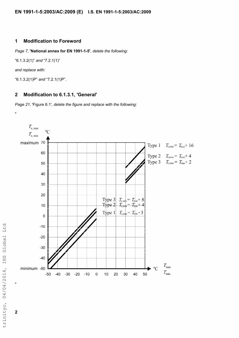
2 Modification to 6.1.3.1, 'General'
Page 21, 'Figure 6.1', delete the figure and replace with the following:
"
"
I.S. EN 1991-1-5:2003/AC:2009
trinityc, 04/04/2014, IHS Global Ltd
EN 1991-1-5:2003/AC:2009 (E)
3
3 Modification to 6.1.3.3, 'Range of uniform bridge temperature component'
Page 22, Paragraph (3), delete 'NOTE 2' and replace with the following:
“
NOTE 2: For bearings and expansion joints the National Annex may specify the maximum expansion range of the uniform bridge temperature component, and the maximum contraction range of the uniform bridge temperature component, if no other provisions are required. The recommended values are ( TN,exp + 20)
oC and ( TN,con. + 20)
oC, respectively. If the temperature at which the bearings and expansion joints, are set is specified, then the
recommended values are ( TN,exp + 10) oC and ( TN,con. + 10)
oC, respectively.
”
4 Modifications to 6.1.4.2, 'Vertical temperature components with non-linear effects (Approach 2)'
Page 25, Paragraph (1), delete 'NOTE 1' and replace with the following:
“
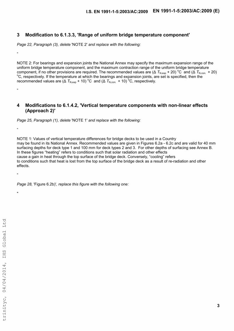
NOTE 1: Values of vertical temperature differences for bridge decks to be used in a Country may be found in its National Annex. Recommended values are given in Figures 6.2a - 6.2c and are valid for 40 mm surfacing depths for deck type 1 and 100 mm for deck types 2 and 3. For other depths of surfacing see Annex B. In these figures “heating” refers to conditions such that solar radiation and other effects cause a gain in heat through the top surface of the bridge deck. Conversely, “cooling” refers to conditions such that heat is lost from the top surface of the bridge deck as a result of re-radiation and other effects.
”
Page 28, 'Figure 6.2b)', replace this figure with the following one:
"
I.S. EN 1991-1-5:2003/AC:2009
trinityc, 04/04/2014, IHS Global Ltd
EN 1991-1-5:2003/AC:2009 (E)
4
"
5 Modification to Subclause A.1, 'General'
Page 36, Paragraph (3), delete the 'NOTE' and replace with the following:
"
NOTE: The value of T0 may be specified in the National annex or in a particular project. If no information is available
T0 may be taken as 10 °C. In case of uncertainty concerning sensitivity of the bridge to T0, it is recommended that a lower and upper bound of an interval expected for T0 are considered.
"
6 Modification to Subclause A.2, 'Maximum and minimum shade air temperature values with an annual probability of being exceeded p other than 0,02'
Page 37, Paragraph (2), delete the sentence just above 'NOTE 1':
“
The ratios Tmax,p/Tmax and Tmin,p/Tmin respectively may then be taken from Figure A.1.
I.S. EN 1991-1-5:2003/AC:2009
trinityc, 04/04/2014, IHS Global Ltd
EN 1991-1-5:2003/AC:2009 (E)
5
”
and replace with:
“
The ratios Tmax,p/Tmax and Tmin,p/Tmin respectively may then be taken from Figure A.1, which is based on the recommended values of k1 – k4 given in NOTE 1.
”
I.S. EN 1991-1-5:2003/AC:2009
trinityc, 04/04/2014, IHS Global Ltd
EN 1991-1-5: 2003 (E)
2
CONTENTS Page
FOREWORD .............................................................................................................. 4
BACKGROUND TO THE EUROCODE PROGRAMME ........................................................... 4STATUS AND FIELD OF APPLICATION OF EUROCODES ..................................................... 5NATIONAL STANDARDS IMPLEMENTING EUROCODES ..................................................... 6LINKS BETWEEN EUROCODES AND PRODUCT HARMONIZED TECHNICAL SPECIFICATIONS
(ENS AND ETAS) ....................................................................................................... 6ADDITIONAL INFORMATION SPECIFIC TO EN 1991-1-5................................................... 6NATIONAL ANNEX FOR EN 1991-1-5 ........................................................................... 7
SECTION 1 GENERAL............................................................................................. 8
1.1 SCOPE ............................................................................................................. 81.2 NORMATIVE REFERENCES .................................................................................. 81.3 ASSUMPTIONS................................................................................................... 81.4 DISTINCTION BETWEEN PRINCIPLES AND APPLICATION RULES ................................ 91.5 DEFINITIONS ..................................................................................................... 91.6 SYMBOLS ....................................................................................................... 10
SECTION 2 CLASSIFICATION OF ACTIONS ....................................................... 13
SECTION 3 DESIGN SITUATIONS........................................................................ 14
SECTION 4 REPRESENTATION OF ACTIONS .................................................... 15
SECTION 5 TEMPERATURE CHANGES IN BUILDINGS..................................... 16
5.1 GENERAL .......................................................................................................... 165.2 DETERMINATION OF TEMPERATURES.................................................................... 165.3 DETERMINATION OF TEMPERATURE PROFILES ....................................................... 17
SECTION 6 TEMPERATURE CHANGES IN BRIDGES ........................................ 19
6.1 BRIDGE DECKS................................................................................................ 196.1.1 Bridge deck types ................................................................................... 196.1.2 Consideration of thermal actions ............................................................... 196.1.3 Uniform temperature component ............................................................... 196.1.4 Temperature difference components ...................................................... 236.1.5 Simultaneity of uniform and temperature difference components........... 296.1.6 Differences in the uniform temperature component between differentstructural elements ............................................................................................. 30
6.2 BRIDGE PIERS ................................................................................................ 306.2.1 Consideration of thermal actions ............................................................ 306.2.2 Temperature differences......................................................................... 30
SECTION 7 TEMPERATURE CHANGES IN INDUSTRIAL CHIMNEYS,PIPELINES, SILOS, TANKS AND COOLING TOWERS......................................... 31
7.1 GENERAL ....................................................................................................... 317.2 TEMPERATURE COMPONENTS........................................................................... 31
7.2.1 Shade air temperature ............................................................................ 317.2.2 Flue gas, heated liquids and heated materials temperature ................... 32
I.S. EN 1991-1-5:2008
trinityc, 04/04/2014, IHS Global Ltd
EN 1991-1-5: 2003 (E)
3
7.2.3 Element temperature .............................................................................. 327.3 CONSIDERATION OF TEMPERATURE COMPONENTS.............................................. 327.4 DETERMINATION OF TEMPERATURE COMPONENTS.............................................. 327.5 VALUES OF TEMPERATURE COMPONENTS (INDICATIVE VALUES) ........................... 337.6 SIMULTANEITY OF TEMPERATURE COMPONENTS................................................. 33
ANNEX A (NORMATIVE) ISOTHERMS OF NATIONAL MINIMUM AND MAXIMUMSHADE AIR TEMPERATURES ............................................................................... 36
A.1 GENERAL ....................................................................................................... 36A.2 MAXIMUM AND MINIMUM SHADE AIR TEMPERATURE VALUES WITH AN ANNUAL
PROBABILITY OF BEING EXCEEDED P OTHER THAN 0,02................................................ 36
ANNEX B (NORMATIVE) TEMPERATURE DIFFERENCES FOR VARIOUSSURFACING DEPTHS............................................................................................. 39
ANNEX C (INFORMATIVE) COEFFICIENTS OF LINEAR EXPANSION ............... 42
ANNEX D (INFORMATIVE) TEMPERATURE PROFILES IN BUILDINGS ANDOTHER CONSTRUCTION WORKS ........................................................................ 44
BIBLIOGRAPHY ...................................................................................................... 46
I.S. EN 1991-1-5:2008
trinityc, 04/04/2014, IHS Global Ltd
EN 1991-1-5: 2003 (E)
4
Foreword
This document (EN 1991-1-5) has been prepared by Technical CommitteeCEN/TC250 "Structural Eurocodes", the secretariat of which is held by BSI.
This European Standard shall be given the status of a national standard, either bypublication of an identical text or by endorsement, at the latest by May 2004, andconflicting national standards shall be withdrawn at the latest by March 2010.
Annexes A and B are normative. Annexes C and D are informative.
This document supersedes ENV 1991-2-5:1997.
According to the CEN/CENELEC Internal Regulations, the national standardsorganizations of the following countries are bound to implement this EuropeanStandard: Austria, Belgium, Czech Republic, Denmark, Finland, France, Germany,Greece, Hungary, Iceland, Ireland, Italy, Luxembourg, Malta, Netherlands, Norway,Portugal, Slovakia, Spain, Sweden, Switzerland and the United Kingdom.
Background to the Eurocode Programme
In 1975, the Commission of the European Communities decided on an actionprogramme in the field of construction, based on article 95 of the treaty. Theobjective of the programme was the elimination of technical obstacles to trade andthe harmonization of technical specifications.
Within this action programme, the Commission took the initiative to establish a set ofharmonised technical rules for the design of construction works which, in a firststage, would serve as an alternative to the national rules in force in the MemberStates and, ultimately, would replace them.
For fifteen years, the Commission, with the help of a Steering Committee withRepresentatives of Member States, conducted the development of the Eurocodesprogramme, which led to the first generation of European codes in the 1980's.
In 1989, the Commission and the Member States of the EU and EFTA decided, onthe basis of an agreement between the Commission and CEN, to transfer thepreparation and the publication of the Eurocodes to CEN through a series ofmandates, in order to provide them with a future status of European Standard (EN).This links de facto the Eurocode with the provisions of all the Council's Directivesand/or Commission's Decisions dealing with European Standards (e.g. the CouncilDirective 89/106/EEC on construction products - CPD - and Council Directives93/37/EEC, 92/50/EEC and 89/440/EEC on public works and services and equivalentEFTA Directives initiated in pursuit of settings up the internal market).
The Structural Eurocode programme comprises the following standards generallyconsisting of a number of Parts:
I.S. EN 1991-1-5:2008
trinityc, 04/04/2014, IHS Global Ltd
EN 1991-1-5: 2003 (E)
5
EN 1990 Eurocode: Basis of Structural DesignEN 1991 Eurocode 1: Actions on structuresEN 1992 Eurocode 2: Design of concrete structuresEN 1993 Eurocode 3: Design of steel structuresEN 1994 Eurocode 4: Design of composite steel and concrete structuresEN 1995 Eurocode 5: Design of timber structuresEN 1996 Eurocode 6: Design of masonry structuresEN 1997 Eurocode 7: Geotechnical designEN 1998 Eurocode 8: Design of structures for earthquake resistanceEN 1999 Eurocode 9: Design of aluminium alloy structures
Eurocode standards recognize the responsibility of regulatory authorities in eachMember State and have safeguarded their right to determine values related toregulatory safety matters at national level where these continue to vary from State toState.
Status and field of application of Eurocodes
The Member States of the EU and EFTA recognize that Eurocodes serve asreference documents for the following purposes:
– as a means of providing compliance of building and civil engineering works withthe essential requirements of Council Directive 89/106/EEC, particularly EssentialRequirement No1 - Mechanical resistance and stability - and EssentialRequirement No2 - Safety in case of fire;
– as a basis for specifying contracts for construction works and related engineeringservices;
– as a framework for drawing up harmonized technical specifications forconstruction products (ENs and ETAs)
The Eurocodes, as far as they concern the construction works themselves, have adirect relationship with the Interpretative Documents referred to in Article 12 of theCPD, although they are of a different nature from harmonized product standards.Therefore, technical aspects arising from the Eurocodes work need to be adequatelyconsidered by CEN Technical Committees and/or EOTA Working Groups working onproduct standards with a view to achieving a full compatibility of these technicalspecifications with the Eurocodes.
The Eurocode standards provide common structural design rules for everyday usefor the design of whole structures and component products of both a traditional andan innovative nature. Unusual forms of construction design conditions are notspecifically covered and additional expert consideration will be required by thedesigner in such cases.
I.S. EN 1991-1-5:2008
trinityc, 04/04/2014, IHS Global Ltd
EN 1991-1-5: 2003 (E)
6
National Standards implementing Eurocodes
The National Standards implementing Eurocodes will comprise the full text of theEurocode (including any annexes), as published by CEN, which may be preceded bya National title page and National foreword, and may be followed by a National annex(informative).
The National annex (informative) may only contain information on those parameterswhich are left open in the Eurocode for national choice, known as NationallyDetermined parameters, to be used for the design of buildings and civil engineeringworks to be constructed in the country concerned, i.e.:
– values and/or classes where alternatives are given in the Eurocode,– values to be used where a symbol only is given in the Eurocode,– country specific data (geographical, climatic, etc.), e.g. snow map,– the procedure to be used where alternative procedures are given in the EN
Eurocode.It may also contain– decisions on the application of informative annexes,– references to non-contradictory complementary information to assist the user to
apply the Eurocode.
Links between Eurocodes and product harmonized technical specifications(ENs and ETAs)
There is a need for consistency between the harmonized technical specifications forconstruction products and the technical rules for works. Furthermore, all theinformation accompanying the CE Marking of the construction products which refer toEurocodes should clearly mention which Nationally Determined Parameters havebeen taken into account.
Additional information specific to EN 1991-1-5
EN 1991-1-5 gives design guidance for thermal actions arising from climatic andoperational conditions on buildings and civil engineering works.
Information on thermal actions induced by fire is given in EN 1991-1-2.
EN 1991-1-5 is intended for clients, designers, contractors and relevant authorities.
EN 1991-1-5 is intended to be used with EN 1990, the other Parts of EN 1991 andEN 1992-1999 for the design of structures.
In the case of bridges, the National annexes specify whether the general non-linearor the simplified linear temperature components should be used in designcalculations.
I.S. EN 1991-1-5:2008
trinityc, 04/04/2014, IHS Global Ltd
EN 1991-1-5: 2003 (E)
7
In the case of chimneys, references should be made to EN 13084-1 for thermalactions from operating processes.
National annex for EN 1991-1-5
This standard gives alternative procedures, values and recommendations for classeswith notes indicating where national choices may have to be made. Therefore theNational Standard implementing EN 1991-1-5 should have a National annexcontaining all Nationally Determined Parameters to be used for the design ofbuildings and civil engineering works to be constructed in the relevant country.
National choice is allowed in EN 1991-1-5 through clauses:
- 5.3(2) (Tables 5.1, 5.2 and 5.3)- 6.1.1 (1)- 6.1.2(2)- 6.1.3.1(4)- 6.1.3.2(1)- 6.1.3.3(3)- 6.1.4(3)- 6.1.4.1(1)- 6.1.4.2(1)- 6.1.4.3(1)- 6.1.4.4(1)- 6.1.5(1)- 6.1.6(1)- 6.2.1(1)P- 6.2.2(1)- 6.2.2(2)- 7.2.1(1)- 7.5(3)- 7.5(4)- A.1(1)- A.1(3)- A.2(2)- B(1) (Tables B.1, B.2 and B.3)
I.S. EN 1991-1-5:2008
trinityc, 04/04/2014, IHS Global Ltd
EN 1991-1-5: 2003 (E)
8
Section 1 General
1.1 Scope
(1) EN 1991-1-5 gives principles and rules for calculating thermal actions onbuildings, bridges and other structures including their structural elements. Principlesneeded for cladding and other appendages of buildings are also provided.
(2) This Part describes the changes in the temperature of structural elements.Characteristic values of thermal actions are presented for use in the design ofstructures which are exposed to daily and seasonal climatic changes. Structures notso exposed may not need to be considered for thermal actions.
(3) Structures in which thermal actions are mainly a function of their use (e.g. coolingtowers, silos, tanks, warm and cold storage facilities, hot and cold services etc) aretreated in Section 7. Chimneys are treated in EN 13084-1.
1.2 Normative references
This European Standard incorporates, by dated or undated reference, provisionsfrom other publications. These normative references are cited at the appropriateplaces in the text and the publications are listed hereafter. For dated references,subsequent amendments to or revisions of any of these publications apply to thisEuropean Standard only when incorporated in it by amendment or revision. Forundated references the latest edition of the publication referred to applies (includingamendments).
EN 1990:2002 Eurocode: Basis of structural design
prEN 1991-1-6 Eurocode 1: Actions on structuresPart 1.6: General actions - Actions during execution
EN 13084-1 Free-standing industrial chimneysPart 1: General requirements
ISO 2394 General principles on reliability for structures
ISO 3898 Bases of design of structures - Notations. General symbols
ISO 8930 General principles on reliability for structures. List of equivalent terms
1.3 Assumptions
(1)P The general assumptions of EN 1990 also apply to this Part.
I.S. EN 1991-1-5:2008
trinityc, 04/04/2014, IHS Global Ltd
EN 1991-1-5: 2003 (E)
9
1.4 Distinction between principles and application rules
(1)P The rules in EN 1990:2002, 1.4 also apply to this Part.
1.5 Terms and definitions
For the purposes of this European Standard, the definitions given in EN 1990,ISO 2394, ISO 3898 and ISO 8930 and the following apply.
1.5.1thermal actionsthermal actions on a structure or a structural element are those actions that arisefrom the changes of temperature fields within a specified time interval
1.5.2shade air temperaturethe shade air temperature is the temperature measured by thermometers placed in awhite painted louvred wooden box known as a “Stevenson screen”
1.5.3maximum shade air temperature Tmax
value of maximum shade air temperature with an annual probability of beingexceeded of 0,02 (equivalent to a mean return period of 50 years), based on themaximum hourly values recorded
1.5.4minimum shade air temperature Tmin
value of minimum shade air temperature with an annual probability of beingexceeded of 0,02 (equivalent to a mean return period of 50 years), based on theminimum hourly values recorded
1.5.5initial temperature T0
the temperature of a structural element at the relevant stage of its restraint(completion)
1.5.6claddingthe part of the building which provides a weatherproof membrane. Generally claddingwill only carry self weight and/or wind actions
1.5.7uniform temperature componentthe temperature, constant over the cross section, which governs the expansion orcontraction of an element or structure (for bridges this is often defined as the“effective” temperature, but the term “uniform” has been adopted in this part)
I.S. EN 1991-1-5:2008
trinityc, 04/04/2014, IHS Global Ltd
EN 1991-1-5: 2003 (E)
10
1.5.8temperature difference componentthe part of a temperature profile in a structural element representing the temperaturedifference between the outer face of the element and any in-depth point
1.6 Symbols
(1) For the purposes of this Part of Eurocode 1, the following symbols apply.
NOTE: The notation used is based on ISO 3898
(2) A basic list of notations is provided in EN 1990, and the additional notations beloware specific to this Part.
Latin upper case letters
R thermal resistance of structural element
Rin thermal resistance at the inner surface
Rout thermal resistance at the outer surface
Tmax maximum shade air temperature with an annual probability of being
exceeded of 0,02 (equivalent to a mean return period of 50 years)
Tmin minimum shade air temperature with an annual probability of being
exceeded of 0,02 (equivalent to a mean return period of 50 years)
Tmax,p maximum shade air temperature with an annual probability of being
exceeded p (equivalent to a mean return period of 1/p)
Tmin,p minimum shade air temperature with an annual probability of being
exceeded p (equivalent to a mean return period of 1/p)
Te.max maximum uniform bridge temperature component
Te.min minimum uniform bridge temperature component
T0 initial temperature when structural element is restrained
Tin air temperature of the inner environment
Tout temperature of the outer environment
!T1, !T2, values of heating (cooling) temperature differences
!T3, ! T4
I.S. EN 1991-1-5:2008
trinityc, 04/04/2014, IHS Global Ltd
EN 1991-1-5: 2003 (E)
11
!TU uniform temperature component
!TN, exp maximum expansion range of uniform bridge temperature component
(Te.max " T0)
!TN, con maximum contraction range of uniform bridge temperature component
(T0 " Te.min)
!TN overall range of uniform bridge temperature component
!TM linear temperature difference component
!TM,heat linear temperature difference component (heating)
!TM,cool linear temperature difference component (cooling)
!TE non-linear part of the temperature difference component
!T sum of linear temperature difference component and non-linear part of
the temperature difference component
!Tp temperature difference between different parts of a structure given by
the difference of average temperatures of these parts
Latin lower case letters
h height of the cross-section
k1,k2 coefficients for calculation of maximum (minimum) shade airk3,k4 temperature with an annual probability of being exceeded, p, other than
0,02
ksur surfacing factor for linear temperature difference component
p annual probability of maximum (minimum) shade air temperature beingexceeded (equivalent to a mean return period of 1/p years)
u,c mode and scale parameter of annual maximum (minimum)shade air temperature distribution
Greek lower case letters
#T coefficient of linear expansion (1/°C)
$ thermal conductivity
I.S. EN 1991-1-5:2008
trinityc, 04/04/2014, IHS Global Ltd
EN 1991-1-5: 2003 (E)
12
!N reduction factor of uniform temperature component for combinationwith temperature difference component
!M reduction factor of temperature difference component for combinationwith uniform temperature component
I.S. EN 1991-1-5:2008
trinityc, 04/04/2014, IHS Global Ltd
EN 1991-1-5: 2003 (E)
13
Section 2 Classification of actions
(1)P Thermal actions shall be classified as variable and indirect actions, see EN1990:2002, 1.5.3 and 4.1.1.
(2) All values of thermal actions given in this Part are characteristic values unless it isstated otherwise.
(3) Characteristic values of thermal actions as given in this Part are values with anannual probability of being exceeded of 0,02, unless otherwise stated, e.g. fortransient design situations.
NOTE: For transient design situations, the related values of thermal actions may be derivedusing the calculation method given in A.2.
I.S. EN 1991-1-5:2008
trinityc, 04/04/2014, IHS Global Ltd
EN 1991-1-5: 2003 (E)
14
Section 3 Design situations
(1)P Thermal actions shall be determined for each relevant design situation identifiedin accordance with EN 1990.
NOTE: Structures not exposed to daily and seasonal climatic and operational temperaturechanges may not need to be considered for thermal actions.
(2)P The elements of loadbearing structures shall be checked to ensure that thermalmovement will not cause overstressing of the structure, either by the provision ofmovement joints or by including the effects in the design.
I.S. EN 1991-1-5:2008
trinityc, 04/04/2014, IHS Global Ltd
EN 1991-1-5: 2003 (E)
15
Section 4 Representation of actions
(1) Daily and seasonal changes in shade air temperature, solar radiation, re-radiation, etc., will result in variations of the temperature distribution within individualelements of a structure.
(2) The magnitude of the thermal effects will be dependent on local climaticconditions, together with the orientation of the structure, its overall mass, finishes(e.g. cladding in buildings), and in the case of building structures, heating andventilation regimes and thermal insulation.
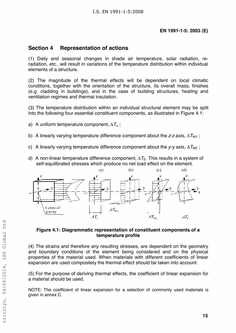
(3) The temperature distribution within an individual structural element may be splitinto the following four essential constituent components, as illustrated in Figure 4.1:
a) A uniform temperature component, !Tu ;
b) A linearly varying temperature difference component about the z-z axis, !TMY ;
c) A linearly varying temperature difference component about the y-y axis, !TMZ ;
d) A non-linear temperature difference component, !TE. This results in a system ofself-equilibrated stresses which produce no net load effect on the element.
Figure 4.1: Diagrammatic representation of constituent components of atemperature profile
(4) The strains and therefore any resulting stresses, are dependent on the geometryand boundary conditions of the element being considered and on the physicalproperties of the material used. When materials with different coefficients of linearexpansion are used compositely the thermal effect should be taken into account.
(5) For the purpose of deriving thermal effects, the coefficient of linear expansion fora material should be used.
NOTE: The coefficient of linear expansion for a selection of commonly used materials isgiven in annex C.
I.S. EN 1991-1-5:2008
trinityc, 04/04/2014, IHS Global Ltd
EN 1991-1-5: 2003 (E)
16
Section 5 Temperature changes in buildings
5.1 General
(1)P Thermal actions on buildings due to climatic and operational temperaturechanges shall be considered in the design of buildings where there is a possibility ofthe ultimate or serviceability limit states being exceeded due to thermal movementand/or stresses.
NOTE 1: Volume changes and/or stresses due to temperature changes may also beinfluenced by:
a) shading of adjacent buildings,
b) use of different materials with different thermal expansion coefficients and heat transfer,
c) use of different shapes of cross-section with different uniform temperature.
NOTE 2: Moisture and other environmental factors may also affect the volume changes ofelements.
5.2 Determination of temperatures
(1) Thermal actions on buildings due to climatic and operational temperaturechanges should be determined in accordance with the principles and rules providedin this Section taking into account national (regional) data and experience.
(2)P The climatic effects shall be determined by considering the variation of shade airtemperature and solar radiation. Operational effects (due to heating, technological orindustrial processes) shall be considered in accordance with the particular project.
(3)P In accordance with the temperature components given in Section 4, climatic andoperational thermal actions on a structural element shall be specified using thefollowing basic quantities:
a) A uniform temperature component !Tu given by the difference between the
average temperature T of an element and its initial temperature T0.
b) A linearly varying temperature component given by the difference !TM between
the temperatures on the outer and inner surfaces of a cross section, or on thesurfaces of individual layers.
c) A temperature difference !Tp of different parts of a structure given by the
difference of average temperatures of these parts.
NOTE: Values of !TM
and !Tp may be provided for the particular project.
(4) In addition to !Tu, !T
M and !T
p, local effects of thermal actions should be
considered where relevant (e.g. at supports or fixings of structural and cladding
I.S. EN 1991-1-5:2008
trinityc, 04/04/2014, IHS Global Ltd
EN 1991-1-5: 2003 (E)
17
elements). Adequate representation of thermal actions should be defined taking intoaccount the location of the building and structural detailing.
(5) The uniform temperature component of a structural element !Tu is defined as:
!Tu = T – T
0(5.1)
where:
T is an average temperature of a structural element due to climatic temperaturesin winter or summer season and due to operational temperatures.
(6) The quantities !Tu, !TM, !Tp, and T should be determined in accordance with theprinciples provided in 5.3 using regional data. When regional data are not available,the rules in 5.3 may be applied.
5.3 Determination of temperature profiles
(1) The temperature T in Expression (5.1) should be determined as the averagetemperature of a structural element in winter or summer using a temperature profile.In the case of a sandwich element T is the average temperature of a particular layer.
NOTE 1: Methods of the thermal transmission theory are indicated in annex D.
NOTE 2: When elements of one layer are considered and when the environmental conditionson both sides are similar, T may be approximately determined as the average of inner andouter environment temperature T
in and T
out.
(2) The temperature of the inner environment, Tin , should be determined in
accordance with Table 5.1. The temperature of the outer environment, Tout
, should
be determined in accordance with:
a) Table 5.2 for parts located above ground level,
b) Table 5.3 for underground parts.
NOTE: The temperatures Tout
for the summer season as indicated in Table 5.2 are
dependent on the surface absorptivity and its orientation:
– the maximum is usually reached for surfaces facing the west, south-west or for horizontalsurfaces,
– the minimum (in 0C about half of the maximum) for surfaces facing the north.
I.S. EN 1991-1-5:2008
trinityc, 04/04/2014, IHS Global Ltd
EN 1991-1-5: 2003 (E)
18
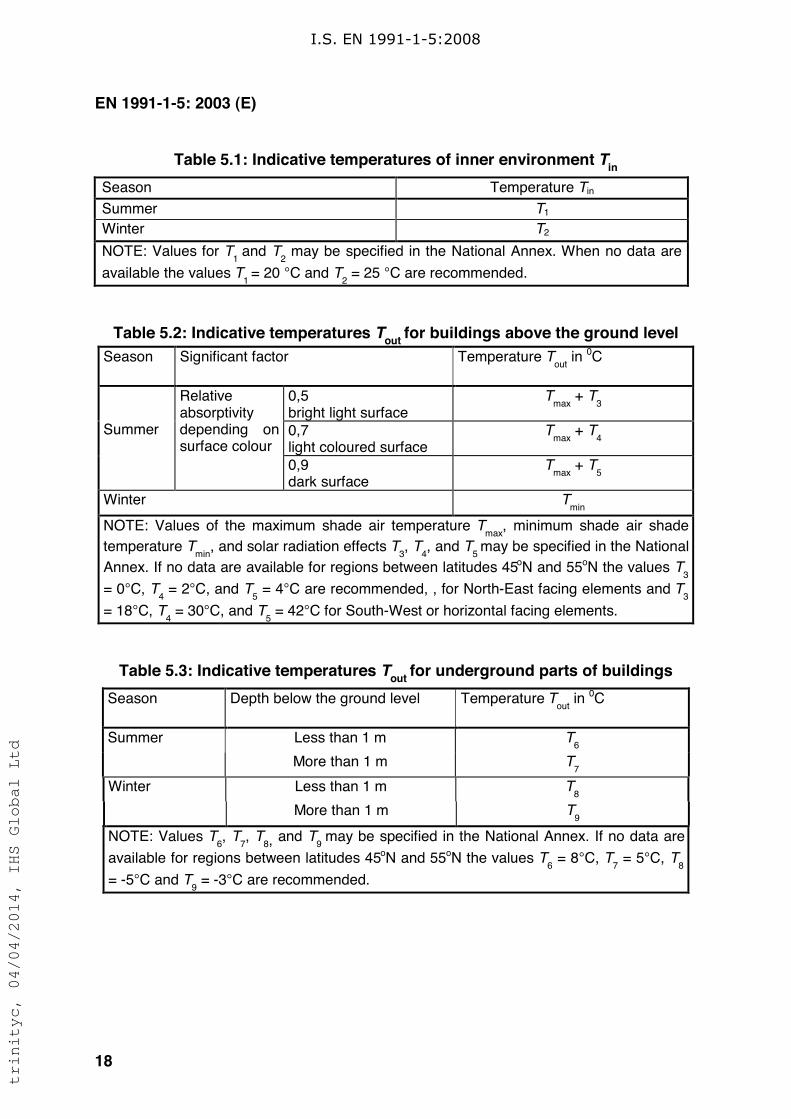
Table 5.1: Indicative temperatures of inner environment Tin
Season Temperature Tin
Summer T1
Winter T2
NOTE: Values for T1 and T
2 may be specified in the National Annex. When no data are
available the values T1 = 20 °C and T
2 = 25 °C are recommended.
Table 5.2: Indicative temperatures Tout
for buildings above the ground level
Season Significant factor Temperature Tout
in 0C
0,5bright light surface
Tmax
+ T3
0,7light coloured surface
Tmax
+ T4
Summer
Relativeabsorptivitydepending onsurface colour
0,9dark surface
Tmax
+ T5
Winter Tmin
NOTE: Values of the maximum shade air temperature Tmax
, minimum shade air shade
temperature Tmin
, and solar radiation effects T3, T
4, and T
5 may be specified in the National
Annex. If no data are available for regions between latitudes 45oN and 55oN the values T3
= 0°C, T4 = 2°C, and T
5 = 4°C are recommended, , for North-East facing elements and T
3
= 18°C, T4 = 30°C, and T
5 = 42°C for South-West or horizontal facing elements.
Table 5.3: Indicative temperatures Tout
for underground parts of buildings
Season Depth below the ground level Temperature Tout
in 0C
Less than 1 m T6
Summer
More than 1 m T7
Less than 1 m T8
Winter
More than 1 m T9
NOTE: Values T6, T
7, T
8, and T9 may be specified in the National Annex. If no data are
available for regions between latitudes 45oN and 55oN the values T6 = 8°C, T
7 = 5°C, T
8
= -5°C and T9 = -3°C are recommended.
I.S. EN 1991-1-5:2008
trinityc, 04/04/2014, IHS Global Ltd
EN 1991-1-5: 2003 (E)
19
Section 6 Temperature changes in bridges
6.1 Bridge decks
6.1.1 Bridge deck types
(1) For the purposes of this Part, bridge decks are grouped as follows:
Type 1 Steel deck: - steel box girder- steel truss or plate girder
Type 2 Composite deck
Type 3 Concrete deck: - concrete slab- concrete beam- concrete box girder
NOTE 1: See also Figure 6.2.
NOTE 2: The National Annex may specify values of the uniform temperature component andthe temperature difference component for other types of bridges.
6.1.2 Consideration of thermal actions
(1) Representative values of thermal actions should be assessed by the uniformtemperature component (see 6.1.3) and the temperature difference components (see6.1.4).
(2) The vertical temperature difference component given in 6.1.4 should generallyinclude the non-linear component, see 4(3). Either Approach 1 (see 6.1.4.1) orApproach 2 (see 6.1.4.2) should be used.
NOTE: The selection of the approach to be used in a Country may be found in its NationalAnnex.
(3) Where a horizontal temperature difference needs to be considered a lineartemperature difference component may be assumed in the absence of otherinformation (see 6.1.4.3).
6.1.3 Uniform temperature component
6.1.3.1 General
(1) The uniform temperature component depends on the minimum and maximumtemperature which a bridge will achieve. This results in a range of uniform
I.S. EN 1991-1-5:2008
trinityc, 04/04/2014, IHS Global Ltd
EN 1991-1-5: 2003 (E)
20
temperature changes which, in an unrestrained structure would result in a change inelement length.
(2) The following effects should be taken into account where relevant:
– Restraint of associated expansion or contraction due to the type of construction(e.g. portal frame, arch, elastomeric bearings);
– Friction at roller or sliding bearings;
– Non-linear geometric effects (2nd order effects);
– For railway bridges the interaction effects between the track and the bridge dueto the variation of the temperature of the deck and of the rails may inducesupplementary horizontal forces in the bearings (and supplementary forces in therails).
NOTE: For more information, see EN 1991-2.
(3)P Minimum shade air temperature (Tmin) and maximum shade air temperature(Tmax) for the site shall be derived from isotherms in accordance with 6.1.3.2.
(4) The minimum and maximum uniform bridge temperature components Te.min andTe.max should be determined.
NOTE: The National Annex may specify Te.min and Te.max. Figure 6.1 below givesrecommended values.
I.S. EN 1991-1-5:2008
trinityc, 04/04/2014, IHS Global Ltd
EN 1991-1-5: 2003 (E)
21
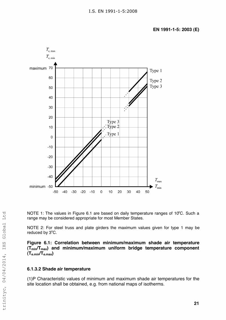
NOTE 1: The values in Figure 6.1 are based on daily temperature ranges of 10oC. Such arange may be considered appropriate for most Member States.
NOTE 2: For steel truss and plate girders the maximum values given for type 1 may bereduced by 3oC.
Figure 6.1: Correlation between minimum/maximum shade air temperature(Tmin/Tmax) and minimum/maximum uniform bridge temperature component(Te.min/Te.max)
6.1.3.2 Shade air temperature
(1)P Characteristic values of minimum and maximum shade air temperatures for thesite location shall be obtained, e.g. from national maps of isotherms.
I.S. EN 1991-1-5:2008
trinityc, 04/04/2014, IHS Global Ltd
EN 1991-1-5: 2003 (E)
22
NOTE: Information (e.g. maps of isotherms) on minimum and maximum shade airtemperatures to be used in a Country may be found in its National Annex.
(2) These characteristic values should represent shade air temperatures for meansea level in open country with an annual probability of being exceeded of 0,02. Forother annual probabilities of being exceeded (p other than 0,02), height above sealevel and local conditions (e.g. frost pockets) the values should be adjusted inaccordance with annex A.
(3) Where an annual probability of being exceeded of 0,02 is deemed inappropriate,the minimum shade air temperatures and the maximum shade air temperaturesshould be modified in accordance with annex A.
6.1.3.3 Range of uniform bridge temperature component
(1)P The values of minimum and maximum uniform bridge temperature componentsfor restraining forces shall be derived from the minimum (Tmin) and maximum (Tmax)shade air temperatures (see 6.1.3.1(3) and 6.1.3.1(4)).
(2) The initial bridge temperature To at the time that the structure is restrained may betaken from annex A for calculating contraction down to the minimum uniform bridgetemperature component and expansion up to the maximum uniform bridgetemperature component.
(3) Thus the characteristic value of the maximum contraction range of the uniform
bridge temperature component, !TN,con should be taken as
!TN,con = T0 - Te.min (6.1)
and the characteristic value of the maximum expansion range of the uniform bridge
temperature component, !TN,exp should be taken as
!TN,exp = Te .max - To (6.2)
NOTE 1: The overall range of the uniform bridge temperature component is
!TN = Te.max - Te.min
NOTE 2: For bearings and expansion joints the National Annex may specify the maximumexpansion range of the uniform bridge temperature component, and the maximumcontraction range of the uniform bridge temperature component, if no other provisions are
required. The recommended values are (!TN,exp + 20)oC and (!TN,con + 20)oC. If thetemperature at which the bearings and expansion joints are set is specified, then the
recommended values are (!TN,exp + 10)oC and (!TN,con + 10)oC.
NOTE 3: For the design of bearings and expansion joints, the values of the coefficient ofexpansion given in annex C, Table C.1 may be modified if alternative values have beenverified by tests or more detailed studies.
I.S. EN 1991-1-5:2008
trinityc, 04/04/2014, IHS Global Ltd
EN 1991-1-5: 2003 (E)
23
6.1.4 Temperature difference components
(1) Over a prescribed time period heating and cooling of a bridge deck's uppersurface will result in a maximum heating (top surface warmer) and a maximumcooling (bottom surface warmer) temperature variation.
(2) The vertical temperature difference may produce effects within a structure due to:
– Restraint of free curvature due to the form of the structure (e.g. portal frame,continuous beams etc.);
– Friction at rotational bearings;
– Non-linear geometric effects (2nd order effects).
(3) In the case of cantilever construction an initial temperature difference may needto be taken into account at the closure of the cantilever.
NOTE: Values of the initial temperature difference may be specified in the National Annex.
6.1.4.1 Vertical linear component (Approach 1)
(1) The effect of vertical temperature differences should be considered by using anequivalent linear temperature difference component (see 6.1.2(2))with !TM,heat and!TM,cool. These values should be applied between the top and the bottom of the bridgedeck.
NOTE: Values of !TM,heat and !TM,cool to be used in a Country may be found in its National
Annex. Recommended values for !TM,heat and !TM,cool are given in Table 6.1.
I.S. EN 1991-1-5:2008
trinityc, 04/04/2014, IHS Global Ltd
EN 1991-1-5: 2003 (E)
24
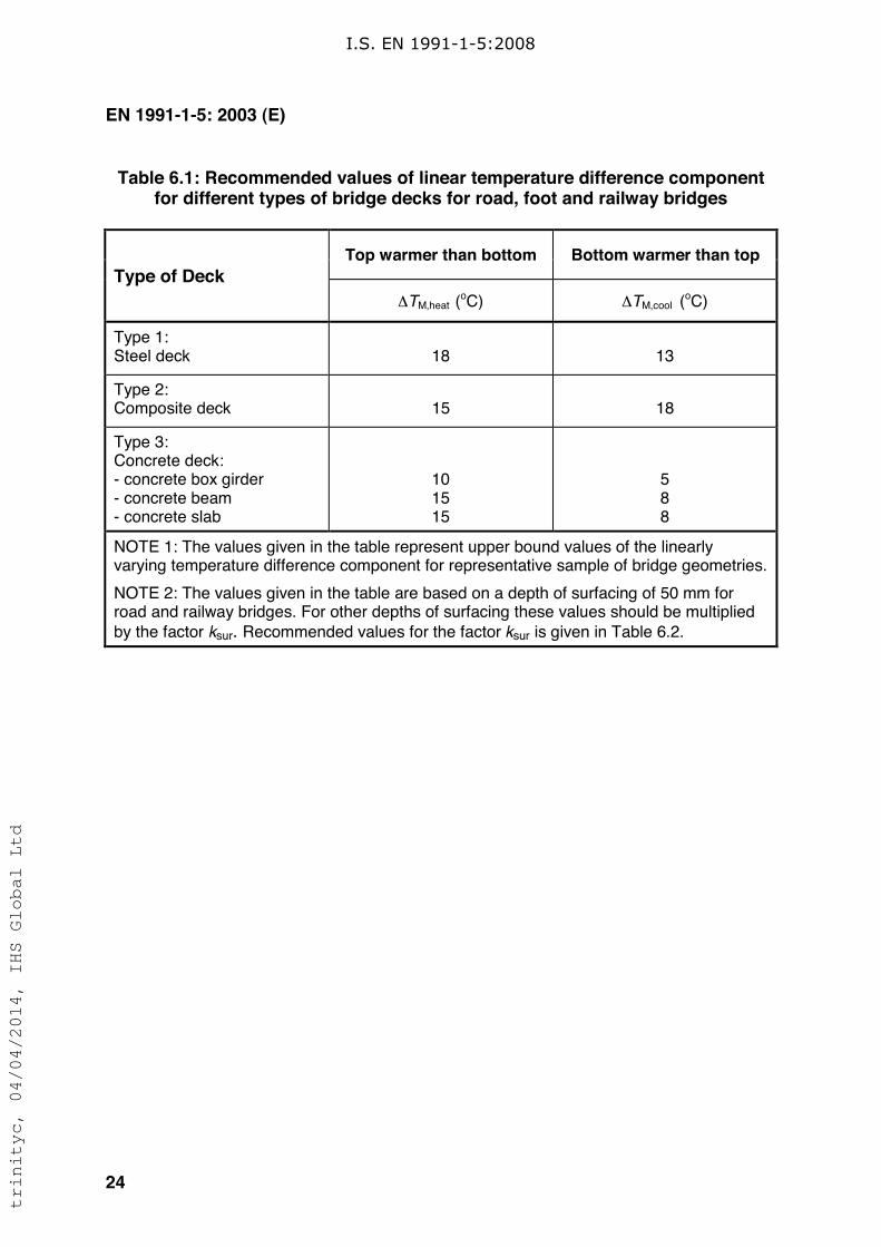
Table 6.1: Recommended values of linear temperature difference componentfor different types of bridge decks for road, foot and railway bridges
Top warmer than bottom Bottom warmer than top
Type of Deck
!TM,heat (oC) !TM,cool (
oC)
Type 1:Steel deck 18 13
Type 2:Composite deck 15 18
Type 3:Concrete deck:- concrete box girder- concrete beam- concrete slab
101515
588
NOTE 1: The values given in the table represent upper bound values of the linearlyvarying temperature difference component for representative sample of bridge geometries.
NOTE 2: The values given in the table are based on a depth of surfacing of 50 mm forroad and railway bridges. For other depths of surfacing these values should be multiplied
by the factor ksur. Recommended values for the factor ksur is given in Table 6.2.
I.S. EN 1991-1-5:2008
trinityc, 04/04/2014, IHS Global Ltd
EN 1991-1-5: 2003 (E)
25
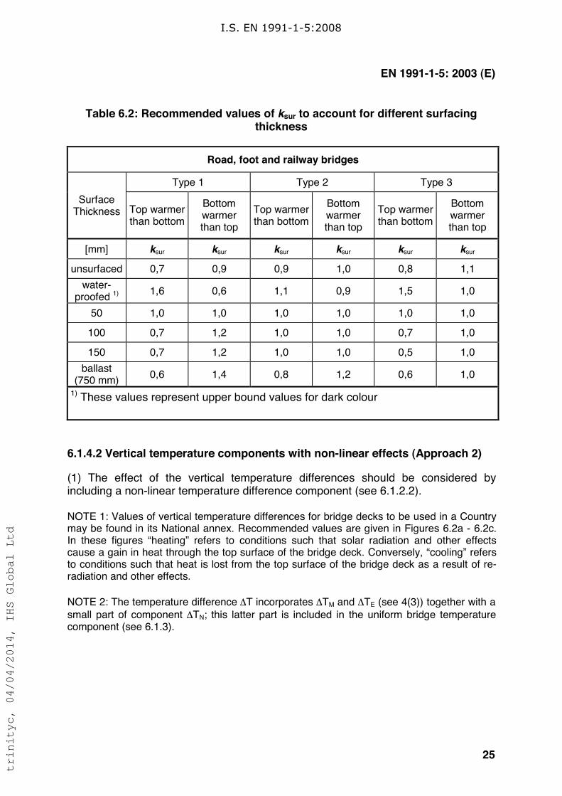
Table 6.2: Recommended values of ksur to account for different surfacingthickness
Road, foot and railway bridges
Type 1 Type 2 Type 3
SurfaceThickness Top warmer
than bottom
Bottomwarmerthan top
Top warmerthan bottom
Bottomwarmerthan top
Top warmerthan bottom
Bottomwarmerthan top
[mm] ksur ksur ksur ksur ksur ksur
unsurfaced 0,7 0,9 0,9 1,0 0,8 1,1
water-proofed 1) 1,6 0,6 1,1 0,9 1,5 1,0
50 1,0 1,0 1,0 1,0 1,0 1,0
100 0,7 1,2 1,0 1,0 0,7 1,0
150 0,7 1,2 1,0 1,0 0,5 1,0
ballast(750 mm)
0,6 1,4 0,8 1,2 0,6 1,0
1) These values represent upper bound values for dark colour
6.1.4.2 Vertical temperature components with non-linear effects (Approach 2)
(1) The effect of the vertical temperature differences should be considered byincluding a non-linear temperature difference component (see 6.1.2.2).
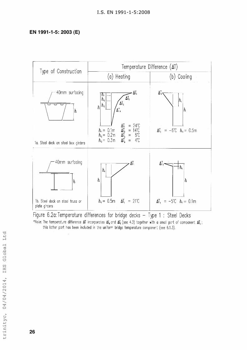
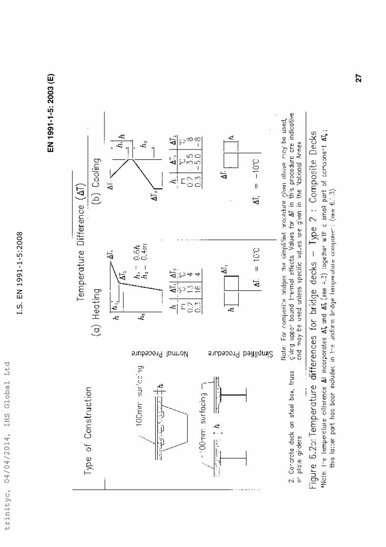
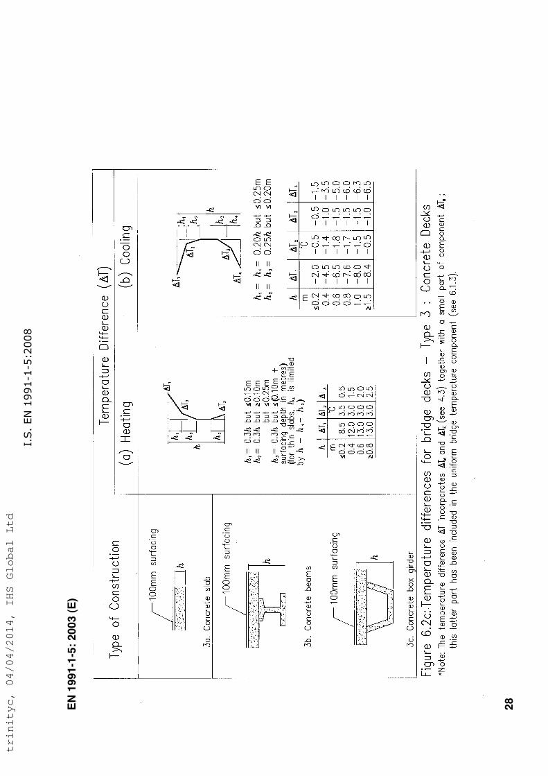
NOTE 1: Values of vertical temperature differences for bridge decks to be used in a Countrymay be found in its National annex. Recommended values are given in Figures 6.2a - 6.2c.In these figures “heating” refers to conditions such that solar radiation and other effectscause a gain in heat through the top surface of the bridge deck. Conversely, “cooling” refersto conditions such that heat is lost from the top surface of the bridge deck as a result of re-radiation and other effects.
NOTE 2: The temperature difference !T incorporates !TM and !TE (see 4(3)) together with a
small part of component !TN; this latter part is included in the uniform bridge temperaturecomponent (see 6.1.3).
I.S. EN 1991-1-5:2008
trinityc, 04/04/2014, IHS Global Ltd
EN 1991-1-5: 2003 (E)
26
I.S. EN 1991-1-5:2008
trinityc, 04/04/2014, IHS Global Ltd
EN
19
91
-1-5
: 20
03 (
E)
27
I.S
. EN
1991-1-5:2008
trinityc, 04/04/2014, IHS Global Ltd
EN
19
91
-1-5
: 20
03 (
E)
28
I.S
. EN
1991-1-5:2008
trinityc, 04/04/2014, IHS Global Ltd
EN 1991-1-5: 2003 (E)
29
6.1.4.3 Horizontal components
(1) In general, the temperature difference component need only be considered in thevertical direction. In particular cases however (for example when the orientation orconfiguration of the bridge results in one side being more highly exposed to sunlightthan the other side), a horizontal temperature difference component should beconsidered.
NOTE: The National annex may specify numerical values for the temperature difference. Ifno other information is available and no indications of higher values exist, 5oC may berecommended as a linear temperature difference between the outer edges of the bridgeindependent of the width of the bridge.
6.1.4.4 Temperature difference components within walls of concrete boxgirders
(1) Care should be exercised in the design of large concrete box girder bridgeswhere significant temperature differences can occur between the inner and outer webwalls of such structures.
NOTE: The National annex may specify numerical values for the temperature difference. Therecommended value for a linear temperature difference is 150C.
6.1.5 Simultaneity of uniform and temperature difference components
(1) If it is necessary to take into account both the temperature difference !TM,heat (or
!TM,cool) and the maximum range of uniform bridge temperature component !TN,exp
(or !TN,con) assuming simultaneity (e.g. in case of frame structures) the followingexpression may be used (which should be interpreted as load combinations):
!TM,heat (or !TM,cool) + "N !TN,exp (or !TN,con) (6.3)or
"M !TM,heat (or !TM,cool) + !TN,exp (or !TN,con) (6.4)
where the most adverse effect should be chosen.
NOTE 1: The National annex may specify numerical values of "N and "M. If no other
information is available, the recommended values for "N and "M are:
"N = 0,35
"M = 0,75.
NOTE 2: Where both linear and non-linear vertical temperature differences are used (see
6.1.4.2) !TM should be replaced by !T which includes !TM and !TE .
I.S. EN 1991-1-5:2008
trinityc, 04/04/2014, IHS Global Ltd
EN 1991-1-5: 2003 (E)
30
6.1.6 Differences in the uniform temperature component between differentstructural elements
(1) In structures where differences in the uniform temperature component betweendifferent element types may cause adverse load effects, these effects should betaken into account.
NOTE: The National annex may give values for the differences in the uniform temperaturecomponent. Recommended values are:
– 15oC between main structural elements (e.g. tie and arch); and
– 10oC and 20oC for light and dark colour respectively between suspension/staycables and deck (or tower).
(2) These effects should be considered in addition to the effects resulting from auniform temperature component in all elements, determined from 6.1.3.
6.2 Bridge Piers
6.2.1 Consideration of thermal actions
(1)P Temperature differences between the outer faces of bridge piers, hollow orsolid, shall be considered in the design.
NOTE: The design procedure to be used in a Country may be found in its National annex. Ifno procedure is given an equivalent linear temperature difference may be assumed.
(2) Overall temperature effects of piers should be considered, when these can lead torestraining forces or movements in the surrounding structures.
6.2.2 Temperature differences
(1) For concrete piers (hollow or solid), the linear temperature differences betweenopposite outer faces should be taken into account.
NOTE: The National annex may specify values for linear temperature differences. In the
absence of detailed information the recommended value is 5oC.
(2) For walls the linear temperature differences between the inner and outer facesshould be taken into account.
NOTE 1: The National annex may specify values for linear temperature differences. In the
absence of detailed information the recommended value is 15oC.
NOTE 2: When considering temperature differences for metal columns specialist advice mayneed to be obtained.
I.S. EN 1991-1-5:2008
trinityc, 04/04/2014, IHS Global Ltd
EN 1991-1-5: 2003 (E)
31
Section 7 Temperature changes in industrial chimneys, pipelines,silos, tanks and cooling towers
7.1 General
(1)P Structures which are in contact with gas flow, liquids or material with differenttemperatures (e.g. industrial chimneys, pipelines, silos, tanks and cooling towers)shall be designed where relevant for the following conditions:
– thermal actions from climatic effects due to the variation of shade air temperatureand solar radiation,
– temperature distribution for normal and abnormal process conditions,
– effects arising from interaction between the structure and its contents duringthermal changes (e.g. shrinkage of the structure against stiff solid contents orexpansion of solid contents during heating or cooling).
NOTE 1: Values of the operating process temperature may be obtained from the particularproject.
NOTE 2: For the operating process temperatures of chimneys see EN 13084-1.
NOTE 3: Containment structures may be subjected to thermally induced changes in shapearising from heating/cooling effects of either the contents or their surrounding externalenvironment.
NOTE 4: No further guidance on the effect of shrinkage against stiff solid contents is given inthis standard. See EN 1991-4 for this effect in silos.
7.2 Temperature components
7.2.1 Shade air temperature
(1)P Values of minimum and maximum shade air temperatures for the site locationshall be obtained, e.g. from national maps of isotherms.
NOTE: Information (e.g. maps of isotherms) on minimum and maximum shade airtemperatures to be used in a Country may be found in its National annex.
(2) These shade air temperatures should be appropriate to mean sea level in opencountry with an annual probability of being exceeded of 0,02. annex A includesadjustments for other values of probabilities, height above sea level and localconditions e.g. frost pockets.
(3) For circumstances where an annual probability of being exceeded of 0,02 isdeemed inappropriate, e.g. during execution (see EN1991-1-6 “Actions during
I.S. EN 1991-1-5:2008
trinityc, 04/04/2014, IHS Global Ltd
EN 1991-1-5: 2003 (E)
32
execution”), the values of minimum (or maximum) shade air temperature should bemodified in accordance with annex A.
7.2.2 Flue gas, heated liquids and heated materials temperature
(1) Values of maximum and minimum flue gas, liquids and materials with differenttemperatures should be specified for the particular project.
7.2.3 Element temperature
(1) The derivation of values of element temperature will depend on the materialconfiguration, orientation and location of the element and will be a function of themaximum and minimum shade air temperature, the external solar radiation, and theinternal operating temperature.
NOTE: General rules for the determination of temperature profiles are given in annex D. Seealso 7.5.
7.3 Consideration of temperature components
(1)P Both the uniform temperature component of the temperature distribution (seeFigure 4.1 (a)) and the linearly varying temperature difference component (seeFigure 4.1 (b)) shall be considered for each layer.
(2)P The effect of solar radiation shall be considered in the design.
(3) This effect may be approximated by a step temperature distribution round thestructure’s circumference.
(4)P The uniform temperature component and the linearly varying temperaturedifference component due to process temperature shall be considered for each layer.
7.4 Determination of temperature components
(1)P The uniform and linearly varying temperature components shall be determinedtaking into account climatic effects and operating conditions.
(2) If specific information on how the element temperature can be correlated with thesolar radiation and shade air temperature is available in order to provide values ofelement temperature, such information should be used to provide design values.
(3)P Values of the uniform temperature component from heated gas flow, liquids andheated materials shall be taken from the project specification. As far as chimneys areconcerned these values shall be obtained from EN 13084-1.
(4)P The linearly varying temperature difference component in the wall or its layersshall be taken as arising from the difference between the minimum (or maximum)
I.S. EN 1991-1-5:2008
trinityc, 04/04/2014, IHS Global Ltd
EN 1991-1-5: 2003 (E)
33
shade air temperature on the outer face and the value of the liquid or gastemperature on the inner face, taking into account insulation effects.
NOTE: Temperature profiles may be determined using annex D.
7.5 Values of temperature components (indicative values)
(1) In the absence of any specific information on characteristic values of the elementtemperature, the following indicative values may be used.
NOTE: These values may be checked against any available data to ensure that they arelikely to be upper bound values, for the location and the type of element under consideration.
(2) Values of the maximum and minimum uniform temperature component should betaken as those of the maximum and minimum shade air temperature (see 7.2.1).
(3) For concrete pipelines the linear temperature difference component between theinner and outer faces of the wall should be considered.
NOTE 1: The National annex may specify the values for the linear temperature differencecomponent. The recommended value is 15oC.
NOTE 2: For chimneys see EN 13084-1.
(4) For concrete pipelines a stepped temperature component round thecircumference (causing both overall and local thermal effects) should be consideredon the basis that one quadrant of its circumference has a mean temperature higherthan that of the remainder of the circumference.
NOTE: The value of the difference of temperature may be given in the National annex. Therecommended value is 15oC.
(5) When considering steel pipelines, the linear temperature difference componentand stepped temperature component round the structure’s circumference should becalculated taking into account the operating conditions as set down in the particularproject.
NOTE: The rules for steel chimneys are given in EN 13084-1.
7.6 Simultaneity of temperature components
(1) When considering thermal actions due to climatic effects only, the followingcomponents take account of simultaneity:
a) uniform temperature component (see 7.5 (2) and Figure 7.1 (a));
b) stepped temperature component (see 7.5 (4) and Figure 7.1 (b));
I.S. EN 1991-1-5:2008
trinityc, 04/04/2014, IHS Global Ltd
EN 1991-1-5: 2003 (E)
34
c) the linear temperature difference component between the inner and the outerfaces of the wall (see 7.5 (3) and Figure 7.1 (c)).
(2) When considering a combination of thermal actions due to climatic effects withthose due to process effects (heated gas flow, liquids or heated materials) thefollowing components should be combined:
– uniform temperature component (see 7.4 (3));
– linear temperature difference component (see 7.4 (4));
– stepped component (see 7.5 (4)).
(3) The stepped temperature component should be considered to act simultaneouslywith wind.
I.S. EN 1991-1-5:2008
trinityc, 04/04/2014, IHS Global Ltd
EN 1991-1-5: 2003 (E)
35
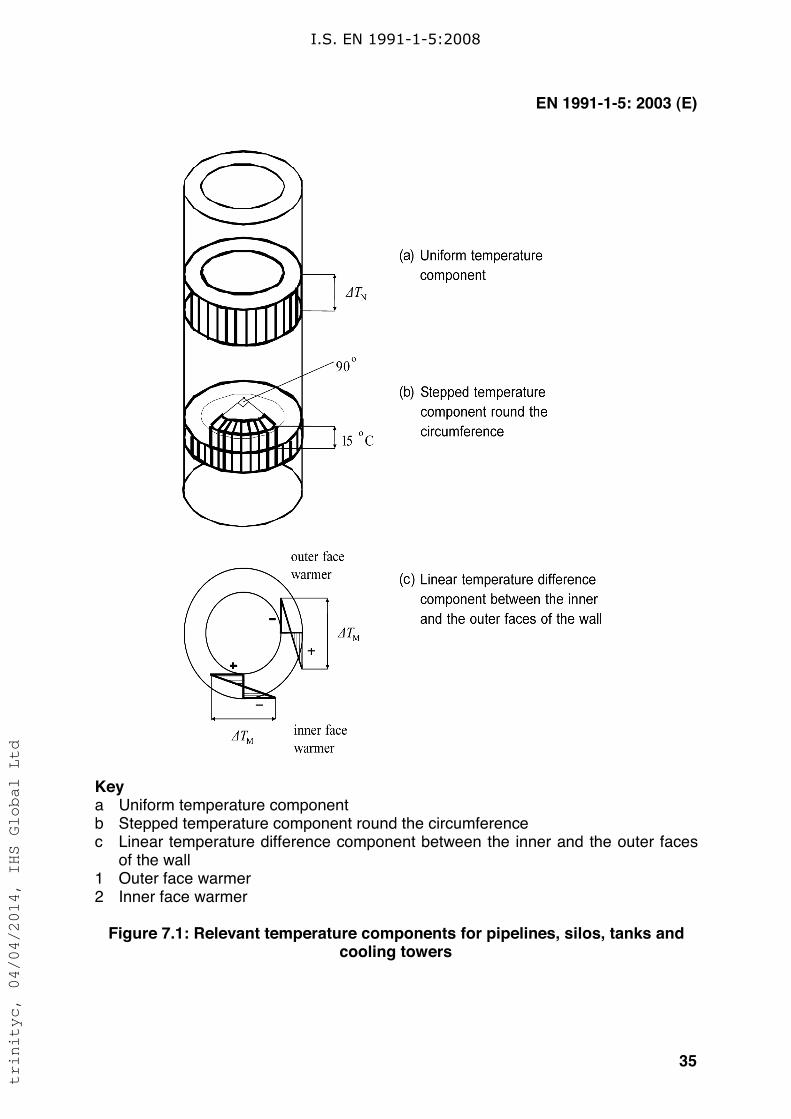
Keya Uniform temperature componentb Stepped temperature component round the circumferencec Linear temperature difference component between the inner and the outer faces
of the wall1 Outer face warmer2 Inner face warmer
Figure 7.1: Relevant temperature components for pipelines, silos, tanks andcooling towers
I.S. EN 1991-1-5:2008
trinityc, 04/04/2014, IHS Global Ltd
EN 1991-1-5: 2003 (E)
36
Annex A(Normative)
Isotherms of national minimum and maximum shade airtemperatures
A.1 General
(1) The values of both annual minimum and annual maximum shade air temperaturerepresent values with an annual probability of being exceeded of 0,02.
NOTE 1: Information (e.g. maps or tables of isotherms) on both annual minimum and annualmaximum shade air temperature to be used in a Country may be found in its National annex.
NOTE 2: These values may need to be adjusted for height above sea level. The adjustmentprocedure is given in the National annex. If no information is available the values of shade airtemperature may be adjusted for height above sea level by subtracting 0,5oC per 100 mheight for minimum shade air temperatures and 1,0oC per 100 m height for maximum shadeair temperatures.
(2) In locations where the minimum values diverge from the values given, such asfrost pockets and sheltered low lying areas where the minimum may be substantiallylower, or in large conurbations and coastal sites, where the minimum may be higherthan that indicated in the relevant figures, these divergences should be taken intoconsideration using local meteorological data.
(3) The initial temperature T0 should be taken as the temperature of a structuralelement at the relevant stage of its restraint (completion). If it is not predictable theaverage temperature during the construction period should be taken.
NOTE: The value of T0 may be specified in the National annex. If no information is availableT0 may be taken as 10oC.
A.2 Maximum and minimum shade air temperature values with an annualprobability of being exceeded p other than 0,02
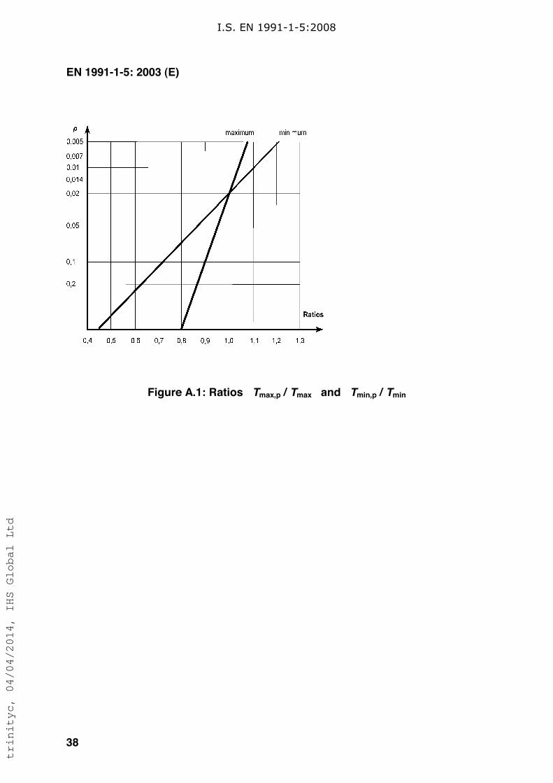
(1) If the value of maximum (or minimum) shade air temperature, Tmax,p (Tmin,p), isbased on an annual probability of being exceeded p other than 0,02, the ratioTmax,p/Tmax (Tmin,p/Tmin) may be determined from Figure A.1.
(2) In general Tmax,p (or Tmin,p) may be derived from the following expressions basedon a type I extreme value distribution:
- for maximum: Tmax,p = Tmax {k1 - k2 ln [ - ln (1-p) ] } (A.1)
- for minimum: Tmin,p = Tmin {k3+ k4 ln [ - ln (1-p) ] } (A.2)
I.S. EN 1991-1-5:2008
trinityc, 04/04/2014, IHS Global Ltd
EN 1991-1-5: 2003 (E)
37
where:
Tmax (Tmin) is the value of maximum (minimum) shade air temperature withan annual probability of being exceeded of 0,02;
k1 = (uc) / { (uc) + 3,902 } (A.3)
k2 = 1 / { (uc) + 3,902 } (A.4)
where:
u,c are the mode and scale parameters of annual maximum shade airtemperature distribution.
k3 = (uc) / { (uc) - 3,902 } (A.5)
k4 = 1 / { (uc) - 3,902 } (A.6)
The parameters u and c are dependent on the mean value m and the standard
deviation ! of type I extreme value distribution:
for maximum u = m - 0,57722 / c
c = 1,2825 / ! (A.7)
for minimum u = m + 0,57722 / cc = 1,2825 / ! (A.8)
The ratios Tmax,p/Tmax and Tmin,p/Tmin respectively may then be taken from Figure A.1.
NOTE1: The National annex may specify the values of the coefficients k1, k2, k3 and k4 basedon the values of parameters u and c. If no other information is available the following valuesare recommended:
k1 = 0,781;
k2 = 0,056;
k3 = 0,393;
k4 = - 0,156.
NOTE 2: Expression (A.2) and Figure A.1 can only be used if Tmin is negative.
I.S. EN 1991-1-5:2008
trinityc, 04/04/2014, IHS Global Ltd
EN 1991-1-5: 2003 (E)
38
Figure A.1: Ratios Tmax,p / Tmax and Tmin,p / Tmin
I.S. EN 1991-1-5:2008
trinityc, 04/04/2014, IHS Global Ltd
EN 1991-1-5: 2003 (E)
39
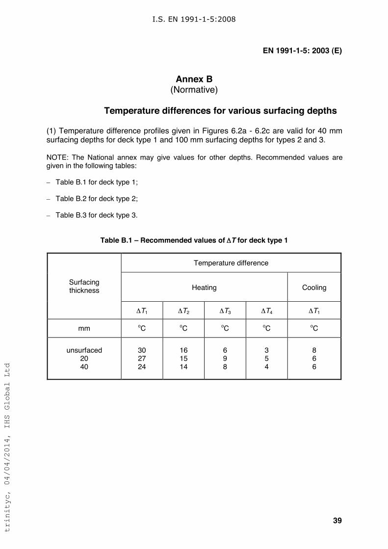
Annex B(Normative)
Temperature differences for various surfacing depths
(1) Temperature difference profiles given in Figures 6.2a - 6.2c are valid for 40 mmsurfacing depths for deck type 1 and 100 mm surfacing depths for types 2 and 3.
NOTE: The National annex may give values for other depths. Recommended values aregiven in the following tables:
– Table B.1 for deck type 1;
– Table B.2 for deck type 2;
– Table B.3 for deck type 3.
Table B.1 – Recommended values of !T for deck type 1
Temperature difference
Heating CoolingSurfacingthickness
!T1 !T2 !T3 !T4 !T1
mm oC oC oC oC oC
unsurfaced2040
302724
161514
698
354
866
I.S. EN 1991-1-5:2008
trinityc, 04/04/2014, IHS Global Ltd
EN 1991-1-5: 2003 (E)
40
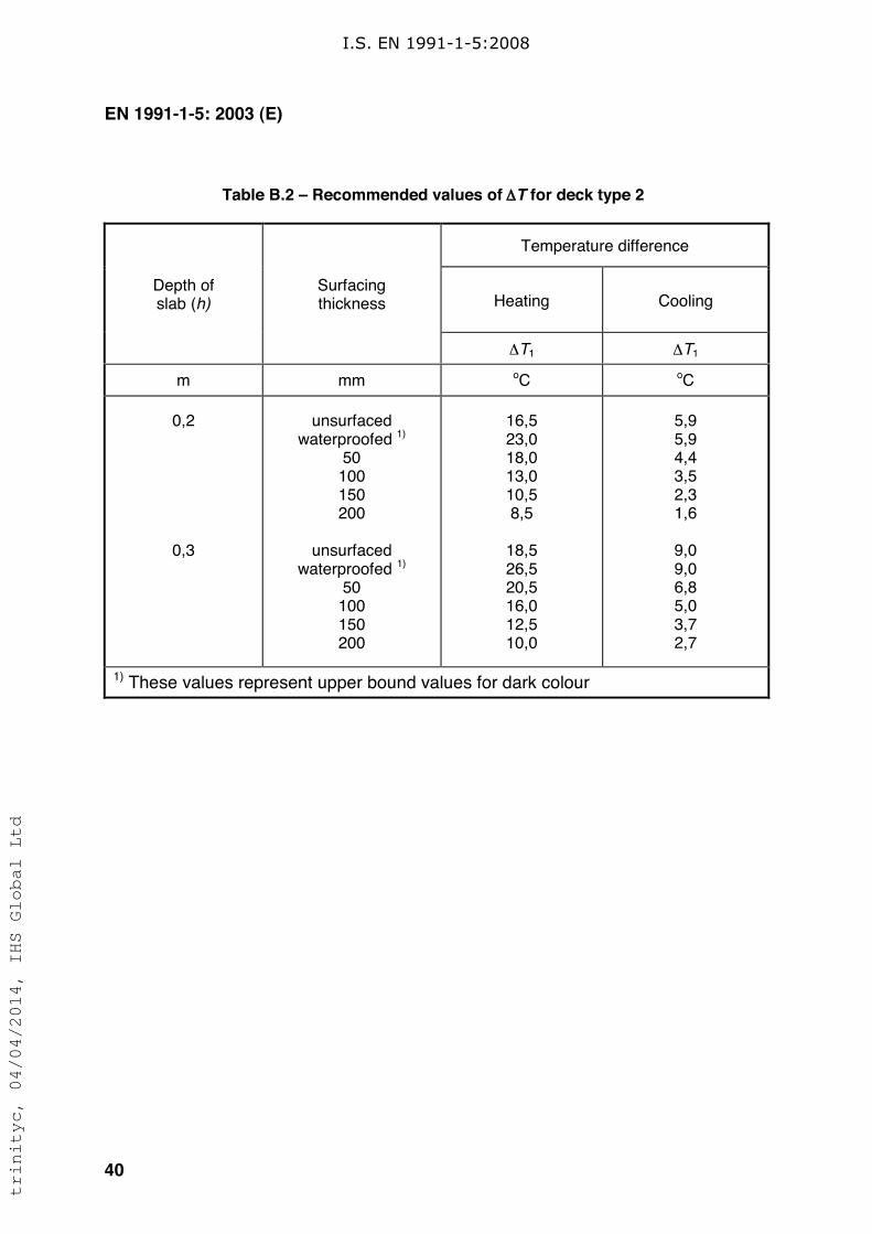
Table B.2 – Recommended values of !T for deck type 2
Temperature difference
Heating CoolingDepth ofslab (h)
Surfacingthickness
!T1 !T1
m mm oC oC
0,2
0,3
unsurfacedwaterproofed 1)
50100150200
unsurfacedwaterproofed 1)
50100150200
16,523,018,013,010,58,5
18,526,520,516,012,510,0
5,95,94,43,52,31,6
9,09,06,85,03,72,7
1) These values represent upper bound values for dark colour
I.S. EN 1991-1-5:2008
trinityc, 04/04/2014, IHS Global Ltd
EN 1991-1-5: 2003 (E)
41
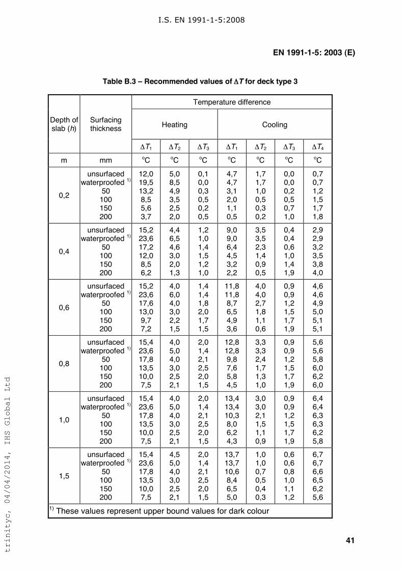
Table B.3 – Recommended values of !T for deck type 3
Temperature difference
Heating CoolingDepth ofslab (h)
Surfacingthickness
!T1 !T2 !T3 !T1 !T2 !T3 !T4
m mm oC oC oC oC oC oC oC
0,2
unsurfacedwaterproofed 1)
50100150200
12,019,513,28,55,63,7
5,08,54,93,52,52,0
0,10,00,30,50,20,5
4,74,73,12,01,10,5
1,71,71,00,50,30,2
0,00,00,20,50,71,0
0,70,71,21,51,71,8
0,4
unsurfacedwaterproofed 1)
50100150200
15,223,617,212,08,56,2
4,46,54,63,02,01,3
1,21,01,41,51,21,0
9,09,06,44,53,22,2
3,53,52,31,40,90,5
0,40,40,61,01,41,9
2,92,93,23,53,84,0
0,6
unsurfacedwaterproofed 1)
50100150200
15,223,617,613,09,77,2
4,06,04,03,02,21,5
1,41,41,82,01,71,5
11,811,88,76,54,93,6
4,04,02,71,81,10,6
0,90,91,21,51,71,9
4,64,64,95,05,15,1
0,8
unsurfacedwaterproofed 1)
50100150200
15,423,617,813,510,07,5
4,05,04,03,02,52,1
2,01,42,12,52,01,5
12,812,89,87,65,84,5
3,33,32,41,71,31,0
0,90,91,21,51,71,9
5,65,65,86,06,26,0
1,0
unsurfacedwaterproofed 1)
50100150200
15,423,617,813,510,07,5
4,05,04,03,02,52,1
2,01,42,12,52,01,5
13,413,410,38,06,24,3
3,03,02,11,51,10,9
0,90,91,21,51,71,9
6,46,46,36,36,25,8
1,5
unsurfacedwaterproofed 1)
50100150200
15,423,617,813,510,07,5
4,55,04,03,02,52,1
2,01,42,12,52,01,5
13,713,710,68,46,55,0
1,01,00,70,50,40,3
0,60,60,81,01,11,2
6,76,76,66,56,25,6
1) These values represent upper bound values for dark colour
I.S. EN 1991-1-5:2008
trinityc, 04/04/2014, IHS Global Ltd
EN 1991-1-5: 2003 (E)
42
Annex C(Informative)
Coefficients of linear expansion
(1) For the determination of action effects due to temperature components, Table C.1gives values for the coefficient of linear expansion for a selection of commonly usedmaterials.
I.S. EN 1991-1-5:2008
trinityc, 04/04/2014, IHS Global Ltd
EN 1991-1-5: 2003 (E)
43
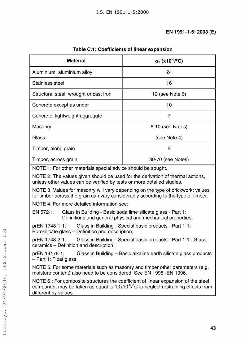
Table C.1: Coefficients of linear expansion
Material !T (x10-6/°C)
Aluminium, aluminium alloy 24
Stainless steel 16
Structural steel, wrought or cast iron 12 (see Note 6)
Concrete except as under 10
Concrete, lightweight aggregate 7
Masonry 6-10 (see Notes)
Glass (see Note 4)
Timber, along grain 5
Timber, across grain 30-70 (see Notes)
NOTE 1: For other materials special advice should be sought.
NOTE 2: The values given should be used for the derivation of thermal actions,unless other values can be verified by tests or more detailed studies.
NOTE 3: Values for masonry will vary depending on the type of brickwork; valuesfor timber across the grain can vary considerably according to the type of timber.
NOTE 4: For more detailed information see:
EN 572-1: Glass in Building - Basic soda lime silicate glass - Part 1:Definitions and general physical and mechanical properties;
prEN 1748-1-1: Glass in Building - Special basic products - Part 1-1:Borosilicate glass – Definition and description;
prEN 1748-2-1: Glass in Building - Special basic products - Part 1-1 : Glassceramics – Definition and description;
prEN 14178-1: Glass in Building – Basic alkaline earth silicate glass products– Part 1: Float glass
NOTE 5: For some materials such as masonry and timber other parameters (e.g.moisture content) also need to be considered. See EN 1995 -EN 1996.
NOTE 6 : For composite structures the coefficient of linear expansion of the steelcomponent may be taken as equal to 10x10-6/oC to neglect restraining effects from
different !T-values.
I.S. EN 1991-1-5:2008
trinityc, 04/04/2014, IHS Global Ltd
EN 1991-1-5: 2003 (E)
44
Annex D(Informative)
Temperature profiles in buildings and other construction works
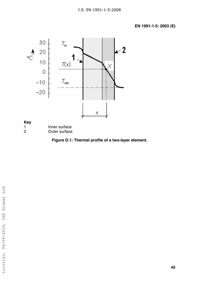
(1) Temperature profiles may be determined using the thermal transmission theory.In the case of a simple sandwich element (e.g. slab, wall, shell) under theassumption that local thermal bridges do not exist a temperature T(x) at a distance xfrom the inner surface of the cross section may be determined assuming steadythermal state as
)()(
)( outin
tot
in TTR
xRTxT !!= (D.1)
where:
Tin is the air temperature of the inner environment
Tout
is the temperature of the outer environment
Rtot
is the total thermal resistance of the element including resistance of
both surfacesR(x) is the thermal resistance at the inner surface and of the element from
the inner surface up to the point x (see Figure D.1).
(2) The resistance values Rtot
, and R(x) [m2K/W] may be determined using the
coefficient of heat transfer and coefficients of thermal conductivity given in EN ISO6946 (1996) and EN ISO 13370 (1998):
outintot Rh
RRi i
i ++= "#
(D.2)
where:
Rin is the thermal resistance at the inner surface [m2K/W]
,R
out is the thermal resistance at the outer surface [m2K/W],
#i is the thermal conductivity and h
i [m] is the thickness of the layer i,
[W/(mK)]
"+=i i
ihRxR
#in)( (D.3)
where layers (or part of a layer) from the inner surface up to point x (see Figure D.1)are considered only.
NOTE: In buildings the thermal resistance Rin = 0,10 to 0,17 [m2K/W] (depending on the
orientation of the heat flow), and Rout
= 0,04 (for all orientations). The thermal conductivity #i
for concrete (of volume weight from 21 to 25 kN/m3) varies from #i = 1,16 to 1,71 [W/(mK)].
I.S. EN 1991-1-5:2008
trinityc, 04/04/2014, IHS Global Ltd
EN 1991-1-5: 2003 (E)
45
Key1 Inner surface
2 Outer surface
Figure D.1: Thermal profile of a two-layer element.
I.S. EN 1991-1-5:2008
trinityc, 04/04/2014, IHS Global Ltd

EN 1991-1-5: 2003 (E)
46
Bibliography
EN 1991-2 Eurocode 1: Actions on structures - Part 2: Traffic loads on bridges
EN 1991-4 Eurocode 1: Basis of design and actions on structures - Part 4: Silos andtanks
I.S. EN 1991-1-5:2008
trinityc, 04/04/2014, IHS Global Ltd

National Annex to Eurocode 1: Actions on structures - Part 1-5: General actions- Thermal actions
Irish National Annex
NA TO I.S. EN 1991-1-5:2003
No copying without NSAI permission except as permitted by copyright law.' NSAI 2003
trinityc, 04/04/2014, IHS Global Ltd
E
91.010.30
5 November, 2008
NA to I.S. EN 1991-1-5:2003
NA to I.S. EN 1991-1-5:2003This document is based on:
This document replaces:
Published:
Price Code:
This document was published
under the authority of the NSAI
and comes into effect on:
NSAI
1 Swift Square,
Northwood, Santry
Dublin 9
T +353 1 807 3800
F +353 1 807 3838
darÆs um ChaighdeÆin NÆisiœnta na h ireann
W NSAI.ie
ICS number:
Incorporating amendments/corrigenda issued since publication:
19 November, 2003
T +353 1 857 6730
F +353 1 857 6729
W standards.ie
Sales:
trinityc, 04/04/2014, IHS Global Ltd
!"#$%#&'('#)!#*++*,*,-./001#
*#
"2234#!"#5627%89:$6;3<#
&86=>#!:$6%2:?#"2234#$%#)@8%A%B3#*.#"A$6%2=#%2#=$8@A$@83=#,#C:8$#*,-.#D3238:?#:A$6%2=#,#E>389:?#:A$6%2=#
&2$8%B@A$6%2#
!"#$%&'(#)*'+%,**-.%"'$%/--*%01-0'1-2%("1)34"%("-%&5,6%&'(#)*'+%731)8)2-$%,29#$)1:%;)<<#((--%'*2%#$%()%/-%3$-2%#*%8)*=3*8(#)*%>#("%6?5?%7&%@AA@B@BCD%EFFG?%
!"'*#(A%F3#
!"#$%&'(#)*'+%,**-.%4#9-$D%
'H% 61#$"% 2-8#$#)*$% I)1% ("-% &'(#)*'++:% J-(-1<#*-2% K'1'<-(-1$% 2-$81#/-2% #*% ("-% I)++)>#*4% $3/8+'3$-$% )I%6?5?%7&%@AA@B@BCDEFFGL%
!% C?GMEH%M!'/+-$%C?@L%C?E%'*2%C?GH% !% N?@?NM@H%
!% N?@?@M@H% !% N?E?@M@HK%
!% N?@?EMEH% !% N?E?EM@H%
!% N?@?G?@MOH% !% N?E?EMEH%
!% N?@?G?EM@H% !% P?E?@M@H%
!% N?@?G?GMGH% !% P?CMGH%
!% N?@?OMGH% !% P?CMOH%
!% N?@?O?@M@H% !% ,?@%M@H%
!% N?@?O?EM@H% !% ,?@%MGH%
!% N?@?O?GM@H% !% ,?E%MEH%%
!% N?@?O?OM@H% !% Q%M@H%M!'/+-$%Q?@L%Q?E%'*2%Q?GH%
!% N?@?CM@H% %
%
/H% 61#$"%2-8#$#)*$%)*%("-%$('(3$%)I%#*I)1<'(#9-%'**-.-$%;%'*2%J%'*2%
8H% R-I-1-*8-$%()%*)*B8)*(1'2#8()1:%8)<0+-<-*('1:%#*I)1<'(#)*?%
trinityc, 04/04/2014, IHS Global Ltd
!"#$%#&'('#)!#*++*,*,-./001#
/#
!"'/#!2$3%42556#78$89:348;#<292:8$89=#
!"'/'*#(>?@52>=8#-'1A/B#78$89:342$3%4#%C#$8:D892$>98#D9%C358=#
!"#$%&'(#)$*#+,--#./#/$0.$!&1'#$234$)",('/$1#$()#/3$
!"#$%&'(#)$*#+,--#./#/$0.$!&1'#$235$)",('/$1#$()#/6$#7+#89$9"&9$9"#$-0.0-(-$)"&/#$&0*$9#-8#*&9(*#$T-0.$&./$ 9"#$ -&70-(-$ )"&/#$ &0*$ 9#-8#*&9(*#$ T-&7$ )",('/$ 1#$ ,19&0.#/$ :*,-$ ;0<(*#$ =>34$ &./$ ;0<(*#$ =>356$*#)8#+90%#'?3$
!"#$%&'(#)$*#+,--#./#/$0.$!&1'#$23@$)",('/$1#$()#/3$
!"'/'/#(>?@52>=8#E'*'*A*B#F93;G8#;8@H#$6D8=##
!"'/'/'*#I848925#
A&'(#)$:,*$9"#$(.0:,*-$9#-8#*&9(*#$+,-8,.#.9$&./$9#-8#*&9(*#$/0::#*#.+#$+,-8,.#.9$:,*$1(*0#/$+,.+*#9#$1,7$&./$ 8,*9&'$ :*&-#$ )9*(+9(*#)6$ &./$ -&),.*?$ &*+"$ 1*0/<#)$ B09"$ ),'0/$ )8&./*#')6$ &*#$ <0%#.$ 0.$ !"'/'/'/# &./$!"'/'/'13$A&'(#)$:,*$,9"#*$9?8#)$,:$1*0/<#)$.,9$+,%#*#/$0.$C3D3$E=$4FF4G4G2$)",('/$1#$&<*##/$:,*$9"#$0./0%0/(&'$8*,H#+9$B09"$9"#$*#'#%&.9$&(9",*09?6$B"#*#$&88*,8*0&9#3$
!"#$:,'',B0.<$-&?$1#$+,.)0/#*#/$9,$1#$8*,9#+9#/$:*,-$+'0-&90+$&./$,8#*&90,.&'$9#-8#*&9(*#$+"&.<#)I$
&J$!"#$B&'')$&./$1&)#$)'&1$,:$1(*0#/$+,.+*#9#$1,7$)9*(+9(*#)$&./$ 9"#$B&'')$,:$1(*0#/$+,.+*#9#$8,*9&'$ :*&-#$)9*(+9(*#)K$
1J$ 0.$)09($1(*0#/$+,.+*#9#$)9*(+9(*#)$B"0+"$"&%#$,%#*$L6M$-#9*#)$,:$+,%#*$ N:0''$8'()$)(*:&+0.<J$&./$B"0+"$&*#$-,*#$9"&.$:0%#$90-#)$&)$',.<$N9*&.)%#*)#'?J$&)$9"#$+'#&*$)8&.$,*6$:,*$-('90)8&.$)9*(+9(*#)6$:0%#$90-#)$&)$',.<$&)$9"#$'&*<#)9$+'#&*$)8&.K$
+J$O*#+&)9$1(*0#/$+,.+*#9#$)#<-#.9)$B"0+"$"&%#$,%#*$L6M$-#9*#)$,:$+,%#*$N:0''$8'()$)(*:&+0.<J$&./$B"0+"$&*#$',+&9#/$-,*#$9"&.$4652$90-#)$9"#$+'#&*$)8&.$:*,-$9"#$#/<#$,:$9"#$)9*(+9(*#3$
P(*0#/$+,.+*#9#$1,7$&./$8,*9&'$ :*&-#$)9*(+9(*#)6$&./$-&),.*?$&*+"$1*0/<#)$B09"$),'0/$)8&./*#')6$)",('/$1#$+'&))0:0#/$&)$!?8#$@$)9*(+9(*#)3$
!"'/'/'/#J43C%9:#$8:D892$>98#@%:D%484$#
;,*$1(*0#/$+,.+*#9#$1,7$&./$8,*9&'$ :*&-#$)9*(+9(*#)6$&./$-&),.*?$&*+"$1*0/<#)$B09"$),'0/$)8&./*#')6$B"#*#$9"#$9,9&'$+,%#*$/#89"$ :*,-$9"#$9,8$,:$ 9"#$)(*:&+0.<$9,$ 9"#$9,8$,:$ 9"#$*,,:$)'&1$,*$#79*&/,)$,:$ 9"#$&*+"$*0.<$ 0)$<*#&9#*$9"&.$5LL$--6$9"#$-0.0-(-$&./$-&70-(-$(.0:,*-$1*0/<#$9#-8#*&9(*#)$,19&0.#/$:*,-$;0<(*#$M346$&./$&/H()9#/$()0.<$!&1'#$=>34$-&?$1#$:(*9"#*$-,/0:0#/$&)$:,'',B)I$
;,*$#%#*?$&//090,.&'$4LL$--$,:$9,9&'$+,%#*$/#89"$0.$#7+#))$,:$5LL$--I$
&J$!"#$-0.0-(-$(.0:,*-$1*0/<#$9#-8#*&9(*#$-&?$1#$0.+*#&)#/$1?$4$QR6$
1J$!"#$-&70-(-$(.0:,*-$1*0/<#$9#-8#*&9(*#$-&?$1#$*#/(+#/$1?$5$QR3$
S,B#%#*6$9"#$/0::#*#.+#$1#9B##.$9"#$-&70-(-$&./$-0.0-(-$(.0:,*-$1*0/<#$9#-8#*&9(*#$)",('/$.,9$1#$9&T#.$&)$'#))$9"&.$42$QR3$
R"&.<#)$0.$(.0:,*-$1*0/<#$9#-8#*&9(*#$-&?$1#$0<.,*#/$B"#.$9"#$9,9&'$/#89"$:*,-$9"#$9,8$,:$9"#$)(*:&+0.<$9,$9"#$9,8$,:$9"#$*,,:$)'&1$,*$#79*&/,)$,:$9"#$&*+"$*0.<$0)$462$-$,*$<*#&9#*3$
trinityc, 04/04/2014, IHS Global Ltd
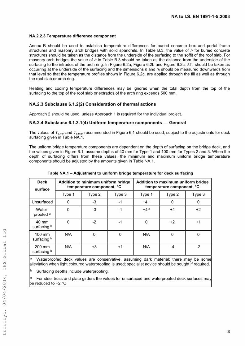
!"#$%#&'('#)!#*++*,*,-./001#
1#
!"'/'/'1#2345367$863#9:;;363<=3#=%45%<3<$#
!""#$% &% '()*+,% -#% *'#,% .)% #'./-+0'(% .#12#3/.*3#% ,044#3#"5#'% 4)3% -*30#,% 5)"53#.#% -)$% /",% 2)3./+% 43/1#%'.3*5.*3#'%/",%1/')"36% /35(%-30,7#'%80.(% ')+0,% '2/",3#+'9% :"%;/-+#%&9<=% .(#% >/+*#%)4%h 4)3% -*30#,% 5)"53#.#%'.3*5.*3#'%'()*+,%-#%./?#"%/'%.(#%,0'./"5#%43)1%.(#%*",#3'0,#%)4%.(#%'*34/50"7%.)%.(#%')440.%)4%.(#%3))4%'+/-9%@)3%1/')"36%/35(%-30,7#'%.(#%>/+*#%)4%h 0"%;/-+#%&9<%'()*+,%-#%./?#"%/'%.(#%,0'./"5#%43)1%.(#%*",#3'0,#%)4%.(#%'*34/50"7%.)%.(#%0".3/,)'%)4%.(#%/35(%30"79%:"%@07*3#%A9B/=%@07*3#%A9B-%/",%@07*3#%A9B5=%!;C%'()*+,%-#%./?#"%/'%)55*330"7%/.%.(#%*",#3'0,#%)4%.(#%'*34/50"7%/",%.(#%,01#"'0)"'%h /",%hC%'()*+,%-#%1#/'*3#,%,)8"8/3,'%43)1%.(/.%+#>#+%')%.(/.%.(#%.#12#3/.*3#%23)40+#'%'()8"%0"%@07*3#%A9B5=%/3#%/22+0#,%.(3)*7(%.(#%40++%/'%8#++%/'%.(3)*7(%.(#%3))4%'+/-%)3%/35(%30"79%
D#/.0"7% /",% 5))+0"7% .#12#3/.*3#% ,044#3#"5#'% 1/6% -#% 07")3#,% 8(#"% .(#% .)./+% ,#2.(% 43)1% .(#% .)2% )4% .(#%'*34/50"7%.)%.(#%.)2%)4%.(#%3))4%'+/-%)3%#$.3/,)'%)4%.(#%/35(%30"7%#$5##,'%EFF%119%
!"'/'1#(8>=?78@3#A'*'/B/C#D%<@:9367$:%<#%;#$E3647?#7=$:%<@#
!223)/5(%B%'()*+,%-#%*'#,=%*"+#''%!223)/5(%C%0'%3#G*03#,%4)3%.(#%0",0>0,*/+%23)H#5.9%
!"'/'F#(8>=?78@3#A'*'1'*BFC#G<:;%64#$345367$863#=%45%<3<$@#H#I3<367?#
;(#%>/+*#'%)4%T#910"%/",%T#91/$%3#5)11#",#,%0"%@07*3#%A9C%'()*+,%-#%*'#,=%'*-H#5.%.)%.(#%/,H*'.1#".'%4)3%,#5?%'*34/50"7%70>#"%0"%;/-+#%I!9C9%
;(#%*"04)31%-30,7#%.#12#3/.*3#%5)12)"#".'%/3#%,#2#",#".%)"%.(#%,#2.(%)4%'*34/50"7%)"%.(#%-30,7#%,#5?=%/",%.(#%>/+*#'%70>#"%0"%@07*3#%A9C=%/''*1#%,#2.('%)4%JF%11%4)3%;62#%C%/",%CFF%11%4)3%;62#'%B%/",%<9%K(#"%.(#%,#2.(% )4% '*34/50"7% ,044#3'% 43)1% .(#'#% >/+*#'=% .(#% 10"01*1% /",% 1/$01*1% *"04)31% -30,7#% .#12#3/.*3#%5)12)"#".'%'()*+,%-#%/,H*'.#,%-6%.(#%/1)*".'%70>#"%0"%;/-+#%I!9C9%
27>?3#!"'*#J#"9K8@$43<$#$%#8<:;%64#>6:9L3#$345367$863#;%6#93=M#@86;7=:<L##
"99:$:%<#$%#4:<:484#8<:;%64#>6:9L3#$345367$863#=%45%<3<$N#OD#
"99:$:%<#$%#47P:484#8<:;%64#>6:9L3#$345367$863#=%45%<3<$N#OD#
Q3=M#
@86;7=3#
;62#%C% ;62#%B% ;62#%<% ;62#%C% ;62#%B% ;62#%<%
L"'*34/5#,% F% M<% MC% NJ%5% F% F%
K/.#3M23))4#,%/%
F% M<% MC% NJ%5% NJ% NB%
JF%11%'*34/50"7%-%
F% MB% MC% F% NB% NC%
CFF%11%'*34/50"7%-%
IO!% F% F% IO!% F% F%
BFF%11%'*34/50"7%-%
IO!% N<% NC% IO!% MJ% MB%
%/% K/.#323))4#,% ,#5?% >/+*#'% /3#% 5)"'#3>/.0>#=% /''*10"7% ,/3?% 1/.#30/+P% .(#3#% 1/6% -#% ')1#%/++#>0/.0)"%8(#"%+07(.%5)+)*3#,%8/.#323))40"7%0'%*'#,P%'2#50/+0'.%/,>05#%'()*+,%-#%')*7(.%04%3#G*03#,9
%-% Q*34/50"7%,#2.('%0"5+*,#%8/.#323))40"79%
%5% @)3%'.##+%.3*''%/",%2+/.#%703,#3'%.(#%>/+*#'%4)3%*"'*34/5#,%/",%8/.#323))4#,%,#5?%'*34/5#'%1/6%-#%3#,*5#,%.)%NB%RS%
%
trinityc, 04/04/2014, IHS Global Ltd
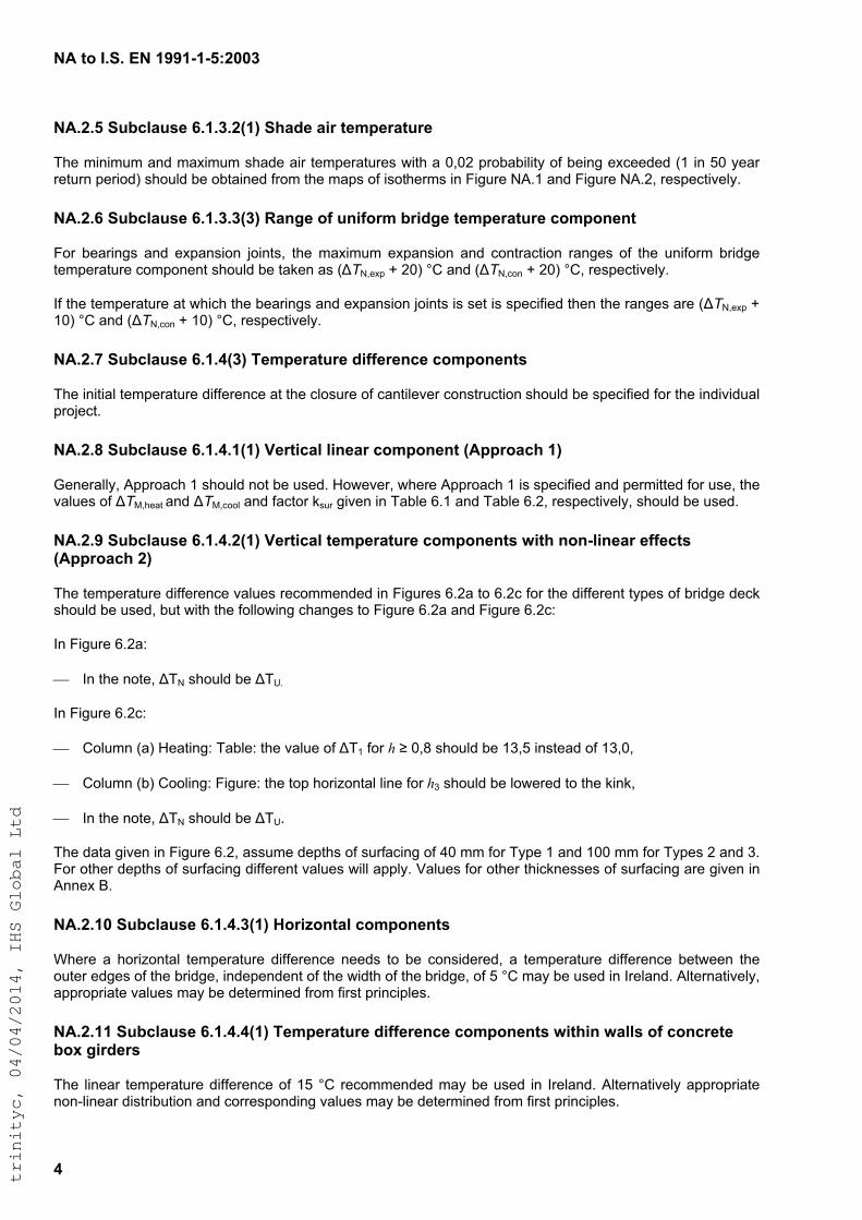
!"#$%#&'('#)!#*++*,*,-./001#
2#
!"'/'-#(34567389#:'*'1'/;*<#(=7>9#7?@#$9AB9@7$3@9##
!"#$%&'&%(%$)'*$%)+&%(%$,")*#$)&-$.#%/#-).(-#,$0&."$)$1213$/-45)5&6&.7$48$5#&'9$#+:##*#*$;<$&'$=1$7#)-$-#.(-'$/#-&4*>$,"4(6*$5#$45.)&'#*$8-4%$."#$%)/,$48$&,4."#-%,$&'$?&9(-#$@AB<$)'*$?&9(-#$@AB32$-#,/#:.&C#67B$
!"'/':#(34567389#:'*'1'1;1<#C7DE9#%F#3D?F%@A#4@?>E9#$9AB9@7$3@9#5%AB%D9D$##
?4-$ 5#)-&'9,$ )'*$ #+/)',&4'$ D4&'.,2$ ."#$%)+&%(%$ #+/)',&4'$ )'*$ :4'.-):.&4'$ -)'9#,$ 48$ ."#$ ('&84-%$ 5-&*9#$.#%/#-).(-#$:4%/4'#'.$,"4(6*$5#$.)E#'$),$;!T@2#+/$F$31>$GH$)'*$;!T@2:4'$F$31>$GH2$-#,/#:.&C#67B$$
I8$."#$.#%/#-).(-#$).$0"&:"$."#$5#)-&'9,$)'*$#+/)',&4'$D4&'.,$&,$,#.$&,$,/#:&8&#*$."#'$."#$-)'9#,$)-#$;!T@2#+/$F$<1>$GH$)'*$;!T@2:4'$F$<1>$GH2$-#,/#:.&C#67B$
!"'/'G#(34567389#:'*'2;1<#H9AB9@7$3@9#>?FF9@9D59#5%AB%D9D$8##
!"#$&'&.&)6$.#%/#-).(-#$*&88#-#':#$).$."#$:64,(-#$48$:)'.&6#C#-$:4',.-(:.&4'$,"4(6*$5#$,/#:&8&#*$84-$."#$&'*&C&*()6$/-4D#:.B$
!"'/'I#(34567389#:'*'2'*;*<#J9@$?576#6?D97@#5%AB%D9D$#;"BB@%75=#*<##
J#'#-)6672$A//-4):"$<$,"4(6*$'4.$5#$(,#*B$K40#C#-2$0"#-#$A//-4):"$<$&,$,/#:&8&#*$)'*$/#-%&..#*$84-$(,#2$."#$C)6(#,$48$!TL2"#).$)'*$!TL2:446$)'*$8):.4-$E,(-$9&C#'$&'$!)56#$MB<$)'*$!)56#$MB32$-#,/#:.&C#672$,"4(6*$5#$(,#*B$
!"'/'+#(34567389#:'*'2'/;*<#J9@$?576#$9AB9@7$3@9#5%AB%D9D$8#K?$=#D%D,6?D97@#9FF95$8#;"BB@%75=#/<##
!"#$.#%/#-).(-#$*&88#-#':#$C)6(#,$-#:4%%#'*#*$&'$?&9(-#,$MB3)$.4$MB3:$84-$."#$*&88#-#'.$.7/#,$48$5-&*9#$*#:E$,"4(6*$5#$(,#*2$5(.$0&."$."#$846640&'9$:")'9#,$.4$?&9(-#$MB3)$)'*$?&9(-#$MB3:N$
I'$?&9(-#$MB3)N$
!$ I'$."#$'4.#2$!!@$,"4(6*$5# !!O.$
I'$?&9(-#$MB3:N$
!$ H46(%'$;)>$K#).&'9N$!)56#N$."#$C)6(#$48$!!<$84-$h$"$12P$,"4(6*$5#$<Q2=$&',.#)*$48$<Q212$
!$ H46(%'$;5>$H446&'9N$?&9(-#N$."#$.4/$"4-&R4'.)6$6&'#$84-$hQ$,"4(6*$5#$640#-#*$.4$."#$E&'E2$
!$ I'$."#$'4.#2$!!@$,"4(6*$5# !!OB$
!"#$*).)$9&C#'$&'$?&9(-#$MB32$),,(%#$*#/.",$48$,(-8):&'9$48$S1$%%$84-$!7/#$<$)'*$<11$%%$84-$!7/#,$3$)'*$QB$?4-$4."#-$*#/.",$48$,(-8):&'9$*&88#-#'.$C)6(#,$0&66$)//67B$T)6(#,$84-$4."#-$."&:E'#,,#,$48$,(-8):&'9$)-#$9&C#'$&'$A''#+$UB$
!"'/'*0#(34567389#:'*'2'1;*<#L%@?M%D$76#5%AB%D9D$8#
V"#-#$ )$ "4-&R4'.)6$ .#%/#-).(-#$ *&88#-#':#$ '##*,$ .4$ 5#$ :4',&*#-#*2$ )$ .#%/#-).(-#$ *&88#-#':#$ 5#.0##'$ ."#$4(.#-$#*9#,$48$."#$5-&*9#2$&'*#/#'*#'.$48$."#$0&*."$48$."#$5-&*9#2$48$=$GH$%)7$5#$(,#*$&'$I-#6)'*B$A6.#-').&C#672$)//-4/-&).#$C)6(#,$%)7$5#$*#.#-%&'#*$8-4%$8&-,.$/-&':&/6#,B$
!"'/'**#(34567389#:'*'2'2;*<#H9AB9@7$3@9#>?FF9@9D59#5%AB%D9D$8#K?$=?D#K7668#%F#5%D5@9$9#4%N#E?@>9@8##
!"#$ 6&'#)-$ .#%/#-).(-#$*&88#-#':#$48$<=$GH$ -#:4%%#'*#*$%)7$5#$(,#*$ &'$ I-#6)'*B$A6.#-').&C#67$)//-4/-&).#$'4'W6&'#)-$*&,.-&5(.&4'$)'*$:4--#,/4'*&'9$C)6(#,$%)7$5#$*#.#-%&'#*$8-4%$8&-,.$/-&':&/6#,B$
trinityc, 04/04/2014, IHS Global Ltd
!"#$%#&'('#)!#*++*,*,-./001#
-#
!"'/'*/#(23456278#9'*'-:*;#(<=25$6>8<$?#%@#2><@%A=#6>B#$8=C8A6$2A8#B<@@8A8>48#4%=C%>8>$7##
!"#$%&'(#)$*+$!,$-$./00$&12$!3$-$./00$4&5$6#$()#2$ 71$ 89#'&12/$6(:$;7:"$ '747:)$*+$!,$ 2#:#9471#2$ +9*4$ :"#$9#'#%&1:$%&'(#$*+$!*$&12$
!$ &<<9*<97&:#$%&'(#)$*+$!#=4&>$&6*%#$?@$AB$+*9$:5<#$.$&12$!#=4&>$&6*%#$.@$AB$+*9$:5<#)$?$&12$C=$
!$ &<<9*<97&:#$%&'(#)$*+$$!#=471$*+$(<$:*$D$AB$6#'*;$:"#$4&>74(4$+*9$:5<#$.$
$ $ $ $ $ $ $ !#=471$*+$(<$:*$E$AB$6#'*;$:"#$4&>74(4$+*9$:5<#$?$
$ $ $ $ $ $ $ !#=471$*+$(<$:*$?$AB$6#'*;$:"#$4&>74(4$+*9$:5<#$C=$
F':#91&:7%#'5/$&<<9*<97&:#$%&'(#)$4&5$6#$2#:#9471#2$+9*4$+79):$<971G7<'#)=$
!"'/'*1#(23456278#9'*'9:*;#D<@@8A8>48#<>#$E8#2><@%A=#$8=C8A6$2A8#4%=C%>8>$7#38$F88>#B<@@8A8>$#7$A24$2A65#858=8>$7##
H"#9#$ 9#'#%&1:/$ :"#$ %&'(#)$ +*9$ :"#$27++#9#1G#)$ 71$ :"#$(17+*94$ :#4<#9&:(9#$ G*4<*1#1:$ 9#G*44#12#2$ 71$ :"#$1*:#$:*$)(6G'&()#$9'*'9:*;$4&5$6#$()#2=$
F':#91&:7%#'5/$&<<9*<97&:#$%&'(#)$4&5$6#$2#:#9471#2$+9*4$+79):$<971G7<'#)=$
!"'/'*G#(23456278#9'/'*:*;H#I%>7<B8A6$<%>#%@#$E8A=65#64$<%>7##
!"#$2#)7I1$<9*G#2(9#$:*$6#$()#2$+*9$:&J71I$:#4<#9&:(9#$27++#9#1G#)$6#:;##1$:"#$*(:#9$+&G#)$*+$6972I#$<7#9)$4&5$&))(4#$&1$#K(7%&'#1:$'71#&9$:#4<#9&:(9#$27++#9#1G#=$
!"'/'*-#(23456278#9'/'/:*;#J8=C8A6$2A8#B<@@8A8>487##
!"#$'71#&9$:#4<#9&:(9#$27++#9#1G#$6#:;##1$:"#$*<<*)7:#$*(:#9$+&G#)$*+$G*1G9#:#$<7#9)$4&5$6#$:&J#1$&)$@$AB$71$89#'&12=$F':#91&:7%#'5/$&<<9*<97&:#$%&'(#)$4&5$6#$2#:#9471#2$+9*4$+79):$<971G7<'#)=$
!"'/'*9#(23456278#9'/'/:/;#J8=C8A6$2A8#B<@@8A8>487#
!"#$'71#&9$:#4<#9&:(9#$27++#9#1G#$6#:;##1$:"#$711#9$&12$*(:#9$+&G#)$*+$;&'')$4&5$6#$:&J#1$&)$.@$AB$71$89#'&12=$F':#91&:7%#'5/$&<<9*<97&:#$%&'(#)$4&5$6#$2#:#9471#2$+9*4$+79):$<971G7<'#)=$
!"#)#$%&'(#)$4&5$%&95$+*9$&$<&9:7G('&9$<9*L#G:$)"*('2$:"#$<7<#)$6#$()#2$:*$G&995$'7K(72)$&:$)<#G7+7G$"7I"$*9$'*;$:#4<#9&:(9#)=$
!"'/'*K#(23456278#K'/'*:*;#(E6B8#6<A#$8=C8A6$2A8##
!"#$47174(4$&12$4&>74(4$)"&2#$&79$:#4<#9&:(9#)$;7:"$&$0/0?$<9*6&67'7:5$*+$6#71I$#>G##2#2$M.$71$@0$5#&9$9#:(91$ <#97*2N$ )"*('2$ 6#$ *6:&71#2$ +9*4$ :"#$ 4&<)$ *+$ 7)*:"#94)$ I7%#1$ 71$ O7I(9#$ ,F=.$ &12$ O7I(9#$ ,F=?/$9#)<#G:7%#'5=$
!"'/'*L#(23456278#K'-'1#M65287#%@#$8=C8A6$2A8#4%=C%>8>$7#:<>B<46$<N8#N65287;#
!"#$'71#&9$:#4<#9&:(9#$27++#9#1G#$G*4<*1#1:$%&'(#$*+$.@$AB$9#G*44#12#2$71$,*:#$.$:*$:"#$)(6G'&()#$)"*('2$6#$()#2=$
!"'/'*+#(23456278#K'-'G#M65287#%@#$8=C8A6$2A8#4%=C%>8>$7#:<>B<46$<N8#N65287;##
!"#$%&'(#$*+$):#<<#2$:#4<#9&:(9#$G*4<*1#1:$*+$.@$AB$9#G*44#12#2$71$:"#$1*:#$:*$:"#$)(6G'&()#$)"*('2$6#$()#2=$
trinityc, 04/04/2014, IHS Global Ltd
!"#$%#&'('#)!#*++*,*,-./001#
2#
!"'/'/0#"3345#"#,#"'*6*7#&8%$94:;8#%<#3=$>%3=?#;>3>;@;#=3A#;=5>;@;#89=A4#=>:#$4;B4:=$@:48#C#D434:=?##
!"#$%&'&%(%$)'*$%)+&%(%$,")*#$)&-$.#%/#-).(-#,$)-#$01.)&'#*$2-0%$."#$%)/,$02$&,0."#-%,$&'$3&4(-#$5678$)'*$ 3&4(-#$ 5679:$ -#,/#;.&<#=>7$ !"#,#$ 2&4(-#,$ -#=).#$ .0$ )$ ?:?9$ /-01)1&=&.>$ #+;##*)';#$ @8$ &'$ A?$ >#)-$ -#.(-'$/#-&0*B7$
!"#$.#%/#-).(-#$<)=(#,$,"0(=*$1#$)*C(,.#*$20-$"#&4".$)10<#$%#)'$,#)$=#<#=$(,&'4$."#$-#;0%%#'*#*$%#."0*$4&<#'$&'$678@8B:$50.#$97$
!"'/'/*#"3345#"#,#"'*617#&8%$94:;8#%<#3=$>%3=?#;>3>;@;#=3A#;=5>;@;#89=A4#=>:#$4;B4:=$@:48#C#D434:=?##
D'$ ."#$ )1,#';#$ 02$ ,/#;&2&;$ .#%/#-).(-#$ &'20-%).&0':$ ."#$ &'&.&)=$ .#%/#-).(-#$ !?$,"0(=*$ 1#$ .)E#'$ ),$ AFG$ 20-$#+/)',&0'$)'*$8A$FG$20-$;0'.-);.&0':$#+;#/.$.").:$20-$1(-&#*$;0';-#.#$10+$,.-(;.(-#,:$."#$<)=(#$02$!?$%)>$1#$.)E#'$),$8?$FG$20-$10."$#+/)',&0'$)'*$;0'.-);.&0'7$H0I#<#-:$."&,$<)=(#$,"0(=*$1#$;0'2&-%#*$&'$."#$&'*&<&*()=$/-0C#;.$1-$
!"#$G0'.-);.0-$,"0(=*$)*<&,#$."#$J#,&4'#-$02$ ."#$.#%/#-).(-#,$).$;-&.&;)=$ .&%#,$*(-&'4$;0',.-(;.&0'$.0$<#-&2>$),,(%/.&0',$%)*#$&'$."#$*#,&4'7$
!"'/'//#"3345#"#E#"/6/7#F=5>;@;#=3A#;>3>;@;#89=A4#=>:#$4;B4:=$@:4#G=?@48#H>$9#=3#=33@=?#B:%I=I>?>$J#%<#I4>3K#45L44A4A#p#%$94:#$9=3#0M0/##
!"#$<)=(#,$02$k8:$k9:$kK:$kL$,"0(=*$1#$.)E#'$),$?:MN8:$?:?AO:$?:KPK$)'*$Q?:8AO$-#,/#;.&<#=>:$),$-#;0%%#'*#*$&'$D7R7$S5$8PP8Q8QAT9??K:$679@9B:$50.#$87$
!"'/'/1#"3345#N#E#N6*7#O4;B4:=$@:4#A><<4:43L48#<%:#G=:>%@8#8@:<=L>3K#A4B$98##
!#%/#-).(-#$ *&22#-#';#$ /-02&=#,$ 20-$ ,(-2);&'4$ *#/.",:$ 0."#-$ .")'$ L?$%%$ 20-$ !>/#$ 8$ )'*$ 8??$%%$ 20-$ *#;E$!>/#,$9$)'*$K:$,"0(=*$1#$),$4&<#'$&'$D7R7$S5$8PP8Q8QAT9??K:$!)1=#$U78:$!)1=#$U79$)'*$!)1=#$U7K:$#+;#/.$I&."$."#$20==0I&'4$;")'4#,$.0$!)1=#$U7KT$
!$ 8,.$;0=(%'T$-#/=);#$0M/#I&."$!#0M/M$
!$ 8,.$;0=(%'T$-#/=);#$*M-#I&."$"#*M-M$
!$ O."$;0=(%'T$8:?%$*#/."$02$,=)1$)'*$9??$%%$,(-2);&'4$."&;E'#,,T$-#/=);#$PM1$I&."$PMQ7$
!"'1#R4L>8>%38#%3#$94#8$=$@8#%<#>3<%:;=$>G4#=334548##
!"'1'*#"3345#S#S%4<<>L>43$8#%<#?>34=:#45B=38>%3##
D'20-%).&<#$6''#+$G$%)>$1#$(,#*$&'$D-#=)'*$I&."$."#$20==0I&'4$#+;#/.&0',$.0$!)1=#$G78T$
!$ R.-(;.(-)=$,.##=:$I-0(4".$0-$;),.$&-0'$V$*#=#.#$-#2#-#';#$.0$50.#$O:$
!$ G0';-#.#$@#+;#/.$=&4".I#&4".$;0';-#.#B$!!$W$89$+$8?QOX!G:$
!$ G78$D4'0-#$'0.#$O7$
!"'1'/#"3345#R#O4;B4:=$@:4#B:%<>?48#>3#I@>?A>3K8#=3A#%$94:#L%38$:@L$>%3#H%:T8##
D'20-%).&<#$6''#+$J$%)>$1#$(,#*$&'$D-#=)'*$),$)'$&'20-%).&<#$)''#+7$
trinityc, 04/04/2014, IHS Global Ltd
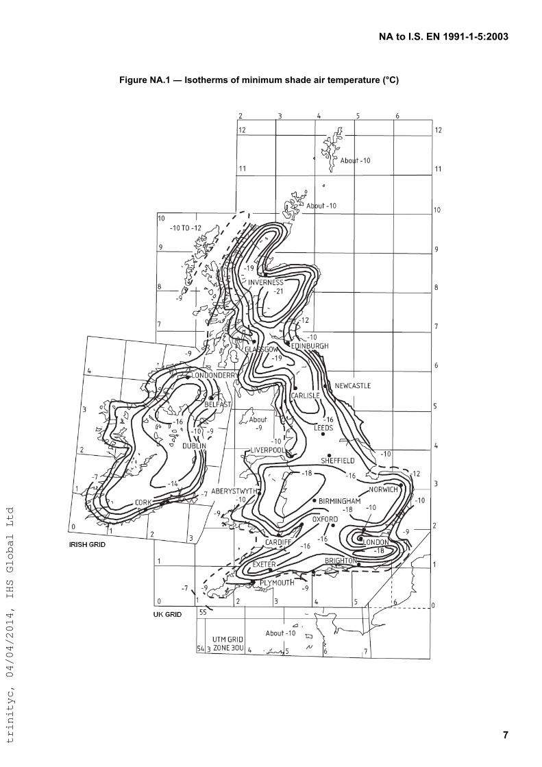
!"#$%#&'('#)!#*++*,*,-./001#
2#
345678#!"'*#!#&9%$:87;9#%<#;4=4;6;#9:>?8#>47#$8;@87>$678#ABCD#
!
!
trinityc, 04/04/2014, IHS Global Ltd
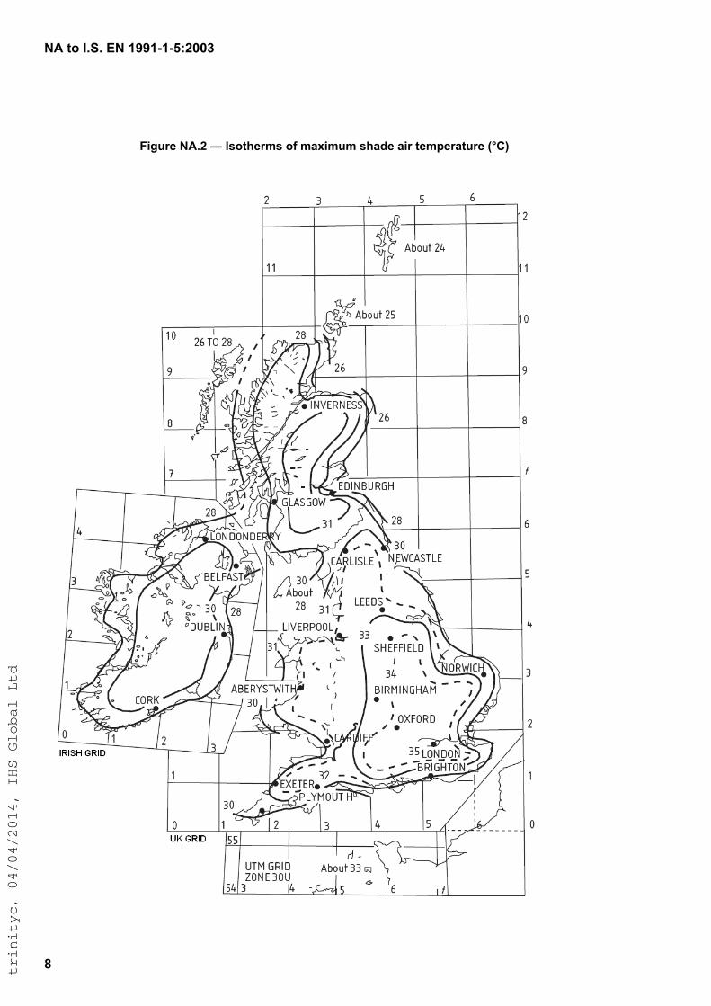
!"#$%#&'('#)!#*++*,*,-./001#
2#
#
345678#!"'/#!#&9%$:87;9#%<#;=>4;6;#9:=?8#=47#$8;@87=$678#ABCD#
!
trinityc, 04/04/2014, IHS Global Ltd

!"#$%#&'('#)!#*++*,*,-./001#
+#
23453%6789:;#
($8<=87=>#9?453@8$3%<>#
!"#"$%&$'(()*'+$#,-./,.-01$230-4567$8$90-,$':$;353-01$<37465$-.137"$
!"#"$%&$'(()*=+$#,-./,.-01$230-4567$8$90-,$=:$#14<456$313>35,7"$
!"#"$%&$'(()*(+$#,-./,.-01$230-4567$8$90-,$(:$%107,?>3-4/$230-4567$@45$A-3A0-0,4?5B"$
!"#"$%&$'(()*C+$#,-./,.-01$230-4567$8$90-,$C:$D?113-$230-4567"$
!"#"$%&$'(()*E+$#,-./,.-01$230-4567$8$90-,$E:$9?,$230-4567"$
!"#"$%&$'(()*F+$#,-./,.-01$230-4567$8$90-,$F: D?/G3-$230-4567$@45$A-3A0-0,4?5B"$
!"#"$%&$'(()*)+$#,-./,.-01$230-4567$8$90-,$):$#AH3-4/01$05<$/I145<-4/01$9JK%$230-4567"$
!"#"$%&$'LLM:=MM=+$%.-?/?<3$8$N0747$?O$7,-./,.-01$<37465"$
!"#"$%&$'LL'$@011$A0-,7B+$%.-?/?<3$'$8$P/,4?57$?5$7,-./,.-37"$
A$:B7#9?453@8$3%<>#
%>3-7?5+$ Q0-I"$ RTemperature differences in bridges: basis of design requirements.S$ T3A0-,>35,$ ?O$ ,H3$%5U4-?5>35,+$JDDV$D3A?-,$VD$)FE"$W-?X,H?-53+$N3-G7H4-3+$Y54,3<$Z456<?>+$'L))"$
$
trinityc, 04/04/2014, IHS Global Ltd