Embed Size (px)
Citation preview
Input –Output Organzation
Shree s’ad vidyamandal institute of technology
DEPARTMENT OF ENGINEERINGINFORMATION TECHNONLGY
• Daxesh Chauhan 130450116004• Patanvadiya Nidhi 130450116020• Thakor Rahual 130450116042• Yadav Deepak 130450116045
Input Output Organization
IO InterfaceModes of transferInterruptDirect Memory AccessIntroduction to IO Processor
IO Interface
• IO interface provides a method for transferring information between internal storage and external I/O devices.
• I/O devices can not directly communicate with the CPU due to various differences between them.
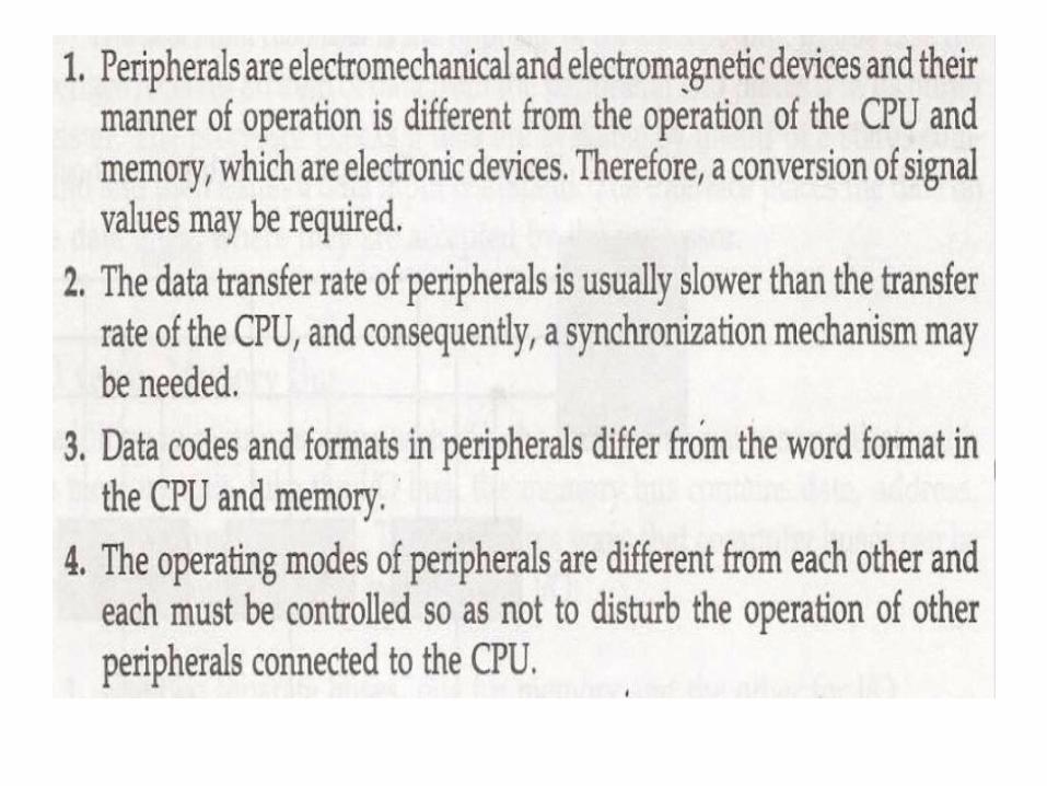
• The major differences are:
I/O Bus and Interface Modules
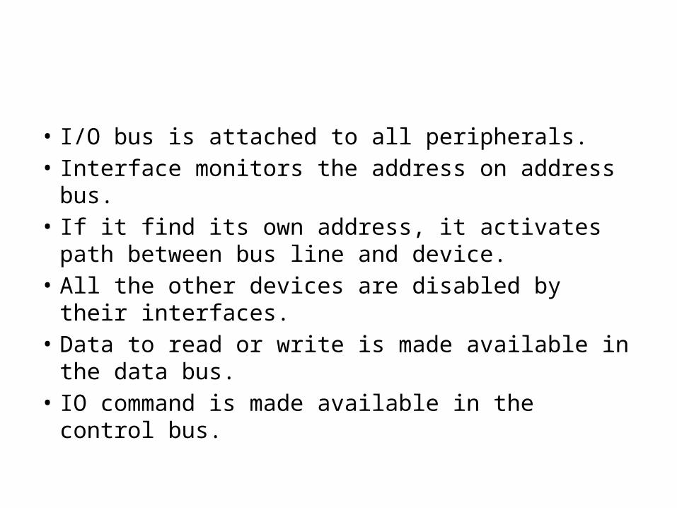
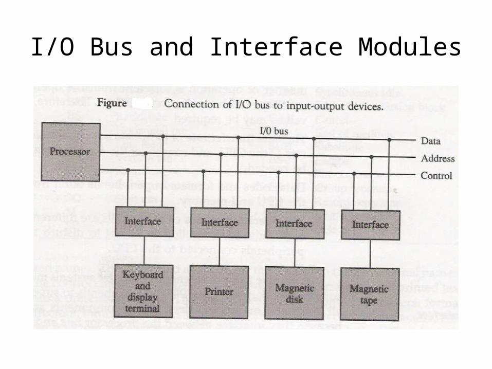
• I/O bus is attached to all peripherals.• Interface monitors the address on address bus.• If it find its own address, it activates path between
bus line and device.• All the other devices are disabled by their
interfaces.• Data to read or write is made available in the data
bus.• IO command is made available in the control bus.
• There are four types of IO command:– Control Command– Status Command– Output Data Command– Input Data Command
IO versus Memory bus
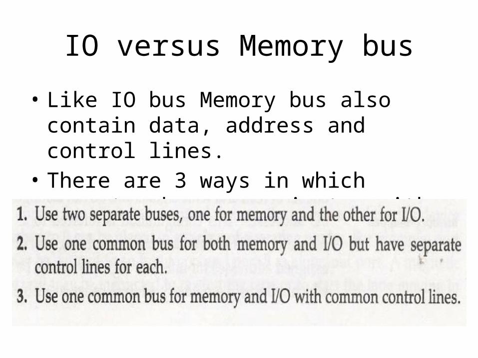
• Like IO bus Memory bus also contain data, address and control lines.
• There are 3 ways in which computer bus communicates with memory and IO.
• In the first method, CPU has independent set of buses for both memory and IO. It is done in computers that has separate IOP and CPU.
• In second method computers use common bus to transfer data between IO or memory and CPU. And separate read and write lines.
• IO read/write is enabled during IO transfer and memory read/write is enabled during memory transfer.
• This configuration isolates all I/O interface address with the memory address and is referred to as Isolated IO method.
• In third method same address space is used for both memory and IO interface. They have only one set of read and write signals.
• Computer treats interface as being part of the memory system.
• It assign address for each interface which cannot be used for memory words.
• This configuration is referred to as memory-mapped IO.
Modes of transfer
• Data transfer between computer and IO device can be handle in the following ways:– Programmed IO– Interrupt-Initiated IO– Direct Memory Access(DMA)
Programmed IO
• Each data transfer is initiated by an instruction in the program.
• CPU stays in the program loop until IO unit indicates it is ready for the data transfer.
• It is time consuming process since it keeps processor busy needlessly.
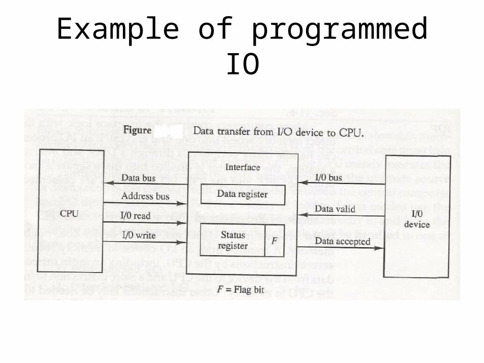
Example of programmed IO
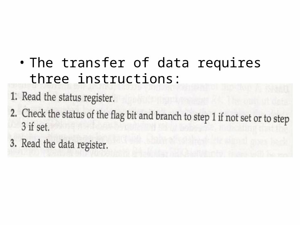
• The transfer of data requires three instructions:
Interrupt Initiated IO
• In this type of IO, computer does not check the flag. It continue to perform its task.
• Whenever any device wants the attention, it sends the interrupt signal to the CPU.
• CPU then deviates from what it was doing, store the return address from PC and branch to the address of the subroutine.
• There are two ways of choosing the branch address:– Vectored Interrupt– Non-vectored Interrupt
• In vectored interrupt the source that interrupt the CPU provides the branch information. This information is called interrupt vectored.
• In non-vectored interrupt, the branch address is assigned to the fixed address in the memory.
Priority Interrupt
• There are number of IO devices attached to the computer.
• They are all capable of generating the interrupt.• When the interrupt is generated from more than
one device, priority interrupt system is used to determine which device is to be serviced first.
• Devices with high speed transfer are given higher priority and slow devices are given lower priority.
• Establishing the priority can be done in two ways:– Using Software– Using Hardware
• A pooling procedure is used to identify highest priority in software means.
Polling Procedure
• There is one common branch address for all interrupts.
• Branch address contain the code that polls the interrupt sources in sequence. The highest priority is tested first.
• The particular service routine of the highest priority device is served.
• The disadvantage is that time required to poll them can exceed the time to serve them in large number of IO devices.
Using Hardware
• Hardware priority system function as an overall manager.
• It accepts interrupt request and determine the priorities.
• To speed up the operation each interrupting devices has its own interrupt vector.
• No polling is required, all decision are established by hardware priority interrupt unit.
• It can be established by serial or parallel connection of interrupt lines.
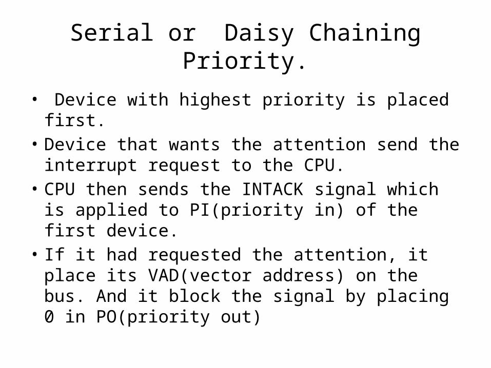
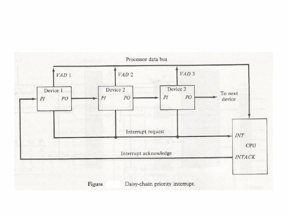
Serial or Daisy Chaining Priority.
• Device with highest priority is placed first.• Device that wants the attention send the
interrupt request to the CPU.• CPU then sends the INTACK signal which is
applied to PI(priority in) of the first device.• If it had requested the attention, it place its
VAD(vector address) on the bus. And it block the signal by placing 0 in PO(priority out)
• If not it pass the signal to next device through PO(priority out) by placing 1.
• This process is continued until appropriate device is found.
• The device whose PI is 1 and PO is 0 is the device that send the interrupt request.
Parallel Priority Interrupt
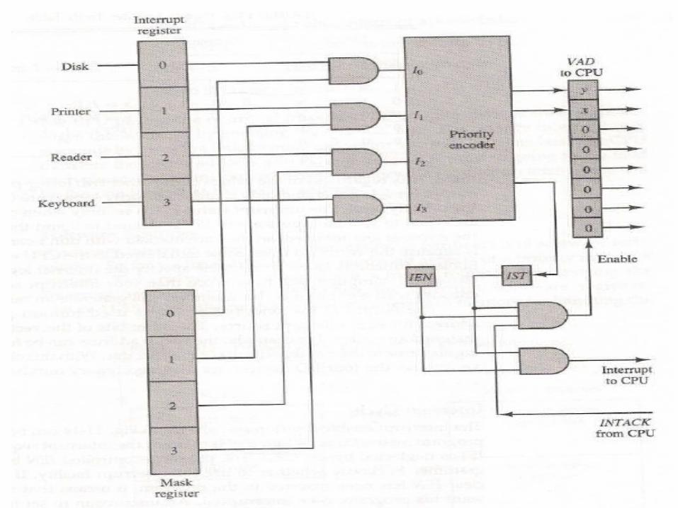
• It consist of interrupt register whose bits are set separately by the interrupting devices.
• Priority is established according to the position of the bits in the register.
• Mask register is used to provide facility for the higher priority devices to interrupt when lower priority device is being serviced or disable all lower priority devices when higher is being serviced.
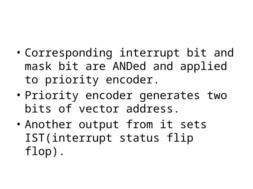
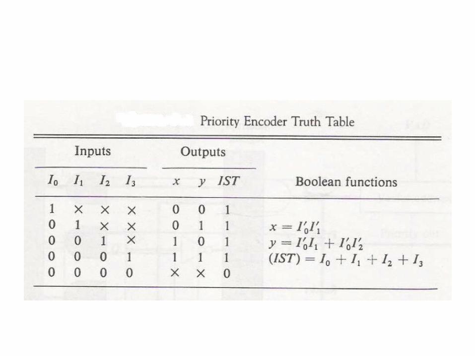
• Corresponding interrupt bit and mask bit are ANDed and applied to priority encoder.
• Priority encoder generates two bits of vector address.
• Another output from it sets IST(interrupt status flip flop).
Direct Memory Access(DMA)
• In DMA there is direct communication between memory and the peripheral devices.
• CPU is idle and has no control over the memory buses.
• DMA controller uses buses and transfer the data directly between I/O devices and memory.

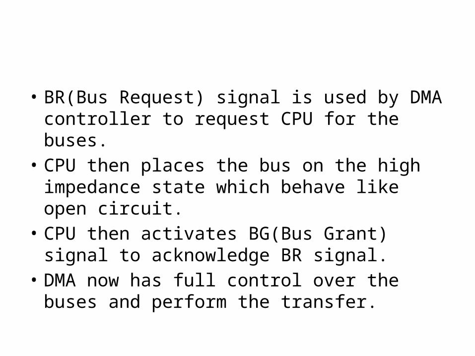
• BR(Bus Request) signal is used by DMA controller to request CPU for the buses.
• CPU then places the bus on the high impedance state which behave like open circuit.
• CPU then activates BG(Bus Grant) signal to acknowledge BR signal.
• DMA now has full control over the buses and perform the transfer.
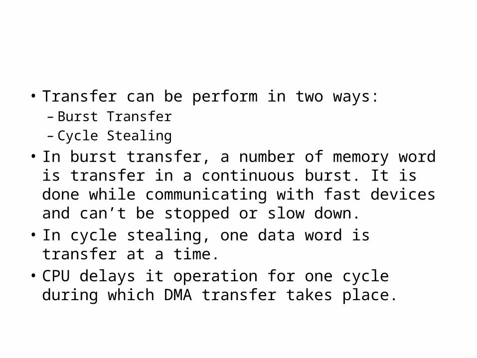
• Transfer can be perform in two ways:– Burst Transfer– Cycle Stealing
• In burst transfer, a number of memory word is transfer in a continuous burst. It is done while communicating with fast devices and can’t be stopped or slow down.
• In cycle stealing, one data word is transfer at a time.• CPU delays it operation for one cycle during which
DMA transfer takes place.
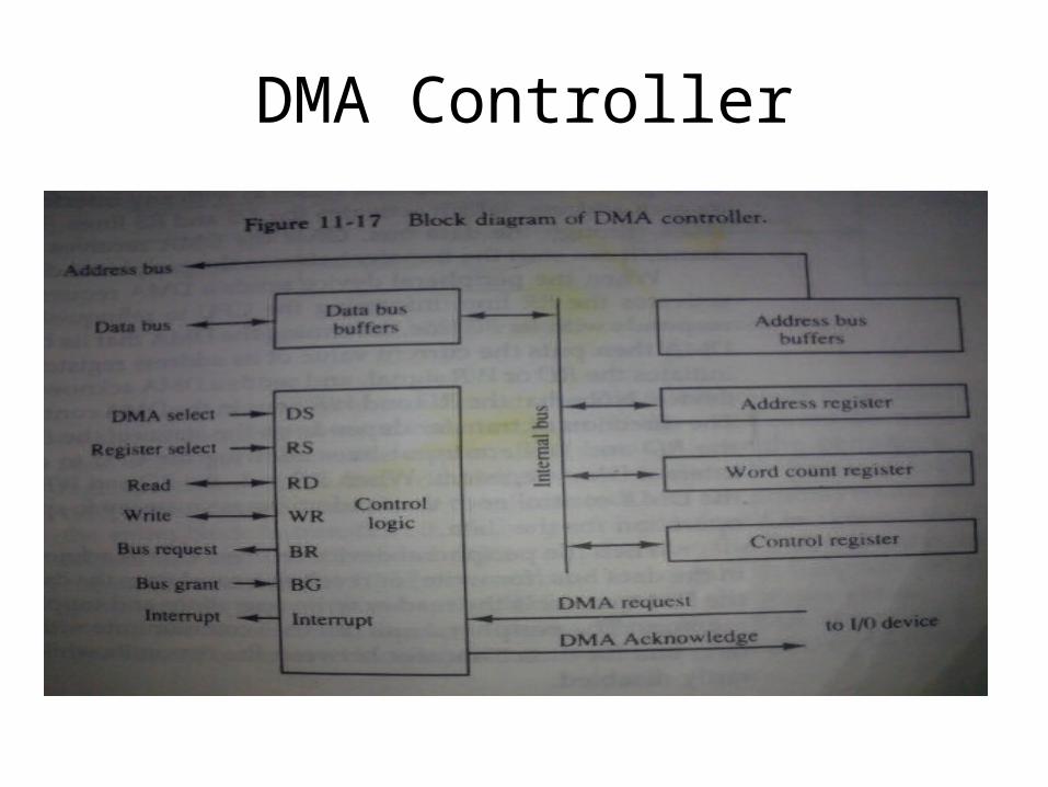
DMA Controller
DMA Controller
• It communicates with CPU through data bus and control lines.
• Registers in DMA are selected by CPU by enabling DS and RS.
• RD and WR signals are for read and write operation.• When BG=0 CPU can communicate with DMA
register for read or write operation.• When BG=1 DMA communicate directly with the
memory.
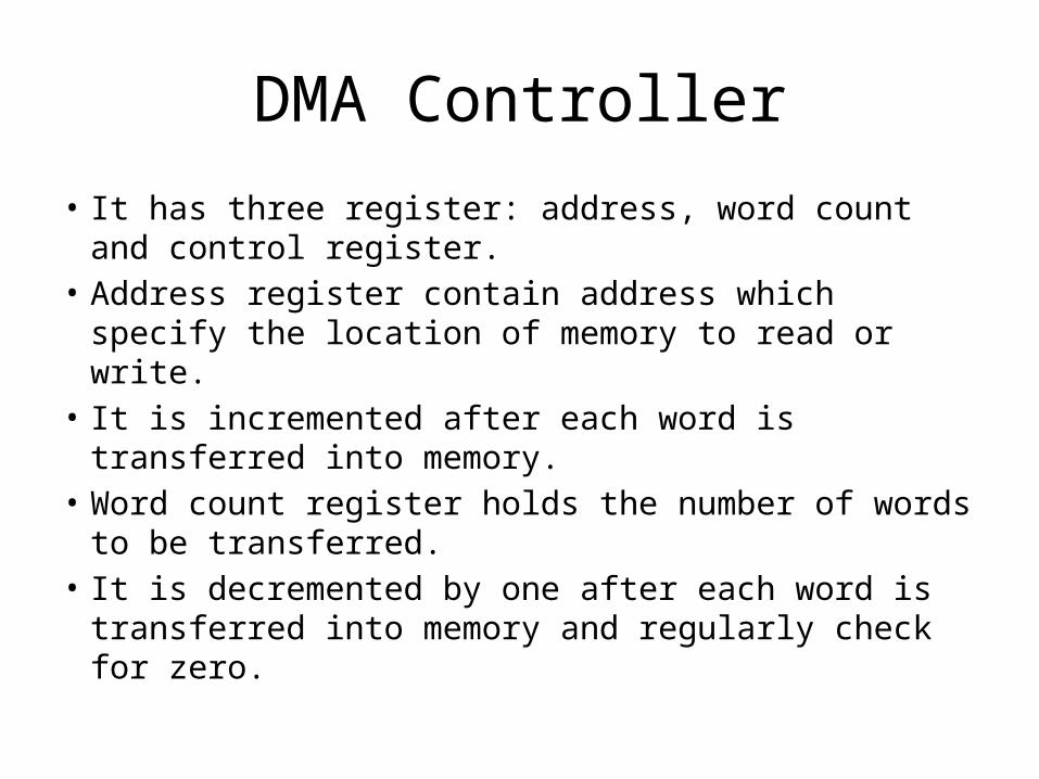
DMA Controller
• It has three register: address, word count and control register.
• Address register contain address which specify the location of memory to read or write.
• It is incremented after each word is transferred into memory.
• Word count register holds the number of words to be transferred.
• It is decremented by one after each word is transferred into memory and regularly check for zero.
• Control Register specify the mode of transfer.• DMA is first initialized by CPU. After that DMA
continue to transfer data.• CPU initialize the DMA by sending the following
information through the data bus:– Starting address of memory block for read or write.– The word count or number of words to read or write.– Control to specify mode such as read or write.– Control to start DMA

• Once DMA is initialized, CPU stop communicating with DMA unless it receive interrupt signal or if it wants to check how many words has been transferred.
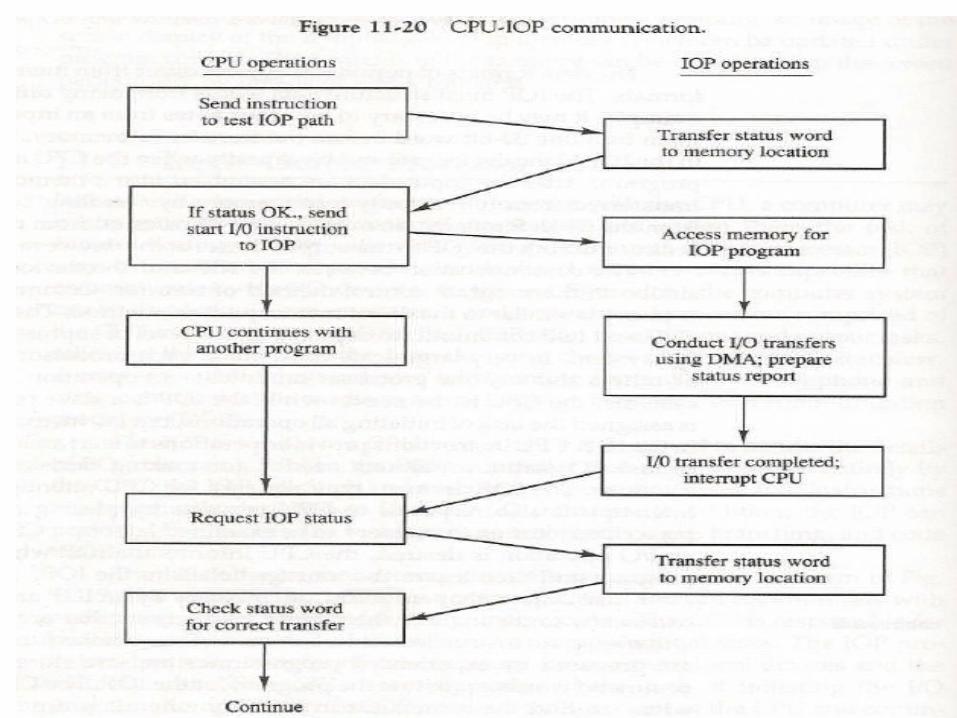
Input-Output Processor(IOP)
• It is a processor with direct memory access capability that communicates with IO devices.
• IOP is similar to CPU except that it is designed to handle the details of IO operation.
• Unlike DMA which is initialized by CPU, IOP can fetch and execute its own instructions.
• IOP instruction are specially designed to handle IO operation.
IOP
IOP
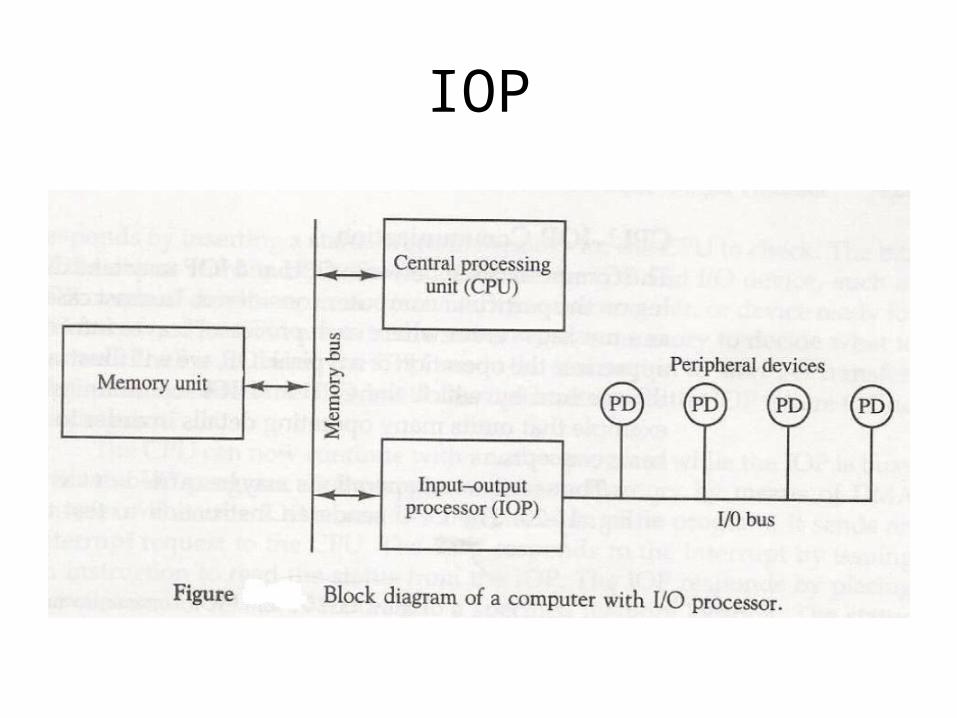
• Memory occupies the central position and can communicate with each processor by DMA.
• CPU is responsible for processing data.• IOP provides the path for transfer of data
between various peripheral devices and memory.• Data formats of peripherals differ from CPU and
memory. IOP maintain such problems.• Data are transfer from IOP to memory by stealing
one memory cycle.
IOP
• Instructions that are read from memory by IOP are called commands to distinguish them from instructions that are read by the CPU.