Embed Size (px)
Citation preview

IOSR Journal of Mechanical and Civil Engineering (IOSR-JMCE)
e-ISSN: 2278-1684,p-ISSN: 2320-334X, Volume 6, Issue 3 (May. - Jun. 2013), PP 05-14 www.iosrjournals.org
www.iosrjournals.org 5 | Page
Influence of the speed in advance and the laser’s power on the
zone affected thermically for steel C45
Sahbi Zantour 1, Meher Gasbar
2, Aleksandr Mikhaylov
3, Hassen Kharroubi
2
1(Department electromechanical, Military Academy Fondek Jdid/ Tunisia) 2(Agricultural Machinery, Superior School of Engineers of Rural Equipment Medjez El Bab/ University
Jendouba, Tunisia) 3(The Machine-Building Technology Department, Donetsk National Technical University, Ukraine)
Abstract: The Laser cutting is a very important manufacturing technology. But this method has some
disadvantages, among which we find the emergence of a Thermically Affected Zone ZAT can dramatically alter
the characteristics of the processed material which affects its behaviour during its use. For this, we have tried in
this article to study the effect of the forward speed and the laser power in this area (thickness, hardening). In
this context, tests were made on steel C45 where we relied on the method of experiment plans to create a
mathematical model Significant coefficients are obtained by carrying out a variance analysis ANOVA on the
level of 5% of significance. We find that the speed in advance and the power of the laser have a great effect on
the ZAT.
Keywords: Cutting, Laser CO2, Heat Affected Zone.
I. Introduction The ZAT is obtained when the temperature of the sample of steel becomes higher or equal to the
specific temperature of the first structure of transformed metal. Steel is transformed into austenite. During the
cooling, austenite undergoes a phase shift of the solid state and is transformed into martensite. The sample
preserves the same chemical composition that austenite, but it changes of crystalline structure quadratic.
Martensite has a great tenacity for simple steels. The part of the steel which undergoes this austenitic
transformation is called the ZAT (Thermically Affected Zone). The ZAT can be characterized by mechanical
micro hardness testing and optically by an optical microscope. These measurements are used to estimate the
width of the ZAT in the morphology of the optimal cut. Neila Jebbari al. [1] have studied the ZAT metal C45
with the assistance of CO2 gas. Fig. 1 shows some examples of grooves with different machining conditions.
ZAT, characterized by whitish areas surrounding the grooves are clearly observable in the photos. The morphology of the ZAT is quite repetitive in general. It is possible to note a reduction in width when going
towards the bottom of the groove. In Fig. 1 (a), irregularities on the edges of the groove can be observed. This
can be attributed to the effect of feedback, which is created when the beam diameter is small impact. The effect
of the laser power can be observed in Fig. 1 (c) (P = 2500 W), wherein the depth of the groove is twice as large
as those of FIG. 1 (a) and (b) (P = 1500 W). When the cutting speed is high, the groove depth and width of the
ZAT become weak due to the short time of laser-matter interaction (Fig. 1 (d)). Fig. 1 (b) is obtained in optimal
machining parameters, where a great regularity in the form of the groove and of the TAZ can be noticed. ZZAT
widths of ZAT were measured at the top of the groove and the average values are displayed on the experimental
curves.
Fig.2 shows the evolution of the experimental value of the width of the ZAT (ZZAT) depending on the
diameter D of laser impact. (ZZAT) increases to a maximum at D = 0.17 mm, and thereafter, it decreases to a limit value. This result confirms the possibility of using the interaction time (increasing with D) and the laser
power density (decreasing with D) to optimize machining.
Fig.1 Morphology of the ZAT

Influence of the speed in advance and the laser’s power on the zone affected thermically for steel C45
www.iosrjournals.org 6 | Page
Fig. 3 (ZZAT) shows that changes linearly with and at the same time, it is linear with V-1 (Fig. 4). In general,
the width of the ZAT as a linear function of x V-1, it can be written as follows:
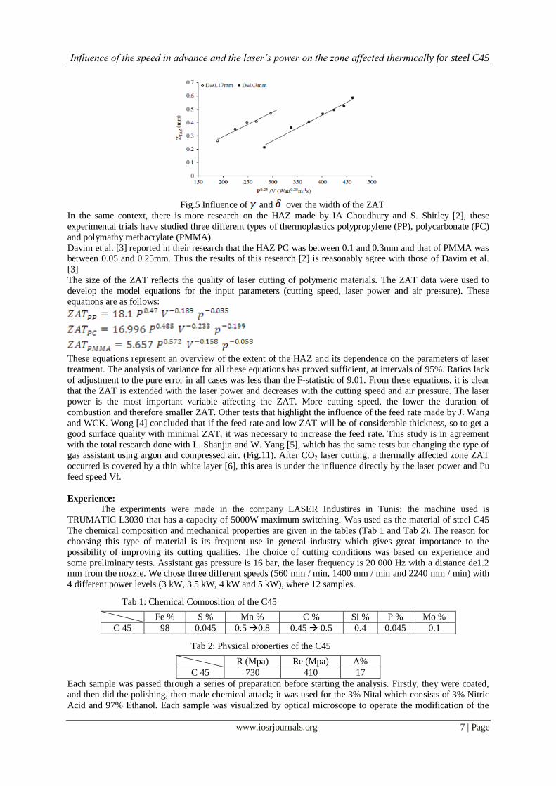
Fig. 5 shows that and depends on the diameter D and the impact of the beam. At the optimum value of the
diameter D of the laser impact (D = 0.17 mm) and from the fitted curves of ZZAT (Fig. 5), it can be deduced that
= 0.0012mm0.75 (kg s)-0,25 and = 0,027 mm.
Fig.2 Influence of the diameter of the laser beam at the impact on the width of the ZAT
Fig.4 Influence of cutting speed on the width of the ZAT
Fig.3 Influence of the power of the laser across the width of the ZAT
Influence of the speed in advance and the laser’s power on the zone affected thermically for steel C45
www.iosrjournals.org 7 | Page
In the same context, there is more research on the HAZ made by IA Choudhury and S. Shirley [2], these
experimental trials have studied three different types of thermoplastics polypropylene (PP), polycarbonate (PC)
and polymathy methacrylate (PMMA).
Davim et al. [3] reported in their research that the HAZ PC was between 0.1 and 0.3mm and that of PMMA was between 0.05 and 0.25mm. Thus the results of this research [2] is reasonably agree with those of Davim et al.
[3]
The size of the ZAT reflects the quality of laser cutting of polymeric materials. The ZAT data were used to
develop the model equations for the input parameters (cutting speed, laser power and air pressure). These
equations are as follows:
These equations represent an overview of the extent of the HAZ and its dependence on the parameters of laser
treatment. The analysis of variance for all these equations has proved sufficient, at intervals of 95%. Ratios lack
of adjustment to the pure error in all cases was less than the F-statistic of 9.01. From these equations, it is clear
that the ZAT is extended with the laser power and decreases with the cutting speed and air pressure. The laser
power is the most important variable affecting the ZAT. More cutting speed, the lower the duration of
combustion and therefore smaller ZAT. Other tests that highlight the influence of the feed rate made by J. Wang
and WCK. Wong [4] concluded that if the feed rate and low ZAT will be of considerable thickness, so to get a
good surface quality with minimal ZAT, it was necessary to increase the feed rate. This study is in agreement
with the total research done with L. Shanjin and W. Yang [5], which has the same tests but changing the type of gas assistant using argon and compressed air. (Fig.11). After CO2 laser cutting, a thermally affected zone ZAT
occurred is covered by a thin white layer [6], this area is under the influence directly by the laser power and Pu
feed speed Vf.
Experience:
The experiments were made in the company LASER Industires in Tunis; the machine used is
TRUMATIC L3030 that has a capacity of 5000W maximum switching. Was used as the material of steel C45
The chemical composition and mechanical properties are given in the tables (Tab 1 and Tab 2). The reason for
choosing this type of material is its frequent use in general industry which gives great importance to the
possibility of improving its cutting qualities. The choice of cutting conditions was based on experience and
some preliminary tests. Assistant gas pressure is 16 bar, the laser frequency is 20 000 Hz with a distance de1.2 mm from the nozzle. We chose three different speeds (560 mm / min, 1400 mm / min and 2240 mm / min) with
4 different power levels (3 kW, 3.5 kW, 4 kW and 5 kW), where 12 samples.
Fe % S % Mn % C % Si % P % Mo %
C 45 98 0.045 0.5 0.8 0.45 0.5 0.4 0.045 0.1
R (Mpa) Re (Mpa) A%
C 45 730 410 17
Each sample was passed through a series of preparation before starting the analysis. Firstly, they were coated,
and then did the polishing, then made chemical attack; it was used for the 3% Nital which consists of 3% Nitric
Acid and 97% Ethanol. Each sample was visualized by optical microscope to operate the modification of the
Fig.5 Influence of and over the width of the ZAT
Tab 2: Physical properties of the C45
Tab 1: Chemical Composition of the C45

Influence of the speed in advance and the laser’s power on the zone affected thermically for steel C45
www.iosrjournals.org 8 | Page
ZAT metal and to measure it. They were then passed through the SEM (scanning electron microscope) in order
to visualize the white layer. Then, it was microhardness tests to know the evolution of the hardness in the ZAT.
After that, we measured the surface roughness with two different devices (3S Surface Scan for 2D profiles and MICROMESURE 2 for 3D profiles).
II. Result and discussion :
2-1 Width of ZAT
The principle of laser cutting is greatly heated surface of the material to be cut until it melts and the
molten part will be removed with the assist gas. But on the other hand, it is absolutely necessary to find a game
that is warm to a temperature that could change its metallurgical and mechanical characteristics; this part is
called the heat affected zone (ZAT).
Found below (Table 3) the results obtained under extreme conditions when measuring the width of the ZAT
after an observation with an optical microscope (Fig. 6).
Num Vf (mm/min) Pu (W) ZAT (µm)
1 560 3000 164,526
2 2240 3000 126,062
3 560 5000 231,638
4 2240 5000 143,017
III. Modeling and Discussion Pour cela on a utilisé la méthode statistique ANOVA avec niveau de confiance de 95% et ont a trouvé
les résultats suivants (tab. 4). For better appreciate the effect of the feed rate Vf and the laser power Pu on the
thickness of the ZAT, and Vf, Pu and the distance from the plane 0 (surface of the part) of the hardness of the
HAZ, modeling was done using the method of experimental design [7]. For this we used the statistical method
ANOVA with a confidence level of 95% and found the following results (Table 4).
Source of variance df SS MS Ftest Ftheoric
Vf 1 8075,340995 8075,341 372,7911 > 7,71
Pu 1 3533,602208 3533,60221 163,12568 > 7,71
Vf,Pu 1 1257,879052 1257,87905 58,068894 > 7,71
Error 4 86,6474 21,6618394
TOTAL 7 12953,4696
According to the ANOVA table (Table 5) we can see that the calculated Ftest feed speed Vf, the laser beam power Pu and their interaction are higher Ftheoric, where these three parameters affect the thickness of the HAZ
and we can not ignore any parameters.
The model calculation gives the following result:
Tab.3: Width of the ZAT as a function of cutting parameters
Fig. 6 Microscopique picture of the ZAT for a cuts out with surface
Vf = 560 mm/min and Pu = 5000 W
Tab.4: Table ANOVA for the measurement thickness of the ZAT of C45

Influence of the speed in advance and the laser’s power on the zone affected thermically for steel C45
www.iosrjournals.org 9 | Page
120
150
4800
3600
30002000
4800
4200
180
210
240
8001200
1600
400
ZAT
Pu
Vf
Diagramme de surface de ZAT et Vf ; Pu
Tab.5: Comparaison between the exprimental resukt and the theorical resultsof the ZAT
Num of test Vf (mm/min) Pu (W) ZAT theorical
(µm) ZAT exprimental (µm) Error
1 560 3000 164,526 164,526 0,00%
2 560 3500 182,419 185,855 1,88%
3 560 4000 199,484 201,738 1,13%
4 560 5000 231,638 231,638 0,00%
5 1400 3000 137,973 139,245 0,92%
6 1400 3500 146,530 141,039 3,75%
7 1400 4000 154,370 150,917 2,24%
8 1400 5000 168,418 168,655 0,14%
9 2240 3000 126,062 126,062 0,00%
10 2240 3500 130,955 135,467 3,45%
11 2240 4000 135,347 141,751 4,73%
12 2240 5000 143,017 143,017 0,00%
According to the model found above, it can be concluded that the ZAT and proportional to the laser beam power
(Pu) (fig.7) and inversely proportional to the feed rate (Vf) (fig.8).
This conclusion can also be seen from the curve effects (Fig. 9), which we can conclude the iso curve response of the thickness of the ZAT (Fig. 10).
Fig.7: Effetc of the power of the laser beam Pu on the thickness of the ZAT
Fig .8: Effect of the speed in advance Vf on the thickness of the ZAT
Fig.9: Curve of the effects of the speed in advance and the power of the laser Pu
on the thickness of the ZAT
(mm/min) (W)
(µm)

Influence of the speed in advance and the laser’s power on the zone affected thermically for steel C45
www.iosrjournals.org 10 | Page
Pu (W)
Vf
(mm
/m
in)
50004500400035003000
2200
2000
1800
1600
1400
1200
1000
800
600
>
–
–
–
–
< 140
140 160
160 180
180 200
200 220
220
ZAT (µm)
Contour Plot of ZAT (µm) vs Vf (mm/min); Pu (W)
I-2 Hard facing
The Hardness is usually defined as resistance of the material resiliently stressed. It is considered one of
the most important properties of metals, mainly because the hardness test is a very simple test to drive though
included some complicated phenomena such as plastic multiaxial behavior. In this study we focused only on the
hardness in the HAZ only. The microhardness measurements were performed with the measuring device:
Testwell.
Measurement type: Vickers hardness at a load of 50g.
Hold time (Duel time) = 10.
The penetration is a straight pyramid with a square base and with an apex angle of 136 ° under a load F = 0.5 N.
Measuring the diagonal "d" of the footprint.
The test is performed at room temperature; the load is applied gradually and steadily until the selected force is
reached. The holding time of the load is 10 seconds.
The impression obtained has a shape of a pyramid with a square base (Fig.11).
A light spot appears on an observation screen of square shape (base of the pyramid).
It takes the average of the two diagonals of the impression: d, and calculates the Vickers hardness (HV50) in the
form:
Found below (Table 6) the results obtained under extreme conditions during the hardness measurement made with the device of micro hardness.
Num Vf (mm/min) Pu (W) D (µm) Hardness (VH)
1 560 3000 10 204
2 2240 3000 10 197
3 560 5000 10 231
4 2240 5000 10 218
5 560 3000 510 187
6 2240 3000 510 175
7 560 5000 510 203
8 2240 5000 510 189
Fig.10: Curve iso answer thickness of the ZAT
Fig.11 : Hardness Test.
Tab.6: Measurements of hardness according to the parameters of cut and surface’s depth

Influence of the speed in advance and the laser’s power on the zone affected thermically for steel C45
www.iosrjournals.org 11 | Page
Modeling and discussion:
For better appreciate the effect of the feed rate Vf and the laser power Pu on the thickness of the ZAT,
and Vf, Pu and the distance from the plane 0 (surface part) of the hardness of the ZAT, modeling was done
using the method of experimental design [7]. For this we used the statistical method ANOVA with a confidence
level of 95% and found the following results (Table 4).
Tab.7: ANOVA Table (Hardness of C45 steel)
Source of
variance
df SS MS Ftest Ftheorical
Vf 1 1088,297858 1088,29786 2,0749306 5,32
Pu 1 3092,596658 3092,59666 5,8962934 5,32
D 1 4550,58 4550,58 8,6760602 5,32
Vf, Pu 1 24,808968 24,808968 0,0473004 5,32
Vf, D 1 10,829858 10,829858 0,020648 5,32
Pu, D 1 150,580658 150,580658 0,2870946 5,32
Vf, Pu, D 1 12,280968 12,280968 0,0234147 5,32
Error 8 4195,9875 524,498436
TOTAL 7 13125,96245
The ANOVA table and the Fisher test shows that a significant level of 5%. Fcalculated for Pu and D are higher
Ftheorical so they are meaningful answer. But Fcalculated of Vf is less than Ftheorical but it is not negligible, so Vf is
quite significant influence on the response. On all interactions, Fcalculated shows that they can be ignored and do
not affect the response. The model calculation gives the following result:
Tab.8: Comparaison between exprimental results and theorical results of hardness
Num of test Vf (mm/min) Pu (W) D (µm) Theorical
hardness(VH) Exprimental
hardness (VH) Error
1 560 3000 10 209,888 204 3%
2 560 3500 10 215,4493 214,5 0%
3 560 4000 10 220,3856 223,5 1%
4 560 5000 10 228,8884 231 1%
5 1400 3000 10 200,6489 205,2 2%
6 1400 3500 10 205,9653 210 2%
7 1400 4000 10 210,6843 220,65 5%
8 1400 5000 10 218,8128 225,45 3%
9 2240 3000 10 196,0687 196,5 0%
10 2240 3500 10 201,2638 204 1%
11 2240 4000 10 205,8751 211,11 3%
12 2240 5000 10 213,818 217,5 2%
Fig.12: Print of the Micro hardness of the various zone Constituting the
termically affected zone.

Influence of the speed in advance and the laser’s power on the zone affected thermically for steel C45
www.iosrjournals.org 12 | Page
1 560 3000 210 191,8503 197,25 3%
2 560 3500 210 196,9336 202,5 3%
3 560 4000 210 201,4457 207 3%
4 560 5000 210 209,2178 207,45 1%
5 1400 3000 210 183,4052 191,05 4%
6 1400 3500 210 188,2647 196,5 4%
7 1400 4000 210 192,5782 202,5 5%
8 1400 5000 210 200,0081 209,7 5%
9 2240 3000 210 179,2186 178,95 0%
10 2240 3500 210 183,9672 187,5 2%
11 2240 4000 210 188,1822 191,22 2%
12 2240 5000 210 195,4426 192 2%
1 560 3000 110 195,547 200,7 3%
2 560 3500 110 200,7282 211,5 5%
3 560 4000 110 205,3273 217,5 6%
4 560 5000 110 213,2491 226,5 6%
5 1400 3000 110 186,9391 192,22 2%
6 1400 3500 110 191,8923 202,5 6%
7 1400 4000 110 196,2889 208,95 6%
8 1400 5000 110 203,862 207,95 2%
9 2240 3000 110 182,6718 187,5 3%
10 2240 3500 110 187,512 195 4%
11 2240 4000 110 191,8082 191,65 0%
12 2240 5000 110 199,2084 202,95 2%
According to the model found above, it can be concluded that the HAZ and proportional to the laser beam
power (Pu) and inversely proportional to the feed rate (Vf) and the depth from the surface (D) (Fig.13). This
conclusion can be seen from curve effects (Fig. 14), where one can conclude Iso curve responses hardness (fig.15, fig.16, fig.17).
MB
Fig.13: Evolution of the hardness of the steel C45 according to the depth D

Influence of the speed in advance and the laser’s power on the zone affected thermically for steel C45
www.iosrjournals.org 13 | Page
2240560
210
205
200
195
190
50003000
51010
210
205
200
195
190
Vf
Me
an
Pu
P
Main Effects Plot for DuretéData Means
Pu (W)
Vf
(mm
/m
in)
50004500400035003000
2200
2000
1800
1600
1400
1200
1000
800
600
>
–
–
–
–
–
–
< 200
200 205
205 210
210 215
215 220
220 225
225 230
230
(VH)
Dureté
Contour Plot of Dureté (VH) vs Vf (mm/min); Pu (W)
D (µm)
Vf
(mm
/m
in)
500400300200100
2200
2000
1800
1600
1400
1200
1000
800
600
>
–
–
–
–
–
< 175
175 180
180 185
185 190
190 195
195 200
200
(VH)
Dureté
Contour Plot of Dureté (VH) vs Vf (mm/min); D (µm)
D (µm)
Pu
(W
)
500400300200100
5000
4500
4000
3500
3000
>
–
–
–
–
< 190
190 200
200 210
210 220
220 230
230
(VH)
Dureté
Contour Plot of Dureté (VH) vs Pu (W); D (µm)
Fig.14: Effects of the speed in advance Vf and the power of the laser Pu and the
depth D on hardness of C45
Fig.15: Iso response curve hardness according to the speed in advance Vf and the
power of the laser beam Pu (D = 10µm)
Fig.17: Iso response curve as a function of the hardness feedrate Vf and the depth
from the surface D (Pu = 3000 W)
Fig.16: Iso response curve hardness versus the depth from the surface D and the laser
beam power Pu (Vf = 560 mm / min)

Influence of the speed in advance and the laser’s power on the zone affected thermically for steel C45
www.iosrjournals.org 14 | Page
IV. Conclusion: After CO2 laser cutting of steel C45, there is a ZAT heat that appears undergoing metallurgical and
physical changes important this area is under the influence directly:
The speed in advance :
- Is proportional to the thickness of the ZAT.
- Is inversely proportional to the hardness of the ZAT.
The Laser’s power
- - It is proportional to the thickness of the ZAT.
- - It is proportional to the hardness of the ZAT.
Bibliographic reference: [1] Neila Jebbari, Mohamed Mondher Jebari, Faycal Saadallah, Annie Tarrats-Saugnac, Raouf Bennaceur, Jean Paul Longuemard
(2007). "Thermal affected zone obtained in machining steel XC42 by high-power continuous CO2 laser". Optics and Laser
Technology 40 (2008) 864-873.
[2] I.A. Choudhury, S. Shirley (2009). "Laser cutting of polymeric materials: An experimental investigation". Optics and Laser
Technology 42 (2010) 503-508.
[3] Davim JP, Barricas N, Conceição M, Oliveira C. "Some experimental studies on CO2 laser cutting quality of polymeric materials".
Journal of Materials Processing Technology 2008; 198 (1-3):99-104.
[4] J. Wang, W.C.K. Wong. “CO2 laser cutting of metallic coated sheet steels”. Journal of Materials Processing Technology 95 (1999)
164-168.
[5] Lv. Shanjin, Wang Yang. “An investigation of pulsed laser cutting of titanium alloy sheet”. Optics and Laser in Engineering 44
(2006) 1067-1077.
[6] B. Tirumala Rao, Rakesh Kaul, Pragya Tiwari, A.K. Nath. “Inert gas cutting of titanium sheet with pilsed mode CO2 laser”. Optics
and Laser in Engineering 43 (2005) 1330-1348.
[7] Sivarao, T.J.S. Anand, Ammar, Shukor. “RSM Based Modeling for Surface Roughness Prediction in Laser Machining”.
Inetrnational Journal of Engineering & Technology IJET-IJENS Vol: 10 No 04.