Embed Size (px)
Citation preview

Process of Air conditioning

Moving Heat from the Inside to the Outside

Heat Transfer at the Inside Coil
Evaporator Coil—Collecting Hot Air Inside the House
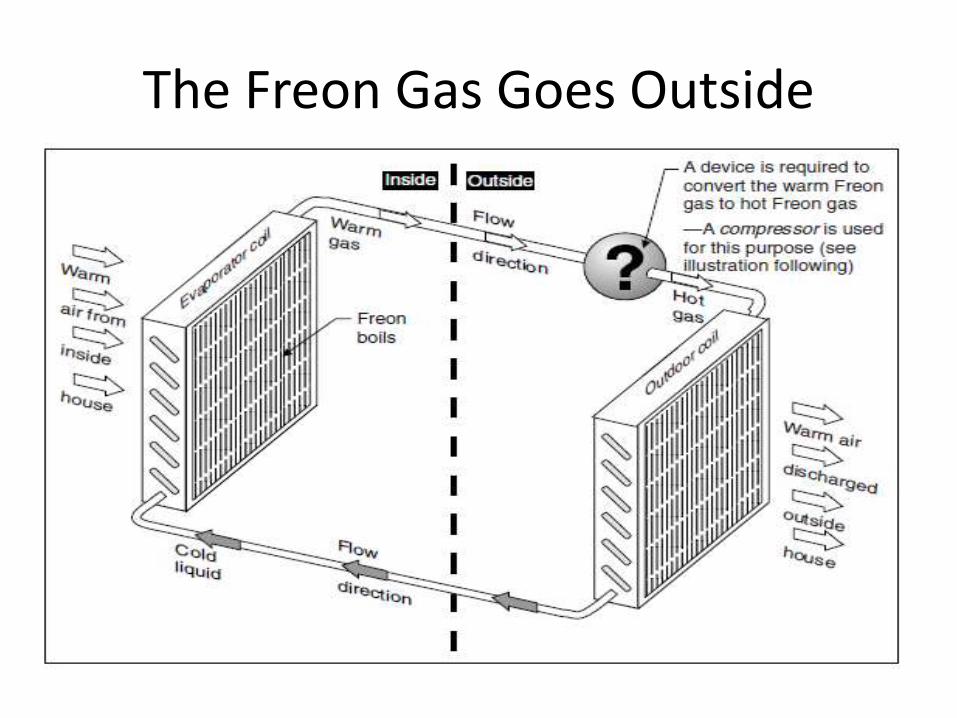
The Freon Gas Goes Outside

Compressors—Heating up Freon Gas

Condenser Coil—Exhausting Hot Air to the Outside

Hot Liquid Back to House

Expansion Devices—Cooling Hot Liquid Freon

Air Conditioning—Schematic of System

Latent Heat of Vaporization

Discharging Condensate

High-Pressure and Low-Pressure Sides

Inspecting the Condenser Unit
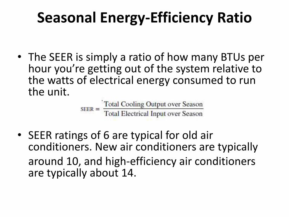
Seasonal Energy-Efficiency Ratio
• The SEER is simply a ratio of how many BTUs per hour you’re getting out of the system relative to the watts of electrical energy consumed to run the unit.
• SEER ratings of 6 are typical for old air conditioners. New air conditioners are typicallyaround 10, and high-efficiency air conditioners are typically about 14.

Water-Cooled Air Conditioning—Schematic of System

One Ton of Cooling

How Much Area Can One Ton Cool?
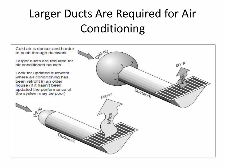
Larger Ducts Are Required for Air Conditioning

Bigger is not Better

Guessing the Size

Measure Temperature Drop across Inside Coil

1
HVAC
2

3
DEFINITIONS

4
Air Conditioning Process of treating air so as to control
simultaneously its temperature, humidity,
cleanliness, and distribution to meet the
environmental requirements of the conditioned
space.
Environmental requirements of the conditioned
space may be determined by human occupancy
as related to comfort and health, a process, or a
product.

5
Air Conditioning Processes
Heating: Transfer of energy to the air in a space.
Cooling: Transfer of energy from the air in a space.
Humidifying: Transfer of water vapor to the air in a
space.
Dehumidifying: Removal of water vapor from the air in
the space.
Cleaning: Removal of particulate and biological
contaminants from the air in a space.
Air Motion (Circulation): movement of air through the
spaces in a building to achieve the proper ventilation and
facilitate the energy transfer, humidification (or
dehumidification), and cleaning processes described above.

6
Energy
The capacity for producing an effect
Either stored or transient, and can be
transformed from one to another
Forms include: thermal (heat),
mechanical (work), electrical, chemical

7
Heat
Energy in transit from one mass to
another as a result of a temperature
difference between two masses.
A basic law of thermodynamics states that
heat always flows from a higher
temperature to a lower temperature

PRINCIPLE ONE
Heat ALWAYS flows
from hot to cold when
objects are in contact
or connected by a
good heat conductor.
The rate of heat
transfer will increase
as the difference in
temp between the two
objects increases

PRINCIPLE TWO
Cold objects have less
heat than hot objects of
the same mass.
To make a object
colder, remove heat
To make it hotter, add
heat.
The mass of the object
remains the same
regardless of the heat
content.

EVAPORATION
The process of moisture becoming a
vapor(molecules escaping from the surface
of the liquid)
As moisture vaporizes from a warm surface,
it removes heat and lowers the
temperature of the surface.
The warmer the substance the quicker it
will evaporate.
PRINCIPLE THREE
Everything is composed of matter
All matter exists in one of three states: solid,
liquid or vapor.
LATENT HEAT OF VAPORIZATION: When
matter changes from liquid to vapor or vice
versa, it absorbs or releases a relatively large
amount of heat without a change in
temperature.

12
Sensible Heat
Heat which changes the temperature
of a substance without changing its
state.

13
Latent Heat
Heat which changes the state of a substance
without changing its temperature.
Two familiar examples: latent heat of fusion
(changing ice to water) and latent heat of
vaporization (changing water to vapor)
MBH stands for One Thousand BTU per hour. BTU stands for
British Thermal Unit. MBh units should help with the cost
estimate of running your air conditioning (AC). It's a measure of
the heating/cooling capacity of AC equipment.
MBH - One MBH is equivalent to 1,000 BTU's per hour. The 'M'
is derived from the Roman Numeral M that equals 1000.Note
BTUs and therefore MBH are Imperial Units.)
BTU - A standard unit of measurement used to denote both the
amount of heat energy in fuels and the ability of appliances and air
conditioning systems to produce heating or cooling. It is the
amount of heat required to increase the temperature of a pint of
water by one degree Fahrenheit.
BTUs are measurements of energy consumption, and can be
converted directly to kilowatt-hours (3412 BTUs = 1 kWh) or
joules (1 BTU = 1,055.06 joules).
14

BRITISH THERMAL UNIT BTU is a heat quantity
measure.
BTU is the quantity of heat
needed to raise the
temperature of 1 lb. of water
one degree Fahrenheit.
Vaporization: Will absorb
more than five times amount
of heat.
1 ton = 12,000 BTU/hr.
12,000 BTU/hr = 3,516Watts
or 3.516 kW (kilo-Watts).

16
Heat Energy Flow Rate
Rate of heat loss/heat gain associated
with buildings.
Also associated with applied heating and
air conditioning equipment.
Normally stated in the terms BTU/hr.

PRINCIPLE FOUR
CONDENSATION
When a vapor is cooled
below its dew point, it
becomes a liquid.
(boiling point in reverse)
When vapor condenses,
releases five times as
much heat

PRINCIPLE FIVE
Changing the pressure on
a liquid or a vapor changes
the boiling point.
Each lb. of pressure above
atmospheric pressure,
raises the boiling point
about three degrees
Fahrenheit.

PRINCIPLE SIX
When a vapor is
compressed, its
temperature and
pressure will increase
even though heat has
not been added.

20
HEAT TRANSFER/HEAT GENERATION

21
Heat Transfer
Movement of heat through surfaces and openings of
a building
Usually assumed to be steady state (various
temperatures throughout a system remain constant
with respect to time during heat transmission)
Based upon predetermined temperature differences
22
Heat Loss/ Heat Gain
Heat Loss – heat transferred from the interior of a
building to its exterior
Heat Gain – heat transferred from the exterior to
the interior of a building

Heat Transfer
Conduction
Convection
Radiation
Resistance (R-Value)
U = 1 / R
Q = U x A x T
Usually all three modes occur simultaneously
U-Value is the rate of heat
flow in Btu/h through a one
ft2 area when one side is
1oF warmer

24
Conduction
Conduction is the transmission of heat through solids
and composite sections such as structural
components
Conduction does not occur only within one object
or substance, it also occurs between different
substances that are in contact with one another
By building the walls and roofs of a building of
materials having known conductive characteristics,
the heat flow rate for the building can be controlled
25
Convection
Convection is the transfer of heat due to the movement of a fluid: gases, vapors, and liquids
If the fluid moves because of a difference in density resulting from temperature changes, the process is called natural convection or free convection
If the fluid is moved by mechanical means (pumps or fans), the process is called forced convection
26
Radiation Radiation is the transfer of heat through space by
energy carrying electromagnetic waves
Radiant heat passing through air does not warm the air through which it travels
All objects absorb and radiate heat
The amount of radiant heat given off in a specified period of time is dependent on both the temperature as well as the extent and nature of the radiating object

CONDUCTION,CONVECTION & RADIATION

SPECIFIC HEAT
The amount of heat that must be absorbed
by a certain material if it is to undergo a
temperature change of 1Fahrenheit.
Materials will absorb, emit and exchange heat
at different rates. It takes different amounts
of heat energy (Btu's) to make a temperature
change of the material.

SENSIBLE HEAT
Any heat that can be felt (with your senses) and
can be measured with a thermometer.
Like ambient air. You “feel” the change in
temperature which makes you feel cold or feel
hot. Even a few degrees

PRESSURE
Pressure: A force
exerted per unit of
surface area.
Atmospheric
Pressure: 21% Oxygen
78% Nitrogen 1%
other gases
Atmospheric pressure
is 14.696 psia

PRESSURE MEASUREMENT
Service Manuals refer to pressure when
using A/C gauges as: psig (pounds per
square inch gauge)
A/C Gauges are calibrated to compensate
for atmospheric pressure.
Pressures below atmospheric are called
vacuum and measured in inches of mercury
(in Hg)

ATMOSPHERIC PRESSURE
At sea level where atmospheric pressure is 14.7
PSI, the boiling point of water is 212 degrees
Fahrenheit
At any point higher than sea level the
atmospheric pressure is lower and so is the
boiling point of water.
Boiling point of H20 decreases by 1.1 0F for
every 1000 foot in altitude.

PRESSURE AFFECTS BOILING
POINT

Pressure Increase
A Pressure increase
also raises the boiling
point of water.
For every 1 PSI of
pressure increase, the
boiling point raises
2.53 degrees
Fahrenheit

Result of controlling Pressure
If water boils at a higher temperature when
pressure is applied and at a lower
temperature when the pressure is reduced,
it is obvious that the temperature can be
controlled by controlling the pressure.
This is the basic theory of physics that
determines and controls the temperature
conditions of air conditioning systems


38

39
Importance of Load Estimating•An accurate load estimate is needed to get the process of designing,
installing, and operating a project off to a good start.
•The load estimate numbers provide the data for a host of subsequent
calculations, selections, and decisions.
Among these items are:
HVAC system selection
Equipment selections for fans
Coils and pumps
Duct and electrical feeder sizing
water piping design
An accurate estimate will provide the correct cooling and heating
requirements, offer option for load reductions at the least
incremental cost, provide properly sized equipment, and yield
efficient air, water, and electrical distribution designs.

40
•A load calculation is a more detailed analysis of load
components based on actual building design knowledge -
performed by computer software spreadsheets and programs.
•Not all the details of the inputs required by the software are
known.
•The user must rely on good judgment, so the word “estimate”
is still appropriate for the results. Current calculation models
have increased the accuracy of software programs.
•However, simplifying assumptions are a part of these
methods too, so as far as trying to approach the reality of
nature, it is still an estimate, but on increasingly higher levels.

41
Factors that Determine Building HVAC
Energy Use
Building configuration and orientation
Building envelope construction
Interior space arrangement
Design temperature and humidity, indoor and outdoor
Zoning criteria
Equipment application and sizing
Control methodologies

42
TERMINOLOGY
Commonly used terms relative to heat transmission and
load calculations are defined below in accordance with
ASHRAE Standard 12-75, Refrigeration Terms and
Definitions.
Space – is either a volume or a site without a partition or
a partitioned room or group of rooms.
Room – is an enclosed or partitioned space that is usually
treated as single load.
Zone – is a space or group of spaces within a building with
heating and/or cooling requirements sufficiently similar so
that comfort conditions can be maintained throughout by a
single controlling device.

43
Space Heat Gain – is the rate at which heat enters into and/or
is generated within the conditioned space during a given time
interval.
The manner in which it enters the space –
a. Solar radiation through transparent surfaces such as windows
b. Heat conduction through exterior walls and roofs
c. Heat conduction through interior partitions, ceilings and floors
d. Heat generated within the space by occupants, lights, appliances,
equipment and processes
e. Loads as a result of ventilation and infiltration of outdoor air
f. Other miscellaneous heat gains

44
Sensible Heat Gain – is the energy added to the space by
conduction, convection and/or radiation.
Sensible heat load is total of
a. Heat transmitted thru floors, ceilings, walls
b. Occupant’s body heat
c. Appliance & Light heat
d. Solar Heat gain thru glass
e. Infiltration of outside air
f. Air introduced by Ventilation

45
Latent Heat Gain – is the energy added to the space when
moisture is added to the space by means of vapor emitted by the
occupants, generated by a process or through air infiltration from
outside or adjacent areas.
Latent heat load is total of
a. Moisture-laden outside air form Infiltration & Ventilation
b. Occupant Respiration & Activities
c. Moisture from Equipment & Appliances
To maintain a constant humidity ratio, water vapor must
condense on cooling apparatus at a rate equal to its rate of
addition into the space. This process is called dehumidification
and is very energy intensive, for instance, removing 1 kg of
humidity requires approximately 0.7 kWh of energy.

46
Radiant Heat Gain – the rate at which
heat absorbed is by the surfaces enclosing
the space and the objects within the space.
Space Cooling Load – is the rate at which
energy must be removed from a space to
maintain a constant space air temperature.

47
Space Heat Extraction Rate - the rate at which heat is removed from the
conditioned space and is equal to the space cooling load if the room
temperature remains constant.
Temperature, Dry Bulb – is the temperature of air indicated by a regular
thermometer.
Temperature, Wet Bulb – is the temperature measured by a thermometer
that has a bulb wrapped in wet cloth. The evaporation of water from the
thermometer has a cooling effect, so the temperature indicated by the wet bulb
thermometer is less than the temperature indicated by a dry-bulb (normal,
unmodified) thermometer.
•The rate of evaporation from the wet-bulb thermometer depends on the
humidity of the air. Evaporation is slower when the air is already full of water
vapor. For this reason, the difference in the temperatures indicated by ordinary
dry bulb and wet bulb thermometers gives a measure of atmospheric humidity.
Temperature, Dewpoint – is the temperature to which air must be cooled in
order to reach saturation or at which the condensation of water vapor in a
space begins for a given state of humidity and pressure.

48
SIZING YOUR AIR-CONDITIONING SYSTEM
The heat gain or heat loss through a building depends on:
a. The temperature difference between outside temperature and our
desired temperature.
b. The type of construction and the amount of insulation is in your
ceiling and walls.
c. How much shade is on your building’s windows, walls, and roof. Two
identical buildings with different orientation with respect to the
direction of sun rise and fall will also influence the air conditioner
sizing.
d. How large is your room? The surface area of the walls. The larger
the surface area - the more heat can loose, or gain through it.

49
e. How much air leaks into indoor space from the outside? Infiltration plays a
part in determining our air conditioner sizing. Door gaps, cracked windows,
chimneys - are the "doorways" for air to enter from outside, into your living
space.
f. The occupants. It takes a lot to cool a town hall full of people.
g. Activities and other equipment within a building. Cooking? Hot bath?
Gymnasium?
h. Amount of lighting in the room. High efficiency lighting fixtures generate less
heat.
i. How much heat the appliances generate. Number of power equipments such
as oven, washing machine, computers, TV inside the space; all contribute to heat.
The air conditioner's efficiency, performance, durability, and cost depend on
matching its size to the above factors. Many designers use a simple square foot
method for sizing the air-conditioners.

What is the difference between ventilation and
infiltration?
A) Ventilation refers to the total amount
of air entering a space, and infiltration
refers only to air that unintentionally
enters.
B) Ventilation is intended air entry into a
space. Infiltration is unintended air
entry.
C) Infiltration is uncontrolled ventilation.
51
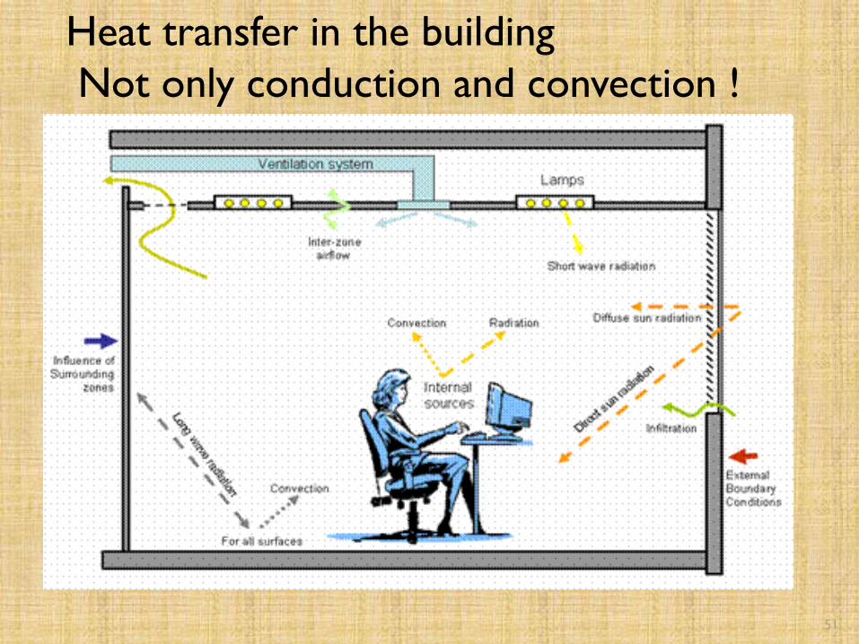
Heat transfer in the building
Not only conduction and convection !

COOLING LOAD IN BUILDING
• ROOF
• OPAQUE WALL
• GLASS
• INFILTRATION
• APPLIANCES AND LIGHTING FIGURES
• USER

53

54
55
Building Cooling and Heating
Requirements A function of three heat transfer components:
◦ Heat gains or losses through the building surfaces
[walls, fenestration, roof, etc.]
◦ Heat gains from internal heat producing sources
[lights, people, appliances, etc.]
◦ Heat gains or losses from infiltration of outdoor air
through window and door cracks, floors, walls, etc.

56
Indoor Design Conditions
The primary purpose of the heating and air-
conditioning system is to maintain the space in a
comfortable and healthy condition.
This is generally accomplished by maintaining the dry-
bulb temperature and the relative humidity within an
acceptable range.
The HVAC Applications Volume of the ASHRAE
Handbook gives recommendations for indoor design
conditions for specific comfort as well as industrial
applications.

Temperature Range :21-24 degree
centigrade
Relative Humidity 30 -70 %
Out side and Inside
A man in outdoor needs to adjust himself
with his clothing and whims of nature.
A man inside shelter – We can control his
comfort .
HOW ?
Comfort Zone for human being

58
Indoor Design Conditions…cont’d
ANSI / ASHRAE Standard 55-2004◦ “Thermal Environmental Conditions for Human
Occupancy” specifies the combinations of indoor
thermal environmental factors and personal factors that
produce acceptable conditions to a majority of the
occupants

59
Typical Brick Veneer Wall Section

The `U` factor is the rate at which heat is
transferred through a building barrier. It is
determined by the following equation.
U=1/(R1+R2+R3......Rn)
Where the `R` values are the resistance of
the various wall segments to the flow of
heat.
U = overall heat transfer coefficient, BTU/
hr· sf· ºF
R = thermal resistance, hr· sf· ºF /BTU
Transmission Coefficient(U-Factor)

61
Transmission Heat Loss Through Walls, Roofs, and Glass
H = U x A x ∆T
H = heat loss, BTU/hr
A = surface area of element, sf
U = overall heat transfer coefficient, BTU/ hr· sf· ºF
∆T = design dry bulb temperature difference between indoors
and outdoors, ºF
Cooling Load Temperature Difference (CLTD) Equivalent
temperature difference used for calculating the instantaneous
external cooling load across a wall or roof.

62
Transmission Heat Gain Through Walls and Roofs
H = U x A x ∆T
H = heat gain, BTU/hr
A = surface area of element, sf
U = overall heat transfer coefficient, BTU/ hr· sf· ºF
∆T = cooling load temperature difference, ºF

63
Conduction Heat Gains Through Glass
H = U x A x ∆T
H = heat gain, BTU/hr
A = surface area of element, sf
U = overall heat transfer coefficient, BTU/ hr· sf· ºF
∆T = cooling load temperature difference, ºF
Solar Heat Gain Through Glass
H = A x SC x SCL
H = heat gain, BTU/hr
SC = shading coefficient
SCL = solar cooling load factor
64
Infiltration Heat Gain and Heat Loss
The uncontrolled leakage of outdoor air into a
building through window and door cracks, floors,
walls, etc., as well as the flow of outdoor air into a
building through the normal use of exterior doors.
[Ex filtration is the leakage of indoor air out of the
building.The amount of ex filtration equals the
amount of infiltration]

65
Heat Gain from OccupantsActivity Typical Application Sensible
(BTU/hr)
Latent
(BTU/hr)
Seated at rest Theater 210 140
Seated, very light work Hotels, Apartments 230 190
Seated, eating Restaurant 255 325
Seated, light work Offices 255 255
Standing, walking slowly Retail store, bank 315 325
Light bench work Factory 345 435
Walking, light machine work Factory 345 695
Bowling Bowling alley 345 625
Heavy work, lifting Factory 565 1035
Heavy work Gymnasium 635 1165

66
Heat Gains from Lights
• Each watt of lighting load (including both lamp and ballast) releases
3.413 BTU/hr
Heat Gain from Motors
• Each brake or net horsepower of motor load divided by the
efficiency (including both motor and drive) releases 2545
BTU/hr
H = 2545 BTU/hr x Bhp / EffM x EffD
H = heat gain, BTU/hr
Bhp = brake horsepower
EffM = motor efficiency, decimal fraction, 0 – 1.0
EffD = drive efficiency, decimal fraction, 0 – 1.0

67
Heat Gains from Appliances and Equipment
Appliances and equipment (including food prep., hospital,
lab, office, etc.) normally produce significant sensible heat,
and may also produce significant latent heat.
To estimate the cooling load, specific heat gain data obtained
from the manufacturer is preferred. However, if it is not
available, recommended heat gains are published by
ASHRAE and other sources.
Evaluation of the operating schedule and the load factor for
each piece of equipment is essential.

68
Energy Saving Opportunities
Change indoor temperature and/or humidity
set-points
Improve building thermal envelope
◦ Apply additional thermal insulation
◦ Improve fenestration
◦ Reduce infiltration
Improve lighting system efficiency

Low-e coatings

Heating Load Calculation Procedure
A. Obtain building characteristics:
1. Materials
2. Size
3. Color
4. Shape
5. Location
6. Orientation, N, S, E,W, NE, SE, SW, NW, etc.
7. External shading
8. Occupancy type and time of day

B. Select outdoor design weather conditions:
1. Temperature.
2. Wind direction and speed.
3. Conditions in selecting outdoor design weather conditions:
a. Type of structure, heavy , medium or light.
b. Is structure insulated?
c. Is structure exposed to high wind?
d. Infiltration or ventilation load.
e. Amount of glass.
f. Time of building occupancy.
g. Type of building occupancy.
h. Length of reduced indoor temperature.
i. What is daily temperature range, minimum/maximum?
j. Are there significant variations from ASHRAE weather data?
k. What type of heating devices will be used?
l. Expected cost of fuel.

C. Select indoor design temperature to be maintained in each space.
Energy Conservation and Design Conditions, for code restrictions on selection of indoor design conditions.
D. Estimate temperatures in un-heated spaces.
E. Select and/or compute U-values for walls, roof, windows, doors, partitions, etc.
F. Determine area of walls, windows, floors, doors, partitions, etc.
G. Compute heat transmission losses for all walls, windows, floors, doors, partitions, etc.
H. Compute heat losses from basement and/or grade level slab floors.
I. Compute infiltration heat losses.
J. Compute ventilation heat loss required.
K. Compute sum of all heat losses indicated in items G, H, I, and J above.
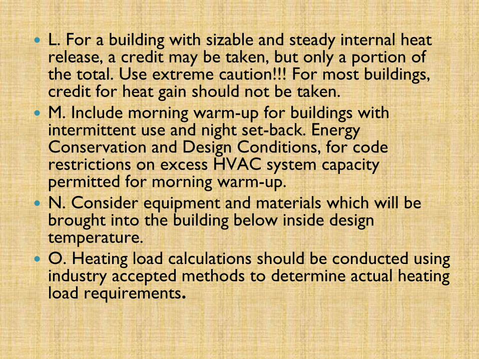
L. For a building with sizable and steady internal heat release, a credit may be taken, but only a portion of the total. Use extreme caution!!! For most buildings, credit for heat gain should not be taken.
M. Include morning warm-up for buildings with intermittent use and night set-back. Energy Conservation and Design Conditions, for code restrictions on excess HVAC system capacity permitted for morning warm-up.
N. Consider equipment and materials which will be brought into the building below inside design temperature.
O. Heating load calculations should be conducted using industry accepted methods to determine actual heating load requirements.

Example problem Calculate the cooling load for the building with the geometry shown on
figure. On east north and west sides are buildings which create shade on the whole wall.
Walls: 4” face brick + 2” insulation + 4” concrete block, U value = 0.1, Dark color
Roof: 2” internal insulation + 4” concrete , U value = 0.120 , Dark color
Below the building is basement with temperature of 75 F.
Internal design parameters:
air temperature 75 F
Relative humidity 50%
Find the amount of fresh air
that needs to be supplied by
ventilation system.
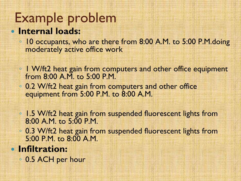
Example problem Internal loads:◦ 10 occupants, who are there from 8:00 A.M. to 5:00 P.M.doing
moderately active office work
◦ 1 W/ft2 heat gain from computers and other office equipment from 8:00 A.M. to 5:00 P.M.
◦ 0.2 W/ft2 heat gain from computers and other office equipment from 5:00 P.M. to 8:00 A.M.
◦ 1.5 W/ft2 heat gain from suspended fluorescent lights from 8:00 A.M. to 5:00 P.M.
◦ 0.3 W/ft2 heat gain from suspended fluorescent lights from 5:00 P.M. to 8:00 A.M.
Infiltration:◦ 0.5 ACH per hour

Example solutionFor which hour to do the calculation when you do manual calculation?
Identify the major single contributor to the cooling load and do the calculation for the hour when the maximum cooling load for this contributor appear.
For example problem major heat gains are
through the roof or solar through windows!
Roof: maximum TETD=61F at 6 pm (Total equivalent temperature differance)
South windows: max. SHGF=109 Btu/hft2 at 12 am (solar heat gain factor)
If you are not sure, do the calculation for both hours:
at 6 pmRoof gains = A x U x TETD = 900 ft2 x 0.12 Btu/hFft2 x 61 F = 6.6 kBtu/h
Window solar gains = A x SC x SHGF =80 ft2 x 0.71 x 10 Btu/hft2 = 0.6 kBtu/h total = 7.2 kBtu/h
at 12 am Roof gains = A x U x TETD = 900 ft2 x 0.12 Btu/hFft2 x 30 F = 3.2 kBtu/h
Window solar gains = A x SC x SHGF =80 ft2 x 0.71 x 109 Btu/hft2 = 6.2 kBtu/h total= 9.4 kBtu/h
For the example critical hour is July 12 AM.

How to calculate Cooling Load for HVAC
design
If the room with no outdoor influence has 4
lighting fixtures with 100 W each and 10
students,
what is the needed relative humidity and
temperature of supply air if only required
amount of fresh air is supplied
and room temperature is 75 F and RH 50%

"Rule of Thumb" Method
This method is simple to understand and use. However, it only
provides a rough guideline on the estimation of cooling load
requirement for the conventional window or split air-
conditioning system.
Procedures
a) Determine the function of the room (assuming there is no over-
crowding of occupants and / or heat generating equipments).
b) Measure the floor area (A) of the room in either in square feet or
square meter (a standard height of about 8.5 feet or 2.65 meter
between the floor and false ceiling shall be assumed for the
room).
c) Depending on whether you are using the imperial ( square feet )
or metric ( square meter ) system of measurement, decide on
which Factor (F) to use
78

79

80

81

82
INDOOR AIR QUALITY-ASHRAE STD. 62-1

83

84
AHSRAE Standard 62.1Ventilation for Acceptable Indoor Air Quality
Acceptable Indoor Air Quality:
Air in which there are no known
contaminants at harmful concentrations as
determined by cognizant authorities and
with which a substantial majority (80% or
more) of the people exposed do not
express dissatisfaction

85
The Purpose of Standard 62
The purpose of the Standard, first published in
1973 – “Standards for Natural and Mechanical
Ventilation”, has remained consistent:
“To specify minimum ventilation rates and
other measures intended to provide indoor air
quality that is acceptable to human occupants
and that minimizes adverse health effects.”

86
Under Continuous Maintenance…
The standard is updated on a regular bases using
ASHRAE’s Continuous Maintenance Procedures
◦ Continuously revised addenda are publicly reviewed
and approved by ASHRAE
◦ Published in a Supplement approximately 18 months
after each new edition of the Standard
OR
◦ A new, complete edition of the Standard is published
every three years

87
Significant Changes to ASHRAE Standard 62
1981 Edition:
◦ Reduced the minimum outdoor air requirements for ventilation
Office – 15 cfm/person to 5 cfm/person
1989 Edition:
◦ Increased minimum outdoor air requirements for ventilation [Response
to growing number of buildings with apparent IAQ problems]
Office – 5 cfm/person to 20 cfm/person
2004 Edition:
◦ Changed the ventilation rate procedure to include the summation of two
components: the occupant-density related component, and the area
related component
◦ Changed the ventilation rates in Table 6-1 to apply to non-smoking
spaces

88
Significant Changed … cont’d
2004 cont’d:
◦ Added classification of air with respect to contaminant and odor
intensity, and established guidelines for recirculation
2007 Edition:
◦ Updated information in Table 4-1 – “National primary ambient
air quality standards for outdoor air as set by the U.S.
Environmental Protection Agency”
◦ Added Section 5.18 – Requirements for buildings containing ETS
areas and ETS-free areas (ETS-Environmental Tobacco Smoke)

89
ASHRAE Standard 62.1
Two alternative procedures for determining
outdoor air intake rates:
◦ Ventilation Rate Procedure
This is a prescriptive procedure in which outdoor
air intake rates are determined based on space
type/application, occupancy level, and floor area
◦ IAQ Procedure
This is a design procedure in which outdoor air
intake rates and other system design parameters
are based on an analysis of contaminant
concentration targets, and perceived acceptability
targets

90

91
9262.1-2007

9362.1-2007

94NCSBC

95NCSBC
96
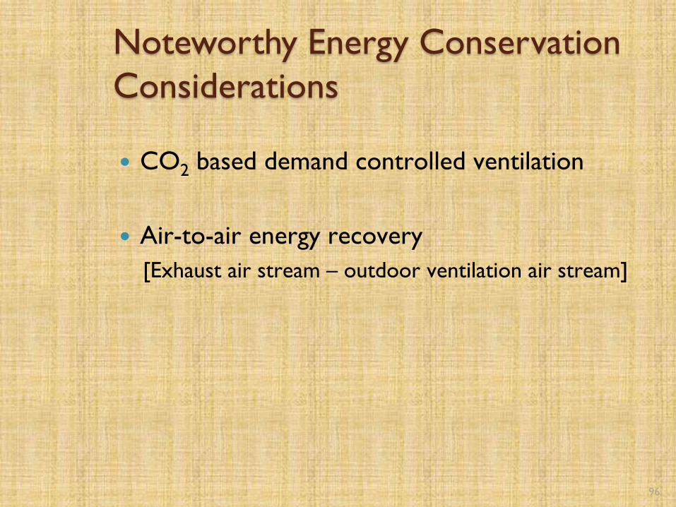
Noteworthy Energy Conservation
Considerations
CO2 based demand controlled ventilation
Air-to-air energy recovery
[Exhaust air stream – outdoor ventilation air stream]

97
Energy Conservation Imperative
Ongoing effective maintenance program for
equipment and controls

98
Commentary
ASHRAE Standard 62.1 – Code Adoption
◦ Standard 62.1 is voluntary until adopted by code or
other regulation
◦ Code adoption is often delayed due to time required
to be accepted and integrated into the model codes,
as then accepted and adopted by the local codes

99
Energy Saving Opportunities
Optimize the energy requirements
associated with outdoor ventilation air
Apply CO2 based demand control
Apply air-to-air energy recovery equipment

100
VAPORCOMPRESSION REFRIGERATION CYCLE

101
Vapor Compression
Refrigeration Cycle
Evaporation: Low pressure liquid absorbs
heat (heat source) and changes state to a low
pressure vapor
Compression: Low pressure vapor is
compressed to high pressure vapor
Condensation: High pressure vapor is cooled
(heat sink) and changes state to a high pressure
liquid
Expansion: High pressure liquid is reduced to
low pressure liquid via throttling

102
Vapor Compression
Refrigeration Cycle Components
EVAPORATOR

103
Basic Liquid Chiller - Water Cooled
EVAPORATOR
CHILLED WATER

ENERGY USAGE
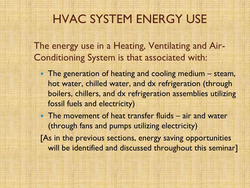
HVAC SYSTEM ENERGY USE
The energy use in a Heating, Ventilating and Air-
Conditioning System is that associated with:
The generation of heating and cooling medium – steam,
hot water, chilled water, and dx refrigeration (through
boilers, chillers, and dx refrigeration assemblies utilizing
fossil fuels and electricity)
The movement of heat transfer fluids – air and water
(through fans and pumps utilizing electricity)
[As in the previous sections, energy saving opportunities
will be identified and discussed throughout this seminar]

HVAC SYSTEMS
106
107
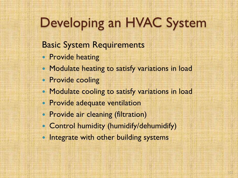
Developing an HVAC System
Basic System Requirements
Provide heating
Modulate heating to satisfy variations in load
Provide cooling
Modulate cooling to satisfy variations in load
Provide adequate ventilation
Provide air cleaning (filtration)
Control humidity (humidify/dehumidify)
Integrate with other building systems

108
Developing an HVAC System
Critical Consideration Issues Environmental Control Requirements
◦ Occupant Comfort
◦ Clean Air / Ventilation
◦ Product / Process Requirements
Equipment Fuctionality
◦ Reliability while meeting requirements
Economics
◦ Initial Cost
◦ Operating Cost
◦ Maintenance Cost

109
HVAC System General Classification
All-Air Systems
Air-and-Water Systems
All-Water Systems
Unitary Air Conditioners

110
HVAC System Definitions
All-Air System◦ Provides complete sensible and latent cooling capacity in the
cold air supplied by the system
◦ No additional cooling is required at the zone
◦ Heating can be accomplished by the same airstream, either in
the central system or at a particular zone
Air-and-Water System◦ Conditions the spaces by distributing air and water sources to
terminal units installed in habitable space throughout a building
◦ The air and water are cooled or heated in central mechanical
equipment rooms
◦ The air supplied is called primary air, the water supplied is called
secondary water
111
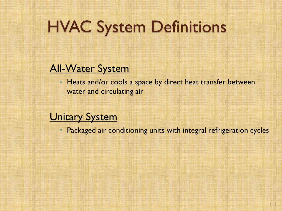
HVAC System Definitions
All-Water System◦ Heats and/or cools a space by direct heat transfer between
water and circulating air
Unitary System◦ Packaged air conditioning units with integral refrigeration cycles

112
All-Air Systems
Single zone draw-through
Constant volume terminal reheat
Dual-duct
Multizone
Variable air volume (VAV)

113
General Air Handling System Layout

Air Side Economizer
Modes:
Free Cooling
Economy Refrigeration
114

115
Constant Volume System with Terminal
Reheat

116
Dual Duct System

117
Variable Air Volume System (VAV)

118
True VAV Terminal Unit

119
Parallel Fan-Powered VAV Terminal Unit

120
Series Fan-Powered VAV Terminal
Unit


122
Fan Volume Modulation for VAV
Systems
123
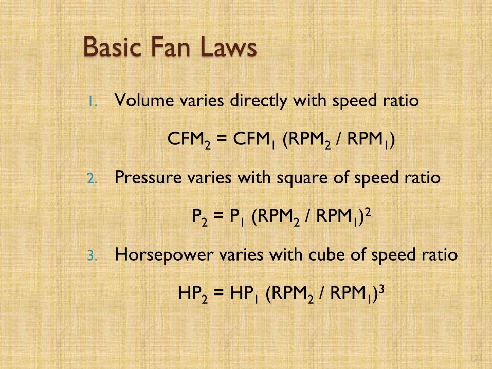
Basic Fan Laws
1. Volume varies directly with speed ratio
CFM2 = CFM1 (RPM2 / RPM1)
2. Pressure varies with square of speed ratio
P2 = P1 (RPM2 / RPM1)2
3. Horsepower varies with cube of speed ratio
HP2 = HP1 (RPM2 / RPM1)3

124
Fan Problem
An existing centrifugal supply air fan serving a central station air washer delivers 90,000 cfm @ 2” s.p. (wg), 825 rpm and 47.3 bhp.
It has been established that the volumetric air flow rate (cfm) can be reduced 20% because of excessive design safety factors and plant production equipment modifications.
Determine: 1) new air volume, 2) rpm @ new cfm, 3) bhp @ new cfm, and 4) annual electrical savings
Electricity cost:Demand charge - $6.00/kw (avg)Energy charge - $0.031/kwh (avg)

125
Fan Problem Solution1. New Air Volume = 0.8 x 90,000 = 72,000 cfm
2. New RPM = 825 (72,000/90,000) = 660 rpm
3. New HP = 47.3 (660/825)3 = 24.2 hp
4. Annual electrical savings…
HP reduction = 47.3 – 24.2 = 23.1 hp
KW reduction = (23.1 hp)(0.746 kw/hp) = 17.2 kw
Energy:
(23.1 hp)(0.746 kw/hp)(8760 hr/yr)($0.031/kwh)(1.03 tax)
= $4,820 /yr
Demand:
(17.2 kw/mo)(12 mo/yr)($6.00/kw)(1.03 tax)
= $1,276 /yr
Annual Electrical Savings:
$4,820 + $1,276 = $6,096 /yr

126
Air and Water System
Induction
Fan Coil

127
Induction Unit
Induction Nozzle
128
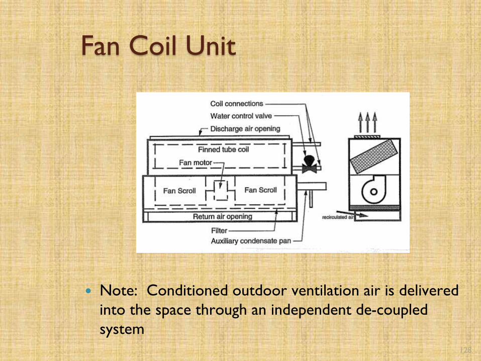
Fan Coil Unit
Note: Conditioned outdoor ventilation air is delivered
into the space through an independent de-coupled
system

129
All-Water Systems
Unit Ventilator
Fan Coil
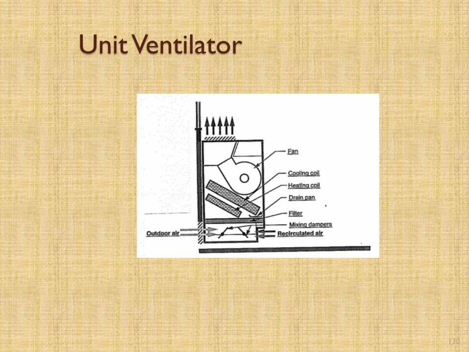
130
Unit Ventilator

131
Fan Coil Unit
Note: Outdoor ventilation air provided through
infiltration

132
Unitary Air Conditioners
Rooftop
Split System
Through-the-wall

133
Packaged Rooftop Air Conditioning Units

134
Water-Source Heat Pumps

135
Water Loop Heat Pump System

Energy Saving Opportunities
Convert air-handling systems from constant volume to
variable-air-volume (VAV) airflow: employ VAV boxes and
fan motor variable speed drives. [Typical target systems:
constant volume systems with terminal reheat, & dual
duct systems]
Convert traditional multi-zone units to by-pass multi-zone
units
Install air-side economizers – maximize the use of
outdoor air for cooling: “free-cooling” and “economy
refrigeration”
Eliminate the air-side economizer cycle on multi-zone units
Install water-side economizers
136

Energy Saving Opportunities… cont’d
Optimize/balance volumetric airflow rates and eliminate
excess by fan speed adjustments
Implement occupied/unoccupied scheduling
Employ air-to-air heat exchangers – exhaust air heat
recovery
Develop and implement an effective Preventative
Maintenance (PM) program
Replace equipment with higher efficiency equipment.
[Evaluate the employment of evaporative condensers in lieu
of air-cooled condensers]

138
Air-to-Air Heat Recovery
Properly applied air-to-air energy recovery equipment, which transfers energy between supply and exhaust airstreams, will reduce building and/or process energy usage in a cost-effective manner.
Air-to-air energy recovery applications fall into three categories (ASHRAE):
◦ Comfort-to-comfort
◦ Process-to-comfort
◦ Process-to-process
[Because of time constraints in this workshop, we will limit our discussion to comfort-to-comfort applications]

139
Comfort-to-Comfort Applications
Sensible Heat Devices - only transfer sensible heat
between the supply and exhaust airstreams, except
when the exhaust airstream is cooled to below its dew
point.
Total Heat Devices - transfer both sensible and latent
heat between the supply and exhaust airstreams
140
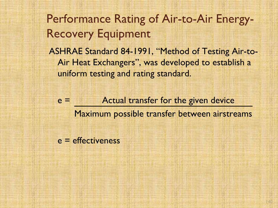
Performance Rating of Air-to-Air Energy-
Recovery Equipment
ASHRAE Standard 84-1991, “Method of Testing Air-to-
Air Heat Exchangers”, was developed to establish a
uniform testing and rating standard.
e = Actual transfer for the given device
Maximum possible transfer between airstreams
e = effectiveness

141
Air-to-Air Heat Recovery
Equipment
Rotary (Heat Wheel)
Heat Pipe
Static Heat Echanger
Runaround System

142
Rotary (Heat Wheel)

143
Heat Pipe

144
Static Heat Exchangers

145
Runaround System

CONTROL STRATEGY
146

Control Strategy
Optimize the operation of the HVAC systems
[To minimize the fan, heating and cooling energy requirements]
Develop and implement system scheduling –
occupied/unoccupied
Implement optimal start/stop
Optimize the temperature and/or humidity setpoints in both
the occupied and unoccupied periods
Introduce outdoor ventilation air only when the building is
occupied
Provide control system override
147


2
In the early 1900’s, there was a young engineer
Working For Buffalo Forge Company that received
a 'flash of genius' while waiting for a train.
It was a foggy night and he was going over in his
mind the problem of temperature and humidity
control. By the time the train arrived, Carrier had
an understanding of the relationship between
temperature, humidity and dew point.
That young engineer was…
…Willis H. Carrier

3
What Mr. Carrier’s 'flash of genius' that day came to be known as Psychrometry...
…the study of air and
water vapor in mixture.

COMFORT
• Comfort describes a delicate balance of pleasant feelings in the body produced by its surrounding
• Comfort involves
– Temperature
– Humidity
– Air movement
– Air cleanliness
• The human body makes adjustments to comfort conditions by its circulatory and respiratory systems

FOOD, ENERGY, AND THE BODY
• The body uses food to produce energy
• The body energy
– Some stored as fatty tissue
– Some leaves as waste
– Some leaves as heat
– Some is used to keep the body functioning

BODY TEMPERATURE
• Humans are comfortable when the heat is transferring to the surroundings at the correct rate
• The body gives off and absorb heat by conduction, convection and radiation
• Surroundings must be cooler than the body for the body to be comfortable
• The body is close to being comfortable when it is at rest and in surroundings of 75 F and 50% humidity with slight air movement
• Comfort conditions in winter and in summer are different

AMBIENT TEMPERATURE 75°F at
50% HUMIDITY
BODY TEMPERATURE OF 98.6°F
Heat travels from the body to the ambient
air

Outside ambient temperature
100°F
The body cannot give up heat readily
THE COMFORT CHART
• Can be used to compare one comfort situation or condition with another
• Shows the different combinations of temperature and humidity for summer and winter
• The closer the plot falls to the middle of the chart, the more people would be comfortable
• Different charts for summer and winter conditions

10
Psychrometric
Chart...
…graphically shows
the Properties of Air.

11
Psychrometric
Chart used...
…to model conditions
inside buildings by
system designers.

12
Psychrometric
Chart used...
…to monitor conditions in
commercial refrigeration
plants and manufacturing
environments.

13
Psychrometric
Chart used...
…to evaluate problems
in air conditioned
environments.

14
SOLE
H
E
E
L
Structure…

15
1
2
34
5
6
7
Seven Properties of Air

16
Seven Properties of Air...
Dry bulb temperature …taken
with a standard thermometer.
SOLE 800 F DB
0F

Dry Bulb Temperature
• Measured with a dry-bulb thermometer
• Measures the level of heat intensity of a substance
• Used to measure and calculate sensible heat and changes in sensible heat levels
• Does not take into account the latent heat aspect
• Room thermostats measure the level of heat intensity in an occupied space

DRY-BULB TEMPERATURE SCALE
DRY-BULB TEMPERATURE
As we move up and down, the
dry bulb temperature does not
changeAs we move from left to
right, the dry bulb
temperature increases
As we move from right
to left, the dry bulb
temperature decreases
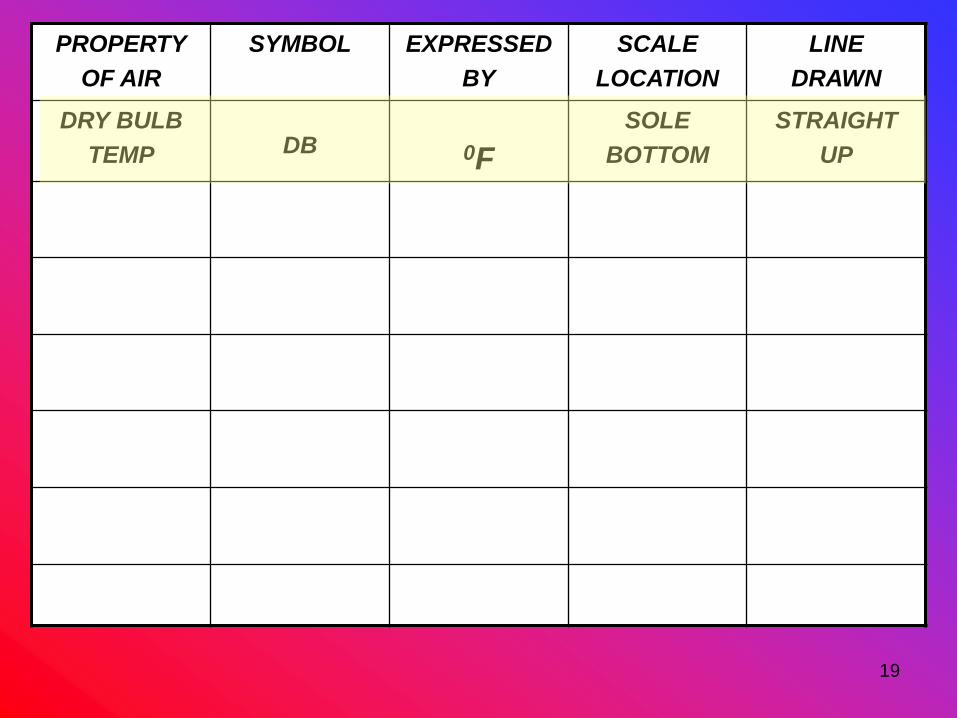
19
PROPERTY
OF AIR
SYMBOL EXPRESSED
BY
SCALE
LOCATION
LINE
DRAWN
DRY BULB
TEMP DB 0F
SOLE
BOTTOM
STRAIGHT
UP

20
Seven Properties of Air...
2. Wet Bulb Temperature
…taken with a thermometer
with a wetted wick.
Instep
660 F WB
SLING
PSYCHROMETER

Wet Bulb Temperature
• Measured with a wet-bulb thermometer
• Temperature reading is affected by the
moisture content of the air
• Takes the latent heat aspect into account
• Used in conjunction with the dry-bulb
temperature reading to obtain relative
humidity readings and other pertinent
information regarding an air sample

WET-BULB TEMPERATURE SCALE
As we move up and down along a
wet-bulb temperature line, the
wet bulb temperature does not
change
The red arrow indicates an
increase in the wet bulb
temperature reading
The blue arrow
indicates a decrease
in the wet bulb
temperature reading

DRY-BULB TEMPERATURE
WET-BULB, DRY-BULB COMBO

24
PROPERTY
OF AIR
SYMBOL EXPRESSED
BY
SCALE
LOCATION
LINE
DRAWN
DRY BULB
TEMP DB 0F
SOLE
BOTTOM
STRAIGHT
UP
WET BULB
TEMP WB 0F INSTEP SLANTED

25
Seven Properties of Air...
3.Dew Point Temperature
…temperature at which
moisture condenses on
a surface.

26
PROPERTY
OF AIR
SYMBOL EXPRESSED
BY
SCALE
LOCATION
LINE
DRAWN
DRY BULB
TEMP DB 0F
SOLE
BOTTOM
STRAIGHT
UP
WET BULB
TEMP WB 0F INSTEP SLANTED
DEW POINT
TEMP DP 0F INSTEP
HORIZONTAL
TO LEFT

DEW POINT TEMPERATURE
• The temperature at which the moisture in the air begins to condense out of the air
• The temperature at which water forms on objects from the air is called the dew point temperature of the air
• The evaporator in an air conditioning or refrigeration system operates below the dew point temperature, so, as air comes in contact with the coil, moisture begins to condense out of the air

Glass of ice water (45°F)
Dew point temperature of the surrounding air 55°F
Droplets of moisture begin to form on the surface of the glass

29
Seven Properties of Air...
4. Specific Humidity
Absolute Humidity or Humidity
Ratio
…amount of water vapor in
dry air. Measured in grains
per pound of dry air.
77 gr/lb
Heel

30
PROPERTY
OF AIR
SYMBOL EXPRESSED
BY
SCALE
LOCATION
LINE
DRAWN
DRY BULB
TEMP DB 0F
SOLE
BOTTOM
STRAIGHT
UP
WET BULB
TEMP WB 0F INSTEP SLANTED
DEW POINT
TEMP DP 0F INSTEP
HORIZONTAL
TO LEFT
SPECIFIC
HUMIDITY W GR/LB
HEEL
RIGHT VERT
HORIZONTAL
TO RIGHT

---- HUMIDITY ----
ABSOLUTELY RELATIVE
• There are two types of humidity
– ABSOLUTE
– RELATIVE
• “AH” and “RH” are not the same
• Cannot be used interchangeably
• All humidities are not created equal

ABSOLUTE HUMIDITY
• Amount of moisture present in an air
sample
• Measured in grains per pound of air
• 7,000 grains of moisture = 1 pound
1 POUND
60
GRAINS

The moisture scale on the
right-hand side of the chart
provides information regarding
the absolute humidity of an air
sample

MOISTURE CONTENT SCALE
As we move from side to
side, the moisture content
does not change
As we move up, the moisture
content increases
As we move down, the
moisture content decreases
MO
IST
UR
E C
ON
TE
NT
(BT
U/L
BA
IR)
35
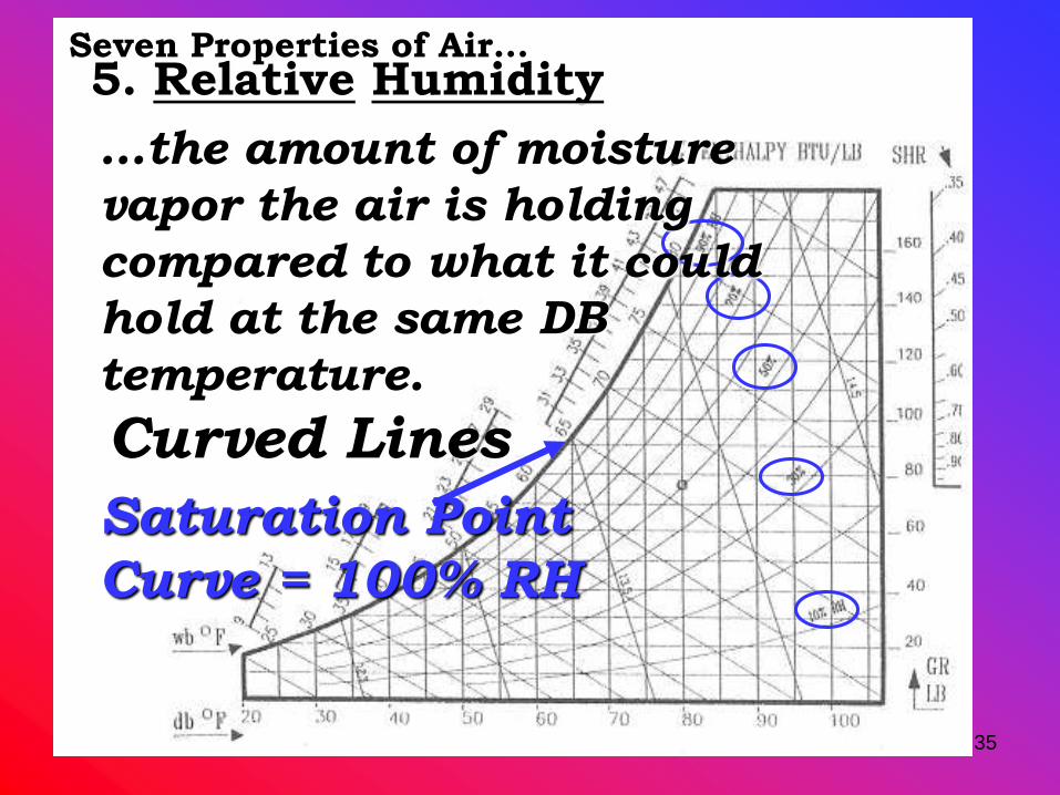
5. Relative HumiditySeven Properties of Air...
Curved Lines
Saturation Point
Curve = 100% RH
…the amount of moisture
vapor the air is holding
compared to what it could
hold at the same DB
temperature.

RELATIVE HUMIDITY
• Amount of moisture present in an air sample
relative to the maximum moisture capacity of
the air sample
• Expressed as a percentage
• Can be described as the absolute humidity
divided by the maximum moisture-holding
capacity of the air

RELATIVE HUMIDITY Example #1
HOW FULL IS THE PARKING
LOT?
% FULL = # of CARS
# of SPACESX 100% % FULL =
10 CARS
20 SPACESX 100%
% FULL = 0.5 X 100%

RELATIVE HUMIDITY Example #2

RELATIVE HUMIDITY Example #3
60
GRAINS
If capacity is 120 grains, then the relative humidity
will be:
RH = (60 grains ÷ 120 grains) x 100% =
50%

RELATIVE HUMIDITY SCALE
As we move along a relative
humidity line, the relative
humidity remains the same
As we move up, the relative
humidity increases
As we move down, the
relative humidity decreases

41
PROPERTY
OF AIR
SYMBOL EXPRESSED
BY
SCALE
LOCATION
LINE
DRAWN
DRY BULB
TEMP DB 0F
SOLE
BOTTOM
STRAIGHT
UP
WET BULB
TEMP WB 0F INSTEP SLANTED
SPECIFIC
HUMIDITY W GR/LB
HEEL
RIGHT VERT
HORIZONTAL
TO RIGHT
DEW POINT
TEMP DP 0F INSTEP
HORIZONTAL
TO LEFT
RELATIVE
HUMIDITY RH %RH CURVED CURVED

42
Seven Properties of Air...
6. Specific Volume
- Steeply slanted lines- Expressed in Cubic Feet
per Pound ( ft3/lb )
- Space that one pound of
dry air takes up

SPECIFIC VOLUME & DENSITY
• Specific volume and density are reciprocals
of each other
• Density = lb/ft3
• Specific volume = ft3/lb
• Density x Specific Volume = 1
• Specific volume can be determined from the
psychrometric chart, density must be
calculated

LINES OF SPECIFIC VOLUME
As we move along a line of
constant specific volume, the
specific volume remains
unchanged
As we move to the right, the
specific volume increases
As we move to the left,
the specific volume
decreases

45
PROPERTY
OF AIR
SYMBOL EXPRESSED
BY
SCALE
LOCATION
LINE
DRAWN
DRY BULB
TEMP DB 0F
SOLE
BOTTOM
STRAIGHT
UP
WET BULB
TEMP WB 0F INSTEP SLANTED
SPECIFIC
HUMIDITY W GR/LB
HEEL
RIGHT VERT
HORIZONTAL
TO RIGHT
DEW POINT
TEMP DP 0F INSTEP
HORIZONTAL
TO LEFT
RELATIVE
HUMIDITY RH %RH CURVED CURVED
SPECIFIC
VOLUME V FT3/LB
STEEPLY
SLANTED
STEEPLY
SLANTED

46
Seven Properties of Air...
7. Enthalpy
- Total amount of heat
energy (sensible and
latent) in one pound
of air.
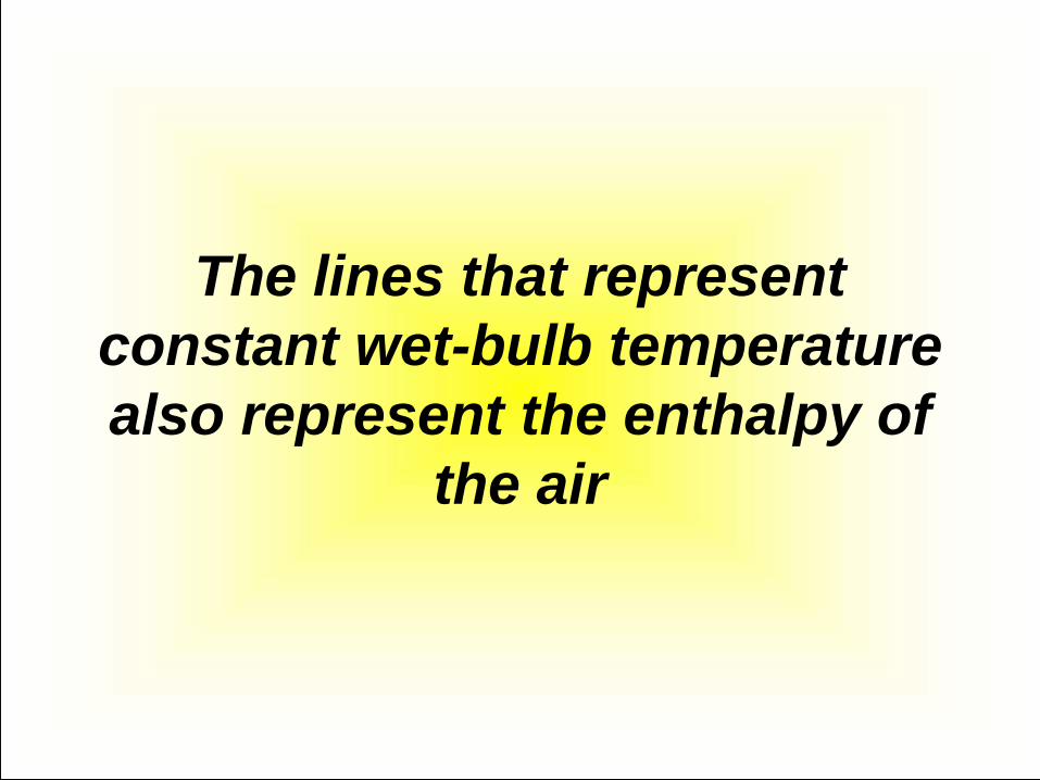
The lines that represent
constant wet-bulb temperature
also represent the enthalpy of
the air

ENTHALPY SCALE
As we move up and down
along an enthalpy line, the
enthalpy does not change
The red arrow
indicates an increase
in enthalpy
The blue arrow
indicates a decrease
in enthalpy

49
PROPERTY
OF AIR
SYMBOL EXPRESSED
BY
SCALE
LOCATION
LINE
DRAWN
DRY BULB
TEMP DB 0F
SOLE
BOTTOM
STRAIGHT
UP
WET BULB
TEMP WB 0F INSTEP SLANTED
SPECIFIC
HUMIDITY W GR/LB
HEEL
RIGHT VERT
HORIZONTAL
TO RIGHT
DEW POINT
TEMP DP 0F INSTEP
HORIZONTAL
TO LEFT
RELATIVE
HUMIDITY RH %RH CURVED CURVED
SPECIFIC
VOLUME V FT3/LB
STEEPLY
SLANTED
STEEPLY
SLANTED
ENTHALPY H BTU/LB ABOVE
INSTEP
EXTENSION
OF WB LINE

50
X
Making a Sling Psychrometer for reading WB: Need: 1 ea. Athletic Shoe Lace
Cut Shoe Lace
Poke Pocket Thermometer into long piece of Shoe Lace
Short piece taped or rubber-banded to Thermometer
To use: Wet short end and sling while holding on to long end.


RETURN
AIRSUPPLY
AIR
Return Air: 75ºFDB,
50% r.h.
Supply Air: 55ºFDB,
90% r.h.
Airflow: 1200 cfm

RETURN
AIRSUPPLY
AIR
Return Air: 75ºFDB,
50% r.h.Supply Air: 55ºFDB, 90% r.h.
Airflow: 1200 cfm
55ºF 75ºF
ΔT = Return Air Temp – Supply Air
Temp
ΔT = 75ºF - 55ºF = 20ºF
64
grains/lb
60
grains/lb
h = 28.1 btu/lbAIR
h = 21.6 Btu/lbAIR
ΔW = Return grains/lbAIR – Supply
grains/lbAIR
ΔW = 64 Grains – 60 Grains = 4 grains/lbAIR
Δh = Return btu/lbAIR – Supply btu/lbAIR
Δh = 28.1 btu/lbAIR - 21.6 btu/lbAIR = 6.5
btu/lbAIR

54

55
RASA
Blower Section
Heat
Section
TransitionEvap Coil
Air Conditioning Processes...
Psychrometric
changes take
place between
RA and SA
Return Air
Plenum
Supply Air
Plenum
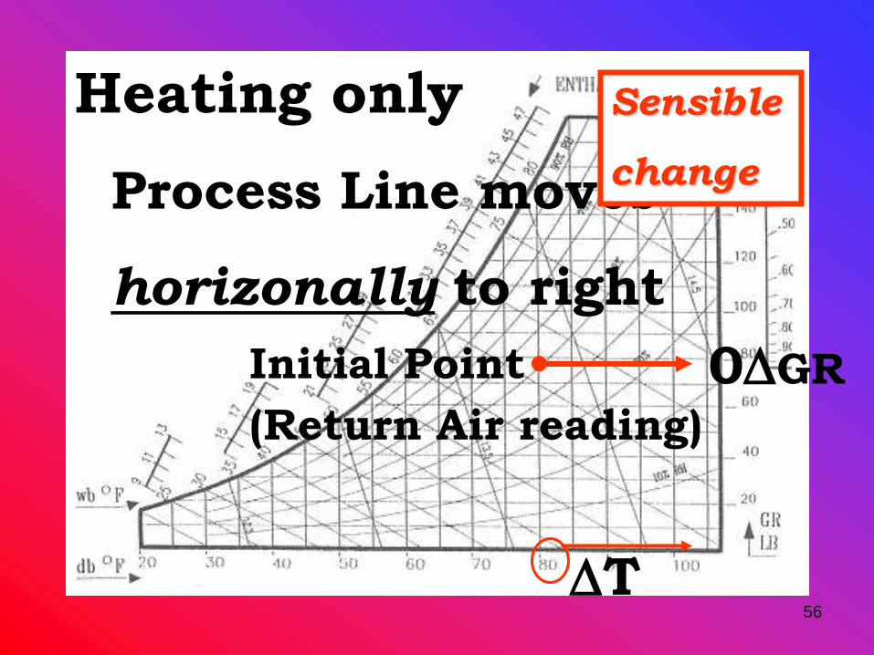
56
Initial Point
(Return Air reading)
Process Line moves
horizonally to right
DT
0DGR
Heating only Sensible
change

57
Process Line moves
horizonally to left
DT
0DGR
Cooling only Sensible
change

58
Process Line moves
straight up
0DT
DGR
Humidifying only
Latent
change
59
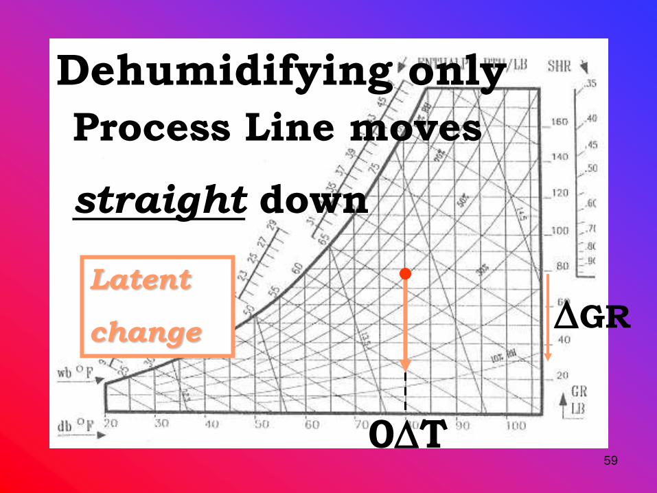
Process Line moves
straight down
0DT
DGR
Dehumidifying only
Latent
change

60
Other AC Processes...
Heating &
Humidifying
Heating &
Dehumidifying
Cooling &
Humidifying
Cooling &
Dehumidifying
Sensible and Latent change

Prof. Koldenhott's FUNdamentals
of Cocktailmetrics
61DT
DGR
DH
800 F DB600 F DB
50% RH
80% RH
What we need
for evaluating
AC Processes...
RA
SA

AIR FORMULAE
QL = 0.68 x Cfm x ΔW
QT = QS + QL
QT = 4.5 x Cfm X Δh
Qs = 1.1 x Cfm X ΔT

63
Air Side EquationsSensible Load:
Qs = 1.1 X CFM X DT
A constant based
on the Density of
Air and a time
conversion factor
Determined from
the Condensing
Unit model number
QS is expressed in BTUH

64
Air Side Equations
Latent Load:
QL = .68 X CFM X DGR
QL is expressed in BTUH
A constant…
including a time
conversion factor
Same as that used
for QS

65
Air Side Equations
Total Load:
QT = 4.45 X CFM X DH
A constant…
including a time
conversion factor
Same as that used
for QS
QT is expressed in BTUH

66

67
Sensible Heat
Ratio…
…the ratio of Sensible
Load (QS) to
Total Load (QT)
LATENT SENSIBLE

68
Sensible Heat
Ratio…
SHR = QS
QT

69
Sensible Heat Ratio…
SHR = 29,060 btuh
36,325 btuh
Example:
=
.80 SHR
Prof. Koldenhott's FUNdamentals
of Cocktailmetrics
70
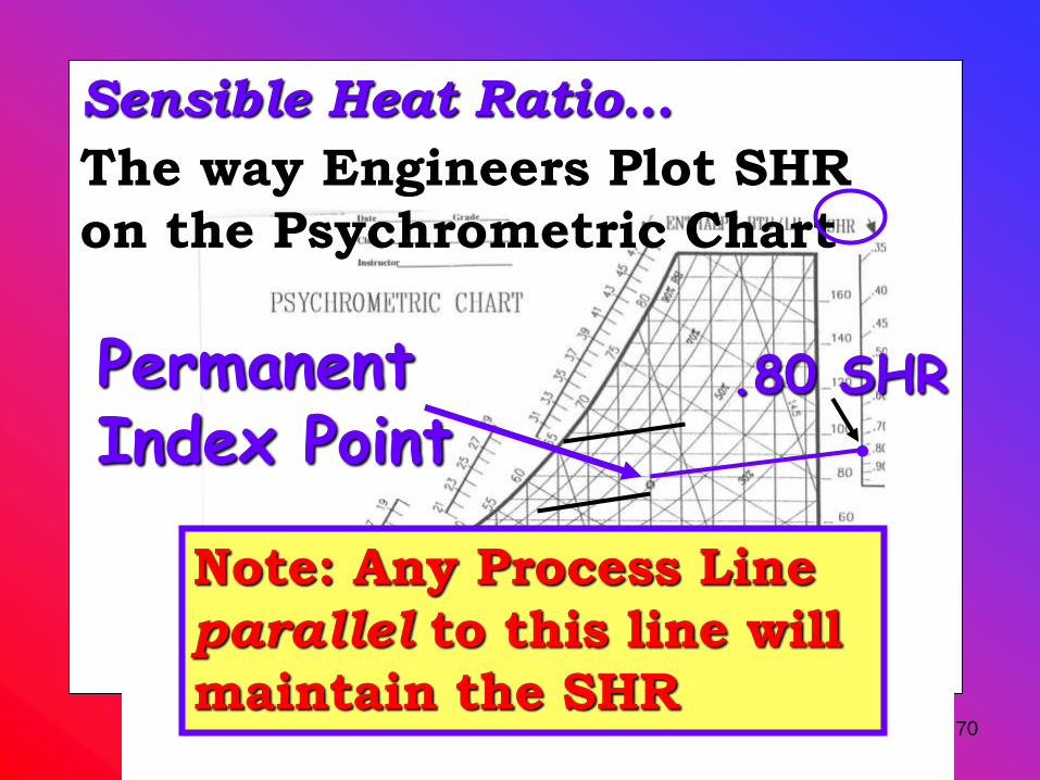
Sensible Heat Ratio…
The way Engineers Plot SHR
on the Psychrometric Chart
Permanent Index Point
.80 SHR.
Note: Any Process Line
parallel to this line will
maintain the SHR

71
Hs
HL
…Sensible
change in
Enthalpy
…Latent
change in
Enthalpy
DT
Sensible change…
DGR
Latent
change…

RETURN AIR SUPPLY AIR
Water Vapor at 75ºF
Water at
50ºF

TOTAL HEAT
• The capacity of a heating and cooling unit may be field checked with the total heat feature of the psychrometric chart
• Total heat = sensible heat + latent heat
• Sensible heat formula: Qs = 1.08 x cfm x ∆T
• Total heat formula: Qt = 4.5 x cfm x total heat difference
• CFM formula: ______Qs______
1.08 x ∆T

SUMMARY
• Comfort is affected by air movement, humidity, air cleanliness and temperature
• Humans are considered to be comfortable when heat is transferred from the body to its surroundings at the proper rate
• The body is close to being comfortable when it is at rest and in surroundings of 75°F and 50% humidity with slight air movement
• The comfort chart is used to compare one comfort situation or condition with another

SUMMARY
• Psychrometrics is the study of air and its properties
• Density indicates how many pounds one cubic foot of a substance weighs
• Specific volume is the reciprocal of density
• Moisture in air is referred to as humidity
• Dry bulb temperature is the sensible heat level of air
• Wet bulb temperatures take the moisture content of the air into account

SUMMARY
• The dew point temperature is the point at which moisture in the air begins to condense out of the air
• The psychrometric chart provides a graphical representation of an air sample as well as a means to calculate other properties of the air
• Total heat = sensible heat + latent heat

LAW OF THE TEE FOR MIXED AIR
AIR
HANDLEROUTSIDE AIR
RETURN AIR
MIXED
AIR

LAW OF THE TEE FOR MIXED AIR
PERCENTAGE OF RETURN AIR +
PERCENTAGE OF OUTSIDE AIR
100% of MIXED AIR
OUTSIDE
RETURN

LAW OF THE TEE FOR MIXED AIR
SAMPLE PROBLEM
AIR CONDITIONS: RETURN AIR (80%): 75ºFDB, 50%RH
OUTSIDE AIR (20%): 85ºFDB, 60%RH
MIXED AIR = 80% RETURN AIR + 20% OUTSIDE AIR
MIXED AIR = (.80) RETURN AIR + (.20) OUTSIDE AIR
MIXED AIR = (.80) (75ºFDB, 50%RH) + (.20) (85ºFDB, 60%RH)
MIXED AIR = 60ºFDB, 40%RH + 17ºFDB, 12%RH
MIXED AIR = 77ºFDB, 52%RH

Return Air: 75ºFDB,
50% r.h.
Outside Air: 85ºFDB,
60% r.h.
Mixed Air: 77ºFDB, 52%
r.h.
RETURN AIR
OUTSIDE AIR
MIXED AIRSUPPLY AIR

Heat/cooling load calculations

Principles of Heat Transfer
Heat energy cannot be destroyed
Heat always flows from a higher temperature substance to a lower
temperature substance.
Heat can be transferred from one substance to another

3 Basic principles of heat transfer
1.Heat energy cannot be destroyed; it can only be transferred to another substance-principle of "conservation of energy.
2) Heat energy naturally flows from a higher-temperature substance to a lower-temperature substance, in other words, from hot to cold.
3) Heat energy is transferred from one substance to another by one of three basic processes: conduction, convection, or radiation.

Methods of Heat Transfer

Sensible heat is heat energy that, when added to or removed from a substance, results in a measurable change in dry-bulb temperature.
Changes in the latent heat content of a substance are associated with the addition or removal of moisture.
Latent heat can also be defined as the “hidden” heat energy that is absorbed or released when the phase of a substance is changed.
For example, when water is converted to steam, or when steam is converted to water.

Heat Generated by People

Factors Affecting Human Comfort
Dry-bulb temperature
Humidity
Air movement
Fresh air
Clean air
Noise level
Adequate lighting
Proper furniture and
work surfaces

Indoor Design Conditions

Cooling Load Componentsroof
lights
equipment
floor
exteriorwall
glass solar
glassconduction
infiltrationpeople
partitionwall

Sensible and Latent Gains
sensibleload
latentload
conduction through roof, walls, windows,and skylights
solar radiation through windows, skylights
conduction through ceiling, interior partition walls, and floor
people
lights
equipment/appliances
infiltration
ventilation
system heat gains
cooling load components

Time of Peak Cooling Loadh
eat
gain
roofeast-facing
window
12 6 12 6 12noona.m. p.m. midmid
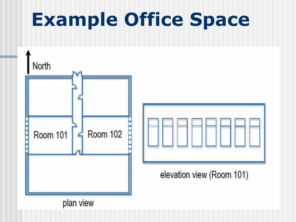
Example Office Space

The windows face west and the solar heat gain through these windows will peak in the late afternoon when the sun is setting and shining directly into the windows. Because of this, we will assume that the maximum cooling load for our example
space occurs at 4 p.m.
Basis for estimating the space cooling and heating loads.
Open-plan office space located in a single-story office building
Floor area = 45 ft x 60 ft
Floor-to-ceiling height = 12 ft (no plenum between the space and roof).
Desired indoor conditions = 78ºF [25.6ºC] dry-bulb temperature, 50% relative humidity during cooling season;
72ºF [22.2ºC] dry-bulb temperature during heating season.
West-facing wall, 12 ft high x 45 ft long constructed of 8 in. [203.2 mm] lightweight concrete

Block with aluminum siding on the outside, 3.5 in. [88.9 mm] of insulation, and ½ in. [12.7 mm] gypsum board on the inside.
Eight clear, double-pane (¼ in. [6.4 mm]) windows mounted in aluminum frames. Each window is 4 ft wide x 5ft high
Flat, 45 ft x 60 ft roof constructed of 4 in. [100 mm] concrete with 3.5 in. [90 mm] insulation & steel decking.
Space is occupied from 8:00 a.m. until 5:00 p.m. by 18 people doing moderately active work.
Fluorescent lighting in space = 2 W/ft2
Computers and office equipment in space = 0.5 W/ft2, plus one coffee maker.
In order to simplify this example, we will assume that, with the exception of the west-facing exterior wall, room
Room is surrounded by spaces that are air conditioned to the same temperature as this space.

Outdoor Design Conditions
0.4%, means that the dry-bulb temperature in St. Louis exceeds 95ºF [35ºC] for only 0.4% of all of the hours in an average year. Also, 76ºF [25ºC] is the wet-bulb temperature that occurs most frequently when the dry-bulb temperature is 95ºF [35ºC].

Heat Conduction through Surfaces
Conduction is the process of transferring heat through a solid, such as a wall, roof, floor, ceiling, window, or skylight. Heat naturally flows by conduction from a higher temperature toa lower temperature.

Conduction through a Shaded Wall
Q = U × A × ΔT
where,
Q = heat gain by conduction, Btu/hr
U = overall heat-transfer coefficient of the surface, Btu/hr•ft2•°F
A = area of the surface, ft2
ΔT = dry-bulb temperature difference across the surface, ºF

U-factor

U-factor for Example Wall

The U-factor of this wall is calculated by summing the thermal resistances of each of these layers and then taking the inverse.
The U-factor of the roof

Conduction through a Shaded Wall
Qwall = 0.06 × 380 × (95 – 78) = 388 Btu/hr
Conduction heat gain through the west-facing wall (assume shaded at all times):
U-factor = 0.06 Btu/hr•ft2•°F
Total area of wall + windows = 12 ft x 45 ft = 540 ft2
Area of windows = 8 windows x (4 ft x 5 ft) = 160 ft2
Net area of wall = 540 – 160 = 380 ft2
ΔT = outdoor temperature (95ºF)– indoor temperature 78ºF

Sunlit Surfacessun
rayssolar angle changes throughout the day
When the sun’s rays strike the surface at a 90º angle, the maximum amount of radiant heat energy is transferred to that surface. When the same rays strike that same surface at a lesser angle, less radiant heat energy is transferred to the surface.

Time Lagso
lar
eff
ec
t
12 6 12 6 12noona.m. p.m. midmid
AB
time lagCurve A shows themagnitude of the solar effect on the exterior wall. Curve B shows the resulting heat that is transferred through the wall into the space.

Storage Effect (thermal lag)

Conduction – Sunlight Surfaces
A factor called the cooling load temperature difference (CLTD) is used to account for the added heat transfer due to the sun shining on exterior walls, roofs, and windows, and the capacity of the wall and roof to store heat. The CLTD is substituted for T in the equation to estimate heat transfer by conduction.
BH = U A TCLTD
Q = U × A × CLTD
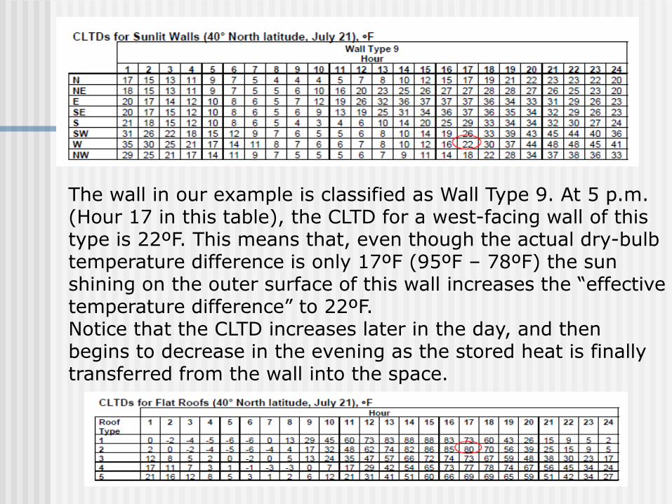
The wall in our example is classified as Wall Type 9. At 5 p.m. (Hour 17 in this table), the CLTD for a west-facing wall of this type is 22ºF. This means that, even though the actual dry-bulb temperature difference is only 17ºF (95ºF – 78ºF) the sun shining on the outer surface of this wall increases the “effective temperature difference” to 22ºF.Notice that the CLTD increases later in the day, and then begins to decrease in the evening as the stored heat is finally transferred from the wall into the space.

Q wall = 0.06 × 380 × 22 = 502 Btu/hr
Q roof = 0.057 × 2,700 × 80 = 12,312 Btu/hr
Conduction through Sunlit Surfaces

U-factors for Windows

Conduction through Windows
Q windows = 0.63 × 160 × 13 = 1,310 Btu/hr
Conduction heat gain through the west-facing windows:U-factor = 0.63 Btu/hr•ft2•°FTotal area of glass = 8 windows x (4 ft x 5 ft) = 160 ft2• CLTDhour=17 = 13ºF

BH = solar gain + conduction
Solar radiation through glass
Q = A × SC × SCL
Q = heat gain by solar radiation through glass, Btu/hr• A = total surface area of the glass, ft2 • SC = shading coefficient of the window, dimensionless• SCL = solar cooling load factor, Btu/hr•ft2

Solar Cooling Load Factor
Direction that the window faces Time of day MonthLatitudeConstruction of interior partition wallsType of floor coveringExistence of internal shading devices
•The solar cooling load (SCL) factor is used to estimate the rate at which solar heat energy radiates directly into the space, heats up the surfaces and furnishings, and is later released to the space as a sensible heat gain. Similar to CLTD, the SCL factor is used to account for the capacity of the space to absorb and store heat.•The shading coefficient (SC) is an expression used to define how much of the radiant solar energy, that strikes the outer surface of the window, is actually transmitted through the window and into the space.

Shading Coefficient

Solar Radiation through Windows
Q windows = 160 × 0.74 × 192 = 22,733 Btu/hr
Solar radiation heat gain through the windows on the west-facing wall:• Total area of glass = 8 windows x (4 ft x 5 ft) = 160 ft2• SC = 0.74• SCL hour=17 = 192 Btu/hr•ft2

Types of Shading Devices
Interior blinds
Installing internal shading devices, such as venetian blinds, curtains, or drapes, can reduce the amount of solar heat energy passing through a window. The effectiveness of these shading devices depends on their ability to reflect the in coming solar radiation back through the window, before it is converted into heat inside the space.

External shading devices, such as overhangs, vertical fins, or awnings, can also reduce the amount of solar heat energy passing through a window. They can be used to reduce the area of the glass surface that is actually impacted by the sun’s rays.
Exterior fins

Internal Heat Gains
While all of these sources contribute sensible heat to the space, people, cooking processes,and some appliances (such as a coffee maker) also contribute latent heat to the space.

Heat Generated by People
people generate more heat than is needed to maintain bodytemperature. This surplus heat is dissipated to the surrounding air in the form of sensible and latent heat. The amount of heat released by the body varies with age, physical size, gender, type of clothing, and level of physical activity.

The equations used to predict the sensible and latent heat gains from people in the space are:QS = number of people x sensible heat gain/person x CLFQL = number of people x latent heat gain/personwhere,• QS = sensible heat gain from people, Btu/hr • QL = latent heat gain from people, Btu/hr• CLF = cooling load factor, dimensionless

CLF Factors for People
For heat gain from people, the value of CLF depends on 1) the construction of the interior partition walls in the space2) the type of floor covering3) the total number of hours that the space is occupied4) the number of hours since the people entered the space.

•The cooling load factor (CLF) is used to account for the capacity of the space to absorb and store heat. Some of the sensible heat generated by people is absorbed and stored by the walls, floor, ceiling, and furnishings of the space, and released at a later time.
•If the space is not maintained at a constant temperature during the 24-hour period, however, theCLF is assumed to equal 1.0. Most air-conditioning systems designed for non-residential buildingseither shut the system off at night or raise the temperature set point to reduce energy use. Thus, it is uncommon to use a CLF other than 1.0 for the cooling load due to people.

Heat Gain from PeopleQ sensible = 18 × 250 × 1.0 = 4,500 Btu/hr
Q latent = 18 × 200 = 3,600 Btu/hr
Internal heat gain from people:• Number of people = 18• Sensible heat gain/person = 250 Btu/hr• Latent heat gain/person = 200 Btu/hr• CLF = 1.0 (because the space temperature set point is increased at night)QS = 18 people x 250 Btu/hr per person x 1.0=4,500 Btu/hrQL = 18 people x 200 Btu/hr per person = 3,600 Btu/hr

Heat Gain from LightingQ = watts × 3.41 × ballast factor × CLF
when estimating the heat gain generated by fluorescent lights, approximately 20% is added to the lighting heat gain to account for the additional heat generated by the ballast.The equation used to estimate the heat gain from lighting is:Q = watts x 3.41 x ballast factor x CLF[Q = watts x ballast factor x CLF]where,• Q = sensible heat gain from lighting, Btu/hr [W]• Watts = total energy input to lights, W• 3.41 = conversion factor from W to Btu/hr • Ballast factor = 1.2 for fluorescent lights, 1.0 for incandescent lights• CLF = cooling load factor, dimensionless
If the lights are left on 24 hours a day, or if the air-conditioning system is shut off or set back at night, the CLF is assumed to be equal to 1.0.

Heat Gain from LightingQ lights = 5,400 × 3.41 × 1.2 × 1.0 = 22,097 Btu/hr
Internal heat gain from lighting:• Amount of lighting in space = 2 W/ft2• Floor area = 45 ft x 60 ft = 2,700 ft2• Total lighting energy = 2 W/ft2 x 2,700 ft2 = 5,400W• Ballast factor = 1.2 (fluorescent lights)• CLF = 1.0 (because the space temperature set point is increased at night)

Heat Generated by Equipment
Additionally, we are told that there are 0.5 W/ft2 of computers and other office equipment in thespace (floor area = 2,700 ft2.Therefore, the internal heat gain from computers and office equipment:Sensible heat gain = 0.5 W/ft2 x 2,700 ft2 x 3.41 Btu/hr/W = 4,604 Btu/hr

InfiltrationAir leaks into or out of a space through doors, windows, and smallcracks in the building envelope. Air leaking into a space is called infiltration. During the cooling season, when air leaks into a conditioned space from outdoors, it can contribute to both the sensible and latent heat gain in the space because the outdoor air is typically warmer and more humid than the indoor air.

Methods of Estimating Infiltration
Air change methodCrack methodEffective leakage-area methodThere are three methods commonly used to estimate infiltration airflow.The air change method is the easiest, but may be the least accurate of these methods. It involves estimating the number of air changes per hour that can be expected in spaces of a certain construction quality. using the equation:Infiltration airflow = (volume of space x air change rate) ÷ 60where,• Infiltration airflow = quantity of air infiltrating into the space, cfm• Volume of space = length x width x height of space,ft3• Air change rate = air changes per hour• 60 = conversion from hours to minutes

•The crack method is a little more complex and is based upon the average quantity of air known to enter through cracks around windows and doors when the wind velocity is constant. •The effective leakage-area method takes wind speed, shielding, and “stack effect” into account, and requires a very detailed calculation.

Heat Gain from Infiltration
Q sensible = 1.1 × airflow × ΔTQ latent = 0.7 × airflow × ΔWQS = sensible heat gain from infiltration, Btu/hr 1.1 = product of density and specific heat,
Btu•min/hr•ft3•ºF Airflow = quantity of air infiltrating the space, cfm ΔT = design outdoor dry-bulb temperature minus the desired indoor dry-bulb temperature, ºF
QL = latent heat gain from infiltration, Btu/hr0.7 = latent heat factor, Btu•min•lb/hr•ft3•gr• Airflow = quantity of air infiltrating the space, cfm• ΔW = design outdoor humidity ratio minus the desired indoor humidity ratio, grains of water/lb of dry air
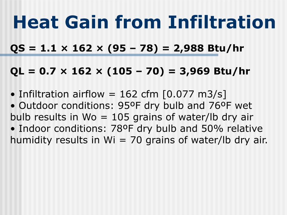
Heat Gain from Infiltration
QS = 1.1 × 162 × (95 – 78) = 2,988 Btu/hr
QL = 0.7 × 162 × (105 – 70) = 3,969 Btu/hr
• Infiltration airflow = 162 cfm [0.077 m3/s]• Outdoor conditions: 95ºF dry bulb and 76ºF wet bulb results in Wo = 105 grains of water/lb dry air• Indoor conditions: 78ºF dry bulb and 50% relative humidity results in Wi = 70 grains of water/lb dry air.

1.1 and 0.7 are not constants, but are derived from properties of air at “standard” conditions.
• Density = 0.075 lb/ft3 • Specific heat = 0.24 Btu/lb•°F • Latent heat of water vapor = 1,076 Btu/lb
0.075 x 0.24 x 60 min/hr = 1.085

Summary of Space Cooling Loads
Ventilation
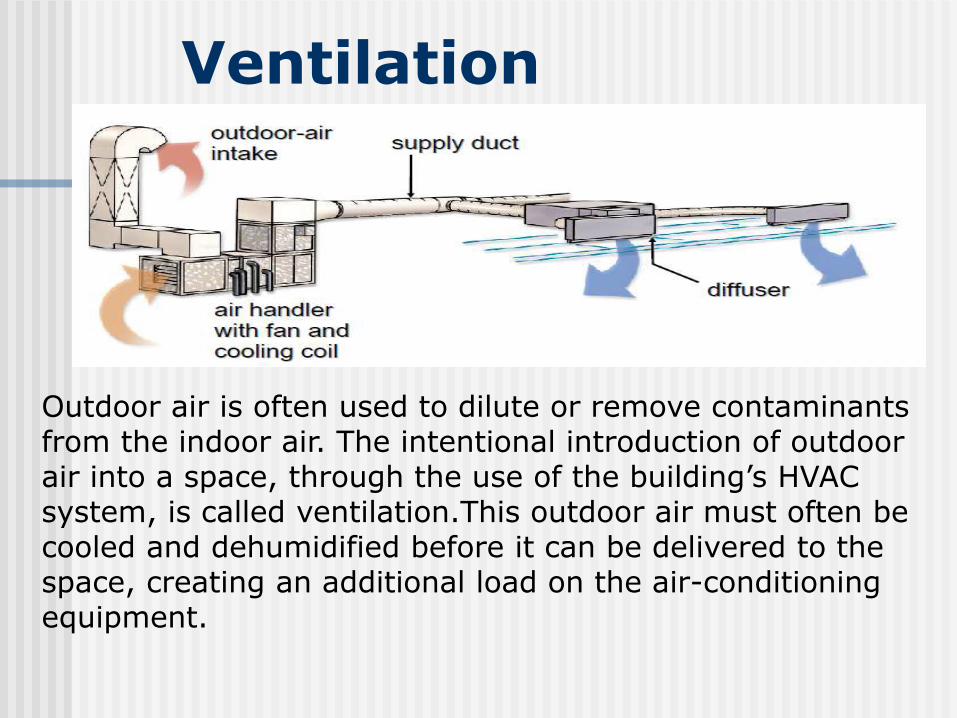
Outdoor air is often used to dilute or remove contaminants from the indoor air. The intentional introduction of outdoor air into a space, through the use of the building’s HVAC system, is called ventilation.This outdoor air must often be cooled and dehumidified before it can be delivered to the space, creating an additional load on the air-conditioningequipment.

It is common to introduce outdoor air through the HVAC system, not only to meet the ventilation needs, but also to maintain a positive pressure (relative to the outdoors) within the building. This positive pressure reduces, or may even eliminate, the infiltration of unconditioned air from outdoors. To pressurize the building, the amount of outdoor air brought in for ventilation must be greater than the amount of air exhausted through central and local exhaust fans.

ventilation airflow =18 people x 20 cfm/person = 360 cfm
Cooling Load Due to Ventilation
QS = 1.1 × 360 × (95 – 78) = 6,640 Btu/hr
QL = 0.7 × 360 × (105 – 70) = 8,820 Btu/hr
Outdoor Air Requirements

System Heat GainsThere may be others sources of heat gain within the HVAC system. One example is the heat generated by fans. When the supply fan, driven by an electric motor, is located in the conditioned airstream, it adds heat to the air. Heat gain from a fan is associated with three energy conversion losses.
1.Fan motor heat gain = power input to motor × (1 – motor efficiency)2. Fan blade heat gain = power input to fan × (1 – fan efficiency)3. Duct friction heat gain = power input to fan × fan efficiency

Components of Fan Heat
It is important to know where the fan heat gain occurs with respect to the cooling coil. If the fan is located upstream and blows air through the cooling coil, the fan heat causes an increase in the temperature of the air entering the coil. If, however, the fan is located downstream and draws air through the cooling coil, the fan heat causes an increase in the temperature of the air supplied to the space.
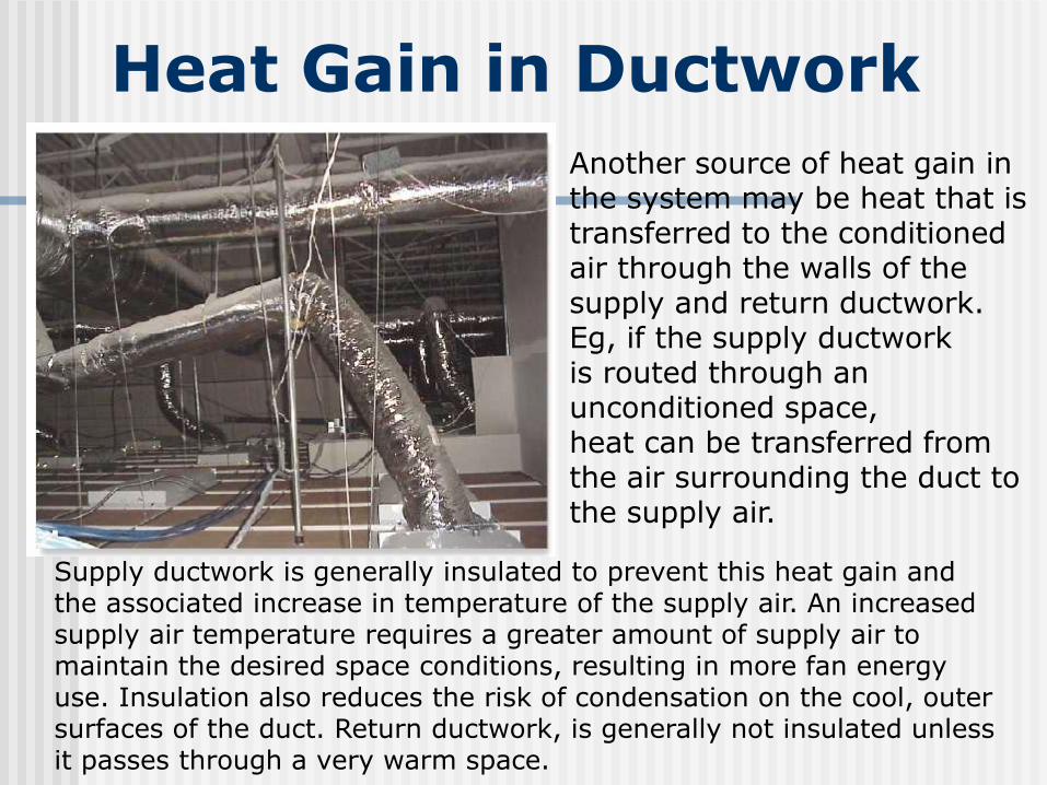
Heat Gain in Ductwork
Another source of heat gain in the system may be heat that istransferred to the conditioned air through the walls of the supply and return ductwork. Eg, if the supply ductworkis routed through an unconditioned space, heat can be transferred from the air surrounding the duct to the supply air.
Supply ductwork is generally insulated to prevent this heat gain and the associated increase in temperature of the supply air. An increased supply air temperature requires a greater amount of supply air to maintain the desired space conditions, resulting in more fan energy use. Insulation also reduces the risk of condensation on the cool, outer surfaces of the duct. Return ductwork, is generally not insulated unless it passes through a very warm space.
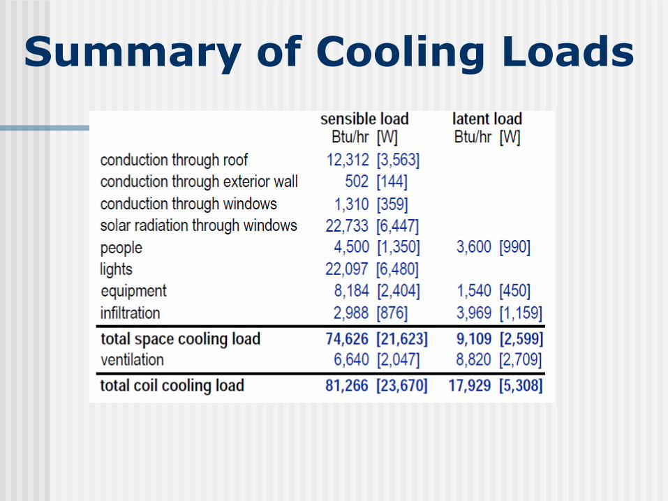
Summary of Cooling Loads

Cooling and Heating Load Estimation-Psychrometric Analysis

Space Load versus Coil Load
Notice that all space loads are also coil loads, but all coil loads are not necessarily also space loads. Ventilation air is conditioned prior to being delivered to the space. Therefore, the ventilation load adds to the total cooling coil load, but does not add to the space cooling load.Additionally,heat gains that occur within the HVAC system, such as fan heat and duct heat gain, are considered coil loads, but not space loads.

Space Sensible and Latent Loads

Sensible Heat Ratio (SHR)
The SHR for our example space is 0.89. That is, 89% of the cooling load for this space is sensible and 11% is latent.

Single-Space Analysis
This analysis assumes that the example space is served by its own dedicated air conditioningsystem, consisting of a cooling coil and supply fan.

Determine Supply Airflow
where,• Sensible heat gain = sensible heat gain in the space, Btu/hr • 1.085 = product of density and specific heat, Btu•min/hr•ft3•ºF • Supply airflow = quantity of air supplied to the space, cfm • Room DB = desired space dry-bulb temperature, ºF • Supply DB = supply air dry-bulb temperature, ºFRemember that 1.085 is not a constant—it is derived from the density and specific heat of the air at actual conditions.

Calculate Entering Coil Conditions
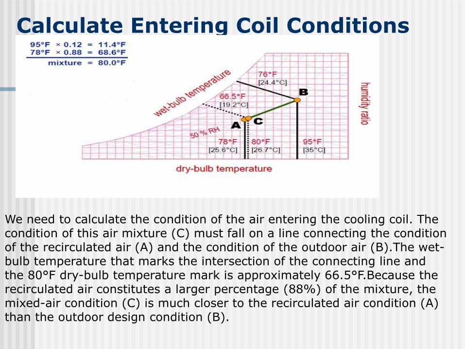
Calculate Entering Coil Conditions
We need to calculate the condition of the air entering the cooling coil. The condition of this air mixture (C) must fall on a line connecting the condition of the recirculated air (A) and the condition of the outdoor air (B).The wet-bulb temperature that marks the intersection of the connecting line and the 80°F dry-bulb temperature mark is approximately 66.5°F.Because therecirculated air constitutes a larger percentage (88%) of the mixture, the mixed-air condition (C) is much closer to the recirculated air condition (A) than the outdoor design condition (B).

Determine Supply Air Temperature
Now to determine the supply-air condition (dry-bulb and wet-bulb temperatures) necessary to absorb the sensible and latent heat in the space.
A sensible-heat-ratio line is drawn by connecting the 0.89 value on the SHR scale with the index point. Since the index point is the same as the desired space condition for this example (A), this line is extended until it intersects the saturation curve. If the desired space condition was different, a line would be drawn parallel to the 0.89 SHR line through the space condition.Using the curvature of the nearest two coil curves as a guide, draw a curve from the mixed air condition (C) until it intersects the SHR line.This point of intersection (D) represents the supply-air condition that will offset the space sensible and latent heat gains in the correct proportions required to maintain the desired space condition. Here, this supply-air condition is 59°F dry bulb, 57.4°F wet bulb.

Recalculate Supply Airflow

Total Cooling Load on Coil

Multiple-Space Analysis
If each space is conditioned by a separate system, thenthe fan and coil would be sized to handle the maximum load for the particular space. If,however, a single system is used to condition several spaces in a building, the method used to size the fan and coil depends on whether the system is a constant-volume (CV) or variable-air-volume (VAV) system.If the supply fan delivers a constant volume of air, the fan must be sized by summing the peak sensible loads for each of the spaces it serves.If, however, it is a VAV system and the fan delivers a varying amount of air to the system, the fan is sized based on the one-time, worst-case airflow requirement of all of the spaces it serves.

Room 101 (Faces West)
Because room 101 has several west-facing windows, the peak (highest) space sensible load occurs in the late afternoon when the sun is shining directly through the windows.

Room 102 (Faces East)
Because room 102 has several east-facing windows, the peak space cooling load occurs in the morning when the rising sun shines directly through the windows.
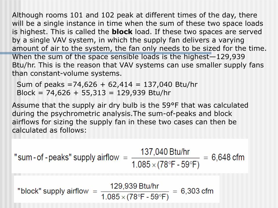
Sum of peaks =74,626 + 62,414 = 137,040 Btu/hrBlock = 74,626 + 55,313 = 129,939 Btu/hr
Assume that the supply air dry bulb is the 59°F that was calculated during the psychrometric analysis.The sum-of-peaks and block airflows for sizing the supply fan in these two cases can then be calculated as follows:
Although rooms 101 and 102 peak at different times of the day, there will be a single instance in time when the sum of these two space loads is highest. This is called the block load. If these two spaces are served by a single VAV system, in which the supply fan delivers a varying amount of air to the system, the fan only needs to be sized for the time. When the sum of the space sensible loads is the highest—129,939 Btu/hr. This is the reason that VAV systems can use smaller supply fans than constant-volume systems.

“Block” Cooling Load
12000 Btu/hr = 1 TRThen 179,077/12000 =14.92 TR

Computerized Load AnalysisTime SavingsDetermining time of peakand block loadsChanges to building design Space usage Building orientation Construction materials ZoningPerforming “what if?”
analyses

Space versus Plenum Loads
roof
lights
plenum
exteriorwall
return air
ceiling
Heat absorbed by Return Air

Space versus Plenum Loads
While some of this heat is absorbed by the return air, 3,620 Btu/hr is transferred through the ceiling into the space. This heat transfer between the plenum and the space does affect the space sensible load, but it does not affect the coil load. This is because any heat that is not transferred to the space is absorbed by the return air and must be eventually removed by the cooling coil.

Ducted Return

People

Equipment - Office

Equipment-Restaurant

Heat Gain in Ductwork
•If insulated –Add 1-3% depending of the extent of the duct work
•Not insulated –Add 10 – 15% depending on extent of duct work or climate (best to calculate gain by conduction)
BH = U A T
Duct leakage – If outside of conditioned space add 5%

Review
Thermal comfort depends upon creating an environment of dry-bulb temperature, humidity and air motion that is appropriate for the activity level of the people in the space. This environment allows the body’s rate of heat generation to balance with the body’s rate of heat loss. ASHRAE has prescribed a “comfort zone” that can be used as the basis for HVAC system design.
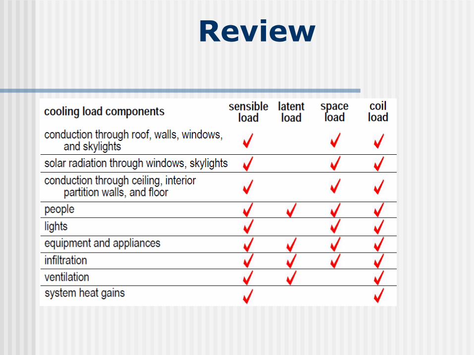
Review

Basic components of Air
conditioner

The parts we find in a airconditioning system are
• compressor
• condeser
• expantion valve
• evaporator
• accumulator
• drier
• sight glass
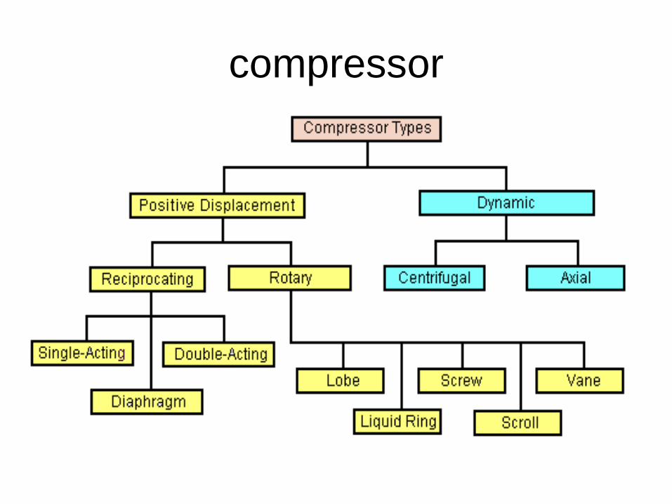
compressor

positive displacement compressors
This reduces the volume of a constant
amount of gas
This could be divided further
1. reciprocating compressors
2. rotary compressors
Reciprocating compressors
A reciprocating compressor or piston
compressor is a positive-displacement
compressor that uses pistons driven by a
crankshaft to deliver gases at high
pressure.

• Reciprocating compressor are used for
large duty cycle work
• They are basically energy hungry
• They have a longer life time

Advatages
• Simple design, easy to install
• Lower initial cost
• Large range of horsepower
• Special machines can reach extremely high pressure
• Two stages models offer the highest efficiency

Disadvatages
• Higher maintenance cost
• Many moving parts
• Potential for vibration problems
• Foundation may be required depending on
size
• Many are not designed to run at full
capacity

Reciprocating compressor could be further
divide intoa) single acting compressor
b) Double acting compressor
c) dighpram compressor

• single and double acting compressors
were once the most commonly used
compressors
• These compressors have been replaced
by rotary screw compressors
• The reciprocating compressors are smaller
and requires lesser foundation

• it is lesser efficient since it uses lesser
horse power
• It produces more noise in comparison with
a screw compressor
• It has a longer life time

single acting compressors
It is a compressor that has one discharge per
revolution of crankshaft.

piston rings

Piston rings provide a seal that prevents or minimizes
leakage through piston and liner. Metal piston rings are
made either in one piece, with a gap or in several
segments. Gaps in the rings allow them to move out or
expand as the compressor reaches operating
temperature.

crankshaft

• The crankshaft is built in a single piece.
On the inside of the shaft are holes for
passage and distribution of lube oil.
• Lubricants reduce friction and therefore
wear between moving compressor parts.
Lubricant also serves as a coolant.

piston
• For low speed compressors (upto 330 rpm) and
medium speed compressors (330-600 rpm),
pistons are usually made of cast iron.
• Upto 7” diameter cast iron pistons are made of
solids. Those of more than 7” diameters are
usually hollow (to reduce cost).
• Carbon pistons are sometimes used for
compressing oxygen and other gases that must
be kept free of lubricant.

cylinder and liner
• Piston reciprocates inside a cylinder. To provide for
reduced reconditioning cost, the cylinder may be fitted
with a liner or sleeve. A cylinder or liner usually wears at
the points where the piston rings rub against it. Because
of the weight of the piston, wear is usually greater at the
bottom of a horizontal cylinder. A cylinder liner is usually
counter bored near the ends of the outer ring travel i.e.
counter bores are made just ahead of the points where
the end piston rings stop and reverse direction.
Shoulders may form in the liner where the ring’s travel
stops unless counter bores are provided.


piston rod packing

• Piston rod packing ensures sealing of the compressed
gas. The piston rod packing consists of series of cups
each containing several seal rings side by side. The
rings are built of three sectors, held together by a spring
installed in the groove running around the outside of the
ring.
• The entire set of cups is held in place by stud bolts.
Inside channels are there for cooling, gas recovery and
lubrication of the piston rod packing.

piston rods and piston

• Generally, the piston rod is fastened to the piston by
means of special nut that is prevented from unscrewing.
The surface of the rod has suitable degree of finish
designed to minimize wear on the sealing areas as much
as possible. The piston is provided with grooves for
piston rings and rider rings.
• The function of rider rings, is to support or guide the
piston and rod assembly and prevent contact between
the piston and the cylinder (risk of seizure).

crank case
• Crank case supports the crankshaft. All
bearing supports are bored under setup
condition to ensure perfect alignment.
Crankcase is provided with easy
removable covers on the top for inspection
and maintenance. The bottom of the
crankcase serves as the oil reservoir.


connecting rod
• The connecting rod has two bearings. The
big end bearing is built in two halves. It is
made of metal with inner coating of
antifriction metal. The connecting rod
small end bearing is build of steel, with
inner coating of antifriction metal. A hole
runs through the connecting rod for it’s
entire length, to allow passage of oil from
the big end to the small end bush.


Cross Head
Crosshead fastens piston rod to the connecting rod
It permits to slide back and fort within the cross head slide
it has channels fro distribution of oil

Lubrication system

Double acting compressors

• This type of compressor operates in exactly the same way as the single acting with respect to its action. The difference is, that the cylinder has inlet and outlet ports at each end of the cylinder As the piston moves forward, liquid is being drawn into the cylinder at the back end while, at the front end, liquid is being discharged. When the piston direction is reversed, the sequence is reversed.

Dighpram compressor

• Dighpram compressor is a kind of
displacement compressor driven by
displacement motor.
• The particularity of dighpram compressors
is that there are two chambers in a
cylinder body
• A hydraulic oil chamber and a gas
chamber
• when the machine is started the
electromotor drives the crankshaft making
rotational moments
• The crankshaft is connected with a piston
by a connecting rod which can transform
the rotational moment of the crankshaft
into reciprocating moment of the piston

• when the piston is pulled to the down end
the hydraulic oil will flow back to the
cylinder
• The pressure difference will mske the
dighprams have a downward elastic
deformation.
• The volume of the gas chamber will be
enlarged

• The gas inlet valve will open automatically
• In this way the gas is sucked in
• when the con-rod pushes the piston to the
top end the piston will further push the
hydraulic oil to make the dighpram have a
upper elastic deformation

• The voulume of the gas chamber reduces
and the gas is compressed
• The gas discharge valve will be opened
automatically when the gas pressure
reaches a certain value
• As a result of dighprams periodic elastic
derformation ,the gas is sucked
compressed and discharged periodically.

Rotary compressors
Rotary compressors are those
compressors which use rotors instead of
piston to compress gas.
The different types of rotary compressors
are screw ,vane ,scroll ,lobe and liquid ring
compressors

• Rotory compressors are energy effictient
• Rotary compressors have a lower duty
cycle
• They have a shorter life span in
comparison with a reciprocating
compressor
Advantages
• Simple design
• Low to medium initial and maintenance cost
• Two-stages design provide good efficiencies
• Easy to install
• Few moving parts

Disadvatages
• High rotational speed
• Shorter life expectancy than any other
designs
• Single-stage designs have lower efficiency
• Difficulty with dirty environment

screw compressors

• one of the most appealing factor of this
compressor is that its excellent return on
investment.
• Low initial installation and maintenance
cost
• it requires smaller floor space and it is
lesser noisy when compared with a
reciprtocating compressor

Rotary screw compressors use two meshing
helical screws, known as rotors, to compress the
gas. In a dry running rotary screw compressor,
timing gears ensure that the male and female
rotors maintain precise alignment. In an oil-
flooded rotary screw compressor, lubricating oil
bridges the space between the rotors

• A typical oil flooded twin screw
compressor consists of male and female
rotors mounted on bearings to fix their
position in a rotor housing which holds the
rotors inclosely toleranced intersecting
cylindrical bores
The driving device is generally connected to the male rotor with the male driving the female through an oil film
Some designs connect the drive to the female rotor in order to produce higher rotor speeds thus increasing displacement. However, this increasesloading on the rotors in the area of torque transfer and can reduce rotor life.

One screw has a right-handed thread, and the
other screw has a left-handed thread and they
rotate in opposite directions.The screws rotate in
closely fitting cylinders that have overlapping
bores. All clearances are small, but there is no
actual contact between the two screws or
between the screws and the cylinder walls.

Suction gas is drawn into the compressor
to fill the void where the male rotor rotates
out of the female flute on the suction end
of the compressor. Suction charge fills the
entire volume of each screw thread as the
unmeshing thread proceeds down the
length of the rotor.

Gas is compressed by pure rotary motion
of the two intermeshing helical rotors. Gas
travels around theoutside of the rotors,
starting at the top and traveling to the
bottom while it is transferredaxially from
the suction end to the discharge end of the
rotor area.

vane compressor
When a gas is compressed in the compressor, its temperature is increased considerably. To prevent spontaneous combustion of the lubricant, the compressor is equipped with water cooling (with a pipe for water supply) or air cooling. In this way, the air compression process will approximate an isothermal process (with constant temperature), which is theoretically most advantageous.


• Rotary compressors have one or more
rotors, which may be of various designs.
Considerable use is made of rotary
(sliding-vane) compressors (Figure 2),
which have a rotor with slots into which the
vanes fit freely. The rotor is located
eccentrically in the cylinder of the casing.
Upon clockwise rotation of the rotor,

spaces bounded by the vanes, as well as the surfaces of the rotor and cylinder casing, will increase in the left half of the compressor, thus causing the inlet of gas through the aperture. In the right half of the compressor the volume of the spaces decreases and the gas within them is compressed and then delivered from the compressor to the cooler or directly into the pressure piping. The casing of rotary compressors is cooled by water, which is supplied and discharged through pipes

scroll compressor

This compressor is a wonderful invention,
since it has only 1 moving part. The
compressor exists of two spiral elements.
One moves in eccentric circles and the other
one is stationary.

• What happens? Air gets trapped between
the two spirals at the suction side and get
transported to the center of the spiral. This
way the air is compressed. It takes about
2.5 turns for the air to reach the center
exhaust pipe.


Lobe compressors
Rotary Lobe type Air Compressor has two
mating lobe-type rotors mounted in a case. The
lobes are gear driven at close clearance, but
without metal-to-metal contact. The suction to the
unit is located where the cavity made by the lobes
is largest.

As the lobes rotate, the cavity size is
reduced, causingcompression of the vapor
within. The compression continues until the
discharge port is reached, at which point the
vapor exits the compressor at a higher
pressure.


Liquid ring compressor

•The liquid ring pump compresses gas by rotating a vaned impeller located eccentrically within a cylindrical casing. Liquid (usually water) is fed into the pump and, by centrifugal acceleration, forms a moving cylindrical ring against the inside of the casing. This liquid ring creates a series of seals in the space between the impeller vanes, which form compression chambers. The eccentricity between the impeller's axis of rotation and the casing geometric axis results in a cyclic variation of the volume enclosed by the vanes and the ring.

Gas, often air, is drawn into the pump via an inlet port in the end of the casing. The gas is trapped in the compression chambers formed by the impeller vanes and the liquid ring. The reduction in volume caused by the impeller rotation compresses the gas, which reports to the discharge port in the end of the casing.


Dynamic compressors
Adding more amount of gas in a constant
amount of volume. Common
types of dynamic compressors include
• centrifugal compressors
• axial compressors

• The dynamic compressor is characterized
by rotating impeller to add velocity and
pressure to fluid. Compare to positive
displacement type compressor, dynamic
compressor are much smaller in size and
produce much less vibration.

• It is widely used in chemical and
petroleum refinery industry for specifies
services. They are also used in other
industries such as the iron and steel
industry, pipeline booster, and on offshore
platforms

Axial compressors

Axial flow compressors are used mainly as
compressors for gas turbines. They are
used in the steel industry as blast furnace
blowers and in the chemical industry for
large nitric acid plantsThe efficiency in an
axial flow compressor is higher than the
centrifugal compressor.

Advatages
• High peak efficiency
• Small frontal area for given airflow
• Increased pressure rise due to increased
number of stages with negligible losses

Disadvatages
• Good efficiency over narrow rotational
speed range
• Difficulty of manufacture and high cost.
• Relatively high weight
• High starting power requirements

Axial-flow compressors are dynamic rotating compressors
that use arrays of fan-like airfoils to progressively compress
the working fluid. They are used where there is a
requirement for a high flow rate or a compact design.
The arrays of airfoils are set in rows, usually as pairs: one
rotating and one stationary. The rotating airfoils, also
known as blades or rotors, accelerate the fluid.

• The stationary airfoils, also known as
stators or vanes, decelerate and redirect
the flow direction of the fluid, preparing it
for the rotor blades of the next stage.Axial
compressors are almost always multi-
staged, with the cross-sectional area of
the gas passage diminishing along the
compressor to maintain a high pressure.

Applications
• Axial compressors can have high efficiencies; around 90% polytropic at their design conditions. However, they are relatively expensive, requiring a large number of components, tight tolerances and high quality materials. Axial-flow compressors can be found in medium to large gas turbine engines, in natural gas pumping stations, and within certain chemical plants.

centrifugal compressors

Advantages
• High efficiency approaching two stages
reciprocating compressor
• Can reach pressure up to 1200 psi
• Designed to give lubricant free air
• Does not require special foundations

Disadvantages
High initial cost
Complicated monitoring and control systems
Limited capacity control modulation,
requiring unloading for reduced capacities
High rotational speed require special
bearings and sophisticated vibration and
clearance monitoring
Specialized maintenance considerations

Centrifugal compressors use the rotating action
of an impeller wheel to exert centrifugal force on
refrigerant inside a round chamber (volute). A
diffuser (divergent duct) section converts the
velocity energy to pressure energy.
Unlike other designs, centrifugal compressors do
not operate on the positive displacement
principle, but have fixed volume chambers. They
are well suited to compressing large volumes of
refrigerant to relatively low pressures.

• The compressive force generated by an impeller wheel is small, so systems that use centrifugal compressors usually employ two or more stages (impellers wheels) in series to generate high compressive forces. Centrifugal compressors are desirable for their simple design, few moving parts, and energy efficiency when operating multiple stages.

applications
• Many large snowmaking operations (like
ski resorts) use this type of compressor.
They are also used in internal combustion
engines as superchargers and
turbochargers. Centrifugal compressors
are used in small gas turbine engines or
as the final compression stage of medium
sized gas turbines.

Expansion valve
There are basically two types of expansion
valves
• Internally equalised valve
• Externally equalised valve

constant pressure expansion valve

The constructional details of the constant pressure
expansion valve are shown in the figure above. It
comprises of the metallic body inside which is the metallic
diaphragm or bellow. On the upper side of the diaphragm is
the spring which is under pressure and its pressure is
controlled by the adjusting screw.
Below the diaphragm there is thin plate or seat that has the
small opening. The opening in the seat is controlled by the
needle or stem connected to the diaphragm.

As the diaphragm moves down the needle
also moves down thus opening the valve.
The the seat and the needle form the orifice
for the constant pressure valve.
There are also two opening in the valve.
From one side the refrigerant from the condenser
enters the expansion valve and from the other side
the refrigerant leaves the valve to enter the
evaporator.
The spring above the diaphragm is under compression thus
the spring pressure along with the atmospheric pressure
acts on the diaphragm. Due to the pressure the diaphragm
tends to move down due to which the needle also tends to
move down away from the seat leading to the opening of
the valve.
Below the diaphragm there is refrigerant at the evaporator
pressure thus the evaporator pressure tends to move the
diaphragm in the upward direction. Due to this the needle
tends to move in the upward direction towards the seat to
close the valve.

Thus the spring pressure and the evaporator
pressure act against each other and
whichever is greater would determine the
position of the needle and the opening of the
orifice of the valve. In the normal running
condition of the plant the valve maintains
equilibrium between the evaporator pressure
and the spring pressure and maintains
certain opening of the valve to allow the flow
of refrigerant through it.

The tension of the spring can be adjusted as
per the requirements by the adjusting screw.
The constant pressure expansion valve
maintains the pressure inside the evaporator
constant and automatically as per the setting
of the spring pressure. This means that the
evaporator pressure can be varied by
changing the position of the spring.

Internally equalised expansion
valve

Opposed to this opening force on the underneath side of the diaphragm and acting in the closing direction are two forces: (1) the force exerted by the evaporator pressure and (2) that exerted by the superheat spring. In the first condition, the valve will assume a stable control position when these three Forces are in balance (that is, when P1 = P2 + P3).

In the next step, the temperature of the
refrigerant gas at the evaporator outlet
(remote bulb location) increases above the
saturation temperature corresponding to
the evaporator pressure as it becomes
superheated. The pressure thus
generated in the remote bulb, due to this
higher temperature, Increases above the
combined pressures of the evaporator
pressure and the superheat spring (P1
greater than P2 + P3) And causes the
valve pin to move in an opening direction.

Conversely, as the temperature of the
refrigerant gas leaving the evaporator
decreases, the pressure in the remote
bulb and Power assembly also decreases
and the combine evaporator and Spring
pressure cause the valve pin to move in a
closing Direction (P1 less than P2 + P3).

Externally equalised expansion
valve
• In order to compensate for an excessive
pressure drop through an evaporator, the
thermal expansion valve must be of the
external equalizer type, with the equalizer
line connected either into the evaporator at
a point beyond the greatest pressure drop
or into the suction line at a point on the
compressor side of the remote bulb
location.


Drier

• The functions of drier in brief are (i) to
receive and store liquid refrigerant for the
evaporator,
• (ii) to filter out any dirt from the refrigerant,
(Hi) to absorb mdisture if present in the
refrigerant, and (iv) to trap any refrigerant
vapour that did not condense in the
condenser.

Accumulator

• Some air conditioners use an accumulator to prevent liquid refrigerant from entering the compressor. The accumulator also serves as a tank to store excess liquid refrigerant and contains a desiccant. The desiccant in the accumulators serves the same function as in receives-drier.

• Liquid refrigerant is collected at the bottom
of the tank. Refrigerant vapour remains at
the top of the tank, and is passed to the
compressor through the pickup tube. At
the bottom of the tank, the pickup tube
contains a small hole or orifice,

• which allows a very small amount of
trapped oil or liquid refrigerant to return to
the compressor, without damaging the
compressor. The accumulator cannot be
serviced unlike the receiver-drier, and
hence if found defective, has to be
replaced.

Types of refrigeration evaporators
• Bare Tube Evaporators
The bare tube evaporators are made up of copper tubing or steel pipes. The copper tubing is used for small evaporators where the refrigerant other than ammonia is used, while the steel pipes are used with the large evaporators where ammonia is used as the refrigerant. The bare tube evaporator comprises of several turns of the tubing, though most commonly flat zigzag and oval trombone are the most common shapes.

• The bare tube evaporators are usually
used for liquid chilling. In the blast cooling
and the freezing operations the
atmospheric air flows over the bare tube
evaporator and the chilled air leaving it
used for the cooling purposes. The bare
tube evaporators are used in very few
applications, however the bare tube
evaporators fitted with the fins, called as
finned evaporators are used


Plate Type of Evaporators

• In the plate type of evaporators the coil usually made up
of copper or aluminum is embedded in the plate so as so
to form a flat looking surface. Externally the plate type of
evaporator looks like a single plate, but inside it there are
several turns of the metal tubing through which the
refrigerant flows. The advantage of the plate type of
evaporators is that they are more rigid as the external
plate provides lots of safety. The external plate also
helps increasing the heat transfer from the metal tubing
to the substance to be chilled. Further, the plate type of
evaporators are easy to clean and can be manufactured
cheaply.

Finned Evaporators

• The finned evaporators are the bare tube type of evaporators covered with the fins. When the fluid (air or water) to be chilled flows over the bare tube evaporator lots of cooling effect from the refrigerant goes wasted since there is less surface for the transfer of heat from the fluid to the refrigerant. The fluid tends to move between the open spaces of the tubing and does not come in contact with the surface of the coil, thus the bare tube evaporators are less effective. The fins on the external surface of the bare tube evaporators increases the contact surface of the of the metallic tubing with the fluid and increase the heat transfer rate, thus the finned evaporators are more effective than the bare tube evaporators.

Shell and Tube types of
Evaporators
• The shell and tube types of evaporators are
used in the large refrigeration and central air
conditioning systems. The evaporators in these
systems are commonly known as the chillers.
The chillers comprise of large number of the
tubes that are inserted inside the drum or the
shell. Depending on the direction of the flow of
the refrigerant in the shell and tube type of
chillers, they are classified into two types: dry
expansion type and flooded type of chillers.

• In dry expansion chillers the refrigerant flows along the tube side and the fluid to be chilled flows along the shell side. The flow of the refrigerant to these chillers is controlled by the expansion valve. In case of the flooded type of evaporators the refrigerant flows along the shell side and fluid to be chilled flows along the tube. In these chillers the level of the refrigerant is kept constant by the float valve that acts as the expansion valve also.
Air-Cooled Condensers
• An air-cooled condenser consists of a coil of ample surface that air is blown by a fan or induced by natural draft. This type of condenser is universally used in small capacity refrigerating units. Mostly designed for residential or small office air conditioners.
• Air-chilled condensers should be kept from free from dirt, lint and other foreign materials because they tend to reduce the airflow around the tubes and fins if they are allowed to accumulate just like evaporators.

Combined Air- and Water-cooled
Condensers• This type of condenser is also know as an
evaporative condenser and consists of a coil cooled by water sprayed from above and then cold air enters from the bottom and is blown across the coils. As water evaporates from the coil it creates a cooling effect that condenses the refrigerant within the coil. The refrigerant gas in the coil is hot which changed to the liquid state by combining the sprayed water and the large column of moving air supplied by the fan. The water that does not evaporate is recirculated by means of a pump.

Water-Cooled Condensers
• A water-cooled condenser is similar to a steam surface condenser in that cooling is accomplished by water alone that circulates through tubes or coils enclosed in a shell. IN a water-cooled condenser the refrigerant circulates through the annular space between the tubes or coils. Because of its construction, a water-cooled condenser is also referred to as a double-pipe condenser

Heating, Ventilating, Air-Conditioning
&
Refrigeration Technology

CONDITIONING EQUIPMENT
• Air has to be conditioned in most cases for us to be comfortable
• Equipment includes cooling coil, heating device, device to add humidity, and device to clean air
• Forced air systems use the same room air over and over again
• Fresh air enters the structure by infiltration or by mechanical means
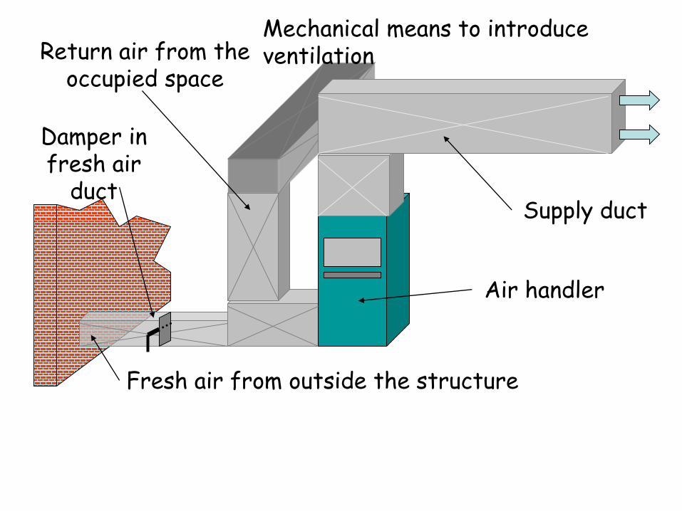
Supply duct
Return air from the occupied space
Air handler
Fresh air from outside the structure
Damper in fresh air
duct
Mechanical means to introduce ventilation

CORRECT AIR QUANTITY
• The forced air system delivers the correct quantity of conditioned air to the occupied space
• Different spaces require different air quantities
• Same structure may have several different cooling requirements

Living Room 9,000 btu (cooling)
18,000 btu (heating) 300 cfm
100 cfm
100 cfm
200 cfm
100 cfm
200 cfm
50 cfm
100 cfm
50 cfm
THE FORCED-AIR SYSTEM
• Components that make up the forced-air system – The blower– Air supply system– Return air system – Grilles and registers
• Occupants should not be aware if the system is on or off

Supply duct
Return air from the occupied space
Air handler (blower)
Supply registers

THE BLOWER
• Provides the pressure difference to force the air into the duct system, through the grilles and registers, and into the room
• Typically 400 cfm of air must be moved per minute per ton of air conditioning
• Pressure in the ductwork is measured in inches of water column (in. W.C)
• Air pressure in the ductwork is measured with a water manometer

SYSTEM AIR PRESSURES
• Duct system is pressurized by two pressures – Static pressure – air pressure in the duct
– Velocity pressure – pressure generated by the velocity and weight of the air
– Combined, these pressures are called
– “Total pressure “
• Static pressure plus velocity pressure equals total pressure

Static pressure
Duct
Airflow
Probe located on
the surface of the duct

Total pressure
Probe located in the duct, facing
into the direction of
airflow

Velocity pressure
Velocity pressure = Total pressure – Static pressure
Total pressure
Static pressure

AIR-MEASURING INSTRUMENTS FOR DUCT SYSTEMS
• Velometer – Measures actual air velocity (how fast the air is actually moving in the duct)
• Air volume in cfm can be calculated by multiplying the air velocity by the cross-sectional area of the duct in square feet
• Pitot tube – Used with special manometers for checking duct pressure

PROPELLER FAN
• Used in exhaust fan and condenser fan application
• Will handle large volumes of air at low pressure differentials
• Set into a housing called a venturi• The venturi forces airflow in a straight
line from one side of the fan to the other • Makes noise and is used where noise is not
a factor

Propeller fan
Venturi

SQUIRREL CAGE OR CENTRIFUGAL FAN
• Desirable for ductwork
• Builds more pressure from the inlet to the outlet
• Has a forward curved blade and a cutoff to shear the air spinning around the fan wheel
• Very quiet when properly applied
• Can be used in very large high-pressure systems

Centrifugal BlowerEnd View of Squirrel Cage
Blower Wheel

CENTRIFUGAL BLOWER HOUSING

TYPES OF FAN DRIVES
• Belt-drive blowers have two bearings on the fan shaft and two bearing on the motor
• Motor pulleys and fan motor pulleys can be adjusted to change fan speeds
• Direct-drive motors use no pulleys or belts• Direct-drive motors can be multi-speed
motors • Speeds can be changed by changing motor
wire leads

BLOWER
MOTOR
BOTH THE DRIVE AND DRIVEN
PULLEYS MUST BE PERFECTLY ALIGNED
Belt-driven Assembly

DIRECT DRIVE MOTOR ASSEMBLY
THE MOTOR AND THE BLOWER TURN AT THE SAME SPEED

THE SUPPLY DUCT SYSTEM
• Distributes air to the terminal units, registers, or diffusers in the conditioned space
• Duct systems– Plenum system– Extended plenum system– Reducing plenum system– Perimeter loop

THE PLENUM SYSTEM
• Suited for a job where the room outlets are all close to the unit
• Supply diffusers are normally located on the inside walls
• Work better on fossil-fuel systems
• Fossil-fuel supply air temperatures could easily reach 130°F

Plenum system
Return duct
Supply plenumBranch ducts
THE EXTENDED PLENUM SYSTEM
• Can be applied to a long structure
• This system takes the plenum closer to the farthest point
• Called the trunk duct system
• Ducts called branches complete the connection to the terminal units

Living Room 9,000 btu (cooling)
18,000 btu (heating) 300 cfm
100 cfm
100 cfm
200 cfm
100 cfm
200 cfm
50 cfm
100 cfm
50 cfm
THE EXTENDED PLENUM SYSTEM

THE REDUCING PLENUM SYSTEM
• Reduces the trunk duct size as branch ducts are added
• Has the advantage of saving material and keeping the same pressure from one end of the duct system to the other

Living Room 9,000 btu (cooling)
18,000 btu (heating) 300 cfm
100 cfm
100 cfm
200 cfm
100 cfm
200 cfm
50 cfm
100 cfm
50 cfm
THE REDUCING EXTENDED PLENUM SYSTEM

THE PERIMETER LOOP SYSTEM
• Well suited for installation in a concrete floor in a colder climate
• Warm air is in the whole loop when the furnace fan is running
• Keeps the slab at a more even temperature
• Provides the same pressure to all outlets

Living Room 9,000 btu (cooling)
18,000 btu (heating) 300 cfm
100 cfm
100 cfm
200 cfm
100 cfm
200 cfm
50 cfm
100 cfm
50 cfm
THE PERIMETER LOOP SYSTEM

DUCT MATERIALS
• Ductwork must meet local codes • For years, galvanized sheet metal was
used exclusively • Other ductwork materials
– Aluminum– Fiberglass ductboard– Spiral metal duct– Flexible duct

GALVANIZED STEEL DUCT
• Gauge is the measurement of the thickness of galvanized steel duct
• The gauge size means how many pieces of that material would need to be stacked together to make a one-inch stack
• Metal duct can be round, square, or rectangular

JOINING SECTIONS OF GALVANIZED DUCT WITH SLIPS AND DRIVES
SlipDrive cleat
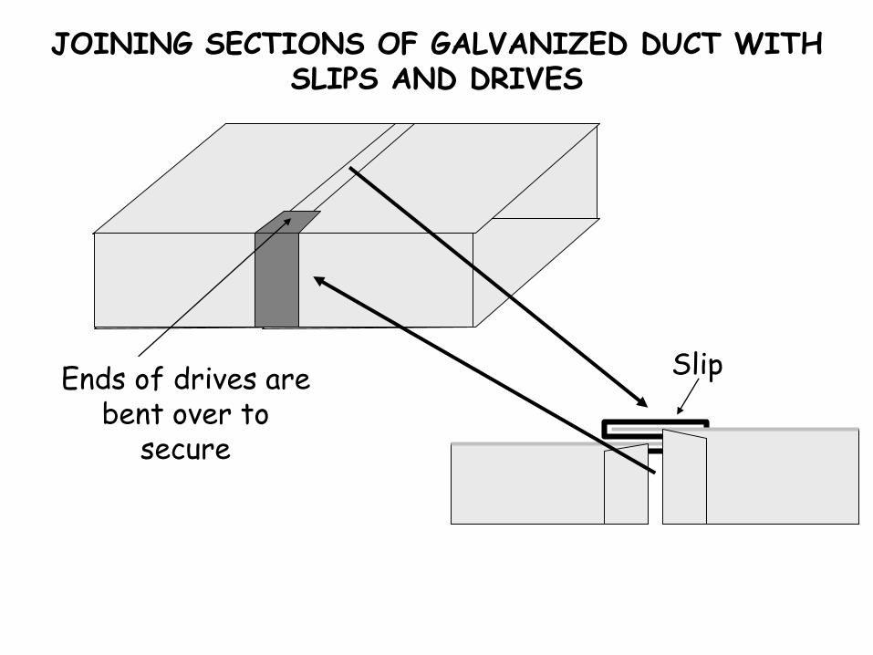
JOINING SECTIONS OF GALVANIZED DUCT WITH SLIPS AND DRIVES
Ends of drives are bent over to
secure
Slip

FIBERGLASS DUCT
• Styles: Flat sheet or round prefabricated cut
• Duct is normally 1 in. thick with aluminum foil backing
• Special knives are used to make special cuts to turn duct board into ductwork
• All duct seams should be stapled and taped

SPIRAL METAL DUCT
• Used more on large systems• Comes in rolls of flat narrow
metal• Runs can be made at the job site• Can be located within the
occupied space for a more contemporary look
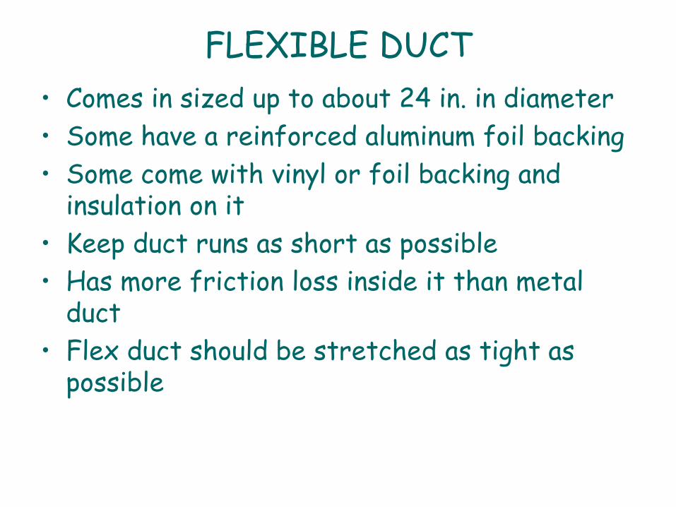
FLEXIBLE DUCT
• Comes in sized up to about 24 in. in diameter
• Some have a reinforced aluminum foil backing
• Some come with vinyl or foil backing and insulation on it
• Keep duct runs as short as possible
• Has more friction loss inside it than metal duct
• Flex duct should be stretched as tight as possible

Floor Register
Flexible Duct
Damper Supply
Return

COMBINATION DUCT SYSTEMS
• Metal trunk lines with round branch ducts
• Metal trunk lines with flexible branch ducts
• Ductboard trunk lines with round metal branch ducts
• Ductboard trunk lines with flexible branch ducts
• Round metal duct with round metal branch ducts
• Round metal trunk lines with flexible branch ducts

DUCT AIR MOVEMENT
• Branch ducts are fastened to the main trunk by a takeoff-fitting
• The takeoff encourages the air moving the duct to enter the takeoff to the branch duct
• Air moving in the duct has inertia, meaning it wants to move in a straight line
• Using turning vanes will improve the air-flow around corners

Main supply duct
Takeoff fitting
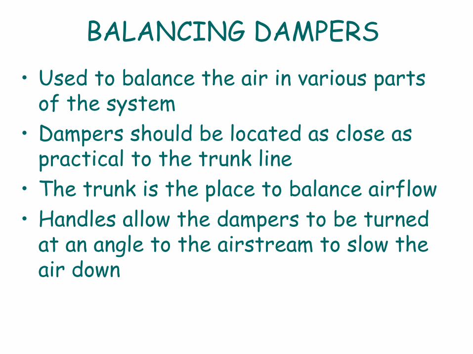
BALANCING DAMPERS
• Used to balance the air in various parts of the system
• Dampers should be located as close as practical to the trunk line
• The trunk is the place to balance airflow
• Handles allow the dampers to be turned at an angle to the airstream to slow the air down

Branch ductBalancing damper in the closed position
Damper in the open position

DUCT INSULATION
• A 15°F temperature difference from the inside of the duct to the outside of the duct is considered the maximum difference allowed before insulation is necessary
• Metal duct can be insulated on the outside and on the inside
• The insulation is joined by lapping it, stapling it, and taping it

BLENDING THE CONDITIONED AIR WITH ROOM AIR
• When possible, air should be directed on the walls
• The diffuser spreads the air to the desired air pattern
• Cool air distributes better from the ceiling• Place diffusers next to the outside walls• How far the air will be blown from the diffuser
into the room depends on the air pressure behind the diffuser and the style of the diffuser blades

THE RETURN AIR DUCT SYSTEM
• Individual return air system will give the most positive return air
• The return air duct is normally sized slightly larger than the supply duct
• Central return systems are usually satisfactory for a one-level residence
• A path must be provided for the air to return to the central return
• The return air grille should be around an elbow from the furnace

Supply plenum
Return plenum
One central return grill in the common area
Central Return

INDIVIDUAL RETURN AIR SYSTEM
R
S

SIZING DUCT FOR MOVING AIR
• Friction loss in ductwork is due to the actual rubbing action of the air against the side of the duct and the turbulence of the air rubbing against itself while moving down the duct
• The smoother the duct’s interior surface is, the less friction there is
• The slower the air is moving, the less friction there will be
• Each foot of duct offers a known resistance to airflow

MEASURING AIR MOVEMENT FOR BALANCING
• Air balancing is accomplished by measuring the air leaving each register
• Measuring velocity of the duct in a cross section of the duct
• Determine the cfm by using the formula: CFM = area in square feet x velocity in feet per minute

1 foot
1 footAverage
air velocity is 400 fpm
Air Volume (cfm) = 400 ft/min x 1ft2 = 400 cfm
Cross-sectional area = 1 ft x 1 ft = 12” x 12” =
144 square inches =
144 in2 / 144 in2 = 1ft2

18”
18”Average
air velocity is 400 fpm
Air Volume (cfm) = 400 ft/min x 2.25ft2 = 900 cfm
Cross-sectional area = 18” x 18” = 324 in2
324 in2 / 144 in2 = 2.25ft2

THE AIR FRICTION CHART
• Used by system designers to size ductwork and duct systems
• Gives recommended duct sized and velocities for optimum performance
• Can be used to troubleshoot airflow problems • Pressure drops in duct fittings have equivalent
lengths• All lengths and equivalent lengths are added
together to achieve the total

RESIDENTIAL DUCT SYSTEM
Common duct problems – Excessively long flexible duct runs
– Disconnected duct runs
– Closed dampers
– Collapsed flexible duct
– Loose insulation in the duct
– Blocked grills and/or registers
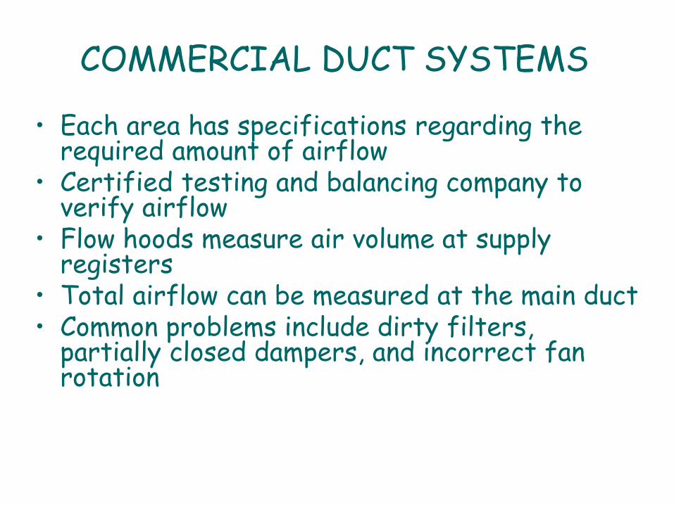
COMMERCIAL DUCT SYSTEMS
• Each area has specifications regarding the required amount of airflow
• Certified testing and balancing company to verify airflow
• Flow hoods measure air volume at supply registers
• Total airflow can be measured at the main duct • Common problems include dirty filters,
partially closed dampers, and incorrect fan rotation
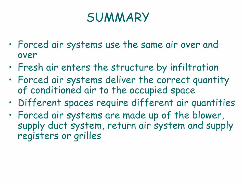
SUMMARY
• Forced air systems use the same air over and over
• Fresh air enters the structure by infiltration• Forced air systems deliver the correct quantity
of conditioned air to the occupied space • Different spaces require different air quantities• Forced air systems are made up of the blower,
supply duct system, return air system and supply registers or grilles

SUMMARY
• Typically, 400 cfm of air must be moved per minute per ton of air conditioning
• Pressure in the ductwork is measured in inches of water column (in. W.C)
• Static pressure plus velocity pressure equals total pressure
• Air volume in cfm can be calculated by multiplying the air velocity by the cross-sectional area of the duct in square feet

SUMMARY
• Propeller fans are used in exhaust fan and condenser fan applications and can handle large volumes of air at low pressure differentials
• Centrifugal blowers are used in duct systems• Motor drives can be direct or belt driven
assemblies• The supply duct system can be configured as a
plenum, extended plenum, reducing extended plenum or perimeter loop system

SUMMARY - 4• Duct systems can be made of galvanized metal,
aluminum, fiberglass duct board, spiral metal, flexible duct or a combination of different materials
• Branch ducts deliver the proper amount of air to remote locations in the structures
• Balancing dampers are used to help ensure proper airflow to the remote locations
• The return air system can be configured as a central or individual return air system

SUMMARY - 5
• Friction in the duct slows the air flowing in it
• Slower air experiences less friction• Air balancing ensures the proper amount of
air is delivered to each supply register• CFM = velocity x cross sectional area• The friction chart is used to properly size
duct systems

Comfort Requirements
Temperature
Humidity
Air movement
Fresh air
Clean air
Noise levels
Lighting
Furniture and work surfaces

The Five System Loops
The premise of this method is that any HVAC system can be dissected into
basic subsystems. These subsystems will be referred to as "loops/" There are
five primary loops that can describe virtually any type of HVAC system.
These five loops can be used to describe virtually any HVAC system, not every
system uses all five loops.
• Airside loop (yellow)
• Chilled-water loop (blue)
• Refrigeration loop (green)
• Heat-rejection loop (red)
• Controls loop (purple)

Airside Loop
Airside Loop
The first loop is the airside loop, and the first component of this loop is the
conditioned space. The first two comfort requirements mentioned were dry-
bulb temperature and humidity. In order to maintain the dry-bulb temperature in
the conditioned space, heat (referred to as sensible heat) must be added or
removed at the same rate as it leaves or enters the space. In order to maintain the
humidity level in the space, moisture (sometimes referred to as latent heat) must
be added or removed at the same rate as it leaves or enters the space.

Supply Fan and FilterThe next component of the airside loop is a
supply fan that delivers the supply air (SA) to
the space.One of the comfort requirements is to
provide an adequate amount of fresh, outdoor air
to the space. The required amount of outdoor air
(OA) for ventilation is brought into the building
and mixed with the re circulated portion of the
return air (RA).
The remaining return air, that which has been
replaced by outdoor air, is exhausted as exhaust
air (EA) from the building, often by an exhaust
(or relief) fan. Outdoor air at 95ºF (35ºC) dry
bulb mixes with re-circulated return air at 75ºF
(23.9ºC) dry bulb.
This mixture contains 25 percent outdoor air and
75 percent re-circulated return air, so the resulting
temperature of the mixed air (MA) is 80ºF
(26.7ºC) dry bulb.

Cooling Coil
The supply air must be cold enough to absorb excess sensible heat from the space
and dry enough to absorb excess moisture (latent heat).
A heat exchanger, commonly known as a cooling coil, is often used to cool and
dehumidify the supply air before it is delivered to the space.
A typical cooling coil includes rows of tubes passing through sheets of formed fins. A
cold fluid, either water or liquid refrigerant, enters one header at the end of the coil
and then flows through the tubes, cooling both the tubes and the fins.

Chilled-Water Cooling CoilA cooling coil that has chilled water
flowing through it. As the warm, humid
mixed air passes through the coil, it
comes into contact with the cold tubes
and fins. Sensible heat is transferred from
the air to the fluid inside the tubes,
causing the air to
be cooled.
Many HVAC systems also use the airside
loop for heating and humidification. Often,
a heating coil or humidifier is located near
the cooling coil in the same airside loop.
Alternatively, a heating coil or humidifier
may be part of a second, separate airside
loop.
Assuming a fixed quantity of air, if the
supply air is warmer, it can add more
sensible heat to the space. If the supply
air is more humid, it can add more
moisture to the space.

part-load operationConstant-Volume System
A constant-volume system provides a
constant quantity of supply air and
varies the supply-air temperature in
response to the changing cooling load
in the space.
A thermostat compares the dry-bulb
temperature in the conditioned space to
a set point. It then modulates cooling
capacity until the space temperature
matches the set point.
constant supply-air quantity
variable supply-air temperature

part-load operationVariable-Air-Volume (VAV) System
A VAV terminal unit is added to the airside loop. Each conditioned space, or
group of similar spaces (called a zone), has a separate VAV terminal unit that
varies the quantity of supply air delivered to that space or zone. The VAV terminal
unit contains an airflow modulation device, typically a rotating-blade damper.

A thermostat compares the dry-bulb
temperature in the conditioned space to a set
point.
It then modulates the quantity of supply air
delivered to the space by changing the
position of the airflow modulation device in the
VAV terminal unit.
The capacity of the supply fan is modulated to
deliver only the quantity of supply air needed,
and cooling capacity is modulated to maintain
a constant supply-air temperature.
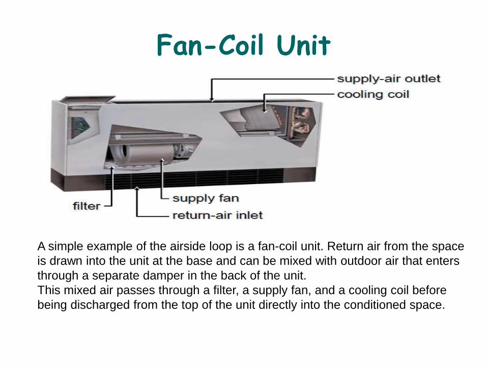
Fan-Coil Unit
A simple example of the airside loop is a fan-coil unit. Return air from the space
is drawn into the unit at the base and can be mixed with outdoor air that enters
through a separate damper in the back of the unit.
This mixed air passes through a filter, a supply fan, and a cooling coil before
being discharged from the top of the unit directly into the conditioned space.

Central Air Handler
A central air handler is typically installed outside of the conditioned space, possibly
on the roof or in a dedicated mechanical room. Return air from the space is drawn
into the unit through the return-air dampers and mixes with outdoor air that enters
through another set of dampers. This mixed air passes through the filters, the supply
fan, and the cooling coil before being discharged from the air handler.
The central air handler needs a method for delivering the supply air to the
conditioned space(s).
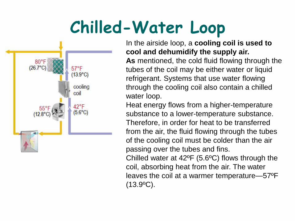
Chilled-Water LoopIn the airside loop, a cooling coil is used to
cool and dehumidify the supply air.
As mentioned, the cold fluid flowing through the
tubes of the coil may be either water or liquid
refrigerant. Systems that use water flowing
through the cooling coil also contain a chilled
water loop.
Heat energy flows from a higher-temperature
substance to a lower-temperature substance.
Therefore, in order for heat to be transferred
from the air, the fluid flowing through the tubes
of the cooling coil must be colder than the air
passing over the tubes and fins.
Chilled water at 42ºF (5.6ºC) flows through the
coil, absorbing heat from the air. The water
leaves the coil at a warmer temperature—57ºF
(13.9ºC).

Evaporator
A heat exchanger is used to cool the water that returns from the coil—at 57ºF
(13.9ºC)—back to the desired supply-water temperature of 42ºF (5.6ºC).
This heat exchanger, called an evaporator, is one component of the
refrigeration (cooling) equipment.

Shell-and-Tube Evaporator
A shell-and-tube evaporator that has cold liquid refrigerant flowing through
the tubes. Warm water enters at one end of the shell and fills the space
surrounding the tubes.
Heat is transferred from the water to the refrigerant inside the tubes, and chilled
water leaves from the opposite end of the shell.

Pump and Control ValveThe third component of the chilled-
water loop is a pump that moves
water around the loop.
This pump needs to have enough
power to move the water through
the piping, the evaporator, the tubes
of the coil, and any other
accessories installed in the chilled-
water loop.
Similar to the airside loop, the chilled-water loop responds to changing cooling loads
by varying either the temperature or the quantity of water delivered to the cooling
coil.The most common method, however, is to vary the quantity of water flowing
through the cooling coil by using a control valve. As the cooling load decreases,
the modulating control valve reduces the rate of chilled-water flow through the
coil, decreasing its cooling capacity.

Two-Way Versus Three-Way Valves
At part-load conditions, a two-way control valve reduces the rate of chilled-water flow
through the coil.
A three-way control valve also reduces the rate of flow through the coil, but it
bypasses the excess water to mix downstream with the water that flows through the
coil.

With a three-way valve, the quantity of water flowing through
the system (water flowing through the coil plus water
bypassing the coil) is constant at all loads. With a two-way
valve, the water flowing through the system varies, which
allows the pump to reduce its capacity and save energy at
part load.
Notice that the control valve is located at the outlet, or
downstream, of the cooling coil.
This location ensures that the tubes inside the coil are
always full of water.
A valve located at the inlet, or upstream, of the coil may
modulate to the point where the water just "trickles“ through
the tubes, not filling the entire tube diameter.
The result is unpredictable heat transfer and less-stable
control.

Small Chilled-Water System
A packaged water chiller produces
chilled water by transferring heat from
the water to the refrigerant inside the
evaporator.
This chilled water flows through the
cooling coils, where it is used to cool and
dehumidify the supply air.
A pump is used to circulate water
through the evaporator, the piping, the
cooling coils, and the control valves.
Finally, each cooling coil is equipped
with a three-way control valve that varies
the rate of chilled-water flow through the
coil in response to changing cooling
loads.

Refrigeration Loop
The third loop is the refrigeration loop.In the chilled-water loop, the evaporator
allows heat to transfer from the water to cold liquid refrigerant.
Liquid refrigerant at 38ºF (3.3ºC) enters the tubes of the shell-and-tube evaporator.
As heat is transferred from the water to the refrigerant, the liquid refrigerant boils.
The resulting refrigerant vapor is further warmed (superheated) to 50ºF (10ºC)
inside the evaporator before being drawn to the compressor.

Compressor
The compressor is used to pump the low-pressure refrigerant vapor from the
evaporator and compress it to a higher pressure. This increase in pressure also
raises the temperature of the refrigerant vapor—120ºF (48.9ºC) .
Common types of compressors used in HVAC systems include reciprocating,
scroll, helical-rotary (screw), and centrifugal.

Condenser
After being discharged from the compressor, the hot, high-pressure refrigerant
vapor enters a condenser. The condenser is a heat exchanger that transfers
heat from the hot refrigerant vapor to air, water, or some other fluid that is at a
colder temperature. As heat is removed from the refrigerant, it condenses and
returns to the liquid phase.

Types of Condensers

A typical air-cooled condenser has the hot, high-pressure refrigerant
vapor flowing through the tubes of a finned-tube heat exchanger and
uses propeller-type fans to draw outdoor air over the outer surfaces of the
tubes and fins.
A variation of the air-cooled condenser is the evaporative condenser.
Within this device, the refrigerant flows through tubes and air is drawn or
blown over the tubes by a fan.
The difference is that water is sprayed on the outer surfaces of the tubes.
As the air passes over the tubes, it causes a small portion of the water to
evaporate. This evaporation process improves the heat transfer from the
condensing refrigerant. The remaining water then falls into the sump to be
re-circulated by a small pump and used again.
The most common type of water-cooled condenser is the shell-and-tube
design. With this design, water flows through the tubes while the hot
refrigerant vapor fills the space surrounding the tubes.
As heat is transferred from the refrigerant to the water, the refrigerant
vapor condenses on the outer surfaces of the tubes and the condensed
liquid refrigerant falls to the bottom of the shell.

Expansion Device
The liquid refrigerant that leaves the condenser is still at a relatively high
temperature-110ºF (43.3ºC) .The final step of the refrigeration cycle is for this
hot liquid refrigerant to pass through an expansion device. This device creates a
large pressure drop that reduces the pressure, and correspondingly the
temperature, of the refrigerant. where it is again cold enough to absorb heat inside
the evaporator.

Helical-Rotary Water Chiller
An example of the refrigeration loop is a packaged, helical-rotary (screw) water
chiller. This example chiller uses an evaporator to produce chilled water by
transferring heat from the water to the liquid refrigerant. The compressor consists of
two screw-like rotors to compress the refrigerant vapor, raising its pressure and
temperature. A second heat exchanger serves as the water-cooled condenser, where
refrigerant is condensed inside the shell and water flows through the tubes. The
expansion device (not shown) used in this chiller is an electronic expansion valve.

Finned-Tube Evaporator (Coil)
Not all HVAC systems use all five loops. So far, we have looked at the airside loop,
the chilled-water loop, and the refrigeration loop.
Instead of chilled water flowing through the tubes of the cooling coil, some systems
have cold liquid refrigerant flowing through the tubes. In this case, the finned-tube
cooling coil is also the evaporator of the refrigeration loop. As air passes through the
coil, heat is transferred from the air to the refrigerant. This heat transfer causes the
refrigerant to boil and leave the evaporator as vapor.

No Chilled-Water Loop
In this arrangement, the chilled-water loop does not exist. Heat is
transferred from the airside loop directly to the refrigeration loop.

Packaged Rooftop Air Conditioner
A system that does not use the chilled-water loop is one that uses a
packaged rooftop air conditioner. It combines several components of the airside loop
with all the components of the refrigeration loop.
Similar to the central air handler shown earlier, return air from the space is drawn
into the unit and is mixed with outdoor air that enters through a separate damper.
This mixed air passes through the filters, the cooling coil (which is also the
evaporator), and the supply fan before it is discharged from the unit. Packaged
inside this same piece of equipment are one or more compressors, an air-cooled
condenser complete with propeller-type fans, and expansion devices.

Heat-Rejection Loop
The fourth loop is the heat-rejection loop. In the refrigeration loop, the condenser transfers heat
from the hot refrigerant to air, water, or some other fluid. In a water-cooled condenser, water
flows through the tubes while the hot refrigerant vapor enters the shell space surrounding the
tubes. Heat is transferred from the refrigerant to the water, warming the water.water enters the
condenser at 85ºF (29.4ºC), absorbs heat from the hot refrigerant, and leaves at 100ºF (37.8ºC).
The water flowing through the condenser must be colder than the hot refrigerant vapor. A heat
exchanger is required to cool the water that returns from the condenser—at 100ºF (37.8ºC)—back
to the desired temperature of 85ºF (29.4ºC) before it is pumped back to the condenser. When a
water-cooled condenser is used, this heat exchanger is typically either a cooling tower or a fluid
cooler (also known as a dry cooler).

Cooling Tower
•In a cooling tower, the warm water returning from the
condenser is sprayed over the fill inside the tower while a
propeller fan draws outdoor air upward through the fill.
•One common type of fill consists of several thin, closely
spaced layers of plastic or wood. The water spreads over the
surface of the fill to increase the contact with the passing air.
The movement of air through the fill allows heat to transfer
from the water to the air.
•This causes some of the water to evaporate, a process that
cools the remaining water. The remaining cooled water then
falls to the tower sump and is returned to the condenser.
A fluid cooler is similar to an air-cooled condenser. Water
flows through the tubes of a finned-tube heat exchanger and
fans draw outdoor air over the surfaces of the tubes and fins.
Heat is transferred from the warmer water to the cooler air.

COOLING TOWER FUNCTION
• Water is moved by a pump from the condenser to the cooling tower and back to the condenser
• Tower must reject more heat than the chiller absorbs• The compressor adds approximately 25% additional heat• Design temperature of water leaving the tower is 85°• The tower can cool the water down to within 7° of the
wet-bulb temperature of the ambient air (approach)• Cools the water by evaporation
– As air is passed over the water, some of it evaporates– This evaporating water cools the remaining water

Cooled water out (85°F)
Hot water in (95°F)
Air in 95°F dry bulb, 78°F wet
bulb
Air out
Fan motor

Condenser
Evaporator
Load85°F water
95°F water
Pump
45°F
55°F
Pump

TYPES OF COOLING TOWERS
• Natural draft towers rely on prevailing winds
• Forced/induced draft towers use a fan to move air through the tower – Fans can be gear-driven or belt-driven
• Closed-loop hybrid tower– Dry/wet mode, adiabatic mode, and dry mode

Prevailing winds
Make-up water
Float Valve
Warm water from condenser
Slats on all four sides of
the towerSpray nozzles
Water to pump
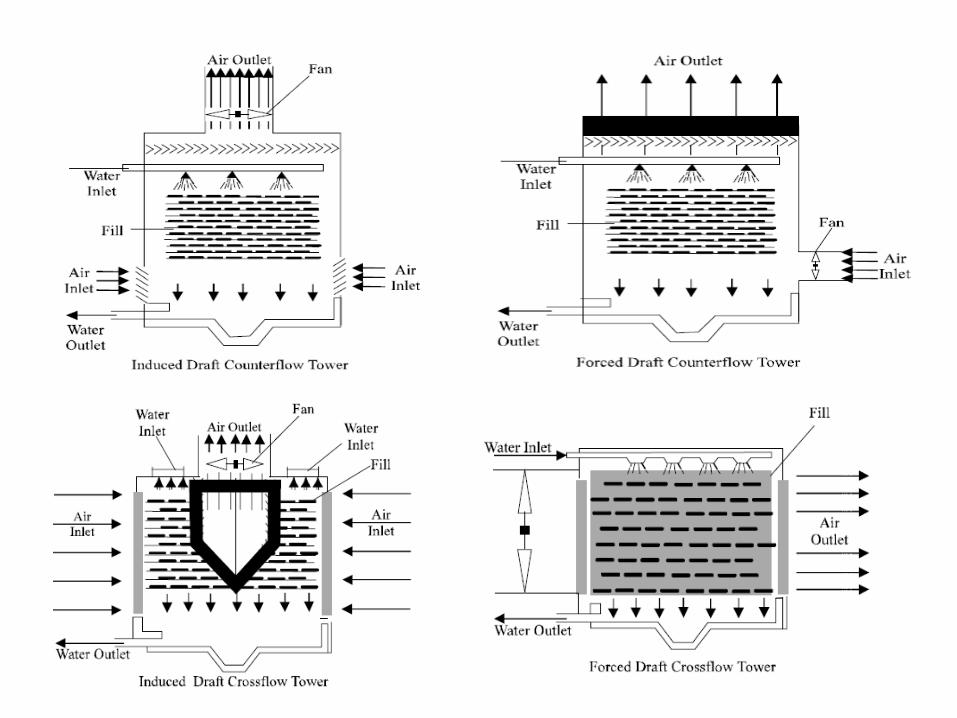


DRY/WET MODE
• Fluid to be cooled is fed first to the dry finned coil
• Fluid then fed to the prime surface coil• Fluid then leaves tower• Water in the tower flows over the prime
surface coil and wet deck surface• Air is drawn through the prime surface coil
and wet deck surface


ADIABATIC MODE
• Condenser water is cooled by evaporating the tower water
• No heat is added or removed during from the process
• Fluid to be cooled passes only through finned coil
• Spray water is used to help cool the air passing through the tower
• Plume is the saturated discharge air


DRY MODE
• Fluid to be cooled passes through the finned coil and the primed surface coil
• No spray water is used
• No plume results
• Fluid is cooled by air passing over the coil

FIRE PROTECTION
• The off season can create a fire hazard
• Tower components may be flammable
• A tower wetting system may be required
• Some towers are kept wet whenever the temperature is above freezing

FILL MATERIAL
• Designed to slow the flow of trickling water through the tower
• Splash method – Uses wood slats, PVC pipe, or FRP plastic
– Tower has framework to support slats at the correct angle
• Film or wetted surface – Fill is usually plastic or fiberglass
– The water is spread out over the fill as air is passed over it

FLOW PATTERNS
• Crossflow– Air enters from the side and is discharged from
the top or the other side
• Counterflow – Air enters from the bottom and is exhausted at
the top
– The water flows down as the air moves up
• Water that is blown out of the tower is called drift
• Eliminators reduce the amount of drift

TOWER MATERIALS
• Must withstand the environment
• Must withstand fan and drive mechanism vibrations
• Usually made of galvanized steel, fiberglass, or FRP
• Larger towers may have a concrete base
• The sides of the tower can be made of wood, fiberglass, corrugated FRP

FAN SECTION
• Belt-driven fan – Primarily found on smaller towers
• Gear box transmissions – Motors are usually mounted at a 90
degree angle to the fan
– May be designed to reduced the fan speed
– Motor, gear box, and bearings must be accessible for servicing

TOWER ACCESS
• Tower fill must be accessible for cleaning or replacement
• Sludge needs to be cleaned from the tower basin
• Garbage, bird features, and other pollutants accumulate in the sump
• There is a strainer to prevent garbage from entering the pump and water circuit
• Stairs or ladders provide access to fans and drive mechanisms on tall towers

TOWER SUMP
• Area where tower water collects
• Sump water must not freeze
• May be installed underground
• Should be accessible for cleaning
• Is usually equipped with a strainer to protect the pump

Prevailing winds
Make-up water
Float Valve
Warm water from condenser
Slats on all four sides of
the towerSpray nozzles
Water to pumpThermostatically controlled heater

MAKE-UP WATER • Water continuously evaporates from the
system • Fresh water must be supplied to the
system as needed • Float valve
– As the water level drops, the valve will open and add supply water
• Solenoid controlled valve – Solenoid valve operation controlled by a float
switch • Electrodes
– Used to sense the water level

To pumpStrainer
Make up water
Float ball
Float valve
Water level
Float and Valve

Water level
To pumpStrainer
Make up water
Float ball
Float Switch and Solenoid
Float switch
Solenoid

To pumpStrainer
Electronic Water Level Control
Solenoid
Control Sensors

BLOWDOWN
• Process of bleeding off a portion of the system water
• This water is replaced with fresh water
• Designed to reduce the amount of solid materials in the water
• Blowdown reduces head pressure and approach temperature
• Must be done correctly

BALANCING THE WATER FLOW FOR A TOWER
• Water flow to each of tower cell must be equal
• Distribution pans – Receives water returning from the condenser
– Have calibrated holes to distribute water
– Holes must be clean
• Balancing valves must be adjusted properly
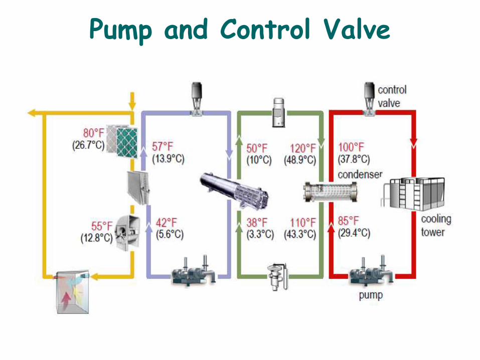
Pump and Control Valve
• The third component of the heat-rejection loop moves the condensing media
around the loop. In the case of a water-cooled condenser, a pump is needed to
move the water through the tubes of the condenser, the piping, the cooling tower,
and any other accessories installed in the heat-rejection loop.
• The heat-rejection capacity of this loop can be varied in response to changing
heat-rejection requirements. In the case of a water-cooled condenser, this is
commonly accomplished by varying the temperature of water delivered to the
condenser.
• Varying the temperature of the entering condenser water may be accomplished
by using variable-speed fans in the cooling tower or by cycling the fans on and
off.
•One method of varying the quantity of water flowing through the water-cooled
condenser is to use a modulating control valve.
• As the heat-rejection requirement decreases, the modulating control valve
directs less water through the condenser. If a three-way valve is used, the
excess water bypasses the condenser and mixes downstream with the water
that flows through the condenser.
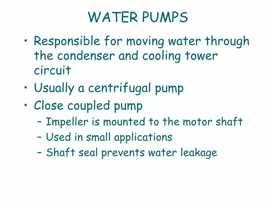
WATER PUMPS
• Responsible for moving water through the condenser and cooling tower circuit
• Usually a centrifugal pump
• Close coupled pump – Impeller is mounted to the motor shaft
– Used in small applications
– Shaft seal prevents water leakage

WATER PUMPS
• Base mounted pump – Motor and pump are connected by a
flexible coupling
– Can have a single- or double-sided impeller
– Motor and pump are mounted on a base
– Base is usually cemented to the floor
– Motor and pump are factor aligned

WATER PUMPS
• Pump must have a shaft seal • Most pumps are made from cast iron • Most centrifugal pump impellers are made of
bronze • The eye of the impeller must be under water
during startup • If the pump is located higher than the sump, the
pump must be filled with water before starting• Whirlpool action in the pump is called vortexing

WATER PUMPS
• Strainers are located between the sump and pump
• Tower bypass valve– Helps to maintain correct water pressure during
start-up and low-ambient conditions
– Water from the pump outlet is recirculated to the pump inlet
• Pumps can have sleeve bearing or ball bearings
• Pumps and shafts must be properly aligned

Water Chiller and Cooling Tower•The water-cooled condenser
on this chiller transfers heat
from the refrigerant to the
water in the loop.
•This water passes through a
cooling tower and heat is
rejected to outdoor air passing
through the tower.
•A pump is used to circulate
water through the condenser,
the piping, the cooling tower,
and the control valve.
Finally, a modulating, three-way control valve is used to vary the water flow through
the condenser in response to a changing heat-rejection requirement. This valve
modulates the water flow through the condenser by diverting some of the water
around the condenser through the bypass pipe, directly back to the cooling tower.

Packaged Air-Cooled Chiller
Another example of the heat-rejection loop is a packaged, air-cooled chiller. It
combines all the components of the refrigeration and heat-rejection loops.
This example air-cooled chiller contains an evaporator, two or more compressors,
an aircooled condenser coil, and expansion devices. Propeller-type condenser fans
draw outdoor air across the condenser coil.

Packaged Air-Cooled Chiller
In the case of an air-cooled condenser, heat is transferred from the hot refrigerant
vapor directly to the outdoor air without the need for a separate condenser-water
loop.
As the heat-rejection requirement decreases, the quantity of air passing through the
condenser coil(s) is reduced. This is accomplished by cycling the condenser fans on
and off, or by modulating a damper or variable-speed drive on one or more of the
fans.

Controls Loop
•The fifth, and final, loop of the HVAC system is the controls loop. Each of
the previous four loops contains several components. Each component must
be controlled in a particular way to ensure proper operation.
•Typically, each piece of equipment (which may be comprised of one or
more components of a loop) is equipped with a unit-level, automatic
controller.
•In order to provide intelligent, coordinated control so that the individual
pieces of equipment operate together as an efficient system, these individual
unit-level controllers are often connected to a central, system-level
controller.
•Finally, many building operators want to monitor the system, receive alarms
and diagnostics at a central location, and integrate the HVAC system with
other systems in the building.
•These are some of the functions provided by a building automation
system (BAS).

Rooftop VAV SystemThis system uses a
packaged rooftop air
conditioner to deliver air to
several VAV terminal units.
This packaged rooftop air
conditioner includes a unit-
level controller that
coordinates the operation of
all components packaged
inside this piece of
equipment, such as the
outdoor-air and return-air
dampers, the supply and
exhaust fans, the
compressors, and the
condenser fans.
In addition, each VAV terminal unit is equipped with a unit-level controller that
directs its response to space conditions.
The system-level controller coordinates the operation of the VAV terminal units and
the rooftop unit during the various modes of operation, such as occupied,
unoccupied, and morning warm up.

Air-Cooled Chiller, Fan-Coil System

•This system includes fan-coil units served by an air-cooled chiller
and a hot-water boiler. A fan-coil unit is located in or near each
conditioned space, and each one includes its own unit-level
controller to modulate water flow through the coil in response to
the changing load in the space.
•The unit-level controller on the air-cooled water chiller ensures
the flow of chilled water whenever it is required, and the boiler
controller ensures the flow of hot water whenever it is required.
•Finally, a dedicated outdoor-air unit conditions all of the outdoor
air brought into the building for ventilation, before delivering it
directly to the individual spaces.
•In this example, a separate, system-level controller coordinates
starting and stopping the pumps, the dedicated outdoor-air unit,
and the stand-alone exhaust fan.
•It also determines when to change over from cooling to heating
mode, and coordinates the operation of the chiller and boiler to
prevent them from operating simultaneously.

Direct Expansion (DX) VersusChilled-Water Systems
Some HVAC systems have chilled water flowing
through the tubes of the cooling coil. These
systems are referred to as chilled-water systems.
Other systems have cold, liquid refrigerant
flowing directly through the tubes of the cooling
coil. These are referred to as direct-expansion, or
DX, systems.

Direct Expansion (DX)

Direct-Expansion (DX) Systems
The term "direct" refers to the position of the evaporator
with respect to the airside loop. In a direct-expansion
system, the finned-tube cooling coil of the airside
loop is also the evaporator of the refrigeration loop. The
evaporator is in direct contact with the airstream.
The term "expansion" refers to the method used to
introduce the refrigerant into the cooling coil. The liquid
refrigerant passes through an expansion device just
before entering the cooling coil (evaporator). This device,
reduces the pressure and temperature of the refrigerant
to the point where it is colder than the air passing through
the coil.

Air-Cooled DX System
The primary difference between a chilled-water system and a direct-expansion
system is that the DX system does not include the chilled-water loop. Instead,
heat is transferred from the airside loop directly to the refrigeration loop.
In this case, the components of the heat rejection loop are packaged together.
The air-cooled condenser contains propeller-type fans that draw outdoor air
across the finned-tube condenser coils. Heat is transferred from the
hot refrigerant vapor directly to the outdoor air without the use of a separate
condenser water loop.
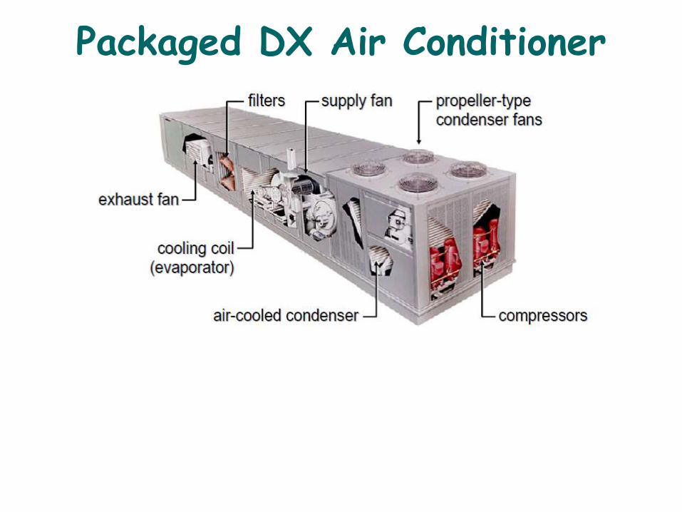
Packaged DX Air Conditioner

In a DX system, the components of the refrigeration loop may be packaged
together or split apart. A packaged DX unit includes all the components of the
refrigeration loop (evaporator, compressor, condenser, and expansion device)
inside a single casing.
The packaged rooftop air conditioner was introduced in Period One.
It combines several components of the airside loop with all the components of
both the refrigeration and heat rejection loops.
This type of equipment is intended for outdoor installation, commonly on the roof
of a building.
A major advantage of a packaged DX unit is the factory assembly and testing of
all components, including the electrical wiring, the refrigerant piping, and the
controls.
It is important to recognize that the allowable distance between the components
of a split system is limited to ensure reliable operation. Refrigerant does not flow
like water.
Refrigerant is in a vapor state during part of its cycle and in a liquid state during
the remainder of its cycle. Oil, used to lubricate the compressor, is often carried
along by the refrigerant as it flows throughout the system.
The sizing and layout of the refrigerant piping is critically important in ensuring
that the oil is returned to the compressor at the required rate.
All components, including the refrigerant piping and controls, must be carefully
selected to work properly over the desired range of operating conditions.

Chilled-Water Loop
In a chilled-water system, the chilled-water loop transports heat
energy between the airside loop and the refrigeration loop.
It is comprised primarily of a cooling coil, a circulating pump, an evaporator,
a control valve, and interconnecting piping.

Packaged Water Chillers
In a chilled-water system, the components of the refrigeration loop (evaporator,
compressor, condenser, and expansion device) are often manufactured, assembled,
and tested as a complete package within the factory. This type of equipment is called
a "packaged" water chiller, and may include either a water-cooled condenser or an
air-cooled condenser. The components are selected and optimized by the
manufacturer, and the performance is tested as a complete assembly, rather than as
individual components.
A major advantage of this configuration is factory assembly and testing of all chiller
components, including the electrical wiring, the refrigerant piping, and the controls.
This eliminates field labor and often results in faster installation and improved
reliability.

Split Chilled-Water System

Alternatively, the components of the refrigeration loop may be split apart. While
water-cooled chillers are rarely installed as separate components, some air-cooled
chillers offer the flexibility of separating the components for installation in different
locations.
This flexibility allows the system design engineer to place the components where
they best serve the space, acoustic, and maintenance requirements of the building
owner.
The other components of the refrigeration loop (evaporator and expansion device)
are installed inside the building. These components are connected to the
condensing unit with field-installed refrigerant piping. This configuration places the
part of the system that is susceptible to freezing (evaporator and water piping)
indoors, and the primary noise-generating components of the refrigeration loop
(compressors and condenser fans) outdoors.
This usually eliminates any requirement to protect the chilled-water loop from
freezing during cold weather.
A drawback of splitting the components is the requirement for field-installed
refrigerant piping. The possibility of system contamination and leaks increases
when field-installed piping and brazing are required.
Additionally, the components must be properly selected to work together over the
desired range of operating conditions. With a packaged water chiller, the selection
of the components, and the design and installation of the refrigerant piping, is
handled by the manufacturer in the factory.

DX versus chilled waterFactors Affecting the Decision
One of the most common reasons for selecting a DX system, especially a
packaged DX system, is that, in a smaller building, it can frequently have a
lower installed cost than a chilled-water system.

Installed Cost
In the DX system, the chilled-water pumps, the control valves, the piping, and related
accessories are eliminated.
Packaged DX equipment generally requires less field labor and materials to install.
Also, many of the system-level control functions can be packaged along with the
unit-level control functions in the same piece of control hardware. This can reduce
the amount of time it takes to design, install, and commission the control system.
If a split DX system is used, there is an added cost for designing and installing the
refrigerant piping and controls.

Energy Consumption
Decisions based solely or primarily on installed cost often ignore ongoing costs,
such as energy, maintenance, and replacement costs. Life-cycle cost includes the
total cost of owning and operating the HVAC system over a specified period of
years.
A DX system does not have the added energy use of the pumps, but the larger
compressor on the water chiller is often more efficient than the compressor in the
DX unit.

Space Requirements
Another common reason for selecting a DX system is limited space available for
indoor equipment rooms. Water-cooled, chilled-water systems frequently require
indoor equipment rooms to house the chillers and pumps.
Air-cooled, chilled-water systems require less space indoors, but may still need
space for the evaporator and/or pumps. Indoor equipment rooms reduce the
amount of usable or rentable floor space.

Freeze Prevention
In many climates, the outdoor temperatures drop below 32ºF (0ºC) at some point
during the year.
Systems that contain water are at risk of freezing when the piping or other
components of the chilled-water loop are exposed to these cold ambient
temperatures, or if the refrigeration equipment cools the water to a temperature
below 32°F (0°C).
Air-cooled DX systems, however, use refrigerant as the heat-transfer media and
are not at risk for freezing under these conditions.

A common approach used to prevent freezing in a chilled-water system is to use a
mixture of water and antifreeze, such as ethylene glycol or propylene glycol. This
lowers the freezing point of the fluid mixture. Here shows the freezing point for
various concentrations of water-and-ethylene-glycol solutions.
If 20 percent (by weight) of the solution is ethylene glycol and 80 percent is water,
the temperature at which this mixture will begin to freeze is 15.5°F (-9.1°C),
compared to 32°F (0°C) for pure water.
Realize that there are two levels of freeze prevention: burst protection and freeze
protection. As the temperature drops below the freezing point of the solution, ice
crystals begin to form. Because the water freezes first, the remaining water–glycol
solution is further concentrated and remains in the liquid phase. The combination
of ice crystals and remaining water–glycol solution makes a flowable slush, but the
volume increases as this slush forms.
If the chilled-water loop has an expansion tank large enough to accommodate
this increase in volume, and if the water–glycol solution does not need to be
pumped during below-freezing weather, burst protection is usually sufficient to
prevent damage to the system.
If the chilled-water loop does not have adequate expansion volume, or if the
water–glycol solution must be pumped during below-freezing weather, freeze
protection is probably required.

System Capacity
Packaged water chillers are typically available in sizes ranging from 7.5 to
approximately 4,000 tons (25 to 14,000 kW). Direct-expansion equipment is
typically available in sizes ranging from 1 to 200 tons (3.5 to 704 kW).
In large buildings, a chilled-water system generally consists of fewer pieces of
refrigeration equipment than a DX system.

System Categories
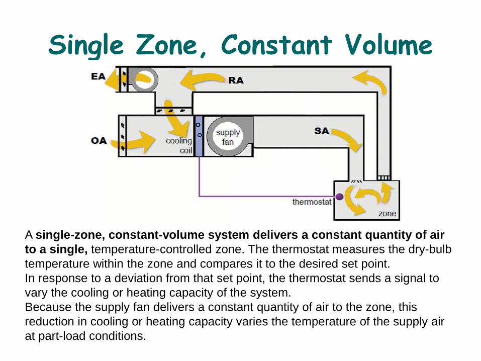
Single Zone, Constant Volume
A single-zone, constant-volume system delivers a constant quantity of air
to a single, temperature-controlled zone. The thermostat measures the dry-bulb
temperature within the zone and compares it to the desired set point.
In response to a deviation from that set point, the thermostat sends a signal to
vary the cooling or heating capacity of the system.
Because the supply fan delivers a constant quantity of air to the zone, this
reduction in cooling or heating capacity varies the temperature of the supply air
at part-load conditions.

single-zone systems Single Thermostat
If the zone is comprised of multiple conditioned spaces, the space in which the
thermostat is located dictates the operation of the HVAC system. All other spaces
must accept the resulting level of comfort based on the space containing the
thermostat. If the thermostat calls for more cooling, all spaces get more cooling.
Therefore, in a building with this type of system, it is common to use several single-
zone systems to satisfy the different thermal requirements of the building.

single zone, constant volumePackaged Terminal Air Conditioner

A simple example of a single-zone, constant-volume system is a
packaged
terminal air conditioner (PTAC).
This type of equipment contains several components of the airside
loop and all the components of the refrigeration, heat-rejection, and
controls
loops, inside a common casing.
PTAC units are typically installed in the perimeter wall of the building,
which allows the aircooled condenser to reject heat directly to the
outdoors. They are commonly used in hotels,dormitories, nursing homes,
and apartments.
In this example PTAC, return air from the occupied space is drawn in
through the front grille, and passes through a filter and DX cooling coil
before the supply fan discharges the air from the top of the unit directly
into the occupied space.
Outdoor air for ventilation can enter through a separate damper and mix
with the recirculated air, or it can be delivered to the conditioned space by
a dedicated outdoor-air ventilation system.
Packaged inside this same piece of equipment is a compressor, an air-
cooled condenser coil, a condenser fan, an expansion device, and all the
controls.

single zone, constant volumePackaged DX Rooftop System
Another example of a single-zone, constant-volume system (Figure 63) is a
packaged DX rooftop unit. Like the PTAC, this unit includes several
components of the airside loop, all the components of the refrigeration and heat-
rejection loops, and most of the components of the controls loop, inside a common
casing. The conditioned air, however, is discharged from the unit into the supply
ductwork and is delivered to the occupied space(s) through supply diffusers.


single zone, constant volumeChilled-Water Terminal System
Single-zone, constant-volume systems may also use chilled water as the cooling
media. In the case of this chilled-water terminal system, chilled water and hot
water are produced at a central location and pumped throughout the building to
individual terminal units that are installed in or near each zone.

Dedicated Outdoor-Air System

Single Zone, Variable Volume
A single-zone, variable-volume (VAV) system varies the quantity of
constant-temperature air delivered to one temperature-controlled zone.
Again, a zone may be either a single space, or a group of spaces that react
thermally in a similar manner over time, and are governed by one thermostat.
Unlike a traditional multiple-zone VAV system, the single-zone VAV system
uses no VAV terminal boxes to vary airflow to the zone.
Instead, fan capacity is modulated in direct response to the zone thermostat.

Multiple Zones, Constant Volume
A multiple-zone, constant-volume system uses a central supply fan and
cooling coil to deliver a constant quantity of air to several individually controlled
zones.The central cooling coil cools and dehumidifies the supply air to a particular
leaving-air temperature.

multiple zones, constant volumeMulti zone Air Handler
multizone system, uses a central air handler that contains both a cooling coil
and a heating coil, and several pairs of dampers located at the discharge of the
air handler. Each pair of "cooling" and "heating" zone dampers is controlled by a
thermostat in the zone served by the damper pair. After passing through this pair of
dampers, the supply air is delivered to the individual zones through separate,
dedicated supply ducts.

multiple zones, constant volumeChangeover–Bypass System
Many smaller buildings, however, cannot afford to install a large number of single-
zone units or a more-advanced multiple-zone system. An economical alternative
may be to use a changeover–bypass system, which uses traditional, single-zone
HVAC equipment, but allows independent control for multiple zones.
A changeover–bypass system includes an airflow modulation device, typically a
rotating blade damper, for each individually controlled zone.

multiple zones, constant volumeChangeover–Bypass System
In response to the varying load, a thermostat in each zone instructs the
modulating damper to vary the quantity of supply air delivered to that zone. The
bypass duct also contains a damper that is modulated to prevent too much supply
air from bypassing to the return airstream.
A changeover–bypass system cannot accommodate a demand for simultaneous
cooling and heating, because the HVAC unit operates in either the cooling mode
or the heating mode.

Multiple Zones, Variable Volume
A multiple-zone, variable-volume (VAV) system consists of a central air
handler that serves several individually controlled zones. Each zone has a
VAV terminal unit (VAV box) that is controlled by a thermostat in the zone.

multiple zones, variable volumeVAV Terminal Units

The cooling-only VAV terminal unit consists of an airflow modulation
device with controls packaged inside a sheet-metal enclosure. This VAV terminal
unit can modulate the supply airflow to the zone, and is typically used for those
zones that require year-round cooling, like the interior zones of a building.
The VAV reheat terminal unit also contains an airflow-modulation device
and controls, but it has an electric or hot-water heating coil added to the
discharge of the terminal unit. The heating coil is turned on when the supply
airflow has been reduced to a minimum setting.
The parallel fan-powered VAV terminal unit has this small fan configured
inside the terminal unit to provide parallel airflow paths. The terminal-unit fan
cycles on only when the zone requires heating. The fan draws warm air from the
ceiling plenum to raise the temperature of the air supplied to the zone.
The series fan-powered VAV terminal unit has the fan configured inside the
terminal unit so the airflow paths are in series. The terminal-unit fan operates
continuously whenever the zone is occupied, and draws air from either the
primary air stream or the ceiling plenum, based on the cooling or heating
requirement of the zone.

multiple zones, variable volumeDX Rooftop VAV System
Supply air is discharged from the unit and travels
down a central supply shaft before being distributed
through the ductwork that is located in the ceiling
plenum above each floor. The supply ductwork
delivers air to the VAV terminal units. Each VAV
terminal unit is controlled by a thermostat in the zone it
serves, and varies the quantity of air delivered to that
zone.
A multiple-zone,
variable-volume system
is the packaged
rooftop VAV system.
A large, packaged DX
rooftop unit is located
outdoors and
contains several
components of the
airside loop, as well as
all the components of
the refrigeration and
heat-rejection loops. A
building may use a
single rooftop unit or
several units,
depending on its size,
load characteristics,
and function.

multiple zones, variable volumeSelf-Contained DX VAV System
Similar to a packaged rooftop unit, a packaged, self-contained DX unit combines
several components of the airside loop with all the components of the refrigeration
loop and some components of the heat-rejection loop. One or more of these units
are typically installed in a small equipment room on each floor of the building.

multiple zones, variable volumeCentral Chilled-Water VAV System
each floor. The supply ductwork is connected to the VAV terminal units that serve
each zone. Air returns from the zones through the open ceiling plenum into the
equipment room, where it is drawn back into the air handler.
The chilled water is provided by a water-cooled chiller that is located in the
basement, along with the chilled-water and condenser-water pumps. A cooling
tower is located on the roof.
a chilled-water air
handler is located in
an equipment room
on each floor of the
building. Each air
handler is equipped
with a variable-
volume supply fan,
and discharges
conditioned supply air
into ductwork located
in the ceiling plenum
above

multiple zones, variable volumeTwo-Fan, Dual-Duct VAV System
The multiple-zone VAV
system introduced
earlier used a single
supply duct to deliver
conditioned supply air
to multiple, individually
controlled zones.
Another type of multiple
zone VAV system is the
dual-duct VAV
system.
Inside the "heating" air handler, the remainder of the re-circulated return air is
heated, and delivered as warm primary airflow through the "hot" supply-duct
system to the other airflow modulation device in each dual-duct VAV terminal unit.

multiple zones, variable volumeDual-Duct VAV Terminal Unit
A dual-duct VAV terminal unit
(Figure 84) consists of two
airflow-modulation devices,
along
with controls, packaged
inside a sheet-metal
enclosure. One modulation
device varies the
amount of cold primary air
and the other varies the
amount of warm primary air.
These two air streams mix inside the dual-duct unit before proceeding downstream
to the zone. A dual duct VAV terminal unit can be controlled to provide either a
variable volume or a constant volume of supply air to the zone. Dual-duct VAV
systems are intended for buildings that require seasonal cooling and heating.

Typical HVAC processes - AHU
• Air handling units are used for circulating air inside a
building or a part of a building
• Typically consists of two fans (exhaust and supply),
filters, a heat recovery unit, and one or more coils for
heating/cooling
• To improve air quality circulating air is mixed with
fresh air.
• Usually equipped with a heat recovery unit for energy
saving purposes
• Supply air temperature kept constant so that
temperature can be adjusted locally with thermostats

Typical HVAC processes - FAHU
•Fresh air handling units are used for supplying fresh
air inside a building or part of a building
• Indoor air quality is improved as the serving area is
treated with 100% fresh air
• Usually takes more energy to heat/cool fresh air to
target temperature
• Usually equipped with a heat recovery unit for energy
saving purposes
• Can also be used for supplying pre cooled air for
FCUs
Typical HVAC processes –Exhaust fans
•Used for extracting air from the building or part of
a building
• Ventilated areas are usually toilets, kitchens and
other areas where fumes should be extracted
directly outside.
•Parking areas are usually equipped with exhaust
fans that are controlled according to carbon
monoxide measurements or time schedules

Typical HVAC processes – FCUs
• Fan coil units are used for cooling purposes in small areas
• Consist of a blower and a cooling coil
• Can either circulate the air inside the serving area or are supplied with pre cooled air from an air-handling unit

Typical HVAC processes - VAV
•Variable air volume systems are used for
controlling the air flow of constant temperature in
different parts of the building
•Dampers inside ducts regulate the flow of air to
different serving areas
•Pressure difference measurements accross supply
and exhaust fans are used for maintaining a
constant pressure inside ducts
•Thermostats inside serving areas are used for
local set point adjustments that affect the air flow
through dampers.

Typical plumbing processes –Transfer pumps
• Transfer pumps are used for pumping liquid from one place to another
• In residential and office buildings they are typically used for maintaining adequate supply of water in water tanks
• Usually On/Off controlled according to liquid level switches

Typical plumbing processes –Booster pumps
•Booster pumps are used in applications where
the normal system pressure is low and needs to be
increased
•Typical in high rise buildings where domestic
water pipeline pressure needs to be high to better
serve tenants in the upper floors
•Pipeline usually divided into a high and low
pressure zone (lower and higher floors)
•Either PRV or VSD controlled

Typical plumbing processes –Sump pumps
•Sump pumps are used to remove water that has
accumulated in a sump pit
•Sump pumps are usually controlled with two level
switches: higher switch for indicating when the
pump should start and a lower switch for
indicating when the pump should stop
•Pump should not be let run dry so the lower level
switch should be above the pump, upper level
switch should be located near the top.

Typical plumbing processes –Water tanks
•Water tanks are used for storing e.g.
domestic water in high rise buildings
•High and low level switches are used for
alarming and controlling transfer pumps
•More accurate level indication can be
obtained with a pressure difference
transducer.

Typical chilled water processes –Chillers
•Chillers transfer heat from a liquid to the
surrounding air
•Consist of a primary pump and a heat exchanger
• Chilled fluid is used by air handling units and
FCUs to cool supply air temperature
•Usually more than one chiller is used so that
some of them are on standby and are taken into
use when more cooling power is needed.
•Usually controlled according to return
temperature

Typical chilled water processes –Secondary Pumps
•Secondary pumps maintain adequate system
pressure in a chilled water system
•Usually a pump set that consists of several pumps
equipped with variable frequency drives are used
• As with chillers, when the cooling power (pressure)
needed is very low only one pump should be running
and the others on standby
• When more cooling is needed more pumps should
be started
•Controlled according to the pressure difference
between the return and supply headers

Secondary Pumps Control Diagram
Building air conditioning system works on refrigeration principles, using cooling medium to lower the indoor air temperature. The heat absorbed by the refrigerant is then rejected to the outdoor environment either directly to the atmosphere (i.e. air-cooled), by evaporation through cooling towers, or by seawater discharge to the sea (i.e. water-cooled). The last two heat rejection methods can be categorized as water-cooled method because they use water (either fresh water or seawater) as a heat rejection medium.
Water-cooled air conditioning systemTechnology outline

•The air conditioning system uses evaporative cooling tower for heat rejection. Water in cooling tower will be lost due to continuous evaporation, bleed-off and wind drift. The water lost will be replaced by water coming from the city water mains.
a) Cooling Tower Scheme

•The air conditioning system uses seawater for heat rejection. A dedicated central sea water supply distributes seawater from the sea to the user building. The rejected warm seawater from the condenser will be returned to the sea via dedicated pipe.
b) Central Sea Water Scheme


•Chilled water is produced by central chilled water plant. Individual user purchases chilled water for their building from the district cooling scheme operator and do not need to install their own chiller plants. For this scheme, a central chillerplant, a pump house and a central distribution pipeline network are required.
c) District Cooling Scheme

How it can save energy:
Water-cooled air conditioning system rejects heat depending on the ambient
wet-bulb temperature rather than the dry-bulb temperature, so the refrigerant
can be cooled to a lower temperature. This results in a better system
coefficient of performance (COP) and thus more energy efficient.
How much energy can be saved?
A study commissioned by the Electrical and Mechanical Services Department
(EMSD) showed that the District Cooling Scheme and Cooling Tower Scheme
are more efficient than conventional air-cooled system as much as 35% and
20% respectively

Primary and secondary
pumps

• There are basically 3 flow conditions in
primary and secondary pumbing system
1. Primary flow equals secondary flow
2. Secondary flow is greater than primary
flow
3. Primary flow is greater than secondary
flow

Primary flow equals secondary flow

• The chiller is supplying 1500 GPM of 45°F
water to the load systems.
• Because the load is equal to 625 tons, the
return water temperature to the chiller is
55°F at a flow rate of 1500 GPM. The
thermal balance is complete. There is no
flow in the common pipe.

Secondary Flow Greater Than
Primary Flow

To increase the flow rate to 2000 GPM.
The one chiller that is operating will accept
only 1500 GPM and to balance the mass
flow, the excess 500 GPM must run
through the common pipe.Look also at the
temperature relationships.

The temperature of the 500 GPM in the
common pipe is 55°F. This blends with the
1500 GPM of 45°F supply water, resulting
in 2000 GPM of 47.5°F blended supply
water

To deal with this situation, they will
immediately start additional chiller that will
result in primary flows greater than the
secondary This requirement leads to a
simple design rule:

“primary circuit flow should equal or
slightly exceed secondary circuit design
flow rate”. In short, flow in the reverse
primary direction in a de-coupler bridge is
not good.

Primary flow greater than
secondary flow

The flow rate through two chillers is fixed, this time at 3000
GPM. The new secondary load is say 875 tons, which
corresponds to demand rate of 2100 GPM at10 º F delta -T
across the cooling coils. There will be excess flow of 900
GPM in de-coupler as 2100 GPM circulates in the
secondary loop and 3000 GPM is being pumped into the
primary loop.

Look at temperature relationships. The 900
GPM common flow at45ºF blends with the
2100 GPM at 55°F to produce 3000 GPM at
52ºF. This is lower than the desired return
water temperature of 55°F, which makes it
impossible to fully load the “on-line” chillers
and robs the plant of its rated
capacity…..low ΔT syndrome.

Advantages
• Constant Flow through Evaporator
• Simplified Controls
• Past Experience
• Divided Hydraulic Head

Disadvantages
• Does not resolve Low ΔT Syndrome:
• Capital Investment:
• Higher Operating and Energy Costs:
• Requires More Plant Space:

constant primary and constant
secondary

• Primary pumps are lower horsepower than the secondary pumps because they only have to overcome the friction loss associated with the chiller, pipes, and valves in the primary loop. The secondary pumps, in contrast, are higher horsepower because they must overcome the friction loss associated with the secondary loop: the distribution piping, fittings, valves, coils, etc. The secondary loop contains 3-way valves to vary chilled water quantity through the coil in response to load but the total quantity of flow in secondary loop remains the same.

constant primary and variable
secondary

• The constant speed pumps in secondary
circuit are replaced with “variable speed”
pumps. The speed of the secondary
pumps is determined by a controller
measuring differential pressure (DP)
across the supply-return mains or across
the selected critical zones. The decoupled
section isolates the two systems
hydraulically

• Also the system uses two-way valves in the air
handlers that modulate secondary loop flow rate
with load requirements. During light load
condition, the 2-way control valves will close
partially or fully in response to load conditions,
resulting in pressure rise in the secondary
chilled water loop. A differential pressure sensor
measures the pressure rise in the secondary
loop and signals variable frequency drive of
secondary pumps to alter the speed

• Primary-secondary variable-flow systems
are more energy efficient than constant-
flow systems, because they allow the
secondary variable-speed pump to use
only as much energy as necessary to
meet the system demand. Refer to the
schematic below.

primary pumps
CONSTANT FLOW CHILLED WATER SYSTEM
A constant flow system is the simplest
chilled water distribution scheme. Here, a
set of constant speed pumps distributes
fixed quantity of water at all times and the
temperature varies to meet the load.

The system uses 3-way control valves at air
handler coils that allow some water to
bypass the cooling coil during part load
conditions. At low loads, the chilled water
flow through the cooling coil is restricted
but the total quantity returned to the chiller
remains constant


Tandem pumps

Here each pump is dedicated to its respective
chiller i.e. pump 1 is piped directly to chiller 1
and whenever this chiller is operating its \
dedicated pump should be operating.Another
benefit of dedicated pumps is that they can
handle unequally sized chillers without using
control valves and .

flow measurement devices to balance
the correct flow to each chiller The downside is that a standby pump cannot be started automatically by the building control system, but instead needs manual intervention.

Headered pump

This gives the users the ability to use any
pump for the system.This is a advatage when one system is under maintenance.
Also, headered pumps give users the ability to operate more than one pump for a single chiller. This can help solve a low ΔT problem by increasing primary flow and forcing a chiller to a greater load when the return temperature is less than design.

VARIABLE PRIMARY FLOW
SCHEME

• In a variable primary flow (VPF) system, chilled water flow is allowed to vary throughout the loop, including the chiller evaporators. In this system, the secondary pumps are eliminated, the primary pumps provide variable flow to supply system demand to the extent tolerated by the chillers, and the decoupling bypass of the primary/secondary system has been replaced by a bypass with a normally closed control valve that opens only to maintain minimum flow through active chillers.

The pumps in a typical VPF system
operate to maintain a target differential
pressure (Delta P) at a specific point in the
system. This pressure difference tends to
decrease when the terminals (air-handlers
or fan-coils) two-way control valves open
in response to increasing loads.
• To restore the Delta P across the system,
the pump controller increases the speed of
the pump. Conversely, when the terminals
control valves close in response to
decreased coil loads, the pump controller
slows the pump speed to maintain the
target Delta P. Meanwhile, the plant
controller stages the chillers on and off to
match cooling capacity with system load.

Advantages
• VPF systems are not prone to low ΔT
syndrome
• VPF provides enhanced capacity
• Capital Investment
• Lower Operating and Energy Costs
• Requires Less Plant Space

Duct pressure in Hvac system

Flow of air or any other fluid is caused by a
pressure differential between two points.
Flow will originate from an area of high
energy, or pressure, and proceed to area(s)
of lower energy or pressure
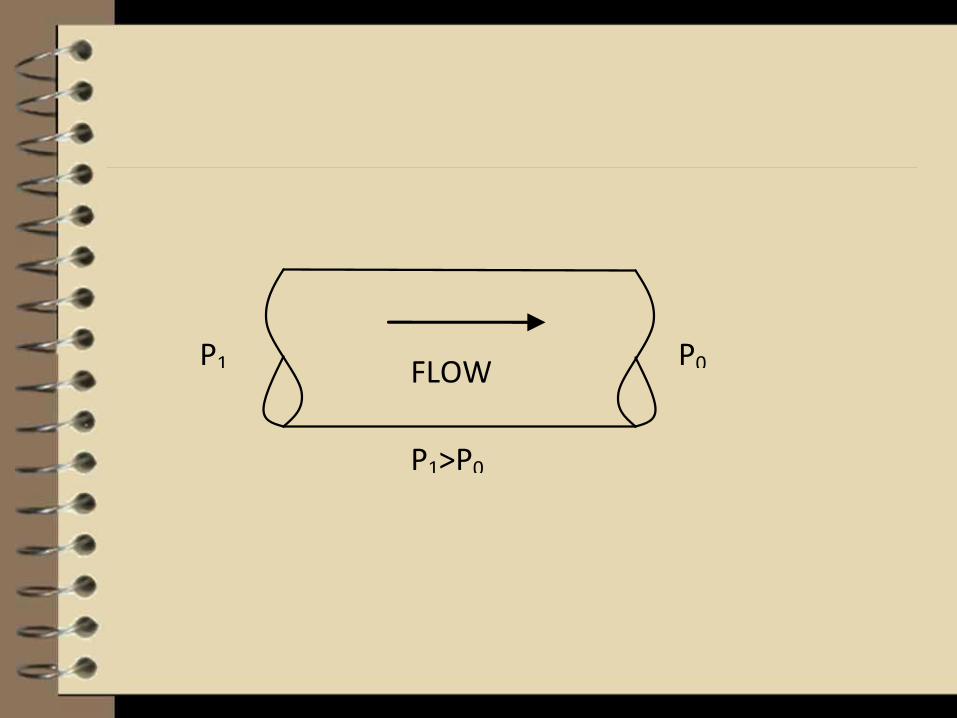
FLOW P0 P1
P1>P0

Duct air moves according to threefundamental
laws of physics:
conservation of mass
conservation of energy
conservation of momentum

Conservation of mass
Conservation of mass simply states that an
air mass is neither created nor destroyed.
From this principle it follows that the
amount of air mass coming into a junction
in a ductwork system is equal to the amount
of air mass leaving the junction
V2 = (V1 * A1)/A2
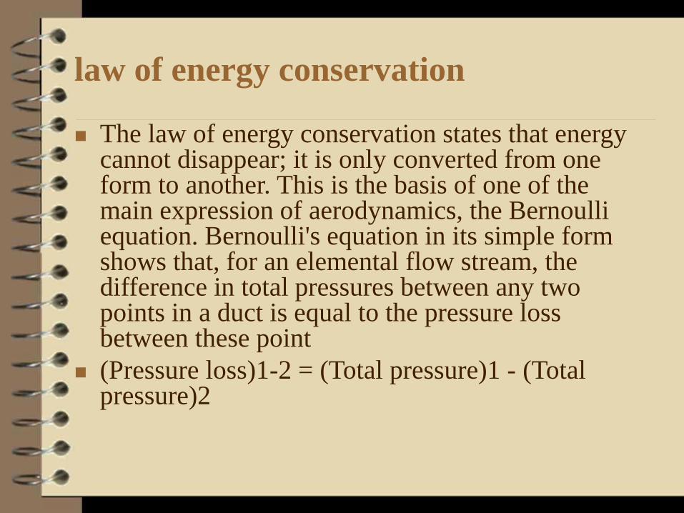
law of energy conservation
The law of energy conservation states that energy cannot disappear; it is only converted from one form to another. This is the basis of one of the main expression of aerodynamics, the Bernoulli equation. Bernoulli's equation in its simple form shows that, for an elemental flow stream, the difference in total pressures between any two points in a duct is equal to the pressure loss between these point
(Pressure loss)1-2 = (Total pressure)1 - (Total pressure)2

Conservation of momentum
Conservation of momentum is based on
Newton's law that a body will maintain its
state of rest or uniform motion unless
compelled by another force to change that
state. This law is useful to explain flow
behavior in a duct system's fitting.

Types of Flow
Laminar Flow
Flow parallel to a boundary layer
Turbulent Flow
Flow which is perpendicular and near the
center of the duct and parallel near the outer
edges of the duct.

Total Pressure, Velocity Pressure, and
Static Pressure
Static pressure
Static pressure is the measure of the potential
energy of a unit of air in the particular cross
section of a duct. Air pressure on the duct wall is
considered static. Imagine a fan blowing into a
completely closed duct; it will create only static
pressure because there is no air flow through the
duct. A balloon blown up with air is a similar case
in which there is only static pressure.

Dynamic (velocity) pressure
Dynamic pressure is the kinetic energy of a
unit of air flow in an air stream. Dynamic
pressure is a function of both air velocity
and density:
Dynamic pressure = (Density) * (Velocity)2
/ 2

Total Pressure
PT = PV + PS
PT = Total Pressure
PV = Velocity Pressure
PS = Static Pressure

Types of Pressure Losses or Resistance to
Flow
Pressure loss in ductwork has three
components
frictional losses along duct walls
dynamic losses in fittings
component losses in duct-mounted
equipment

Component Pressure
Due to physical items with known pressure
drops, such as hoods, filters, louvers or
dampers.

Dynamic Pressure
Dynamic losses are the result of changes in direction and velocity of air flow. Dynamic losses occur whenever an air stream makes turns, diverges, converges, narrows, widens, enters, exits, or passes dampers, gates, orifices, coils, filters, or sound attenuators. .

Velocity profiles are reorganized at these places by the development of vortexes that cause the transformation of mechanical energy into heat
Dynamic loss = (Local loss coefficient) * (Dynamic pressure)
where the Local loss coefficient, known as a C-coefficient, represents flow disturbances for particular fittings

Frictional Pressure
Frictional losses in duct sections are result
from air viscosity and momentum exchange
among particles moving with different
velocities. These losses also contribute
negligible losses or gains in air systems
unless there are extremely long duct runs

Pressure Losses of an Air System
Sections in Series
For sections or components in series simply sum up all the sections. A single duct that has the same shape, cross section, and mass flow is called a duct section or just a section.

Following is the recommended procedure for calculating total pressure loss in a single duct section:
• Gather input data: air flow, duct shape, duct size, roughness, altitude, air temperature, and fittings;
• Calculate air velocity as a function of air flow and cross section;
• Calculate local C-coefficients for each fitting used; and
• Calculate pressure loss using the friction chart


Sections in Parallel
For sections that run parallel, always use the
section with the higher pressure loss/gain to
determine pressure losses/gains through a
system. Adjust the branch with the lower
pressure loss/gain by increasing the flow
rate or decreasing the duct size to increase
the pressure loss to that of the higher branch

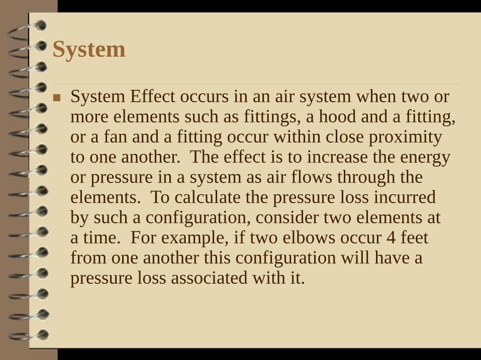
System
System Effect occurs in an air system when two or more elements such as fittings, a hood and a fitting, or a fan and a fitting occur within close proximity to one another. The effect is to increase the energy or pressure in a system as air flows through the elements. To calculate the pressure loss incurred by such a configuration, consider two elements at a time. For example, if two elbows occur 4 feet from one another this configuration will have a pressure loss associated with it.

Fan Performance Specification
Fan total Pressure is the pressure differential
between the inlet and the outlet of the fan.
It can be expressed in these terms:
P t fan = P t loss + P v system outlet + (P s system outlet + P s system entry + P v system entry)
P t fan = Fan Total Pressure
P t loss = Dynamic, Component, and Frictional Pressure through the air system.
P s system outlet = Static Pressure at System Outlet
P s system entry = Static Pressure at System Entry
P v system entry = Velocity Pressure at System Entry
P v system outlet = Velocity Pressure at System Outlet
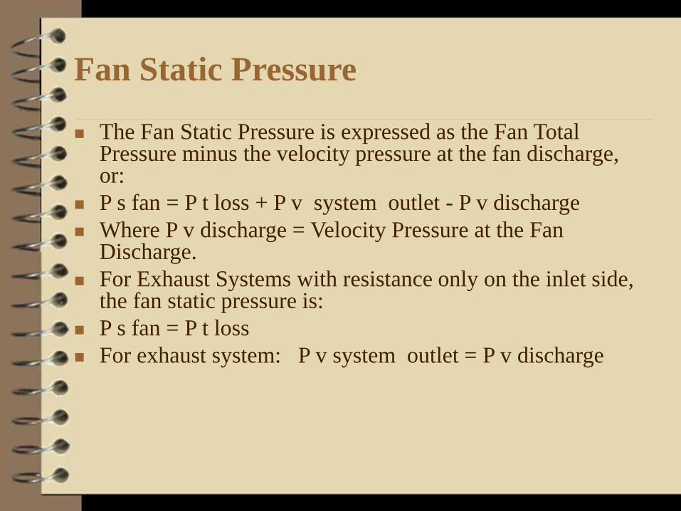
Fan Static Pressure
The Fan Static Pressure is expressed as the Fan Total Pressure minus the velocity pressure at the fan discharge, or:
P s fan = P t loss + P v system outlet - P v discharge
Where P v discharge = Velocity Pressure at the Fan Discharge.
For Exhaust Systems with resistance only on the inlet side, the fan static pressure is:
P s fan = P t loss
For exhaust system: P v system outlet = P v discharge

For Supply Systems with resistance on the outlet side, the fan static pressure is:
P s fan = P t loss - P v discharge
P v system outlet can be assumed to be 0.