Embed Size (px)
Citation preview

http://www.iaeme.com/IJCIET/index.asp 128 [email protected]
International Journal of Civil Engineering and Technology (IJCIET)
Volume 7, Issue 2, March-April 2016, pp. 128–139, Article ID: IJCIET_07_02_010
Available online at
http://www.iaeme.com/IJCIET/issues.asp?JType=IJCIET&VType=7&IType=2
Journal Impact Factor (2016): 9.7820 (Calculated by GISI) www.jifactor.com
ISSN Print: 0976-6308 and ISSN Online: 0976-6316
© IAEME Publication
EXPERIMENTAL STUDY ON SHEAR
BEHAVIOR OF REINFORCED RECYCLED
AGGREGATE CONCRETE BEAMS
Pinal C. Khergamwala
PhD Scholar, I. K. G. Punjab Technical University,
Jalandhar, Punjab, India
Dr. Jagbir Singh
Associate Professor, Department of Civil Engineering, GNDEC,
Ludhiana, India
Dr. Rajesh Kumar
Professor and Head, Department of Civil Engineering,
CCET, Chandigarh, India
ABSTRACT
The use of recycled aggregates (RA) for structural concrete in
construction, to the maximum possible limit, is becoming a necessity more
than a desire. One such mechanical property, shear resistance of recycled
aggregate concrete (RAC) beams is an intensive area of research. Three
parameters i.e. compressive strength, percentage of tension steel and shear
span to depth ratio were considered. An attempt has been made to study shear
strength of RA concrete beams of M 20 grade with 25 and 50 % weight
replacement of natural aggregate (NA) with recycled aggregate (RA) for
different shear span to depth ratios a/d = 1.5, 2.5 and 3.5 with 1 % tension
steel without shear reinforcement and compare the test results with the
available shear models. Seven shear models for comparison were considered
namely ACI 318, Canadian Standard, IS Code, CEB-FIP Model, Zsutty
Equation, Bazant Equation and Okamura and Higai equation. The results
revealed that Shear capacity of a RAC beams with 25 and 50 % RA is
comparable, or sometimes superior, to that of a controlled beam made of
conventional concrete. Equations proposed by Zsutty and Bazant gave
relatively more accurate results in terms of the similar pattern as compared to
other models but still considerably lower values as compared to experimental
results and hence these models can be used effectively for recycled aggregare
concrete also.
Key words: Recycled aggregates, Parameters, Recycled aggregate concrete,
Shear resistance, Shear models, Shear span to depth Ratio (a/d).
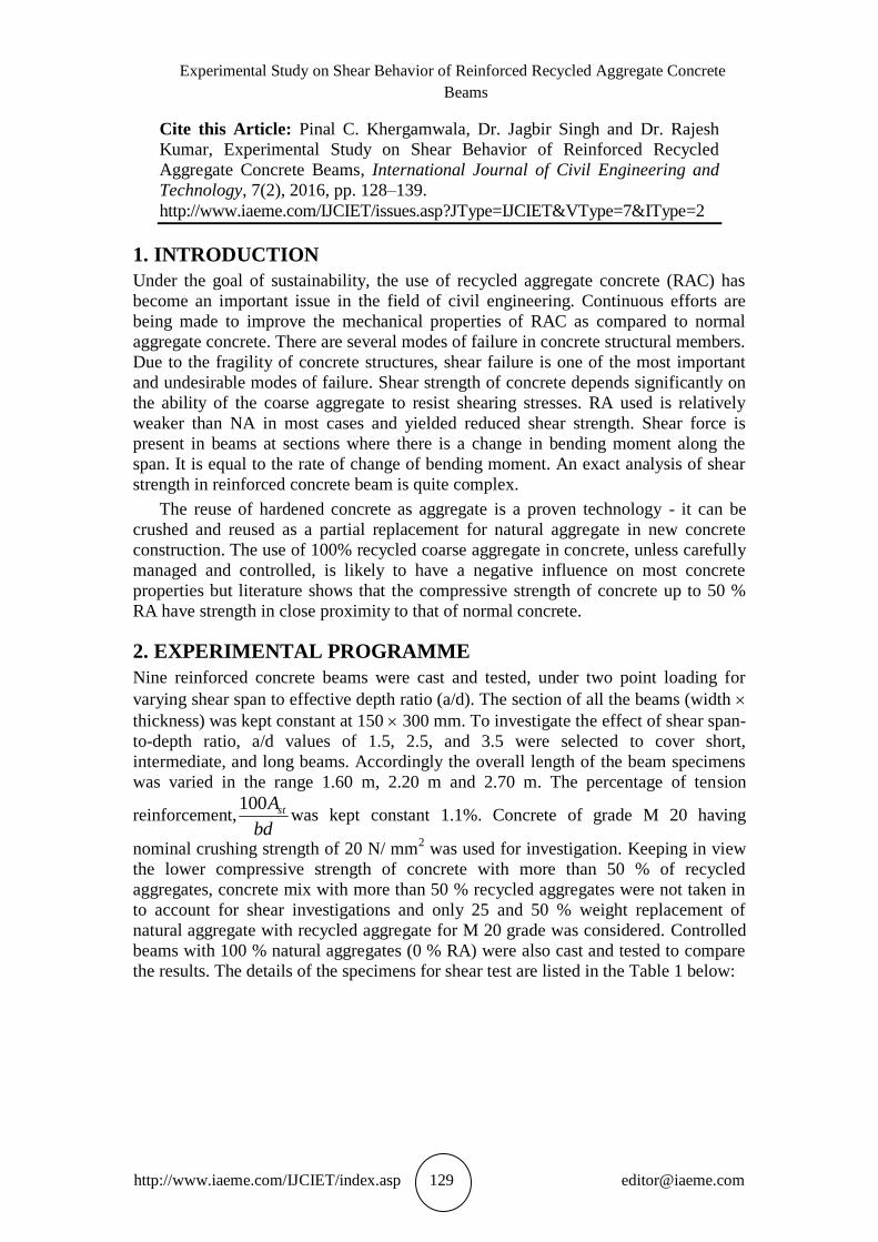
Experimental Study on Shear Behavior of Reinforced Recycled Aggregate Concrete
Beams
http://www.iaeme.com/IJCIET/index.asp 129 [email protected]
Cite this Article: Pinal C. Khergamwala, Dr. Jagbir Singh and Dr. Rajesh
Kumar, Experimental Study on Shear Behavior of Reinforced Recycled
Aggregate Concrete Beams, International Journal of Civil Engineering and
Technology, 7(2), 2016, pp. 128–139.
http://www.iaeme.com/IJCIET/issues.asp?JType=IJCIET&VType=7&IType=2
1. INTRODUCTION
Under the goal of sustainability, the use of recycled aggregate concrete (RAC) has
become an important issue in the field of civil engineering. Continuous efforts are
being made to improve the mechanical properties of RAC as compared to normal
aggregate concrete. There are several modes of failure in concrete structural members.
Due to the fragility of concrete structures, shear failure is one of the most important
and undesirable modes of failure. Shear strength of concrete depends significantly on
the ability of the coarse aggregate to resist shearing stresses. RA used is relatively
weaker than NA in most cases and yielded reduced shear strength. Shear force is
present in beams at sections where there is a change in bending moment along the
span. It is equal to the rate of change of bending moment. An exact analysis of shear
strength in reinforced concrete beam is quite complex.
The reuse of hardened concrete as aggregate is a proven technology - it can be
crushed and reused as a partial replacement for natural aggregate in new concrete
construction. The use of 100% recycled coarse aggregate in concrete, unless carefully
managed and controlled, is likely to have a negative influence on most concrete
properties but literature shows that the compressive strength of concrete up to 50 %
RA have strength in close proximity to that of normal concrete.
2. EXPERIMENTAL PROGRAMME
Nine reinforced concrete beams were cast and tested, under two point loading for
varying shear span to effective depth ratio (a/d). The section of all the beams (width
thickness) was kept constant at 150 300 mm. To investigate the effect of shear span-
to-depth ratio, a/d values of 1.5, 2.5, and 3.5 were selected to cover short,
intermediate, and long beams. Accordingly the overall length of the beam specimens
was varied in the range 1.60 m, 2.20 m and 2.70 m. The percentage of tension
reinforcement,bd
Ast100was kept constant 1.1%. Concrete of grade M 20 having
nominal crushing strength of 20 N/ mm2 was used for investigation. Keeping in view
the lower compressive strength of concrete with more than 50 % of recycled
aggregates, concrete mix with more than 50 % recycled aggregates were not taken in
to account for shear investigations and only 25 and 50 % weight replacement of
natural aggregate with recycled aggregate for M 20 grade was considered. Controlled
beams with 100 % natural aggregates (0 % RA) were also cast and tested to compare
the results. The details of the specimens for shear test are listed in the Table 1 below:
Pinal C. Khergamwala, Dr. Jagbir Singh and Dr. Rajesh Kumar
http://www.iaeme.com/IJCIET/index.asp 130 [email protected]
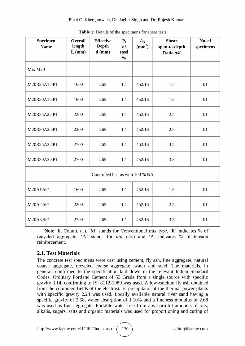
Table 1: Details of the specimens for shear tests
Specimen
Name
Overall
length
L (mm)
Effective
Depth
d (mm)
Pt
of
steel
%
Ast
(mm2)
Shear
span-to-depth
Ratio a/d
No. of
specimens
Mix M20
M20R25A1.5P1 1600 265 1.1 452.16 1.5 01
M20R50A1.5P1 1600 265 1.1 452.16 1.5 01
M20R25A2.5P1 2200 265 1.1 452.16 2.5 01
M20R50A2.5P1 2200 265 1.1 452.16 2.5 01
M20R25A3.5P1 2700 265 1.1 452.16 3.5 01
M20R50A3.5P1 2700 265 1.1 452.16 3.5 01
Controlled beams with 100 % NA
M20A1.5P1 1600 265 1.1 452.16 1.5 01
M20A2.5P1 2200 265 1.1 452.16 2.5 01
M20A3.5P1 2700 265 1.1 452.16 3.5 01
Note: In Colum. (1), ‘M’ stands for Conventional mix type, ‘R’ indicates % of
recycled aggregate, ‘A’ stands for a/d ratio and ‘P’ indicates % of tension
reinforcement.
2.1. Test Materials
The concrete test specimens were cast using cement, fly ash, fine aggregate, natural
coarse aggregate, recycled coarse aggregate, water and steel. The materials, in
general, confirmed to the specification laid down in the relevant Indian Standard
Codes. Ordinary Portland Cement of 53 Grade from a single source with specific
gravity 3.14, confirming to IS: 8112-1989 was used. A low-calcium fly ash obtained
from the combined fields of the electrostatic precipitator of the thermal power plants
with specific gravity 2.24 was used. Locally available natural river sand having a
specific gravity of 2.58, water absorption of 1.10% and a fineness modulus of 2.68
was used as fine aggregate. Portable water free from any harmful amounts of oils,
alkalis, sugars, salts and organic materials was used for proportioning and curing of
Experimental Study on Shear Behavior of Reinforced Recycled Aggregate Concrete
Beams
http://www.iaeme.com/IJCIET/index.asp 131 [email protected]
concrete. Deformed steel bars of 10 mm and 12 mm nominal diameters and with
nominal yield strength of 423 MPa were used as tension reinforcement in the beams.
Shear reinforcement in the form of stirrups were not provided. All the steel
reinforcement bars confirmed to IS 1786: 1985.
Two types of coarse aggregates named Natural Aggregate (NA) and recycled
aggregates (RA) were used in the RAC mixes. Locally available crushed granite
having a specific gravity of 2.70 was used as NA. RA was derived from the tested
concrete cubes in the laboratory that contained well-graded crushed granite stone.
Specific gravity of RA was found 2.48, which is lower than NA. The concrete cubes
were crushed manually to the specified size using a hammer and gradation was
achieved through sieving of RA. The maximum size of coarse aggregate used was 20
mm in both recycled and natural aggregate concrete.
2.2. Concrete Mix Design
The concrete mix M 20 of characteristic strength of 20 N/ mm2 with constant water to
cement ratio (w/c) 0.5 was used in this investigation which is commonly used in
construction of structural members. The mix design was done according to the IS:
10262- 2009 and numerous trial mixes were conducted to obtain the optimum mix.
Once the optimum mix was determined, it was used to produce concrete with 25%
and 50% recycled coarse aggregate by weight replacement of natural coarse
aggregate. Due to the higher water absorption capacity of RA as compared to natural
aggregate, both the aggregates are maintained at saturated surface dry (SSD)
conditions before mixing operations. Fly ash was used as 25% by weight replacement
of cement to achieve proper workability of the mix. The details of optimum mix are
given in Table 2.
Table 2: Mix proportion for optimum mix
Mix Mix
proportion
by weight
Fly
Ash
%
Constituents (kg/m3) W/C
ratio
Cement Fly
Ash
Sand Aggregates
M 20 1:1.5:3.4 25 289 96 578 1310 0.5
2.3. Instrumentation and Testing Procedure
In the present study beams were cast in steel forms with the tension reinforcement
near the bottom. No stirrups (shear reinforcement) were provided in the beams.
Lifting lugs were also provided for transporting the finished specimen to the test
platform. The concrete was compacted with needle vibrator. Form work was removed
after 48 hours. The beams were cured with wet hessian and sand for 28 days. To
facilitate the tracing of cracks, the beams were distempered white prior to testing.
For investigation of the shear behavior, beams designed only for adequate flexural
strength and without any web reinforcement were tested under monotonically
increasing loads in a four point loading configuration to study the shear failure mechanism. The beam specimens were tested as simply supported beam by using a
manually operated hydraulic Jack that applied load gradually on the mid-span of the
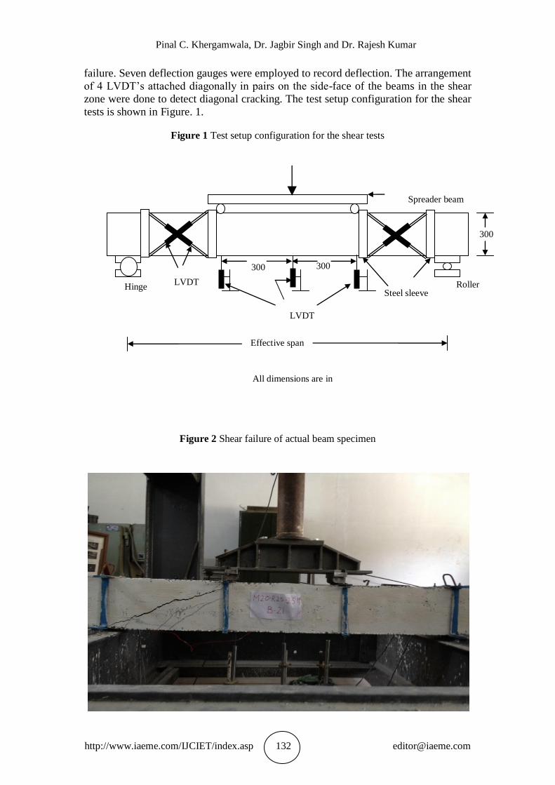
beam specimens until shear failure which pre-empted flexural failure. Diagonal
cracking along with the formation of a dominant inclined crack is indicative of shear
Pinal C. Khergamwala, Dr. Jagbir Singh and Dr. Rajesh Kumar
http://www.iaeme.com/IJCIET/index.asp 132 [email protected]
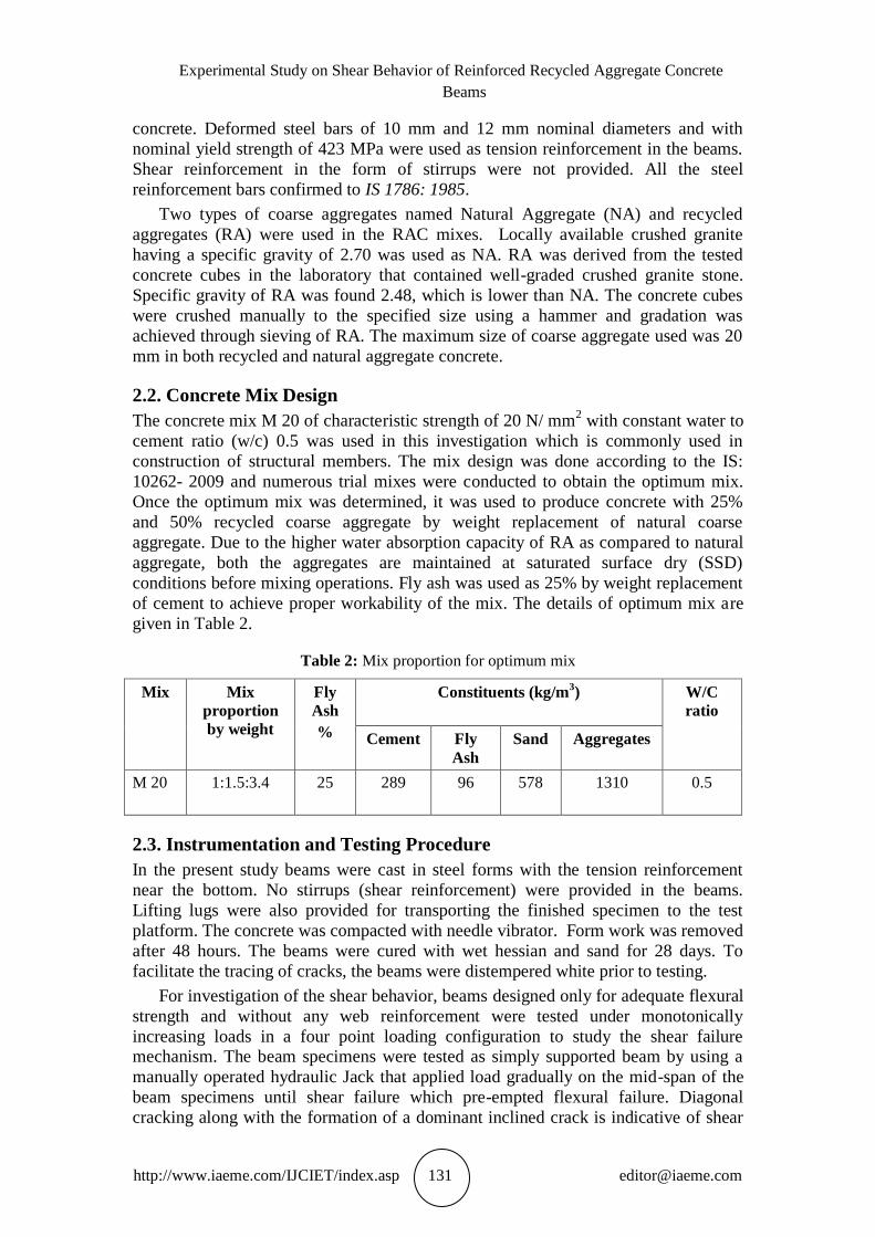
failure. Seven deflection gauges were employed to record deflection. The arrangement
of 4 LVDT’s attached diagonally in pairs on the side-face of the beams in the shear
zone were done to detect diagonal cracking. The test setup configuration for the shear
tests is shown in Figure. 1.
Figure 1 Test setup configuration for the shear tests
Figure 2 Shear failure of actual beam specimen
LVDT
Roller Hinge
Spreader beam
Effective span
All dimensions are in
mm
300 300
300
LVDT
Steel sleeve
Experimental Study on Shear Behavior of Reinforced Recycled Aggregate Concrete
Beams
http://www.iaeme.com/IJCIET/index.asp 133 [email protected]
3. DISCUSSION ON TEST RESULTS
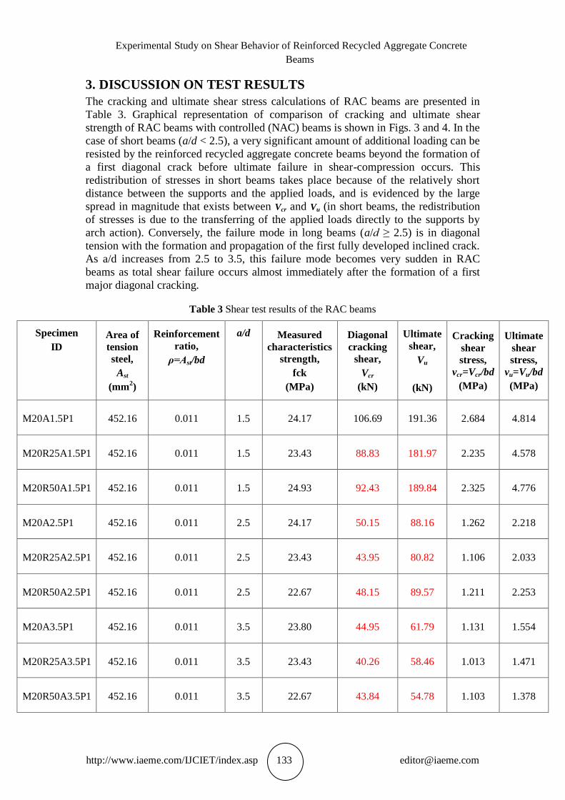
The cracking and ultimate shear stress calculations of RAC beams are presented in
Table 3. Graphical representation of comparison of cracking and ultimate shear
strength of RAC beams with controlled (NAC) beams is shown in Figs. 3 and 4. In the
case of short beams (a/d < 2.5), a very significant amount of additional loading can be
resisted by the reinforced recycled aggregate concrete beams beyond the formation of
a first diagonal crack before ultimate failure in shear-compression occurs. This
redistribution of stresses in short beams takes place because of the relatively short
distance between the supports and the applied loads, and is evidenced by the large
spread in magnitude that exists between Vcr and Vu (in short beams, the redistribution
of stresses is due to the transferring of the applied loads directly to the supports by
arch action). Conversely, the failure mode in long beams (a/d ≥ 2.5) is in diagonal
tension with the formation and propagation of the first fully developed inclined crack.
As a/d increases from 2.5 to 3.5, this failure mode becomes very sudden in RAC
beams as total shear failure occurs almost immediately after the formation of a first
major diagonal cracking.
Table 3 Shear test results of the RAC beams
Specimen
ID
Area of
tension
steel,
Ast
(mm2)
Reinforcement
ratio,
ρ=Ast/bd
a/d
Measured
characteristics
strength,
fck
(MPa)
Diagonal
cracking
shear,
Vcr
(kN)
Ultimate
shear,
Vu
(kN)
Cracking
shear
stress,
vcr=Vcr/bd
(MPa)
Ultimate
shear
stress,
vu=Vu/bd
(MPa)
M20A1.5P1 452.16 0.011 1.5 24.17 106.69 191.36 2.684 4.814
M20R25A1.5P1 452.16 0.011 1.5 23.43 88.83 181.97 2.235 4.578
M20R50A1.5P1 452.16 0.011 1.5 24.93 92.43 189.84 2.325 4.776
M20A2.5P1 452.16 0.011 2.5 24.17 50.15 88.16 1.262 2.218
M20R25A2.5P1 452.16 0.011 2.5 23.43 43.95 80.82 1.106 2.033
M20R50A2.5P1 452.16 0.011 2.5 22.67 48.15 89.57 1.211 2.253
M20A3.5P1 452.16 0.011 3.5 23.80 44.95 61.79 1.131 1.554
M20R25A3.5P1 452.16 0.011 3.5 23.43 40.26 58.46 1.013 1.471
M20R50A3.5P1 452.16 0.011 3.5 22.67 43.84 54.78 1.103 1.378
Pinal C. Khergamwala, Dr. Jagbir Singh and Dr. Rajesh Kumar
http://www.iaeme.com/IJCIET/index.asp 134 [email protected]
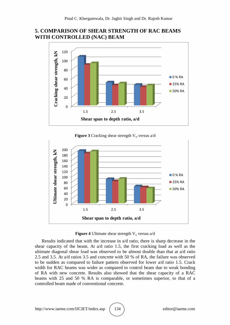
5. COMPARISON OF SHEAR STRENGTH OF RAC BEAMS
WITH CONTROLLED (NAC) BEAM
Figure 3 Cracking shear strength Vcr versus a/d
Figure 4 Ultimate shear strength Vu versus a/d
Results indicated that with the increase in a/d ratio, there is sharp decrease in the
shear capacity of the beam. At a/d ratio 1.5, the first cracking load as well as the
ultimate diagonal shear load was observed to be almost double than that at a/d ratio
2.5 and 3.5. At a/d ratios 3.5 and concrete with 50 % of RA, the failure was observed
to be sudden as compared to failure pattern observed for lower a/d ratio 1.5. Crack
width for RAC beams was wider as compared to control beam due to weak bonding
of RA with new concrete. Results also showed that the shear capacity of a RAC
beams with 25 and 50 % RA is comparable, or sometimes superior, to that of a
controlled beam made of conventional concrete.
0
20
40
60
80
100
120
1.5 2.5 3.5
Crack
ing s
hear
stre
ngth
, k
N
Shear span to depth ratio, a/d
0 % RA
25% RA
50% RA
0
20
40
60
80
100
120
140
160
180
200
1.5 2.5 3.5
Ult
imate
sh
ear
stre
ngth
, k
N
Shear span to depth ratio, a/d
0 % RA
25% RA
50% RA
Experimental Study on Shear Behavior of Reinforced Recycled Aggregate Concrete
Beams
http://www.iaeme.com/IJCIET/index.asp 135 [email protected]
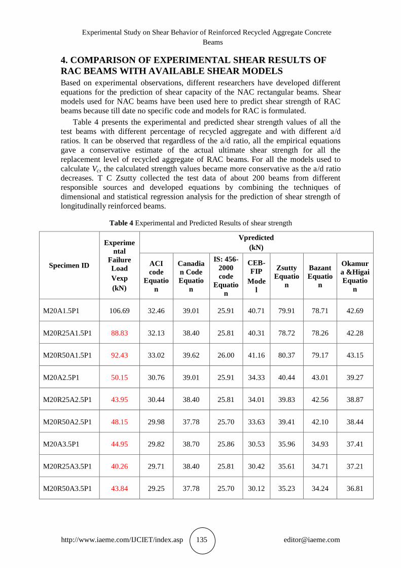
4. COMPARISON OF EXPERIMENTAL SHEAR RESULTS OF
RAC BEAMS WITH AVAILABLE SHEAR MODELS
Based on experimental observations, different researchers have developed different
equations for the prediction of shear capacity of the NAC rectangular beams. Shear
models used for NAC beams have been used here to predict shear strength of RAC
beams because till date no specific code and models for RAC is formulated.
Table 4 presents the experimental and predicted shear strength values of all the
test beams with different percentage of recycled aggregate and with different a/d
ratios. It can be observed that regardless of the a/d ratio, all the empirical equations
gave a conservative estimate of the actual ultimate shear strength for all the
replacement level of recycled aggregate of RAC beams. For all the models used to
calculate Vc, the calculated strength values became more conservative as the a/d ratio
decreases. T C Zsutty collected the test data of about 200 beams from different
responsible sources and developed equations by combining the techniques of
dimensional and statistical regression analysis for the prediction of shear strength of
longitudinally reinforced beams.
Table 4 Experimental and Predicted Results of shear strength
Specimen ID
Experime
ntal
Failure
Load
Vexp
(kN)
Vpredicted
(kN)
ACI
code
Equatio
n
Canadia
n Code
Equatio
n
IS: 456-
2000
code
Equatio
n
CEB-
FIP
Mode
l
Zsutty
Equatio
n
Bazant
Equatio
n
Okamur
a &Higai
Equatio
n
M20A1.5P1 106.69 32.46 39.01 25.91 40.71 79.91 78.71 42.69
M20R25A1.5P1 88.83 32.13 38.40 25.81 40.31 78.72 78.26 42.28
M20R50A1.5P1 92.43 33.02 39.62 26.00 41.16 80.37 79.17 43.15
M20A2.5P1 50.15 30.76 39.01 25.91 34.33 40.44 43.01 39.27
M20R25A2.5P1 43.95 30.44 38.40 25.81 34.01 39.83 42.56 38.87
M20R50A2.5P1 48.15 29.98 37.78 25.70 33.63 39.41 42.10 38.44
M20A3.5P1 44.95 29.82 38.70 25.86 30.53 35.96 34.93 37.41
M20R25A3.5P1 40.26 29.71 38.40 25.81 30.42 35.61 34.71 37.21
M20R50A3.5P1 43.84 29.25 37.78 25.70 30.12 35.23 34.24 36.81
Pinal C. Khergamwala, Dr. Jagbir Singh and Dr. Rajesh Kumar
http://www.iaeme.com/IJCIET/index.asp 136 [email protected]
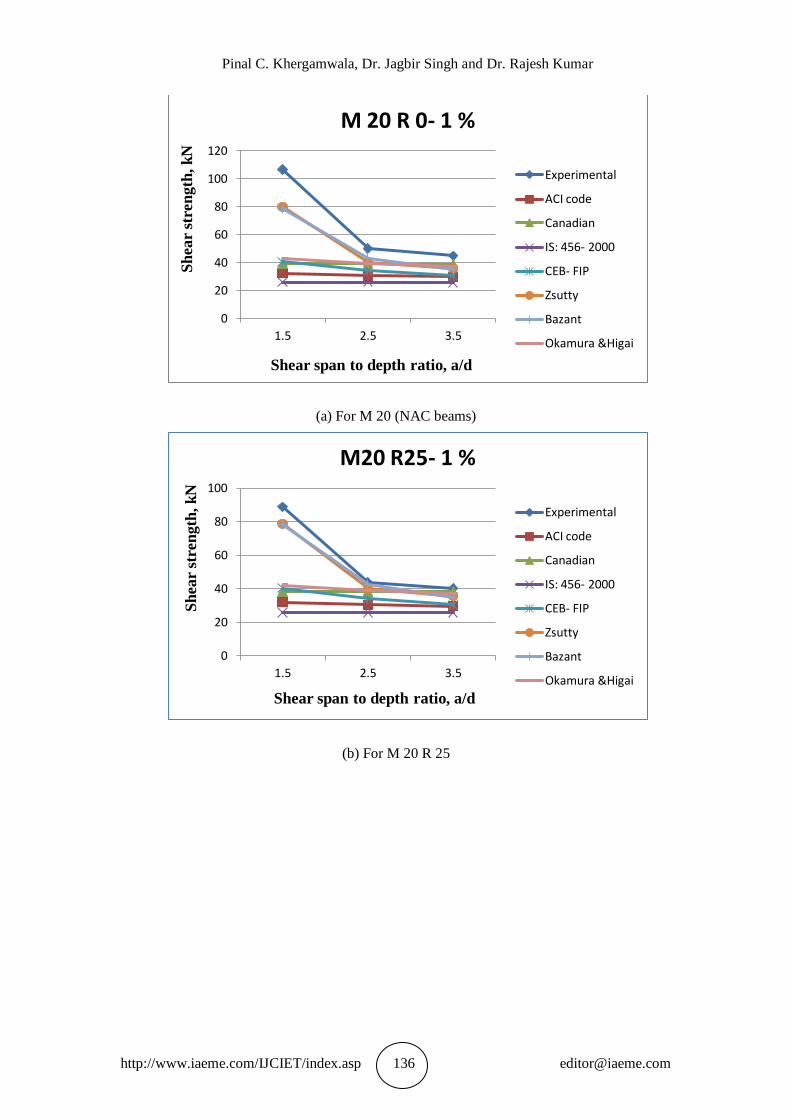
(a) For M 20 (NAC beams)
(b) For M 20 R 25
0
20
40
60
80
100
120
1.5 2.5 3.5
Sh
ear
stre
ngth
, k
N
Shear span to depth ratio, a/d
M 20 R 0- 1 %
Experimental
ACI code
Canadian
IS: 456- 2000
CEB- FIP
Zsutty
Bazant
Okamura &Higai
0
20
40
60
80
100
1.5 2.5 3.5
Sh
ear
stre
ngth
, k
N
Shear span to depth ratio, a/d
M20 R25- 1 %
Experimental
ACI code
Canadian
IS: 456- 2000
CEB- FIP
Zsutty
Bazant
Okamura &Higai
Experimental Study on Shear Behavior of Reinforced Recycled Aggregate Concrete
Beams
http://www.iaeme.com/IJCIET/index.asp 137 [email protected]
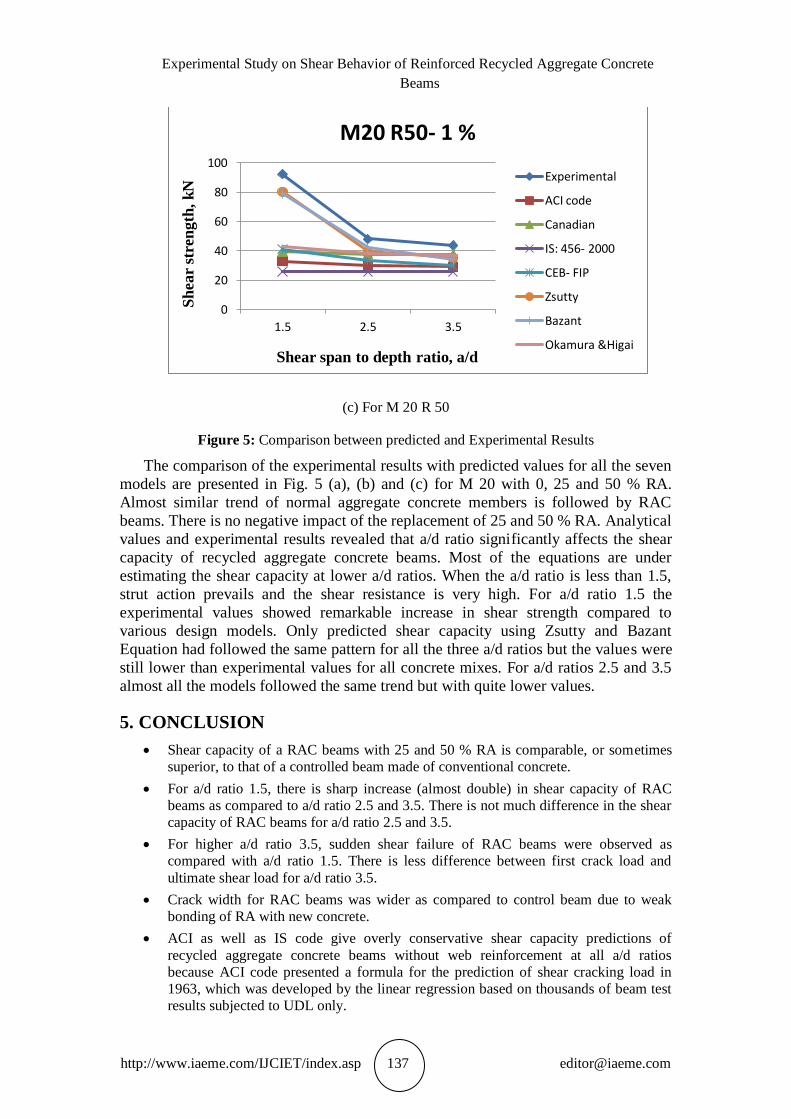
(c) For M 20 R 50
Figure 5: Comparison between predicted and Experimental Results
The comparison of the experimental results with predicted values for all the seven
models are presented in Fig. 5 (a), (b) and (c) for M 20 with 0, 25 and 50 % RA.
Almost similar trend of normal aggregate concrete members is followed by RAC
beams. There is no negative impact of the replacement of 25 and 50 % RA. Analytical
values and experimental results revealed that a/d ratio significantly affects the shear
capacity of recycled aggregate concrete beams. Most of the equations are under
estimating the shear capacity at lower a/d ratios. When the a/d ratio is less than 1.5,
strut action prevails and the shear resistance is very high. For a/d ratio 1.5 the
experimental values showed remarkable increase in shear strength compared to
various design models. Only predicted shear capacity using Zsutty and Bazant
Equation had followed the same pattern for all the three a/d ratios but the values were
still lower than experimental values for all concrete mixes. For a/d ratios 2.5 and 3.5
almost all the models followed the same trend but with quite lower values.
5. CONCLUSION
Shear capacity of a RAC beams with 25 and 50 % RA is comparable, or sometimes
superior, to that of a controlled beam made of conventional concrete.
For a/d ratio 1.5, there is sharp increase (almost double) in shear capacity of RAC
beams as compared to a/d ratio 2.5 and 3.5. There is not much difference in the shear
capacity of RAC beams for a/d ratio 2.5 and 3.5.
For higher a/d ratio 3.5, sudden shear failure of RAC beams were observed as
compared with a/d ratio 1.5. There is less difference between first crack load and
ultimate shear load for a/d ratio 3.5.
Crack width for RAC beams was wider as compared to control beam due to weak
bonding of RA with new concrete.
ACI as well as IS code give overly conservative shear capacity predictions of
recycled aggregate concrete beams without web reinforcement at all a/d ratios
because ACI code presented a formula for the prediction of shear cracking load in
1963, which was developed by the linear regression based on thousands of beam test
results subjected to UDL only.
0
20
40
60
80
100
1.5 2.5 3.5
Sh
ear
stre
ngth
, k
N
Shear span to depth ratio, a/d
M20 R50- 1 %
Experimental
ACI code
Canadian
IS: 456- 2000
CEB- FIP
Zsutty
Bazant
Okamura &Higai
Pinal C. Khergamwala, Dr. Jagbir Singh and Dr. Rajesh Kumar
http://www.iaeme.com/IJCIET/index.asp 138 [email protected]
The Canadian code considered only compressive strength of concrete. It has not taken
into account the effect of shear span to depth ratio and longitudinal tension
reinforcement on shear strength of beams. The shear resistance of RAC member
predicted based on Canadian code underestimates the actual shear capacity of
member at all a/d ratios.
Shear capacity of the RAC members predicted based on CEB-FIP model and
Okamura- Higai equation showed conservative values at all a/d ratios.
Zsutty equation is more appropriate and simple to predict the shear strength of both
shorter and long beams as it takes into account size effect and longitudinal steel effect
for RAC beams also.
The Bazant equation has better agreement with the test data. In this equation five
parameters (fc΄, ρ, a,d, d and da) are correlated with ultimate shear strength of
rectangular beams, especially the effect of aggregate size, which plays very important
role in the shear strength.
ACKNOWLEDGMENTS
I express my sincere thanks to I. K. G. Punjab Technical University, Kapurthala,
India for providing strong platform for pursuing Ph.D. Authors acknowledge the
help received from Head and faculty members of the Civil Engineering Department,
Guru Nanak Dev Engineering College, Ludhiana, Punjab, for making testing
facilities available to them. The invaluable cooperation of the laboratory staff of
Heavy Testing Laboratory and Concrete Testing Laboratory of Civil Engineering
Department is gratefully acknowledged.
REFERENCES
[1] ACI 318-02, Building code requirements for reinforced concrete, (ACI 318-02)
and commentary, (ACI 318R-02). Detroit: American Concrete Institute, 2002.
[2] Angelakos D, Bentz E C and Collins M P,” Effect of concrete strength and
minimum stirrups on strength of large members”, ACI Structural Journal; 2001,
98, 290–300.
[3] Brito J D and Richardo R,” Recycled aggregate concrete methodology for
estimating its long term properties”, Indian journal of engineering and material
sciences, 2010, volume 17, 449- 462.
[4] Etxeberria M, Marí AR, Vázquez E, “Recycled aggregate concrete as structural
material.” Mater Struct; 2007, 40:529–41.
[5] Fathifazl G, Razaqpur A G, Burkan Isgor O and Abbas A, “Shear capacity
evaluation of steel reinforced recycled concrete (RRC) beams”, Engineering
Structures journal, 2011, volume 33, 1025–1033.
[6] González F, Martínez A and Eiras L, “Structural shear behavior of recycled
concrete with silica fume”, Construction and Building Materials journal, 2009,
volume 23, 3406–3410.
[7] Han B C, Yun H D and Chung SY, ” Shear capacity of reinforced concrete
beams made with recycled-aggregate”, ACI Special Publication SP 200-31,
Farmington Hills, MI, USA: American Concrete Institute; 2001, 503-515.
[8] Hansen TC, Narud H. “Strength of recycled concrete made from crushed
concrete coarse aggregate,” Concrete International, 1983, No. 1, 579-83.
[9] I. Gull, “Testing of strength of recycled waste concrete and its applicability,”
Journal of Construction Engineering and Management, 2011, vol. 137, 1–5.
Experimental Study on Shear Behavior of Reinforced Recycled Aggregate Concrete
Beams
http://www.iaeme.com/IJCIET/index.asp 139 [email protected]
[10] Imran A. Bukhari and Saeed Ahmed, “Evaluation of Shear Strength of High
Strength Concrete Beams without Stirrups.” The Arabian Journal for Science and
Engineering, 2008, Volume 33, Number 2B, .323- 335.
[11] IS: 10262-2009 Concrete mix Proportioning – Guidelines (First Revision).
Bureau of Indian Standards, New Delhi.
[12] IS: 383-1970 Specification for coarse and fine aggregates from natural sources
for concrete (Second Revision)
[13] IS: 456-2000 Plain and reinforced concrete–code of practice (Fourth Revision)
[14] Khaldoun R, “Mechanical properties of concrete with recycled coarse aggregate”,
Building and Environment journal, 2007, volume 42, 407–415.
[15] Kishore R, (1994) “Some Studies on Recycled Aggregate Concrete,” PhD Thesis,
1994, IIT Bombay, India.
[16] Kou Shicong, “Reusing recycled aggregates in structural concrete”, Ph. D thesis,
2006, The Hong Kong polytechnic university.
[17] Kumar Roy BN, Sai ASR, ” Brick basalt and recycled aggregate concrete,”
Indian
[18] Malhotra VM, “Recycled concrete - A new aggregate,” Canadian Journal of Civil
Engineering, 1978, 542-52.
[19] Nixon PJ, “Recycled Concrete as an Aggregate for Concrete-A Review,” First
State of the Art Report, RILEM TC-37-DRC, Materials and Structures: Research
and Testing (RILEM), 1978, Vol. 11, No. 65, 371-378.
[20] Pinal C. Khergamwala, Dr. Jagbir Singh and Dr. Rajesh Kumar, “Effect of
Recycled Coarse Aggregates on Characteristic Strength of Different Grades of
Concrete,” International Journal of Civil Engineering & Technology (IJCIET),
2014, Volume. 4, Issue. 6, 186-192.
[21] Ramammurthy K and Gumaste K S, “Properties of recycled aggregate concrete,”
Indian Concrete Journal, 1998, volume 72, N1, 49-53.
[22] Ravindrarajah RS, Tam CT. “Properties of concrete made with crushed concrete
as coarse aggregate,” Magazine of Concrete Research, 1985, No. 130, 3729-38.
[23] Salem Ahmed Abukersh, “High quality recycled aggregate concrete”, Ph. D
thesis, 2009, School of Engineering and the Built environment, Edinburgh
Napier University, UK.
[24] Sami W T and Akmal S A, “Influence of recycled concrete aggregates on strength
properties of concrete”, Construction and Building Materials journal, 2009,
volume 23, 1163–1167.
[25] T.C. Nwofor, S. Sule, D.B. Eme, A Comparative Study of Bs8110 and
Eurocode 2 Standards For Design of A Continuous Reinforced Concrete
Beam, International Journal of Civil Engineering and Technology, 6(5),
2015, pp. 76–84.
[26] Prerna Nautiyal, Saurabh Singh and Geeta Batham, A comparative study
of the effect of infill walls on seismic performance of reinforced concrete
buildings, International Journal of Civil Engineering and Technology,
4(4), 2013, pp. 208–218.
[27] Singh S K and Sharma P C, “Use of recycled aggregates in concrete- A Paradigm
Shift”, National building materials journal, 2007.
[28] Zsutty, T. C, “Shear Strength Predictions for Separate Categories of Simple Beam
Tests”, ACI Journal Proceedings, 1971, 68(2), 138–143.