Embed Size (px)
Citation preview
Construction and Building Materials 204 (2019) 809–827
Contents lists available at ScienceDirect
Construction and Building Materials
journal homepage: www.elsevier .com/locate /conbui ldmat
Shear behaviour of concrete beams with recycled aggregateand steel fibres
https://doi.org/10.1016/j.conbuildmat.2019.01.1300950-0618/� 2019 Elsevier Ltd. All rights reserved.
Abbreviations: F, fibres; RA, recycled aggregate; S, stirrup; Vr, total ultimate shear strength; Vc, ultimate shear strength of concrete; Vs, ultimate shear strengthreinforcement; Vp, shear strength provided by the component in the applied shear direction of the pre-stressing force factored by up; uc, strength factor of conspecified compressive strength of concrete; TR, transverse reinforcement; bw, beam web width or circular section diameter or wall thickness; dv, effective shearfactor to consider in low-density concrete; b, factor considering cracked concrete’s shear strength; Av, area of shear reinforcement; fy, specified yield strengthprestressed reinforcement or anchor steel; h, angle of diagonal compressive stresses to the longitudinal axis of the member; S, transverse reinforcement spacinpredicted value of shear strength; VR.c, shear strength attributed to concrete; VR.s, shear strength provided by stirrup; VR.max, maximum permitted shear strengthlever arm; ex, ongitudinal strain at beam’s mid-depth; Es, reinforcement steel modulus of elasticity; dg, maximum aggregate size; fst, transverse reinforcement yield stlongitudinal reinforcement ratio; Vu, ultimate shear force; Mu, ultimate bending moment; LWC, lightweight concrete; JCI, Japan Concrete Institute; NWC, normaconcrete; SFSCC, steel fibres self-compacting concrete; RAC, recycled aggregate concrete; NAC, natural aggregate concrete.⇑ Corresponding author.
E-mail addresses: [email protected] (H.R. Chaboki), [email protected] (M. Ghalehnovi), [email protected] (A. Karimipour), [email protected] (J. [email protected] (M. Khatibinia).
Hamid Reza Chaboki a, Mansour Ghalehnovi b,⇑, Arash Karimipour b, Jorge de Brito c, Mohsen Khatibinia a
aDepartment of Civil Engineering at Ferdowsi University of Mashhad, Mashhad, IranbDepartment of Civil Engineering at University of Birjand, Birjand, IrancCERIS, Department of Civil Engineering, Architecture and Georresources, Instituto Superior Técnico, Universidade de Lisboa, Portugal
h i g h l i g h t s
� Effect of steel fibres and recycled aggregate content on the shear behaviour of reinforced concrete beams.� Development of a mixing process considering the particular characteristics of RA.� The densified form of SF appears to exhibit a different behaviour compared to its original (dispersed) condition.� It is feasible to produce HPC without incorporating natural aggregates (NA).� Lack of appropriate formula to predict the behaviour of steel fibres recycled aggregate concrete beams.� Steel fibres can partially compensate the lack of transverse reinforcement in terms of shear behaviour.
a r t i c l e i n f o
Article history:Received 28 September 2018Received in revised form 2 January 2019Accepted 22 January 2019
Keywords:BeamsSteel fibresRecycled coarse aggregateShear behaviourReinforced concrete
a b s t r a c t
This paper mainly studies the shear characteristics of reinforced concrete beams manufactured by intro-ducing coarse recycled aggregate (RA) and steel fibres. For that purpose, 27 concrete beams (15 cm, 20 cmand 150 cm of width, height and length, respectively) with dissimilar spacing of transverse reinforcement(TR) were produced. Additionally, the RA obtained from building demolition waste and introduced in theconcrete mixes at 0%, 50% and 100%. Furthermore, the steel fibres (SF) were introduced in the beams at0%, 1% and 2% to improve the flexural characteristics. Specimens underwent a 4 points bending test. Inthis test, the maximum deflection, shear capacity, at the mid-span of the beam and tension strain wereobtained. The determination of the influence of SF and TR spacing and SF on RA reinforced concretebeams was the aim of this investigation. In addition, the results of this experiment and the requirementsshown in the standards (e.g. CEB-fib model code, ACI and CSA) were compared. The results show that thatSF improved the specimens’ maximum strain and their use enhanced the shear behaviour of RA concretebeams relative to control specimens.
� 2019 Elsevier Ltd. All rights reserved.
of shearcrete; f0c ,depth; k,of non-
g; VR.pred,; z, innerress; qw,l weight
e Brito),
810 H.R. Chaboki et al. / Construction and Building Materials 204 (2019) 809–827
1. Introduction
Recycling aggregates (RA) is a way of changing a waste productinto a resource. Therefore, using demolition materials instead ofnatural materials could be an efficient method to keep the environ-ment safer. RA has been used in structural concrete elements andlow demand applications e.g. back-fills and lower layers of roads[1]. However, the use of RA remains limited to 1% of structural con-crete applications [2].
RA can replace natural aggregate (NA) at 100% in structural con-crete. Many experimental studies have been reported on theshear characteristics of recycled aggregate concrete beams (RACB)[3–13]. In all studies, the replacement content of NA with RA, com-pressive strength, transverse and longitudinal reinforcement ratio,and cross-section dimensions were considered. All samples under-went 4 points flexural loading. The influence of transverse rein-forcement (TR) spacing and steel fibres (SF) was less investigatedand more studies were done on concrete beams without TR[4–6,8,7,11–13]. Previous studies showed that there are no signifi-cant differences in terms of cracking loading, load–deflection rela-tionship and failure mode between beams manufactured withrecycled and NA. Initial cracking and stiffness were also investi-gated without paying attention to shear strength (VR)-) and theinfluence of SF [5,13]. RA concrete’s VR is a little lower than thatof NA concrete and this difference increases by increasing the RAcontent [12]. Most of the studies present VR prediction equationsfor NA concrete beams [5,11,13], and others predict VR for 100%RA beams [12,14].
According to these studies, there is no distinct difference in VR
between natural and RA reinforced concrete beams with TR. Thestandards’ formulas are not suitable for RA concrete beams withoutTR [4,6,8]. Wastes can replace cement, aggregate or be used as addi-tions. Several investigations have been focused on using RA [2–9].They showed that the quality of the RA is generally lower than thatof the NA due to remaining mortar particles, micro cracking, andhigher water absorption and porosity of the RA. Therefore, usingRA has an unfavourable effect on mechanical properties, durability,and workability of concrete [10–12]. The negative influence of RA onthe concrete beams’ shear behaviour was also studied [11].
In 2018, Pradhan et al. [15] studied the shear behaviour of recy-cled aggregate concrete (RAC) beams. The shear failure was brittleand sudden. Therefore, this failure can be dangerous if it is notproperly designed for. 14 specimens were manufactured andtested for this purpose. In each specimen, the effect of TR was con-sidered in order to investigate its shear behaviour. So, six speci-mens were selected with no TR to evaluate the contribution ofRAC to shear strength mechanisms and in eight specimens TRwas considered. The inferior mechanical properties of the RACare improved satisfactorily by implementing the Particle PackingMethod in the mix design along with the established Two-StageMixing Approach. According to the obtained outcomes, the ulti-mate shear strength decreased by around 14% in RAC beams withno TR. Therefore, according to these results, the best formula waspresented to determine the ultimate shear strength of RAC beamswith and without TR.
In another study, the improvement in shear performance ofrecycled coarse aggregates RC beams was investigated by Etmanet al. [16]. For this purpose, a total of 11 RC simply supportedRAC beams and one conventional concrete beam were tested.The specimens were subjected to a four-point bending test. RAwas used at three replacement content: 15%, 30% and 45% (in termof volume). The shear span-to-depth ratio was 1, 2 and 3. Two cur-ing methods for the RAC beams were implemented using cementslurry and a Styrene Butadiene Rubber (SBR) compound to improvetheir shear behaviour. The obtained results showed that the shear
strength was reduced by 8%, 14% and 19% for replacement contentof RA 15%, 30% and 45%, respectively.
In 2018, Rahal and Alrefaei [17] studied the shear strength ofRAC beams with TR. 18 RC beams were manufactured and tested.The contents of RA, NA and TR were the variables in this study.RA were used at three volume contents (0%, 20% and 100%). Theratio of the longitudinal reinforcement in all the beams was1.38%. The experimental outcomes showed that the shear strengthdid not significantly reduce by using RA, but RA significantly affectsthe cracks pattern.
Ignjatovic et al. [18] investigated the shear performance of RACbeams focusing on the TR content. Nine simply supported beamswere manufactured and tested in a four-point bending test. Load-ing was performed until complete failure. RA were incorporated inthe concrete mixes at 0%, 50% and 100%. Furthermore, three TRratios were considered (0%, 0.14% and 0.19%). According to the out-comes, it was found that the shear behaviour and the shearstrength of the specimens manufactured with 50% and 100% ofRA were very similar to those that were manufactured with NA.
SF are effective materials to control cracks’ propagation. There-fore, using them leads to reduce cracks’ width in concrete mem-bers. [19,20]. Additionally, high SF contents increase the tensilestrength (fctm) of concrete members by increasing the bondbetween the various materials of concrete members [21]. On theother hand, if insufficient steel fibre contents are used, the fctm isnot significantly improved. [22]. In 2008, Kim et al. [23] studiedthe behaviour of FRC beams with four kinds of fibres and two SFcontents (0.4% and 1.2%) surrounded by a supposedly identicalmortar matrix with 56 MPa compressive strength. Four fibres typeswere high strength steel twisted, high strength steel hooked, highmolecular weight polyethylene spectra, and PVA-fibres. Tests wereperformed according to ASTM standards. The high strength steeltwisted fibre specimens showed the best performance in almostall behaviour features, including bearing capacity, energy dissipa-tion and multiple cracking behaviours, while the PVA-fibre speci-mens showed the worst performance in all aspects of theresponse. According to the obtained outcomes, it was shown thathigh strength steel twisted fibres perform significantly better thanother SF in a higher strength matrix.
Therefore, many studies assessed the effect of fibres’ propertieson the shear and flexural strength and toughness of FRC. Altun andAktas [24] assessed the effect of fibres on the flexural performanceof lightweight concrete (LWC) beams. LWC has a lower modulus ofelasticity. Therefore, cracks propagate faster in RC members man-ufactured using LWC than in normal and high-strength concrete.However, SF are used as an additive material in concrete in orderto increase the energy dissipation and control cracks propagation.Therefore, SF were added to the LWC and their effects on the flex-ural performance of concrete and RC beams investigated. For thispurpose, LWC and RC specimens were manufactured by using dif-ferent fibres contents. The specimens were subjected to four-pointbending tests. As a result of this study, it was found that SF increasethe toughness capacity of prismatic concrete beams and their duc-tility. This also increases the strength capacity and ductility of theRC beams. Through this research, the performance of the RC beamswas shown to increase by adding SF.
In 2015, Yoo et al. [25] investigated the post-cracking behaviourof normal and high-strength SFC beams. In this research, speci-mens were manufactured and tested according to the Japan Con-crete Institute (JCI) standard. The suggested models wereconfirmed through a comparison of the previous flexural test out-comes. The compressive strength and elastic modulus showed neg-ligible changes with the inclusion of SF, while the strain capacityand post-peak behaviour were improved by adding SF. Further-more, the flexural strength, post-peak ductility and deflection
H.R. Chaboki et al. / Construction and Building Materials 204 (2019) 809–827 811
capacity significantly increased by using 1% SF content. Finally, thefracture energy increased by increasing the SF content anddecreasing the concrete strength.
In another study, Mertol et al. [26] considered the effect offibres contents on the flexural performance of RC beams. In thisstudy, 20 specimens with a cross-section width of 180 mm andheight of 250 mm, a length of 3500 mm and different SF contentswere manufactured and tested. 10 different longitudinal reinforce-ment ratios (with a minimum of 0.2% and a maximum of 2.5%)were also used. Load-deflection relationship was achieved and cal-culated in terms of ultimate bearing capacity, ultimate displace-ment, service stiffness, post-peak stiffness, shear and flexuraltoughness. For over-reinforced designed specimens, the post-peak stiffness of the SFC specimens is expressively lower than thatof normal weight concrete (NWC) specimens. Experimental load–deflection relationships were also compared to those obtainedfrom the strain compatibility theory and best fit stress-strain rela-tionships of SFC in tension and compression were determined.
Patil and Single [27] tested the SFC beams under predominanttorsion and bending. Using SF in NWC leads to improving themechanical properties of the RC structure. The main aim of thisstudy was the effect of SF on the torsional and shear strength per-formance of NWC beams. Therefore, the torsional strength andcombination of torsional-shear-bending strength were investi-gated. The obtained outcomes show an improvement in torsionalstrength, combined torsional-shear-bending strength and crackstrength of concrete by using of SF. A modified coefficient of theexperimental formula was suggested to calculate the torsionalstrength and stress of SFC.
In 2017, Luccioni et al. [28] studied the static and dynamic per-formance of SFRC beams. The outcomes of static classification testscarried out on slabs and the obtained outcomes of blast tests onslabs were analysed. Improvements were found in static bendingresponse with different fibres contents compared to those con-ducted under dynamic loading.
In 2018, Lee et al. [29] determined the structural response ofSFC beams under different loading rates. In this study, the speci-mens were conducted under static, impact, and blast loading.According to this study, using SF enhances the ductility of RCbeams regardless of the strain rate. Furthermore, the SF contribu-tion to shear strength was evaluated under various loading type.The obtained outcomes showed that the static shear strength ofSFC beams effectively improved.
In another study, Mahmod et al. [30] considered steel fibresself-compacting concrete (SFSCC) as new material that can flowbeneath its own weight in the fresh state, thus removing any needfor vibration and difficulties related with the formwork, but havingthe benefits of SF addition in the hardened state. In this research,the effect of SF on the splitting tensile strength, compressivestrength, and modulus of elasticity was studied. For this aim, 14RC beams were manufactured and tested under monotonic load.The obtained outcomes showed that the flexural strengthincreased by increasing the SF content.
CSA-A23 [31] presents equations to predict the reinforced con-crete beams’ shear strength ðVrÞ, as follows:
Vr ¼ Vc þ Vs þ Vp ð1Þ
where Vr , Vc , Vs and Vp are a total ultimate shear strength, ultimateshear strength of concrete, the ultimate shear strength of shearreinforcement and component in the applied shear’s direction ofthe effective pre-stressing force factored by up; for variable depthmembers, the component of the effective pre-stressing force andthe components of flexural, tension and compression in the appliedshear’s direction, positive when resisting the applied shear, factored
by up, are summed. Furthermore, Vr shall not surpass the nextequation:
Vr:max ¼ 0:25ucf0cbwdv þ Vp ð2Þ
where uc , f0c , bw and dv are the concrete’s strength factor, concrete’s
specified compressive strength, beam web width or diameter of thecircular section or wall thickness, and effective shear depth, takenas the greater of 0.9 d (effective depth) or 0.72 h (height), respec-tively. Nevertheless, the value of Vc needed to be computed usingthe next formula:
Vc ¼ uckbffiffiffiffif0c
qbwdv ð3Þ
where k and b are factors to consider for low-density concrete andcracked concrete’s shear strength, respectively. In the determina-tion of Vc , the term have to be higher than eight MPa. For membershaving TR perpendicular to the longitudinal axis, Vs shall be com-puted in accordance with the following formula:
Vs ¼ucAv f ydv cot h
Sð4Þ
where Av , h; f y and S are the area of shear reinforcement, the angleof the diagonal compressive stresses to the longitudinal axis of themember, the specified yield strength of non-pre-stressed reinforce-ment or anchor steel, and spacing of TR, respectively. Also, shearreinforcement’s ðAvÞ minimum area can be evaluated as follows:
Av ¼ 0:06ffiffiffiffif0c
qbwsf y
ð5Þ
According to CEB-fib [32], for beams without stirrups and forbeams with stirrups, the shear strength can be obtained as follows:
VR:pred ¼VR:c þ VR:s forVR:c þ VR:s < VR:max
max VR:c;VR:cð Þ � VR:max forVR:c þ VR:s � VR:max
�ð6Þ
where VR:pred, VR:c , VR:s and VR:max are the predicted value of VR (N), VR
attributed to concrete (N), VR given by stirrups (N) and maximumpermitted VR (N), respectively. The VR represented in Eq. (6) wascalculated in accordance with the following equations:
VR:c ¼ kvffiffiffiffif c
qzbw ð7Þ
VR:s ¼ Asw
Szf yw cot h ð8Þ
VR:max ¼ kegfcf czbwsinhcosh ð9Þwhere z, bw, Asw and S are the inner lever arm = 0.9 d (mm), cross-section width or web width (mm), TR area ðmm2Þ and spacing ofTR (mm), respectively. Moreover, the other factors are shown bythe following equations:
kdg ¼ 3216þ dg
� 0:75 ð10Þ
kv ¼¼ 0:4
1þ1500ex � 13001000þkdgz
if qw ¼ 0
¼ 0:41þ1500ex � ð1� Ve:test
VR: max:pred� 0 if qw � 0:08
ffiffiffiffif c
p=f yw
8<: ð11Þ
h ¼ 200 þ 10000ex ð12Þ
ex ¼VE:test
d2
ad � 1� �þ 1
� �2EsAsl
ð13Þ
e1 ¼ ex þ ðex þ 0:002Þcot2h ð14Þ
812 H.R. Chaboki et al. / Construction and Building Materials 204 (2019) 809–827
ke ¼ 11:2þ 55e1
� 0:65 ð15Þ
gfc ¼30f c
� 1=3
� 1:0 ð16Þ
where ex, Es and dg are the longitudinal strain at mid-depth of beam(mm/mm), modulus of elasticity (N/mm2) of reinforcement steeland maximum aggregate size (mm), respectively.
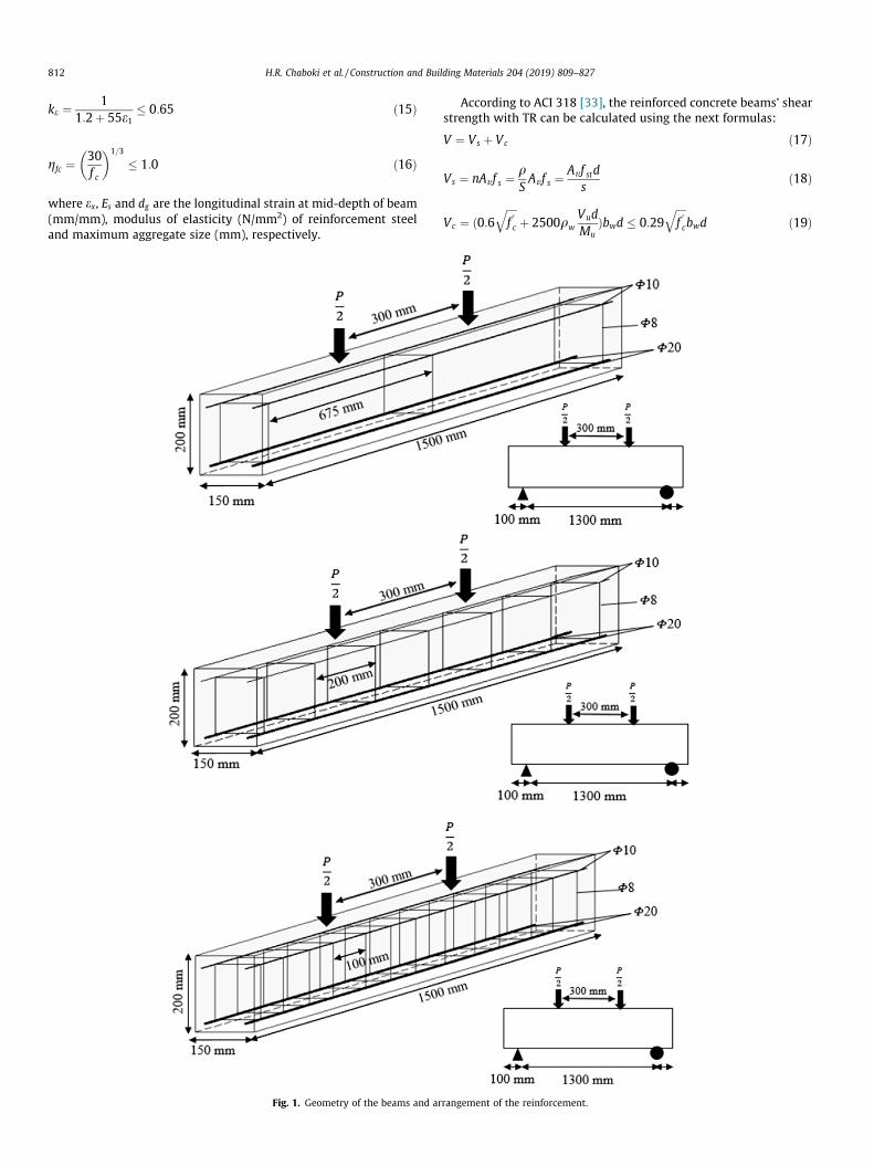
Fig. 1. Geometry of the beams and ar
According to ACI 318 [33], the reinforced concrete beams’ shearstrength with TR can be calculated using the next formulas:
V ¼ Vs þ Vc ð17Þ
Vs ¼ nAv f s ¼qSAv f s ¼
Av f stds
ð18Þ
Vc ¼ ð0:6ffiffiffiffif0c
qþ 2500qw
VudMu
Þbwd � 0:29ffiffiffiffif0c
qbwd ð19Þ
rangement of the reinforcement.
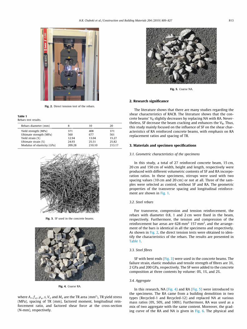
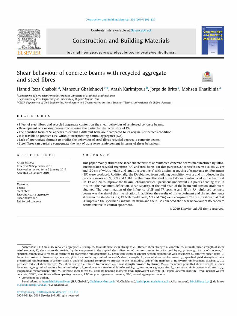
Fig. 2. Direct tension test of the rebars.
Table 1Rebars test results.
Rebars diameter (mm) 8 10 20
Yield strength (MPa) 371 408 371Ultimate strength (MPa) 560 677 561Yield strain (%) 12.94 13.04 15.27Ultimate strain (%) 24.93 25.51 25.82Modulus of elasticity (GPa) 209.28 210.10 213.17
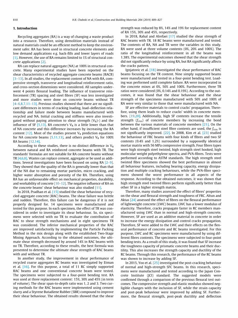
Fig. 3. SF used in the concrete beams.
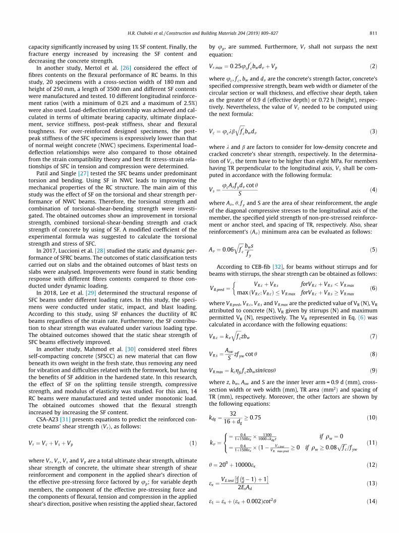
Fig. 4. Coarse RA.
Fig. 5. Coarse NA.
H.R. Chaboki et al. / Construction and Building Materials 204 (2019) 809–827 813
where Av , f st , qw; s, Vu and Mu are the TR area ðmm2Þ, TR yield stress(MPa), spacing of TR (mm), factored moment, longitudinal rein-forcement ratio, and factored shear force at the cross-section(N-mm), respectively.
2. Research significance
The literature shows that there are many studies regarding theshear characteristics of RACB. The literature shows that the con-crete beams’ VR slightly decreases by replacing NA with RA. Never-theless, SF decrease the beam cracking and enhances the VR. Thus,this study mainly focused on the influence of SF on the shear char-acteristics of RA reinforced concrete beams, with emphasis on RAreplacement ratios and spacing of TR.
3. Materials and specimen specifications
3.1. Geometric characteristics of the specimens
In this study, a total of 27 reinforced concrete beam, 15 cm,20 cm and 150 cm of width, height and length, respectively wereproduced with different volumetric contents of SF and RA incorpo-ration ratios. In these specimens, stirrups were used with twospacing values (10 cm and 20 cm) or not at all. Three of the sam-ples were selected as control, without SF and RA. The geometricproperties of the transverse spacing and longitudinal reinforce-ment are shown in Fig. 1.
3.2. Steel rebars
For transverse, compression and tension reinforcement, therebars with diameter 0.8, 1 and 2 cm were fixed in the beam,respectively. Furthermore, the tension and compression of thereinforcement bar areas are 628 mm2 157 mm2, and the arrange-ment of the bars is identical in all the specimens and respectively.As shown in Fig. 2, the direct tension tests were obtained to iden-tify the characteristics of the rebars. The results are presented inTable 1.
3.3. Steel fibres
SF with bent ends (Fig. 3) were used in the concrete beams. Thefailure strain, elastic modulus and tensile strength of fibres are 3%,2 GPa and 200 GPa, respectively. The SF were added to the concretecomposition at three contents by volume: 0%, 1%, and 2%.
3.4. Aggregate
In this research, NA (Fig. 4) and RA (Fig. 5) were introduced tothe specimens. The RA came from a building demolition in twotypes (Recycled-1 and Recycled-12) and replaced NA at variousmass ratios (0%, 50%, and 100%). Furthermore, RA was used as amix of two aggregate with the same content. Moreover, the grad-ing curve of the RA and NA is given in Fig. 6. The physical and
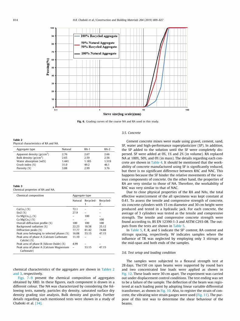
Fig. 6. Grading curves of the coarse NA and RA used in this study.
Table 2Physical characteristics of RA and NA.
Aggregate type Natural RA-1 RA-2
Apparent density (gr/cm3) 2.76 2.67 2.66Bulk density (gr/cm3) 2.65 2.59 2.56Water absorption (wt%) 1.441 1.185 1.519Crush index (%) 31.0 49.2 46.1Porosity (%) 3.88 2.99 3.76
Table 3Chemical properties of RA and NA.
Chemical composition Aggregate type
Natural Recycled-1
Recycled-2
Ca(Co3) (%) 72.1 – –Sio2 (%) 27.9 – –Ca Mg(Co3)2 (%) – 100 –Ca Mg(Co3) (%) – – 100Overall diffraction profile (%) 100 100 100Background radiation (%) 22.23 18.58 25.12Diffraction peaks (%) 77.77 81.42 74.88Peak area belonging to selected phases (%) 16.08 53.15 47.15Peak area of phase A (Calcium Carbonate
Calcite) (%)11.10 – –
Peak area of phase B (Silicon Oxide) (%) 4.99 – –Peak area of phase A (Calcium Magnesium
Carbonate)– 53.15 47.15
814 H.R. Chaboki et al. / Construction and Building Materials 204 (2019) 809–827
chemical characteristics of the aggregates are shown in Tables 2and 3, respectively.
Figs. 7–9 present the chemical composition of aggregatesobtained by XRD. In these figures, each component is drawn in adifferent colour. The NA was characterized by considering the fol-lowing tests, namely, particles dry density, saturated surface drydensity grading size analysis, Bulk density and gravity. Furtherdetails regarding each mentioned tests were shown in a study ofChaboki et al. [34].
3.5. Concrete
Cement concrete mixes were made using gravel, cement, sand,SF, water and high-performance superplasticizer (SP). In addition,the SP added to the solution until the SF were completely dis-persed. SF were added at 0%, 1% and 2% (in volume). RA replacedNA at 100%, 50%, and 0% (in mass). The details regarding each con-crete are shown in Table 4. It should be mentioned that the work-ability of concrete manufactured using SF is significantly reduced,but there is no significant difference between RAC and NAC. Thishappens because the SF hinder the relative movements of the var-ious components of concrete. On the other hand, the properties ofRA are very similar to those of NA. Therefore, the workability ofRAC was very similar to that of NAC.
Due to close physical properties of the RA and NAs, the totaleffective water/cement of the all specimens was kept constant at0.41. To assess the tensile and compressive strength of concrete,six concrete cylinders with 15 cm diameter and 30 cm height wereproduced and tested in a hydraulic jack. For each concrete, theaverage of 3 cylinders was tested as the tensile and compressivestrength. The tensile and compressive concrete strength werefound according to, BS EN 12390:1-3 and ASTM C293-08. The out-puts from the tests are shown in Table 5.
In Table 5, F, R, and S indicate the SF’ content, RA content andstirrups spacing, respectively. W indicates samples where theinfluence of TR was neglected by employing only 3 stirrups atthe mid-span and both ends of the samples.
3.6. Test setup and loading condition
The samples were subjected to a flexural strength test at28 days. The150 cm span beams were supported by round barsand two concentrated line loads were applied as shown inFig. 12. These loads were 30 cm apart. The experiment was carriedout under displacement control conditions. The test ending was setto be a failure of the sample. The deflection of the beam was regis-tered at each loading point by adopting linear variable differentialtransformer, as shown in Fig. 10. Also, to register the strain of con-crete, the vibrating wire strain gauges were used (Fig. 11). The pur-pose of this test was to determine the shear behaviour of thebeams.
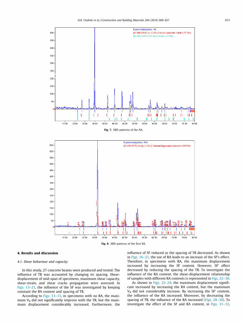
Fig. 7. XRD patterns of the NA.
Fig. 8. XRD patterns of the first RA.
H.R. Chaboki et al. / Construction and Building Materials 204 (2019) 809–827 815
4. Results and discussion
4.1. Shear behaviour and capacity
In this study, 27 concrete beams were produced and tested. Theinfluence of TR was accounted by changing its spacing. Shear-displacement of mid-span of specimens, maximum shear capacity,shear-strain, and shear cracks propagation were assessed. InFigs. 13–21, the influence of the SF was investigated by keepingconstant the RA content and spacing of TR.
According to Figs. 13–15, in specimens with no RA, the maxi-mum VR did not significantly improve with the TR, but the maxi-mum displacement considerably increased. Furthermore, the
influence of SF reduced as the spacing of TR decreased. As shownin Figs. 16–21, the use of RA leads to an increase of the SF’s effect.Therefore, in specimens with RA, the maximum displacementincreased by increasing the SF content. However, SF’ effectdecreased by reducing the spacing of the TR. To investigate theinfluence of the RA content, the shear-displacement relationshipof samples with different RA contents is represented in Figs. 22–30.
As shown in Figs. 22–24, the maximum displacement signifi-cant increased by increasing the RA content, but the maximumVR did not considerably increase. By increasing the SF’ content,the influence of the RA increased. Moreover, by decreasing thespacing of TR, the influence of the RA increased (Figs. 28–30). Toinvestigate the effect of the SF and RA content, in Figs. 31–33,
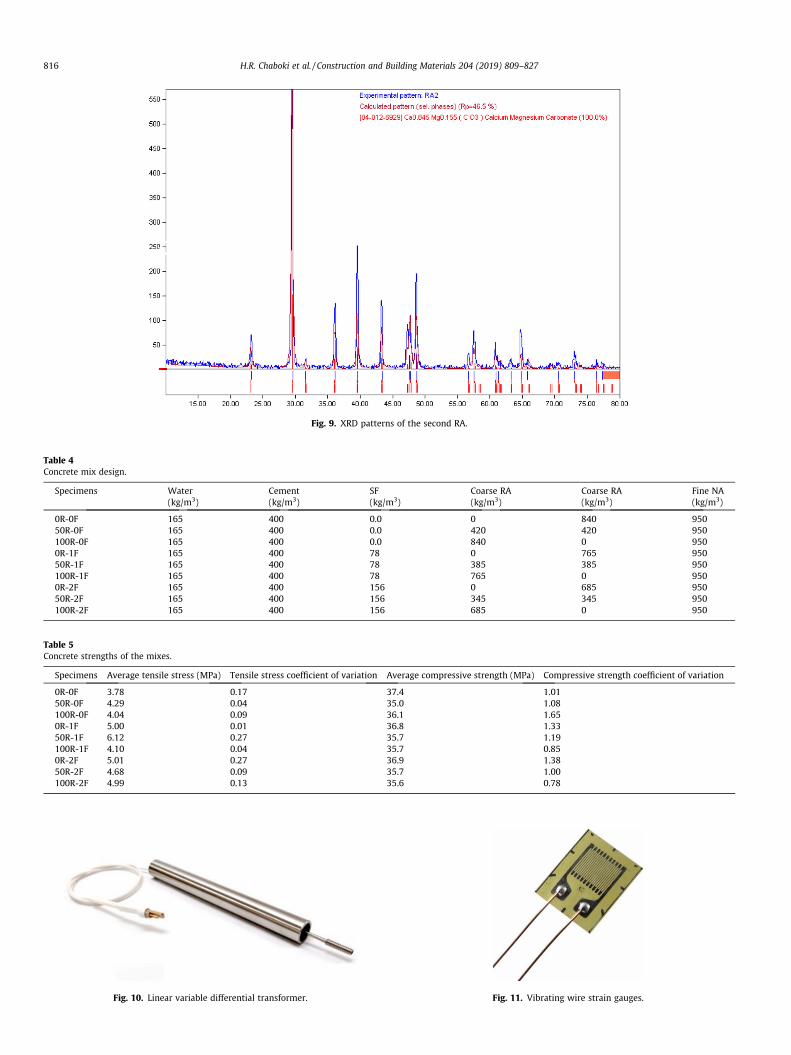
Fig. 9. XRD patterns of the second RA.
Table 4Concrete mix design.
Specimens Water(kg/m3)
Cement(kg/m3)
SF(kg/m3)
Coarse RA(kg/m3)
Coarse RA(kg/m3)
Fine NA(kg/m3)
0R-0F 165 400 0.0 0 840 95050R-0F 165 400 0.0 420 420 950100R-0F 165 400 0.0 840 0 9500R-1F 165 400 78 0 765 95050R-1F 165 400 78 385 385 950100R-1F 165 400 78 765 0 9500R-2F 165 400 156 0 685 95050R-2F 165 400 156 345 345 950100R-2F 165 400 156 685 0 950
Table 5Concrete strengths of the mixes.
Specimens Average tensile stress (MPa) Tensile stress coefficient of variation Average compressive strength (MPa) Compressive strength coefficient of variation
0R-0F 3.78 0.17 37.4 1.0150R-0F 4.29 0.04 35.0 1.08100R-0F 4.04 0.09 36.1 1.650R-1F 5.00 0.01 36.8 1.3350R-1F 6.12 0.27 35.7 1.19100R-1F 4.10 0.04 35.7 0.850R-2F 5.01 0.27 36.9 1.3850R-2F 4.68 0.09 35.7 1.00100R-2F 4.99 0.13 35.6 0.78
Fig. 10. Linear variable differential transformer. Fig. 11. Vibrating wire strain gauges.
816 H.R. Chaboki et al. / Construction and Building Materials 204 (2019) 809–827
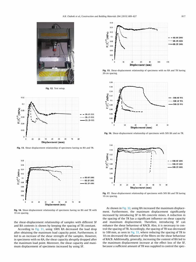
Fig. 12. Test setup.
Fig. 13. Shear-displacement relationship of specimens having no RA and TR.
Fig. 14. Shear-displacement relationship of specimens having no RA and TR with10 cm spacing.
Fig. 15. Shear-displacement relationship of specimens with no RA and TR having20 cm spacing.
Fig. 16. Shear-displacement relationship of specimens with 50% RA and no TR.
Fig. 17. Shear-displacement relationship of specimens with 50% RA and TR having10 cm spacing.
H.R. Chaboki et al. / Construction and Building Materials 204 (2019) 809–827 817
the shear-displacement relationship of samples with different SFand RA contents is shown by keeping the spacing of TR constant.
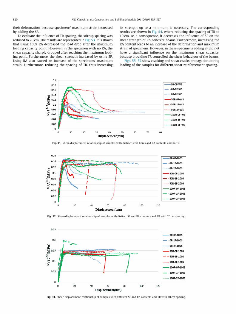
According to Fig. 31, using 100% RA decreased the load dropafter obtaining the maximum load capacity point. Furthermore, itled to an increase of the shear strength of the samples. However,in specimens with no RA, the shear capacity abruptly dropped afterthe maximum load point. Moreover, the shear capacity and maxi-mum displacement of specimens increased by using SF.
As shown in Fig. 32, using RA increased the maximum displace-ment. Furthermore, the maximum displacement significantlyincreased by introducing SF to RA concrete mixes. A reduction inthe spacing of the TR has a significant influence on shear capacityand maximum displacement. Therefore, introducing SF canenhance the shear behaviour of RACB. Also, it is necessary to con-trol the spacing of TR. Accordingly, the spacing of TR was decreasedto 100 mm, as seen in Fig. 33, where reducing the spacing of TR to10 cm decreased the influence of the fibres on the shear behaviourof RACB. Additionally, generally, increasing the content of RA led tothe maximum displacement increase at the effect loss of the SF,because a sufficient amount of TR was supplied to control the spec-
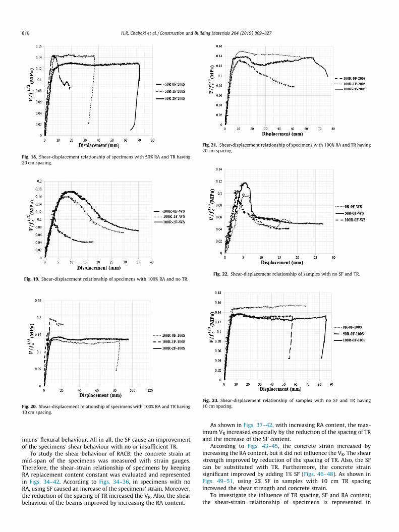
Fig. 18. Shear-displacement relationship of specimens with 50% RA and TR having20 cm spacing.
Fig. 19. Shear-displacement relationship of specimens with 100% RA and no TR.
Fig. 20. Shear-displacement relationship of specimens with 100% RA and TR having10 cm spacing.
Fig. 21. Shear-displacement relationship of specimens with 100% RA and TR having20 cm spacing.
Fig. 22. Shear-displacement relationship of samples with no SF and TR.
Fig. 23. Shear-displacement relationship of samples with no SF and TR having10 cm spacing.
818 H.R. Chaboki et al. / Construction and Building Materials 204 (2019) 809–827
imens’ flexural behaviour. All in all, the SF cause an improvementof the specimens’ shear behaviour with no or insufficient TR.
To study the shear behaviour of RACB, the concrete strain atmid-span of the specimens was measured with strain gauges.Therefore, the shear-strain relationship of specimens by keepingRA replacement content constant was evaluated and representedin Figs. 34–42. According to Figs. 34–36, in specimens with noRA, using SF caused an increase of the specimens’ strain. Moreover,the reduction of the spacing of TR increased the VR. Also, the shearbehaviour of the beams improved by increasing the RA content.
As shown in Figs. 37–42, with increasing RA content, the max-imum VR increased especially by the reduction of the spacing of TRand the increase of the SF content.
According to Figs. 43–45, the concrete strain increased byincreasing the RA content, but it did not influence the VR. The shearstrength improved by reduction of the spacing of TR. Also, the SFcan be substituted with TR. Furthermore, the concrete strainsignificant improved by adding 1% SF (Figs. 46–48). As shown inFigs. 49–51, using 2% SF in samples with 10 cm TR spacingincreased the shear strength and concrete strain.
To investigate the influence of TR spacing, SF and RA content,the shear-strain relationship of specimens is represented in
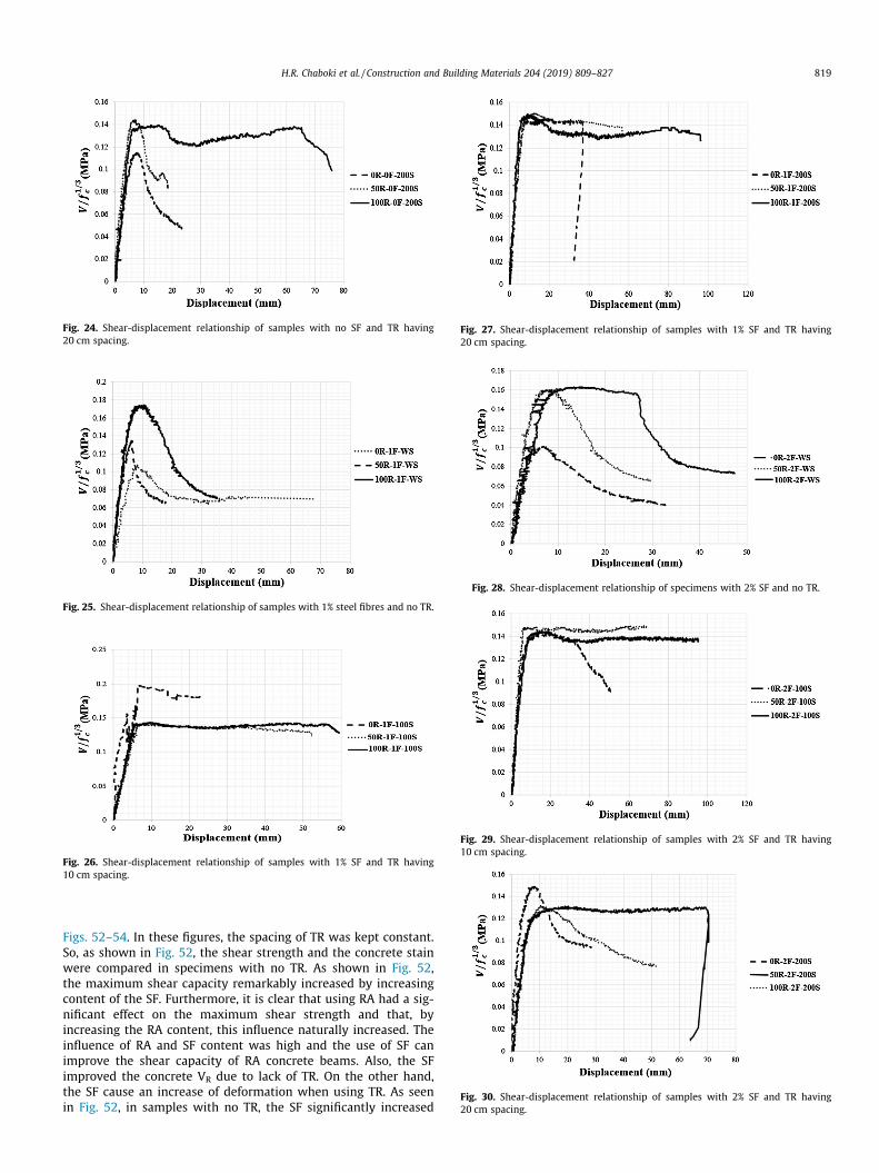
Fig. 24. Shear-displacement relationship of samples with no SF and TR having20 cm spacing.
Fig. 25. Shear-displacement relationship of samples with 1% steel fibres and no TR.
Fig. 26. Shear-displacement relationship of samples with 1% SF and TR having10 cm spacing.
Fig. 27. Shear-displacement relationship of samples with 1% SF and TR having20 cm spacing.
Fig. 28. Shear-displacement relationship of specimens with 2% SF and no TR.
Fig. 29. Shear-displacement relationship of samples with 2% SF and TR having10 cm spacing.
Fig. 30. Shear-displacement relationship of samples with 2% SF and TR having20 cm spacing.
H.R. Chaboki et al. / Construction and Building Materials 204 (2019) 809–827 819
Figs. 52–54. In these figures, the spacing of TR was kept constant.So, as shown in Fig. 52, the shear strength and the concrete stainwere compared in specimens with no TR. As shown in Fig. 52,the maximum shear capacity remarkably increased by increasingcontent of the SF. Furthermore, it is clear that using RA had a sig-nificant effect on the maximum shear strength and that, byincreasing the RA content, this influence naturally increased. Theinfluence of RA and SF content was high and the use of SF canimprove the shear capacity of RA concrete beams. Also, the SFimproved the concrete VR due to lack of TR. On the other hand,the SF cause an increase of deformation when using TR. As seenin Fig. 52, in samples with no TR, the SF significantly increased
820 H.R. Chaboki et al. / Construction and Building Materials 204 (2019) 809–827
their deformation, because specimens’ maximum strain increasedby adding the SF.
To evaluate the influence of TR spacing, the stirrup spacing wasreduced to 20 cm. The results are represented in Fig. 53. It is shownthat using 100% RA decreased the load drop after the maximumloading capacity point. However, in the specimen with no RA, theshear capacity sharply dropped after reaching the maximum load-ing point. Furthermore, the shear strength increased by using SF.Using RA also caused an increase of the specimens’ maximumstrain. Furthermore, reducing the spacing of TR, thus increasing
Fig. 31. Shear-displacement relationship of samples wi
Fig. 32. Shear-displacement relationship of samples with d
Fig. 33. Shear-displacement relationship of samples with di
its strength up to a minimum, is necessary. The correspondingresults are shown in Fig. 54, where reducing the spacing of TR to10 cm. As a consequence, it decreases the influence of SF on theshear strength of RA concrete beams. Furthermore, increasing theRA content leads to an increase of the deformation and maximumstrain of specimens. However, in these specimens adding SF did nothave a significant influence on the maximum shear capacity,because providing TR controlled the shear behaviour of the beams.
Figs. 55–57 show cracking and shear cracks propagation duringloading of the samples for different shear reinforcement spacing.
th distinct steel fibres and RA contents and no TR.
istinct SF and RA contents and TR with 20 cm spacing.
fferent SF and RA contents and TR with 10 cm spacing.
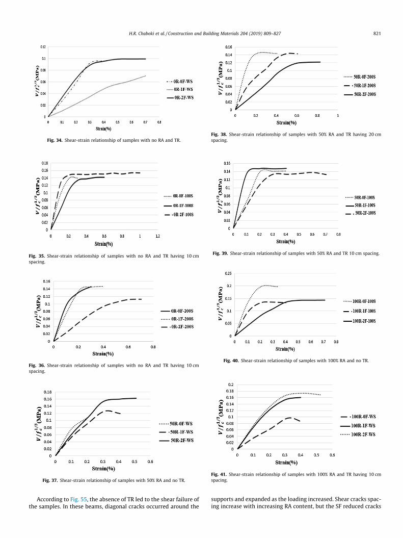
Fig. 36. Shear-strain relationship of samples with no RA and TR having 10 cmspacing.
Fig. 37. Shear-strain relationship of samples with 50% RA and no TR.
Fig. 38. Shear-strain relationship of samples with 50% RA and TR having 20 cmspacing.
Fig. 39. Shear-strain relationship of samples with 50% RA and TR 10 cm spacing.
Fig. 40. Shear-strain relationship of samples with 100% RA and no TR.
Fig. 41. Shear-strain relationship of samples with 100% RA and TR having 10 cmspacing.
Fig. 34. Shear-strain relationship of samples with no RA and TR.
Fig. 35. Shear-strain relationship of samples with no RA and TR having 10 cmspacing.
H.R. Chaboki et al. / Construction and Building Materials 204 (2019) 809–827 821
According to Fig. 55, the absence of TR led to the shear failure ofthe samples. In these beams, diagonal cracks occurred around the
supports and expanded as the loading increased. Shear cracks spac-ing increase with increasing RA content, but the SF reduced cracks
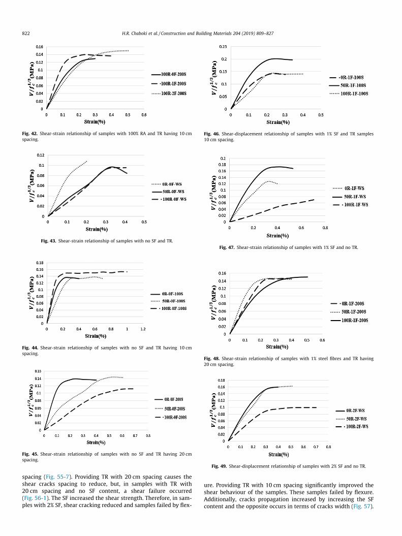
Fig. 44. Shear-strain relationship of samples with no SF and TR having 10 cmspacing.
Fig. 45. Shear-strain relationship of samples with no SF and TR having 20 cmspacing.
Fig. 46. Shear-displacement relationship of samples with 1% SF and TR samples10 cm spacing.
Fig. 47. Shear-strain relationship of samples with 1% SF and no TR.
Fig. 48. Shear-strain relationship of samples with 1% steel fibres and TR having20 cm spacing.
Fig. 49. Shear-displacement relationship of samples with 2% SF and no TR.
Fig. 43. Shear-strain relationship of samples with no SF and TR.
Fig. 42. Shear-strain relationship of samples with 100% RA and TR having 10 cmspacing.
822 H.R. Chaboki et al. / Construction and Building Materials 204 (2019) 809–827
spacing (Fig. 55-7). Providing TR with 20 cm spacing causes theshear cracks spacing to reduce, but, in samples with TR with20 cm spacing and no SF content, a shear failure occurred(Fig. 56-1). The SF increased the shear strength. Therefore, in sam-ples with 2% SF, shear cracking reduced and samples failed by flex-
ure. Providing TR with 10 cm spacing significantly improved theshear behaviour of the samples. These samples failed by flexure.Additionally, cracks propagation increased by increasing the SFcontent and the opposite occurs in terms of cracks width (Fig. 57).
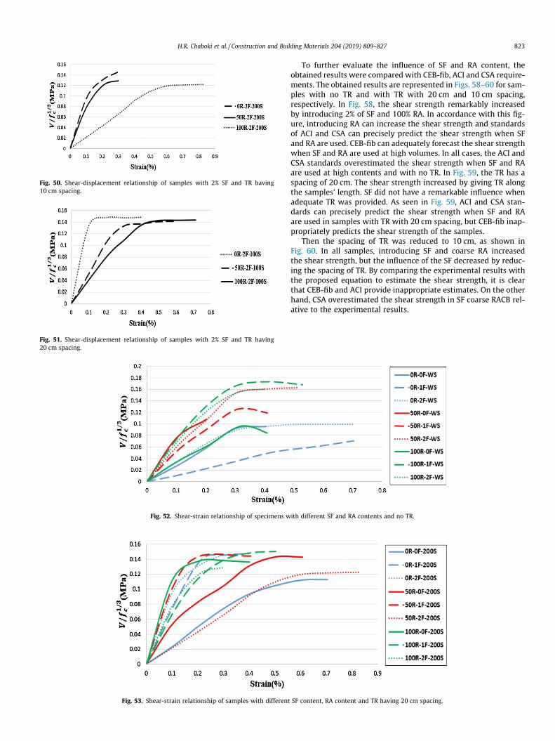
Fig. 52. Shear-strain relationship of specimens w
Fig. 53. Shear-strain relationship of samples with different
Fig. 51. Shear-displacement relationship of samples with 2% SF and TR having20 cm spacing.
Fig. 50. Shear-displacement relationship of samples with 2% SF and TR having10 cm spacing.
H.R. Chaboki et al. / Construction and Building Materials 204 (2019) 809–827 823
To further evaluate the influence of SF and RA content, theobtained results were compared with CEB-fib, ACI and CSA require-ments. The obtained results are represented in Figs. 58–60 for sam-ples with no TR and with TR with 20 cm and 10 cm spacing,respectively. In Fig. 58, the shear strength remarkably increasedby introducing 2% of SF and 100% RA. In accordance with this fig-ure, introducing RA can increase the shear strength and standardsof ACI and CSA can precisely predict the shear strength when SFand RA are used. CEB-fib can adequately forecast the shear strengthwhen SF and RA are used at high volumes. In all cases, the ACI andCSA standards overestimated the shear strength when SF and RAare used at high contents and with no TR. In Fig. 59, the TR has aspacing of 20 cm. The shear strength increased by giving TR alongthe samples’ length. SF did not have a remarkable influence whenadequate TR was provided. As seen in Fig. 59, ACI and CSA stan-dards can precisely predict the shear strength when SF and RAare used in samples with TR with 20 cm spacing, but CEB-fib inap-propriately predicts the shear strength of the samples.
Then the spacing of TR was reduced to 10 cm, as shown inFig. 60. In all samples, introducing SF and coarse RA increasedthe shear strength, but the influence of the SF decreased by reduc-ing the spacing of TR. By comparing the experimental results withthe proposed equation to estimate the shear strength, it is clearthat CEB-fib and ACI provide inappropriate estimates. On the otherhand, CSA overestimated the shear strength in SF coarse RACB rel-ative to the experimental results.
ith different SF and RA contents and no TR.
SF content, RA content and TR having 20 cm spacing.
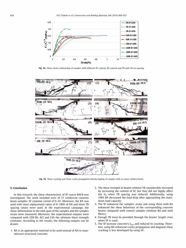
Fig. 55. Shear cracking and shear cracks propagation during loading of samples with no shear reinforcement.
Fig. 54. Shear-strain relationship of samples with different SF content, RA content and TR with 20 cm spacing.
824 H.R. Chaboki et al. / Construction and Building Materials 204 (2019) 809–827
5. Conclusion
In this research, the shear characteristic of SF coarse RACB wasinvestigated. The work included tests of 27 reinforced concretebeam samples. SF contents varied of 0–2%. Moreover, the RA wasused with mass replacement ratios of 0–100% of NA and three TRspacing values were used. In the experimental campaign, theshear-deformation in the mid-span of the samples and the samplesstrain were measured. Moreover, the experimental outputs werecompared with CEB-fib, ACI and CSA the ultimate shear strengthestimates. According to the results, the following outputs can bedrawn:
1. RA is an appropriate material to be used instead of NA to man-ufacture structural concrete;
2. The shear strength in beams without TR considerably increasedby increasing the content of SF, but they did not highly affectthe VR when TR spacing was reduced. Additionally, using100% RA decreased the load drop after approaching the maxi-mum load capacity;
3. The SF enhanced the samples’ strain and using them with RAenhanced the shear behaviour of the corresponding concretebeams compared with control samples (without RA and steelfibres);
4. Enough TR must be provided through the beams’ length, evenwhen SF is used;
5. The SF increase concrete’s fctm and reduced its cracking. There-fore, using RA enhanced cracks propagation and diagonal shearcracking is less developed by using SF;
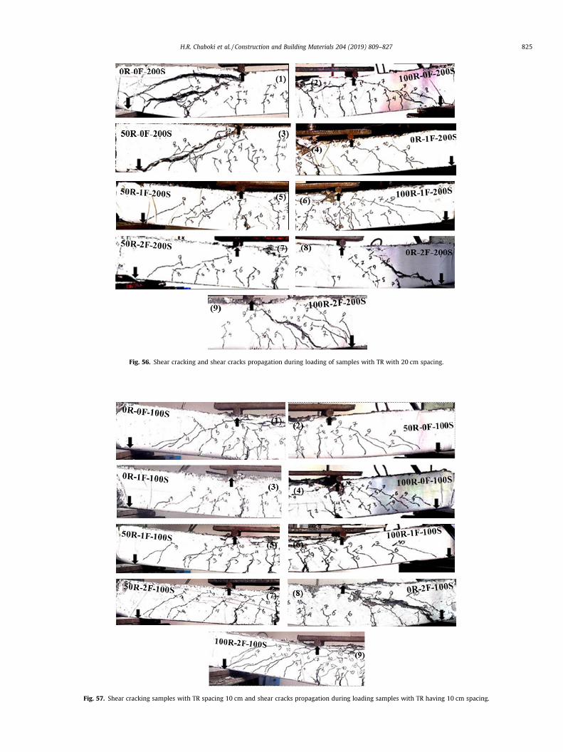
Fig. 57. Shear cracking samples with TR spacing 10 cm and shear cracks propagation during loading samples with TR having 10 cm spacing.
Fig. 56. Shear cracking and shear cracks propagation during loading of samples with TR with 20 cm spacing.
H.R. Chaboki et al. / Construction and Building Materials 204 (2019) 809–827 825
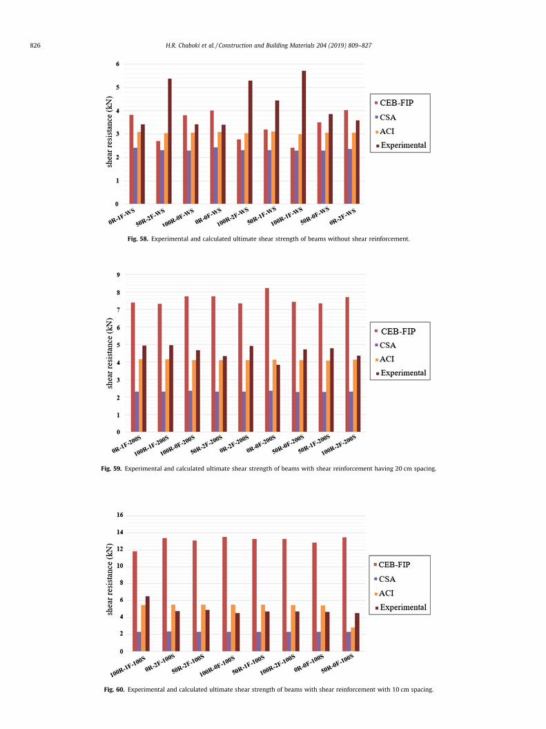
Fig. 60. Experimental and calculated ultimate shear strength of beams with shear reinforcement with 10 cm spacing.
Fig. 59. Experimental and calculated ultimate shear strength of beams with shear reinforcement having 20 cm spacing.
Fig. 58. Experimental and calculated ultimate shear strength of beams without shear reinforcement.
826 H.R. Chaboki et al. / Construction and Building Materials 204 (2019) 809–827
H.R. Chaboki et al. / Construction and Building Materials 204 (2019) 809–827 827
6. By using RA, the ultimate shear strength enhanced in sampleswith different TR spacing. CEB-fib did not sufficiently estimatethe ultimate VR in SF coarse RACB with no TR, while CSA andACI provided appropriate forecast;
7. By decreasing the spacing of TR, the influence of the SF reducedand ACI and CEB-fib provided inappropriate estimates. On theother hand, CSA overestimated the shear strength in SF coarseRACB relative to the experimental results;
8. The SF enhanced the RA beams’ deformation. The samples’deformation increased when 2% SF were introduced to the con-crete mixes.
Conflict of interest
The authors have no conflict of interest whatsoever.
References
[1] B.C. Han, H.D. Yun, S.Y. Chung Shear capacity of reinforced concrete beamsmade with recycled-aggregate. In: Fifth CANMET/ACI International Conferenceon Recent Advantage Concrete Technology: ACI SP-200, 2001, 503–515
[2] K. Eguchi, K. Teranishi, A. Nakagome, H. Kishimoto, K. Shinozaki, M. Narikawa,Application of recycled coarse aggregate by mixture to concrete construction,Construct. Build. Mater. 21 (7) (2007) 1542–1551.
[3] K. Rahal, Mechanical properties of concrete with recycled coarse aggregate,Build. Environ. 42 (1) (2007) 407–415.
[4] B. Gonzalez-Fonteboa, F. Martınez-Abella, Shear strength of recycled concretebeams, Construct. Build. Mater. 21 (4) (2007) 887–893.
[5] M. Etxeberria, A.R. Mari, E. Vazquez, Recycled aggregate concrete as structuralmaterial, Mater. Struct. 40 (2007) 529–541.
[6] G. Fathifazl, A.G. Razaqpur, I.O. Burkan, A. Abbs, B. Fournier, S. Foo, Shearcapacity evaluation of steel reinforced recycled concrete (RRC) beams, Eng.Struct. 33 (2011) 1025–1033.
[7] K.K. Sagoe-Crentsil, T. Brown, A.H. Taylor, Performance of concrete made withcommercially produced coarse recycled concrete aggregate, Cem. Concr. Res.31 (5) (2001) 707–712.
[8] G. Fathifazl, A.G. Razaqpur, I.O. Burkan, A. Abbas, B. Fournier, S. Foo, Shearstrength of reinforced concrete beams with stirrups, Mag. Concr. Res. 62 (2010)685–699.
[9] Q. Zhang, Z. Guo, Investigation on shear strength and shear strain of concrete, J.Construct. Struct. 13 (5) (1992) 17–24.
[10] M. Arezoumandi, A. Smith, J.S. Volz, K.H. Khayat, An experimental study on theshear strength of reinforced concrete beams with 100% recycled concreteaggregate, Constr. Build. Mater. 53 (2014) 612–620.
[11] B.C. Han, H.D. Yun, S.Y. Chung, Shear Capacity of Reinforced Concrete BeamsMade with Recycled Aggregate, ACI Special Publication, 2001.
[12] M. Sogo, T. Sogabe, I. Maruyma, R. Sato, K. Kawai, Shear behaviour of reinforcedrecycled concrete beams, In International RILEM Conference on the Use ofRecycled Materials in Building and Structures, 2004, 610-618.
[13] G. Fathifazl, A.G. Razaqpur, I.O. Burkan, A. Abbas, B. Fournier, S. Foo, Flexuralperformance of steel-reinforced recycled concrete beams, ACI Struct. J. 106(2009) 858–867.
[14] H.B. Choi, C.K. Yi, H.H. Cho, K.I. Kang, Experimental study on the shear strengthof recycled aggregate concrete beams, Mag. Concr. Res. 62 (2010) 103–114.
[15] S. Pradhan, S. Kumar, S.V. Barai, Shear performance of recycled aggregateconcrete beams: An insight for design aspects, Constr. Build. Mater. 178 (2018)593–611.
[16] E.E. Etman, H.M. Afefy, A.T. Baraghith, S.A. Khedr, Improving the shearperformance of reinforced concrete beams made of recycled coarseaggregate, Constr. Build. Mater. 185 (2018) 310–324.
[17] K.N. Rahal, Y.T. Alrefaei, Shear strength of recycled aggregate concrete beamscontaining stirrups, Constr. Build. Mater. 191 (2018) 866–876.
[18] I.S. Ignjatovic, S.B. Marinkovic, N. Tošic, Shear behaviour of recycled aggregateconcrete beams with and without shear reinforcement, Eng. Struct. 141 (2017)386–401.
[19] G. Fathifazl, A.G. Razaqpur, I.O. Burkan, A. Abbas, B. Fournier, S. Foo, Shearcapacity evaluation of steel reinforced recycled concrete (RRC) beams, Eng.Struct. 33 (3) (2011) 1025–1033.
[20] V. Bindiganavile, N. Banthia, Polymer and steel fiber reinforced cementitiouscomposites under impact loading, Part 1: bond-slip response, Am. Concr. Instit.Mater. J. 98 (1) (2001) 10–16.
[21] N. Banthia, J. Sheng, Fracture toughness of micro-fiber reinforced cementcomposites, Cem. Concr. Compos. 18 (1996) 251–269.
[22] D. Gao, L. Zhang, Flexural performance and evaluation method of steel fibrereinforced recycled coarse aggregate concrete, Constr. Build. Mater. 159 (2018)126–136.
[23] D.J. Kim, A.E. Naaman, S. El-Tawil, Comparative flexural behaviour of four fibrereinforced cementitious composites, Cem. Concr. Compos. 30 (2008) 917–928.
[24] F. Altun, B. Aktas, Investigation of reinforced concrete beams behaviour of steelfibre added lightweight concrete, Constr. Build. Mater. 38 (2013) 575–581.
[25] D.Y. Yoo, Y.S. Yoon, N. Banthia, Predicting the post-cracking behaviour ofnormal- and high-strength steel-fibre-reinforced concrete beams, Constr.Build. Mater. 93 (2015) 477–485.
[26] H.C. Mertol, E. Baran, H. Jibril Bello, Flexural behaviour of lightly and heavilyreinforced steel fibre concrete Beams, Constr. Build. Mater. 98 (2015) 185–193.
[27] S.P. Patil, K.K. Single, Tests of steel fibre reinforced concrete beams underpredominant torsion and bending, J. Build. Eng. 352–7102 (2016) 30013–30014.
[28] B. Luccioni, F. Isla, R. Codina, D. Ambrosini, R. Zerbino, G. Giaccio, M.C. Torrijos,Effect of steel fibres on static and blast response of high strength concrete, Int.J. Impact Eng. S0734–743 (2017) 30056–30062.
[29] J.Y. Lee, H.O. Shin, D.Y. Yoo, Y.S. Yoon, Structural response of steel-fibre-reinforced concrete beams under various loading rates, Eng. Struct. 156 (2018)271–283.
[30] M. Mahmod, A.N. Hanoon, H.J. Abed, Flexural behaviour of self-compactingconcrete beams strengthened with steel fibre reinforcement, J. Build. Eng. 16(2018) 228–237.
[31] CSA A23.3-14, Design of concrete structures, a trade-mar k of the CanadianStandards Association, operating as ‘‘CSA Group” published in June 2014 byCSA Group, 2014.
[32] CEB-fib Model Code 2010 Volume 2, International Federation for StructuralConcrete (fib).
[33] ACI 318-08, Building a code requirement for structural concrete andcommentary, Reported by ACI committee 318, 2008.
[34] H. Chaboki, M. Ghalehnovi, A. Karimipour, J. de Brito, Experimental study onthe flexural behaviour and ductility ratio of steel, Constr. Build. Mater. 186(2018) 400–422.