Embed Size (px)
Citation preview
SY
ST
EM
OV
ER
VIE
W
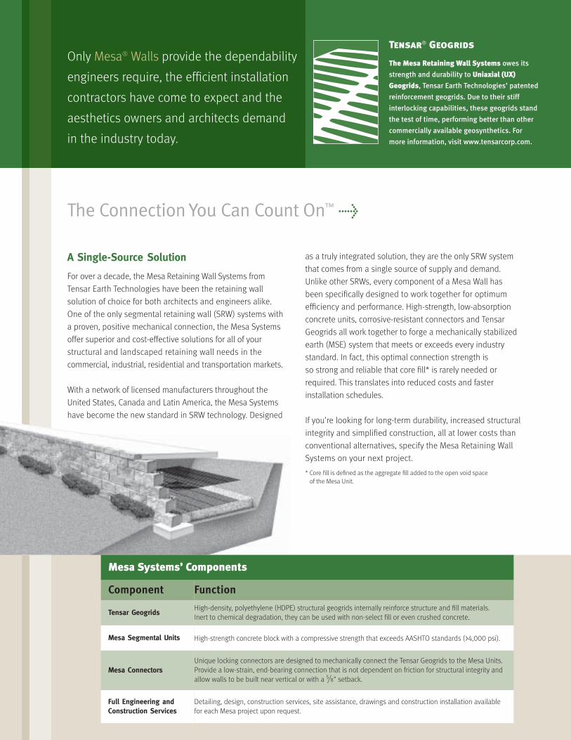
A Single-Source Solution
For over a decade, the Mesa Retaining Wall Systems from
Tensar Earth Technologies have been the retaining wall
solution of choice for both architects and engineers alike.
One of the only segmental retaining wall (SRW) systems with
a proven, positive mechanical connection, the Mesa Systems
offer superior and cost-effective solutions for all of your
structural and landscaped retaining wall needs in the
commercial, industrial, residential and transportation markets.
With a network of licensed manufacturers throughout the
United States, Canada and Latin America, the Mesa Systems
have become the new standard in SRW technology. Designed
as a truly integrated solution, they are the only SRW system
that comes from a single source of supply and demand.
Unlike other SRWs, every component of a Mesa Wall has
been specifically designed to work together for optimum
efficiency and performance. High-strength, low-absorption
concrete units, corrosive-resistant connectors and Tensar
Geogrids all work together to forge a mechanically stabilized
earth (MSE) system that meets or exceeds every industry
standard. In fact, this optimal connection strength is
so strong and reliable that core fill* is rarely needed or
required. This translates into reduced costs and faster
installation schedules.
If you’re looking for long-term durability, increased structural
integrity and simplified construction, all at lower costs than
conventional alternatives, specify the Mesa Retaining Wall
Systems on your next project.
* Core fill is defined as the aggregate fill added to the open void space
of the Mesa Unit.
The Connection You Can Count On™ >
Only Mesa® Walls provide the dependability
engineers require, the efficient installation
contractors have come to expect and the
aesthetics owners and architects demand
in the industry today.
Tensar® Geogrids
The Mesa Retaining Wall Systems owes its
strength and durability to Uniaxial (UX)
Geogrids, Tensar Earth Technologies’ patented
reinforcement geogrids. Due to their stiff
interlocking capabilities, these geogrids stand
the test of time, performing better than other
commercially available geosynthetics. For
more information, visit www.tensarcorp.com.
Mesa Systems’ Components
Component Function
Tensar GeogridsHigh-density, polyethylene (HDPE) structural geogrids internally reinforce structure and fill materials.
Inert to chemical degradation, they can be used with non-select fill or even crushed concrete.
Mesa Segmental Units High-strength concrete block with a compressive strength that exceeds AASHTO standards (>4,000 psi).
Mesa ConnectorsUnique locking connectors are designed to mechanically connect the Tensar Geogrids to the Mesa Units.
Provide a low-strain, end-bearing connection that is not dependent on friction for structural integrity and
allow walls to be built near vertical or with a 5/8" setback.
Full Engineering and Construction Services
Detailing, design, construction services, site assistance, drawings and construction installation available
for each Mesa project upon request.
Unlimited Landscapes, Structural Solutions
Whether you’re increasing useable land or improving
property value, the Mesa Systems can solve your most
challenging grade change requirements with a full line
of SRW products. From building large structural walls to
small tiered gardens, Mesa units blend effortlessly with the
natural surroundings of any site.
Aesthetically Versatile
Whether you’re creating stairs, 90-degree corners, or convex
or concave curves, Mesa Walls can easily accommodate a
variety of design considerations. Based on your specific
aesthetic requirements, units can be variegated by color and
texture, and walls can even be built by mixing different facing
options. Designs are limitless – architects and designers are
bound only by their imaginations.
Full Line of Products >
2
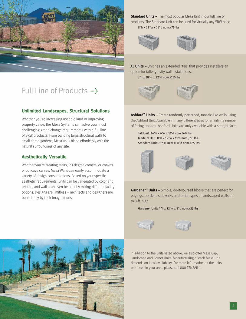
Standard Units – The most popular Mesa Unit in our full line of
products. The Standard Unit can be used for virtually any SRW need.
8"h x 18"w x 11"d nom./75 lbs.
XL Units – Unit has an extended “tail” that provides installers an
option for taller gravity wall installations.
8"h x 18"w x 22"d nom./110 lbs.
Ashford™ Units – Create randomly patterned, mosaic-like walls using
the Ashford Unit. Available in many different sizes for an infinite number
of facing options. Ashford Units are only available with a straight face.
Tall Unit: 16"h x 6"w x 11"d nom./60 lbs.
Medium Unit: 8"h x 12"w x 11"d nom./60 lbs.
Standard Unit: 8"h x 18"w x 11"d nom./75 lbs.
Gardener™ Units – Simple, do-it-yourself blocks that are perfect for
edgings, borders, sidewalks and other types of landscaped walls up
to 3-ft. high.
Gardener Unit: 4"h x 12"w x 8"d nom./25 lbs.
In addition to the units listed above, we also offer Mesa Cap,
Landscape and Corner Units. Manufacturing of each Mesa Unit
depends on local availability. For more information on the units
produced in your area, please call 800-TENSAR-1.
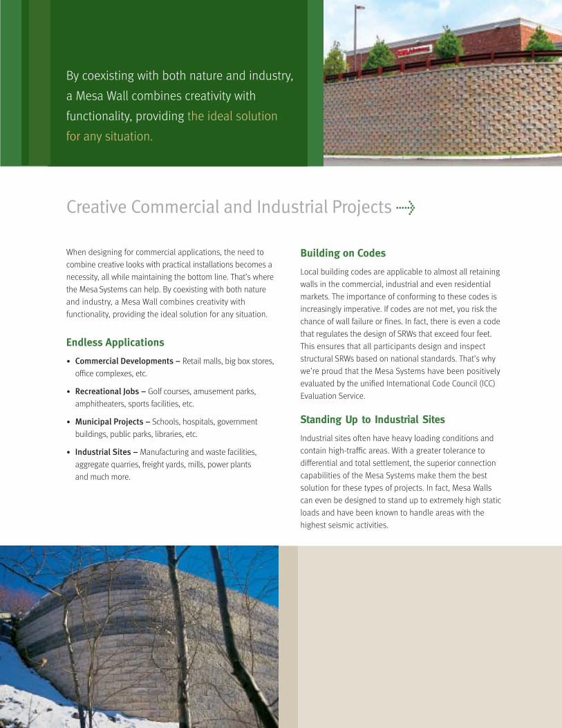
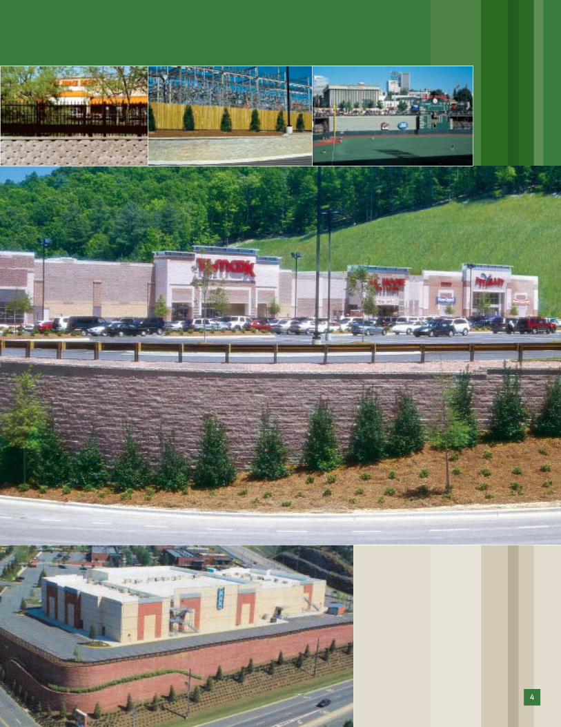
Creative Commercial and Industrial Projects >
When designing for commercial applications, the need to
combine creative looks with practical installations becomes a
necessity, all while maintaining the bottom line. That’s where
the Mesa Systems can help. By coexisting with both nature
and industry, a Mesa Wall combines creativity with
functionality, providing the ideal solution for any situation.
Endless Applications
• Commercial Developments – Retail malls, big box stores,
office complexes, etc.
• Recreational Jobs – Golf courses, amusement parks,
amphitheaters, sports facilities, etc.
• Municipal Projects – Schools, hospitals, government
buildings, public parks, libraries, etc.
• Industrial Sites – Manufacturing and waste facilities,
aggregate quarries, freight yards, mills, power plants
and much more.
Building on Codes
Local building codes are applicable to almost all retaining
walls in the commercial, industrial and even residential
markets. The importance of conforming to these codes is
increasingly imperative. If codes are not met, you risk the
chance of wall failure or fines. In fact, there is even a code
that regulates the design of SRWs that exceed four feet.
This ensures that all participants design and inspect
structural SRWs based on national standards. That’s why
we’re proud that the Mesa Systems have been positively
evaluated by the unified International Code Council (ICC)
Evaluation Service.
Standing Up to Industrial Sites
Industrial sites often have heavy loading conditions and
contain high-traffic areas. With a greater tolerance to
differential and total settlement, the superior connection
capabilities of the Mesa Systems make them the best
solution for these types of projects. In fact, Mesa Walls
can even be designed to stand up to extremely high static
loads and have been known to handle areas with the
highest seismic activities.
By coexisting with both nature and industry,
a Mesa Wall combines creativity with
functionality, providing the ideal solution
for any situation.
4
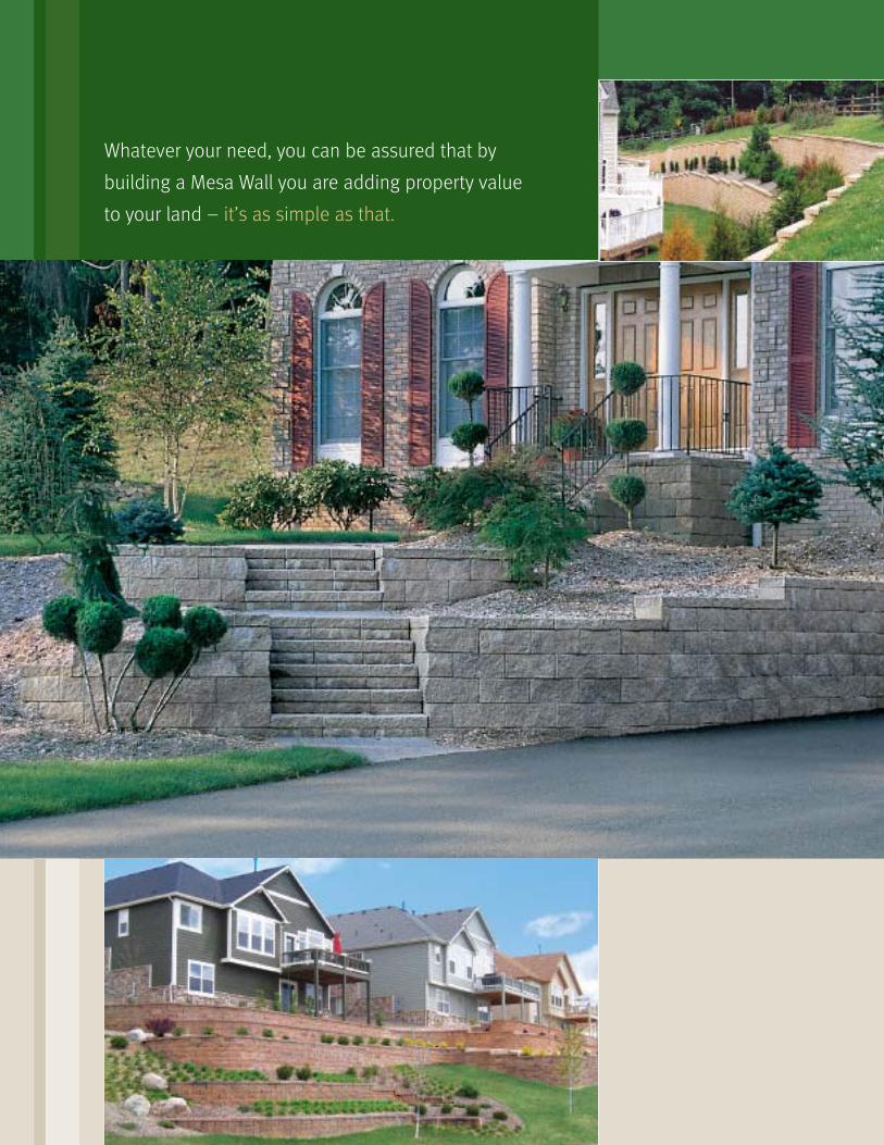
Whatever your need, you can be assured that by
building a Mesa Wall you are adding property value
to your land – it’s as simple as that.
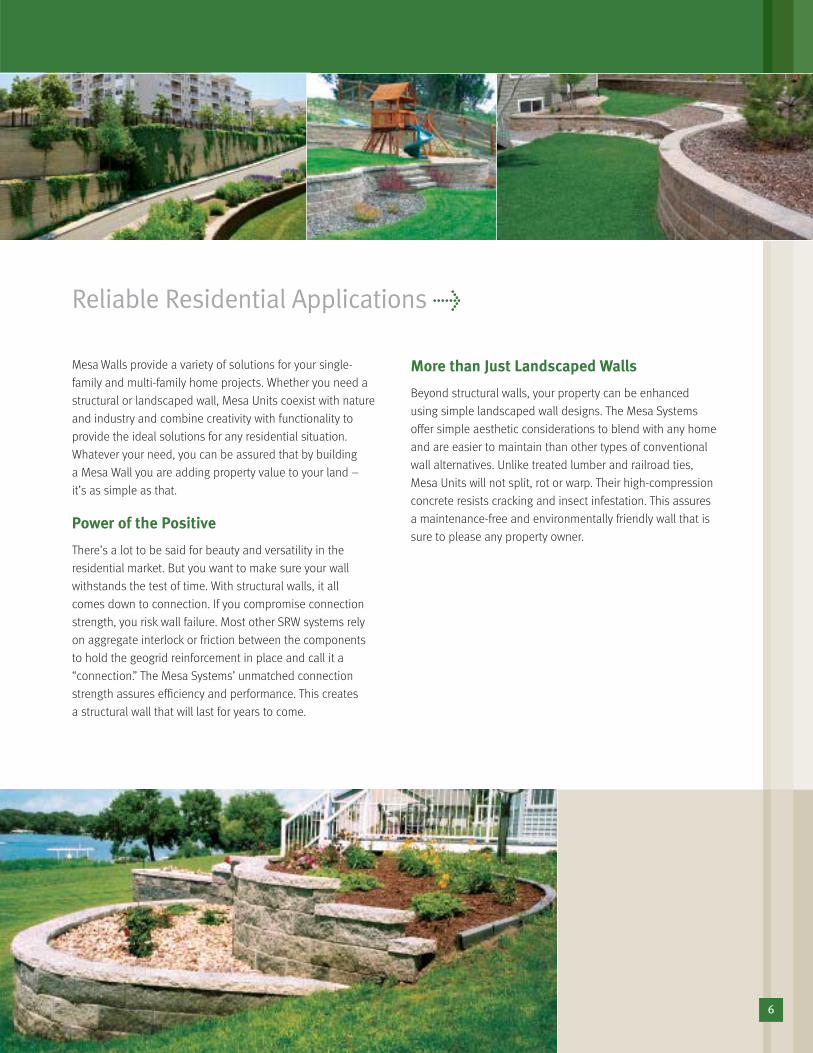
Reliable Residential Applications >
Mesa Walls provide a variety of solutions for your single-
family and multi-family home projects. Whether you need a
structural or landscaped wall, Mesa Units coexist with nature
and industry and combine creativity with functionality to
provide the ideal solutions for any residential situation.
Whatever your need, you can be assured that by building
a Mesa Wall you are adding property value to your land –
it’s as simple as that.
Power of the Positive
There’s a lot to be said for beauty and versatility in the
residential market. But you want to make sure your wall
withstands the test of time. With structural walls, it all
comes down to connection. If you compromise connection
strength, you risk wall failure. Most other SRW systems rely
on aggregate interlock or friction between the components
to hold the geogrid reinforcement in place and call it a
“connection.” The Mesa Systems’ unmatched connection
strength assures efficiency and performance. This creates
a structural wall that will last for years to come.
More than Just Landscaped Walls
Beyond structural walls, your property can be enhanced
using simple landscaped wall designs. The Mesa Systems
offer simple aesthetic considerations to blend with any home
and are easier to maintain than other types of conventional
wall alternatives. Unlike treated lumber and railroad ties,
Mesa Units will not split, rot or warp. Their high-compression
concrete resists cracking and insect infestation. This assures
a maintenance-free and environmentally friendly wall that is
sure to please any property owner.
6
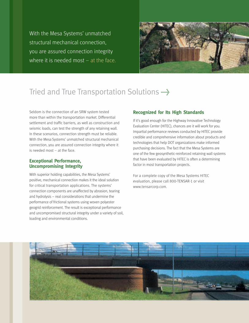
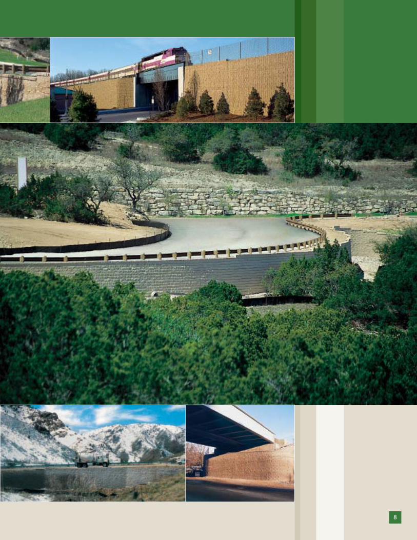
Tried and True Transportation Solutions >
With the Mesa Systems’ unmatched
structural mechanical connection,
you are assured connection integrity
where it is needed most – at the face.
Seldom is the connection of an SRW system tested
more than within the transportation market. Differential
settlement and traffic barriers, as well as construction and
seismic loads, can test the strength of any retaining wall.
In these scenarios, connection strength must be reliable.
With the Mesa Systems’ unmatched structural mechanical
connection, you are assured connection integrity where it
is needed most – at the face.
Exceptional Performance, Uncompromising Integrity
With superior holding capabilities, the Mesa Systems’
positive, mechanical connection makes it the ideal solution
for critical transportation applications. The systems’
connection components are unaffected by abrasion, tearing
and hydrolysis – real considerations that undermine the
performance of frictional systems using woven polyester
geogrid reinforcement. The result is exceptional performance
and uncompromised structural integrity under a variety of soil,
loading and environmental conditions.
Recognized for Its High Standards
If it’s good enough for the Highway Innovative Technology
Evaluation Center (HITEC), chances are it will work for you.
Impartial performance reviews conducted by HITEC provide
credible and comprehensive information about products and
technologies that help DOT organizations make informed
purchasing decisions. The fact that the Mesa Systems are
one of the few geosynthetic-reinforced retaining wall systems
that have been evaluated by HITEC is often a determining
factor in most transportation projects.
For a complete copy of the Mesa Systems HITEC
evaluation, please call 800-TENSAR-1 or visit
www.tensarcorp.com.
8
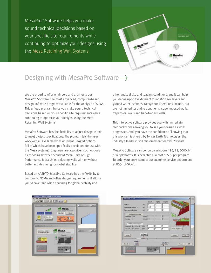
MesaPro™ Software helps you make
sound technical decisions based on
your specific site requirements while
continuing to optimize your designs using
the Mesa Retaining Wall Systems.
Designing with MesaPro Software >
We are proud to offer engineers and architects our
MesaPro Software, the most advanced, computer-based
design software program available for the analysis of SRWs.
This unique program helps you make sound technical
decisions based on your specific site requirements while
continuing to optimize your designs using the Mesa
Retaining Wall Systems.
MesaPro Software has the flexibility to adjust design criteria
to meet project specifications. The program lets the user
work with all available types of Tensar Geogrid options
(all of which have been specifically developed for use with
the Mesa Systems). Engineers are also given such options
as choosing between Standard Mesa Units or High
Performance Mesa Units, selecting walls with or without
batter and designing for global stability.
Based on AASHTO, MesaPro Software has the flexibility to
conform to NCMA and other design requirements. It allows
you to save time when analyzing for global stability and
other unusual site and loading conditions, and it can help
you define up to five different foundation soil layers and
ground water locations. Design considerations include, but
are not limited to: bridge abutments, superimposed walls,
trapezoidal walls and back-to-back walls.
This interactive software provides you with immediate
feedback while allowing you to see your design as work
progresses. And, you have the confidence of knowing that
this program is offered by Tensar Earth Technologies, the
industry’s leader in soil reinforcement for over 20 years.
MesaPro Software can be run on Windows® 95, 98, 2000, NT
or XP platforms. It is available at a cost of $99 per program.
To order your copy, contact our customer service department
at 800-TENSAR-1.
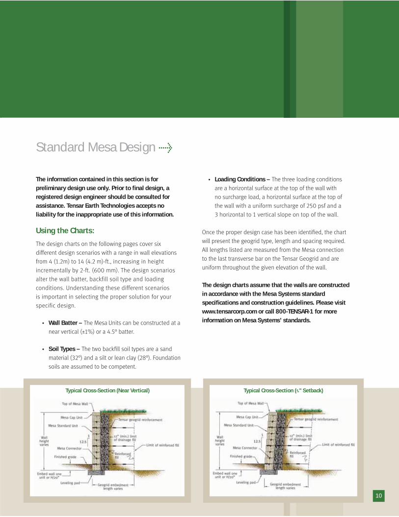
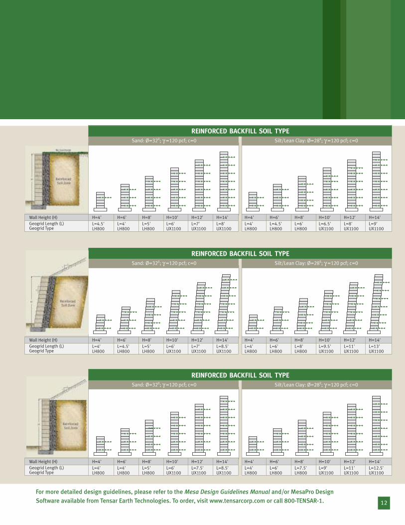
Standard Mesa Design >
The information contained in this section is for preliminary design use only. Prior to final design, aregistered design engineer should be consulted forassistance. Tensar Earth Technologies accepts no liability for the inappropriate use of this information.
Using the Charts:The design charts on the following pages cover six
different design scenarios with a range in wall elevations
from 4 (1.2m) to 14 (4.2 m)-ft., increasing in height
incrementally by 2-ft. (600 mm). The design scenarios
alter the wall batter, backfill soil type and loading
conditions. Understanding these different scenarios
is important in selecting the proper solution for your
specific design.
• Wall Batter – The Mesa Units can be constructed at a
near vertical (±1%) or a 4.5° batter.
• Soil Types – The two backfill soil types are a sand
material (32°) and a silt or lean clay (28°). Foundation
soils are assumed to be competent.
• Loading Conditions – The three loading conditions
are a horizontal surface at the top of the wall with
no surcharge load, a horizontal surface at the top of
the wall with a uniform surcharge of 250 psf and a
3 horizontal to 1 vertical slope on top of the wall.
Once the proper design case has been identified, the chart
will present the geogrid type, length and spacing required.
All lengths listed are measured from the Mesa connection
to the last transverse bar on the Tensar Geogrid and are
uniform throughout the given elevation of the wall.
The design charts assume that the walls are constructed in accordance with the Mesa Systems standard specifications and construction guidelines. Please visitwww.tensarcorp.com or call 800-TENSAR-1 for moreinformation on Mesa Systems’ standards.
Typical Cross-Section (Near Vertical) Typical Cross-Section (5/8" Setback)
10
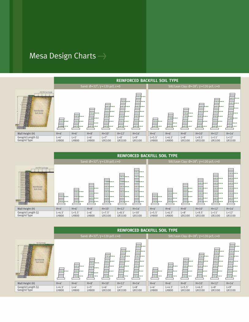
Sand: Ø=32º; γ =120 pcf; c=0
Geogrid Length (L) Geogrid Type
Wall Height (H) H=4' H=6' H=8' H=10' H=12' H=14'L=4' L=6'L=5' L=7' L=8' L=9'LH800 LH800 LH800 UX1100 UX1100 UX1100
Silt/Lean Clay: Ø=28º; γ =120 pcf; c=0
H=4' H=6' H=8' H=10' H=12' H=14'L=5.5' L=6.5' L=8' L=9.5' L=11' L=12'LH800 LH800 UX1100 UX1100 UX1100 UX1100
REINFORCED BACKFILL SOIL TYPE
Sand: Ø=32º; γ =120 pcf; c=0
Geogrid Length (L) Geogrid Type
Wall Height (H) H=4' H=6' H=8' H=10' H=12' H=14'L=4.5' L=6'L=5.5' L=7.5' L=8.5' L=10'LH800 LH800 LH800 UX1100 UX1100 UX1100
Silt/Lean Clay: Ø=28º; γ =120 pcf; c=0
H=4' H=6' H=8' H=10' H=12' H=14'L=5.5' L=6.5' L=8' L=9.5' L=11' L=12'LH800 LH800 UX1100 UX1100 UX1100 UX1100
REINFORCED BACKFILL SOIL TYPE
Sand: Ø=32º; γ =120 pcf; c=0
Geogrid Length (L) Geogrid Type
Wall Height (H) H=4' H=6' H=8' H=10' H=12' H=14'L=4.5' L=5'L=4' L=6' L=7' L=8'LH800 LH800 LH800 UX1100 UX1100 UX1100
Silt/Lean Clay: Ø=28º; γ =120 pcf; c=0
H=4' H=6' H=8' H=10' H=12' H=14'L=4' L=4.5' L=5.5' L=6.5' L=8' L=9'LH800 LH800 UX1100 UX1100 UX1100 UX1100
REINFORCED BACKFILL SOIL TYPE
Mesa Design Charts >
12
Sand: Ø=32º; γ =120 pcf; c=0
Geogrid Length (L) Geogrid Type
Wall Height (H) H=4' H=6' H=8' H=10' H=12' H=14'L=4.5' L=5'L=4' L=6' L=7' L=8'LH800 LH800 LH800 UX1100 UX1100 UX1100
Silt/Lean Clay: Ø=28º; γ =120 pcf; c=0
H=4' H=6' H=8' H=10' H=12' H=14'L=4' L=4.5' L=6' L=6.5' L=8' L=9'LH800 LH800 LH800 UX1100 UX1100 UX1100
REINFORCED BACKFILL SOIL TYPE
Sand: Ø=32º; γ =120 pcf; c=0
Geogrid Length (L) Geogrid Type
Wall Height (H) H=4' H=6' H=8' H=10' H=12' H=14'L=4' L=5'L=4.5' L=6' L=7' L=8.5'LH800 LH800 LH800 UX1100 UX1100 UX1100
Silt/Lean Clay: Ø=28º; γ =120 pcf; c=0
H=4' H=6' H=8' H=10' H=12' H=14'L=4' L=6' L=8' L=9.5' L=11' L=13'LH800 LH800 LH800 UX1100 UX1100 UX1100
REINFORCED BACKFILL SOIL TYPE
Sand: Ø=32º; γ =120 pcf; c=0
Geogrid Length (L) Geogrid Type
Wall Height (H) H=4' H=6' H=8' H=10' H=12' H=14'L=4' L=5'L=4' L=6' L=7.5' L=8.5'LH800 LH800 LH800 UX1100 UX1100 UX1100
Silt/Lean Clay: Ø=28º; γ =120 pcf; c=0
H=4' H=6' H=8' H=10' H=12' H=14'L=4' L=6' L=7.5' L=9' L=11' L=12.5'LH800 LH800 LH800 UX1100 UX1100 UX1100
REINFORCED BACKFILL SOIL TYPE
For more detailed design guidelines, please refer to the Mesa Design Guidelines Manual and/or MesaPro DesignSoftware available from Tensar Earth Technologies. To order, visit www.tensarcorp.com or call 800-TENSAR-1.
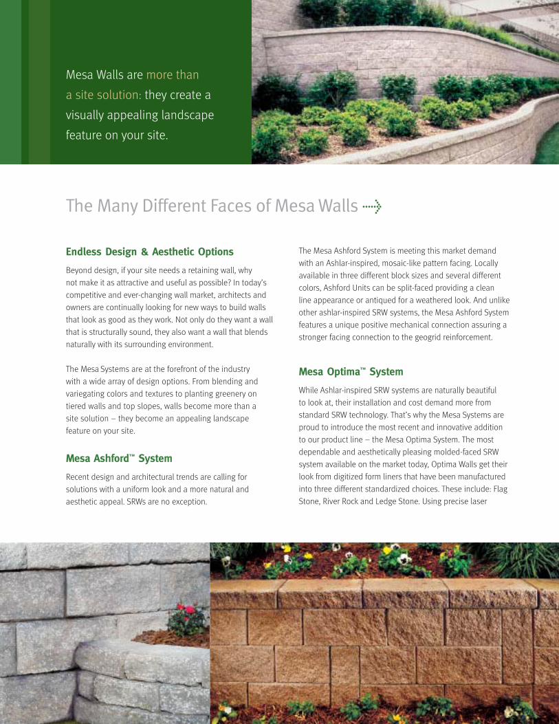
The Many Different Faces of Mesa Walls >
Endless Design & Aesthetic Options
Beyond design, if your site needs a retaining wall, why
not make it as attractive and useful as possible? In today’s
competitive and ever-changing wall market, architects and
owners are continually looking for new ways to build walls
that look as good as they work. Not only do they want a wall
that is structurally sound, they also want a wall that blends
naturally with its surrounding environment.
The Mesa Systems are at the forefront of the industry
with a wide array of design options. From blending and
variegating colors and textures to planting greenery on
tiered walls and top slopes, walls become more than a
site solution – they become an appealing landscape
feature on your site.
Mesa Ashford™ System
Recent design and architectural trends are calling for
solutions with a uniform look and a more natural and
aesthetic appeal. SRWs are no exception.
The Mesa Ashford System is meeting this market demand
with an Ashlar-inspired, mosaic-like pattern facing. Locally
available in three different block sizes and several different
colors, Ashford Units can be split-faced providing a clean
line appearance or antiqued for a weathered look. And unlike
other ashlar-inspired SRW systems, the Mesa Ashford System
features a unique positive mechanical connection assuring a
stronger facing connection to the geogrid reinforcement.
Mesa Optima™ System
While Ashlar-inspired SRW systems are naturally beautiful
to look at, their installation and cost demand more from
standard SRW technology. That’s why the Mesa Systems are
proud to introduce the most recent and innovative addition
to our product line – the Mesa Optima System. The most
dependable and aesthetically pleasing molded-faced SRW
system available on the market today, Optima Walls get their
look from digitized form liners that have been manufactured
into three different standardized choices. These include: Flag
Stone, River Rock and Ledge Stone. Using precise laser
Mesa Walls are more than
a site solution: they create a
visually appealing landscape
feature on your site.
technology to recreate natural stone facings, a three-
dimensional image is superimposed onto the face of a Mesa
Standard Unit. The result is an unmatched, visually attractive,
structural SRW solution that remains both cost-effective and
easy-to-install.
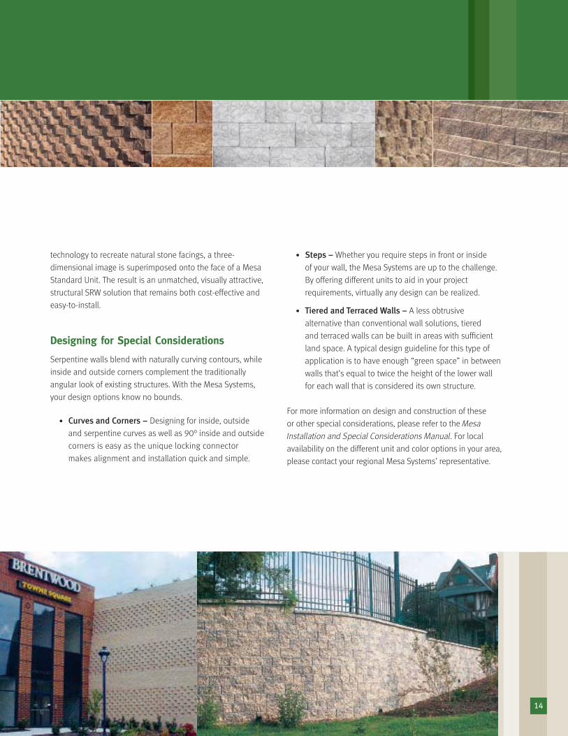
Designing for Special Considerations
Serpentine walls blend with naturally curving contours, while
inside and outside corners complement the traditionally
angular look of existing structures. With the Mesa Systems,
your design options know no bounds.
• Curves and Corners – Designing for inside, outside
and serpentine curves as well as 90° inside and outside
corners is easy as the unique locking connector
makes alignment and installation quick and simple.
• Steps – Whether you require steps in front or inside
of your wall, the Mesa Systems are up to the challenge.
By offering different units to aid in your project
requirements, virtually any design can be realized.
• Tiered and Terraced Walls – A less obtrusive
alternative than conventional wall solutions, tiered
and terraced walls can be built in areas with sufficient
land space. A typical design guideline for this type of
application is to have enough “green space” in between
walls that’s equal to twice the height of the lower wall
for each wall that is considered its own structure.
For more information on design and construction of these
or other special considerations, please refer to the Mesa
Installation and Special Considerations Manual. For local
availability on the different unit and color options in your area,
please contact your regional Mesa Systems’ representative.
14
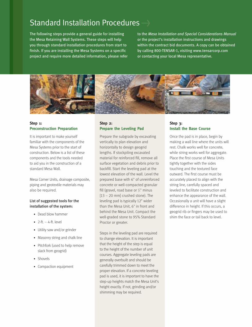
Step 1:Preconstruction Preparation
It is important to make yourself
familiar with the components of the
Mesa Systems prior to the start of
construction. Below is a list of these
components and the tools needed
to aid you in the construction of a
standard Mesa Wall.
Mesa Corner Units, drainage composite,
piping and geotextile materials may
also be required.
List of suggested tools for the installation of the system:
• Dead blow hammer
• 2-ft. – 4-ft. level
• Utility saw and/or grinder
• Masonry string and chalk line
• Pitchfork (used to help remove
slack from geogrid)
• Shovels
• Compaction equipment
Step 2:Prepare the Leveling Pad
Prepare the subgrade by excavating
vertically to plan elevation and
horizontally to design geogrid
lengths. If stockpiling excavated
material for reinforced fill, remove all
surface vegetation and debris prior to
backfill. Start the leveling pad at the
lowest elevation of the wall. Level the
prepared base with 6" of unreinforced
concrete or well-compacted granular
fill (gravel, road base or 3/4" minus
[13 – 20 mm] crushed stone). The
leveling pad is typically 12" wider
than the Mesa Unit, 6" in front and
behind the Mesa Unit. Compact the
well-graded stone to 95% Standard
Proctor or greater.
Steps in the leveling pad are required
to change elevation. It is important
that the height of the step is equal
to the height of the number of unit
courses. Aggregate leveling pads are
generally overbuilt and should be
carefully trimmed down to meet the
proper elevation. If a concrete leveling
pad is used, it is important to have the
step-up heights match the Mesa Unit’s
height exactly. If not, grinding and/or
shimming may be required.
Step 3:Install the Base Course
Once the pad is in place, begin by
making a wall line where the units will
rest. Chalk works well for concrete,
while string works well for aggregate.
Place the first course of Mesa Units
tightly together with the sides
touching and the textured face
outward. The first course must be
accurately placed to align with the
string line, carefully spaced and
leveled to facilitate construction and
enhance the appearance of the wall.
Occasionally a unit will have a slight
difference in height. If this occurs, a
geogrid rib or fingers may be used to
shim the face or tail back to level.
The following steps provide a general guide for installingthe Mesa Retaining Wall Systems. These steps will help you through standard installation procedures from start tofinish. If you are installing the Mesa Systems on a specificproject and require more detailed information, please refer
to the Mesa Installation and Special Considerations Manualor the project’s installation instructions and drawingswithin the contract bid documents. A copy can be obtainedby calling 800-TENSAR-1, visiting www.tensarcorp.comor contacting your local Mesa representative.
Standard Installation Procedures >
16
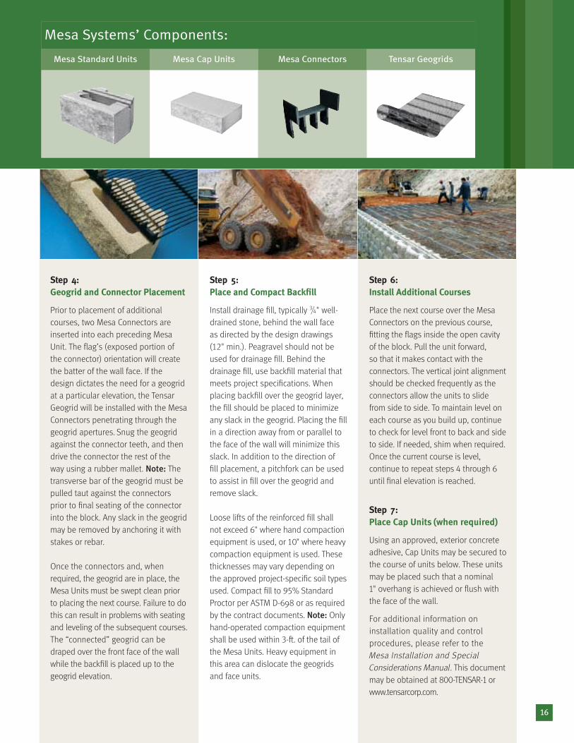
Step 4:Geogrid and Connector Placement
Prior to placement of additional
courses, two Mesa Connectors are
inserted into each preceding Mesa
Unit. The flag’s (exposed portion of
the connector) orientation will create
the batter of the wall face. If the
design dictates the need for a geogrid
at a particular elevation, the Tensar
Geogrid will be installed with the Mesa
Connectors penetrating through the
geogrid apertures. Snug the geogrid
against the connector teeth, and then
drive the connector the rest of the
way using a rubber mallet. Note: The
transverse bar of the geogrid must be
pulled taut against the connectors
prior to final seating of the connector
into the block. Any slack in the geogrid
may be removed by anchoring it with
stakes or rebar.
Once the connectors and, when
required, the geogrid are in place, the
Mesa Units must be swept clean prior
to placing the next course. Failure to do
this can result in problems with seating
and leveling of the subsequent courses.
The “connected” geogrid can be
draped over the front face of the wall
while the backfill is placed up to the
geogrid elevation.
Step 5:Place and Compact Backfill
Install drainage fill, typically 3/4" well-
drained stone, behind the wall face
as directed by the design drawings
(12" min.). Peagravel should not be
used for drainage fill. Behind the
drainage fill, use backfill material that
meets project specifications. When
placing backfill over the geogrid layer,
the fill should be placed to minimize
any slack in the geogrid. Placing the fill
in a direction away from or parallel to
the face of the wall will minimize this
slack. In addition to the direction of
fill placement, a pitchfork can be used
to assist in fill over the geogrid and
remove slack.
Loose lifts of the reinforced fill shall
not exceed 6" where hand compaction
equipment is used, or 10" where heavy
compaction equipment is used. These
thicknesses may vary depending on
the approved project-specific soil types
used. Compact fill to 95% Standard
Proctor per ASTM D-698 or as required
by the contract documents. Note: Only
hand-operated compaction equipment
shall be used within 3-ft. of the tail of
the Mesa Units. Heavy equipment in
this area can dislocate the geogrids
and face units.
Step 6:Install Additional Courses
Place the next course over the Mesa
Connectors on the previous course,
fitting the flags inside the open cavity
of the block. Pull the unit forward,
so that it makes contact with the
connectors. The vertical joint alignment
should be checked frequently as the
connectors allow the units to slide
from side to side. To maintain level on
each course as you build up, continue
to check for level front to back and side
to side. If needed, shim when required.
Once the current course is level,
continue to repeat steps 4 through 6until final elevation is reached.
Step 7:Place Cap Units (when required)
Using an approved, exterior concrete
adhesive, Cap Units may be secured to
the course of units below. These units
may be placed such that a nominal
1" overhang is achieved or flush with
the face of the wall.
For additional information on
installation quality and control
procedures, please refer to the
Mesa Installation and SpecialConsiderations Manual. This document
may be obtained at 800-TENSAR-1 orwww.tensarcorp.com.
Mesa Systems’ Components:
Mesa Standard Units Mesa Cap Units Mesa Connectors Tensar Geogrids
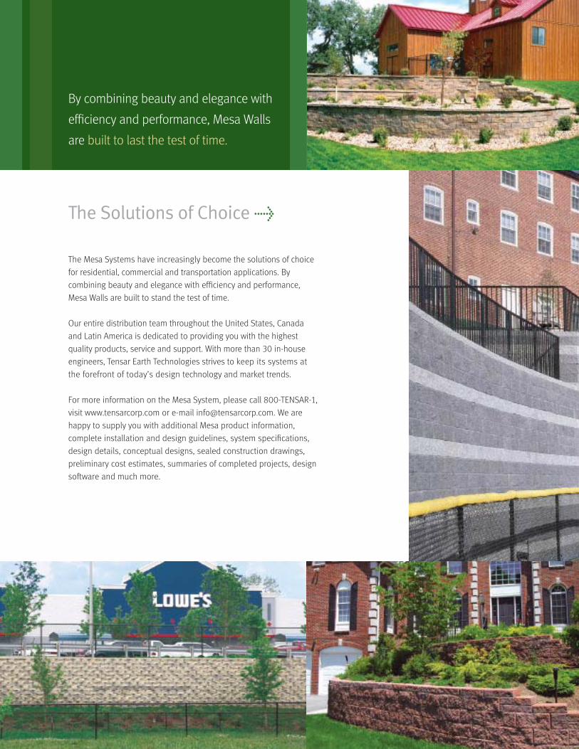
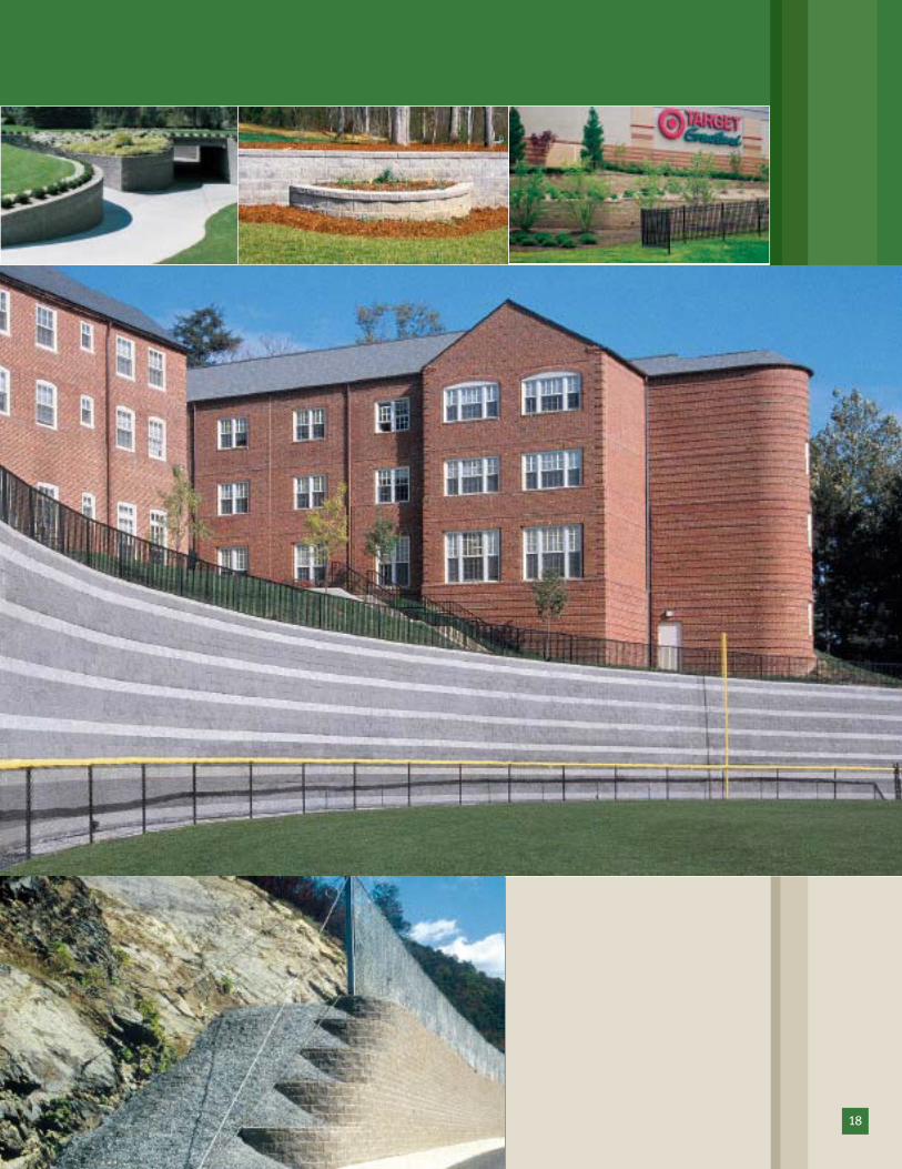
The Mesa Systems have increasingly become the solutions of choice
for residential, commercial and transportation applications. By
combining beauty and elegance with efficiency and performance,
Mesa Walls are built to stand the test of time.
Our entire distribution team throughout the United States, Canada
and Latin America is dedicated to providing you with the highest
quality products, service and support. With more than 30 in-house
engineers, Tensar Earth Technologies strives to keep its systems at
the forefront of today’s design technology and market trends.
For more information on the Mesa System, please call 800-TENSAR-1,
visit www.tensarcorp.com or e-mail [email protected]. We are
happy to supply you with additional Mesa product information,
complete installation and design guidelines, system specifications,
design details, conceptual designs, sealed construction drawings,
preliminary cost estimates, summaries of completed projects, design
software and much more.
The Solutions of Choice >
By combining beauty and elegance with
efficiency and performance, Mesa Walls
are built to last the test of time.
18
Tensar Earth Technologies, Inc.
5883 Glenridge Drive, Suite 200
Atlanta, Georgia 30328
800-TENSAR-1
www.tensarcorp.com
AuthorizedRepresentative:
MESA_BRO_ALL_E_1.06
©2006, Tensar Earth Technologies, Inc. Certain products and/or applications described or illustrated herein are protectedunder one or more U.S. patents. Other U.S. patents are pending, and certain foreign patents and patent applications mayalso exist. Trademark rights also apply as indicated herein. Final determination of the suitability of any information ormaterial for the use contemplated, and its manner of use, is the sole responsibility of the user. Printed in the U.S.A.