Embed Size (px)
Citation preview

Advanced
fiber glass
technology
for asphalt
pavement
overlays
manualmanual
technical


GLASGRlD®
Technical Manual
I. WHAT IS REFLECTIVE CRACKING
II. TESTING REFLECTIVE CRACK PROPERTIES OFOVERLAYS
III. GLASGRID® PERFORMANCE
IV. ENGINEER CHECKLIST FOR SPECIFYING OVERLAYREINFORCEMENT
V. GLASGRID® REINFORCED OVERLAY DESIGNGUIDELINES AND LIMITATIONS
VI. SPECIAL CONTRACT PROVISIONS FOR GLASGRID®
VII.TYPICAL DESIGN CROSS SECTION
- 1 -
Advanced
fiber glass
technology
for asphalt
pavement
overlays
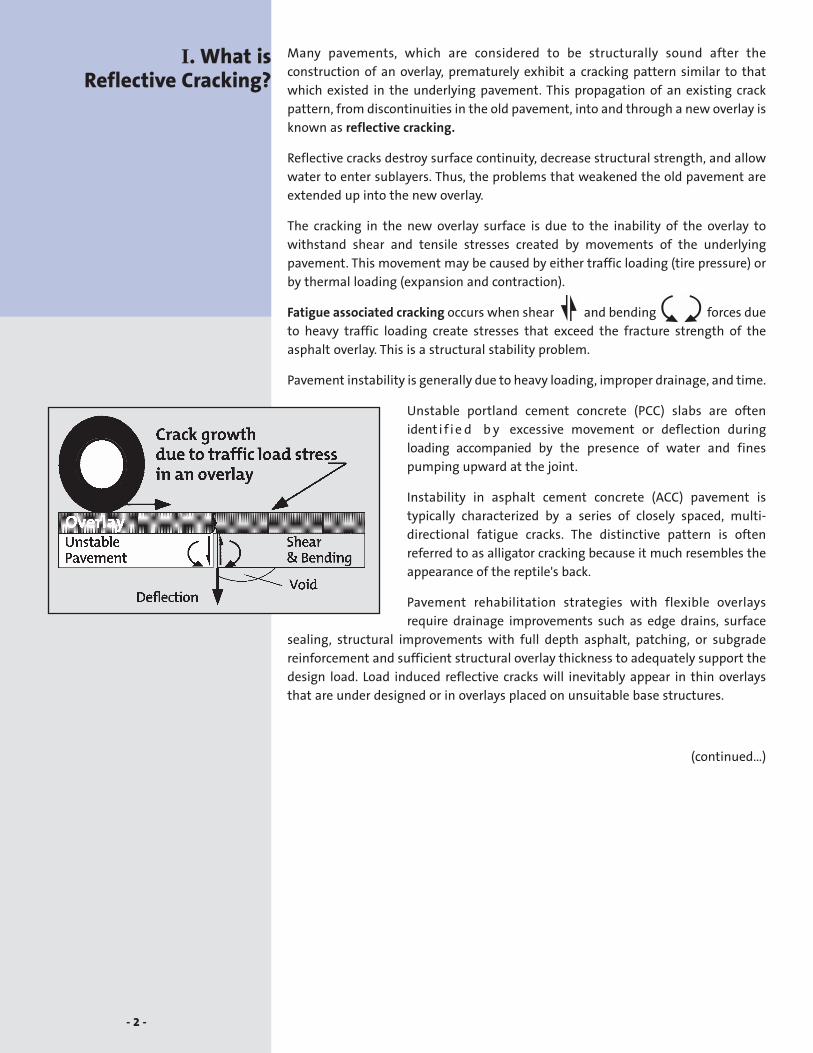
Many pavements, which are considered to be structurally sound after the
construction of an overlay, prematurely exhibit a cracking pattern similar to that
which existed in the underlying pavement. This propagation of an existing crack
pattern, from discontinuities in the old pavement, into and through a new overlay is
known as reflective cracking.
Reflective cracks destroy surface continuity, decrease structural strength, and allow
water to enter sublayers. Thus, the problems that weakened the old pavement are
extended up into the new overlay.
The cracking in the new overlay surface is due to the inability of the overlay to
withstand shear and tensile stresses created by movements of the underlying
pavement. This movement may be caused by either traffic loading (tire pressure) or
by thermal loading (expansion and contraction).
Fatigue associated cracking occurs when shear and bending forces due
to heavy traffic loading create stresses that exceed the fracture strength of the
asphalt overlay. This is a structural stability problem.
Pavement instability is generally due to heavy loading, improper drainage, and time.
Unstable portland cement concrete (PCC) slabs are often
ident i f i e d b y excessive movement or deflection during
loading accompanied by the presence of water and fines
pumping upward at the joint.
Instability in asphalt cement concrete (ACC) pavement is
typically characterized by a series of closely spaced, multi-
directional fatigue cracks. The distinctive pattern is often
referred to as alligator cracking because it much resembles the
appearance of the reptile's back.
Pavement rehabilitation strategies with flexible overlays
require drainage improvements such as edge drains, surface
sealing, structural improvements with full depth asphalt, patching, or subgrade
reinforcement and sufficient structural overlay thickness to adequately support the
design load. Load induced reflective cracks will inevitably appear in thin overlays
that are under designed or in overlays placed on unsuitable base structures.
(continued…)
I. What is Reflective Cracking?
- 2 -

I. What is Reflective Cracking?(continued)
Structurally sound composite pavements are relatively resistant to load induced
stresses. These traffic load stresses occur very rapidly and the stiffness, or fracture
resistance, of both the asphalt overlay and base structure are very high.
Temperature associated cracking occurs when horizontal movement due
to thermal expansion, contraction, and curling of base pavement layers create
tensile stresses in the overlay that exceed the strength of the asphalt.
Overlays placed on both ACC and PCC pavements are subject to thermal cracking.
Thermal cracks usually appear in transverse and longitudinal directions.
Temperature cycling occurs over an extended period of time. The resultant
horizontal stress loading occurs at a very slow rate, as compared to traffic loading
stress rates. Under these very slow loading rates, the stiffness or fracture resiliency
of the asphalt material is quite low, perhaps 1,000 to 10,000 times lower than the
modulus exhibited by these same materials under traffic
induced loading rates.
Flexible overlays placed on PCC pavements are particularly
susceptible to thermal cracking at the slab joints. Thermal
rates of expansion and contraction vary between materials
such that any slab joint spacing almost always assures
premature joint reflection.
- 3 -
TYPE OF REFLECTIVE CRACKS TYPICAL PROBLEM
Transverse & longitudinal cracks at PCC slab joints Thermal and Load associated
Transverse & longitudinal (non-joint) cracks Thermal and Load associated
Lane widening joints, PCC/ACC interface Thermal and Load associated
Block cracking, ACC pavements Thermal and Material associated
Fatigue or Alligator cracks Load associated
Utility cuts and pavement patches Load associated

For many years, engineers have investigated the use of interlayers within the overlay
to reduce the effects of reflective cracking. Interlayers can dampen stress, relieve
strain, and provide tensile reinforcement to the asphalt.
The conventional laboratory method of measuring an asphalt mixture's resistance
to fracture is by flexural beam fatigue testing. Flexural loading simulates the action
of traffic on the overlay. Unfortunately, it is difficult to predict performance of these
same materials under age, hardening and thermal load conditions.
The only device which appears capable of simulating the effects of temperature
cycling is the Overlay Tester in the Texas Transportation Institute (TTI) at Texas A&M
University. The effects of many interlayer materials of varied strengths,
configurations, tack coats, and embedment quantities have been evaluated at TTI.
Beam fatigue testing is also conducted, distinguishing TTI as the first research
institution able to predict the effects of both thermal and flexural loading.
Separately testing each mode of fracture permits a more careful investigation of
optimum interlayer reinforcement properties and positions within the overlay. TTI
has adopted this approach because these tests more clearly isolate the contribution
of the interlayer to reduce or eliminate the rate of crack growth through an overlay.
This leads directly to more effective rules, guidelines, and specification limits on the
use of interlayers.
Since 1986 extensive “overlay” and “beam fatigue” testing has been completed at
TTI on asphalt beams reinforced with GlasGrid®.
(continued...)
II. Testing ReflectiveCrack Properties
of Overlaysat Texas A&M
- 4 -

II. Testing ReflectiveCrack Propertiesof Overlaysat Texas A&M(continued)
Beam Fatigue Test Results: Beam fatigue test data is typically plotted on a
logarithmic scale and the equation of the line through the data points is:
Nf = K1 ( 1_ε )K2
where,
Nf = the number of load cycles to failure
ε = the extreme fiber tensile strain
K1 = the fatigue coefficient
K2 = the fatigue exponent
The values of K1 and K2 for the reinforced samples are different than those of the
reference samples indicating a distinguishable effect on the fatigue properties of
the asphaltic concrete beam. The slope of the
fatigue line, K is smaller for the 75mm (3") beams
reinforced with GlasGrid (3.77) than for the
unreinforced 75mm (3") beam (5.55) and the
unreinforced 100mm (4") beam (3.91). This
means that the reinforced 75mm (3") beam is
more resistant against fracture than is the
unreinforced beam with an additional 25mm (1")
of thickness.
Additional flexural beam fatigue testing conducted for Saint-Gobain Technical
Fabrics at an independent laboratory under the direction of Dr. Emery reveals the
following moment-deflection diagram.
The diagram clearly shows that GlasGrid reinforced specimens resist up to 2 times
more bending load at rupture than unreinforced control specimens at the same
deflection.
(continued...)
- 5 -
Sample
75mm (3") w / Grid
100mm (4") w /o Grid
75mm (3") w /o Grid
K1 K2
5.243 x 10⁻⁴ 3.77
4.711 x 10⁻⁴ 3.91
2.465 x 10⁻⁴ 5.55
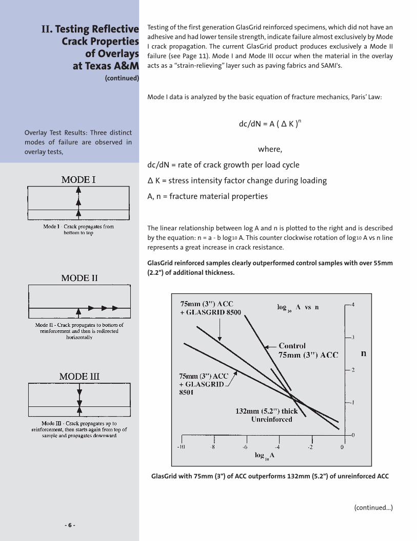
Testing of the first generation GlasGrid reinforced specimens, which did not have an
adhesive and had lower tensile strength, indicate failure almost exclusively by Mode
I crack propagation. The current GlasGrid product produces exclusively a Mode II
failure (see Page 11). Mode I and Mode III occur when the material in the overlay
acts as a “strain-relieving” layer such as paving fabrics and SAMI's.
Mode I data is analyzed by the basic equation of fracture mechanics, Paris’ Law:
dc/dN = A ( ∆ K )n
where,
dc/dN = rate of crack growth per load cycle
∆ K = stress intensity factor change during loading
A, n = fracture material properties
The linear relationship between log A and n is plotted to the right and is described
by the equation: n = a - b log10 A. This counter clockwise rotation of log10 A vs n line
represents a great increase in crack resistance.
GlasGrid reinforced samples clearly outperformed control samples with over 55mm
(2.2") of additional thickness.
GlasGrid with 75mm (3") of ACC outperforms 132mm (5.2") of unreinforced ACC
(continued...)
- 6 -
II. Testing ReflectiveCrack Properties
of Overlaysat Texas A&M
(continued)
Overlay Test Results: Three distinct
modes of failure are observed in
overlay tests,

“SIMPLE,” a computer program developed at the Texas Transportation Institute,
provides a comprehensive mechanistic method of computing the reflective cracking
life of an overlay. It remains the first and only program capable of predicting the
combined influence of traffic and thermal stresses.
Fracture properties obtained in the TTI research study have been input into
“SIMPLE” along with traffic data, temperature data, existing pavement data, and
overlay data in order to determine the design life of reinforced and unreinforced
overlays.
The resulting outputs along with field observations from hundreds of projects
worldwide have been used to establish guidelines and limitations for the use of
GlasGrid.
- 7 -
II. Testing ReflectiveCrack Propertiesof Overlaysat Texas A&M(continued)
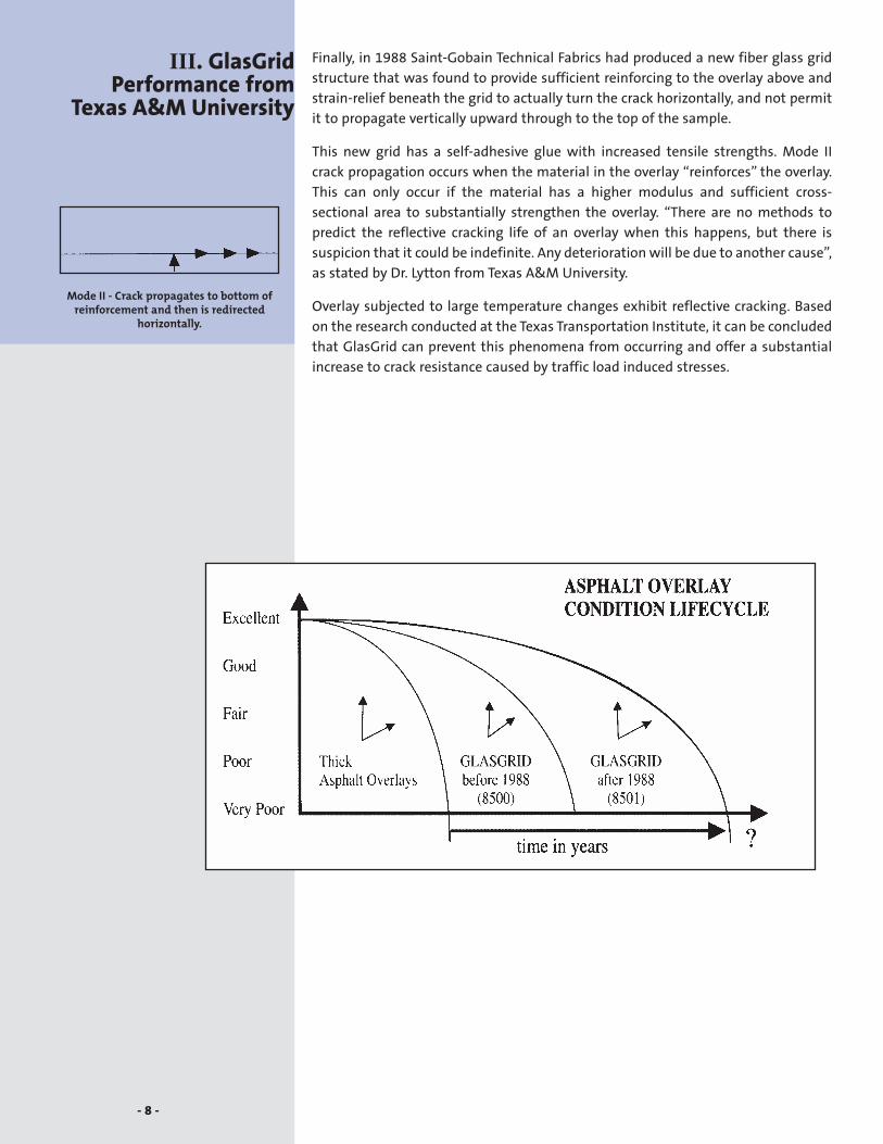
Finally, in 1988 Saint-Gobain Technical Fabrics had produced a new fiber glass grid
structure that was found to provide sufficient reinforcing to the overlay above and
strain-relief beneath the grid to actually turn the crack horizontally, and not permit
it to propagate vertically upward through to the top of the sample.
This new grid has a self-adhesive glue with increased tensile strengths. Mode II
crack propagation occurs when the material in the overlay “reinforces” the overlay.
This can only occur if the material has a higher modulus and sufficient cross-
sectional area to substantially strengthen the overlay. “There are no methods to
predict the reflective cracking life of an overlay when this happens, but there is
suspicion that it could be indefinite. Any deterioration will be due to another cause”,
as stated by Dr. Lytton from Texas A&M University.
Overlay subjected to large temperature changes exhibit reflective cracking. Based
on the research conducted at the Texas Transportation Institute, it can be concluded
that GlasGrid can prevent this phenomena from occurring and offer a substantial
increase to crack resistance caused by traffic load induced stresses.
III. GlasGridPerformance from
Texas A&M University
- 8 -
Mode II - Crack propagates to bottom ofreinforcement and then is redirected
horizontally.

History has shown that three major influences dictate the performance of asphalt
reinforcement: Material Composition, Product Geometry, and Jobsite
Constructability.
Material Composition
As with any product of quality, it is essential to begin with the proper raw
materials. Asphalt reinforcement must provide increased tensile strength at a very
low deformation. It must be compatible with the asphalt to provide a strong
internal bond within the composite. It must be thermally stable and physically
durable to withstand the rigors of the paving operation. And finally, for long term
performance, it must exhibit no creep deformation or chemical breakdown over
time.
Product Geometry
The geometric configuration of an interlayer will greatly affect its reinforcement
capability. The cross-sectional area must be sufficient so that it will redirect tensile
stresses. The width of the product must exceed the limits of the redirected stress
energy. Finally, the opening (windows) in the mesh must be such that optimum
shear adhesion is achieved while promoting aggregate interlock and confinement.
Jobsite Constructability
Practical application of any reinforcement requires the ability to adapt to any
paving operation. Placement must be quick and easy, and the product must
remain secure during paving.
GlasGrid is composed of high modulus fiber glass strands coated with modified
polymer and adhesive backing.
IV. Engineer Checklistfor Specifying OverlayReinforcement
Why Does GlasGridReinforcement RetardReflective Cracking?
HIGH TENSILE STRENGTH
LOW ELONGATION
NO LONG-TERM CREEP
CROSS-SECTIONAL AREA
ASPHALT COMPATIBILITY
THERMAL STABILITY
CHEMICAL STABILITY
PHYSICAL DURABILITY
WIDTH
SHEAR ADHESION
INTERLOCK &CONFINEMENT
QUICK INSTALLATION
- 9 -

HIGH TENSILE STRENGTH
High modulus, E, fiber glass exhibits a tremendous strength to weight ratio and is
pound for pound stronger than steel. With a modulus ratio up to 20:1 over asphalt
concrete (20°C or 68°F), GlasGrid clearly provides the stiffness required to redirect
crack energy.
LOW ELONGATION
The stress-strain diagram for glass is virtually a straight line of nearly vertical
slope. This indicates that the material is very stiff and resists deformation.
GlasGrid exhibits less than 5% elongation at break.
NO LONG-TERM CREEPMany reinforcement materials that appear to be initially stable, exhibit creep
deformation due to constant loading over long periods of time. Fiber glass exhibits
no creep. This assures long term performance.
TYPICAL ASPHALT PAVEMENT GRIDS CREEP CHARACTERISTICS
(continued...)
- 10 -
IV. Engineer Checklistfor Specifying Overlay
Reinforcement(continued)

CROSS SECTIONAL AREASufficient cross sectional “Area, A” multiplied by the “Modulus, E” of the material
( = AE ) is required to
redirect crack energy.
The research conducted
at Texas A&M shows
GlasGrid meets this
requirement.
ASPHALTCOMPATIBILITYThe specially formulated polymer coating was designed to deliver high asphalt
compatibility. Each fiber is completely coated to insure no slippage within the
composite asphalt.
THERMAL STABILITYThe melting point of fiber glass is 1000°C (1800°F). This insures stability when
subjected to the excessive heat of a paving operation.
CHEMICAL STABILITYThe specially formulated polymer coating was designed to provide protection
against a wide range of chemical attack.
PHYSICAL DURABILITYThe specially formulated polymer coating provides protection from physical
abrasion. Additionally, coated fiber glass is resistant to biological attack, UV light,
and weather.
WIDTHField trials indicate that the
reflective crack energy of a
redirected horizontal crack
can travel up to 0.6m (2 feet)
beyond its point of origin.
1.5m (five foot) wide patch
reinforcement (style #8502)
helps insure complete
dissipation on either side of
the crack. Lesser widths
have shown horizontal
propagation to turn vertically
upward at the reinforcement
limits resulting in a lesser
crack on each side of the interlayer.
SHEAR ADHESIONThe specially formulated polymer coating provides GlasGrid reinforced overlays
with sufficient adhesion to maintain a good bond between asphalt concrete
overlays.
(continued...)
- 11 -
IV. Engineer Checklistfor Specifying OverlayReinforcement(continued)

INTERLOCK & CONFINEMENTAsphalt concrete gains its compressive strength through compaction. The mix
aggregate is specifically selected to provide interlock and confinement within the
load bearing stone structure, and asphalt cement (AC) is the glue that holds the
particles together.
The quality of both the aggregate and the AC will determine the quality of the final
pavement structure.
As particles strike through the GlasGrid structure, they become mechanically
interlocked within the composite system. This confinement zone impedes particle
movement. Asphalt mixtures can achieve better compaction, greater bearing
capacity, and increased load transfer with less deformation. Testing indicates that
the 12.5mm x 12.5mm (1/2" x 1/2") window is optimum for most surface mixes.
EASY INSTALLATIONGlasGrid with its unique adhesive allows quick and easy installation. The product
can be rolled out mechanically with SGTF's special placement tractor or manually
from the back of a pick up truck. Placement procedures are outlined in detail in the
GlasGrid “Installation Guide”.
GlasGrid Improves Interlock and Confinement
- 12 -
IV. Engineer Checklistfor Specifying Overlay
Reinforcement(continued)

GENERAL DESIGN CONSIDERATIONS:
Site SelectionCare must be taken when selecting a site for the potential use of GlasGrid. The
existing pavement section must show no signs of pumping, excessive movement, or
structural instability. To maximize the benefit of GlasGrid, pavements must be
structurally sound. If a pavement is structurally unstable, the Engineer should
design to first address the structural problem, then the reflective cracking problem.
Pavement EvaluationField evaluation should include a visual distress survey in accordance with a
Pavement Condition Index (PCI) methodology and deflection testing, such as a
falling weight deflectometer (FWD). This data should be used to determine the
effective modulus of the existing pavement section. Slab replacement, mud jacking,
full depth asphalt replacement, and pot hole repairs shall be made prior to the
placement of the overlay, as determined by an Engineer.
Crack SealingAll existing pavement cracks should be sealed by conventional methods. Cracks
greater than 6mm (1/4") should be filled with a suitable crack filler.
Levelling CourseGlasGrid performs best on a levelling course and must be placed on a smooth, level,
asphaltic surface. A minimum 19mm (3/4") levelling course of asphalt must be
placed on concrete surfaces without an existing overlay. Crack areas exhibiting
excessive surface irregularities such as faulting shall also be levelled. Slab joints
exhibiting upward tenting must be saw cut to relieve pressure prior to levelling.
Minimum Depth of OverlayGlasGrid requires a minimum overlay thickness of 40mm (1.5"). The procedures
outlined in the GlasGrid “Installation Procedures” shall be strictly followed.
Tack Coats are optional with GlasGrid. Local conditions or specifications may require
a tack coat to be used.
GlasGrid is suitable for most pavement sections. Pavements with a high potential
for slippage must be carefully evaluated to determine suitability.
Always remember ... “If there is poor load transfer across the crack, no
reinforcement will help!”, as stated by Dr. Lytton at Texas A&M University.
- 13 -
V. GlasGrid ReinforcedOverlay DesignGuidelines &Limitations

1. DESCRIPTION:Work shall consist of furnishing and placing a high strength open fiber glass mesh
grid between pavement layers for the purpose of incorporating a reinforcing grid
within the pavement structures. The specification guide is applicable to high
strength modulus reinforcing grids for full width coverage of the pavement.
2. MATERIAL SPECIFICATION: GlasGrid 8501The material with this specification shall be constructed of fiber glass yarns knitted
in a stable construction that conforms to the following properties when tested by
the appropriate test method.
Tensile Strength kN/m lb./in
Component strand strengths 100 560
Test Method G.R.I. GG 1-87 or ASTM D 6637
Elongation at Break Percent Percent
Maximum 5 5
Test Method G.R.I. GG 1-87 or ASTM D 6637
Melting Point Celsius Fahrenheit
Minimum 218 425
Test Method ASTM D 276
Mass/Unit Area g/m2 oz/yd2
Test Method D 5261-92 370 11
All values represent certifiable average minimum roll values in the weakest
principal direction of the grid. Manufacturer must supply test data prior to the start
of grid placement to the Engineer. Data must be signed by the quality assurance
principal at the manufacturing facilities and be representative of all product on the
project.
3. STORAGE:Reinforcement Grid must be stored as per manufacturer recommendations in a dry
covered condition free from dust, dirt and moisture.
4. PAVEMENT PREPARATION: Surface must be prepared as a clean, dry, even surface with pavement cracks sealed.
a. Cracks between 3mm (1/8") and 6mm (1/4") should be filled with a suitablecrack filler. Wider cracked surfaces need to be addressed with a method thatprovides a level surface. Any holes need to be filled with hot mix. Unevensurfaces and extensive cracking shall use a levelling course preferably with adense graded mix of a minimum average thickness of 19mm (3/4").
b. On milled surfaces the following surface treatment shall be carried out:
1. A minimum 19mm (3/4") asphalt concrete levelling course shall be applied tothe milled surface prior to placing the glass mesh.
2. The surface temperature before laying the grid shall be between 5°C (40°F)and 60°C (140°F).
(continued...)
- 14 -
VI. Special ContractProvisions for
GlasGrid

c. Prior to placing grid, the existing pavement shall be cleaned and providesignificant adhesion to the grid to the satisfaction of the Engineer. Pavementshall be cleaned by a mechanical device by sweeping or vacuuming and be freeof oil, vegetation, sand, dirt, water, gravel, and other debris.
5. CONSTRUCTIONa. Tack coats are optional. If local conditions require a tack coat to be used, the grid
manufacturer shall recommend a tack coat rate that will provide properadhesion.
b. The grid shall be laid out by mechanical means or by hand under sufficienttension to eliminate ripples. Should ripples occur, these must be removed bypulling the grid tight or in extreme cases (on tight radii), by cutting and layingflat.
c. Transverse joints must be lapped in the direction of the paver 75 - 150mm (3" - 6"). Longitudinal joints must be 25 - 50mm (1" - 2") overlapped.
d. The surface of the grid shall be rolled with a rubber coated roller, or pneumatictire roller, to activate the adhesive. Tires must be clean to avoid pick up of thegrid.
e. Construction and emergency traffic may run on grid after being rolled. However,it must be ensured that damage is not caused to the grid by vehicles turning orbraking etc., and that the mesh must be kept clean of mud, dust and otherdebris. Damaged sections shall be removed and patched, taking care tocompletely cover the damaged area.
f. The contract price per square yard/square meter for the reinforcing grid shallinclude full compensation for furnishing all labor, materials, tools, equipmentand incidentals involved in furnishing and placing the grid completely in place,as shown on the plans required by these special provisions and as directed bythe Engineer.
6. TESTS FOR PROPER ADHESION1. Cut approx. 1m2 (1 sq. yd.) of grid.
2. Place on area to be paved.
3. Activate self-adhesive glue by rolling with a rubber tired roller or by walking onthe sample.
4. Insert hook of spring balance under center of grid piece.
5. Pull upwards until grid starts to pull from the surface.
6. Record results in kg. or lb.
7. If approx. 5 kg (11 lbs) or more, OK to pave. Stop immediately if grid moves orripples. IF LESS THAN 5 KG (11 LBS) - DO NOT PAVE DUE TO POOR ADHESION.
- 15 -
VI. Special ContractProvisions forGlasGrid(continued)

- 16 -
VII. Typical DesignCross Section
(continued)
GlasGrid 8502 Detailed Repair SystemPortland Cement Concrete Pavement

- 17 -
VII. Typical DesignCross Section(continued)
GlasGrid 8502 Detailed Repair SystemAsphalt Concrete Pavement

- 18 -
VII. Typical DesignCross Section
(continued)
GlasGrid 8501 Complete Road SystemMilled Pavement

- 19 -
VII. Typical DesignCross Section(continued)
GlasGrid 8501 Complete Road SystemPortland Cement Concrete Pavement
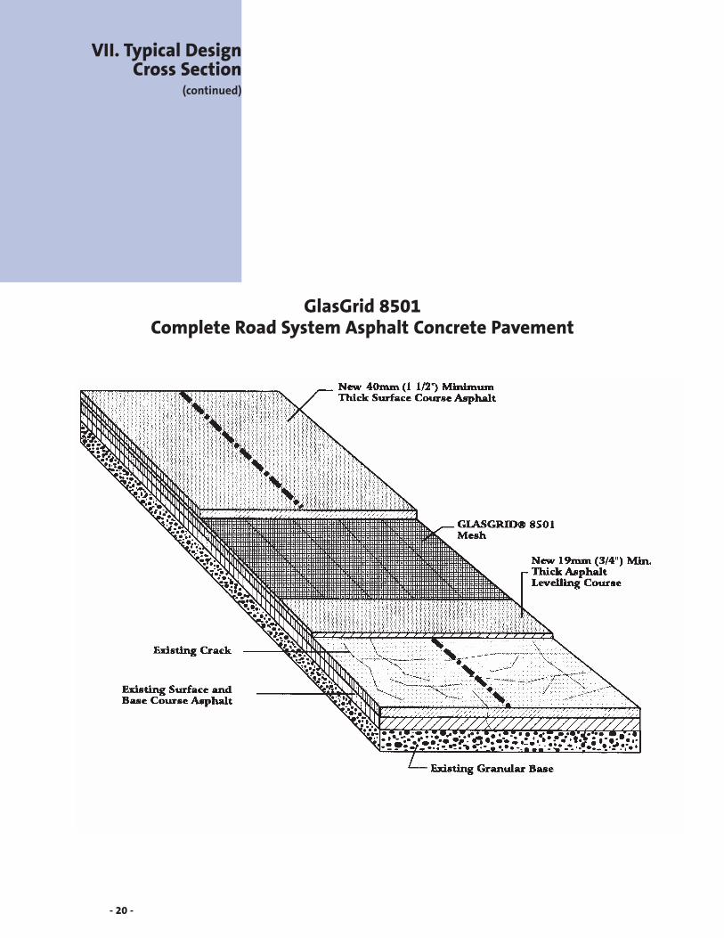
GlasGrid 8501Complete Road System Asphalt Concrete Pavement
- 20 -
VII. Typical DesignCross Section
(continued)

- 21 -

Saint-Gobain Technical Fabrics
Email: [email protected]
Websites: www.sgtf.com www.glasgrid.com
GlasGrid is manufactured at an ISO 9002-1994registered facility of Saint-Gobain Technical Fabrics®GlasGrid is the registered trademark of Saint-Gobain Technical Fabrics. U.S. Patent 4699542/4957390/5110627/5393559. Canadian Patent 1240873.European Patent EP0318707. Japanese Patent 2611064. ©2002 Saint-Gobain Technical Fabrics 09/02 1338