Embed Size (px)
Citation preview
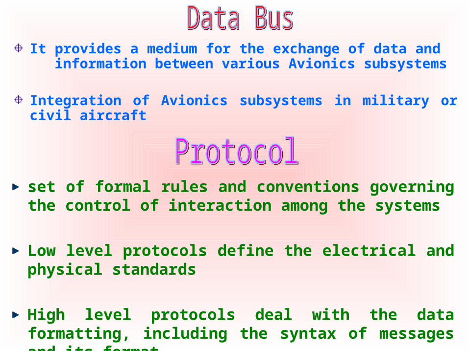
It provides a medium for the exchange of data and information between various Avionics subsystems
Integration of Avionics subsystems in military or civil aircraft
set of formal rules and conventions governing the control of interaction among the systems
Low level protocols define the electrical and physical standards
High level protocols deal with the data formatting, including the syntax of messages and its format
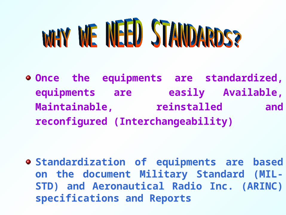
Once the equipments are standardized,
equipments are easily Available, Maintainable,
reinstalled and reconfigured (Interchangeability)
Standardization of equipments are based on the document Military Standard (MIL-STD) and Aeronautical Radio Inc. (ARINC) specifications and Reports
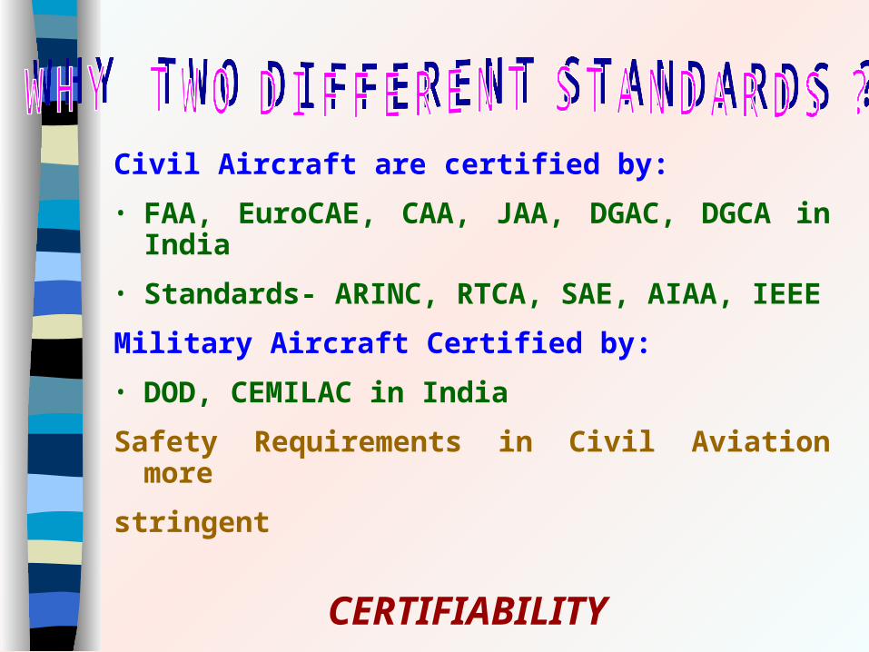
Civil Aircraft are certified by:
• FAA, EuroCAE, CAA, JAA, DGAC, DGCA in India
• Standards- ARINC, RTCA, SAE, AIAA, IEEE
Military Aircraft Certified by:
• DOD, CEMILAC in India
Safety Requirements in Civil Aviation more
stringent
CERTIFIABILITY

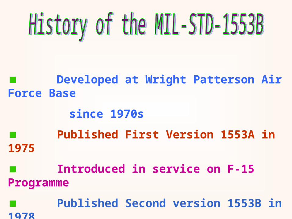
Developed at Wright Patterson Air Force Base
since 1970s
Published First Version 1553A in 1975
Introduced in service on F-15 Programme
Published Second version 1553B in 1978

MIL-STD-1553, Aircraft Internal Time Division Command /
Response Multiplex Data Bus, is a Military standard
(presently in revision B), which has become one of the
basic tools being used today for integration of Avionics
subsystems
The standard describes the method of communication
and the electrical interface requirements for the subsystems
connected in the data bus
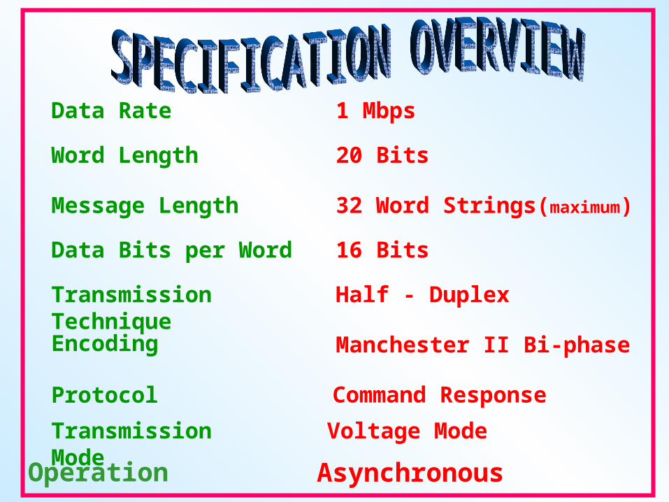
Data Rate
Message Length
Data Bits per Word
Transmission Technique
Encoding
Protocol
1 Mbps
32 Word Strings(maximum)
16 Bits
Half - Duplex
Manchester II Bi-phase
Transmission Mode
Word Length 20 Bits
Voltage Mode
Command Response
Operation Asynchronous

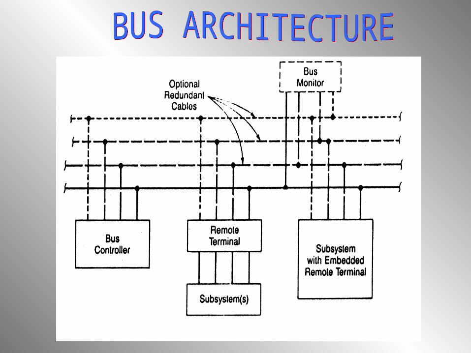
BUS CONTROLLER (BC)
STAND-ALONE REMOTE TERMINAL (SRT)
EMBEDDED REMOTE TERMINAL (ERT)
MONITORING TERMINAL (MT)
TRANSMISSION MEDIA


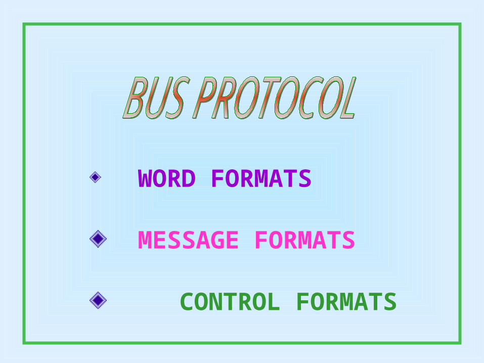
WORD FORMATS
MESSAGE FORMATS
CONTROL FORMATS
COMMAND WORD
DATA WORD
STATUS WORD

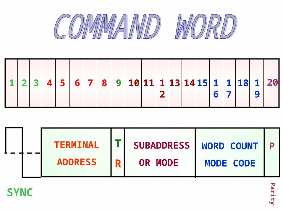
SYNC
19181716151413121110987654321 20
TERMINAL
ADDRESS
T
R
SUBADDRESS
OR MODE
WORD COUNT
MODE CODE
P
Parity

19181716151413121110987654321 20
P
Parity
16 BIT DATA
SYNC
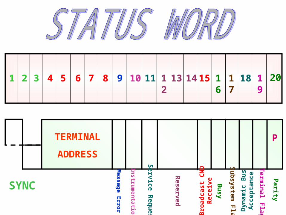
19181716151413121110987654321 20
TERMINAL
ADDRESS
P
SYNC
Message E
rror
Instru
men
tation
Service R
equ
est
Res erv ed
Broad
cast CM
D
Recei ve
Bu
sy
Su
bsystem
Flag
Dyn
amic B
us
Accep
tance
Ter m
inal F
la g
Parity
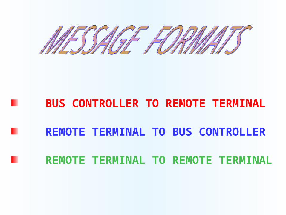
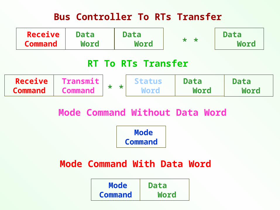
BUS CONTROLLER TO REMOTE TERMINAL
REMOTE TERMINAL TO BUS CONTROLLER
REMOTE TERMINAL TO REMOTE TERMINAL

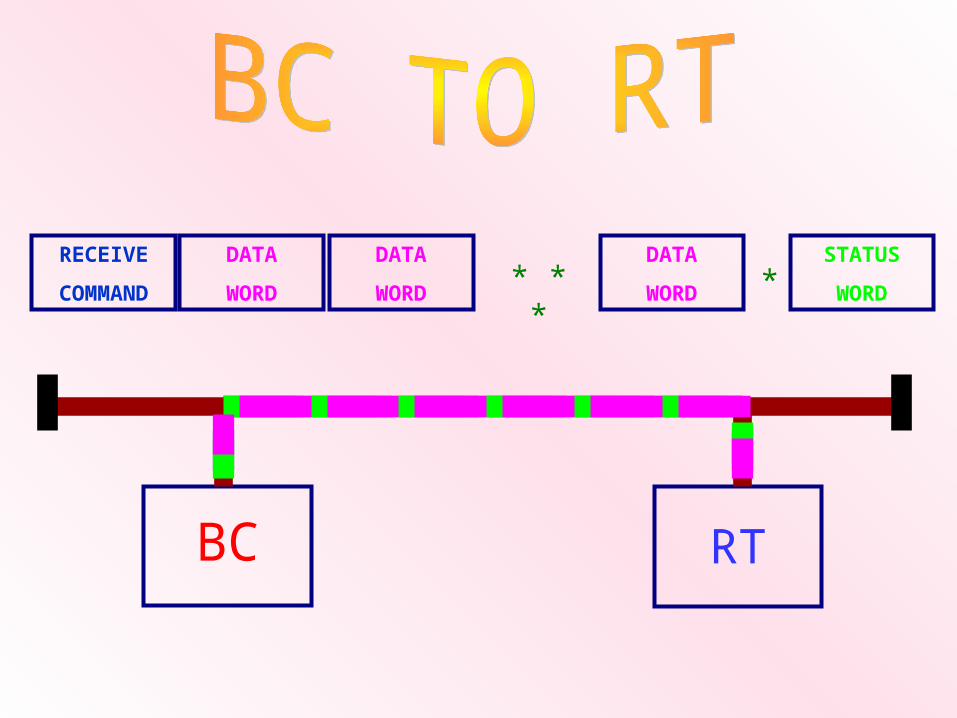
RECEIVE
COMMAND
DATA
WORD
DATA
WORD
DATA
WORD
STATUS
WORD* * * *
BC RT
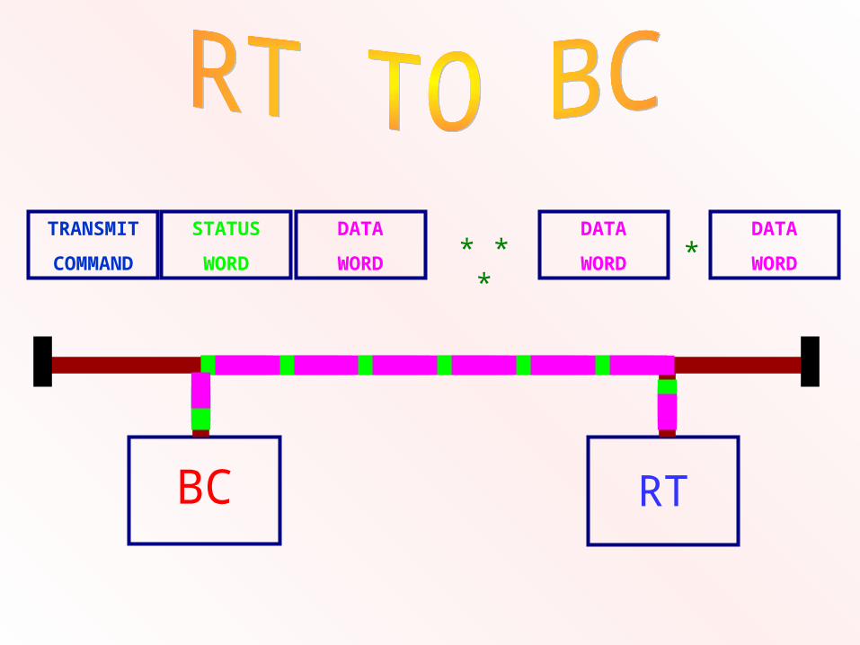
TRANSMIT
COMMAND
STATUS
WORD
DATA
WORD
DATA
WORD
DATA
WORD* * * *
BC RT
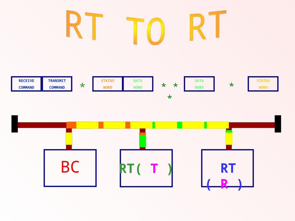
* * * *
BC RT ( R )
RECEIVE
COMMAND
TRANSMIT
COMMAND
STATUS
WORD
DATA
WORD
DATA
WORD
STATUS
WORD
RT( T )
*
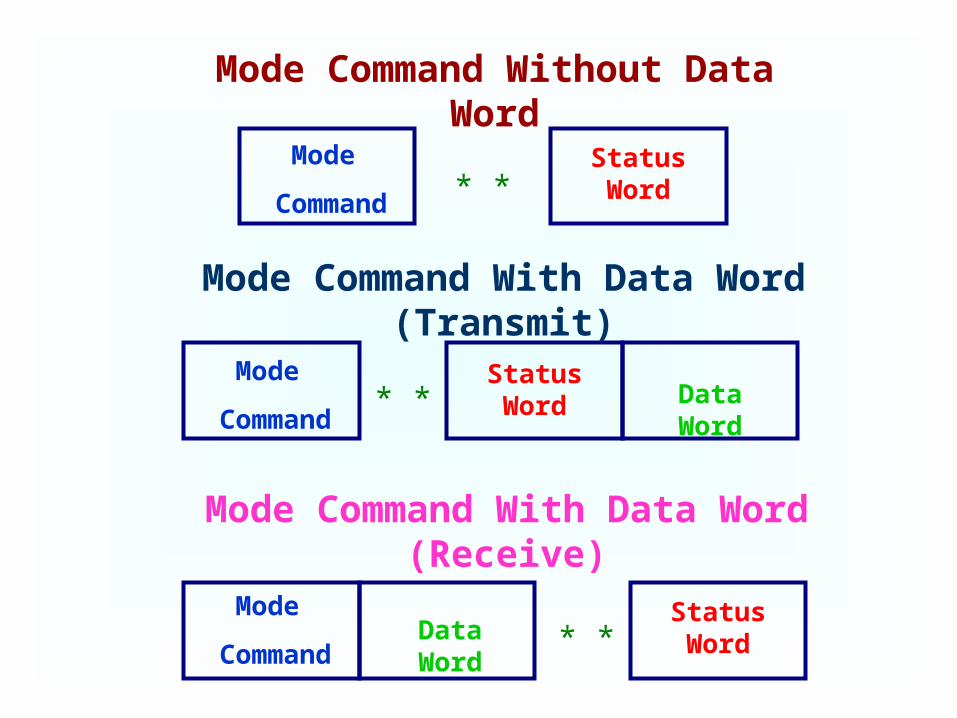
Mode
Command
Mode
Command
Mode
Command
Status Word
Status Word
Status Word
Data Word
Data Word
Mode Command Without Data Word
Mode Command With Data Word (Transmit)
Mode Command With Data Word (Receive)
* *
* *
* *
Receive Command
Data Word
Data Word
Receive Command
Mode Command
Mode Command
Transmit Command
Status Word
Data Word
Data Word
Data Word
* *
* *
Data Word
Bus Controller To RTs Transfer
RT To RTs Transfer
Mode Command Without Data Word
Mode Command With Data Word

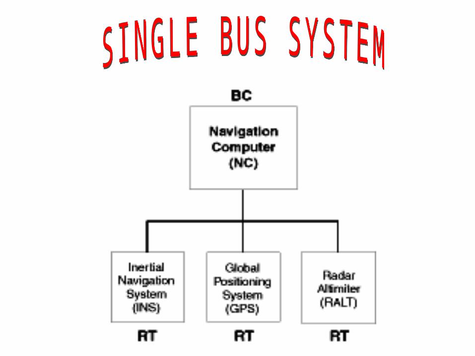
SINGLE BUS SYSTEM
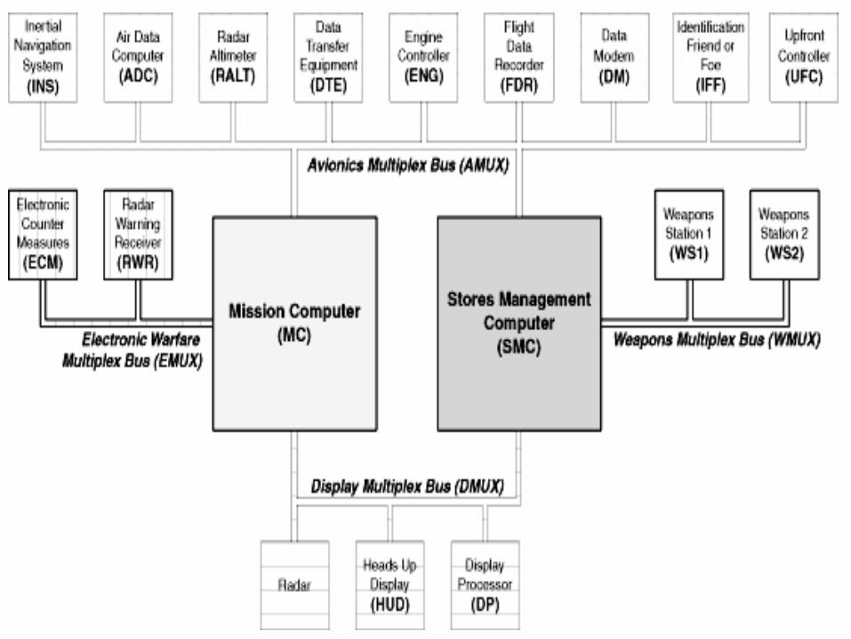
MULTIPLE BUS SYSTEM


Pseudo Time Slot
Polled Sequence Operation
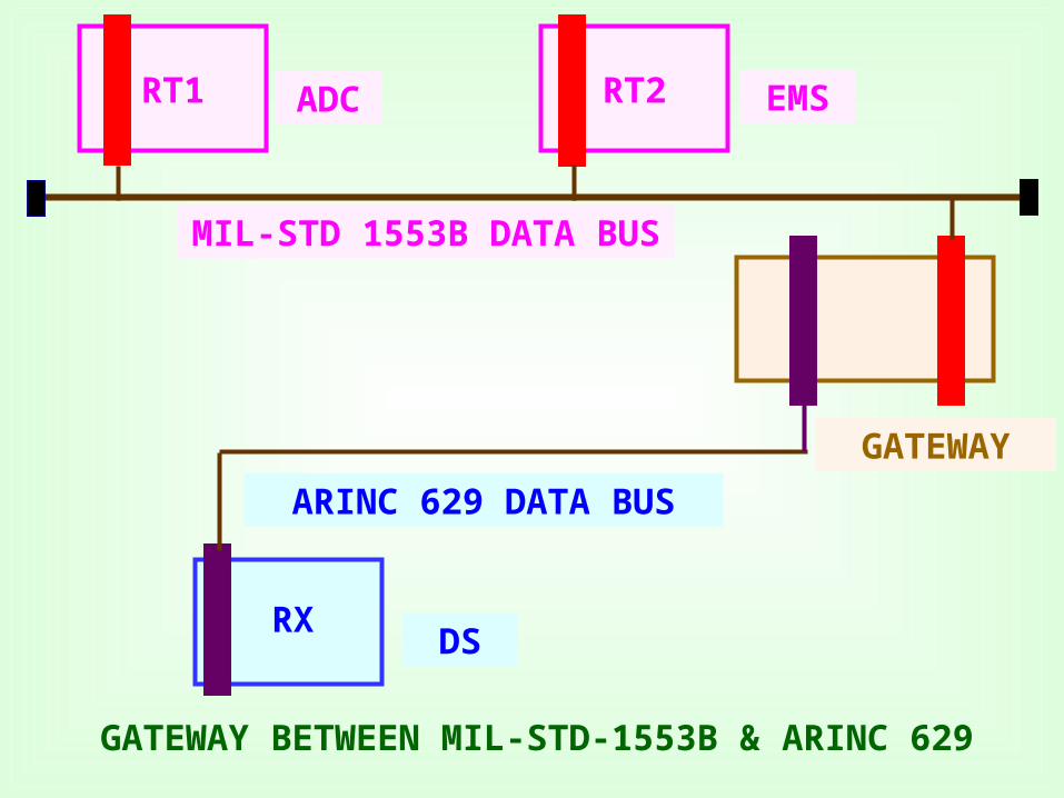
RT1 RT2
MIL-STD 1553B DATA BUS
ARINC 629 DATA BUS
ADC EMS
RXDS
GATEWAY
GATEWAY BETWEEN MIL-STD-1553B & ARINC 629