Embed Size (px)
DESCRIPTION
http://www.iosrjournals.org/iosr-jeee/pages/v8i1.html
Citation preview

IOSR Journal of Electrical and Electronics Engineering (IOSR-JEEE)
e-ISSN: 2278-1676,p-ISSN: 2320-3331, Volume 8, Issue 1 (Nov. - Dec. 2013), PP 101-110
www.iosrjournals.org
www.iosrjournals.org 101 | Page
Control of Grid- Interfacing Inverters with Integrated Voltage
Unbalance Correction
Mohan.A, D.Nagaraju
Abstract: The control of a grid interfacing inverter with integrated voltage unbalance correction. It is
proposed to add an additional function to the inverter to decrease the negative-sequence voltage at the point
of connection with the utility grid. Based on symmetric sequence voltage decomposition and using an
improved multi-variable filter, the grid-interfacing inverter intentionally absorbs a small amount of negative-
sequence current from the grid, thereby helping to correct the negative-sequence voltage. Although the
amplitude reduction contributed by each individual inverter system is small compared to the total negative-
sequence component, grid interfacing inverter modules can collectively achieve substantial results in the grid.
The integrated function and proposed control has been verified in simulations and by experiments on a
laboratory prototype.
I. Introduction: The voltage unbalance correction function is added, which intentionally regulates negative sequence
currents. Note that, in order to obtain a maximum power factor, most grid-interfacing inverters deliver only
positive-sequence currents under either balanced or unbalanced conditions. Therefore, the development of this
proposed controller differs from the conventional
one, and its design will be presented in the next sections of this paper.
In view of unbalanced with the theory of symmetric decomposition for three phase systems,
unbalanced grid voltages can be divided into three groups, namely positive, negative, and zero sequence
voltages. Similarly, current quantities can also be separated. By disregarding the mutual coupling between the
grid lines in an equivalent circuit model for each group of sequence components can be derived. The diagram
for negative-sequence components is shown in Fig. 2, where the superscript “-” denotes negative sequence.
Figure shows the structure of a three-phase four-wire grid-interfacing system being connected to the
utility grid at the POC through LCL filters. It normally synchronizes with the utility grid and delivers electrical
energy to the grid from the DC-bus when pre-regulated distributed sources are connected.
Similarly, the superscript “+” denotes positive sequence. Phasors Vg and V− s (in the following,
complex numbers are denoted with a bar subscript) are the negative-sequence voltages of the utility grid and at
the PoC, respectively.Current I − s is the negative-sequence current controlled by the grid-interfacing inverter.
The equivalent line impedance is represented by Zg, the equivalent impedance of the utility grid when the line
impedances of the three phases are assumed symmetrical.
Fig:1(a): 3-ɸ four wire Grid interfacing inverter at PoC

Control Of Grid- Interfacing Inverters With Integrated Voltage Unbalance Correction
www.iosrjournals.org 102 | Page
Fig 1(b): Negative sequence equivalent model
Fig .1(c):Pharos diagram of the Negative sequence model
Accordingly, a phasor diagram showing the change for negative-sequence fundamental current is
drawn . By changing the amplitude and phase of the negative sequence current I − s , the negative-sequence
voltage V− s can be regulated through the voltage drops across the line impedance. For a given amplitude I − s
, the voltage changes along the dashed circle and reaches a minimum value at the point M where θ− (the phase
angle between negative sequence voltage and current) equals the negative of impedance angle of Zg’s.
Similarly, zero-sequence voltages at the PoC can be compensated by regulating the zero-sequence
currents within the system.
This paper only concentrates on the correction of negative-sequence voltages, considering zero-
sequence voltages do not exist in case of three wire systems. Of course, zero-sequence voltages can be isolated
by transformers when needed.
Furthermore, it is noted that measurements of zero-sequence components can be done simply by
adding three-phase quantities, M while accurate positive- and negative-sequence components are difficult to be
determined.
Therefore, zero sequence voltage correction can be trivially added to the control based on the proposed
control scheme for negative-sequence voltage correction and is not discussed in this paper.
II. Control Scheme 2.1 DETERMINATION OF NEGATIVE-SEQUENCE CURRENTS
The basic principle of how to correct unbalanced voltage at the PoC with sequence-current control. It
is suggested to determine the negative-sequence currents based on the voltage unbalance factor. To assess
unbalanced voltages at the PoC, the voltage unbalance factor, KVUF is defined as the ratio between the
amplitude of the negative-sequence voltage V− s and the amplitude of the positive-sequence voltage V+ s . The
following constraint equation is proposed to calculate the desired current amplitude I −s :
Where I+ s is the amplitude of the positive-sequence current. Then, the resulting I − s is derived based on the
ratio of unbalance voltages at the PoC from (1). However, the voltage unbalance factor at the PoC varies with
the controlled negative-sequence currents, because the controller utilizes feed forward measurements of KVUF
and operates in a open-loop. Consequently, this strategy may cause the value of KVUF in (1) to vary.
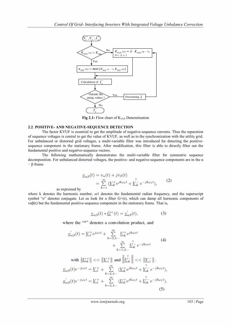
To ensure a stable correction, a smooth update method for KVUF is added to the control. The flow
chart shown in Fig. 4 illustrates how to derive the final I − s . The currently measured quantity is referred to as
KVUF(n), and the previous one is KVUF(n − 1 ). In Fig. 4, the minimum threshold (Kmin) of negative-
sequence correction is defined according to practical demands, anda coefficient denoted by λ is introduced for
smooth regulation when decreasing the output value of KVUF. Note that, for system protection, the current
rating of the inverters is always checked before returning I − s .
Control Of Grid- Interfacing Inverters With Integrated Voltage Unbalance Correction
www.iosrjournals.org 103 | Page
Fig 2.1: Flow chart of KVUF Determination
2.2. POSITIVE- AND NEGATIVE-SEQUENCE DETECTION
The factor KVUF is essential to get the amplitude of negative-sequence currents. Thus the separation
of sequence voltages is central to get the value of KVUF, as well as to the synchronization with the utility grid.
For unbalanced or distorted grid voltages, a multi-variable filter was introduced for detecting the positive-
sequence component in the stationary frame. After modification, this filter is able to directly filter out the
fundamental positive and negative-sequence vectors.
The following mathematically demonstrates the multi-variable filter for symmetric sequence
decomposition. For unbalanced distorted voltages, the positive- and negative-sequence components are in the α
− β frame
as expressed by
where k denotes the harmonic number, ω1 denotes the fundamental radian frequency, and the superscript
symbol “o” denotes conjugate. Let us look for a filter G+(t), which can damp all harmonic components of
vαβ(t) but the fundamental positive-sequence component in the stationary frame. That is,

Control Of Grid- Interfacing Inverters With Integrated Voltage Unbalance Correction
www.iosrjournals.org 104 | Page
Fig 3: Implementation diagram of the multi variable filter

Control Of Grid- Interfacing Inverters With Integrated Voltage Unbalance Correction
www.iosrjournals.org 105 | Page
Therefore, the detection for v+ α1(t)+jv+ β1(t) and v− α1(t)−jv−β1(t) are approximately achieved
from (13) and (17). These equations can be easily implemented in the α− β frame by digital control, without
complicated transformation to the SRF and the inverse transformation.
In practical applications, the negative-sequence component is too small to be detected accurately. This
is because the input signals involve a large proportion of positive sequence components which are difficult to
damp totally. Alternative signals _vαβ(t), with
where the dominant positive-sequence component v+ αβ1 (t) = v+ α1(t)+jv+ β1(t) is abstracted, and
can be used as input signals. This will improve the filtering effect for negative-sequence quantities. Fig. 5
illustrates the implementation diagram of the multiple-variable filter, where the bandwidth ωb for the positive-
and negative-sequence filter is denoted by ωb1 and ωb2 respectively (the values can be different and adapted to
practical situations). The central frequency ω1 is set at the fundamental frequency of the grid voltage. In case
of grid frequency variations the bandwidth can be increased slightly, or ω1 can be adaptively updated with the
measured fundamental frequency.
A frequency domain multi-variable filter plot is drawn based on (10) and the second equation in (16).
Due to unity gain and zero phase-shift of the positive-sequence filter at the central frequency (50Hz), vαβ(t) +
jvβ(t) can be directly derived. This manipulation is equivalent to a notch filter at the positive fundamental
frequency, as shown in Figure
Fig 4:Multi variable filter plot in frequency domain with w1=314rad/s; and wb1=wb2=20
III. Reference Signals Generation Figure shows the block diagram of the inverter’s current reference generator. It consists of the
detection of symmetric sequence voltages with a multi-variable filter, the VUF calculation, average power
regulation and the signal synthesis. The first two processes have been detailed in the previous two subsections.

Control Of Grid- Interfacing Inverters With Integrated Voltage Unbalance Correction
www.iosrjournals.org 106 | Page
By utilizing the fundamental positive- and negative-sequence components filtered out by the filter, we can
obtain
Where V+mag and V −mag denote the magnitude of fundamental positive- and negative-sequence voltage,
respectively.
Fig 3.1:Current reference generation for the inverter control
Consequently, two groups of per-unit signals can be derived with divisions, that is i+ α + ji+ β and
i−∗ α +ji−∗ β ,According to the principle described in section II, negative-sequence currents are designed to
keep a phase-shift θ− with the negative-sequence voltage. This phase-shift equals the negative line impedance
angle for the maximum correction effect. Its mathematical derivation is
The positive-sequence current references are either in phase or in anti-phase with the positive-
sequence component of the grid voltage, depending on the desired direction for energy delivery. In this paper,
the gain Kdir is set −1 in order to deliver energy to the utility grid.
In the average power control loop of figure the power reference Pis given, which can be determined
according to the application, such as the active power generated by upstream DG or the power demanded by
the downstream utility grid.
In order to eliminate the effects of double fundamental frequency ripple on the measured average
power, the parameters should have a small proportional gain and a big integration time constant. In this work,
the gain is chosen as 0.04 and the time constant is 0.02s. The output of the PI controller is used to regulate the
amplitudes of the desired currents with the coefficient Kc. All together, it follows that the current references
i*sαand i*sβ are derived in the stationary frame. This is beneficial for the controller design, since the
controller presented in the next section is also designed in the stationary frame. The mathematical
manipulations to optimally implement the above digital process are not the subject of this paper, and will be
discussed elsewhere.
IV. Controller for Currentregulation It is constructed by a double-loop current controller, that is an outer control loop with proportional-
resonant (PR) controllers for eliminating the zero steady-state error of the delivered currents, and an inner
capacitor current control loop with simple proportional controllers to improve stability. Figure shows the
controller structure of the grid interfacing inverter

Control Of Grid- Interfacing Inverters With Integrated Voltage Unbalance Correction
www.iosrjournals.org 107 | Page
Fig 4.1: Structure of the controller for current regulation
Instead of direct sampling, capacitor currents are calculated from the output currents and the inner
filter inductor currents. These currents are measured anyway for over-current protection. To eliminate the zero-
sequence currents in unbalanced situations, the current reference i*sγ should be zero.
The control for both positive- and negative-sequence components would be much too complicated and
computation-time consuming when conventional PI control with coordinate transformation were used.
Therefore, it is preferred to choose a PR controller in the stationary frame. A quasi-proportional-
resonant controller with high gain at the fundamental frequency is used, where Kpis the proportional gain, Kr
the resonant gain, and ωbrthe equivalent bandwidth of the resonant controller. A detailed design for the PR
controller has been presented in, it is not duplicated here. Through optimizing, the parameters used in the
simulation and experiment are Kp=0.5, Kr=50, and ωbr=20
V. Results: Three-phase four wire grid-interfacing inverter at POC.

Control Of Grid- Interfacing Inverters With Integrated Voltage Unbalance Correction
www.iosrjournals.org 108 | Page
Fig (a): unbalanced grid voltages in a-b-c frame
Fig (b):The per unit positive –sequence currents in phase with the positive sequence voltage
Fig (c):The negative sequence currents lags the negative sequence voltage by 45 ͦin the α-β frames

Control Of Grid- Interfacing Inverters With Integrated Voltage Unbalance Correction
www.iosrjournals.org 109 | Page
Fig (d): Experimental results of the grid-interfacing inverter with integrated voltage unbalance correction (a)
unbalanced grid voltages,(b) currents delivered by the inverter, and (c) voltages at the PoC.
Fig (e):Experimental waveforms of positive- and negative-sequence voltage detection, where the filtered out
fundamental symmetric sequence voltages are derived in the α − β frame.
Fig (f): Experimental results of the negative-sequence voltage correction. The α, β components of the negative-
sequence voltage of the PoCshow a 10% amplitude reduction compared with the negativesequence voltage of
the grid

Control Of Grid- Interfacing Inverters With Integrated Voltage Unbalance Correction
www.iosrjournals.org 110 | Page
Fig (g):Experimental waveforms of the negative-sequence voltagecorrection. The resulting corrected voltages
tend to be balanced.
References: [1] Annette von Jouanne and Basudeb (Ben) Banerjee, “Assessment of voltage unbalance,” IEEE Trans. Power Del., vol. 16, no. 4, pp.
782-790, Oct. 2001.
[2] Hideaki Fujita, and H. Akagi,“Voltage-regulation performance of a shunt active filter intended for installation on a power distribution
system,”IEEE Trans. Power Electron., vol 22, no. 3, pp. 1046-1053, May 2007.
[3] Kuang Li, Jinjun Liu, and Zhaoan Wang, and Biao Wei,“Strategies and operating point optimization of STATCOM control for voltage
unbalance mitigation in three-phase three-wire systems,”IEEE Trans. Power Del., vol. 22, no. 1, pp. 413-422, Jan. 2007.
[4] Kalyan K. Sen, “SSSC-static synchronous series compensator theory, modeling, and application,” IEEE Trans. Power Del., vol. 13, no.
1, pp. 241-246, Jan. 1998.
[5] Vijay B. Bhavaraju and Prasad N. Enjeti, “An active line conditioner to balance voltages in a three-phase system,”IEEE Trans. Ind.
Applicat., vol. 32, no. 2, pp. 287-292, Mar./Apr. 1996.
[6] Hideaki Fujita, H. Akagi, “The unified power quality conditioner: the integration of series- and shunt-active filters,” IEEE Trans. Power
Electron., vol.13, no. 2, pp. 315-322, Mar. 1998.
[7] DusanGraovac, V. A. Katic, and A. Rufer, “ Power quality problems compensation with universal power quality conditioning system,”
IEEE Trans. Power Del. , vol. 22, no. 2, pp. 968-976, Apr. 2007.
[8] Koen J. P. Macken, KoenVanthournout, Jeroen Van den Keybus, Geert Deconinck, and Ronnie J. M. Belmans, “Distributed Control of
Renewable Generation Units With Integrated Active Filter,” IEEE Trans. Power Electron., vol. 19, no. 5, pp. 1353-1360, Sep. 2004.
A.MOHAN:Studying M-Tech in power electronics at
Sri Venkateshwara Engineering College ,Suryapet his interested in Power Electronics, Power
Systems and non conventional energy sysems
D.NAGARAJU: Working as a Sr. Assistant Professor at
Sri Venkateshwara Engineering College ,Suryapet his interested in Power Electronics,
Power Systems and non conventional energy sysems