Embed Size (px)
Citation preview
177
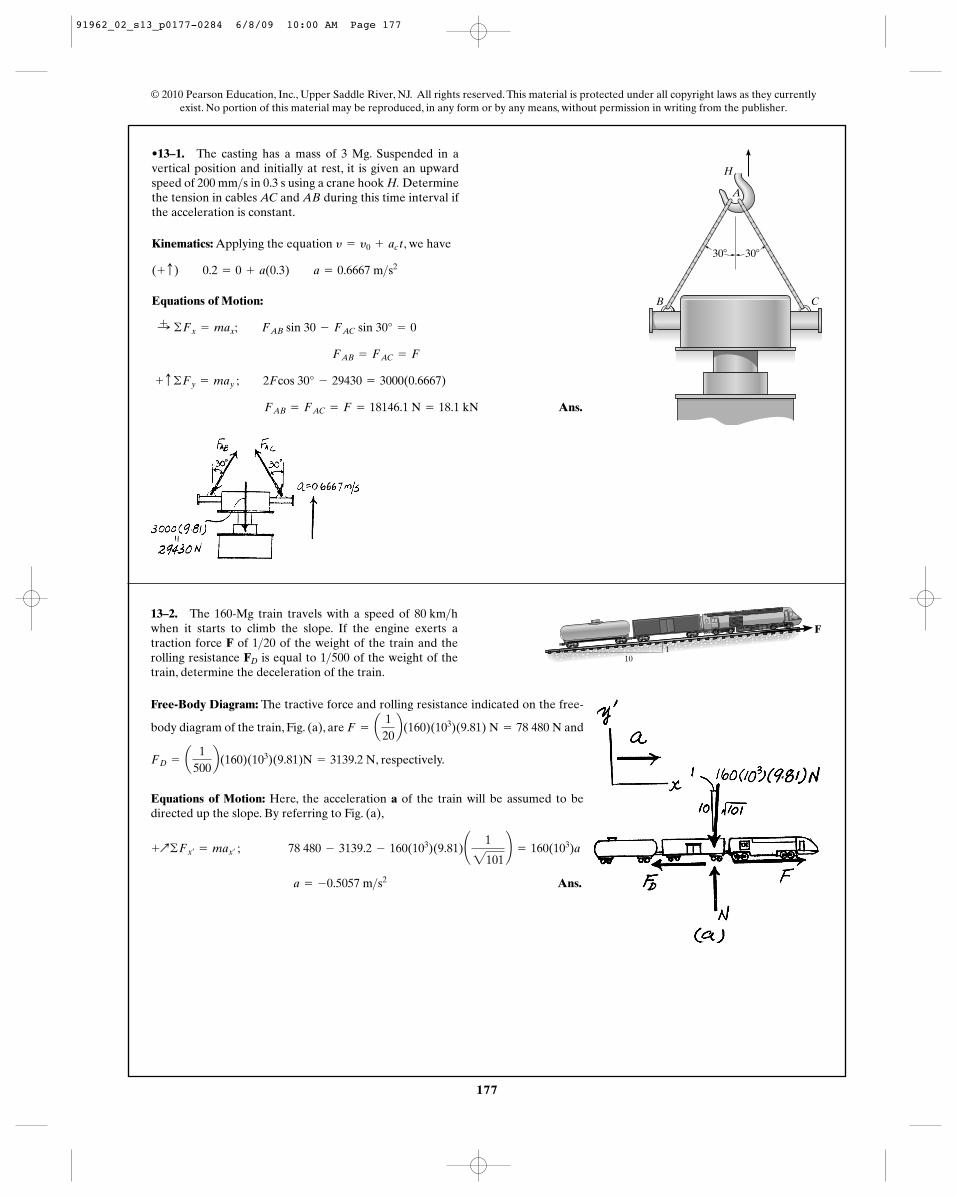
•13–1. The casting has a mass of 3 Mg. Suspended in avertical position and initially at rest, it is given an upwardspeed of 200 mm s in 0.3 s using a crane hook H. Determinethe tension in cables AC and AB during this time interval ifthe acceleration is constant.
>
Kinematics: Applying the equation , we have
Equations of Motion:
Ans. FAB = FAC = F = 18146.1 N = 18.1 kN
+ c ©Fy = may ; 2Fcos 30° - 29430 = 3000(0.6667)
FAB = FAC = F
:+ ©Fx = max; FAB sin 30 - FAC sin 30° = 0
(+ c) 0.2 = 0 + a(0.3) a = 0.6667 m>s2
y = y0 + ac t
© 2010 Pearson Education, Inc., Upper Saddle River, NJ. All rights reserved. This material is protected under all copyright laws as they currentlyexist. No portion of this material may be reproduced, in any form or by any means, without permission in writing from the publisher.
30� 30�
B C
A
H
13–2. The 160-Mg train travels with a speed of when it starts to climb the slope. If the engine exerts atraction force F of of the weight of the train and therolling resistance is equal to of the weight of thetrain, determine the deceleration of the train.
1>500FD
1>20
80 km>h
Free-Body Diagram: The tractive force and rolling resistance indicated on the free-
body diagram of the train, Fig. (a), are and
, respectively.
Equations of Motion: Here, the acceleration a of the train will be assumed to bedirected up the slope. By referring to Fig. (a),
Ans. a = -0.5057 m>s2
+Q©Fx¿= max¿ ; 78 480 - 3139.2 - 160(103)(9.81)¢ 1
2101≤ = 160(103)a
FD = a1
500b(160)(103)(9.81)N = 3139.2 N
F = a1
20b(160)(103)(9.81) N = 78 480 N
F
101
91962_02_s13_p0177-0284 6/8/09 10:00 AM Page 177
178
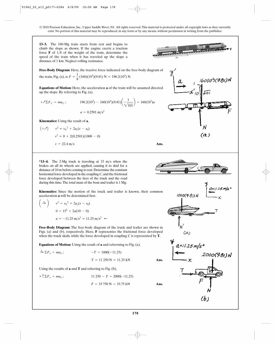
13–3. The 160-Mg train starts from rest and begins toclimb the slope as shown. If the engine exerts a tractionforce F of of the weight of the train, determine thespeed of the train when it has traveled up the slope adistance of 1 km. Neglect rolling resistance.
1>8
© 2010 Pearson Education, Inc., Upper Saddle River, NJ. All rights reserved. This material is protected under all copyright laws as they currentlyexist. No portion of this material may be reproduced, in any form or by any means, without permission in writing from the publisher.
F
101
Free-Body Diagram: Here, the tractive force indicated on the free-body diagram of
the train, Fig. (a), is .
Equations of Motion: Here, the acceleration a of the train will be assumed directedup the slope. By referring to Fig. (a),
Kinematics: Using the result of a,
Ans. v = 22.4 m>s
v2= 0 + 2(0.2501)(1000 - 0)
A +Q B v2= v0
2+ 2ac(s - s0)
a = 0.2501 m>s2
+Q©Fx¿= max¿
; 196.2(103) - 160(103)(9.81)a1
2101b = 160(103)a
F =
18
(160)(103)(9.81) N = 196.2(103) N
*13–4. The 2-Mg truck is traveling at 15 m s when thebrakes on all its wheels are applied, causing it to skid for adistance of 10 m before coming to rest.Determine the constanthorizontal force developed in the coupling C, and the frictionalforce developed between the tires of the truck and the roadduring this time.The total mass of the boat and trailer is 1 Mg.
>
Kinematics: Since the motion of the truck and trailer is known, their commonacceleration a will be determined first.
Free-Body Diagram: The free-body diagram of the truck and trailer are shown inFigs. (a) and (b), respectively. Here, F representes the frictional force developedwhen the truck skids, while the force developed in coupling C is represented by T.
Equations of Motion: Using the result of a and referrning to Fig. (a),
Ans.
Using the results of a and T and referring to Fig. (b),
Ans. F = 33 750 N = 33.75 kN
+ c ©Fx = max ; 11 250 - F = 2000(-11.25)
T = 11 250 N = 11.25 kN
:+ ©Fx = max ; -T = 1000(-11.25)
a = -11.25 m>s2= 11.25 m>s2 ;
0 = 152+ 2a(10 - 0)
a :+ b v2= v0
2+ 2ac(s - s0)
C
91962_02_s13_p0177-0284 6/8/09 10:00 AM Page 178
A
B
30�
179
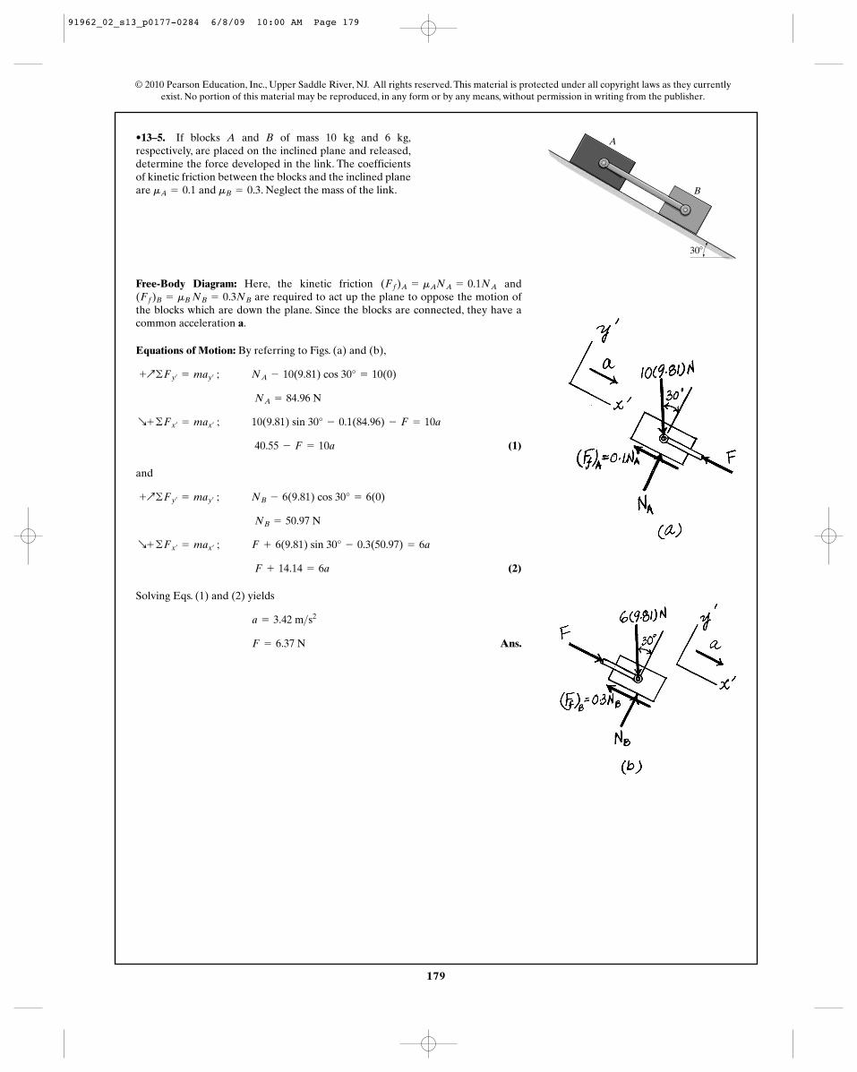
•13–5. If blocks A and B of mass 10 kg and 6 kg,respectively, are placed on the inclined plane and released,determine the force developed in the link. The coefficientsof kinetic friction between the blocks and the inclined planeare and . Neglect the mass of the link.mB = 0.3mA = 0.1
Free-Body Diagram: Here, the kinetic friction andare required to act up the plane to oppose the motion of
the blocks which are down the plane. Since the blocks are connected, they have acommon acceleration a.
Equations of Motion: By referring to Figs. (a) and (b),
(1)
and
(2)
Solving Eqs. (1) and (2) yields
Ans.F = 6.37 N
a = 3.42 m>s2
F + 14.14 = 6a
R+ ©Fx¿= max¿
; F + 6(9.81) sin 30° - 0.3(50.97) = 6a
NB = 50.97 N
+Q©Fy¿= may¿
; NB - 6(9.81) cos 30° = 6(0)
40.55 - F = 10a
R+ ©Fx¿= max¿
; 10(9.81) sin 30° - 0.1(84.96) - F = 10a
NA = 84.96 N
+Q©Fy¿= may¿
; NA - 10(9.81) cos 30° = 10(0)
(Ff)B = mB NB = 0.3NB
(Ff)A = mANA = 0.1NA
© 2010 Pearson Education, Inc., Upper Saddle River, NJ. All rights reserved. This material is protected under all copyright laws as they currentlyexist. No portion of this material may be reproduced, in any form or by any means, without permission in writing from the publisher.
A
B
30�
91962_02_s13_p0177-0284 6/8/09 10:00 AM Page 179
180
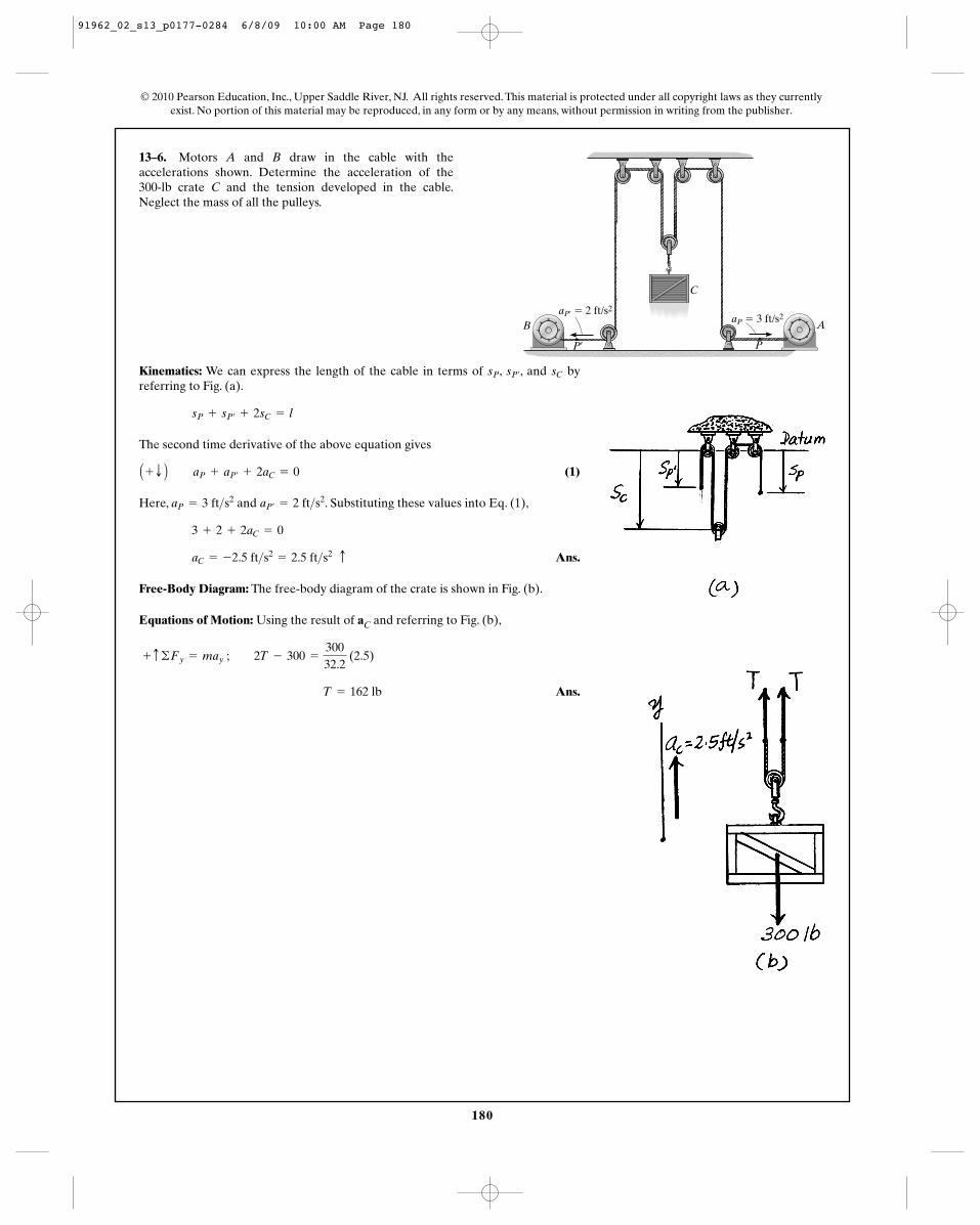
13–6. Motors A and B draw in the cable with theaccelerations shown. Determine the acceleration of the 300-lb crate C and the tension developed in the cable.Neglect the mass of all the pulleys.
© 2010 Pearson Education, Inc., Upper Saddle River, NJ. All rights reserved. This material is protected under all copyright laws as they currentlyexist. No portion of this material may be reproduced, in any form or by any means, without permission in writing from the publisher.
AB
P¿ P
C
aP¿ � 2 ft/s2aP � 3 ft/s2
Kinematics: We can express the length of the cable in terms of , , and byreferring to Fig. (a).
The second time derivative of the above equation gives
(1)
Here, and . Substituting these values into Eq. (1),
Ans.
Free-Body Diagram: The free-body diagram of the crate is shown in Fig. (b).
Equations of Motion: Using the result of aC and referring to Fig. (b),
Ans. T = 162 lb
+ c ©Fy = may ; 2T - 300 =
30032.2
(2.5)
aC = -2.5 ft>s2= 2.5 ft>s2 c
3 + 2 + 2aC = 0
aP¿= 2 ft>s2aP = 3 ft>s2
A + T B aP + aP¿+ 2aC = 0
sP + sP¿+ 2sC = l
sCsP¿sP
91962_02_s13_p0177-0284 6/8/09 10:00 AM Page 180
181
© 2010 Pearson Education, Inc., Upper Saddle River, NJ. All rights reserved. This material is protected under all copyright laws as they currentlyexist. No portion of this material may be reproduced, in any form or by any means, without permission in writing from the publisher.
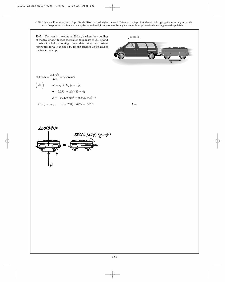
13–7. The van is traveling at 20 km h when the couplingof the trailer at A fails. If the trailer has a mass of 250 kg andcoasts 45 m before coming to rest, determine the constanthorizontal force F created by rolling friction which causesthe trailer to stop.
>
Ans.:+ ©Fx = max ; F = 250(0.3429) = 85.7 N
a = -0.3429 m>s2= 0.3429 m>s2 :
0 = 5.5562+ 2(a)(45 - 0)
a ;+ b y2= y2
0 + 2ac (s - s0)
20 km>h =
20(103)
3600= 5.556 m>s
A
20 km/h
F
91962_02_s13_p0177-0284 6/8/09 10:00 AM Page 181
182
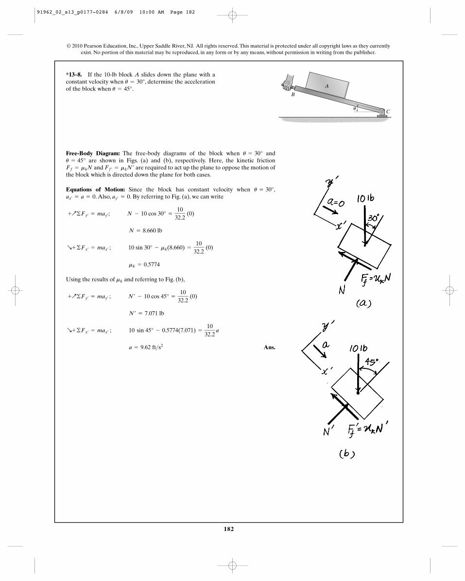
*13–8. If the 10-lb block A slides down the plane with aconstant velocity when , determine the accelerationof the block when .u = 45°
u = 30°
© 2010 Pearson Education, Inc., Upper Saddle River, NJ. All rights reserved. This material is protected under all copyright laws as they currentlyexist. No portion of this material may be reproduced, in any form or by any means, without permission in writing from the publisher.
Free-Body Diagram: The free-body diagrams of the block when andare shown in Figs. (a) and (b), respectively. Here, the kinetic friction
and are required to act up the plane to oppose the motion ofthe block which is directed down the plane for both cases.
Equations of Motion: Since the block has constant velocity when ,. Also, . By referring to Fig. (a), we can write
Using the results of and referring to Fig. (b),
Ans. a = 9.62 ft>s2
R+ ©Fx¿= max¿
; 10 sin 45° - 0.5774(7.071) =
1032.2
a
N¿ = 7.071 lb
+Q©Fy¿= may¿ ; N¿ - 10 cos 45° =
1032.2
(0)
mk
mk = 0.5774
R+ ©Fx¿= max¿ ; 10 sin 30° - mk(8.660) =
1032.2
(0)
N = 8.660 lb
+Q©Fy¿= may¿
; N - 10 cos 30° =
1032.2
(0)
ay¿= 0ax¿
= a = 0u = 30°
Ff¿= mkN¿Ff = mkN
u = 45°u = 30°
A
B
Cu
91962_02_s13_p0177-0284 6/8/09 10:00 AM Page 182
183
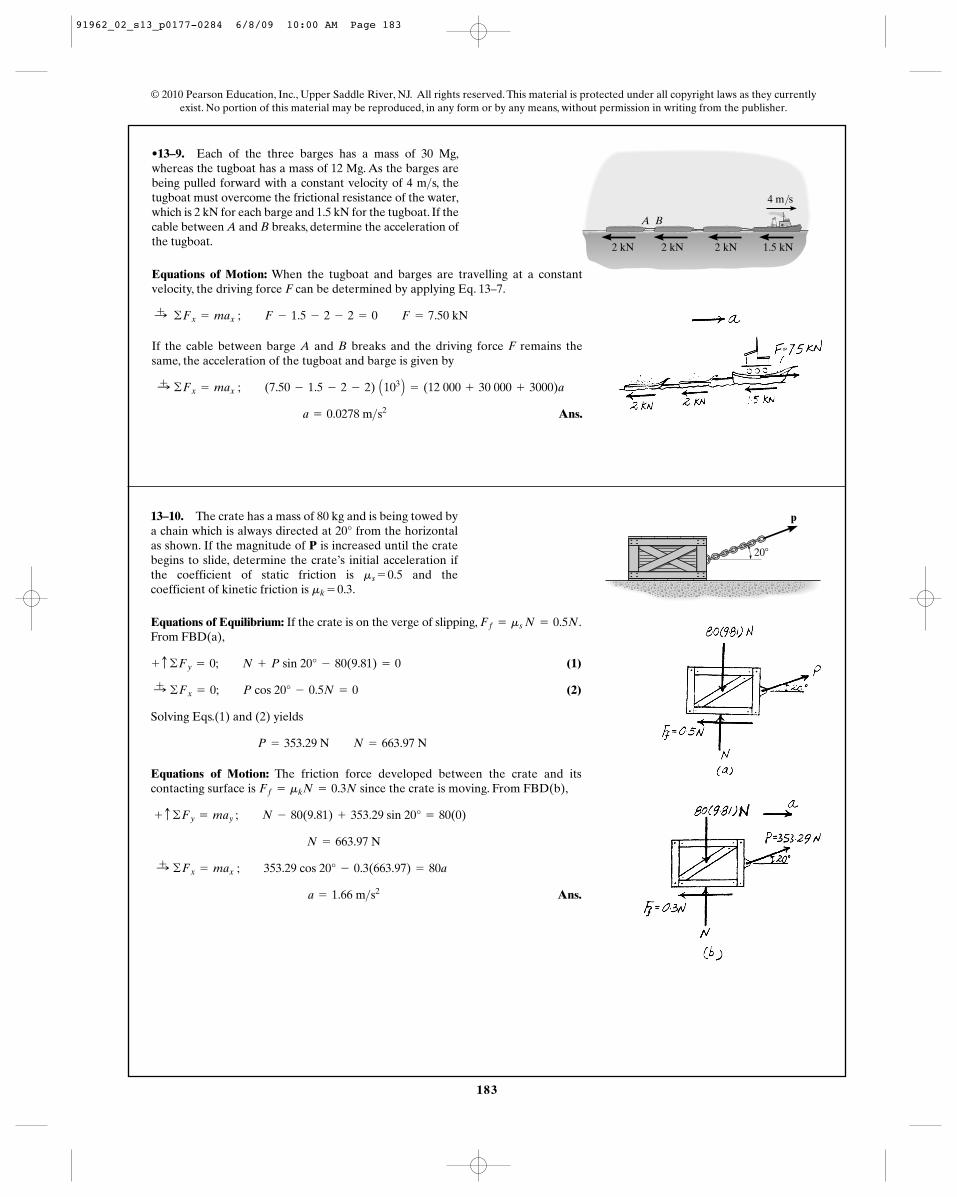
•13–9. Each of the three barges has a mass of 30 Mg,whereas the tugboat has a mass of 12 Mg. As the barges arebeing pulled forward with a constant velocity of 4 m s, thetugboat must overcome the frictional resistance of the water,which is 2 kN for each barge and 1.5 kN for the tugboat. If thecable between A and B breaks, determine the acceleration ofthe tugboat.
>
A B
1.5 kN
4 m/s
2 kN2 kN2 kN
Equations of Motion: When the tugboat and barges are travelling at a constantvelocity, the driving force F can be determined by applying Eq. 13–7.
If the cable between barge A and B breaks and the driving force F remains thesame, the acceleration of the tugboat and barge is given by
Ans. a = 0.0278 m>s2
:+ ©Fx = max ; (7.50 - 1.5 - 2 - 2) A103 B = (12 000 + 30 000 + 3000)a
:+ ©Fx = max ; F - 1.5 - 2 - 2 = 0 F = 7.50 kN
© 2010 Pearson Education, Inc., Upper Saddle River, NJ. All rights reserved. This material is protected under all copyright laws as they currentlyexist. No portion of this material may be reproduced, in any form or by any means, without permission in writing from the publisher.
13–10. The crate has a mass of 80 kg and is being towed bya chain which is always directed at 20° from the horizontalas shown. If the magnitude of P is increased until the cratebegins to slide, determine the crate’s initial acceleration ifthe coefficient of static friction is and thecoefficient of kinetic friction is .mk = 0.3
ms = 0.5
Equations of Equilibrium: If the crate is on the verge of slipping, .From FBD(a),
(1)
(2)
Solving Eqs.(1) and (2) yields
Equations of Motion: The friction force developed between the crate and itscontacting surface is since the crate is moving. From FBD(b),
Ans. a = 1.66 m>s2
:+ ©Fx = max ; 353.29 cos 20° - 0.3(663.97) = 80a
N = 663.97 N
+ c ©Fy = may ; N - 80(9.81) + 353.29 sin 20° = 80(0)
Ff = mkN = 0.3N
P = 353.29 N N = 663.97 N
:+ ©Fx = 0; P cos 20° - 0.5N = 0
+ c ©Fy = 0; N + P sin 20° - 80(9.81) = 0
Ff = ms N = 0.5N
20�
p
91962_02_s13_p0177-0284 6/8/09 10:00 AM Page 183
184
© 2010 Pearson Education, Inc., Upper Saddle River, NJ. All rights reserved. This material is protected under all copyright laws as they currentlyexist. No portion of this material may be reproduced, in any form or by any means, without permission in writing from the publisher.
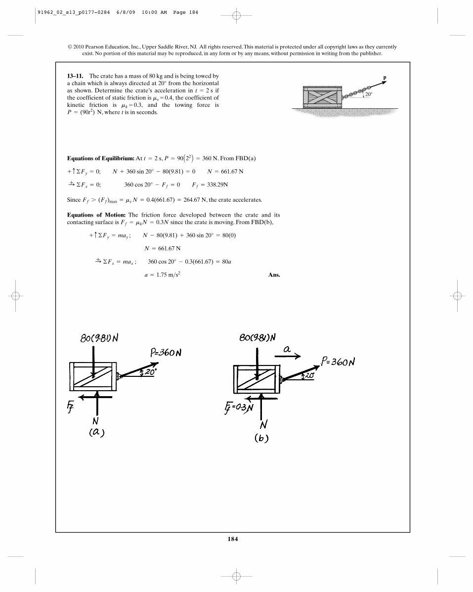
13–11. The crate has a mass of 80 kg and is being towed bya chain which is always directed at 20° from the horizontalas shown. Determine the crate’s acceleration in ifthe coefficient of static friction is the coefficient ofkinetic friction is and the towing force is
, where t is in seconds.P = (90t2) Nmk = 0.3,
ms = 0.4,t = 2 s
Equations of Equilibrium: At , . From FBD(a)
Since , the crate accelerates.
Equations of Motion: The friction force developed between the crate and itscontacting surface is since the crate is moving. From FBD(b),
Ans. a = 1.75 m>s2
:+ ©Fx = max ; 360 cos 20° - 0.3(661.67) = 80a
N = 661.67 N
+ c ©Fy = may ; N - 80(9.81) + 360 sin 20° = 80(0)
Ff = mkN = 0.3N
Ff 7 (Ff)max = ms N = 0.4(661.67) = 264.67 N
:+ ©Fx = 0; 360 cos 20° - Ff = 0 Ff = 338.29N
+ c ©Fy = 0; N + 360 sin 20° - 80(9.81) = 0 N = 661.67 N
P = 90 A22 B = 360 Nt = 2 s
20�
p
91962_02_s13_p0177-0284 6/8/09 10:00 AM Page 184
185
© 2010 Pearson Education, Inc., Upper Saddle River, NJ. All rights reserved. This material is protected under all copyright laws as they currentlyexist. No portion of this material may be reproduced, in any form or by any means, without permission in writing from the publisher.
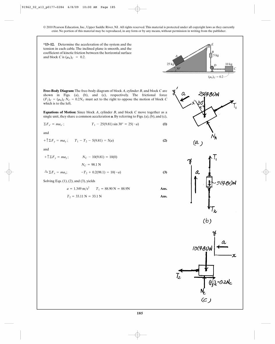
*13–12. Determine the acceleration of the system and thetension in each cable. The inclined plane is smooth, and thecoefficient of kinetic friction between the horizontal surfaceand block C is .(mk)C = 0.2
Free-Body Diagram: The free-body diagram of block A, cylinder B, and block C areshown in Figs. (a), (b), and (c), respectively. The frictional force
must act to the right to oppose the motion of block Cwhich is to the left.
Equations of Motion: Since block A, cylinder B, and block C move together as asingle unit, they share a common acceleration a. By referring to Figs. (a), (b), and (c),
(1)
and
(2)
and
(3)
Solving Eqs. (1), (2), and (3), yields
Ans.
Ans.T2 = 33.11 N = 33.1 N
a = 1.349 m>s2 T1 = 88.90 N = 88.9N
:+ ©Fx = max; -T2 + 0.2(98.1) = 10(-a)
NC = 98.1 N
+ c ©Fy = may ; NC - 10(9.81) = 10(0)
+ c ©Fy = may ; T1 - T2 - 5(9.81) = 5(a)
©Fx¿= max¿
; T1 - 25(9.81) sin 30° = 25(-a)
(Ff)C = (mk)C NC = 0.2NC
A
E
B
DC
25 kg
5 kg
10 kg30�
(mk)C � 0.2
91962_02_s13_p0177-0284 6/8/09 10:00 AM Page 185
186
© 2010 Pearson Education, Inc., Upper Saddle River, NJ. All rights reserved. This material is protected under all copyright laws as they currentlyexist. No portion of this material may be reproduced, in any form or by any means, without permission in writing from the publisher.
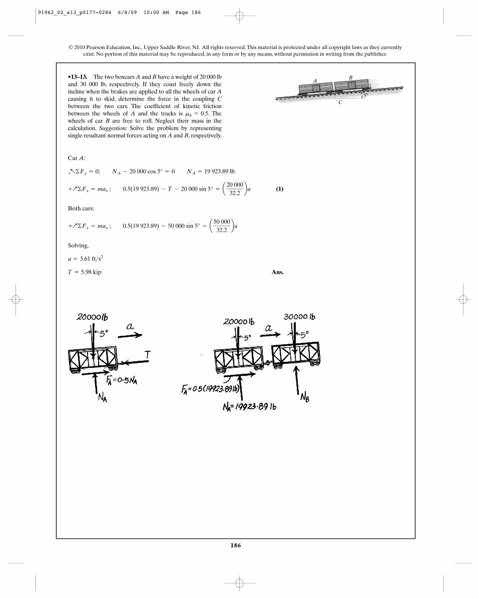
•13–13. The two boxcars A and B have a weight of 20 000 lband 30 000 lb, respectively. If they coast freely down theincline when the brakes are applied to all the wheels of car Acausing it to skid, determine the force in the coupling Cbetween the two cars. The coefficient of kinetic frictionbetween the wheels of A and the tracks is . Thewheels of car B are free to roll. Neglect their mass in thecalculation. Suggestion: Solve the problem by representingsingle resultant normal forces acting on A and B, respectively.
mk = 0.5
Car A:
(1)
Both cars:
Solving,
Ans.T = 5.98 kip
a = 3.61 ft>s2
+Q©Fx = max ; 0.5(19 923.89) - 50 000 sin 5° = a50 00032.2
ba
+Q©Fx = max ; 0.5(19 923.89) - T - 20 000 sin 5° = a20 00032.2
ba
+a©Fy = 0; NA - 20 000 cos 5° = 0 NA = 19 923.89 lb
C5�
AB
91962_02_s13_p0177-0284 6/8/09 10:00 AM Page 186
187
© 2010 Pearson Education, Inc., Upper Saddle River, NJ. All rights reserved. This material is protected under all copyright laws as they currentlyexist. No portion of this material may be reproduced, in any form or by any means, without permission in writing from the publisher.
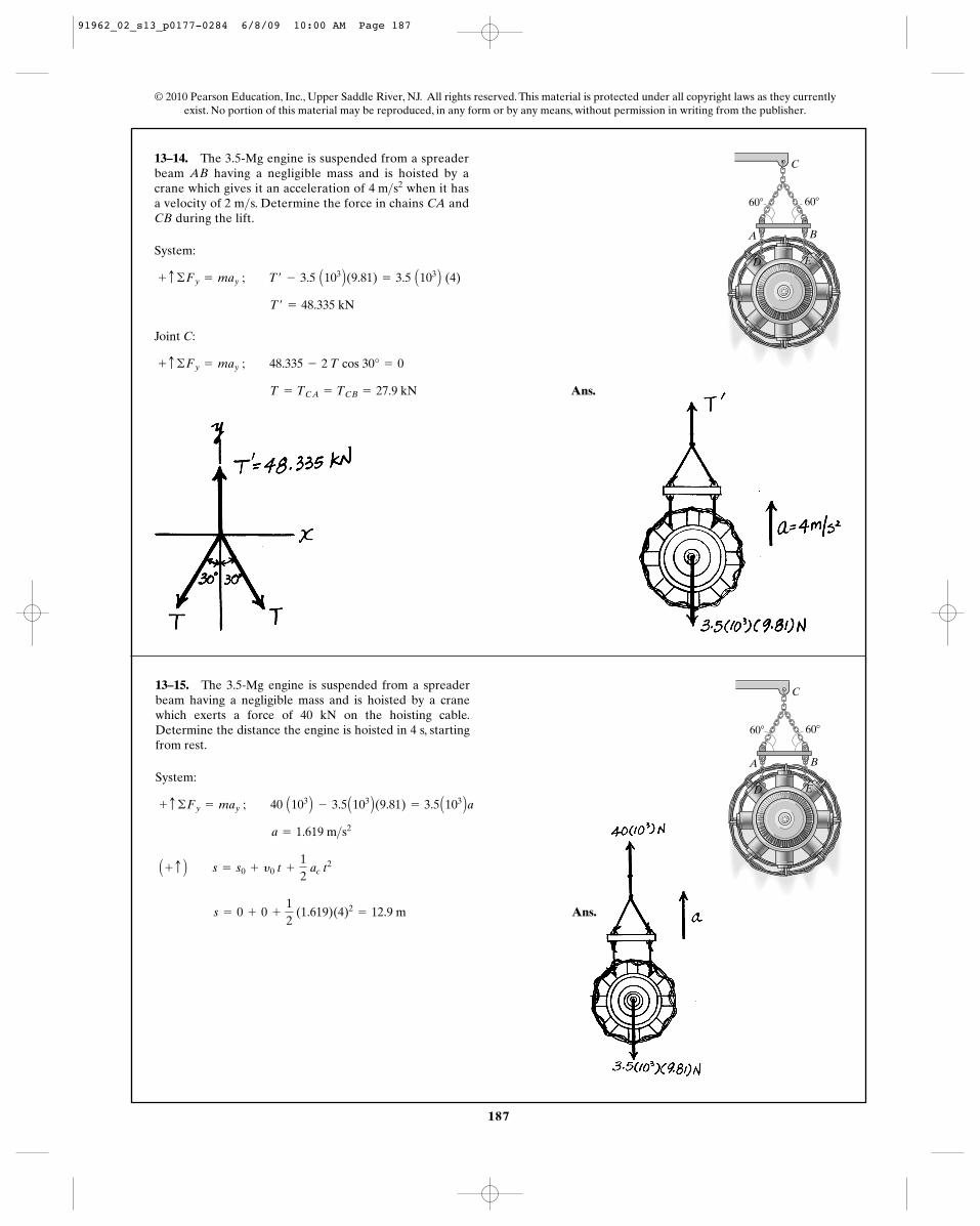
13–14. The 3.5-Mg engine is suspended from a spreaderbeam AB having a negligible mass and is hoisted by acrane which gives it an acceleration of when it hasa velocity of 2 m s. Determine the force in chains CA andCB during the lift.
>4 m>s2
System:
Joint C:
Ans. T = TCA = TCB = 27.9 kN
+ c ©Fy = may ; 48.335 - 2 T cos 30° = 0
T¿ = 48.335 kN
+ c ©Fy = may ; T¿ - 3.5 A103 B(9.81) = 3.5 A103 B (4)
60�
C
B
ED
A
60�
13–15. The 3.5-Mg engine is suspended from a spreaderbeam having a negligible mass and is hoisted by a cranewhich exerts a force of 40 kN on the hoisting cable.Determine the distance the engine is hoisted in 4 s, startingfrom rest.
System:
Ans. s = 0 + 0 +
12
(1.619)(4)2= 12.9 m
A + c B s = s0 + y0 t +
12
ac t2
a = 1.619 m>s2
+ c ©Fy = may ; 40 A103 B - 3.5 A103 B(9.81) = 3.5 A103 Ba
60�
C
B
ED
A
60�
91962_02_s13_p0177-0284 6/8/09 10:00 AM Page 187
188
© 2010 Pearson Education, Inc., Upper Saddle River, NJ. All rights reserved. This material is protected under all copyright laws as they currentlyexist. No portion of this material may be reproduced, in any form or by any means, without permission in writing from the publisher.
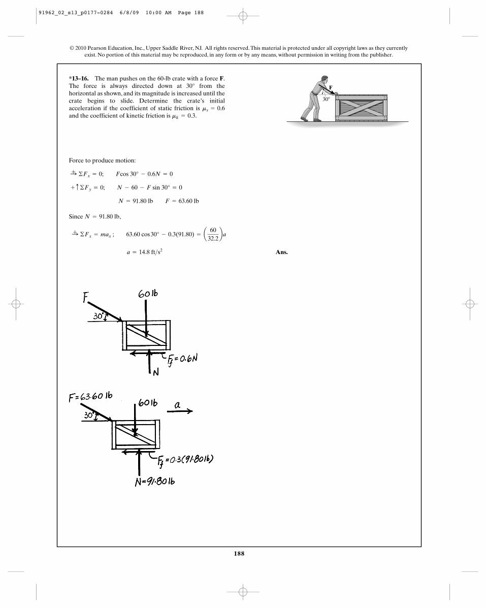
*13–16. The man pushes on the 60-lb crate with a force F.The force is always directed down at 30° from thehorizontal as shown, and its magnitude is increased until thecrate begins to slide. Determine the crate’s initialacceleration if the coefficient of static friction is and the coefficient of kinetic friction is .mk = 0.3
ms = 0.6
Force to produce motion:
Since ,
Ans. a = 14.8 ft>s2
:+ ©Fx = max ; 63.60 cos 30° - 0.3(91.80) = a60
32.2ba
N = 91.80 lb
N = 91.80 lb F = 63.60 lb
+ c ©Fy = 0; N - 60 - F sin 30° = 0
:+ ©Fx = 0; Fcos 30° - 0.6N = 0
30�
F
91962_02_s13_p0177-0284 6/8/09 10:00 AM Page 188
189
© 2010 Pearson Education, Inc., Upper Saddle River, NJ. All rights reserved. This material is protected under all copyright laws as they currentlyexist. No portion of this material may be reproduced, in any form or by any means, without permission in writing from the publisher.
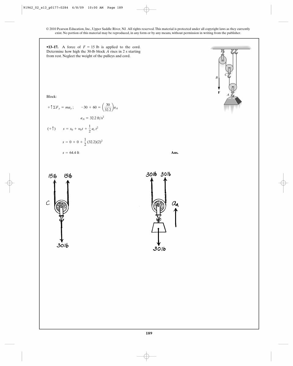
•13–17. A force of is applied to the cord.Determine how high the 30-lb block A rises in 2 s startingfrom rest. Neglect the weight of the pulleys and cord.
F = 15 lb
Block:
Ans. s = 64.4 ft
s = 0 + 0 +
12
(32.2)(2)2
(+ c) s = s0 + y0 t +
12
ac t2
aA = 32.2 ft>s2
+ c ©Fy = may ; -30 + 60 = a30
32.2baA
FA
BC
91962_02_s13_p0177-0284 6/8/09 10:00 AM Page 189
190
© 2010 Pearson Education, Inc., Upper Saddle River, NJ. All rights reserved. This material is protected under all copyright laws as they currentlyexist. No portion of this material may be reproduced, in any form or by any means, without permission in writing from the publisher.
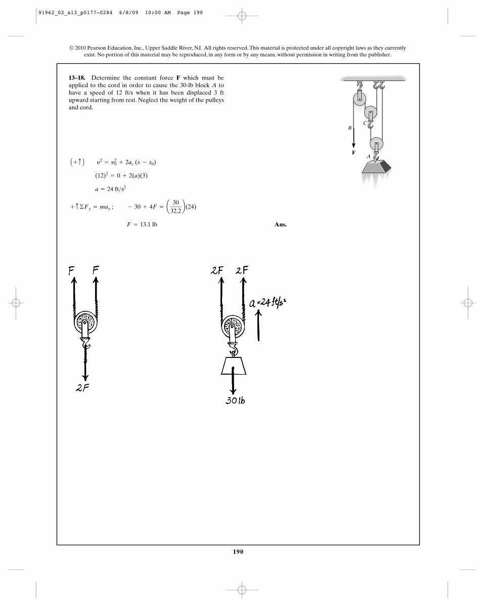
13–18. Determine the constant force F which must beapplied to the cord in order to cause the 30-lb block A tohave a speed of 12 ft/s when it has been displaced 3 ftupward starting from rest. Neglect the weight of the pulleysand cord.
Ans. F = 13.1 lb
+ c ©Fy = may ; - 30 + 4F = a30
32.2b(24)
a = 24 ft>s2
(12)2= 0 + 2(a)(3)
A + c B y2= y2
0 + 2ac (s - s0)
FA
BC
91962_02_s13_p0177-0284 6/8/09 10:00 AM Page 190
191
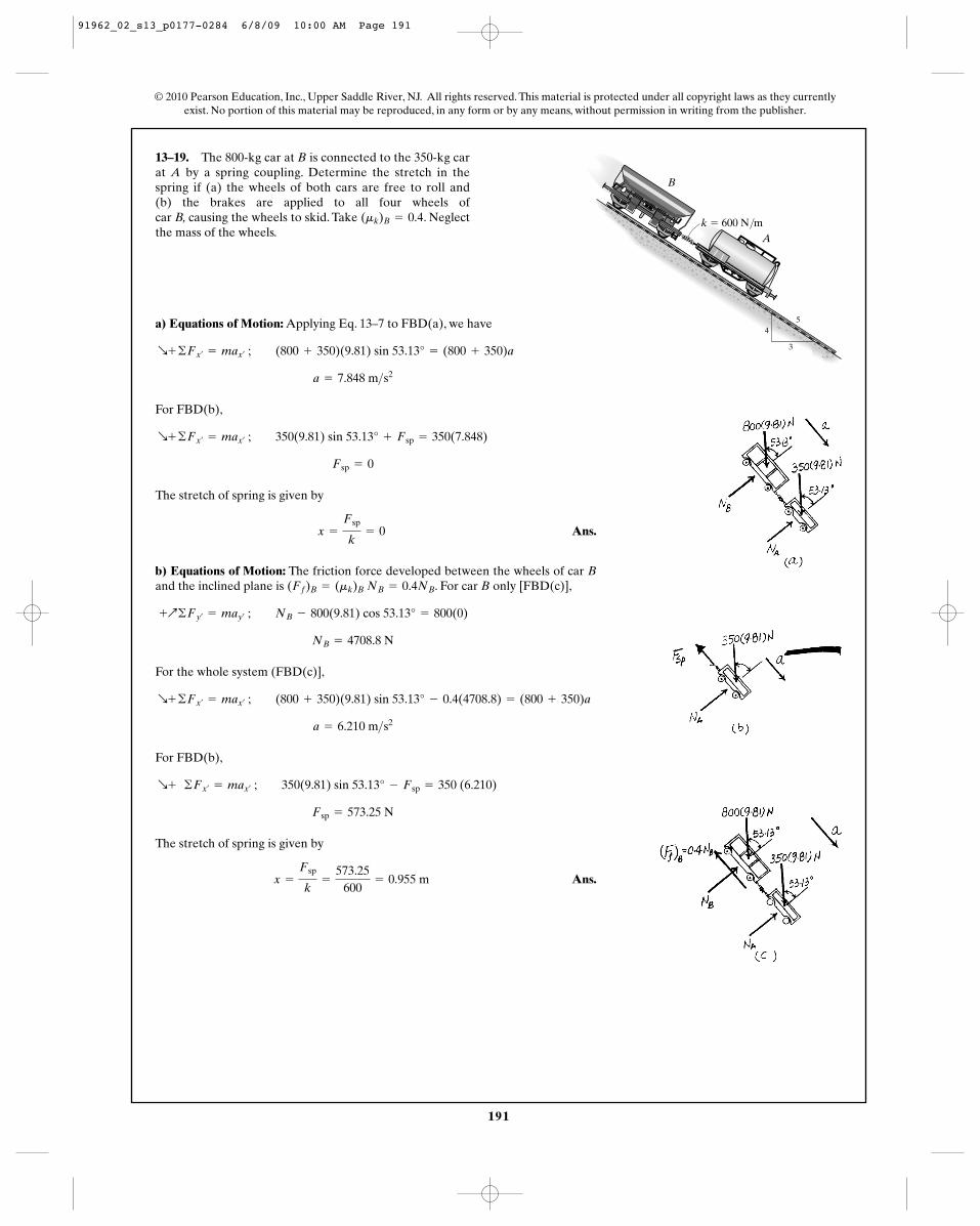
13–19. The 800-kg car at B is connected to the 350-kg carat A by a spring coupling. Determine the stretch in thespring if (a) the wheels of both cars are free to roll and (b) the brakes are applied to all four wheels of car B, causing the wheels to skid. Take . Neglectthe mass of the wheels.
(mk)B = 0.4
© 2010 Pearson Education, Inc., Upper Saddle River, NJ. All rights reserved. This material is protected under all copyright laws as they currentlyexist. No portion of this material may be reproduced, in any form or by any means, without permission in writing from the publisher.
Ak � 600 N/m
B
4
3
5a) Equations of Motion: Applying Eq. 13–7 to FBD(a), we have
For FBD(b),
The stretch of spring is given by
Ans.
b) Equations of Motion: The friction force developed between the wheels of car Band the inclined plane is . For car B only [FBD(c)],
For the whole system (FBD(c)],
For FBD(b),
The stretch of spring is given by
Ans.x =
Fsp
k=
573.25600
= 0.955 m
Fsp = 573.25 N
R+ ©Fx¿= max¿
; 350(9.81) sin 53.13° - Fsp = 350 (6.210)
a = 6.210 m>s2
R+ ©Fx¿= max¿
; (800 + 350)(9.81) sin 53.13° - 0.4(4708.8) = (800 + 350)a
NB = 4708.8 N
+Q©Fy¿= may¿
; NB - 800(9.81) cos 53.13° = 800(0)
(Ff)B = (mk)B NB = 0.4NB
x =
Fsp
k= 0
Fsp = 0
R+ ©Fx¿= max¿
; 350(9.81) sin 53.13° + Fsp = 350(7.848)
a = 7.848 m>s2
R+ ©Fx¿= max¿
; (800 + 350)(9.81) sin 53.13° = (800 + 350)a
91962_02_s13_p0177-0284 6/8/09 10:00 AM Page 191
192
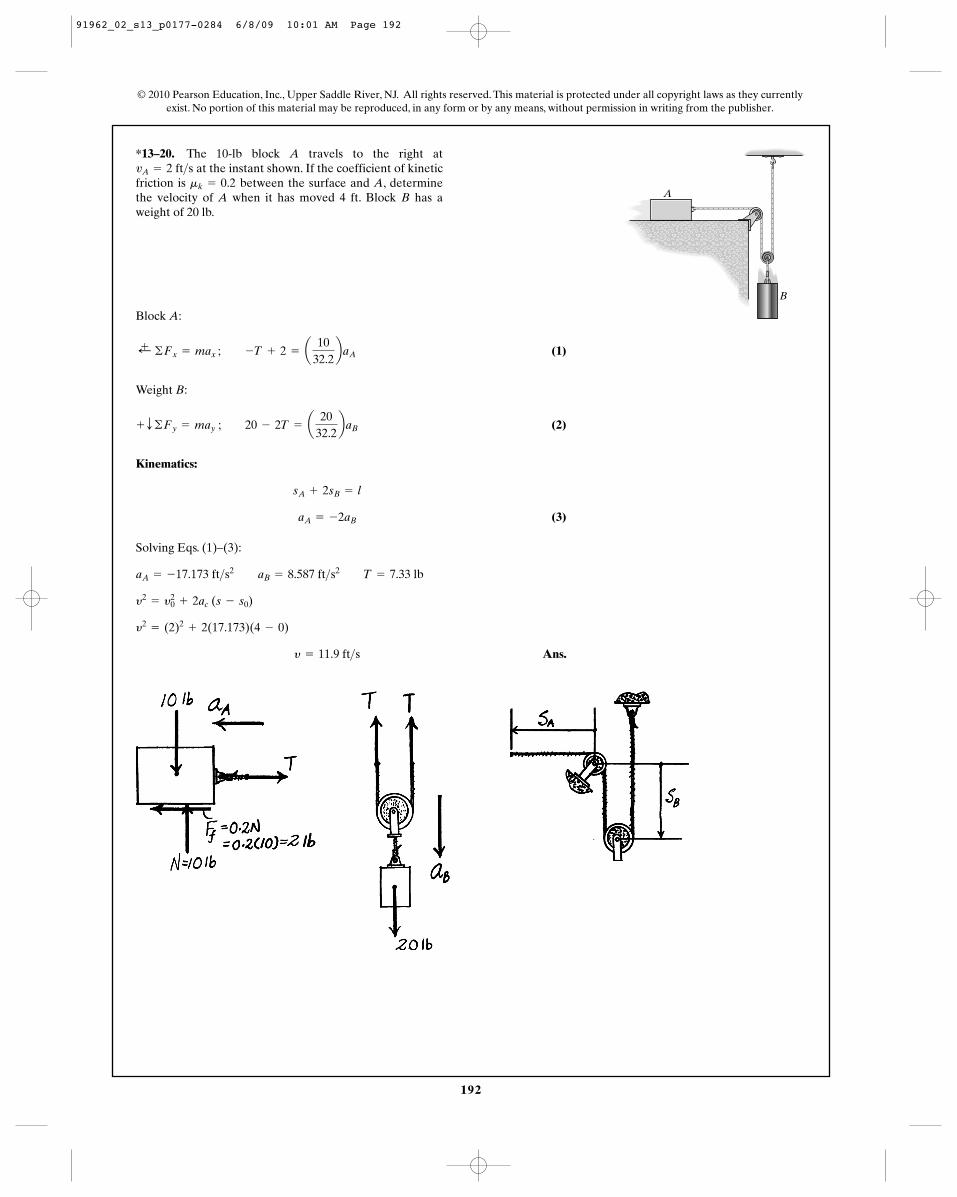
*13–20. The 10-lb block A travels to the right atat the instant shown. If the coefficient of kinetic
friction is between the surface and A, determinethe velocity of A when it has moved 4 ft. Block B has aweight of 20 lb.
mk = 0.2vA = 2 ft>s
© 2010 Pearson Education, Inc., Upper Saddle River, NJ. All rights reserved. This material is protected under all copyright laws as they currentlyexist. No portion of this material may be reproduced, in any form or by any means, without permission in writing from the publisher.
Block A:
(1)
Weight B:
(2)
Kinematics:
(3)
Solving Eqs. (1)–(3):
Ans.y = 11.9 ft>s
y2= (2)2
+ 2(17.173)(4 - 0)
y2= y2
0 + 2ac (s - s0)
aA = -17.173 ft>s2 aB = 8.587 ft>s2 T = 7.33 lb
aA = -2aB
sA + 2sB = l
+ T ©Fy = may ; 20 - 2T = a20
32.2baB
;+ ©Fx = max ; -T + 2 = a10
32.2baA
A
B
91962_02_s13_p0177-0284 6/8/09 10:01 AM Page 192
193
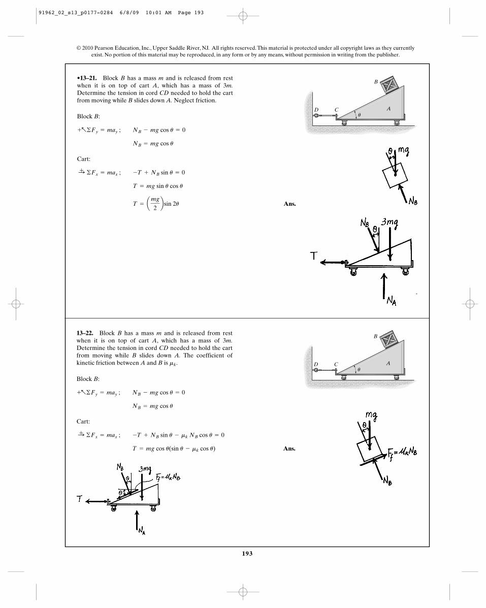
•13–21. Block B has a mass m and is released from restwhen it is on top of cart A, which has a mass of 3m.Determine the tension in cord CD needed to hold the cartfrom moving while B slides down A. Neglect friction.
Block B:
Cart:
Ans. T = amg
2bsin 2u
T = mg sin u cos u
:+ ©Fx = max ; -T + NB sin u = 0
NB = mg cos u
+a©Fy = may ; NB - mg cos u = 0
© 2010 Pearson Education, Inc., Upper Saddle River, NJ. All rights reserved. This material is protected under all copyright laws as they currentlyexist. No portion of this material may be reproduced, in any form or by any means, without permission in writing from the publisher.
Au
B
CD
13–22. Block B has a mass m and is released from restwhen it is on top of cart A, which has a mass of 3m.Determine the tension in cord CD needed to hold the cartfrom moving while B slides down A. The coefficient ofkinetic friction between A and B is .mk
Block B:
Cart:
Ans. T = mg cos u(sin u - mk cos u)
:+ ©Fx = max ; -T + NB sin u - mk NB cos u = 0
NB = mg cos u
+a©Fy = may ; NB - mg cos u = 0
Au
B
CD
91962_02_s13_p0177-0284 6/8/09 10:01 AM Page 193
194
© 2010 Pearson Education, Inc., Upper Saddle River, NJ. All rights reserved. This material is protected under all copyright laws as they currentlyexist. No portion of this material may be reproduced, in any form or by any means, without permission in writing from the publisher.
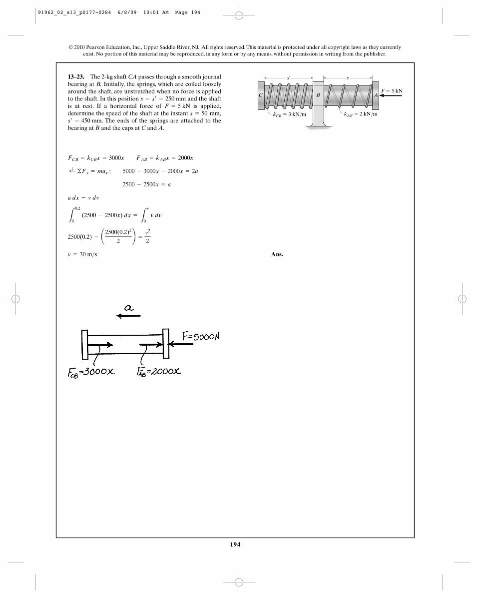
13–23. The 2-kg shaft CA passes through a smooth journalbearing at B. Initially, the springs, which are coiled looselyaround the shaft, are unstretched when no force is appliedto the shaft. In this position and the shaftis at rest. If a horizontal force of is applied,determine the speed of the shaft at the instant ,
. The ends of the springs are attached to thebearing at B and the caps at C and A.s¿ = 450 mm
s = 50 mmF = 5 kN
s = s¿ = 250 mm
Ans.v = 30 m>s
2500(0.2) - ¢2500(0.2)2
2≤ =
v2
2
L
0.2
0 (2500 - 2500x) dx =
L
v
0 v dv
a dx - v dv
2500 - 2500x = a
;+ ©Fx = max ; 5000 - 3000x - 2000x = 2a
FCB = kCBx = 3000x FAB = kABx = 2000x
s¿ s
A
kCB � 3 kN/m kAB � 2 kN/m
F � 5 kNC B
91962_02_s13_p0177-0284 6/8/09 10:01 AM Page 194
195
© 2010 Pearson Education, Inc., Upper Saddle River, NJ. All rights reserved. This material is protected under all copyright laws as they currentlyexist. No portion of this material may be reproduced, in any form or by any means, without permission in writing from the publisher.
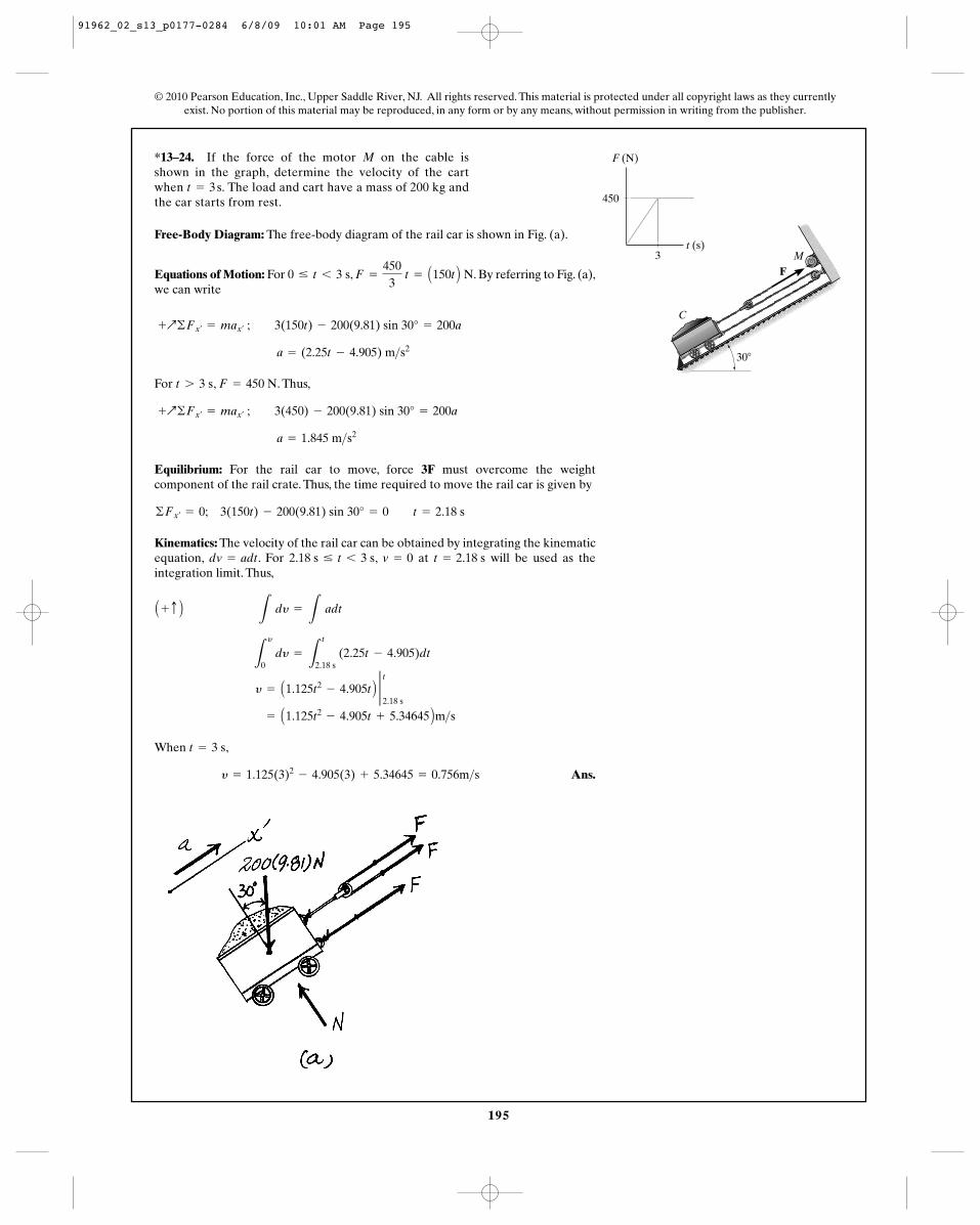
*13–24. If the force of the motor M on the cable isshown in the graph, determine the velocity of the cartwhen The load and cart have a mass of 200 kg andthe car starts from rest.
t = 3 s.
Free-Body Diagram: The free-body diagram of the rail car is shown in Fig. (a).
Equations of Motion: For , . By referring to Fig. (a),we can write
For , . Thus,
Equilibrium: For the rail car to move, force 3F must overcome the weightcomponent of the rail crate. Thus, the time required to move the rail car is given by
Kinematics: The velocity of the rail car can be obtained by integrating the kinematicequation, . For , at will be used as theintegration limit. Thus,
When ,
Ans.y = 1.125(3)2- 4.905(3) + 5.34645 = 0.756m>s
t = 3 s
= A1.125t2- 4.905t + 5.34645 Bm>s
y = A1.125t2- 4.905t B 2 t
2.18 s
L
y
0 dy =
L
t
2.18 s (2.25t - 4.905)dt
A + c B L
dy =
L adt
t = 2.18 sv = 02.18 s … t 6 3 sdv = adt
©Fx¿= 0; 3(150t) - 200(9.81) sin 30° = 0 t = 2.18 s
a = 1.845 m>s2
+Q©Fx¿= max¿
; 3(450) - 200(9.81) sin 30° = 200a
F = 450 Nt 7 3 s
a = (2.25t - 4.905) m>s2
+Q©Fx¿= max¿
; 3(150t) - 200(9.81) sin 30° = 200a
F =
4503
t = A150t B N0 … t 6 3 s
C
MF
F (N)
450
3t (s)
30�
91962_02_s13_p0177-0284 6/8/09 10:01 AM Page 195
196
© 2010 Pearson Education, Inc., Upper Saddle River, NJ. All rights reserved. This material is protected under all copyright laws as they currentlyexist. No portion of this material may be reproduced, in any form or by any means, without permission in writing from the publisher.
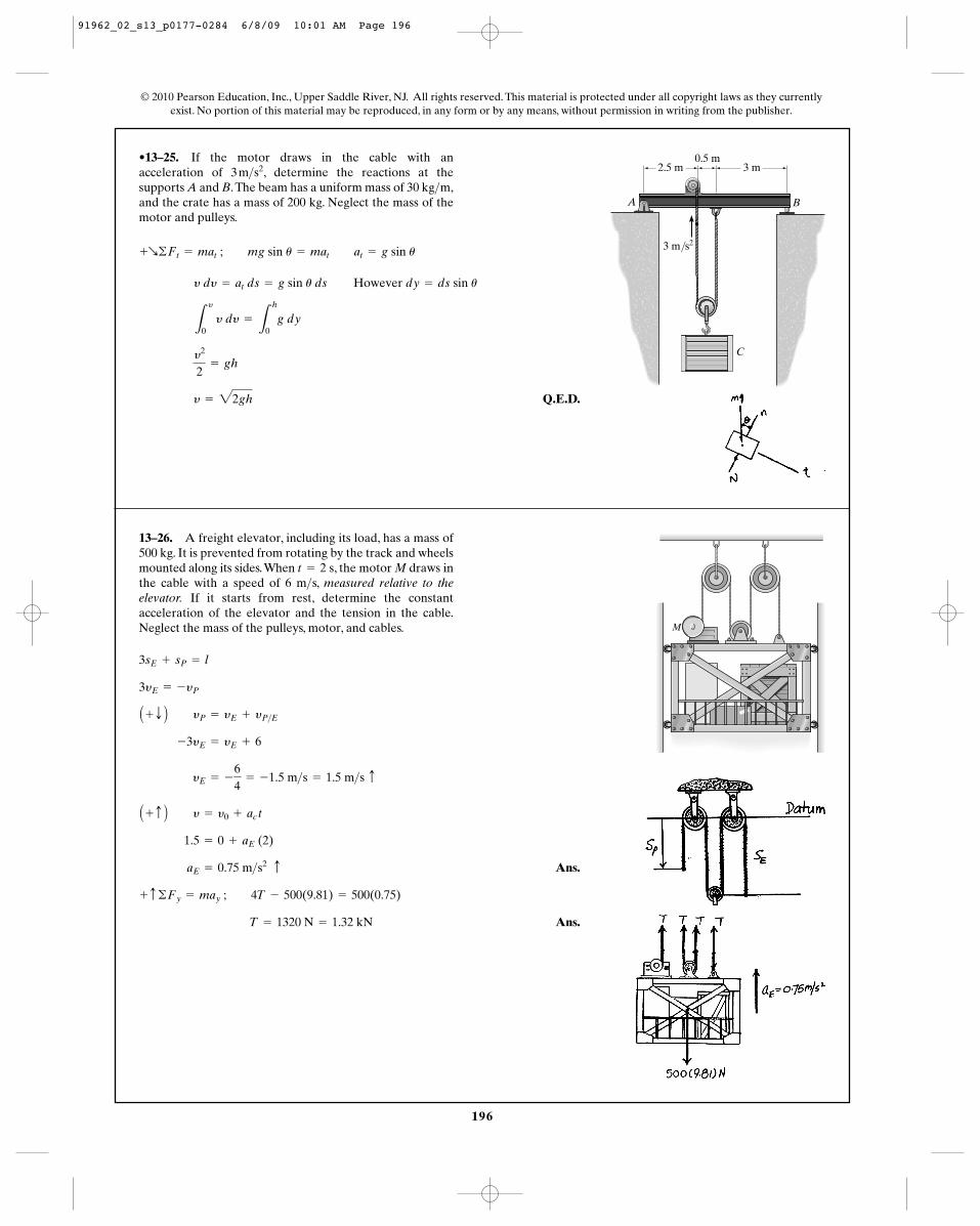
•13–25. If the motor draws in the cable with anacceleration of , determine the reactions at thesupports A and B.The beam has a uniform mass of 30 kg m,and the crate has a mass of 200 kg. Neglect the mass of themotor and pulleys.
>3 m>s2
However
Q.E.D. y = 22gh
y2
2= gh
L
y
0 y dy =
L
h
0g dy
dy = ds sin uy dy = at ds = g sin u ds
+R©Ft = mat ; mg sin u = mat at = g sin u
C
A B
2.5 m 3 m0.5 m
3 m/s2
13–26. A freight elevator, including its load, has a mass of500 kg. It is prevented from rotating by the track and wheelsmounted along its sides.When , the motor M draws inthe cable with a speed of 6 m s, measured relative to theelevator. If it starts from rest, determine the constantacceleration of the elevator and the tension in the cable.Neglect the mass of the pulleys, motor, and cables.
>t = 2 s
Ans.
Ans. T = 1320 N = 1.32 kN
+ c ©Fy = may ; 4T - 500(9.81) = 500(0.75)
aE = 0.75 m>s2 c
1.5 = 0 + aE (2)
A + c B y = y0 + ac t
yE = -
64
= -1.5 m>s = 1.5 m>s c
-3yE = yE + 6
A + T B yP = yE + yP>E
3yE = -yP
3sE + sP = l
M
91962_02_s13_p0177-0284 6/8/09 10:01 AM Page 196
60�
A
B
D
C
E
197
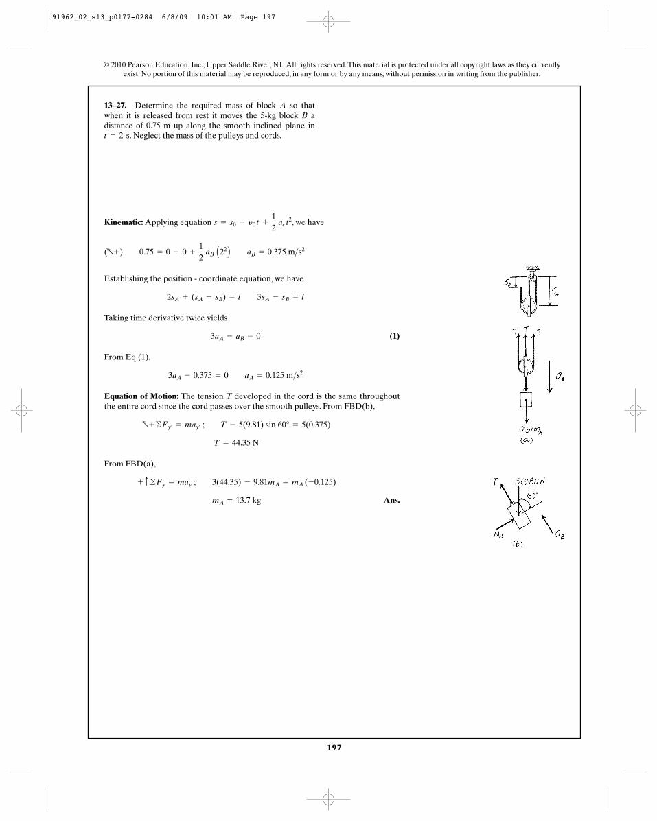
13–27. Determine the required mass of block A so thatwhen it is released from rest it moves the 5-kg block B adistance of 0.75 m up along the smooth inclined plane in
. Neglect the mass of the pulleys and cords.t = 2 s
Kinematic: Applying equation , we have
Establishing the position - coordinate equation, we have
Taking time derivative twice yields
(1)
From Eq.(1),
Equation of Motion: The tension T developed in the cord is the same throughoutthe entire cord since the cord passes over the smooth pulleys. From FBD(b),
From FBD(a),
Ans. mA = 13.7 kg
+ c ©Fy = may ; 3(44.35) - 9.81mA = mA (-0.125)
T = 44.35 N
a+ ©Fy¿= may¿
; T - 5(9.81) sin 60° = 5(0.375)
3aA - 0.375 = 0 aA = 0.125 m>s2
3aA - aB = 0
2sA + (sA - sB) = l 3sA - sB = l
(a+) 0.75 = 0 + 0 +
12
aB A22 B aB = 0.375 m>s2
s = s0 + y0 t +
12
ac t2
© 2010 Pearson Education, Inc., Upper Saddle River, NJ. All rights reserved. This material is protected under all copyright laws as they currentlyexist. No portion of this material may be reproduced, in any form or by any means, without permission in writing from the publisher.
91962_02_s13_p0177-0284 6/8/09 10:01 AM Page 197
198
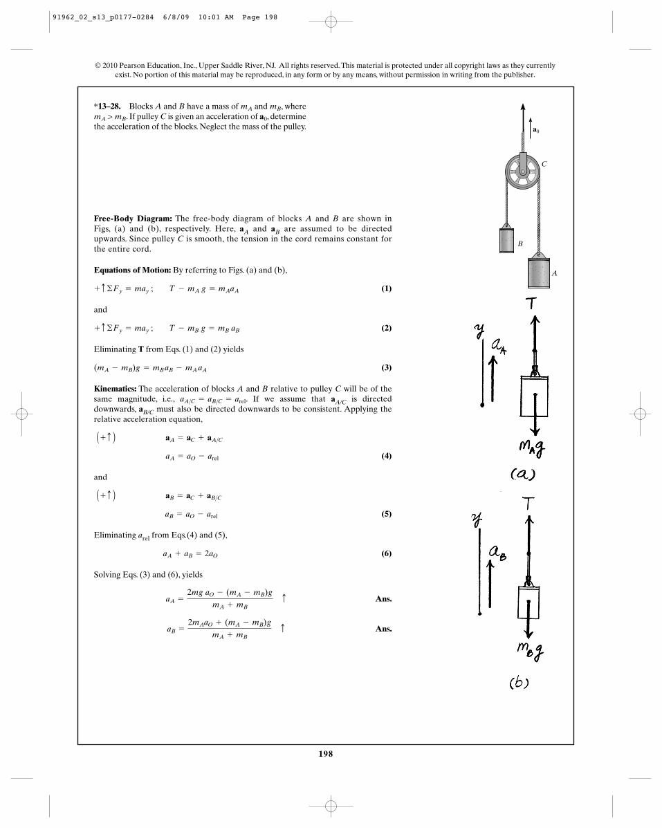
*13–28. Blocks A and B have a mass of and , where. If pulley C is given an acceleration of , determine
the acceleration of the blocks. Neglect the mass of the pulley.a0mA > mB
mBmA
© 2010 Pearson Education, Inc., Upper Saddle River, NJ. All rights reserved. This material is protected under all copyright laws as they currentlyexist. No portion of this material may be reproduced, in any form or by any means, without permission in writing from the publisher.
Free-Body Diagram: The free-body diagram of blocks A and B are shown inFigs, (a) and (b), respectively. Here, aA and aB are assumed to be directedupwards. Since pulley C is smooth, the tension in the cord remains constant forthe entire cord.
Equations of Motion: By referring to Figs. (a) and (b),
(1)
and
(2)
Eliminating T from Eqs. (1) and (2) yields
(3)
Kinematics: The acceleration of blocks A and B relative to pulley C will be of thesame magnitude, i.e., . If we assume that aA/C is directeddownwards, aB/C must also be directed downwards to be consistent. Applying therelative acceleration equation,
(4)
and
(5)
Eliminating arel from Eqs.(4) and (5),
(6)
Solving Eqs. (3) and (6), yields
Ans.
Ans.aB =
2mAaO + (mA - mB)g
mA + mB c
aA =
2mg aO - (mA - mB)g
mA + mB c
aA + aB = 2aO
aB = aO - arel
A + c B aB = aC + aB>C
aA = aO - arel
A + c B aA = aC + aA>C
aA>C = aB>C = arel
(mA - mB)g = mB aB - mA aA
+ c ©Fy = may ; T - mB g = mB aB
+ c ©Fy = may ; T - mA g = mAaA
a0
C
A
B
91962_02_s13_p0177-0284 6/8/09 10:01 AM Page 198
199
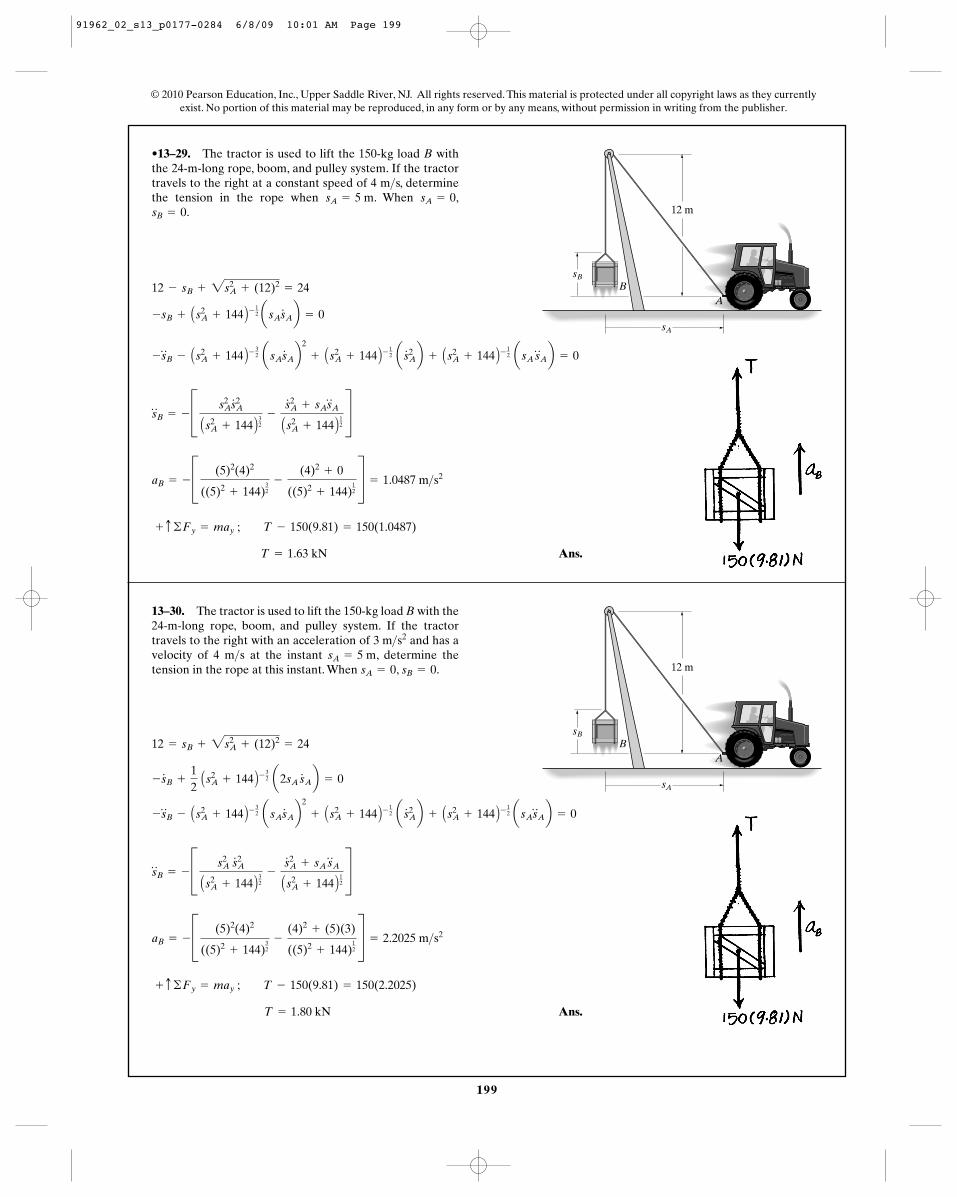
•13–29. The tractor is used to lift the 150-kg load B withthe 24-m-long rope, boom, and pulley system. If the tractortravels to the right at a constant speed of 4 m s, determinethe tension in the rope when . When ,
.sB = 0sA = 0sA = 5 m
>
sA
sB
AB
12 m
13–30. The tractor is used to lift the 150-kg load B with the24-m-long rope, boom, and pulley system. If the tractortravels to the right with an acceleration of and has avelocity of 4 m s at the instant , determine thetension in the rope at this instant. When , .sB = 0sA = 0
sA = 5 m>3 m>s2
Ans. T = 1.80 kN
+ c ©Fy = may ; T - 150(9.81) = 150(2.2025)
aB = - C (5)2(4)2
((5)2+ 144)
32
-
(4)2+ (5)(3)
((5)2+ 144)
12
S = 2.2025 m>s2
s$
B = - C s2A s
# 2A
As2A + 144 B
32
-
s# 2A + sA s
$
A
As2A + 144 B
12
S
-s$
B - As2A + 144 B-
32 asAs
#
Ab2
+ As2A + 144 B-
12 as
# 2Ab + As2
A + 144 B- 12 asAs
$
Ab = 0
-s#
B +
12
As2A + 144 B-
32 a2sA s
#
Ab = 0
12 = sB + 2s2A + (12)2
= 24
sA
sB
AB
12 m
Ans. T = 1.63 kN
+ c ©Fy = may ; T - 150(9.81) = 150(1.0487)
aB = - C (5)2(4)2
((5)2+ 144)
32
-
(4)2+ 0
((5)2+ 144)
12
S = 1.0487 m>s2
s$
B = - C s2As
# 2A
As2A + 144 B
32
-
s# 2A + sAs
$
A
As2A + 144 B
12
S
-s$
B - As2A + 144 B-
32 asAs
#
Ab2
+ As2A + 144 B-
12 as
# 2Ab + As2
A + 144 B- 12 asA s
$
Ab = 0
-sB + As2A + 144 B-
12 asAs
#
Ab = 0
12 - sB + 2s2A + (12)2
= 24
© 2010 Pearson Education, Inc., Upper Saddle River, NJ. All rights reserved. This material is protected under all copyright laws as they currentlyexist. No portion of this material may be reproduced, in any form or by any means, without permission in writing from the publisher.
91962_02_s13_p0177-0284 6/8/09 10:01 AM Page 199
200
© 2010 Pearson Education, Inc., Upper Saddle River, NJ. All rights reserved. This material is protected under all copyright laws as they currentlyexist. No portion of this material may be reproduced, in any form or by any means, without permission in writing from the publisher.
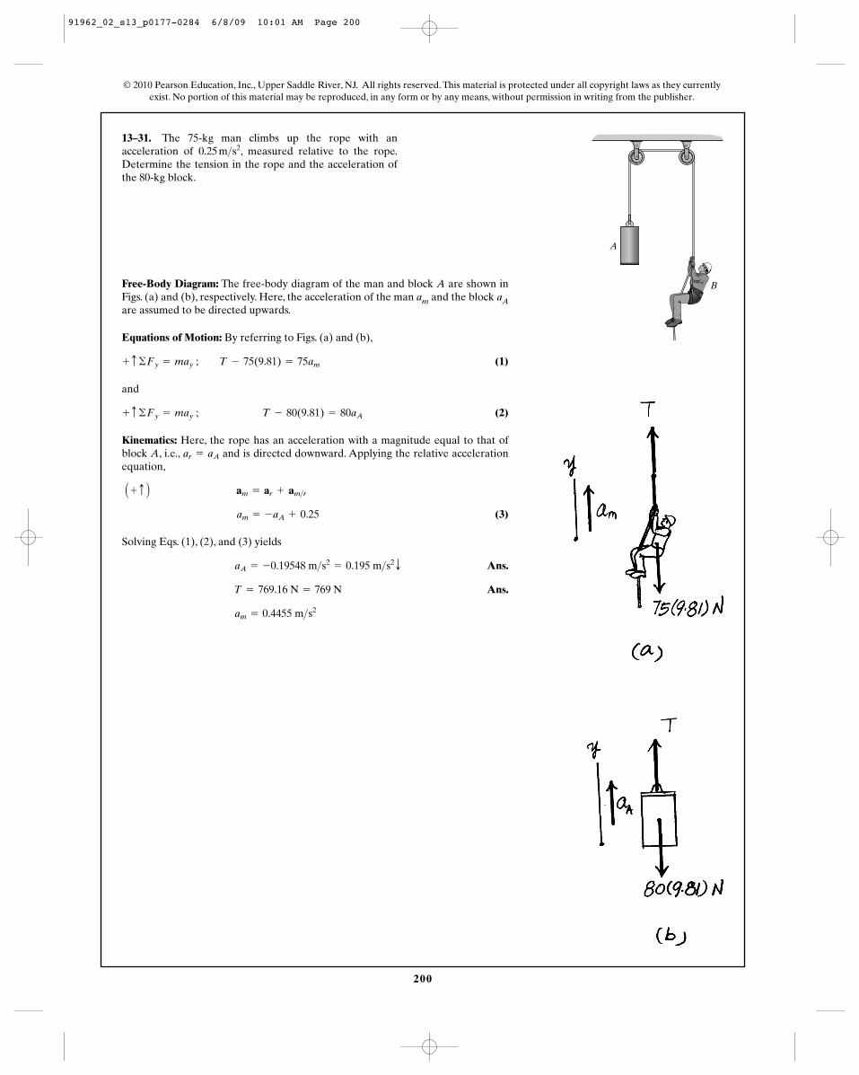
13–31. The 75-kg man climbs up the rope with anacceleration of , measured relative to the rope.Determine the tension in the rope and the acceleration ofthe 80-kg block.
0.25 m>s2
Free-Body Diagram: The free-body diagram of the man and block A are shown inFigs. (a) and (b), respectively. Here, the acceleration of the man am and the block aAare assumed to be directed upwards.
Equations of Motion: By referring to Figs. (a) and (b),
(1)
and
(2)
Kinematics: Here, the rope has an acceleration with a magnitude equal to that ofblock A, i.e., and is directed downward. Applying the relative accelerationequation,
(3)
Solving Eqs. (1), (2), and (3) yields
Ans.
Ans.
am = 0.4455 m>s2
T = 769.16 N = 769 N
aA = -0.19548 m>s2= 0.195 m>s2
T
am = -aA + 0.25
A + c B am = ar + am>r
ar = aA
+ c ©Fy = may ; T - 80(9.81) = 80aA
+ c ©Fy = may ; T - 75(9.81) = 75am
A
B
91962_02_s13_p0177-0284 6/8/09 10:01 AM Page 200
201
© 2010 Pearson Education, Inc., Upper Saddle River, NJ. All rights reserved. This material is protected under all copyright laws as they currentlyexist. No portion of this material may be reproduced, in any form or by any means, without permission in writing from the publisher.
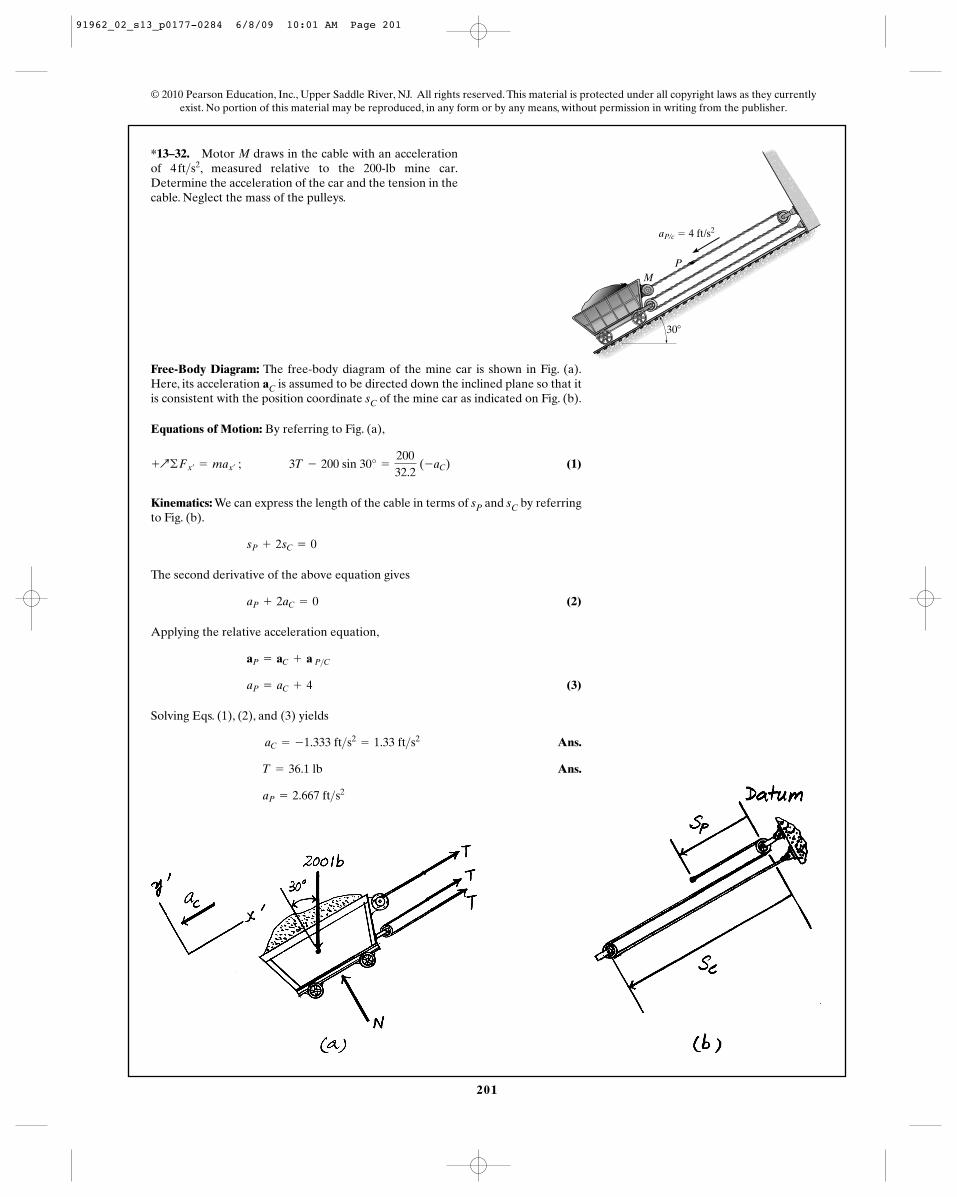
*13–32. Motor M draws in the cable with an accelerationof , measured relative to the 200-lb mine car.Determine the acceleration of the car and the tension in thecable. Neglect the mass of the pulleys.
4 ft>s2
PM
aP/c � 4 ft/s2
30�
Free-Body Diagram: The free-body diagram of the mine car is shown in Fig. (a).Here, its acceleration aC is assumed to be directed down the inclined plane so that itis consistent with the position coordinate sC of the mine car as indicated on Fig. (b).
Equations of Motion: By referring to Fig. (a),
(1)
Kinematics: We can express the length of the cable in terms of sP and sC by referringto Fig. (b).
The second derivative of the above equation gives
(2)
Applying the relative acceleration equation,
(3)
Solving Eqs. (1), (2), and (3) yields
Ans.
Ans.
aP = 2.667 ft>s2
T = 36.1 lb
aC = -1.333 ft>s2= 1.33 ft>s2
aP = aC + 4
aP = aC + a P>C
aP + 2aC = 0
sP + 2sC = 0
+Q©Fx¿= max¿
; 3T - 200 sin 30° =
20032.2
(-aC)
91962_02_s13_p0177-0284 6/8/09 10:01 AM Page 201
202
© 2010 Pearson Education, Inc., Upper Saddle River, NJ. All rights reserved. This material is protected under all copyright laws as they currentlyexist. No portion of this material may be reproduced, in any form or by any means, without permission in writing from the publisher.
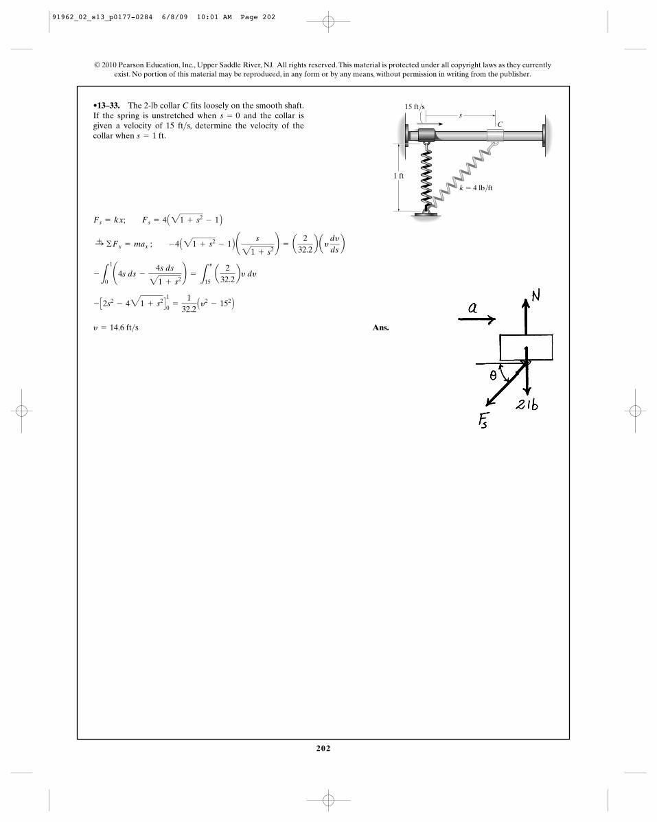
•13–33. The 2-lb collar C fits loosely on the smooth shaft.If the spring is unstretched when and the collar isgiven a velocity of 15 ft s, determine the velocity of thecollar when .s = 1 ft
>s = 0
Ans.y = 14.6 ft>s
- C2s2- 431 + s2 D
1
0=
132.2Ay2
- 152 B
-
L
1
0¢4s ds -
4s ds
21 + s2≤ =
L
y
15 a
232.2by dy
:+ ©Fx = max ; -4 A21 + s2- 1 B ¢ s
21 + s2≤ = a
232.2b ay
dy
dsb
Fs = kx; Fs = 4 A21 + s2- 1 B
C
1 ft
k � 4 lb/ft
15 ft/ss
91962_02_s13_p0177-0284 6/8/09 10:01 AM Page 202
203
© 2010 Pearson Education, Inc., Upper Saddle River, NJ. All rights reserved. This material is protected under all copyright laws as they currentlyexist. No portion of this material may be reproduced, in any form or by any means, without permission in writing from the publisher.
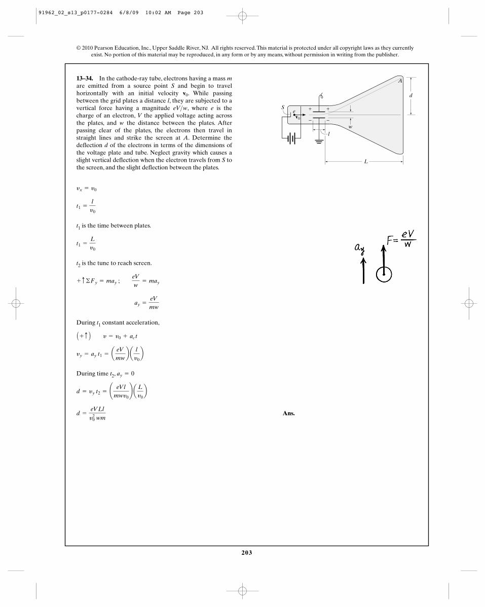
13–34. In the cathode-ray tube, electrons having a mass mare emitted from a source point S and begin to travelhorizontally with an initial velocity . While passingbetween the grid plates a distance l, they are subjected to avertical force having a magnitude eV w, where e is thecharge of an electron, V the applied voltage acting acrossthe plates, and w the distance between the plates. Afterpassing clear of the plates, the electrons then travel instraight lines and strike the screen at A. Determine thedeflection d of the electrons in terms of the dimensions ofthe voltage plate and tube. Neglect gravity which causes aslight vertical deflection when the electron travels from S tothe screen, and the slight deflection between the plates.
>
v0
t1 is the time between plates.
t2 is the tune to reach screen.
During t1 constant acceleration,
During time t2,
Ans.d =
eVLl
y20 wm
d = yy t2 = ¢ eVl
mwy0≤ a Ly0b
ay = 0
yy = ay t1 = aeV
mwb a
ly0b
A + c B y = y0 + ac t
ay =
eV
mw
+ c ©Fy = may ; eV
w= may
t1 =
Ly0
t1 =
ly0
yx = y0
L
l
d
Sev0
w
A
+ +
– –
91962_02_s13_p0177-0284 6/8/09 10:02 AM Page 203
204
© 2010 Pearson Education, Inc., Upper Saddle River, NJ. All rights reserved. This material is protected under all copyright laws as they currentlyexist. No portion of this material may be reproduced, in any form or by any means, without permission in writing from the publisher.
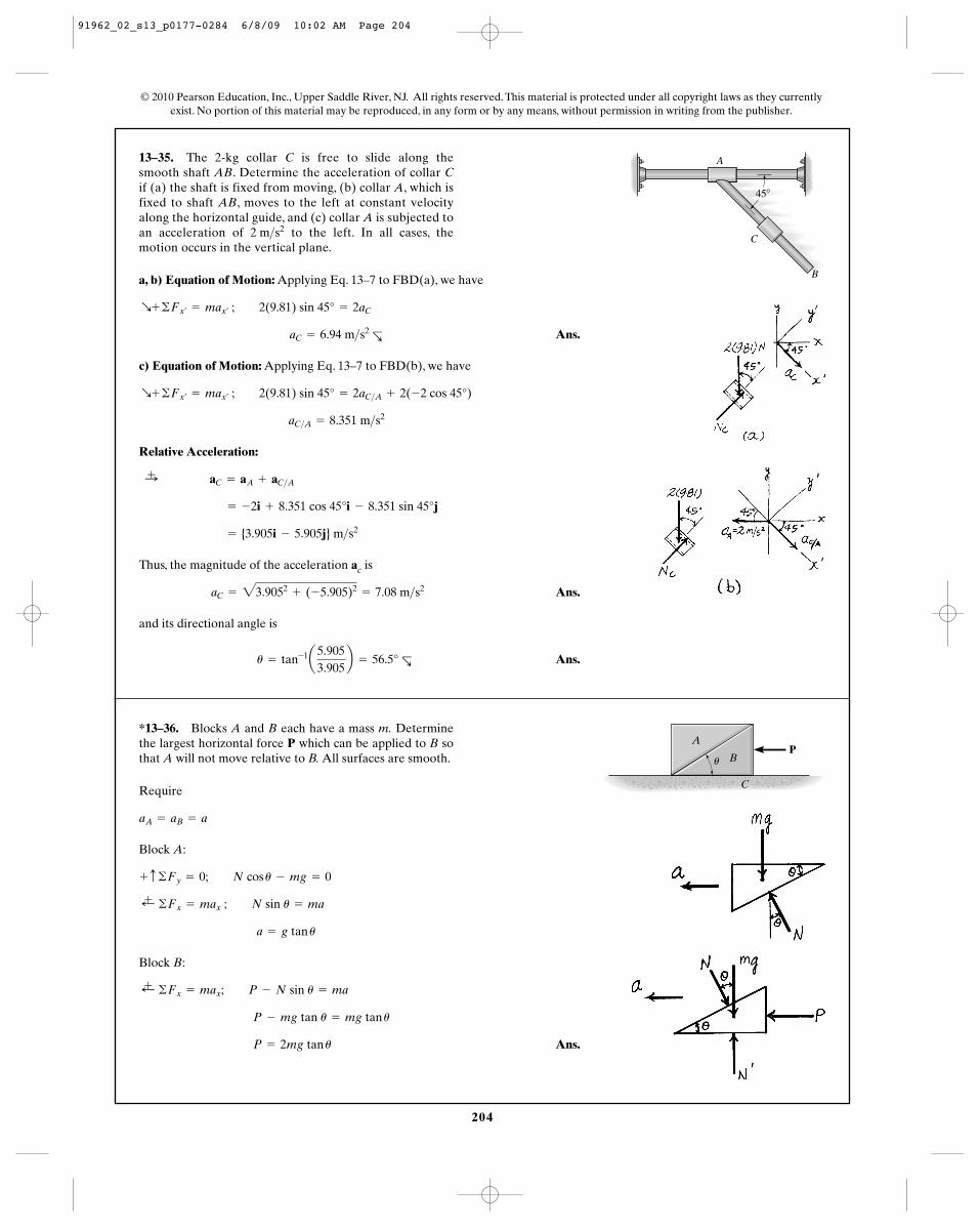
13–35. The 2-kg collar C is free to slide along thesmooth shaft AB. Determine the acceleration of collar Cif (a) the shaft is fixed from moving, (b) collar A, which isfixed to shaft AB, moves to the left at constant velocityalong the horizontal guide, and (c) collar A is subjected toan acceleration of to the left. In all cases, themotion occurs in the vertical plane.
2 m>s2
a, b) Equation of Motion: Applying Eq. 13–7 to FBD(a), we have
Ans.
c) Equation of Motion: Applying Eq. 13–7 to FBD(b), we have
Relative Acceleration:
Thus, the magnitude of the acceleration ac is
Ans.
and its directional angle is
Ans.u = tan-1a5.9053.905
b = 56.5° R—
aC = 23.9052+ (-5.905)2
= 7.08 m>s2
= {3.905i - 5.905j} m>s2
= -2i + 8.351 cos 45°i - 8.351 sin 45°j
:+ aC = aA + aC>A
aC>A = 8.351 m>s2
R+ ©Fx¿= max¿
; 2(9.81) sin 45° = 2aC>A + 2(-2 cos 45°)
aC = 6.94 m>s2 R—
R+ ©Fx¿= max¿
; 2(9.81) sin 45° = 2aC
B
C
A
45�
*13–36. Blocks A and B each have a mass m. Determinethe largest horizontal force P which can be applied to B sothat A will not move relative to B. All surfaces are smooth.
Require
Block A:
Block B:
Ans. P = 2mg tan u
P - mg tan u = mg tan u
;+ ©Fx = max; P - N sin u = ma
a = g tan u
;+ ©Fx = max ; N sin u = ma
+ c ©Fy = 0; N cos u - mg = 0
aA = aB = a
A
BP
u
C
91962_02_s13_p0177-0284 6/8/09 10:02 AM Page 204
A
BP
u
C
205
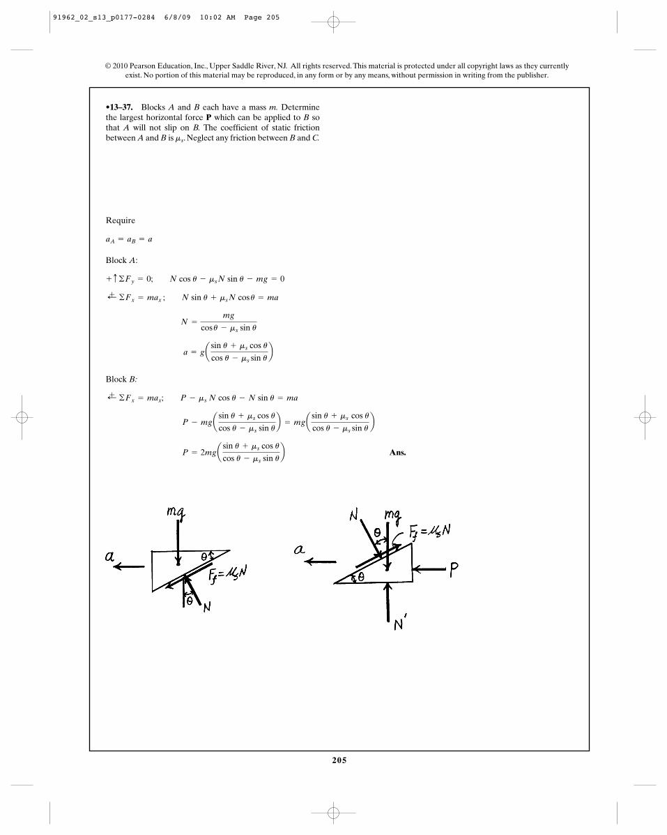
•13–37. Blocks A and B each have a mass m. Determinethe largest horizontal force P which can be applied to B sothat A will not slip on B. The coefficient of static frictionbetween A and B is . Neglect any friction between B and C.ms
Require
Block A:
Block B:
Ans. P = 2mgasin u + ms cos u
cos u - ms sin ub
P - mgasin u + ms cos u
cos u - ms sin ub = mga
sin u + ms cos u
cos u - ms sin ub
;+ ©Fx = max; P - ms N cos u - N sin u = ma
a = gasin u + ms cos u
cos u - ms sin ub
N =
mg
cos u - ms sin u
;+ ©Fx = max ; N sin u + ms N cos u = ma
+ c ©Fy = 0; N cos u - ms N sin u - mg = 0
aA = aB = a
© 2010 Pearson Education, Inc., Upper Saddle River, NJ. All rights reserved. This material is protected under all copyright laws as they currentlyexist. No portion of this material may be reproduced, in any form or by any means, without permission in writing from the publisher.
91962_02_s13_p0177-0284 6/8/09 10:02 AM Page 205
206
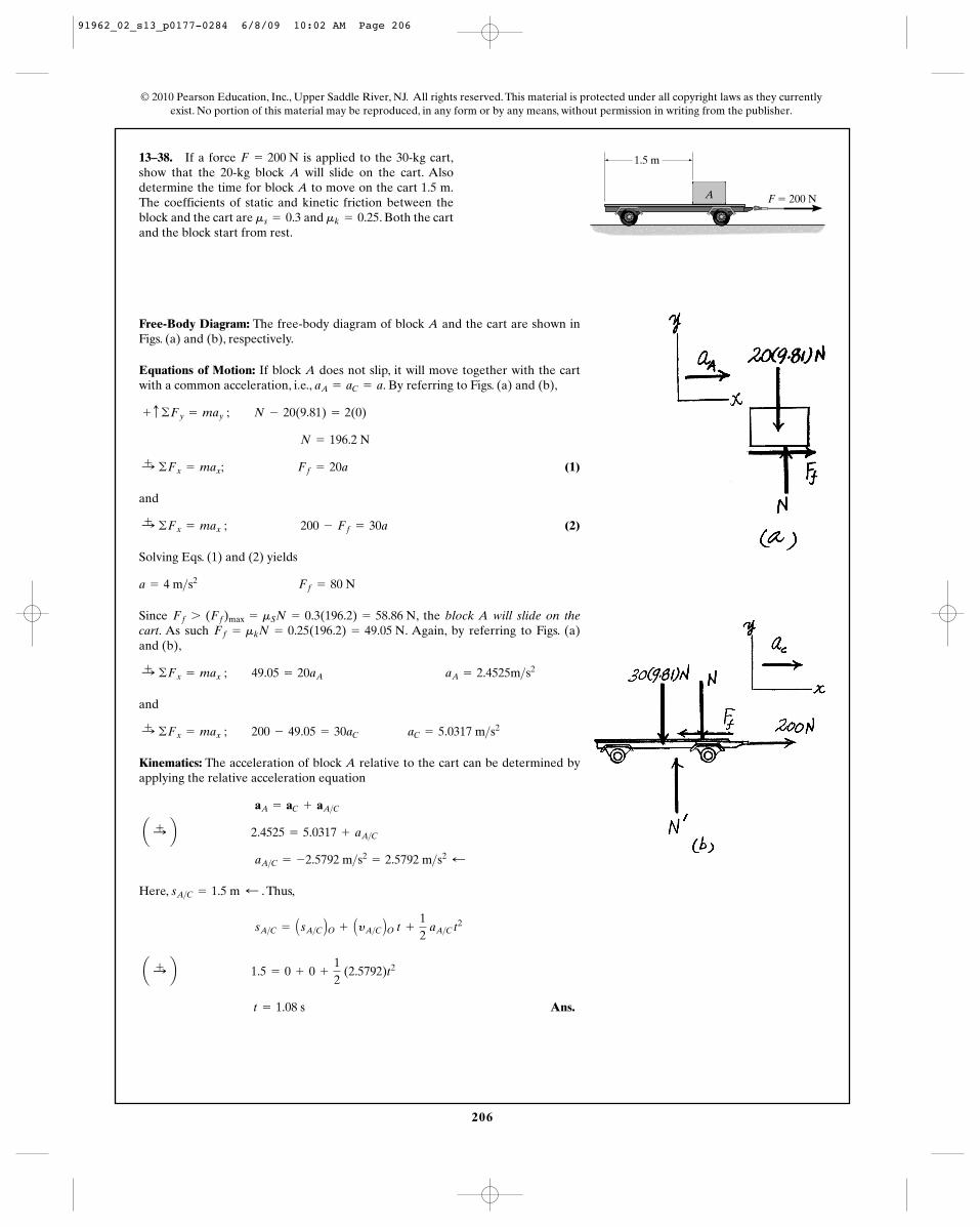
13–38. If a force is applied to the 30-kg cart,show that the 20-kg block A will slide on the cart. Alsodetermine the time for block A to move on the cart 1.5 m.The coefficients of static and kinetic friction between theblock and the cart are and . Both the cartand the block start from rest.
mk = 0.25ms = 0.3
F = 200 N
© 2010 Pearson Education, Inc., Upper Saddle River, NJ. All rights reserved. This material is protected under all copyright laws as they currentlyexist. No portion of this material may be reproduced, in any form or by any means, without permission in writing from the publisher.
Free-Body Diagram: The free-body diagram of block A and the cart are shown inFigs. (a) and (b), respectively.
Equations of Motion: If block A does not slip, it will move together with the cartwith a common acceleration, i.e., . By referring to Figs. (a) and (b),
(1)
and
(2)
Solving Eqs. (1) and (2) yields
Since , the block A will slide on thecart. As such . Again, by referring to Figs. (a)and (b),
and
Kinematics: The acceleration of block A relative to the cart can be determined byapplying the relative acceleration equation
Here, . Thus,
Ans. t = 1.08 s
a :+ b 1.5 = 0 + 0 +
12
(2.5792)t2
sA>C = AsA>C BO + AyA>C BO t +
12
aA>C t2
sA>C = 1.5 m ;
aA>C = -2.5792 m>s2= 2.5792 m>s2 ;
a :+ b 2.4525 = 5.0317 + aA>C
aA = aC + aA>C
:+ ©Fx = max ; 200 - 49.05 = 30aC aC = 5.0317 m>s2
:+ ©Fx = max ; 49.05 = 20aA aA = 2.4525m>s2
Ff = mkN = 0.25(196.2) = 49.05 NFf 7 (Ff)max = mSN = 0.3(196.2) = 58.86 N
a = 4 m>s2 Ff = 80 N
:+ ©Fx = max ; 200 - Ff = 30a
:+ ©Fx = max; Ff = 20a
N = 196.2 N
+ c ©Fy = may ; N - 20(9.81) = 2(0)
aA = aC = a
F � 200 N
1.5 m
A
91962_02_s13_p0177-0284 6/8/09 10:02 AM Page 206
207
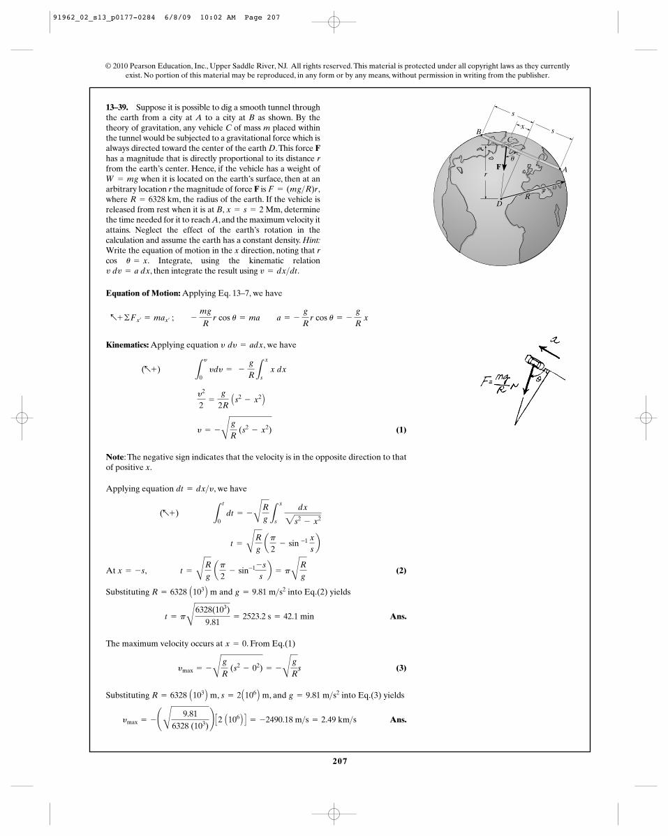
13–39. Suppose it is possible to dig a smooth tunnel throughthe earth from a city at A to a city at B as shown. By thetheory of gravitation, any vehicle C of mass m placed withinthe tunnel would be subjected to a gravitational force which isalways directed toward the center of the earth D.This force Fhas a magnitude that is directly proportional to its distance rfrom the earth’s center. Hence, if the vehicle has a weight of
when it is located on the earth’s surface, then at anarbitrary location r the magnitude of force F is where , the radius of the earth. If the vehicle isreleased from rest when it is at B, , determinethe time needed for it to reach A, and the maximum velocity itattains. Neglect the effect of the earth’s rotation in thecalculation and assume the earth has a constant density. Hint:Write the equation of motion in the x direction, noting that rcos . Integrate, using the kinematic relation
, then integrate the result using .v = dx>dtv dv = a dxu = x
x = s = 2 MmR = 6328 km
F = (mg>R)r,W = mg
Equation of Motion: Applying Eq. 13–7, we have
Kinematics: Applying equation , we have
(1)
Note:The negative sign indicates that the velocity is in the opposite direction to thatof positive x.
Applying equation , we have
At (2)
Substituting and into Eq.(2) yields
Ans.
The maximum velocity occurs at . From Eq.(1)
(3)
Substituting , , and into Eq.(3) yields
Ans.ymax = - ¢C
9.816328 (103)
≤ C2 A106 B D = -2490.18 m>s = 2.49 km>s
g = 9.81 m>s2s = 2 A106 B mR = 6328 A103 B m
ymax = -
C
g
R (s2
- 02) = -
C
g
Rs
x = 0
t = pC
6328(103)
9.81= 2523.2 s = 42.1 min
g = 9.81 m>s2R = 6328 A103 B m
x = -s, t =
CRg
ap
2- sin-1 -s
sb = p
CRg
t =
CRg
ap
2- sin -1 x
sb
(a+) L
t
0 dt = -
CRgL
x
s
dx
2s2- x2
dt = dx>y
y = -
C
g
R (s2
- x2)
y2
2=
g
2R As2
- x2 B
(a+) L
y
0 ydy = -
g
RL
x
s x dx
y dy = adx
a+ ©Fx¿= max¿
; - mg
R r cos u = ma a = -
g
R r cos u = -
g
R x
© 2010 Pearson Education, Inc., Upper Saddle River, NJ. All rights reserved. This material is protected under all copyright laws as they currentlyexist. No portion of this material may be reproduced, in any form or by any means, without permission in writing from the publisher.
F
s
x
CB
A
u
s
DR
r
91962_02_s13_p0177-0284 6/8/09 10:02 AM Page 207
208
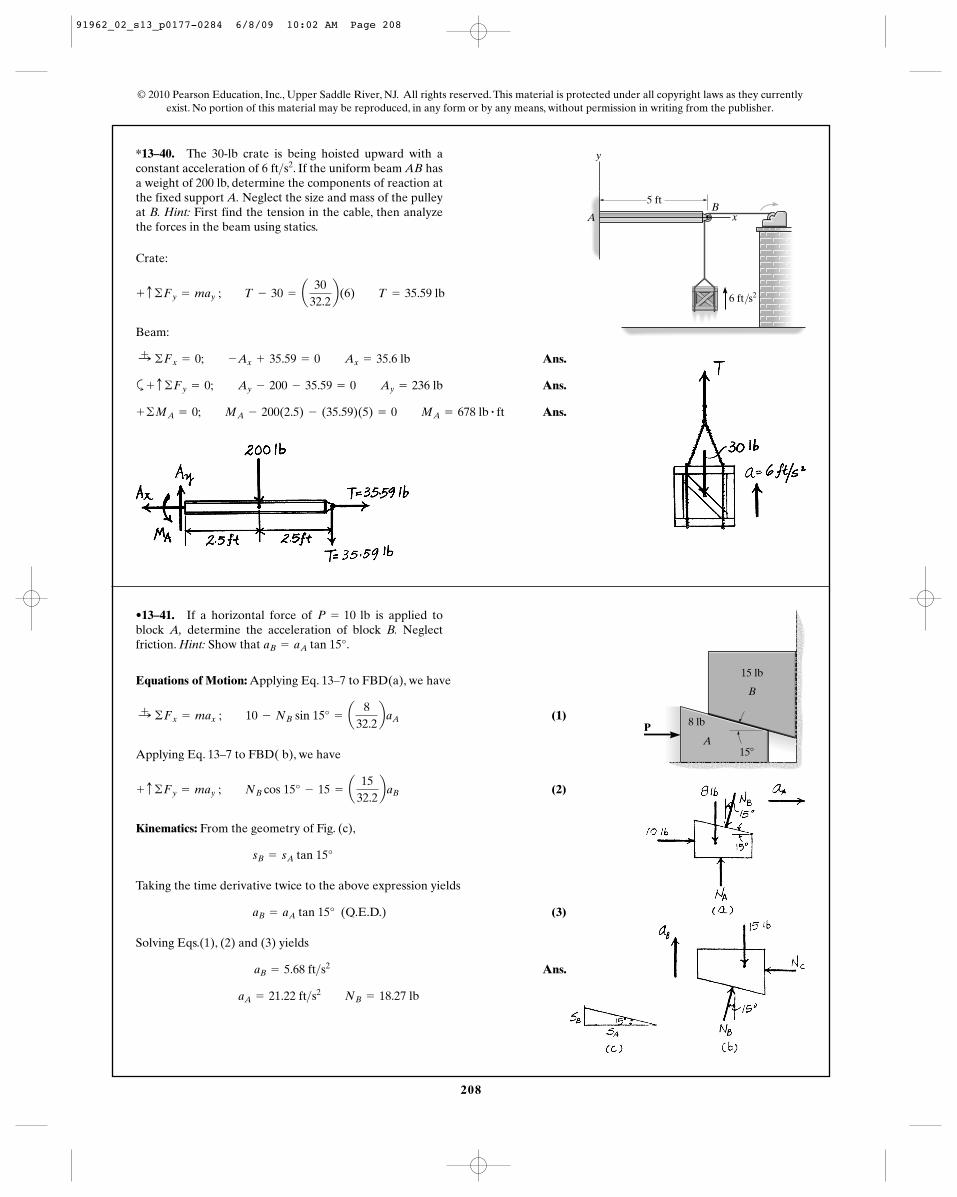
*13–40. The 30-lb crate is being hoisted upward with aconstant acceleration of . If the uniform beam AB hasa weight of 200 lb, determine the components of reaction atthe fixed support A. Neglect the size and mass of the pulleyat B. Hint: First find the tension in the cable, then analyzethe forces in the beam using statics.
6 ft>s2
© 2010 Pearson Education, Inc., Upper Saddle River, NJ. All rights reserved. This material is protected under all copyright laws as they currentlyexist. No portion of this material may be reproduced, in any form or by any means, without permission in writing from the publisher.
Crate:
Beam:
Ans.
a Ans.
Ans.+ ©MA = 0; MA - 200(2.5) - (35.59)(5) = 0 MA = 678 lb # ft
+ c ©Fy = 0; Ay - 200 - 35.59 = 0 Ay = 236 lb
:+ ©Fx = 0; -Ax + 35.59 = 0 Ax = 35.6 lb
+ c ©Fy = may ; T - 30 = a30
32.2b(6) T = 35.59 lb
5 ft
y
xB
A
6 ft/s2
•13–41. If a horizontal force of is applied toblock A, determine the acceleration of block B. Neglectfriction. Hint: Show that .aB = aA tan 15°
P = 10 lb
Equations of Motion: Applying Eq. 13–7 to FBD(a), we have
(1)
Applying Eq. 13–7 to FBD( b), we have
(2)
Kinematics: From the geometry of Fig. (c),
Taking the time derivative twice to the above expression yields
(Q.E.D.) (3)
Solving Eqs.(1), (2) and (3) yields
Ans.
aA = 21.22 ft>s2 NB = 18.27 lb
aB = 5.68 ft>s2
aB = aA tan 15°
sB = sA tan 15°
+ c ©Fy = may ; NB cos 15° - 15 = a15
32.2baB
:+ ©Fx = max ; 10 - NB sin 15° = a8
32.2baA
PA
B
15 lb
8 lb
15�
91962_02_s13_p0177-0284 6/8/09 10:02 AM Page 208
209
© 2010 Pearson Education, Inc., Upper Saddle River, NJ. All rights reserved. This material is protected under all copyright laws as they currentlyexist. No portion of this material may be reproduced, in any form or by any means, without permission in writing from the publisher.
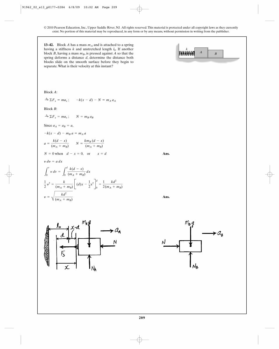
13–42. Block A has a mass and is attached to a springhaving a stiffness k and unstretched length . If anotherblock B, having a mass , is pressed against A so that thespring deforms a distance d, determine the distance bothblocks slide on the smooth surface before they begin toseparate. What is their velocity at this instant?
mB
l0
mA
Block A:
Block B:
Since ,
Ans.
Ans.y =
Ckd2
(mA + mB)
12
y2=
k
(mA + mB) B(d)x -
12
x2Rd
0=
12
kd2
(mA + mB)
L
v
0 y dv =
L
d
0
k(d - x)
(mA + mB) dx
y dy = a dx
N = 0 when d - x = 0, or x = d
a =
k(d - x)
(mA + mB) N =
kmB (d - x)
(mA + mB)
-k(x - d) - mB a = mA a
aA = aB = a
:+ ©Fx = max ; N = mB aB
:+ ©Fx = max ; -k(x - d) - N = mA aA
Ak
B
91962_02_s13_p0177-0284 6/8/09 10:02 AM Page 209
210
© 2010 Pearson Education, Inc., Upper Saddle River, NJ. All rights reserved. This material is protected under all copyright laws as they currentlyexist. No portion of this material may be reproduced, in any form or by any means, without permission in writing from the publisher.
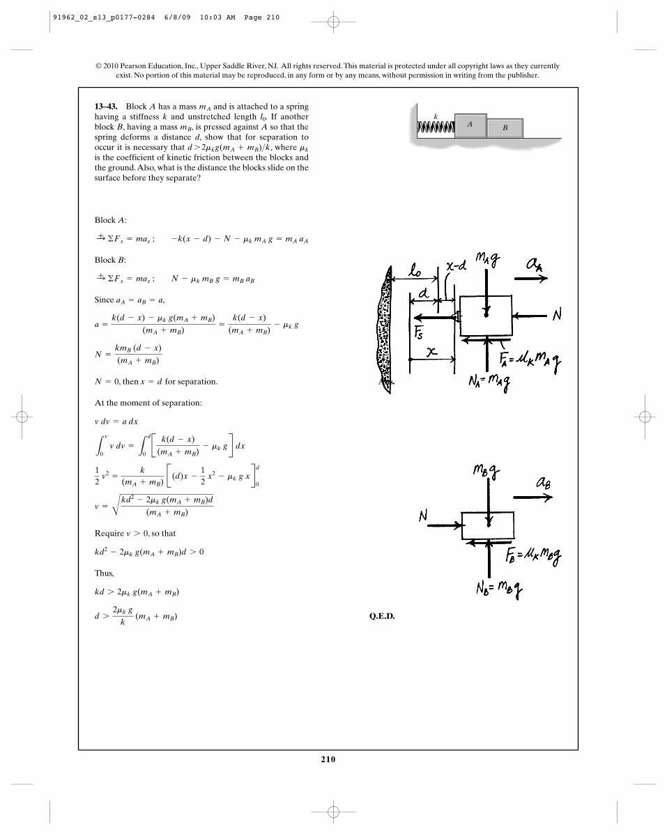
13–43. Block A has a mass and is attached to a springhaving a stiffness k and unstretched length . If anotherblock B, having a mass , is pressed against A so that thespring deforms a distance d, show that for separation tooccur it is necessary that , where is the coefficient of kinetic friction between the blocks andthe ground.Also, what is the distance the blocks slide on thesurface before they separate?
mkd 7 2mkg(mA + mB)>k
mB
l0
mA
Ak
B
Block A:
Block B:
Since ,
, then for separation. Ans.
At the moment of separation:
Require , so that
Thus,
Q.E.D.d 7
2mk g
k (mA + mB)
kd 7 2mk g(mA + mB)
kd2- 2mk g(mA + mB)d 7 0
v 7 0
v =
B
kd2- 2mk g(mA + mB)d
(mA + mB)
12
v2=
k
(mA + mB) B(d)x -
12
x2- mk g xRd
0
L
v
0 v dv =
L
d
0B k(d - x)
(mA + mB)- mk gR dx
v dv = a dx
x = dN = 0
N =
kmB (d - x)
(mA + mB)
a =
k(d - x) - mk g(mA + mB)
(mA + mB)=
k(d - x)
(mA + mB)- mk g
aA = aB = a
:+ ©Fx = max ; N - mk mB g = mB aB
:+ ©Fx = max ; -k(x - d) - N - mk mA g = mA aA
91962_02_s13_p0177-0284 6/8/09 10:03 AM Page 210
211
© 2010 Pearson Education, Inc., Upper Saddle River, NJ. All rights reserved. This material is protected under all copyright laws as they currentlyexist. No portion of this material may be reproduced, in any form or by any means, without permission in writing from the publisher.
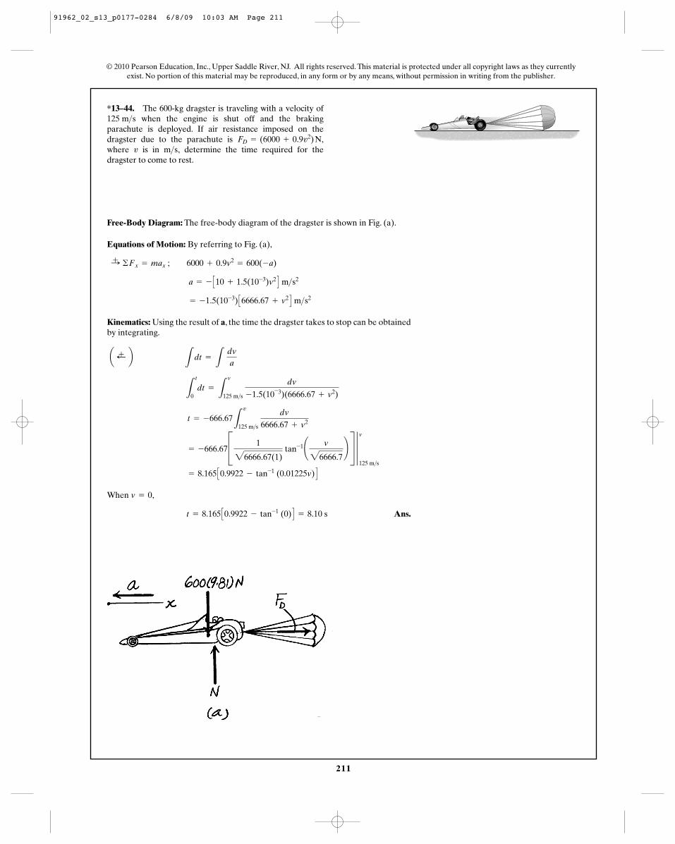
*13–44. The 600-kg dragster is traveling with a velocity ofwhen the engine is shut off and the braking
parachute is deployed. If air resistance imposed on thedragster due to the parachute is ,where is in determine the time required for thedragster to come to rest.
m>s,vFD = (6000 + 0.9v2) N
125 m>s
Free-Body Diagram: The free-body diagram of the dragster is shown in Fig. (a).
Equations of Motion: By referring to Fig. (a),
Kinematics: Using the result of a, the time the dragster takes to stop can be obtainedby integrating.
When ,
Ans.t = 8.165 C0.9922 - tan-1 (0) D = 8.10 s
v = 0
= 8.165 C0.9922 - tan-1 (0.01225v) D
= -666.67C 1
26666.67(1) tan-1¢ v
26666.7≤ S 3
v
125 m>s
t = -666.67L
v
125 m>s
dv
6666.67 + v2
L
t
0dt =
L
v
125 m>s
dv
-1.5(10-3)(6666.67 + v2)
a ;+ b L
dt =
L dva
= -1.5(10-3) C6666.67 + v2 D m>s2
a = - C10 + 1.5(10-3)v2 D m>s2
:+ ©Fx = max ; 6000 + 0.9v2= 600(-a)
91962_02_s13_p0177-0284 6/8/09 10:03 AM Page 211
212
© 2010 Pearson Education, Inc., Upper Saddle River, NJ. All rights reserved. This material is protected under all copyright laws as they currentlyexist. No portion of this material may be reproduced, in any form or by any means, without permission in writing from the publisher.
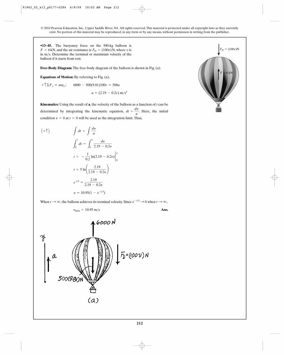
•13–45. The buoyancy force on the 500-kg balloon is, and the air resistance is , where is
in Determine the terminal or maximum velocity of theballoon if it starts from rest.
m>s.vFD = (100v) NF = 6 kN
Free-Body Diagram: The free-body diagram of the balloon is shown in Fig. (a).
Equations of Motion: By referring to Fig. (a),
Kinematics: Using the result of a, the velocity of the balloon as a function of t can be
determined by integrating the kinematic equation, . Here, the initial
condition at will be used as the integration limit. Thus,
When , the balloon achieves its terminal velocity. Since when ,
Ans.ymax = 10.95 m>s
t : qe- t>5 : 0t : q
y = 10.95(1 - e -t>5)
e t>5 =
2.192.19 - 0.2y
t = 5 ln¢ 2.192.19 - 0.2y
≤
t = -
10.2
ln(2.19 - 0.2y) 2 y0
L
t
0 dt =
L
y
0
dy
2.19 - 0.2y
A + c B L
dt =
L dya
t = 0y = 0
dt =
dya
a = (2.19 - 0.2v) m>s2
+ c ©Fy = may ; 6000 - 500(9.81)100v = 500a
F � 6 kN
FD � (100v)N
91962_02_s13_p0177-0284 6/8/09 10:03 AM Page 212
213
© 2010 Pearson Education, Inc., Upper Saddle River, NJ. All rights reserved. This material is protected under all copyright laws as they currentlyexist. No portion of this material may be reproduced, in any form or by any means, without permission in writing from the publisher.
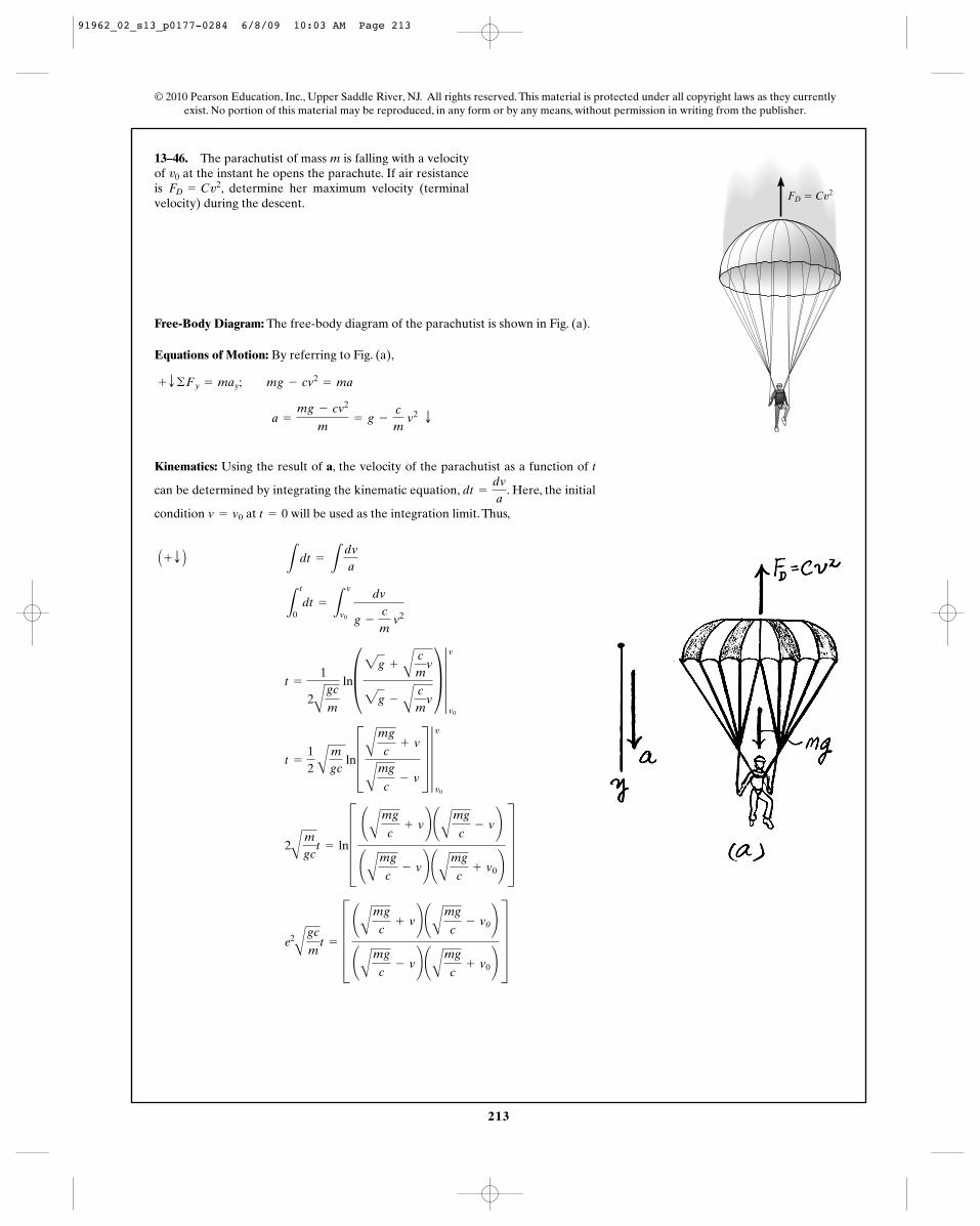
13–46. The parachutist of mass m is falling with a velocityof at the instant he opens the parachute. If air resistanceis , determine her maximum velocity (terminalvelocity) during the descent.
FD = Cv2v0
Free-Body Diagram: The free-body diagram of the parachutist is shown in Fig. (a).
Equations of Motion: By referring to Fig. (a),
Kinematics: Using the result of a, the velocity of the parachutist as a function of t
can be determined by integrating the kinematic equation, . Here, the initial
condition at will be used as the integration limit. Thus,
e2
A
gc
mt = E
¢A
mg
c+ v≤ ¢
A
mg
c- v0≤
¢A
mg
c- v≤ ¢
A
mg
c+ v0≤
U
2A
mgc
t = lnE¢A
mg
c+ v≤ ¢
A
mg
c- v≤
¢A
mg
c- v≤ ¢
A
mg
c+ v0≤
U
t =
12
A
mgc
lnDAmg
c+ v
A
mg
c- v
T 4v
v0
t =
1
2A
gc
m
ln§2g +
A
cm
v
2g -
A
cm
v
¥ 4v
v0
L
t
0dt =
L
v
v0
dv
g -
cm
v2
A + T B L
dt =
Ldva
t = 0v = v0
dt =
dva
a =
mg - cv2
m= g -
cm
v2 T
+ T ©Fy = may; mg - cv2= ma
FD � Cv2
91962_02_s13_p0177-0284 6/8/09 10:03 AM Page 213
214
© 2010 Pearson Education, Inc., Upper Saddle River, NJ. All rights reserved. This material is protected under all copyright laws as they currentlyexist. No portion of this material may be reproduced, in any form or by any means, without permission in writing from the publisher.
When , . Thus, the
terminal velocity of the parachutist is
Ans.
Note: The terminal velocity of the parachutist is independent of the initial velocity .v0
vmax =
A
mg
c
§Amgc
+ v0
A
mgc
- v0
¥e2
A
gc
mt - 1 � 1 + §A
mgc
+ v0
A
mgc
- v0
¥e2
A
gc
mtt : q
v =
A
mg
cD §A
mgc
+ v0
A
mgc
- v0
¥e2
A
gc
mt - 1T
1 + §Amgc
+ v0
A
mgc
- v0
¥e2
A
gc
mt
13–46. Continued
91962_02_s13_p0177-0284 6/8/09 10:03 AM Page 214
215
© 2010 Pearson Education, Inc., Upper Saddle River, NJ. All rights reserved. This material is protected under all copyright laws as they currentlyexist. No portion of this material may be reproduced, in any form or by any means, without permission in writing from the publisher.
Ans. (1)
For minimum escape, require ,
Ans.
when
Escape velocity is
Ans. (2)
From Eq. (1), using the value for from Eq. (2),
Ans.t =
2
3r022g ar
32max - r
320b
1
22gr20
c23
r32 d
rmax
r0
= t
L
r
r0
dr
C
2gr20
r
=
L
t
0dt
v =
dr
dt=
C
2gr20
r
v
vesc = 22gr0
v20 : 2gr0rmax : q
rmax =
2gr20
2gr0 - v20
v20 - 2gr0a1 -
r0
rb = 0
v = 0
v =
Cv0
2- 2gr0a1 -
r0
rb
12
(v2- v2
0) = -gr20 c -
1rd
r
0= gr2
0a1r
-
1r0b
L
v
v0
v dv =
L
r
r0
-gr20
dr
r2
v dv = a dr
a =
gr20
r2
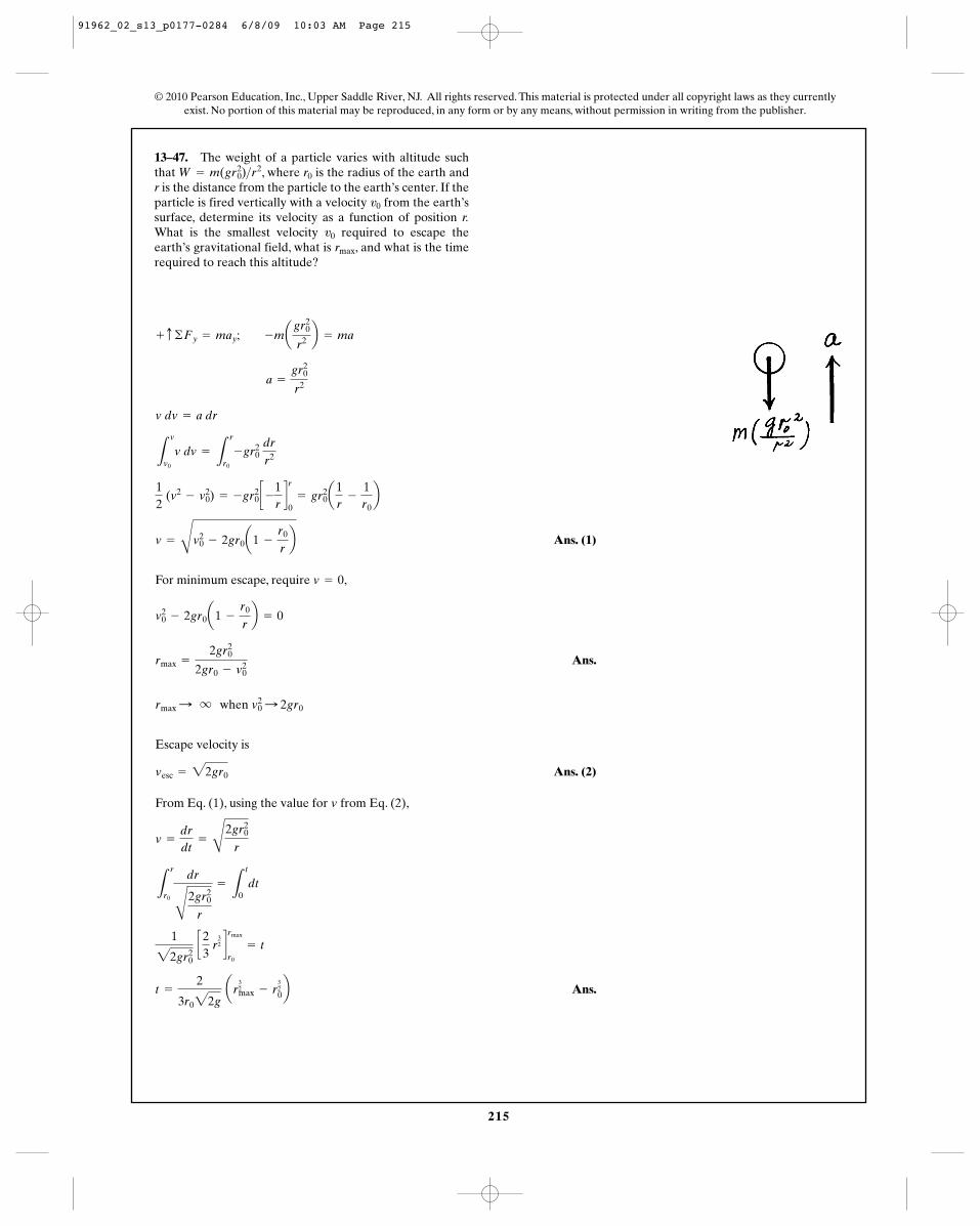
+ c ©Fy = may; -magr2
0
r2 b = ma
13–47. The weight of a particle varies with altitude suchthat , where is the radius of the earth andr is the distance from the particle to the earth’s center. If theparticle is fired vertically with a velocity from the earth’ssurface, determine its velocity as a function of position r.What is the smallest velocity required to escape theearth’s gravitational field, what is , and what is the timerequired to reach this altitude?
rmax
v0
v0
r0W = m(gr20)>r
2
91962_02_s13_p0177-0284 6/8/09 10:03 AM Page 215
216
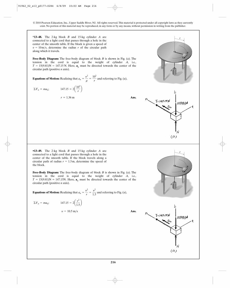
*13–48. The 2-kg block B and 15-kg cylinder A areconnected to a light cord that passes through a hole in thecenter of the smooth table. If the block is given a speed of
, determine the radius r of the circular pathalong which it travels.v = 10 m>s
© 2010 Pearson Education, Inc., Upper Saddle River, NJ. All rights reserved. This material is protected under all copyright laws as they currentlyexist. No portion of this material may be reproduced, in any form or by any means, without permission in writing from the publisher.
Free-Body Diagram: The free-body diagram of block B is shown in Fig. (a). Thetension in the cord is equal to the weight of cylinder A, i.e.,
. Here, an must be directed towards the center of thecircular path (positive n axis).
Equations of Motion: Realizing that and referring to Fig. (a),
Ans. r = 1.36 m
©Fn = man; 147.15 = 2a102
rb
an =
y2
r=
102
r
T = 15(9.81)N = 147.15 N
r
A
v
B
•13–49. The 2-kg block B and 15-kg cylinder A areconnected to a light cord that passes through a hole in thecenter of the smooth table. If the block travels along acircular path of radius , determine the speed ofthe block.
r = 1.5 m
Free-Body Diagram: The free-body diagram of block B is shown in Fig. (a). Thetension in the cord is equal to the weight of cylinder A, i.e.,
. Here, an must be directed towards the center of thecircular path (positive n axis).
Equations of Motion: Realizing that and referring to Fig. (a),
Ans. y = 10.5 m>s
©Fn = man; 147.15 = 2av2
1.5b
an =
y2
r=
y2
1.5
T = 15(9.81)N = 147.15N
r
A
v
B
91962_02_s13_p0177-0284 6/8/09 10:03 AM Page 216

217
© 2010 Pearson Education, Inc., Upper Saddle River, NJ. All rights reserved. This material is protected under all copyright laws as they currentlyexist. No portion of this material may be reproduced, in any form or by any means, without permission in writing from the publisher.
13–50. At the instant shown, the 50-kg projectile travels inthe vertical plane with a speed of . Determinethe tangential component of its acceleration and the radiusof curvature of its trajectory at this instant.r
v = 40 m>s
Free-Body Diagram: The free-body diagram of the projectile is shown in Fig. (a).Here, an must be directed towards the center of curvature of the trajectory (positiven axis).
Equations of Motion: Here, . By referring to Fig. (a),
Ans.
Ans. r = 188 m
+R©Fn = man; 50(9.81) cos 30° = 50a402
rb
at = -4.905 m>s2
+Q©Ft = mat; -50(9.81) sin 30° = 50at
an =
y2
r=
402
r
r
30�
13–51. At the instant shown, the radius of curvature of thevertical trajectory of the 50-kg projectile is .Determine the speed of the projectile at this instant.
r = 200 m
Free-Body Diagram: The free-body diagram of the projectile is shown in Fig. (a).Here, an must be directed towards the center of curvature of the trajectory (positiven axis).
Equations of Motion: Here, . By referring to Fig. (a),
Ans. y = 41.2 m>s
R+ ©Fn = man; 50(9.81) cos 30° = 50ay2
200b
an =
y2
r=
y2
200
r
30�
91962_02_s13_p0177-0284 6/8/09 10:04 AM Page 217
218
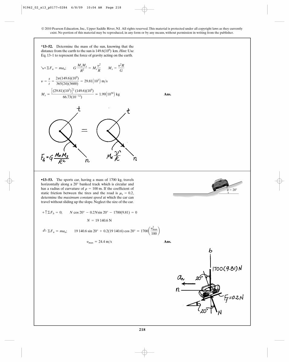
*13–52. Determine the mass of the sun, knowing that thedistance from the earth to the sun is . Hint: UseEq. 13–1 to represent the force of gravity acting on the earth.
149.6(106) km
© 2010 Pearson Education, Inc., Upper Saddle River, NJ. All rights reserved. This material is protected under all copyright laws as they currentlyexist. No portion of this material may be reproduced, in any form or by any means, without permission in writing from the publisher.
Ans.Ms =
C(29.81)(103) D2 (149.6)(109)
66.73(10- 12)= 1.99 A1030 B kg
y =
s
t=
2p(149.6)(109)
365(24)(3600)= 29.81 A103 B m>s
R+ ©Fn = man; G MeMs
R2 = Mey2
R Ms =
y2R
G
•13–53. The sports car, having a mass of 1700 kg, travelshorizontally along a 20° banked track which is circular andhas a radius of curvature of . If the coefficient ofstatic friction between the tires and the road is ,determine the maximum constant speed at which the car cantravel without sliding up the slope. Neglect the size of the car.
ms = 0.2r = 100 m
Ans. ymax = 24.4 m>s
;+ ©Fn = man; 19 140.6 sin 20° + 0.2(19 140.6) cos 20° = 1700ay2
max
100b
N = 19 140.6 N
+ c ©Fb = 0; N cos 20° - 0.2Nsin 20° - 1700(9.81) = 0
� 20�u
91962_02_s13_p0177-0284 6/8/09 10:04 AM Page 218
219
© 2010 Pearson Education, Inc., Upper Saddle River, NJ. All rights reserved. This material is protected under all copyright laws as they currentlyexist. No portion of this material may be reproduced, in any form or by any means, without permission in writing from the publisher.
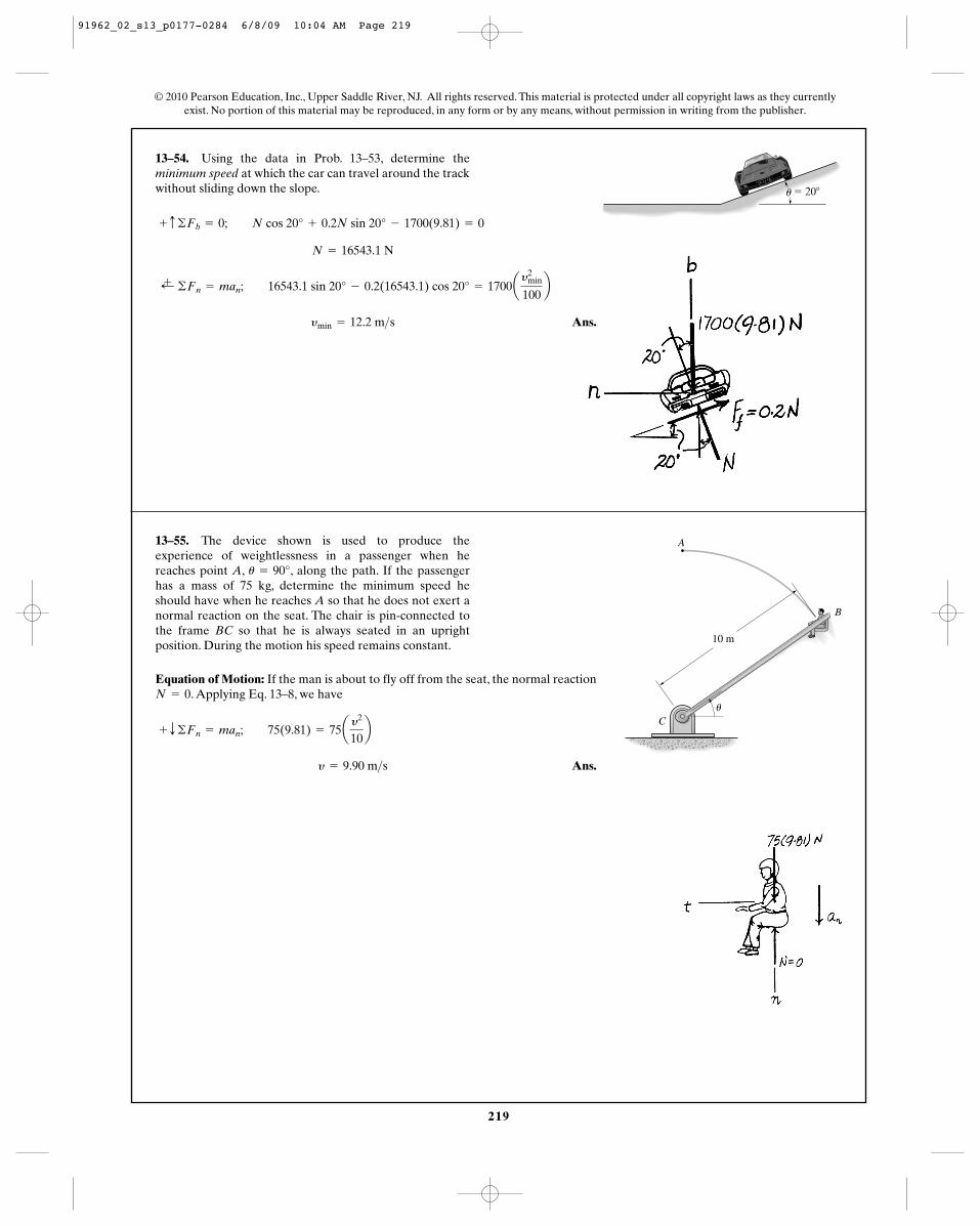
13–54. Using the data in Prob. 13–53, determine theminimum speed at which the car can travel around the trackwithout sliding down the slope. � 20�u
Ans. ymin = 12.2 m>s
;+ ©Fn = man; 16543.1 sin 20° - 0.2(16543.1) cos 20° = 1700ay2
min
100b
N = 16543.1 N
+ c ©Fb = 0; N cos 20° + 0.2N sin 20° - 1700(9.81) = 0
13–55. The device shown is used to produce theexperience of weightlessness in a passenger when hereaches point A, , along the path. If the passengerhas a mass of 75 kg, determine the minimum speed heshould have when he reaches A so that he does not exert anormal reaction on the seat. The chair is pin-connected tothe frame BC so that he is always seated in an uprightposition. During the motion his speed remains constant.
u = 90°
Equation of Motion: If the man is about to fly off from the seat, the normal reaction. Applying Eq. 13–8, we have
Ans. y = 9.90 m>s
+ T ©Fn = man; 75(9.81) = 75ay2
10b
N = 0
B
A
Cu
10 m
91962_02_s13_p0177-0284 6/8/09 10:04 AM Page 219
220
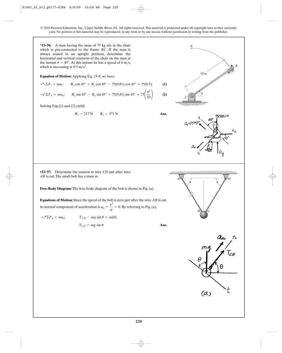
*13–56. A man having the mass of 75 kg sits in the chairwhich is pin-connected to the frame BC. If the man isalways seated in an upright position, determine thehorizontal and vertical reactions of the chair on the man atthe instant . At this instant he has a speed of 6 m s,which is increasing at .0.5 m>s2
>u = 45°
© 2010 Pearson Education, Inc., Upper Saddle River, NJ. All rights reserved. This material is protected under all copyright laws as they currentlyexist. No portion of this material may be reproduced, in any form or by any means, without permission in writing from the publisher.
Equation of Motion: Applying Eq. 13–8, we have
(1)
(2)
Solving Eqs.(1) and (2) yields
Ans.Rx = 217 N Ry = 571 N
+b©Fn = man; Rx sin 45° - Ry sin 45° + 75(9.81) sin 45° = 75¢ 62
10≤
+a©Ft = mat; Rx cos 45° + Ry cos 45° - 75(9.81) cos 45° = 75(0.5)
B
A
Cu
10 m
•13–57. Determine the tension in wire CD just after wireAB is cut. The small bob has a mass m.
Free-Body Diagram: The free-body diagram of the bob is shown in Fig. (a).
Equations of Motion: Since the speed of the bob is zero just after the wire AB is cut,
its normal component of acceleration is . By referring to Fig. (a),
Ans. TCD = mg sin u
+Q©Fn = man; TCD - mg sin u = m(0)
an =
y2
r= 0
A D
B C
u u
91962_02_s13_p0177-0284 6/8/09 10:04 AM Page 220
221
© 2010 Pearson Education, Inc., Upper Saddle River, NJ. All rights reserved. This material is protected under all copyright laws as they currentlyexist. No portion of this material may be reproduced, in any form or by any means, without permission in writing from the publisher.
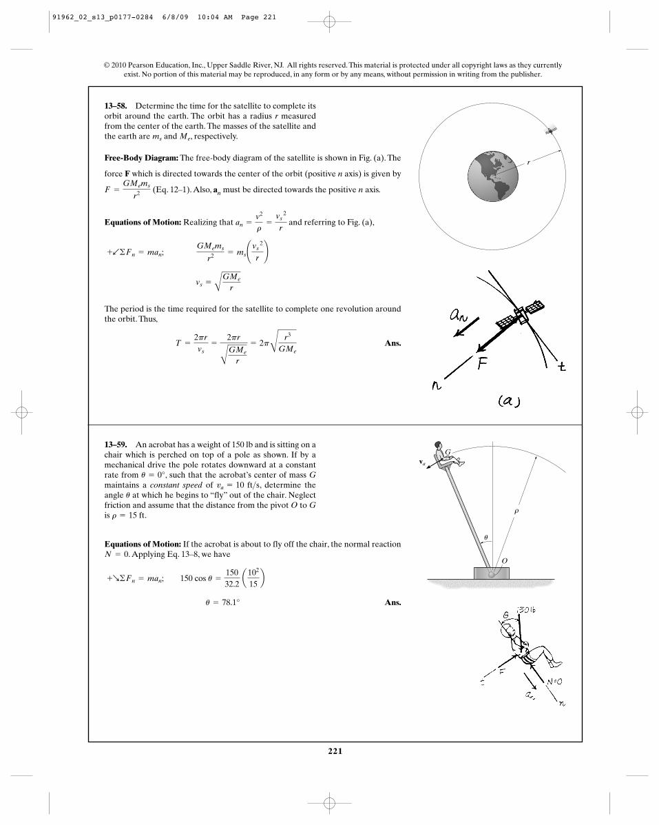
13–58. Determine the time for the satellite to complete itsorbit around the earth. The orbit has a radius r measuredfrom the center of the earth. The masses of the satellite andthe earth are and , respectively.Mems
Free-Body Diagram: The free-body diagram of the satellite is shown in Fig. (a). The
force F which is directed towards the center of the orbit (positive n axis) is given by
(Eq. 12–1). Also, an must be directed towards the positive n axis.
Equations of Motion: Realizing that and referring to Fig. (a),
The period is the time required for the satellite to complete one revolution aroundthe orbit. Thus,
Ans.T =
2pr
vs=
2pr
AGMe
r
= 2pC
r3
GMe
vs =
AGMe
r
+b©Fn = man; GMems
r2 = ms¢vs 2
r≤
an =
v2
r=
vs 2
r
F =
GMems
r2
r
13–59. An acrobat has a weight of 150 lb and is sitting on achair which is perched on top of a pole as shown. If by amechanical drive the pole rotates downward at a constantrate from , such that the acrobat’s center of mass Gmaintains a constant speed of , determine theangle at which he begins to “fly” out of the chair. Neglectfriction and assume that the distance from the pivot O to Gis .r = 15 ft
u
va = 10 ft>su = 0°
Equations of Motion: If the acrobat is about to fly off the chair, the normal reaction. Applying Eq. 13–8, we have
Ans. u = 78.1°
+R©Fn = man; 150 cos u =
15032.2
a102
15b
N = 0
G
O
u
va
91962_02_s13_p0177-0284 6/8/09 10:04 AM Page 221
222
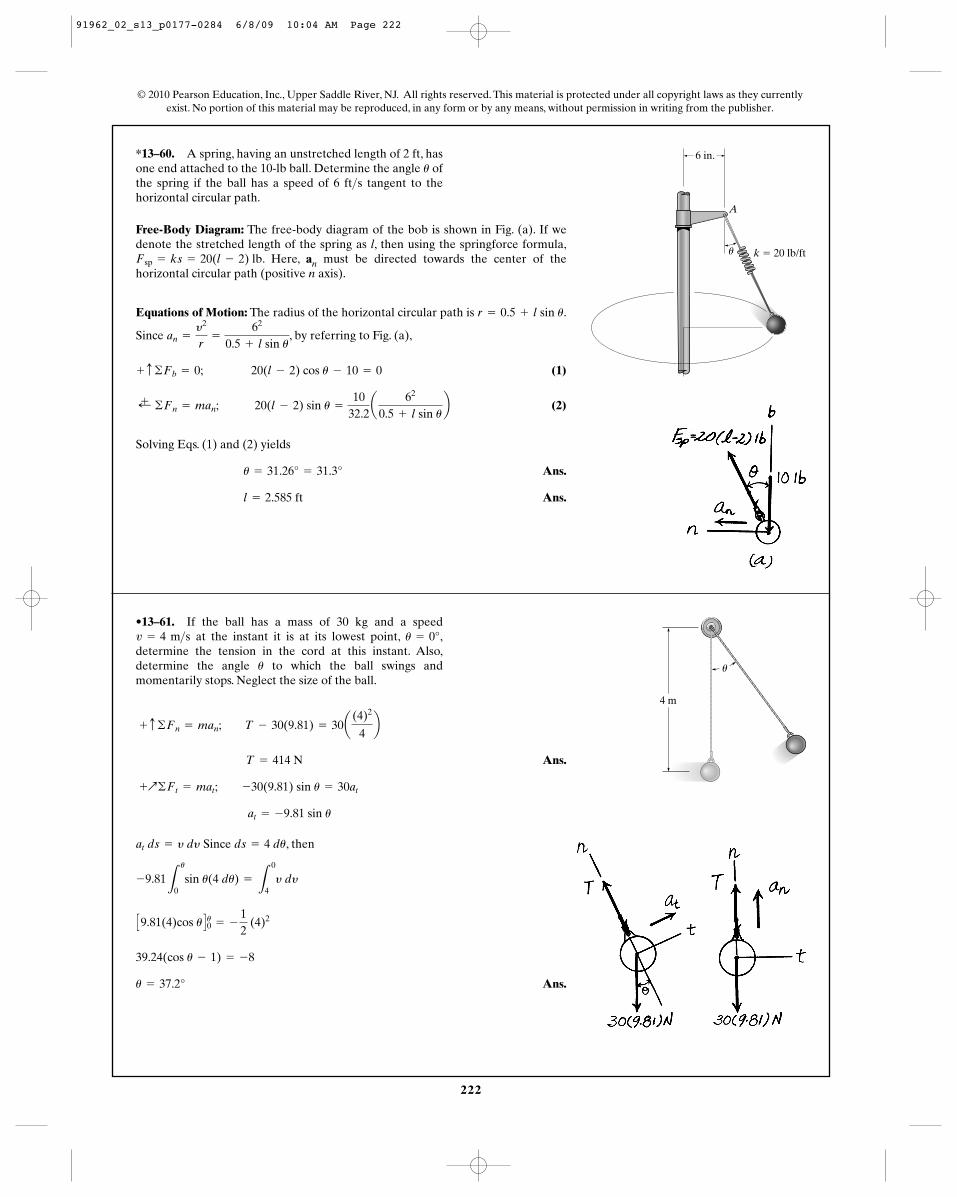
*13–60. A spring, having an unstretched length of 2 ft, hasone end attached to the 10-lb ball. Determine the angle ofthe spring if the ball has a speed of 6 ft s tangent to thehorizontal circular path.
>u
© 2010 Pearson Education, Inc., Upper Saddle River, NJ. All rights reserved. This material is protected under all copyright laws as they currentlyexist. No portion of this material may be reproduced, in any form or by any means, without permission in writing from the publisher.
Free-Body Diagram: The free-body diagram of the bob is shown in Fig. (a). If wedenote the stretched length of the spring as l, then using the springforce formula,
. Here, an must be directed towards the center of thehorizontal circular path (positive n axis).
Equations of Motion: The radius of the horizontal circular path is .
Since , by referring to Fig. (a),
(1)
(2)
Solving Eqs. (1) and (2) yields
Ans.
Ans.l = 2.585 ft
u = 31.26° = 31.3°
;+ ©Fn = man; 20(l - 2) sin u =
1032.2a
62
0.5 + l sin ub
+ c ©Fb = 0; 20(l - 2) cos u - 10 = 0
an =
y2
r=
62
0.5 + l sin u
r = 0.5 + l sin u
Fsp = ks = 20(l - 2) lb
6 in.
A
k � 20 lb/ftu
•13–61. If the ball has a mass of 30 kg and a speedat the instant it is at its lowest point, ,
determine the tension in the cord at this instant. Also,determine the angle to which the ball swings andmomentarily stops. Neglect the size of the ball.
u
u = 0°v = 4 m>s
4 m
u
Ans.
Since , then
Ans.u = 37.2°
39.24(cos u - 1) = -8
C9.81(4)cos u Du0 = - 12
(4)2
-9.81L
u
0sin u(4 du) =
L
0
4y dy
ds = 4 duat ds = y dy
at = -9.81 sin u
+Q©Ft = mat; -30(9.81) sin u = 30at
T = 414 N
+ c ©Fn = man; T - 30(9.81) = 30a(4)2
4b
91962_02_s13_p0177-0284 6/8/09 10:04 AM Page 222
223
© 2010 Pearson Education, Inc., Upper Saddle River, NJ. All rights reserved. This material is protected under all copyright laws as they currentlyexist. No portion of this material may be reproduced, in any form or by any means, without permission in writing from the publisher.
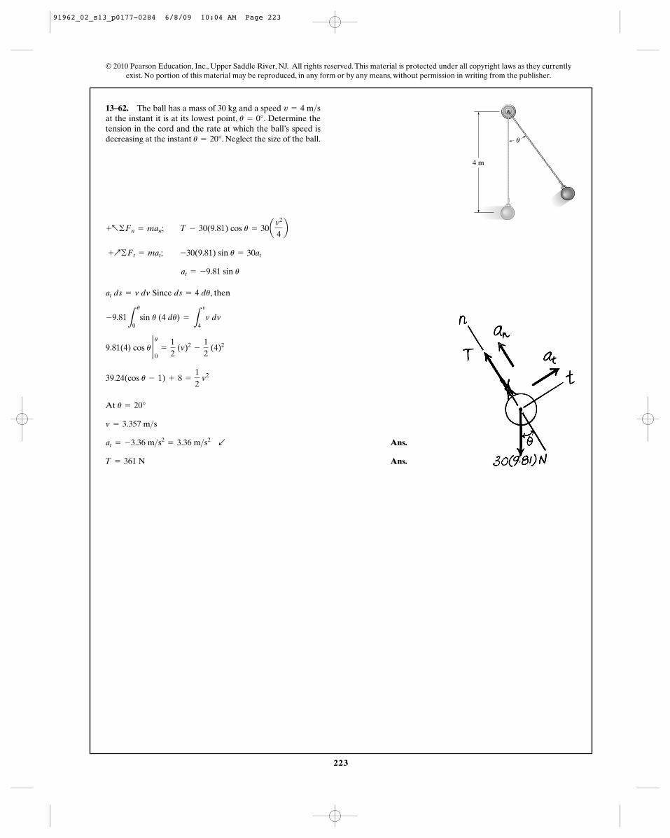
13–62. The ball has a mass of 30 kg and a speed at the instant it is at its lowest point, . Determine thetension in the cord and the rate at which the ball’s speed isdecreasing at the instant . Neglect the size of the ball.u = 20°
u = 0°v = 4 m>s
Since , then
At
Ans.
Ans.T = 361 N
at = -3.36 m>s2= 3.36 m>s2 b
v = 3.357 m>s
u = 20°
39.24(cos u - 1) + 8 =
12
v2
9.81(4) cos u 2 u0
=
12
(v)2-
12
(4)2
-9.81L
u
0sin u (4 du) =
L
v
4v dv
ds = 4 duat ds = v dv
at = -9.81 sin u
+Q©Ft = mat; -30(9.81) sin u = 30at
+a©Fn = man; T - 30(9.81) cos u = 30av2
4b
4 m
u
91962_02_s13_p0177-0284 6/8/09 10:04 AM Page 223
224
© 2010 Pearson Education, Inc., Upper Saddle River, NJ. All rights reserved. This material is protected under all copyright laws as they currentlyexist. No portion of this material may be reproduced, in any form or by any means, without permission in writing from the publisher.
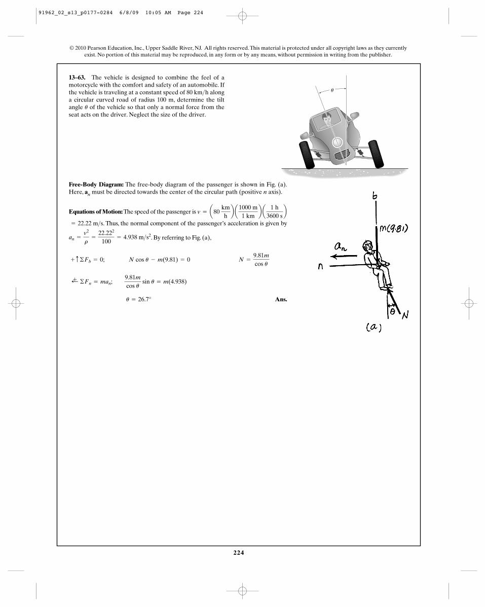
13–63. The vehicle is designed to combine the feel of amotorcycle with the comfort and safety of an automobile. Ifthe vehicle is traveling at a constant speed of 80 km h alonga circular curved road of radius 100 m, determine the tiltangle of the vehicle so that only a normal force from theseat acts on the driver. Neglect the size of the driver.
u
> u
Free-Body Diagram: The free-body diagram of the passenger is shown in Fig. (a).Here, an must be directed towards the center of the circular path (positive n axis).
Equations of Motion: The speed of the passenger is
. Thus, the normal component of the passenger’s acceleration is given by= 22.22 m>s
v = a80 kmhb a
1000 m1 km
b a1 h
3600 sb
. By referring to Fig. (a),
Ans. u = 26.7°
;+ ©Fn = man; 9.81m
cos u sin u = m(4.938)
+ c ©Fb = 0; N cos u - m(9.81) = 0 N =
9.81m
cos u
an =
v2
r=
22.222
100= 4.938 m>s2
91962_02_s13_p0177-0284 6/8/09 10:05 AM Page 224
225
© 2010 Pearson Education, Inc., Upper Saddle River, NJ. All rights reserved. This material is protected under all copyright laws as they currentlyexist. No portion of this material may be reproduced, in any form or by any means, without permission in writing from the publisher.
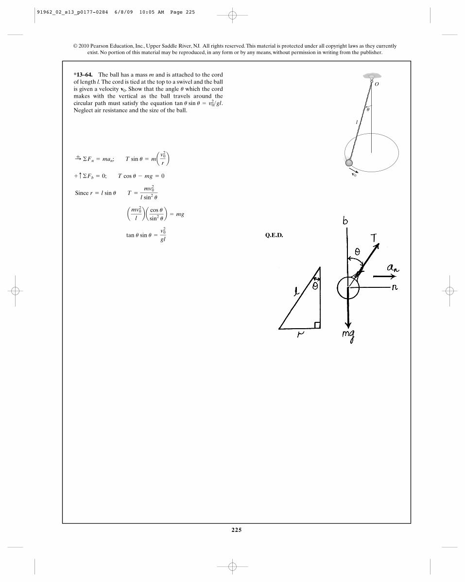
*13–64. The ball has a mass m and is attached to the cordof length l. The cord is tied at the top to a swivel and the ballis given a velocity . Show that the angle which the cordmakes with the vertical as the ball travels around thecircular path must satisfy the equation .Neglect air resistance and the size of the ball.
tan u sin u = v20>gl
uv0
O
u
l
v0
Q.E.D. tan u sin u =
v20
gl
amv2
0
lb a
cos usin2 u
b = mg
Since r = l sin u T =
mv20
l sin2 u
+ c ©Fb = 0; T cos u - mg = 0
:+ ©Fn = man; T sin u = mav0
2
rb
91962_02_s13_p0177-0284 6/8/09 10:05 AM Page 225
226
© 2010 Pearson Education, Inc., Upper Saddle River, NJ. All rights reserved. This material is protected under all copyright laws as they currentlyexist. No portion of this material may be reproduced, in any form or by any means, without permission in writing from the publisher.
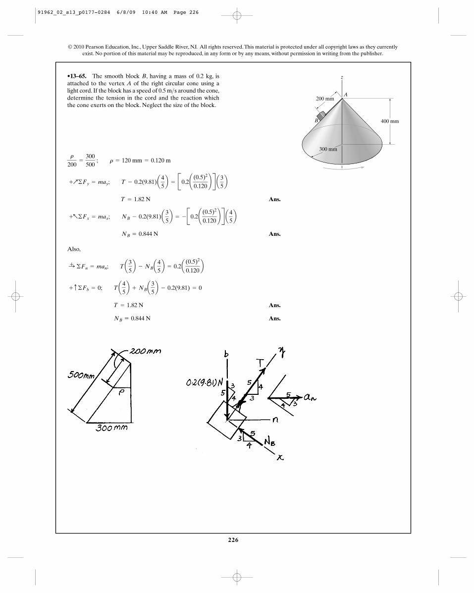
•13–65. The smooth block B, having a mass of 0.2 kg, isattached to the vertex A of the right circular cone using alight cord. If the block has a speed of 0.5 m s around the cone,determine the tension in the cord and the reaction whichthe cone exerts on the block. Neglect the size of the block.
>
Ans.
Ans.
Also,
Ans.
Ans. NB = 0.844 N
T = 1.82 N
+ c ©Fb = 0; Ta45b + NBa
35b - 0.2(9.81) = 0
:+ ©Fn = man; Ta35b - NBa
45b = 0.2a
(0.5)2
0.120b
NB = 0.844 N
+a©Fx = max; NB - 0.2(9.81)a35b = - B0.2¢ (0.5)2
0.120≤ R a4
5b
T = 1.82 N
+Q©Fy = may; T - 0.2(9.81)a45b = B0.2¢ (0.5)2
0.120≤ R a3
5b
r
200=
300500
; r = 120 mm = 0.120 m
z
A
B 400 mm
200 mm
300 mm
91962_02_s13_p0177-0284 6/8/09 10:40 AM Page 226
227
© 2010 Pearson Education, Inc., Upper Saddle River, NJ. All rights reserved. This material is protected under all copyright laws as they currentlyexist. No portion of this material may be reproduced, in any form or by any means, without permission in writing from the publisher.
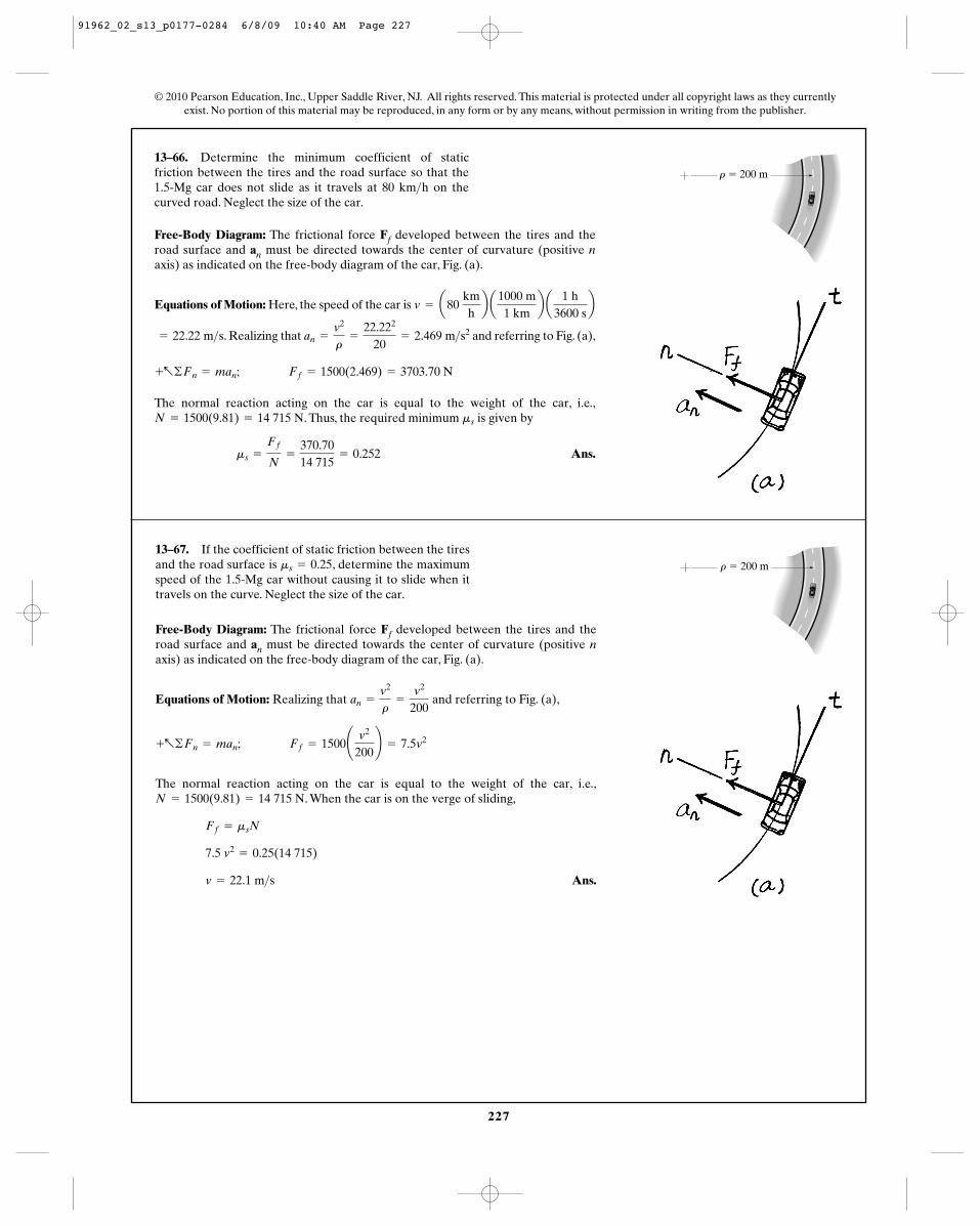
13–66. Determine the minimum coefficient of staticfriction between the tires and the road surface so that the1.5-Mg car does not slide as it travels at 80 km h on thecurved road. Neglect the size of the car.
>
Free-Body Diagram: The frictional force Ff developed between the tires and theroad surface and an must be directed towards the center of curvature (positive naxis) as indicated on the free-body diagram of the car, Fig. (a).
Equations of Motion: Here, the speed of the car is v = a80 kmhb a
1000 m1 km
b a1 h
3600 sb
r � 200 m
. Realizing that and referring to Fig. (a),
The normal reaction acting on the car is equal to the weight of the car, i.e.,. Thus, the required minimum is given by
Ans.ms =
Ff
N=
370.7014 715
= 0.252
msN = 1500(9.81) = 14 715 N
+a©Fn = man; Ff = 1500(2.469) = 3703.70 N
an =
v2
r=
22.222
20= 2.469 m>s2
= 22.22 m>s
13–67. If the coefficient of static friction between the tiresand the road surface is , determine the maximumspeed of the 1.5-Mg car without causing it to slide when ittravels on the curve. Neglect the size of the car.
ms = 0.25
Free-Body Diagram: The frictional force Ff developed between the tires and theroad surface and an must be directed towards the center of curvature (positive naxis) as indicated on the free-body diagram of the car, Fig. (a).
Equations of Motion: Realizing that and referring to Fig. (a),
The normal reaction acting on the car is equal to the weight of the car, i.e.,. When the car is on the verge of sliding,
Ans.v = 22.1 m>s
7.5 v2= 0.25(14 715)
Ff = msN
N = 1500(9.81) = 14 715 N
+a©Fn = man; Ff = 1500¢ v2
200≤ = 7.5v2
an =
v2
r=
v2
200
r � 200 m
91962_02_s13_p0177-0284 6/8/09 10:40 AM Page 227
228
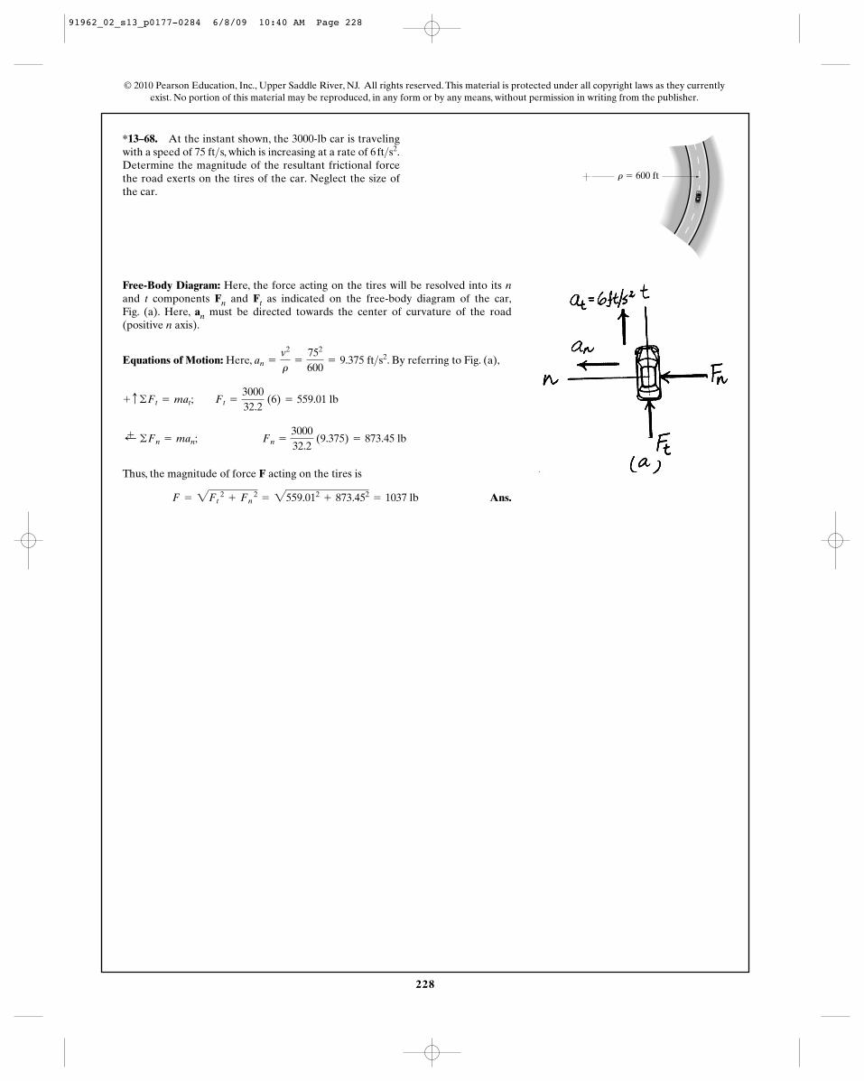
*13–68. At the instant shown, the 3000-lb car is travelingwith a speed of 75 ft s, which is increasing at a rate of Determine the magnitude of the resultant frictional forcethe road exerts on the tires of the car. Neglect the size ofthe car.
6 ft>s2.>
© 2010 Pearson Education, Inc., Upper Saddle River, NJ. All rights reserved. This material is protected under all copyright laws as they currentlyexist. No portion of this material may be reproduced, in any form or by any means, without permission in writing from the publisher.
Free-Body Diagram: Here, the force acting on the tires will be resolved into its nand t components Fn and Ft as indicated on the free-body diagram of the car,Fig. (a). Here, an must be directed towards the center of curvature of the road(positive n axis).
Equations of Motion: Here, . By referring to Fig. (a),
Thus, the magnitude of force F acting on the tires is
Ans.F = 2Ft 2
+ Fn 2
= 2559.012+ 873.452
= 1037 lb
;+ ©Fn = man; Fn =
300032.2
(9.375) = 873.45 lb
+ c ©Ft = mat; Ft =
300032.2
(6) = 559.01 lb
an =
v2
r=
752
600= 9.375 ft>s2
r � 600 ft
91962_02_s13_p0177-0284 6/8/09 10:40 AM Page 228
229
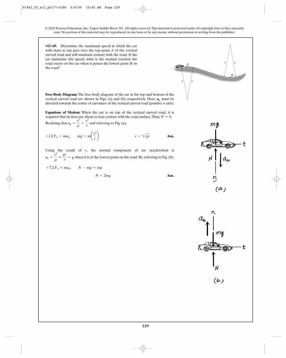
•13–69. Determine the maximum speed at which the carwith mass m can pass over the top point A of the verticalcurved road and still maintain contact with the road. If thecar maintains this speed, what is the normal reaction theroad exerts on the car when it passes the lowest point B onthe road?
© 2010 Pearson Education, Inc., Upper Saddle River, NJ. All rights reserved. This material is protected under all copyright laws as they currentlyexist. No portion of this material may be reproduced, in any form or by any means, without permission in writing from the publisher.
r r
r r
A
B
Free-Body Diagram: The free-body diagram of the car at the top and bottom of thevertical curved road are shown in Figs. (a) and (b), respectively. Here, an must bedirected towards the center of curvature of the vertical curved road (positive n axis).
Equations of Motion: When the car is on top of the vertical curved road, it isrequired that its tires are about to lose contact with the road surface. Thus, .
Realizing that and referring to Fig. (a),
Ans.
Using the result of , the normal component of car acceleration is
when it is at the lowest point on the road. By referring to Fig. (b),
Ans. N = 2mg
+ c ©Fn = man; N - mg = mg
an =
v2
r=
gr
r= g
v
+ T ©Fn = man; mg = m¢v2
r≤ v = 2gr
an =
v2
r=
v2
r
N = 0
91962_02_s13_p0177-0284 6/8/09 10:40 AM Page 229
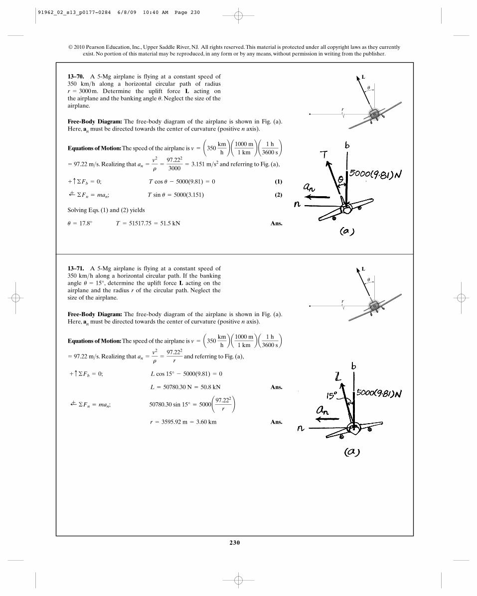
230
13–70. A 5-Mg airplane is flying at a constant speed of 350 km h along a horizontal circular path of radius
. Determine the uplift force L acting on the airplane and the banking angle . Neglect the size of theairplane.
u
r = 3000 m>
© 2010 Pearson Education, Inc., Upper Saddle River, NJ. All rights reserved. This material is protected under all copyright laws as they currentlyexist. No portion of this material may be reproduced, in any form or by any means, without permission in writing from the publisher.
Free-Body Diagram: The free-body diagram of the airplane is shown in Fig. (a).Here, an must be directed towards the center of curvature (positive n axis).
Equations of Motion: The speed of the airplane is v = ¢350 kmh≤ ¢1000 m
1 km≤ ¢ 1 h
3600 s≤
r
L
u
. Realizing that and referring to Fig. (a),
(1)
(2)
Solving Eqs. (1) and (2) yields
Ans.u = 17.8° T = 51517.75 = 51.5 kN
;+ ©Fn = man; T sin u = 5000(3.151)
+ c ©Fb = 0; T cos u - 5000(9.81) = 0
an =
v2
r=
97.222
3000= 3.151 m>s2
= 97.22 m>s
13–71. A 5-Mg airplane is flying at a constant speed of 350 km h along a horizontal circular path. If the bankingangle , determine the uplift force L acting on theairplane and the radius r of the circular path. Neglect thesize of the airplane.
u = 15°>
Free-Body Diagram: The free-body diagram of the airplane is shown in Fig. (a).Here, an must be directed towards the center of curvature (positive n axis).
Equations of Motion: The speed of the airplane is v = a350 kmhb a
1000 m1 km
b a1 h
3600 sb
r
L
u
. Realizing that and referring to Fig. (a),
Ans.
Ans. r = 3595.92 m = 3.60 km
;+ ©Fn = man; 50780.30 sin 15° = 5000¢97.222
r≤
L = 50780.30 N = 50.8 kN
+ c ©Fb = 0; L cos 15° - 5000(9.81) = 0
an =
v2
r=
97.222
r= 97.22 m>s
91962_02_s13_p0177-0284 6/8/09 10:40 AM Page 230
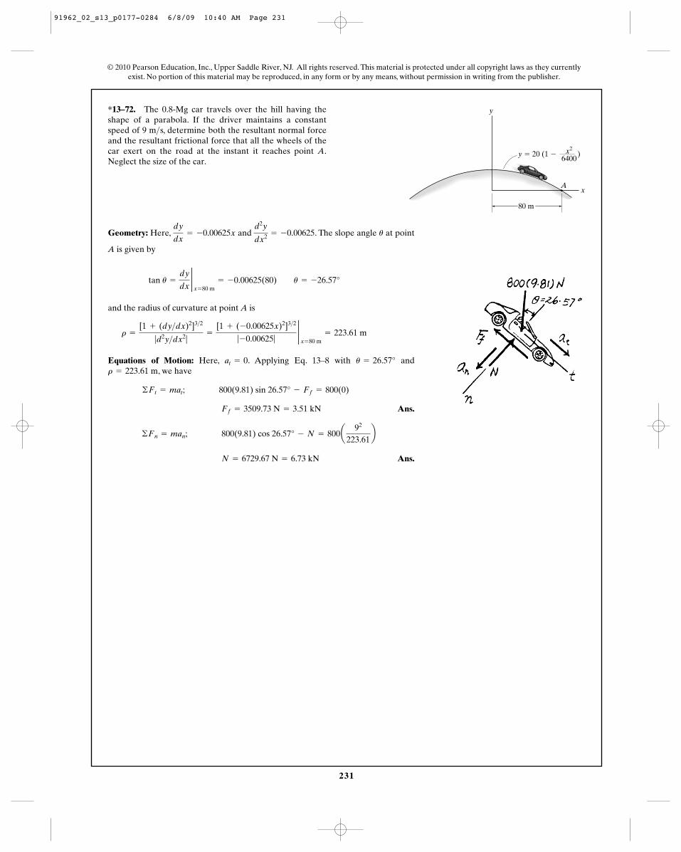
231
© 2010 Pearson Education, Inc., Upper Saddle River, NJ. All rights reserved. This material is protected under all copyright laws as they currentlyexist. No portion of this material may be reproduced, in any form or by any means, without permission in writing from the publisher.
*13–72. The 0.8-Mg car travels over the hill having theshape of a parabola. If the driver maintains a constantspeed of 9 m s, determine both the resultant normal forceand the resultant frictional force that all the wheels of thecar exert on the road at the instant it reaches point A.Neglect the size of the car.
>
Geometry: Here, and . The slope angle at point
A is given by
and the radius of curvature at point A is
Equations of Motion: Here, . Applying Eq. 13–8 with and, we have
Ans.
Ans. N = 6729.67 N = 6.73 kN
©Fn = man; 800(9.81) cos 26.57° - N = 800a92
223.61b
Ff = 3509.73 N = 3.51 kN
©Ft = mat; 800(9.81) sin 26.57° - Ff = 800(0)
r = 223.61 mu = 26.57°at = 0
r =
[1 + (dy>dx)2]3>2
|d2y>dx2|=
[1 + (-0.00625x)2]3>2
|-0.00625|2x = 80 m
= 223.61 m
tan u =
dy
dx2x = 80 m
= -0.00625(80) u = -26.57°
ud2y
dx2 = -0.00625dy
dx= -0.00625x
y
Ax
y � 20 (1 � )
80 m
x2
6400
91962_02_s13_p0177-0284 6/8/09 10:40 AM Page 231
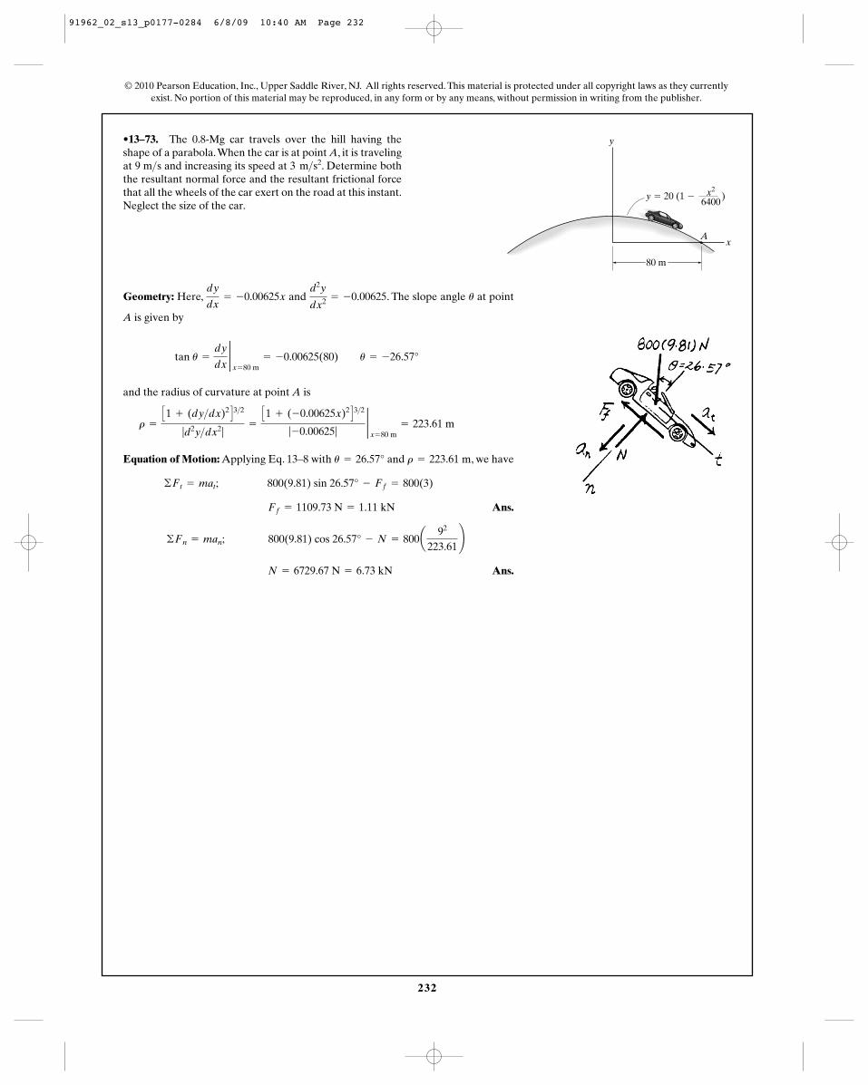
232
© 2010 Pearson Education, Inc., Upper Saddle River, NJ. All rights reserved. This material is protected under all copyright laws as they currentlyexist. No portion of this material may be reproduced, in any form or by any means, without permission in writing from the publisher.
•13–73. The 0.8-Mg car travels over the hill having theshape of a parabola.When the car is at point A, it is travelingat 9 m s and increasing its speed at . Determine boththe resultant normal force and the resultant frictional forcethat all the wheels of the car exert on the road at this instant.Neglect the size of the car.
3 m>s2>
Geometry: Here, and . The slope angle at point
A is given by
and the radius of curvature at point A is
Equation of Motion: Applying Eq. 13–8 with and , we have
Ans.
Ans. N = 6729.67 N = 6.73 kN
©Fn = man; 800(9.81) cos 26.57° - N = 800a92
223.61≤
Ff = 1109.73 N = 1.11 kN
©Ft = mat; 800(9.81) sin 26.57° - Ff = 800(3)
r = 223.61 mu = 26.57°
r =
C1 + (dy>dx)2 D3>2
|d2y>dx2|=
C1 + (-0.00625x)2 D3>2
|-0.00625|2x = 80 m
= 223.61 m
tan u =
dy
dx2x = 80 m
= -0.00625(80) u = -26.57°
ud2y
dx2 = -0.00625dy
dx= -0.00625x
y
Ax
y � 20 (1 � )
80 m
x2
6400
91962_02_s13_p0177-0284 6/8/09 10:40 AM Page 232
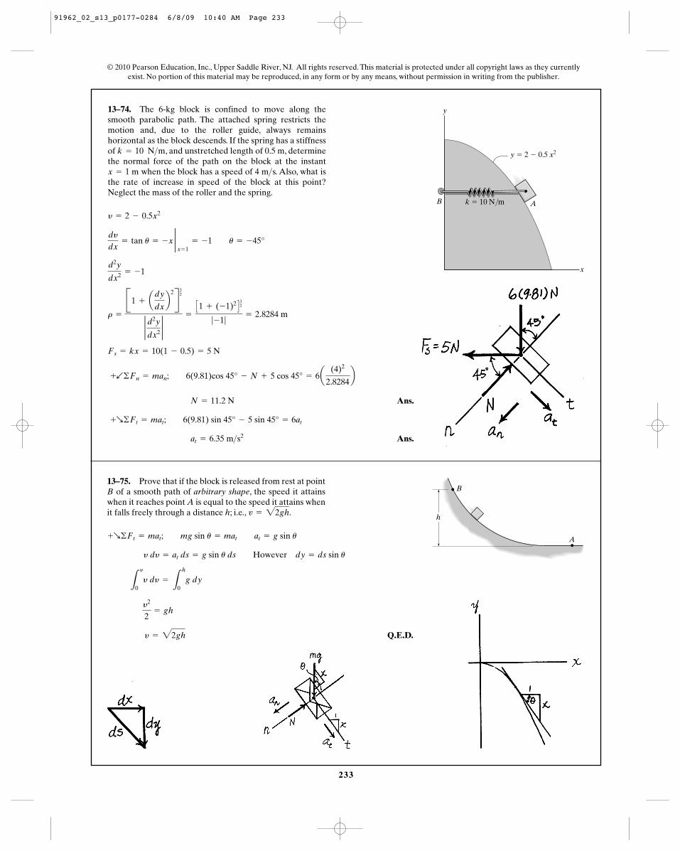
233
© 2010 Pearson Education, Inc., Upper Saddle River, NJ. All rights reserved. This material is protected under all copyright laws as they currentlyexist. No portion of this material may be reproduced, in any form or by any means, without permission in writing from the publisher.
13–74. The 6-kg block is confined to move along thesmooth parabolic path. The attached spring restricts themotion and, due to the roller guide, always remainshorizontal as the block descends. If the spring has a stiffnessof , and unstretched length of 0.5 m, determinethe normal force of the path on the block at the instant
when the block has a speed of 4 m s. Also, what isthe rate of increase in speed of the block at this point?Neglect the mass of the roller and the spring.
>x = 1 m
k = 10 N>m
Ans.
Ans. at = 6.35 m>s2
+R©Ft = mat; 6(9.81) sin 45° - 5 sin 45° = 6at
N = 11.2 N
+b©Fn = man; 6(9.81)cos 45° - N + 5 cos 45° = 6a(4)2
2.8284b
Fs = kx = 10(1 - 0.5) = 5 N
r =
B1 + ady
dxb
2R32
2 d2y
dx22
=
C1 + (-1)2 D32
|-1|= 2.8284 m
d2y
dx2 = -1
dy
dx= tan u = -x 2
x = 1= -1 u = -45°
y = 2 - 0.5x2
y
y � 2 � 0.5 x2
k � 10 N/m
x
B A
13–75. Prove that if the block is released from rest at pointB of a smooth path of arbitrary shape, the speed it attainswhen it reaches point A is equal to the speed it attains whenit falls freely through a distance h; i.e., v = 22gh.
Q.E.D. y = 22gh
y2
2= gh
L
y
0y dy =
L
h
0g dy
y dy = at ds = g sin u ds However dy = ds sin u
+R©Ft = mat; mg sin u = mat at = g sin u A
B
h
91962_02_s13_p0177-0284 6/8/09 10:40 AM Page 233
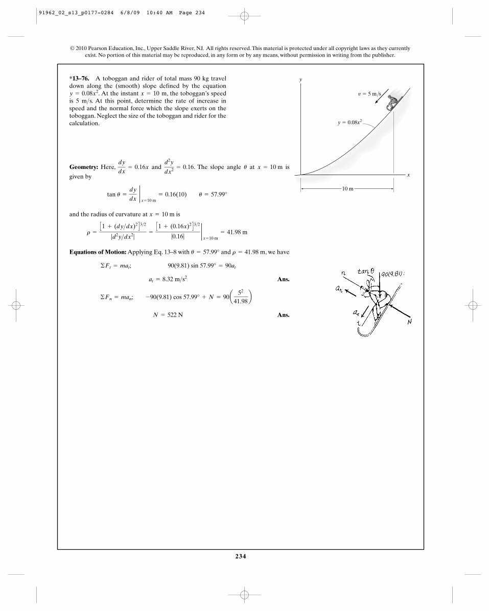
234
*13–76. A toboggan and rider of total mass 90 kg traveldown along the (smooth) slope defined by the equation
. At the instant , the toboggan’s speedis 5 m s. At this point, determine the rate of increase inspeed and the normal force which the slope exerts on thetoboggan. Neglect the size of the toboggan and rider for thecalculation.
>x = 10 my = 0.08x2
© 2010 Pearson Education, Inc., Upper Saddle River, NJ. All rights reserved. This material is protected under all copyright laws as they currentlyexist. No portion of this material may be reproduced, in any form or by any means, without permission in writing from the publisher.
Geometry: Here, and . The slope angle at is
given by
and the radius of curvature at is
Equations of Motion: Applying Eq. 13–8 with and , we have
Ans.
Ans. N = 522 N
©Fn = man; -90(9.81) cos 57.99° + N = 90a52
41.98b
at = 8.32 m>s2
©Ft = mat; 90(9.81) sin 57.99° = 90at
r = 41.98 mu = 57.99°
r =
C1 + (dy>dx)2 D3>2
|d2y>dx2|=
C1 + (0.16x)2 D3>2
|0.16|2x = 10 m
= 41.98 m
x = 10 m
tan u =
dy
dx 2
x = 10 m= 0.16(10) u = 57.99°
x = 10 mud2y
dx2 = 0.16dy
dx= 0.16x
y � 0.08x2
v � 5 m/s
y
x
10 m
91962_02_s13_p0177-0284 6/8/09 10:40 AM Page 234
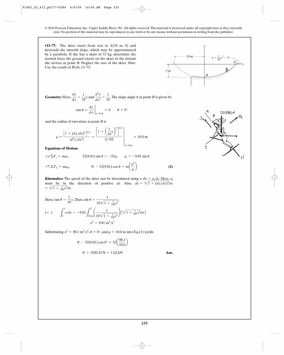
235
•13–77. The skier starts from rest at A(10 m, 0) anddescends the smooth slope, which may be approximatedby a parabola. If she has a mass of 52 kg, determine thenormal force the ground exerts on the skier at the instantshe arrives at point B. Neglect the size of the skier. Hint:Use the result of Prob. 13–75.
Geometry: Here, and . The slope angle at point B is given by
and the radius of curvature at point B is
Equations of Motion:
(1)
Kinematics: The speed of the skier can be determined using . Here, atmust be in the direction of positive ds. Also,
Here, . Then, .
Substituting , , and into Eq.(1) yields
Ans. N = 1020.24 N = 1.02 kN
N - 52(9.81) cos 0° = 52a98.110.0b
r = 10.0 mu = 0°y2= 98.1 m2>s2
y2= 9.81 m2>s2
(+ ) L
y
0y dy = -9.81
L
0
10 m¢ x
1021 +1
100x2≤ A21 +
1100x2dx B
sin u =
x
1021 +1
100x2tan u =
110
x
= 21 +1
100x2dxds = 21 + (dy>dx)2dxy dy = at ds
+a©Fn = man; N - 52(9.81) cos u = may2
rb
+b©Ft = mat; 52(9.81) sin u = -52at at = -9.81 sin u
r =
C1 + (dy>dx)2 D3>2
|d2y>dx2|=
c1 + a1
10xb
2
d3>2
|1>10| 4
x = 0 m
= 10.0 m
tan u =
dy
dx 2
x = 0 m= 0 u = 0°
ud2y
dx2 =
110
dy
dx=
110
x
© 2010 Pearson Education, Inc., Upper Saddle River, NJ. All rights reserved. This material is protected under all copyright laws as they currentlyexist. No portion of this material may be reproduced, in any form or by any means, without permission in writing from the publisher.
10 m
5 m
y
B
Ax
y � x2 � 51––20
91962_02_s13_p0177-0284 6/8/09 10:40 AM Page 235
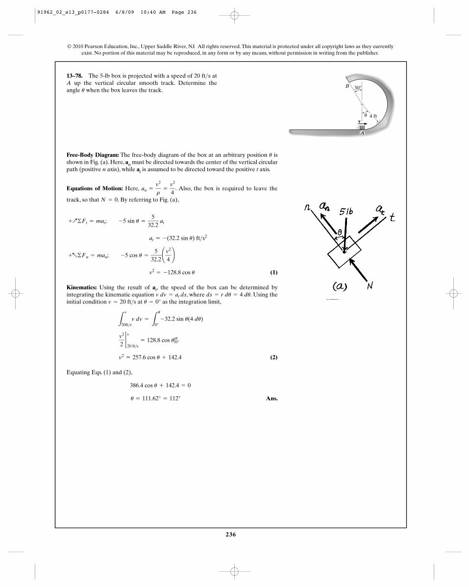
236
13–78. The 5-lb box is projected with a speed of 20 ft s atA up the vertical circular smooth track. Determine theangle when the box leaves the track.u
>
© 2010 Pearson Education, Inc., Upper Saddle River, NJ. All rights reserved. This material is protected under all copyright laws as they currentlyexist. No portion of this material may be reproduced, in any form or by any means, without permission in writing from the publisher.
Free-Body Diagram: The free-body diagram of the box at an arbitrary position isshown in Fig. (a). Here, an must be directed towards the center of the vertical circularpath (positive n axis), while at is assumed to be directed toward the positive t axis.
Equations of Motion: Here, . Also, the box is required to leave the
track, so that . By referring to Fig. (a),
(1)
Kinematics: Using the result of at, the speed of the box can be determined byintegrating the kinematic equation , where . Using theinitial condition at as the integration limit,
(2)
Equating Eqs. (1) and (2),
Ans.u = 111.62° = 112°
386.4 cos u + 142.4 = 0
v2= 257.6 cos u + 142.4
v2
22 v20 ft>s
= 128.8 cos u|u0°
L
v
20ft>sv dv =
L
u
0°-32.2 sin u(4 du)
u = 0°v = 20 ft>sds = r du = 4 duv dv = at ds
v2= -128.8 cos u
+a©Fn = man; -5 cos u =
532.2¢v2
4≤
at = -(32.2 sin u) ft>s2
+Q©Ft = mat; -5 sin u =
532.2
at
N = 0
an =
v2
r=
v2
4
u
B
4 ftv
A
30�
u
91962_02_s13_p0177-0284 6/8/09 10:40 AM Page 236
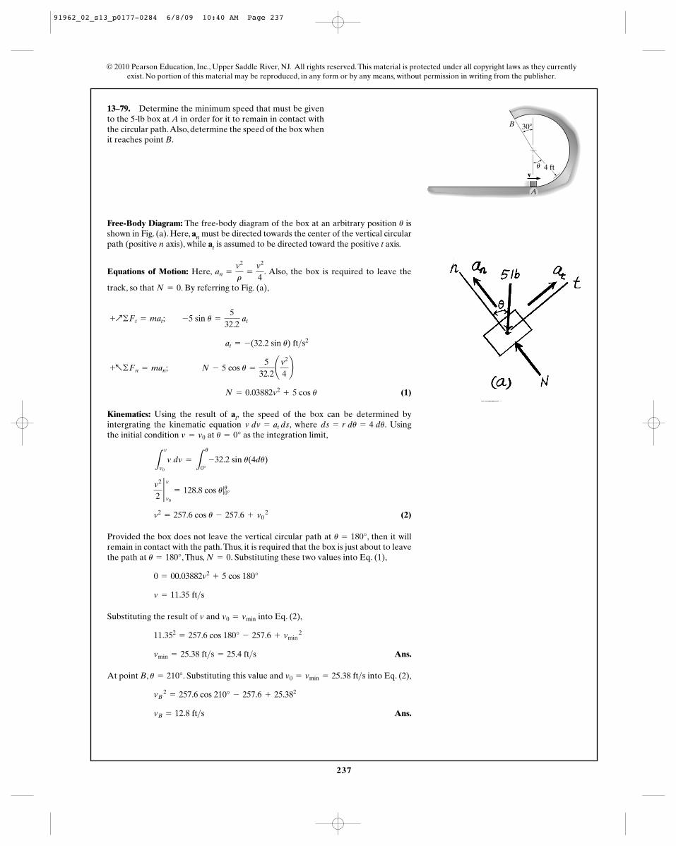
237
13–79. Determine the minimum speed that must be givento the 5-lb box at A in order for it to remain in contact withthe circular path.Also, determine the speed of the box whenit reaches point B.
Free-Body Diagram: The free-body diagram of the box at an arbitrary position isshown in Fig. (a). Here, an must be directed towards the center of the vertical circularpath (positive n axis), while at is assumed to be directed toward the positive t axis.
Equations of Motion: Here, . Also, the box is required to leave the
track, so that . By referring to Fig. (a),
(1)
Kinematics: Using the result of at, the speed of the box can be determined byintergrating the kinematic equation , where . Usingthe initial condition at as the integration limit,
(2)
Provided the box does not leave the vertical circular path at , then it willremain in contact with the path.Thus, it is required that the box is just about to leavethe path at , Thus, . Substituting these two values into Eq. (1),
Substituting the result of and into Eq. (2),
Ans.
At point B, . Substituting this value and into Eq. (2),
Ans.vB = 12.8 ft>s
vB 2
= 257.6 cos 210° - 257.6 + 25.382
v0 = vmin = 25.38 ft>su = 210°
vmin = 25.38 ft>s = 25.4 ft>s
11.352= 257.6 cos 180° - 257.6 + vmin
2
v0 = vminv
v = 11.35 ft>s
0 = 00.03882v2+ 5 cos 180°
N = 0u = 180°
u = 180°
v2= 257.6 cos u - 257.6 + v0
2
v2
22 vv0
= 128.8 cos u|u0°
L
v
v0
v dv =
L
u
0°-32.2 sin u(4du)
u = 0°v = v0
ds = r du = 4 duv dv = at ds
N = 0.03882v2+ 5 cos u
+a©Fn = man; N - 5 cos u =
532.2¢v2
4≤
at = -(32.2 sin u) ft>s2
+Q©Ft = mat; -5 sin u =
532.2
at
N = 0
an =
v2
r=
v2
4
u
© 2010 Pearson Education, Inc., Upper Saddle River, NJ. All rights reserved. This material is protected under all copyright laws as they currentlyexist. No portion of this material may be reproduced, in any form or by any means, without permission in writing from the publisher.
B
4 ftv
A
30�
u
91962_02_s13_p0177-0284 6/8/09 10:40 AM Page 237
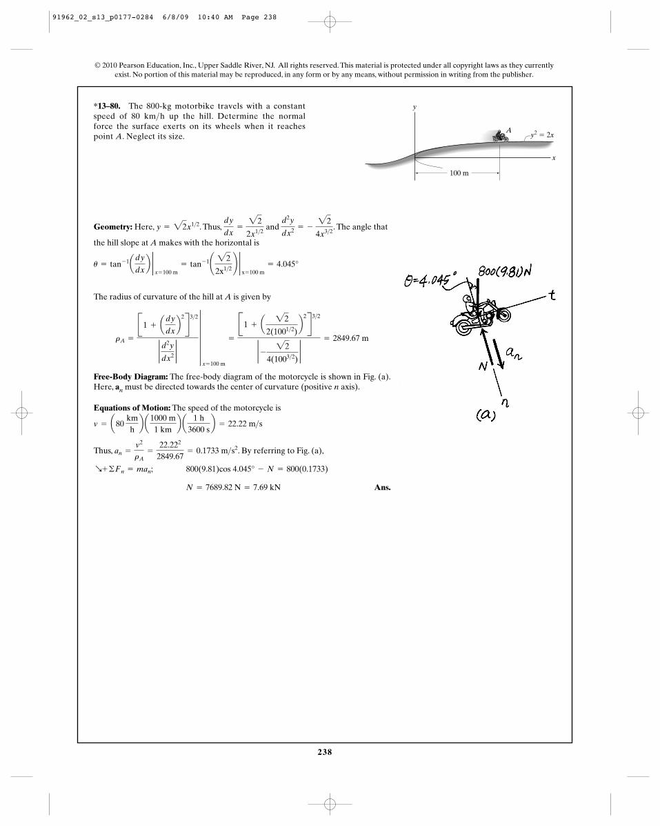
238
*13–80. The 800-kg motorbike travels with a constantspeed of 80 km h up the hill. Determine the normalforce the surface exerts on its wheels when it reachespoint A. Neglect its size.
>
© 2010 Pearson Education, Inc., Upper Saddle River, NJ. All rights reserved. This material is protected under all copyright laws as they currentlyexist. No portion of this material may be reproduced, in any form or by any means, without permission in writing from the publisher.
Geometry: Here, . Thus, and . The angle that
the hill slope at A makes with the horizontal is
The radius of curvature of the hill at A is given by
Free-Body Diagram: The free-body diagram of the motorcycle is shown in Fig. (a).Here, an must be directed towards the center of curvature (positive n axis).
Equations of Motion: The speed of the motorcycle is
Thus, . By referring to Fig. (a),
Ans. N = 7689.82 N = 7.69 kN
R+ ©Fn = man; 800(9.81)cos 4.045° - N = 800(0.1733)
an =
v2
rA=
22.222
2849.67= 0.1733 m>s2
v = a80 kmhb a
1000 m1 km
b a1 h
3600 sb = 22.22 m>s
rA =
B1 + ady
dxb
2R3>2
2 d2y
dx22
5x = 100 m
=
B1 + a22
2(1001>2)b
2R3>2
2 - 22
4(1003>2)2
= 2849.67 m
u = tan- 1ady
dxb 2
x = 100 m= tan- 1¢ 22
2x1>2≤ 2
x = 100 m= 4.045°
d2y
dx2 = - 22
4x3>2
dy
dx=
22
2x1>2y = 22x1>2
y
100 m
A
x
y2 � 2x
91962_02_s13_p0177-0284 6/8/09 10:40 AM Page 238
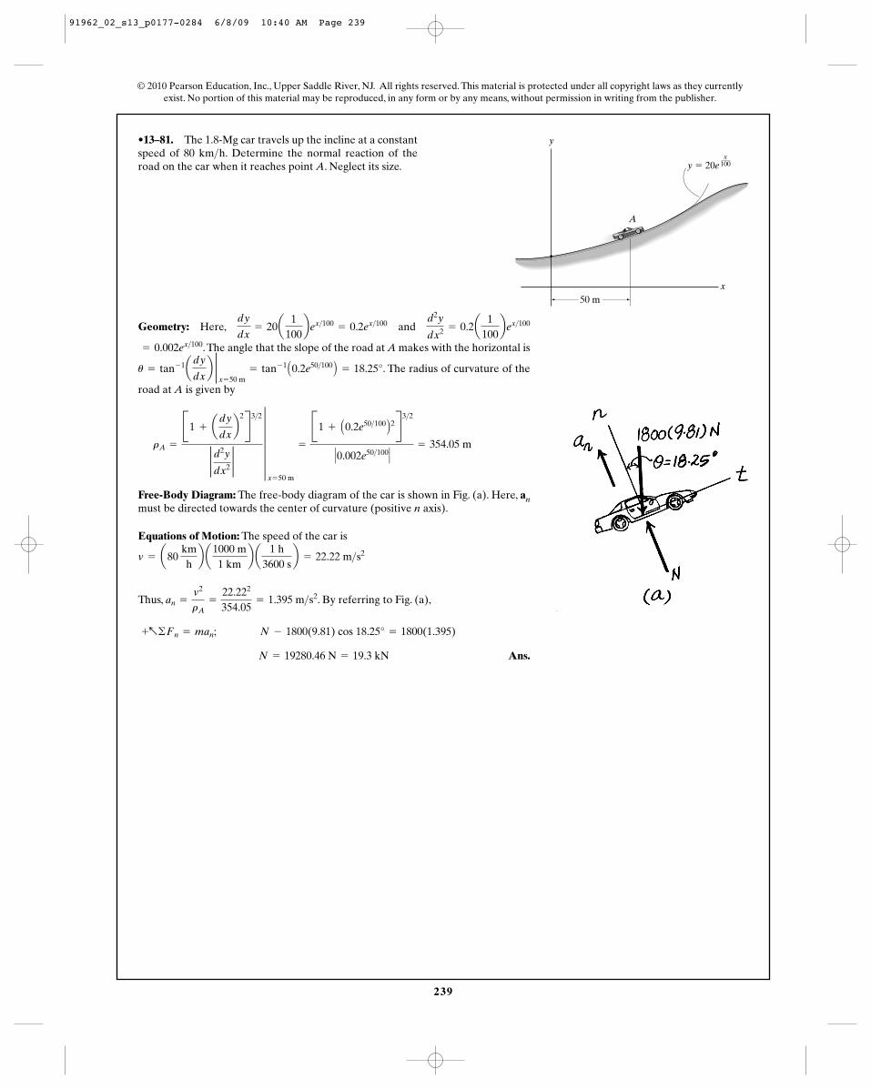
239
•13–81. The 1.8-Mg car travels up the incline at a constantspeed of 80 km h. Determine the normal reaction of theroad on the car when it reaches point A. Neglect its size.
>
Geometry: Here, and
.The angle that the slope of the road at A makes with the horizontal is
. The radius of curvature of the
road at A is given by
Free-Body Diagram: The free-body diagram of the car is shown in Fig. (a). Here, anmust be directed towards the center of curvature (positive n axis).
Equations of Motion: The speed of the car is
Thus, . By referring to Fig. (a),
Ans. N = 19280.46 N = 19.3 kN
+a©Fn = man; N - 1800(9.81) cos 18.25° = 1800(1.395)
an =
v2
rA=
22.222
354.05= 1.395 m>s2
v = a80 kmhb a
1000 m1 km
b a1 h
3600 sb = 22.22 m>s2
rA =
B1 + ady
dxb
2R3>2
2 d2y
dx22
5x = 50 m
=
B1 + A0.2e50>100 B2R3>2
� 0.002e50>100�= 354.05 m
u = tan- 1ady
dxb 2
x = 50 m= tan- 1 A0.2e50>100 B = 18.25°
= 0.002ex>100
d2y
dx2 = 0.2a1
100bex>100dy
dx= 20a
1100bex>100
= 0.2ex>100
© 2010 Pearson Education, Inc., Upper Saddle River, NJ. All rights reserved. This material is protected under all copyright laws as they currentlyexist. No portion of this material may be reproduced, in any form or by any means, without permission in writing from the publisher.
y
x
y � 20e
50 m
x100
A
91962_02_s13_p0177-0284 6/8/09 10:40 AM Page 239
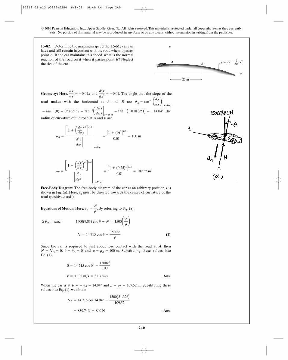
240
13–82. Determine the maximum speed the 1.5-Mg car canhave and still remain in contact with the road when it passespoint A. If the car maintains this speed, what is the normalreaction of the road on it when it passes point B? Neglectthe size of the car.
© 2010 Pearson Education, Inc., Upper Saddle River, NJ. All rights reserved. This material is protected under all copyright laws as they currentlyexist. No portion of this material may be reproduced, in any form or by any means, without permission in writing from the publisher.
Geometry: Here, and . The angle that the slope of thed2y
dx2 = -0.01dx
dy= -0.01x
1200
y
x
25 m
A B y � 25 � x2
road makes with the horizontal at A and B are uA = tan- 1ady
dxb 2
x = 0 m
and . The
radius of curvature of the road at A and B are
Free-Body Diagram: The free-body diagram of the car at an arbitrary position x isshown in Fig. (a). Here, an must be directed towards the center of curvature of theroad (positive n axis).
Equations of Motion: Here, . By referring to Fig. (a),
(1)
Since the car is required to just about lose contact with the road at A, then, and . Substituting these values into
Eq. (1),
Ans.
When the car is at B, and . Substituting thesevalues into Eq. (1), we obtain
Ans. = 839.74N = 840 N
NB = 14 715 cos 14.04° -
1500 A31.322 B
109.52
r = rB = 109.52 mu = uB = 14.04°
v = 31.32 m>s = 31.3 m>s
0 = 14 715 cos 0° -
1500v2
100
r = rA = 100 mu = uA = 0N = NA = 0
N = 14 715 cos u -
1500v2
r
©Fn = man; 1500(9.81) cos u - N = 1500¢v2
r≤
an =
v2
r
rB =
B1 + ady
dxb
2R3>2
2 d2y
dx22
5x = 25 m
=
C1 + (0.25)2 D3>2
0.01= 109.52 m
rA =
B1 + ady
dxb
2R3>2
2 d2y
dx22
5x = 0 m
=
C1 + (0)2 D3>2
0.01= 100 m
uB = tan- 1ady
dxb 2
x = 25 m= tan- 1 A -0.01(25) B = -14.04°= tan- 1(0) = 0°
91962_02_s13_p0177-0284 6/8/09 10:40 AM Page 240
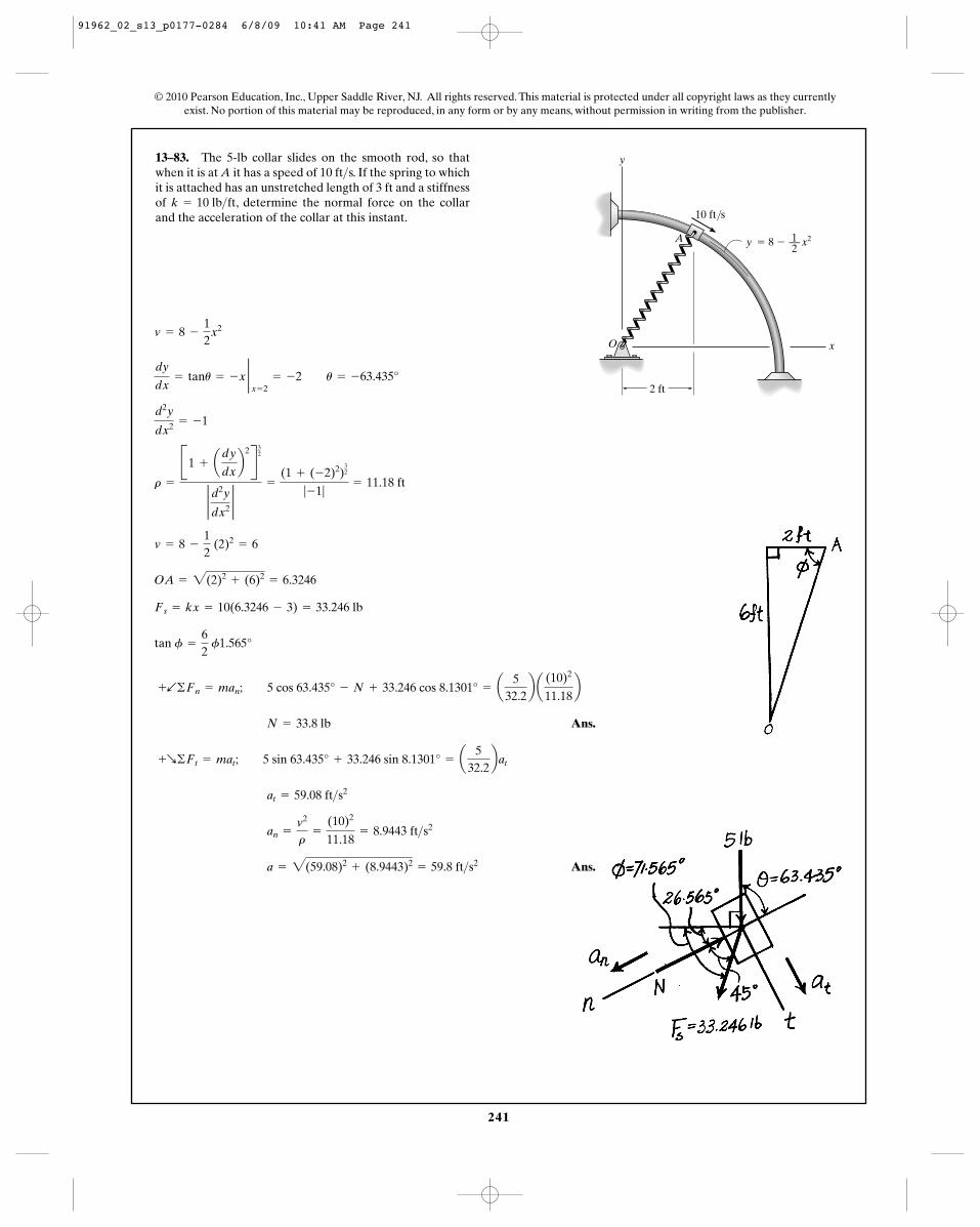
241
13–83. The 5-lb collar slides on the smooth rod, so thatwhen it is at A it has a speed of 10 ft s. If the spring to whichit is attached has an unstretched length of 3 ft and a stiffnessof , determine the normal force on the collarand the acceleration of the collar at this instant.
k = 10 lb>ft
>
© 2010 Pearson Education, Inc., Upper Saddle River, NJ. All rights reserved. This material is protected under all copyright laws as they currentlyexist. No portion of this material may be reproduced, in any form or by any means, without permission in writing from the publisher.
2 ft
10 ft/s
A
O
y
x
1––2
y � 8 � x2
Ans.
Ans. a = 2(59.08)2+ (8.9443)2
= 59.8 ft>s2
an =
v2
r=
(10)2
11.18= 8.9443 ft>s2
at = 59.08 ft>s2
+R©Ft = mat; 5 sin 63.435° + 33.246 sin 8.1301° = a5
32.2bat
N = 33.8 lb
+b©Fn = man; 5 cos 63.435° - N + 33.246 cos 8.1301° = a5
32.2b a
(10)2
11.18b
tan f =
62
f1.565°
Fs = kx = 10(6.3246 - 3) = 33.246 lb
OA = 2(2)2+ (6)2
= 6.3246
v = 8 -
12
(2)2= 6
r =
B1 + ady
dxb
2R32
2 d2y
dx22
=
(1 + (-2)2)32
|-1|= 11.18 ft
d2y
dx2 = -1
dy
dx= tanu = -x 2
x = 2= -2 u = -63.435°
v = 8 -
12
x2
91962_02_s13_p0177-0284 6/8/09 10:41 AM Page 241
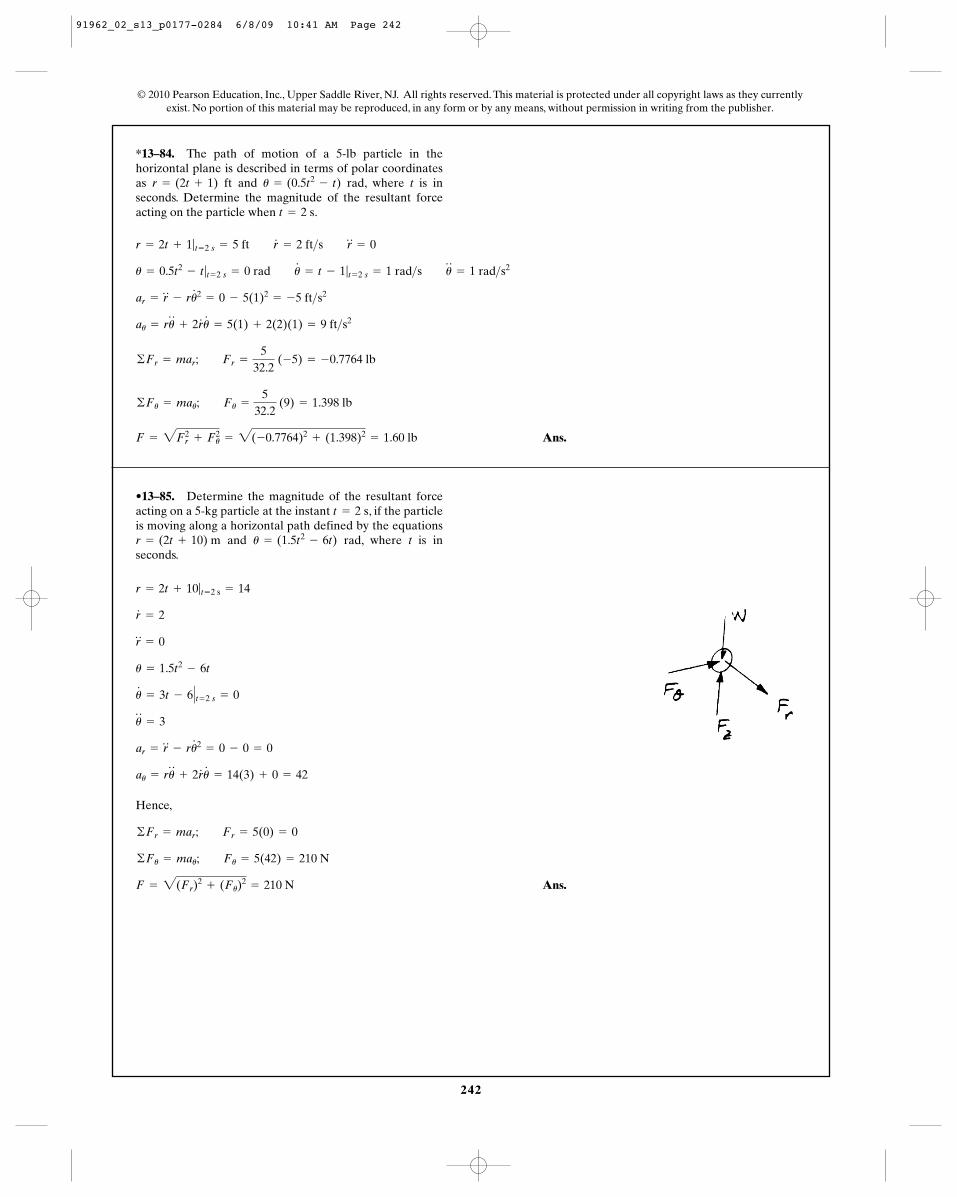
242
*13–84. The path of motion of a 5-lb particle in thehorizontal plane is described in terms of polar coordinatesas and rad, where t is inseconds. Determine the magnitude of the resultant forceacting on the particle when .t = 2 s
u = (0.5t2- t)r = (2t + 1) ft
© 2010 Pearson Education, Inc., Upper Saddle River, NJ. All rights reserved. This material is protected under all copyright laws as they currentlyexist. No portion of this material may be reproduced, in any form or by any means, without permission in writing from the publisher.
Ans.F = 2Fr2
+ F2u = 2(-0.7764)2
+ (1.398)2= 1.60 lb
©Fu = mau; Fu =
532.2
(9) = 1.398 lb
©Fr = mar; Fr =
532.2
(-5) = -0.7764 lb
au = ru$
+ 2r#
u#
= 5(1) + 2(2)(1) = 9 ft>s2
ar = r$
- ru#2
= 0 - 5(1)2= -5 ft>s2
u = 0.5t2- t|t = 2 s = 0 rad u
#
= t - 1|t = 2 s = 1 rad>s u$
= 1 rad>s2
r = 2t + 1|t = 2 s = 5 ft r#
= 2 ft>s r$
= 0
•13–85. Determine the magnitude of the resultant forceacting on a 5-kg particle at the instant , if the particleis moving along a horizontal path defined by the equations
and rad, where t is inseconds.
u = (1.5t2- 6t)r = (2t + 10) m
t = 2 s
Hence,
Ans.F = 2(Fr)2
+ (Fu)2
= 210 N
©Fu = mau; Fu = 5(42) = 210 N
©Fr = mar; Fr = 5(0) = 0
au = ru$
+ 2r#
u#
= 14(3) + 0 = 42
ar = r$
- ru#2
= 0 - 0 = 0
u$
= 3
u#
= 3t - 6� t = 2 s = 0
u = 1.5t2- 6t
r$
= 0
r#
= 2
r = 2t + 10|t = 2 s = 14
91962_02_s13_p0177-0284 6/8/09 10:41 AM Page 242
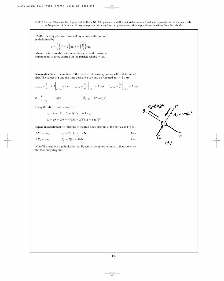
243
© 2010 Pearson Education, Inc., Upper Saddle River, NJ. All rights reserved. This material is protected under all copyright laws as they currentlyexist. No portion of this material may be reproduced, in any form or by any means, without permission in writing from the publisher.
13–86. A 2-kg particle travels along a horizontal smoothpath defined by
,
where t is in seconds. Determine the radial and transversecomponents of force exerted on the particle when .t = 2 s
r = ¢14
t3+ 2≤ m, u = ¢ t2
4≤ rad
Kinematics: Since the motion of the particle is known, ar and will be determinedfirst. The values of r and the time derivative of r and evaluated at aret = 2 su
au
r|t = 2 s =
14
t3+ 2 2
t = 2 s= 4 m r
#
|t = 2 s =
34
t2 2t = 2 s
= 3 m>s r$
|t = 2 s =
32
t 2t = 2 s
= 3 m>s2
Using the above time derivative,
Equations of Motion: By referring to the free-body diagram of the particle in Fig. (a),
Ans.
Ans.
Note: The negative sign indicates that Fr acts in the opposite sense to that shown onthe free-body diagram.
©Fu = mau; Fu = 2(8) = 16 N
©Fr = mar; Fr = 2(-1) = -2 N
au = ru$
+ 2r#
u#
= 4(0.5) + 2(3)(1) = 8 m>s2
ar = r$
- ru#2
= 3 - 4(12) = - 1 m>s2
u#
=
t
22t = 2 s
= 1 rad>s u$
� t = 2 s = 0.5 rad>s2
91962_02_s13_p0177-0284 6/8/09 10:41 AM Page 243
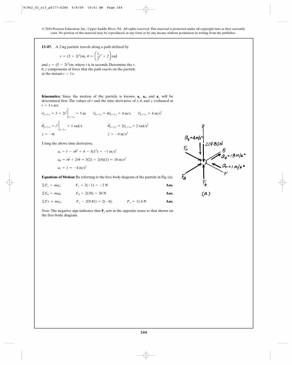
244
© 2010 Pearson Education, Inc., Upper Saddle River, NJ. All rights reserved. This material is protected under all copyright laws as they currentlyexist. No portion of this material may be reproduced, in any form or by any means, without permission in writing from the publisher.
13–87. A 2-kg particle travels along a path defined by
and , where t is in seconds. Determine the r,, z components of force that the path exerts on the particle
at the instant .t = 1 su
z = (5 - 2t2) m
r = (3 + 2t2) m, u = ¢13
t3+ 2≤ rad
Kinematics: Since the motion of the particle is known, ar, , and az will bedetermined first. The values of r and the time derivative of r, , and z evaluated at
are
Using the above time derivative,
Equations of Motion: By referring to the free-body diagram of the particle in Fig. (a),
Ans.
Ans.
Ans.
Note: The negative sign indicates that Fr acts in the opposite sense to that shown onthe free-body diagram.
©Fz = maz; Fz - 2(9.81) = 2(-4); Fz = 11.6 N
©Fu = mau; Fu = 2(18) = 36 N
©Fr = mar; Fr = 2(-1) = -2 N
az = z$
= -4 m>s2
au = ru$
+ 2r#
u#
= 5(2) + 2(4)(1) = 18 m>s2
ar = r$
- ru#2
= 4 - 5(12) = -1 m>s2
z#
= -4t z$
= -4 m>s2
u#
� t = 1 s = t2 2t = 1 s
= 1 rad>s u$
� t = 1 s = 2t|t = 1 s = 2 rad>s2
r|t = 1 s = 3 + 2t2 2t = 1 s
= 5 m r#
|t = 1 s = 4t|t = 1 s = 4 m>s r$
|t = 1 s = 4 m>s2
t = 1 su
au
91962_02_s13_p0177-0284 6/8/09 10:41 AM Page 244
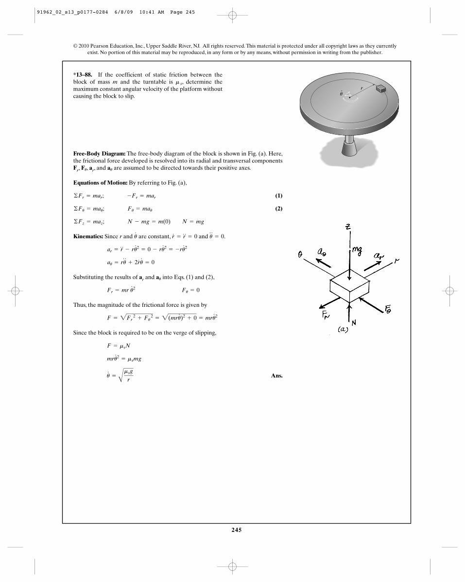
245
© 2010 Pearson Education, Inc., Upper Saddle River, NJ. All rights reserved. This material is protected under all copyright laws as they currentlyexist. No portion of this material may be reproduced, in any form or by any means, without permission in writing from the publisher.
*13–88. If the coefficient of static friction between theblock of mass m and the turntable is , determine themaximum constant angular velocity of the platform withoutcausing the block to slip.
m s
Free-Body Diagram: The free-body diagram of the block is shown in Fig. (a). Here,the frictional force developed is resolved into its radial and transversal componentsFr, , ar, and are assumed to be directed towards their positive axes.
Equations of Motion: By referring to Fig. (a),
(1)
(2)
Kinematics: Since r and are constant, and .
Substituting the results of ar and into Eqs. (1) and (2),
Thus, the magnitude of the frictional force is given by
Since the block is required to be on the verge of slipping,
Ans.u#
=
A
msg
r
mru#2
= msmg
F = msN
F = 2Fr 2
+ Fu 2
= 2(mru#
)2+ 0 = mru
#2
Fr = mr u#2 Fu = 0
au
au = ru$
+ 2r#
u#
= 0
ar = r$
- ru#2
= 0 - ru#2
= -ru#2
u$
= 0r#
= r$
= 0u#
©Fz = maz; N - mg = m(0) N = mg
©Fu = mau; Fu = mau
©Fr = mar; -Fr = mar
auFu
ru
91962_02_s13_p0177-0284 6/8/09 10:41 AM Page 245
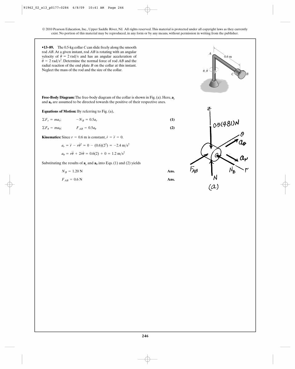
246
© 2010 Pearson Education, Inc., Upper Saddle River, NJ. All rights reserved. This material is protected under all copyright laws as they currentlyexist. No portion of this material may be reproduced, in any form or by any means, without permission in writing from the publisher.
•13–89. The 0.5-kg collar C can slide freely along the smoothrod AB.At a given instant, rod AB is rotating with an angularvelocity of and has an angular acceleration of
. Determine the normal force of rod AB and theradial reaction of the end plate B on the collar at this instant.Neglect the mass of the rod and the size of the collar.
u$
= 2 rad>s2u#
= 2 rad>s
Free-Body Diagram: The free-body diagram of the collar is shown in Fig. (a). Here, arand are assumed to be directed towards the positive of their respective axes.
Equations of Motion: By referring to Fig. (a),
(1)
(2)
Kinematics: Since is constant, .
Substituting the results of ar and into Eqs. (1) and (2) yields
Ans.
Ans.FAB = 0.6 N
NB = 1.20 N
au
au = ru$
+ 2r#
u#
= 0.6(2) + 0 = 1.2 m>s2
ar = r$
- ru#2
= 0 - (0.6)(22) = -2.4 m>s2
r#
= r$
= 0r = 0.6 m
©Fu = mau; FAB = 0.5au
©Fr = mar; -NB = 0.5ar
au
A
C B
0.6 m
u, u
91962_02_s13_p0177-0284 6/8/09 10:41 AM Page 246
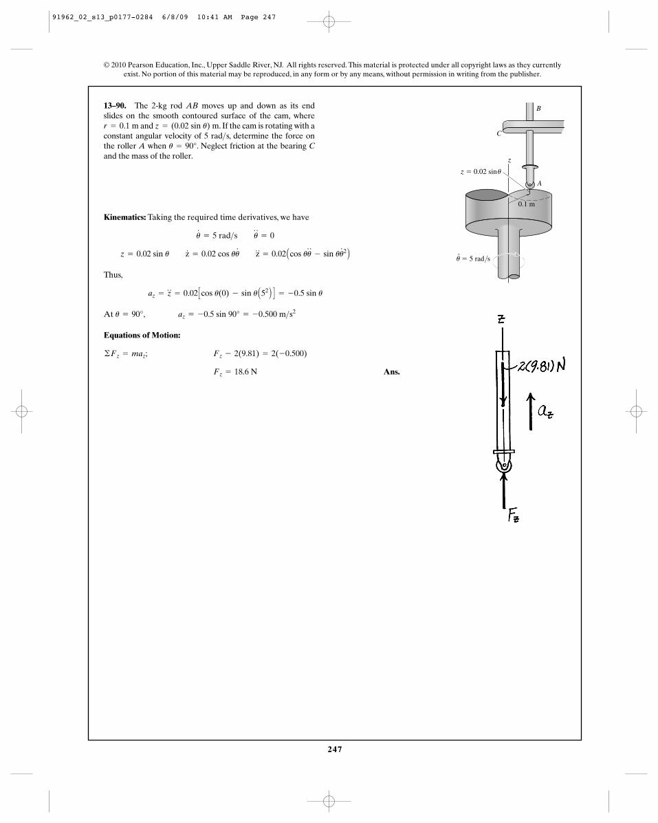
247
© 2010 Pearson Education, Inc., Upper Saddle River, NJ. All rights reserved. This material is protected under all copyright laws as they currentlyexist. No portion of this material may be reproduced, in any form or by any means, without permission in writing from the publisher.
13–90. The 2-kg rod AB moves up and down as its endslides on the smooth contoured surface of the cam, where
and . If the cam is rotating with aconstant angular velocity of 5 rad s, determine the force onthe roller A when . Neglect friction at the bearing Cand the mass of the roller.
u = 90°>
z = (0.02 sin u) mr = 0.1 m
Kinematics: Taking the required time derivatives, we have
Thus,
At
Equations of Motion:
Ans.Fz = 18.6 N
©Fz = maz; Fz - 2(9.81) = 2(-0.500)
u = 90°, az = -0.5 sin 90° = -0.500 m>s2
az = z$
= 0.02 Ccos u(0) - sin u A52 B D = -0.5 sin u
z = 0.02 sin u z#
= 0.02 cos uu# z
$
= 0.02 Acos uu$
- sin uu#2 B
u#
= 5 rad>s u$
= 0
z
z � 0.02 sin
0.1 m
� 5 rad/s
A
u
u
C
B
91962_02_s13_p0177-0284 6/8/09 10:41 AM Page 247
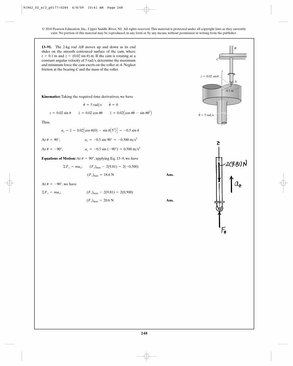
248
© 2010 Pearson Education, Inc., Upper Saddle River, NJ. All rights reserved. This material is protected under all copyright laws as they currentlyexist. No portion of this material may be reproduced, in any form or by any means, without permission in writing from the publisher.
13–91. The 2-kg rod AB moves up and down as its endslides on the smooth contoured surface of the cam, where
and . If the cam is rotating at aconstant angular velocity of 5 rad s, determine the maximumand minimum force the cam exerts on the roller at A. Neglectfriction at the bearing C and the mass of the roller.
>z = (0.02 sin u) mr = 0.1 m
Kinematics: Taking the required time derivatives, we have
Thus,
At
At
Equations of Motion: At , applying Eq. 13–9, we have
Ans.
At , we have
Ans.(Fz)max = 20.6 N
©Fz = maz; (Fz)max - 2(9.81) = 2(0.500)
u = -90°
(Fz)min = 18.6 N
©Fz = maz; (Fz)min - 2(9.81) = 2(-0.500)
u = 90°
u = -90°, az = -0.5 sin (-90°) = 0.500 m>s2
u = 90°, az = -0.5 sin 90° = -0.500 m>s2
az = z$
= 0.02 Ccos u(0) - sin u A52 B D = -0.5 sin u
z = 0.02 sin u z#
= 0.02 cos uu# z
$
= 0.02 Acos uu$
- sin uu#2 B
u#
= 5 rad>s u$
= 0
z
z � 0.02 sin
0.1 m
� 5 rad/s
A
u
u
C
B
91962_02_s13_p0177-0284 6/8/09 10:41 AM Page 248
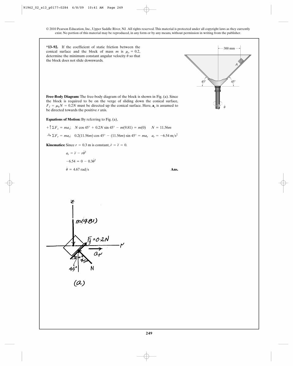
249
© 2010 Pearson Education, Inc., Upper Saddle River, NJ. All rights reserved. This material is protected under all copyright laws as they currentlyexist. No portion of this material may be reproduced, in any form or by any means, without permission in writing from the publisher.
*13–92. If the coefficient of static friction between theconical surface and the block of mass m is ,determine the minimum constant angular velocity so thatthe block does not slide downwards.
u#ms = 0.2
Free-Body Diagram: The free-body diagram of the block is shown in Fig. (a). Sincethe block is required to be on the verge of sliding down the conical surface,
must be directed up the conical surface. Here, ar is assumed tobe directed towards the positive r axis.
Equations of Motion: By referring to Fig. (a),
Kinematics: Since is constant,
Ans.u#
= 4.67 rad>s
-6.54 = 0 - 0.3u#2
ar = r$
- ru#2
r#
= r$
= 0.r = 0.3 m
:+ ©Fr = mar; 0.2(11.56m) cos 45° - (11.56m) sin 45° = mar ar = -6.54 m>s2
+ c ©Fz = maz; N cos 45° + 0.2N sin 45° - m(9.81) = m(0) N = 11.56m
Ff = mkN = 0.2N
A
300 mm
45�45�
u
91962_02_s13_p0177-0284 6/8/09 10:41 AM Page 249
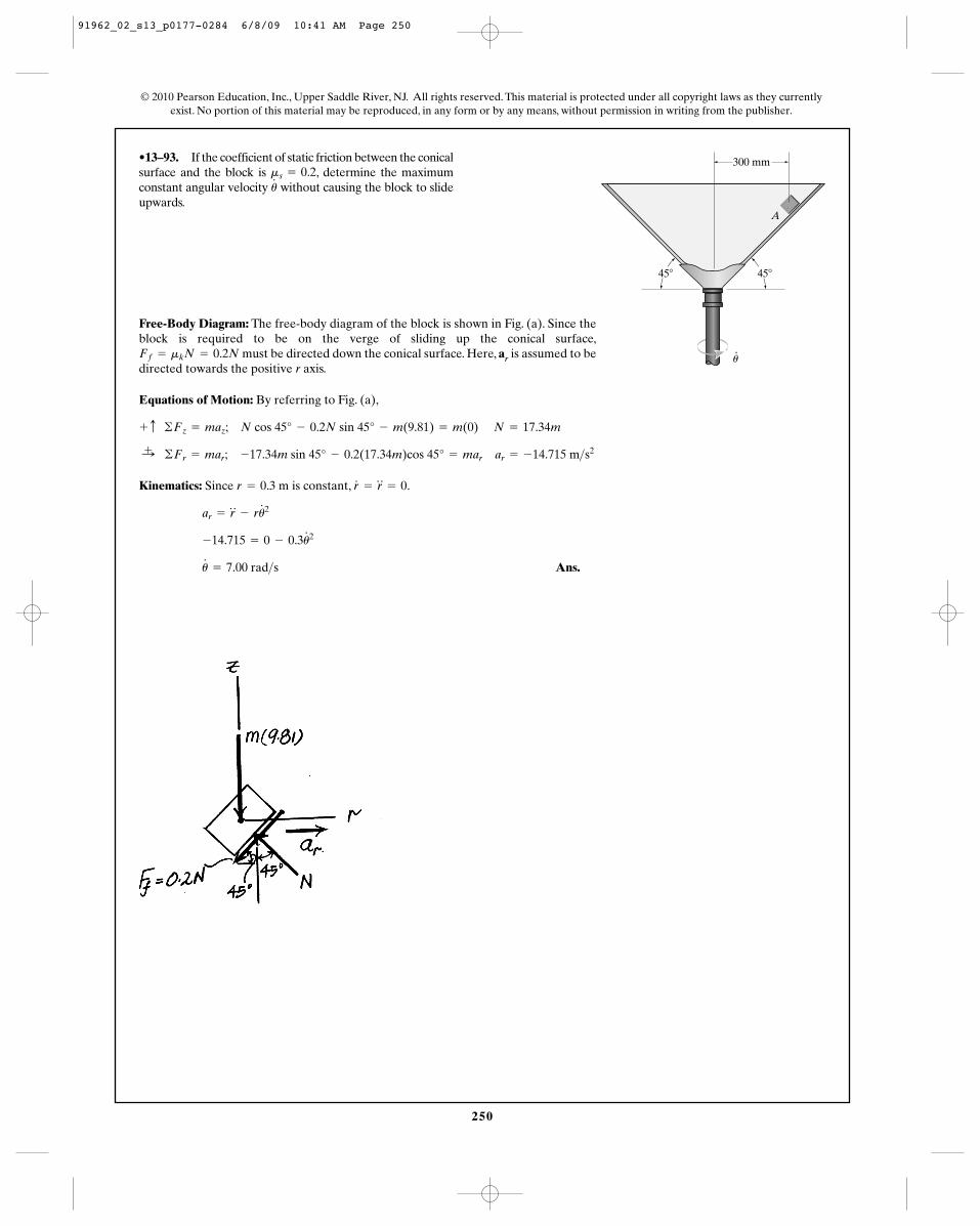
250
© 2010 Pearson Education, Inc., Upper Saddle River, NJ. All rights reserved. This material is protected under all copyright laws as they currentlyexist. No portion of this material may be reproduced, in any form or by any means, without permission in writing from the publisher.
•13–93. If the coefficient of static friction between the conicalsurface and the block is , determine the maximumconstant angular velocity without causing the block to slideupwards.
u#ms = 0.2
Free-Body Diagram: The free-body diagram of the block is shown in Fig. (a). Since theblock is required to be on the verge of sliding up the conical surface,
must be directed down the conical surface. Here, ar is assumed to bedirected towards the positive r axis.
Equations of Motion: By referring to Fig. (a),
Kinematics: Since is constant, .
Ans.u#
= 7.00 rad>s
-14.715 = 0 - 0.3u#2
ar = r$
- ru#2
r#
= r$
= 0r = 0.3 m
:+ ©Fr = mar; -17.34m sin 45° - 0.2(17.34m)cos 45° = mar ar = -14.715 m>s2
+ c ©Fz = maz; N cos 45° - 0.2N sin 45° - m(9.81) = m(0) N = 17.34m
Ff = mkN = 0.2N
A
300 mm
45�45�
u
91962_02_s13_p0177-0284 6/8/09 10:41 AM Page 250
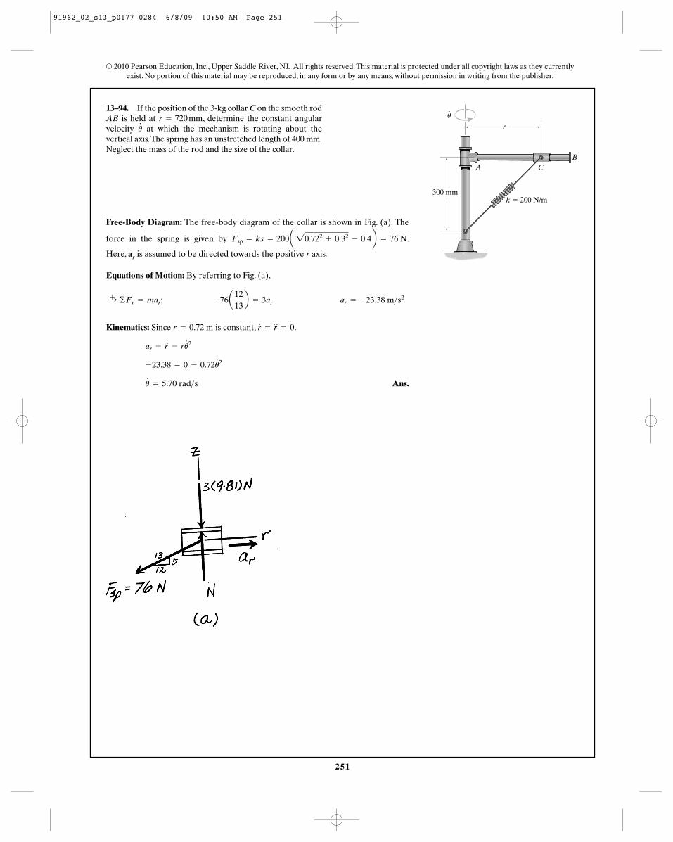
251
© 2010 Pearson Education, Inc., Upper Saddle River, NJ. All rights reserved. This material is protected under all copyright laws as they currentlyexist. No portion of this material may be reproduced, in any form or by any means, without permission in writing from the publisher.
13–94. If the position of the 3-kg collar C on the smooth rodAB is held at , determine the constant angularvelocity at which the mechanism is rotating about thevertical axis.The spring has an unstretched length of 400 mm.Neglect the mass of the rod and the size of the collar.
u#
r = 720 mm
Free-Body Diagram: The free-body diagram of the collar is shown in Fig. (a). The
k � 200 N/m300 mm
r
AB
C
u
force in the spring is given by .Fsp = ks = 200a20.722+ 0.32
- 0.4b = 76 N
Here, ar is assumed to be directed towards the positive r axis.
Equations of Motion: By referring to Fig. (a),
Kinematics: Since is constant, .
Ans.u#
= 5.70 rad>s
-23.38 = 0 - 0.72u#2
ar = r$
- ru#2
r#
= r$
= 0r = 0.72 m
:+ ©Fr = mar; -76a1213b = 3ar ar = -23.38 m>s2
91962_02_s13_p0177-0284 6/8/09 10:50 AM Page 251
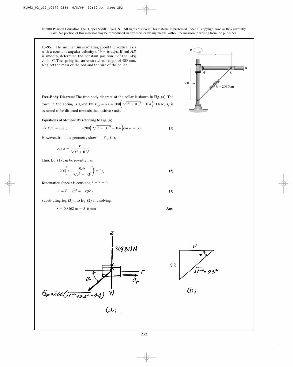
252
© 2010 Pearson Education, Inc., Upper Saddle River, NJ. All rights reserved. This material is protected under all copyright laws as they currentlyexist. No portion of this material may be reproduced, in any form or by any means, without permission in writing from the publisher.
13–95. The mechanism is rotating about the vertical axiswith a constant angular velocity of . If rod ABis smooth, determine the constant position r of the 3-kgcollar C. The spring has an unstretched length of 400 mm.Neglect the mass of the rod and the size of the collar.
u#
= 6 rad>s
k � 200 N/m300 mm
r
AB
C
u
force in the spring is given by . Here, ar isFsp = ks = 200a2r2+ 0.32
- 0.4b
Free-Body Diagram: The free-body diagram of the collar is shown in Fig. (a). The
assumed to be directed towards the positive r axis.
Equations of Motion: By referring to Fig. (a),
(1)
However, from the geometry shown in Fig. (b),
Thus, Eq. (1) can be rewritten as
(2)
Kinematics: Since r is constant, .
(3)
Substituting Eq. (3) into Eq. (2) and solving,
Ans.r = 0.8162 m = 816 mm
ar = r$
- ru#2
= -r(62)
r#
= r$
= 0
-200¢r—0.4r
2r2+ 0.32
≤ = 3ar
cos a =
r
2r2+ 0.32
:+ ©Fr = ma r; -200a2r2+ 0.32
- 0.4bcos a = 3ar
91962_02_s13_p0177-0284 6/8/09 10:50 AM Page 252
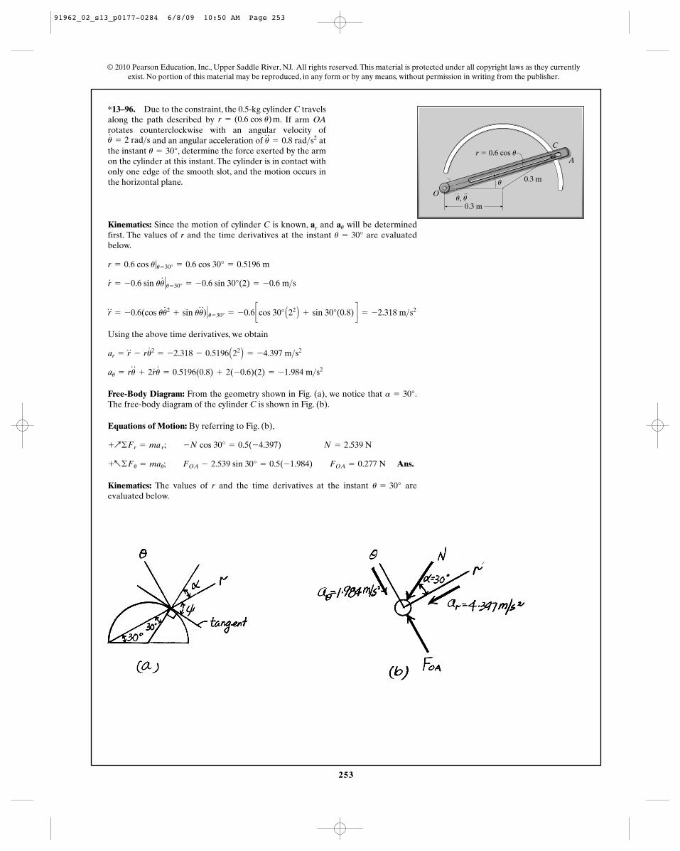
253
© 2010 Pearson Education, Inc., Upper Saddle River, NJ. All rights reserved. This material is protected under all copyright laws as they currentlyexist. No portion of this material may be reproduced, in any form or by any means, without permission in writing from the publisher.
*13–96. Due to the constraint, the 0.5-kg cylinder C travelsalong the path described by . If arm OArotates counterclockwise with an angular velocity of
and an angular acceleration of atthe instant , determine the force exerted by the armon the cylinder at this instant. The cylinder is in contact withonly one edge of the smooth slot, and the motion occurs inthe horizontal plane.
u = 30°u$
= 0.8 rad>s2u#
= 2 rad>s
r = (0.6 cos u) m
Kinematics: Since the motion of cylinder C is known, ar and will be determinedfirst. The values of r and the time derivatives at the instant are evaluatedbelow.
Using the above time derivatives, we obtain
Free-Body Diagram: From the geometry shown in Fig. (a), we notice that .The free-body diagram of the cylinder C is shown in Fig. (b).
Equations of Motion: By referring to Fig. (b),
Ans.
Kinematics: The values of r and the time derivatives at the instant areevaluated below.
u = 30°
+a©Fu = mau; FOA - 2.539 sin 30° = 0.5(-1.984) FOA = 0.277 N
+Q©Fr = ma r; -N cos 30° = 0.5(-4.397) N = 2.539 N
a = 30°
au = ru$
+ 2r#
u#
= 0.5196(0.8) + 2(-0.6)(2) = -1.984 m>s2
ar = r$
- ru#2
= -2.318 - 0.5196 A22 B = -4.397 m>s2
r$
= -0.6(cos uu#2
+ sin uu$
)� u= 30° = -0.6 ccos 30° A22 B + sin 30°(0.8) d = -2.318 m>s2
r#
= -0.6 sin uu#
� u= 30° = -0.6 sin 30°(2) = -0.6 m>s
r = 0.6 cos u|u= 30° = 0.6 cos 30° = 0.5196 m
u = 30°au
O
A
Cr � 0.6 cos u
0.3 m
0.3 mu
u, u
91962_02_s13_p0177-0284 6/8/09 10:50 AM Page 253
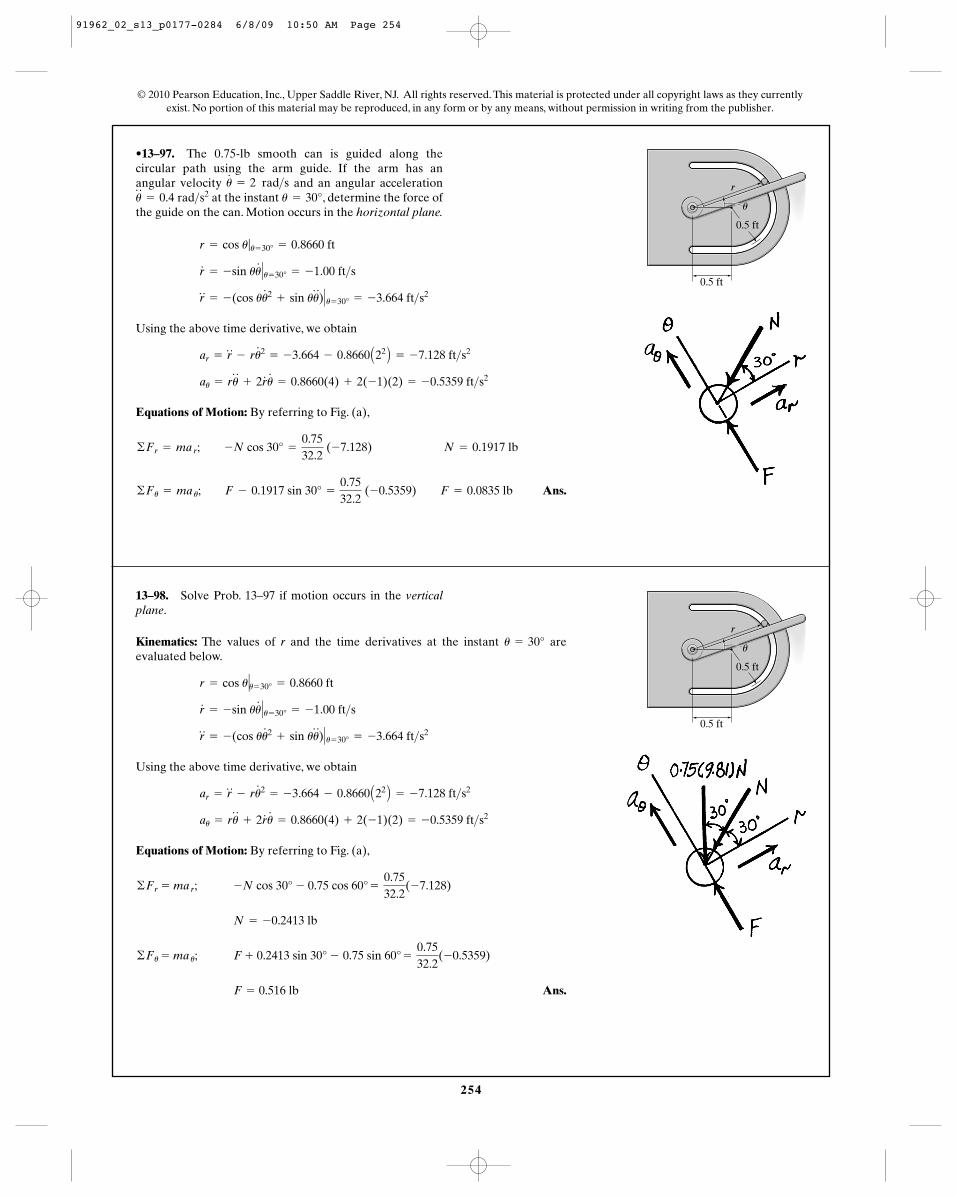
254
© 2010 Pearson Education, Inc., Upper Saddle River, NJ. All rights reserved. This material is protected under all copyright laws as they currentlyexist. No portion of this material may be reproduced, in any form or by any means, without permission in writing from the publisher.
•13–97. The 0.75-lb smooth can is guided along thecircular path using the arm guide. If the arm has anangular velocity and an angular acceleration
at the instant , determine the force ofthe guide on the can. Motion occurs in the horizontal plane.
u = 30°u$
= 0.4 rad>s2u#
= 2 rad>s
Using the above time derivative, we obtain
Equations of Motion: By referring to Fig. (a),
Ans.©Fu = ma u; F - 0.1917 sin 30° =
0.7532.2
(-0.5359) F = 0.0835 lb
©Fr = ma r; -N cos 30° =
0.7532.2
(-7.128) N = 0.1917 lb
au = ru$
+ 2r#
u#
= 0.8660(4) + 2(-1)(2) = -0.5359 ft>s2
ar = r$
- ru#2
= -3.664 - 0.8660 A22 B = -7.128 ft>s2
r$
= -(cos uu#2
+ sin uu$
)� u= 30° = -3.664 ft>s2
r#
= -sin uu#
� u= 30° = -1.00 ft>s
r = cos u|u= 30° = 0.8660 ft
0.5 ft
u
r
0.5 ft
13–98. Solve Prob. 13–97 if motion occurs in the verticalplane.
Kinematics: The values of r and the time derivatives at the instant areevaluated below.
Using the above time derivative, we obtain
Equations of Motion: By referring to Fig. (a),
Ans.F = 0.516 lb
©Fu = ma u; F + 0.2413 sin 30° - 0.75 sin 60° =
0.7532.2
(-0.5359)
N = -0.2413 lb
©Fr = ma r; -N cos 30° - 0.75 cos 60° =
0.7532.2
(-7.128)
au = ru$
+ 2r#
u#
= 0.8660(4) + 2(-1)(2) = -0.5359 ft>s2
ar = r$
- ru#2
= -3.664 - 0.8660 A22 B = -7.128 ft>s2
r$
= -(cos uu#2
+ sin uu$
)� u= 30° = -3.664 ft>s2
r#
= -sin uu#
� u= 30° = -1.00 ft>s
r = cos u�u= 30° = 0.8660 ft
u = 30°
0.5 ft
u
r
0.5 ft
91962_02_s13_p0177-0284 6/8/09 10:50 AM Page 254
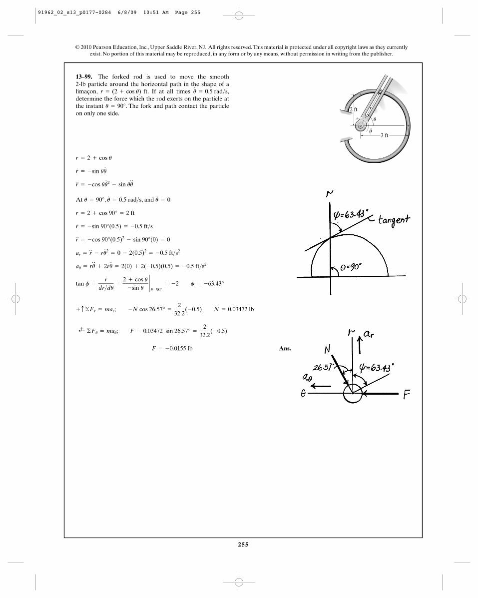
255
13–99. The forked rod is used to move the smooth 2-lb particle around the horizontal path in the shape of alimaçon, . If at all times ,determine the force which the rod exerts on the particle atthe instant . The fork and path contact the particleon only one side.
u = 90°
u#
= 0.5 rad>sr = (2 + cos u) ft
At , , and
Ans. F = -0.0155 lb
;+ ©Fu = mau; F - 0.03472 sin 26.57° =
232.2
(-0.5)
+ c ©Fr = mar; -N cos 26.57° =
232.2
(-0.5) N = 0.03472 lb
tan c =
r
dr>du=
2 + cos u-sin u
2u= 90°
= -2 c = -63.43°
au = ru$
+ 2r#
u#
= 2(0) + 2(-0.5)(0.5) = -0.5 ft>s2
ar = r$
- ru#2
= 0 - 2(0.5)2= -0.5 ft>s2
r$
= -cos 90°(0.5)2- sin 90°(0) = 0
r#
= -sin 90°(0.5) = -0.5 ft>s
r = 2 + cos 90° = 2 ft
u$
= 0u#
= 0.5 rad>su = 90°
r$
= -cos uu#2
- sin uu$
r#
= -sin uu#
r = 2 + cos u
© 2010 Pearson Education, Inc., Upper Saddle River, NJ. All rights reserved. This material is protected under all copyright laws as they currentlyexist. No portion of this material may be reproduced, in any form or by any means, without permission in writing from the publisher.
3 ft
r2 ft
·
u
u
91962_02_s13_p0177-0284 6/8/09 10:51 AM Page 255
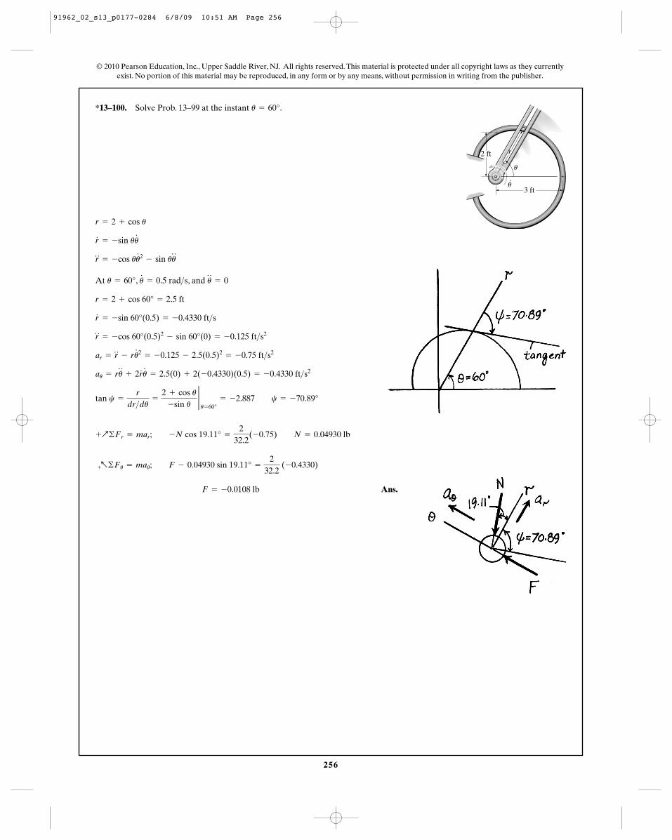
256
*13–100. Solve Prob. 13–99 at the instant .u = 60°
© 2010 Pearson Education, Inc., Upper Saddle River, NJ. All rights reserved. This material is protected under all copyright laws as they currentlyexist. No portion of this material may be reproduced, in any form or by any means, without permission in writing from the publisher.
3 ft
r2 ft
·
u
u
At , , and
Ans. F = -0.0108 lb
+a©Fu = mau; F - 0.04930 sin 19.11° =
232.2
(-0.4330)
+Q©Fr = mar; -N cos 19.11° =
232.2
(-0.75) N = 0.04930 lb
tan c =
r
dr>du=
2 + cos u-sin u
2u= 60°
= -2.887 c = -70.89°
au = ru$
+ 2r#
u#
= 2.5(0) + 2(-0.4330)(0.5) = -0.4330 ft>s2
ar = r$
- ru#2
= -0.125 - 2.5(0.5)2= -0.75 ft>s2
r$
= -cos 60°(0.5)2- sin 60°(0) = -0.125 ft>s2
r#
= -sin 60°(0.5) = -0.4330 ft>s
r = 2 + cos 60° = 2.5 ft
u$
= 0u#
= 0.5 rad>su = 60°
r$
= -cos uu#2
- sin uu$
r#
= -sin uu#
r = 2 + cos u
91962_02_s13_p0177-0284 6/8/09 10:51 AM Page 256
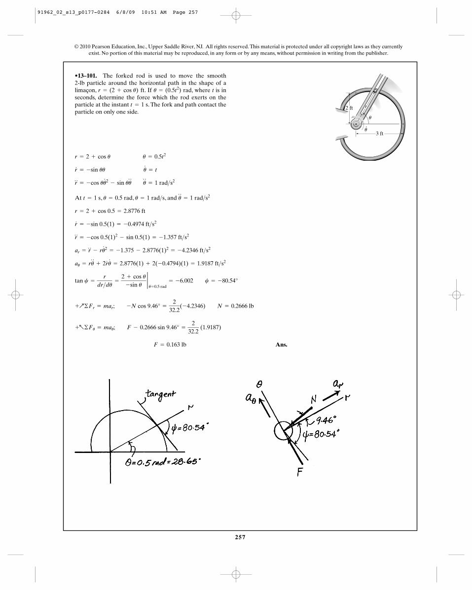
257
•13–101. The forked rod is used to move the smooth 2-lb particle around the horizontal path in the shape of alimaçon, . If rad, where t is inseconds, determine the force which the rod exerts on theparticle at the instant . The fork and path contact theparticle on only one side.
t = 1 s
u = (0.5t2)r = (2 + cos u) ft
At , , , and
Ans. F = 0.163 lb
+a©Fu = mau; F - 0.2666 sin 9.46° =
232.2
(1.9187)
+Q©Fr = mar; -N cos 9.46° =
232.2
(-4.2346) N = 0.2666 lb
tan c =
r
dr>du=
2 + cos u-sin u
2u= 0.5 rad
= -6.002 c = -80.54°
au = ru$
+ 2r#
u#
= 2.8776(1) + 2(-0.4794)(1) = 1.9187 ft>s2
ar = r$
- ru#2
= -1.375 - 2.8776(1)2= -4.2346 ft>s2
r$
= -cos 0.5(1)2- sin 0.5(1) = -1.357 ft>s2
r#
= -sin 0.5(1) = -0.4974 ft>s2
r = 2 + cos 0.5 = 2.8776 ft
u$
= 1 rad>s2u = 1 rad>su = 0.5 radt = 1 s
r$
= -cos uu#2
- sin uu$ u
$
= 1 rad>s2
r#
= -sin uu u#
= t
r = 2 + cos u u = 0.5t2
© 2010 Pearson Education, Inc., Upper Saddle River, NJ. All rights reserved. This material is protected under all copyright laws as they currentlyexist. No portion of this material may be reproduced, in any form or by any means, without permission in writing from the publisher.
3 ft
r2 ft
·
u
u
91962_02_s13_p0177-0284 6/8/09 10:51 AM Page 257
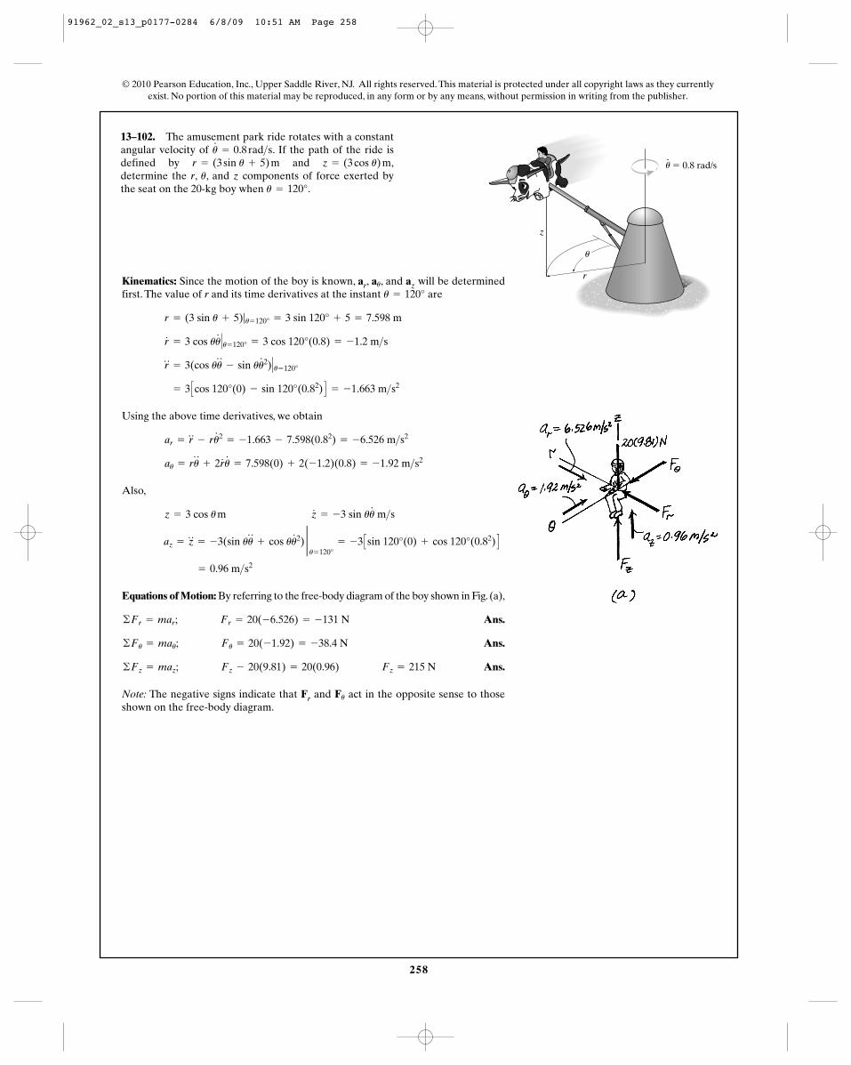
258
13–102. The amusement park ride rotates with a constantangular velocity of . If the path of the ride isdefined by and ,determine the r, , and z components of force exerted bythe seat on the 20-kg boy when .u = 120°
u
z = (3 cos u) mr = (3 sin u + 5) mu#
= 0.8 rad>s
© 2010 Pearson Education, Inc., Upper Saddle River, NJ. All rights reserved. This material is protected under all copyright laws as they currentlyexist. No portion of this material may be reproduced, in any form or by any means, without permission in writing from the publisher.
r
z
� 0.8 rad/s
u
u
Kinematics: Since the motion of the boy is known, ar, , and az will be determinedfirst. The value of r and its time derivatives at the instant are
Using the above time derivatives, we obtain
Also,
Equations of Motion: By referring to the free-body diagram of the boy shown in Fig. (a),
Ans.
Ans.
Ans.
Note: The negative signs indicate that Fr and act in the opposite sense to thoseshown on the free-body diagram.
Fu
©Fz = maz; Fz - 20(9.81) = 20(0.96) Fz = 215 N
©Fu = mau; Fu = 20(-1.92) = -38.4 N
©Fr = mar; Fr = 20(-6.526) = -131 N
= 0.96 m>s2
az = z$
= -3(sin uu$
+ cos uu#2) 2u= 120°
= -3 Csin 120°(0) + cos 120°(0.82) D
z = 3 cos u m z#
= -3 sin uu#
m>s
au = ru$
+ 2r#
u#
= 7.598(0) + 2(-1.2)(0.8) = -1.92 m>s2
ar = r$
- ru#2
= -1.663 - 7.598(0.82) = -6.526 m>s2
= 3 Ccos 120°(0) - sin 120°(0.82) D = -1.663 m>s2
r$
= 3(cos uu$
- sin uu#2)� u= 120°
r#
= 3 cos uu#
� u= 120° = 3 cos 120°(0.8) = -1.2 m>s
r = (3 sin u + 5)|u= 120° = 3 sin 120° + 5 = 7.598 m
u = 120°au
91962_02_s13_p0177-0284 6/8/09 10:51 AM Page 258
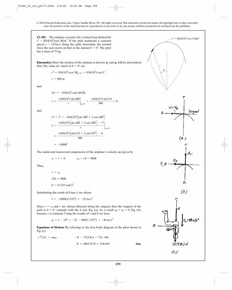
259
13–103. The airplane executes the vertical loop defined by. If the pilot maintains a constant
speed along the path, determine the normalforce the seat exerts on him at the instant . The pilothas a mass of 75 kg.
u = 0°v = 120 m>s
r2= [810(103)cos 2u] m2
Kinematics: Since the motion of the airplane is known, ar and will be determinedfirst. The value of r and at are
and
and
The radial and transversal components of the airplane’s velocity are given by
Thus,
Substituting the result of into , we obtain
Since and are always directed along the tangent, then the tangent of thepath at coincide with the axis, Fig. (a). As a result , Fig. (b),because is constant. Using the results of and , we have
Equations of Motion: By referring to the free-body diagram of the pilot shown inFig. (c),
Ans. N = 2864.25 N = 2.86 kN
+ c ©Fr = mar; -N - 75(9.81) = 75(-48)
ar = r$
- ru#2
= -32 - 900(1.13332) = -48 m>s2
u#
r$
vau = at = 0uu = 0°
vv = vu
r$
= -1800(0.13332) = -32 m>s2
r$
u#
u#
= 0.1333 rad>s2
120 = 900u#
v = vu
vr = r#
= 0 vu = ru#
= 900u#
= -1800u#2
=
-810(103) Csin 0°u$
+ 2 cos 0°u#2 D - 0
900
r$
=
-810(103) Csin 2uu$
+ 2 cos 2uu#2 D - r
# 2
r`u= 0°
rr$
+ r# 2
= -810(103) Csin 2uu$
+ 2 cos 2uu#2 D
r#
=
-810(103) sin 2uu#
r2u= 0°
=
-810(103) sin 0°u
900= 0
2rr#
= -810(103) sin 2u(2u#
)
r = 900 m
r2= 810(103) cos 2u� u= 0° = 810(103) cos 0°
u = 0°u
au
© 2010 Pearson Education, Inc., Upper Saddle River, NJ. All rights reserved. This material is protected under all copyright laws as they currentlyexist. No portion of this material may be reproduced, in any form or by any means, without permission in writing from the publisher.
r
r2 � [810(103) cos 2 u]m2
u
91962_02_s13_p0177-0284 6/8/09 10:52 AM Page 259
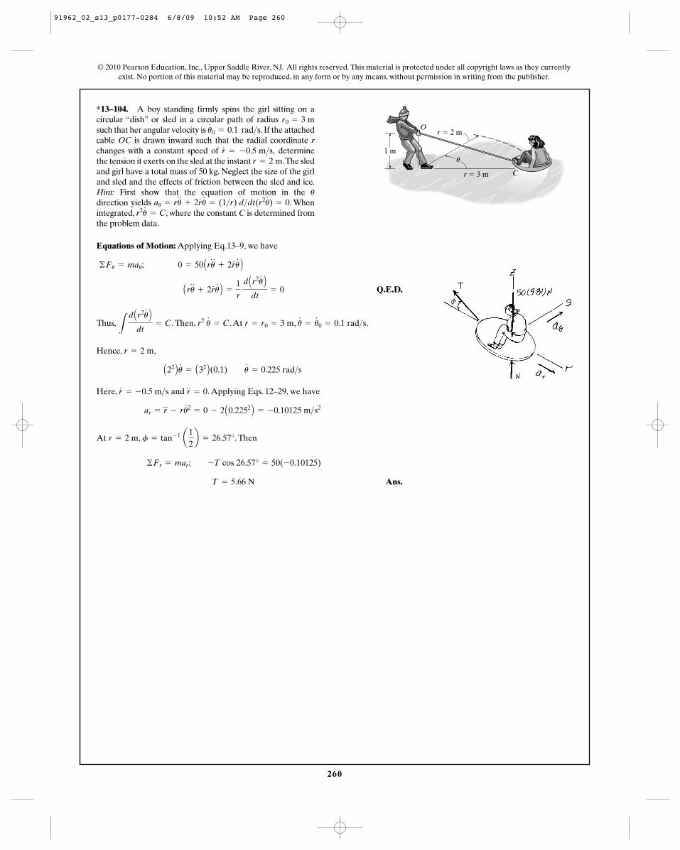
260
*13–104. A boy standing firmly spins the girl sitting on acircular “dish” or sled in a circular path of radius such that her angular velocity is . If the attachedcable OC is drawn inward such that the radial coordinate rchanges with a constant speed of determinethe tension it exerts on the sled at the instant .The sledand girl have a total mass of 50 kg. Neglect the size of the girland sled and the effects of friction between the sled and ice.Hint: First show that the equation of motion in the direction yields . Whenintegrated, , where the constant C is determined fromthe problem data.
r2u#
= Cau = ru
$
+ 2r#
u#
= (1>r) d>dt(r2u#
) = 0u
r = 2 mr#
= -0.5 m>s,
u#
0 = 0.1 rad>sr0 = 3 m
© 2010 Pearson Education, Inc., Upper Saddle River, NJ. All rights reserved. This material is protected under all copyright laws as they currentlyexist. No portion of this material may be reproduced, in any form or by any means, without permission in writing from the publisher.
Equations of Motion: Applying Eq.13–9, we have
Q.E.D.
Thus, . Then, . At , .
Hence, ,
Here, and . Applying Eqs. 12–29, we have
At , . Then
Ans. T = 5.66 N
©Fr = mar; -T cos 26.57° = 50(-0.10125)
f = tan- 1 a12b = 26.57°r = 2 m
ar = r$
- ru#2
= 0 - 2 A0.2252 B = -0.10125 m>s2
r$
= 0r#
= -0.5 m>s
A22 Bu#
= A32 B(0.1) u#
= 0.225 rad>s
r = 2 m
u#
= u#
0 = 0.1 rad>sr = r0 = 3 mr2 u#
= CL
d Ar2u#
B
dt= C
Aru$
+ 2r#
u#
B =
1r
d Ar2u
#
B
dt= 0
©Fu = mau; 0 = 50 Aru$
+ 2r#
u#
B
C
u
Or � 2 m
r � 3 m
1 m
91962_02_s13_p0177-0284 6/8/09 10:52 AM Page 260
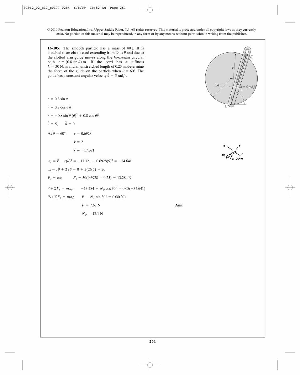
261
13–105. The smooth particle has a mass of It isattached to an elastic cord extending from O to P and due tothe slotted arm guide moves along the horizontal circularpath If the cord has a stiffness
and an unstretched length of 0.25 m, determinethe force of the guide on the particle when Theguide has a constant angular velocity u
#
= 5 rad>s.u = 60°.
k = 30 N>mr = 10.8 sin u2 m.
80 g.
At
Ans.
NP = 12.1 N
F = 7.67 N
a+ ©Fu = mau; F - NP sin 30° = 0.08(20)
Q+ ©Fr = m ar; -13.284 + NP cos 30° = 0.08(-34.641)
Fs = ks; Fs = 30(0.6928 - 0.25) = 13.284 N
au = ru$
+ 2 r#
u#
= 0 + 2(2)(5) = 20
ar = r$
- r(u#
)2= -17.321 - 0.6928(5)2
= -34.641
r$
= -17.321
r#
= 2
u = 60°, r = 0.6928
u#
= 5, u$
= 0
r$
= -0.8 sin u (u#
)2+ 0.8 cos uu
$
r#
= 0.8 cos u u#
r = 0.8 sin u
© 2010 Pearson Education, Inc., Upper Saddle River, NJ. All rights reserved. This material is protected under all copyright laws as they currentlyexist. No portion of this material may be reproduced, in any form or by any means, without permission in writing from the publisher.
P
r
O
u � 5 rad/s ·0.4 m
u
91962_02_s13_p0177-0284 6/8/09 10:52 AM Page 261
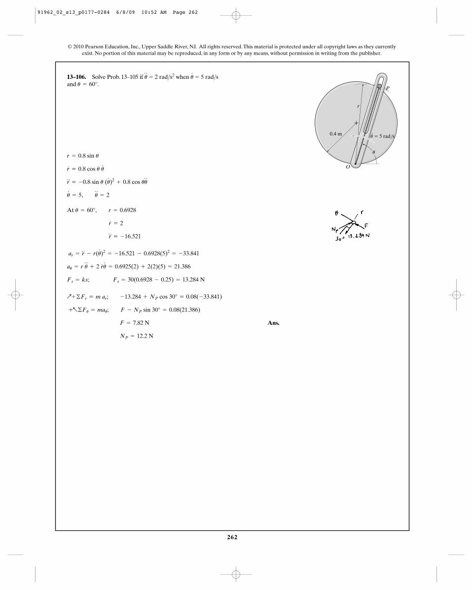
262
© 2010 Pearson Education, Inc., Upper Saddle River, NJ. All rights reserved. This material is protected under all copyright laws as they currentlyexist. No portion of this material may be reproduced, in any form or by any means, without permission in writing from the publisher.
13–106. Solve Prob. 13–105 if when and u = 60°.
u#
= 5 rad>su$
= 2 rad>s2
At
Ans.
NP = 12.2 N
F = 7.82 N
+a©Fu = mau; F - NP sin 30° = 0.08(21.386)
Q+ ©Fr = m ar; -13.284 + NP cos 30° = 0.08(-33.841)
Fs = ks; Fs = 30(0.6928 - 0.25) = 13.284 N
au = r u$
+ 2 r#
u#
= 0.6925(2) + 2(2)(5) = 21.386
ar = r$
- r(u#
)2= -16.521 - 0.6928(5)2
= -33.841
r$
= -16.521
r#
= 2
u = 60°, r = 0.6928
u#
= 5, u$
= 2
r$
= -0.8 sin u (u#
)2+ 0.8 cos uu
$
r#
= 0.8 cos u u#
r = 0.8 sin u
P
r
O
u � 5 rad/s ·0.4 m
u
91962_02_s13_p0177-0284 6/8/09 10:52 AM Page 262
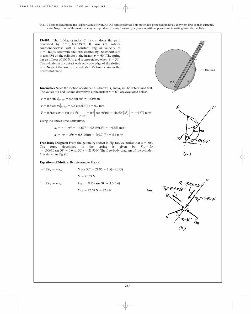
263
13–107. The 1.5-kg cylinder C travels along the pathdescribed by . If arm OA rotatescounterclockwise with a constant angular velocity of
, determine the force exerted by the smooth slotin arm OA on the cylinder at the instant . The springhas a stiffness of 100 N m and is unstretched when .The cylinder is in contact with only one edge of the slottedarm. Neglect the size of the cylinder. Motion occurs in thehorizontal plane.
u = 30°>u = 60°
u#
= 3 rad>s
r = (0.6 sin u) m
Kinematics: Since the motion of cylinder C is known, ar and will be determined first.The values of r and its time derivatives at the instant are evaluated below.
Using the above time derivatives,
Free-Body Diagram: From the geometry shown in Fig. (a), we notice that .The force developed in the spring is given by
. The free-body diagram of the cylinderC is shown in Fig. (b).
Equations of Motion: By referring to Fig. (a),
Ans. FOA = 12.68 N = 12.7 N
a+ ©Fu = mau; FOA - 9.159 sin 30° = 1.5(5.4)
N = 9.159 N
+Q©Fr = mar; N cos 30° - 21.96 = 1.5(-9.353)
= 100(0.6 sin 60° - 0.6 sin 30°) = 21.96 NFsp = ksa = 30°
au = ru$
+ 2r#
u#
= 0.5196(0) + 2(0.9)(3) = 5.4 m>s2
ar = r$
- ru#2
= -4.677 - 0.5196(32) = -9.353 m>s2
r$
= 0.6(cos uu$
- sin u Au#
B2) 2u= 60°
= 0.6 ccos 60°(0) - sin 60° A32 B d = -4.677 m>s2
r#
= 0.6 cos uu#
� u= 60° = 0.6 cos 60°(3) = 0.9 m>s
r = 0.6 sin u|u= 60° = 0.6 sin 60° = 0.5196 m
u = 60°au
© 2010 Pearson Education, Inc., Upper Saddle River, NJ. All rights reserved. This material is protected under all copyright laws as they currentlyexist. No portion of this material may be reproduced, in any form or by any means, without permission in writing from the publisher.
A
O
C
r � 0.6 sin u
uu, u
91962_02_s13_p0177-0284 6/8/09 10:53 AM Page 263
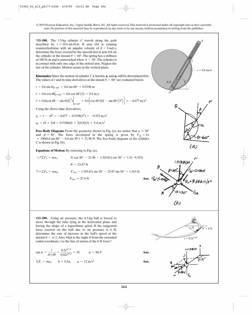
264
*13–108. The 1.5-kg cylinder C travels along the pathdescribed by . If arm OA is rotatingcounterclockwise with an angular velocity of ,determine the force exerted by the smooth slot in arm OA onthe cylinder at the instant . The spring has a stiffnessof 100 N m and is unstretched when .The cylinder isin contact with only one edge of the slotted arm. Neglect thesize of the cylinder. Motion occurs in the vertical plane.
u = 30°>u = 60°
u#
= 3 rad>sr = (0.6 sin u) m
© 2010 Pearson Education, Inc., Upper Saddle River, NJ. All rights reserved. This material is protected under all copyright laws as they currentlyexist. No portion of this material may be reproduced, in any form or by any means, without permission in writing from the publisher.
Kinematics: Since the motion of cylinder C is known, ar and will be determined first.The values of r and its time derivatives at the instant are evaluated below.
Using the above time derivatives,
Free-Body Diagram: From the geometry shown in Fig. (a), we notice that and . The force developed in the spring is given by
. The free-body diagram of the cylinderC is shown in Fig. (b).
Equations of Motion: By referring to Fig. (a),
Ans. FOA = 27.4 N
a+ ©Fu = mau; FOA - 1.5(9.81) sin 30° - 23.87 sin 30° = 1.5(5.4)
N = 23.87 N
+Q©Fr = mar; N cos 30° - 21.96 - 1.5(9.81) cos 30° = 1.5(-9.353)
= 100(0.6 sin 60° - 0.6 sin 30°) = 21.96 NFsp = ksb = 30°a = 30°
au = ru$
+ 2r#
u#
= 0.5196(0) + 2(0.9)(3) = 5.4 m>s2
ar = r$
- ru#2
= -4.677 - 0.5196(32) = -9.353 m>s2
r$
= 0.6(cos uu$
- sin u Au#
B2) 2u= 60°
= 0.6 ccos 60°(0) - sin 60° A32 B d = -4.677 m>s2
r#
= 0.6 cos uu#
� u= 60° = 0.6 cos 60°(3) = 0.9 m>s
r = 0.6 sin u|u= 60° = 0.6 sin 60° = 0.5196 m
0 = 60°au
A
O
C
r � 0.6 sin u
uu, u
•13–109. Using air pressure, the 0.5-kg ball is forced tomove through the tube lying in the horizontal plane andhaving the shape of a logarithmic spiral. If the tangentialforce exerted on the ball due to air pressure is 6 N,determine the rate of increase in the ball’s speed at theinstant .Also, what is the angle from the extendedradial coordinate r to the line of action of the 6-N force?
cu = p>2
Ans.
Ans.©Ft = mat; 6 = 0.5at at = 12 m>s2
tan c =
r
dr>du=
0.2e0.1 u
0.02e0.1u = 10 c = 84.3°
F � 6 Nu
r � 0.2e0.1u
r
91962_02_s13_p0177-0284 6/8/09 10:53 AM Page 264
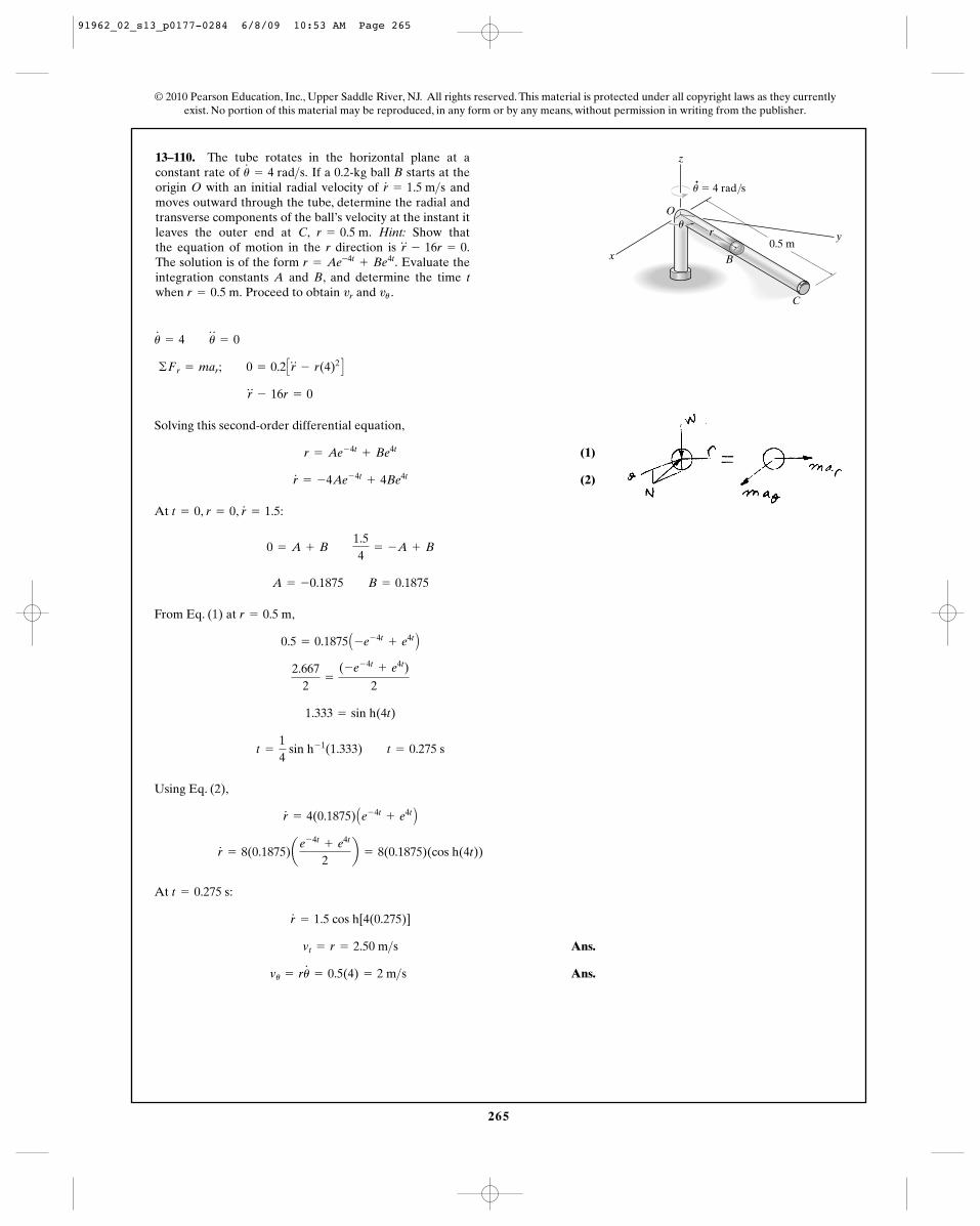
265
© 2010 Pearson Education, Inc., Upper Saddle River, NJ. All rights reserved. This material is protected under all copyright laws as they currentlyexist. No portion of this material may be reproduced, in any form or by any means, without permission in writing from the publisher.
13–110. The tube rotates in the horizontal plane at aconstant rate of If a 0.2-kg ball B starts at theorigin O with an initial radial velocity of andmoves outward through the tube, determine the radial andtransverse components of the ball’s velocity at the instant itleaves the outer end at C, Hint: Show that the equation of motion in the r direction is The solution is of the form Evaluate theintegration constants A and B, and determine the time twhen Proceed to obtain and vu .vrr = 0.5 m.
r = Ae-4t+ Be4t.
r$
- 16r = 0.r = 0.5 m.
r#
= 1.5 m>su#
= 4 rad>s.
Solving this second-order differential equation,
(1)
(2)
At , , :
From Eq. (1) at ,
Using Eq. (2),
At :
Ans.
Ans.vu = ru#
= 0.5(4) = 2 m>s vt = r = 2.50 m>s
r#
= 1.5 cos h[4(0.275)]
t = 0.275 s
r#
= 8(0.1875)ae- 4t
+ e4t
2b = 8(0.1875)(cos h(4t))
r#
= 4(0.1875) Ae- 4t+ e4t B
t =
14
sin h- 1(1.333) t = 0.275 s
1.333 = sin h(4t)
2.6672
=
(-e- 4t+ e4t)
2
0.5 = 0.1875 A -e- 4t+ e4t B
r = 0.5 m
A = -0.1875 B = 0.1875
0 = A + B 1.54
= -A + B
r#
= 1.5r = 0t = 0
r#
= -4Ae- 4t+ 4Be4t
r = Ae- 4t+ Be4t
r$
- 16r = 0
©Fr = mar; 0 = 0.2 Cr$
- r(4)2 D
u#
= 4 u$
= 0
r
Bx
y
z
0.5 m
·
� 4 rad/s
C
O
u
u
91962_02_s13_p0177-0284 6/8/09 10:53 AM Page 265
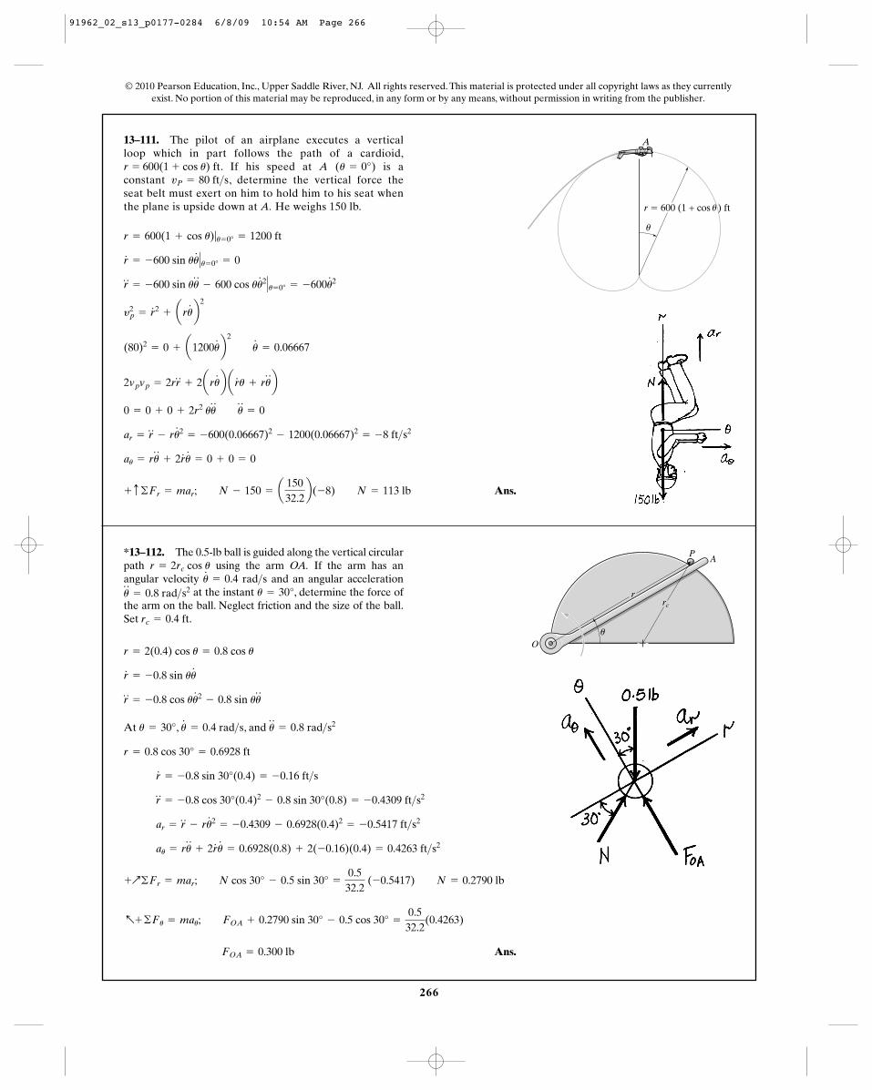
266
© 2010 Pearson Education, Inc., Upper Saddle River, NJ. All rights reserved. This material is protected under all copyright laws as they currentlyexist. No portion of this material may be reproduced, in any form or by any means, without permission in writing from the publisher.
13–111. The pilot of an airplane executes a vertical loop which in part follows the path of a cardioid,
. If his speed at A ( ) is aconstant , determine the vertical force theseat belt must exert on him to hold him to his seat whenthe plane is upside down at A. He weighs 150 lb.
vP = 80 ft>su = 0°r = 600(1 + cos u) ft
Ans.+ c ©Fr = mar; N - 150 = a15032.2b(-8) N = 113 lb
au = ru$
+ 2r#
u#
= 0 + 0 = 0
ar = r$
- ru#2
= -600(0.06667)2- 1200(0.06667)2
= -8 ft>s2
0 = 0 + 0 + 2r2 uu$ u
$
= 0
2vpvp = 2rr$
+ 2aru#
b ar#
u + ru$
b
(80)2= 0 + a1200u
#
b2 u
#
= 0.06667
y2p = r
# 2+ aru
#
b2
r$
= -600 sin uu$
- 600 cos uu#2� u= 0° = -600u
#2
r#
= -600 sin uu#
� u= 0° = 0
r = 600(1 + cos u)|u= 0° = 1200 ft
A
u
ur � 600 (1 + cos ) ft
*13–112. The 0.5-lb ball is guided along the vertical circularpath using the arm OA. If the arm has anangular velocity and an angular acceleration
at the instant , determine the force ofthe arm on the ball. Neglect friction and the size of the ball.Set .rc = 0.4 ft
u = 30°u$
= 0.8 rad>s2u#
= 0.4 rad>sr = 2rc cos u
At , , and
Ans. FOA = 0.300 lb
a+ ©Fu = mau; FOA + 0.2790 sin 30° - 0.5 cos 30° =
0.532.2
(0.4263)
+Q©Fr = mar; N cos 30° - 0.5 sin 30° =
0.532.2
(-0.5417) N = 0.2790 lb
au = ru$
+ 2r#
u#
= 0.6928(0.8) + 2(-0.16)(0.4) = 0.4263 ft>s2
ar = r$
- ru#2
= -0.4309 - 0.6928(0.4)2= -0.5417 ft>s2
r$
= -0.8 cos 30°(0.4)2- 0.8 sin 30°(0.8) = -0.4309 ft>s2
r#
= -0.8 sin 30°(0.4) = -0.16 ft>s
r = 0.8 cos 30° = 0.6928 ft
u$
= 0.8 rad>s2u#
= 0.4 rad>su = 30°
r$
= -0.8 cos uu#2
- 0.8 sin uu$
r#
= -0.8 sin uu#
r = 2(0.4) cos u = 0.8 cos u
P
r
u
A
O
rc
91962_02_s13_p0177-0284 6/8/09 10:54 AM Page 266
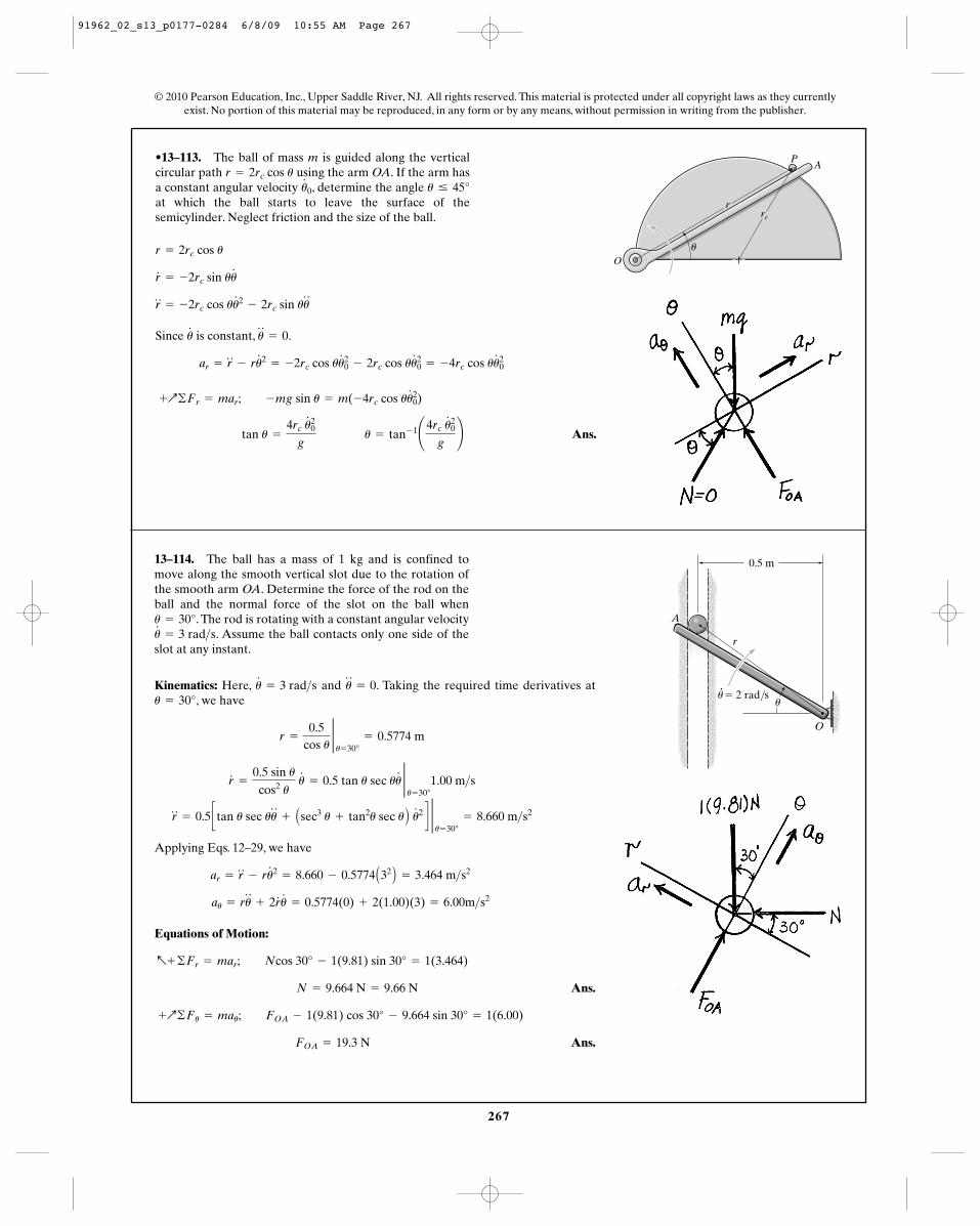
P
r
u
A
O
rc
267
•13–113. The ball of mass m is guided along the verticalcircular path using the arm OA. If the arm hasa constant angular velocity , determine the angle at which the ball starts to leave the surface of thesemicylinder. Neglect friction and the size of the ball.
u … 45°u#
0
r = 2rc cos u
Since is constant, .
Ans. tan u =
4rc u#20
g u = tan- 1¢4rc u
#20
g≤
+Q©Fr = mar; -mg sin u = m(-4rc cos uu#20)
ar = r$
- ru#2
= -2rc cos uu#20 - 2rc cos uu
#20 = -4rc cos uu
#20
u$
= 0u#
r$
= -2rc cos uu#2
- 2rc sin uu$
r#
= -2rc sin uu#
r = 2rc cos u
© 2010 Pearson Education, Inc., Upper Saddle River, NJ. All rights reserved. This material is protected under all copyright laws as they currentlyexist. No portion of this material may be reproduced, in any form or by any means, without permission in writing from the publisher.
P
r
u
A
O
rc
13–114. The ball has a mass of 1 kg and is confined tomove along the smooth vertical slot due to the rotation ofthe smooth arm OA. Determine the force of the rod on theball and the normal force of the slot on the ball when
. The rod is rotating with a constant angular velocity. Assume the ball contacts only one side of the
slot at any instant.u#
= 3 rad>su = 30°
Kinematics: Here, and . Taking the required time derivatives at, we have
Applying Eqs. 12–29, we have
Equations of Motion:
Ans.
Ans. FOA = 19.3 N
+Q©Fu = mau; FOA - 1(9.81) cos 30° - 9.664 sin 30° = 1(6.00)
N = 9.664 N = 9.66 N
a+ ©Fr = mar; Ncos 30° - 1(9.81) sin 30° = 1(3.464)
au = ru$
+ 2r#
u#
= 0.5774(0) + 2(1.00)(3) = 6.00m>s2
ar = r$
- ru#2
= 8.660 - 0.5774 A32 B = 3.464 m>s2
r$
= 0.5 ctan u sec uu$
+ Asec3 u + tan2u sec u B u#2 d 2u= 30°
= 8.660 m>s2
r#
=
0.5 sin ucos2 u
u#
= 0.5 tan u sec uu# 2u= 30°
1.00 m>s
r =
0.5cos u
2u= 30°
= 0.5774 m
u = 30°u$
= 0u#
= 3 rad>s
0.5 m
O
uu� 2 rad/s
A
r
91962_02_s13_p0177-0284 6/8/09 10:55 AM Page 267
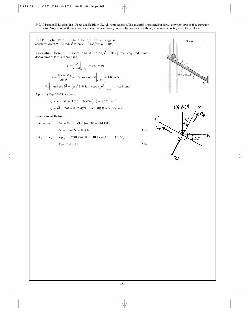
268
© 2010 Pearson Education, Inc., Upper Saddle River, NJ. All rights reserved. This material is protected under all copyright laws as they currentlyexist. No portion of this material may be reproduced, in any form or by any means, without permission in writing from the publisher.
13–115. Solve Prob. 13–114 if the arm has an angularacceleration of when at .u = 30°u
#
= 3 rad>su$
= 2 rad>s2
Kinematics: Here, and . Taking the required timederivatives at , we have
Applying Eqs. 12–29, we have
Equations of Motion:
Ans.
Ans. FOA = 20.9 N
©Fu = mau; FOA - 1(9.81)cos 30° - 10.43 sin30° = 1(7.155)
N = 10.43 N = 10.4 N
©Fr = mar; Ncos 30° - 1(9.81)sin 30° = 1(4.131)
au = ru$
+ 2r#
u#
= 0.5774(2) + 2(1.00)(3) = 7.155 m>s2
ar = r$
- ru#2
= 9.327 - 0.5774 A32 B = 4.131 m>s2
r$
= 0.5 c tan u sec uu$
+ Asec2 u + tan2u sec u B u#2 d 2u= 30°
= 9.327 m>s2
r#
=
0.5 sin ucos2u
u#
= 0.5 tan u sec uu# 2u= 30°
= 1.00 m>s
r =
0.5cos u
2u= 30°
= 0.5774 m
u = 30°u$
= 2 rad>s2u#
= 3 rad>s
0.5 m
O
uu� 2 rad/s
A
r
91962_02_s13_p0177-0284 6/8/09 10:55 AM Page 268
269
© 2010 Pearson Education, Inc., Upper Saddle River, NJ. All rights reserved. This material is protected under all copyright laws as they currentlyexist. No portion of this material may be reproduced, in any form or by any means, without permission in writing from the publisher.
*13–116. Prove Kepler’s third law of motion. Hint: UseEqs. 13–19, 13–28, 13–29, and 13–31.
From Eq. 13–19,
For and ,
Eliminating C, from Eqs. 13–28 and 13–29,
From Eq. 13–31,
Thus,
Q.E.D.T2= a
4p2
GMsba3
4p2a3
T2h2 =
GMs
h2
b2=
T2h2
4p2a2
T =
p
h (2a)(b)
2a
b2 =
2GMs
h2
1ra
= -C +
GMs
h2
1rp
= C +
GMs
h2
u = 180°u = 0°
1r
= C cos u +
GMs
h2
91962_02_s13_p0177-0284 6/8/09 10:55 AM Page 269
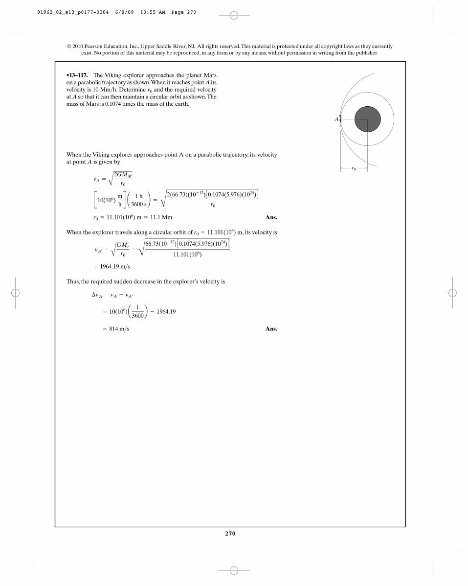
270
© 2010 Pearson Education, Inc., Upper Saddle River, NJ. All rights reserved. This material is protected under all copyright laws as they currentlyexist. No portion of this material may be reproduced, in any form or by any means, without permission in writing from the publisher.
•13–117. The Viking explorer approaches the planet Marson a parabolic trajectory as shown.When it reaches point A itsvelocity is 10 Mm h. Determine and the required velocityat A so that it can then maintain a circular orbit as shown.Themass of Mars is 0.1074 times the mass of the earth.
r0>
When the Viking explorer approaches point A on a parabolic trajectory, its velocityat point A is given by
Ans.
When the explorer travels along a circular orbit of , its velocity is
Thus, the required sudden decrease in the explorer’s velocity is
Ans. = 814 m>s
= 10(106)a1
3600b - 1964.19
¢vA = vA - vA¿
= 1964.19 m>s
vA¿=
A
GMr
r0=
D
66.73(10- 12) C0.1074(5.976)(1024) D
11.101(106)
r0 = 11.101(106) m
r0 = 11.101(106) m = 11.1 Mm
B10(106) mhR ¢ 1 h
3600 s≤ =
D
2(66.73)(10- 12) C0.1074(5.976)(1024) D
r0
vA =
A
2GMM
r0
A
r0
91962_02_s13_p0177-0284 6/8/09 10:55 AM Page 270
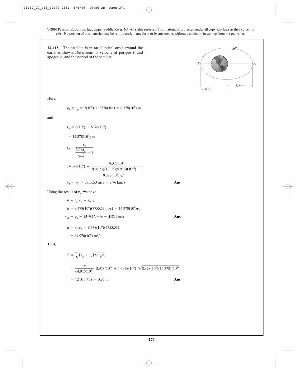
271
© 2010 Pearson Education, Inc., Upper Saddle River, NJ. All rights reserved. This material is protected under all copyright laws as they currentlyexist. No portion of this material may be reproduced, in any form or by any means, without permission in writing from the publisher.
13–118. The satellite is in an elliptical orbit around theearth as shown. Determine its velocity at perigee P andapogee A, and the period of the satellite.
AP
2 Mm8 Mm
Here,
and
Ans.
Using the result of vp, we have
Ans.
Thus,
Ans.= 12 075.71 s = 3.35 hr
=
p
64.976(109) C8.378(106) + 14.378(106) D28.378(106)(14.378)(106)
T =
p
h Arp + ra B2rp ra
= 64.976(109) m2>s
h = rp vp = 8.378(106)(7755.53)
vA = va = 4519.12 m>s = 4.52 km>s
h = 8.378(106)(7755.53 m>s) = 14.378(106)va
h = rp vp = ra va
vp = v0 = 7755.53 m>s = 7.76 km>s
14.378(106) =
8.378(106)
2(66.73)(10- 12)(5.976)(1024)
8.378(106)v0 2
- 1
ra =
r0
2GMe
r0v20
- 1
= 14.378(106) m
ra = 8(106) + 6378(103)
r0 = rp = 2(106) + 6378(103) = 8.378(106) m
91962_02_s13_p0177-0284 6/8/09 10:56 AM Page 271
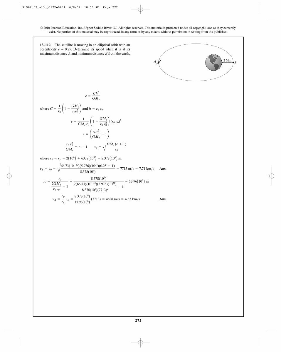
272
© 2010 Pearson Education, Inc., Upper Saddle River, NJ. All rights reserved. This material is protected under all copyright laws as they currentlyexist. No portion of this material may be reproduced, in any form or by any means, without permission in writing from the publisher.
13–119. The satellite is moving in an elliptical orbit with aneccentricity . Determine its speed when it is at itsmaximum distance A and minimum distance B from the earth.
e = 0.25
.
where .
Ans.
Ans.vA =
rp
ra vB =
8.378(106)
13.96(106) (7713) = 4628 m>s = 4.63 km>s
ra =
r0
2GMe
r0 v0- 1
=
8.378(106)
2(66.73)(10- 12)(5.976)(1024)
8.378(106)(7713)2- 1
= 13.96 A106 B m
vB = v0 =
C
66.73(10- 12)(5.976)(1024)(0.25 + 1)
8.378(106)= 7713 m>s = 7.71 km>s
r0 = rp = 2 A106 B + 6378 A103 B = 8.378 A106 B m
r0 v20
GMe= e + 1 v0 =
B
GMe (e + 1)
r0
e = ¢ r0 v20
GMe- 1≤
e =
1GMe r0
¢1 -
GMe
r0 v20≤ (r0 v0)
2
where C =
1r0
¢1 -
GMe
r0v20≤ and h = r0 v0
e =
Ch2
GMe
BA 2 Mm
91962_02_s13_p0177-0284 6/8/09 10:56 AM Page 272
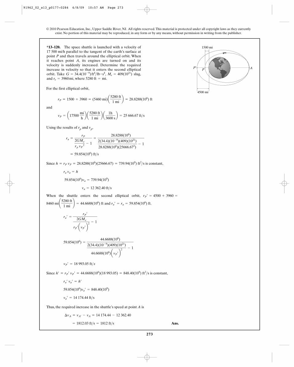
273
© 2010 Pearson Education, Inc., Upper Saddle River, NJ. All rights reserved. This material is protected under all copyright laws as they currentlyexist. No portion of this material may be reproduced, in any form or by any means, without permission in writing from the publisher.
*13–120. The space shuttle is launched with a velocity of17 500 mi/h parallel to the tangent of the earth’s surface atpoint P and then travels around the elliptical orbit. Whenit reaches point A, its engines are turned on and itsvelocity is suddenly increased. Determine the requiredincrease in velocity so that it enters the second ellipticalorbit. Take , slug,and , where 5280 ft mi.=re = 3960 mi
Me = 409(1021)G = 34.4(10- 9) ft4>lb # s4
P¿
4500 mi
1500 mi
P A
For the first elliptical orbit,
and
Using the results of rp and vp,
Since is constant,
When the shuttle enters the second elliptical orbit,
and .
Since is constant,
Thus, the required increase in the shuttle’s speed at point A is
Ans. = 1812.03 ft>s = 1812 ft>s
¢vA = vA¿- vA = 14 174.44 - 12 362.40
va¿ = 14 174.44 ft>s
59.854(106)va¿ = 848.40(109)
ra¿ va¿ = h¿
h¿ = rP¿ vP¿ = 44.6688(106)(18 993.05) = 848.40(109) ft2>s
vP¿ = 18 993.05 ft>s
59.854(106) =
44.6688(106)
2(34.4)(10- 9)(409)(1021)
44.6688(106)avP¿ b2 - 1
ra¿ =
rP¿
2GMe
rP¿ avP¿ b2 - 1
ra¿ = ra = 59.854(106) ft8460 mi¢5280 ft1 mi
≤ = 44.6688(106) ft
rP¿ = 4500 + 3960 =
va = 12 362.40 ft>s
59.854(106)va = 739.94(109)
ra va = h
h = rP vP = 28.8288(106)(25666.67) = 739.94(109) ft2>s
= 59.854(106) ft>s
ra =
rP
2GMe
rp vP 2 - 1
=
28.8288(106)
2(34.4)(10- 9)(409)(1021)
28.8288(106)(25666.672)- 1
vP = a17500 mihb a
5280 ft1 mi
b a1h
3600 sb = 25 666.67 ft>s
rP = 1500 + 3960 = (5460 mi)a5280 ft
1 mib = 28.8288(106) ft
91962_02_s13_p0177-0284 6/8/09 10:57 AM Page 273
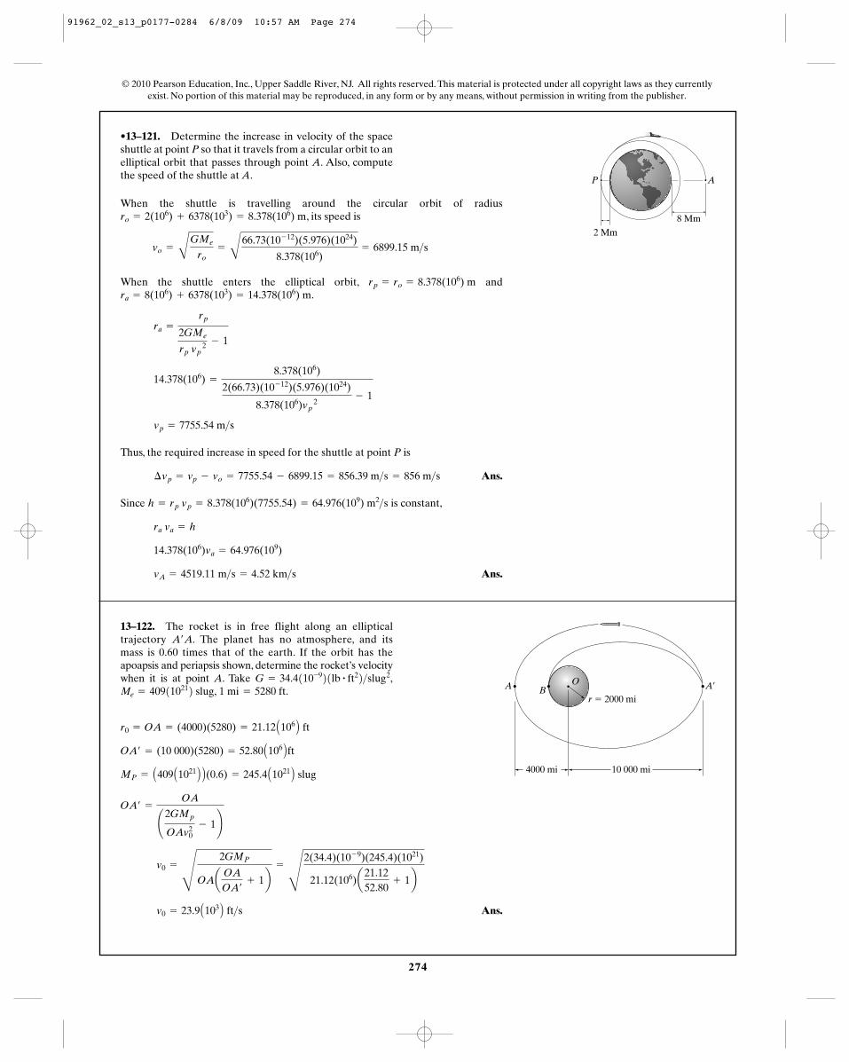
274
© 2010 Pearson Education, Inc., Upper Saddle River, NJ. All rights reserved. This material is protected under all copyright laws as they currentlyexist. No portion of this material may be reproduced, in any form or by any means, without permission in writing from the publisher.
•13–121. Determine the increase in velocity of the spaceshuttle at point P so that it travels from a circular orbit to anelliptical orbit that passes through point A. Also, computethe speed of the shuttle at A.
When the shuttle is travelling around the circular orbit of radius, its speed is
When the shuttle enters the elliptical orbit, and.
Thus, the required increase in speed for the shuttle at point P is
Ans.
Since is constant,
Ans.vA = 4519.11 m>s = 4.52 km>s
14.378(106)va = 64.976(109)
ra va = h
h = rp vp = 8.378(106)(7755.54) = 64.976(109) m2>s
¢vp = vp - vo = 7755.54 - 6899.15 = 856.39 m>s = 856 m>s
vp = 7755.54 m>s
14.378(106) =
8.378(106)
2(66.73)(10- 12)(5.976)(1024)
8.378(106)vp 2
- 1
ra =
rp
2GMe
rp vp 2 - 1
ra = 8(106) + 6378(103) = 14.378(106) mrp = ro = 8.378(106) m
vo =
B
GMe
ro=
B
66.73(10- 12)(5.976)(1024)
8.378(106)= 6899.15 m>s
ro = 2(106) + 6378(103) = 8.378(106) m 8 Mm2 Mm
AP
13–122. The rocket is in free flight along an ellipticaltrajectory The planet has no atmosphere, and itsmass is 0.60 times that of the earth. If the orbit has theapoapsis and periapsis shown, determine the rocket’s velocitywhen it is at point A. Take
1 mi = 5280 ft.Me = 409110212 slug,G = 34.4110-921lb # ft22>slug2,
A¿A.
Ans.v0 = 23.9 A103 B ft>s
v0 =
R
2GMP
OAaOA
OA¿
+ 1b=
R
2(34.4)(10- 9)(245.4)(1021)
21.12(106)a21.1252.80
+ 1b
OA¿ =
OA
¢2GMp
OAv20
- 1≤
MP = A409 A1021 B B(0.6) = 245.4 A1021 B slug
OA¿ = (10 000)(5280) = 52.80 A106 B ft
r0 = OA = (4000)(5280) = 21.12 A106 B ft
A¿r � 2000 mi
BOA
4000 mi 10 000 mi
91962_02_s13_p0177-0284 6/8/09 10:57 AM Page 274
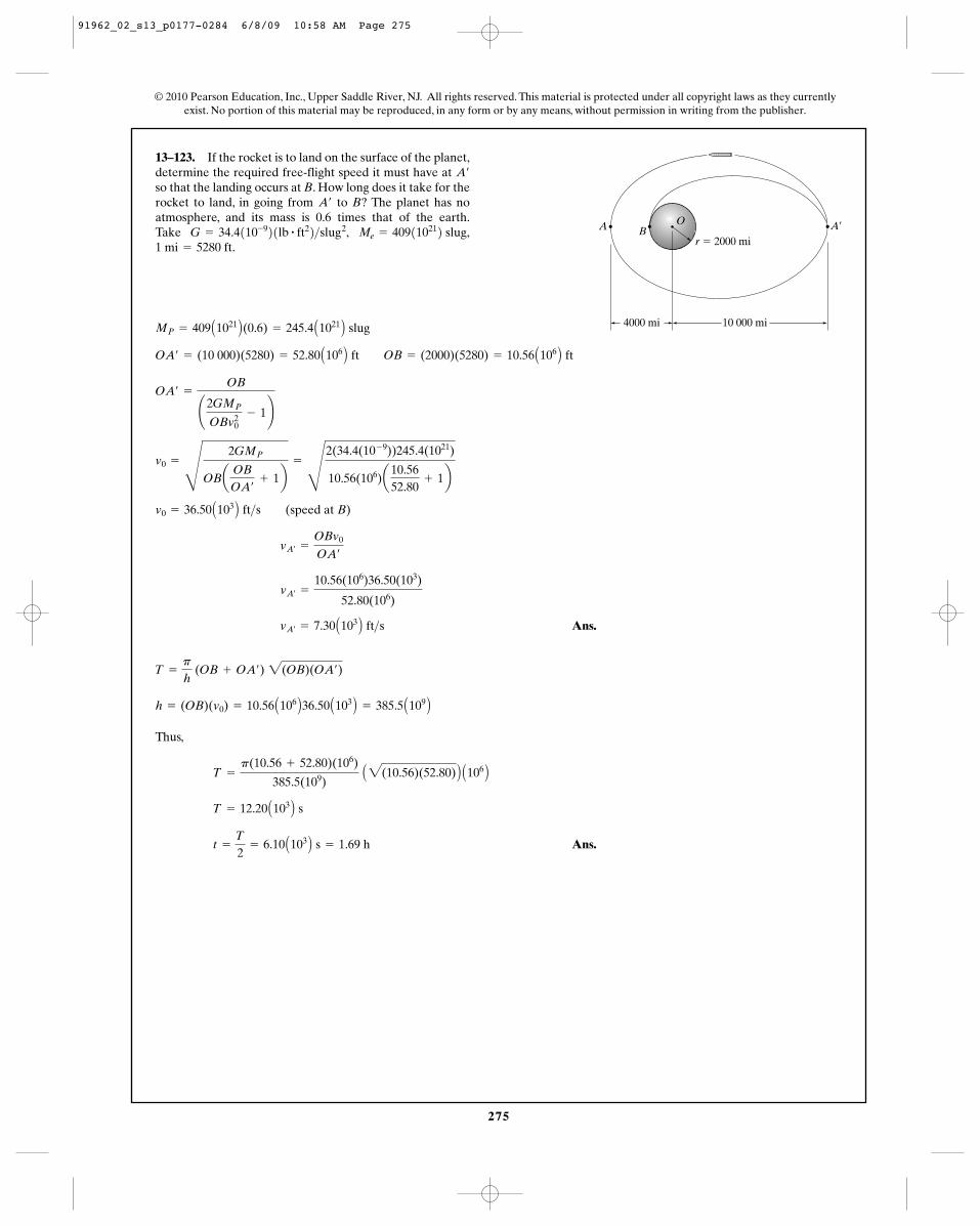
A¿r � 2000 mi
BOA
4000 mi 10 000 mi
275
13–123. If the rocket is to land on the surface of the planet,determine the required free-flight speed it must have at so that the landing occurs at B. How long does it take for therocket to land, in going from to B? The planet has noatmosphere, and its mass is 0.6 times that of the earth.Take 1 mi = 5280 ft.
Me = 409110212 slug,G = 34.4110-921lb # ft22>slug2,
A¿
A¿
Ans.
Thus,
Ans.t =
T
2= 6.10 A103 B s = 1.69 h
T = 12.20 A103 B s
T =
p(10.56 + 52.80)(106)
385.5(109) A2(10.56)(52.80) B A106 B
h = (OB)(v0) = 10.56 A106 B36.50 A103 B = 385.5 A109 B
T =
p
h (OB + OA¿) 2(OB)(OA¿)
vA¿= 7.30 A103 B ft>s
vA¿=
10.56(106)36.50(103)
52.80(106)
vA¿=
OBv0
OA¿
v0 = 36.50 A103 B ft>s (speed at B)
v0 =
S
2GMP
OBaOB
OA¿
+ 1b=
S
2(34.4(10- 9))245.4(1021)
10.56(106)a10.5652.80
+ 1b
OA¿ =
OB
¢2GMP
OBv20
- 1≤
OA¿ = (10 000)(5280) = 52.80 A106 B ft OB = (2000)(5280) = 10.56 A106 B ft
MP = 409 A1021 B(0.6) = 245.4 A1021 B slug
© 2010 Pearson Education, Inc., Upper Saddle River, NJ. All rights reserved. This material is protected under all copyright laws as they currentlyexist. No portion of this material may be reproduced, in any form or by any means, without permission in writing from the publisher.
A¿r � 2000 mi
BOA
4000 mi 10 000 mi
91962_02_s13_p0177-0284 6/8/09 10:58 AM Page 275
276
© 2010 Pearson Education, Inc., Upper Saddle River, NJ. All rights reserved. This material is protected under all copyright laws as they currentlyexist. No portion of this material may be reproduced, in any form or by any means, without permission in writing from the publisher.
*13–124. A communications satellite is to be placed intoan equatorial circular orbit around the earth so that italways remains directly over a point on the earth’s surface.If this requires the period to be 24 hours (approximately),determine the radius of the orbit and the satellite’s velocity.
Ans.
Ans.v =
2p(42.25)(106)
24(3600)= 3.07 km>s
r = 42.25(106) m = 42.2 Mm
66.73(10- 12)(5.976)(1024)
C2p
24(3600)D2
= r3
GMe
r= B 2pr
24(3600)R2
GMe
r= v2
GMeMs
r2 =
Ms v2
r
•13–125. The speed of a satellite launched into acircular orbit about the earth is given by Eq. 13–25.Determine the speed of a satellite launched parallel tothe surface of the earth so that it travels in a circular orbit800 km from the earth’s surface.
For a 800-km orbit
Ans. = 7453.6 m>s = 7.45 km>s
v0 =
B
66.73(10- 12)(5.976)(1024)(800 + 6378)(103)
91962_02_s13_p0177-0284 6/8/09 10:58 AM Page 276
277
© 2010 Pearson Education, Inc., Upper Saddle River, NJ. All rights reserved. This material is protected under all copyright laws as they currentlyexist. No portion of this material may be reproduced, in any form or by any means, without permission in writing from the publisher.
13–126. The earth has an orbit with eccentricityaround the sun. Knowing that the earth’s
minimum distance from the sun is , find thespeed at which a rocket travels when it is at this distance.Determine the equation in polar coordinates whichdescribes the earth’s orbit about the sun.
151.3(106) kme = 0.0821
Ans.
Ans.1r
= 0.502(10- 12) cos u + 6.11(10- 12)
1r
=
1151.3(109)
a1 -
66.73(10- 12)(1.99)(1030)
151.3(109)(30818)2 bcos u +
66.73(10- 12)(1.99)(1030)
C151.3(109) D2 (30818)2
1r
=
1r0
a1 -
GMS
r0 y20bcos u +
GMS
r20y
20
=
B
66.73(10- 12)(1.99)(1030)(0.0821 + 1)151.3(109)
= 30818 m>s = 30.8 km>s
y0 =
B
GMS (e + 1)
r0
e =
1GMS r0
¢1 -
GMS
r0 y20≤(r0y0)
2 e = ¢ r0 y20
GMS- 1≤ r0y
20
GMS= e + 1
e =
Ch2
GMS where C =
1r0
¢1 -
GMS
r0 y20≤ and h = r0 y0
13–127. A rocket is in a free-flight elliptical orbit about theearth such that the eccentricity of its orbit is e and its perigeeis . Determine the minimum increment of speed it shouldhave in order to escape the earth’s gravitational field when itis at this point along its orbit.
r0
To escape the earth’s gravitational field, the rocket has to make a parabolictrajectory.
Parabolic Trajectory:
Elliptical Orbit:
Ans. ¢y =
A2GMe
r0-
A
GMe (e + 1)r0
=
AGMe
r0 a22 - 21 + eb
r0 y
20
GMe= e + 1 y0 =
B
GMe (e + 1)
r0
e = ar0 y
20
GMe- 1b
e =
1GMe r0
¢1 -
GMe
r0 y20≤(r0 y0)
2
e =
Ch2
GMe where C =
1r0
¢1 -
GMe
r0y20≤ and h = r0 y0
ye =
A2GMe
r0
91962_02_s13_p0177-0284 6/8/09 10:59 AM Page 277
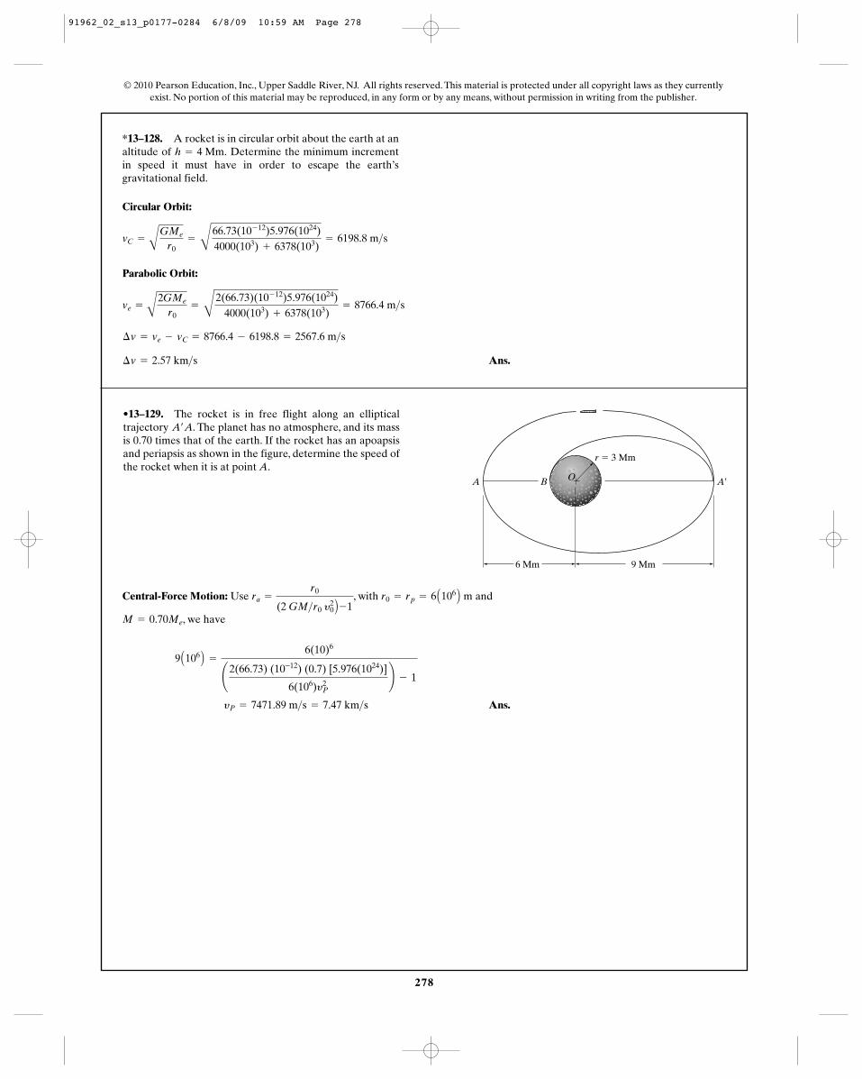
278
*13–128. A rocket is in circular orbit about the earth at analtitude of Determine the minimum incrementin speed it must have in order to escape the earth’sgravitational field.
h = 4 Mm.
© 2010 Pearson Education, Inc., Upper Saddle River, NJ. All rights reserved. This material is protected under all copyright laws as they currentlyexist. No portion of this material may be reproduced, in any form or by any means, without permission in writing from the publisher.
Circular Orbit:
Parabolic Orbit:
Ans.¢v = 2.57 km>s
¢v = ve - vC = 8766.4 - 6198.8 = 2567.6 m>s
ve =
A2GMe
r0=
B
2(66.73)(10- 12)5.976(1024)4000(103) + 6378(103)
= 8766.4 m>s
vC =
AGMe
r0=
B
66.73(10- 12)5.976(1024)4000(103) + 6378(103)
= 6198.8 m>s
•13–129. The rocket is in free flight along an ellipticaltrajectory . The planet has no atmosphere, and its massis 0.70 times that of the earth. If the rocket has an apoapsisand periapsis as shown in the figure, determine the speed ofthe rocket when it is at point A.
A¿A
6 Mm 9 Mm
BA A¿
r � 3 Mm
O
Central-Force Motion: Use , with and
, we have
Ans. yP = 7471.89 m>s = 7.47 km>s
9 A106 B =
6(10)6
¢2(66.73) (10-12) (0.7) [5.976(1024)]
6(106)y2P
≤ - 1
M = 0.70Me
r0 = rp = 6 A106 B mra =
r0
(2 GM>r0 y20 B -1
91962_02_s13_p0177-0284 6/8/09 10:59 AM Page 278
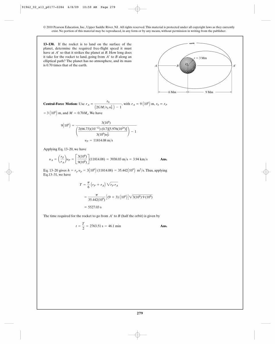
279
© 2010 Pearson Education, Inc., Upper Saddle River, NJ. All rights reserved. This material is protected under all copyright laws as they currentlyexist. No portion of this material may be reproduced, in any form or by any means, without permission in writing from the publisher.
13–130. If the rocket is to land on the surface of theplanet, determine the required free-flight speed it musthave at so that it strikes the planet at B. How long doesit take for the rocket to land, going from to B along anelliptical path? The planet has no atmosphere, and its massis 0.70 times that of the earth.
A¿
A¿
6 Mm 9 Mm
BA A¿
r � 3 Mm
O
Central-Force Motion: Use , with ,
, and . We have
Applying Eq. 13–20, we have
Ans.
Eq. 13–20 gives . Thus, applyingEq.13–31, we have
The time required for the rocket to go from to B (half the orbit) is given by
Ans.t =
T
2= 2763.51 s = 46.1 min
A¿
= 5527.03 s
=
p
35.442(109) C(9 + 3) A106 B D23(106) 9 (106)
T =
p
6 ArP + rA B 2rP rA
h = rp yp = 3 A106 B (11814.08) = 35.442 A109 B m2>s
yA = arP
rAbyP = B3(106)
9(106)R(11814.08) = 3938.03 m>s = 3.94 km>s
yP = 11814.08 m>s
9 A106 B =
3(106)
¢2(66.73)(10-12) (0.7)[5.976(1024)]
3(106)y2P
≤ - 1
M = 0.70Me= 3 A106 B m
r0 = rPrA = 9 A106 B mrA =
r0
A2GM>r0 y20 B - 1
91962_02_s13_p0177-0284 6/8/09 10:59 AM Page 279
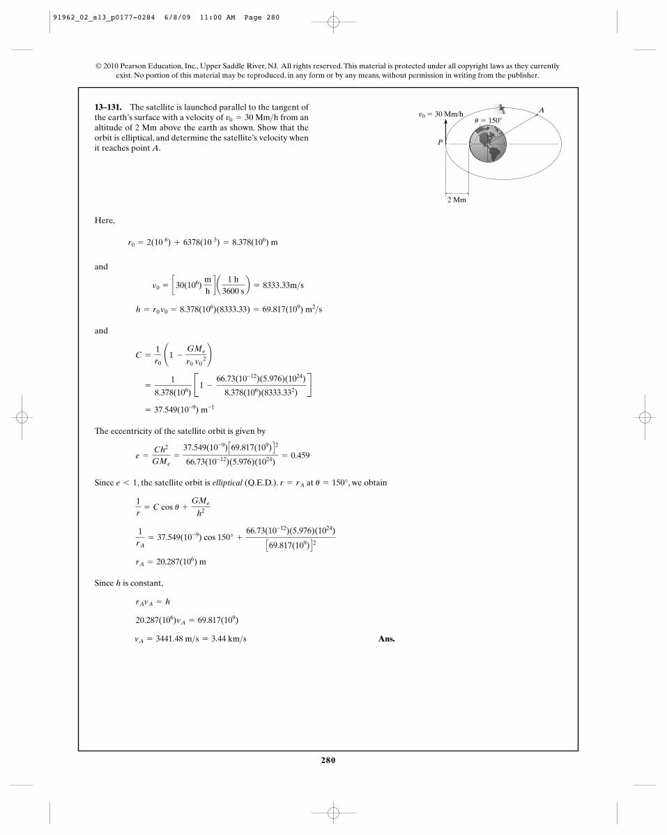
280
© 2010 Pearson Education, Inc., Upper Saddle River, NJ. All rights reserved. This material is protected under all copyright laws as they currentlyexist. No portion of this material may be reproduced, in any form or by any means, without permission in writing from the publisher.
13–131. The satellite is launched parallel to the tangent ofthe earth’s surface with a velocity of from analtitude of 2 Mm above the earth as shown. Show that theorbit is elliptical, and determine the satellite’s velocity whenit reaches point A.
v0 = 30 Mm>h
Here,
and
and
The eccentricity of the satellite orbit is given by
Since , the satellite orbit is elliptical (Q.E.D.). at , we obtain
Since h is constant,
Ans.vA = 3441.48 m>s = 3.44 km>s
20.287(106)vA = 69.817(109)
rAvA = h
rA = 20.287(106) m
1rA
= 37.549(10-9) cos 150° +
66.73(10-12)(5.976)(1024)
C69.817(109) D2
1r
= C cos u +
GMe
h2
u = 150°r = rAe 6 1
e =
Ch2
GMe=
37.549(10-9) C69.817(109) D2
66.73(10-12)(5.976)(1024)= 0.459
= 37.549(10-9) m-1
=
1
8.378(106) B1 -
66.73(10-12)(5.976)(1024)
8.378(106)(8333.332)R
C =
1r0
¢1 -
GMe
r0 v0
2 ≤
h = r0 v0 = 8.378(106)(8333.33) = 69.817(109) m2>s
v0 = c30(106) mhd a
1 h3600 s
b = 8333.33m>s
r0 = 2(10 6) + 6378(10 3) = 8.378(106) m
A
P
2 Mm
v0 � 30 Mm/hu � 150�
91962_02_s13_p0177-0284 6/8/09 11:00 AM Page 280
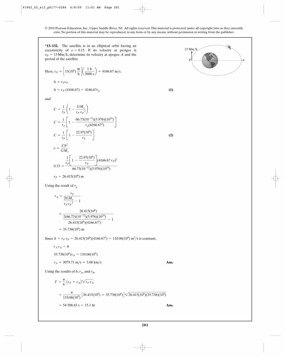
281
© 2010 Pearson Education, Inc., Upper Saddle River, NJ. All rights reserved. This material is protected under all copyright laws as they currentlyexist. No portion of this material may be reproduced, in any form or by any means, without permission in writing from the publisher.
*13–132. The satellite is in an elliptical orbit having aneccentricity of . If its velocity at perigee is
, determine its velocity at apogee A and theperiod of the satellite.vP = 15 Mm>h
e = 0.15
Here, .
(1)
and
(2)
Using the result of rp
Since is constant,
Ans.
Using the results of h, rA, and rP,
Ans. = 54 508.43 s = 15.1 hr
=
p
110.06(109) C26.415(106) + 35.738(106) D226.415(106)(35.738)(106)
T =
p
6 ArP + rA B2rP rA
vA = 3079.71 m>s = 3.08 km>s
35.738(106)vA = 110.06(109)
rA vA = h
h = rP vP = 26.415(106)(4166.672) = 110.06(109) m2>s
= 35.738(106) m
=
26.415(106)
2(66.73)(10-12)(5.976)(1024)
26.415(106)(4166.672)- 1
rA =
rP
2GMe
rP vP 2 - 1
rP = 26.415(106) m
0.15 =
1rPB1 -
22.97(106)
rPR(4166.67 rP)2
66.73(10-12)(5.976)(1024)
e =
Ch2
GMe
C =
1rP
B1 -
22.97(106)
rPR
C =
1rp
B1 -
66.73(10-12)(5.976)(1024)
rp(4166.672)R
C =
1rP
¢1 -
GMe
rP vP 2 ≤
h = rP (4166.67) = 4166.67rp
h = rPvP
vP = c15(106) mhd a
1 h3600 s
b = 4166.67 m>s
AP
15 Mm/h
91962_02_s13_p0177-0284 6/8/09 11:01 AM Page 281
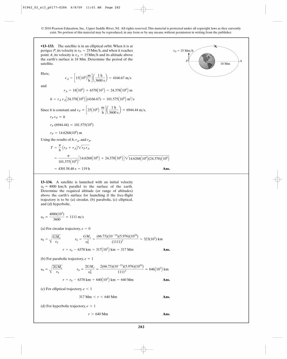
282
© 2010 Pearson Education, Inc., Upper Saddle River, NJ. All rights reserved. This material is protected under all copyright laws as they currentlyexist. No portion of this material may be reproduced, in any form or by any means, without permission in writing from the publisher.
•13–133. The satellite is in an elliptical orbit. When it is atperigee P, its velocity is , and when it reachespoint A, its velocity is and its altitude abovethe earth’s surface is 18 Mm. Determine the period of thesatellite.
vA = 15 Mm>hvP = 25 Mm>h
AP
vP � 25 Mm/h
18 Mm
Here,
and
Since h is constant and ,
Using the results of h, rA, and rP,
Ans. = 4301 58.48 s = 119 h
=
p
101.575 A109 BC14.6268 A106 B + 24.378 A106 B D214.6268 A106 B(24.378) A106 B
T =
p
6 ArP + rA B2rP rA
rP = 14.6268(106) m
rP (6944.44) = 101.575(109)
rP vP = h
vP = c25 A106 B mhd a
1 h3600 s
b = 6944.44 m>s
h = rA vA C24.378 A106 B D(4166.67) = 101.575 A109 B m2>s
rA = 18 A106 B + 6378 A103 B = 24.378 A106 B m
vA = c15 A106 Bmhd a
1 h3600 s
b = 4166.67 m>s
13–134. A satellite is launched with an initial velocityparallel to the surface of the earth.
Determine the required altitude (or range of altitudes)above the earth’s surface for launching if the free-flighttrajectory is to be (a) circular, (b) parabolic, (c) elliptical,and (d) hyperbolic.
v0 = 4000 km>h
(a) For circular trajectory,
Ans.
(b) For parabolic trajectory,
Ans.
(c) For elliptical trajectory,
Ans.
(d) For hyperbolic trajectory,
Ans.r 7 640 Mm
e 7 1
317 Mm 6 r 6 640 Mm
e 6 1
r = r0 - 6378 km = 640 A103 B km = 640 Mm
y0 =
A2GMe
r0 r0 =
2GMe
y20
=
2(66.73)(10- 12)(5.976)(1024)
11112 = 646 A103 B km
e = 1
r = r0 - 6378 km = 317 A103 B km = 317 Mm
y0 =
AGMe
r0 r0 =
GMe
y20
=
(66.73)(10- 12)(5.976)(1024)
(1111)2 = 323(103) km
e = 0
y0 =
4000(103)
3600= 1111 m>s
91962_02_s13_p0177-0284 6/8/09 11:01 AM Page 282
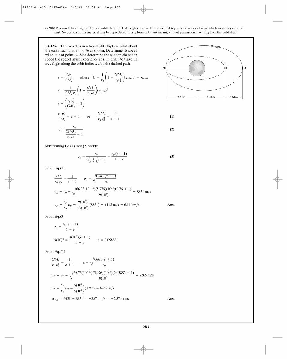
283
© 2010 Pearson Education, Inc., Upper Saddle River, NJ. All rights reserved. This material is protected under all copyright laws as they currentlyexist. No portion of this material may be reproduced, in any form or by any means, without permission in writing from the publisher.
13–135. The rocket is in a free-flight elliptical orbit aboutthe earth such that as shown. Determine its speedwhen it is at point A. Also determine the sudden change inspeed the rocket must experience at B in order to travel infree flight along the orbit indicated by the dashed path.
e = 0.76
9 Mm 8 Mm 5 Mm
ACB
(1)
(2)
Substituting Eq.(1) into (2) yields:
(3)
From Eq.(1),
Ans.
From Eq.(3),
From Eq. (1),
Ans.¢yB = 6458 - 8831 = -2374 m>s = -2.37 km>s
yB =
rp
ra yC =
8(106)
9(106) (7265) = 6458 m>s
yC = y0 =
B
66.73(10- 12)(5.976)(1024)(0.05882 + 1)
8(106)= 7265 m>s
GMe
r0 y20
=
1e + 1 y0 =
B
GMe (e + 1)
r0
9(10)6=
8(106)(e + 1)
1 - e e = 0.05882
ra =
r0 (e + 1)
1 - e
yA =
rp
ra yB =
9(106)
13(106) (8831) = 6113 m>s = 6.11 km>s
yB = y0 =
B
66.73(10- 12)(5.976)(1024)(0.76 + 1)
9(106)= 8831 m>s
GMe
r0 y20
=
1e + 1 y0 =
A
GMe (e + 1)
r0
ra =
r0
2 A 1e + 1 B - 1
=
r0 (e + 1)
1 - e
ra =
r0
2GMe
r0 y20
- 1
r0 y20
GMe= e + 1 or GMe
r0 y20
=
1e + 1
e = ¢ r0 y20
GMe- 1≤
e =
1GMe r0
¢1 -
GMe
r0 y20≤(r0 y0)
2
e =
Ch2
GMe where C =
1r0
¢1 -
GMe
r0y20≤ and h = r0 y0
91962_02_s13_p0177-0284 6/8/09 11:02 AM Page 283
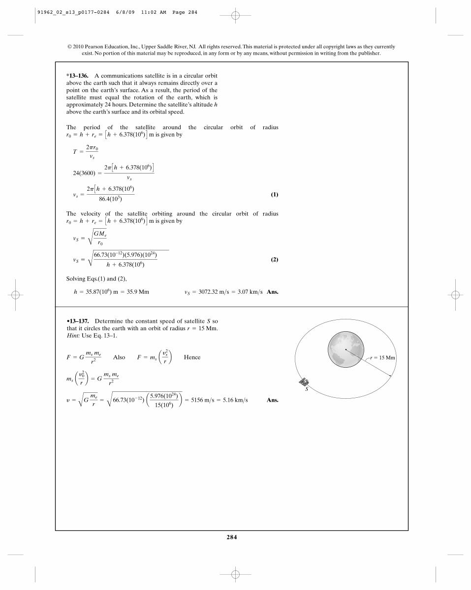
284
© 2010 Pearson Education, Inc., Upper Saddle River, NJ. All rights reserved. This material is protected under all copyright laws as they currentlyexist. No portion of this material may be reproduced, in any form or by any means, without permission in writing from the publisher.
*13–136. A communications satellite is in a circular orbitabove the earth such that it always remains directly over apoint on the earth’s surface. As a result, the period of thesatellite must equal the rotation of the earth, which isapproximately 24 hours. Determine the satellite’s altitude habove the earth’s surface and its orbital speed.
The period of the satellite around the circular orbit of radiusis given by
(1)
The velocity of the satellite orbiting around the circular orbit of radiusis given by
(2)
Solving Eqs.(1) and (2),
Ans.h = 35.87(106) m = 35.9 Mm vS = 3072.32 m>s = 3.07 km>s
vS =
C
66.73(10-12)(5.976)(1024)
h + 6.378(106)
vS =
CGMe
r0
r0 = h + re = Ch + 6.378(106) D m
vs =
2p Ch + 6.378(106)
86.4(103)
24(3600) =
2p Ch + 6.378(106) D
vs
T =
2pr0
vs
r0 = h + re = Ch + 6.378(106) D m
•13–137. Determine the constant speed of satellite S sothat it circles the earth with an orbit of radius .Hint: Use Eq. 13–1.
r = 15 Mm
Ans.y =
AG
me
r=
B66.73(10- 12) a
5.976(1024)
15(106)b = 5156 m>s = 5.16 km>s
ms ay2
0
rb = G
ms me
r2
F = G ms me
r2 Also F = ms ay2
s
rb Hence
S
r � 15 Mm
91962_02_s13_p0177-0284 6/8/09 11:02 AM Page 284