Embed Size (px)
Citation preview
8. BENDING AND FORMING OPERATIONS
8.1. STRESS, STRAIN, ELONGATION, COMPRESSION
The process of material forming (i.e., deformation ) depends on several laws,closely related to those of physics. First of all, the law of constant volumeapplies here. No matter how much we shrink or stretch a part, no matter howmuch we form it, draw it, or compress it, the basic volume we had at thebeginning will always be there. True, minor volumnar changes may takeplace during compressive forming, but these are so minute, so small withregard to the bulk of the part that they can easily be considered irrelevant.
Another rule is pertaining to the distribution of particles in formed material.During changes of material structure, all affected segments will attempt torelocate into areas of least resistance. In other words, the material willalways tend to flow where it is not obstructed, or to fill the gaps locatednearby, or to conform to shapes exerting pressure upon it.
Rule number three: Every permanent deformation takes place after thechanges in the material structure exceeded the maximum elastic limit of thatmaterial. However, this is not the final deformation achieved, as, after releaseof the applied forming pressure, the material makes an attempt to return toits previous location; we say it springs back. The complete amount ofdeformation is therefore equal to the sum of the elastic segment and theplastic segment of the operation, or
(8-1)
BENDING AND FORMING OPERATIONS
There are two types of deformation that can be observed during any formingprocess. These can be either localized, or affecting the whole part:
Equal deformation, which is fairly even, free from excessive deviation fromits mean values, and unaffected by axial orientation.
Unequal deformation, where the shape and the size of the formed part arechanged unequally. Here the differences between mean values andmarginal values of the process are of greater span. During this type ofdeformation, many additional stresses, beneficial or detrimental, maydevelop.
The emergence of localized stresses within the material during unequaldeformation is caused mainly by
Unequal friction between the forming tool and the part
Unequal temperature distribution within the part
Too complex a product
Chemical differences within the material
Mechanical properties of the material
These stresses sometimes equal each other out, for which reason they arenot always observable on the surface of the part. Anyway, the human eye ismostly capable of observing only volumnar changes; those occurring on thestructural or substructural level, taking place between the crystals ofmaterial, are not visible to us.
The deformative processes applied to the fabricated sheet-metal material canbe numerous and their sources can be easily grouped into but severalcategories:
Cutting
Simple bending
Forming
Drawing
Compressive forming
Combinations of the above
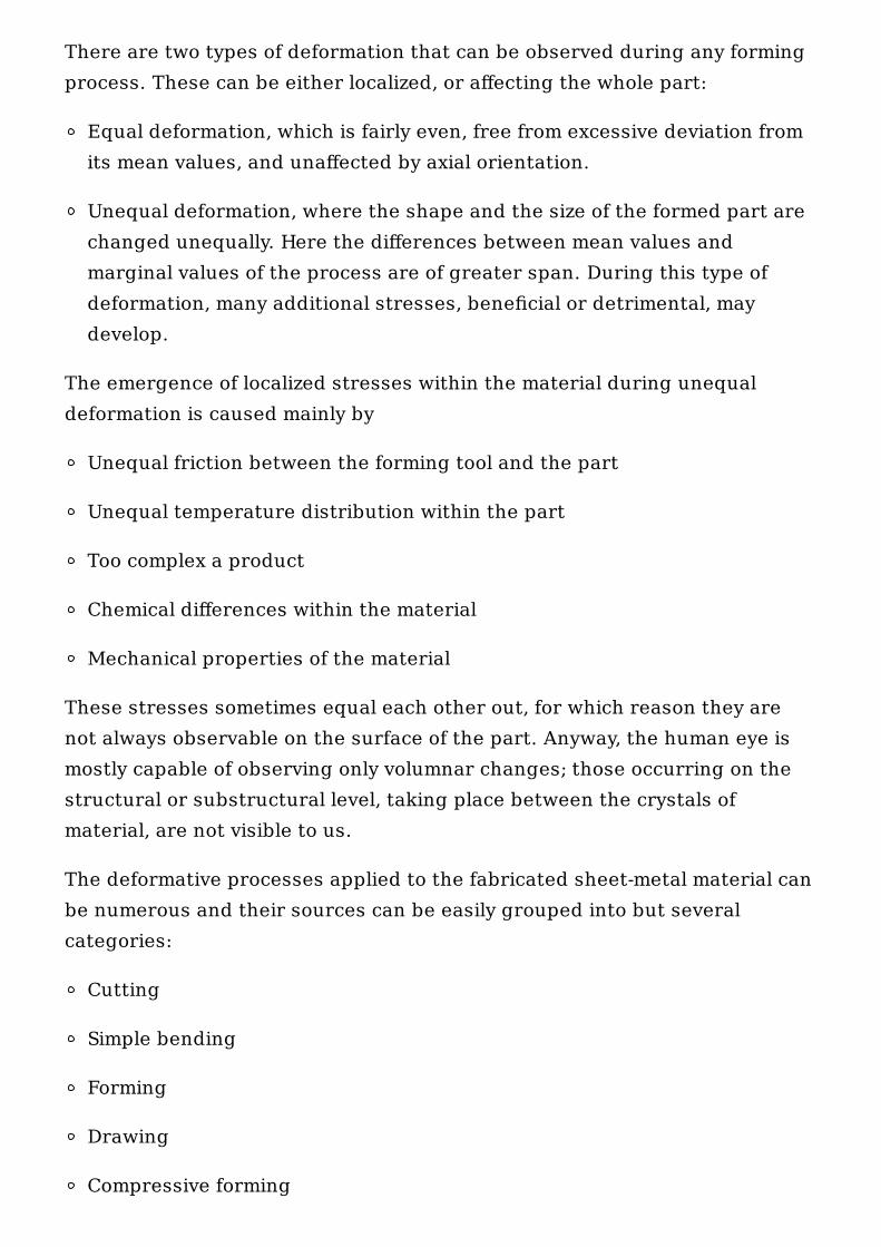
Bending and forming are quite similar operations, the only difference beingthe presence of the drawing action in forming. In simple bending, a portionof the part is flexed along a straight line until a bend is obtained. In forming,the bend line may be curved, circular, or otherwise shaped. The variability ofthe bend line contour causes the material to expand on one side and becompressed on the opposite.
For these reasons, there are basically two types of forming operations, oneproducing shrink flanges and the other is used for making stretch flanges. Inshrink flanges, as the name implies, the material of a flange is squeezed orcompressed during forming, whereas stretch flanges are stretched andsubsequently thinned (Fig. 8-1).
The evaluation of the flange type should be pursued by observing the flatlayout of a part, which clearly shows where the material for each flange isgoing to be taken from and how it will be adapted.
Bending, even though generally considered a draw-free process, doescontain some minute amounts of drawing action as well. Drawing-typemovement of material can be found along the circumference of the bend,where a small amount of stretching and shrinking can be seen. Some mayconsider this to be a lengthwise shift of various material layers with respect
Figure 8-1. Types of flanges.
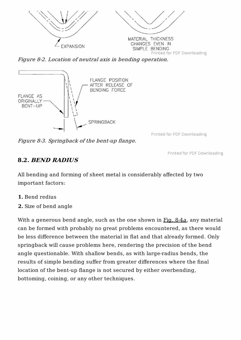
to each other, but the expansion or contraction of material attributable to itschange in linear length with subsequent change in thickness (see Fig. 8-2) iscertainly a minute amount of drawing action. True, it is an occurrence sogreatly limited in scope that we may perhaps consider it negligible.
The inside portion of the bend usually does not display any considerablechanges because its outline is restricted by the contact with tooling.
The cross-section of the bend and flange, in order to be considered a resultof the bending operation, must maintain the same thickness as the rest ofthe sheet out of which it was made. An ideal situation can be found wherespring-hard sheet-metal material, which—bent freely, preferably by hand,without the use of any bend-enforcing tools—forms an extremely shallowradius, returning to its original shape immediately on cessation of theapplied force.
With softer metals, the tendency to succumb to the bending force is greater,and these materials do not always return to their original form and shape.The amount of spring-back, or back-returning force within the metal, is lesserin such ductile materials, making them easily altered by the application offorce.
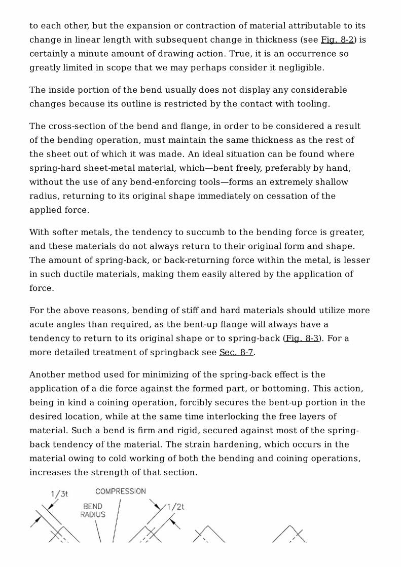
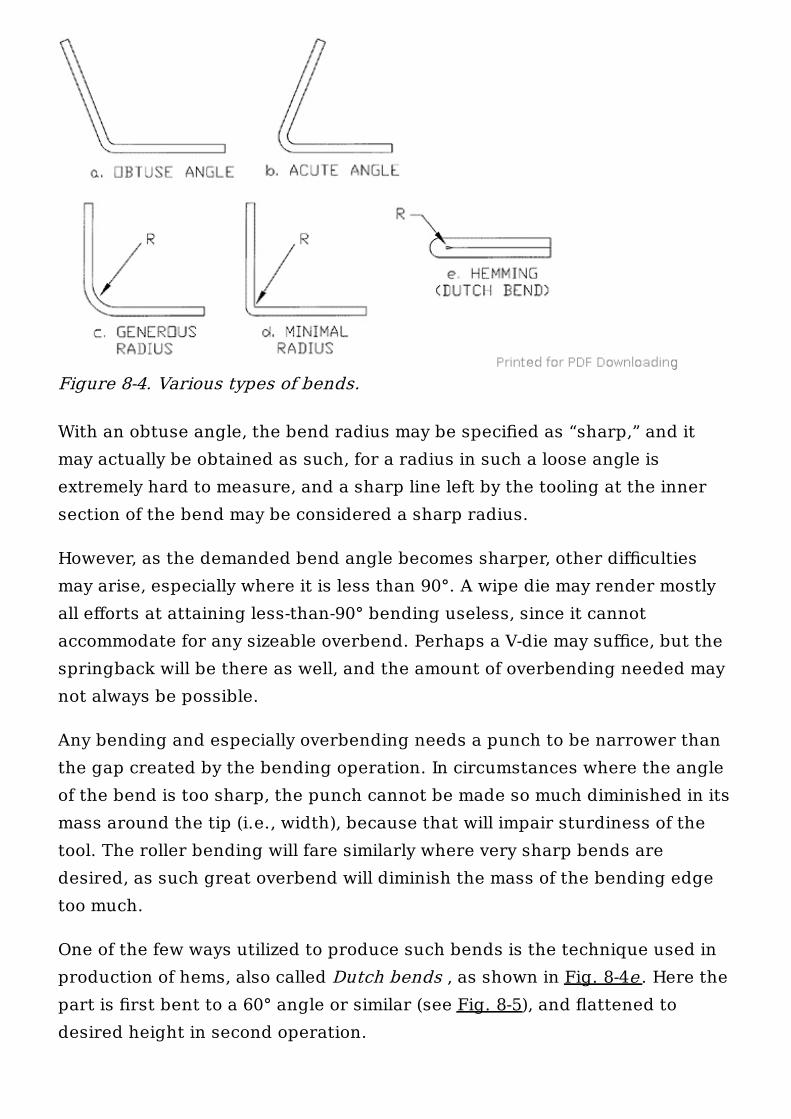
For the above reasons, bending of stiff and hard materials should utilize moreacute angles than required, as the bent-up flange will always have atendency to return to its original shape or to spring-back (Fig. 8-3). For amore detailed treatment of springback see Sec. 8-7.
Another method used for minimizing of the spring-back effect is theapplication of a die force against the formed part, or bottoming. This action,being in kind a coining operation, forcibly secures the bent-up portion in thedesired location, while at the same time interlocking the free layers ofmaterial. Such a bend is firm and rigid, secured against most of the spring-back tendency of the material. The strain hardening, which occurs in thematerial owing to cold working of both the bending and coining operations,increases the strength of that section.
8.2. BEND RADIUS
All bending and forming of sheet metal is considerably affected by twoimportant factors:
1. Bend redius2. Size of bend angle
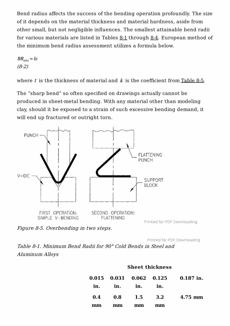
With a generous bend angle, such as the one shown in Fig. 8-4a , any materialcan be formed with probably no great problems encountered, as there wouldbe less difference between the material in flat and that already formed. Onlyspringback will cause problems here, rendering the precision of the bendangle questionable. With shallow bends, as with large-radius bends, theresults of simple bending suffer from greater differences where the finallocation of the bent-up flange is not secured by either overbending,bottoming, coining, or any other techniques.
Figure 8-2. Location of neutral axis in bending operation.
Figure 8-3. Springback of the bent-up flange.
With an obtuse angle, the bend radius may be specified as “sharp,” and itmay actually be obtained as such, for a radius in such a loose angle isextremely hard to measure, and a sharp line left by the tooling at the innersection of the bend may be considered a sharp radius.
However, as the demanded bend angle becomes sharper, other difficultiesmay arise, especially where it is less than 90°. A wipe die may render mostlyall efforts at attaining less-than-90° bending useless, since it cannotaccommodate for any sizeable overbend. Perhaps a V-die may suffice, but thespringback will be there as well, and the amount of overbending needed maynot always be possible.
Any bending and especially overbending needs a punch to be narrower thanthe gap created by the bending operation. In circumstances where the angleof the bend is too sharp, the punch cannot be made so much diminished in itsmass around the tip (i.e., width), because that will impair sturdiness of thetool. The roller bending will fare similarly where very sharp bends aredesired, as such great overbend will diminish the mass of the bending edgetoo much.
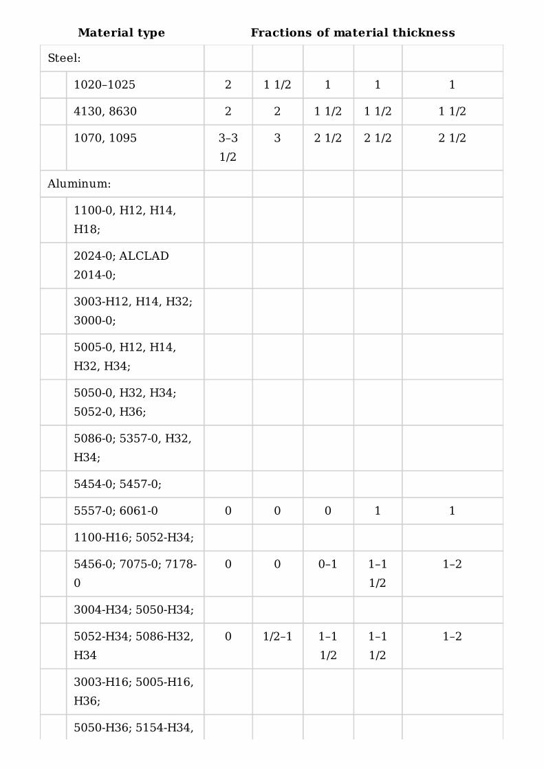
One of the few ways utilized to produce such bends is the technique used inproduction of hems, also called Dutch bends , as shown in Fig. 8-4e . Here thepart is first bent to a 60° angle or similar (see Fig. 8-5), and flattened todesired height in second operation.
Figure 8-4. Various types of bends.
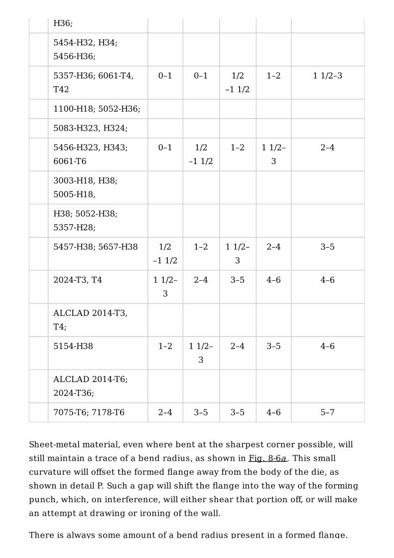
Bend radius affects the success of the bending operation profoundly. The sizeof it depends on the material thickness and material hardness, aside fromother small, but not negligible influences. The smallest attainable bend radiifor various materials are listed in Tables 8-1 through 8-4. European method ofthe minimum bend radius assessment utilizes a formula below.
(8-2)
where t is the thickness of material and k is the coefficient from Table 8-5.
The “sharp bend” so often specified on drawings actually cannot beproduced in sheet-metal bending. With any material other than modelingclay, should it be exposed to a strain of such excessive bending demand, itwill end up fractured or outright torn.
Table 8-1. Minimum Bend Radii for 90° Cold Bends in Steel andAluminum Alloys
Figure 8-5. Overbending in two steps.
Sheet thickness
0.015in.
0.031in.
0.062in.
0.125in.
0.187 in.
0.4mm
0.8mm
1.5mm
3.2mm
4.75 mm
Material type Fractions of material thickness
Steel:
1020–1025 2 1 1/2 1 1 1
4130, 8630 2 2 1 1/2 1 1/2 1 1/2
1070, 1095 3–31/2
3 2 1/2 2 1/2 2 1/2
Aluminum:
1100-0, H12, H14,H18;
2024-0; ALCLAD2014-0;
3003-H12, H14, H32;3000-0;
5005-0, H12, H14,H32, H34;
5050-0, H32, H34;5052-0, H36;
5086-0; 5357-0, H32,H34;
5454-0; 5457-0;
5557-0; 6061-0 0 0 0 1 1
1100-H16; 5052-H34;
5456-0; 7075-0; 7178-0
0 0 0–1 1–11/2
1–2
3004-H34; 5050-H34;
5052-H34; 5086-H32,H34
0 1/2–1 1–11/2
1–11/2
1–2
3003-H16; 5005-H16,H36;
5050-H36; 5154-H34,
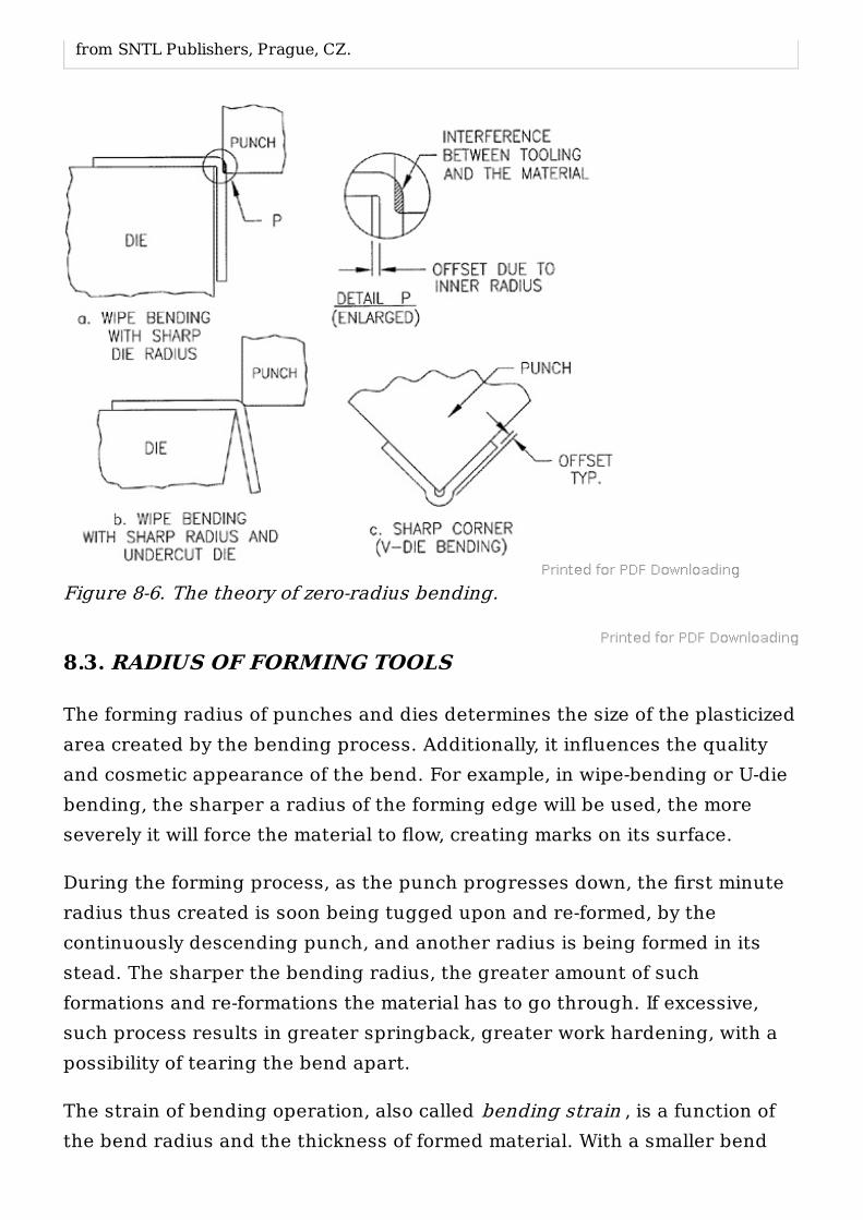
Sheet-metal material, even where bent at the sharpest corner possible, willstill maintain a trace of a bend radius, as shown in Fig. 8-6a . This smallcurvature will offset the formed flange away from the body of the die, asshown in detail P. Such a gap will shift the flange into the way of the formingpunch, which, on interference, will either shear that portion off, or will makean attempt at drawing or ironing of the wall.
There is always some amount of a bend radius present in a formed flange.
H36;
5454-H32, H34;5456-H36;
5357-H36; 6061-T4,T42
0–1 0–1 1/2–1 1/2
1–2 1 1/2–3
1100-H18; 5052-H36;
5083-H323, H324;
5456-H323, H343;6061-T6
0–1 1/2–1 1/2
1–2 1 1/2–3
2–4
3003-H18, H38;5005-H18,
H38; 5052-H38;5357-H28;
5457-H38; 5657-H38 1/2–1 1/2
1–2 1 1/2–3
2–4 3–5
2024-T3, T4 1 1/2–3
2–4 3–5 4–6 4–6
ALCLAD 2014-T3,T4;
5154-H38 1–2 1 1/2–3
2–4 3–5 4–6
ALCLAD 2014-T6;2024-T36;
7075-T6; 7178-T6 2–4 3–5 3–5 4–6 5–7
There is always some amount of a bend radius present in a formed flange.Even a 180° bend, such as a hem (also called a Dutch bend ), shown in Fig. 8-4e , will contain a slight bend radius, unless completely flattened out by acoining operation, to the point of cracking.
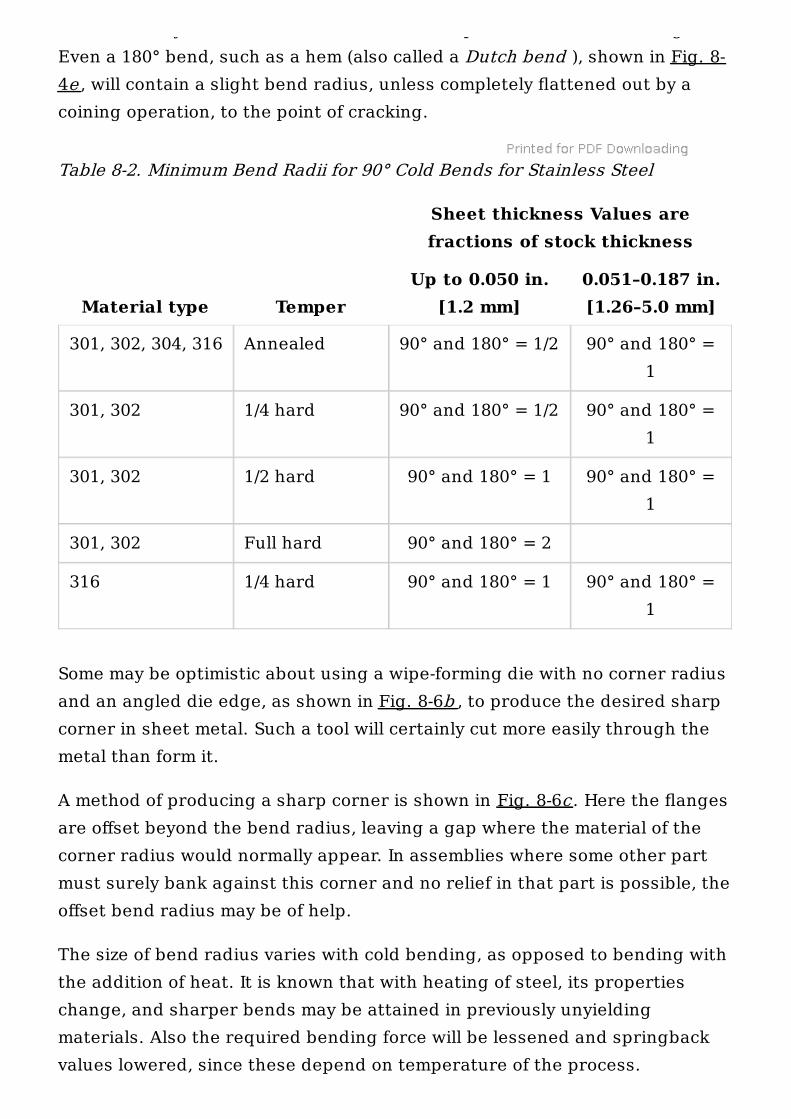
Table 8-2. Minimum Bend Radii for 90° Cold Bends for Stainless Steel
Some may be optimistic about using a wipe-forming die with no corner radiusand an angled die edge, as shown in Fig. 8-6b , to produce the desired sharpcorner in sheet metal. Such a tool will certainly cut more easily through themetal than form it.
A method of producing a sharp corner is shown in Fig. 8-6c . Here the flangesare offset beyond the bend radius, leaving a gap where the material of thecorner radius would normally appear. In assemblies where some other partmust surely bank against this corner and no relief in that part is possible, theoffset bend radius may be of help.
The size of bend radius varies with cold bending, as opposed to bending withthe addition of heat. It is known that with heating of steel, its propertieschange, and sharper bends may be attained in previously unyieldingmaterials. Also the required bending force will be lessened and springbackvalues lowered, since these depend on temperature of the process.
Sheet thickness Values arefractions of stock thickness
Material type TemperUp to 0.050 in.
[1.2 mm]0.051–0.187 in.[1.26–5.0 mm]
301, 302, 304, 316 Annealed 90° and 180° = 1/2 90° and 180° =1
301, 302 1/4 hard 90° and 180° = 1/2 90° and 180° =1
301, 302 1/2 hard 90° and 180° = 1 90° and 180° =1
301, 302 Full hard 90° and 180° = 2
316 1/4 hard 90° and 180° = 1 90° and 180° =1
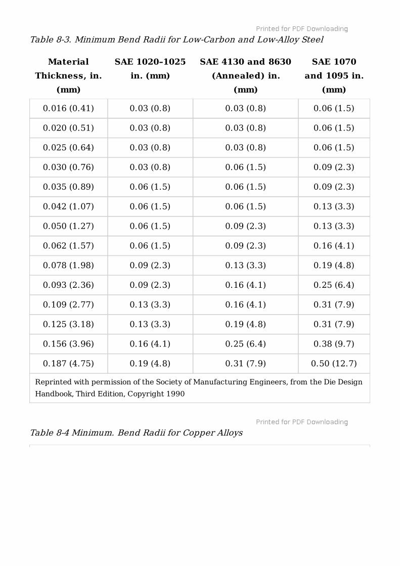
Table 8-3. Minimum Bend Radii for Low-Carbon and Low-Alloy Steel
Table 8-4 Minimum. Bend Radii for Copper Alloys
MaterialThickness, in.
(mm)
SAE 1020–1025in. (mm)
SAE 4130 and 8630(Annealed) in.
(mm)
SAE 1070and 1095 in.
(mm)
Reprinted with permission of the Society of Manufacturing Engineers, from the Die DesignHandbook, Third Edition, Copyright 1990
0.016 (0.41) 0.03 (0.8) 0.03 (0.8) 0.06 (1.5)
0.020 (0.51) 0.03 (0.8) 0.03 (0.8) 0.06 (1.5)
0.025 (0.64) 0.03 (0.8) 0.03 (0.8) 0.06 (1.5)
0.030 (0.76) 0.03 (0.8) 0.06 (1.5) 0.09 (2.3)
0.035 (0.89) 0.06 (1.5) 0.06 (1.5) 0.09 (2.3)
0.042 (1.07) 0.06 (1.5) 0.06 (1.5) 0.13 (3.3)
0.050 (1.27) 0.06 (1.5) 0.09 (2.3) 0.13 (3.3)
0.062 (1.57) 0.06 (1.5) 0.09 (2.3) 0.16 (4.1)
0.078 (1.98) 0.09 (2.3) 0.13 (3.3) 0.19 (4.8)
0.093 (2.36) 0.09 (2.3) 0.16 (4.1) 0.25 (6.4)
0.109 (2.77) 0.13 (3.3) 0.16 (4.1) 0.31 (7.9)
0.125 (3.18) 0.13 (3.3) 0.19 (4.8) 0.31 (7.9)
0.156 (3.96) 0.16 (4.1) 0.25 (6.4) 0.38 (9.7)
0.187 (4.75) 0.19 (4.8) 0.31 (7.9) 0.50 (12.7)
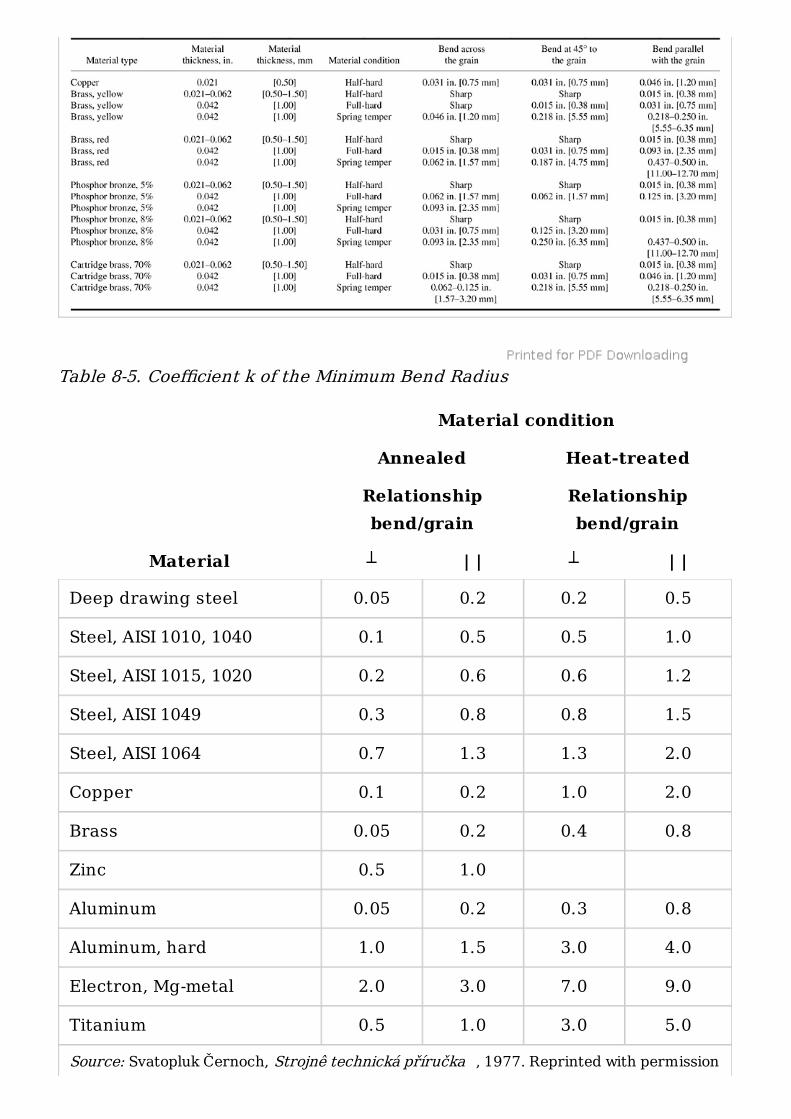
Table 8-5. Coefficient k of the Minimum Bend Radius
Material condition
Annealed Heat-treated
Relationshipbend/grain
Relationshipbend/grain
Material ┴ | | ┴ | |
Source: Svatopluk Černoch, Strojnê technická příručka , 1977. Reprinted with permission
Deep drawing steel 0.05 0.2 0.2 0.5
Steel, AISI 1010, 1040 0.1 0.5 0.5 1.0
Steel, AISI 1015, 1020 0.2 0.6 0.6 1.2
Steel, AISI 1049 0.3 0.8 0.8 1.5
Steel, AISI 1064 0.7 1.3 1.3 2.0
Copper 0.1 0.2 1.0 2.0
Brass 0.05 0.2 0.4 0.8
Zinc 0.5 1.0
Aluminum 0.05 0.2 0.3 0.8
Aluminum, hard 1.0 1.5 3.0 4.0
Electron, Mg-metal 2.0 3.0 7.0 9.0
Titanium 0.5 1.0 3.0 5.0
8.3. RADIUS OF FORMING TOOLS
The forming radius of punches and dies determines the size of the plasticizedarea created by the bending process. Additionally, it influences the qualityand cosmetic appearance of the bend. For example, in wipe-bending or U-diebending, the sharper a radius of the forming edge will be used, the moreseverely it will force the material to flow, creating marks on its surface.
During the forming process, as the punch progresses down, the first minuteradius thus created is soon being tugged upon and re-formed, by thecontinuously descending punch, and another radius is being formed in itsstead. The sharper the bending radius, the greater amount of suchformations and re-formations the material has to go through. If excessive,such process results in greater springback, greater work hardening, with apossibility of tearing the bend apart.
The strain of bending operation, also called bending strain , is a function ofthe bend radius and the thickness of formed material. With a smaller bend
from SNTL Publishers, Prague, CZ.
Figure 8-6. The theory of zero-radius bending.
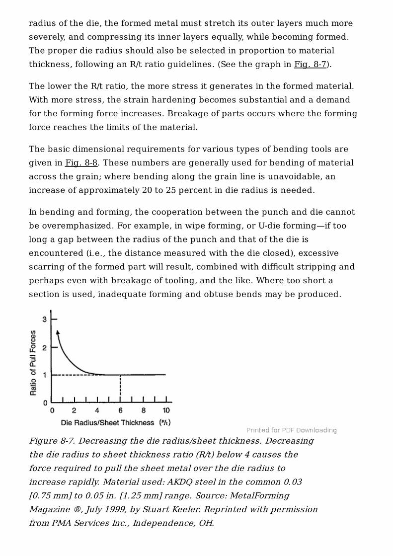
radius of the die, the formed metal must stretch its outer layers much moreseverely, and compressing its inner layers equally, while becoming formed.The proper die radius should also be selected in proportion to materialthickness, following an R/t ratio guidelines. (See the graph in Fig. 8-7).
The lower the R/t ratio, the more stress it generates in the formed material.With more stress, the strain hardening becomes substantial and a demandfor the forming force increases. Breakage of parts occurs where the formingforce reaches the limits of the material.
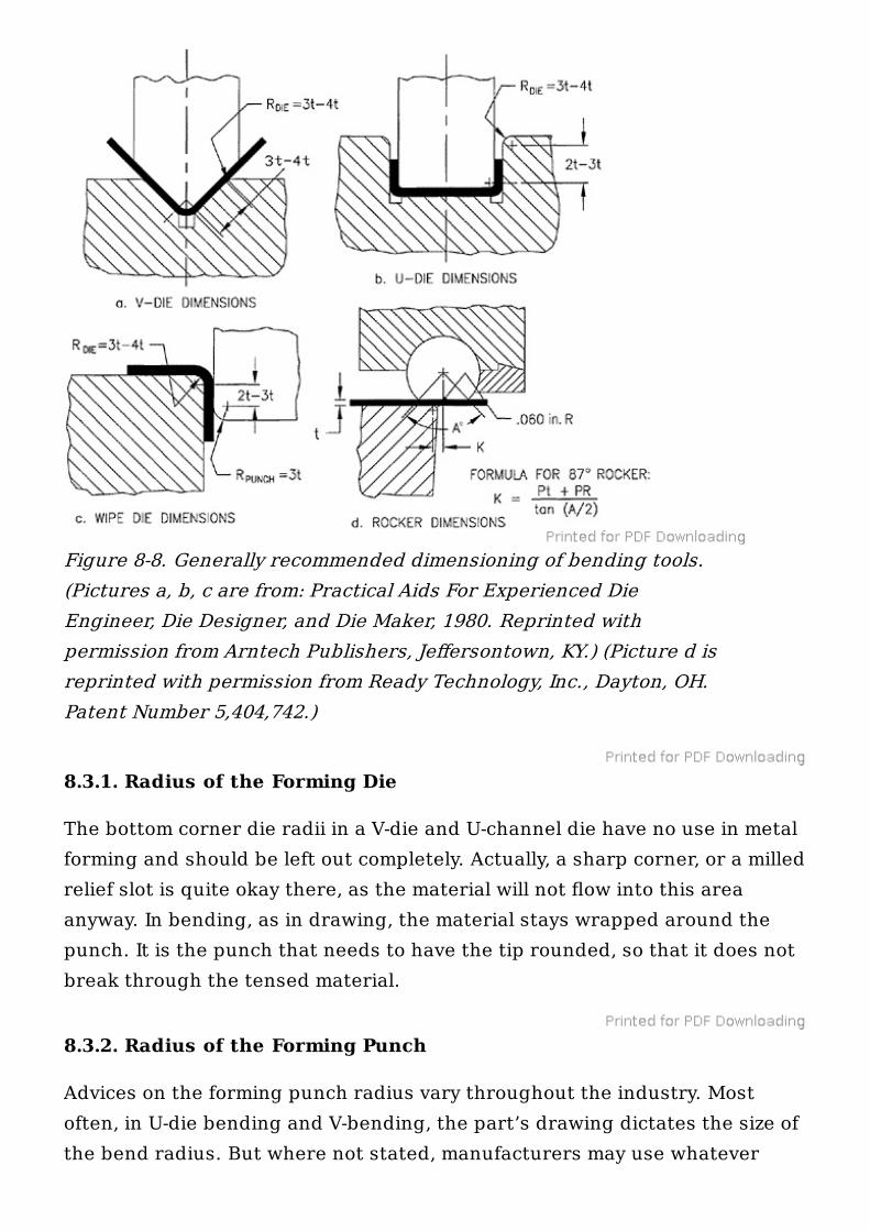
The basic dimensional requirements for various types of bending tools aregiven in Fig. 8-8. These numbers are generally used for bending of materialacross the grain; where bending along the grain line is unavoidable, anincrease of approximately 20 to 25 percent in die radius is needed.
In bending and forming, the cooperation between the punch and die cannotbe overemphasized. For example, in wipe forming, or U-die forming—if toolong a gap between the radius of the punch and that of the die isencountered (i.e., the distance measured with the die closed), excessivescarring of the formed part will result, combined with difficult stripping andperhaps even with breakage of tooling, and the like. Where too short asection is used, inadequate forming and obtuse bends may be produced.
Figure 8-7. Decreasing the die radius/sheet thickness. Decreasingthe die radius to sheet thickness ratio (R/t) below 4 causes theforce required to pull the sheet metal over the die radius toincrease rapidly. Material used: AKDQ steel in the common 0.03[0.75 mm] to 0.05 in. [1.25 mm] range. Source: MetalFormingMagazine ®, July 1999, by Stuart Keeler. Reprinted with permissionfrom PMA Services Inc., Independence, OH.
8.3.1. Radius of the Forming Die
The bottom corner die radii in a V-die and U-channel die have no use in metalforming and should be left out completely. Actually, a sharp corner, or a milledrelief slot is quite okay there, as the material will not flow into this areaanyway. In bending, as in drawing, the material stays wrapped around thepunch. It is the punch that needs to have the tip rounded, so that it does notbreak through the tensed material.
8.3.2. Radius of the Forming Punch
Advices on the forming punch radius vary throughout the industry. Mostoften, in U-die bending and V-bending, the part’s drawing dictates the size ofthe bend radius. But where not stated, manufacturers may use whatever
Figure 8-8. Generally recommended dimensioning of bending tools.(Pictures a, b, c are from: Practical Aids For Experienced DieEngineer, Die Designer, and Die Maker, 1980. Reprinted withpermission from Arntech Publishers, Jeffersontown, KY.) (Picture d isreprinted with permission from Ready Technology, Inc., Dayton, OH.Patent Number 5,404,742.)
suits them the best. Some recommend to have the tip of the forming punchradiused to the tune of t to 1.5t , where t is the material thickness.Elsewhere, especially in sheet-metal fabricating field, a habit of bendingeverything with R 0.031 in. [0.75 mm] to R 0.062 in. [1.50 mm] prevails.Perhaps this is due to the fact that press brakes used for such bending runusually at a much slower rate than most progressive dies. However, where a1/8 in. [3.25 mm] thick material will be bent with 0.5t radius tooling, thetensile strain of the upper layers of the formed material will increaseconsiderably and breakages may occur in many such cases.
Along with general dimensioning rules for different types of bending tools,the recommended radius range of the wipe forming punch is given in Fig. 8-8c . This type of a punch is subject to similar rules like those pertaining to thebending radius of the die.
8.3.3. Gap Between the Forming Punch and Die
The space between forming punch and die exerts yet another significantinfluence on the result of bending operation. As such, it is also a subject tomany advices, which vary in scope from the material thickness’ width of agap, or t spacing, up to 1.2t and perhaps even more. Others recommend thisdistance to be 0.002–0.005 in. [0.05–0.13 mm] smaller than the maximum limitof the fabricated material thickness, including its tolerance range.
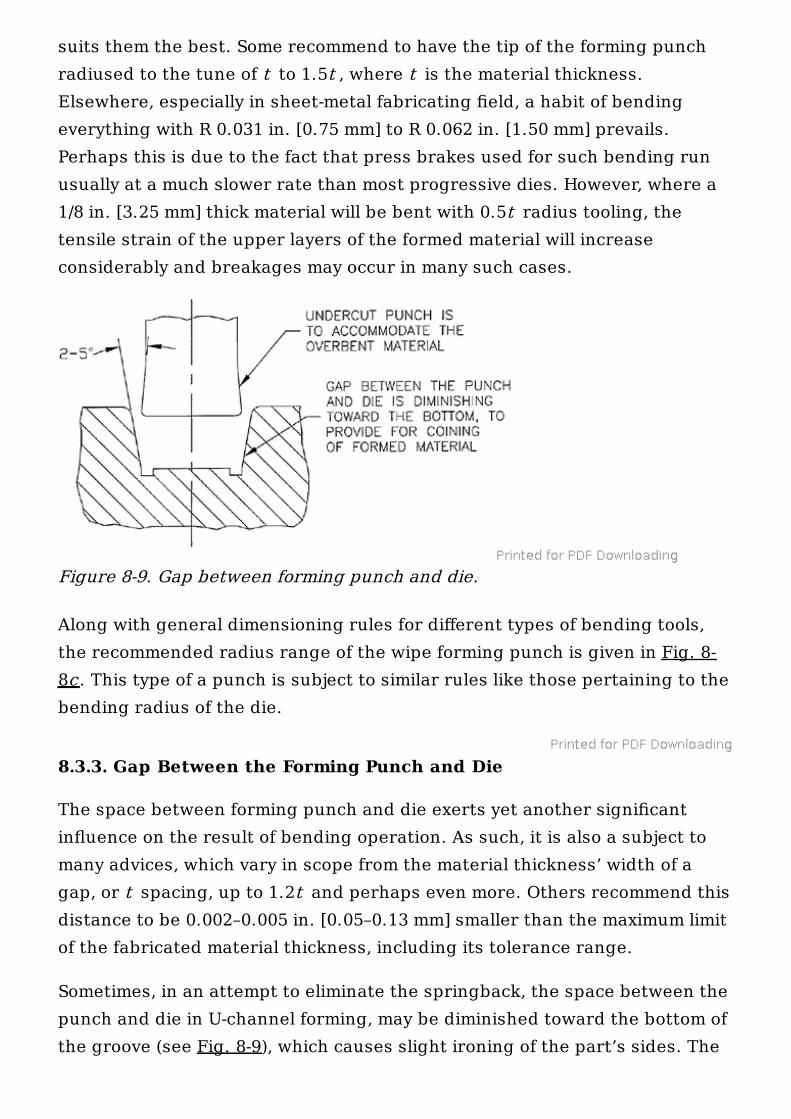
Sometimes, in an attempt to eliminate the springback, the space between thepunch and die in U-channel forming, may be diminished toward the bottom ofthe groove (see Fig. 8-9), which causes slight ironing of the part’s sides. The
Figure 8-9. Gap between forming punch and die.
ironed material is misplaced in the direction of the upper portion of theflange (i.e., leg), forcing it to lean toward the punch. The punch is purposelyrelieved to accommodate for such a movement. The misplaced materialbecomes solidified on cessation of ironing and it allows for lesser springback,often turning out parts at exactly 90°.
8.3.4. The Speed of Forming Operation
Surely, the forming speed affects the forming process too, even thoughmostly in a negative way. For with increase of the forming speed, the speed-generated heat due to forming rises as well, and greater material hardeningin steel can be observed. In some aluminum alloys an exact opposite may takeplace.
8.4. EDGE FORMABILITY
The edge formability is the ability of material to be formed withoutfracturing or thinning around the edges of holes. This characteristic isexperimentally assessed by stretching a circular blank containing a roundhole in the middle. The stretching is done by the punch with a flat bottom,and the edge of the centrally located opening is observed for the appearanceof cracks.
Interestingly enough, it was noticed that with the equally dispersed punchpressure, the hole does not remain round. With hot-rolled low-carbon steelused for drawing, the largest opening size was found at a 45° angle off thegrain line. In cold-rolled steel of the drawing type, the largest diameter wasfound at the location parallel with the grain direction or at 0° off the grainline, whereas in cold-rolled high-strength low-alloy steels the smallestdiameter could be found at 90° off the grain line.
Edge formability is going to be increasingly important owing to the escalateduse of high-strength steel. This is because such a mechanical property of thematerial is crucial in evaluation of sheet-metal behavior in forming andbending operations.
Edge cracking in bending originates already in blanking or punchingoperations, and it is often present with other kinds of material separatingprocesses, such as trimming, perforating, or cutoff. The appearance of cracks
is closely related to the shear of sheet-metal material in cutting, where thestretched stock is separated via connecting action of the cracks, one set ofwhich originates on top of the material thickness (by the edge of a punch)and the other set comes up from the bottom (from the die edge) as shown inFig. 6-2. Varying the punch-die tolerance range may sometimes be helpful,but it cannot always be counted upon. Sometimes, only careful studies andtryout runs can show if the edge will crack in subsequent bending or not.
Surprisingly, laser-cutting is not always a culprit blamable for edge cracking,even though a laser cut can produce some localized damage in the areawhere it enters the cutting path, or around some curves and sharp corners.Whenever a laser path is drastically diverted in any direction, the influenceof the laser beam is increased proportionally to its deceleration, which isnecessary for its change of path.
One way to solve the problems with edge formability and edge cracking is byproducing all bends and doing all the forming first, and leaving the blankingoperation to the absolute end. Unfortunately, most of the time this approachcannot be utilized.
Often, the speed of the forming process can increase the cracks’ emergenceby heating the material to higher temperatures during faster speeds. Wherethis is the case, an evaluation of severity of forming operation should beattempted and the results calculated using the formula below:
(8-3)
where S = strain of forming (severity of forming), in percents t = thickness of material, initial t = thickness of material, final
Varying the press speed and varying the type of lubricant can sometimesbring about an improvement.
8.5. NEUTRAL AXIS IN BENDING
The neutral axis of the material is supposed to do exactly what its nameimplies: to remain neutral during the bending process and to conform to
F
i
f
neither side of the altered material.
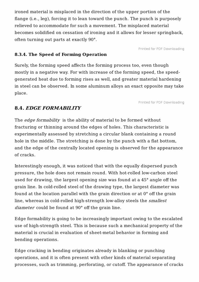
However, the neutral axis does not remain totally neutral, as it shifts slightlyin the forming operation, even though its length remains the same (Fig. 8-10).Because of the deformation of the bent-up material, the neutral axis movestoward the center of the bend radius.
This shift, even though small in size, may be of importance in some areas ofthe industry, for which reason it is included in the following chart. Its amountis based on the ratio of the bend radius and material thickness:
where v is the change in the neutral axis location in inches, which is directedtoward the origin of the bend radius.
For purposes of calculation of the flat size of a part, the location of neutralaxis, presented here as an ingredient of various formulas and tables, hasbeen altered with each type of bending operation performed. Thesepercentile values are based on actual tests and years of experience oftoolmakers, designers, and engineers.
8.6. TYPES OF BENDING OPERATIONS
Bending of sheet metal can be accomplished through utilization of severalmanufacturing processes. First of all, the distinction can be made as far asthe bending part’s support is concerned: There is supported bending andunsupported bending.
Figure 8-10. Shift of the neutral axis in bending.
R/t 0.1 0.25 0.5 1.0 2.0 3.0 4.0 6.0 10.0
v 0.0125 0.0135 0.015 0.0165 0.0175 0.018 0.0185 0.019 0.019
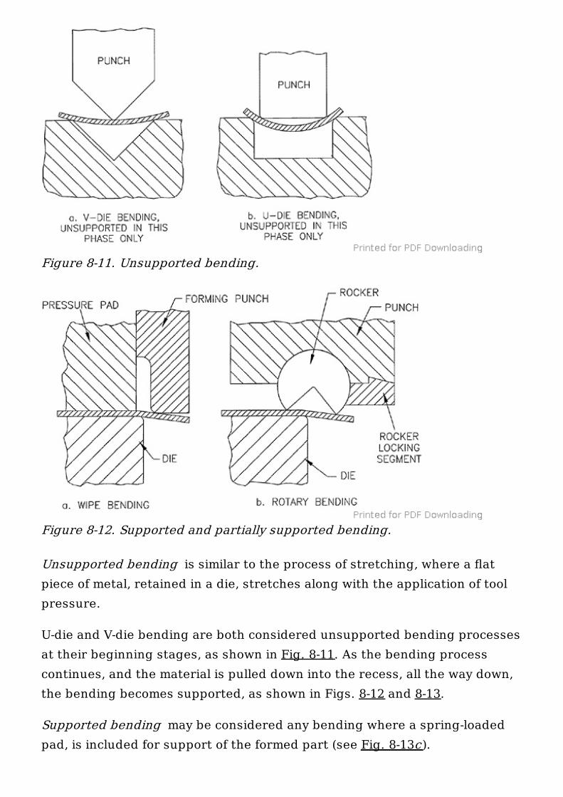
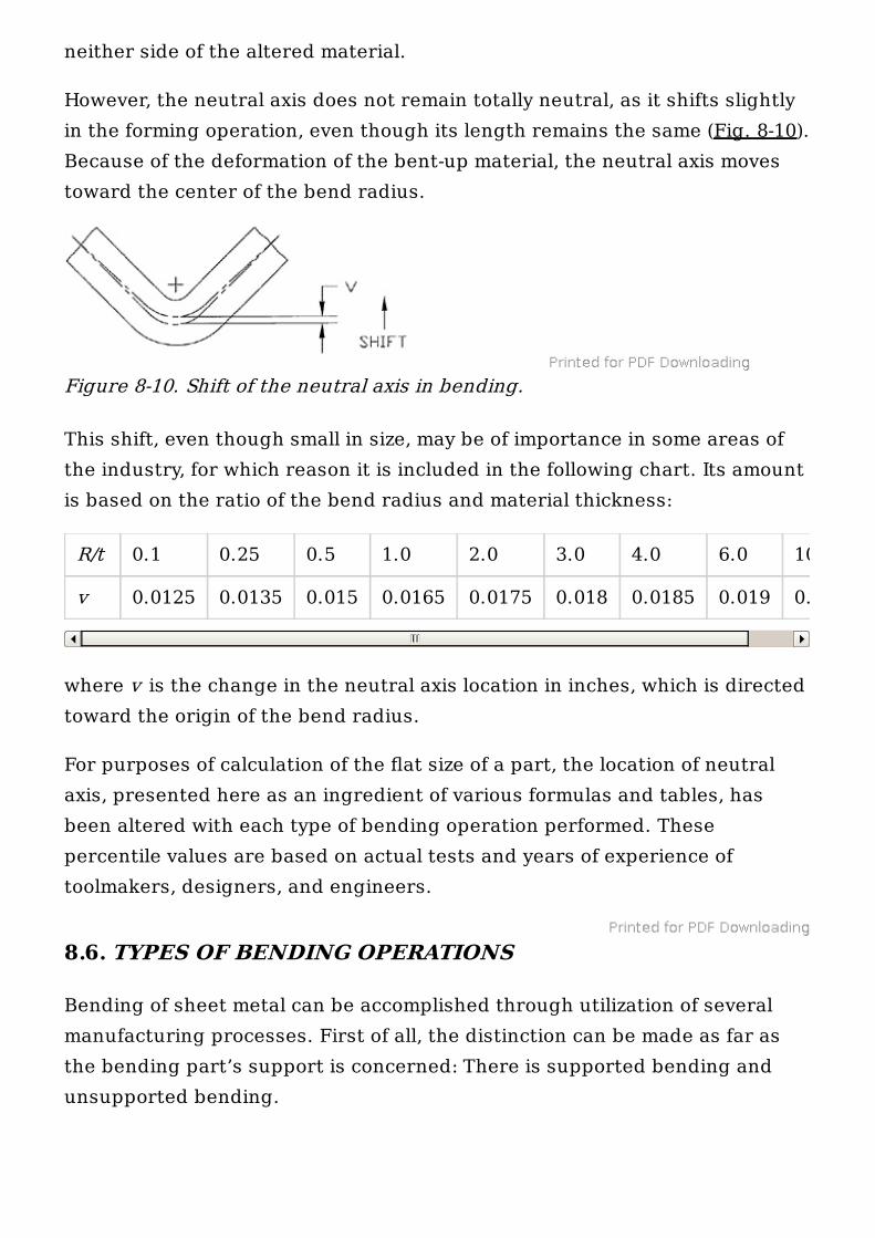
Unsupported bending is similar to the process of stretching, where a flatpiece of metal, retained in a die, stretches along with the application of toolpressure.
U-die and V-die bending are both considered unsupported bending processesat their beginning stages, as shown in Fig. 8-11. As the bending processcontinues, and the material is pulled down into the recess, all the way down,the bending becomes supported, as shown in Figs. 8-12 and 8-13.
Supported bending may be considered any bending where a spring-loadedpad, is included for support of the formed part (see Fig. 8-13c).
Figure 8-11. Unsupported bending.
Figure 8-12. Supported and partially supported bending.
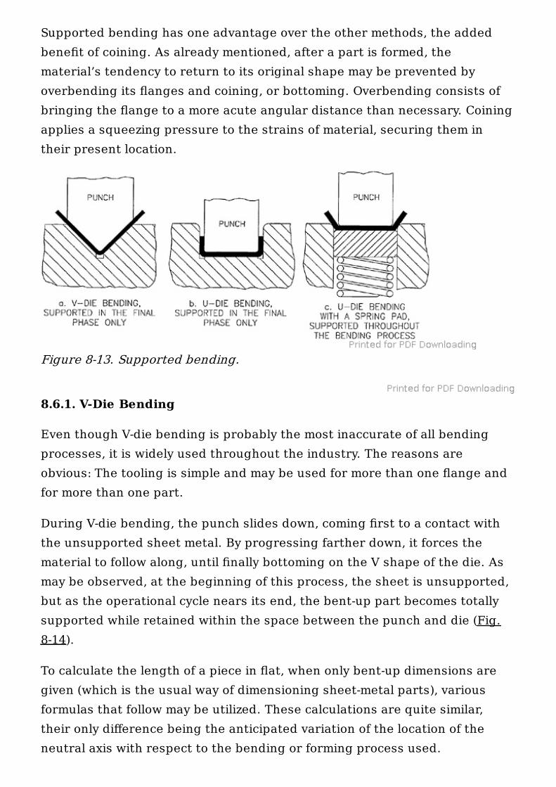
Supported bending has one advantage over the other methods, the addedbenefit of coining. As already mentioned, after a part is formed, thematerial’s tendency to return to its original shape may be prevented byoverbending its flanges and coining, or bottoming. Overbending consists ofbringing the flange to a more acute angular distance than necessary. Coiningapplies a squeezing pressure to the strains of material, securing them intheir present location.
8.6.1. V-Die Bending
Even though V-die bending is probably the most inaccurate of all bendingprocesses, it is widely used throughout the industry. The reasons areobvious: The tooling is simple and may be used for more than one flange andfor more than one part.
During V-die bending, the punch slides down, coming first to a contact withthe unsupported sheet metal. By progressing farther down, it forces thematerial to follow along, until finally bottoming on the V shape of the die. Asmay be observed, at the beginning of this process, the sheet is unsupported,but as the operational cycle nears its end, the bent-up part becomes totallysupported while retained within the space between the punch and die (Fig.8-14).
To calculate the length of a piece in flat, when only bent-up dimensions aregiven (which is the usual way of dimensioning sheet-metal parts), variousformulas that follow may be utilized. These calculations are quite similar,their only difference being the anticipated variation of the location of theneutral axis with respect to the bending or forming process used.
Figure 8-13. Supported bending.
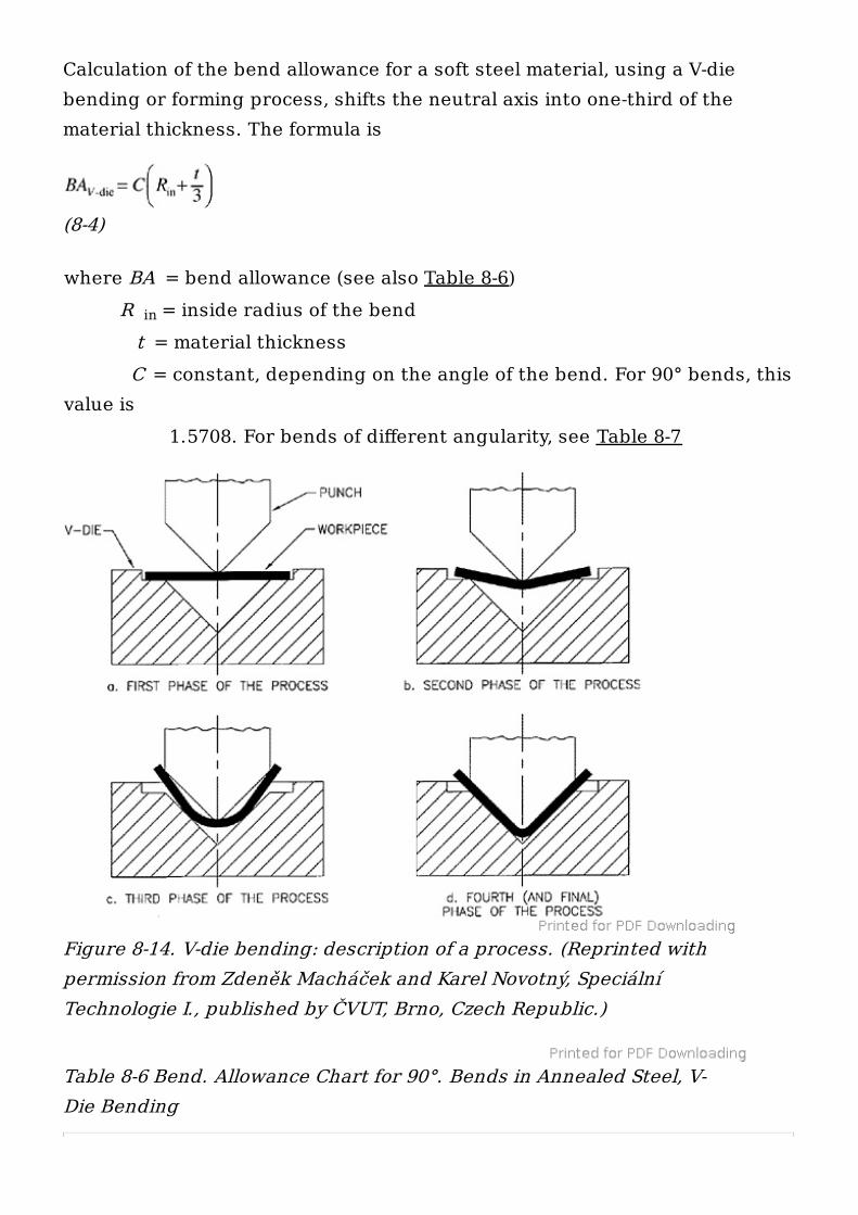
Calculation of the bend allowance for a soft steel material, using a V-diebending or forming process, shifts the neutral axis into one-third of thematerial thickness. The formula is
(8-4)
where BA = bend allowance (see also Table 8-6) R = inside radius of the bend t = material thickness C = constant, depending on the angle of the bend. For 90° bends, thisvalue is 1.5708. For bends of different angularity, see Table 8-7
Table 8-6 Bend. Allowance Chart for 90°. Bends in Annealed Steel, V-Die Bending
in
Figure 8-14. V-die bending: description of a process. (Reprinted withpermission from Zdeněk Macháček and Karel Novotný, SpeciálníTechnologie I., published by ČVUT, Brno, Czech Republic.)
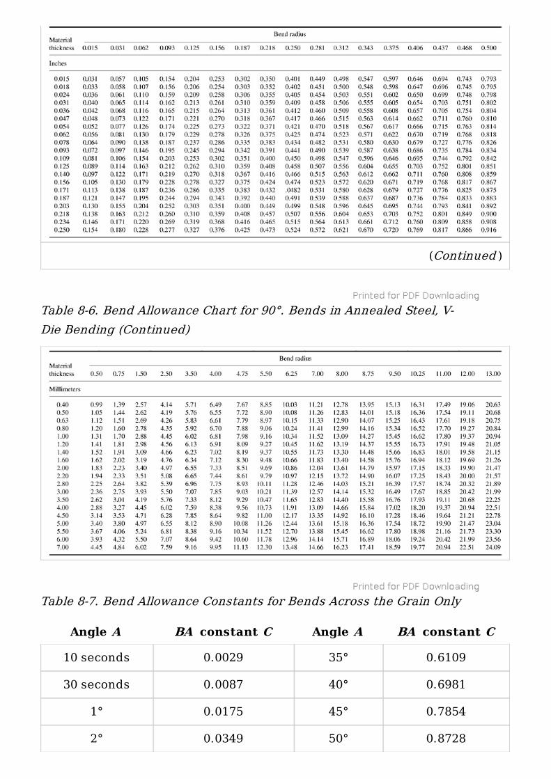
Table 8-6. Bend Allowance Chart for 90°. Bends in Annealed Steel, V-Die Bending (Continued)
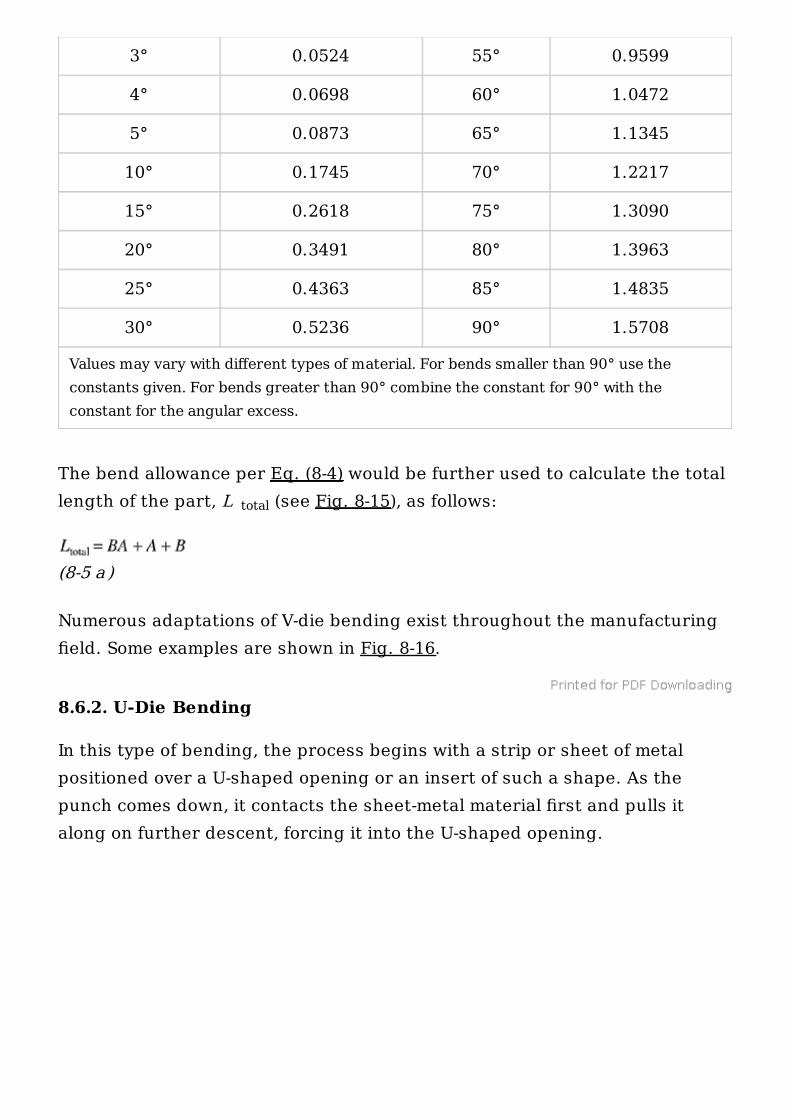
Table 8-7. Bend Allowance Constants for Bends Across the Grain Only
(Continued )
Angle A BA constant C Angle A BA constant C
10 seconds 0.0029 35° 0.6109
30 seconds 0.0087 40° 0.6981
1° 0.0175 45° 0.7854
2° 0.0349 50° 0.8728
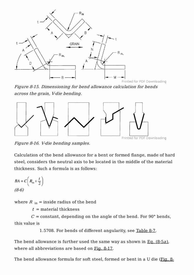
The bend allowance per Eq. (8-4) would be further used to calculate the totallength of the part, L (see Fig. 8-15), as follows:
(8-5 a )
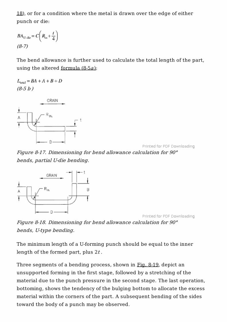
Numerous adaptations of V-die bending exist throughout the manufacturingfield. Some examples are shown in Fig. 8-16.
8.6.2. U-Die Bending
In this type of bending, the process begins with a strip or sheet of metalpositioned over a U-shaped opening or an insert of such a shape. As thepunch comes down, it contacts the sheet-metal material first and pulls italong on further descent, forcing it into the U-shaped opening.
Values may vary with different types of material. For bends smaller than 90° use theconstants given. For bends greater than 90° combine the constant for 90° with theconstant for the angular excess.
3° 0.0524 55° 0.9599
4° 0.0698 60° 1.0472
5° 0.0873 65° 1.1345
10° 0.1745 70° 1.2217
15° 0.2618 75° 1.3090
20° 0.3491 80° 1.3963
25° 0.4363 85° 1.4835
30° 0.5236 90° 1.5708
total
Calculation of the bend allowance for a bent or formed flange, made of hardsteel, considers the neutral axis to be located in the middle of the materialthickness. Such a formula is as follows:
(8-6)
where R = inside radius of the bend t = material thickness C = constant, depending on the angle of the bend. For 90° bends,this value is 1.5708. For bends of different angularity, see Table 8-7.
The bend allowance is further used the same way as shown in Eq. (8-5a ),where all abbreviations are based on Fig. 8-17.
The bend allowance formula for soft steel, formed or bent in a U die (Fig. 8-
Figure 8-15. Dimensioning for bend allowance calculation for bendsacross the grain, V-die bending.
Figure 8-16. V-die bending samples.
in
18), or for a condition where the metal is drawn over the edge of eitherpunch or die:
(8-7)
The bend allowance is further used to calculate the total length of the part,using the altered formula (8-5a ):
(8-5 b )
The minimum length of a U-forming punch should be equal to the innerlength of the formed part, plus 2t .
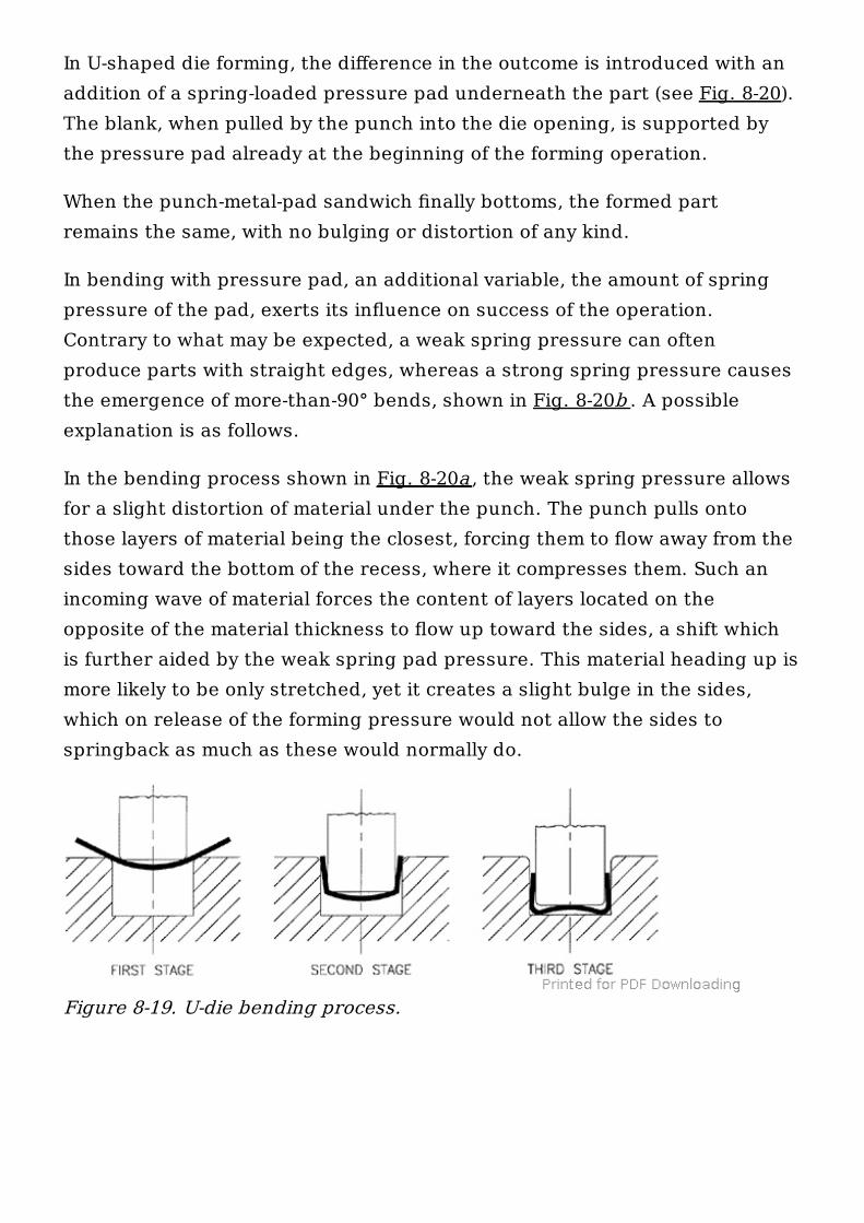
Three segments of a bending process, shown in Fig. 8-19, depict anunsupported forming in the first stage, followed by a stretching of thematerial due to the punch pressure in the second stage. The last operation,bottoming, shows the tendency of the bulging bottom to allocate the excessmaterial within the corners of the part. A subsequent bending of the sidestoward the body of a punch may be observed.
Figure 8-17. Dimensioning for bend allowance calculation for 90°bends, partial U-die bending.
Figure 8-18. Dimensioning for bend allowance calculation for 90°bends, U-type bending.
In U-shaped die forming, the difference in the outcome is introduced with anaddition of a spring-loaded pressure pad underneath the part (see Fig. 8-20).The blank, when pulled by the punch into the die opening, is supported bythe pressure pad already at the beginning of the forming operation.
When the punch-metal-pad sandwich finally bottoms, the formed partremains the same, with no bulging or distortion of any kind.
In bending with pressure pad, an additional variable, the amount of springpressure of the pad, exerts its influence on success of the operation.Contrary to what may be expected, a weak spring pressure can oftenproduce parts with straight edges, whereas a strong spring pressure causesthe emergence of more-than-90° bends, shown in Fig. 8-20b . A possibleexplanation is as follows.
In the bending process shown in Fig. 8-20a , the weak spring pressure allowsfor a slight distortion of material under the punch. The punch pulls ontothose layers of material being the closest, forcing them to flow away from thesides toward the bottom of the recess, where it compresses them. Such anincoming wave of material forces the content of layers located on theopposite of the material thickness to flow up toward the sides, a shift whichis further aided by the weak spring pad pressure. This material heading up ismore likely to be only stretched, yet it creates a slight bulge in the sides,which on release of the forming pressure would not allow the sides tospringback as much as these would normally do.
Figure 8-19. U-die bending process.
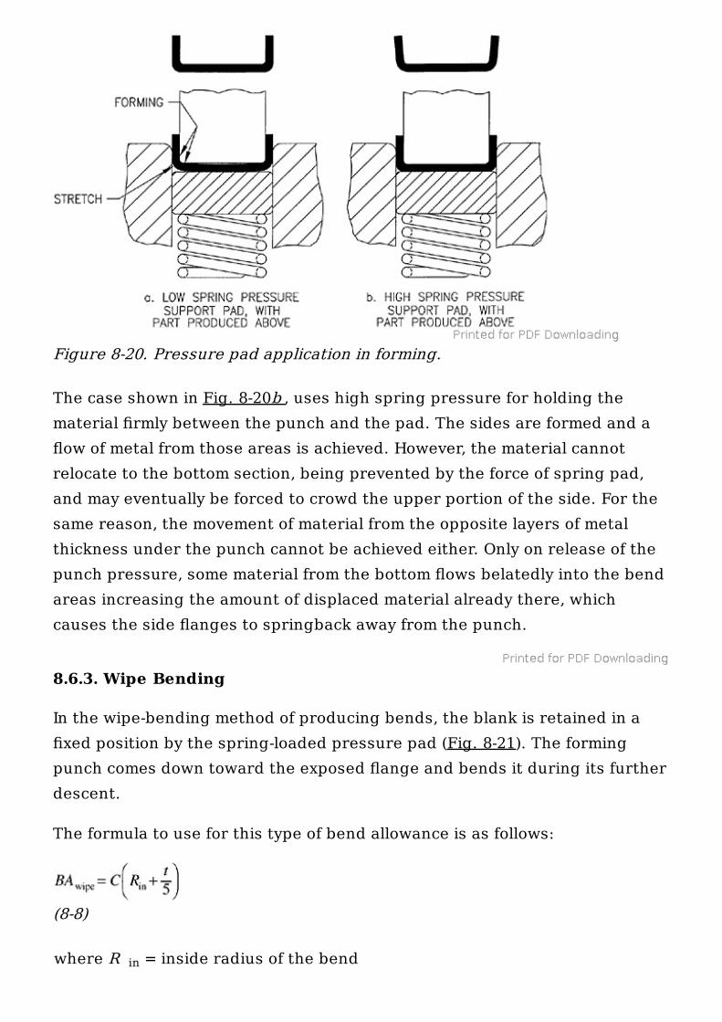
The case shown in Fig. 8-20b , uses high spring pressure for holding thematerial firmly between the punch and the pad. The sides are formed and aflow of metal from those areas is achieved. However, the material cannotrelocate to the bottom section, being prevented by the force of spring pad,and may eventually be forced to crowd the upper portion of the side. For thesame reason, the movement of material from the opposite layers of metalthickness under the punch cannot be achieved either. Only on release of thepunch pressure, some material from the bottom flows belatedly into the bendareas increasing the amount of displaced material already there, whichcauses the side flanges to springback away from the punch.
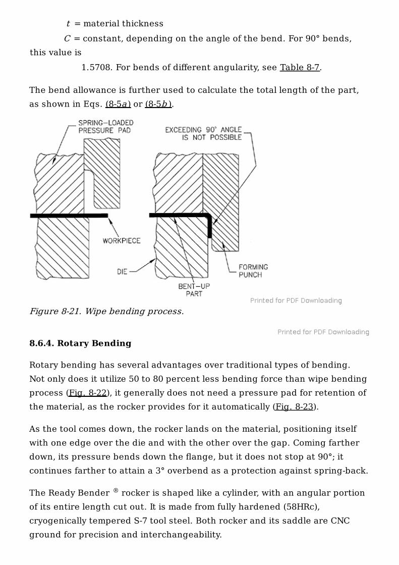
8.6.3. Wipe Bending
In the wipe-bending method of producing bends, the blank is retained in afixed position by the spring-loaded pressure pad (Fig. 8-21). The formingpunch comes down toward the exposed flange and bends it during its furtherdescent.
The formula to use for this type of bend allowance is as follows:
(8-8)
where R = inside radius of the bend
Figure 8-20. Pressure pad application in forming.
in
t = material thickness C = constant, depending on the angle of the bend. For 90° bends,this value is 1.5708. For bends of different angularity, see Table 8-7.
The bend allowance is further used to calculate the total length of the part,as shown in Eqs. (8-5a ) or (8-5b ).
8.6.4. Rotary Bending
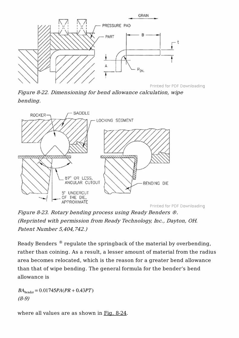
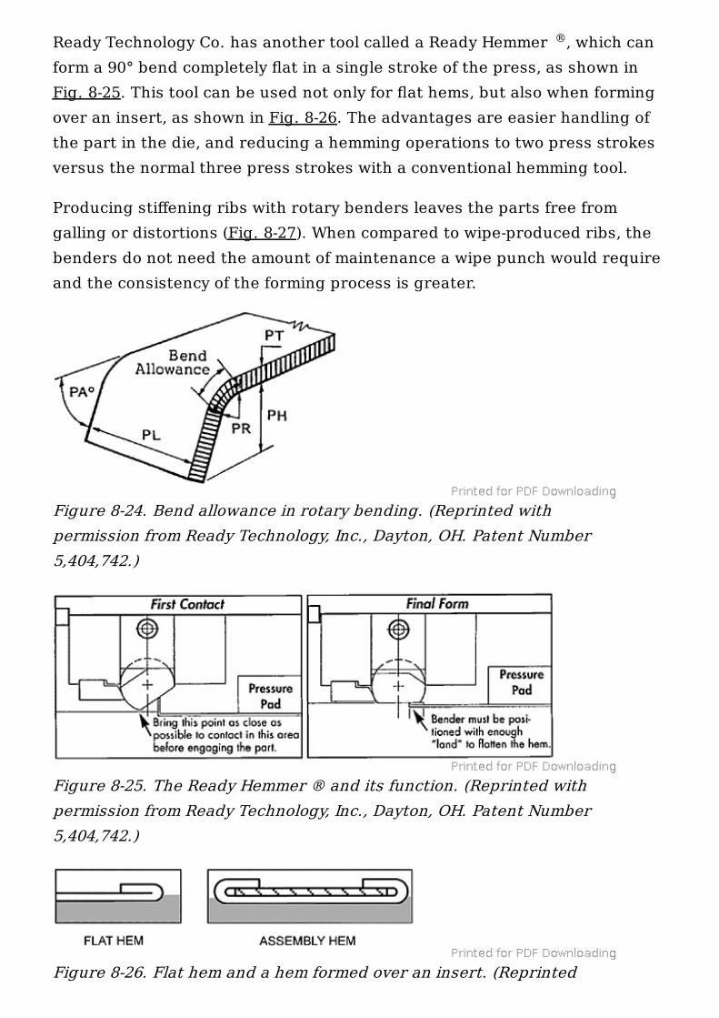
Rotary bending has several advantages over traditional types of bending.Not only does it utilize 50 to 80 percent less bending force than wipe bendingprocess (Fig. 8-22), it generally does not need a pressure pad for retention ofthe material, as the rocker provides for it automatically (Fig. 8-23).
As the tool comes down, the rocker lands on the material, positioning itselfwith one edge over the die and with the other over the gap. Coming fartherdown, its pressure bends down the flange, but it does not stop at 90°; itcontinues farther to attain a 3° overbend as a protection against spring-back.
The Ready Bender rocker is shaped like a cylinder, with an angular portionof its entire length cut out. It is made from fully hardened (58HRc),cryogenically tempered S-7 tool steel. Both rocker and its saddle are CNCground for precision and interchangeability.
Figure 8-21. Wipe bending process.
®
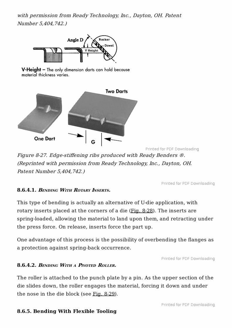
Ready Benders regulate the springback of the material by overbending,rather than coining. As a result, a lesser amount of material from the radiusarea becomes relocated, which is the reason for a greater bend allowancethan that of wipe bending. The general formula for the bender’s bendallowance is
(8-9)
where all values are as shown in Fig. 8-24.
Figure 8-22. Dimensioning for bend allowance calculation, wipebending.
Figure 8-23. Rotary bending process using Ready Benders ®.(Reprinted with permission from Ready Technology, Inc., Dayton, OH.Patent Number 5,404,742.)
®
®
Ready Technology Co. has another tool called a Ready Hemmer , which canform a 90° bend completely flat in a single stroke of the press, as shown inFig. 8-25. This tool can be used not only for flat hems, but also when formingover an insert, as shown in Fig. 8-26. The advantages are easier handling ofthe part in the die, and reducing a hemming operations to two press strokesversus the normal three press strokes with a conventional hemming tool.
Producing stiffening ribs with rotary benders leaves the parts free fromgalling or distortions (Fig. 8-27). When compared to wipe-produced ribs, thebenders do not need the amount of maintenance a wipe punch would requireand the consistency of the forming process is greater.
®
Figure 8-24. Bend allowance in rotary bending. (Reprinted withpermission from Ready Technology, Inc., Dayton, OH. Patent Number5,404,742.)
Figure 8-25. The Ready Hemmer ® and its function. (Reprinted withpermission from Ready Technology, Inc., Dayton, OH. Patent Number5,404,742.)
Figure 8-26. Flat hem and a hem formed over an insert. (Reprinted
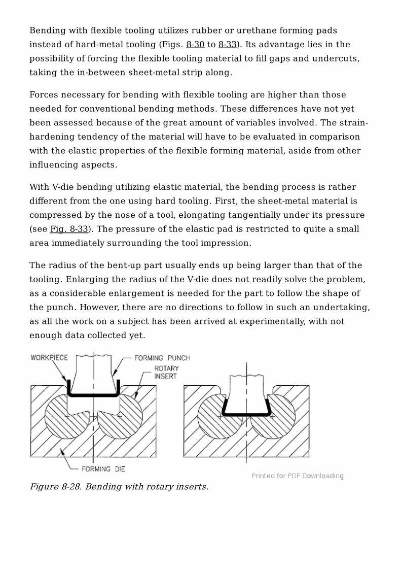
8.6.4.1. BENDING WITH ROTARY INSERTS.
This type of bending is actually an alternative of U-die application, withrotary inserts placed at the corners of a die (Fig. 8-28). The inserts arespring-loaded, allowing the material to land upon them, and retracting underthe press force. On release, inserts force the part up.
One advantage of this process is the possibility of overbending the flanges asa protection against spring-back occurrence.
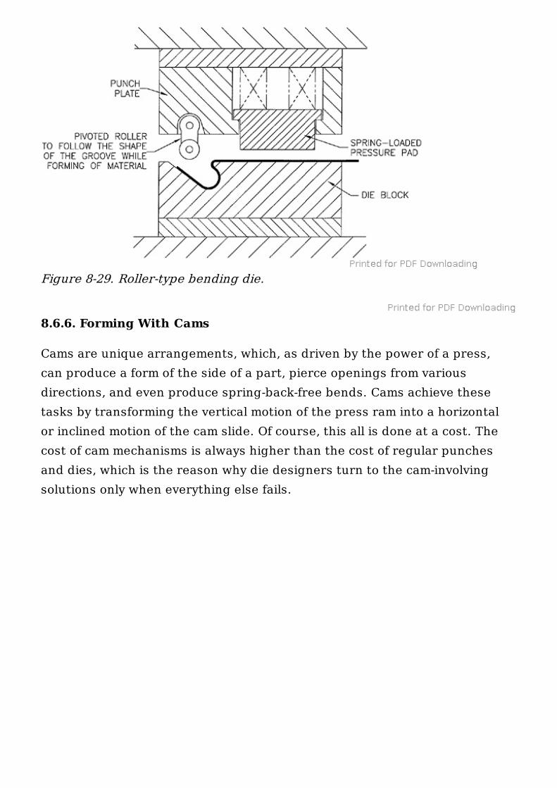
8.6.4.2. BENDING WITH A PIVOTED ROLLER.
The roller is attached to the punch plate by a pin. As the upper section of thedie slides down, the roller engages the material, forcing it down and underthe nose in the die block (see Fig. 8-29).
8.6.5. Bending With Flexible Tooling
with permission from Ready Technology, Inc., Dayton, OH. PatentNumber 5,404,742.)
Figure 8-27. Edge-stiffening ribs produced with Ready Benders ®.(Reprinted with permission from Ready Technology, Inc., Dayton, OH.Patent Number 5,404,742.)
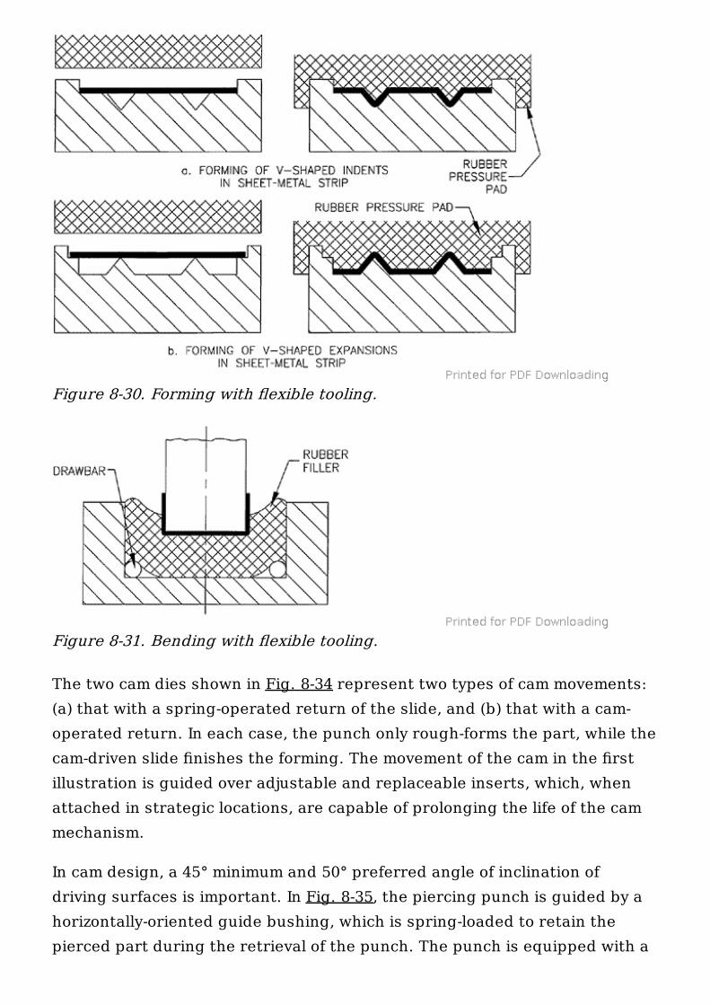
Bending with flexible tooling utilizes rubber or urethane forming padsinstead of hard-metal tooling (Figs. 8-30 to 8-33). Its advantage lies in thepossibility of forcing the flexible tooling material to fill gaps and undercuts,taking the in-between sheet-metal strip along.
Forces necessary for bending with flexible tooling are higher than thoseneeded for conventional bending methods. These differences have not yetbeen assessed because of the great amount of variables involved. The strain-hardening tendency of the material will have to be evaluated in comparisonwith the elastic properties of the flexible forming material, aside from otherinfluencing aspects.
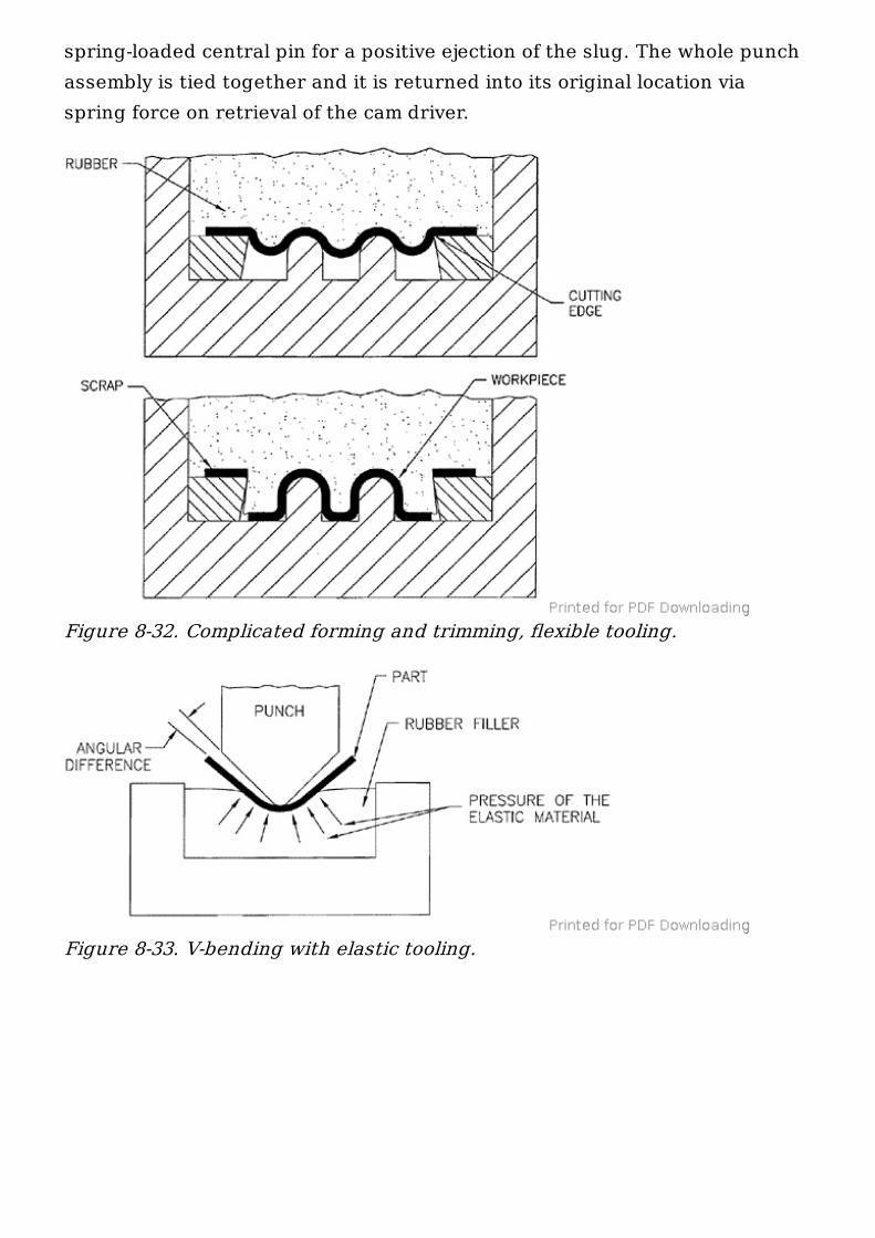
With V-die bending utilizing elastic material, the bending process is ratherdifferent from the one using hard tooling. First, the sheet-metal material iscompressed by the nose of a tool, elongating tangentially under its pressure(see Fig. 8-33). The pressure of the elastic pad is restricted to quite a smallarea immediately surrounding the tool impression.
The radius of the bent-up part usually ends up being larger than that of thetooling. Enlarging the radius of the V-die does not readily solve the problem,as a considerable enlargement is needed for the part to follow the shape ofthe punch. However, there are no directions to follow in such an undertaking,as all the work on a subject has been arrived at experimentally, with notenough data collected yet.
Figure 8-28. Bending with rotary inserts.
8.6.6. Forming With Cams
Cams are unique arrangements, which, as driven by the power of a press,can produce a form of the side of a part, pierce openings from variousdirections, and even produce spring-back-free bends. Cams achieve thesetasks by transforming the vertical motion of the press ram into a horizontalor inclined motion of the cam slide. Of course, this all is done at a cost. Thecost of cam mechanisms is always higher than the cost of regular punchesand dies, which is the reason why die designers turn to the cam-involvingsolutions only when everything else fails.
Figure 8-29. Roller-type bending die.
The two cam dies shown in Fig. 8-34 represent two types of cam movements:(a) that with a spring-operated return of the slide, and (b) that with a cam-operated return. In each case, the punch only rough-forms the part, while thecam-driven slide finishes the forming. The movement of the cam in the firstillustration is guided over adjustable and replaceable inserts, which, whenattached in strategic locations, are capable of prolonging the life of the cammechanism.
In cam design, a 45° minimum and 50° preferred angle of inclination ofdriving surfaces is important. In Fig. 8-35, the piercing punch is guided by ahorizontally-oriented guide bushing, which is spring-loaded to retain thepierced part during the retrieval of the punch. The punch is equipped with a
Figure 8-30. Forming with flexible tooling.
Figure 8-31. Bending with flexible tooling.
spring-loaded central pin for a positive ejection of the slug. The whole punchassembly is tied together and it is returned into its original location viaspring force on retrieval of the cam driver.
Figure 8-32. Complicated forming and trimming, flexible tooling.
Figure 8-33. V-bending with elastic tooling.
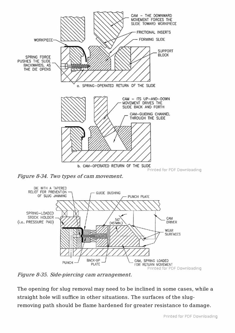
The opening for slug removal may need to be inclined in some cases, while astraight hole will suffice in other situations. The surfaces of the slug-removing path should be flame hardened for greater resistance to damage.
Figure 8-34. Two types of cam movement.
Figure 8-35. Side-piercing cam arrangement.
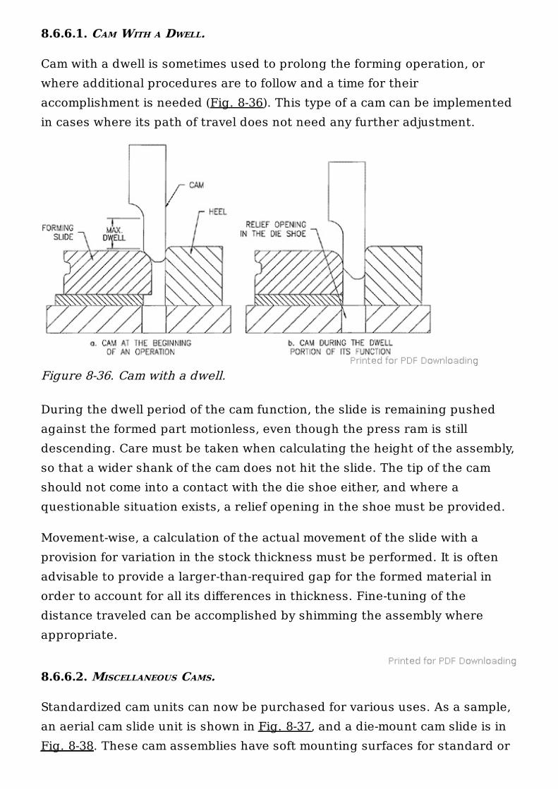
8.6.6.1. CAM WITH A DWELL.
Cam with a dwell is sometimes used to prolong the forming operation, orwhere additional procedures are to follow and a time for theiraccomplishment is needed (Fig. 8-36). This type of a cam can be implementedin cases where its path of travel does not need any further adjustment.
During the dwell period of the cam function, the slide is remaining pushedagainst the formed part motionless, even though the press ram is stilldescending. Care must be taken when calculating the height of the assembly,so that a wider shank of the cam does not hit the slide. The tip of the camshould not come into a contact with the die shoe either, and where aquestionable situation exists, a relief opening in the shoe must be provided.
Movement-wise, a calculation of the actual movement of the slide with aprovision for variation in the stock thickness must be performed. It is oftenadvisable to provide a larger-than-required gap for the formed material inorder to account for all its differences in thickness. Fine-tuning of thedistance traveled can be accomplished by shimming the assembly whereappropriate.
8.6.6.2. MISCELLANEOUS CAMS.
Standardized cam units can now be purchased for various uses. As a sample,an aerial cam slide unit is shown in Fig. 8-37, and a die-mount cam slide is inFig. 8-38. These cam assemblies have soft mounting surfaces for standard or
Figure 8-36. Cam with a dwell.
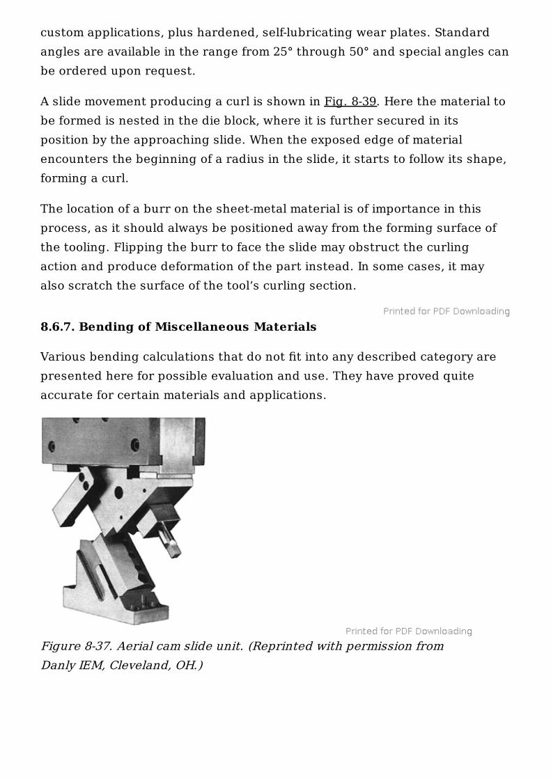
custom applications, plus hardened, self-lubricating wear plates. Standardangles are available in the range from 25° through 50° and special angles canbe ordered upon request.
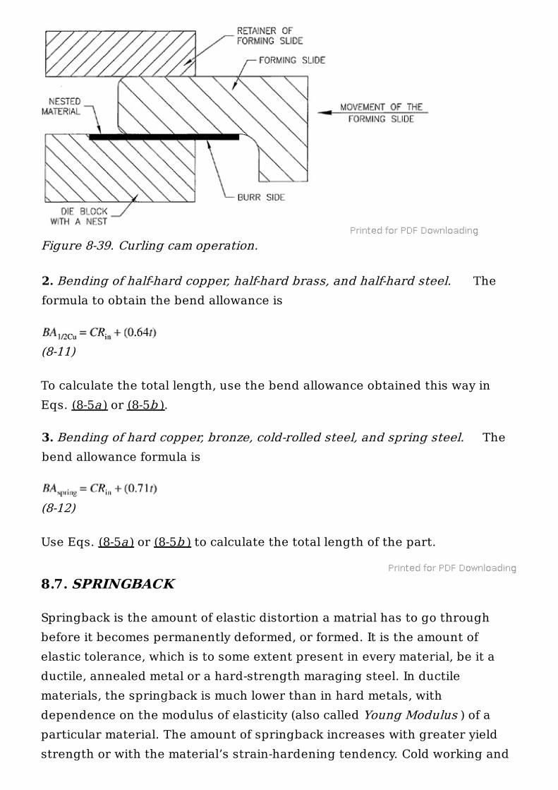
A slide movement producing a curl is shown in Fig. 8-39. Here the material tobe formed is nested in the die block, where it is further secured in itsposition by the approaching slide. When the exposed edge of materialencounters the beginning of a radius in the slide, it starts to follow its shape,forming a curl.
The location of a burr on the sheet-metal material is of importance in thisprocess, as it should always be positioned away from the forming surface ofthe tooling. Flipping the burr to face the slide may obstruct the curlingaction and produce deformation of the part instead. In some cases, it mayalso scratch the surface of the tool’s curling section.
8.6.7. Bending of Miscellaneous Materials
Various bending calculations that do not fit into any described category arepresented here for possible evaluation and use. They have proved quiteaccurate for certain materials and applications.
Figure 8-37. Aerial cam slide unit. (Reprinted with permission fromDanly IEM, Cleveland, OH.)
1. Bending of soft copper and soft brass. The formula to calculate bendallowance is Eq. (8-10). Its application is the same as previously described.
(8-10)
where R = inside radius of the bend t = material thickness C = constant, depending on the angle of the bend. For 90° bends,this value is 1.5708. For bends of different angularity, see Table 8-7.
Further calculation of the total length of the part L is performed thesame way, as shown in Eqs. (8-5a ) or (8-5b ).
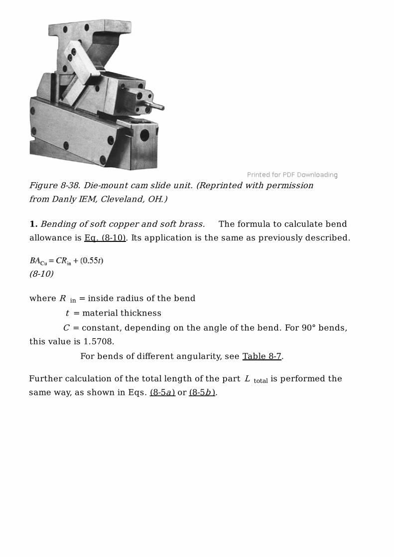
Figure 8-38. Die-mount cam slide unit. (Reprinted with permissionfrom Danly IEM, Cleveland, OH.)
in
total
2. Bending of half-hard copper, half-hard brass, and half-hard steel. Theformula to obtain the bend allowance is
(8-11)
To calculate the total length, use the bend allowance obtained this way inEqs. (8-5a ) or (8-5b ).
3. Bending of hard copper, bronze, cold-rolled steel, and spring steel. Thebend allowance formula is
(8-12)
Use Eqs. (8-5a ) or (8-5b ) to calculate the total length of the part.
8.7. SPRINGBACK
Springback is the amount of elastic distortion a matrial has to go throughbefore it becomes permanently deformed, or formed. It is the amount ofelastic tolerance, which is to some extent present in every material, be it aductile, annealed metal or a hard-strength maraging steel. In ductilematerials, the springback is much lower than in hard metals, withdependence on the modulus of elasticity (also called Young Modulus ) of aparticular material. The amount of springback increases with greater yieldstrength or with the material’s strain-hardening tendency. Cold working and
Figure 8-39. Curling cam operation.
heat treatment both increase the amount of springback in the material.Comparably, the springback of low-strength steel material will be smallerthan that of high-strength steel and springback of aluminum will be two orthree times higher yet.
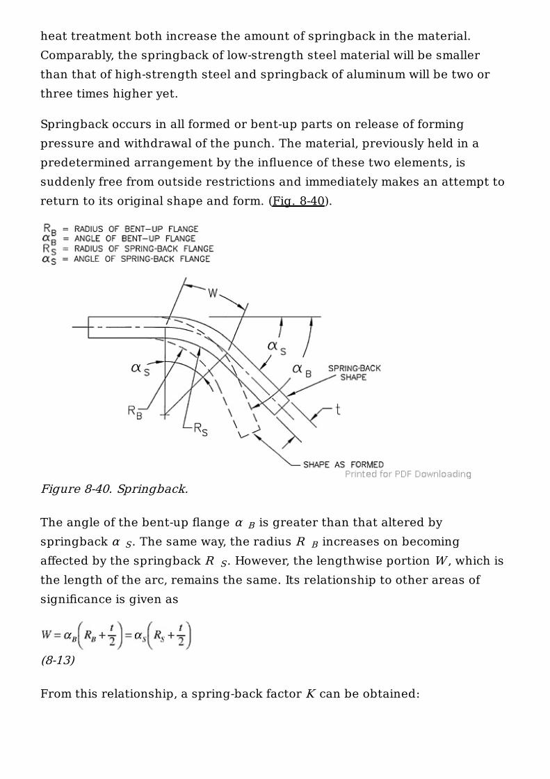
Springback occurs in all formed or bent-up parts on release of formingpressure and withdrawal of the punch. The material, previously held in apredetermined arrangement by the influence of these two elements, issuddenly free from outside restrictions and immediately makes an attempt toreturn to its original shape and form. (Fig. 8-40).
The angle of the bent-up flange α is greater than that altered byspringback α . The same way, the radius R increases on becomingaffected by the springback R . However, the lengthwise portion W , which isthe length of the arc, remains the same. Its relationship to other areas ofsignificance is given as
(8-13)
From this relationship, a spring-back factor K can be obtained:
Figure 8-40. Springback.
B
S B
S
(8-14)
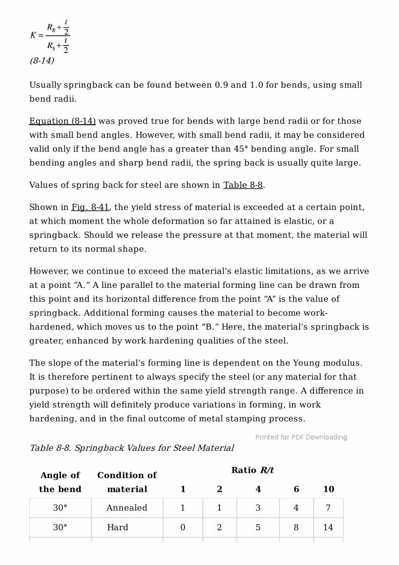
Usually springback can be found between 0.9 and 1.0 for bends, using smallbend radii.
Equation (8-14) was proved true for bends with large bend radii or for thosewith small bend angles. However, with small bend radii, it may be consideredvalid only if the bend angle has a greater than 45° bending angle. For smallbending angles and sharp bend radii, the spring back is usually quite large.
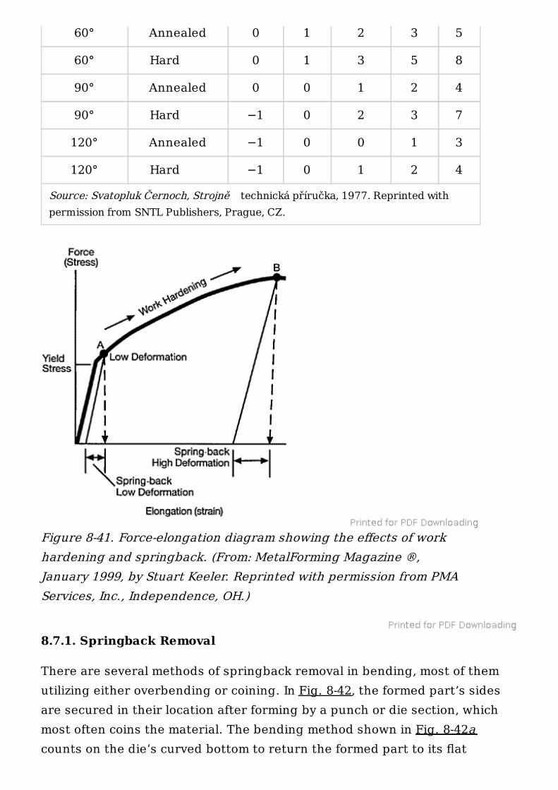
Values of spring back for steel are shown in Table 8-8.
Shown in Fig. 8-41, the yield stress of material is exceeded at a certain point,at which moment the whole deformation so far attained is elastic, or aspringback. Should we release the pressure at that moment, the material willreturn to its normal shape.
However, we continue to exceed the material’s elastic limitations, as we arriveat a point “A.” A line parallel to the material forming line can be drawn fromthis point and its horizontal difference from the point “A” is the value ofspringback. Additional forming causes the material to become work-hardened, which moves us to the point “B.” Here, the material’s springback isgreater, enhanced by work hardening qualities of the steel.
The slope of the material’s forming line is dependent on the Young modulus.It is therefore pertinent to always specify the steel (or any material for thatpurpose) to be ordered within the same yield strength range. A difference inyield strength will definitely produce variations in forming, in workhardening, and in the final outcome of metal stamping process.
Table 8-8. Springback Values for Steel Material
Angle ofthe bend
Condition ofmaterial
Ratio R/t
1 2 4 6 10
30° Annealed 1 1 3 4 7
30° Hard 0 2 5 8 14
8.7.1. Springback Removal
There are several methods of springback removal in bending, most of themutilizing either overbending or coining. In Fig. 8-42, the formed part’s sidesare secured in their location after forming by a punch or die section, whichmost often coins the material. The bending method shown in Fig. 8-42acounts on the die’s curved bottom to return the formed part to its flat
Source: Svatopluk Černoch, Strojně technická příručka, 1977. Reprinted withpermission from SNTL Publishers, Prague, CZ.
60° Annealed 0 1 2 3 5
60° Hard 0 1 3 5 8
90° Annealed 0 0 1 2 4
90° Hard −1 0 2 3 7
120° Annealed −1 0 0 1 3
120° Hard −1 0 1 2 4
Figure 8-41. Force-elongation diagram showing the effects of workhardening and springback. (From: MetalForming Magazine ®,January 1999, by Stuart Keeler. Reprinted with permission from PMAServices, Inc., Independence, OH.)
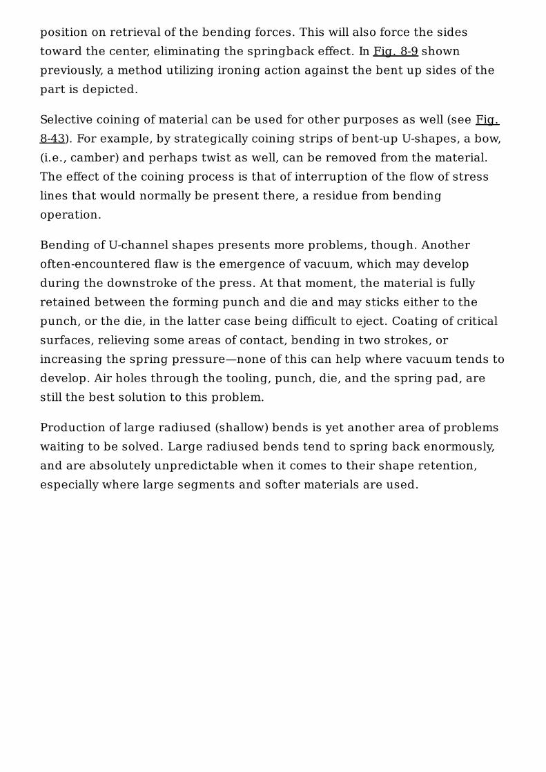
position on retrieval of the bending forces. This will also force the sidestoward the center, eliminating the springback effect. In Fig. 8-9 shownpreviously, a method utilizing ironing action against the bent up sides of thepart is depicted.
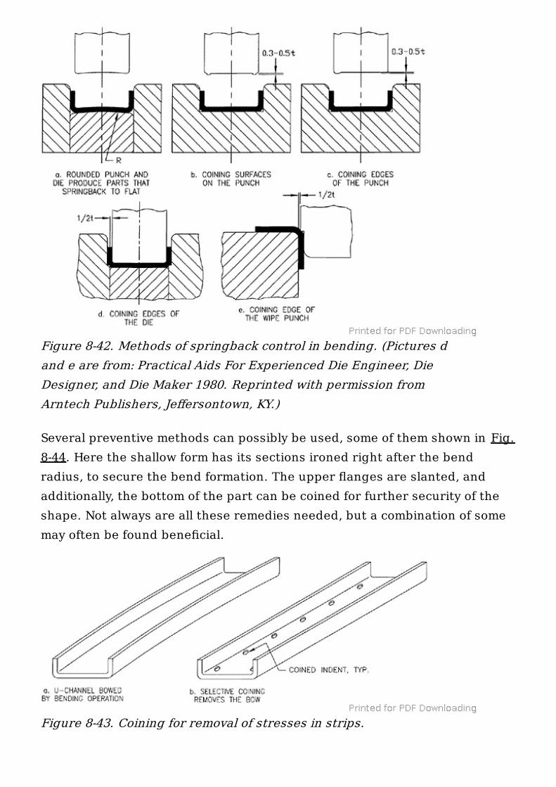
Selective coining of material can be used for other purposes as well (see Fig.8-43). For example, by strategically coining strips of bent-up U-shapes, a bow,(i.e., camber) and perhaps twist as well, can be removed from the material.The effect of the coining process is that of interruption of the flow of stresslines that would normally be present there, a residue from bendingoperation.
Bending of U-channel shapes presents more problems, though. Anotheroften-encountered flaw is the emergence of vacuum, which may developduring the downstroke of the press. At that moment, the material is fullyretained between the forming punch and die and may sticks either to thepunch, or the die, in the latter case being difficult to eject. Coating of criticalsurfaces, relieving some areas of contact, bending in two strokes, orincreasing the spring pressure—none of this can help where vacuum tends todevelop. Air holes through the tooling, punch, die, and the spring pad, arestill the best solution to this problem.
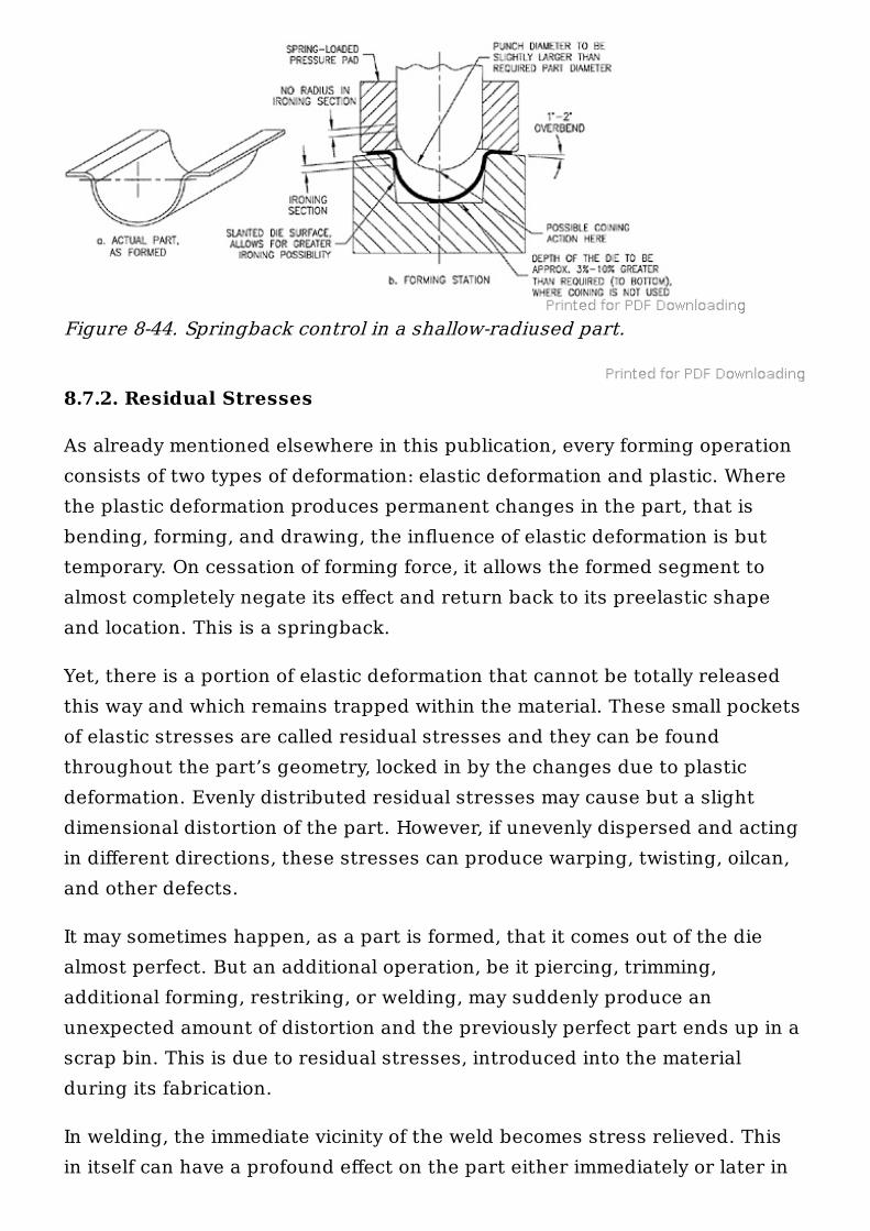
Production of large radiused (shallow) bends is yet another area of problemswaiting to be solved. Large radiused bends tend to spring back enormously,and are absolutely unpredictable when it comes to their shape retention,especially where large segments and softer materials are used.
Several preventive methods can possibly be used, some of them shown in Fig.8-44. Here the shallow form has its sections ironed right after the bendradius, to secure the bend formation. The upper flanges are slanted, andadditionally, the bottom of the part can be coined for further security of theshape. Not always are all these remedies needed, but a combination of somemay often be found beneficial.
Figure 8-42. Methods of springback control in bending. (Pictures dand e are from: Practical Aids For Experienced Die Engineer, DieDesigner, and Die Maker 1980. Reprinted with permission fromArntech Publishers, Jeffersontown, KY.)
Figure 8-43. Coining for removal of stresses in strips.
8.7.2. Residual Stresses
As already mentioned elsewhere in this publication, every forming operationconsists of two types of deformation: elastic deformation and plastic. Wherethe plastic deformation produces permanent changes in the part, that isbending, forming, and drawing, the influence of elastic deformation is buttemporary. On cessation of forming force, it allows the formed segment toalmost completely negate its effect and return back to its preelastic shapeand location. This is a springback.
Yet, there is a portion of elastic deformation that cannot be totally releasedthis way and which remains trapped within the material. These small pocketsof elastic stresses are called residual stresses and they can be foundthroughout the part’s geometry, locked in by the changes due to plasticdeformation. Evenly distributed residual stresses may cause but a slightdimensional distortion of the part. However, if unevenly dispersed and actingin different directions, these stresses can produce warping, twisting, oilcan,and other defects.
It may sometimes happen, as a part is formed, that it comes out of the diealmost perfect. But an additional operation, be it piercing, trimming,additional forming, restriking, or welding, may suddenly produce anunexpected amount of distortion and the previously perfect part ends up in ascrap bin. This is due to residual stresses, introduced into the materialduring its fabrication.
In welding, the immediate vicinity of the weld becomes stress relieved. Thisin itself can have a profound effect on the part either immediately or later in
Figure 8-44. Springback control in a shallow-radiused part.
service. Then, due to cyclic loading, all defects tend to become emphasizedwith time and may cause the part’s collapse and perhaps total destruction.
Both residual stresses and springback can bring about a host of unexpectedproblems and a sound part design, along with a good tool design, combinedwith a good manufacturing practice cannot be overemphasized. There arecertain features encountered in sheet-metal parts that almost alwaysproduce greater than necessary stresses in formed parts. Such featuresconsist mainly of sharp corners, sharp bend radii, greater differences inheight, to name but a few.
8.8. SURFACE FLATNESS AFTER BENDING
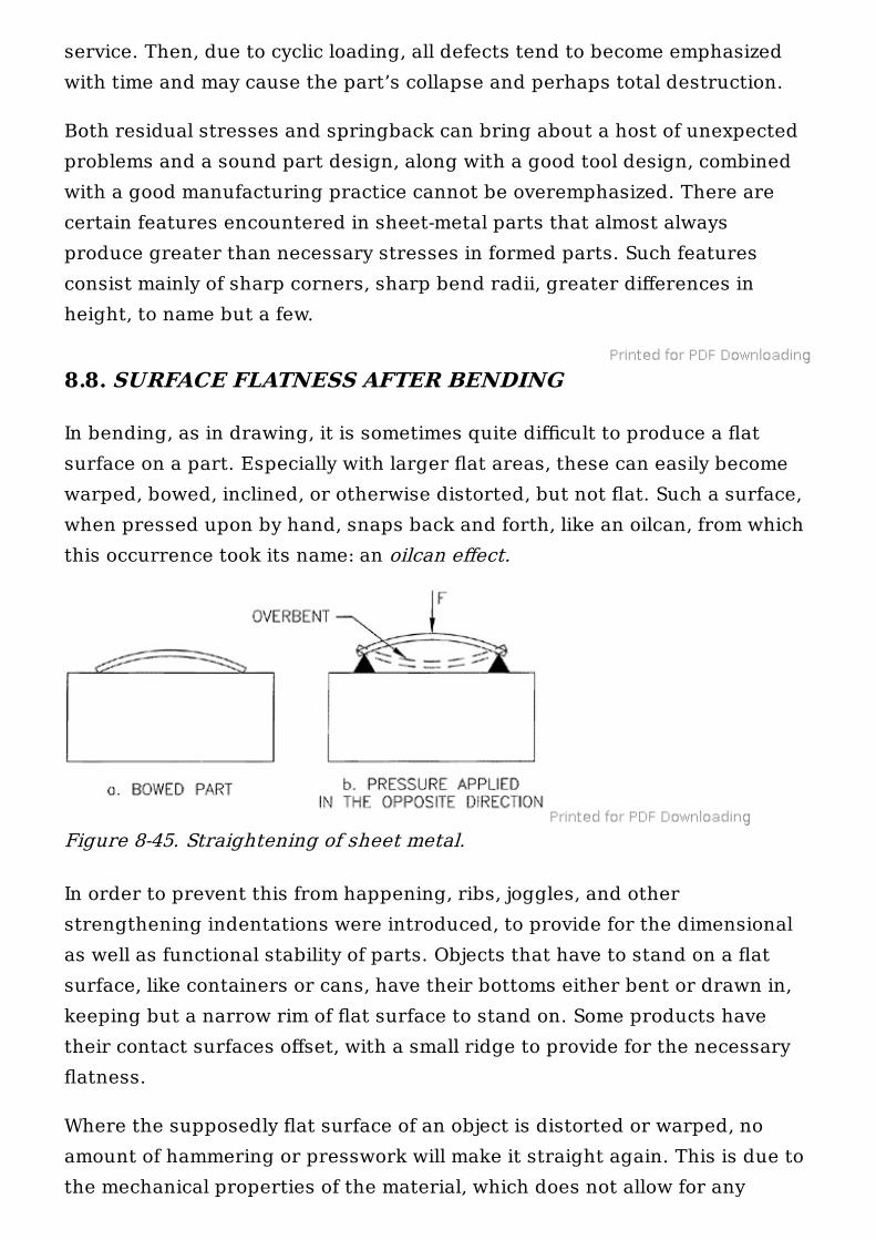
In bending, as in drawing, it is sometimes quite difficult to produce a flatsurface on a part. Especially with larger flat areas, these can easily becomewarped, bowed, inclined, or otherwise distorted, but not flat. Such a surface,when pressed upon by hand, snaps back and forth, like an oilcan, from whichthis occurrence took its name: an oilcan effect.
In order to prevent this from happening, ribs, joggles, and otherstrengthening indentations were introduced, to provide for the dimensionalas well as functional stability of parts. Objects that have to stand on a flatsurface, like containers or cans, have their bottoms either bent or drawn in,keeping but a narrow rim of flat surface to stand on. Some products havetheir contact surfaces offset, with a small ridge to provide for the necessaryflatness.
Where the supposedly flat surface of an object is distorted or warped, noamount of hammering or presswork will make it straight again. This is due tothe mechanical properties of the material, which does not allow for any
Figure 8-45. Straightening of sheet metal.
permanent alteration unless the elastic limit of the material is exceeded.
Part a in Fig. 8-45 cannot be straightened by any feasible amount of pressureapplied from above. In order to flatten this surface, it must be reversed andsupported on two extreme ends, as shown in part b. In such a position, evena minute force will produce the flattening effect.
Another way known, a part such as this can be straightened, is whensubmitted to pressures excessive of its modulus of elasticity. Usinghydraulically produced forces these methods are sometimes resorted to,lately. Of course, the cost of the necessary equipment can bring this solutionout of reach of most manufacturers.
Annealing of the part may be found of help sometimes, provided there are noexcessive residual stresses within its structure. If such is the case andresidual stresses will become relieved by the annealing process, severedistortion may result. Localized annealing by a torch was usually not foundeffective.
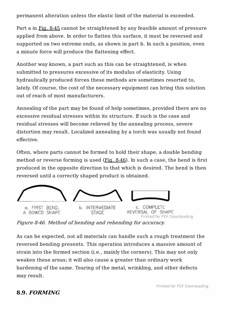
Often, where parts cannot be formed to hold their shape, a double bendingmethod or reverse forming is used (Fig. 8-46). In such a case, the bend is firstproduced in the opposite direction to that which is desired. The bend is thenreversed until a correctly shaped product is obtained.
As can be expected, not all materials can handle such a rough treatment thereversed bending presents. This operation introduces a massive amount ofstrain into the formed section (i.e., mainly the corners). This may not onlyweaken these areas; it will also cause a greater than ordinary workhardening of the same. Tearing of the metal, wrinkling, and other defectsmay result.
8.9. FORMING
Figure 8-46. Method of bending and rebending for accuracy.
Metal forming is a process totally dependent on the influence of outsidetensile forces against the structure of the material. The resulting permanentdeformation is called forming . The force-exerting instrument is the punch,which by pulling the sheet-metal material along, makes it enter the die,where it is compelled to take upon itself the impression of the assembly.
The decision if the part is to be formed or drawn is usually based on theevaluation of its shape and dimensional requirements. Drawing is utilized forthose parts made of thicker materials or for those with vertical (or slightlyinclined) walls and sharp corners at the bottom.
Since a forming die may often be instrumental in the formation of wrinkles orcause development of excessive tensile strains in the material, which awaytear the part in the process, drawing is often resorted to in such cases.
8.9.1. Forming of Singular Recesses
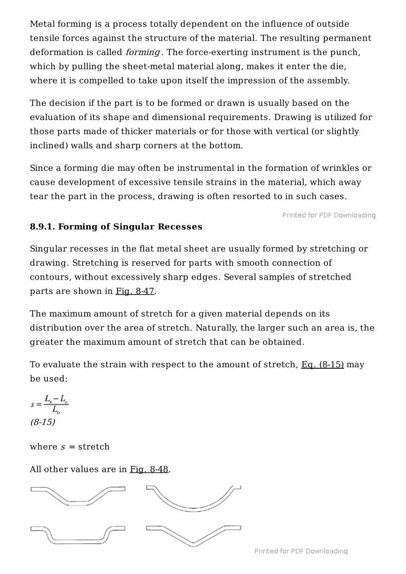
Singular recesses in the flat metal sheet are usually formed by stretching ordrawing. Stretching is reserved for parts with smooth connection ofcontours, without excessively sharp edges. Several samples of stretchedparts are shown in Fig. 8-47.
The maximum amount of stretch for a given material depends on itsdistribution over the area of stretch. Naturally, the larger such an area is, thegreater the maximum amount of stretch that can be obtained.
To evaluate the strain with respect to the amount of stretch, Eq. (8-15) maybe used:
(8-15)
where s = stretch
All other values are in Fig. 8-48.
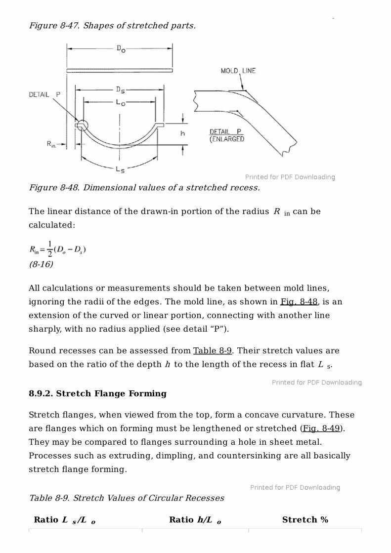
The linear distance of the drawn-in portion of the radius R can becalculated:
(8-16)
All calculations or measurements should be taken between mold lines,ignoring the radii of the edges. The mold line, as shown in Fig. 8-48, is anextension of the curved or linear portion, connecting with another linesharply, with no radius applied (see detail “P”).
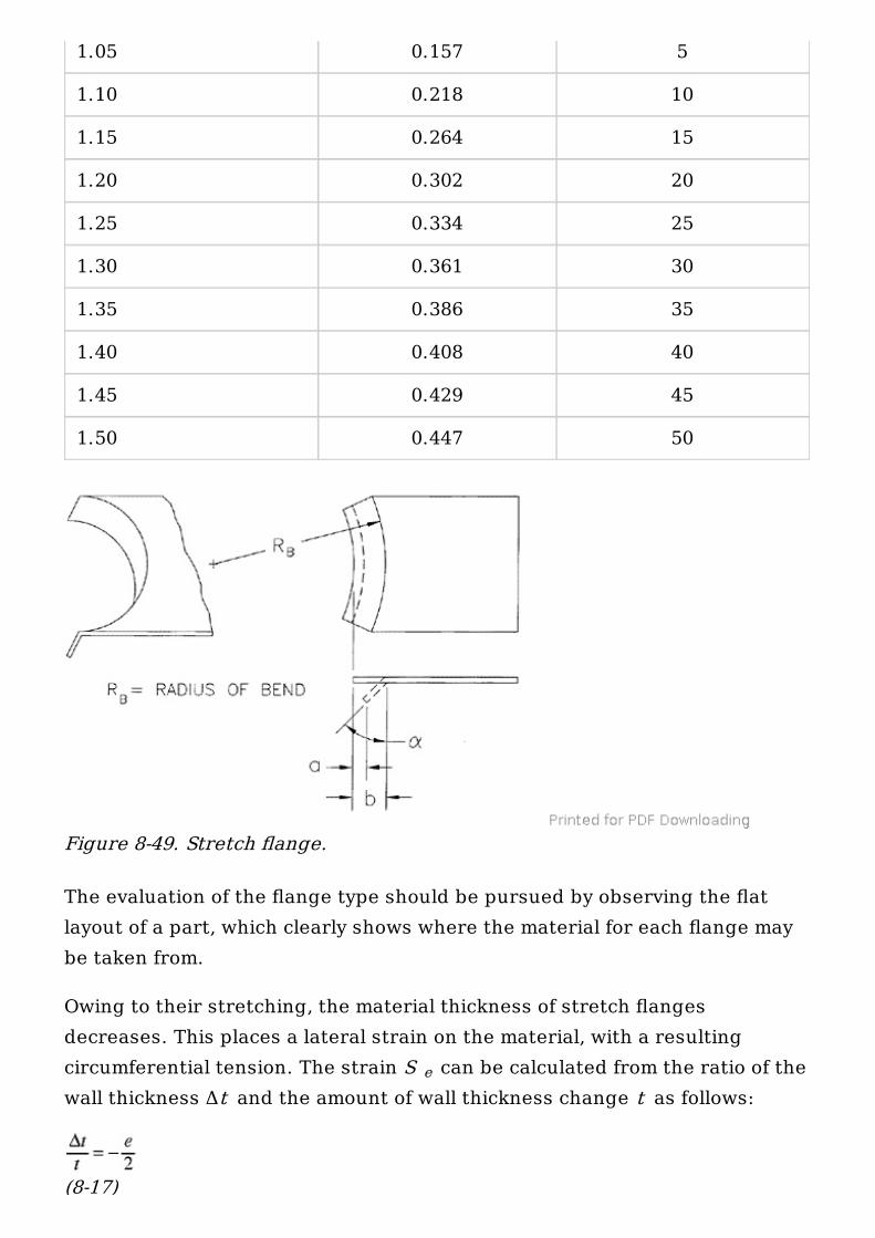
Round recesses can be assessed from Table 8-9. Their stretch values arebased on the ratio of the depth h to the length of the recess in flat L .
8.9.2. Stretch Flange Forming
Stretch flanges, when viewed from the top, form a concave curvature. Theseare flanges which on forming must be lengthened or stretched (Fig. 8-49).They may be compared to flanges surrounding a hole in sheet metal.Processes such as extruding, dimpling, and countersinking are all basicallystretch flange forming.
Table 8-9. Stretch Values of Circular Recesses
Figure 8-47. Shapes of stretched parts.
Figure 8-48. Dimensional values of a stretched recess.
in
s
Ratio L /L Ratio h/L Stretch %s o o
The evaluation of the flange type should be pursued by observing the flatlayout of a part, which clearly shows where the material for each flange maybe taken from.
Owing to their stretching, the material thickness of stretch flangesdecreases. This places a lateral strain on the material, with a resultingcircumferential tension. The strain S can be calculated from the ratio of thewall thickness Δt and the amount of wall thickness change t as follows:
(8-17)
1.05 0.157 5
1.10 0.218 10
1.15 0.264 15
1.20 0.302 20
1.25 0.334 25
1.30 0.361 30
1.35 0.386 35
1.40 0.408 40
1.45 0.429 45
1.50 0.447 50
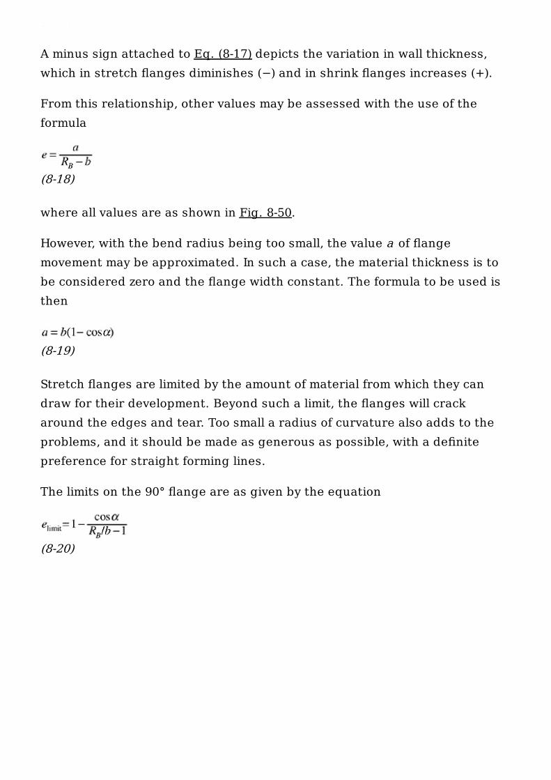
Figure 8-49. Stretch flange.
e
(8-17)
A minus sign attached to Eq. (8-17) depicts the variation in wall thickness,which in stretch flanges diminishes (−) and in shrink flanges increases (+).
From this relationship, other values may be assessed with the use of theformula
(8-18)
where all values are as shown in Fig. 8-50.
However, with the bend radius being too small, the value a of flangemovement may be approximated. In such a case, the material thickness is tobe considered zero and the flange width constant. The formula to be used isthen
(8-19)
Stretch flanges are limited by the amount of material from which they candraw for their development. Beyond such a limit, the flanges will crackaround the edges and tear. Too small a radius of curvature also adds to theproblems, and it should be made as generous as possible, with a definitepreference for straight forming lines.
The limits on the 90° flange are as given by the equation
(8-20)
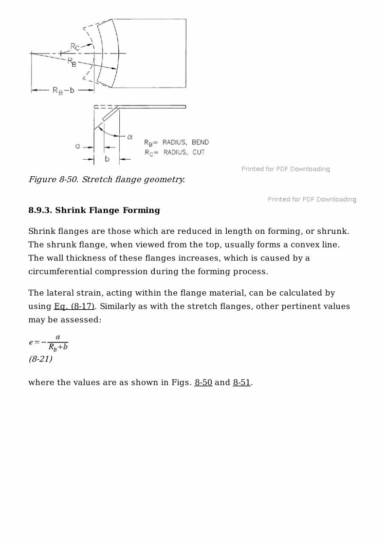
8.9.3. Shrink Flange Forming
Shrink flanges are those which are reduced in length on forming, or shrunk.The shrunk flange, when viewed from the top, usually forms a convex line.The wall thickness of these flanges increases, which is caused by acircumferential compression during the forming process.
The lateral strain, acting within the flange material, can be calculated byusing Eq. (8-17). Similarly as with the stretch flanges, other pertinent valuesmay be assessed:
(8-21)
where the values are as shown in Figs. 8-50 and 8-51.
Figure 8-50. Stretch flange geometry.
And again, the value a of flange movement may be approximated, using Eq.(8-19).
Shrink flanges are actually quite difficult to form from a flat blank. Thematerial is often reluctant to succumb to such compressive stresses and hasa tendency to wrinkle or buckle. With wider flanges, the tendency towrinkling is increased.
Buckling is found controllable where the ratio of the flange width to thematerial thickness remains within a range of 3 to 4.
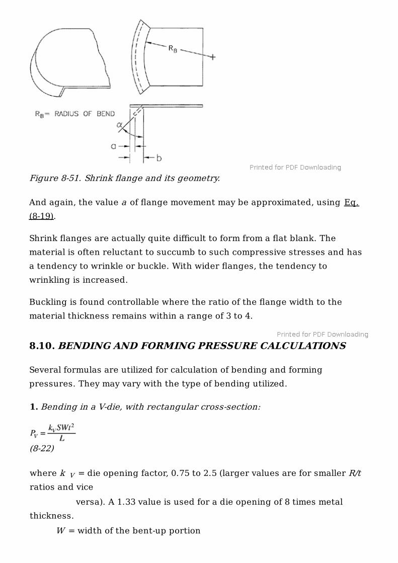
8.10. BENDING AND FORMING PRESSURE CALCULATIONS
Several formulas are utilized for calculation of bending and formingpressures. They may vary with the type of bending utilized.
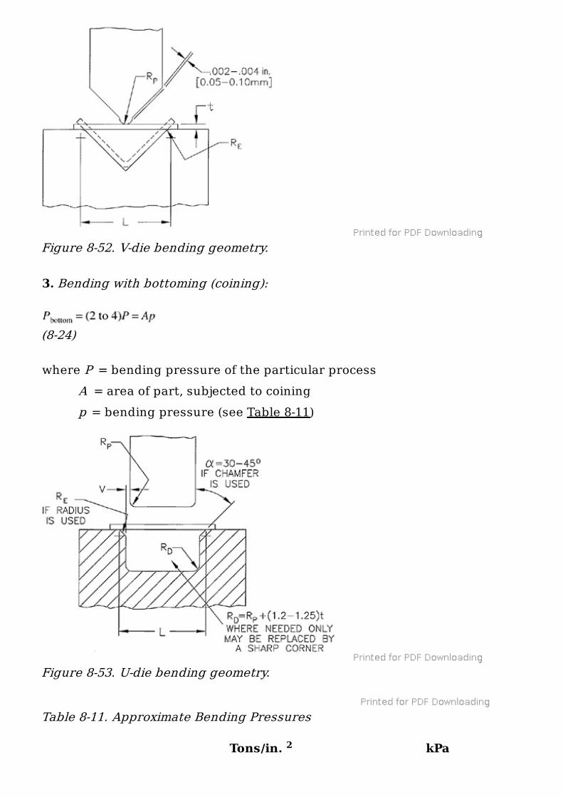
1. Bending in a V-die, with rectangular cross-section:
(8-22)
where k = die opening factor, 0.75 to 2.5 (larger values are for smaller R/tratios and vice versa). A 1.33 value is used for a die opening of 8 times metalthickness. W = width of the bent-up portion
Figure 8-51. Shrink flange and its geometry.
V
L = distance between material supports (see Fig. 8-52) S = ultimate tensile strength (Table 8-10)
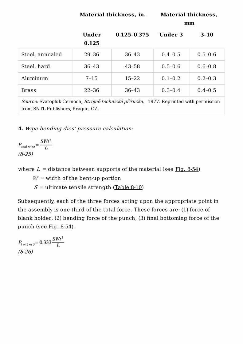
2. Bending in a U-die, equipped with a spring-loaded pressure pad:
(8-23)
where k = die opening factor, 0.4 to 10 R = radius, die edge (see Fig. 8-53) R = radius, bottom of U channel P = pressure of spring-loaded support
Table 8-10. Ultimate Tensile Strength of Materials
U
E
D
pad
Tons/In. MPa [N/mm ]
Steel, low carbon, 1025 30–51.5 410–710
Steel, medium carbon, 1045 40–91 550–1,250
Steel, high carbon, 1095 45–106.5 620–1,470
Steel, stainless, 303 42.5–62.5 585–860
Aluminum alloy, cold worked 6.0–31.5 80–435
Aluminum alloy, heat treated 11.0–41.5 150–570
Copper 16–28.5 220–390
Phosphor bronze 20–64 275–880
Zinc 9.75–15.5 135–215
2 2
3. Bending with bottoming (coining):
(8-24)
where P = bending pressure of the particular process A = area of part, subjected to coining p = bending pressure (see Table 8-11)
Table 8-11. Approximate Bending Pressures
Figure 8-52. V-die bending geometry.
Figure 8-53. U-die bending geometry.
Tons/in. kPa2
4. Wipe bending dies’ pressure calculation:
(8-25)
where L = distance between supports of the material (see Fig. 8-54) W = width of the bent-up portion S = ultimate tensile strength (Table 8-10)
Subsequently, each of the three forces acting upon the appropriate point inthe assembly is one-third of the total force. These forces are: (1) force ofblank holder; (2) bending force of the punch; (3) final bottoming force of thepunch (see Fig. 8-54).
(8-26)
Material thickness, in. Material thickness,mm
Under0.125
0.125–0.375 Under 3 3–10
Source: Svatopluk Černoch, Strojně technická příručka, 1977. Reprinted with permissionfrom SNTL Publishers, Prague, CZ.
Steel, annealed 29–36 36–43 0.4–0.5 0.5–0.6
Steel, hard 36–43 43–58 0.5–0.6 0.6–0.8
Aluminum 7–15 15–22 0.1–0.2 0.2–0.3
Brass 22–36 36–43 0.3–0.4 0.4–0.5
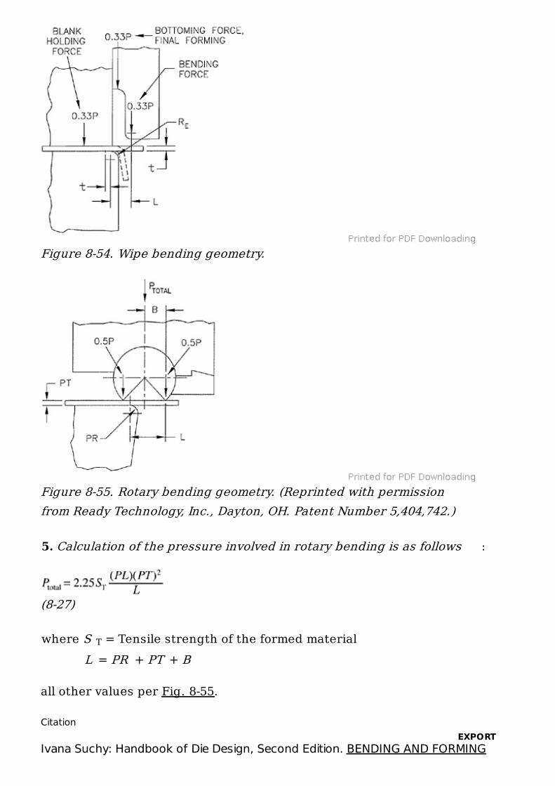
5. Calculation of the pressure involved in rotary bending is as follows :
(8-27)
where S = Tensile strength of the formed material L = PR + PT + B
all other values per Fig. 8-55.
Figure 8-54. Wipe bending geometry.
Figure 8-55. Rotary bending geometry. (Reprinted with permissionfrom Ready Technology, Inc., Dayton, OH. Patent Number 5,404,742.)
T
Citation
Ivana Suchy: Handbook of Die Design, Second Edition. BENDING AND FORMINGEXPORT

Copyright © McGraw-Hill Global Education Holdings, LLC. All rights reserved. Any use is subject to the Terms of Use. Privacy Notice and copyright information.
For further information about this site, contact us.
Designed and built using Scolaris by Semantico.
This product incorporates part of the open source Protégé system. Protégé isavailable at http://protege.stanford.edu//
OPERATIONS, Chapter (McGraw-Hill Professional, 2006 1998), AccessEngineering