Embed Size (px)
Citation preview
Journal of the Franklin Institute 348 (2011) 300–314
0016-0032/$3
doi:10.1016/j
�CorrespoE-mail ad
www.elsevier.com/locate/jfranklin
A robust vector control for induction motor driveswith an adaptive sliding-mode control law
Oscar Barambonesa,�, Patxi Alkortab
aDpto. Ingenierı́a de Sistemas y Autom �atica, EUI de Vitoria, Universidad del Paı́s Vasco, Nieves cano 12, 01006
Vitoria, SpainbDpto. Ingenierı́a de Sistemas y Autom �atica, EUI de Eibar, Universidad del Paı́s Vasco, Avda. Otaola, 29 20600
Eibar (Gipuzkoa)
Received 4 January 2010; received in revised form 24 November 2010; accepted 30 November 2010
Available online 7 December 2010
Abstract
A novel adaptive sliding-mode control system is proposed in order to control the speed of an
induction motor drive. This design employs the so-called vector (or field oriented) control theory for
the induction motor drives. The sliding-mode control is insensitive to uncertainties and presents an
adaptive switching gain to relax the requirement for the bound of these uncertainties. The switching
gain is adapted using a simple algorithm which does not imply a high computational load. Stability
analysis based on Lyapunov theory is also performed in order to guarantee the closed loop stability.
Finally, simulation results show not only that the proposed controller provides high-performance
dynamic characteristics, but also that this scheme is robust with respect to plant parameter variations
and external load disturbances.
& 2010 The Franklin Institute. Published by Elsevier Ltd. All rights reserved.
1. Introduction
The induction motor is a complex structure that converts electrical energy into mechanicalenergy. Although induction machines were introduced more than a hundred years ago, theresearch and development in this area appears to be never-ending. Traditionally, AC machineswith a constant frequency sinusoidal power supply have been used in constant-speedapplications, whereas DC machines were preferred for variable speed drives, since they present
2.00 & 2010 The Franklin Institute. Published by Elsevier Ltd. All rights reserved.
.jfranklin.2010.11.008
nding author. Tel.: þ34 945013235; fax: þ34 945013270.
dress: [email protected] (O. Barambones).
O. Barambones, P. Alkorta / Journal of the Franklin Institute 348 (2011) 300–314 301
a simpler control. Besides, AC machines presented some disadvantages in comparison withDC ones, as higher cost, higher rotor inertia and maintenance problems. Nevertheless, in thelast two or three decades we have seen extensive research and development efforts in variable-frequency, variable-speed ACmachine drives technology [1], which have overcome some of theabove disadvantages of the AC motors.
The development of field oriented control in the beginning of 1970s made it feasible tocontrol the induction motor as a separately excited DC motor [1–3]. In this sense, the field-oriented technique guarantees the decoupling of torque and flux control commands for theinduction motor. This means that when the flux is governed by means of controlling thecurrent id, the torque is not affected. Similarly, when the torque is governed by controllingthe current iq, the flux is not affected and, therefore, it can be achieved transient responseas fast as in the case of DC machines.
On the other hand, when dealing with indirect field-oriented control of inductionmotors, a knowledge of rotor speed is required in order to orient the injected stator currentvector and to establish an adequate speed feedback control. Although the use of a fluxestimator in direct field oriented control eliminates the need of the speed sensor in order toorient the injected stator current vector, this method is not practical. This is because theflux estimator does not work properly in a low speed region. The flux estimator presents apole on the origin of the S plane (pure integrator), and therefore it is very sensitive to theoffset of the voltage sensor and the parameter variations.
However, the speed or position sensor of induction motor still limits its applications tosome special environments not only due to the difficulties of mounting the sensor, but alsobecause of the need of low cost and reliable systems. The research and development work ona sensorless driver for the AC motor is progressing greatly. Much work has been done usingthe field oriented based method approach [4–7]. In these schemes the speed is obtained basedon the measurement of stator voltages and currents. On the other hand, the induction motormodel can be obtained using a Neural Network approach. In the work of Alanis et al. [8]a discrete-time nonlinear system identification via recurrent high order neural networks isproposed. In this work a sixth-order discrete-time induction motor model in the stator fixedreference frame is calculated using the proposed recurrent neural networks scheme.
Nevertheless, the robustness to parameter variations and load disturbances in theinduction machines still deserves to be further studied and, in particular, special attentionshould be paid to the low speed region transients.
Thus, the performance of the field oriented control strongly depends on uncertainties,which are usually due to unknown parameters, parameter variations, external loaddisturbances, unmodelled and nonlinear dynamics, etc. Therefore, many studies have beenmade on the motor drives in order to preserve the performance under these parametervariations and external load disturbances, such as nonlinear control, optimal control,variable structure system control, adaptive control, neural control and fuzzy control[9–13]. Recently, the genetic algorithm approach has also been used in order to control theelectric motors. The work of Montazeri-Gh et al. [14], describes the application of thegenetic algorithm for the optimization of the control parameters in parallel hybrid electricvehicles driven by an electric induction machine.
To overcome the above system uncertainties, the variable structure control strategy usingthe sliding-mode has been focussed on many studies and research for the control of the ACservo drive system in the past decade [15–19]. The sliding-mode control can offer many goodproperties, such as good performance against unmodelled dynamics, insensitivity to parameter
O. Barambones, P. Alkorta / Journal of the Franklin Institute 348 (2011) 300–314302
variations, external disturbance rejection and fast dynamic response [20]. These advantages ofthe sliding-mode control may be employed in the position and speed control of an AC servosystem.The robust properties of the sliding-mode systems are also been employed in the
observers design [21]. In this work an observer-based sliding-mode control problem isinvestigated for a class of uncertain delta operator systems with nonlinear exogenousdisturbance and the control system stability is demonstrated using the Lyapunov stabilitytheory. In the work of Boiko [22] the estimation precision and bandwidth of sliding-modeobservers are analyzed in the frequency domain for different settings of the observer designparameters. In this paper an example of sliding-mode observer design for estimation of DCmotor speed from the measurements of armature current is considered.A position-and-velocity sensorless control for brushless DC motors using an adaptive
sliding mode observer is proposed in Furuhashi [23]. In this work a sliding-mode observeris proposed in order to estimate the position and velocity for brushless DC motors. Then,the velocity of the system is regulated using a PI control. A sensorless sliding-mode torquecontrol for induction motors used in hybrid electric vehicle applications is developed inProca et al. [24]. The sliding-mode control proposed in this work allows for fast and precisetorque tracking over a wide range of speed. The paper also presents the identification andparameter estimation of an induction motor model with varying parameters. In the paper[25] a survey of applications of second-order sliding-mode control to mechanical systems ispresented. In this paper different second-order sliding-mode controllers, previouslypresented in the literature, are shown and some challenging control problems involvingmechanical systems are addressed and solved. A robust sliding-mode sensorless speed-control scheme of a voltage-fed induction motor is proposed in Rashed et al. [26]. In thiswork a second-order sliding mode is proposed in order to reduce the chattering problemthat usually appears in the traditional sliding-mode controllers. In the work of Aurora andFerrara [27] a sliding-mode control algorithm for current-fed induction motors ispresented. In this paper is proposed an adaptive second-order sliding-mode observer forspeed and rotor flux, and the load torque and the rotor time constant are also estimated.The higher order sliding mode (HOSM) proposed in this work, present some advantages over
standard sliding-mode control schemes, one of the most important is the chattering reduction.However in the HOSM an accurate knowledge of rotor flux and machine parameters is the keyfactor in order to obtain a high-performance and high-efficiency induction-motor controlscheme. Then, these control schemes require a more precise knowledge of the system parametersor the use of estimators in order to calculate the system parameters, which implies morecomputational cost than traditional sliding-mode controllers.On the other hand, the sliding control schemes require prior knowledge of the upper bound
for the system uncertainties since this bound is employed in the switching gain calculation.It should be noted that the choice of such bound may not be easily obtained due to thecomplicated structure of the uncertainties in practical control systems [28,29]. Moreover, thisupper bound should be determined as accurately as possible, because the value to beconsidered for the sliding gain increases with the bound, and therefore the control effort will bealso proportional to this bound. Hence, a high upper bound for the system uncertaintiesimplies more control effort and the problem of the chattering will be increased.In order to surmount this drawback, in this paper is proposed an adaptive law in order
to calculate the sliding gain. Therefore, in our proposed adaptive sliding-mode controlscheme we do not need to calculate an upper bound of the system uncertainties, which
O. Barambones, P. Alkorta / Journal of the Franklin Institute 348 (2011) 300–314 303
greatly simplifies the controller design. Moreover, this upper bound can be unknown andcan be variable along the time because the sliding gain is adapted on-line.
In this sense, this paper presents a new sensorless vector control scheme consisting onthe one hand of a speed estimation algorithm so that there is no need for a speed sensorand on the other hand of an adaptative variable structure control law with an integralsliding surface that compensates for the uncertainties in the system. In the proposedadaptive sliding-mode control scheme, unlike the traditional sliding-mode control schemes,the sliding gain is not calculated in advance, because it is estimated on-line in order tocompensate the present system uncertainties that can be variables along the time.
Using this variable structure control in the induction motor drive, the controlled speed isinsensitive to variations in the motor parameters and load disturbances. This variablestructure control provides a good transient response and exponential convergence of thespeed trajectory tracking despite parameter uncertainties and load torque disturbances.
The closed loop stability of the proposed scheme is demonstrated using Lyapunovstability theory, and the exponential convergence of the controlled speed is also provided.
This report is organized as follows. The rotor speed estimation is introduced in Section 2.Then, the proposed robust speed control with adaptative sliding gain is presented in Section 3.In Section 4, some simulation results are presented. Finally, concluding remarks are stated inthe last section.
2. Rotor speed computation
Many schemes based on simplified motor models have been devised to sense the speed ofthe induction motor from measured terminal quantities for control purposes. In order toobtain an accurate dynamic representation of the motor speed, it is necessary to base thecalculation on the coupled circuit equations of the motor.
Since the motor voltages and currents are measured in a stationary frame of reference, itis also convenient to express these equations in that stationary frame.
From the stator voltage equations in the stationary frame it is obtained [3]:
_cdr ¼Lr
Lm
vds�Lr
Lm
Rs þ sLs
d
dt
� �ids ð1Þ
_cqr ¼Lr
Lm
vqs�Lr
Lm
Rs þ sLs
d
dt
� �iqs ð2Þ
where c is the flux linkage; L is the inductance; v is the voltage; R is the resistance; i is thecurrent and s ¼ 1�L2
m=ðLrLsÞ is the motor leakage coefficient. The subscripts r and s
denote respectively the rotor and stator values referred to the stator, and the subscripts d
and q denote the dq-axis components in the stationary reference frame.The rotor flux equations in the stationary frame are [3]
_cdr ¼Lm
Tr
ids�wrcqr�1
Tr
cdr ð3Þ
_cqr ¼Lm
Tr
iqs þ wrcdr�1
Tr
cqr ð4Þ
where wr is the rotor electrical speed and Tr=Lr/Rr is the rotor time constant.
O. Barambones, P. Alkorta / Journal of the Franklin Institute 348 (2011) 300–314304
The angle ye of the rotor flux vector (cr ) in relation to the d-axis of the stationary frameis defined as follows:
ye ¼ arctancqr
cdr
� �ð5Þ
being its derivative:
_ye ¼ we ¼cdr
_cqr�cqr_cdr
c2dr þ c2
qr
ð6Þ
Substituting Eqs. (3) and (4) in Eq. (6) it is obtained:
we ¼ wr�Lm
Tr
cdriqs�cqrids
c2dr þ c2
qr
!ð7Þ
Then, substituting Eq. (6) in Eq. (7), and solving for wr we obtain
wr ¼1
c2r
cdr_cqr�cqr
_cdr�Lm
Tr
ðcdriqs�cqridsÞ
� �ð8Þ
where c2r ¼ c2
dr þ c2qr.
Therefore, given a complete knowledge of the motor parameters, the instantaneousspeed wr can be calculated from the previous equation, where the stator measured currentand voltages, and the rotor flux estimation obtained from a rotor flux observer based onEqs. (1) and (2) have been employed.
3. Variable structure robust speed control with adaptive sliding gain
In general, the mechanical equation of an induction motor can be written as
J _wm þ Bwm þ TL ¼ Te ð9Þ
where J and B are the inertia constant and the viscous friction coefficient of the inductionmotor system respectively; TL is the external load; wm is the rotor mechanical speed inangular frequency, which is related to the rotor electrical speed by wm=2wr/p where p is thepole numbers, and Te denotes the generated torque of an induction motor, defined as [3]
Te ¼3p
4
Lm
Lr
ðcedri
eqs�c
eqri
edsÞ ð10Þ
where cedr and ce
qr are the rotor-flux linkages, the subscript ‘e’ denotes that the quantity isreferred to the synchronously rotating reference frame; iqs
e and idse are the stator currents,
and p is the pole number.The relation between the synchronously rotating reference frame and the stationary
reference frame is computed by the so-called reverse Park’s transformation:
xa
xb
xc
264
375 ¼
cosðyeÞ �sinðyeÞ
cosðye�2p=3Þ �sinðye�2p=3Þ
cosðye þ 2p=3Þ �sinðye þ 2p=3Þ
264
375 xd
xq
" #ð11Þ
where ye is the angle position between the d-axis of the synchronously rotating and thestationary reference frames, and the quantities are assumed to be balanced.
O. Barambones, P. Alkorta / Journal of the Franklin Institute 348 (2011) 300–314 305
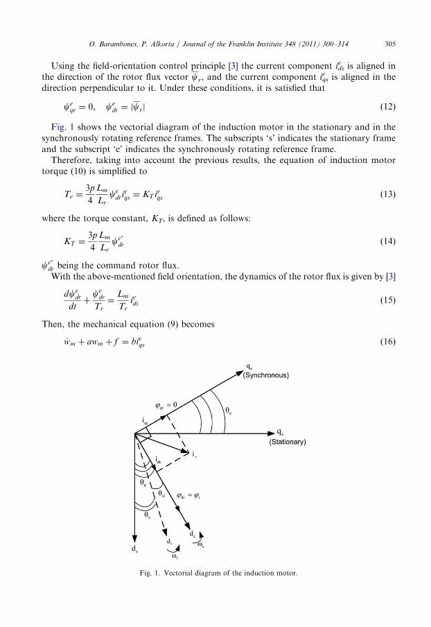
Using the field-orientation control principle [3] the current component idse is aligned in
the direction of the rotor flux vector cr, and the current component iqse is aligned in the
direction perpendicular to it. Under these conditions, it is satisfied that
ceqr ¼ 0; ce
dr ¼ jcrj ð12Þ
Fig. 1 shows the vectorial diagram of the induction motor in the stationary and in thesynchronously rotating reference frames. The subscripts ‘s’ indicates the stationary frameand the subscript ‘e’ indicates the synchronously rotating reference frame.
Therefore, taking into account the previous results, the equation of induction motortorque (10) is simplified to
Te ¼3p
4
Lm
Lr
cedri
eqs ¼ KT ie
qs ð13Þ
where the torque constant, KT, is defined as follows:
KT ¼3p
4
Lm
Lr
ce�
dr ð14Þ
ce�
dr being the command rotor flux.With the above-mentioned field orientation, the dynamics of the rotor flux is given by [3]
dcedr
dtþ
cedr
Tr
¼Lm
Tr
ieds ð15Þ
Then, the mechanical equation (9) becomes
_wm þ awm þ f ¼ bieqs ð16Þ
Fig. 1. Vectorial diagram of the induction motor.
O. Barambones, P. Alkorta / Journal of the Franklin Institute 348 (2011) 300–314306
where the parameters are defined as
a ¼B
J; b ¼
KT
J; f ¼
TL
Jð17Þ
Now, we are going to consider the previous mechanical equation (16) with uncertaintiesas follows:
_wm ¼ �ðaþ DaÞwm�ðf þ Df Þ þ ðbþ DbÞieqs ð18Þ
where the terms Da, Db and Df represent the uncertainties of the terms a, b and f
respectively. It should be noted that these uncertainties are unknown, and that the precisecalculation of an upper bound is, in general, rather difficult to achieve.Let us define the tracking speed error as follows:
eðtÞ ¼ wmðtÞ�w�mðtÞ ð19Þ
where wmn is the rotor speed command.
Taking the derivative of the previous equation with respect to time yields
_eðtÞ ¼ _wm� _w�m ¼ �aeðtÞ þ uðtÞ þ dðtÞ ð20Þ
where the following terms have been collected in the signal u(t):
uðtÞ ¼ bieqsðtÞ�aw�mðtÞ�f ðtÞ� _w�mðtÞ ð21Þ
and the uncertainty terms have been collected in the signal d(t),
dðtÞ ¼ �DawmðtÞ�Df ðtÞ þ DbieqsðtÞ ð22Þ
To compensate for the above described uncertainties present in the system, a slidingadaptive control scheme is proposed. In the sliding control theory, the switching gain mustbe constructed so as to attain the sliding condition [20,30]. In order to meet this condition asuitable choice of the sliding gain should be made to compensate for the uncertainties. Toselect the sliding gain vector, an upper bound of the parameter variations, unmodelleddynamics, noise magnitudes, etc. should be given, but in practical applications there aresituations in which these bounds are unknown, or at least difficult to calculate. A solutioncould be to choose a sufficiently high value for the sliding gain, but this approach couldcause a too high control signal, or at least more control activity than needed in order toachieve the control objective.One possible way to overcome this difficulty is to estimate the gain and to update it by
means of some adaptation law, so that the sliding condition is achieved.Now, we are going to propose the sliding variable S(t) with an integral component as
SðtÞ ¼ eðtÞ þ
Z t
0
ðaþ kÞeðtÞ dt ð23Þ
where k is a constant gain, and a is a parameter that was already defined in Eq. (17).Then the sliding surface is defined as
SðtÞ ¼ eðtÞ þ
Z t
0
ðaþ kÞeðtÞ dt ¼ 0 ð24Þ
Now, we are going to design a variable structure speed controller, that incorporates anadaptive sliding gain, in order to control the AC motor drive
uðtÞ ¼ �keðtÞ�b̂ðtÞg sgnðSÞ ð25Þ
O. Barambones, P. Alkorta / Journal of the Franklin Institute 348 (2011) 300–314 307
where the k is the gain defined previously, b̂ is the estimated switching gain, g is a positiveconstant, S is the sliding variable defined in Eq. (23) and sgnð�Þ is the sign function.
The switching gain b̂ is adapted according to the following updating law:
_̂b ¼ gjSj; b̂ð0Þ ¼ 0 ð26Þ
where g is a positive constant that let us choose the adaptation speed for the sliding gain.In order to obtain the speed trajectory tracking, the following assumptions should be
formulated:
ðA1Þ
The gain k must be chosen so that the term (aþk) is strictly positive. Therefore theconstant k should be k4�a.ðA2Þ
There exits an unknown finite non-negative switching gain b such thatb4dmax þ Z; Z40
where dmaxZjdðtÞj 8t and Z is a positive constant.Note that this condition only implies that the uncertainties of the system are boundedmagnitudes.
ðA3Þ
The constant g must be chosen so that gZ1.Theorem 1. Consider the induction motor given by Eq. (18). Then, if assumptions ðA1Þ–ðA3Þare verified, the control law (25) leads the rotor mechanical speed wm(t) so that the speed
tracking error e(t)=wm(t)�wmn (t) tends to zero as the time tends to infinity.
The proof of this theorem will be carried out using the Lyapunov stability theory.
Proof. Define the Lyapunov function candidate:
V ðtÞ ¼1
2SðtÞSðtÞ þ
1
2~bðtÞ ~bðtÞ ð27Þ
where S(t) is the sliding variable defined previously and ~bðtÞ ¼ b̂ðtÞ�bIts time derivative is calculated as
_V ðtÞ ¼ SðtÞ _SðtÞ þ ~bðtÞ _~b ðtÞ
¼ S½_e þ ðaþ kÞe� þ ~bðtÞ _̂b ðtÞ¼ S½ð�aeþ uþ dÞ þ ðkeþ aeÞ� þ ~bgjSj
¼ S½uþ d þ ke� þ ðb̂�bÞgjSj
¼ S½�ke�b̂gsgnðSÞ þ d þ ke� þ ðb̂�bÞgjSj
¼ S½d�b̂gsgnðSÞ� þ b̂gjSj�bgjSj
¼ dS�b̂gjSj þ b̂gjSj�bgjSj ð28Þ
rjdjjSj�bgjSjrjdjjSj�ðdmax þ ZÞgjSj¼ jdjjSj�dmaxgjSj�ZgjSjr�ZgjSj ð29Þ
O. Barambones, P. Alkorta / Journal of the Franklin Institute 348 (2011) 300–314308
then
_V ðtÞr0 ð30Þ
It should be noted that Eqs. (23), (20), (25) and (26), and the assumptions ðA2Þ and ðA3Þhave been used in the proof. &
Using Lyapunov’s direct method, since V(t) is clearly positive-definite, _V ðtÞ is negativesemidefinite and V(t) tends to infinity as S(t) and ~bðtÞ tends to infinity, then the equilibriumat the origin ½SðtÞ; ~bðtÞ� ¼ ½0; 0� is globally stable, and therefore the variables S(t) and ~bðtÞare bounded. Then, since S(t) is bounded one has that e(t) is also bounded.Besides, computing the derivative of Eq. (23), it is obtained:
_SðtÞ ¼ _eðtÞ þ ðaþ kÞeðtÞ ð31Þ
then, substituting Eq. (20) in Eq. (31),
_SðtÞ ¼ �aeðtÞ þ uðtÞ þ dðtÞ þ ðaþ kÞeðtÞ
¼ keðtÞ þ dðtÞ þ uðtÞ ð32Þ
From Eq. (32) we can conclude that _SðtÞ is bounded because e(t), u(t) and d(t) arebounded.Now, from Eq. (28) it is deduced that
€V ðtÞ ¼ d _SðtÞ�bgd
dtjSðtÞj ð33Þ
which is a bounded quantity because _SðtÞ is bounded.Under these conditions, since €V is bounded, _V is a uniformly continuous function, so
Barbalat’s lemma let us conclude that _V-0 as t-1, which implies that SðtÞ-0 as t-1.Therefore S(t) tends to zero as the time t tends to infinity. Moreover, all trajectories
starting off the sliding surface S=0must reach it asymptotically and then will remain on thissurface. This system’s behavior, once on the sliding surface is usually called sliding mode [20].When the sliding mode occurs on the sliding surface (24), then SðtÞ ¼ _SðtÞ ¼ 0, and
therefore the dynamic behavior of the tracking problem (20) is equivalently governed bythe following equation:
_SðtÞ ¼ 0) _eðtÞ ¼ �ðaþ kÞeðtÞ ð34Þ
Then, under assumption ðA1Þ, the tracking error e(t) converges to zero exponentially.It should be noted that, a typical motion under sliding-mode control consists of a reaching
phase during which trajectories starting off the sliding surface S=0 move towards it andreach it, followed by a sliding phase during which the motion is confined to this surface andwhere the system tracking error, represented by the reduced-order model (34), tends to zero.Finally, the torque current command, iqs
en(t), can be obtained directly substituting Eq. (25)in Eq. (21):
ie�qs ðtÞ ¼
1
b½ke�b̂gsgnðSÞ þ aw�m þ _w�m þ f � ð35Þ
Therefore, the proposed variable structure speed control with adaptive sliding gainresolves the speed tracking problem for the induction motor, with uncertainties inmechanical parameters and load torque.
O. Barambones, P. Alkorta / Journal of the Franklin Institute 348 (2011) 300–314 309
4. Simulation results
In this section we will study the speed regulation performance of the proposed adaptivesliding-mode field oriented control versus speed reference and load torque variations bymeans of simulation examples. In particular, the example presented consist of a repre-sentative speed reference tracking problem, combined with load torque variations duringthe evolution of the experiment and considering a certain degree of uncertainty, in order toattain a complete scope of the behavior of the system.
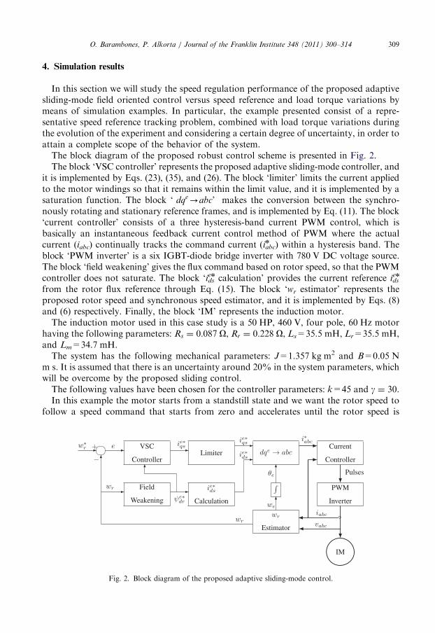
The block diagram of the proposed robust control scheme is presented in Fig. 2.The block ‘VSC controller’ represents the proposed adaptive sliding-mode controller, and
it is implemented by Eqs. (23), (35), and (26). The block ‘limiter’ limits the current appliedto the motor windings so that it remains within the limit value, and it is implemented by asaturation function. The block ‘ dqe-abc’ makes the conversion between the synchro-nously rotating and stationary reference frames, and is implemented by Eq. (11). The block‘current controller’ consists of a three hysteresis-band current PWM control, which isbasically an instantaneous feedback current control method of PWM where the actualcurrent (iabc) continually tracks the command current (iabc
n ) within a hysteresis band. Theblock ‘PWM inverter’ is a six IGBT-diode bridge inverter with 780 V DC voltage source.The block ‘field weakening’ gives the flux command based on rotor speed, so that the PWMcontroller does not saturate. The block ‘ids
en calculation’ provides the current reference idsen
from the rotor flux reference through Eq. (15). The block ‘wr estimator’ represents theproposed rotor speed and synchronous speed estimator, and it is implemented by Eqs. (8)and (6) respectively. Finally, the block ‘IM’ represents the induction motor.
The induction motor used in this case study is a 50 HP, 460 V, four pole, 60 Hz motorhaving the following parameters: Rs ¼ 0:087 O, Rr ¼ 0:228 O, Ls=35.5 mH, Lr=35.5 mH,and Lm=34.7 mH.
The system has the following mechanical parameters: J=1.357 kg m2 and B=0.05 Nm s. It is assumed that there is an uncertainty around 20% in the system parameters, whichwill be overcome by the proposed sliding control.
The following values have been chosen for the controller parameters: k=45 and g ¼ 30.In this example the motor starts from a standstill state and we want the rotor speed to
follow a speed command that starts from zero and accelerates until the rotor speed is
Fig. 2. Block diagram of the proposed adaptive sliding-mode control.
O. Barambones, P. Alkorta / Journal of the Franklin Institute 348 (2011) 300–314310
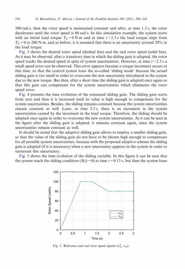
100 rad/s, then the rotor speed is maintained constant and after, at time 1.3 s, the rotordecelerates until the rotor speed is 80 rad/s. In this simulation example, the system startswith an initial load torque TL=0 N m and at time t=2.3 s the load torque steps fromTL=0 to 200 N m, and as before, it is assumed that there is an uncertainty around 20% inthe load torque.Fig. 3 shows the desired rotor speed (dashed line) and the real rotor speed (solid line).
As it may be observed, after a transitory time in which the sliding gain is adapted, the rotorspeed tracks the desired speed in spite of system uncertainties. However, at time t=2.3 s asmall speed error can be observed. This error appears because a torque increment occurs atthis time, so that the control system loses the so-called ‘sliding mode’ because the actualsliding gain is too small in order to overcome the new uncertainty introduced in the systemdue to the new torque. But then, after a short time the sliding gain is adapted once again sothat this gain can compensate for the system uncertainties which eliminates the rotorspeed error.Fig. 4 presents the time evolution of the estimated sliding gain. The sliding gain starts
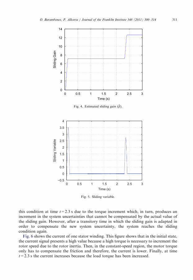
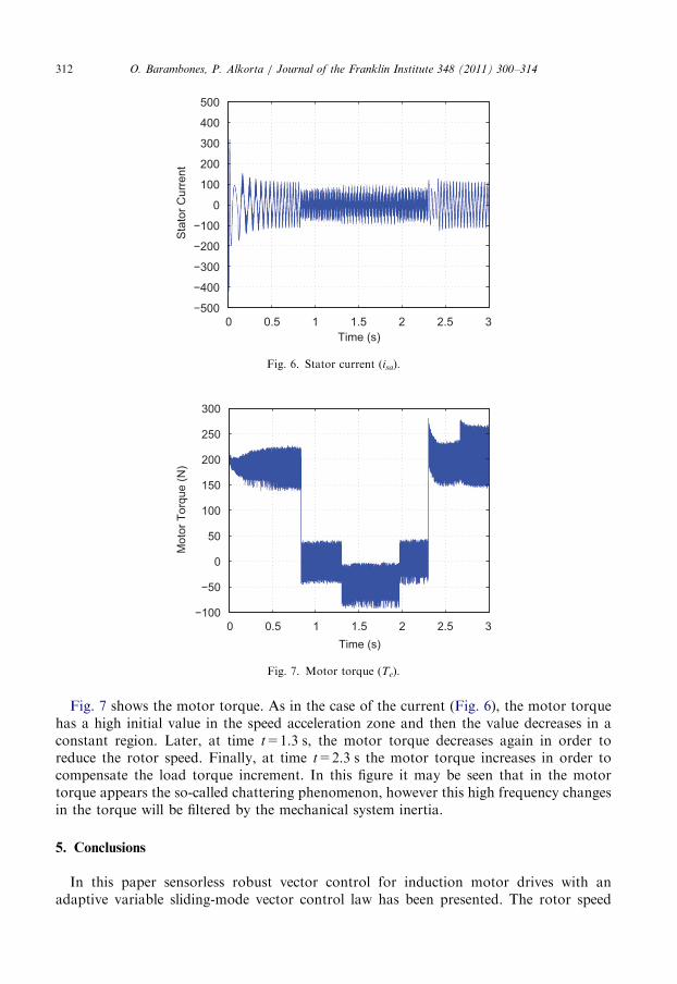
from zero and then it is increased until its value is high enough to compensate for thesystem uncertainties. Besides, the sliding remains constant because the system uncertaintiesremain constant as well. Later, at time 2.3 s, there is an increment in the systemuncertainties caused by the increment in the load torque. Therefore, the sliding should beadapted once again in order to overcome the new system uncertainties. As it can be seen inthe figure after the sliding gain is adapted, it remains constant again, since the systemuncertainties remain constant as well.It should be noted that the adaptive sliding gain allows to employ a smaller sliding gain,
so that the value of the sliding gain do not have to be chosen high enough to compensatefor all possible system uncertainties, because with the proposed adaptive scheme the slidinggain is adapted (if it is necessary) when a new uncertainty appears in the system in order tosurmount this uncertainty.Fig. 5 shows the time evolution of the sliding variable. In this figure it can be seen that
the system reach the sliding condition (S(t)=0) at time t=0.13 s, but then the system loses
0 0.5 1 1.5 2 2.5 30
20
40
60
80
100
120
Time (s)
Rot
or S
peed
(rad
/s)
wm*
wm
Fig. 3. Reference and real rotor speed signals (wmn , wm).
0 0.5 1 1.5 2 2.5 3−0.5
0
0.5
1
1.5
2
2.5
3
3.5
4
Time (s)
Slid
ing
Var
iabl
e
Fig. 5. Sliding variable.
0 0.5 1 1.5 2 2.5 30
2
4
6
8
10
12
14
Time (s)
Slid
ing
Gai
n
Fig. 4. Estimated sliding gain ðb̂Þ.
O. Barambones, P. Alkorta / Journal of the Franklin Institute 348 (2011) 300–314 311
this condition at time t=2.3 s due to the torque increment which, in turn, produces anincrement in the system uncertainties that cannot be compensated by the actual value ofthe sliding gain. However, after a transitory time in which the sliding gain is adapted inorder to compensate the new system uncertainty, the system reaches the slidingcondition again.
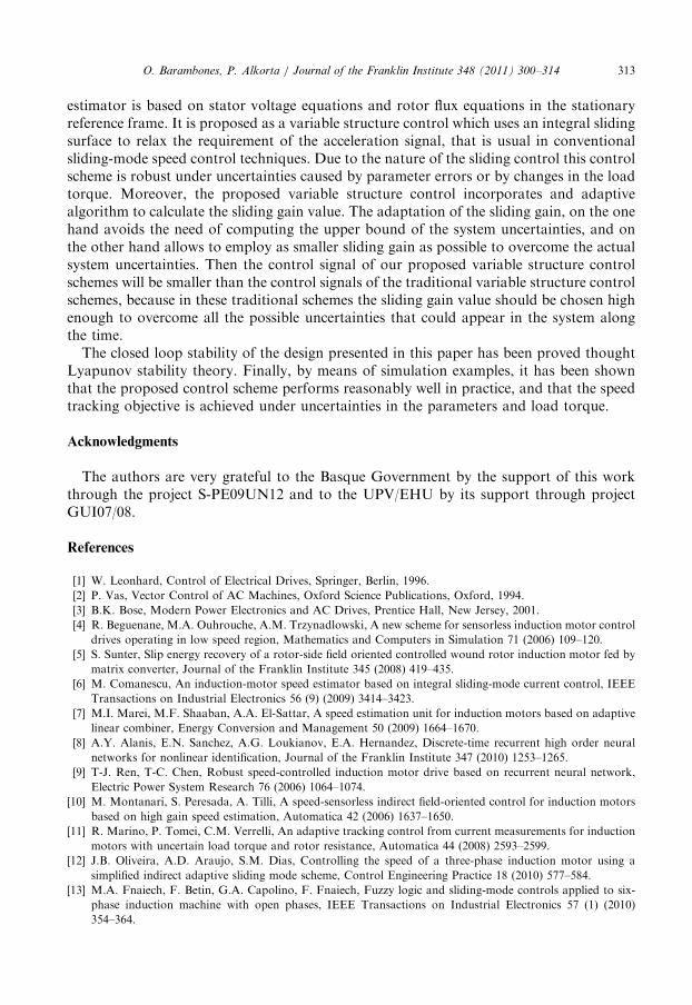
Fig. 6 shows the current of one stator winding. This figure shows that in the initial state,the current signal presents a high value because a high torque is necessary to increment therotor speed due to the rotor inertia. Then, in the constant-speed region, the motor torqueonly has to compensate the friction and therefore, the current is lower. Finally, at timet=2.3 s the current increases because the load torque has been increased.
0 0.5 1 1.5 2 2.5 3−500
−400
−300
−200
−100
0
100
200
300
400
500
Time (s)
Sta
tor C
urre
nt
Fig. 6. Stator current (isa).
0 0.5 1 1.5 2 2.5 3−100
−50
0
50
100
150
200
250
300
Mot
or T
orqu
e (N
)
Time (s)
Fig. 7. Motor torque (Te).
O. Barambones, P. Alkorta / Journal of the Franklin Institute 348 (2011) 300–314312
Fig. 7 shows the motor torque. As in the case of the current (Fig. 6), the motor torquehas a high initial value in the speed acceleration zone and then the value decreases in aconstant region. Later, at time t=1.3 s, the motor torque decreases again in order toreduce the rotor speed. Finally, at time t=2.3 s the motor torque increases in order tocompensate the load torque increment. In this figure it may be seen that in the motortorque appears the so-called chattering phenomenon, however this high frequency changesin the torque will be filtered by the mechanical system inertia.
5. Conclusions
In this paper sensorless robust vector control for induction motor drives with anadaptive variable sliding-mode vector control law has been presented. The rotor speed
O. Barambones, P. Alkorta / Journal of the Franklin Institute 348 (2011) 300–314 313
estimator is based on stator voltage equations and rotor flux equations in the stationaryreference frame. It is proposed as a variable structure control which uses an integral slidingsurface to relax the requirement of the acceleration signal, that is usual in conventionalsliding-mode speed control techniques. Due to the nature of the sliding control this controlscheme is robust under uncertainties caused by parameter errors or by changes in the loadtorque. Moreover, the proposed variable structure control incorporates and adaptivealgorithm to calculate the sliding gain value. The adaptation of the sliding gain, on the onehand avoids the need of computing the upper bound of the system uncertainties, and onthe other hand allows to employ as smaller sliding gain as possible to overcome the actualsystem uncertainties. Then the control signal of our proposed variable structure controlschemes will be smaller than the control signals of the traditional variable structure controlschemes, because in these traditional schemes the sliding gain value should be chosen highenough to overcome all the possible uncertainties that could appear in the system alongthe time.
The closed loop stability of the design presented in this paper has been proved thoughtLyapunov stability theory. Finally, by means of simulation examples, it has been shownthat the proposed control scheme performs reasonably well in practice, and that the speedtracking objective is achieved under uncertainties in the parameters and load torque.
Acknowledgments
The authors are very grateful to the Basque Government by the support of this workthrough the project S-PE09UN12 and to the UPV/EHU by its support through projectGUI07/08.
References
[1] W. Leonhard, Control of Electrical Drives, Springer, Berlin, 1996.
[2] P. Vas, Vector Control of AC Machines, Oxford Science Publications, Oxford, 1994.
[3] B.K. Bose, Modern Power Electronics and AC Drives, Prentice Hall, New Jersey, 2001.
[4] R. Beguenane, M.A. Ouhrouche, A.M. Trzynadlowski, A new scheme for sensorless induction motor control
drives operating in low speed region, Mathematics and Computers in Simulation 71 (2006) 109–120.
[5] S. Sunter, Slip energy recovery of a rotor-side field oriented controlled wound rotor induction motor fed by
matrix converter, Journal of the Franklin Institute 345 (2008) 419–435.
[6] M. Comanescu, An induction-motor speed estimator based on integral sliding-mode current control, IEEE
Transactions on Industrial Electronics 56 (9) (2009) 3414–3423.
[7] M.I. Marei, M.F. Shaaban, A.A. El-Sattar, A speed estimation unit for induction motors based on adaptive
linear combiner, Energy Conversion and Management 50 (2009) 1664–1670.
[8] A.Y. Alanis, E.N. Sanchez, A.G. Loukianov, E.A. Hernandez, Discrete-time recurrent high order neural
networks for nonlinear identification, Journal of the Franklin Institute 347 (2010) 1253–1265.
[9] T-J. Ren, T-C. Chen, Robust speed-controlled induction motor drive based on recurrent neural network,
Electric Power System Research 76 (2006) 1064–1074.
[10] M. Montanari, S. Peresada, A. Tilli, A speed-sensorless indirect field-oriented control for induction motors
based on high gain speed estimation, Automatica 42 (2006) 1637–1650.
[11] R. Marino, P. Tomei, C.M. Verrelli, An adaptive tracking control from current measurements for induction
motors with uncertain load torque and rotor resistance, Automatica 44 (2008) 2593–2599.
[12] J.B. Oliveira, A.D. Araujo, S.M. Dias, Controlling the speed of a three-phase induction motor using a
simplified indirect adaptive sliding mode scheme, Control Engineering Practice 18 (2010) 577–584.
[13] M.A. Fnaiech, F. Betin, G.A. Capolino, F. Fnaiech, Fuzzy logic and sliding-mode controls applied to six-
phase induction machine with open phases, IEEE Transactions on Industrial Electronics 57 (1) (2010)
354–364.
O. Barambones, P. Alkorta / Journal of the Franklin Institute 348 (2011) 300–314314
[14] M. Montazeri-Gh, A. Poursamad, B. Ghalichi, Application of genetic algorithm for optimization of control
strategy in parallel hybrid electric vehicles, Journal of the Franklin Institute 343 (2006) 420–435.
[15] A. Benchaib, C. Edwards, Nonlinear sliding mode control of an induction motor, International Journal of
Adaptive Control and Signal Procesing 14 (2000) 201–221.
[16] O. Barambones, A.J. Garrido, A sensorless variable structure control of induction motor drives, Electric
Power Systems Research 72 (2004) 21–32.
[17] R. Yazdanpanah, J. Soltani, G.R. Arab Markadeh, Nonlinear torque and stator flux controller for induction
motor drive based on adaptive input–output feedback linearization and sliding mode control, Energy
Conversion and Management 49 (2008) 541–550.
[18] B. Castillo-Toledo, S. Di Gennaro, A.G. Loukianov, J. Rivera, Discrete time sliding mode control with
application to induction motors, Automatica 44 (2008) 3036–3045.
[19] T. Or"owska-Kowalska, M. Kami �nski, K. Szabat, Implementation of a sliding-mode controller with an
integral function and fuzzy gain value for the electrical drive with an elastic joint, IEEE Transactions on
Industrial Electronics 57 (4) (2010) 1309–1317.
[20] V.I. Utkin, Sliding mode control design principles and applications to electric drives, IEEE Transactions on
Industrial Electronics 40 (1993) 26–36.
[21] H. Yang, Y. Xia, P. Shi, Observer-based sliding mode control for a class of discrete systems via delta
operator approach, Journal of the Franklin Institute 347 (2010) 1199–1213.
[22] I. Boiko, Frequency domain precision analysis and design of sliding mode observers, Journal of the Franklin
Institute 347 (2010) 899–909.
[23] T. Furuhashi, S. Sangwongwanich, S. Okuma, A position-and-velocity sensorless control for brushless DC
motors using an adaptive sliding mode observer, IEEE Transactions on Industrial Electronics 39 (1992)
89–95.
[24] A.B. Proca, A. Keyhani, J.M. Miller, Sensorless sliding-mode control of induction motors using operating
condition dependent models, IEEE Transactions on Energy Conversion 18 (2003) 205–212.
[25] G. Bartolini, A. Pisano, E. Punta, E. Usai, A survey of applications of second-order sliding mode control to
mechanical systems, International Journal of Control 76 (2003) 875–892.
[26] M. Rashed, K.B. Goh, M.W. Dunnigan, P.F.A. MacConnell, A.F. Stronach, B.W. Williams, Sensorless
second-order sliding-mode speed control of a voltage-fed induction-motor drive using nonlinear state
feedback, IEE Proceedings Electric Power Applications 152 (2005) 1127–1136.
[27] C. Aurora, A. Ferrara, A sliding mode observer for sensorless induction motor speed regulation,
International Journal of Systems Science 38 (2007) 913–929.
[28] Y. Xia, Z. Zhu, C. Li, H. Yang, Q. Zhu, Robust adaptive sliding mode control for uncertain discrete-time
systems with time delay, Journal of the Franklin Institute 347 (1) (2010) 339–357.
[29] M.C. Pai, Design of adaptive sliding mode controller for robust tracking and model following, Journal of the
Franklin Institute 347 (2010) 1838–1849.
[30] J.J.E. Slotine, W. Li, Applied Nonlinear Control, Prentice-Hall, Englewood Cliffs, NJ, USA, 1991.


![Sliding mode control design principles and applications …eusai/BOSIO/[7]-Utkin-TIE-1993.pdf · Sliding Mode Control Design Principles and Applications to Electric Drives ... SLIDING](https://img.pdfslide.us/doc/110x75/5b8e42d909d3f2a8408d4ff4/sliding-mode-control-design-principles-and-applications-eusaibosio7-utkin-tie-1993pdf.jpg)