Embed Size (px)
Citation preview
IOSR Journal of Electrical and Electronics Engineering (IOSR-JEEE)
e-ISSN: 2278-1676,p-ISSN: 2320-3331, Volume 7, Issue 6 (Sep. - Oct. 2013), PP 32-39 www.iosrjournals.org
www.iosrjournals.org 32 | Page
A Proportional-Integral-Derivative Control Scheme of Mobile
Robotic platforms using MATLAB
Kunal Agarwal1, Shadan Mahtab
2 , Sourav Bandyopadhyay
3 ,
Sauvik Das Gupta4
1,2,3Department of AEIE, Heritage Institute of Technology, Kolkata, West Bengal, India 4School of Electrical & Computer Engineering, Oklahoma State University, Stillwater, OK, USA
Abstract: This paper proposes an approach for the navigation of mobile robots namely Khepera 3 and iRobot
Create in a designated environment. In this study, the navigation system of Khepera 3 includes the motion of the
mobile robot at a particular angle to reach a particular goal and avoidance of the obstacle that may occur in its path. Obstacle avoidance is realized using Blending and Hard switching techniques respectively and the
navigation system of iRobot Create includes its movement in a rectangular path. In controlling the navigation
of the robots, Proportional-Integral-Derivative (PID) controller is used. The most suitable set of values of PID
parameters implemented for safe and effective navigation of the robots have been presented. Computer
simulation is done using MATLAB software.
Keywords: Navigation, Mobile robots, Obstacle avoidance, Blending, Hard switching, PID.
I. Introduction A proportional-integral-derivative controller (PID controller) is a generic control loop feedback
mechanism widely used in industrial control systems [1]. PID algorithm consists of three basic coefficients;
Proportional, Integral and Derivative which are varied to get optimal response. The basic idea behind a PID
controller is to read a sensor, then compute the desired actuator output by calculating Proportional, Integral, and Derivative responses and summing those three components to compute the output[2].
II. PID Theory a.Proportional Response
The Proportional term produces an output value that is proportional to the current error value. The
proportional response can be adjusted by multiplying the error by a constant called the proportional gain
constant (KP).
The proportional response is given by: Pout=KP*e(t) (1)
Where, KP=Proportional gain
e=error
t=instantaneous (present) time
b. Integral Response The Integral component sums the error term over time. The result is that even a small error term will
cause the integral component to increase slowly. The integral term in a PID controller is the sum of the
instantaneous error over time and gives the accumulated offset that should have been corrected previously. The
accumulated error is then multiplied by the integral gain (KI) and added to the controller output.
The integral response is given by:
Iout = KI (2)
Where, KI=Integral gain
=Variable of integration, takes on values from time 0 to present time, t.
c. Derivative Response The Derivative response in a PID controller is calculated by determining the slope of the error over
time and multiplying this rate of change by the derivative gain (KD).
The derivative response is given by:
Dout=KD( ) (3)
A Proportional-Integral-Derivative Control Scheme of Mobile Robotic platforms using MATLAB
www.iosrjournals.org 33 | Page
Where, KD=derivative gain
III. PID controller transfer function The controller output, u(t),combining equations (1), (2) and (3) is given by:
u(t)=Kp*e(t) + KI + KD( ) (4)
In continuous s-domain, the corresponding PID controller transfer function, GC(s) is given by [3]:
GC(s) =KP + KI/s + KD*s (5)
Figure 1. General block diagram of PID controller
IV. Application of PID control in mobile robotics Proportional-Integral-Derivative (PID) control is one of the most common control algorithms used in
automation sector and has been universally accepted in industrial control in spite of the development of
advanced control strategies [4]. The popularity of PID controllers can be attributed partly to their robust
performance in a wide range of operating conditions and partly to their functional simplicity, which allows engineers to operate them in a simple, straightforward manner. PID controllers are widely used in the robotic
industry in controlling the operation of mobile robots.
Mobile robotics is a field of great interest and rapid development. With related technologies changing
rapidly, different kinds of mobile robots have been widely used in many indoor and outdoor applications such as
spot welding, loading/unloading of parcels, vacuum cleaning, defence and security [5]. In this paper, we are
dealing with the navigation of mobile robot namely, the Khepera 3and iRobot Create using PID controller.
The Khepera 3 robot integration is a product of the Swiss company-K Team. Features available on the platform
include an upgradable embedded computing power using the KoreBot system, multiple sensor arrays for both
long range and short range object detection, swappable battery pack system for optimal autonomy, and
differential drive odometry[6]. The Khepera 3 robot embeds lots of sensors and advanced computational power
which enhances its application in education and research.
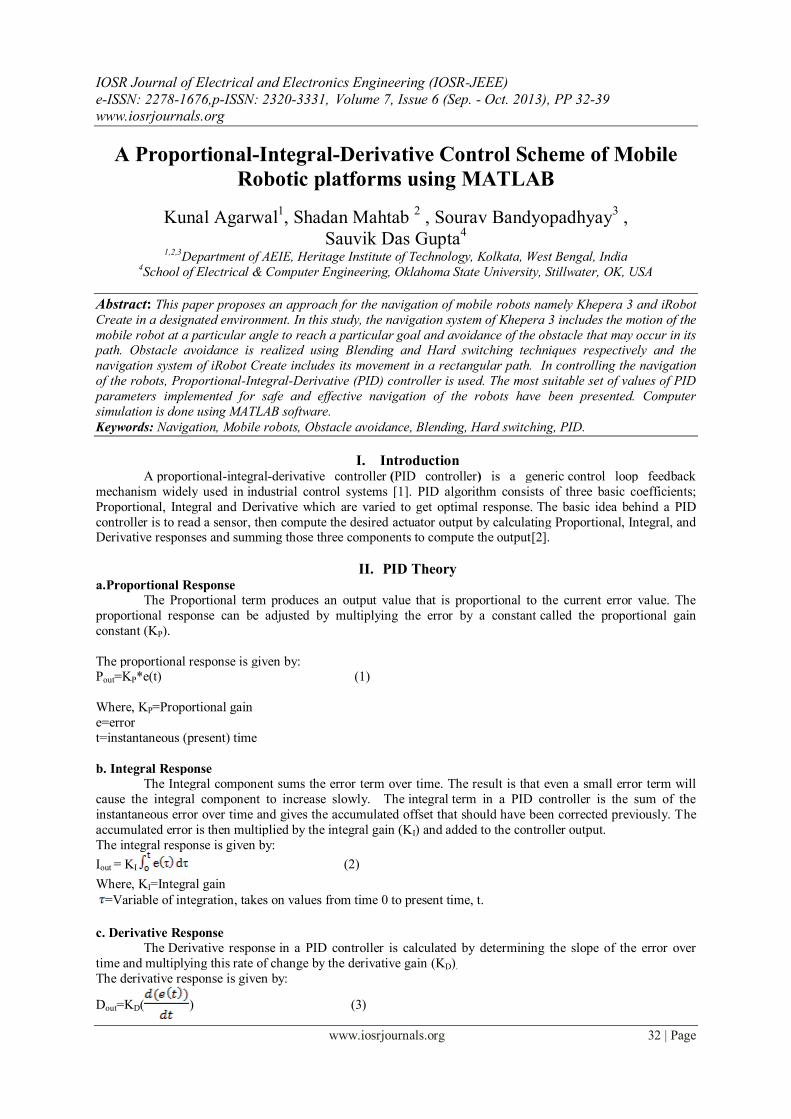
Figure 2: Position of the IR sensors in Khepera 3
Khepera 3 is equipped with 11 infrared (IR) range sensors, of which nine are located in a ring around it and two
are located on the underside of the robot. The IR sensors are complemented by a set of five ultrasonic sensors. It
is powered by a single battery on the underside and can be controlled via software on its embedded Linux
computer.

A Proportional-Integral-Derivative Control Scheme of Mobile Robotic platforms using MATLAB
www.iosrjournals.org 34 | Page
Figure 3: Position of wheel and sensors in iRobot Create
Create is a mobile robot platform developed by the firm-iRobot which is used by students, educators and
developers. It is a preassembled robot. Users can write custom software using a variety of methods that apply
“streaming sensor data” mode of the robot for more control. [7]
The subsequent parts of the paper discuss the various control algorithms designed and tested on these robotic
platforms with their related results. Simulation of the algorithms was done on the Khepera 3 robot and a real-
time implementation was carried out on the iRobot Create robotic platform. Figure 4 clearly depicts the control
flow of the algorithms used.
V. Go To Angle Go To Angle steers the robot towards a angle with a constant velocity using PID controller. This can be
done using MATLAB program with the following steps:
Step 1: Compute the left and right wheel speeds for go to angle.
Step 2: Inputs are given to the robot („theta the desired angle in radians and „v‟the linear velocity in meter/second.)
Step 3: Output variables are defined. („v‟ and „w‟, „v‟ is the linear velocity and „w‟ is angular velocity).
Step 4: Gains are specified. (KP, KI and KD )
Step 5: Go To Angle algorithm is developed.
Step 6: Error tracking is done by continuously calculating the error difference between the desired angle
„theta_d‟ and the angle calculated from the sensor data input „theta‟. The robot will continue this process until
the error becomes zero thus maintaining the angle.
For error tracking we use atan2 command to keep the error in the range [-π, π] [8].
Step 7: Result is achieved.
Figure 5: Go To Angle.
Since there is no distance specified or any obstacle avoidance code developed the robot will continue to move
even after the desired angle is achieved (theta-d - theta = 0). Thus when the robot reaches the red wall it will
crash and stop at that position [8].
Go to angle Go to goal Avoid obstacle
Figure 4: Steps for building the various algorithms based on the PID control.
A Proportional-Integral-Derivative Control Scheme of Mobile Robotic platforms using MATLAB
www.iosrjournals.org 35 | Page
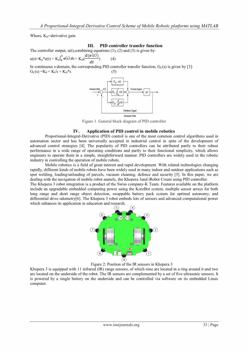
Figure 6: Go To Angle output curve
Figure 6 is a go to angle output curve which shows change in angle with respect to time in the blue line, the red
dotted line shows the desired angle. The curve shows very smooth change in angle.
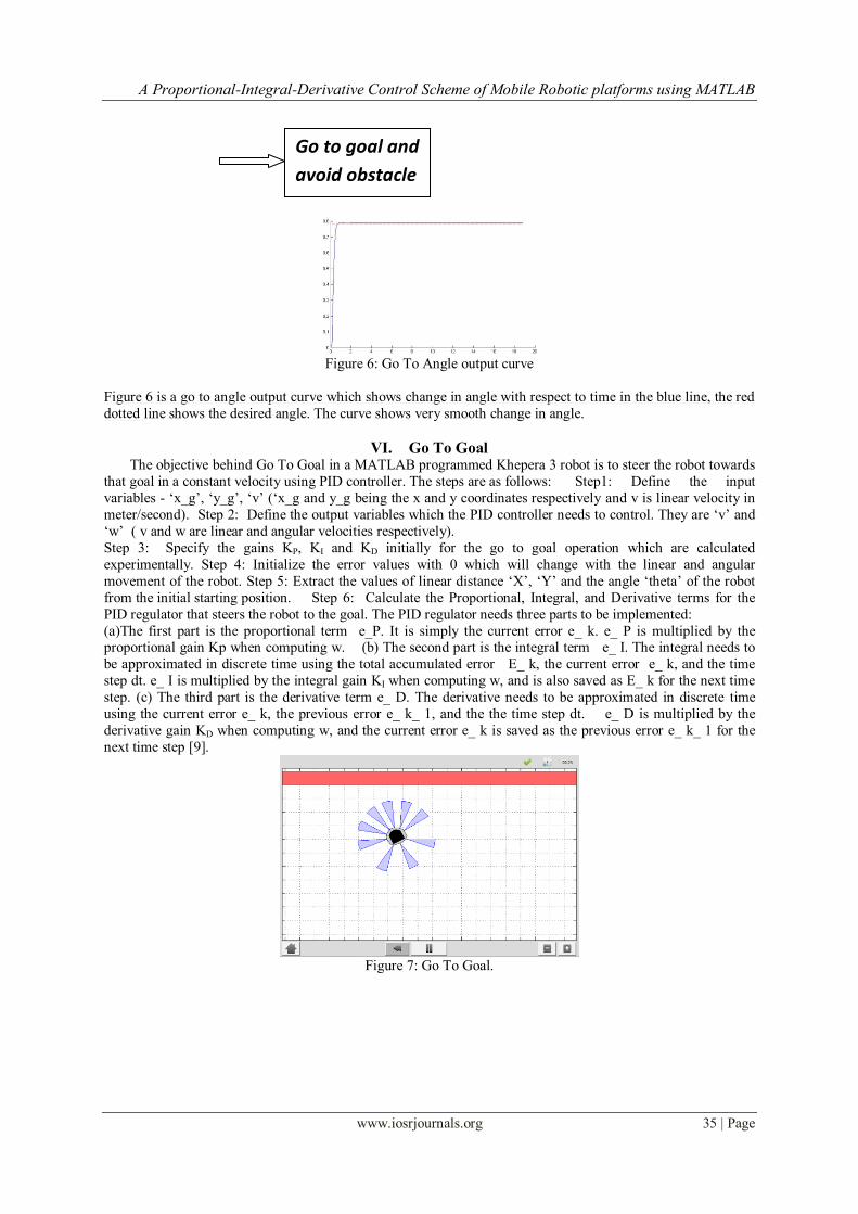
VI. Go To Goal The objective behind Go To Goal in a MATLAB programmed Khepera 3 robot is to steer the robot towards
that goal in a constant velocity using PID controller. The steps are as follows: Step1: Define the input
variables - „x_g‟, „y_g‟, „v‟ („x_g and y_g being the x and y coordinates respectively and v is linear velocity in
meter/second). Step 2: Define the output variables which the PID controller needs to control. They are „v‟ and
„w‟ ( v and w are linear and angular velocities respectively).
Step 3: Specify the gains KP, KI and KD initially for the go to goal operation which are calculated
experimentally. Step 4: Initialize the error values with 0 which will change with the linear and angular
movement of the robot. Step 5: Extract the values of linear distance „X‟, „Y‟ and the angle „theta‟ of the robot
from the initial starting position. Step 6: Calculate the Proportional, Integral, and Derivative terms for the
PID regulator that steers the robot to the goal. The PID regulator needs three parts to be implemented:
(a)The first part is the proportional term e_P. It is simply the current error e_ k. e_ P is multiplied by the proportional gain Kp when computing w. (b) The second part is the integral term e_ I. The integral needs to
be approximated in discrete time using the total accumulated error E_ k, the current error e_ k, and the time
step dt. e_ I is multiplied by the integral gain KI when computing w, and is also saved as E_ k for the next time
step. (c) The third part is the derivative term e_ D. The derivative needs to be approximated in discrete time
using the current error e_ k, the previous error e_ k_ 1, and the the time step dt. e_ D is multiplied by the
derivative gain KD when computing w, and the current error e_ k is saved as the previous error e_ k_ 1 for the
next time step [9].
Figure 7: Go To Goal.
Go to goal and
avoid obstacle
A Proportional-Integral-Derivative Control Scheme of Mobile Robotic platforms using MATLAB
www.iosrjournals.org 36 | Page
Figure 8: Go to Goal output curve
The output curve shows change in angle with respect to time in the blue line, the red dotted line shows the desired angle. The curve shows very smooth change in angle and also the goal is reached in a very short span of
time.
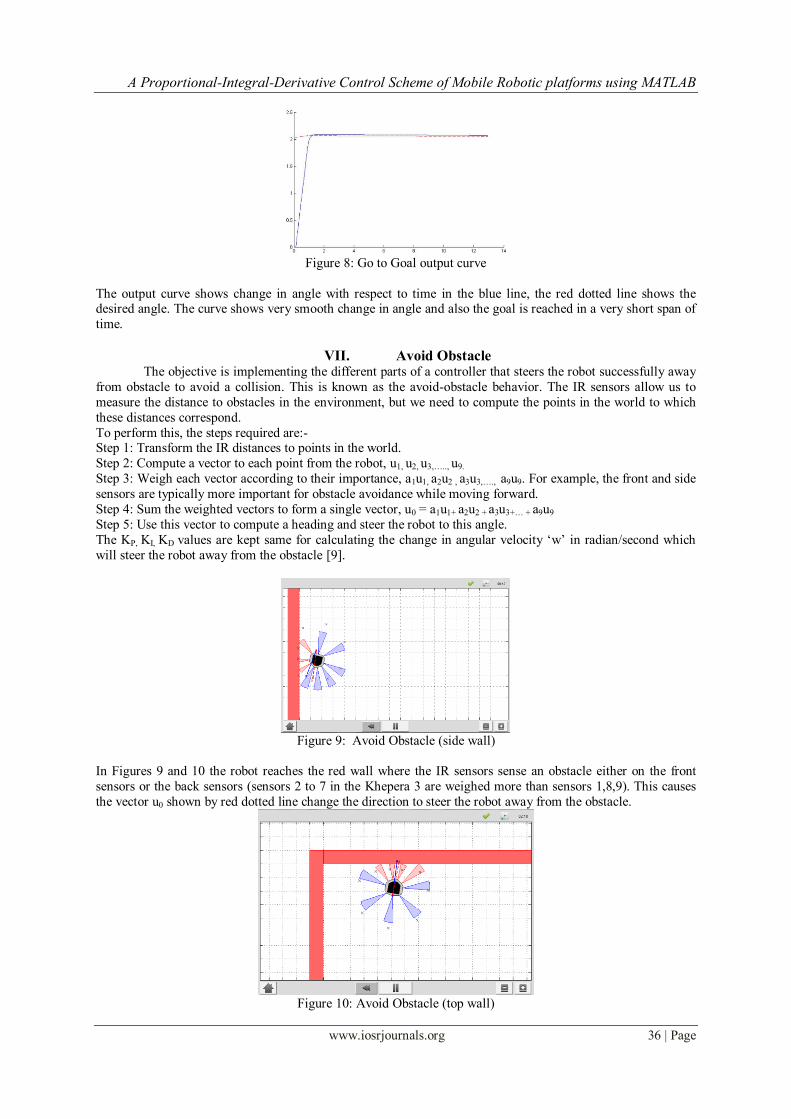
VII. Avoid Obstacle The objective is implementing the different parts of a controller that steers the robot successfully away
from obstacle to avoid a collision. This is known as the avoid-obstacle behavior. The IR sensors allow us to
measure the distance to obstacles in the environment, but we need to compute the points in the world to which
these distances correspond.
To perform this, the steps required are:- Step 1: Transform the IR distances to points in the world.
Step 2: Compute a vector to each point from the robot, u1, u2, u3,….., u9.
Step 3: Weigh each vector according to their importance, a1u1, a2u2 , a3u3,…., a9u9. For example, the front and side
sensors are typically more important for obstacle avoidance while moving forward.
Step 4: Sum the weighted vectors to form a single vector, u0 = a1u1+ a2u2 + a3u3+… + a9u9
Step 5: Use this vector to compute a heading and steer the robot to this angle.
The KP, KI, KD values are kept same for calculating the change in angular velocity „w‟ in radian/second which
will steer the robot away from the obstacle [9].
Figure 9: Avoid Obstacle (side wall)
In Figures 9 and 10 the robot reaches the red wall where the IR sensors sense an obstacle either on the front
sensors or the back sensors (sensors 2 to 7 in the Khepera 3 are weighed more than sensors 1,8,9). This causes
the vector u0 shown by red dotted line change the direction to steer the robot away from the obstacle.
Figure 10: Avoid Obstacle (top wall)
A Proportional-Integral-Derivative Control Scheme of Mobile Robotic platforms using MATLAB
www.iosrjournals.org 37 | Page
VIII. Go To Goal and Avoid Obstacle a. Blending
Blending provides us to make a small improvement to the go-to-goal and avoid-obstacle controllers.
Arbitration between the two controllers allows the robot to drive to a goal, while not colliding with any obstacle
on the way. We will improve the performance of both the Go-to-Goal and Avoid-Obstacle behavior by
dynamically adjusting the linear velocity based on the angular velocity of the robot. The actuator limits of the
robot limit the linear velocity to a range of [-0.3; 0.3] m/s and the angular velocity to a range of [-2.765;
2.765] rad/s. It is important to remember that with a differential drive, we cannot, drive the robot at the
maximum linear and angular velocities. There is a trade-off between linear and angular velocities: linear
velocity has to decrease for angular velocity to increase, and vice versa. So, we have designed the system
accordingly. Now we start the blending process. The solutions to the Go-to-Goal and Avoid-Obstacle controllers
have been combined into a single controller, one vector pointing to the goal from the robot, and another vector pointing from the robot to a point in space away from obstacle. These two vectors are combined (blended) into
a component vector, which is a vector that points the robot both away from obstacle and towards the goal [9].
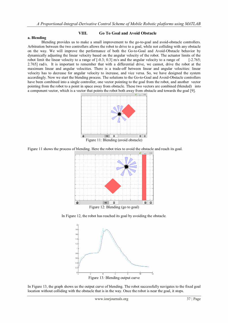
Figure 11: Blending (avoid obstacle)
Figure 11 shows the process of blending. Here the robot tries to avoid the obstacle and reach its goal.
Figure 12: Blending (go to goal)
In Figure 12, the robot has reached its goal by avoiding the obstacle.
Figure 13: Blending output curve
In Figure 13, the graph shows us the output curve of blending. The robot successfully navigates to the fixed goal
location without colliding with the obstacle that is in the way. Once the robot is near the goal, it stops.

A Proportional-Integral-Derivative Control Scheme of Mobile Robotic platforms using MATLAB
www.iosrjournals.org 38 | Page
The blending controller's advantage is that it smoothly blends Go-to-Goal and Avoid - Obstacle together.
However, when there are no obstacle around, it is better to purely use go-to-goal, and when the robot gets
dangerously close, it is better to only use avoid-obstacle. The switching logic performs better in those kinds of situations.
b. Hard switching
In Hard switching logic the robot continuously switches between its two objectives i.e., Go to Goal and
Avoid - Obstacle, while it tries to avoid an obstacle before reaching the goal.
Figure 14: Hard switching output curve
The Hard switching technique has greater efficiency in performing the objective (avoid obstacle and go to goal)
at higher linear velocities. But as the output curve has depicted, the switching technique causes heavy vibrations
in the robot, which can cause damage to the internal hardware of the Khepera 3 or other robots. This makes
blending technique more acceptable as it uses a priority based technique. When the priority is more to avoid
obstacle the robot will perform only avoid obstacle objective, otherwise it will perform go to goal. This process causes much smoother transition between the Go to Goal and Avoid - Obstacle.
IX. Go In a Rectangle using iRobot Create For practically testing the objectives in real-time, the Go To Goal objective is done on iRobot Create.
The objective is to steer the robot such that it moves in a rectangular path. The robot must stop after traveling
the entire perimeter. Step 1: To travel length forward, create the distance entered in meters. Positive distances
move the Create forward, negative distances move the Create backwards. Speed should be between 0.025 and
0.5 m/s. Step 2: To turn angle specify an angle to turn though (in degrees). Positive is counter clockwise and
negative is clockwise and a speed (in rad/sec). Robot turns in place and stops when done. Speed is in rad/sec (between 0 and 0.2).For the first turn 90 degree angle is given. Step 3: To travel the breadth forward create
forward distance in meter. Speed should be between 0.025 and 0.5 m/s. Step 4: Turn angle by +90 degree. Step
5: Travel length forward. Step 6: Turn angle by +90 degree. Step 7: Travel breadth forward.
Following this procedure the iRobot Create can travel a rectangular path using PID control.
X. Discussions and Conclusion A PID controlled navigation system for mobile robots, Khepera 3 and iRobot Create is implemented
using MATLAB. The proposed algorithm optimised parameters of PID controller which is applied to the
simulation and practical experimentation schemes. In case of the navigation system of Khepera 3, for Go To Angle task, only Proportional control is used.
For Go to Goal task, small Integral and Derivative control is applied along with Proportional control. In the
comprehensive navigation system combining the tasks of Go To Angle, Go To Goal and Avoid Obstacle, there
is a compromise weight to be assigned to Go To Goal and Avoid Obstacle tasks respectively depending upon
the environment in which the robot is navigating. Blending and Hard-switching are the methods used for
combination of the tasks. While Blending ensures smoother navigation minimising vibrations in the robot, Hard-
switching is a more efficient technique when the linear velocity of the robot is high.
In case of the navigation system of iRobot Create, the robot traverses a rectangular path in counter clockwise
direction using adequate Proportional, Integral and Derivative control.
The final results show that the proposed control system for both the robots respectively, successfully provides a
simple and effective method of mobile robot navigation. Future work will include developing algorithm for Avoid Obstacle and combination of Go to Angle, Go To
Goal and Avoid Obstacle on iRobot Create platform. Also tracking of reference trajectory by optimising PID
parameters using genetic algorithm can be implemented on Khepera 3 platform in future.

A Proportional-Integral-Derivative Control Scheme of Mobile Robotic platforms using MATLAB
www.iosrjournals.org 39 | Page
Acknowledgement The authors are grateful to ESL (www.eschoollearning.net), Kolkata for providing hardware and
software support in carrying out this work. The authors would also like to extend their gratitude towards the
organization for the detailed intellectual support provided to them during the project.
References [1]. ”PID Controller” [Online]. Available: http://en.wikipedia.org/wiki/PID_controller.
[2]. ”PID theory” [Online]. Available: http://www.ni.com/white-paper/3782/en/
[3]. RAJKUMAR BANSAL, A.PATRA, VIJAYBHURIA, “Design of PID Controller for Plant Control and Comparison with Z-N PID
Controller”, International Journal of Emerging Technology and Advanced Engineering ,Volume 2, Issue 4, April 2012.
[4]. S. N. DEEPA, G. SUGUMARAN, “Design of PID Controller for Higher Order Continuous Systems using MPSO based Model
Formulation Technique”, International Journal of Electrical and Electronics Engineering, 5:4 2011.
[5]. CHIA-JU WU, TING-LI CHIEN, TSONG-LI LEE, and LI-CHUN LAI, “Navigation of a mobile robot in indoor environment”,
Journal of the Chinese Institute of Engineers, Vol. 28, No. 6, pp. 915-924 (2005).
[6]. ”Khepera 3” [Online]. Available: http://www.k-team.com/mobile-robotics-products/khepera-iii.
[7]. ”iRobot Create” [Online]. Available: http://www.irobot.com/us/learn/Educators/Create.aspx.
[8]. ”Simiam”[Online]. Available: http://jdelacroix.github.io/simiam/.
[9]. Sim.I.am: A Robot Simulator by Jean-Pierre de la Croix.
![A Proportional-Integral-Derivative Control Scheme of ... · mechanism widely used in industrial control systems [1]. PID algorithm consists of three basic coefficients; Proportional,](https://img.pdfslide.us/doc/110x75/5edda510ad6a402d6668cadf/a-proportional-integral-derivative-control-scheme-of-mechanism-widely-used-in.jpg)