Embed Size (px)
Citation preview
IMPLEMENTATION OF PROPORTIONAL INTEGRAL DERIVATIVE (PID)
CONTROLLER ON COUPLED TANK LIQUID LEVEL SYSTEM
SAIFUL NORAZWAN BIN MOHD ARIFFIN
UNIVERSITI MALAYSIA PAHANG
“I hereby acknowledge that the scope and quality of this thesis is qualified for the award
of the Bachelor Degree of Electrical Engineering (Power System)”
Signature : ______________________________
Name : MOHD SYAKIRIN BIN RAMLI
Date : 12 NOVEMBER 2008
i
IMPLEMENTATION OF PROPORTIONAL INTEGRAL DERIVATIVE (PID)
CONTROLLER ON COUPLED TANK LIQUID LEVEL SYSTEM
SAIFUL NORAZWAN BIN MOHD ARIFFIN
This thesis is submitted as partial fulfillment of the requirements for the award of the
Bachelor of Electrical Engineering (Power System)
Faculty of Electrical & Electronics Engineering
Universiti Malaysia Pahang
NOVEMBER, 2008
ii
“All the trademark and copyrights use herein are property of their respective owner.
References of information from other sources are quoted accordingly; otherwise the
information presented in this report is solely work of the author.”
Signature : ____________________________
Author : SAIFUL NORAZWAN BIN MOHD ARIFFIN
Date : 11 NOVEMBER 2008

iii
Dedicated to my beloved parents, sibling and friends For giving a constant source of support and encouragement
iv
ACKNOWLEDGEMENT
Assalamualaikum w.b.t
I am grateful to Allah SWT, the most powerful and the most merciful for His
blessing of giving me this opportunity to complete this project successfully. Never
forget, Peace and Prayers to the Prophet, Muhammad s.a.w.
My sincere appreciation to project’s supervisor, En. Mohd Syakirin Bin
Ramli for all the guidance, patience and support through out the project completion. I
am sorry for the entire mistake and all the problems that his have to face during his
supervision.
I would like to thank to laboratory assistance En Mohd Salmizan Bin Mohd
Zain for all the cooperation and help during the project completion at FKEE
laboratories.
I would like to thank my family and my friends for their eternal support .Last,
but not least, I would like to acknowledge the lot of support to Faculty of Electrical
and Electronic Engineering, Universiti Malaysia Pahang in this research. Without
their support the ideas could not have been realized.
Thanks to all. Wassalam.
v
ABSTRACT
Nowadays, the liquid level control is one most important element in industrial
field especially in chemical industry. The basic concept of how the coupled tanks
system work in this project is by using computer as the main control where user can
control the level of liquid in one tank or both tanks. The purpose of this project is to
implement PID controller on coupled tank liquid level system by using visual basic
software. The visual basic software are used because it easy to interface with
hardware. PID controller was used due to widely acceptance applicability in process
industry. The mathematical model of PID controller was used implement as such to
produces suitable output so that the liquid level can be controlled at desired set point.
Meanwhile, the mathematical model of coupled tank liquid level system was derived
to obtain the transfer function of the plant and later be used to simulate the plant
performance in MATLAB program.
vi
ABSTRAK
Pada masa sekarang, kawalan aras cecair adalah satu unsur penting dalam
industri terutama industry kimia. Konsep asas bagaimana untuk tangki berkembar
berfungsi dalam projek ini ialah, dengan menggunakan komputer sebagai pengawal
utama, pengguna boleh mengawal ketinggian cecair di dalam satu tangki atau untuk
kedua-dua tangki. Tesis ini menerangkan tentang cara yang digunakan untuk
mengawal aras air pada ketinggian yang dikehendaki. Tujuan projek ini adalah untuk
melaksanakan pengawal PID pada tanki cecair ketingian berkembar menggunakan
perisian visual basic (VB-6). Perisian visual basic (VB-6) digunakan kerana ia
mudah untuk kemunikasi dengan tanki cecair ketingian berkembar. Pengawal PID
digunakan kerana ia telah digunakan secara meluas dalam industry proses. Formula
matamatik dalam pengawal PID telah digunakan untuk menghasilkan keluaran yang
bersesuain dengan system dikehndaki. Formula matamatik untuk tanki cecair
ketingian berkembar dalam buku manual digunakan sebagai perkara rumus bagi
system tanki cecair ketingian berkembar
vii
TABLE OF CONTENTS
CHAPTER TITLE PAGE
TITLE PAGE i
DECLARATION ii
DEDICATION iii
ACKNOWLEDGEMENT iv
ABSTRACT v
ABSTRAK vi
TABLE OF CONTENTS vii
LIST OF TABLES x
LIST OF FIGURES xi
LIST OF SYMBOL xiv
1 INTRODUCTION
1.1 Overview 1
1.2 Objectives 2
1.3 Scope of the Project 2
1.3.1 Hardware 3
1.3.2 Software 3
1.4 Problem statement 3
1.5 Thesis organization 4
2 LITERATURE REVIEW
2.1 Overview 5
2.2 Couple tank liquid level system 5
2.3 PID controller 6
2.4 Direct Digital Control (DDC) 7
viii
2.5 Summary 7
3 METHODOLOGY
3.1 Overview 8
3.2 Project Structure 9
3.3 Coupled Tank liquid system 11
3.4 Software 12
3.4.1 MATLAB software 12
3.4.2 Visual Basic (VB-6) software 13
3.5 System implementation 14
3.6 Data Acquisition Card (DAQ) 16
3.7 2nd order single output single input (SISO) 18
Plant system
3.8 Summary 21
4 PID CONTROLLER
4.1 Overview 22
4.2 PID controller 22
4.3 Characteristic of PID controller 23
4.4 PID tuning method 24
4.5 Designing the PID controller 25
4.6 Summary 29
5 RESULT AND ANALYSIS
5.1 Parameter 30
5.2 Simulation result 31
5.2.1 MATLAB simulink 31
5.2.2 Simulation data 32
5.2.3 Graph 35
ix
5.3 Real-Time result 35
5.3.1 Visual Basic form 35
5.3.2 Real time data 37
5.3.3 Graph 39
5.4 Comparisons between real-time 40
and simulation result
5.5 Summary 41
6 CONCLUSIONS AND RECOMMENDATION
6.1 Summary of the project 42
6.2 Recommendations for the future work 43
6.3 Costing and commercialization 43
REFERENCES 44
Appendices
A Visual basic program 45-52
x
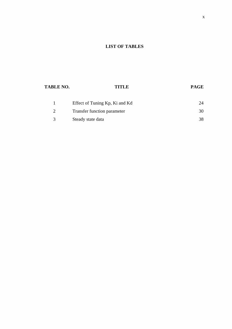
LIST OF TABLES
TABLE NO. TITLE PAGE
1 Effect of Tuning Kp, Ki and Kd 24
2 Transfer function parameter 30
3 Steady state data 38
xi
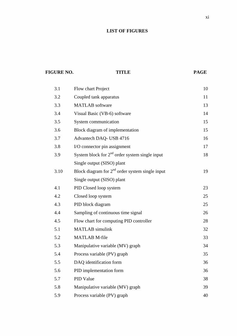
LIST OF FIGURES
FIGURE NO. TITLE PAGE
3.1 Flow chart Project 10
3.2 Coupled tank apparatus 11
3.3 MATLAB software 13
3.4 Visual Basic (VB-6) software 14
3.5 System communication 15
3.6 Block diagram of implementation 15
3.7 Advantech DAQ- USB 4716 16
3.8 I/O connector pin assignment 17
3.9 System block for 2nd order system single input 18
Single output (SISO) plant
3.10 Block diagram for 2nd order system single input 19
Single output (SISO) plant
4.1 PID Closed loop system 23
4.2 Closed loop system 25
4.3 PID block diagram 25
4.4 Sampling of continuous time signal 26
4.5 Flow chart for computing PID controller 28
5.1 MATLAB simulink 32
5.2 MATLAB M-file 33
5.3 Manipulative variable (MV) graph 34
5.4 Process variable (PV) graph 35
5.5 DAQ identification form 36
5.6 PID implementation form 36
5.7 PID Value 38
5.8 Manipulative variable (MV) graph 39
5.9 Process variable (PV) graph 40
xii
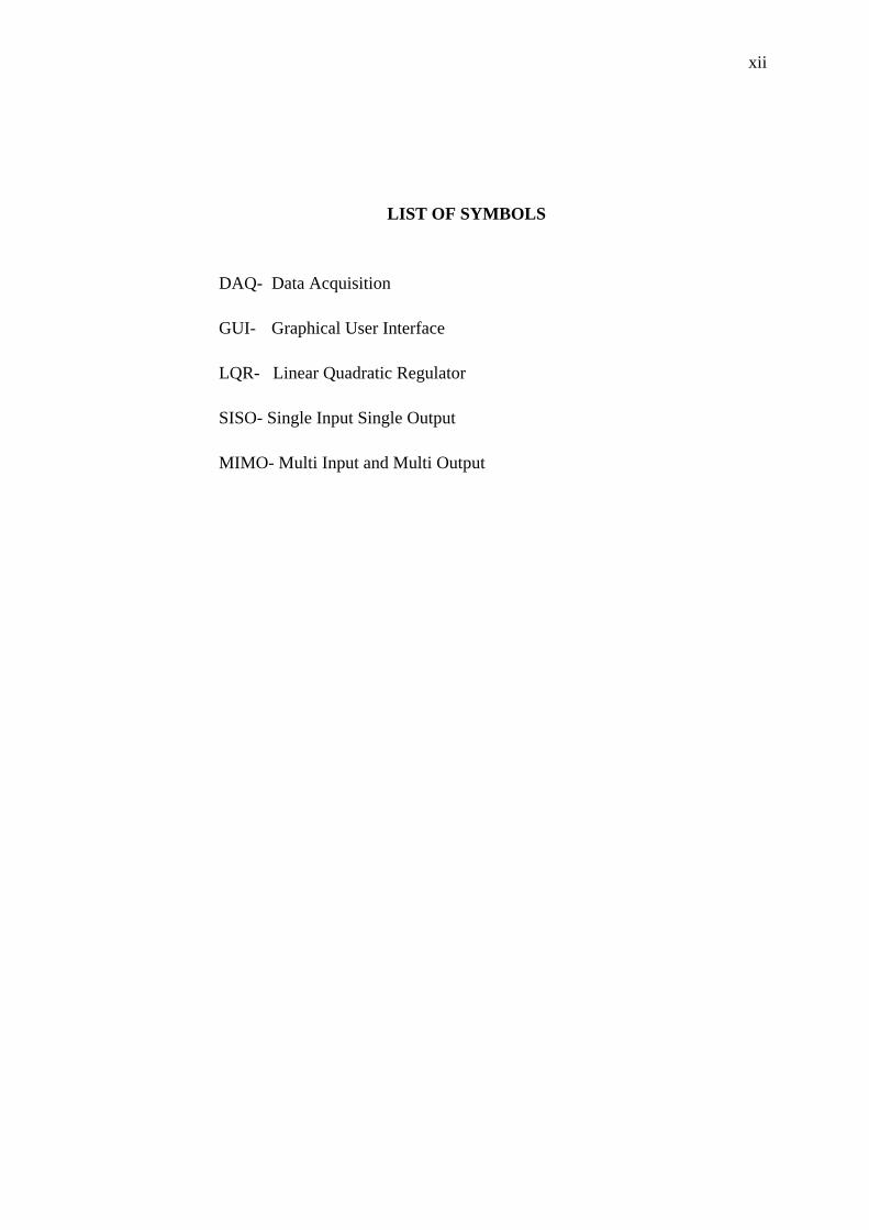
LIST OF SYMBOLS
DAQ- Data Acquisition
GUI- Graphical User Interface
LQR- Linear Quadratic Regulator
SISO- Single Input Single Output
MIMO- Multi Input and Multi Output
1
CHAPTER ONE
INTRODUCTION 1.1. Overview
In the process of industrial there are various parameters need to be controlled
such as temperature, level, and etc. Some process needs to keep the liquid level in the
horizontal tank such as oil, chemical liquid in its. The level control is a type of
control method for common in process system. The level control system must be
controlled by the proper controller. The objective of the controller in the level control
is to maintain a level set point at a given value and be able to accept new set point
values dynamically.
PID controller is widely used in industrial application such as in temperature,
motion and level control. By using PID controller the output will obtain in a short
time, minimal steady state error and can control the overshoot. The proportional
component (Kp) provides an overall control action proportional to the error through
the all pass gain factor. The integral component (Ki) was used to minimize steady
state error through low frequency compensation. The derivative component used to
reduce overshoot and improve transient response through high frequency
compensation.
Water level control is a process of controlling the water level to desired set
point by controlling the pump that used to inject the water to the tank and measured
it by sensor. The important parts of control water level are to the situation that
requires fluid to be supplied to a chemical reactor at a constant rate and to maintain
2
the water at desired level. People generally switch on the pump when their taps go
dry and switch off the pump when the overhead tank starts overflowing. This results
in the unnecessary wastage and sometimes non-availability of water in the case of
emergency. There are some other problem that might occur when level of water is
not control such as when water need to be at constant rate and it used for cooling
system, the system will breakdown because of high temperature.
1.2. Objective
In this project there are several objective should be archived, they are:
1. To implement PID controller for controlling coupled tank liquid level sensor
2. To simulate PID controller for controlling water level sensor in
coupled tank system.
3. To see the effect of tuning proportional (Kp), Integral (Ki) and
derivative (Kd) on the system response.
1.3. Scope Of Project
To make this easier to handle this project was divided, into two difference
part, for hardware and software.
1.3.1 Hardware
The hardware that we used was named by coupled tank liquid level system. It
consists of two small tower-type tanks mounted above a reservoir which functions as
storage for the water. Water is pumped into the top of each tank by two independent
pumps. The head of water in each tank is clearly visible on the attached scale at the
front of the tanks. Each tank is fitted with an outlet, at the side near the base. Data
3
acquisition needs to be used to communicate between hardware and software. There
are several data acquisition cards for input output that can be used such as from
National Instrument, Advantech and others.
1.3.2 Software
The software parts are most difficult, because of needed to study MATLAB
and Visual Basic (Vb-6) software to implement PID controller to the system.
I. MATLAB are used as a simulation for PID controller and coupled tank liquid
level system.
II. To create GUI using Visual Basic 6. Need to understand algorithm for PID
controller for implement to the coupled tank system.
1.5 Problem statement
As real-time control involves algorithms to control a certain processes, and
used complex algorithm. In order to study its performance in terms of
implementation in real-time and simulation at each control features, control of level
of a coupled tank is chosen. This application is widely used in the process industry
especially in chemical industries. In this project, controlling liquid level process will
be done in real-time by applying Proportional-Integral-Derivative (PID) algorithm
and compare with simulation.
Other issues in real-time such as rapid testing, nonlinearity and computational
problem have led researchers in recent years to do intensive work on development
methodologies to enhance control in real-time. Therefore software’s such as Visual
Basic (VB), MATLAB, and other simulation software would reduce the effort for
implementation especially in algorithm to imply.
4
The main interest in this research is to implement a real-time predictive
control algorithm to a coupled tank for level control process using PID controller and
its control performance will be benchmarked against MATLAB simulation using
same controller.
1.6 Thesis Organization
This thesis consists of six chapters including this chapter. The content of each
chapter are outline as follow:
Chapter 1: is about introduction to the thesis. This chapter introducing the
overview of project including objective and the scope of the project.
Chapter 2: is an article review. This chapter provides review about
background of Coupled Tank liquid system, PID controller, PID application and
about how Direct digital control (DDC) is implement.
Chapter 3: Include the project methodology. This will explain about how the
project was organized and the flow of the process in completing this project.
Chapter 4: is about PID controller. This chapter review about how to
implement PID controller for the project.
Chapter 5: is about the result of the MATLAB simulation and real time result
in visual basic will discuss. The output response for each result will analyzed. All the
case studies will analysis in this chapter. Lastly, Chapter 6: is about result based on
this project and the suggestion to improve the system in future.
5
CHAPTER TWO
LITERATURE REVIEW
2.1 Overview
This chapter will review previous research which concern to PID controller,
liquid level control of coupled-tank system and how digital direct control DDC work.
The history about PID controller and their application as well as the usage of couple
tank Liquid level system will be discussed.
2.2 Couple tank Liquid level system
Coupled-Tank Control Apparatus is a low-cost pilot plant designed for
laboratory teaching of both introductory and advanced control systems theory. This
apparatus can be used for teaching system modeling using static and transient
measurements; steady state error analysis; transient response studies; and for
evaluating the design, operation and application of common controllers as well as
controller tuning methods. [1]
6
2.3 PID controller
PID controllers are used in more than 95% of closed-loop industrial
processes. It can be tuned by operators without extensive background in Controls,
unlike many other modern controllers that are much more complex but often provide
only marginal improvement. In fact, most PID controllers are tuned on-site.
Although we are learning all the theories to design the controller, the lengthy
calculations for an initial guess of PID parameters can often be circumvented if we
know a few useful tuning rules.[2] This is especially useful when the system is
unknown.
PID controllers are dominant and popular and, have been widely used since
the 1940’s because one can obtain the desired system responses and it can control a
wide class of systems. A PID controller attempts to correct the error between a
measured process variable and a desired set point [3].
PID controllers have a simple control structure, inexpensive cost, many
proposed systematic tuning methods, and have been used for more than half a
century [4]. PID controller consist of three separated element that are Proportional(P)
which as the proportional value (Kp), Integral (I) consist of proportional error and
the duration of error (Ki) and Derivative (D) determine the rate of change of the
process error (Kd).
There are several method for tuning PID such as Ziegler-Nicholas, Bode's
integrals, disturbance rejection magnitude optimum, pole placement and optimization
methods. However in this project the Ziegler-Nicholas tuning method was use.
The first tuning method was developed in 1942 by Ziegler and Nichols and is
known as Quarter-Amplitude-Damping (QAD) [5]. For this tuning method, first we
must set proportional value (Kp=0), integrated value (Ki=0) and derivative value
(Kd=0) then increase proportional value (Kp) until the output starts overshooting and
ringing significantly. After that Increase KD until the overshoot is reduced to an
acceptable level then lastly Increase KI until the final error is equal to zero.
7
2.4 Direct digital control (DDC)
DDC control consists of computer-based controllers with the control logic
performed by software. Analog-to-Digital (A/D) converters transform analog values
into digital signals that a microprocessor can use [6].
DDC used to collect the data and process the data. The DDC system will
monitor the system by selected time and analyze [7]. The benefits of using DDC are
increase control efficiency, energy efficiency, operation efficiency and DDC systems
are capable of collecting and processing large streams of data [6,7].
Direct Digital Control, known as "DDC", logs electronic temperature
measurements and compares them to the desired settings (set-points), then calculates
an appropriate response if the two aren't equal, and finally sends out new signals to
correct for any difference. Start/stop control and alarm reporting are also
incorporated into DDC. [8].
2.5 Summary
In this chapter, the reason for choosing PID controller and the basic operation
of DDC is mention. Basically the PID controller was choosing because it’s simple
and normally used in control system. Besides that the couple tank liquid level for
case study also was discuss in details. The most important is how to tune the PID
controller. So based on several tuning method the Zeigler-Nicholas will be used as
tuning method.
8
CHAPTER THREE
METHODOLOGY
3.1 Overview
The scope of this chapter is to provide further details on methodology and
approach upon completing this project. Level control is one of the control system
variables which are very important in the industries. A simplified version mock-up of
one of the system like the interacting tanks in such industries is essential in order to
understand its dynamic behavior (Bennett, 1994). Therefore, AISB Coupled-Tank
Control Apparatus CT-001 which is available in UMP’s lab serves as a low-cost pilot
plant that represents the interacting tanks in the actual industries. The CTS-001 will
be used as test bed for real-time implementation of PID controller implementation
Thus system identification of non parametric model is involved in modeling the
system in Visual Basic (VB-6). The model obtained is specialized to both tanks
system (second order single input single output). The process plant, data acquisition
card and the Visual Basic (VB-6) and MATLAB software will be discussed for its
implementation throughout the project in this chapter.
9
3.2 Project Structure
There are few steps taken to initiate this project. These steps are implemented
to assure that the project can be running smoothly and the objective can be achieved.
The basic of the methodology consist of three main tasks. They are:
1. Design phase
2. Development phase
3. verification phase
10
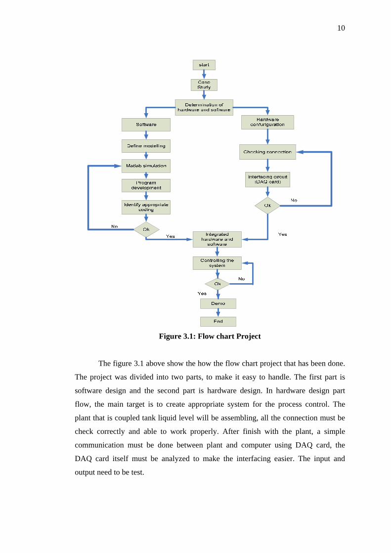
Figure 3.1: Flow chart Project
The figure 3.1 above show the how the flow chart project that has been done.
The project was divided into two parts, to make it easy to handle. The first part is
software design and the second part is hardware design. In hardware design part
flow, the main target is to create appropriate system for the process control. The
plant that is coupled tank liquid level will be assembling, all the connection must be
check correctly and able to work properly. After finish with the plant, a simple
communication must be done between plant and computer using DAQ card, the
DAQ card itself must be analyzed to make the interfacing easier. The input and
output need to be test.


![A Proportional-Integral-Derivative Control Scheme of ... · mechanism widely used in industrial control systems [1]. PID algorithm consists of three basic coefficients; Proportional,](https://img.pdfslide.us/doc/110x75/5edda510ad6a402d6668cadf/a-proportional-integral-derivative-control-scheme-of-mechanism-widely-used-in.jpg)